CANTOPS CTS-RFID-LF03 RFID Reader User Manual
CanTops RFID Reader Users Manual
UserManual.wiki
>
CANTOPS
>
CTS RFID LF03 User Manual
Users Manual
Navigation menu
Upload a User Manual
Namespaces
Wiki Guide
HTML
PDF
Info
Views
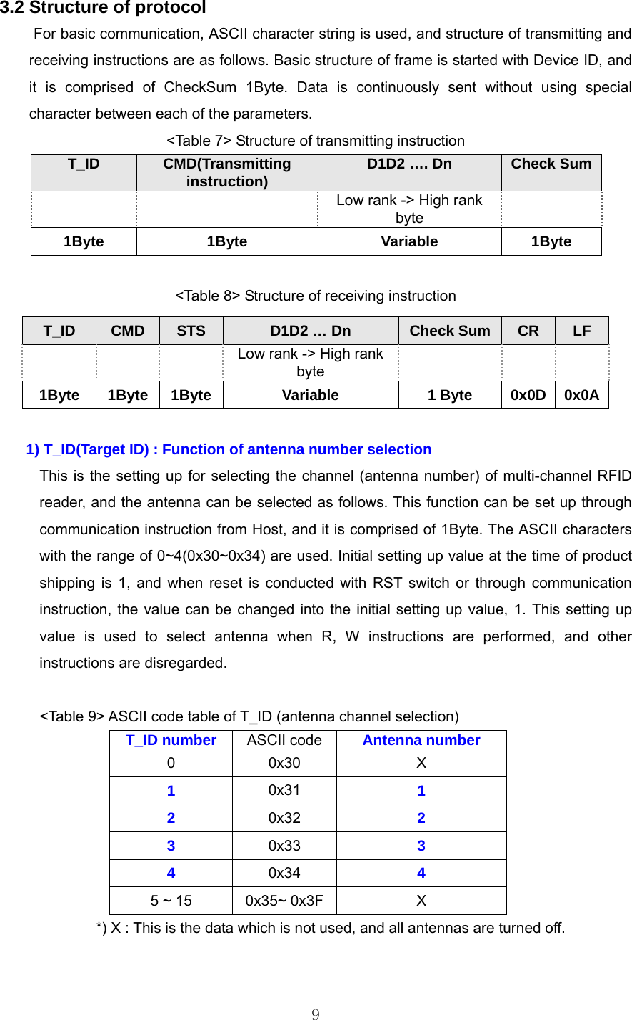
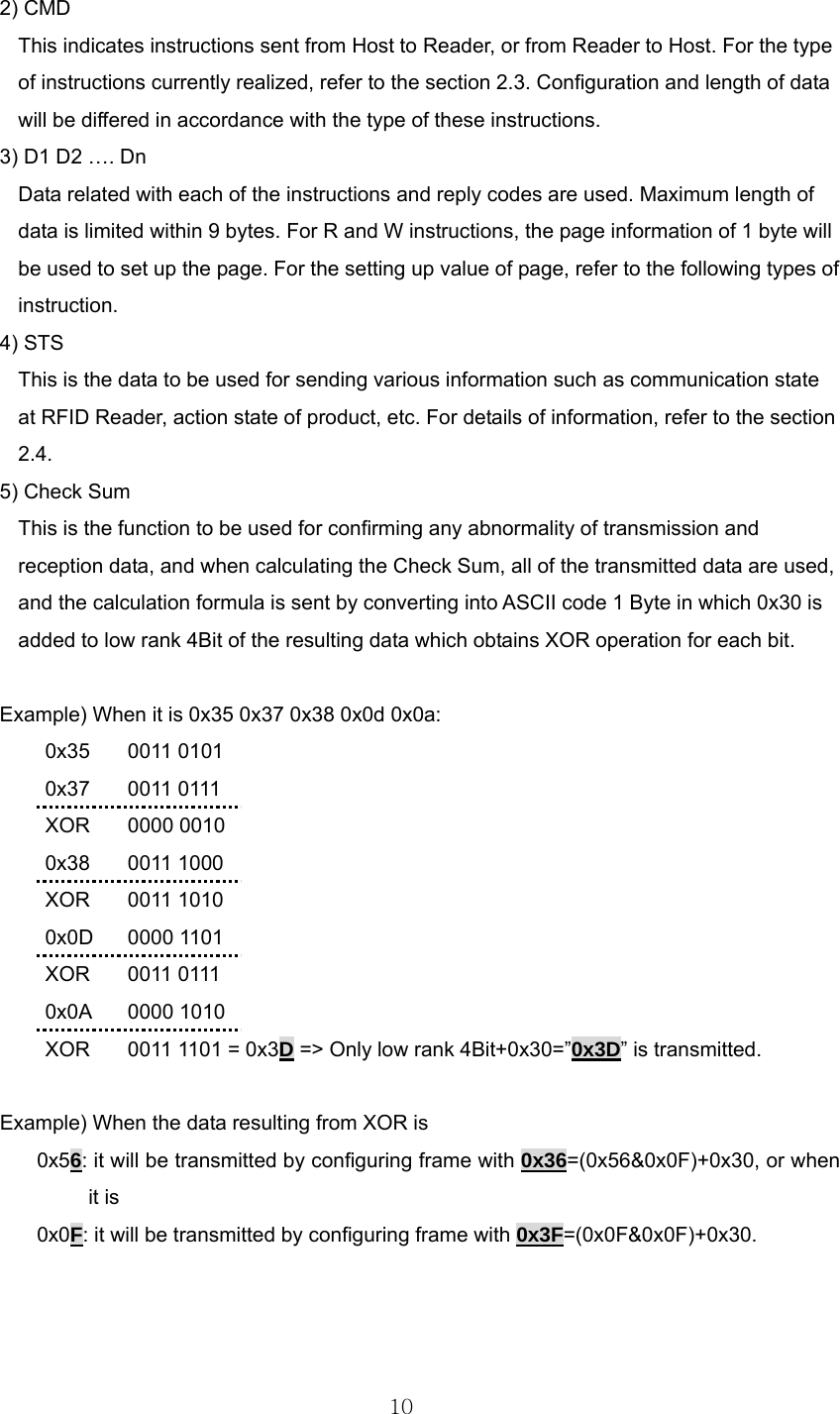
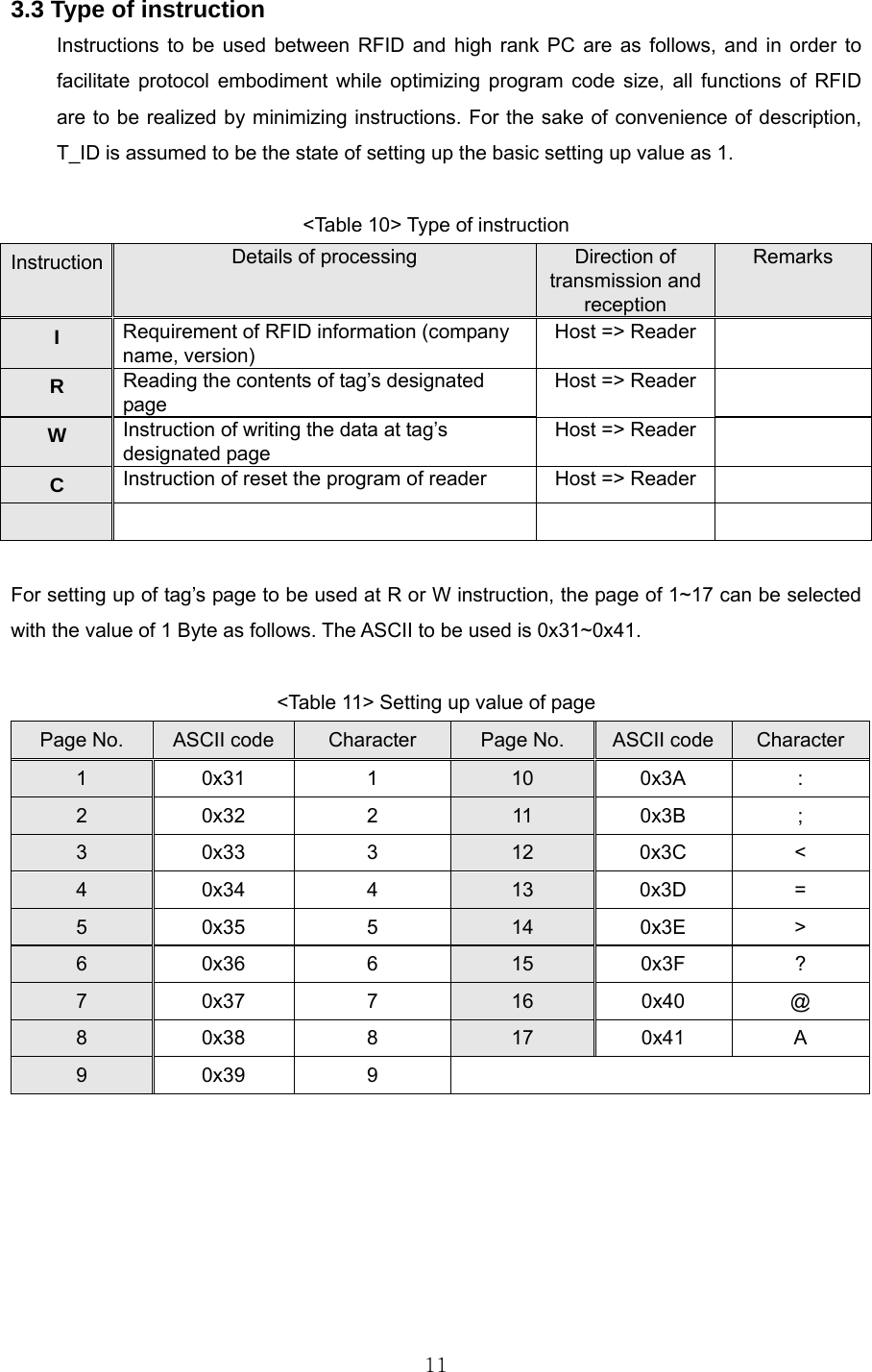
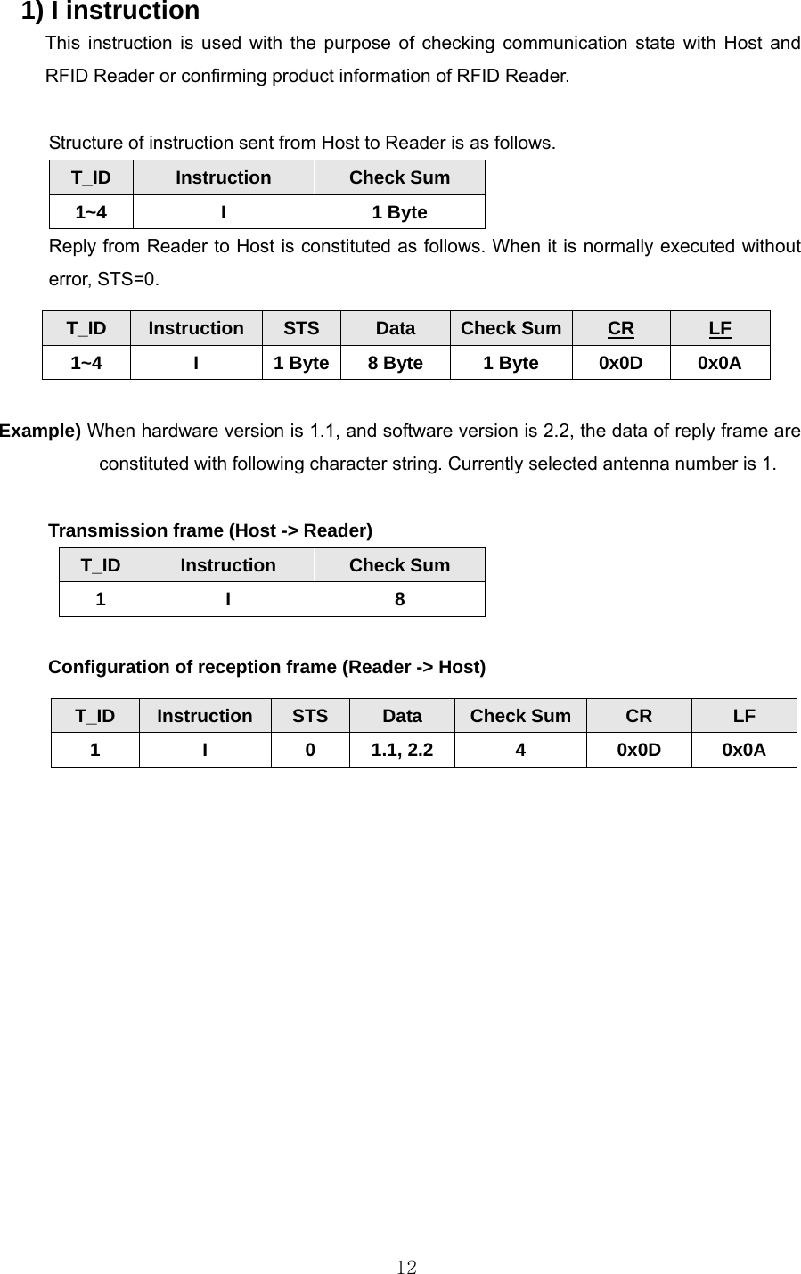
User Manual
Discussion / Help
Navigation