Users Manual

January 21, 2013
RFID Reader
(4 channel, Ethernet, 1st generation)
Operation manual
CTS-RFID-LF03 (V 1.3C)
2
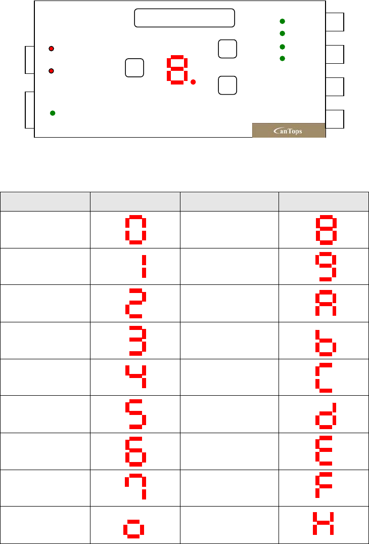
1. Descriptions of action for each part
1.1 ID number indicating section
In this product, 4 antennas can be conneted for use, and for the following 7 segments,
individual numbers of the antennas currently used are indicated. Initial value is set up as 1,
and if the setting up is to be changed, refer to the description of setting up section of the
following ID numbers.
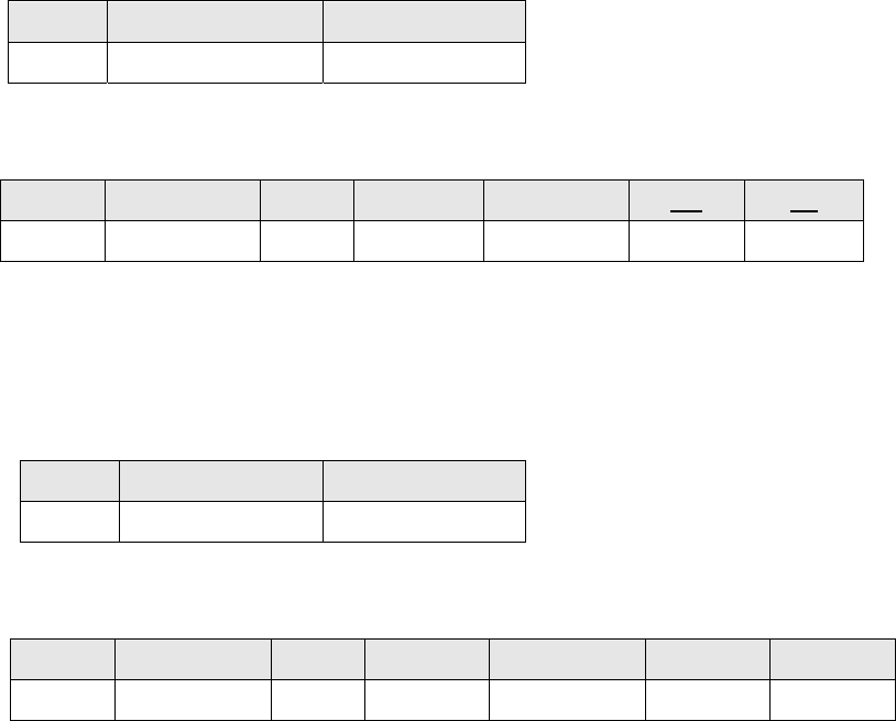
<Fig. 1> Outline drawing of RFID
<Table 1> Indicated details of 7 segments
ID No. Indicated details ID No. Indicated details
0
8
1
9
2
10
3
11
4
12
5
13
6
14
7
15
O(No error) X(Occurrence of
error)
ID No. RD
WR
RST
Tx
Rx
ANT4
Ethernet
Power
RFID Reader
ANT3
ANT2
ANT1

3
For the segment indicated with individual number, refer to the above <Table 1>. For the
range of ID number, 4 numbers can be set up with 1~4.
1.2 Setting up method of ID number
Setting up of ID number can be revised through communication at high rank controller. For
detailed information, refer to protocol specification.
1.3 Switch for tag test
In order to find optimum action condition when installing antennas of tag and RFID, it needs
to be confirmed whether the functions of reading and writing of tag are normally conducted
at RFID Reader. For these kinds of functional tests, RD (Read) and WR (Write) switches are
used. When pressing RD switch, if data is normally received by sending the reading
instruction to the tag, O. will be expressed at 7 segments for indicating ID No., and when
error is occurred, X. will be lighted. When WR switch is pressed with identical method,
abnormal state will be indicated after writing again the data value which has been read at
the tag. WR will basically be progressed only when there isn’t any abnormality after
conducting the reading test. In addition, WR button is combined with the function of
manually increasing the antenna number with the increment of 1. Therefore, when the
antenna number is changed, WR button is supposed to be pressed until the antenna with
desired number is selected. It shall be cautious that as this is acted together with WR
function, when this function is used, the information of tag’s last page can be changed into
an arbitrary data.
1.4 LED for indicating data transmitting and receiving state: Tx, Rx
When transmitting data from Host to RFID Reader, Rx LED is lighted, and when receiving,
Tx LED is lighted. Criteria of transmission and reception are judged with the basis of RFID
Reader.
1.5 Ethernet connector
RJ-45 connector is used, and pin specification is as following <Table 2>.
<Table 2> Specification of RJ45 connector
Pin
number
1 2 3 4 5 6 7 8
Function Tx+ Tx- Rx+ x x
Rx- x x
● Caution : This product must be used Shield Cable as Ethernet cable in order to satisfy
the FCC RULES.
4
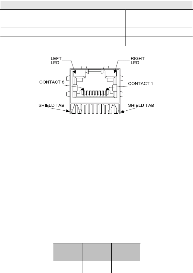
1.6 Indication details of Ethernet LED
When reviewing indication details of LED located at Ethernet connector, action status of
RFID reader can be grasped. Specific details of action are as follows.
Left LED (connection related indication) Right LED (action related indication)
Turned
off
Disconnected Turned off Action is not conducted
Amber 10MBPS Amber Half Duplex
Green 100MBPS Green Full Duplex
<Fig. 2> Photograph of Ethernet connector and LED action state
1.7 LED for indicating power
This is the LED activated when +24V power is supplied through power connector.
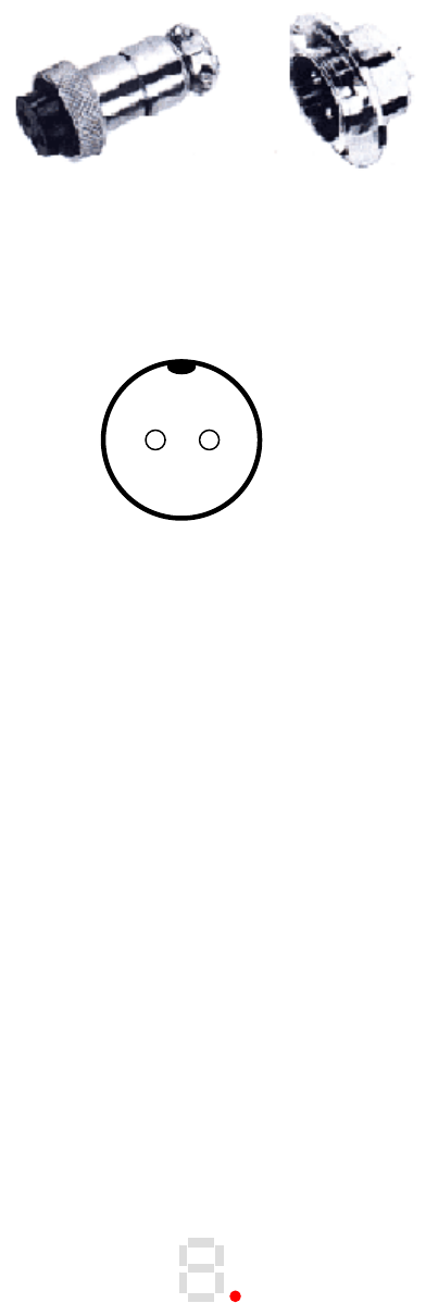
1.8 Power connector
Range of input voltage is 20~ 26V and specification of connector’s pin is as the following
<Table 4>. Connector to be used is SCK-12-2(R) of Samwoo Electronics, and the connector
at opposite side is SCK-12-2(P). Power shall always be supplied after connecting the power
connector, and when pulling out the power connector, it shall be done under the state of
power being turned off. If power connector is attached and detached under the state of
applied power, it can be the cause of damaging the parts.
<Table 4> Specification of power connector pin
Pin
number 1 2
Function +24V 24V GND
5
SCK-12-2(P) SCK-12-2(R)
<Fig. 3> Photograph of power connector
Arrangement of connector’s pin is as the following <Fig. 4>.
<Fig. 4> Arrangement of power connector pin
1. 9 ANT coupling connector
Antenna of RFID Reader is connected with BNC connector, and the antenna provided by
this company shall be used to have the best performance, and if a general type antenna is
connected, damage of product can be caused due to the abnormality generated at RF
related circuit.
1.10 Indication of abnormal states
When the CPU at RFID Reader inside is abnormally activated by external environment such
as static electricity, noise, and so forth, the dot of 7 segments shall be turned on as shown
in the <Fig. 5> as the function of indicating this. Normal action can be maintained by RFID
under the turned on state of this dot, however, if this phenomenon is continuously generated,
unsafe elements such as peripheral appliance, cable, and so forth shall be removed before
the use.
This dot will be turned off when RST, RD, or WR switch is pressed or when the power is
normally turned on again after turned it off.
<Fig. 5> Indication details of micom during its malfunction
1 2

6
1.11 Installation environment and specification of action
<Table 5> Installation environment of RFID
Classification Detailed item Description
Reader
Frequency 134.2KHz
Writing time 460mS/Page
Reading time 170mS/Page
Maximum reading
distance *Note1
90±5 mm
Maximum writing
distance
40±5mm
Number of channel 4 channels
Antenna
cable
(Option)
Diameter 3mm
Bending diameter 45mm
Length* Note 2 2m
Material PVC
Antenna
core section
(Option)
Size 62(Length)×13mm(Diameter), Tolerance: ±0.5mm
162(Length)×13mm(Diameter), Tolerance: ±0.5mm
Material Acetal, black color
Connector BNC
Type of tag RI-TRP-DR2B 17Page×64bit, Read/Write
Environment
Storing environment
Temperature: -25 ~ 70°C
Humidity: 5 ~ 95 %RH (However, no condensing
phenomenon)
Acting environment
Temperature: 0 ~ 50°C
Humidity:35~85 %RH (However, no condensing
phenomenon)
Power Input voltage DC 20V ~ 26V
Current consumption 50mA
Size (W×H×D) 176×93.4×30mm (Excluding protruded section of
connector)
Material of case SCP1(Steel)
Weight Approx. 430g
*Note 1) Characteristic of sensitivity will be differed in accordance with arrangement of Antenna
and Transponder, and this is the value measured under the state of eliminating outside
noise.
* Note 2) For changing the length of antenna cable and regarding the antenna with high
efficiency, please contact with our company.
7
2. Declaration of Conformity
2.1 Federal Communications Commission (FCC)
This device complies with Part 15 of the FCC Rules. Operation is subject to the following two
conditions:
1) This device may not cause harmful interference and
2) This device must accept any interference received, including interference that may cause
undesired operation.
FCC ID: RMN-CTS-RFID-LF03
WARNING STATEMENT
“Changes or modifications not expressly approved by the party responsible for compliance
could void the user's authority to operate the equipment.”
NOTE: This equipment has been tested and found to comply with the limits for a Class A
digital device, pursuant to part 15 of the FCC Rules.
These limits are designed to provide reasonable protection against harmful
interference when the equipment is operated in a commercial environment.
This equipment generates, uses, and can radiate radio frequency energy and, if not
installed and used in accordance with the instruction manual, may cause harmful
interference to radio communications.
Operation of this equipment in a residential area is likely to cause harmful nterference
in which case the user will be required to correct the interference at his own expense.
8
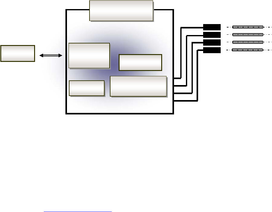
3. Specification of protocol
With this protocol, MID(Material ID) information can be read at the tag connected to RFID
Reader with RF by using Ethernet communication from the host, and various communication
parameters and so forth can be set up. An item to be cautious about communication with
RFID Reader is that if another instruction is sent while one received instruction is being
executed, all of the subsequent instructions will be disregarded. Therefore, 4 antennas can’t
read the tag simultaneously, but they can read one tag by one tag in sequence.
<Fig. 6> Configuration diagram of RFID system
3.1 Setting up of Ethernet port
The Ethernet function used for this product is connected to the Host through Ethernet by
using XPort of Lantronix (Ethernet to RS-232 converter), and it is connected to CPU with
asynchronous communication method through this converter. For detailed setting up and
using method related with Ethernet, refer to the technical data related with XPort of
Lantronix (http://www.lantronix.com). Most of setting up work can be conducted with
“DeviceInstaller_User Guide.pdf” of attached data, and for more detailed information, refer
to “XPort_User Guide.pdf”.
CPU
Transmission and
reception of RF
RFID Reader
Ethernet
to 232
Ethernet
Lo
g
ic
PC
Transponder
(Tag)
Antenna

9
3.2 Structure of protocol
For basic communication, ASCII character string is used, and structure of transmitting and
receiving instructions are as follows. Basic structure of frame is started with Device ID, and
it is comprised of CheckSum 1Byte. Data is continuously sent without using special
character between each of the parameters.
<Table 7> Structure of transmitting instruction
T_ID CMD(Transmitting
instruction) D1D2 …. Dn Check Sum
Low rank -> High rank
byte
1Byte 1Byte Variable 1Byte
<Table 8> Structure of receiving instruction
1) T_ID(Target ID) : Function of antenna number selection
This is the setting up for selecting the channel (antenna number) of multi-channel RFID
reader, and the antenna can be selected as follows. This function can be set up through
communication instruction from Host, and it is comprised of 1Byte. The ASCII characters
with the range of 0~4(0x30~0x34) are used. Initial setting up value at the time of product
shipping is 1, and when reset is conducted with RST switch or through communication
instruction, the value can be changed into the initial setting up value, 1. This setting up
value is used to select antenna when R, W instructions are performed, and other
instructions are disregarded.
<Table 9> ASCII code table of T_ID (antenna channel selection)
T_ID number ASCII code Antenna number
0 0x30 X
1 0x31 1
2 0x32 2
3 0x33 3
4 0x34 4
5 ~ 15 0x35~ 0x3F X
*) X : This is the data which is not used, and all antennas are turned off.
T_ID CMD STS D1D2 … Dn Check Sum CR LF
Low rank -> High rank
byte
1Byte 1Byte 1Byte Variable 1 Byte 0x0D 0x0A

10
2) CMD
This indicates instructions sent from Host to Reader, or from Reader to Host. For the type
of instructions currently realized, refer to the section 2.3. Configuration and length of data
will be differed in accordance with the type of these instructions.
3) D1 D2 …. Dn
Data related with each of the instructions and reply codes are used. Maximum length of
data is limited within 9 bytes. For R and W instructions, the page information of 1 byte will
be used to set up the page. For the setting up value of page, refer to the following types of
instruction.
4) STS
This is the data to be used for sending various information such as communication state
at RFID Reader, action state of product, etc. For details of information, refer to the section
2.4.
5) Check Sum
This is the function to be used for confirming any abnormality of transmission and
reception data, and when calculating the Check Sum, all of the transmitted data are used,
and the calculation formula is sent by converting into ASCII code 1 Byte in which 0x30 is
added to low rank 4Bit of the resulting data which obtains XOR operation for each bit.
Example) When it is 0x35 0x37 0x38 0x0d 0x0a:
0x35 0011 0101
0x37 0011 0111
XOR 0000 0010
0x38 0011 1000
XOR 0011 1010
0x0D 0000 1101
XOR 0011 0111
0x0A 0000 1010
XOR 0011 1101 = 0x3D => Only low rank 4Bit+0x30=”0x3D” is transmitted.
Example) When the data resulting from XOR is
0x56: it will be transmitted by configuring frame with 0x36=(0x56&0x0F)+0x30, or when
it is
0x0F: it will be transmitted by configuring frame with 0x3F=(0x0F&0x0F)+0x30.

11
3.3 Type of instruction
Instructions to be used between RFID and high rank PC are as follows, and in order to
facilitate protocol embodiment while optimizing program code size, all functions of RFID
are to be realized by minimizing instructions. For the sake of convenience of description,
T_ID is assumed to be the state of setting up the basic setting up value as 1.
<Table 10> Type of instruction
Instruction Details of processing Direction of
transmission and
reception
Remarks
I Requirement of RFID information (company
name, version)
Host => Reader
R Reading the contents of tag’s designated
page
Host => Reader
W Instruction of writing the data at tag’s
designated page
Host => Reader
C Instruction of reset the program of reader Host => Reader
For setting up of tag’s page to be used at R or W instruction, the page of 1~17 can be selected
with the value of 1 Byte as follows. The ASCII to be used is 0x31~0x41.
<Table 11> Setting up value of page
Page No. ASCII code Character Page No. ASCII code Character
1 0x31 1 10 0x3A :
2 0x32 2 11 0x3B ;
3 0x33 3 12 0x3C <
4 0x34 4 13 0x3D =
5 0x35 5 14 0x3E >
6 0x36 6 15 0x3F ?
7 0x37 7 16 0x40 @
8 0x38 8 17 0x41 A
9 0x39 9
12
1) I instruction
This instruction is used with the purpose of checking communication state with Host and
RFID Reader or confirming product information of RFID Reader.
Structure of instruction sent from Host to Reader is as follows.
T_ID Instruction Check Sum
1~4 I 1 Byte
Reply from Reader to Host is constituted as follows. When it is normally executed without
error, STS=0.
Example) When hardware version is 1.1, and software version is 2.2, the data of reply frame are
constituted with following character string. Currently selected antenna number is 1.
Transmission frame (Host -> Reader)
T_ID Instruction Check Sum
1 I 8
Configuration of reception frame (Reader -> Host)
T_ID Instruction STS Data Check Sum CR LF
1~4 I 1 Byte 8 Byte 1 Byte 0x0D 0x0A
T_ID Instruction STS Data Check Sum CR LF
1 I 0 1.1, 2.2 4 0x0D 0x0A

13
2) R instruction
This is the instruction for reading the details of tag’s designated number of address, and the
tag currently used has the memory of 17 Page(8Byte/Page) with which reading and writing
can be conducted. Since the basic unit of reading and writing the data at the tag is the page,
it is desirable to process with 8Byte of page unit when reading and writing the tag at high
rank computer.
Structure of instruction sent from Host to Reader is as follows.
Reply from Reader to Host is constituted as follows. When it is normally executed without
error, STS=0.
Example) When the data of ‘66666666’ is stored at 6 Page of tag whose T_ID=1, if the data is
read with R instruction, the transmission and reception frame are constituted as
follows.
Transmission frame (Host -> Reader)
T_ID Instruction Page Check Sum
1 R 6 5
Configuration of reception frame (Reader -> Host)
T_ID Instruction Page Check Sum
1~4 R 1~A(1 Byte) 1 Byte
T_ID Instruction STS Data Check Sum CR LF
1~4 R 0 8 Byte 1 Byte 0x0D 0x0A
T_ID Instructi
on
STS Data(8 Byte) Check Sum CR LF
1 R 0 66666666 3 0x0D 0x0A

14
3) W instruction
This is the instruction of writing data at designated page of tag, and the configuration of
transmission and reception frame is as follows.
Structure of instruction sent from Host to Reader is as follows.
Reply from Reader to Host is constituted as follows. When it is normally executed without error,
STS=0. In addition, at data field, the data sent from Host is returned.
Example) When writing ‘12345678’ at 1 Page of the tag whose T_ID=1, the transmission and
reception frame are constituted as follows.
Transmission frame (Host -> Reader)
Configuration of reception frame (Reader -> Host)
T_ID Instruction Page Data Check Sum
1~4 W 1~A (1 Byte) 8 Byte 1 Byte
T_ID Instruction STS Data Check Sum CR LF
1~4 W 0 8 Byte 1 Byte 0x0D 0x0A
T_ID Instruction Page Data Check Sum
1 W 1 12345678 ?
T_ID Instruction STS Data Check Sum CR LF
1 W 0 12345678 > 0x0D 0x0A

15
4) C instruction
This is the instruction of resetting the program of reader, and T_ID is initialized as No.1, and
outside sensor action mode is initialized as Disable mode, and the address of automatic
reading mode by sensor is initialized as 01 number of address where MID is stored. All
setting up values will be activated with new setting values from the next instruction after
sending the reply by C instruction.
Structure of instruction sent from Host to Reader is as follows.
Reply from Reader to Host is constituted as follows. When it is normally executed without error,
STS=0.
Example) When resetting RFID Reader whose T_ID=1 to initial state, the transmission and
reception data will be as follows.
Transmission frame (Host -> Reader)
Configuration of reception frame (Reader -> Host)
T_ID Instruction Check Sum
1~4 C 1 Byte
T_ID Instruction STS Check Sum CR LF
1~4 C 0 1 Byte 0x0D 0x0A
T_ID Instruction Check Sum
1 C 2
T_ID Instruction STS Check Sum CR LF
1 C 0 2 0x0D 0x0A

16
5) Reply code when communication errors are generated
When communication error or serious error is generated at RFID Reader, data will be sent to
host with following constitution of frame. The value of 0x31~0x38 will be returned to STS.
3.4 Type of status
As shown in the following Table, the status is comprised of 1 Byte.
<Table 13> Type of status
Code Status Remarks
‘0’ When received data does not have abnormality and instruction is
normally executed
‘1’ For received date, parity and check sum have abnormality
‘2’ Instruction with different or without T_ID number is received
‘3’ When received data is too long (Maximum 12Byte)
‘4’ When writing the data at the tag is failed
‘5’ When there is no tag
‘6’ If check sum error is generated at the tag when the type of the tag is
different from that of received instruction’s tag
‘7’ When received instruction cannot be executed under the status of set up
variable, i.e., the value of variable has an abnormality
‘8’ Communication error with tag
T_ID STS Check Sum
1 1~8 1 Byte

17
4. Type of tag
The tag currently used has the memory of 17 Page(8Byte/Page) with which reading and
writing can be conducted. Since the basic unit of reading and writing the data at the tag is the
page, it is desirable to process with 8Byte of page unit when reading and writing the tag at high
rank appliance. Each of the pages is constituted as following shape.
<Table 14> Type of tag
Page number Application Remarks
1 Low rank 8Byte of Material ID MID information
2 High rank 8Byte of Material ID
3~17 The area for reading and writing freely of fair
information
NotePad area
When using the tag with different shape, it can be used with the revision of firmware.
18
5. Installation method of ANT
5.1 Specification of ANT
PVC is used as outer shell material, and length and thickness of cable can be changed in
accordance with ordered specification, however, it is desirable to use the cable within the
maximum length of 5 m. For the antenna to be used in this reading device, the two types of
antennas shown in the following <Table 15> can be used as the standard, and the antenna
with special specification can separately be manufactured. For the 162mm antenna, it will
be the good antenna with fine reading performance when the tag is vertically placed at the
side of the antenna rather than the one with the structure shown in the <Fig. 8>.
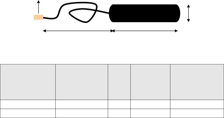
<Fig. 7> Dimension of circular antenna
<Table 15> Characteristic for each type of antenna
Type of antenna Name of item
Recogn
ition
distanc
e
Characteristic
(Noise
environment)
Example of use
62mm Stick CTS-RFID-ANxx 90mm Excellent Stocker
162mm Stick CTS-RFID-ALxx 85mm Ordinary OHT
The xx under the name of item of <Table 15> means the length with the unit of 10cm, and it is
limited in the range from 01, which is 0.1m, to the maximum of 50, which is 5m.
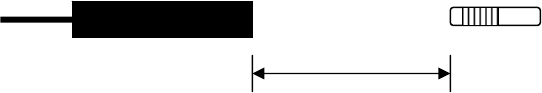
Recognition distance means the straight distance between the antenna end to tag as shown in
the <Fig. 8>. The data measured under no-noise environment can be different from the one
measured under actual using environment.
62mm
13mm
2M
BNC connector
19
<Fig. 8> Standard of recognition distance
Recognition distance
20
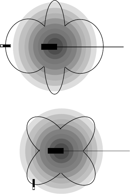
5.2 Setting up method of optimum location
1) As in the <Fig. 9-A>, the longest recognition distance can be used for the case of
confronting the antenna of RFID Reader and the tag face-to-face with each other, and
when the direction is deviated, the recognition distance will be shortened.
2) In order to prevent malfunction by the noise radiated from peripheral devices, installation
shall be conducted so that interference with monitor, switching relay, adjacent
transponder (tag), and so forth will not be generated. During the installation, if the noise
source in the vicinity is located and eliminated, recognition distance and speed can
largely be enhanced.
3) During the installation, it shall be careful not to have metallic part in the vicinity of antenna
and tag. If there is any metallic part in the surroundings, recognition distance can be
shortened due to the generation of abnormality at RF signal created from the antenna.
Therefore, even in the case of the fixtures securing antenna, it is desirable for them to
be processed with insulation material like acetal, and if existence of stainless steel or
aluminum in the surroundings is unavoidable, the antenna with special shape or
shielding method shall be required.
(A) When antenna and tag are in the same axis
(B) When antenna and tag are perpendicular with each other
<Fig. 9> Recognition distance (Read) in accordance with arrangement of antenna and tag
21
5.3 Recognition distance
In order to raise recognition distance, locations of Tag and RFID Reader shall be arranged
on a horizontal line, and it shall be careful not to make other metallic items placed near to the
antenna and tag during installation. <Fig. 8> is a schematic which indicates the recognition
distance in accordance with the arrangement of antenna and tag, and the most desirable
arrangement is the one when the antenna and tag are placed on a same axis, and if they are
placed in vertical arrangement, the tag is desirable to be installed not at the center but at the
end section of the antenna body. For recognition distance, securing sufficient allowance is
required, therefore, the allowance of recognition distance shall always be confirmed under the
arranged state while testing normal reading state with read switch of the reader.
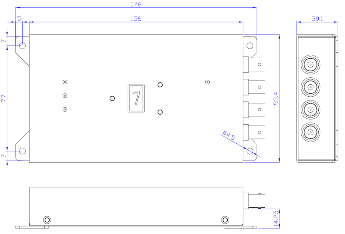
< Attachment> Specification of RFID Reader Case
Unit : mm
23
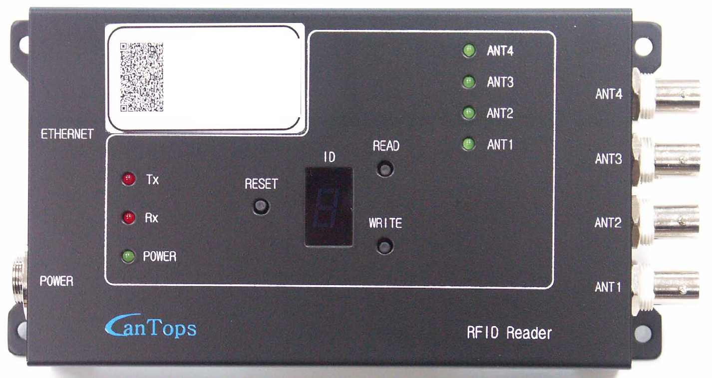
< Attachment> Photograph of RFID Reader
제품명 Name of product
모델명 Name of model
제조일 Date of manufacture
제조사 Manufacturer
Name of Product : RFID Reader
Name of Model : CTS-RFID-LF03
S/N : RL-40003
Date of Manufacturer: Oct. 05, 2007
Manufacturer : CanTops
00-20-4A-8F-47-E3