CARRIER Controls And HVAC Accessories Manual L0210306
User Manual: CARRIER CARRIER Controls and HVAC Accessories Manual CARRIER Controls and HVAC Accessories Owner's Manual, CARRIER Controls and HVAC Accessories installation guides
Open the PDF directly: View PDF ![]() .
.
Page Count: 16
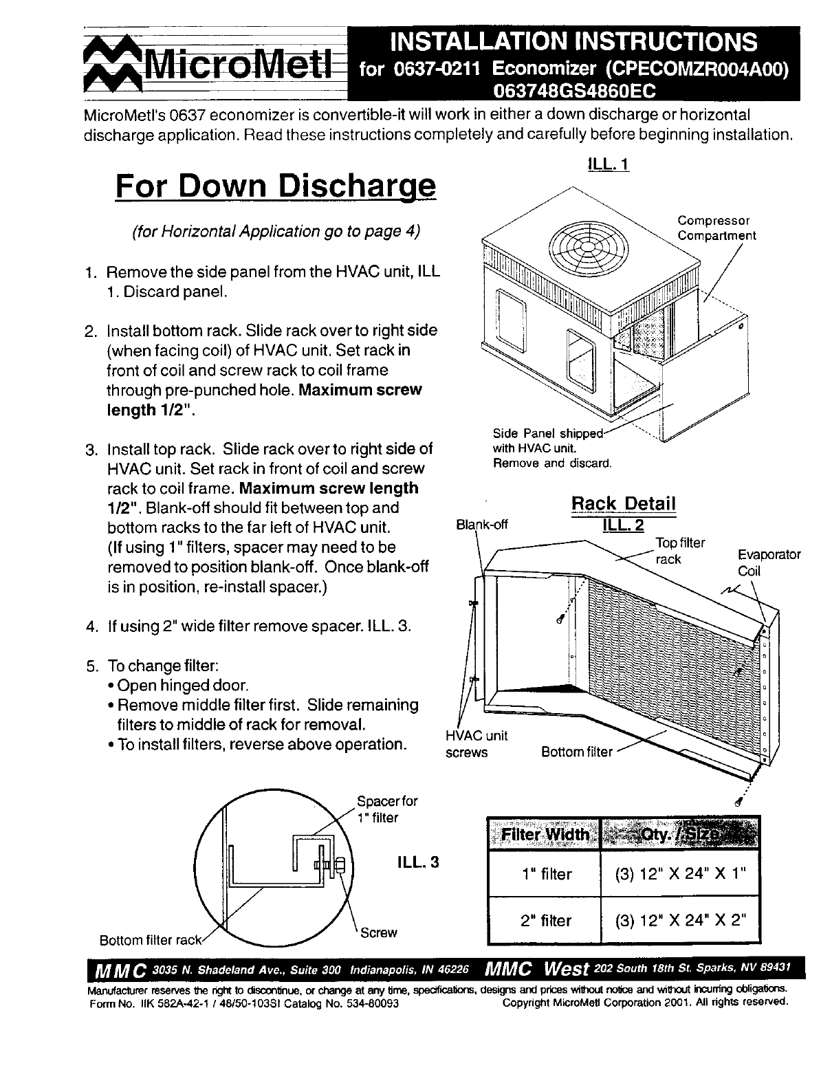
MicroMetl's 0637 economizer is convertible-it will work in either a down discharge or horizontal
discharge application. Read these instructions completely and carefully before beginning installation•
ILL. 1
For Down Discharge
(for Horizontal Application go to page 4) Compressor
Compartment
1. Remove the side panel from the HVAC unit, ILL
1. Discard panel.
2. Install bottom rack. Slide rack over to right side
(when facing coil) of HVAC unit. Set rack in
front of coil and screw rack to coil frame
through pre-punched hole. Maximum screw
length 1/2".
3. Install top rack. Slide rack over to right side of
HVAC unit. Set rack in front of coil and screw
rack to coil frame. Maximum screw length
1/2". Blank-off should fit between top and
bottom racks to the far left of HVAC unit.
(If using 1" filters, spacer may need to be
removed to position blank-off. Once blank-off
is in position, re-install spacer.)
4. If using 2" wide filter remove spacer. ILL. 3.
5. To change filter:
• Open hinged door.
• Remove middle filter first. Slide remaining
filters to middle of rack for removal.
• To install filters, reverse above operation.
Spacerfor
Side Panel
with HVAC unit.
Remove and discard•
Rack Detail
Blank-off ILL. 2
_ jTop filter Evaporator
HVAC unit
screw BoSom filter/- __
#"
Bo_o
ILL. 3
Screw
1" filter
2" filter
(3) 12" X 24" X 1"
(3) 12" X 24" X 2"
Manufacturer reserves the right to disconlJnue,or change at any IJrne,specificaf_ns, designs and pnces withoutno'dceand without incurnngobliga_ons.
Form No. IlK 582A-42-1 /48/50-10381 Catalog No. 534-80093 Copyright MicroMetl Corporation 2001. All fights reserved.
ILL.5
Install additional screw
'l unit flange into
replacement panel.
MicroMetl
1/2" flange
Install 3/4" x1/8 28 _/2"
gasket along
economizer bottom
Replacement panel.
Shipped with
economizer
Install 3/4" x 1/8"
gasket along
flange
3/8" " -. I
Economizer
cover panel
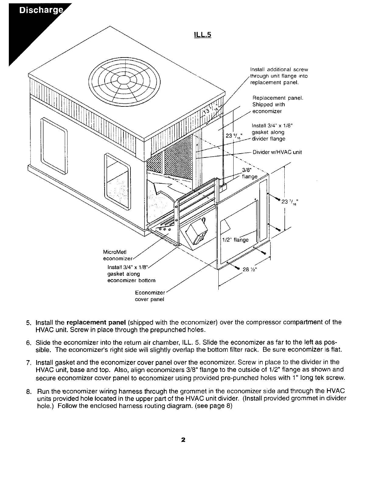
5. Install the replacement panel (shipped with the economizer) over the compressor compartment of the
HVAC unit. Screw in place through the prepunched holes.
6. Slide the economizer into the return air chamber, ILL. 5. Slide the economizer as far to the left as pos-
sible. The economizer's right side will slightly overlap the bottom filter rack. Be sure economizer is flat.
7. Install gasket and the economizer cover panel over the economizer. Screw in place to the divider in the
HVAC unit, base and top. Also, align economizers 3/8" flange to the outside of 1/2" flange as shown and
secure economizer cover panel to economizer using provided pre-punched holes with 1" long tek screw.
8. Run the _economizer wiring harness through the grommet in the economizer side and through the HVAC
units provided hole located in the upper part of the HVAC unit divider. (Install provided grommet in divider
hole.) Follow the enclosed harness routing diagram. (see page 8)
2
g,
11.
12,
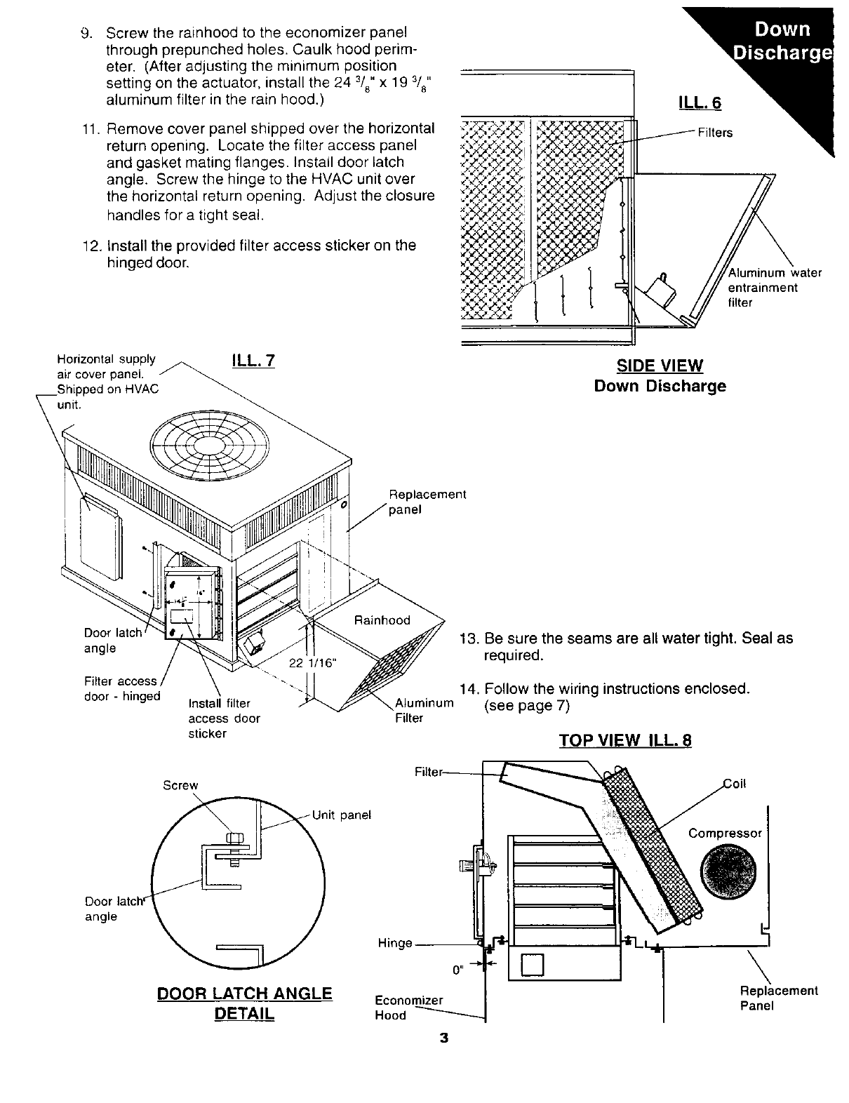
Screw the rainhood to the economizer panel
through prepunched holes. Caulk hood perim-
eter. (After adjusting the minimum position
setting on the actuator, install the 24 3/8" x 19 3/8"
aluminum filter in the rain hood.)
Remove cover panel shipped over the horizontal
return opening. Locate the filter access panel
and gasket mating flanges. Install door latch
angle, Screw the hinge to the HVAC unit over
the horizontal return opening. Adjust the closure
handles for a tight seal.
Install the provided filter access sticker on the
hinged door. kluminum water
entrainment
filter
Horizontal supply A ILL. 7
air cover panel. /" _ -
HVAC_
SIDE VIEW
Down Discharge
Replacement
Door latch
angle
Filter access
door - hinged Install filter
access door
sticker
Aluminum
Filter
13. Be sure the seams are all water tight. Seal as
required.
14. Follow the wiring instructions enclosed.
(see page 7)
TOP VIEW ILL. 8
Door
angle
Screw
DOOR LATCH ANGLE
DETAIL
panel
Hinge
Economizer
Hood
3
[]
Compressor
\
Replacement
Panel
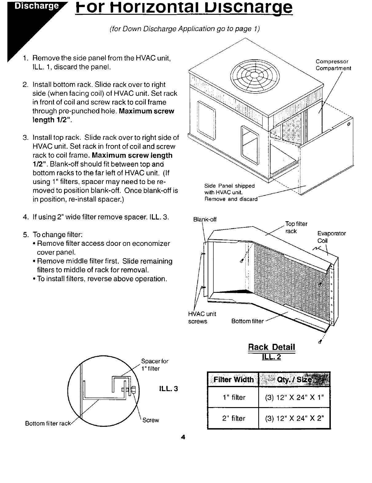
l-or I-IOrlzonl:al Ulscnarg_e_
(for Down Discharge Application go to page 1)
1. Remove the side panel from the HVAC unit,
ILL. 1, discard the panel.
2. Install bottom rack. Slide rack over to right
side (when facing coil) of HVAC unit. Set rack
in front of coil and screw rack to coil frame
through pre-punched hole. Maximum screw
length 1/2".
3. Install top rack. Slide rack over to right side of
HVAC unit. Set rack in front of coil and screw
rack to coil frame. Maximum screw length
1/2". Blank-off should fit between top and
bottom racks to the far left of HVAC unit. (If
using 1" filters, spacer may need to be re-
moved to position blank-off. Once blank-off is
in position, re-install spacer.)
Side Panel shipped
with HVAC unit,
Remove and discard
Compressor
Compartment
4. If using 2" wide filter remove spacer. ILL. 3.
5. To change filter:
•Remove filter access door on economizer
cover panel.
• Remove middle filter first. Slide remaining
filters to middle of rack for removal.
• To install filters, reverse above operation.
Spacerfor
ILL. 3
BoSom
Blank-off Top filter
\ __ ..
"/ /'-_--_ ""->_ rack Evaporator
HVAC unit
s( _ws Bo_orn filter/- -_--_,..-_q_
#"
Rack Detail
ILL. 2
4
Filter Wiath
1" filter
2" filter
(3) 12" X 24" X 1"
(3) 12" X 24" X 2"
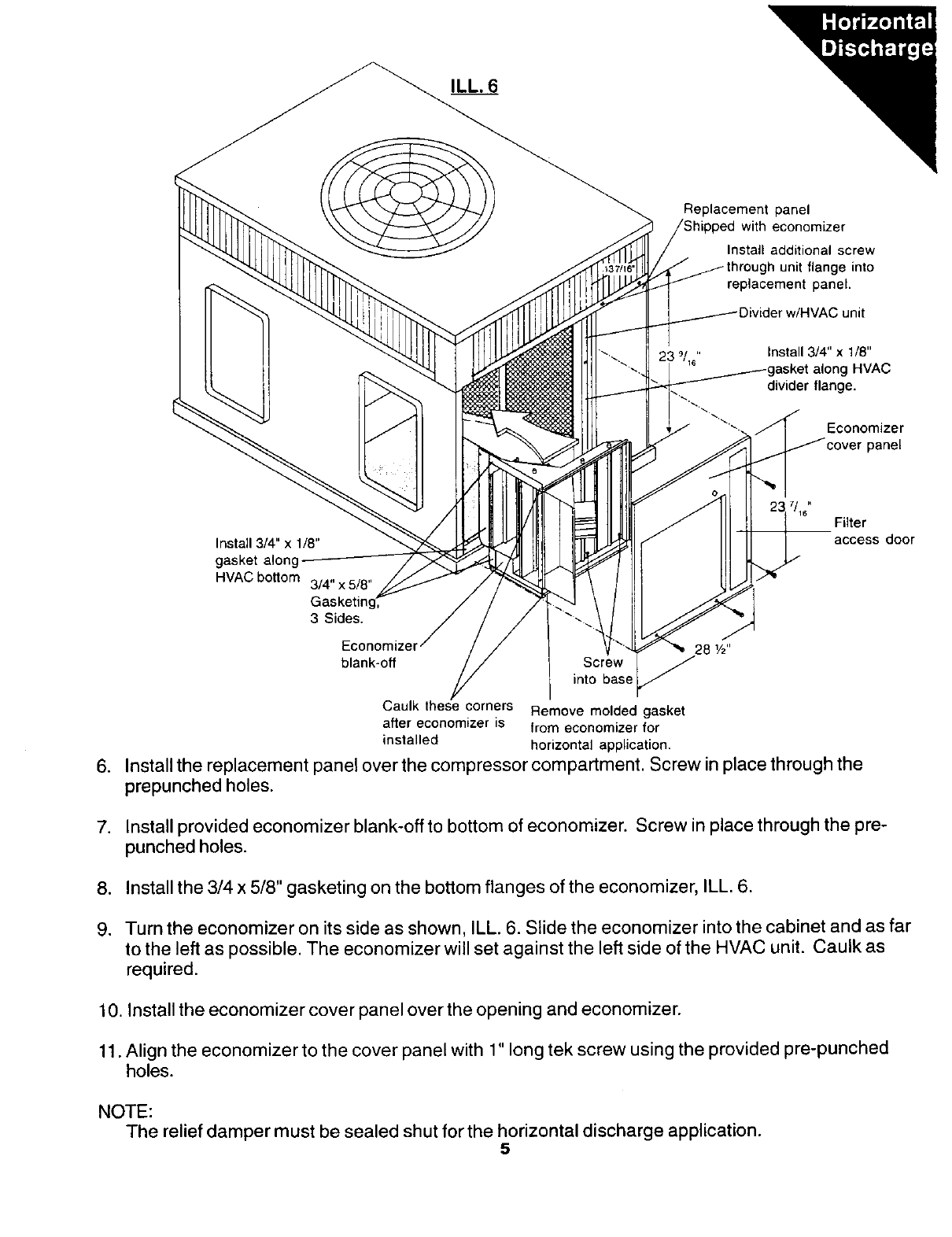
ILL. 6
Replacement panel
with economizer
Install additional screw
unit flange into
replacement panel.
;unit
9,, Install 3/4" x 1/8"
asket along HVAC
divider flange.
Economizer
panel
Install 3/4" x 1/8"
gasket
HVAC bottom 3/4" x 5/8"
Casketing,
3 Sides.
7.
/16 Filter
access door
blank-off
Caulk these corners
after economizer is
installed
28 1/2"
Screw _
nto base
Remove molded gasket
from economizer for
horizontal application.
6. Install the replacement panel over the compressor compartment. Screw in place through the
prepunched holes.
7. Install provided economizer blank-offto bottom of economizer. Screw in place through the pre-
punched holes.
8. Install the 3/4 x 5/8" gasketing on the bottom flanges of the economizer, ILL. 6.
9. Turn the economizer on its side as shown, ILL. 6. Slide the economizer into the cabinet and as far
to the left as possible. The economizer will set against the left side of the HVAC unit. Caulk as
required.
10. Install the economizer cover panel over the opening and economizer.
11. Align the economizer to the cover panel with 1" long tek screw using the provided pre-punched
holes.
NOTE:
The relief damper must be sealed shut for the horizontal discharge application.
5
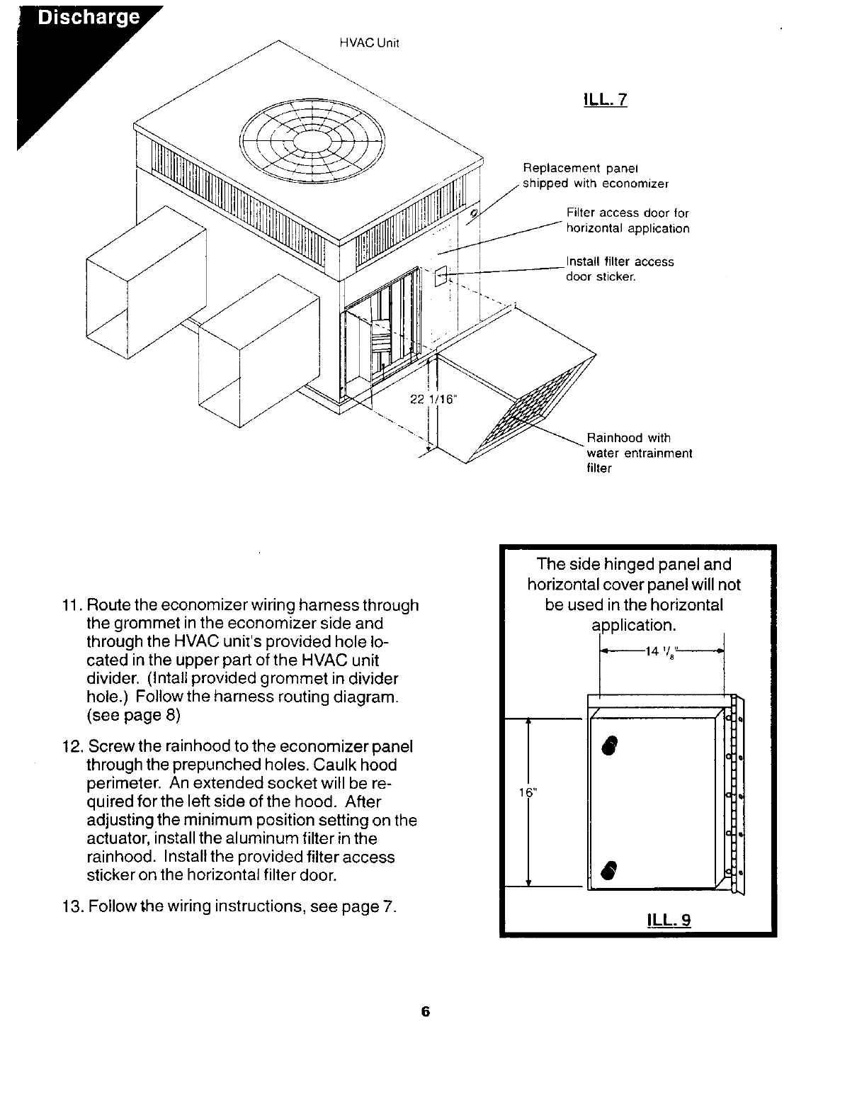
HVAC Unit
ILL. 7
Replacement panel
with economizer
Filter access door for
Lpplieation
Install filter access
door sticker.
Rainhood with
water entrainment
filter
11. Route the economizer wiring harness through
the grommet in the economizer side and
through the HVAC unit's provided hole lo-
cated in the upper part of the HVAC unit
divider. (Intall provided grommet in divider
hole.) Followthe harness routing diagram.
(see page 8)
12. Screw the rainhood to the economizer panel
through the prepunched holes. Caulk hood
perimeter. An extended socket will be re-
quired for the left side of the hood. After
adjusting the minimum position setting on the
actuator, install the aluminum filter in the
rainhood. Install the provided filter access
sticker on the horizontal filter door.
13. Follow _he wiring instructions, see page 7.
iThe side hinged panel and
ihorizontal cover panel will not
| be used in the horizontal
iapplicationl,
6
Equipment
Transformer Yellow
Brown
Green
White
Main24V
SpliceBox
0
_. Gr_..Lr
[
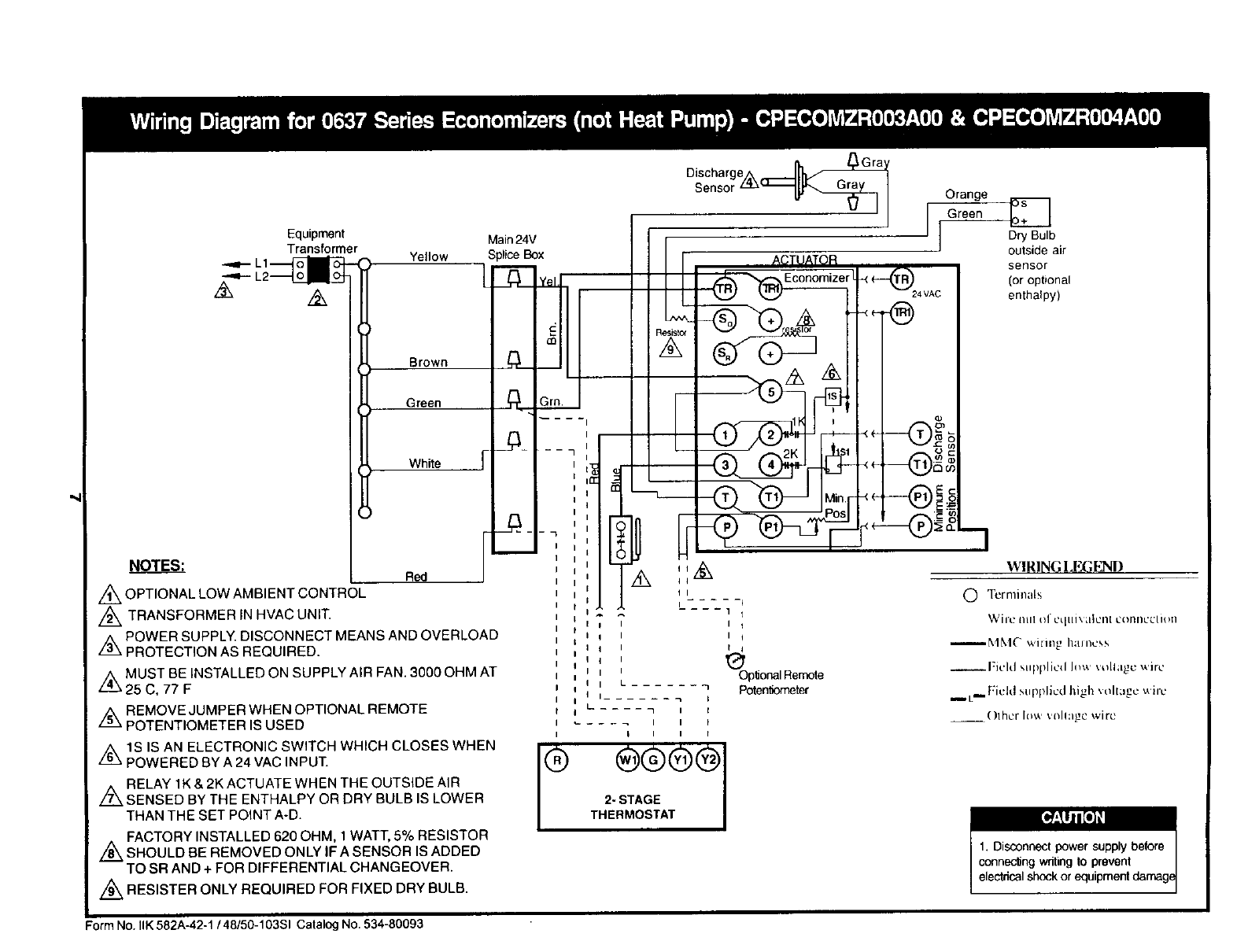
NOTES: Red
/'_ OPTIONAL LOW AMBIENT CONTROL
//_ TRANSFORMER IN HVAC UNIT.
Z_ POWER SUPPLY. DISCONNECT MEANS AND OVERLOAD
PROTECTION AS REQUIRED.
z_ MUST BE INSTALLED ON SUPPLY AIR FAN. 3000 OHM AT
25 C, 77 F
/.k REMOVE JUMPER WHEN OPTIONAL REMOTE
POTENTIOMETER IS USED
z_IS IS AN ELECTRONIC SWITCH WHICH CLOSES WHEN
POWERED BY A 24 VAC INPUT.
Z_ RELAY 1K & 2K ACTUATE WHEN THE OUTSIDE AIR
SENSED BY THE ENTHALPY OR DRY BULB IS LOWER
THAN THE SET POINT A-D.
Z_ FACTORY INSTALLED 620 OHM, 1 WATT, 5% RESISTOR
SHOULD BE REMOVED ONLY IF ASENSOR IS ADDED
TO SR AND + FOR DIFFERENTIAL CHANGEOVER.
/_ RESISTER ONLY REQUIRED FOR FIXED DRY BULB.
_Gra
DischargeA
Sensor ____ Orange
Green _]
J[ Dry Bulb
outside air
sensor
(or optional
enthalpy)
..... i
.... 1 t
It
It
OplJonalRemote
'Poteni]ometer
Form No. IlK 582A-42-1 /48/50-103SI Catalog No. 534-80093
GO
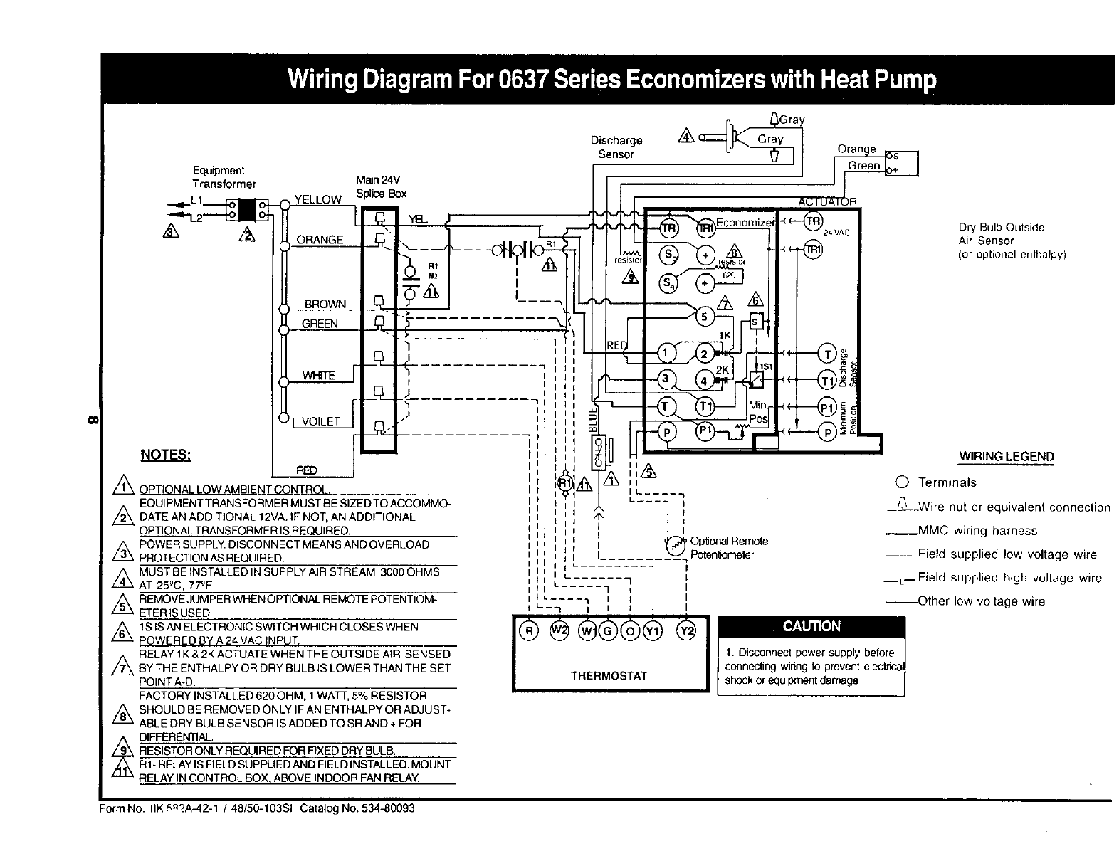
NOTES:
Equipment
Transformer
Ax D_ Bulb Outside
Air Sensor
(or optional enthalpy)
WIRING LEGEND
(_ Terminals
Z_ OPTIONAL LOW AMBIENT CONTROL.
EQUIPMENTTRANSFORMERMUSTBESIZEDTOACCOMMO- ___Wire nut or equivalent connection
z_ DATE AN ADDITIONAL 12VA. IF NOT, AN ADDITIONAL
OPTIONALTRANSFORMERISREQUIRED. __MMC wiring harness
-- Field supplied low voltage wire
n, _Gray
Sensor
Main 24V
AC FUAIOR
,YEtLOW [IT,
III IZI : III I
n. ',',,,,',
Ill,,I I I
m_il II I
ItJ U II
iILJL_ II
I,, _._Z!__Im ',k.....
,,,,, ,:, ;;
I
iii l 4% ] I
lli I I
1,I ', I , 1 _ Op'donal Remote
iI tl Ii '1[;....... _ Poten_neler
i I
Ill Le- ...... -I I [
Z_ POWER SUPPLY. DISCONNECT MEANS AND OVERLOAD
PROTECTION AS REQUIRED.
Z_ MUST BE INSTALLED IN SUPPLY AIR STREAM. 3000 OHMS
AT 25_C, 77eF
Z_ REMOVE JUMPER WHEN OPTIONAL REMOTE POTENTIOM-
ETER IS USED
/_ lS IS ANELECTRONIC SWITCH WHICH CLOSES WHEN
POWERED BY A 24 VAC INPUT.
//_ RELAY 1K & 2K ACTUATE WHEN THE OUTSIDE AIR SENSED
BY THE ENTHALPY OR DRY BULB IS LOWER THAN THE SET
POINT A-D.
FACTORY INSTALLED 620 OHM. 1 WATF, 5% RESISTOR
,_ SHOULD BE REMOVED ONLY IF AN ENTHALPY OR ADJUST-
ABLE DRY BULB SENSOR IS ADDED TO SR AND + FOR
_ DIFFERENTIAL
RESISTOR ONLY REQUIRED FOR FIXED DRY BULB.
R1- RELAY IS FIELD SUPPLIED AND FIELD INSTALLED. MOUNT
RELAY IN CONTROL BOX, ABOVE INDOOR FAN RELAY
__L--Field supplied high voltage wire
lel ...... q _ i I
IIL.... 1 III I--Other low voltage wire
I L---I IIII I
THERMOSTAT I shock or equipment damage
Form No. IlK £.n_.A-42-1 /48/50-103SI Catalog No. 534-80093
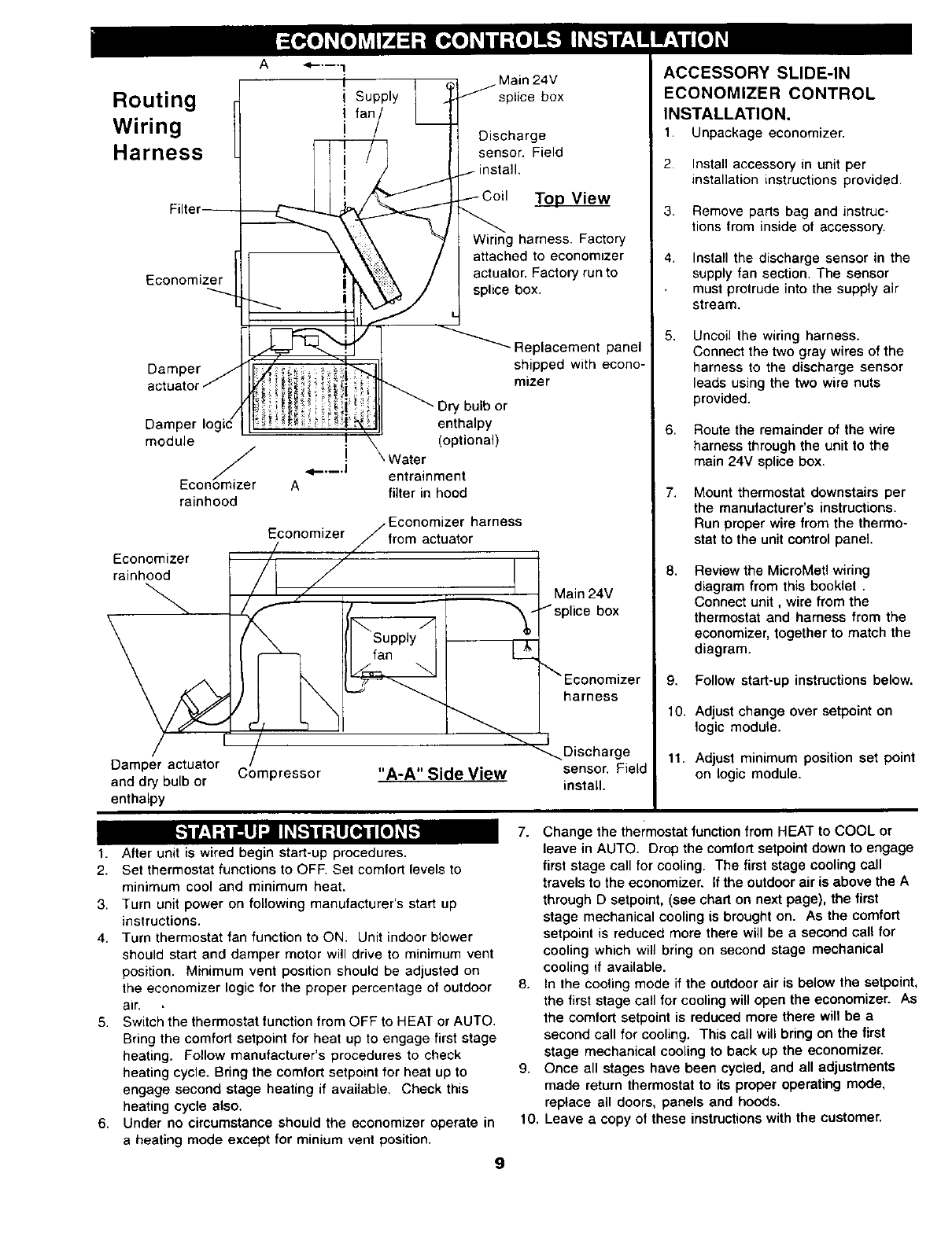
Routing
Wiring
Harness
A _'-'--'3
Economizer
Damper
Supply
fan/
or
Dart enthalpy
module (optional)
iWater
"q--'--'J entrainment
EconOmizer A filter in hood
rainhood
Economizer harness
Economizer actuator
Economizer
rainhoed
Damper actuator
and dry bulb or Compressor
enthalpy
Main 24V
splice box
Discharge
sensor. Field
To.._op_View
Wiring harness. Factory
attached to economnzer
actuator. Factory run to
splice box.
Replacement panel
shipped with econo-
mizer
Main 24V
=lice box
harness
"A-A"SideView
Discharge
sensor. Field
install.
ACCESSORY SLIDE-IN
ECONOMIZER CONTROL
INSTALLATION,
1. Unpackage economizer,
2. Install accessory in unit per
installation instructions provided.
3. Remove parts bag and instruc-
tions from inside of accessory.
4, Install the discharge sensor in the
supply fan section. The sensor
must protrude into the supply air
stream.
5, Uncoil the wiring harness.
Connect the two gray wires of the
harness to the discharge sensor
leads using the two wire nuts
provided.
6. Route the remainder of the wire
harness through the unit to the
main 24V splice box.
7. Mount thermostat downstairs per
the manufacturer's instructions.
Run proper wire from the thermo-
stat to the unit control panel.
8,
9,
10.
11.
Review the MicroMetl wiring
diagram from this booklet.
Connect unit, wire from the
thermostat and harness from the
economizer, together to match the
diagram.
Follow start-up instructions below.
Adjust change over setpoint on
logic module.
Adjust minimum position set point
on logic module.
d[.:']
1. After unit is wired begin start-up procedures.
2. Set thermostat functions to OFF. Set comfort levels to
minimum cool and minimum heat.
3. Turn unit power on following manufacturer's start up
instructions.
4. Turn thermostat fan function to ON. Unit indoor blower
should start and damper motor will drive to minimum vent
position. Minimum vent position should be adjusted on
the economizer logic for the proper percentage of outdoor
air. *
5. Switch the thermostat function from OFF to HEAT or AUTO.
Bring the comfort setpoint for heat up to engage first stage
heating. Follow manufacturer's procedures to check
heating cycle. Bring the comfort setpoint for heat up to
engage second stage heating if available. Check this
heating cycle also.
6. Under no circumstance should the economizer operate in
a heating mode except for minium vent position.
g
7. Change the thermostat function from HEAT to COOL or
leave in AUTO. Drop the comfort setpoint down to engage
first stage call for cooling. The first stage cooling call
travels to the economizer. If the outdoor air is above the A
through D setpoint, (see chart on next page), the first
stage mechanical cooling is brought on. As the comfort
setpoint is reduced more there will be a second call for
cooling which will bring on second stage mechanical
cooling if available.
8. In the cooling mode if the outdoor air is below the satpoint,
the first stage call for cooling will open the economizer. As
the comfort setpoint is reduced more there will be a
second call for cooling. This call will bdng on the first
stage mechanical cooling to back up the economizer.
9. Once all stages have been cycled, and all adjustments
made return thermostat to its proper operating mode,
replace all doors, panels and hoods.
10. Leave a copy of these instructions with the customer.

These instructions are for fully modulating elec-
tronically controlled economizers utilizing solid
state logic throughout. A standard single or
(recommended) two stage thermostat is all that is
needed to complete the control and economizer
system for the HVAC equipment.
1.
2.
3.
4.
5.
Damper actuator .., 9901-0083 provides 24v modulating
control of economizer dampers, 25 in. lb. of torque.
(Honeywell M7415A-1006)
Ball joint for linkage connection.
Discharge sensor ... 9901-0001 provides a signal (3000
Ohms at 25°C or 77°F) to the actuator during free cooling
or economizer mode. The signal opens the economizer
damper until the discharge temperature drops below 55 °.
At this time the signal causes the motor to modulate the
damper and mix outside air with return air to maintain a
50° R to 56 ° R discharge temperature.
Wire nuts to connect discharge sensor to the harness.
Economizer logic ... 9901-0017 accepts input from
discharge _ensor and outside air sensor. Analyzes input
to control actuator modulation and economizer switching.
Logic also houses minimum position adjustment and
enthalpy or adjustable dry bulb adjustment. When used
with optional differential sensors in the return air, the logic
is capable of selecting the most economical air available
for cooling. (Honeywell W7459A-1001)
6. Dry bulb...9901-0183 senses temperature of outside air
and provides signal to the economizer logic. Opens
outside air at 60 °, closes outside air at 70 ° (enthalpy
optional).
7. 5/8" grommet fits 5/8" hole that wires may pass through to
keep from chaffing.
8. Wire clamps to secure wires to base, dividers, etc..
9. Wire harness color coded and pre-wired to actuator and
economizer logic... 9962-0087.
10. 1/2" hex head screws to secure wire clamps.
10
The purpose of an economizer is to use outdoor air
for cooling, whenever possible, to reduce compres-
sor operation.
The economizer system initially responds to a signal
from the cooling thermostat and functions as a true
first stage for cooling, while providing maximum fuel
economy. The economizer is automatically locked
out during the heating mode and holds the outdoor
air damper at the minimum position settings.
During the occupied period, on a call for cooling,
when outdoor air temperature or enthalpy (optional)
conditions are low, the economizer actuator will
proportion to maintain between 50 °-F and 56-oF at
thermistor discharge sensor.
If the mixed or discharge temperature is above 56°- F,
actuator will open to admit additional outdoor air until
the temperature returns to the 50 °-to 56-° F range. If
the mixed or discharge air temperature is below 50_
F, the actuator will proportion closed, shutting the
outdoor air damper until the temperature returns to
the 50 -oto 56-oF range. During the occupied period,
the actuator will not close past the minimum
position.
If the fully open actuator cannot satisfy the space
demand, mechanical cooling is sequenced on.
During the unoccupied period, the actuator will
override minimum position setting and drive fully
closed. On a loss of power, the actuator will spring
return fully closed.
When in heating operation, or when outdoor air
temperature or enthalpy (optional) conditions are
high, economizer operation is locked out, and
actuator is held at minimum position.
The staging relay is used when the first stage
compressors must provide mechanical cooling
when assisting the economizer.
The staging relay can be omitted when the second
stage compressors can be used to assist the
economizer with mechanical cooling.
tt
Lvli_ It it It, iI "..-V_L='_((*},Ir "__';i_71_Jf,, [_, [
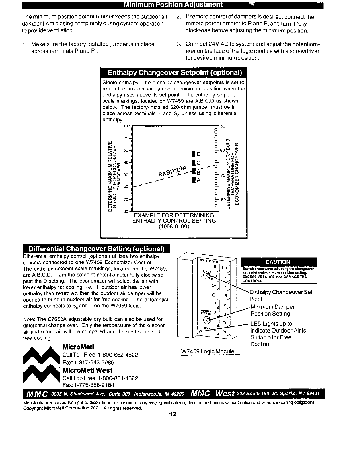
The minimum position potentiometer keeps the outdoor air 2. If remote control of dampers is desired, connect the
damper from closing completely during system operation remote potentiometer to P and P and turn it fully
to provide ventilation, clockwise before adjusting the minimum position.
1. Make sure the factory installed jumper is in place
across terminals P and P_.
3. Connect 24V AC to system and adjust the potentiom-
eter on the face of the logic module with a screwdriver
for desired minimum position.
Single enthalpy: The enthalpy changeover setpoints is set to
return the outdoor air damper to minimum position when the
enthalpy rises above its set point. The enthalpy setpoint
scale markings, located on W7459 are A,B,C,D as shown
below. The factory-installed 620-ohm lumper must be in
place across terminals + and S,_unless using differential
enthalpy.
10
20-
W
---_13£
I-uJ
<;__ d0-
uJ:E
_O 40-
zo:
:_ow
_t)>
__wO 5o-
XQ_O
_ ,,0,< 60-
Q:.q 70-
wI
D 80
lid
IC .
IA
5O
e0 ::..i_ O>
i 0::0 w
aw(.9
T:EwZ
:_,_
::_Wz°
'_-o
-80W (j
'LII _,1
EXAMPLE FOR DETERMINING
ENTHALPY CONTROL SETTING
(1008-0100)
i I]'il I_ _[;]il ir_l I[i.] i_1 i[. [_._,_;] dl.."._[_ i,[. |1_ 'i[.] i f; iii
Differential enthalpy control (optional) utilizes two enthalpy
sensors connected to one W7459 Economizer Control.
The enthalpy setpoint scale markings, located on the W7459,
are A,B,C,D. Turn the setpoint potentiometer fully clockwise
past the D setting. The economizer will select the air with
lower enthalpy for cooling; i.e., if outdoor air has lower
enthalpy than return air, then the outdoor air damper will be
opened to bring in outdoor air for free cooling. The differential
enthalpy connects to S_and + on the W7959 logic.
Note: The C7650A adjustable dry bulb can also be used for
differential change over. Only the temperature of the outdoor
air and return air will be compared and the best selected for
free cooling.
MMlcroMeU
Call Toll-Free: 1-800-662-4822
Fax: 1-317-543-5986
_ icroMetlWest
Call Toll-Free: 1-800-884-4662
Fax: 1-775-356-9184
.% _L''- Enthalpy Changeover Set
Point
._.iMinimum Damper
Position Setting
.._p...--.--LEDLights up to
indicate Outdoor Air is
Suitable for Free
Cooling
W7459 Logic Module
Manufac_rerreservesthe rightto discontinue,or change at anytime, specifications,designsand priceswithoutno'_ceand withoutincurnngobligations.
Copyhght MicroMetl Corporation 2001. All rights reserved. 12
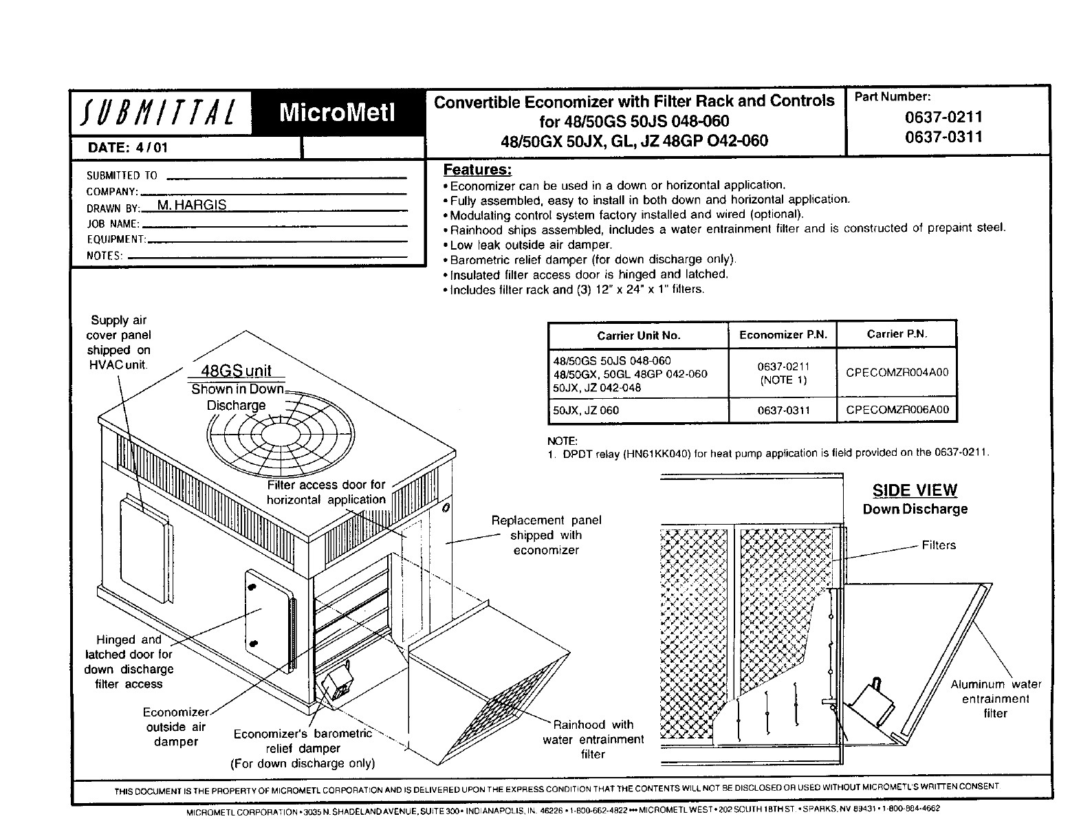
SUBMITTED TO
COMPANY:
DRAWN BY: M. HARGIS
JOB NAME:
EQUIPMENT:
NOTES:
Supply air
cover panel
shipped on
HVAC unit.
Features:
• Economizer can be used in a down or horizontal application.
• Fully assembled, easy to install in both down and horizontal application.
•Modulating control system factory installed and wired (optional).
• Rainhood ships assembled, includes a water entrainment filter and is constructed of prepaint steel.
• Low leak outside air damper.
•Barometric relief damper (for down discharge only).
•Insulated filler access door is hinged and latched.
•Includes filter rack and (3) 12" x 24" x 1"filters.
Carrier Unit No. Economizer P.N. Carrier P,N.
48/50GS 50JS 048-060 0637-0211
48/50GX. 50GL 48GP 042-060 (NOTE 1) CPECOMZR004A00
50JX, JZ 042-048
50JX, JZ 060 0637-0311 CPECOMZR006A00
NOTE:
1. DPDT relay (HN61KK040) for heat pump application is field provided on the 0637-0211.
Replacement panel
shipped with
economizer
SIDE VIEW
Down Discharge
Filters
Hinged
latched door for
down discharge
filter access
"with
outside air Economizer's barometnc "-.... water entrainment
damper relief damper _,. filter
(For down discharge only)
Aluminum water
entrainment
filter
THIS OOCUMENT IS THE PROPERTY OF MICROM ETL CORPORATION AND IS DELIVER ED UPON THE EXPRESS CONDITION THAT THE CONTENTS WILL NOT BE DISCLOSED O R US ED WITHOUT MICROMETL'S WRI_ EN CONSENT
MICROMETLCORPORATION*3035N SHADELANDAVENUE,SUITE300 °INOIANAPOLIS, IN 46226*l-800-662-4822_MICROMETLWES T°202SOUTH 18THS- °SPARKS,NV 89431 ol 800-884-466E

14

15

Ilk 582A-42-1 /48/50-103SI Catalog No. 534-80093 Page 16
