CARRIER Air Handler (indoor Blower&evap) Manual L0210326
User Manual: CARRIER CARRIER Air Handler (indoor blower&evap) Manual CARRIER Air Handler (indoor blower&evap) Owner's Manual, CARRIER Air Handler (indoor blower&evap) installation guides
Open the PDF directly: View PDF ![]() .
.
Page Count: 4
Installation Instructions
Downflow
Conversion Kit
KFADC
NOTE: Read the entire instruction manual before starting the installation.
This symbol --_ indicates a change since the last issue.
SAFETY CONSIDERATIONS
Installing and servicing air conditioning equipment can be hazardous due to system pressures and electrical components. Only trained personnel
should install or service air conditioning equipment.
Untrained personnel can pertbnn basic maintenance functions such as cleaning coils, or cleaning and replacing filters. All other operations should
be performed by trained service personnel. When working on air conditioning equipment, observe precautions in the literature, and on tags and
labels attached to the unit.
Follow all salary codes. Wear safety glasses and work gloves. Use a quenching cloth lor brazing operations. Have a fire extinguisher available.
Recognize safety information. This is the sal_ty-alert symbolz_. When you see this symbol on the unit and instructions or manuals, be alert to
the potential for personal injury.
Understand the signal words DANGER, WARNING, and CAUTION. These words are used with the safety-alert symbol. DANGER identifies the
most serious hazards which will result in severe personal injury or death. WARNING signifies hazards which could result in personal injury or
death. CAUTION is used to identify unsafe practices which would result in minor personal injury or product and property damage.
WARNING: Before beginning any installation or modification, be sure the main electrical disconnect switch is in the
OFF position. Tag the disconnect switch with a suitable warning label. Electrical shock can cause personal injury or death.
INTRODUCTION
Fan coils are factory-shipped tor up flow or horizontal-left applications. This instruction covers the installation of downflow conversion kit on
models FA, FB, FC, FK, FX, FV, and PF fan coils and FH fan unit. The kit provides a means of installing fan coils in a downflow position.
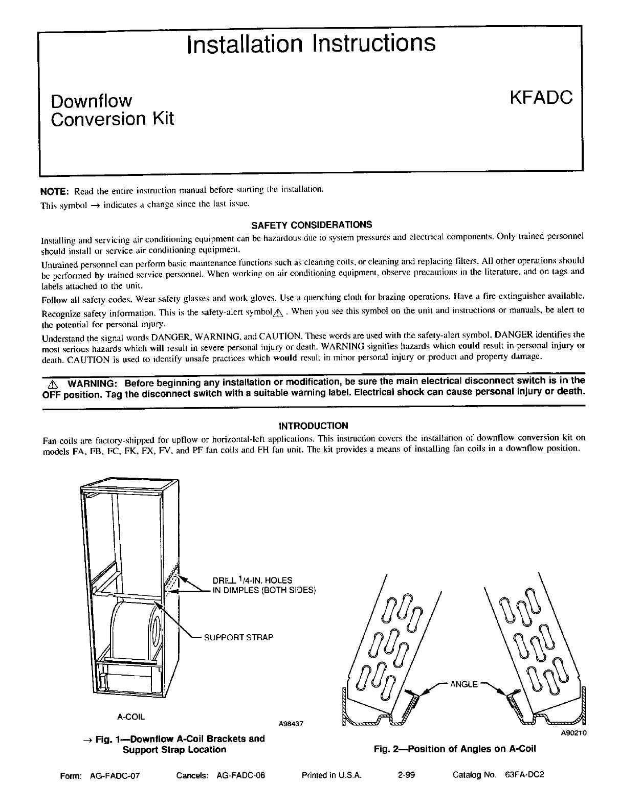
A-COIL
-_ Fig. 1--Downflow A-Coil Brackets and
Support Strap Location
A98437
A90210
Fig. 2--Position of Angles on A-Coil
Form: AG-FADC-07 Cancels: AG-FADC-O6 Printed in U.S.A. 2-99 Catalog No. 63FA-DC2
DESCRIPTIONANDUSAGE
The downllow conversion kits are available for use on slope and A-coil versions of previously mentioned fan coils. When installed, the kit will
provide proper condensate water drainage, as well as a means of supporting the coil. See unit Installation Instructions lor proper kit part numbers.
The downflow conversion 1or slope units requires the lk_llowing items:
Coil bracket ( I )
Coil baffle ( 1!
Screws (21
Foam gasket ( I )
The downflow conversion for A-coil units requires the t_'_liowing items:
Coil bracket I2t
Support strap (It
Drainage hole plugs (21
Angle (2)
Screws (41
Air seal !1)
NOTE: The fan coils are l_ctory shipped l;3r upflow or horizontal-lefl applications. Installation or the Downflow Convcrsion Kit should be
complete before the fan coil unit is positioned to ensure side access required Ik_r installation of the coil brackets.
NOTE: If unit has electric heat with a circuit breaker, rel_r 1o electric heater Installation [nstructions tbr repositioning of breaker assembly.
INSTALLATION---A-COIL UNITS ONLY
1. Remove all panels and expose blower and coil areas.
2. Remove any shipping clips securing coil.
3, Remove complete coil/drain pan assembly.
4. Remove and discard horizontal drain pan from coil assembly.
5. Drill four 1/4-in. holes (2 on each side) in fan coil casing at dimples provided. (See Fig. 1.)
6. Secure coil brackets (provided in kit) to casing sides. (See Fig. l.)
7. Install support strap (provided in kit) across front of unit as follows:
a. Position flange on each end of strap between coil bracket and casing insulation. (See Fig. 1.)
b. Secure support strap ends m coil brackets. (See Fig. 1.)
8. Remove and discard 4 clips (on comers of coil) securing coil assembly to rails for upflow applications.
9. Remove and discard factory-shipped air seal and drain tube assembly. Install l-piece sheet metal air seal assembly provided with kit.
10. Tilt coil assembly back and slide angles (provided in kit) over each inside wall of condensate pan. Pop-riveted flange of angles should extend
toward coil. (See Fig. 2.)
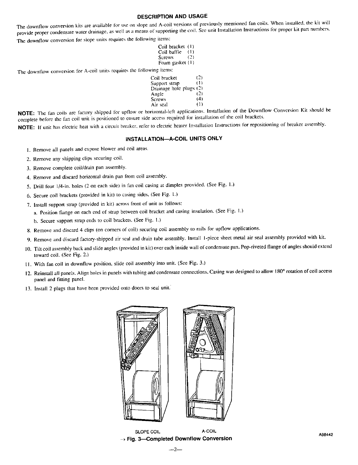
11. With fan coil in downflow position, slide coil assembly into unit. (See Fig. 3.)
12. Reinstall all panels. Align holes in panels with tubing and condensate connections. Casing was designed to allow 180° rotation of coil access
panel and fitting panel.
13. Install 2 plugs that have been provided onto doors to seal unit.
SLOPE COIL ACOIL
-3- Fig. 3_Completed Downflow Conversion
--2--
A98442
INSTALLATION--SLOPE COIL UNITS ONLY
I. Remove all panels and expose blower and coil areas.
2. Remove screw securing coil assembly to right side flange. Remove complete coil/drain pan assembly.
3. Drill two I/4-in. holes in right side of casing at dimples provided (unit in upflow position).
4. Place fan coil unit in downt]ow position.
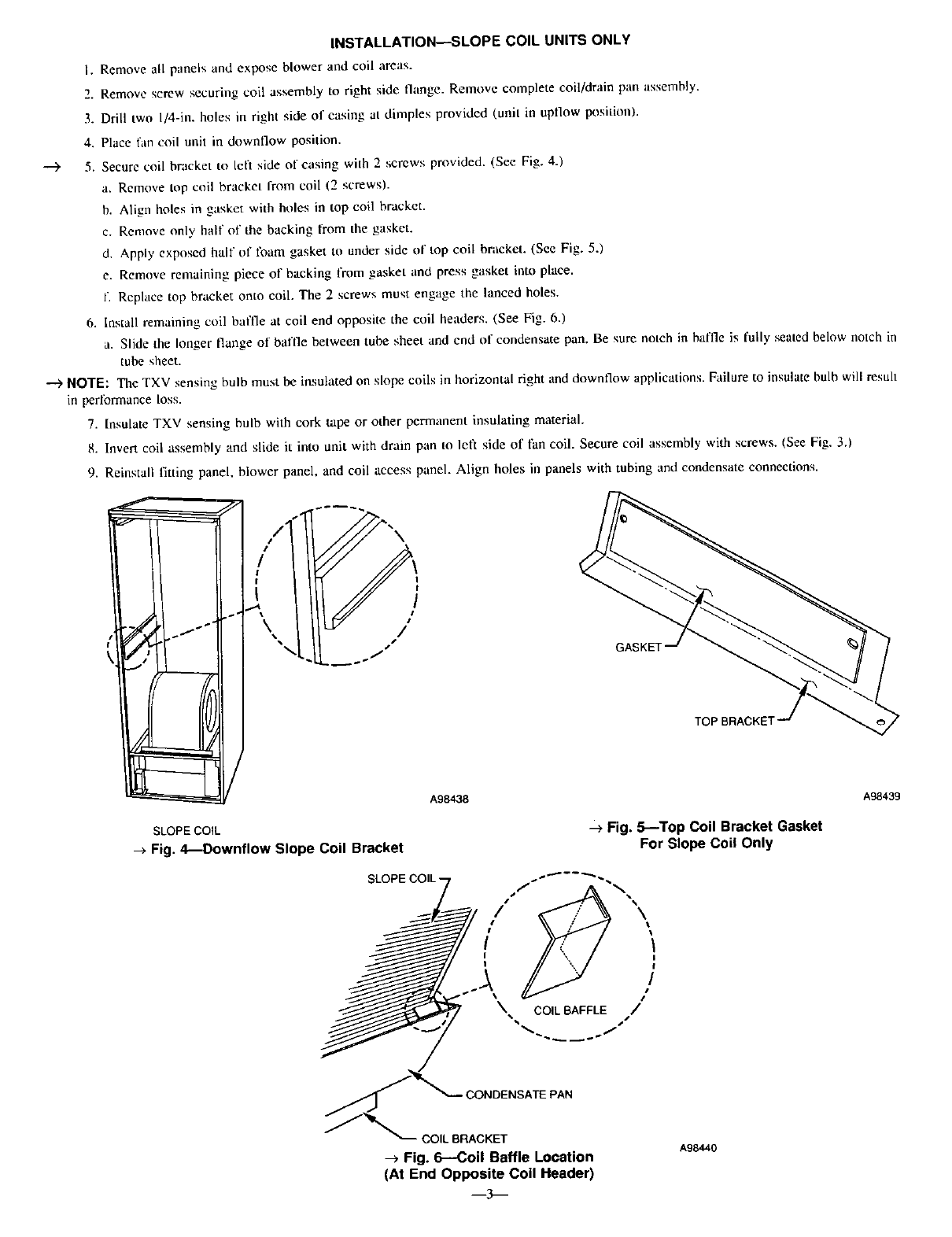
---)' 5. Secure coil bracket to left side of casing with 2 screws provided. (See Fig. 4.)
a. Remove top coil bracket Irom coil (2 screws).
b. Align holes in gasket with holes in top coil bracket.
c. Remove only half of the backing from the gasket.
d. Apply exposed half of Ioam gasket to under side of top coil bracket. (See Fig. 5.)
e. Remove remaining piece of backing from gasket and press gasket into place.
f. Replace top bracket onto coil. The 2 screws must engage the lanced boles.
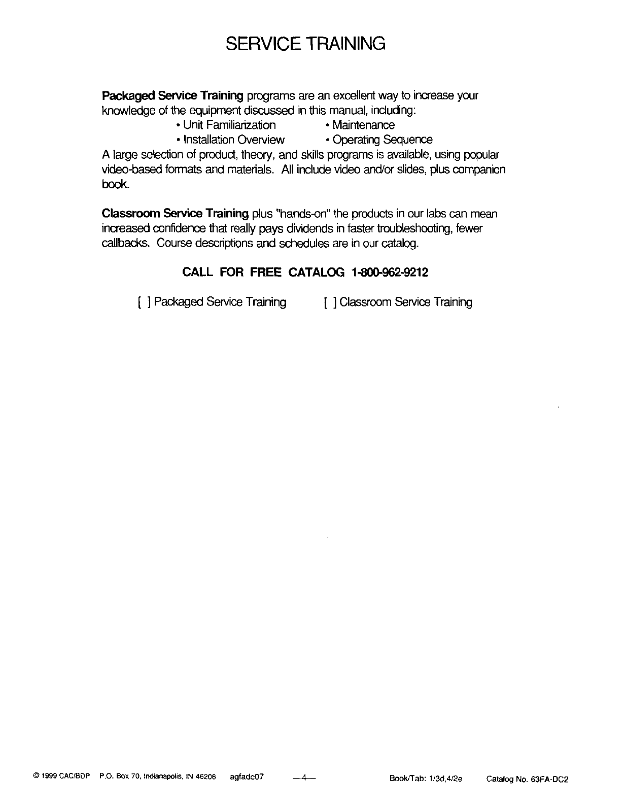
6. Install remaining coil baft'/e at coil end opposite the coil headers. (See/:Zig. 6,)
a. Slide the longer flange of baffle between tube sheet and end of condensate pan. Be sure notch in baffle is fully seated below notch in
tube sheet.
NOTE: The TXV sensing bulb must be insulated on slope coils in horizontal right and downflow applications. Failure to insulate bulb will resu]l
in perlormance loss.
7. Insulate TXV sensing bulb with cork tape or other permanent insulating material.
8, lnverl coil assembly and slide it into unit with drain pan to left side o£ fan coil, Secure coil assembly with screws. (See Fig. 3.)
9. Reinstall fitting panel, blower panel, and coil access panel. Align holes in panels with tubing and condensate connections.
I
I
/
GASKET
TOP BRACKE1
A98438
SLOPE COIL
-> Fig. 4---Downflow Slope Coil Bracket
SLOPE COIL-
-->Fig. 5--Top Coil Bracket Gasket
For Slope Coil Only
A98439
CONOENSA TE PAN
COILBRACKET
Fig. 6--COil Baffle Location
(At End Opposite Coil Header)
--3--
A98440
SERVICE TRAINING
Packaged Service Training programs are an excellent way to increase your
knowledge of the equipment discussed in this manual, including:
• Unit Familiarization *Maintenance
• Installation Overview • Operating Sequence
A large selection of product, theory, and skills programs is available, using popular
video-based formats and materials. All include video and/or slides, plus companion
book.
Classroom Service Training plus "hands-on" the products in our labs can mean
increased confidence that really pays dividends in faster troubleshooting, fewer
callbacks. Course descriptions and schedules are in our catalog.
CALL FOR FREE CATALOG 1-800-962-9212
[ ] Packaged Service Training [ ] Classroom Service Training
© 1999 CAC/SDP P.O. Box 70, Indianapolis, IN 46206 agfadc07 _ Book/Tab: 1/3d,4/2e Catalog No. 63FA-DC2
