CARRIER Ventilator Manual L0211027
User Manual: CARRIER CARRIER Ventilator Manual CARRIER Ventilator Owner's Manual, CARRIER Ventilator installation guides
Open the PDF directly: View PDF ![]() .
.
Page Count: 24
HEATING & COOLING
HRVCCLHU, HRVCCSVU, HRVCCLVU
Heat Recovery
Ventilator
Visil www.camer.com
Installation, Start-Up, and Operating Instructions
Sizes 1150, 1200, 1250, and 1330
NOTE: Read the entire instruction manual before starting the
installation.
Index Page
SAFETY CONSIDERATIONS ..................................................... 2
INTRODUCTION .......................................................................... 2
LOCATION .................................................................................... 2
Inspect Equipment .................................................................... 2
Select Location .......................................................................... 2
UNIT INSTALLATION ............................................................. 2-3
Mount Unit ................................................................................ 2
Independent System Application .............................................. 2
Forced-Air Application ............................................................. 3
Connect Ducts to HRV ............................................................. 3
Condensate Drain ...................................................................... 3
Locate and Install Exterior Hoods ........................................ 3-4
COMPONENT DESCRIPTION .................................................... 5
WALL CONTROL ..................................................................... 4-6
Location ................................................................................. 6-7
Basic Control Operation ........................................................... 6
Standard Control Operation ...................................................... 6
Automatic Control Operation ................................................... 6
Wiring ........................................................................................ 7
Humidity Selector ..................................................................... 7
ELECTRICAL CONNECTIONS ............................................... 7-8
115-vac Wiring ......................................................................... 7
12-vdc Wiring ........................................................................... 8
ACCESSORIES .......................................................................... 8-9
Interlock Relay .......................................................................... 8
20 Minute Timer ....................................................................... 8
60 Minute Adjustable Timer .................................................... 8
BALANCING HRV ................................................................ lO-I 1
Balancing Dampers ................................................................. 10
Flow Collars ...................................................................... 10-11
VENTILATION EVALUATION ........................................... 12-13
Method i................................................................................. 13
Method 2 ................................................................................. 13
CONTROL BOARD OPERATION ............................................ 13
Board Function ........................................................................ 13
Defrost ..................................................................................... 13
Off and Intermittent/Off Mode ............................................... 13
High-Speed Air Exchange ...................................................... 13
Low-Speed Air Exchange ....................................................... 13
CARE AND MAINTENANCE .............................................. 13-14
Door ......................................................................................... 13
Filter ........................................................................................ 14
Blower Motor and Wheel ....................................................... 14
Cleaning'the Core ................................................................... 14
TROUBLESHOOTING .......................................................... 14-17
Wall Control ............................................................................ 14
Control Board .......................................................................... 14
Blower Motor .......................................................................... 14
Blower Speed Selection .......................................................... 14
Defrost ................................................................................ 14-16
Control Module Jumpers ........................................................ 16
Error Signaling .................................................................. 16-17
WIRING DIAGRAMS ........................................................... 18-19
DIMENSIONAL DRAWINGS .............................................. 20-22
A99271
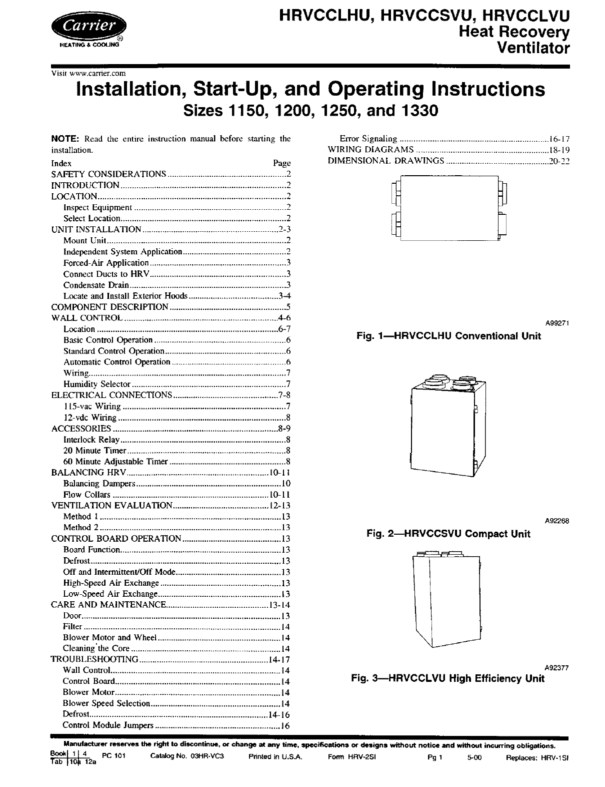
Fig. 1--HRVCCLHU Conventional Unit
A92268
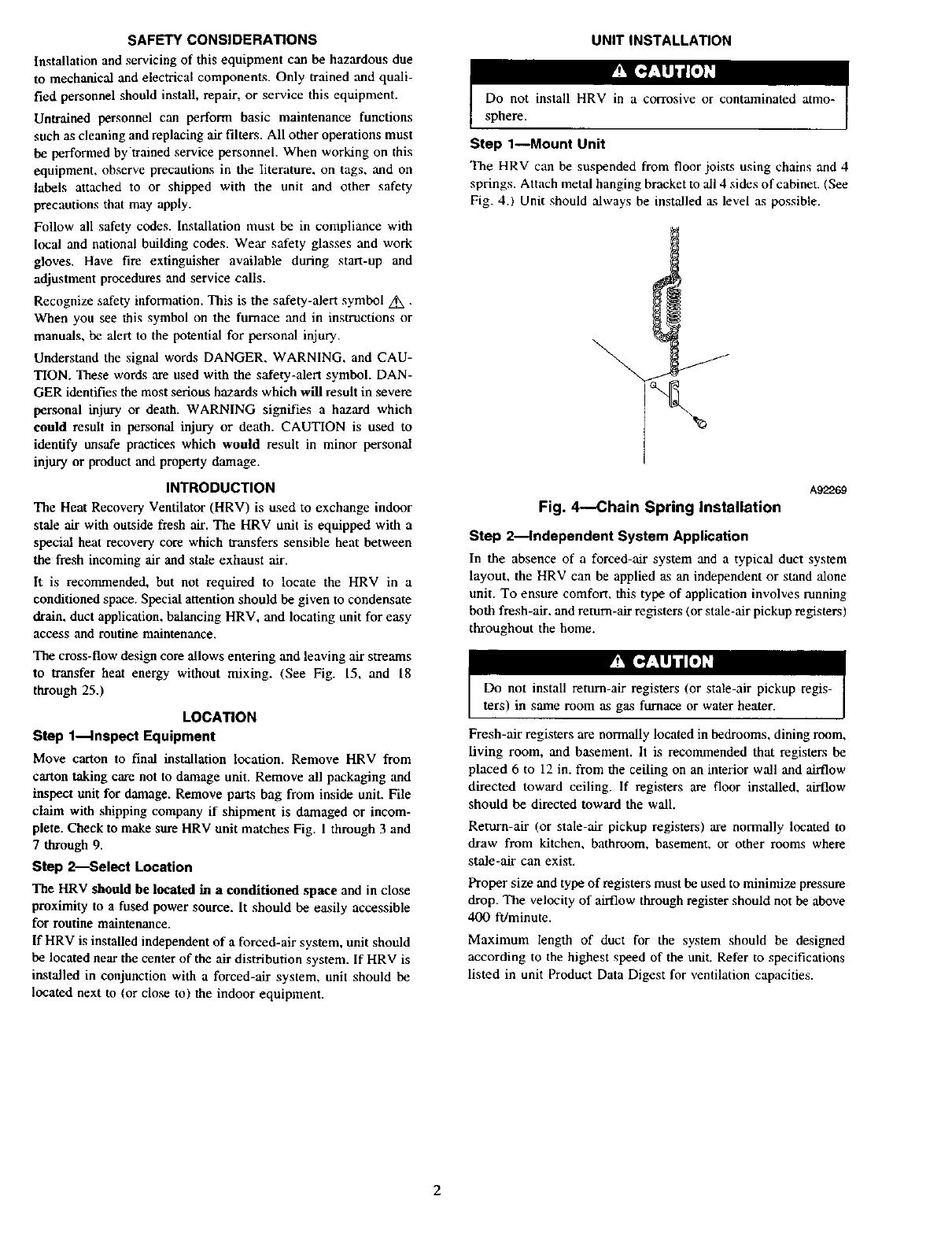
Fig. 2--HRVCCSVU Compact Unit
\j
A92377
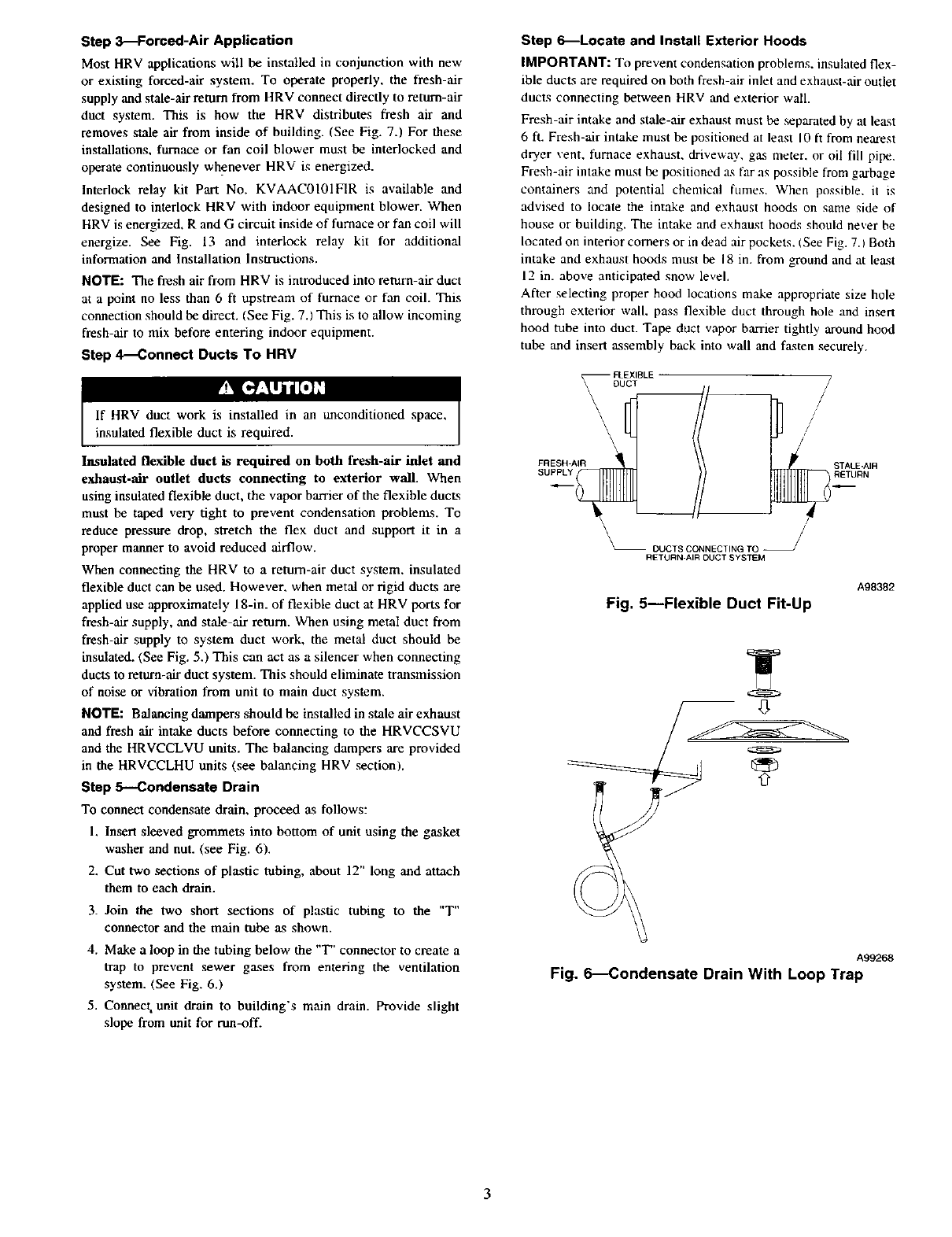
Fig. 3_HRVCCLVU High Efficiency Unit
Manufacturer reserves the right to discontinue, or change at any time, specifications or designs without notice and without incurring obligations.
_2 PC 101 Catalog NO. 03HR-VC3 Printed in U.S.A. Form HRV-2SI Pg 1 5-00 Replaces: HRV-1SI
a
SAFETY CONSIDERATIONS
Installation and servicing of this equipment can be hazardous due
to mechanical and electrical components. Only trained and quali-
fied personnel should install, repair, or service this equipment.
Untrained personnel can perform basic maintenance functions
such as cleaning and replacing air filters. All other operations must
be performed bytrained service personnel. When working on this
equipment, observe precautions in the literature, on tags, and on
labels attached to or shipped with the unit and other safety
precautions that may apply.
Follow all safety codes. Installation must be in compliance with
local and national building codes. Wear safety glasses and work
gloves. Have fire extinguisher available during start-up and
adjustment procedures and service calls.
Recognize safety information. This is the safety-alert symbol Z_x•
When you see this symbol on the furnace and in instructions or
manuals, be alert to the potential for personal injury.
Understand the signal words DANGER, WARNING, and CAU-
TION. These words are used with the safety-alert symbol. DAN-
GER identifies the most serious hazards which will result in severe
personal injury or death. WARNING signifies a hazard which
could result in personal injury or death. CAUTION is used to
identify unsafe practices which would result in minor personal
injury or product and property damage.
INTRODUCTION
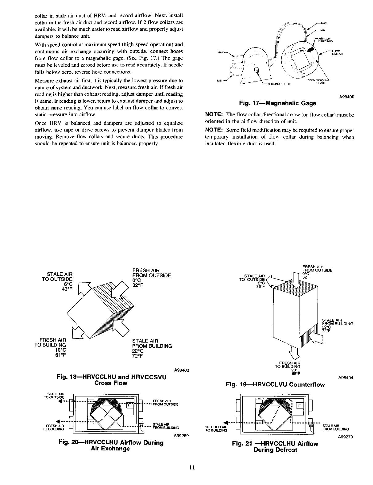
The Heat Recovery Ventilator (HRV) is used to exchange indoor
stale air with outside fresh air. The HRV unit is equipped with a
special heat recovery core which transfers sensible heat between
the fresh incoming air and stale exhaust air.
It is recommended, but not required to locate the HRV in a
conditioned space. Special attention should be given to condensate
drain, duct application, balancing HRV, and locating unit for easy
access and routine maintenance.
The cross-flow design core allows entering and leaving Mr streams
to transfer heat energy without mixing. (See Fig. 15, and 18
through 25.)
LOCATION
Step l_lnspect Equipment
Move carton to final installation location. Remove HRV from
carton taking care not to damage unit. Remove all packaging and
inspect unit for damage. Remove parts bag from inside unit. File
claim with shipping company if shipment is damaged or incom-
plete. Check to make sure HRV unit matches Fig. 1 through 3 and
7through 9.
Step 2-_Select Location
The HRV should be located in a conditioned space and in close
proximity to a fused power source. It should be easily accessible
for routine maintenance.
If HRV is installed independent of a forcod-air system, unit should
be located near the center of the air distribution system. If HRV is
installed in conjunction with a forced-air system, unit should be
located next to (or close to) the indoor equipment.
UNIT INSTALLATION
Do not install HRV in a corrosive or contaminated atmo-
sphere.
Step 1--Mount Unit
The HRV can be suspended from floor joists using chains and 4
springs. Attach metal hanging bracket to all 4 sides of cabinet. (See
Fig. 4.1 Unit should always be installed as level ,as possible.
A92269
Fig. 4---Chain Spring Installation
Step 2_lndependent System Application
In the absence of a forced-Mr system and a typical duct system
layout, the HRV can be applied as an independent or stand alone
unit. To ensure comfort, this type of application involves running
both fresh-air, and remm-air registers (or stale-Mr pickup registers)
throughout the home.
Fresh-Mr registers are normally located in bedrooms, dining room,
living room, and basement. It is recommended that registers be
placed 6 to 12 in. from the ceiling on an interior wall and airflow
directed toward ceiling. If registers are floor installed, airflow
should be directed toward the wail.
Retxu_-air (or stale-Mr pickup registers) are normally located to
draw from kitchen, bathroom, basement, or other rooms where
stale-Mr can exist.
Proper size and type of registers must be used to minimize pressure
drop. The velocity of airflow through register should not be above
400 ft/minute.
Maximum length of duct for the system should be designed
according to the highest speed of the unit. Refer to specifications
listed in unit Product Data Digest for ventilation capacities.
2
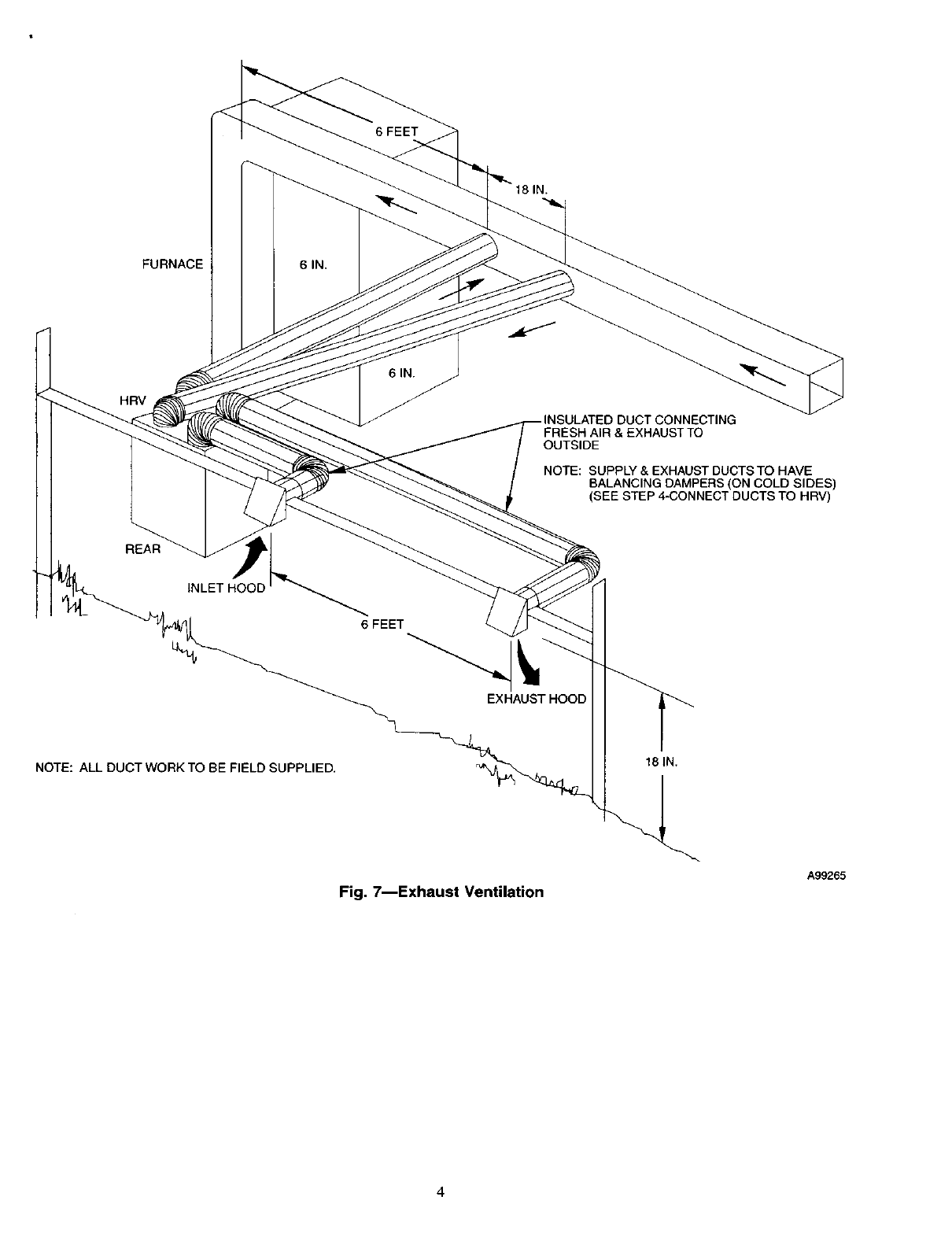
Step 3--Forced-Air Application
Most HRV applications will be installed in conjunction with new
or existing forced-air system. To operate properly, the fresh-air
supply and stale-air return from HRV connect directly to return-air
duct system. This is how the HRV distributes fresh air and
removes stale air from inside of building. (See Fig. 7.) For these
installations, furnace or fan coil blower must be interlocked and
operate continuously whenever HRV is energized.
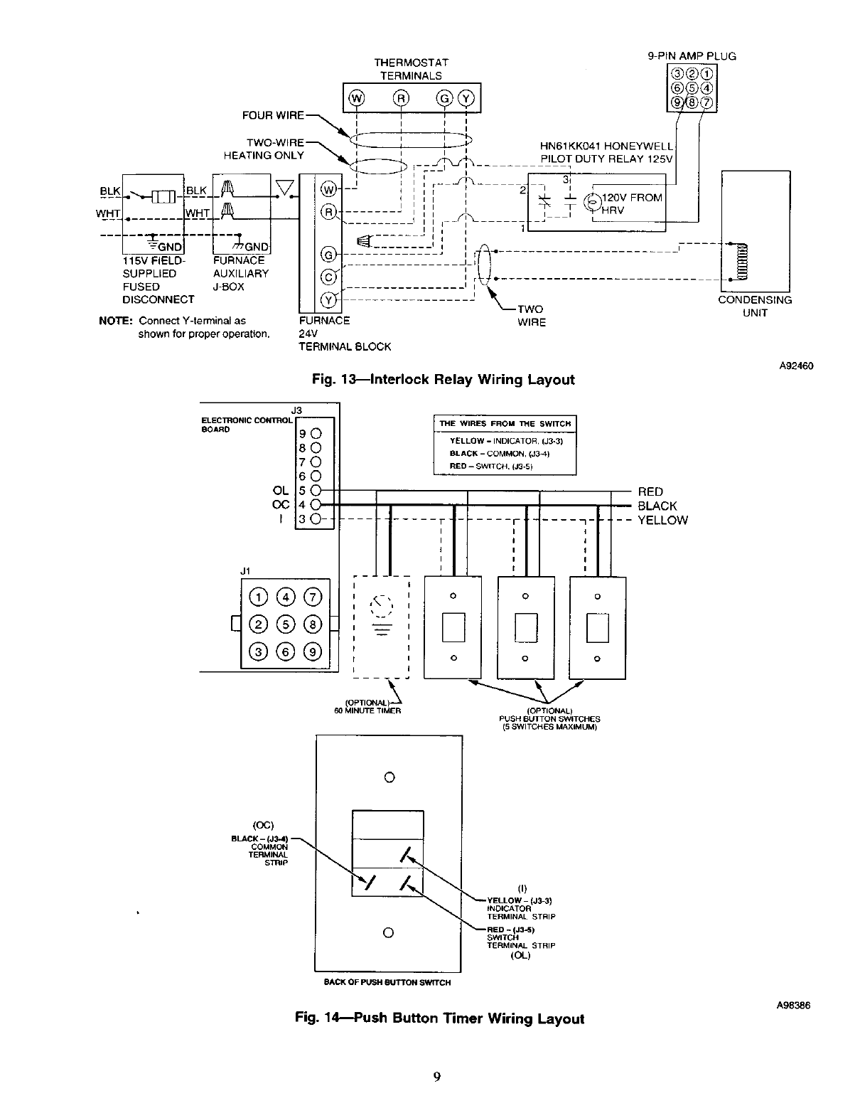
Interlock relay kit Part No. KVAACOI01F1R is available and
designed to interlock HRV with indoor equipment blower. When
HRV is energized. R and G circuit inside of furnace or fan coil will
energize. See Fig. 13 and interlock relay kit for additional
information and Installation Instructions.
NOTE: The fresh air from HRV is introduced into return-air duct
at a point no less than 6 ft upstream of furnace or fan coil. This
connection should be direct. (See Fig. 7.) This is to allow incoming
fresh-air to mix before entering indoor equipment.
Step 4JConnect Ducts To HRV
Insulated flexible duct is required on both fresh-air inlet and
exhaust-alr outlet ducts connecting to exterior wail. When
using insulated flexible duct, the vapor barrier of the flexible ducLs
must be taped very tight to prevent condensation problems. To
reduce pressure drop, stretch the flex duct and support it in a
proper manner to avoid reduced airflow.
When connecting the HRV to a return-air duct system, insulated
flexible duct can be used. However, when metal or rigid ducts are
applied use approximately 18-in. of flexible duct at HRV ports for
fresh-air supply, and stale=air return. When using metal duct from
fresh-air supply to system duct work, the metal duct should be
insulated. (See Fig. 5.) This can act as a silencer when cormecting
ducts to return-air duct system. This should eliminate transmission
of noise or vibration from unit to main duct system.
NOTE: Balancing dampers should be installed in stale air exhaust
and fresh air intake ducts before connecting to the HRVCCSVU
and the HRVCCLVU units. The balancing dampers are provided
in the HRVCCLHU units (see balancing HRV section).
Step 5--Condensate Drain
To connect condensate drain, proceed as follows:
1. Insert sleeved grommets into bottom of unit using the gasket
washer and nut. (see Fig. 6).
2. Cut two sections of plastic tubing, about 12" long and attach
them to each drain.
3. Join the two short sections of play, tic tubing to the "T"
connector and the main tube as shown.
4. Make a loop in the tubing below the "T" connector to create a
trap to prevent sewer g;xses from entering the ventilation
system. (See Fig. 6.1
5. Connect unit drain to building's main drain. Provide slight
slope from unit for run-off.
Step 6_Locate and Install Exterior Hoods
IMPORTANT: To prevent condensation problems, insulated flex-
ible ducts are required on both fresh air inlet and exhaust-air outlet
ducts connecting between HRV and exterior wail.
Fresh air intake and stale-air exhaust must be separated by at least
6 ft. Fresh-air intake must be positioned at least 10 ft from nearest
dryer _ent, furnace exhaust, driveway, g_s meter, or oil fill pipe.
Fresh-air intake must be positioned as far as possible from garbage
containers and potential chemical fumes. When possible, it is
advised to locate the intake and exhaust hoods on same side of
house or building. The intake and exhaust hoods should never be
located on interior corners or in dead air pockets. (See Fig. 7. )Both
intake and exhaust hoods must be 18 in. from ground and at lea,st
12 in. above anticipated snow level.
After selecting proper hood locations make appropriate size hole
through exterior wall. pass flexible duct through hole and insert
hood tube into duct. Tape duct vapor barrier tightly around hood
tube and insert assembly back into wall and fasten securely.
FLEXIBLE
\ DUCT I
//
STALE-AIR
RETURN
\_ DUCTS CONNECTING TO
RETURN-AIR DUCT SYSTEM
Fig. 5--Flexible Duct Fit-Up
A98382
A99268
Fig. _---_ondensate Drain With Loop Trap
3
6 FEET
FURNACE
HRV
6IN.
6IN.
DUCT CONNECTING
FRESH AIR & EXHAUST TO
OUTSIDE
NOTE: SUPPLY & EXHAUST DUCTSTO HAVE
BALANCING DAMPERS (ON COLD SIDES)
(SEE STEP 4-CONNECT DUCTS TO HRV)
REAR
INLET HOOD
6 FEET
EXHAUST HOOD
NOTE: ALL DUCT WORK TO BE FIELD SUPPLIED. 18 IN.
Fig. 7--Exhaust Ventilation
A99265
Cy
A99283
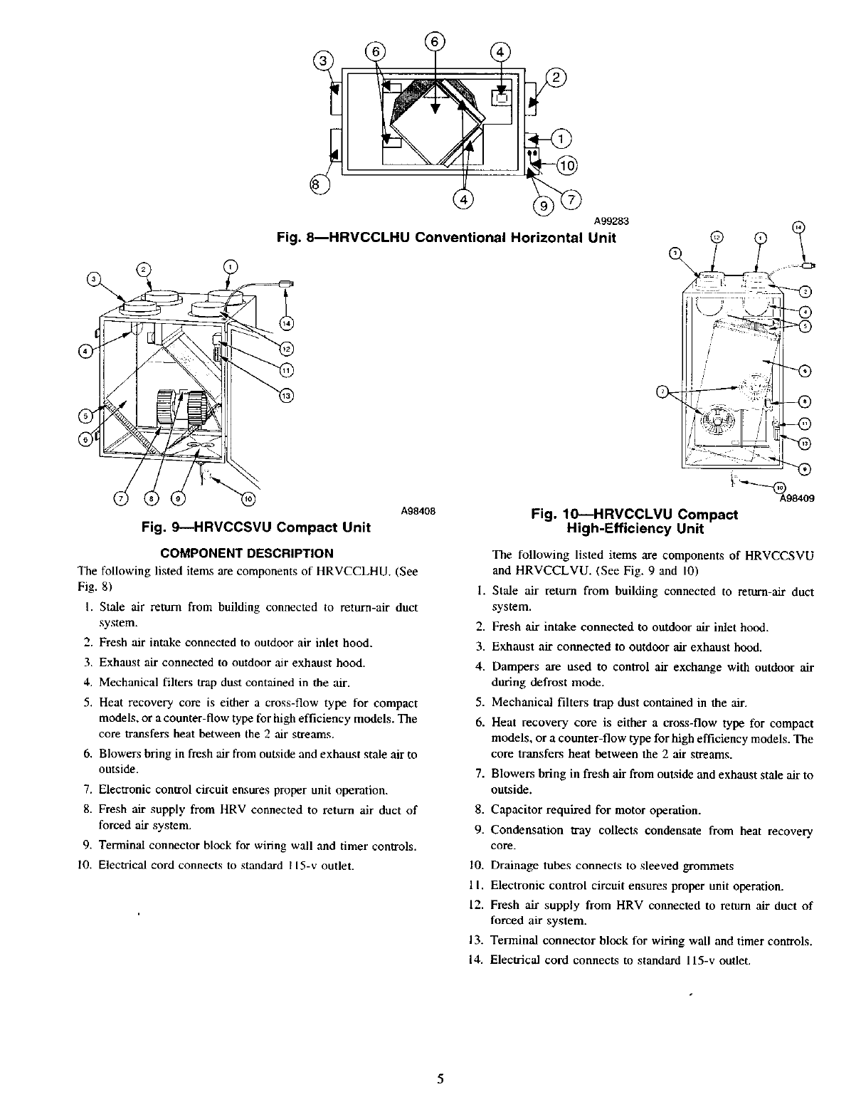
Fig. 8_HRVCCLHU Conventional Horizontal Unit
Fig. 9---HRVCCSVU Compact Unit
A98408 Fig. 10---HRVCCLVU Compact
High-Efficiency Unit
COMPONENT DESCRIPTION
The following listed items are components of HRVCCLHU. (See
Fig. 8)
I. Stale air return from building connected to return-air duct
system.
2. Fresh air intake connected to outdoor air inlet hood.
3. Exhaust air connected to outdoor air exhaust hood.
4. Mechanical filters trap dust contained in the air.
5. Heat recovery core is either a cross-flow type for compact
models+ or a counter-flow type for high efficiency models. The
core transfers heat between the 2 air streams.
6. Blowers bring in fresh air from outside and exhaust stale air to
outside.
7. Electronic control circuit ensures proper unit operation.
8. Fresh air supply from HRV connected to return air duct of
forced air system.
9. Terminal connector block for wiring wall and timer controls.
10. Electrical cord connects to standard I 15-v outlet.
The following listed items are components of HRVCCSVU
and HRVCCLVU. (See Fig. 9 and 10)
I. Stale air return from building connected to return-air duct
system.
2. Fresh air intake connected to outdoor air inlet hood.
3. Exhaust air connected to outdoor air exhaust hood.
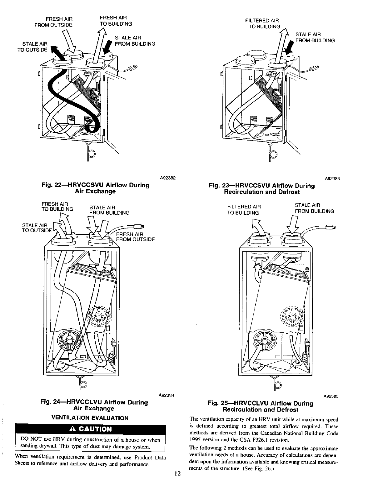
4. Dampers are used to control air exchange with outdoor air
during defrost mode.
5. Mechanical filters trap dust contained in the air.
6. Heat recovery core is either a cross-flow type for compact
models, or a counter-flow type for high efficiency models. The
core transfe_ heat between the 2 air streams.
7. Blowers bring in fresh air from outside and exhaust stale air to
ouLside.
8. Capacitor required for motor operation.
9. Condensation tray collects condensate from heat recovery
core.
I0. Drainage tubes connects to sleeved grommets
1I. Electronic control circuit ensures proper unit operation.
12. Fresh air supply from HRV connected to return air duct of
forced air system.
13. Terminal connector block for wiring wall and timer controls.
14. Electrical cord connects to standard 115-v outlet.
WALL CONTROL
Step 1---Location
The HRV wall controls are unique to HRV and must be installed
for proper unit operation.
Three wall control options are available:
I. Basic Control
2. Standard Control
3. Automatic Control
Step 2IBasic Control Operation
The b_sic control contains a 3 position slide switch which is used
to manually select OFF, LOW. and HIGH speed blower operation.
The unit operates continuously when LOW or HIGH is selected.
tSee Table 1.)
Step 3iStandard Control Operation
The standard control contains an adjustable dehumidistat, and a 3
position slide switch which is used to manually select between
OFF. LOW, and INTERMFIq_NT modes. There are 2 LEDs on
the control to indicate operating mode. (See Table 2.) This control
offers 2 modes of operation:
I. With switch off, HRV is inoperative and both LEDs are out.
(See Fig. 14.)
2. With switch on LOW, HRV continuously exchanges air with
outside. If dehumidistat is satisfied, blower will run in low
speed, otherwise, blower will run on high speed. Both LEDs
are illuminated all the time.
3. With switch on INTERMIq'I'ENT, the HRV exchanges air
with outside on high-speed blower, and unit shuts down when
dehumidistat is satisfied. The ON LED is illuminated all the
time, and AIR EXCHANGE LED is illuminated only when
unit is running. This mode is ideal for maintaining proper
humidity, levels when no one is home.
Step 4_Automatic Control Operation
This control contains an adjustable dehumidistat and push button
switch to cycle between 3 modes of operation. There are 5 LEDs
to indicate mode of operation. (See Table 3.)
NOTE: This control is designed to be used primarily with
installations which are independent of a forced air system (models
HRVCCSVU and HRVCCLVU only).
1. Initially the switch is off. All LEDs are off and HRV is
inoperative.
2. First push of mode button puts HRV into intermittent mode.
The HRV operates at high speed when there is a call for
dehumidification. Intermittent and exchange LEDs are illumi-
nated. When dehumidistat is satisfied, HRV shuts down and
exchange LED goes out.
3. Next push of mode button puts system in continuous mode.
Continuous and exchange LEDs remain on. The HRV oper-
ates at high-speed blower during calls for dehumidification
and low speed when dehumidistat is satisfied.
4. Next push of mode button puts system in circulation mode.
HRV operates in high speed at all times. Circulation LED
remains on. When there is a call for dehumidification,
exchange LED is on and HRV exchanges air with outside.
When dehumidistat is satisfied, HRV dampers close which
recirculates indoor air. The exchange LED goes off.
5. The maintenance light illuminates every 3 months to indicate
filter should be cleaned. It is reset by opening the door to the
HRV.
NOTE: The standard and automatic controls sense humidity not
temperature. Either control must be located in an area where it will
continually monitor fresh air circulating within the home. Install
HRV wall control as close as possible to main system thermostat
and follow same guidelines as installing a thermostat, (locate
approximately 5 ft. [60 in.] above floor, mount on an inside
partitioning wall, ete).
6
MODE
Off
Low
MODE
Off
Low
Intermittent
MODE
Off
Intermittent
Continuous
Recirculation
Any
High
Table 1--Basic Control
OPERATION
Off
Air Exchange
With Outside
Air Exchange
With Outside
DAMPER POSITION
Closed TO Outside
Open To Outside
Open TO Outside
FAN SPEED
Off
Low
High
Table 2_tandard Control
DEHUMIDISTAT POSITION
Any
Satisfied
Call for dehumidification
Satisfied
Call for dehumidification
OPERATION
Off
Off
Air exchange with outside
Air exchange with outside
Air Exchange with Outside
DAMPER POSITION
Closed to outside
Open to outside
Open to outside
Closed to outside
Open to outside
FAN SPEED ON AIR EXCHANGE
LED LED
Off Off Off
Low On Off
High On On
Off On Off
High On On
Table 3_Automatic Control
DEHUMIDISTAT POSITION
Any
Satisfied
Call for dehumidification
Satisfied
Call for dehumidification
Satisfied
Call for dehumidification
Any
OPERATION
off
Air exchange with outside
Air exchange with outside
Air exchange with outside
Air exchange with outside
Recirculation
Air exchange with outside
Any
DAMPER POSITION
Closed to Outside
Open to outside
Open to outside
Open to outside
Open to outside
Closed to outside
Open to outside
FAN SPEED
Off
Off
High
Low
High
High
High
Any
INDICATOR
LEDS
OFF
Intermittent ON
Intermittent and Exchange ON
Continuous and Exchange ON
Continuous and Exchange ON
Recirculation ON
Recitculation and Exchange ON
Maintenance (open door)
Table 4--Recommended Humidity Levels
OUTSIDE TEMPERATURE DOUBLE-PANE TRIPLE-PANE
WINDOWS WINDOWS
50 =F10°C 55 percent 65 percent
32 ° F 0 ° C45 percent 55 percent
14 ° F -10 ° C 35 percent 45 percent
-4° F -20 °C30 percent 45 percent
-22 ° F -30 ° C25 percent 35 percent
If the level of humidity falls too low in the winter months while operating in the continuous exchange mode, a humidifier may be integrated into the system. Intermittent
exchange mode may also be selected for short peedds of time to increase the level of humidity.
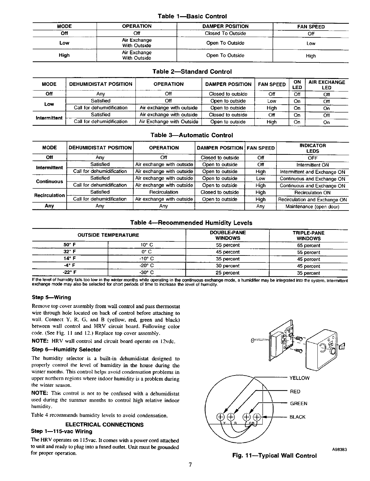
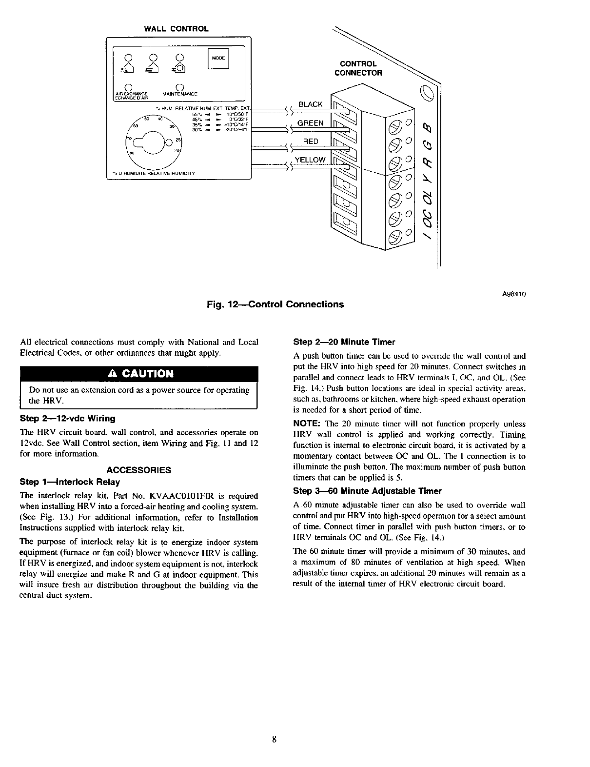
Step 5---Wiring
Remove top cover assembly from wall control and pass thermostat
wire through hole located on back of control before attaching to
wall. Connect Y, R, G, and B (yellow, red, green and black)
between wall control and HRV circuit board. Following color
code. (See Fig. I l and 12.) Replace top cover assembly.
NOTE: HRV wall control and circuit board operate on 12vdc.
Step 6--Humidity Selector
The humidity selector is a built-in dehumidistat designed to
properly control the level of humidity in the house during the
winter months. This control helps avoid condensation problems in
upper northern regions where indoor humidity is a problem during
the winter season.
NOTE: Thks control is not to be confused with a dehumidistat
used during the summer months to control high relative indoor
humidity.
Table 4 recommends humidity levels to avoid condensation.
ELECTRICAL CONNECTIONS
Step 1--115-vac Wiring
The HRV operates on 115vat, It comes with a power cord attached
to unit and ready to plug into a fused outlet. Unit must be grounded
for proper operation.
_..,,=__..__ ELLOW
RED
GREEN
BLACK
A98383
Fig. 11--Typical Wall Control
WALL CONTROL
Iooo ]
o o
CONTROL
Fig. 12---Control Connections
A98410
All electrical connections must comply with National and Local
Electrical Codes, or other ordinances that might apply.
l'y_[R'_lyi[0]_l
Do not use an extension cord as a power source for operating
the HRV.
Step 2--12-vdc Wiring
The HRV circuit board, wall control, and accessories operate on
12vdc. See Wall Control section, item Wiring and Fig. l I and 12
for more information.
ACCESSORIES
Step l_nterlock Relay
The interlock relay kit, Part No. KVAAC0101FIR is required
when installing HRV into a forced-air heating and cooling system.
(See Fig. 13.) For additional information, refer to Installation
Iustructions supplied with interlock relay kit.
The purpose of interlock relay kit is to energize indoor system
equipment (furnace or fan coil) blower whenever HRV is calling.
If HRV is energized, and indoor system equipment is not, interlock
relay will energize and make R and G at indoor equipment. This
will insure fresh air distribution throughout the building via the
central duct system.
Step 2--20 Minute Timer
A push button timer can be used to override the wall control and
put the HRV into high speed for 20 minutes. Connect switches in
parallel and connect leads to HRV terminals 1, OC, and OL. (gee
Fig. 14.) Push button locations are ideal in special activity areas,
such as, bathrooms or kitchen, where high-speed exhaust operation
is needed for a short period of time.
NOTE: The 20 minute timer will not function properly unless
HRV wall control is applied and working correctly. Timing
function is internal to electronic circuit board, it is activated by a
momentary contact between OC and OL. The 1 connection is to
illuminate the push button. The maximum number of push button
timers that can be applied is 5.
Step 3--60 Minute Adjustable Timer
A 60 minute adjustable timer can also be used to override wall
control and put HRV into high-speed operation for a select amount
of time. Connect timer in parallel with push button timers, or to
HRV terminals OC and OL. (See Fig. 14.)
The 60 minute timer will provide a minimum of 30 minutes, and
a maximum of 80 minutes of ventilation at high speed. When
adjustable timer expires, an additional 20 minutes will remain as a
result of the internal timer of HRV electronic circuit board.
8
9-PIN AMP PLUG
THERMOSTAT
TERMINALS
i I
TWO-WIRE__ HN61KK04' HONEYWELLI t
HEATING ONLY i i i PILOT DUTY RELAY 125V
_ _ • vI
i;
Ii......
",----GNO/",--,_GND,, _ ........ '.. =. __ ,:
115VFIELD_ _ I_ .............. .,l,II ..... i
SUPPLIEDAUXILIARYI_ I r_ ....... I
FUSED J-BOX I,1 _.
DISCONNECT I CONDENSING
L__ "LTWO UNIT
NOTE: Connect Y-terminal as FURNACE WIRE
shown for proper operation. 24V
TERMINAL BLOCK
A92460
Fig. 13_lnterlock Relay Wiring Layout
J3
ELECTRONIC CONI_OL --
eO_RO 90
80
70
60
OL ,sO
oc40
i 30--
J1
Q®®
®®®
®®®
:TH E WIRES FROM 33dE SWITCH
YELLOW - INDICATOR `(J3-3)
BLACK - COMMON. (J34}
RED - SWITCH, (J3.5)
.... I_l..... '_ .....
II
II
II
I I
(OPTIONAt._ _
60 MINUTE TIMER
I RED
//BLACK
- __lill-_- -YELLOW
)
[]
)
(OPTIONAL)
PUSH BUTTON SWITCHES
(5 SWITCHES MAXIMUM)
(oc)
BLACK - (J3-4)
COMMON
TERMINAL
S13RIp
©
o
BACK OF PUSH eUTTON SWITCH
__ (i)
YELLOW - (J3-3)
INDICATOR
TERMINAL STRIP
_RED - (J3-5)
SWITCH
TERMINAL STRIP
(OL)
Fig. 1C--Push Button Timer Wiring Layout
A98386
9
BALANCING
DAMPER
STALE AIR
TO OUTSIDe-
f
FRESH AIR SUPPLY _
TO BUILDING _/'
TEMPORARY
_lll i LOW COLLAR
BALANCING
/"DAMPER
FROM OUTSinE
_I_ STALE AIR RETURN
IIII[ \ FROMBU'L°NG
Fig. 15--Balancing HRVCCLHU
FRESHAIR
FROMOUTSIDE
°°F'°W
30"
(760turn)
FRONT-_
STALE AIR
TO OUTSIDE
TEMPORARY
FRESH AIR
FROM OUTSIDE
DAMPER
TEMPORARY
FLOW COLLAR-
FRONT_
2"
(30Omrn)
STALE AIR
TO OUTSIDE
--12"
(300turn)
_B_A_N CIN G
DAMPER
TEMPORARY
-- FLOW COLLAR
A99266
RIGHT SIDE VIEW RIGHT SIDE VIEW
Fig, 16_Balancing HRVCCSVU and HRVCCLVU
A98425
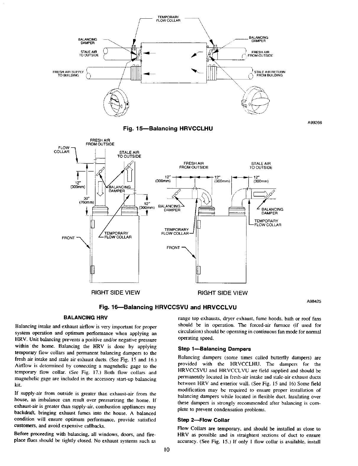
BALANCING HRV
Balancing intake and exhaust airflow is very important for proper
system operation and optimum performance when applying an
HRV. Unit balancing prevents a positive and/or negative pressure
within the home. Balancing the HRV is done by applying
temporary flow collars and permanent balancing dampers to the
fresh air intake and stale air exhaust ducts. (See Fig. 15 and 16.)
Airflow is determined by connecting a magnehelic gage to the
temporary flow collar. (See Fig. 17.) Both flow collars and
magnehelic gage are included in the accessory start-up balancing
kit.
If supply-air from outside is greater than exhaust-air from the
house, an imbalance can result over pressurizing the home. If
exhanst-air is greater than supply-air, combustion appliances may
backdraft, bringing exhaust fumes into the house. Abalanced
condition will ensure optimum performance, provide satisfied
customers, and avoid expensive callbacks.
Before proceeding with balancing, all windows, doors, and fire-
place flues should be tightly closed. No exhaust systems such as
10
range top exhausts, dryer exhaust, fume hoods, bath or roof fans
should be in operation. The forced-air furnace (if used for
circulation) should be operating in continuous fan mode for normal
operating speed.
Step 1--Balancing Dampers
Balancing dampers (some times called butterfly dampers) are
provided with the HRVCCLHU. The dampers for the
HRVCCSVU and HRVCCLVU are field supplied and should be
permanently located in fresh-air intake and stale-air exhaust ducts
between HRV and exterior wall. (See Fig. 15 and 16) Some field
modification may be required to ensure proper installation of
balancing dampers while located in flexible duct. Insulating over
these dampers is strongly recommended after balancing is com-
plete to prevent condensation problems.
Step 2_low Collar
Flow Collars are temporary, and should be installed as close to
HRV as possible and in straightest sections of duct to ensure
accuracy. (See Fig. 15.1 If only Iflow collar is available, install
collar in stale-air duct of HRV, and record airflow. Next, install
coil,u- in the fresh-air duct and record airflow. If 2 flow collars are
available, it will be much easier to read airflow and properly adjust
dampers to balance unit.
With speed control at maximum speed (high-speed operation) and
continuous air exchange occurring with outside, connect hoses
from flow collar to a magnehelic gage. (See Fig. 17.) The gage
must be leveled and zeroed before use to read accurately. If needle
falls below zero, reverse hose connections.
Measure exhaust air first, it is typically the lowest pressure due to
nature of system and ductwork. Next, measure fresh air. If fresh air
reading is higher than exhaust reading, adjust damper until reading
is same. If reading is lower, return to exhaust damper and adjust to
obtain same reading. You can use label on flow collar to convert
static pressure into airflow.
Once HRV is balanced and dampers are adjusted to equalize
airflow, use tape or drive screws to prevent damper blades from
moving. Remove flow collars and secure ducts. This procedure
should be repeated to ensure unit is balanced properly.
A98400
Fig. 17--Magnehelic Gage
NOTE: The flow collar directional arrow !on flow collar1 must be
oriented in the airflow direction of unit.
NOTE: Some field modification may be required to ensure proper
temporary installation of flow collar during balancing when
insulated flexible duct is used.
STALE AIR
TO OUTSIDE
6oc i-_-_ _._-_,/'
FRESH AIR
TO BUILDING
16°C
61°F
FRESH AIR
FROM OUTSIDE
0°C
32°F
>
STALE AIR
FROM BUILDING
22°C
72°F
A98403
Fig. 18---HRVCCLHU and HRVCCSVU
Cross Flow
STALE AIR
TO OUTS_E
,=o. FRESH AIR
•.o.. FROM OUTSIDE
STALE AIR
b""" FROM BUILDING
FRESH AIR
TO BUILDING
A99269
Fig. 20--HRVCCLHU Airflow During
Air Exchange
STALE AIR _
TO OUTSIDE
2oc
36°F
FRESHAIR
TO BUILDING
20°C
68°F
FRESH AIR
FROM OUTSIDE
0oc
32°F
TALE AIR
EROMBUILDLNG
22oc
2OF
Fig. 19---HRVCCLVU Counterflow
A98404
E
" ERE
TO BUILDING
Fig. 21 --HRVCCLHU Airflow
During Defrost
STALE AIR
FROM BUILDING
A99270
11
FRESH AIR FRESH AIR FILTERED AIR
FROM OUTSIDE TO BUILDING TO BUILDING
STALE AIR
TO OUTSIDE
STALE AIR
FROM BUILDING
STALE AIR
BUILDING
Fig. 22_HRVCCSVU Airflow During
Air Exchange
FRESH AIR
TO BUILDING STALE AIR
FROM BUILDING
STALE AIR
FROM OUTSIDE
A92382 A92383
Fig. 23---HRVCCSVU Airflow During
Recirculation and Defrost
FILTERED A_R STALE AIR
TO BUILDING FROM BUILDING
"5
Fig. 24---HRVCCLVU Airflow During
Air Exchange
VENTILATION EVALUATION
A92384
DO NOT use HRV during construction of a house or when
sanding drywall. This type of dust may damage system.
When ventilation requirement is determined, use Product Data
Sheets to reference unit airflow delivery and performance.
12
A92385
Fig. 25--HRVCCLVU Airflow During
Recirculation and Defrost
The ventilation capacity of an HRV unit while at maximum speed
is defined according to greatest total airflow required. These
methods are derived from the Canadian National Building Code
1995 version and the CSA F326.1 revision.
The following 2 methods can be used to evaluate the approximate
ventilation needs of a house. Accuracy of calculations are depen-
dent upon the information available and knowing critical measure-
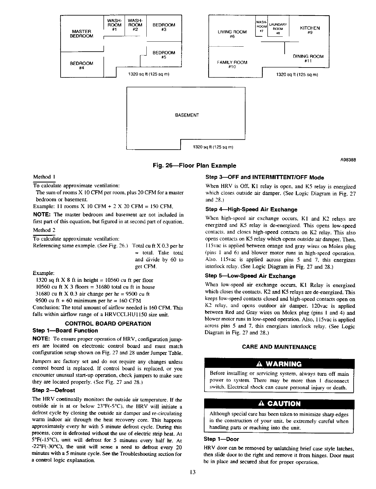
menU; of the structure. (See Fig. 26.)
MASTER
BEDROOM
BEDROOM
#4
WASH-
ROOM
#1
WASH*
BEDROOM
#3
BEDROOM
#5
1320 sq ft (125 sq m)
LIVING ROOM
#6
FAMILY ROOM
#10
W_'_ IJ'UN DARY KITCHEN
IDINING ROOM
#11
I1320 sq ft (125 sq m)
BASEMENT
t320 sq ft (125 sq m)
A98388
Fig. 26_Floor Plan Example
Method 1
To calculate approximate ventilation:
The sum of rooms X 10 CFM per room, plus 20 CFM for a master
bedroom or basement.
Example: 11 rooms X 10 CFM + 2 X 20 CFM = 150 CFM.
NOTE: The master bedroom and basement are not included in
first part of this equation, but figured in at second part of equation.
Method 2
To calculate approximate ventilation:
Referencing same example. (See Fig. 26.) Total cuft X 0.3 per hr
=total. Take total
and divide by 60 to
get CFM.
Example:
1320 st] ft X 8ft in height =10560 cuft per floor
10560 cu ft X 3 floors = 31680 total cuft in house
31680 cuft X 0.3 air change per hr =9500 cuft
9500 cuft +60 minimum per hr = 160 CFM
Conclusion: The total amount of airflow needed is 160 CFM. This
falls within airflow range of a HRVCCLHU1150 size unit.
CONTROL BOARD OPERATION
Step 1--Board Function
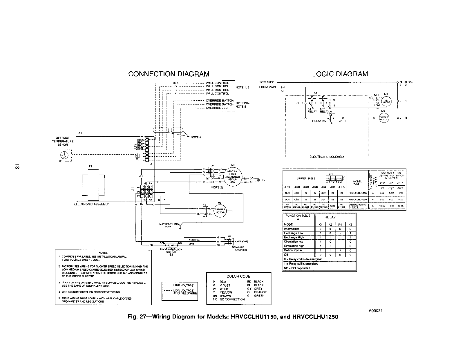
NOTE: To ensure proper operation of HRV, configuration jump-
ers are located on electronic control board and must match
configuration setup shown on Fig. 27 and 28 under Jumper Table.
Jumpers are factory set and do not require any changes unless
control board is replaced. If control board is replaced, or you
encounter unusual start-up operation, check jumpers to make sure
they are located properly. (See Fig. 27 and 28.)
Step 2--Defrost
The HRV continually monitors the outside air temperature. If the
ouLside air is at or below 23°F(-5°C), the HRV will initiate a
defrost cycle by closing the outside air damper and re-circulating
warm indoor air through the heat recovery core. This happens
approximately every hr with 5 minute defrost cycle. During this
process, core is defrosted without the use of electric strip heat. At
5°F(-15°C), unit will defrost for 5 minutes every half hr. At
-22°F(-30°C), the unit will sense a need to defrost every 20
minutes with a 5 minute cycle. See the Troubleshooting section for
a control logic explanation.
Step :)--OFF and INTERMITTENT/OFF Mode
When HRV is Off, KI relay is open, and K5 relay is energized
which closes outside air damper. (See Logic Diagram in Fig. 27
and 28.1
Step 4_High-Speed Air Exchange
When high-speed air exchange occurs, KI and K2 relays are
energized and K5 relay is de-energized. This opens low-speed
contacts, and closes high-speed contacts on K2 relay. This also
opens contacts on K5 relay which opens outside air damper. Then,
115vac is applied between orange and gray wires on Molex plug
(pins 1 and 6) and blower motor runs in high-speed operation.
Also. l l5vac is applied across pins 5 and 7, this energizes
interlock relay. (See Logic Diagram in Fig. 27 and 28.)
Step 5---Low-Speed Air Exchange
When low-speed air exchange occurs, KI Relay is energized
which closes the contacts. K2 and I<5 relays are de-energized. This
keeps low-speed contacts closed and high-speed contacts open on
K2 relay, and opens outdoor air damper. 120vac is applied
between Red and Gray wires on Molex plug (pins 1 and 4) and
blower motor runs in low-speed operation. Also, 115vae is applied
across pins 5 and 7, this energizes interlock relay. (See Logic
Diagram in Fig. 27 and 28.)
CARE AND MAINTENANCE
Step 1--Door
HRV door can be removed by unlatching brief case style latches,
then slide door to the right and remove it from hinges. Door must
be in place and secured shut for proper operation.
13
Step 2--Filter
Filters in HRV are washable and should be cleaned every, 3
months. Use a vacuum cleaner to remove heaviest portion of
accumulated dust, then wash in lukewarm water. Allow filter to
completely dry before reinstalling. Adirty air filter will cause
excessive strain on blower motor. Never operate unit without a
filter. Vacuum out debris.
In addition, regularly check and clean screens on exterior intake
and exhaust hoods when necessary.
V!_[,TLI1Fff,]21
DO NOT clean filters in a dishwasher and DO NOT dry them
with a heating appliance or permanent damage will result.
Step 3---Blower Motor and Wheel
HRV blower motors are factory lubricated for life. Lubricating
beatings is not recommended. However, inspect and clean any
accumulated dirt and grease from blower motor and wheel
annually.
Step 4_Cleaning The Core
HRV unit is equipped with special heat recovery core and must be
handled with care. We recommend that it be washed once a year
following the season of most intense use. This will ensure
maximum efficiency of the plastic partitions within the core.
Allow heat recovery core to soak for 3 hr in a solution of warm
water and mild soap. Rinse under heavy stream of water. Hot water
and strong detergent will damage core and should NOT be used.
TROUBLESHOOTING
Before installing or servicing system, always turn off main
power to system. There may be more than l disconnect
switch. Electrical shock can cause personal injury or death.
V!_["7_'XljII[O]='i
Although special care has been taken to minimize shalp edges
in the construction of your unit, be extremely careful when
handling parts or reaching into unit.
NOTE: Reference Table 5 Troubleshooting Chart
This can be a quick guide in resolving unit problems. It is also
recommended to review and understand Wall Control Board
Operation and Care and Maintenance sections before continuing.
There are 3 main parts to focus on when troubleshooting HRV
unit:
1. Wail control
2. Electronic control board
3. Blower motor
Step 1--Wall Control
Typically the wall control is either good, or it is bad. Use Table 1,
2, or 3 to determine if wall control is operating correctly. Use Fig.
12 to check control wire connections.
NOTE: The electronic control board and wall control operate on
12vdc.
Step 2_ontrol Board
Electronic control board must have wall control attached before
unit will function properly. Also, configuration jumpers located on
control board must match configuration setup shown on Fig. 28
under Jumper Table. In addition, outside air thermistor must be
connected to control board for it to operate properly. See Table 6,
Temperature -vs- Ohm Chart, for valid temperature range.
14
Step 3---Blower Motor
The HRV blower motor operates on 115vac, with 2-speed opera-
tion.
The easiest way to check blower speed operation is to use the wall
control and initiate a low-speed blower and high-speed blower
operation.
NOTE: If there is a short circuit or an open circuit at thermistor,
CPU will go into a 5 minute defrost cycle every 20 minutes. This
feature is not there on older board versions with 3pin jumpers.
Override Test
To use override test function, a thermistor must be connected to the
control board. Unit must not be in defrost mode during an override
test.
HIGH SPEED
I. Disconnect HRV from llSvac.
2. Unplug wall control wires at control module terminal block
inside HRV.
3. Plug HRV back to ll5vac.
4. Attach a wire across J3-8 and J3-9 (B and G) on control
module terminal block.
5. Push in door switch, this will initiate a high-speed exchange.
LOW SPEED
1. Unplug HRV from 115vac.
2. Disconnect wall control wires at control module terminal
block inside HRV.
3. Plug HRV back to ll5vac.
4. Connect a 3.9 Kohm resistor between J3-8 and J3-9 (B and G)
on control module terminal block.
5. Push in door switch, this will initiate a low-speed exchange.
Step 4_Blower Speed Selection
Three-speed blowers are factory connected to electronic control
board on HIGH- and LOW-speed taps of blowers. Installer can
easily change low-speed tap to medium-speed tap so electronic
control will select between high and medium speed. Connections
can be changed at motor location. (See Tables 7 and 8.)
To change low speed to medium speed, proceed msfollows:
I. Unplug unit from 115vac.
2. Locate blower assembly.
3. Locate red wire and blue wire coming from blower assembly.
4. Unplug red wire from quick connect.
5. Unplug protecting cap quick connection from blue wire and
put on red wire coming from blower. The cap is a safety
insulator.
6. Connect red wire of main harness to blue wire.
7. Replace wires.
Step 5--Defrost
Defrost cycle is controlled by a thermistor which is located in the
fresh-air intake passage (the thermistor unit is connected to J4 of
control module. See Fig. 27 and 28). When defrost temperature
_nsor detects the need for defrost, K5 relay will close for 6
minutes while KI and K2 remain energized.
This closes the outdoor air damper while running HRV blower on
high-speed. This process recirculates warm indoor air through heat
recovery core which melts any frost that has formed. Water created
in this process is collected by HRV and drained away. Frequency
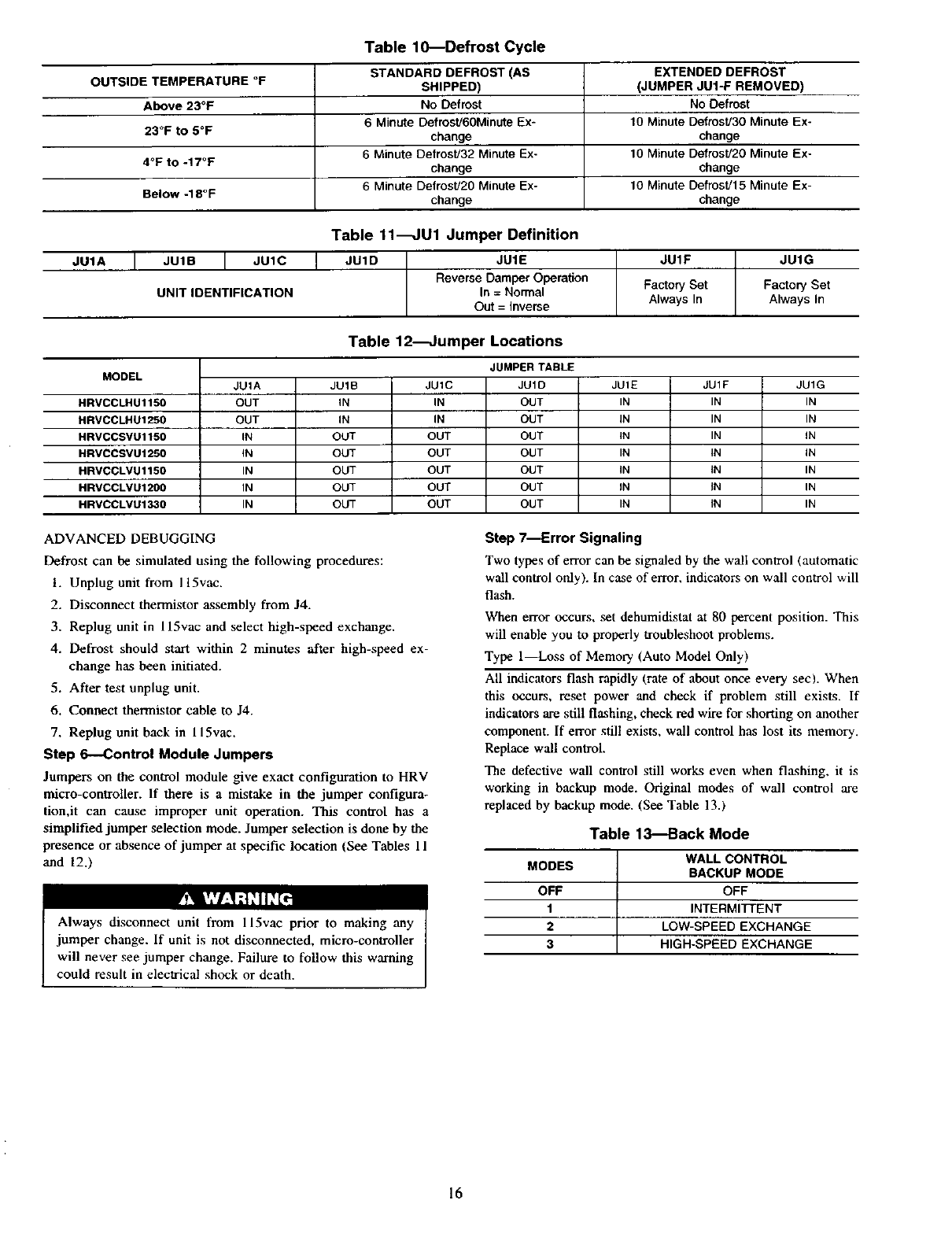
of the defrost cycle depends on outdoor temperature (see Table
10).
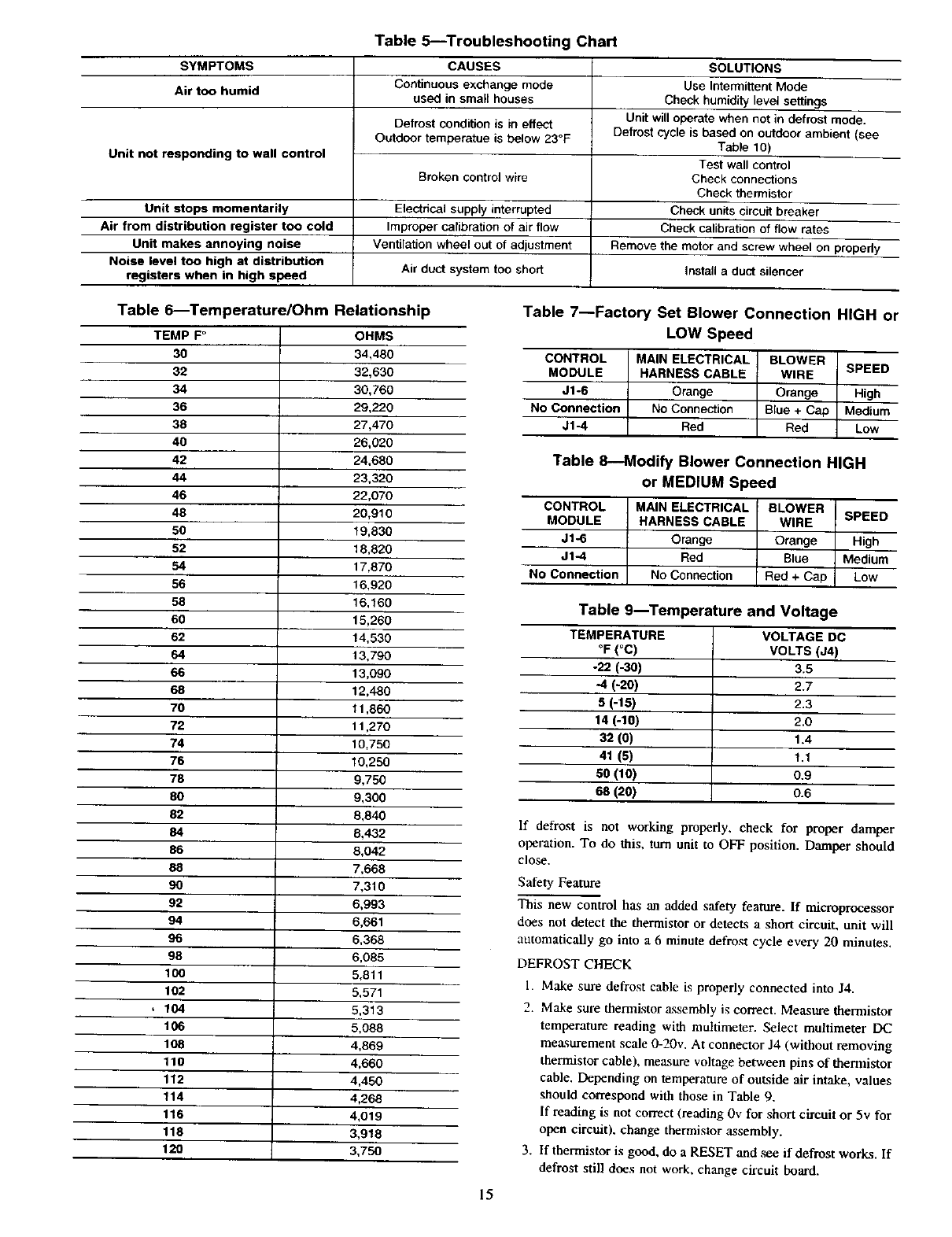
Table 5_Troubleshooting Chart
SYMPTOMS
Air too humid
Unit not responding to wall control
CAUSES
Continuous exchange mode
used in small houses
Defrost condition is in effect
Outdoor temperatue is below 23°F
Broken controlwire
Unit stops momentarily Electncal supply interrupted
Air from distribution register too cold Improper calibration of air flow
Unit makes annoying noise Ventilation wheel out of adjustment
Noise level too high at distribution Air duCt system too short
registers when in high speed
SOLUTIONS
Use Intermittent Mode
Check humidity level settings
Unit will operate when not in defrost mode.
Defrost cycle is based on outdoor ambient (see
Table 10)
Test wall control
Check connectior_s
Check thermistor
Check units circuit breaker
Check calibration of flow rates
Remove the motor and screw wheel on propedy
install a duct silencer
Table 6_Temperature/Ohrn Relationship
TEMPF ° OHMS
30 34,480
32 32,630
34 30,760
36 29,220
38 27,470
40 26,020
42 24,680
44 23,320
46 22,070
48 20,910
50 19,830
52 18,820
54 17,870
56 16,920
58 16,160
60 15,260
62 14,530
64 13,790
66 13,090
68 12,480
70 11,860
72 11,270
74 10.750
76 10,250
78 9,750
80 9,300
62 8,840
84 8,432
86 8,042
88 7,668
90 7,310
92 6,993
94 6,661
96 6,368
98 6,085
100 5,811
102 5,571
,104 5,313
106 5,088
108 4,869
110 4,660
112 4,450
114 4,268
116 4,019
118 3,918
120 3,750
Table 7--Factory Set Blower Connection HIGH or
LOW Speed
CONTROL
MODULE
J1-6
No Connection
J1-4
MAIN ELECTRICAL BLOWER
HARNESS CABLE WIRE
Orange Orange
NO Connection Blue + Cap
Red Red
SPEED
High
Me_um
Low
Table 8--Modify Blower Connection HIGH
or MEDIUM Speed
CONTROL
MODULE
Jl_
J1-4
No Connection
MAIN ELECTRICAL BLOWER
HARNESS CABLE WIRE
Orange Orange
Red Blue
NO Connection Red + Cap
SPEED
High
Medium
Low
Table 9_Temperature and Voltage
TEMPERATURE
°F(oc)
-22 (-30)
-4 (-20)
8(-16)
14 (-10)
32 (O)
41 (5)
50 (10)
68 (20)
VOLTAGE DC
VOLTS (J4)
3.5
2.7
2.3
2.0
1.4
1.1
0.9
0.6
If defrost is not working properly, check for proper damper
operation. To do this, turn unit to OFF position. Damper should
close.
Safety Feature
This new control has an added safety feature. If microprocessor
does not detect the thermistor or detects a short circuit, unit will
automatically go into a 6 minute defrost cycle every 20 minutes.
DEFROST CHECK
1. Make sure defrost cable is properly connected into J4.
2. Make sure thermistor assembly is correct. Measure thermistor
temperature reading with muhimeter. Select multimeter DC
measurement scale 0-20v. At connector J4 (without removing
thermistor cable), measure voltage between pins of thermistor
cable. Depending on temperature of outside air intake, values
should correspond with those in Table 9.
If reading is not correct (reading llv for short circuit or 5v for
open circuit), change thermistor assembly.
3. If thermistor is good, do a RESET and ,see if defrost works. If
defrost still does not work, change circuit board.
15
OUTSIDE TEMPERATURE °F
Above 23°F
23°F to 5°F
4°F to -17°F
Below -18°F
Table 10---Defrost Cycle
STANDARD DEFROST (AS
SNIPPED)
No Defrost
6 Minute DefrosU60Minute Ex-
change
6 Minute DefrostJ32 Minute Ex-
change
6 Minute DefrosU20 Minute Ex-
change
EXTENDED DEFROST
(JUMPER JUI-F REMOVED)
NO Defrost
10 Minute Defrost/30 Minute Ex-
change
10 Minute Defrost/20 Minute Ex-
change
10 Minute Defrost]15 Minute Ex-
change
JUIA
Table 11_U1 Jumper Definition
JU1B _JUIC
UNITIDENTIFICATION
J JUID JUIE
Reverse Damper Operation
In = Normal
Out = Inverse
JUIF
Factory Set
Always In
JUIG
Factory Set
Always In
MODEL
HRVCCLHU1150
HRVCCLHU1250
HRVCCSVU1150
HRVCCSVU1250
HRVCCLVU1150
HRVCCLVU1200
HRVCCLVU1330 :
Table 12_umper Locations
JU1A
OUT
OUT
IN
iN
IN
IN
IN
JU1B
IN
IN
OUT
OUT
OUT
OUT
OUT
JU1C
IN
IN
OUT
OUT
OUT
OUT
OUT
JUMPER TABLE
JU1D
OUT
OUT
OUT
OUT
OUT
OUT
OUT
JUIE
IN
IN
IN
IN
IN
JN
IN
JU1F
IN
IN
IN
IN
iN
IN
IN
JU1G
IN
IN
IN
iN
IN
IN
IN
ADVANCED DEBUGGING
Defrost can be simulated using the following procedures:
1. Unplug unit from 115vac.
2. Disconnect thermistor assembly from J4.
3. Replug unit in 115vac and select high-speed exchange.
4. Defrost should start within 2 minutes after high-speed ex-
change has been initiated.
5. After test unplug unit.
6. Connect thermistor cable to J4.
7. Replug unit back in 115vac.
Step 6--Control Module Jumpers
Jumpers on the control module give exact configuration to HRV
micro-controller. If there is a mistake in the jumper configura-
tion,it can cause improper unit operation. This control has a
simplified jumper selection mode. Jumper selection is done by the
presence or absence of jumper at specific location (See Tables 11
and 12.)
Always disconnect unit from 115vac prior to making any
jumper change. If unit is not disconnected, micro-controller
will never see jumper change. Failure to follow this warning
could result in electrical shock or death.
Step 7--Error Signaling
Two types of error can be signaled by the wall control (automatic
wall control only). In case of error, indicators on wall control will
flash.
When error occurs, .set dehumidistat at 80 percent position. This
will enable you to properly troubleshoot problems.
Type l_Loss of Memory (Auto Model Only)
All indicators flash rapidly (rate of about once every sec). When
this occurs, reset power and check if problem still exists. If
indicators are still flashing, check red wire for shorting on another
component. If en'or still exists, wall control has lost its memory.
Replace wall contlol.
The defective wall control still works even when flashing, it is
working in backup mode. Original modes of wall control are
replaced by backup mode. (See Table 13.)
Table 13---Back Mode
MODES
OFF
1
2
3
WALL CONTROL
BACKUP MODE
OFF
INTERMITTENT
LOW-SPEED EXCHANGE
HIGH-SPEED EXCHANGE
16
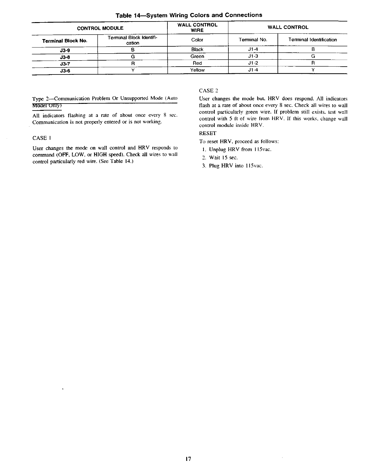
Table 14---System Wiring Colors and Connections
WALL CONTROL WALL CONTROL
CONTROL MODULE WIRE
Terminal Block Identifi- Color Terminal NO. Terminal Identification
Terminal Block No. cahon
J3-9 BBlack J1-4 B
J3-8 G Green J1-3 G
J3-7 RRed J1-2 R
J3-6 y Yellow J1-4 Y
Type 2--42ommunication Problem Or Unsupported Mode (Auto
MOdel unly_
All indicators flashing at a rate of about once every 8 sec,
Communication is not properly entered or is not working.
CASE 1
User changes the mode on wall control and HRV responds to
command (OFF, LOW, or HIGH speed). Check all wires to wall
control particularly red wire. (See Table 14-.)
CASE 2
User changes the mode but, HRV does respond. All indicators
flash at a rate of about once every 8 sec. Check all wires to wall
control particularly green wire. If problem still exists, test wall
control with 5 ft of wire from HRV. If this works, change wall
control module inside HRV.
RESET
To reset HRV, proceed as follows:
l. Unplug HRV from 115vac.
2. Wait 15 sec.
3. Plug HRV into 115vac.
17
DEFROST
TEMPERATURE
SENOR
CONNECTION DIAGRAM LOGIC DIAGRAM
........ BLK ............ WALL CONTROL
=....... G WALL CONTROL 1 NOTE 1 5
I q..... R ............... WALL CONTROL
I i=] = I= Y WALL CONTROL__
lil , OVERR'OESW_TCH1
,q OVERRIOE SWITCH OPTIONAL
I i I ' , ......... OVERRIDE LED NOTE 5
'I: I
i _ 1 I L
,_ i q ,
-- _ ,i i = ,NOTE 4
, i i q ,
T1
ELECTRONIC ASSEMBLY
NOTES
I CONTROLS/_VAIt J_BLE. SEE _NSTALL_TION MANUAL
( LOW VCLTAGE ONLY 12 VOC }
2ov6o., : J_3.._ _NEUTRAL
-- ...................................... ; MED M1
INC
J=l 6 ; HIGH j1 1
!Jl 4 ! ,ow
RELAY RELAY Pi
I
i
I
I_ --. ELECTRONIC ASSEMBLY ...........
F_CTORY _ET WI RING FOR S_OWER SPEED SEL_C13_N 18HIgH A N(
LOW MEOlUM SPEED CAN 8E SELEC_rED INff_D OF LCW Sp_ED
DISCONNECT RED WIRE FROM THE MOTOR REO TAR AND CONNECT
_ TRE M_TOR BLUE _p
3fF ANY OF THE ORI_tN_L WIRE¸ AS _UPt' LIEO, MUST OE REPLIED
USE TI4E SAME OR E_IVALENT WIRE
•U_E F_C_DRy 5UPPLIE_ p_tOTECTIVE Tt,_lNn
-- LINE VOLTAGE
..... LOWVOLTAGE
AND F_ELOWIRE
COLORCODE
RRED BK BLACK
VVIOLET BL 8LACK
w WHIT_ GY GR_Y
yYELLOW 0 ORANGE
BN BROWN GGREEN
NC NO CONNECTION
5 FILL9 WlRtNG MUST ¢_pkY WqTHA_UCABLE _Dt_&
ORDiNAtE8 AND REGU_T_&
jUI OE FROST TIME
JUMPER TABLE i I _ _NUTE$
l'_p£
JUrA Ju_8 JUIC JUlD _UIE JUIF JU_ 5,C 15C _O,C
OJT OUT OUT HRVCCLHUt _BO A&_ 532 _20
_,VJ_E C._ :.AN_E CH_,SE ._rK_E oU_ C_S _LL_,pES Ir')a _0._0 _0_S
RJNCTION TABLE RELAY
A
MODE K1 K2 K4 K5
intlrrr_tent 0 0 O0
Exchat_ge LOW 1 0_ I
Exchange High 1 1 1
Circulation low 010
CirCulation hKjh 1110
Defrosl Cycle 11I 0
Off 0000
0= Relay coil md_energized
1=Relay coil ts energized
NS = Not supported
A00031
Fig, 27--Wiring Diagram for Models: HRVCCLHU1150, and HRVCCLHU1250
CONNECTION DIAGRAM LOGIC DIAGRAM
--LINEVOLTAGE
- --LC_qVOLTAGE
AND FIELD WIRE
----OPTIONAL COLOR CODE I
RRED BK BLACK
V VIOLET BL BLACK
W WHITE GY GREY
YYELLOW OORANGE
BN BROWN G GREEN
N¢ NO CONNECTION
120VAC
_m
_R
INTERLOCK
$_TCH
i--..
iJ1_
LOW
RELAY I
r
i ' i
iREU_Y
.................. ¢ONT_ fiO_RD ............. f
,, ,,JUl 2
_M_-R TA_-E _ I
_BCOE_ G_OO_L O_
Z_
JUIA _IB JglC _ID _JIE _IF #J_G
OUT OUT OUT IN IN HRV¢CSVU11_ A
OUT OUT O_T IN _ HRVCCSVU12_ A
OUT OUT OUT IN IN H_VCCLVU_I_
IN C_T _JT OUT iN _ HRVCCLVUI_
I
OUT I OUT OUT IN IN H_VCCLVUI_0
I
NOTES
I"THREECONTROL_AVAI_BL£S££THEINSTALLATIONM_NUAL
ILOWVOLTAG_ O_LYI2V_C)
2. FAN MOTOR 2I$ USED ONLY WITH HRVCCLHU125O _RVCCLVUI _C_
AND HR_¢CLVU_330
30Ak_PER MOTOR 2IS USED ONLY WlTHRV¢¢_V_ 200 AN D
HRVCC_VU 1330
4. IF ANY OF THE ORIGINAL WIRE _S SUPPLIED. MUST BE
REPLA¢£0_ U_E TH_ SAM_ OR EOUtVALENT WIRE
S•FACTORY S_T WIRING _OR BLOWER SpEE_ SELECTION IS HIGH AND
L_W M£OIUM SPE_D C_N BE S_LECTED IN_TE_D OF LOW $_EED
DISCONNECT RED WIRE FROM MOTORIS I RED TAP AND CONNECT TO
M<_TOR_$) BLUE TA_
FUNCTION TABLE RELAy
A
MOOE K1 K2 K5
Inlarmittent 00 1
Exchange Low i0 O
Exchange High IO
C_¢ul_t _n low I01
Cin:u_ation high 1 1 1
D_frosl Cycle 1 _ 1
Off 0 0 1
0•Relay coil _s d_, energized
1=Relay ¢oil _s energized
NS = Noi supported
A00089
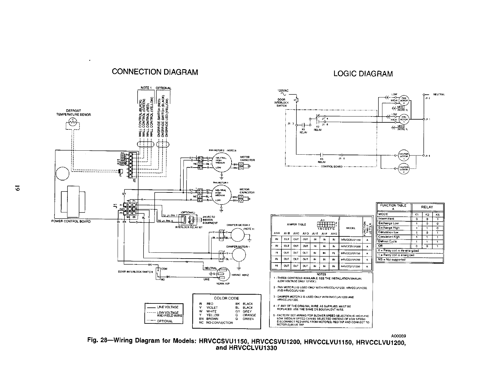
Fig. 28--Wiring Diagram for Models: HRVCCSVU1150, HRVCCSVU1200, HRVCCLVU1150, HRMCCLMU1200,
and HRVCCLVU1330
mNEUTRAL
JI I
O
D
(120.6)
23/16t--,-I
(56.2)
4 PLCS-_-
(608.0)
1
(25.4)
2 PLCS
30 1/4t
(768.3)
2 s/16t
(56.7)
,/_5 7/8t DIA
1
(460_') I Ill
_15t
16 7/8, (381.0)
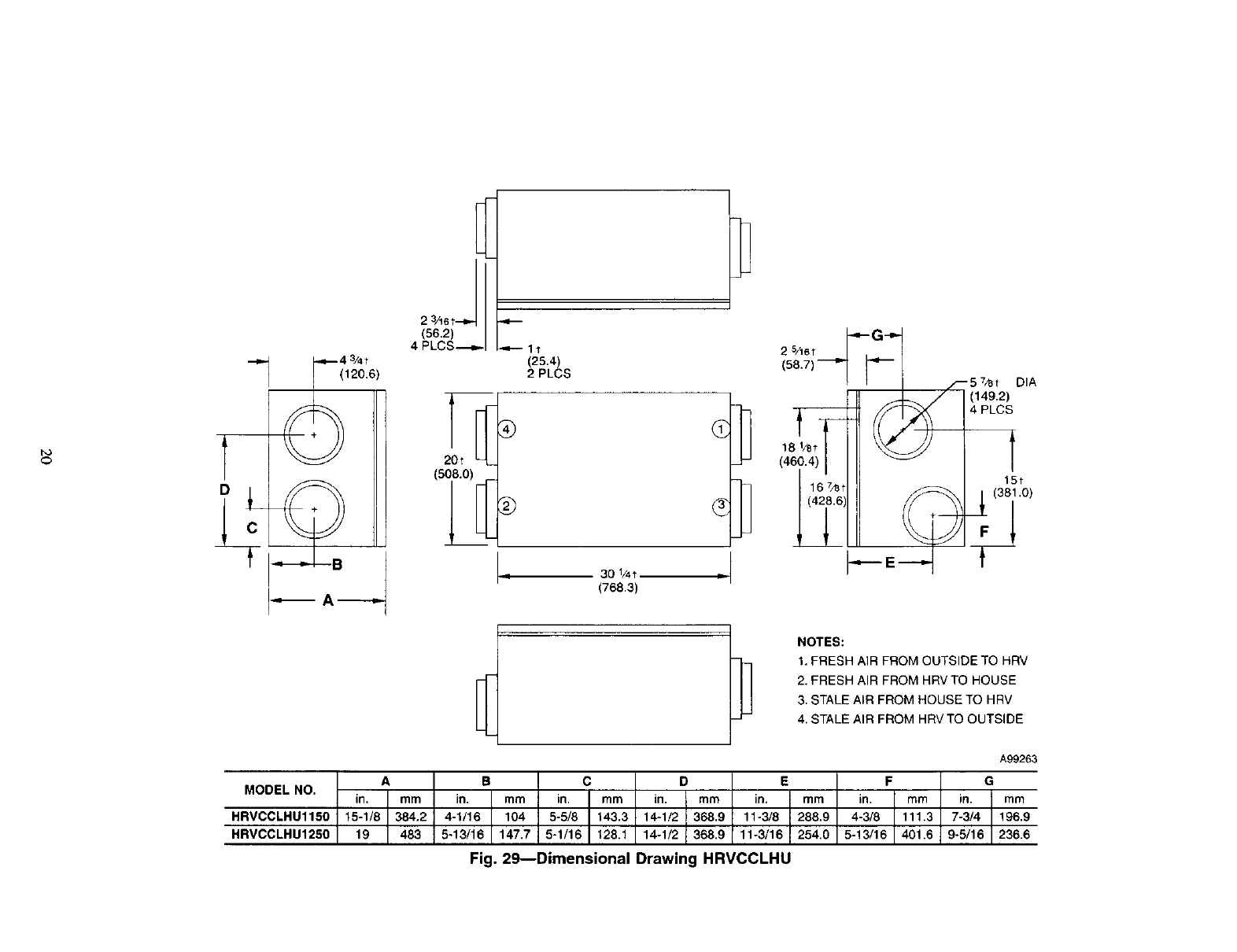
NOTES:
1. FRESH AIR FROM OUTSIDE TO HRV
2. FRESH AIR FROM HRVTO HOUSE
3. STALE AIR FROM HOUSE TO HRV
4. STALE AIR FROM HRV TO OUTSIDE
MODEL NO.
HRVCCLHU1150
HRVCCLHU1250
A99263
jmm 196.9
236.6
Fig. 29--Dimensional Drawing HRVCCLHU
FJ
4 9/_e_
[115.9)} --b
C
l"J
[25.4]
2 PLCS
57/e" DIA
L._ [149.2]
2 PLCS
i
--
__193/4" --
[5ol.7]
,,r_q, _-
221/16 _
[560.4]
//
ji s
S / _ I
/ _ q_
3¾6
[81.o]
t
115/16"
[23.8] 2 3/16"
[55.6]
-4 PLCS
T
27"
[685,8]
1
//
//
WALL
CONTROL
(_ WIRING
3/a"DIA
[9.5]
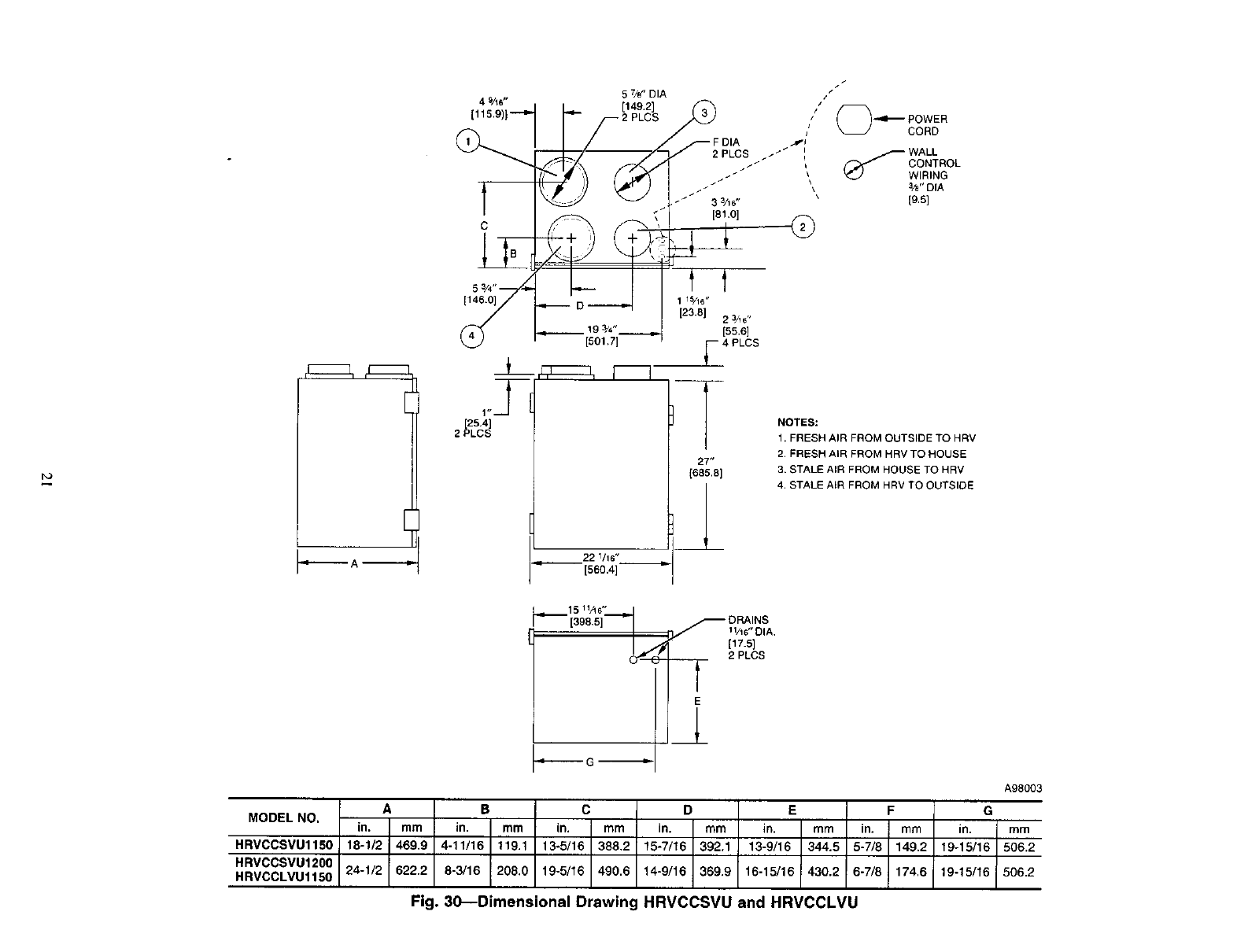
NOTES:
1. FRESH AIR FROM OUTSIDE TO HRV
2. FRESH AIR FROM HRV TO HOUSE
3. STALE AIR FROM HOUSE TO HRV
4. STALE AIR FROM HRV TO OUTSIDE
_1511/! 6"
[398,5]_
._..--,-.-.-- G..-.-----_
__ 2 PLCS
E
A B C
MODEL NO. in. mm in. mm in. mm in.
HRVCCSVU1150 18-1/2 469.9 4-11/16 119.1 13-5/16 388.2
HRVCCSVU1200
HRVCCLVU1150 24-1/2 622.2 8-3/16 208.0 19-5/16 490.6
A98003
D E F G
mm in. mm in. mm in. mm
15-7/16 392.1 13-9/16 344.5 5-7/8 149.2 19-15/16 506.2
14-9/16 369.9 16-15/16 430.2 6-7/8 174.6 19-15/16 506.2
Fig. 30--Dimensional Drawing HRVCCSVU and HRVCCLVU
8 1/8"
[206.4]
2 PLCS_',
13/t6"
'[147.6]
.151/2.
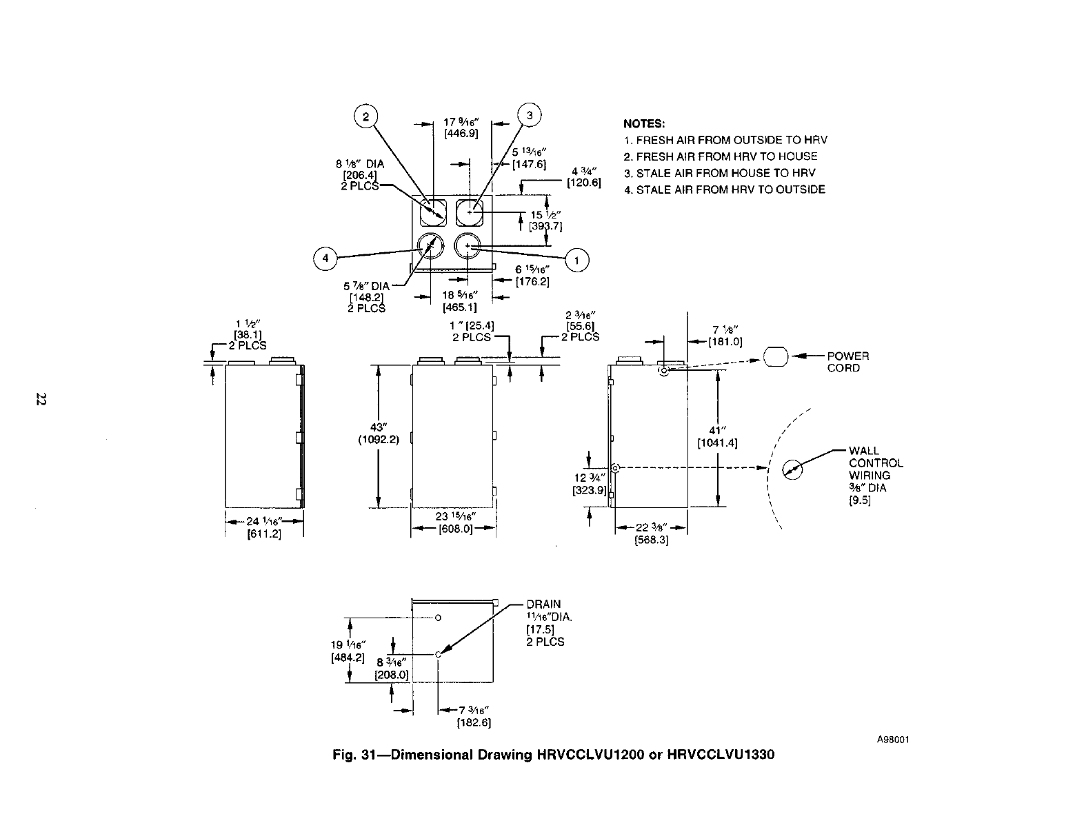
NOTES:
1. FRESH AIR FROM OUTSIDE TO HRV
2. FRESH AIR FROM HRV TO HOUSE
3. STALE AIR FROM HOUSE TO HRV
4. STALE AIR FROM HRV TO OUTSIDE
b_
1 1/2"
[38.1]
!_'---2 PLGS
t
24 1/16"'_"
[611.2]
C148.2]
2 PLCS
T
43"
(1092.2)
6 15/16"
185/16" _ [176.2]
[465.1 ] 2 3/16"
1 " 125.4] [55.6]
2 PLCS q F2 PLCS
L
123/4"
[323.91
23 WW'
.,,.--- [608.0]--_.
7 1/_,,
,_--[181.0]
(_ -..11---- POWER
....... _ CORD
////
41" /'
[1041.4] /WALL
I/_ CONTROL
........ "I _-_/ WIRING
3/8" DIA
\
\
t
19 1/16"
[48i'2] [208.0]
1%6"DIA.
[17.5]
2 PLCS
[182.6]
Fig. 31--Dimensional Drawing HRVCCLVU1200 or HRVCCLVU1330
A98001
SERVICE TRAINING
Packaged Service Training programs are an excellent way to increase your
knowledge of the equipment discussed in this manual, including:
* Unit FamiliarizaUon ° Maintenance
• Instaila'don Overview • Operating Sequence
A large seleclion of product, theory, and skills programs is available, using popular
video-based formats and materials. All include video and/or slides, plus companion
book.
Classroom Service Training plus "hands-on" the products in our labs can mean
increased confidence that really pays dividends in faster troubleshoo_ng, fewer
callbacks. Course descriptions and schedules are in our catalog.
CALL FOR FREE CATALOG 1-800-962-9212
[ ] Packaged Service Training [ ] Classroom Service Training
A94328
23

Copyright 2000 CARRIER Corp. • 7310 W, Morns St. •Indianapolis, IN 46231 hrvlsi
Manufacturer reserves the right to discontinue, or change at any time, specifications or designs without notice and without incurring obligations.
"i_12 PC 101 Catalog NO. 03HR-VC3 Printed in U.S.A, Form HRV-2SI Pg 24 5-00 Replaces: HRV-1SI
a
