CARRIER Controls And HVAC Accessories Manual L0211035
User Manual: CARRIER CARRIER Controls and HVAC Accessories Manual CARRIER Controls and HVAC Accessories Owner's Manual, CARRIER Controls and HVAC Accessories installation guides
Open the PDF directly: View PDF ![]() .
.
Page Count: 4
HUMIDITRACTMHUMIDIFIERCONTROL
Safety and Installation Instructions
READ COMPLETE INSTALLATION INSTRUCTIONS AND TEMPLATE BEFORE STARTING,
Attention Installer: This product must be installed by a qualified heating and air conditioning contractor.
Failure to do so couldresult in serious injury from electrical shock.
THESEINSTALLATIONINSTRUCTIONSAREFORTHEHUMIDITRACTM HUMIDIFIERCONTROLONLY!
ForHumidifierinstallation,follow HumidifierInstallationInstructions,
_._A
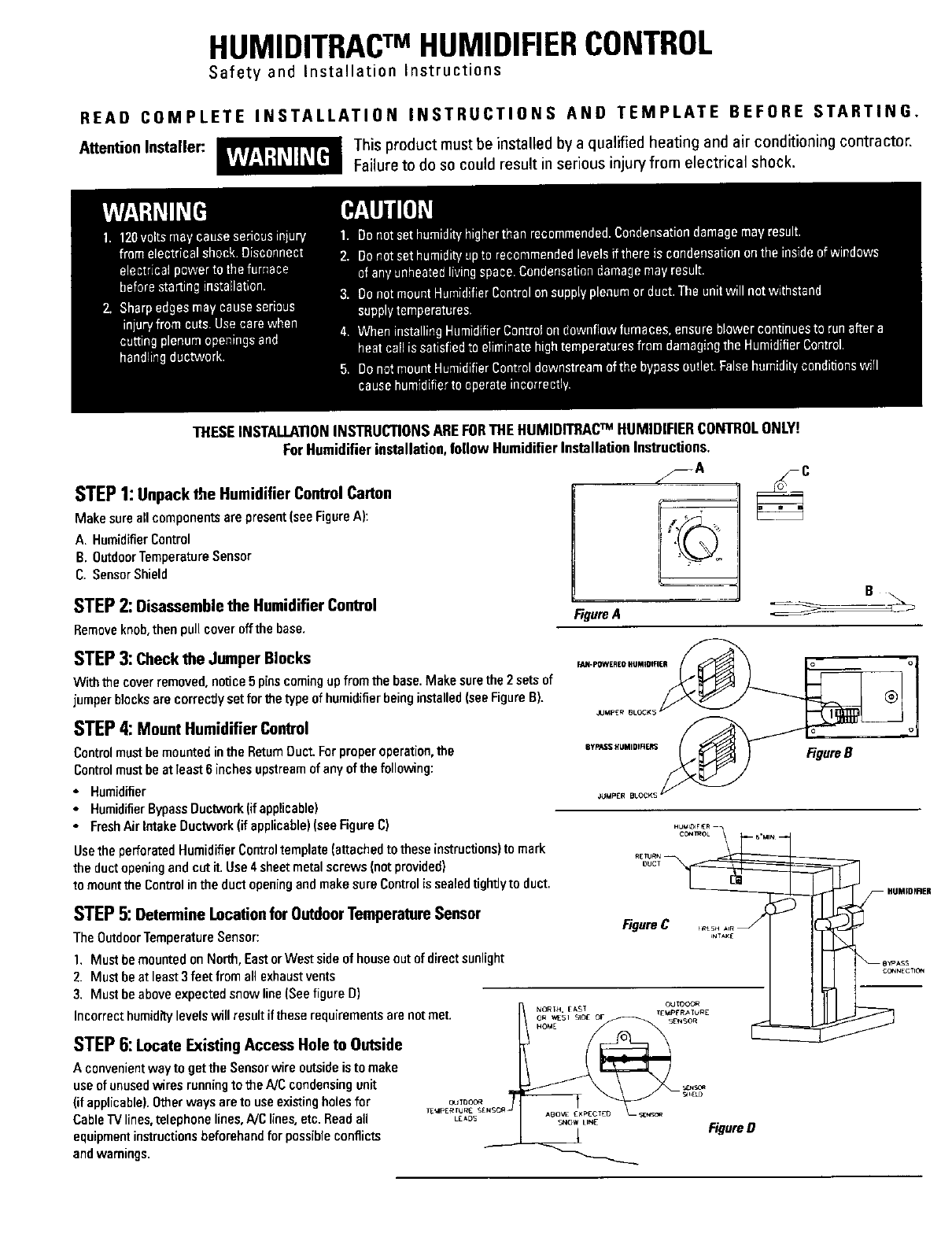
STEP1:Unpack the Humidifier ControlCarton
Make sure all componentsare present(seeFigureA):
A. HumidifierControl
B. OutdoorTemperatureSensor
C. SensorShield
STEP2:Disassemble the Humidifier Control
Removeknob,then pull coveroffthe base•
%
Figure A
STEP3:Check the Jumper Blocks
With the coverremoved, notice 5 pinscomingup from the base.Make surethe 2sets of
jumper blocks are correctlysetfor theP/pe of humidifierbeing installed(seeFigureB).
STEP4: Mount Humidifier Control
Controlmustbemounted inthe ReturnDuct.Forproperoperation,the
Controlmust be atleast 6inches upstreamof anyof the following:
• Humidifier
• HumidifierBypassDuctwork(ifapplicable)
• FreshAirIntakeDuctwork(if applicable)(see FigureC)
Usethe perforated HumidifierControltemplate(attachedto these instructions)to mark
the ductopeningand cutit.Use 4 sheetmetalscrews (notprovided)
to mountthe Control intheduct openingand makesureControl is sealeddghtJyto duct.
OUCT
FigureB
STEP5:Determine Location for Outdoor Temperature Sensor
TheOutdoorTemperatureSensor:
1. Must bemountedon North,EastorWest sideof houseout ofdirect sunlight
2. Must beat least 3feet from all exhaustvents
3. Must be above expectedsnow line (Seefigure D)
Incorrect hamid_ levels will resultif these requirements are not met.
STEP6:Locate Existing Access Hole to Outside
Aconvenientway to get the Sensorwire outsideis to make
useofunusedwires runningto the NC condensingunit
(if applicable).Otherwaysare to useexistingholesfor
CableTVlines,telephonelines,A/Clines, etc. Readall
equipmentinstructionsbeforehandfor possibleconflicts
andwamings.
FigureC
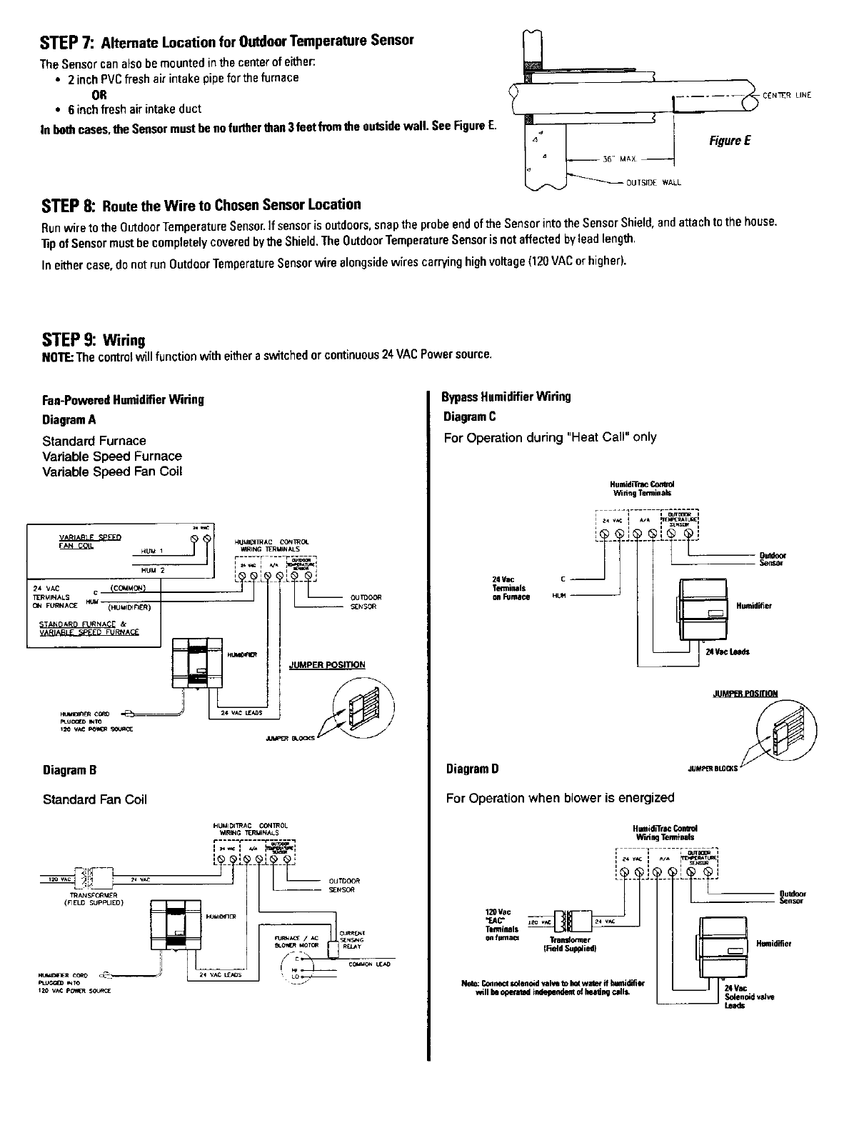
STEP7: Alternate Location for Outdoor Temperature Sensor
The Sensor canalsobe mounted in thecenter of either:
•2 inchPVCfresh air intakepipeforthe furnace
OR
•6 inchfreshair intakeduct
In bothcases,the Sensormustbe nofurther than3feet fromthe outsidewall, SeeFigureE.
STEP8: Routethe Wire to ChosenSensor Location
M <
7 ,......
FigureE
a _6,, MAX --
OUTSIDE WALL
Hunwire tothe OutdoorTemperatureSensor.If sensoris outdoors,snaptheprobeendof theSensor intothe SensorShield, andattachtothe house.
l_p ofSensor mostbe completelycoveredbythe Shield.The OutdoorTemperatureSensor is notaffectedbylead length.
In eithercase,do not runOutdoorTemperatureSensorwire alongsidewires carryinghighvoltage(120VACorhigher).
STEP9: Wiring
NOTE:Thecontrolwillfunction with eithere switchedor continuous24VACPower source.
Fan-PoweredHumidifierWiring
DiagramA
Standard Furnace
Variable Speed Furnace
Variable Speed Fan Coil
iq w_
HUMIOI ]R AC L'ON _T_OL
HUM2 i : i I =--_ 1
TERMINALSCI I / i / L___ oumooe
HulioIrl_ JUMPER POSITION
DiagramB
Standard Fan Cotl
HillilDIl_ AC CON IROL
_4RING TERIIIN_.$
,r---i + T_-I
OUTDOOR
-- SENS(3#_
f_c_" \
_11_ R _ --# I 14 v^c L£_OS
_TO
BypassHumidifierWiring
DiagramC
For Operation during "Heat Call" only
24 Y_.
Terminals
on rmmace
Humid_rac
W_HagTemminals
_
H_LeedsHUmidifier
DiagramD
JUMPER BLOCKS
For Operation when blower is energized
Humid_ra_ Cord_ol
Wit_n9Tenmnals
.,<...,+,.=
Te_ls
IRMd Supplied)
Note;Connlict1olenold"_zltetokotwatereFamlidifier
willlie oFerat_ i_le_+_i ol;_ng ceUi
Hamidifier
_4Va_dva_e
u_a_s
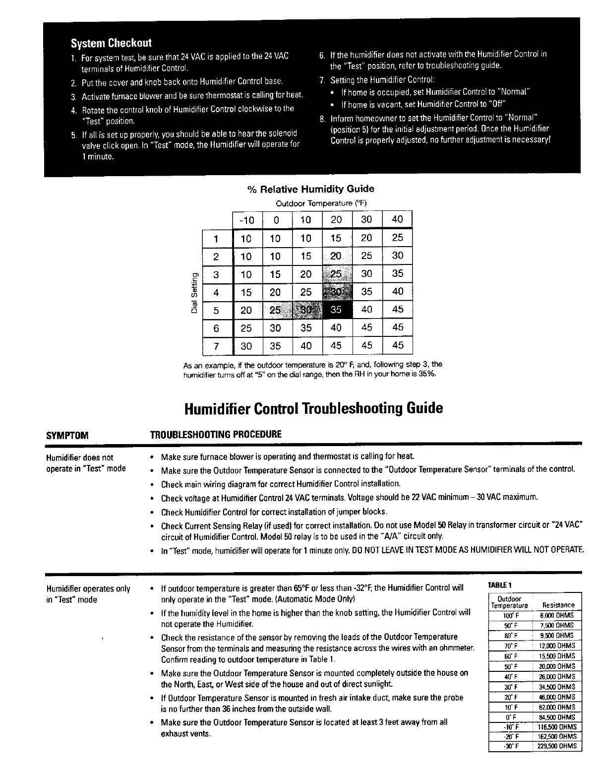
% Relative Humidity Guide
Outdoor Temperature(°F)
-10 0 10 20 30 40
1 10 10 10 15 20 25
2 10 10 15 20 25 30
3 10 15 20 30 35
4 15 20 25 35 40
5 20 11.1 40 45
6 25 30 35 40 45 45
7 30 35 40 45 45 45
As an example, if the outdoor temperature is 20° F, and, following step 3, the
humidifier turns off at "5" on the dial range, then the RH in your home is 35%,
SYMPTOM
Humidifierdoesnot
operatein"Test" mode
HumidifierControlTroubleshootingGuide
TROUBLESHOOTINGPROCEDURE
•Make sure furnace blower is operatingandthermostatis callingfor heat.
•Make sure the OutdoorTemperatureSensor is connectedto the "OutdoorTemperatureSensor"terminalsof thecontrol.
• Check mainwiring diagramfor correctHumidifierControl installation.
•Check voltageat HumidifierControl24 VACterminals.Voltageshould he 22VACminimum- 30VACmaximum.
•Check HumidifierControlfor correctinstallationofjumperblocks.
• Check Current Sensing Relay(if used)for correctinstallation.Do notuse Model50 Relayintransformercircuitor "24 VAC"
circuitof HumidifierControl.Model50 relay isto be usedinthe "A]A" circuitonly.
•In"Test" mode,humidifier will operatefor 1 minuteonly.DONOTLEAVEINTESTMODEASHUMIDIFIERWILL NOTOPERATE.
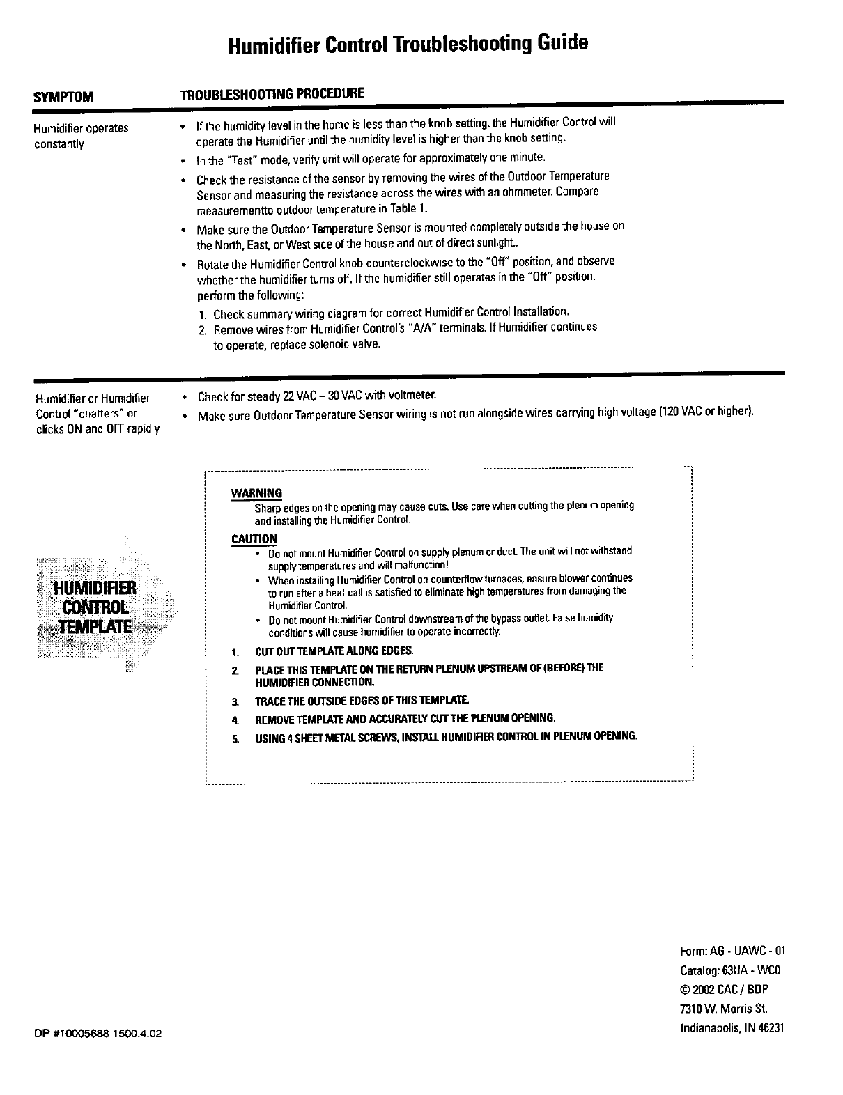
Humidifieroperatesonly
in "Test"mode
•If outdoortemperatureis greaterthan65°Forlessthan-32°F,theHumidifierControl will
only operate inthe "Test" mode.(AutomaticMode Only)
• If the humiditylevel inthe homeis higher than the knob setting, the HumidifierControl will
not operate the Humidifier.
• Check the resistance ofthe sensor by removingthe leads of the OutdoorTemperature
Sensorfromthe terminals and measuringthe resistance across the wires with an ohmmeter.
Confrm readingto outdoor temperature inTable 1.
• Make sure the Outdoor TemperatureSensor is mounted completely outside the houseon
the North, East,or West side of the house and out of direct sunlight.
• If OutdoorTemperature Sensor is mounted in fresh air intake duct, make surethe probe
is nofurther than 36 inchesfrom the outsidewall.
• MakesuretheOutdaorTemperatureSensorislocatedatleast3feetawayfroma]l
exhaustvents.
TABLE 1
Outdoor
Temperature Resistance
100=F 6,000 OHMS
90° F7,5_ OHMS
80°F 9,500 OHMS
70°F 12,000OHMS
60°F 15.500OHMS
50_F 20,0000HMS
4OOF 26,0000HMS
30=F 34,500OHMS
20"F 46,000OHMS
10=F 62.000OHMS
0=F 84,500OHMS
-1O'F 116,5000HMS
-20"F 162,500OHMS
-_°F 229,500OHMS
HumidifierControlTroubleshootingGuide
SYMPTOM
Humidiferoperates
constantly
TROUBLESHOOTINGPROCEDURE
Ifthe humiditylevelinthehomeislessthanthe knobsetting,the HumidifierControlwig
operatethe Humidifieruntilthe humiditylevel is higherthan the knobsetting.
Inthe "Test" mode,verifyunitwilloperatefor approximatelyone minute.
Checkthe resistanceof thesensorbyremovingthe wires oftheOutdoorTemperature
Sensorand measuringthe resistanceacrossthe wires withanohmmeter.Compare
measurementto outdoortemperatureinTable 1.
Make surethe OutdoorTemperatureSensor ismountedcompletelyoutsidethehouseon
the North,East,orWestsideofthe houseandoutofdirectsunlight..
Rotatethe HumidifierControlknobcounterclockwiseto the"Off"position,and observe
whetherthe humidifierturnsoff.If thehumidifierstill operatesinthe "Off" position,
performthe following:
1. Checksummarywiring diagramfor correctHumidifier ControlInstallation.
2. Removewires from HumidifierCoutrol's"NA" terminals.IfHumidifiercontinues
to operate,replacesolenoidvalve.
Humidifier orHumidifier • Checkfor steady 22VAC- 30VACwithvoltmeter.
Control"chatters"or • Make sureOutdoorTemperatureSensor wiringis notrunalongsidewires carryinghighvoltage(120VACor higher).
clicksONandOFFrapidly
.......................................................................................................................................
WARNING
Sharp edgeson the openingmay cause cuts.Use carewhen cuttingthe plenumopening
and installingthe HumidifierControl
CAUTION
• Do notmount HumidifierControlon supplyplenumor duct.The unitwill notwithstand
supplytemperaturesandwill malfunction!
•When installingHumidifier ContToIon counterflowfurnaces, ensureblowercontinues
to runafteraheatcall issatisfiedto eliminatehightemperaturesfrom damagingthe
HumidifierControl.
•Do not mount HumidifierControl downstreamof the bypassouttet. Falsehumidity
conditionswigcausehumidifierto operateincorrectly.
1. CUTOUTTEMPLATEALONGEDGES.
2. PLACETHISTEMPLATEONTHERE1URNPLENUMUPSTREAMOF(BEFORE)THE
HUMIDIFIERCONNECTION.
3. TRACETHEOUTSIDEEDGESOFTHIS 1TJMPLATE.
4. REMOVETEMPLATEANDACCURATELYCUTTHEPLENUMOPENING.
5. USING4 SHEETMETALSCREWS,INSTALLHUMIDIRERCONTROLIN pLENUMOPENING.
DP #10005688 1500.4.02
Form:AG-UAWC- 01
Catalog:63UA- WC0
© 2002CAC/BDP
7310W. Morris St.
Indianapolis,IN48231
