CARRIER Home Generator Manual L0520292
User Manual: CARRIER CARRIER Home Generator Manual CARRIER Home Generator Owner's Manual, CARRIER Home Generator installation guides
Open the PDF directly: View PDF ![]() .
.
Page Count: 44

I
Air-coo_ed Automatic
Standby Generators
Mode_: ASPA×I CCA015
(13 kW NG, 15 kW LP)
©
*This manua_ should remain with the unit.*
Not intended for use as Primary Power in place of utility
or in life=support applications.
DEADLY EXHAUST FUMES. OUTDOOR iNSTALLATiON ONLY!
Thank you for purchasing this model of tile Carrier
product line. This model is a compact, high per%f-
inance, air-cooled, engine-driven generator designed
to automatically supply electrical power to operate
critical loads during a utility power failure.
This unit is factory installed in an all-weather, metal
enclosure that is intended exclusively for outdoor
installation. This generator will operate using either
vapor withdrawn liquid propane (LP) or natural gas
(NG).
This unit meets the 1998 and later California
emissions regulations. To ensure that the engine
continues to meet these regulations, refer to the
following information and instructions in this
owner's manual.
@R[AD Tills MANUAl THOROUGHLY
If any portion of this manual is not understood,
contact the nearest dealer for starting, operating and
servicing procedures.
ThrolNllout tiffs publication, and on tags and decals
affixed to tlle generator, DANGER, WARNING,
CAUTION and NOTE blocks are used to alert person-
nel to special instructions about a particular opera-
tion that may be hazardous if performed incorrectly
or carelessly. Observe them carefully. Tlleir defini-
tions are as lhllows:
After this heading, read instructions that, if not
strictly complied with, wilt resuR in serious per-
sonal injury, including death, in addition to severe
propertydamage.
WARNING
After this heading, read instructions that, if not
strictly complied with, may resuJt in serious per-
sonal injury or property damage.
CAUTION
After this heading, read instructions that, if not
strictly complied with, could result in damage to
equipment and/or property.
NOTE:
After this heading, read explanatory statements
that require special emphasis.
These safety warnings cannot eliminate the haz-
ards that they indicate. Common sense and strict
compliance with the special instructions while
performing the service are essential to preventing
accidents.
Four commonly used safety sy_nbols accompany the
[)ANGER, WARNING and CAUTION blocks. The type
of inlhrmation each indicates follows:
Z_ This symbol points out important safety infor-
mation that, if not followed, could endanger
personal safety and/or property of others.
This symbol points out potential explosion haz-
ard,
/_k This symbol points out potential fire hazard,
Z_ This symbol points out potential electrical shock
hazard.
The operator is responsible for proper and sale use
f the equipment. The manufacturer strongly recom-
mends that the operator read this Oumeis Manua_
and thoroughly understand all instructions belbre
using this equipment. The manufi_eturer also strong-
ly recommends instructing other users to properly
start and operate the unit. This prepares thenl if they
need to operate the equipment in an emergene_t
This manual contains pertinent owner's information,
including warranty; electrical diagrams, exploded
views and lists of repair parts, for modeh
o Model ASPAXICCA015 - 13 kW NG, 15 kW LP, V;
hvin G_ft990 Engine
OPERATION AND MAINTENANCE
It is the operator's responsibility to perlorm all salety
checks, to make sure that all maintenance for sale
operation is perlormed promptly; and to have the
equipment checked periodically by a dealen Normal
maintenance service and replacement of parts are the
responsibility of the owner/operator and, as such, are
not considered deicers in materials or workmanship
within the terms of the warranty. Individual operating
habits and usage contribute to the need for mainte-
nance service.
Proper maintenance and care of the generator ensures
a mininmm number of problems and keep operating
expenses at a mmimunL See a dealer for service aids
and accessories.
When the generator requires servicing or repairs,
simply contact a dealer for assistance. Service teelmi-
eians are factory-trained and are capable of handling
all service needs.
When contacting a dealer about parts and service,
always supply the complete model number and serial
number of the unit as given on its data decal, which
is located on the generaton
The Carrier Dealer is:
Dealer Name
Address
City State Zip
Model No, Serial No,
Table of Contents
15 kW Generator
TABLE 1
Untroduction ........................ Unside Front Cover
Read This Manual Thoroughly ........................ IFC
Contents .......................................................... IFC
Operation and Maintenance ............................ IFC
How to Obtain Service ..................................... IFC
Safety RuRes ........................................................ 2
Standards Index .................................................. 3
Section 1 -General information ................... 4
1.1 Unpaekin_Inspeetion .................................... 4
1.2 Location ........................................................ 4
1.3 Protection Systems ........................................ 4
1.4 System Set LED ............................................ 4
1.5 The Generator ............................................... 5
1.6 Specifications ................................................ 6
1.O. 1 Generator ........................................... (3
1.6.2 Engine ................................................ 6
1.7 Fuel Requirements and Recommendations ... 6
1.8 Fuel Consumption ......................................... G
1.9 Reeonfiguring the Fuel System ...................... 7
1.9.1 15 kW, 990ee Engines ........................ 7
1.10 Location ........................................................ 7
1.10.1 Generator ........................................... 7
1.10.2 Trans%r Switch .................................. 8
1.11 Battery Installation ........................................ 8
1.12 The Battery ................................................... 8
Section 2 - Post lnstaRation Start-up
and Adjustments .........................9
2.1 Before Initial Star_-up .................................... 9
2.2 Cheek Transfer Switch Operation ................. 9
2.3 Electrical Cheeks .......................................... 9
2.4 Generator _[_sts Under Load ....................... 10
2.5 CheeRing Automatic Operation .................... 10
2.G Adjusting the Regulator (Natural Gas Only).. 11
2.7 Engine Governor Adjustment ...................... 12
2.7.1 15kWUnits ..................................... 12
2.8 Voltage Regulator Adjustment ...................... 12
Section 3- Operation .................................... 12
3.1 Break-in Procedure ..................................... 12
3.2 Using the Auto/Ol1/Manual Switch ............... 13
3.2.1 "Auto" Position .................................. 13
3.2.2 "Off" Position .................................... 13
3.2.3 "Manual" Position ............................. 13
3.3 Automatic Transier Operation ..................... 13
3.3.1 12 VDC Accessory Outlet ................. 13
3.3.2 120 VAC GFCI Outlet ....................... 14
3.4 Sequence of Automatic Operation ............... 14
3.5 Manual Transfer Operation ......................... 14
3.5.1 Transler to Generator
Power Source ..................................... 14
3.5.2 Transter Back to Utility
Power Source ..................................... 15
3.6 Setting the Exercise Timer .......................... 15
3.7 Protection Systems ...................................... 15
3.7.1 Low Oil Pressure Switch .................. 15
3.7.2 High _[_mperature Switch ................. 15
3.7.3 Overerank ........................................ 1G
3.7.4 Overspeed ........................................ 1G
Section 4 - Maintenance ............................... 16
4.1 _51ses ........................................................... 16
4.2 Checking the Engine Oil Level ..................... 16
4.3 Changing the Engine Oil .............................. 16
4.3.1 Engine Oil Recommendations .......... 16
4.3.2 Oil Change Procedure ....................... 17
4.4 Changing the Oil Filter ................................ 17
4.5 Changing the Engine Air Cleaner ................. 17
4.5.1 15 kW Generators ............................ 17
4.6 Spark Plug{s) .............................................. 17
4.7 Battery Maintenance .................................... 18
4.8 Adjusting Valve Clearance ........................... 18
4.9 Cooling System ........................................... 19
4.10 Attention After Submersion ......................... 19
4.11 Corrosion Protection ................................... 19
4.11.1 Additional Corrosion Protection ....... 19
4.12 Out of Service Procedure ............................. 20
4.12.1 Removal From Service ...................... 20
4.12.2 Return to Service ............................. 20
4.13 Service Schedule ......................................... 21
Section 5 - Troubleshooting ........................ 22
5.1 Troubleshooting Guide ................................ 22
Section 6 - Mounting Dimensions ............. 23
Section 7- ElectricM Data ........................... 24
Section 8 -Exploded Views and
Parts Lists ................................... 28
Section 9-Warranty ..................................... 40
SAFETYRULES IMPORTANT SAFETY iNSTRUCTIONS
1SkW Generator
SAVE THESE INSTRUCTIONS - The manufacturer suggests that these rules for safe
operation be copied and posted in potential hazard areas. Safety should be stressed to all
operators, potentiai operators, service and repair technicians for this equipment.
Study these SAFETY RULES carefully betore
installing, operating or servicing this equipment.
Become familiar with this Owner's Manual and with
the unit. The generator can operate safely; efficiently
and reliably only if it is properly installed, operated
and maintained.
The manulacmrer cannot anticipate every possible
circumstance that might involve a hazard. The warn-
ings in this manual, and on tags and decals affixed to
the unit are, therefore, not all-inclusive. Any personal
injury or property damage resulting from the use of a
procedure, work method or operating technique not
specifically recommended by the manufacturer, shall
be the sole responsibility of the operator. Operators
who deviate from manufacturer recommended safety
procedures and operating techniques, or fail to take
the necessary precautions, do so at their own risk.
/_ Despite the safe design of this generator, oper-
ating this equipment imprudentJy, neglecting its
maintenance or being careless can cause pos-
sible injury or death, Permit onJy responsiMe
and capable persons to operate or maintain this
equipment
Z_ Potentially lethal voltages are generated by
these machines. Ensure all steps are taken to
render the machine safe before attempting to
work on the generator.
z_ Parts of the generator are rotating and/or hot
during operation. Exercise care near running
generators.
2
iN GENERALHAZARDS/5
.For satety reasons, the manuihemrer recommends
that the installation, initial start-up and mainte-
nance of this equipment is carried out by a deal-
en
o The engine exhaust Imnes contain carbon monox-
ide, which can be DEADLY. This dangerous gas, if
breathed in sufiieient concentrations, can cause
unconsciousness or even death. This exhaust
system must be installed properly; in strict com-
pliance with applicable codes and standards.
Following installation, do nothing that might ren-
der the system unsafe or in noncompliance with
such codes and standards.
o Keep hands, feet, clothing, etc., away from drive
belts, fans, and other moving or hot parts. Never
remove any ° drive belt or fan guard while the unit
is operating.
o Adequate, unobstructed flow of cooling and venti-
lating air is critical to correct generator operation.
Do not alter the installation or permit even partial
blockage of ventilation provisions, as this can seN-
ously affect safe operation of the generator. The
generator MUST be installed outdoors.
o When working on this equipment, remain alert
at all times. Never work on the equipment when
physically or mentally fatigued.
o Inspect the generator regularly, and contact the
nearest dealer for parts needing repair or replace-
ment.
o Before performing any maintenance on the gen-
erator, disconnect its battery cables to prevent
accidental start up. Disconnect the cable from the
battery post indicated by a NEGATIVE, NEG or (-)
iirst. Reconnect that cable last.
o Never use the generator or any of its parts as a
step. Stepping on the unit can stress and break
parts, and may result in dangerous operating con-
ditions from leaking exhaust gases, fllel leakage,
oil leakage, etc.
ELECTRICAL HAZARDS /5,
All generators covered by this manual produce
dangerous electrical voltages and can cause fatal
electrical shoek. Utility power delivers extremely
high and dangerous voltages to the transfer switch
as does the standby generator when it is in opera-
tion. Avoid contact with bare wires, terminals,
connections, etc., while the unit is running. Ensure
all appropriate covers, guards and barriers are in
place beibre operating the generaton If work must
IMPORTANT SAFETY INSTRUCTIONS
15 kW Generator
SAFETYRULES
be done around an operating unit stand on an
insulated, dry surface to reduce shock hazard.
°Do not handle any kind of electrical device while
standing in watch while barefoot or whife hands or
%et are wet DANGEROUS ELECTRICAL SHOCK
MAY RESULT.
"The National Electrical Code (NEC) requires the
Irame and external electrically conductive parts of
tile generator to be connected to an approved earth
ground. Local electrical codes also may require
proper grounding of tile generator electrical syso
tern.
.After installing this home standby electrical sys-
tem, the generator may crank and start at any tirne
without warning. When this occurs, load circuits
are trans%rred to tile STANDBY (GENERATOR)
power source. To prevent possible injury if such a
start and trans%r occur, always set tile generator's
AUTO/OFF/MANUAL switch to its OFF position
be%re working on equipment and rernove the 7.5A
and 15A fuses lrorn the generator control panel.
.In case of accident caused by electric shock, imme-
diately shut down the source of electrical power.
If this is not possible, attempt to free tile victim
Irorn tile live conductor. AVOID DIRECT CONTACT
WITH THE VICTIM. Use a nonconducting imple-
ment such as a dry rope or board, to free the vie-
tim from the live conductor. If the victim is uncon-
scious, apply tirst aid and get irnmediate medical
help.
°Never wear jewelry when working on this equip-
ment Jewelry can conduct electricity resulting in
electric shock, or may get caught in moving com-
ponents causing injury.
/g, NRENAZARDS/g,
°For fire safe_; tile generator nmst be installed
and maintained properly. Installation always nmst
eornply with applicable codes, standards, laws
and regulations. Adhere strictly to local, state and
national electrical and building codes. Comply
with regulations tile Occupational Safety and
Health Administration (OSHA) has established.
Also, ensure that the generator is installed in
accordance with the manufacturer's instructions
and recommendations. Following proper installa-
tion, do nothing that might alter a safe installation
and render tile unit in noncompliance with tile
aforementioned codes, standards, laws and regula-
tions.
o Keep a tire extinguisher near the generator at all
times. Extinguishers rated 'ABC" by the National
Fire Protection Association are appropriate Ior
use on tile standby electric system. Keep the extin-
guisher properly charged and be familiar with its
use. Consult tile local fire department with any
questions pertaining to fire extinguishers.
A [XPLOSlON NAZARDS A
Do not smoke around the generaton Wipe up any
fuel or oil spills immediately. Ensure that no corn-
bustible materials are left in tile generator com-
partment or on or near tile generaton as FIRE or
EXPLOSION may result. Keep tile area surround-
ing the generator clean and free from debris.
Gaseous fluids such as natural gas and liquid pro-
parle (LP) gas are extremely EXPLOSIVE. Install
the fuel supply system according to applicable
fliel-gas codes. Before placing the home standby
electric system into service, Iilel system lines must
be properly purged and leak tested according to
applicable code. After installation, inspect tile fuel
system periodically Ior leaks. No leakage is permit-
ted.
@STANDARDS INDEX
In the absence of pertinent standards, codes, regu-
lations and laws, the published intormation listed
below may be used as installation guide for this
equipment
1. NFPA No. 37, STATIONARY COMBUSTION
ENGINES AND (_]AS TURBINES, available Korn
the National Fire Protection Association, 470
Atlantic Avenue, Boston, MA 02210.
2. NFPA No. 76A, ESSENTIAL ELECTRICAL
SYSTEMS FOR HEAUFH CARE FACILITIES,
aw_ilable same as Item 1.
3. NFPA No. 54, NATIONAL FUEL GAS CODE,
aw_ilable same as Item 1.
4. NFPA No. 58, AMERICAN NATIONAL STANDARD
FOR STORAGE AND HANDLING OF LIQUEFIED
PETROLEUM GAS, available same as Item 1.
5. NFPA No. 70, NFPA HANDBOOK OF NATIONAL
ELECTRIC CODE, aw_ilable same as Item 1.
6. Article X, NATIONAL BUILDING CODE, available
from the American Insurance Association, 85
John Street, New York, N.Y. 10038.
7. AGRICULTURAL WIRING HANDBOOK, avail-
able from the Food and Energy Council, 909
University Avenue, Columbia, MO 65201.
80 ASAE EP-3634, INSTALLATION AND
MAINTENANCE OFFARM STANDBYELECTRICAL
SYSTEMS, aw_ilable Irorn the Arneriean Society
of Agricultural Engineers, 2950 Niles Road, St.
Joseph, MI 49085.
9. NFPA No. 30, FLAMIVlABLE AND COMBUSTIBLE
LIQUIDS CODE, awlilable sarne as Item 1.
3
"GENERAL°
NFORMATON
Section 1 - Genera[ information
1S kW Generator
/_ Only qua[ified electricians or contractors should
attempt such installations, which must comply
stdctJy with applkabIe codes, standards and
reguJationso
1.1 UNPACRING/INSPECTMON
After unpacking, earet_flly inspect tile contents
lbr damage.
This standby generator set has been laetory sup-
plied with a weatller protective enclosure that is
intended for outdoor installation only.
-A waRmnaA-
z_ tf this generator is used to power eIectrica[ [oad
circuits normaIIy powered by a utiIity power
source, it is required by code to install a trans-
fer switch, The transfer switch must effectiveJy
isolate the electrical system from the utility
distribution system when the generator is oper-
ating (NEC 700, 701 and 702}. Failure to [soJate
an electdca[ system by such means will result in
damage to the generator and also may resuIt in
injury or death to utility power workers due to
backfeed of eJectr[ca[ energy.
If any loss or damage is noted at time of delivery, have
tile person(s} making tile delivery note all damage on
the lreigllt bill or affix his or her signature under tile
consignor's memo of loss or damage.
If a loss or damage is noted after delivery, separate
tile damaged materials and contact the carrier lbr
claim procedures.
"Concealed damage" is understood to mean damage
to tile contents of a package that is not in evidence at
tile time of delivery, but is discovered later.
1.2 LOCATION
To lift tile generator, insert pipe imving sufIieient
strengtil and diameter througil the lifting holes which
are located near the unit's base (see Figure 1.1). Tile
unit may also be lifted by using a llook and hoist
metllod provided a spreader bar is used to ensure
tile lifting lines clear the roof panel.
Z_ When tilting or hoisting equipment is used, be
carefu[ not to contact overhead power Hneso
/_ The generator's weight of more than 300
pounds requires proper toots, equipment and
qua[flied personnel to be used in a[[ phases of
handling and unpacking.
1.3 PROTECTION SYSTEMS
Unlike an automobile engine, the generator may have
to run for long periods of time with no operator pres-
ent to monitor engine conditions. For that reason, the
engine is equipped with the following systems that
protect it against potentially damaging conditions:
1. Low Oil Pressure Sensor 3. Overerank
2. Higil Temperature Sensor 4. Overspeed
There are LED readouts on the control panel to indi-
cate that one of these iimlts has occurred. There is
also a "System Set" LED that is described below.
1.4 SYSTEM SET [.ED
The "System Set" LED is lit when all of the lhllowing
conditions are true:
1. The AUTO/OFF/MANUAL switch is set to the
AUTO position.
2. The utility voltage being supplied to the unit is
being sensed by the Control PCB. If the utility
sense voltage is not connected to the unit or if it
is below 168 volts AC, then the system set ligilt
will flash rapidl> This indicates that if the AUTO/
OFF/MANUAL switch is placed in the Auto posi-
tion, the generator will start.
3. Tile "Not In Auto" dip switeil is set to tile OFF
position on the control board.
4. No alarms are present, for example, low oil pres-
sure, higil temperature, etc.
4
Section I - Genera[ Information
1SkW Generator GENERAL
NFORMATON
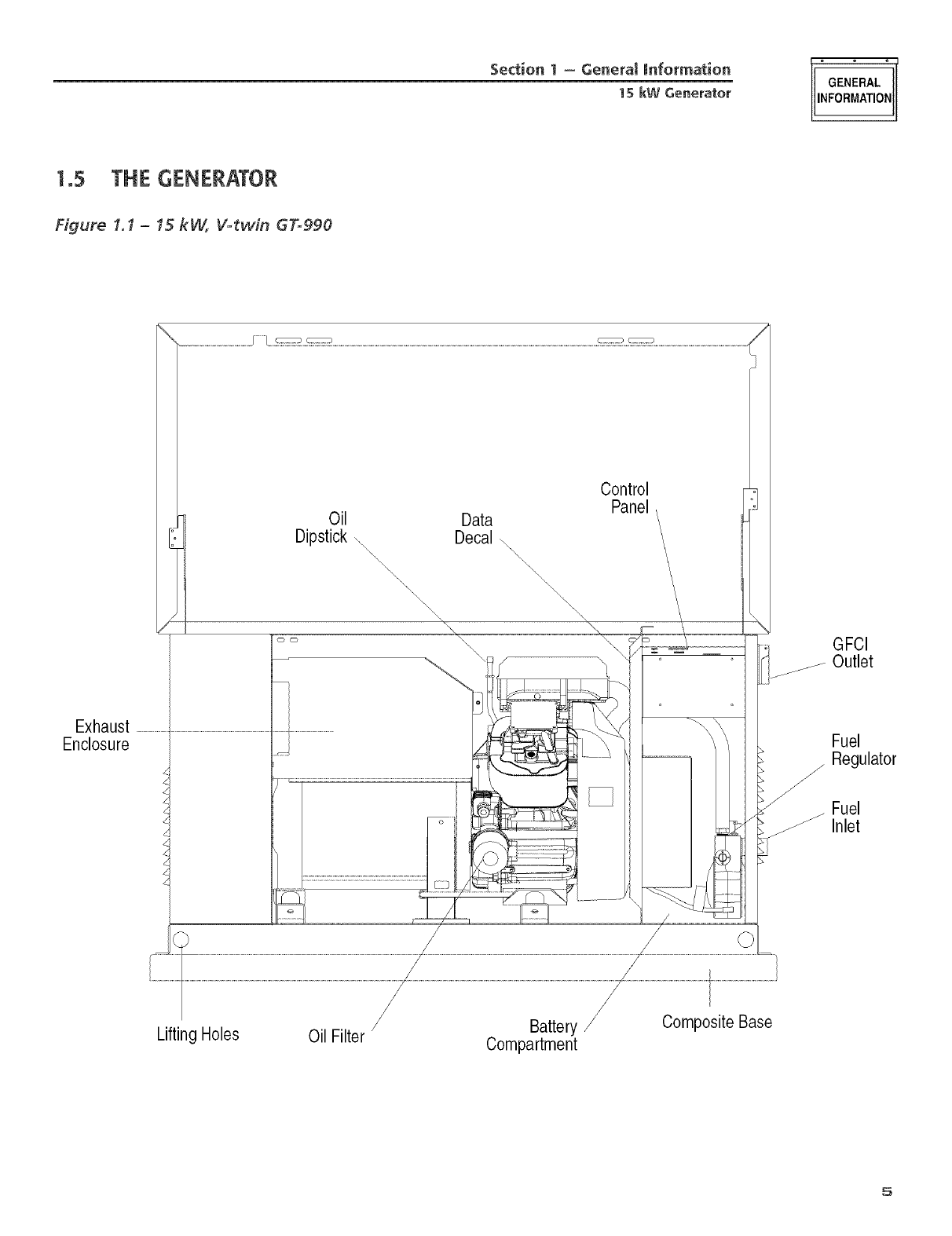
1°5 THE GENERATOR
Figure 1.1 -15 kW, V-twin 67"=990
Exhaust
Enclosure
Oil Data
Dipstick \ Decal \
\\\ \\\
\\\ \\
\\\\\
\\\\\\\ \
\\
\
_r.
Control
Panel
GFCI
_ Outlet
Fuel
/Regulator
Fuel
Inlet
LiftingHoles Oil Filter Battery
Compartment
CompositeBase
5
"GENERAL°
NFORMATON
Section 1 - General information
1S kW Generator
1.6
1.6.1 GENERATOR
Rated Maw Cont Power Capacity (Watts _) ..... 13,000 NG/
15,000 LP+
Rated Voltage ....................................................... 120/240
Rated Max. Conthmous Load Current (Amps)
120 Volts + ...................................... 108.3 NG/125_0 LP
240 VoRs ............................................ 54.2 NG/62.5 LP
Main Line Circuit Breaker .................................... 65 Atnp
Phase ............................................................................. 1
Nmnber of Rotor Poles ................................................... 2
Rated AC Frequency ................................................ 60 Hz
Power Factor .................................................................. 1
Recommended Air Filter ........................... Part # 0C8127
Battery Requirement at
-17.8" C (0" F) ....................... Group 26/26R 12 Volts and
525 Cold<ranking Amperes Mhlhnmn
Weight ........................................................... 487 Pounds
Output Sound Level (_ 23 ft (7m)
at fldl load ................................................... 71.5 db (A}
Normal Operating Ran,_e ........................... -20°F (-28.8"C)
to 104°E 140"C)
* Maxiiyll/ill w_th_e aIld (;llrreza are Slit)jeer to _ti]d lhl]ited by Slid] l'z_<:tOrS
as fuel Btu (;oIlteIlt, aI]]l)ieI][ teI]]l)eratllre, altitllde, eI]_hle power alld COn-
ditiom etc. Maximum power decreases about 3.5 percent fl_r each lnOO
feet above sea level: and also will deele_se about 1 pereenl for each 6 '_ ¢
(IfYF)abovei(¢_( (60_F).
+ Total current i_l hvo separate circuits. Current in each circuit must not
exceed the value staledh>r 240V
1.6.2 ENGINE
Type of Engine ...................................................... GT-990
Nmnber of Cylinders ...................................................... 2
Rated Horsepower .................................. 30 %3,¢;00 rpm
Displacement .......................................................... 992ec
Cylinder Block ..................... Alumimmi w/Cast Iron Sleeve
_&dve Arrangement .................................. Overhead Valves
Ignition System .............................. Solid-state w/Magneto
Reeonimended Spark Plug ................................... 0D4529
Spark Plug Gap ............................ 0.508 mm (0.020 inch)
Compression Ratio ................................................... 9.5:1
Starter .................................................................... 12Vdc
Oil Capacity Including Filter .................... Approx. 1.7 Qts
Recommended Oil Filter ........................... Part # 070185
Recommended Air Filter ........................... Part # 0C8127
Operating RPM ........................................................ 3,600
1o7 FUEL REQUIREMENTS
AND RECOMMENDATIONS
With LP gas, use only the vapor withdrawal sys-
tem. Tllis type of system uses the vapors %treed
above tile liquid lilel in tile storage tank.
The engine has been fitted witll a fllel earburetion
system that meets tile specifications of the 1997
California Air Resources Board for tamper=proof
dual fllel systems. The unit will run on natural gas or
LP gas, but it has been factory set to run on natural
gas. Should tile primary ihel need to be changed to
LP gas, the fllel system needs to be reeonfigured. See
instructions in the "Reeonfiguring the iSlel Systenf'
seetion.
Recommended fuels should lmve a Btu content of at
least 1,000 Btus per cubic loot for natural gas; or at
least 2,520 Btus per cubic toot lot LP gas. Ask the
fllel supplier for tile Btu content of the thee
Required fllel pressure for natural gas is 5 inches
to 7 inches water column (0.18 to 0.25 psi); and
for liquid propane, 11 inches to 14 inches of water
column (0.4 to 0.5 psi).
NOTE:
Any piping used to connect the generator to the
fuel supply should be of adequate size to ensure
the fuel pressure NEVER drops below 4 inches
water column for natural gas or 10 inches water
column for liquid propane for all load ranges.
1o8 FUEL CONSUMPTION
Model # Nat. Gas {*} LP Vapor {**}
1/2 Load Full Load 1/2 Load Full Load
05207 156 220 1.58/58 2,40/88
* Nalmal _as is in cubic feet per hour.
** LP is in gallons per hour/cubi( feet per hour.
** _ Values _ivell al-e at)t)l OXillla(e.
Gaseous fuels such as natural gas and liquid
propane (LP) gas are highly explosive. Even the
slightest spark can ignite such fuels and cause
an explosion. No leakage of fuel is permitted.
NaturM gas, which is lighter than air, tends to
collect in high areas. LP gas is heavier than air
and tends to settle in low areas.
6
Section I - General Information
1SkW Generator GENERAL
NFORIVlATON
1.9 RECONNGURING THE
FUEL SYSTEM
109.1 15KW, 990CC ENGINES
To reeonligure tile fuel system lrom NO to LR
these steps: NOTE:
follow
The primary regulator for the propane supply is
NOT INCLUDED with the generator. A fuel pres-
sure of 11 to 14 inehes of water column (0.4 to
0.5 psi) to the fuel inlet of the generator MUST
BE SUPPLIED.
1. Turn off tile gas supply. (if connected)
2. Open the roof and remove the door.
3. Remove the battery. (if installed)
4. Remove the engine air in baffle located on the left-
hand side of the battery compartment. _[\vo M6
screws are located on top of the bane and two
M6 screws are located on the inside of the baNe
towards the back.
5. Remove the small hose clamp and hose from the
filel regulator. It may be necessary to pry the hose
off of the brass fitting using a screwdriver to gen-
tly lilt up the hose edge.
(3. Remove the small brass hose fitting from the
regulator casting.
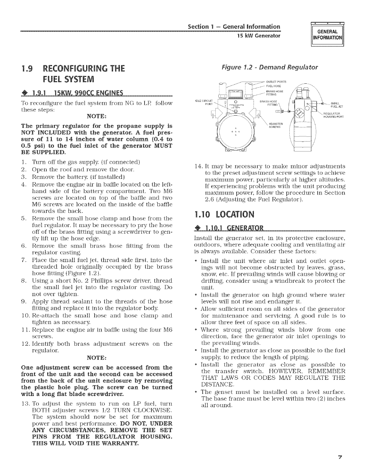
7. Place the small fitel jet, thread side first, into the
threaded hole originally occupied by the brass
hose fitting (Figure 1.2).
8. Using a short No. 2 Phillips screw driver, thread
the small fuel jet into the regulator casting. Do
not over tighten.
9. Apply thread sealant to the threads of the hose
fitting and replace it into the regulator body.
10. Re-attach the small hose and hose clamp and
tighten as necessary.
1 1. Replace the engine air in baNe using the ibur M6
screws.
12. Identify both brass adjustment screws on the
regulator. NOTE:
One adjustment screw can be accessed from the
front of the unit and the second can be accessed
from the back of the unit enclosure by removing
the plastic hole plug. The screw can be turned
with a long fiat blade screwdriver.
13. To adjust the system to run on LP fuel, turn
BOTH adjuster screws 1/2 TURN CLOCKWISE.
The system should now be set ibr maximmn
power and best performance. DO NOT, UNDER
ANY CIRCUMSTANCES, REMOVE THE SET
PINS FROM THE REGULATOR HOUSING.
THIS WILL VOID THE WARRANTY.
Figure 1.2 -Demand Regulator
}
IDLE OIROUIT
PORT _. 0
FUEL JET
"_ REGULATOR
HOUSING SORT
14. It may be necessary to make minor adjustments
to the preset adjustment screw settings to achieve
maximum power, particularly at higher altitudes.
If experiencing problems with the unit producing
maximmn power, follow the procedure in Section
2.6 (Adjusting the ]_51elRegulator).
1.10
ENERAT0
Install the generator set, in its protective enclosure,
outdoors, where adequate cooling and ventilating air
is always available. Consider these factors:
e
e
e
e
Install the unit where air inlet and outlet open-
ings will not become obstructed by leaves, grass,
snow, etc. If prevailing winds will cause blowing or
driiling, consider using a windbreak to protect the
unit.
Install the generator on high ground where water
levels will not rise and endanger it.
Allow sufficient room on all sides of the generator
for maintenance and servicing. A good rule is to
allow three feet of space on all sides.
Where strong prevailing winds blow from one
direction, face the generator air inlet openings to
the prevailing winds.
Install the generator as close as possible to the fllel
supply, to reduce the length of piping.
Install the generator as close as possible to
the transfer switch. HOWEVER, REMEMBER
THAT LAWS OR CODES MAY REGULATE THE
DISTANCE.
The genset must be installed on a level surface.
The base frame nmst be level within two (2) inches
all around.
7
Section 1 - Genera[ Information
GENERAL
INFORMATION 15 kW Generator
1=103=1 15 kW Units
Transfer switches for use with this generator are sold
separately and can be purchased from dealers.
o Install any transter switch in accordance with the
instructions supplied with the transfer switch.
o Failure to utilize a the manufacturer's transfer
switch with this generator will void the warranty,
1ol 1 BATTERY[NSTALLATIGN
Fill the battery with the proper electrolyte fluid if
necessary and have the battery fully charged betbre
installing it.
Beibre installing and connecting the battery, complete
the iollowing steps:
1. Set the generator's ALJTO/OFF/NLa_NUAL switch to
OFE
2. _fffu-n off utility power supply to the transfer
switch.
3. Remove the 7.5 amp and 15 amp Iilses Kom the
generator control panel.
Battery cables were iaetory connected at the genera-
tor (Figure 1.3). Connect cables to battery posts as
Ihllows:
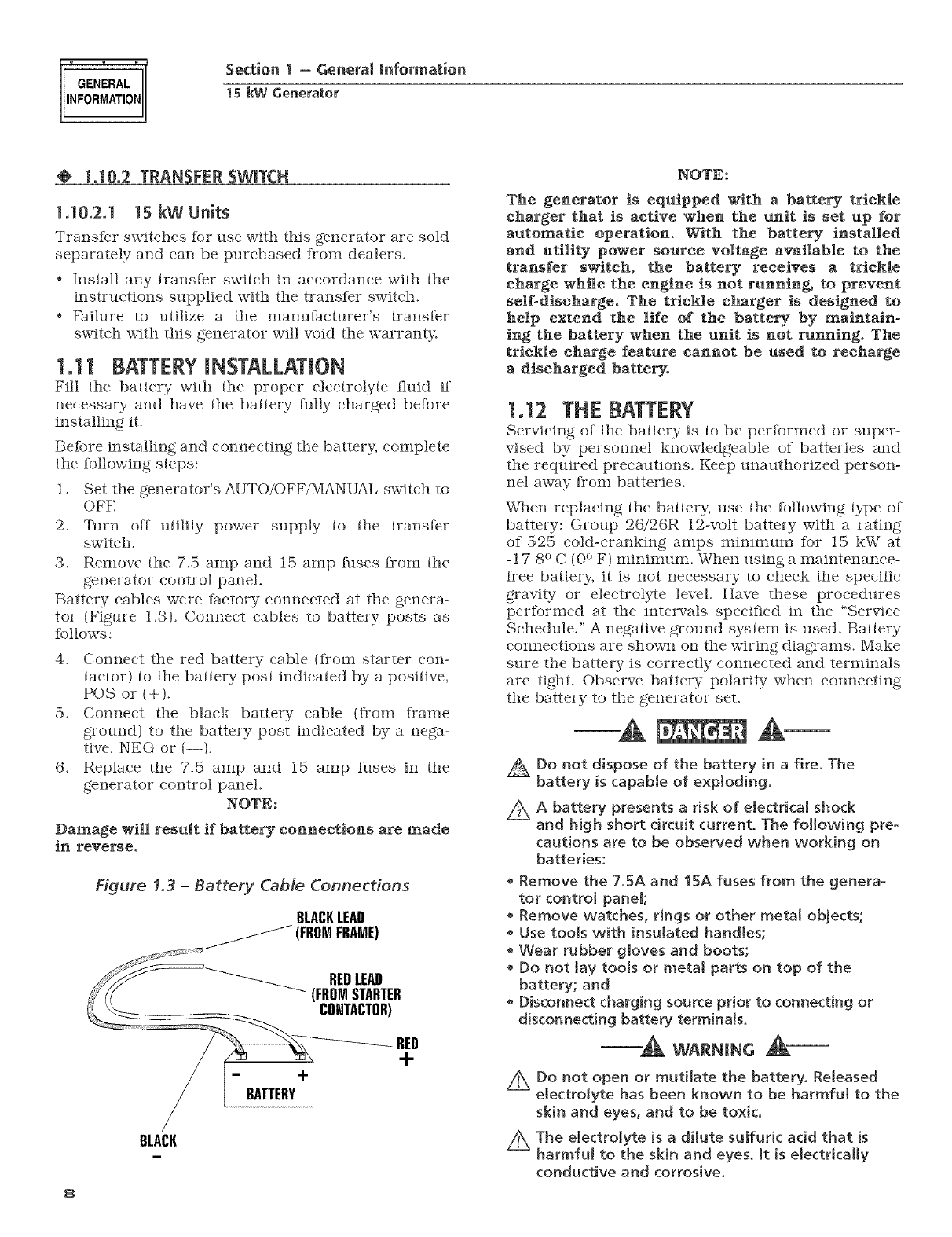
4. Connect the red battery cable (from starter con-
tactor) to the battery post indicated by a positive,
POS or (+).
5. Connect the black battery cable {IYom frame
ground) to the battery post indicated by a nega-
tive, NEG or (--).
6. Replace the 7.5 amp and 15 amp fuses in the
generator control panel.
NOTE:
Damage will result if battery connections are made
in reverse.
Figure 1.3 -Battery Cable Connections
BLACKLEAD
FROMFRAME)
--.I-
BATTERY
BEDLEAD
(FROMSTARTER
COHTACTOR)
-RED
+
BLACK
8
NOTE:
The generator is equipped with a battery trickle
charger that is active when the unit is set up for
automatic operation. With the battery installed
and utility power source voltage available to the
transfer switch, the battery receives a trickle
charge while the engine is not running, to prevent
self-discharge. The trickle charger is designed to
help extend the life of the battery by maintain-
ing the battery when the unit is not running. The
trickle charge feature cannot be used to recharge
a discharged battery.
1.12 THE BATTERY
Servicing of the battery is to be performed or super-
vised by personnel knowledgeable of batteries and
the required precautions. Keep unauthorized person-
ne] away Kom batteries.
%_]e]] replacing the battery; use the following type of
battery: Group 2G/26R 12-volt battery with a rating
of 525 coldocranking amps mininmm Ibr 15 kW at
-17.8 ° C (0 ° F) minimun]. When using a maintenance_
I]*ee battery, it is not necessary to cheek the specific
gravity or electrolyte level. Have these procedures
pertormed at the intervals specified in the "Service
Schedule)' A negative ground system is used. Battery
connections are shown on the wiring diagrams. Make
sure the battery is correctly connected and terminals
are tight. Observe battery polarity ° when connecting
the battery to the generator seL
Do not dispose of the battery in a fire. The
battery is capabJe of expIodingo
Z_ A battery presents a risk of electrica[ shock
and high short circuit current. The following pre-
cautions are to be observed when working on
batteries:
• Remove the 7.5A and 15A fuses from the genera-
tor contro] panel;
• Remove watches, rings or other metal objects;
• Use tools with insulated handles;
• Wear rubber gloves and boots;
• Do not lay tools or metaJ parts on top of the
battery; and
• Disconnect charging source prior to connecting or
disconnecting battery terminaJs.
-A wAH.c A-
/_ Do not open or mutilate the battery. ReJeased
electrolyte has been known to be harmfut to the
skin and eyes, and to be toxic.
Z_ The electrolyte is a dilute suJfur[c acid that is
harmful to the skin and eyes. it is electrically
conductive and corrosive.
Section 1 - Post InstMIation Start-up and Adiustments
1SkW Generator
POS%@
iNSTALLATiON
STAR%UP
ADJUSTMENTS
The following procedures are to be observed:
• Wear full eye protection and protective clothing;
• Where eJectrolyte contacts the skin, wash it off
immediately with water;
• Where eJectro[yte contacts the eyes, immediately
flush thorougNy with water and seek medical
attention; and
• Spilled electrolyte is to be washed down with an
acid neutrMizing agent. A common practice is to
use a solution of ! pound (500 grams) bicarbonate
of soda to 1 galIon (4 liters) or water. The bicar-
bonate of soda soJution is to be added untit the
evidence of reaction (foaming) has ceased. The
resulting liquid is to be flushed with water and the
area dried.
Z_ Lead-acid batteries present a risk of fire because
they generate hydrogen gas. The
following procedures are to be followed:
DO NOT SMOKE when near the battery;
DO NOT cause flame or spark in battery area; and
• Discharge static electricity from body before touch-
ing the battery by first touching a grounded metal
surface.
Z_ Be sure the AUTO/OFF/MANUAL switch is set to
the OFF position before connecting the battery
caMes. Jf the switch is set to AUTO or MANUAL,
the generator can crank and start as soon as the
battery cables are connected.
Be sure the utility power supply is turned off, or
sparking may occur at the battery posts as the
cables are attached and cause an explosion.
2.1 BEFOREINITIAL START-UP
Betbre starting, complete the following:
i. Set the generator's main circuit breaker to its
OFF (or open) position.
2. Set the generator's AUTO/OFF/MANUAL switcil to
the OFF position.
3. Turn OFF the utility power supply to the transfer
switcil using the means provided (such as the
utility main line circuit breaker).
4. Check tile engine crankcase oil level and, if neces-
sary, till to tile dipstick FULL mark witil the rec-
ommended oil. Do not fill above the FULL mark.
5. Cileck the file] supply. Gaseous fuel lines must
imve been properly purged and leak tested in
accordance witil applicable fuel-gas codes. All
file] simtoff valves in tile I_lel supply lines must
be open.
"_ CAUTION
z_ Never operate the engine with the oil level
below the "Add" mark on the dipstick. Doing
this could damage the engine.
2.2 CHECK TRANSFER SWITCH
Reter to Section 3.5, of tile owner's manual lbr man-
ual operation procedures.
A Ak-
Z_ Do not attempt manual transfer switch opera-
tion until aH power voltage supplies to the
transfer switch have been positively turned off.
Failure to turn off all power voltage supplies
will result in extremely hazardous and possibIy
fatat electrical shock.
2.3 ELECTRICAL CHECKS
Complete electrical checks as follows:
1. Set tile generator's main circuit breaker to its
OFF (or open} position.
2. Set the generator's AUTO/OFF/MANUAL switcil to
the OFF position.
3. Turn OFF the utility power supply to tile transfer
switcil using tile means provided (sucil as the
utility main line circuit breaker).
4. _[hlrn on tile utility power supply to the transfer
switcil using the means provided (sucil as a utility
main line circuit breaker).
AxThe transfer switch is now electrically "hot."
Contact with "hot" parts will result in extremely
hazardous and possibly fatal electrical shock.
Proceed with caution.
5. Use an accurate AC voltmeter to check utility
power source voltage across terminals N1 and
N2. Nominal line-toqine voltage should be 240
volts AC.
G. Check utility power source voltage across termi-
nals N1 and the transfer switch neutral lug; then
across terminal N2 and neutral. Nominal line-to-
neutral voltage silould be 120 volts AC.
7. Wilen certain that utility supply voltage is compat-
ible with transfer switch and load circuit ratings,
tm-n OFF the utility power supply to the transfer
switcil.
8. Set tile generator's main circuit breaker to its
OFF (or open) position. Initial tests will be con-
ducted at no-load condition.
9. On tile generator panel, set tile AUTO/OFF/
MANUAL switch to MANUAL. The engine should
crank and start.
10. Let the engine warm up for about five minutes to
allow internal temperatures to stabilize. Then, set
the generator's main circuit breaker to its ON (or
closed) position.
9
iNSTALLATiON
START-UP
ADJUSTMENTS
Section 2 - Post Installation Start-up and Adiustments
1S kW Generator
Z_ Proceed with caution! Generator power voltage
Jsnow supplied to the transfer switch, Contact
with live transfer switch parts will result in dan-
gerous and possibly fatal electrkal shock,
11. Connect an accurate AC voltmeter and a fre-
quency meter across transfer switch terminal
lugs E 1 and E2. Voltage should be 242-252 volts;
Kequency should read about 61-63 Hertz.
12. Connect the AC voltmeter test leads across ter-
minal lug E1 and neutral; then across E2 and
neutral. In both cases, voltage reading should be
121-126 volts AC.
13. Set the generator's main circuit breaker to its
OFF (or open) position. Let the engine run at no-
load tot a few minutes to stabilize internal engine
generator temperatures.
14. Set the generator's AUTO/OFF/MANUAL swifeh to
OFE The engine should shut down.
NOTE:
it is important not to proceed until certain that
generator AC voltage and frequency are correct
and within the stated limits. Oenerally_ if both AC
frequency and voltage are high or lo_; the engine
governor requires adjustment. If frequency is cor-
rect, but voltage is high or low, the generator's
voltage regulator requires adjustment.
2.4 GENERATOR TESTS UNDER LOAD
To test the generator set with electrical loads applied,
proceed as follows:
1. Set generator's main circuit breaker to its OFF
(or open) position.
2. Set the generator's AUTO/OFF/MANUAL
switch to OFE
3. Turn OFF the utility power supply to the transfer
swifeh, using the means provided {such as a util-
ity main line circuit breaker).
wA.NINc
Z_ Do not attempt manual transfer switch opera-
tion until aH power voltage supplies to the
transfer switch have been positiveJy turned off.
Failure to turn off aH power vottage supplies
will result in extremely hazardous and possibly
fatal electrical shock,
4. Manually set the transfer swifeh to the STANDBY
position, i.e., load terminals connected to the
generator's E 1/E2 terminals. The transfer switch
operating lever should be down.
5. Set the generator's AUTO/OFF/iVlANUAL switch
to MANUAL. The engine should crank and start
irmnediatel_t
lo
G. Let the engine stabilize and warm tip for a few
minutes.
7. Set the generator's main circuit breaker to its ON
(or closed) position. Loads are now powered by
the standby generator.
8. Turn ON electrical loads. Apply an electrical load
equal to the fllll rated wattage/amperage capacity
of the installed generator.
9. Connect an accurate AC voltmeter and a frequen-
cy meter across terminal lugs E 1 and E2. Voltage
should be greater than 230 volts; frequency
should be greater than 58 Hertz.
10. Let the generator run at full rated load tot 20-30
minutes. Listen for unusual noises, vibration or
other indications of abnormal operation. Check
ibr oil leaks, evidence of overheating, etc.
11. When testing tinder load is complete, turn OFF
electrical loads.
12. Set the generator's nmin circuit breakers to their
OFF (or open) positions.
13. Let the engine run at no-load %r a few minutes.
14. Set the AUTO/OFF/MANUAL switch to OFE The
engine should shut down.
2.5 CHECKINGAUTOMATIC
OPERATmON
To check the system for proper automatic operation,
proceed as follows:
1. Set the generator's main circuit breaker to it's
OFF (or open) position.
2. Check that the AUTO/OFF/MANUAL switch is set
to OFE
3. Turn OFF the utilitypower supply to the transfer
switch using the means provided (such as a utility
main line circuit breaker).
4. Manually set the transfer switch to the UTILITY
position, i.e., load terminals connected to the util-
ity power source side.
5. 7him ON the utility power supply to the transfer
swifeh, using the means provided {such as a util-
ity mata line circuit breaker).
G. Set the AUTO/OFF/MANUAL switch to AUTO.
Then set the generator's mata circuit breaker to
its ON (or closed) position. The system is now
ready for autonmtic operation.
7. Turn OFF the utility power supply to the transfer
swifeh.
With the AUTO/OFF/MANUAL swifeh at AUTO, the
engtae should crank and start when the utility source
power is turned OFE AAer starting, the transfer
swifeh should connect load circuits to the standby
side. Let the system go through its entire automatic
sequence of operation.
Section 2 - Post Installation Start-up and Adjustments
15 kW Generator
POS_@
iNSTALLATiON
STAR.UP
ADJUSTMENTS
With the generator running and loads powered by
generator AC output, turn ON tile utility power supply
to the transfer switch. Tile ibllowing should occur:
.Alter about six seconds, the switch should transler
loads back to tile utility power source.
.About one minute after retransfer, tile engine
should shut down.
2.5 ADJUSTING THE REGULATOR
{NATURAL(;AS ONLY}
Although the generator has been Nctory set to pro-
vide rnaxirnum powen it may be necessary in some
areas to a(_just this setting. Because natural gas has
difthrent BTU or power content across tile country
the engine may not per%rm as designed.
If experiencing engine problerns at high or flfll load
conditions %llow these steps, it will require a tre-
queney meter to per%tin this procedure.
1. Turn off utility power to tile main distribution
panel in the house. This earl be done by switching
tile service main breaker to tile off or open posi-
tion.
2, Allow the generator to start beIbre loading tile
generator. Confirm tile no-load fl-equency with
the roof open and door off is set at 63-63.5 Hz.
Transfer load to emergency circuits.
3. Turn on appliances, lights, pumps, etc., that are
on the emergency circuits in an attempt to fully
load the generator. Be cautious not to overload
the generator. Use tile tallowing chart as a guide:
U_it [ 120 Volts | 240 Volts
15 kW I 108.3 amps I 54.2 anlps
4. When lhll load has been achieved. Connect a lYe-
queney meter to the output lugs of tile generator's
main line circuit breaker.
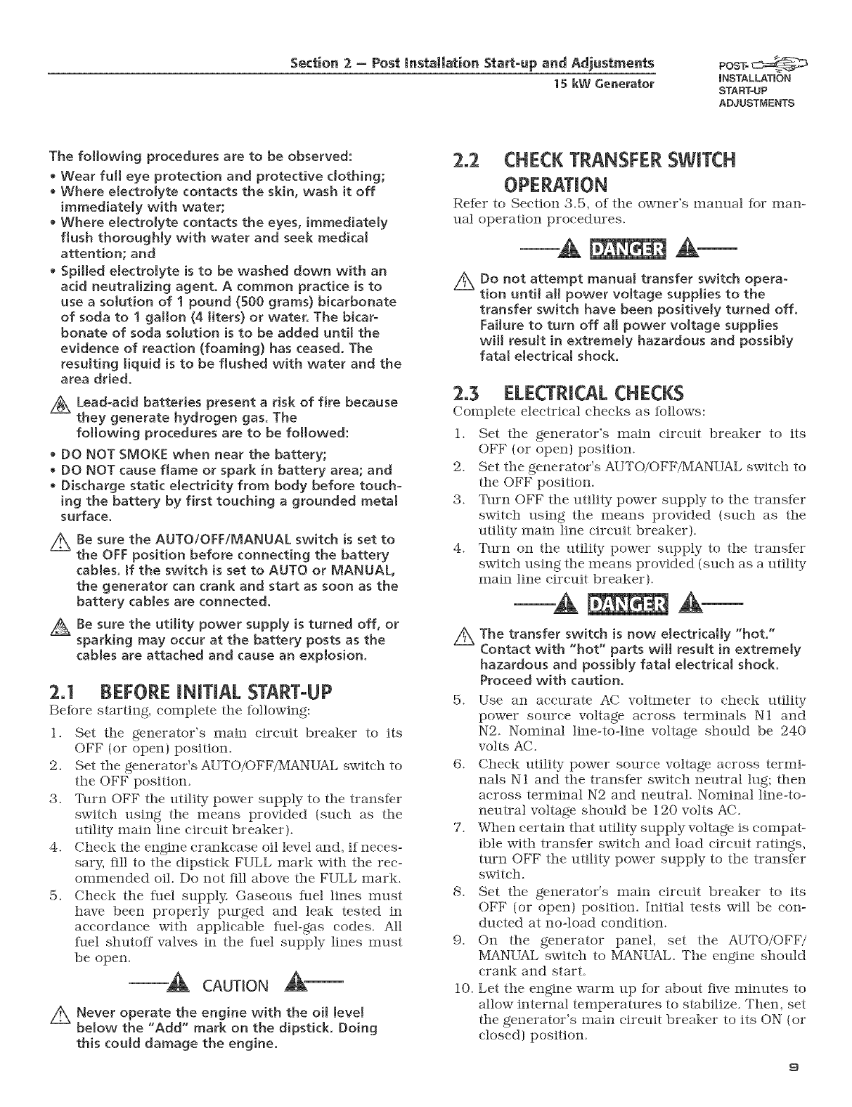
5. Tile i_lel regulator is fitted with two adjustment
screws. While watching tile Kequency meter,
slowly turn the adjustment screw clockwise or
counterclockwise one at a time until highest Ke-
queney is read on the meter. Only limited adjust-
ment is available between the set pins. Under no
circumstances should any of tile pins be removed
(Figures 2.1 and 2.2).
Figure 2.1 -- Dual Fuel Regulators
V-twin 410
Adjustment
(BothSides}
(Beth Sides)
Adjustment
Screw
(OneSide
Only}
Pin
6. When the highest lrequeney is reached maximum
power has been set. Then turn both adjustment
screws 1/4 turn counterclockwise. Regulator is
now set.
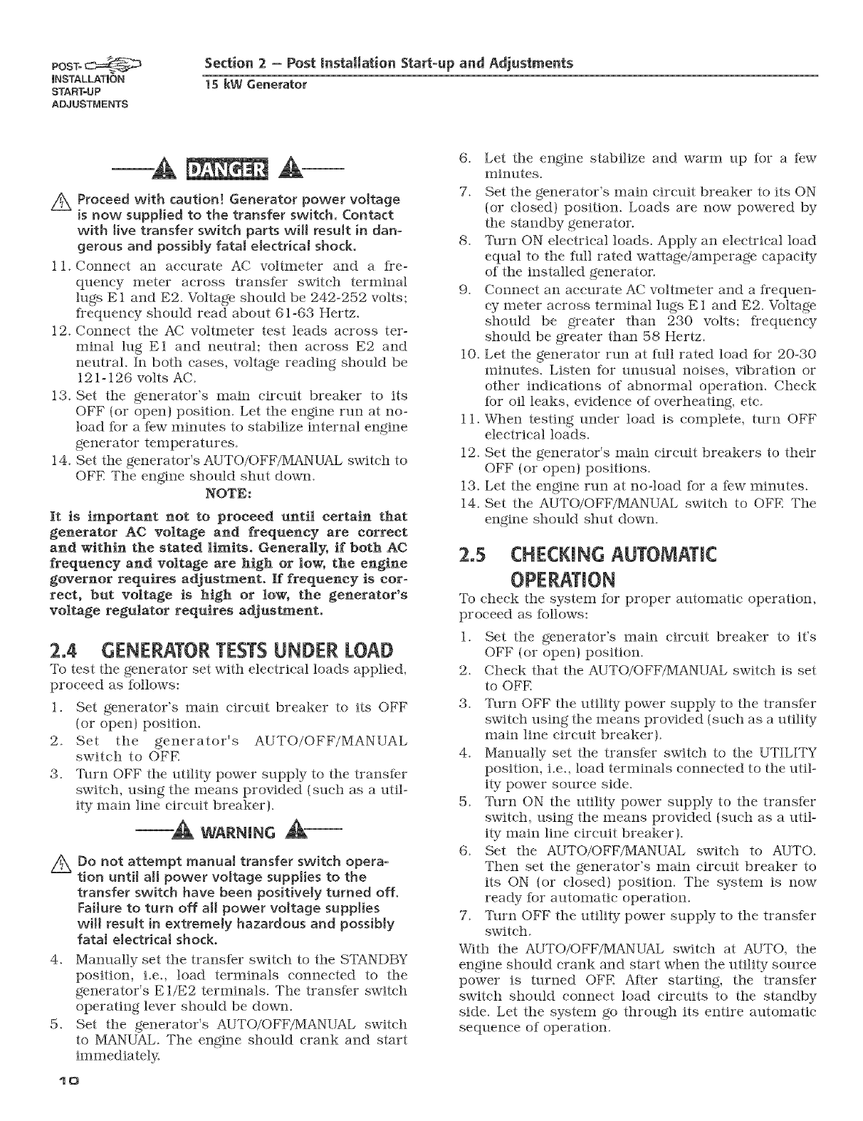
Figure 2.2 -- Placement of Regulator
7_ _[?lrn utility power to the main distribution panel
back on. This can be done by switching tile ser-
vice main breaker to the on or closed position.
Allow tile generator to shut down.
wARNINc
Z_ Do not make any unnecessary adjustments.
Factory settings are correct for most applica-
tions. However, when making adjustments, be
careful to avoid overspeeding the engine.
If this procedure or equipment are not awlilable,
locate the nearest Dealer and they earl perform tile
adjustments.
NOTE:
A service fee may be charged for this adjustment.
11
OPERATION Section 3- Operation
IS kW Generator
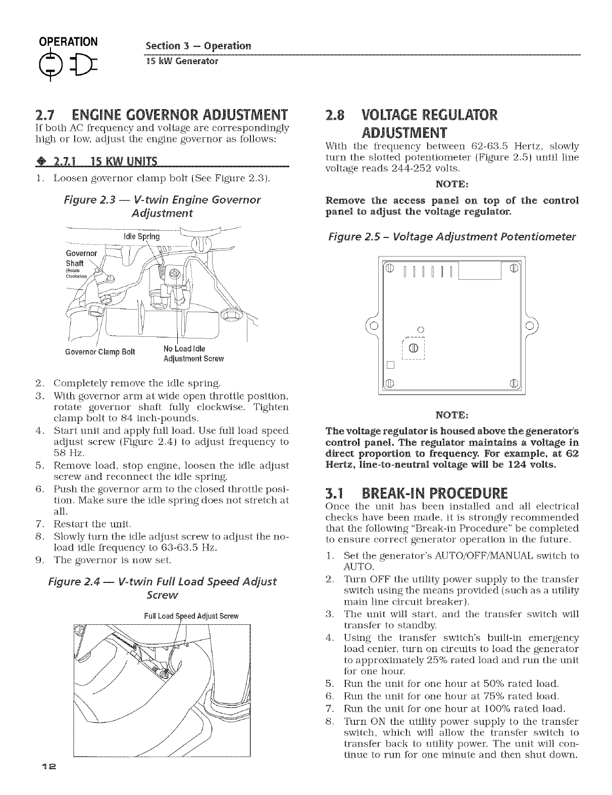
2°7 ENGINE GOVERNORADJUSTMENT
If both AC l_-equeney and voltage are eorrespondtagly
high or low, adjust tile engine governor as follows:
2.7,1 15 KW UMTS
1. Loosen governor clamp bolt (See Figure 2.3).
Figure 2,3 -- V-twin Engine Governor
Adjustment
Gevemor Clamp £Nt
2. Completely remove the idle spring.
3. With governor arm at wide open throttle position,
rotate governor shaft ikflly clockwise. Tighten
clamp bolt to 84 taeh-pounds.
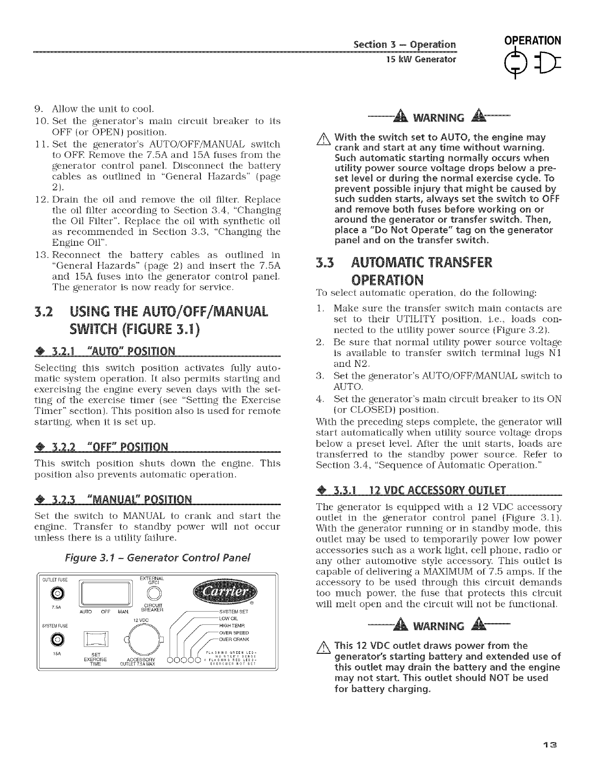
4. Start unit and apply frill load. Use full load speed
adjust screw {Figure 2.4) to adjust frequency to
58 Hz.
5. Remove load, stop engtae, loosen the idle adjust
screw and reconnect the idle sprtag.
(3. Push the governor arm to the closed throttle posi-
tion. Make sure the idle spring does not stretch at
all.
7. Restart the unit.
8. Slowly turn the idle adjust screw to adjust the no-
load idle fi-equeney to 63-63.5 Hz.
9. The governor is now set.
Figure 2,4 -- V-twin Fuff Load Speed Adjust
Screw
12
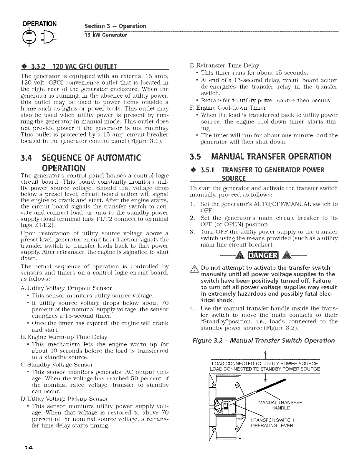
2.8 VOLTAGEREGULATOR
With the Irequeney between 62-63.5 Hertz, slowly
turn the slotted potentiometer (Figure 2.5) until line
voltage reads 244-252 volts.
NOTE:
Remove the access panel on top of the control
panel to adjust the voltage regulator.
Figure 2.5 -Voltage A djustmen t Po ten tiometer
HHHHHHI
[]
o
_©'
i
L
NOTE:
The voltage reg_ator is housed above the generator's
control panel. The regulator maintains a voltage in
direct proportion to frequency. For example, at 62
Hertz, line-to-neutral voltage will be 124 volts.
3.1 BREAK4N PROCEDURE
Once the unit has been tastalfed and all electrical
cheeks have been made, it is strongly recommended
that the followtag "Break-ta Procedure" be completed
to ensure correct generator operation ta the future.
1. Set the generator's AUTO/OFF/MANUAL switch to
AUTO.
2. Turn OFF the utility power supply to the transfer
switch ustag the means provided (such as a utility
mata ltae circuit breaker).
3. The unit will start, and the transfer switch will
transfer to standby.
4. Ustag the transfer swifeifs built-ta emergency
load center, mrn on circuits to load the generator
to approximately 25% rated load and run the unit
%r one hour.
5. Run the unit for one hour at 50% rated load.
6. Run the unit for one hour at 75% rated load.
7. Run the unit for one hour at 100% rated load.
8. _[_lrn ON the utility power supply to the transfer
switch, which will allow the transfer switch to
transfer back to utility powen The unit will con-
tinue to run for one mtaute and then shut down.
Section 3 - Operation
15 kW Generator
OPERATION
9. Allow tile unit to cool.
10. Set the generator's main circuit breaker to its
OFF (or OPEN) position.
1 1. Set the generator's AUTO/OFF/MANUAL swifeh
to OFE Remove the 7.5A and 15A Iilses Irom the
generator control panel. Disconnect the battery
cables as outlined in "General Hazards" {page
2).
12. Drain tile oil and remove the oil tilter. Replace
the oil iilter according to Section 3.4, "Changing
the Oil Filter". Replace the oil with s_lthetic oil
as reconunended in Section 3.3, "Changing the
Engine Oil".
13. Reconnect the battery cables as outlined in
"General Hazards" {page 2) and insert the 7.5A
and 15A fllses into the generator control panel.
The generator is now ready for service.
3.2 USINGTHEAUm/OFF/MANUAL
SWITCH(FIGURE3J)
3o2ol "AUTO" POSITION
Selecting this switch position activates t_llly auto-
matic system operation. It also permits starting and
exercising the engine every seven days with the set-
ting of the exercise timer (see "Setting the Exercise
Timer" section). This position also is used thr remote
starting, when it is set up.
¢' 3,2,2 "OFF" POSITION
This switch position shuts down the engine. This
position also prevents automatic operation.
3,2,3 "MANUAL" POSITION
Set the switch to MANUAL to crank and start the
engine. Transfer to standby power will not occur
unless there is a utility failure.
Figure 3.1 -Generator Contro! Panel
OUTLETFUSE
?; AUTO OFF
SYSTEM FUSE
15A SET
EXERCISE
TIME
EXTERNAL
GFCJ
©
CIRCUIT
MAN BREAKER _SYSTEM SET
12VDC /" _LOW OIL
HIGH TEMR
OVER CRANK
ACCESSORY ..... RHclNa_ RREND0 _ED _T
-_ WARNING _-
2xWith the switch set to AUTO, the engine may
crank and start at any time without warning.
Such automatic starting normally occurs when
utility power source voltage drops bMow a pre-
set level or during the normal exercise cycle. To
prevent possible injury that might be caused by
such sudden starts, always set the switch to OFF
and remove both fuses before working on or
around the generator or transfer switch. Then,
place a "Do Not Operate" tag on the generator
panel and on the transfer switch.
3.3 AUTOMATIC TRANSFER
To select automatic operation, do the following:
1. Make sure the transfer switch main contacts are
set to their UTILITY position, i.e., loads con-
nected to the utility power source (Figure 3.2).
2. Be sure that normal utility power source voltage
is available to transfer switch terminal lugs N1
and N2.
3. Set the generator's A2UTO/OFF/MANUAL switch to
AUTO.
4. Set the generator's main circuit breaker to its ON
(or CLOSED) position.
With the preceding steps complete, the generator will
start automatically when utility source voltage drops
below a preset level. After the unit starts, loads are
transferred to the standby power source. Refer to
Section 3.4, "Sequence of Automatic Operation."
@3,3,1 12 VDC ACCESSORYOUTLET
The generator is equipped with a 12 VDC accessory
outlet in the generator control panel {Figure 3.1).
With the generator running or in standby mode, this
outlet may be used to temporarily power low power
accessories such as a work ligM, cell phone, radio or
any other automotive style accessory. This outlet is
capable of delivering a MAXIMUM of 7.5 amps. If the
accessory to be used through this circuit demands
too nmch power, the fuse that protects this circuit
will melt open and the circuit will not be flmctional.
-_ WARNING _-
Z_ This 12 VDC outlet draws power from the
generator's starting battery and extended use of
this outlet may drain the battery and the engine
may not start. This outlet should NOT be used
for battery charging.
13
OPERATION Section 3 - Operation
1S kW Generator
Tile generator is equipped with an external 15 amp,
120 volt, GFCI convenience outlet that is located in
tile right rear of the generator enclosure. _rhen tile
generator is running, in the absence of utility power,
this outlet may be used to power items outside a
home such as lights or power tools. This outlet may
also be used when utility power is present by run-
ning the generator in manual mode. This outlet does
not provide power if the generator is not running.
This outlet is protected by a 15 amp circuit breaker
located in the generator control panel {Figure 3.1 ).
3.4 SEQUENCEOF AUTOMATIC
OPERATION
The generator's control panel houses a control logie
circuit board. This board constantly monitors util-
ity power source voltage. Should that voltage drop
below a preset level, circuit board action will signal
the engine to crank and start. After the engine starts,
the circuit board signals the transfer switch to acti-
vate and connect load circuits to the standby power
supply (load terminal lugs T l/T2 connect to terminal
lugs E l/E2).
Upon restoration of utility source voltage above a
preset level, generator circuit board action signals the
transter switch to transfer loads back to that power
supply. After retranster, the engine is signalled to shut
down.
The actual sequence of operation is controlled by
sensors anti timers on a control logic circuit board,
as follows:
A. Utility Voltage Dropout Sensor
.This sensor monitors utility source voltage.
* If utility source voltage drops below about 70
percent of the nominal supply voltage, the sensor
energizes a 15-second timer.
° Once the timer has expired, the engine will crank
and start.
B. Engine Warm-up Time Delay
° This mechanism lets the engine warm tip for
about 10 seconds before the load is transferred
to a standby source.
C. Standby Voltage Sensor
* This sensor monitors generator AC output volt-
age. When the voltage has reached 50 percent of
the nominal rated voltage, transfer to standby
ear occur.
D. Utility Voltage Pickup Sensor
* This sensor monitors utility power supply volt-
age. When that voltage is restored to above 70
percent of the nominal source voltage, a retrans-
ter time delay starts timing.
14
E.Retransfer Time Delay
. This timer runs for about 15 seconds.
° At end of a 15-second delay, circuit board action
de-energizes the transfer relay in the transfer
switch.
° Retransfer to utility power source then occurs.
E Engine Cool-down Timer
° When the load is transferred back to utility power
source, the engine cool-down timer starts tin>
ing.
° The timer will run for about one minute, and the
generator will then shut down.
3.5 MANUAt.TRANSFEROPERATION
@3.5.1 TRANSFERTO GENERATORPOWER
To start the generator and activate the transfer switch
manually, proceed as lbllows:
1. Set the generator's AUTO/OFF/1VLA_NUAL switch to
OFE
2. Set the generator's main circuit breaker to its
OFF (or OPEN) position.
3. %lrn OFF the utility power supply to the transfer
switch using the means provided {such as a utility
main line circuit breaker).
A
4_
Do not attempt to activate the transfer switch
manually unti[ all power voltage supplies to the
switch have been positively turned off. FaiJure
to turn off all power vottage supplies may result
in extremely hazardous and possibly fataJ etec-
tricaJ shock.
Use the manual transfer handle inside the trans-
fer switch to move the main contacts to their
"Standby"position, i.e., loads connected to the
standby power source (Figure 3.2).
Figure 3.2 - ManuM Transfer Switch Operation
i
LOADCONNECTEDTO UTiLiTY POWERSOURCE
LOADCONNECTEDTO STANDBYPOWERSOURCE
i
MANUAL TRANSFER
HANDLE
TRANSFER SWITCH
OPERATING LEVER
5. _[b crank and start the engine, set the/KJTO/OFF/
MANUAL switch to MANUAL.
6. Let the engine stabilize and warm up for a few
minutes.
7. Set tile generator's main circuit breaker to its ON
(or CLOSED) position. Tile standby power source
now powers the loads.
@3.5.2 TRANSFER BACK TO UTILITY POWER
SOURCE
When utility power has been restored, transfer back
to that source and shut down the generaton This can
be accomplished as Iollows:
1. Set the generator's main circuit breaker to its
OFF (or OPEN) position.
2. Let the engine run for a minute or two at noqoad
to stabilize the internal temperatures.
3. Set the generator's AUTO/OFF/MANUAL switch
to its OFF (or OPEN) position. The engine should
shut down.
4. Check that utility power supply to the transfer
switch is turned OFE
Z_ Do not attempt to activate the transfer switch
manually until all power voltage supplies to the
switch have been positively turned off, Failure
to turn off all power voltage supplies may result
[n extremMy hazardous and possibly fatal elec-
trical shock,
5. Use the manual transfer handle inside the trans-
fer switch to move the main contacts back to their
UTILITY position, i.e., loads connected to tile util-
ity power source (Figure 3.2).
6. Turn ON the utility power supply to the transfer
switch using the means provided.
7. Set the system to automatic operation as outlined
in %utomatic Transfer Operation," Section 2.3.
3.6 SETTING THE EXERCISE TIMER
Tile generator is equipped with an exercise timer.
Once it is set, the generator will start and exercise
once every seven days, on the day of the week and at
the time of day the lhllowing sequence is completed.
During this exercise period, the unit runs lhr approx-
imately 12 minutes and then shuts down. Transfer of
loads to the generator output does not occur during
the exercise cycle.
A switch on the control panel (see Figure 3.1 ) permits
selection of the day and time for system exercise. To
select the desired day and time of day; the Iollowing
sequence must be performed at that time.
1. V_ril_ _that the AUTO/OFF/MANUAL switch is set
to AUTO.
Sedion 3-- Operation
15 kW Generator
OPERATION
2_
3_
Hold down the set timer switch until the genera-
tor starts (approximately 10 seconds) and then
release.
Tile generator will start and run tbr approximate-
ly 12 minutes and then shut down on its own.
The exerciser will then be set to run at that time
of day every week.
NOTE:
The exerciser will only work in the AUTO mode
and will not work unless this procedure is per-
formed. The exerciser will need to be reset every
time the 12-volt battery is disconnected and then
reconnected. The exerciser WILL NOT work if
dip switch 2 (Remote Not Auto) on the controller
printed circuit hoard is ON.
3.7 PROTECTION SYSTEMS
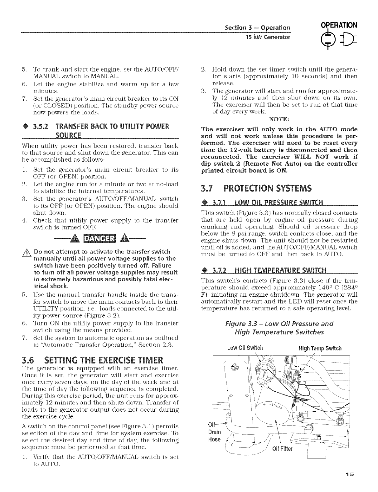
3.7,1 LOW OiL PRESSURESWITCH
This switch (Figure 3.3) has normally closed contacts
that are held open by engine oil pressure during
cranking and operating. Should oil pressure drop
below the 8 psi range, switch contacts close, and the
engine shuts down. The unit should not be restarted
until oil is added, and tile AUTO/OFF/IVIANUAL swifeh
nmst be turned to OFF and then back to AUTO.
TEMPERAT_
This switch's contacts (Figure 3.3) close if tile tem-
perature should exceed approximately 140 ° C (284"
F), initiating an engine shutdown. Tile generator will
automatically restart and the LED will reset once tile
temperature has returned to a safe operating level.
Figure 3.3 -Low Oil Pressure and
High Tempera lure Switches
Low Oil Switch
Drain
Hose
15
MAINTENANCE
Section 4-Maintenance
15 kW Generator
_RANK
This ieature prevents tlle generator irom damaging
itself when it continually attempts to start and anoth-
er problem, such as no fllel supply, prevents it from
starting. Tile unit will crank and rest Ihr a preset time
limit. Then, it will stop cranking, and the LED will
light indicating an overcrank failure. The AUTO/OFF/
MANUAL switch will need to be set to OFF and then
back to AUTO to reset the generator control board.
NOTE:
If the fault is not repaired, the overcrank feature
will continue to activate.
3.7,3.1 Approximate Crank Cyde Times
* 15 seconds ON
. 7 seconds OFF
. 7 seconds ON
. 7 seconds OFF
. Repeat Ior 45 seconds
Approximately 90 seconds total
3.Z4 OVERSPEED
This ieature protects the generator from damage by
shutting it down if it happens to ruts faster than the
preset limit. This protection also prevents the genera-
tor from supplying an output that could potentially
damage appliances connected to the generator cir-
cuit. Contact the nearest dealer if this failure occurs.
4.1 FUSES
The generator panel's 15 amp fuse (Figure 4.1) pro-
tects the DC control circuit against overload. The fllse
is wired its series with the battery output lead to the
panel. If the fllse element has melted open, the engine
cannot crank or start. Replace the fuse using only an
identical 15-amp replacement.
The generator panel's 7.5 amp fllse protects the 12
VDC accessory socket. If the fllse element has melted
open, the 12 VDC socket will not provide power to
any accessories. Replace the/ilse using only an iden-
tical 7.5 amp replacement. To remove fuse, push the
Iuse holder cap down and rotate counterclockwise.
Figure 4. ! -Generator Contro! Pane!
0UTLETFUSE
?;
AUTO OFF
SYSTEM FUSE
O
15A SET
EXERCISE
TIME
16
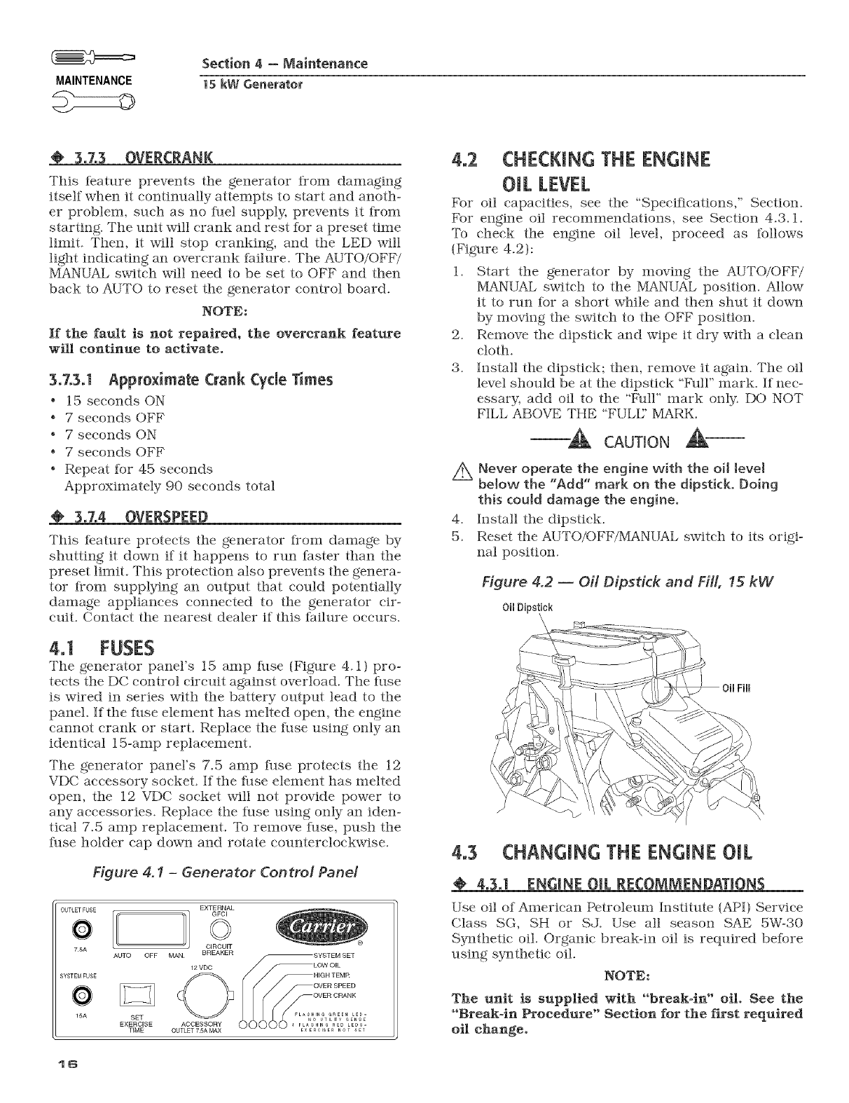
4.2 CHECKING THE ENGINE
OiL LEVEL
For oil capacities, see the "Specifications," Section.
For engine oil recommendations, see Section 4.3.1.
_[% check the engine oil level, proceed as iollows
{Figure 4.2):
1. Start the generator by moving the AUTO/OFF/
MANUAL switch to the IVIANUAL position. Allow
it to run for a short while and then shut it down
by moving the switch to the OFF position.
2. Remove the dipstick and wipe it dry with a clean
cloth.
3. Install the dipstick; then, remove it again. The oil
level should be at the dipstick "l_5lll" mark. If nec-
essary, add oil to the "b)lll" mark only. DO NOT
FILL ABOVE THE "FULE' MARK.
CAUTION
/_ Never operate the engine with the oil JevM
bMow the "Add" mark on the dipstick. Doing
this could damage the engine.
4. Install the dipstick.
5. Reset the AUTO/OFF/MANUAL switch to its origi-
nal position.
Figure 4.2 -- Oi[ Dipstick and Fill, !5 kW
Oil Dipstick
4.3 CHANGING THE ENGINE OIL
4.3.1 ENGINE OIL RECOMMENDATIONS
Use oil of American Petroleum Institute (API) Service
Class SG, SH or SJ. Use all season SAE 5W-30
Synthetic oil. Organic break-in oil is required before
using sy_sthetic oil.
NOTE:
The unit is supplied with "break-in" oil. See the
"Break-in Procedure" Section for the first required
oil change.
Section 4 - Maintenance
15 kW Generator MAINTENANCE
"_ CAUTION
//_ Any attempt to crank or start the engine before
it has been properly serviced with the recom-
mended oil may resuJt in an engine failure.
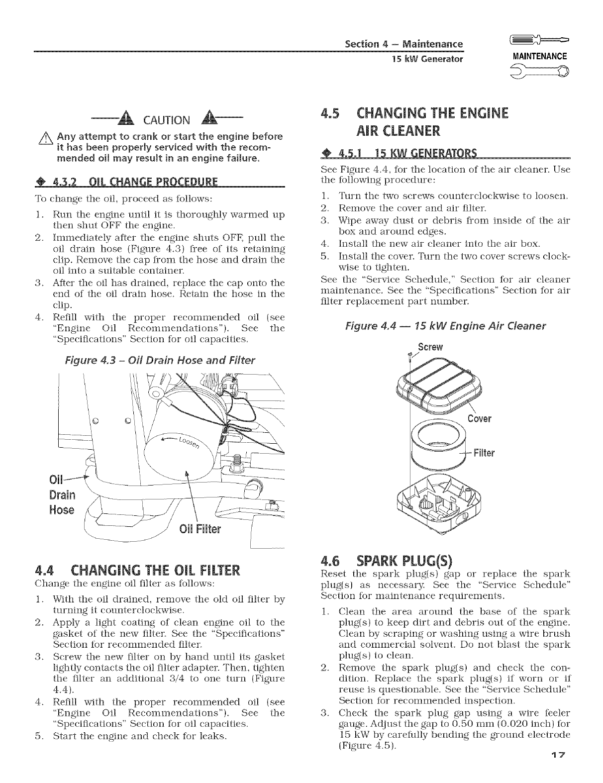
4°3°2 OIL CHANGE PROCEDURE
To change tile oil, proceed as follows:
1. Run the engine until it is thoroughly warmed up
then shut OFF the engine.
2. Immediately after the engine shuts OFE pull the
oil drain hose (Figure 4.3) free of its retaining
clip. Remove the cap from the hose and drain the
oil into a suitable container.
3. After the oil has drained, replace the cap onto the
end of the oil drain hose. Retain the hose in the
clip.
4. Refill with the proper recommended oil (see
"Engine Oil Recommendations"). See the
"Speciiications" Section fhr oil capacities.
Figure 4.3 -Oil Drain Hose and Filter
oil Filter
4.4 CHANGING THE OIL FILTER
Change the engine oil filter as follows:
1. With the oil drained, remove the old oil filter by
turning it counterclockwise.
2. Apply a light coating of clean engine oil to the
gasket of the new filter. See the "Specifications"
Section for recommended filter.
3. Screw the new filter on by hand until its gasket
lightly contacts the oil filter adapter. Then, tighten
the filter an additional 3/4 to one turn {Figure
4.4).
4. Refill with the proper recommended oil (see
"Engine Oil Recommendations"}. See the
"Specifications" Section for oil capacities.
5. Start the engine and check for leaks.
4.5 CHANGING THE ENGINE
AIR CLEANER
4.5.1 15 KW GENERATORS
See Figure 4.4, for the location of the air cleaner. Use
the fbllowing procedure:
1. Turn the two screws counterclockwise to loosen.
2. Remove the cover and air filter.
3. Wipe away dust or debris from inside of the air
box and around edges.
4. Install the new air cleaner into the air box.
5. Install the cover. Turn the two cover screws clock-
wise to tighten.
See the "Service Schedule," Section for air cleaner
maintenance. See the "Specii?cations" Section for air
filter replacement part nmnber.
Figure 4.4 -- 15 kW Engine Air Cleaner
S0rew
over
Filter
4.6 SPARKPLUG(S)
Reset the spark plug(s) gap or replace the spark
plug(s) as necessary. See the "Service Schedule"
Section for maintenance requirements.
1. Clean the area around the base of the spark
plug(s) to keep dirt and debris out of the engine.
Clean by scraping or washing using a wire brush
and commercial solvent. Do not blast the spark
plug(s) to clean.
2. Remove the spark plug(s) and check the con-
dition. Replace the spark plug(s) if worn or if
reuse is questionable. See the "Service Schedule"
Section for recommended inspection.
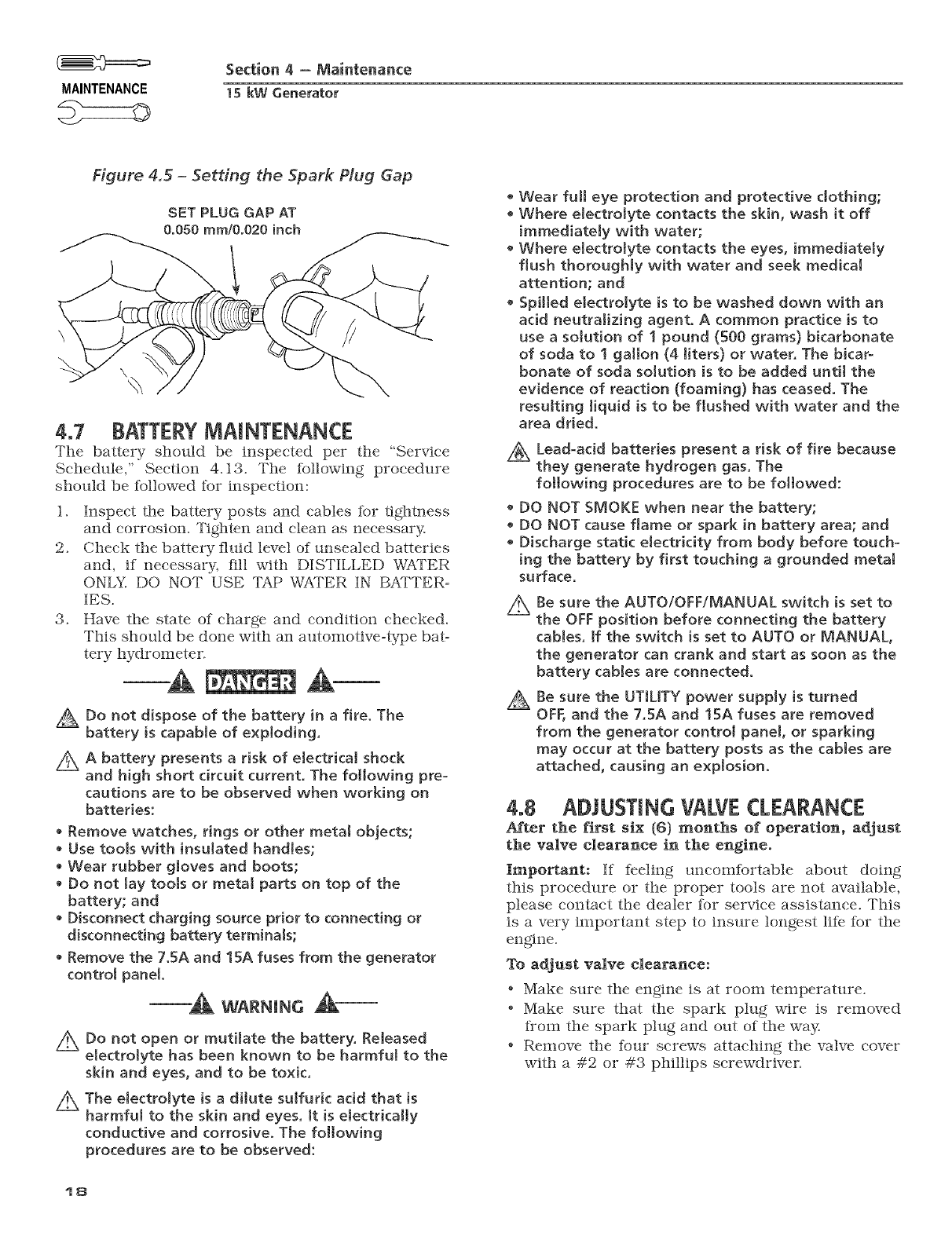
3. Check the spark plug gap using a wire feeler
gauge. Adjust the gap to 0.50 mm (0.020 inch) for
15 kW by careflflly bending the ground electrode
(Figure 4.5). 17
MAINTENANCE
Section 4-Maintenance
1S kW Generator
Figure 4.5 -Setting the Spark Plug Gap
SET PLUG GAP AT
0.050 ram/0.020 inch
4.7 BATTERY MAINTENANCE
The battery should be inspected per the "Service
Schedule," Section 4.13. The ibllowing procedure
should be ibllowed ibr inspection:
1. inspect tile battery posts and cables tbr tightness
and corrosion. Tighten and clean as necessary.
2. Check the battery fluid level of unsealed batteries
and, if necessary, fill with DiSTiLLED WATER
ONLY. DO NOT USE TAP WATER iN B_a'TER-
IES.
3. Have the state of charge and condition checked.
This should be done with an automotbze-type bat-
tery hydrometer.
Do not dispose of the battery in a fire. The
battery is capable of exploding,
Z_ A battery presents a risk of eJectrical shock
and high short circuit current. The following pre-
cautions are to be observed when working on
batteries:
• Remove watches, rings or other metal objects;
Use tools with insulated handles;
• Wear rubber gloves and boots;
• Do not lay tools or metal parts on top of the
battery; and
• Disconnect charging source prior to connecting or
disconnecting battery terminaJs;
Remove the 7.5A and 15A fuses from the generator
control panel. -A wAR.m.c&
/_ Do not open or mutilate the battery. Released
electrolyte has been known to be harmful to the
skin and eyes, and to be toxic.
Z_ The electrolyte is a dilute sulfuric acid that is
harmfuJ to the skin and eyes. Jt is eJectrically
conductive and corrosive. The following
procedures are to be observed:
18
• Wear full eye protection and protective clothing;
• Where electroJyte contacts the skin, wash it off
immediately with water;
• Where eJectroJyte contacts the eyes, immediately
flush thoroughly with water and seek medical
attention; and
Spilted electrolyte is to be washed down with an
acid neutralizing agent. A common practice is to
use a sotution of ! pound (500 grams} bicarbonate
of soda to 1 gallon (4 liters) or water. The bicar-
bonate of soda solution is to be added untit the
evidence of reaction (foaming) has ceased. The
resulting Jiquid is to be flushed with water and the
area dried.
z_ Lead-acid batteries present a risk of fire because
they generate hydrogen gas. The
following procedures are to be followed:
DO NOT SMOKE when near the battery;
DO NOT cause flame or spark in battery area; and
Discharge static eJectricity from body before touch-
ing the battery by first touching a grounded metaJ
surface.
2x
A
Be sure the AUTO/OFF/MANUAL switch is set to
the OFF position before connecting the battery
tames, ff the switch is set to AUTO or MANUAL,
the generator can crank and start as soon as the
battery caMes are connected.
Be sure the UTILITY power supply is turned
OFF, and the 7.5A and 15A fuses are removed
from the generator control panel, or sparking
may occur at the battery posts as the cables are
attached, causing an explosion.
4.8 ADJUSTING VALVE CLEARANCE
After the first six (G) months of operation, adjust
the valve clearance in the engine.
Important: if feeling uneomibrtable about doing
this procedure or the proper tools are not available,
please contact the dealer for service assistance. This
is a very important step to insure longest li% lhr the
engine.
To adjust valve clearance:
* Make sure the engine is at room temperature.
* Make sure that the spark plug wire is removed
irom the spark plug and out of the way.
* Remove the four screws attaching the valve cover
with a #2 or #3 phillips screwdriver.
Section 4 = Maintenance
1SkW Generator MAINTENANCE
.Make sure the piston is at Top Dead Center (TDC)
of its compression stroke (both valves closed). To
get tlle piston at TDC, remove the intake screen at
tlle front of the engine to gain access to the flywheel
nut. Use a large socket and socket wrench to rotate
the nut and hence tile engtae. While watching the
piston through the spark plug hole. Tile piston
should move up and down. Tile piston is at TDC
when it is up as high as it can go.
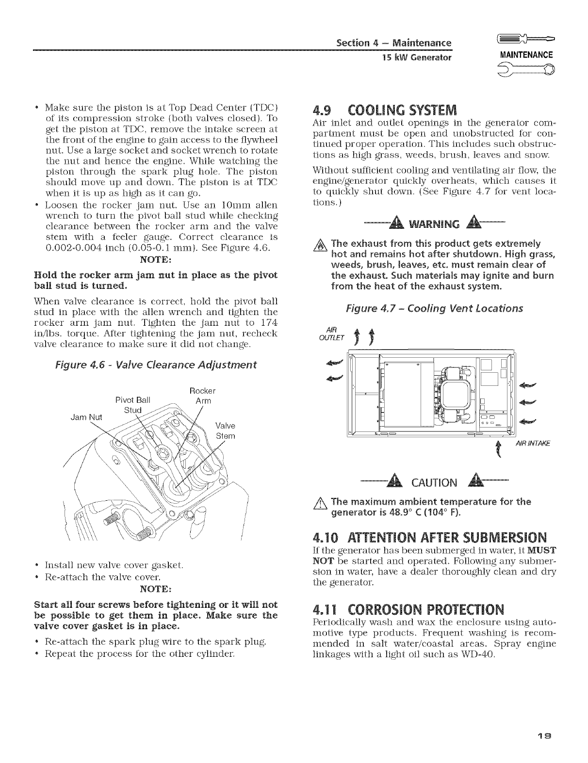
o Loosen tile rocker jam nut. Use an 10ram allen
wrench to turn the pivot ball stud while checking
clearance between tile rocker arm and the valve
stem with a Ieeler gauge. Correct clearance is
0.002-0.004 inch (0.05-0.1 ram). See Figure 4.6.
NOTE:
Hold the rocker arm jam nut in place as the pivot
ball stud is turned.
When valve clearance is correct, hold tile pivot ball
stud ta place with the allen wrench and tighten tile
rocker arm jam nut. Tighten tile jam nut to 174
ta/lbs, torque. After tightening tile jam nut, recheck
valve clearance to make sure it did slot change.
Figure 4.6 -Valve Clearance Adjustment
Jam Nut
Pivot Ball
Stud
Rocker
Arm
Valve
Stem
4,9 C00UNG SYSTEM
Air talet and outlet openings ta tile generator eo!n-
partment must be open and unobstructed for con-
ttaued proper operation. This includes such obstruc-
tions as high grass, weeds, brush, leaves and snow.
Without sufficient eooltag and ventilating air flow, the
engine/generator quickly overheats, which causes it
to qtaekly shut down. (See Figure 4.7 lhr vent loca-
tions. )
-_ WARNING _-
/_ The exhaust from this product gets extremely
hot and remains hot after shutdown. High grass,
weeds, brush, leaves, etc. must remain dear of
the exhaust. Such materiMs may ignite and burn
from the heat of the exhaust system.
Figure 4.7- Cooling Vent Locations
t/dR INTAKE
°Install slew valve cover gasket.
o Re-attach the valve cover.
NOTE:
Start all four screws before tightening or it will not
be possible to get them in place. Make sure the
valve cover gasket is in place,
oRe-attach the spark plug wire to tile spark plug.
, Repeat the process lot the other cylinder.
CAUTION
Z_ The maximum ambient temperature for the
generator [s 48.9 ° C (104 ° F).
4.10 ATTENTION AFTER SUBMERSION
If the generator has been submerged ta water, it MUST
NOT be started and operated. Followtag any submer-
sion in water, have a dealer thorolNhly clean and dry
the generator.
4,11 CORROSIONPROTECTION
Periodically wash and wax tile enclosure using auto-
motive type products. Frequent washing is recom-
mended in salt water/coastal areas. Spray engtae
linkages with a light oil such as WD-40.
19
MAINTENANCE
Section 4-Maintenance
1S kW Generator
@4.11.1 ADDITIONAL CORROSION
PROTECTION
Periodically spray all engine linkage parts and brack-
ets with corrosion inhibiting spray such as WD=40 or
a comparable product.
4.12 OUT OF SERVICE PROCEDURE
@ 4o12.1REMOVAL FROM SERVICE
If the generator cannot be exercised every seven days,
and will be out of service longer than 90 days, pre-
pare tile generator Ior storage as Iollows:
1. Start the engine and let it warm tip.
2. Close the fuel shutoff valve in the fuel supply line
and allow the unit to shut down.
3. Once the unit has shut down, it will signal a low
oil fault.
4. Set the generator's main circuit breaker to its
OFF (or open) position.
5. Set the Auto/Oft/Manual switch to OFF and
turn off the utility power to the transfer switch.
Remove the 7.5A and 15A fllses from the genera=
tor control panel. Disconnect the battery cables
as outlined in "General Hazards" {page 2). Turn
on the utility power supply to the transfer switch
in order to power the emergency load centers cir-
cuits while utility" power is awJilable.
G. While the engine is still warm from running,
drain the oil completely. ReIill the crankcase with
oil. See "Engine Oil Recommendations," Section.
7. Attach a tag to the engine indicating the viscosity"
and classification of the oil in the crankcase.
8. Remove the spark plug(s) and spray fo_ging
agent into the spark plug(s) threaded openings.
Reinstall and tighten the spark plug(s).
9. Remove the battery and store it in a cool, dry
room on a wooden board. Never store the battery
on any concrete or earthen floor.
10. Clean and wipe the entire generator.
4o12o2 RETURN TO SERVICE
To return the unit to service after storage, proceed
as follows:
1. Verify that utility power is turned off and that the
Auto/Off/Manual switch is set to OFF
2. Check the tag on the engine for oil viscosity- and
classification. Verify" that the correct reeom=
mended oil is used in the engine (see "Engine Oil
Recommendations"). If necessary, drain and refill
with the proper oil.
3. Cheek the state of the battery. Fill all cells of
unsealed batteries to the proper level with dis°
tilled water. DO NOT USE TAP WATER IN THE
BATTERY. Recharge the battery to I00 percent
state of charge, or, if defective, replace the bat=
tery. See the "Specifications" Section, ior type and
size.
4. Clean and wipe the entire generator.
5. Remove the 7.5A and 15A fuses Kom the genera=
tor control panel. Reconnect the battery. Observe
battery polarity. Damage may occur if the battery
is connected incorrectly.
6. Open the iuel shutoff valve.
7. Insert the 7.5A and 15A fuses into the generator
control panel. Start the unit by moving the Auto/
Off/Manual switch to MANUAL. Allow the unit to
warm up thoroughly.
8. Stop the unit by setting the Auto/Off/Manual
switch to OFF
9. Turn on the utility power to the transfer switch.
10. Set the Auto/Off/Manual switch to AUTO.
1 1. The generator is now ready Ior service.
NOTE:
If the battery was dead or disconnected, the exer-
cise timer must be reset,
2O
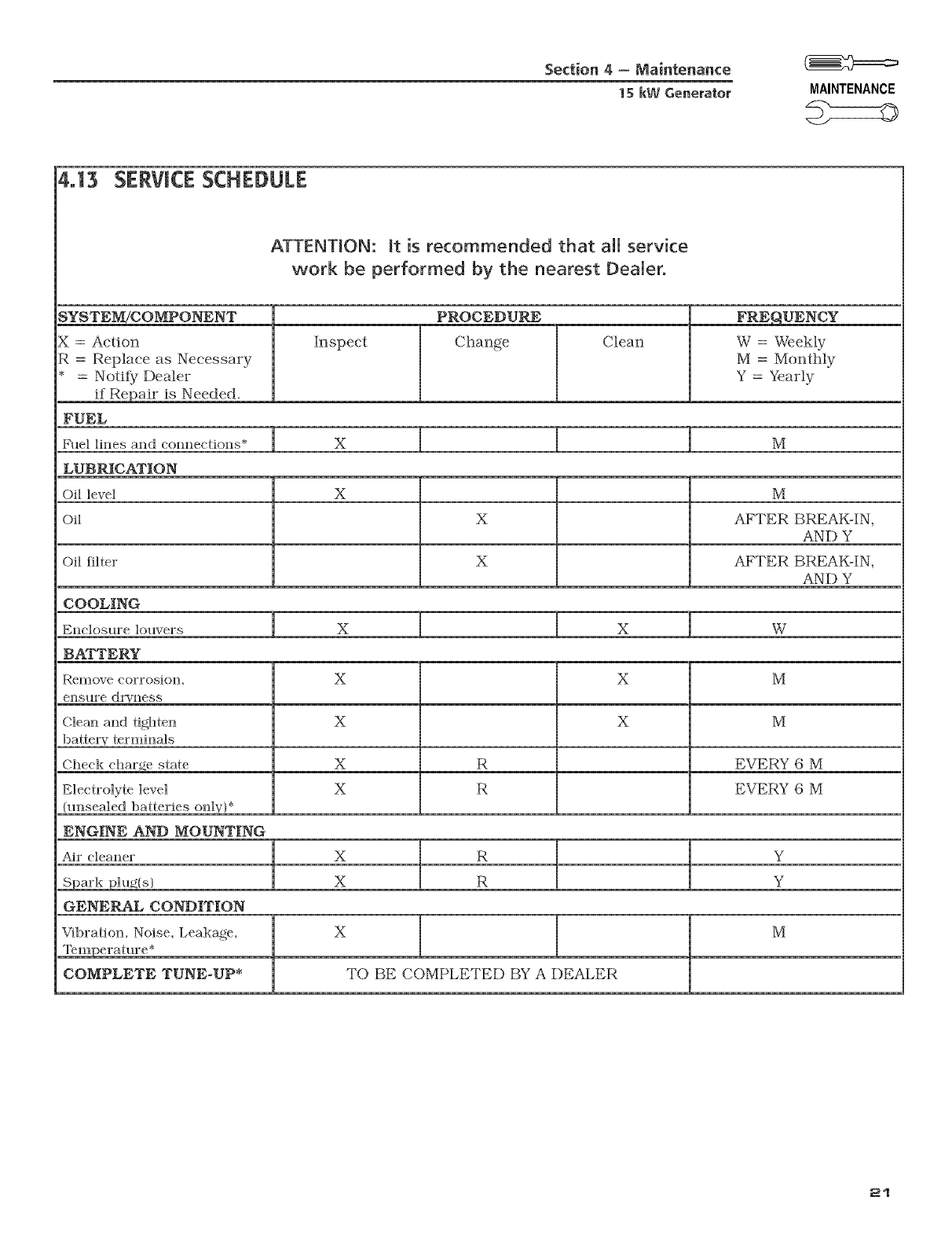
Section 4 = Maintenance
15 kW Generator MAINTENANCE
4.13 SERVICESCHEDULE
ATTENTION: _t is recommended that all service
work be performed by the nearest Dealer.
SYSTEM[COMPONENT
X=Action
R=Replace as Necessary
* = Notify Dealer
if Repair is Needed.
FUEL
PROCEDURE
Inspect Change Clean
FRE_qUENCY
W = Weekly
M = Monthly
Y = Yearly
Fuel lines and connections* X M
LUBRICATION
Off level X M
Off X AFTER BREAK-IN,
AND Y
Off filter X AFTER BREAK-IN,
AND Y
COOLING
Enclosure ]ouvers X X W
BATTERY
Remove corrosiolL X X M
ensllre dl%ness
X X M
bagel T terminals
Check charge state X R EVERY G M
Electrolyte level X R EVERY 6 M
(unsealed batteries only}*
ENGINE AND MOUNTING
Air cleaner X R Y
Spark plu_{s} X R Y
GENERAL CONDITION
Vfl)ration, Noise, Leakage, X M
COMPLETE TUNE-UP* TO BE COMPLETED BY A DEALER
21
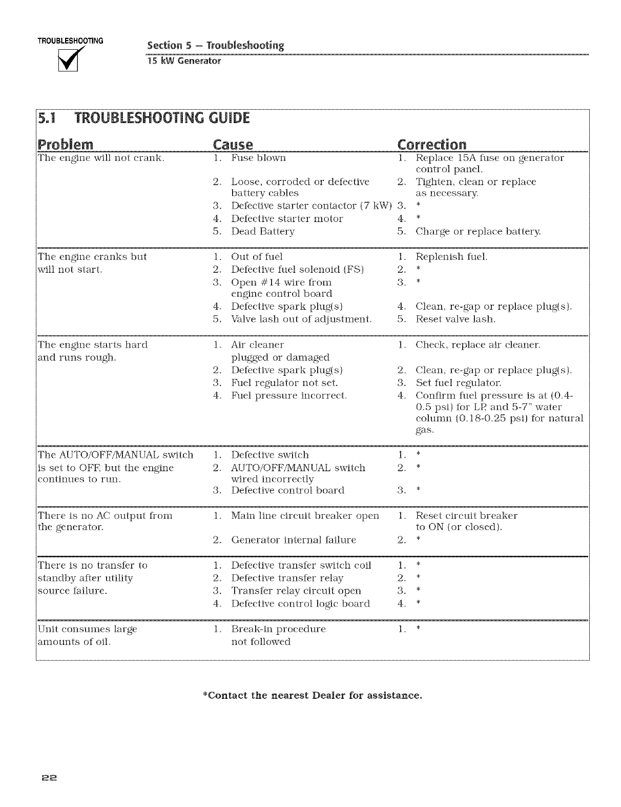
TROUBLESHOOTING Section 5=Troubleshooting
1S kW Generator
5.1 TROUBLESHOOTING GUmDE
Cause
Tile engine will not crank. 1. Fuse blown
2. Loose, corroded or detective
battery cables
3. Defective starter eontaetor (7 kW) 3.
4. Defective starter motor 4.
5. Dead Battery 5.
Correction
1. Replace 15A fllse oil generator
control panel.
2. Tighten, clean or replace
as necessary.
Charge or replace battery.
Tile engine cranks but
will not start.
1. Out offllel
2. Defective fllel solenoid (FS)
3. Open #14 wire flom
engine control board
4. Defective spark plug{s)
5. Valve lash out of adjustment.
1. Replenish fuel.
2. *
3. *
4. Clean, re-gap or replace plug(s).
5. Reset valve lash.
Tile engine starts hard
and runs rough.
1. Air cleaner
plugged or damaged
2. Detective spark plug(s) 2.
3. Fuel regulator not set. 3.
4. Fuel pressure incorrect. 4.
1. Cheek, replace air cleaner.
Clean, re-gap or replace plug(s).
Set fllel regulator.
Confirm fllel pressure is at (0.4-
0.5 psi) ti)r LR and 5-7" water
eohmm (0.18-0.25 psi) for natural
gas.
Tile AUTO/OFF/I_NUAL switch
is set to OFR but tile engine
continues to run.
1. Deleetive switch 1. *
2. AUTO/OFF/MANUAL switch 2. *
wired incorrectly
3. Defective control board 3. *
There is no AC output from
the generator.
1. Main line circuit breaker open 1. Reset circuit breaker
to ON (or closed).
2. Generator internal l_tilure 2. *
There is no transfer to
standby alter utility
source failure.
1. Defective transler switch coil 1. *
2. Defective transfer relay 2. *
3. Transfer relay circuit open 3. *
4. Defective control logic board 4. *
Unit consumes large 1. Breakqn procedure 1. *
amounts of oil. not followed
*Contact the nearest Dealer for assistance,
22
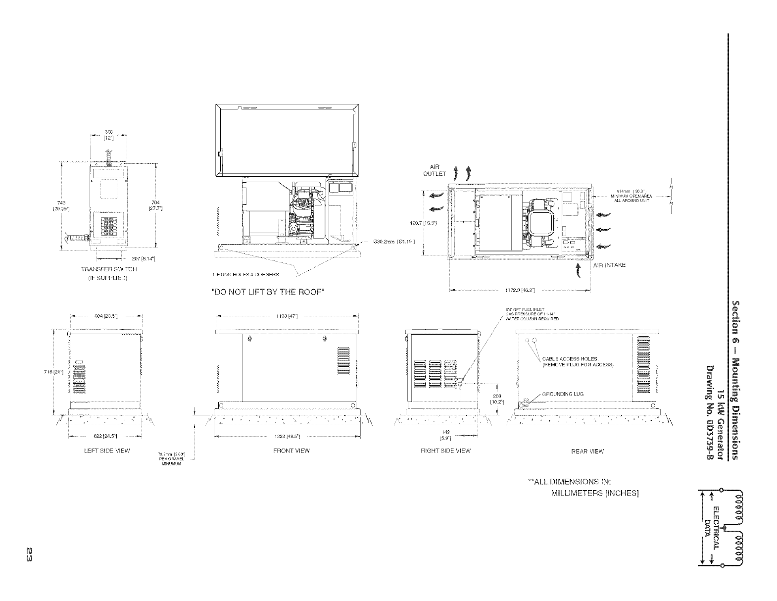
743
/2s ',i
716tze
308
i iI
7O4
i [27,7"j
-. v
207 [8.14"]
TRANSFER SWITCH
(IF SUPPLIED)
604 [23,5"] _-
622 [24,5'_J
LEFT S_DE VEW 76,2mm [300]
pEAGRAVEL
M]NUMUM
L
UFT[NG HOLES 4-CORNERS
"DO NOT LEFT BY THE ROOF"
1193 [47"] _'
FRONT VIEW
AIR
OUTLET 1_
i_- ,_ F_...................___11_
030.2; nt n [Ol19"1 ; /' _ - ¢°°F_
t
..... 1172.3 [462"1
I
#14ram [ 24_0" _,_
M_NIMUMOPEN AREA
ALL AROUND UNiT
A:'_ N lAKE
94 NPT FUEL iNLET
GAS PRESSUREOF 11 14'
WATER COLUMN REQUIRED
// i E•\
\: CABLE ACCESS HOLES•
_/:;', ' [REMOVE PLUG FOR ACCESS/
_==_
260
_ {_°_"_ )I,'\\
149
L5.9"]
RIGHT SIDE VIEW REAR VIEW
**ALL DIMENSIONS IN:
MILLIMETERS [INCHES]
t#
s=.
I
No
N
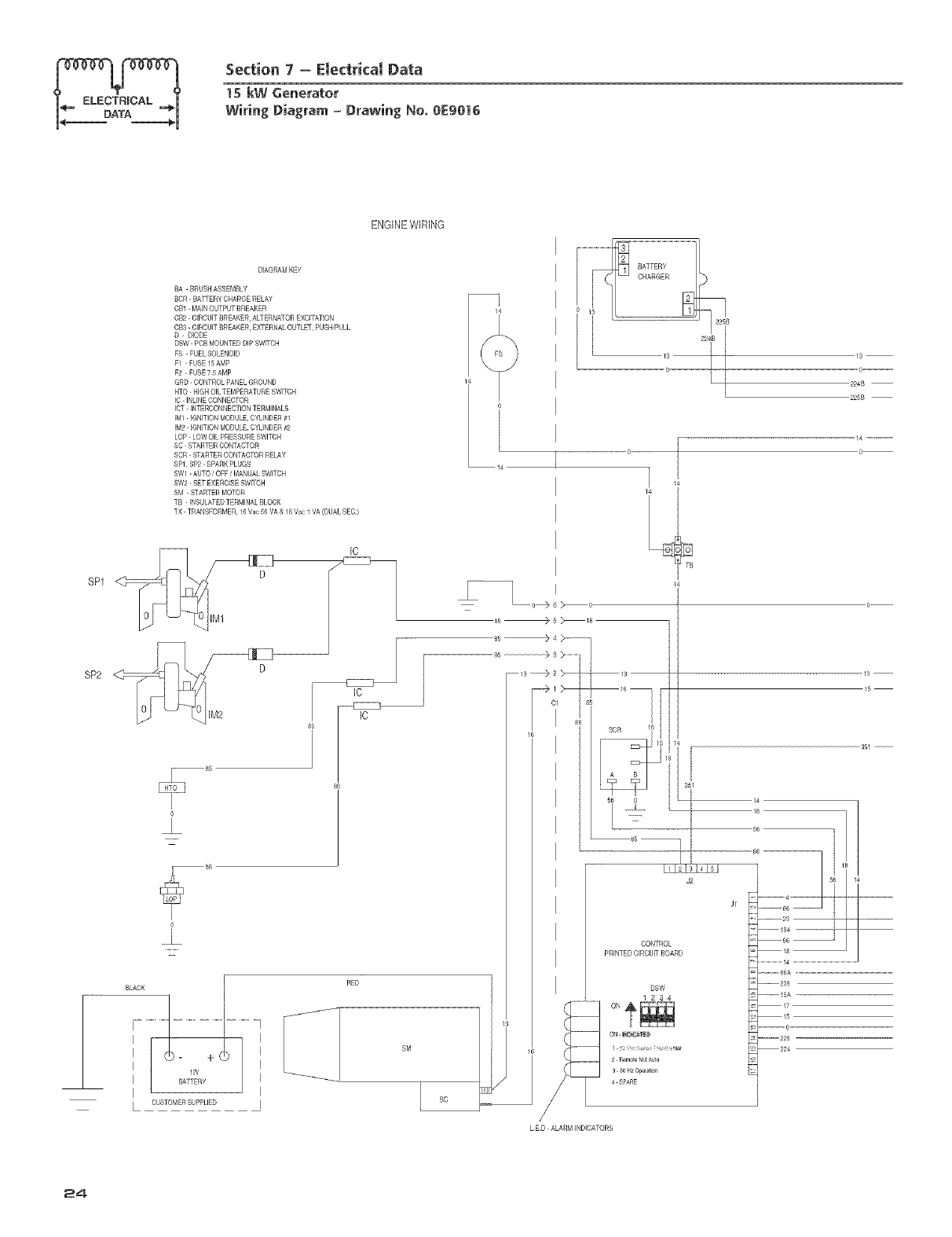
Section 7 - Electrical Data
ms kW Generator
Wiring Diagram = Drawing No. 0E9016
ENGINE WIRING
DIAGRAM KEY
BA -BROBR ASSEMBLY
RCR- BATTERY CRAROB RELAY
CR1 -fv'AINOL_PUT BREAKER
CR2- CIRCUIT RRBAKBR, ALTERNATOR BXCI FATION
CR3- CIRCUIT RRBAKER, EXTERNAL OUTLET, RUSH/PULL
D-DIODE
DSW kPCR fv'OBNTBD DIP SWITCH
FB -FUEL SOLENOID
F1 kFUSE 15AMP
F2 kFUSE75 AMP
ORB- CONTROL PANEL GROUNB
HTO kNIGH OIL TEMPERATURE SW[TOH
IC kINL[NB CONNECTOR
ICT- INTEROONNECTIONTERMINALS
IM1k IGNITION MODULE, CYUNBBR #1
IN2 _ IGNITION PODULB, CYUNBBR #2
LOP- LOWOIL PRESSURE SWITCH
SC- STARTER CONTACTOR
SCR -STARTER CONTACTOR RELAY
SPl_ SP2 kSPARK PLUGS
SW1 kAUTO /OFF /MANUAL SWITCR
SW2 kBET EXERCISE SWITOR
SM -STARTER MOTOR
_B -INSULATEDTERMIBAL BLOCK
TX- TRANSFORMER, 16 Vac 56 VA & 1_ Vac 1 VA (DUAL SBC)
SP1
SP2 D
IC
RED
OUSTOMERSUPPLIED
19--
0
224B
225B
o
14
_ e >_o
18 >5 }18
TB
OR 16
_ u
85
J2
CONTROL
PRINTED CIRCUIT BOARD
DSW
1234
1
2RemoteNotAuto
3 SOHz Oneration
4 SPARE
13
15
........... 66A ..........................................................................
--28g
--15A
17
15
--0
--225
-- 224
LED- ALARM INDICA'_RB
24
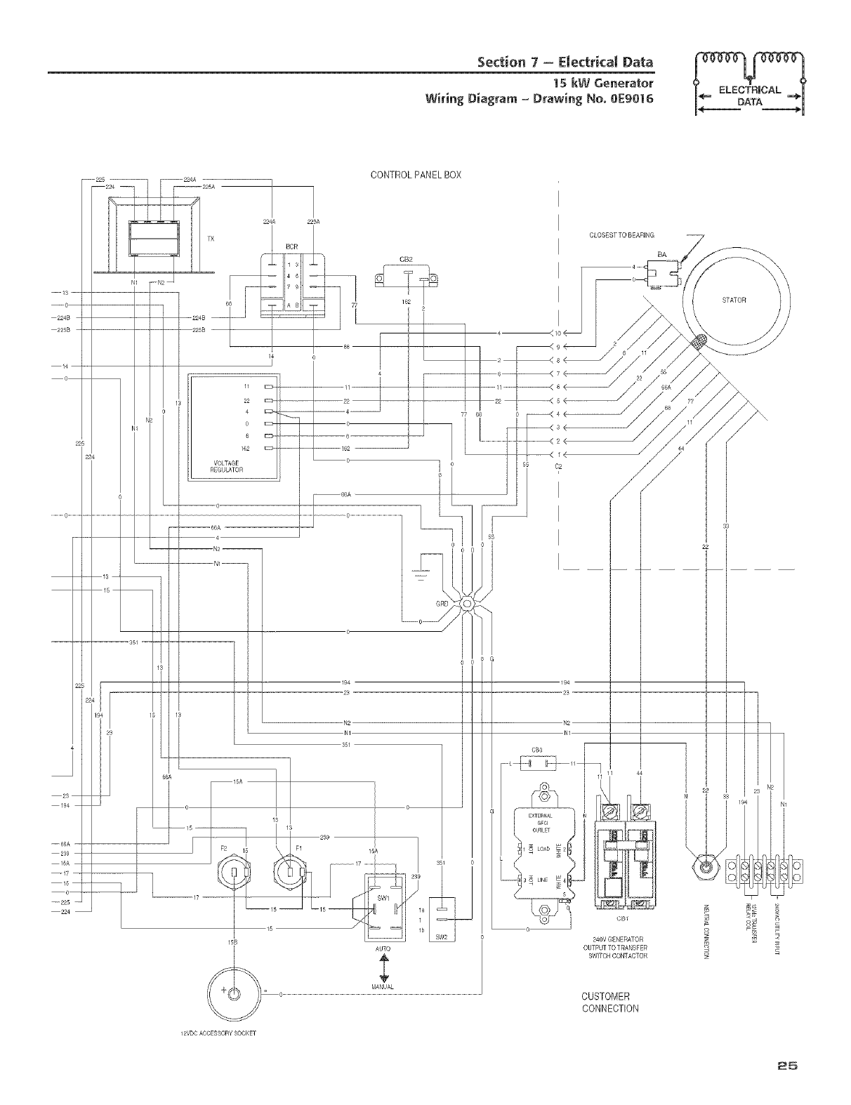
Section 7 = Emectrical Data
1S kW Generator
Wiring Diagram = Drawing No. 0E9016
194
--66A
CONTROLPANELBOX
224A
BCR
225A
CB2
11
22
4
o
6
162
VOLTAGE
REGULATOR
77 66
194
23
N2
N1
551
/
15B
CLOSEST TO BEARING
BA
STATOR
240V GENERATOR
OUTPUTTO TRANSFER
SWITCHCONTACTOR z
E
12VDCACCESSORYSOCKET
CUSTOMER
CONNECTION
25
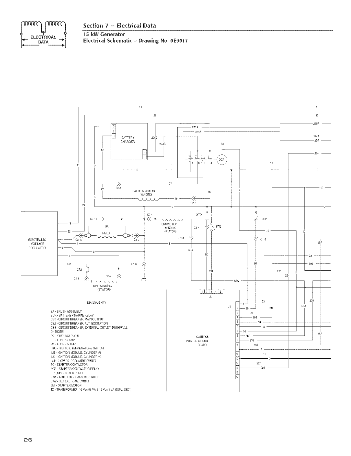
Section 7 m Electrical Data
1S kW Generator
EmectricamSchematic_ Drawing No. 0E9017
ELECTRONIC
VOLTAGE
REGULATOR
7_ BATTERY CHARGE
162 qo 6
C2-8 2
DPE WINDING
(STATOB)
DIAGRAMKEY
BA - BRUSHASSEMBLY
BCR- BATTERYCHARGERELAY
CB1- CIRCUITBREAKER,MAINOUTPUT
CB2- QRCU]T BREAKER,ALT EXCITATION
CB3- CIRCUITBREAKER,EXTERNALOUTLET,PUSH/PULL
D- DIODE
FB - FUELSOLENOID
F1 - FUSE 15AMP
F2 - FUSE 75 AMP
HTO- HIGHOIL TEMPERATURESWITCH
]M1-IGNITIONMODULE,CYLINDER#1
]M2-]GNmON MODULE,CYLINDER#2
LOP- LOWOIL PRESSURESWITCH
SC- STARTERCONTACTOB
SCR- STARTERCONTACTORRELAY
BP1,BP2 - SPARKPLUGS
BW1- AUTO/OFF /MANUALSWITCH
BW2- SET EXERCISESdITCH
SM -STARTERMOTOR
TX- TRANSFORMER,16Vac_ VA & 16Vac 1VA (DUALSEC)
I1
22 ..........................................................................................................................................................................................................................................................................................................................................22
WINDING
02-2
6
6
sw2 L
BTO
ENGINE RUN
WINDING
(STATOR)
C2-3
CONTROL
PRINTEDCIRCUIT
BOARD
LOP
14
01-3
23
-- 194
--- 56 --
_o
--14
w_ 68A
239
15A
17
15
6
.............................225 ......................................
-- 224
j225A
224A
226
224 --
--13 --
O
15A
26
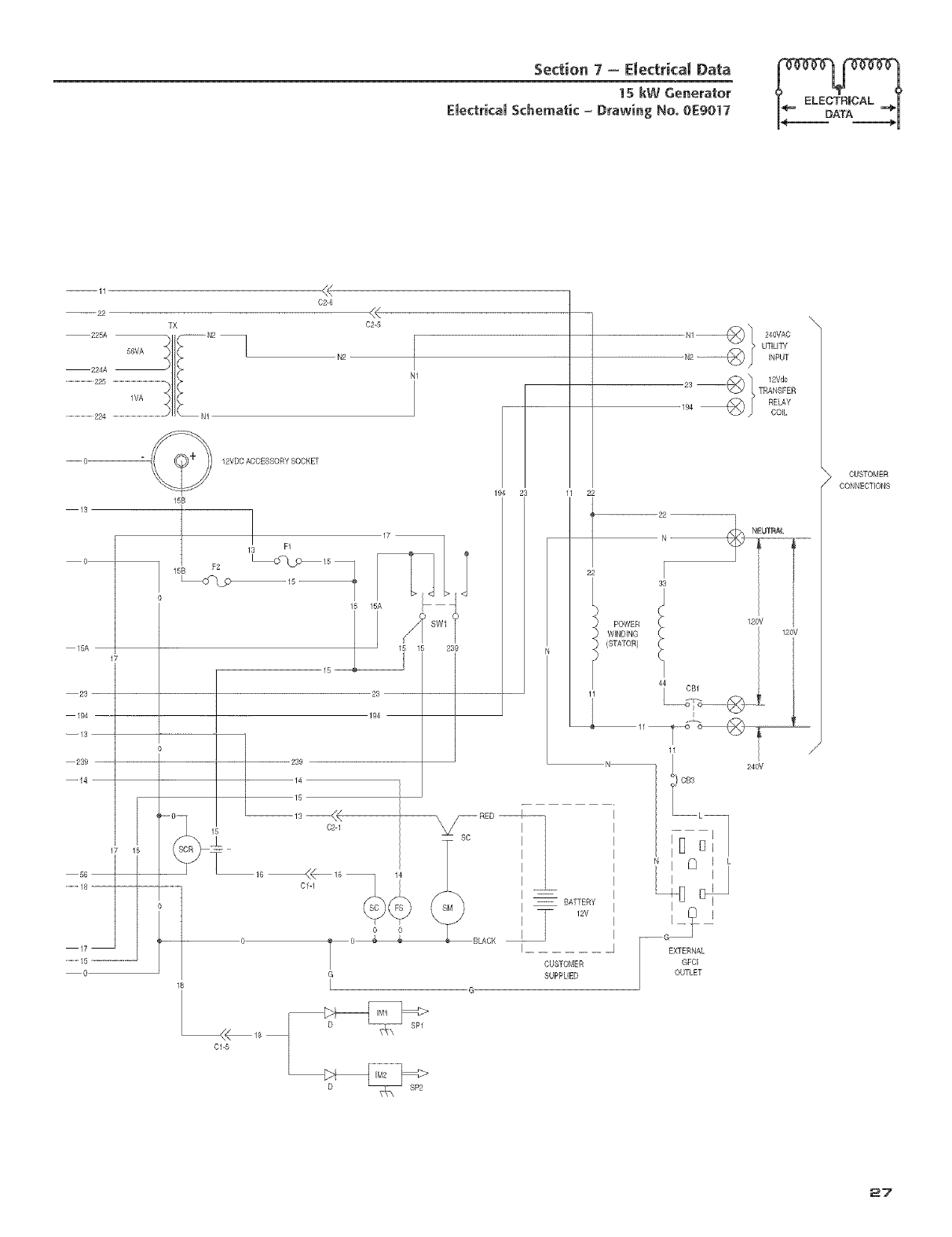
Section 7 - Emectrical Data
15 kW Generator
£mectricamSchematic -Drawing No. 0E9017
224A
..............................225
..............................224
13
56VA
C2_6
-- 15A
23
194
--13
0
15
i
.............18
17
...........15
0
239
14
--_3 --<<
C2q
C1-1
<(
02-5
0
T
G
L
194 23
239
23
194
N ....
POWER i ! 120V 1201V
WENDENG
(STATOR)u_
11
N
BLACK
-- BATTERY
12V
CUSTONER
SUPPLIED
b E
I _
--G
I EXTERNAL
GFCE
OUTLET
240V
CUSTOMER
CONNECTIONS
-<_18
01 5
27
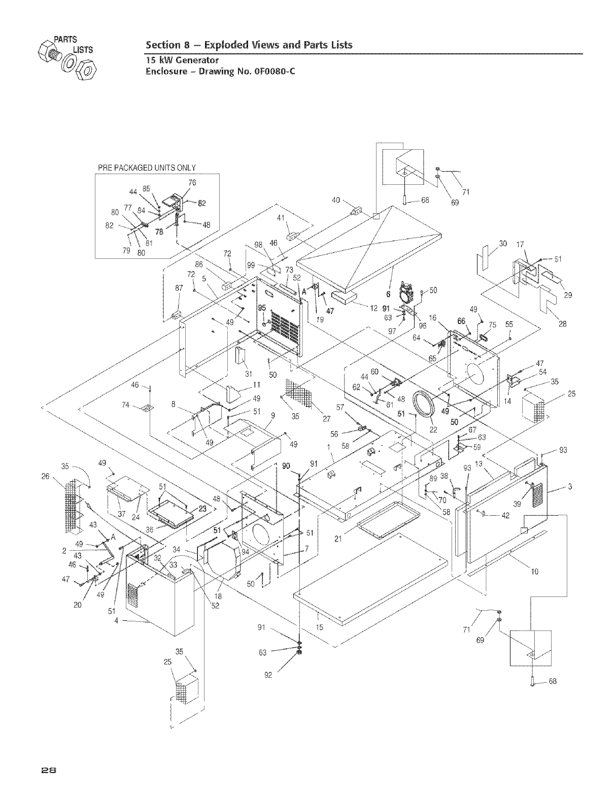
_@ RTSISTS Section 8-E×ploded Views and Parts lists
15 kW Generator
Encmosure= Drawing No. oFooso-c
PREPACKAGED UNITS ONLY
7_
40 \\
69
7I
30 17
< <
35_ 49
26 ,\
47
2O
31 50 r44 60
_11
8 _. 57
51 9 35 27
< 56
49 1 58
\
34
35
52
25
63
92
<
g3 13
39
_S........42
10
.)
f
/
P
28
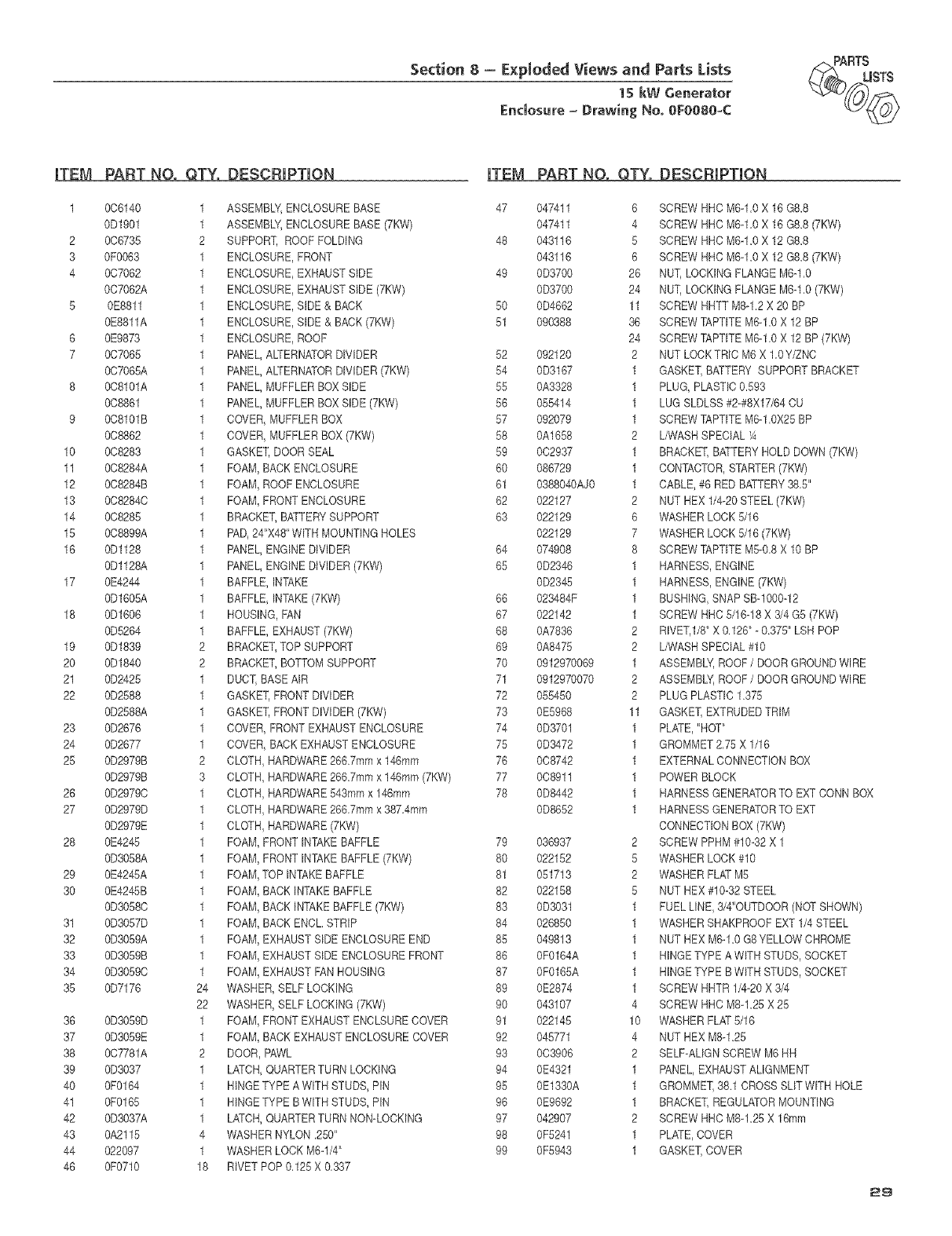
Section 8- E×pIoded Views and Parts Lists
15 kW Generator
Enclosure = Drawing No. eFO080-C
_(_,_ RTtmSTS
iTEM PART NO. QTY.
1 006140 1
0D1901 1
2 006735 2
3 0F0063 1
4 007062 1
007062A 1
5 0E8811 1
0E8811A 1
6 0E9873 1
7 007065 1
007066A 1
8 008101A 1
008861 1
9 008101B 1
008862 1
10 008283 1
11 008284A 1
12 008284B 1
13 0082840 1
14 008285 1
15 008899A 1
16 0Dl128 1
0D1128A 1
17 0E4244 1
0D1605A 1
18 0D1606 1
0D5264 1
19 0D1839 2
20 0D1840 2
21 0D2425 1
22 0D2588 1
0D2588A 1
23 0D2676 1
24 0D2677 1
25 0D2979B 2
0D2979B 3
26 0D29790 1
27 0D2979D 1
0D2979E 1
28 0E4245 1
0D3058A 1
29 0E4245A 1
30 0E4245B 1
0D30680 1
31 0D3057D 1
32 0D3069A 1
33 0D3069B 1
34 0D30590 1
35 0D7176 24
22
36 0D3059D 1
37 0D3059E 1
38 007781A 2
39 0D3037 1
40 0F0164 1
41 0F0165 1
42 0D3037A 1
43 0A2115 4
44 022097 1
46 0F0710 18
DESCBIPTION
ASSEMBLY,ENCLOSUREBASE
ASSEMBLY,ENCLOSUREBASE(7KW)
SUPPORT, ROOFFOLDING
ENCLOSURE,FRONT
ENCLOSURE,EXHAUSTSIDE
ENCLOSURE,EXHAUSTSIDE(7KW)
ENCLOSURE,SIDE& BACK
ENCLOSURE,SIDE& BACK(7KW)
ENCLOSURE,ROOF
PANEL,ALTERNATORDIVIDER
PANEL,ALTERNATORDIVIDER(7KW)
PANEL,MUFFLERBOXSIDE
PANEL,MUFFLERBOXSIDE (7KW)
COVER,MUFFLERBOX
COVER,MUFFLERBOX (7KW)
GASKET,DOOR SEAL
FOAM,BACKENCLOSURE
FOAM,ROOFENCLOSURE
FOAM,FRONTENCLOSURE
BRACKET,BATTERYSUPPORT
PAD,24"X48"WITHMOUNTINGHOLES
PANEL,ENGINEDIVIDER
PANEL,ENGINEDIVIDER(7KW)
BAFFLE,INTAKE
BAFFLE,INTAKE(7KW)
HOUSING,FAN
BAFFLE,EXHAUST(7KW)
BRACKET,TOP SUPPORT
BRACKET,BOTTOMSUPPORT
DUCT,BASEAIR
GASKET,FRONT DIVIDER
GASKET,FRONT DIVIDER(7KW)
COVER FRONTEXHAUSTENCLOSURE
COVER BACKEXHAUSTENCLOSURE
CLOTH HARDWARE266.7mmx 146mm
CLOTH HARDWARE266.7mmx 146mm(7KW)
CLOTH HARDWARE543mmx 146mm
CLOTH HARDWARE266.7mmx 387.4mm
CLOTH HARDWARE(7KW)
FOAM FRONTINTAKEBAFFLE
FOAM FRONTINTAKEBAFFLE(7KW)
FOAM TOP INTAKEBAFFLE
FOAM BACKINTAKEBAFFLE
FOAM BACKINTAKEBAFFLE(7KW)
FOAM BACKENCL STRIP
FOAM EXHAUSTSIDEENCLOSUREEND
FOAM EXHAUSTSIDEENCLOSUREFRONT
FOAM EXHAUSTFANHOUSING
WASHER,SELFLOCKING
WASHER,SELFLOCKING(7KW)
FOAM,FRONTEXHAUSTENCLSURECOVER
FOAM,BACKEXHAUSTENCLOSURECOVER
DOOR,PAWL
LATCH,QUARTERTURNLOCKING
HINGETYPE A WITH STUDS,PIN
HINGETYPE B WITH STUDS,PIN
LATCH,QUARTERTURNNON-LOCKING
WASHERNYLON.250"
WASHERLOCKM6d/4"
RIVET POP 0,125X 0,337
|YEM PART NO. QTY. DESCRIPTION
52
54
55
56
57
58
59
60
61
62
63
66
67
68
69
70
71
72
73
74
75
76
77
78
79
80
81
82
83
84
85
86
87
89
9O
91
92
93
94
95
96
97
98
99
047411 6 SCREW RRCM6A.0 X 16 G8.8
047411 4 SCREWHHCM6d .0 X 16 G8.8(7KW)
043116 5 SCREWHHCMSd.0 X 12 G8.8
043116 6 SCREWHHCM6d .0 X 12 G8.8(7KW)
0D3700 26 NUT,LOCKINGFLANGEM6A.0
0D3700 24 NUT,LOCKINGFLANGE M6A.0 (7KW)
0D4662 11 SCREW HHTTM8-1.2X 20 BP
090388 36 SCREWTAPTITEMTd .0 X 12 BP
24 SCREWTAPTITEM6d .0 X 12 BP(7KW)
092120 2 NUT LOCKTRIO M6 X 1.0Y/ZNC
0D3167 1 GASKET,BATTERYSUPPORTBRACKET
0A3328 1 PLUG,PLASTIC0.593
055414 1 LUG SLDLSS#2-#8X17/64CU
092079 1 SCREWTAPTFE M6d .0X25BP
0A1658 2 L/WASHSPECIAL_A
002937 1 BRACKET,BATTERYHOLD DOWN(7KW)
086729 1 CONTACTOR,STARTER(7KW)
0388040AJ0 1 CABLE,#6 RED BATTERY38.5"
022127 2 NUT HEX 1/4-20STEEL(7KW)
022129 6 WASHERLOCK5/16
022129 7 WASHERLOCK5/16(7KW)
074908 8 SCREWTAPTITEM5-0.8X 10 BP
0D2346 1 HARNESS,ENGINE
0D2345 1 HARNESS,ENGINE(7KW)
023484F 1 BUSHING,SNAPSB-1000A2
022142 1 SCREWHHC5/16-18X 3/4G5 (7KW)
0A7836 2 RIVET,I/8" X 0.126"- 0.375"LSH POP
0A8475 2 L/WASHSPECIAL#10
0912970069 1 ASSEMBLY,ROOF/DOORGROUNDWIRE
0912970070 2 ASSEMBLY,ROOF/DOORGROUNDWIRE
055450 2 PLUG PLASTIC1.375
0E5968 11 GASKET,EXTRUDEDTRIM
0D3701 1 PLATE,"HOT"
0D3472 1 GROMMET2.75 X 1/16
008742 1 EXTERNALCONNECTIONBOX
008911 1 POWERBLOCK
0D8442 1 HARNESSGENERATORTO EXT CONNBOX
0D8652 1 HARNESSGENERATORTO EXT
CONNECTIONBOX (7KW)
036937 2 SCREWPPHM#10-32X 1
022152 5 WASHERLOCK#10
051713 2 WASHERFLATM5
022158 5 NUT HEX#10-32 STEEL
0D3031 1 FUEL LINE,3/41'OUTDOOR(NOT SHOWN)
026850 1 WASHERSHAKPROOFEXT 1/4 STEEL
049813 1 NUT HEXM6d .0 G8YELLOWCHROME
0F0164A 1 HINGETYPE A WITH STUDS,SOCKET
0F0165A 1 HINGETYPE B WITH STUDS,SOCKET
0E2874 1 SCREW HHTR1/4-20 X 3/4
043107 4 SCREWHHCMSd.25 X 25
022145 10 WASHERFLAT5/16
045771 4 NUT HEX M8-1.25
003906 2 SELF-ALIGNSCREW M6 HH
0E4321 1 PANEL,EXHAUSTALIGNMENT
0E1330A 1 GROMMET,38.1 CROSSSLIT WITH HOLE
0E9692 1 BRACKET,REGULATORMOUNTING
042907 2 SCREWHHCMSd.25 X 16ram
0F5241 1 PLATE,COVER
0F5943 1 GASKET,COVER
29
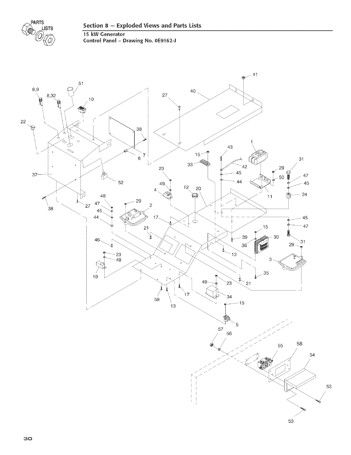
_<_ RTSISTS Section 8-E×ploded Views and Parts lists
15 kW Generator
ContromPanem- Drawing No. 0E91624
22
8,9
\\ 8,32
i
38
27
\
23
4
i 48
\27 47 \ _ 29
I 2
44 17_
L
43
_- 45
47
30
2_ \31
55 58
/
/54
/
/
53
3o
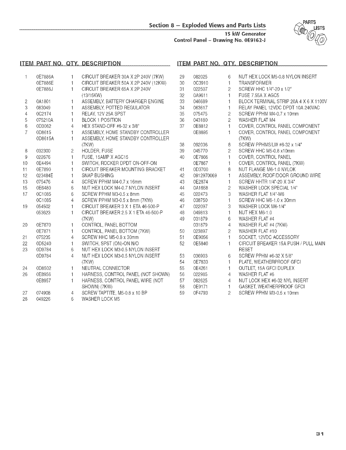
Section 8- E×pIoded Views and Parts Lists
15 kW Generator
CentromPanem=Drawing No. eE9162-_
)_RTtmSTS
mTEM
1
PART NO. QTY.
0E7886A 1
0E7886E 1
0E7886J 1
2 0A1801 1
3 083049 1
4 0C2174 1
5 075210A 1
6 0D3062 4
7 0D8815 1
0D8815A 1
8 032300 2
9 022678 1
10 0E4494 1
11 0E7890 1
12 023484E 1
13 075478 4
15 0E6480 6
17 0C1085 6
0C1088 4
19 054502 1
053623 1
20 0E7870 1
0E7871 1
21 075235 4
22 0D5240 1
23 0D9784 8
0D9784 4
24 0D8802 1
28 0E8956 1
0E8957 1
27 074908 4
28 049226 6
DESCRIPTION |YEM PART NO. QTY. DESCRiPTiON
CIRCUITBREAKER30AX 2P 240V (7KW) 29 082025
CIRCUITBREAKER50A X 2P 240V (12KW) 30 0C3910
CIRCUITBREAKER85AX 2P240V 31 022507
(13/15KW) 32 0A9611
ASSEMBLY,BATTERYCHARGERENGINE 33 046689
ASSEMBLY,POTTEDREGULATOR 34 063617
RELAY,12V25ASPST 35 075475
BLOCK1 POSITION 38 043180
HEXSTAND-OFF#8-32x 3/8" 37 0E8812
ASSEMBLY,HOMESTANDBYCONTROLLER 0E8895
ASSEMBLY,HOMESTANDBYCONTROLLER
(7KW) 38 092036
HOLDER,FUSE 39 045770
FUSE,15AMPX AGC15 40 0E7866
SWITCH,ROCKERDPDTON-OFF-ON 0E7887
CIRCUITBREAKERMOUNTINGBRACKET 41 0D3700
SNAPBUSHING 42 0912970069
SCREWPPHMM4-0.7x 16mm 43 0E2874
[',JUTHEX LOCKM4-0.7NYLONINSERT 44 0A1658
SCREWPPHMM3-0.5x 8ram 45 022473
SCREWPPHMM3-0.5x 8mm (7KW) 46 038750
CIRCUITBREAKER3 X 1 ETA48-500-P 47 022097
CIRCUITBREAKER2.5 X 1 ETA48-500-P 48 049813
(7KW) 49 031879
CONTROL,PANELBOTTOM 031879
CONTROL,PANELBOTTOM(7KW) 80 023897
SCREWHHCM5-0.8x 30mm 51 0E9056
SWITCH,SPST (ON)-ONN/O 52 0E5840
[`,JUTHEX LOCKM3-0.5NYLONINSERT
[`,JUTHEX LOCKM3-0.5NYLONINSERT 83 036903
(7KW) 54 0E7833
NEUTRALCONNECTOR 55 0E4261
HARNESS,CONTROLPANEL(NOTSHOWN) 88 022985
HARNESS,CONTROLPANELWIRE (NOT 87 082825
SHOWN)(7KW) 58 0E9171
SCREWTAPTITE,M5-0.8x 10 BP 59 0F4793
WASHERLOCK M5
6 NUT HEXLOCKM5-0.8 NYLONINSERT
1 TRANSFORMER
2 SCREWHHC1/4"-20x 1/2"
1 FUSE7.55AX AGC8
1 BLOCKTERMINALSTRIP20A 4 X 6 X 1100V
1 RELAYPANEL12VDCDPDT10A240\/AC
2 SCREWPPHMM4-0.7x 10mm
2 WASHERFLATM4
1 COVER,CONTROLPANELCOMPONENT
1 COVER,CONTROLPANELCOMPONENT
(7KW)
8 SCREWPPHMS/LW#6-32x 1/4"
2 SCREWHHCM5-0.8xl0mm
1 COVER,CONTROLPANEL
1 COVER,CONTROLPANEL(7KW)
8 NUT FLANGEM6-1.0 NYLOK
1 ASSEMBLY,ROOF/DOORGROUNDWIRE
1 SCREWHHTR1/4"-20X 3/4"
2 WASHERLOCKSPECIAL1/4"
3 WASHERFLAT1/4"-M8
1 SCREWHHCM6-1.0x 30mm
3 VVASHERLOCKM8-1/4"
1 NUT HEXM6-1.0
8 WASHERFLAT#4
4 WASHERFLAT#4 (7KW)
2 WASHERFLAT#10
1 SOCKET,12VDCACCESSORY
1 CIRCUITBREAKER15APUSH/PULLMAIN
RESET
6 SCREWPPHM#6-32X 5/8"
1 PLATE,WEATHERPROOFGFCI
1 OUTLET,15AGFC!DUPLEX
4 WASHERFLAT#6
4 NUT LOCKHEX#6-32 NYLINSERT
1 GASKET,WEATHERPROOFGFC!
2 SCREWPPHMM3-0.5x 10mm
31
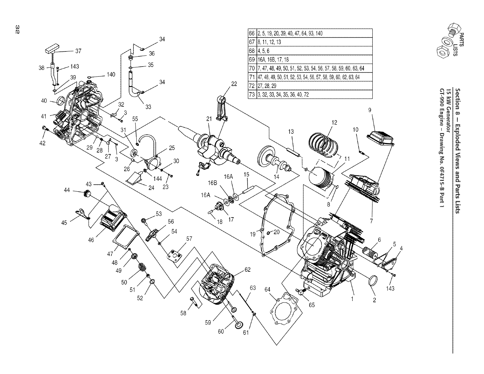
4O
41
42
37
44
45
140
26
46
47
48
49
50
51
52
34
36
35
34
33
22
66 2,5,19,20,39,40,47,64,93,I40
67 8,11,12,13
68 4,5,6
69 16A,16B,17,18
70 7,47,48,49,50,51,52,53,54,56,57,58,59,60,63,64
71 47,48,49,50,51,52,53,54,56,57,58,59,60,62,63,64
72 27,28,29
73 3,32,33,34,35,36,40,72
21
25
23 16B
16A
16A 15
13
14
12
10
58
63 64
\
65
60 61
7
6
143
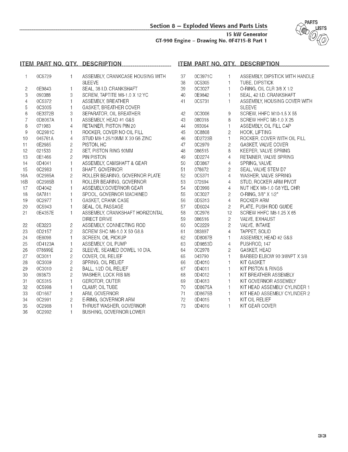
Section 8= E×pIoded Views and Parts Lists
1skw Generator
GT=990 Engine =Drawing No. OF4715=B Part I
F_,_RTtmSTS
iTEM PART NO. QTY.
1 005729 1
2 0E9843 1
3 090388 3
4 0C5372 1
5 0C3005 1
6 0E3372B 3
7 0D8067A 1
8 071983 4
9 0C29810 1
10 045781A 4
11 0E2985 2
12 021533 2
13 0E1486 2
14 0D4041 1
15 002983 1
16A 002985A 2
16B 002985B 1
17 0D4042 1
18 0A7811 1
19 002977 1
20 005943 1
21 0E4357E 1
22 0E3223 2
23 0D2157 2
24 0E6098 1
25 0D4123A 1
26 078699E 2
27 003011 2
28 003009 2
29 0C3010 2
30 093873 2
31 0C5315 1
32 005998 1
33 0D1667 1
34 0C2991 2
35 0C2988 1
36 002992 1
DESCRIP_|QN
ASSEMBLY,CRANKCASEHOUSINGWITH
SLEEVE
SEAL,38 !.D.CRANKSHAFT
SCREW,TAPTITEM6-1.0X 12YC
ASSEMBLY,BREATHER
GASKET,BREATHERCOVER
SEPARATOR,OILBREATHER
ASSEMBLY,HEAD#1 G&S
RETAINER,PISTONPIN20
ROCKER,COVERNOOIL FILL
STUDM8-1.25/10MMX 30 G5 ZINC
PISTON,HO
SET,PISTONRING90MM
PIN PISTON
ASSEMBLY,CAMSHAFT& GEAR
SHAFT,GOVERNOR
ROLLERBEARING,GOVERNORPLATE
ROLLERBEARING,GOVERNOR
ASSEMBLY,GOVERNORGEAR
SPOOL,GOVERNORMACHINED
GASKET,CRANKCASE
SEAL,OILPASSAGE
ASSEMBLY,CRANKSHAFTHORIZONTAL
DIRECTDRIVE
ASSEMBLY,CONNECTINGROD
SCREWSHC M6-1.0X 50 G8.8
SCREEN,OILPICKUP
ASSEMBLY,OIL PUMP
SLEEVE,SEAMEDDOWEL10 DIA.
COVER,OIL RELIEF
SPRING,OIL RELIEF
BALL,1/2DOILRELIEF
WASHER,LOCKRIBM6
GEROTOR,OUTER
CLAMP,OILTUBE
ARM,GOVERNOR
E-RING,GOVERNORARM
THRUSTWASHER,GOVERNOR
BUSHING,GOVERNORLOWER
|YEM PABY NO. QTY. DESCRiPTiON
37 0039710 1 ASSEMBLY,DIPSTICKWITHHANDLE
38 005305 1 TUBE, DIPSTICK
39 003027 1 O-RING,OILCLR3/8X 1/2
40 0E9842 1 SEAL,42 !.D.CRANKSHAFT
41 005731 1 ASSEMBLY,HOUSINGCOVERWITH
SLEEVE
42 003006 9 SCREW,HHFCM10-1.5X 55
43 080318 8 SCREWHHFCM6-1.0X 25
44 093064 1 ASSEMBLY,OILFILL CAP
45 008808 2 HOOK,LIFTING
46 0D2723B 1 ROCKER,COVERWITH OILFILL
47 002979 2 GASKET,\,'AWECOVER
48 086515 8 KEEPER,VALVESPRING
49 0D2274 4 RETAINER,VALVESPRING
50 0D3867 4 SPRING,VALVE
51 078672 2 SEAL,VALVESTEMD7
52 005371 4 WASHER,VALVESPRING
53 072694 4 STUD,ROCKERARM PIVOT
54 0D3998 4 NUT HEXM8-1.0G8YEL CHR
55 003027 2 O-RING,3/8"X 1/2"
56 0D5313 4 ROCKERARM
57 0D8024 2 PLATE,PUSHRODGUIDE
58 0C2976 12 SCREWHHFOM8-1.25X 65
59 086516 2 VALVE,EXHAUST
60 002229 2 VALVE,INTAKE
61 083897 4 TAPPET,SOLID
62 0D8067B 1 ASSEMBLY,HEAD#2 G&S
63 0D9853D 4 PUSHROD,147
64 0C2978 2 GASKET,HEAD
65 043790 1 BARBEDELBOW90 3/8NPTX 3/8
66 0D4010 1 KIT GASKET
67 0D4011 1 KIT PISTON& RINGS
68 0D4012 1 KIT BREATHERASSEMBLY
89 0D4013 1 KIT GOVERNORASSEMBLY
70 0D8875A 1 KIT HEADASSEMBLYCYLINDER1
71 0D8675B 1 KIT HEADASSEMBLYCYLINDER2
72 0D4015 1 KITOIL RELIEF
73 0D4016 1 KIT GEARCOVER
33
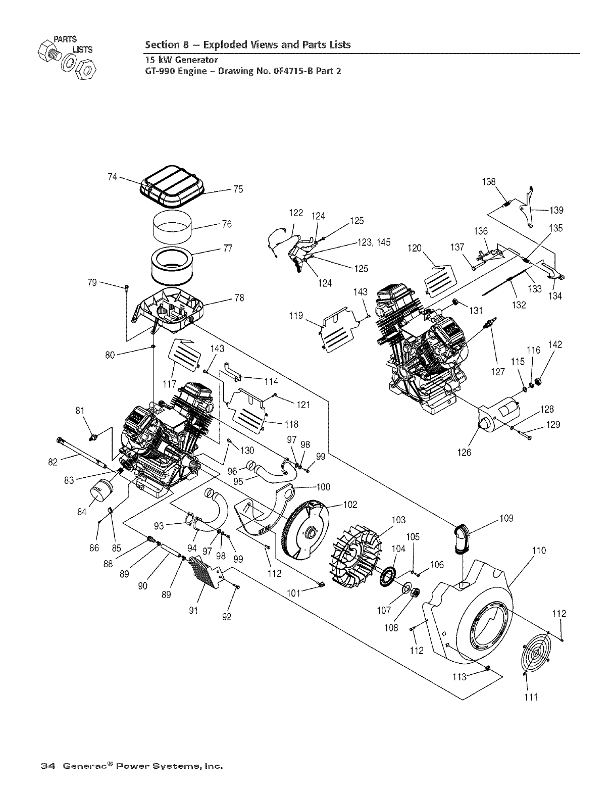
RTSIsTS Section 8 - E×ploded Views and Parts Lists
15 kW Generator
GT=990Engine = Drawing No. 0F4715=BPart 2
122 124 125
123, 145
25
124 143
119__,_
120
138
139
136 _ 135
137
134
132
142
81
1114
128
95
97
126
84
86 85
88 89
90 89
91 92
99
112
103
105
107
108
112
110
112
111
34 GenePac ® Power' SVstems _ Inc,
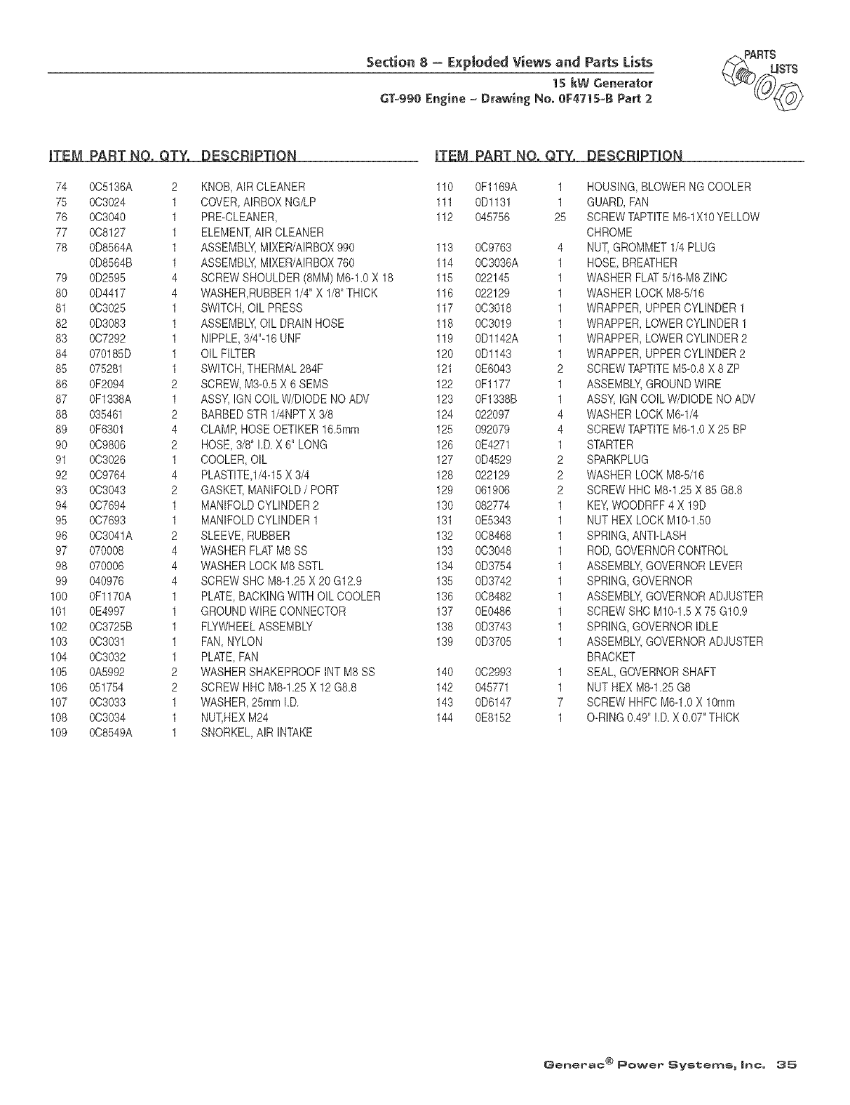
Section 8 - E×ploded Views and Parts Lists
1skw Generator
GT-990 Engine _Drawing No. 0F471S-B Part 2
_)_ RTtmSTS
iTEM PART NO, QTY.
74 0C5138A 2
75 0C3024 1
78 0C3040 1
77 008127 1
78 0D8584A 1
0D8584B 1
79 0D2595 4
80 0D4417 4
81 003025 1
82 0D3083 1
83 0C7292 1
84 070185D 1
85 075281 1
86 0F2094 2
87 0F1338A 1
88 035461 2
89 0F6301 4
90 0C9808 2
91 0C3026 1
92 009764 4
93 0C3043 2
94 0C7694 1
95 0C7893 1
96 003041A 2
97 070008 4
98 070006 4
99 040978 4
100 0F1170A 1
101 0E4997 1
102 003725B 1
103 003031 1
104 0C3032 1
105 0A5992 2
108 051754 2
107 0C3033 1
108 0C3034 1
109 008549A 1
DESCRIPTION
KNOB,AIRCLEANER
COVER,AIRBOXNG/LP
PRE-CLEANER,
ELEMENT,AIR CLEANER
ASSEMBLY,MIXER/AIRBOX990
ASSEMBLY,MIXER/AIRBOX760
SCREWSHOULDER(8MM)M6-1.0X 18
WASHER,RUBBER1/4"X 1/8"THICK
SWITCH,OIL PRESS
ASSEMBLY,OIL DRAINHOSE
NIPPLE,3/4"-16UNF
OILFILTER
SWITCH,THERMAL284F
SCREW,M3-0.5X 8 SEMS
ASSY,IGNCOiLW/DIODENOADV
BARBEDSTR 1/4NPTX 3/8
CLAMP,HOSEOETIKER16.5mm
HOSE,3/8" I.D.X 6" LONG
COOLER,OIL
PLASTITE,1/4-15X 3/4
GASKET,MANIFOLD/PORT
MANIFOLDCYLINDER2
MANIFOLDCYLINDER1
SLEEVE,RUBBER
WASHERFLATM8SS
WASHERLOCK M8SSTL
SCREWSHC M8-1.25X 20G12.9
PLATE,BACKINGWITHOILCOOLER
GROUNDWIRECONNECTOR
FLYWHEELASSEMBLY
FAN,NYLON
PLATE,FAN
WASHERSHAKEPROOFINTM8SS
SCREWHHCM8-1.25X 12G8.8
WASHER,25mmI.D.
NUT,HEX M24
SNORKEL,AIR INTAKE
ITEM PART NO, QTY.
110 0F1169A 1
111 0Dl131 1
112 045758 25
113 009783 4
114 003036A 1
115 022145 1
116 022129 1
117 0C3018 1
118 003019 1
119 0D1142A 1
120 0Dl143 1
121 0E8043 2
122 0Fl177 1
123 0F1338B 1
124 022097 4
125 092079 4
128 0E4271 1
127 0D4529 2
128 022129 2
129 061906 2
130 082774 1
131 0E5343 1
132 008488 1
133 003048 1
134 0D3754 1
135 0D3742 1
136 0C8482 1
137 0E0488 1
138 0D3743 1
139 0D3705 1
140 0C2993 1
142 045771 1
143 0D6147 7
144 0E8152 1
DESCRIPTION
HOUSING,BLOWERNGCOOLER
GUARD,PAN
SCREWTAPTITEM8-1Xl0YELLOW
CHROME
NUT,GROMMET1/4PLUG
HOSE,BREATHER
WASHERFLAT5/16-M8ZINC
WASHERLOCKM8-5/16
WRAPPER,UPPERCYLINDER1
WRAPPER,LOWERCYLINDER1
WRAPPER,LOWERCYLINDER2
WRAPPER,UPPERCYLINDER2
SCREWTAPTITEM5-0.8X 8 ZP
ASSEMBLY,GROUNDWIRE
ASSY,IGNCOILW/DIODENOADV
WASHERLOCKM8-1/4
SCREWTAPTITEM6-1.0X 25 BP
STARTER
SPARKPLUG
WASHERLOCKM8-5/16
SCREWHHCM8-1.25X 85 G8.8
KEY,WOODRFF4 X 19D
NUT HEXLOCKM10-1.50
SPRING,ANTI-LASH
ROD,GOVERNORCONTROL
ASSEMBLY,GOVERNORLEVER
SPRING,GOVERNOR
ASSEMBLY,GOVERNORADJUSTER
SCREWSHC M10-1.5X 75G10.9
SPRING,GOVERNORIDLE
ASSEMBLY,GOVERNORADJUSTER
BRACKET
SEAL,GOVERNORSHAFT
NUT HEXM8-1.25G8
SCREWHHFCM6-1.0X 10mm
O-RING0.49"I.D.X 0.07"THICK
Generac ®Power' Systems_ mnc, 35
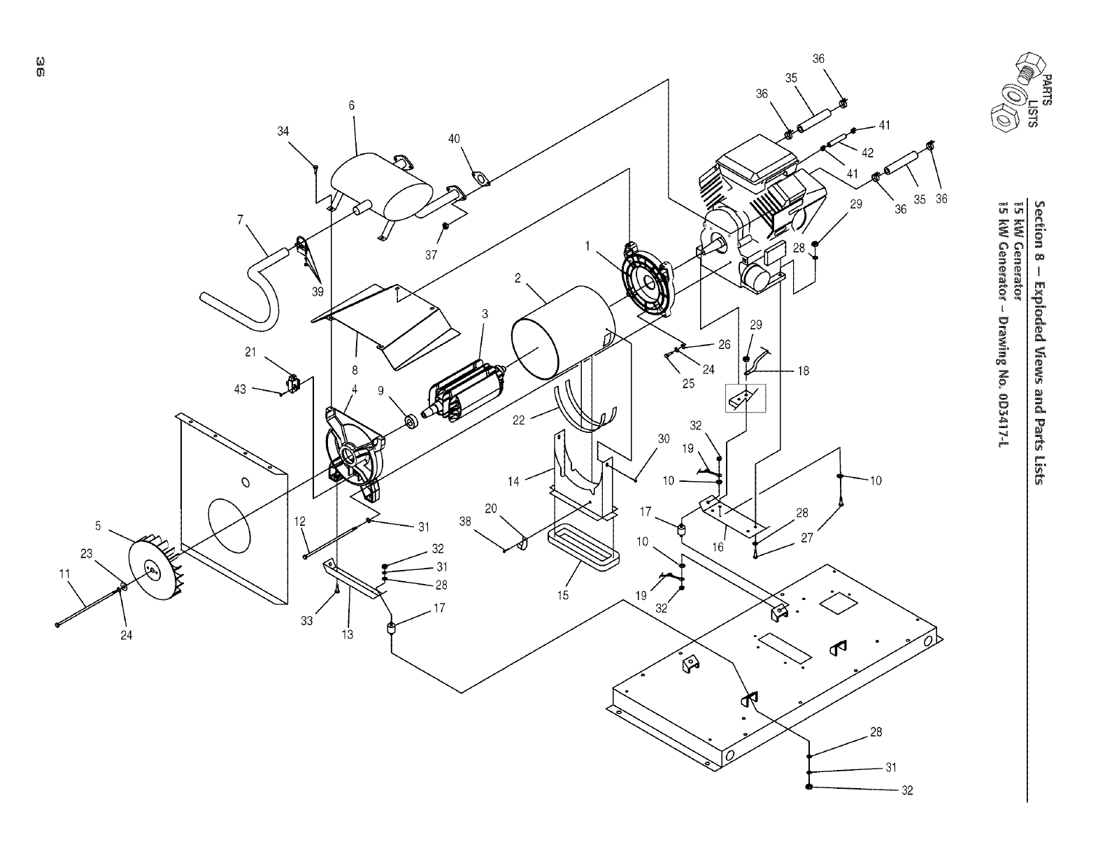
34 40
36
36
35
11
5
23
24
21
43
33
13
37
8
9
31
32
28
2
3
20
38
15
\
30
17
10
32
25
32
19\
26
16
29
28
27
35 36
36
31
32
H
6'€
Z
o
0
t#
¢0
x
E
&
##
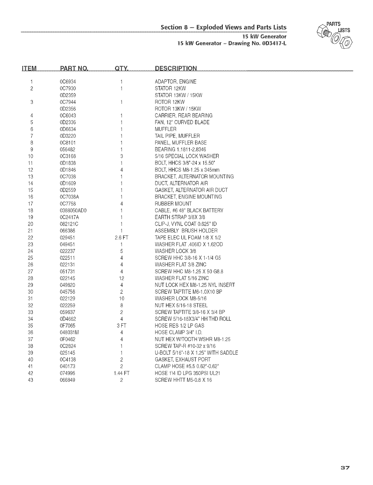
Section 8- E×pIoded Views and Parts Lists
15 kW Generator
15 kW Generator =Drawing No. 0D3417=L
'_(_ _RTtISTS
iTEM
4
5
6
7
8
9
10
11
12
13
14
15
16
17
18
19
2O
21
22
23
24
25
26
27
28
29
3O
31
32
33
34
35
36
37
38
39
40
41
42
43
PART NO.
0C6934
007930
0D2359
0C7944
0D2356
006043
0D2336
0D6634
0D3220
008101
056482
003168
0D1838
0D1846
007038
0D1609
0D2559
007038A
007758
0388050AD0
002417A
082121C
066386
029451
049451
022237
022511
022131
051731
022145
049820
045756
022129
022259
059637
0D4662
0F7065
048031M
0F0462
002824
025145
004138
040173
074995
066849
QTY', DESCRIPTION
1
1
1
1
1
1
3
1
4
1
1
1
1
4
1
1
1
1
2.6 FT
1
5
4
4
4
12
4
2
10
8
2
4
3 FT
4
4
1
1
2
2
1.44FT
2
ADAPTOR,ENGINE
STATOR12KW
STATOR13KW/15KW
ROTOR12KW
ROTOR13KW/15KW
CARRIER,REARBEARING
FAN,12" CURVEDBLADE
MUFFLER
TAILPIPE, MUFFLER
PANEL,MUFFLERBASE
BEARING1.1811-2.8346
5/16 SPECIALLOCKWASHER
BOLT,HHCS3/8"-24x 15.50"
BOLT,HHCS M8-1.25x 345mm
BRACKET,ALTERNATORMOUNTING
DUCT,ALTERNATORAIR
GASKET,ALTERNATORAIR DUCT
BRACKET,ENGINEMOUNTING
RUBBERMOUNT
CABLE,#6 48" BLACKBATTERY
EARTHSTRAP3/8X 3/8
CLIP-J,VYNLCOAT0.625"ID
ASSEMBLYBRUSHHOLDER
TAPEELECULFOAM1/8X 1/2
WASHERFLAT.4061DX 1.62OD
WASHERLOCK3/8
SCREWHHC3/8-16 X 1-1/4G5
WASHERFLAT3/8ZINC
SCREWHHC M8-1.25X 50 G8.8
WASHERFLAT5/16ZINC
NUT LOCKHEX M8-1.25NYL INSERT
SCREWTAPTITEM6-1.0X10BP
WASHERLOCKM8-5/16
NUT HEX5/16-18STEEL
SCREWTAPTITE3/8-16X 3/4BP
SCREW5/16-18X3/4"HHTHD ROLL
HOSE RES1/2 LP GAS
HOSE CLAMP3/4" I.D.
NUT HEXW/TOOTHWSHRM8-1.25
SCREWTAP-R#10-32x 9/16
U-BOLT5/16"-18X 1.25"WITHSADDLE
GASKET,EXHAUSTPORT
CLAMPHOSE#5.5 0.62"-0.62"
HOSE 1\4 ID LPG350PSIUL21
SCREWHHTTM5-0.8X 16
37
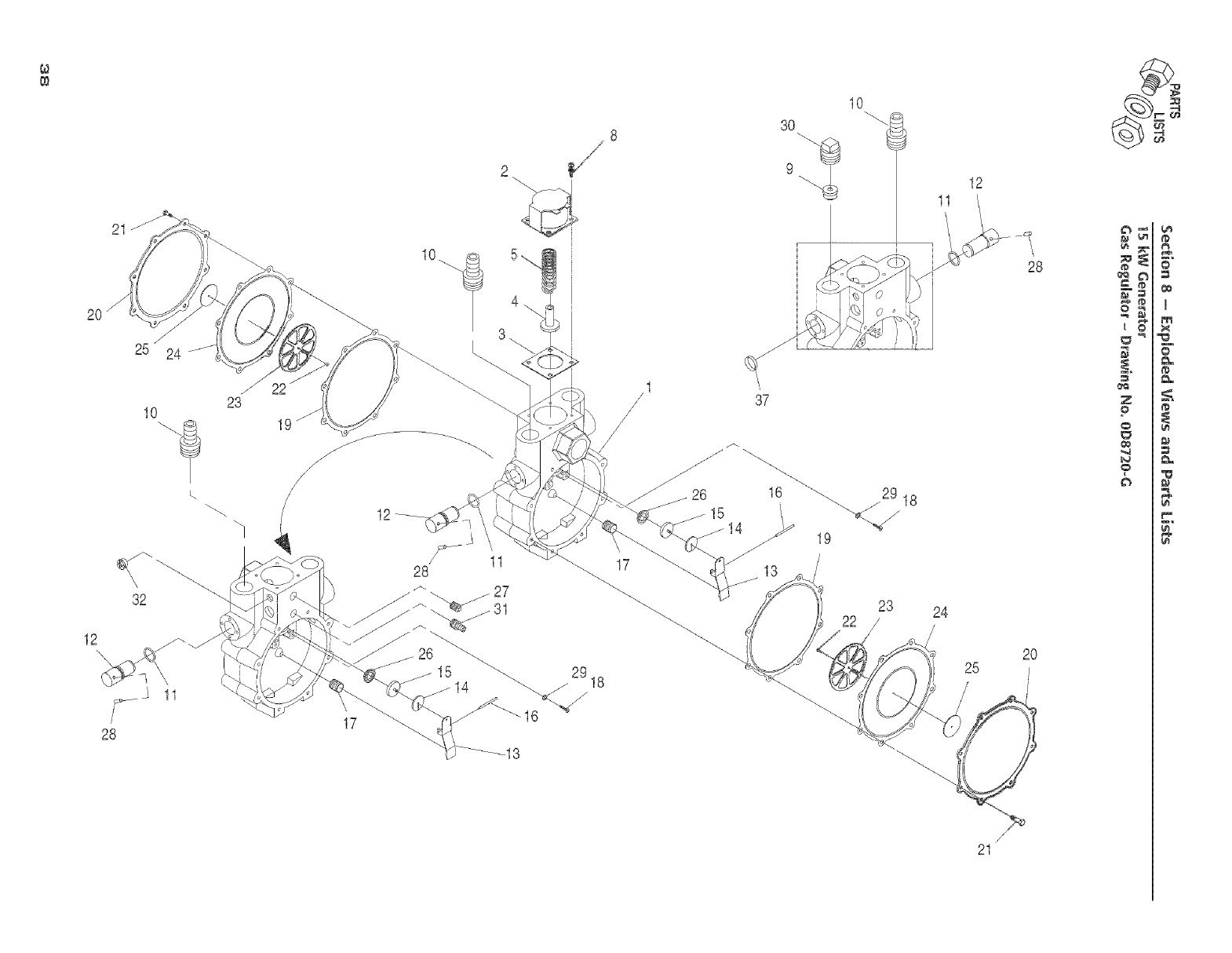
20
./
25 24
23
10
12
J
/
/
/
17
12
8
2
10_
3
10
30 "0
J
\
37
J_
J26 16 _ 29
_14 19
13
23
11
24
12
25
28
2O
z _
o _
?
/
21
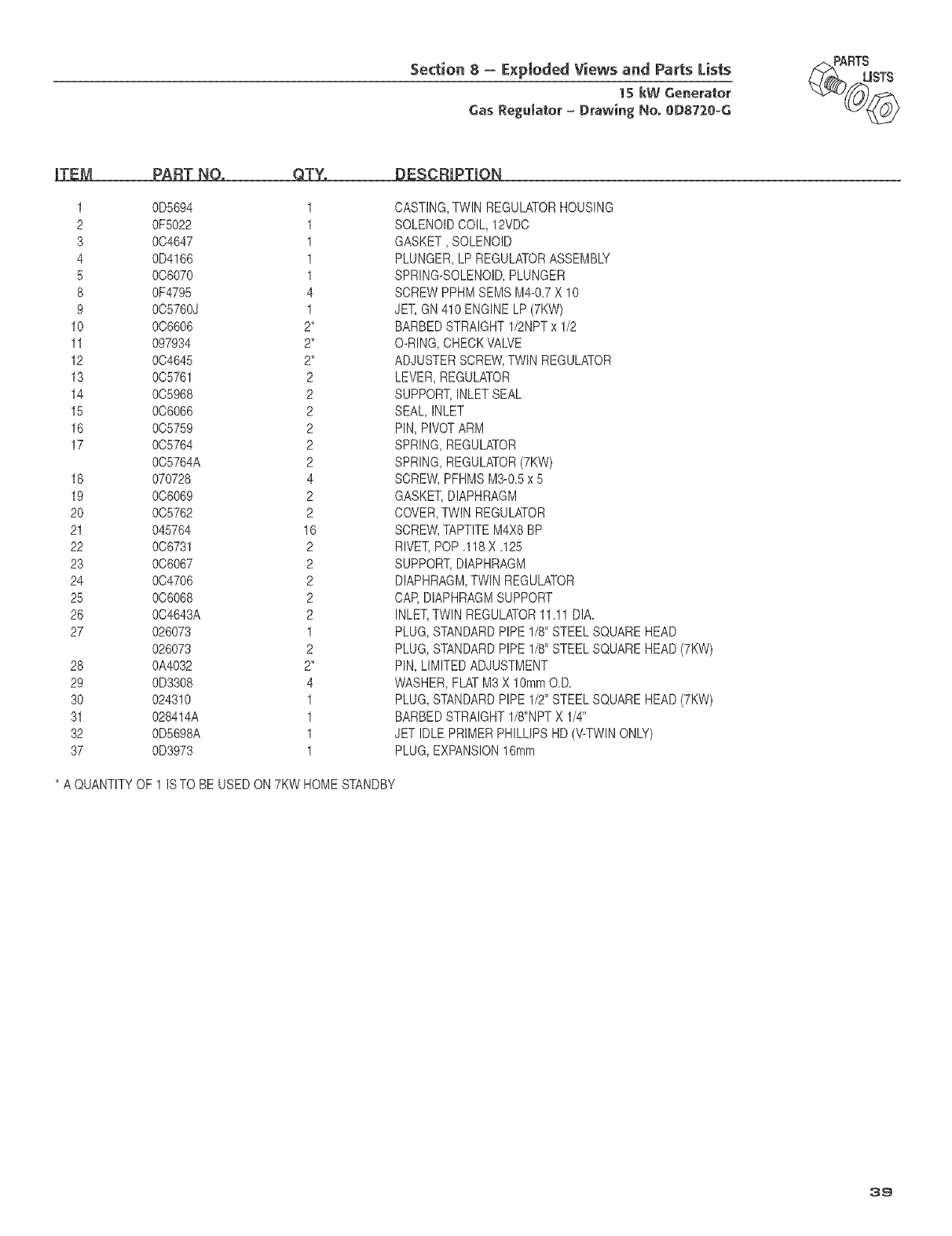
Section 8 - E×ploded Views and Parts Lists
1S kW Generator
Gas Regumator= Drawing No. OD8720=G
_(_ RTtmSTS
iTEM PART NO, QTY.
1 0D5694
2 0F5022
3 004647
4 0D4166
5 006070
8 0F4795
9 005760J
10 006606
11 097934
12 004645
13 005761
14 005968
15 006066
16 005759
17 005764
005764A
18 070728
19 006069
20 005762
21 045764
22 006731
23 006067
24 0C4706
25 0C6068
26 004643A
27 026073
026073
28 0A4032
29 0D3308
30 024310
31 028414A
32 0D5698A
37 0D3973
1
1
1
1
1
4
1
2*
2*
2*
2
2
2
2
2
2
* A QUANTITYOF 1 ISTO BE USEDON 7KW
DESCRIPTION
4
2
2
16
2
2
2
2
2
1
2
2*
4
1
1
1
1
CASTING,TWIN REGULATORHOUSING
SOLENOIDCOIL, 12VDC
GASKET, SOLENOID
PLUNGER,LP REGULATORASSEMBLY
SPRING-SOLENOID,PLUNGER
SCREWPPHMSEMS M4-0.7X 10
JET,GN410 ENGINELP (7KW)
BARBEDSTRAIGHT1/2NPTx 1/2
O-RING,CHECKVALVE
ADJUSTERSCREW,TWINREGULATOR
LEVER,REGULATOR
SUPPORT,INLETSEAL
SEAL, INLET
PIN, PIVOTARM
SPRING,REGULATOR
SPRING,REGULATOR(7KW)
SCREW,PFHMSM3-0.5x 5
GASKET,DIAPHRAGM
COVER,TWIN REGULATOR
SCREW,TAPTITEM4X8BP
RIVET,POP .118X.125
SUPPORT,DIAPHRAGM
DIAPHRAGM,TWIN REGULATOR
CAP,DIAPHRAGMSUPPORT
INLET,TWINREGULATOR11.11DIA.
PLUG,STANDARDPIPE1/8"STEELSQUAREHEAD
PLUG,STANDARDPIPE1/8"STEELSQUAREHEAD(7KW)
PIN, LIMITEDADJUSTMENT
WASHER,FLATM3X 10ramO.D.
PLUG,STANDARDPIPE1/2"STEELSQUAREHEAD(7KW)
BARBEDSTRAIGHT1/8"NPTX 1/4"
JET IDLEPRIMERPHILLIPSHD (\,'-TWINONLY)
PLUG,EXPANSION16ram
HOMESTANDBY
39
Section 9 - Warranty
15 kW Generator
NOTE: This Emission Control Warranty Statement pertains to this product only IF the generator size is 15 kW or below.
CALiFORNiA AND FEDERALEMiSSiONCONTROLWARRANTYSTATEMENT
YOURWARRANTYRIGHTSAND OBLIGATIONS
The California Air Resources Board (CARB) and the United States Environmental Protection Agency (EPA), together with
Generac Power Systems, Inc. (Generac), are pleased to explain the Emission Control System Warranty on your new' engine.*
New (small off road) engines must be designed, built and equipped to meet stringent anti-smog standards for the state of
California and the federal government. Generac will warrant the emission control system on your engine for the periods of
time listed below provided there has been no abuse, neglect, unapproved modification or improper maintenance of your
engine.
Your emission control system may include parts such as the carburetor, ignition and exhaust systems. Generac will repair your
engine at no cost to you for diagnosis, replacement parts and labor_ should a warrantable condition occur.
MANUFACTURER'S EMISSION CONTROL SYSTEM WARRANTY COVERAGE:
Emissions control systems on engines are warranted for two years as hereinafter noted, if, during such warranty period,
any emission-rebted component or system on your engine is found to be defective in materiaB or workmanship, repairs or
repbcement will be performed by a Generac Authorized Warranty Service Facility.
PURCNASER'SIOWNER'S WARRANTY RESPONSIBILITIES:
As the engine purchaser/owners you are responsible for the completion of all required maintenance as listed in your factory
supplied Owner's Manual For warranty purposes, Generac recommends that you retain all receipts covering maintenance on
your engine. However; Generac cannot deny warranty solely because of the lack of receipts or for your failure to ensure the
completion of all scheduled maintenance.
As the engine purchaser/owners you should, however} be aware that Generac may deny any and/or all warranty coverage or
responsibility if your engine, or a part!component thereof, has failed due to abuse, neglect, improper maintenance or unap-
proved modifications, or the use of counterfeit and/or "grey market" parts not made, supplied or approved by Generac.
You are responsible for presenting your engine to a Generac Authorized Warranty Service Fadlity as soon as a
prebJem occurs° The warranty repairs should be completed in a reasonable amount of time, not to exceed 30 days.
Warranty service can be arranged by contacting either your selling dealer or a Generac Authorized Warranty, Service Facility.
To locate the Generac Authorized Warranty Service Facility nearest you, call our tolPfree number:
1-800-333-1322
iMPORTANT NOTE: This warranty statement explains your rights and obligations under the Emission Control System Warranty
(ECS Warranty), which is provided to you by Generac pursuant to California and federal law. See also the "Generac Limited
Warranties for Generac Power Systems, Inc," which is enclosed herewith on a separate sheet, also provided to you by Generac.
The ECS Warranty applies only to the emission control system of your new' engine. If there is any conflict in terms between the
ECS Warranty and the Generac Warranty,, the ECS Warranty shall apply except in circumstances where the Generac Warranty
may provide a longer warranty period. Both the ECS Warranty and the Generac Warranty describe important rights and obli-
gations with respect to your new engine.
Warranty service can be performed only by a Generac Authorized Warranty Service Facility. When requesting warranty ser-
vice, evidence must be presented showing the date of the sale to the original purchaser/owner. The purchaser/owner shall
be responsible for any expenses or other charges incurred for service calls and/or transportation of the product to!from the
inspection or repair facilities. The purchaser!owner also shall be responsible for any and/or all damages or losses incurred while
the engine is being transported/shipped for inspection or warranty repairs.
if you have any questions regarding your warranty rights and responsibilities, you should contact Generac at
the followingaddress:
ATTENTIONWARRANTYDEPARTMENT
GENERACPOWERSYSTEMS,INC.
P.O.BOX297
WHITEWATER,WI53190
Part 1
40
Section 9 - Warranty
15 kW Generator
EMISSION CONTROL SYSTEM WARRANTY
Emission Control System Warranty (ECS Warranty) for 1997 and later model year engines:
(a) Applicability: This warranty shall apply to 1997 and later model year engines. The ECS Warranty Period shall begin on the
date the new engine or equipment is purchased by/delivered to its original, end-use purchaser/owner and shall continue for
24 consecutive months thereafter.
(b) General Emissions Warranty Coverage: Generac warrants to the original, end-use purchaser/owner of the new engine or
equipment, and to each subsequent purchaser/owner, that each of its engines is ._
(1) Designed, built and equipped so as to conform with all applicable regulations adopted by the EPA and CARB pursuant to
their respective authority, and
(2) Free from defects in materials and workmanship which, at any time during the ECS Warranty Period, may cause a war-
ranted emissionsorelated part to fail to be identical in all material respects to the part as described in the engine manufac-
turer's application for certification.
(c) The ECS Warranty only pertains to emissions°related parts on your engine, as follows:
(1) Any warranted, emissionsorelated parts that are not scheduled for replacement as required maintenance in the Owners
Manual shall be warranted for the ECS Warranty Period. If any such part fails during the ECS Warranty Period, it shall
be repaired or replaced by Generac according to Subsection (4) below. Any such part repaired or replaced under the EC5
Warranty shall be warranted for the remainder of the ECS Warranty Period.
(2) Any warranted, emissions-related part that is scheduled only for regular inspection as specified in the Owners Manual
shall be warranted for the ECS Warranty Period. A statement in such written instructions to the effect of "repair or replace
as necessary" shall not reduce the ECS Warranty Period. Any such part repaired or replaced under the ECS Warranty shall
be warranted for the remainder of the ECS Warranty Period.
(3) Any warranted, emissionsorelated part that is scheduled for replacement as required maintenance in the Owner's Manuai
shall be warranted for the period of time prior to the first scheduled replacement point for that part. if the part fails prior
to the first scheduled replacement0 the part shall be repaired or replaced by Generac according to Subsection (4) below.
Any such emissionsorelated part repaired or replaced under the ECS Warranty shall be warranted for the remainder of the
ECS Warranty Period prior to the first scheduled replacement point for such emissionsorelated part.
(4) Repair or replacement of any warranted, emissionsorelated part under this ECS Warranty shall be performed at no charge
to the owner at a Generac Authorized Warranty Service Facility.
(5) When the engine is inspected by a Generac Authorized Warranty Service Facility, the owner shall not be held responsible
for diagnostic costs if the repair is deemed warrantable.
(6) Generac shall be liable for damages to other original engine components or approved modifications proximately caused
by a failure under warranty of any emission-related part covered by the ECS Warranty.
(7) Throughout the ECS Warranty Period, Generac shall maintain a supply of warranted emission-related parts sufficient to
meet the expected demand for such emission-related parts.
(8) Any Generac authorized and approved emission-related replacement part may be used in the performance of any ECS
Warranty maintenance or repairs and wiil be provided without charge to the purchaser/owner. Such use shall not reduce
Generac's ECS Warranty obligations.
(9) Unapproved, add-on, modified, counterfeit and/or "grey market" parts may not be used to modify or repair a Generac
engine. Such use voids this ECS Warranty and shall be sufficient grounds for disallowing an ECS Warranty claim. Generac
shall not be held liable hereunder for failures of any warranted parts of a Generac engine caused by the use of such an
unapproved, add-on, modified, counterfeit and/or "grey market" part.
EMISSION RELATED PARTS INCLUDE THE FOLLOWING:
1) Fuel Metering System:
1.1) Gasoline carburetor assembly and its
internal components (if so equipped).
a) Fuel filter (if so equipped)
b) Carburetor gaskets
c) Fuel pump (if so equipped)
1.2) LPG carburetion assembly and its
internal components (if so equipped).
a) Fuel controller (if so equipped)
b) Mixer and its gaskets (if so equipped)
c) Carburetor and its gaskets (if so equipped)
d) Primary gas regulator (if so equipped)
e) LP liquid vaporizer (if so equipped)
2) Air Induction System including:
a) Intake pipe/manifold
b) Air cleaner
3) Ignition System including:
a) Spark plug
b) Ignition module
4) Catalytic Muffler Assembly (if so equipped) including:
a) Muffler gasket
b) Exhaust manifold
5) Crankcase Breather Assembly including:
a) Breather connection tube
*Generac engine types covered by this warranty statement include the following:
1) Utility
2) Lawn and Garden Equipment
3) Recreational Vehicle (RV) Generator
4) Industrial Mobile 0M) Generator
Part 2
41
Section 9-Warranty
1S kW Generator
CARRIER "TWO YEAR" LIMITED WAR_NTY FOR
"PREPACKAGED EMERGENCY AUTOMATIC STANDBY GENEPJ_TORS"
For a period of two years from the date of original sale, Carrier warrants that its generator will be free from defects in material and
workmanship for the items and period set forth below. Carrier will, at its option, repair or replace any part which, upon examination,
inspection and testing by' a Carrier Dealer, is found to be defective. AiI transportation costs under the warranty, including return to the
factory, are to be borne and prepaid by the purchaser/owner. This warranty applies only to Carrier prepackaged emergency automatic
standby generators sold and rated for use in "Standby" applications.
WARRANTY SCHEDULE
YEARS ONE AND TWO - 100% (one hundred percent) transferable coverage on Labor and Part(s) listed.
ENGINE - All Components
ALTERNATOR - All Components
TRANSFER SYSTEM - AII Components
Steel enclosures are warranted against rusting for the first year of ownership only. Damage caused after receipt of generator is the
responsibility of the owner and is not covered by this warranty. Nicks, scrapes, dents or scratches to the painted enclosure should be
repaired promptly by the owner.
THiS WARRANTY SHALL NOT APPLY TO THE FOLLOWING:
Carrier generators that utilize non-Carrier replacement parts.
Carrier generators utilizing non-Carrier automatic transfer switches.
Any Carrier generators used as rental or trailer mounted appiications.
Units used for prime power in place of existing utility power where utility power is present or in place of utility power where utility
power service does not normally exist.
Costs of normal maintenance, adiustments, instailation and start-up.
Steel enclosures that are rusting due to the improper installation, location in a harsh or saltwater environment or scratched where
integrity of paint applied is compromised.
Failures caused by any contaminated fuels, oils, cootants or Iack of proper fluid amounts.
Failures due, but not limited to, accident, misuse, abuse, negligence or improper instailation. As with all mechanicaI devices, the
Carrier engines need periodic part(s) service and replacement to perform wetL
Failures caused by any externat cause or act of God, such as collision, theft, vandaiism, riot or wars, nuclear holocaust, fire,
freezing, lightning, earthquake, windstorm, hail, volcanic eruption, water or flood, tornado or hurricane.
Damage related to rodent and/or insect infestation.
Products that are modified or altered in a manner not authorized by Carrier in writing.
Any incidental, consequential or indirect damages caused by defects in materials or workmanship, or any delay in repair or
replacement of the defective part(s).
Failure due to misapplication.
Telephone, cellular phone, facsimile, internet access or other communication expenses.
Living or travel expenses of person(s) performing service, except as specifically included within the terms of a specific unit warranty
period.
Expenses related to "customer instruction" or troubleshooting where no manufacturing defect is found.
Rental equipment used while warranty repairs are being performed.
Costs incurred for equipment used for removal and/or reinstallation of generator, (ke.; cranes, hoists, lifts, etc.)
Overnight freight costs for replacement part(s).
Overtime labor.
Starting batteries, fuses, light bulbs and engine fluids.
rHIS WARRANTY IS IN PLACE OF ALL OTHER WARRANTIES, EXPRESSED OR IMPLIED. SPECIFICALLY,
CARRIER MAKES NO OTHER WARRANTIES AS TO THE MERCHANTABiLiTY OR FITNESS FOR A PARTICULAR PURPOSE.
Some states do not allow limitations on how long an implied warranty lasts, so the above limitation may not apply to you.
CARRIER'S ONLY LiABiLiTY SHALL BE THE REPAIR OR REPLACEMENT OF PART(S) AS STATED ABOVE. IN NO EVENT
SHALL CARRIER BE LIABLE FOR ANY iNCiDENTAL OR CONSEQUENTIAL DAMAGES, EVEN iF SUCH DAMAGES ARE A
DIRECT RESULT OF CARRIER'S NEGLIGENCE. Some states do not allow the exclusion or limitation of incidental or consequential
damages, so the above limitation may not apply to you.
This warranty gives you specific legal rights. You also have other rights from state to state.
Revision (10/01/04)
Part No. 0F7551 Rev. 0 (08/24/05) Catalog No. OMASPAXI5ol Printed in U.S,A,
