CARRIER Package Units(both Units Combined) Manual L0520543
User Manual: CARRIER CARRIER Package Units(both units combined) Manual CARRIER Package Units(both units combined) Owner's Manual, CARRIER Package Units(both units combined) installation guides
Open the PDF directly: View PDF ![]() .
.
Page Count: 62
48HJD/HJE008-014
48HJ F008-012
Single-Package Rooftop
Gas Heating/Electric Cooling Units
Installation, Start-Up and
Service Instructions
CONTENTS
Page
SAFETY CONSIDERATIONS ...................... 1
INSTALLATION ................................ 1-41
Step 1 -- Provide Unit Support ................... 2
• ROOF CURB
• SLAB MOUNT
• ALTERNATE UNIT SUPPORT
Step 2 -- Field Fabricate Ductwork ............... 2
Step 3 -- Determine Location of Drain Line
and External Trap .............................. 2
Step 4 -- Rig and Place Unit ..................... 4
• POSITIONING
Step 5 -- Install Flue Hood ....................... 4
Step 6-- Install Gas Piping ...................... 4
Step 7 -- Make Electrical Connections ........... 9
• FIELD POWER SUPPLY
• FIELD CONTROL WIRING
• HEAT ANTICIPATOR SETTINGS
Step 8-- Adjust Factory-Installed Options ...... 10
• HUMIDI-MIZER TM DEHUMIDIFICATION
SYSTEM
• CONVENIENCE OUTLET
• NOVAR CONTROLS
• MANUAL OUTDOOR-AIR DAMPER
• PREMIERLINK r_'_CONTROL
• OPTIONAL ECONOMISER IV AND ECONOMISER2
• ECONOMI$ER IV STANDARD SENSORS
• ECONOMI$ER IV CONTROL MODES
Step 9 -- Adjust Evaporator-Fan Speed ......... 25
PRE-START-UP .................................. 42
START-UP .................................... 42-47
SERVICE ..................................... 47-53
TROUBLESHOOTING ......................... 54-59
INDEX ........................................... 60
START-UP CHECKLIST ........................ CL-I
SAFETY CONSIDERATIONS
Installation and sel-,Ticingof air-conditioning equipment can
be hazardous due to system pressure and electrical compo-
nents. Only trained and qualified service personnel should
install, repair, or service ai>conditioning equipment.
Untrained personnel can perform basic maintenance func-
tions of cleaning coils and filters and replacing filters. All other
operations should be performed by trained service personnel.
When working on ai>conditioning equipment, observe precau-
tions in the literature, tags and labels attached to the unit, and
other safety precautions that may apply.
Follow all safety codes. Wear safety glasses and work
gloves. Use quenching cloth for unbrazing operations. Have
fire extinguishers available for all brazing operations.
Ensum voltage listed on unit data plate agmes with electri-
c_dsupply provided for the unit.
Disconnect gas piping fi_m unit when leak
testing at pressure greater than I/2 psig. Pms-
sums greater than ]12psig will cause gas valve
damage resulting in haz_u'dous condition. If
gas valve is subjected to pressure greater than
1/2 psig, it must be replaced before use. When
_ressure testing field-supplied gas piping at
?ressures of 1/2 psig or less, a unit connected to
;uch piping must be isolated by manu_dlyclos-
ing the gas valve(s).
Before performing service or maintenance operations on
unit, turn off main power switch to unit. Electrical shock
could cause personal injury.
INSTALLATION
Unit is shipped in the vertical configuration. To convert to
horizont_flapplication, remove side duct opening covers. Using
the same scmws, install coveLs on vertical duct openings with
the insulation-side down. Seals around duct openings must be
tight. See Fig. 1.
Step 1 -- Provide Unit Support
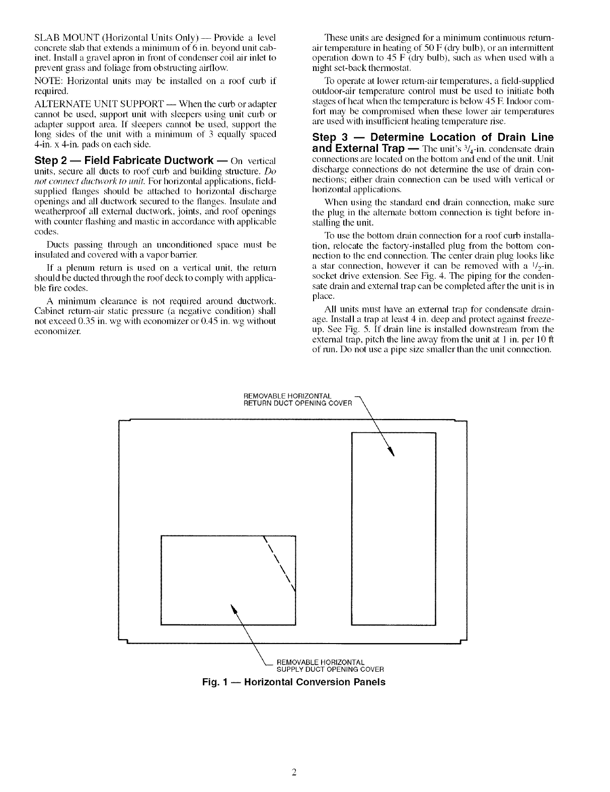
ROOF CURB -- Assemble and install accesso Uroof curb in
accor&mce with instructions shipped with curb. See Fig. 2.
Install insulation, cant strips, roofing felt, and counter flashing
as shown. Ductwork must be attached to curb. If electric or
control power is to be routed through the basepan, attach the
accessory thru-the-bottom service connections to the basepan
in accordance with the accessory installation instructions. Con-
nections must be installed befom unit is set on roof curb.
IIMPORTANT: The gasketing of the unit to the roof curb is I
critical for a watertight seal. Install gasket supplied with the I
roof curb as shown in Fig. 2. hnproperly applied gasket can
also result in air leaks and poor unit performance.
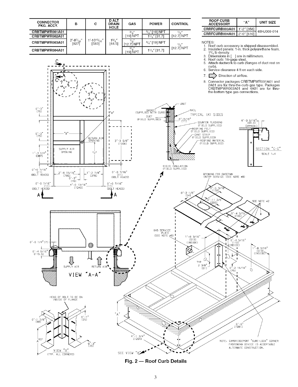
Curb should be level. This is necessary for unit drain to
function properly. Unit leveling tolerances am shown in Fig. 3.
Refer to Accessory Roof Curb Installation Instructions for
additional infomtation as requimd.
Manufacturer reserves the right to discontinue, or change at any time, specifications or designs without notice and without incurring obligations.
Catalog No. 04-53480012-01 Printed in U,S.A, Form 48HJ-32SI Pg 1 9-05 Replaces: 48HJ-28SI
SLAB MOUNT (Horizontal Units Only) -- Provide a level
concrete slab that extends a minimum of 6 in. beyond unit cab-
inet. Install a gravel apron in front of condenser coil air inlet to
plevent grass and foliage from obstructing airflow.
NOTE: Horizontal units may be installed on a roof curb if
required.
ALTERNATE UNIT SUPPORT -- When the curb or adapter
cannot be used, support unit with sleepers using unit curb or
adapter support alea. If sleepel_ cannot be used, support the
long sides of the unit with a minimum of 3 equally spaced
4-in. x 4-in. pads on each side.
Step 2 -- Field Fabricate Ductwork -- On vertical
units, secure all ducts to roof curb and building structure. Do
not connect duct_'ork to unit. For horizont_fl applications, field-
supplied flanges should be attached to horizontal discharge
openings and all ductwoN secured to the flanges. Insulate and
weatherproof all external ductwork, joints, and roof openings
with counter flashing and mastic in accordance with applicable
codes.
Ducts passing through an unconditioned space must be
insulated and covered with a vapor b_uriel:
If a plenum return is used on a vertical unit, the return
should be ducted through the roof deck to comply with applica-
ble fire codes.
A minimum clearance is not requiled around ductwork.
Cabinet return-air static pressure (a negative condition) shall
not exceed 0.35 in. wg with economizer or 0.45 in. wg without
economizel:
These units are designed for a minimum continuous return-
air temperature in heating of 50 F (c_h_bulb), or an intermittent
operation down to 45 F (r_h_ bulb), such as when used with a
night set-back thermostat.
To operate at lower return-air temperatures, a field-supplied
outdoor-air temperature control must be used to initiate both
stages of heat when the temperature is below 45 E Indoor com-
fort may be compromised when these lower air temperatures
are used with insufficient heating temperature rise.
Step 3 -- Determine Location of Drain Line
and External Trap -- The unit's 3/4-in. condensate &ain
connections are located on the bottom and end of the unit. Unit
discharge connections do not determine the use of c_h'aincon-
nections; either c_h'ainconnection can be used with vertical or
horizontal applications.
When using the standard end c_h'_dnconnection, make sure
the plug in the alternate bottom connection is tight before in-
stalling the unit.
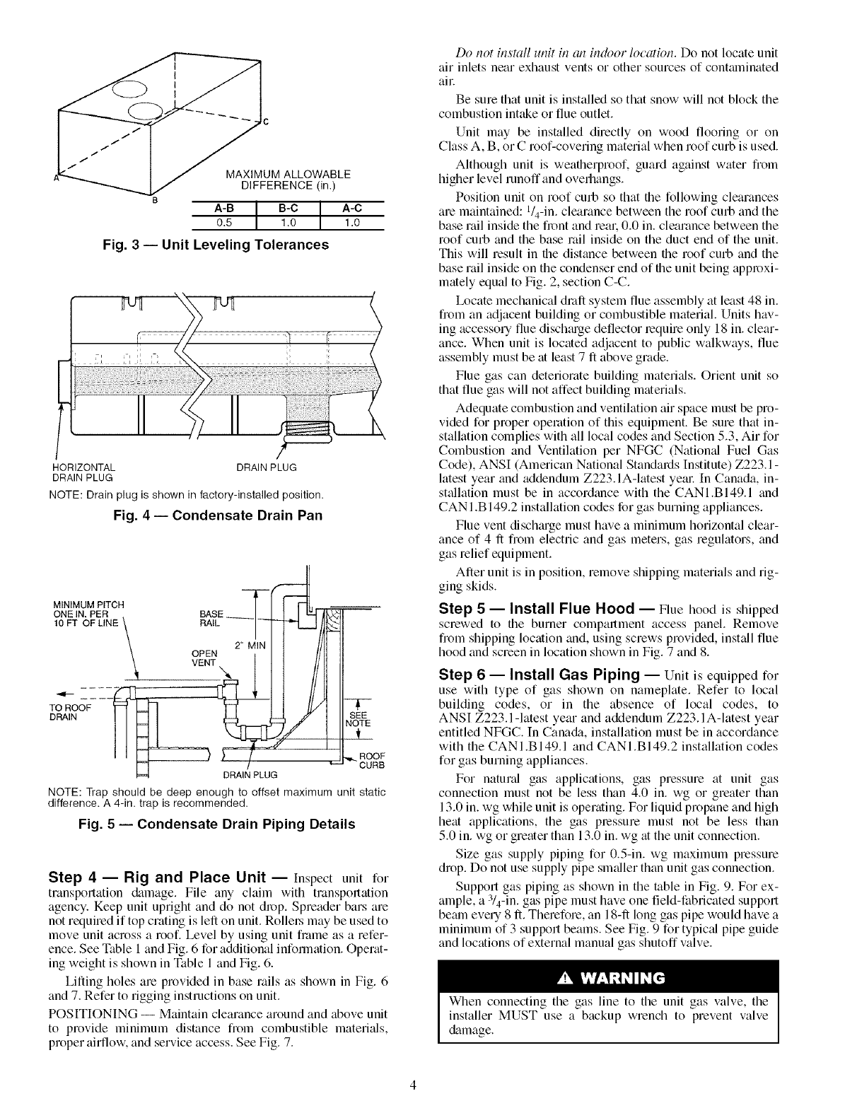
To use the bottom drain connection for a roof curb installa-
tion, lelocate the factory-installed plug from the bottom con-
nection to the end connection. The center c_hainplug looks like
a star connection, however it can be removed with a l/2-in.
socket c_hive extension. See Fig. 4. The piping for the conden-
sate c_h'ainand external trap can be completed after the unit is in
place.
All units must have an extern_fl trap for condensate &'ain-
age. Inst_dl a trap at least 4 in. deep and protect against freeze-
up. See Fig. 5. If drain line is installed downsheam from the
extern_fl trap, pitch the line away from the unit at 1 in. per 10 ft
of run. Do not use a pipe size smaller than the unit connection.
REMOVABLE HORIZONTAL
RETURN DUCT OPENING COVER \\
\\\\\
\'\
__ REMOVABLE HORIZONTAL
SUPPLY DUCT OPENING COVER
Fig. 1 -- Horizontal Conversion Panels
D ALT
CONNECTOR B C DRAIN GAS
PKG. ACCY, HOLE
CRBTMPWR001A01 3/4"
CRBTMPWR002A01 [19] NPT
2'-87/16 " 1'-1015/16" 1s/4" 1/2"
CRBTMPWROO3A01 [827] [583] [44,5] [12,7] NPT
3/4"
CRBTMPWROO4A01 [19] NPT
POWER
3/4" [19] NPT
11/4" [31.7]
3/4" [19] NPT
11/4" [31.7]
CONTROL
1/2"
[12.7] NPT
1/2"
[12.7] NPT
O' 3"
[75]
I
I
O' 3" I
[TB] I
I
l" 31/4" I
[3873
O' 0 7/]B"
[11]
(BOLT HEADS)
O' 0 7/lS"
1113
(BDLTA_ADS)
O" O I/4"[7]
%Is
|
err_ ",,
/<_ ----I "\ \
""-'" ".'4
,/RETURN AI
OPENING
SUPPLY AIR
OPENING "C"
4_
22" B 15/163._
[TBG]
O"
[7B]
4" O 13/16"
[1240]
I- D-
I
I
I- .....
I
I
I
I 3" 3 5/8"
I El BOB]
'1
I
I
I
/
O" 0 7/1B"
[11]
(BOLT HEADS)
O" O 7/1B"
A HEADS)
I
SUPPLY AIR RETURN AIR%
VIEW "A-A"
GA5KET
/5UPPLIED WITH CURB)
DUCT
(FIELD SUPPLIED)
RIGID INSULATION
(FIELD SUPPLIED)
O' 2 1/8"
[54]
GAS SERVICE
PLATE
(SEE NOTE 1" 8 3/16"
[513]
(IN5]DE)
HEAD OF BOLT TO BE ON
INSIDE OF FLANGE
ROOF CURB "A" UNIT SIZE
ACCESSORY 1'-2" [356]
CRRFCURB003A01
CRRFCURB004A01 2-0 610 48HJ008-014
NOTES:
1. Roof curb accessory is shipped disassembled,
2. Insulated panels: 1-in, thick polyurethane foam,
lS/4 Ib density.
3. Dimensions in [ ] are in millimeters.
4. Roof curb: 16-gage steel,
5. Attach ductwork to curb (flanges of duct rest on
curb).
6. Service clearance 4 ft on each side.
7. [_ Direction of airflow,
8. Connector packages CRBTMPWROO1A01 and
2A01 are for thru-the-curb gas type, Packages
CRBTMPWROO3A01 and 4A01 are for thru-
the-bottom type gas connections.
NAIL
TYPICAL (4) SIDES
FLASHING O" BESS/lOB3"
(FIELD5UFELTPPLIEB) ,_(A_O_
(FIELD 5UPPL IEB]
STRIP
SUPPLIED)
MATERIAL
(FIELD SUPPLIED) 0
SECT(ON "C C"
SCALE 1 : 4
OPENING FOR BASEPAN
ENTRY SERVICE (SEE NOTE #B)
0
mm
:290] NOTE _2
I
O" 4 5/15"
[110]
:INSIDE)
B/1B"
TYP
23/8"
[61] E75]
I
I
I
I
I
O" 1 7/8"
[4B]
y_EW"B"
: (TYP. ALL CORNERS)
"A"
O' 1"
[25]
[7B]
|
4" 1 3/4"
[1284]
SEE V]EW "B_ _ _"
Fig. 2-- Roof Curb Details
NOTE: CAMBRIDGEPORT "5URE LOCK" CORNER
FA5TENING DEVICE 15 ACCEPTABLE
ALTERNATE CONSTRUCTION.
C
UM ALLOWABLE
DIFFERENCE On.)
8A-B IB-C A-C
0.5 I 1.0 1.0
Fig. 3 -- Unit Leveling Tolerances
HORIZONTAL DRAIN PLUG
DRAIN PLUG
NOTE: Drain plug is shown in factory-installed position.
Fig. 4 -- Condensate Drain Pan
MINIMUM PITCH _-_-_ _
\ OPEN z' MINI I III
\VENT'N4_ III//I
1==4 DRAIN PLUG
NOTE
,_,.ROOF
CURB
NOTE: Trap should be deep enough to offset maximum unit static
difference. A 4-in. trap is recommended.
Fig. 5 -- Condensate Drain Piping Details
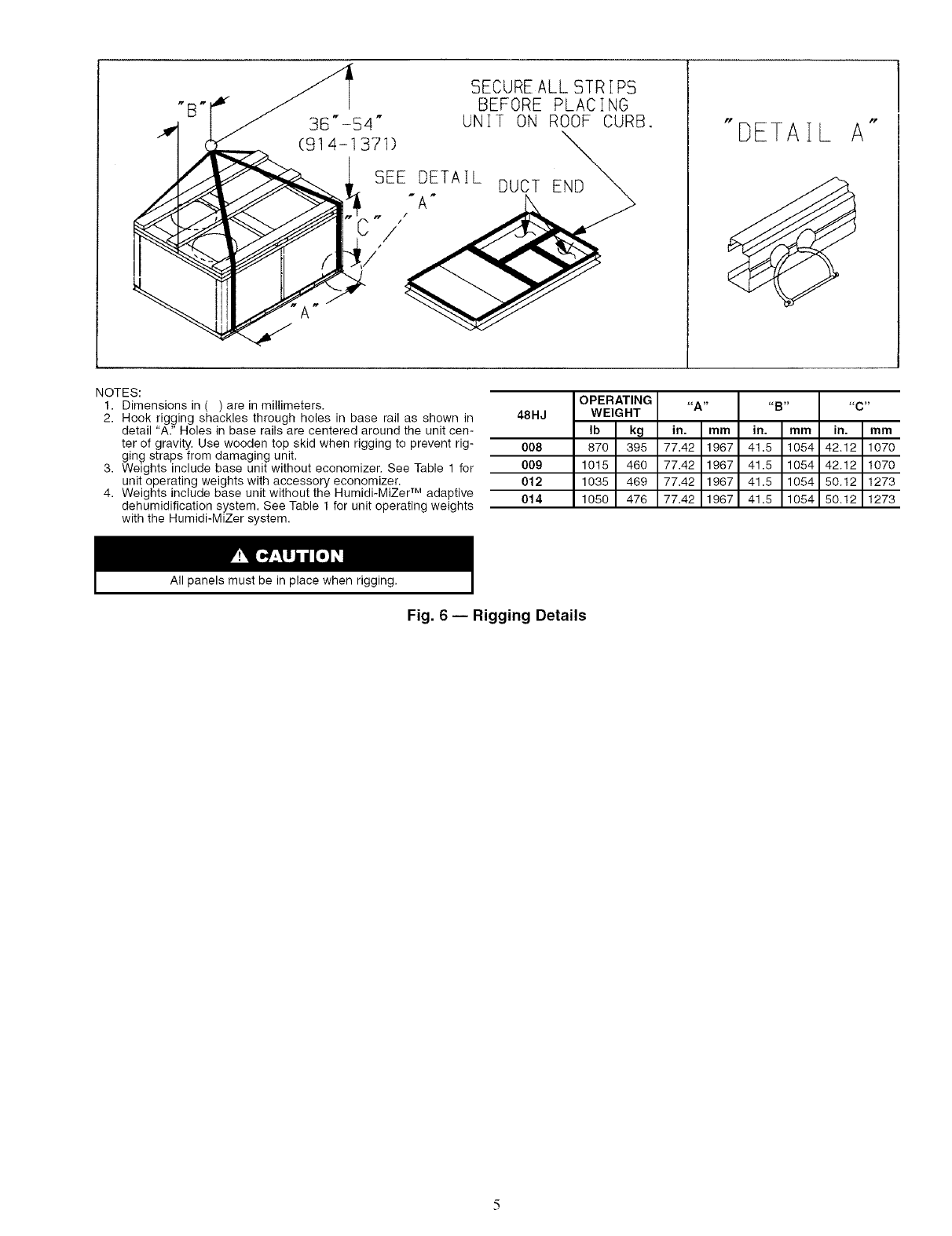
Step 4 -- Rig and Place Unit -- Inspect unit for
transportation &unage. File any clainl with transpoltation
agency. Keep unit uptight and do not drop. Spreader bars are
not required if top crating is left on unit. Rollel_ may be used to
move unit across a roof. Level by using unit frame as a refer-
ence. See Table 1 and Fig. 6 for additional information. Operat-
ing weight is shown in Table 1 and Fig. 6.
Lifting holes are provided in base rails as shown in Fig. 6
and 7. Refer to rigging instructions on unit.
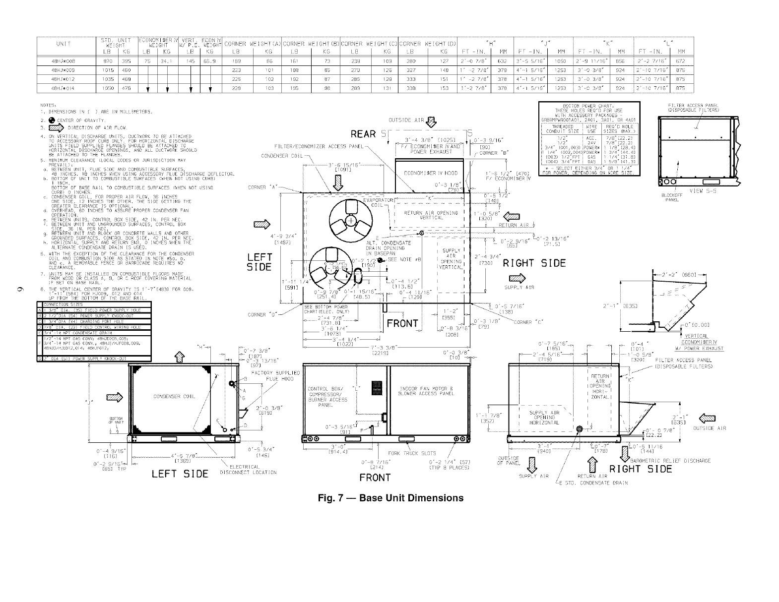
POSITIONING -- Maintain clearance around and above unit
to provide minimum distance fiom combustible materi_ds,
proper airflow, and service access. See Fig. 7.
Do not instull unit in an indoor location. Do not locate unit
air inlets near exhaust vents or other sources of contaminated
all:
Be sure that unit is installed so that snow will not block the
combustion intake or flue outlet.
Unit may be installed directly on wood flooring or on
Class A, B, or C roof-covering material when roof curb is used.
Although unit is weatherproof, guard against water fiom
higher level runoff and overhangs.
Position unit on roof curb so that the following clearances
are maintained: l/4-in, clearance between the roof curb and the
base rail inside the front and real: 0.0 in. clearance between the
roof curb and the base rail inside on the duct end of the unit.
This will result in the distance between the roof curb and the
base rail inside on the condenser end of the unit being approxi-
mately equal to Fig. 2, section C-C.
Ix_cate mechanical draft system flue assembly at least 48 in.
from an adjacent building o1 combustible material. Units hav-
ing accessory flue dischmge deflector lequire only 18 in. clear-
ance. When unit is located adjacent to public walkways, flue
assembly must be at least 7 ft above grade.
Flue gas can deteriorate building materi_ds. Orient unit so
that flue gas will not affect building materials.
Adequate combustion and ventilation air space must be pro-
vided for proper operation of this equipment. Be sure that in-
stallation complies with all local codes and Section 5.3, Air for
Combustion and Ventilation per NFGC (Natiomd Fuel Gas
Code), ANSI (American National Standards Institute) Z223.1 -
latest year and addendum Z223.1A-latest yem: In Canada, in-
stallation must be in accordance with the CANI.BI49.1 and
CAN 1.B 149.2 installation codes for gas burning appliances.
Flue vent dischmge must have a minimum horizontal clear-
ance of 4 ft from electric and gas meters, gas regulators, and
gas relief equipment.
After unit is in position, remove shipping materials and rig-
ging skids.
Step 5 -- Install Flue Hood -- Flue hood is shipped
screwed to the burner compartment access panel. Remove
fiom shipping location and, using screws provided, inst_dl flue
hood and screen in location shown in Fig. 7 and 8.
Step 6 -- Install Gas Piping -- Unit is equipped for
use with type of gas shown on nameplate. Refer to local
building codes, or in the absence of local codes, to
ANSI Z223.l-latest year and addendum Z223. l A-latest year
entitled NFGC. In Cana&t, installation must be in accordance
with the CANI .B149.1 and CANI .B149.2 installation codes
for gas burning appliances.
For natund gas applications, gas pressure at unit gas
connection must not be less than 4.0 in. wg or greater than
13.0 in. wg while unit is operating. For liquid propane and high
heat applications, the gas pressure must not be less than
5.0 in. wg or greater than 13.0 in. wg at the unit connection.
Size gas supply piping for 0.5-in. wg maximum pressure
drop. Do not use supply pipe sm_fller than unit gas connection.
Support gas piping as shown in the table in Fig. 9. For ex-
ample, a 3/4-in. gas pipe must have one field-fabricated support
beam every 8 ft. Therefore, an 18-ft long gas pipe would have a
minimum of 3 support beams. See Fig. 9 for typic_d pipe guide
and locations of external manual gas shutoff valve.
When connecting the gas line to the unit gas valve, the
installer MUST use a backup wrench to prevent valve
&_mage.
/
.<.
SECUREALL STRIPS
BEFORE PLACING
36"-54" UNIT ON ROOF CURB.
(91 4-1 371)
I SEE DETAIL
"DETAIL A"
NOTES:
1, Dimensions in ( ) are in millimeters.
2. Hook rigging shackles through holes in base rail as shown in 48HJ
detail "A." Holes in base rails are centered around the unit cen-
ter of gravity, Use wooden top skid when rigging to prevent rig- 008
ging straps from damaging unit,
3. Weights include base unit without economizer, See Table 1 for 00g
unit operating weights with accessory economizer. 012
4. Weights include base unit without the Humidi-MiZer TM adaptive 014
dehumidification system. See Table 1 for unit operating weights
with the Humidi-MiZer system.
OPERATING
WEIGHT
Ib kg
870 395
1015 460
1035 469
1050 476
"A"
in. mm
77.42 1967
77.42 1967
77.42 1967
77.42 1967
"a"
in. mm
41.5 1054
41.5 1054
41.5 1054
41.5 1054
"C"
in. mm
42.12 1070
42.12 1070
50.12 1273
50.12 1273
All panels must be in place when rigging.
Fig. 6 -- Rigging Details
STD UNIT
(;NI WEGH
4/ iJ÷O08 8r'O :oi 4
48_,_;_0i 2 1035 469
'/ RI CON
P,E< _EiGItT CORNER WEIGH (A)CORNEi _E OH (B C,')INER ,_E (H (C} ORNE dE([ (D "14 _ "J" "K _ "1 _
MM i=T¸ IN. MM FT IN.
_45 GS,g iB9 {76 /6_ ?:7 239 log 280 127¸ 2' 0 7/8" 632 3' S S/]{_= 1050 i2 >g /i/16 _ 856 i 2"v2 ?/IB" 6?2
22_ _02 /g2 87 _8_ /2_ 333 IS_ /' 2 _J8 _ 3_8 4 _ I S/18 _ _2_ i _' 0 3/8 _ g24 i 2" iO "_/1E__ _7_
2_ iO_l 1!_ 88 289 1_i 3_8 i_ _-2 "i_J_" _78 4"-i _/i_ _ i2_i i 3"-,0 _/_i _ 9J4 i2" _0 7/1_ _ 87_
NOTES
i. [} dN ON ]\ } AR ] Mi [M / RJ
2 0 CENTER OF¸ GR4ViTY
3 _ DIRECTION OF AIR FLOW
4 ON VER[]CAL OiSCHARGE dN/;S, {}.<CfWORK _0 B_ AYIAC_ED
_0 ACCESSORY ROOF CbRB ONLY¸ FOR _ORiZON]AL B:SCHARGE
8N:i5 FIELD SU!>PL]ED FLANGES SOOdLO BE AiiACHED i0
HOR[ZONiAL D:SCH_G_ OPENINGS, AND ALL DUCiWORK 5HObLD
BE A! :ACMED I0 :HE FLANOES.
5 HfN[MUM CLEARANCE (LOCAL COOE[_ OR JtJRiS[?f¢: ;ON HAY
o B_FWEEN UNfT, FLtJE 5:0E _NO COMBUSTIBLE StJRF/_C[:5,
_8 INCHES !8 iN(}I:E_ W_:N USfNG ACCESSORY FLtJE Of SClI_i_GE DEFLECTOR
b BOTTOM OF: uN[r ro COMBUSTIBLE SdRFAC_:5 (WHEI'_ NO: t'S!NC; CtJRt_)
/ :NCiL
BOTTOM OF¸ BASE RA[t TO COMBbS: ISLE 5tJRF/_CES (WHEN NO: tiSiN6
CURB) 0 ]NCHES
c CONDENSER CO:{, FOR PROPER AIR FLOW, 36 :NC}i_S
ONE SfDE, 12 INCHES T_tE OTilER THE SIDE GETTING THE
GRE#TER CLE_RANC_ 19 OPTIONAL¸
d OVERHEAD, 80 INCHES TO ASSdRE PROPER CONDeNSeR FAN
OPERAT] ON
e B:TNEEN UNfTS, CONTROt _OX SIDE_ 42 ]N PER NEC
? BETNEEN UNIT AND UNGROONOEOSURFACOS, OONTqO: BOX
SIDE, 36 iN, PER NEC,
g 3.:TNEEN UNIT _ND Bi OCK OR CONCRETE WALl S AND OTHER
GROUND:D SURFACES, CONTROl BOX SiC.E, 47_ iN PER N:C
h iiORIZONTAL 5bPPl Y AND RETt;R_ END, 0 ]NCqES dOEN THE
AI TERNATE CONDENSATE DRAIN IS dSE8
6 WIYM :_E EXCEPflON OF Y_E CLEARANCE FOR ;ME CONDENSER
COiL ANO OOMBUSiIOh ST:]E A2 SLATED IN NO:E #_, b,
,_f'@ c, A i_EMOVABb+FENCE OR BARRICADE REOUIRES NO
¢i :AR,tNCE
7 UN: T5 MAY _E :NSrA[[ El} ON CO_I_US: :f_: E FLOOR5 MADE
FROM WOODOR Ci AS5 A, 8, OR ¢ ROOF COt'ER:NG MATERIAl
IF SEI ON BA_E R_IL
8 :i_E k'_RT[CAL CENrER or: GRA_iT _' :5 / ¸ 7"[¸4837 FOR OO8,
_" 11_1S84] FOR HJO09, 012 AND 0i4
UP FROM T:I[_ BOITOM Or' ]_f! BASE RA:I
@
80T:O_
SF UNIT
CON )l NSER COil
LEFT S!DE
LEFT
SIDE
O' 3 1Z/It
{973
tC [07Y UPP[ lEO
_{ FlUE OOD
_3' 4 //4=_J
[1022]
?
o" 3/4 _
\' _LECTRiCAL
D]SCONN!_CT [ OCA: :0_
' 3 /["
[221 c{]
[208]
F/ [!CONObI/!S[i IV
SUPPLY AR
O" 0 3'8"
[10]
< _ os
"<-. [138]
0"3 i/8 ..... (}0RE C
[;9]
m
CON I RO fOX/ "t _
CO >ROSSOR/
BU NE/ ACCESS
PANS
rim 1::::;=3
3•0" --
[9!44 OK TRUCK ilOF
O" 8 /!g"
2i4
FRONT
Iil_
/
//
'2 / " I
(I P ;! P A_ )
[L_Cr [[T{fR 3/4" OR 1 is4"
FOR POWER, DEPEND[qG 04 WiRE S]Z
[iOS] i i fiO]}
fIL 7ER ACC{S }#NIt
':D;SPOS_S: E F]LTE_S)
/
V{Td {
pANEL
UPPLY AiR /RTTURN AIR
£E STO, COND NSAT£ ©RA[N
..... 2" 2" [5t0] .....
1{7[]
} ) S!P&
ECONO vSER q
_,/ PON[ EXIJA JSI
ILTFiR 4CCESS PANEL
Fig. 7iBase Unit Dimensions
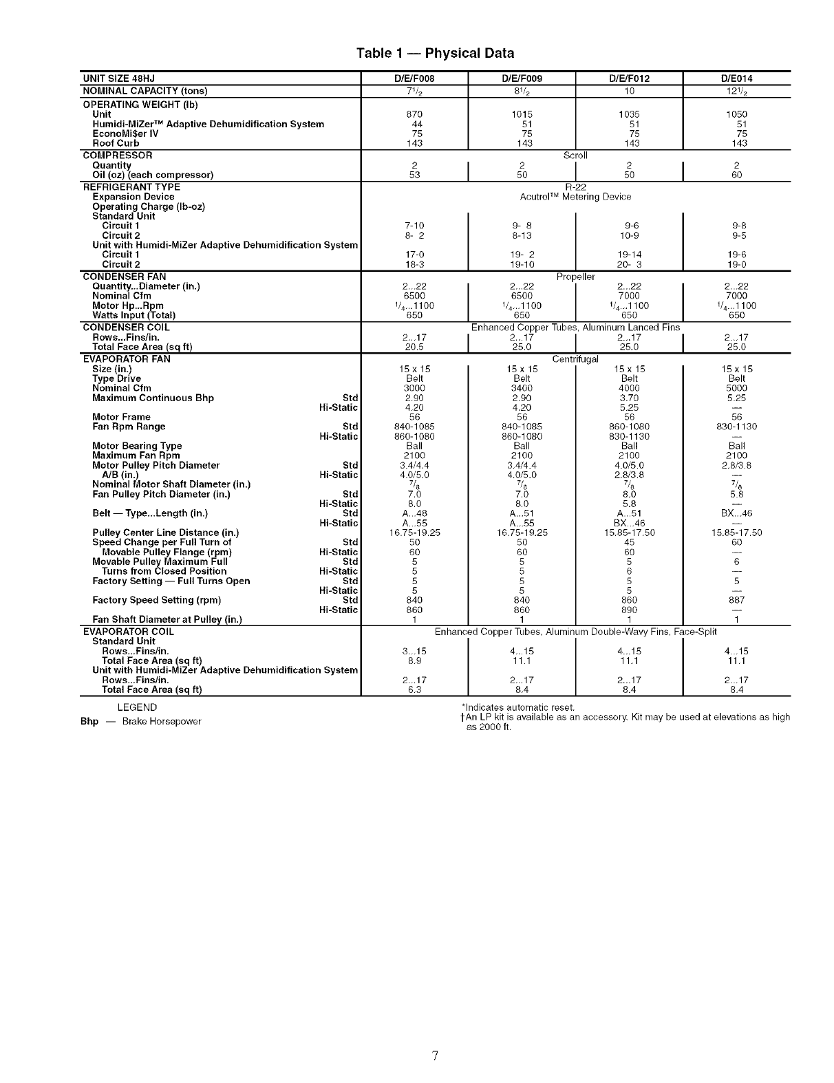
Table1 -- Physical Data
UNIT SIZE 48HJ D/E/F008 D/E/F009 D/E/F012 D/E014
NOMINAL CAPACITY (tons) 71/2 81/2 10 121/2
OPERATING WEIGHT (Ib)
Unit 870 1015 1035 1050
Humidi-MiZer TM Adaptive Dehumidification System 44 51 51 51
EconoMi$er IV 75 75 75 75
Roof Curb 143 143 143 143
COMPRESSOR Scroll
ouantity 2 I 2 I 2 I 2
Oil (oz) (each compressor) 53 50 50 60
REFRIGERANT TYPE R-22
Expansion Device Acutrel TM Metering Device
Operating Charge (Ib-oz)
Standard Unit
Circuit I 7-10 9- 8 9-6 9-8
Circuit 2 8- 2 8-13 10-9 9-5
Unit with Humidi-MiZer Adaptive Dehumidification System 17-0 19- 2 19-14 19-6
18-3 19-10 20- 3 19-0
Propeller
2-.22 2-.22 2.-22 I 2.-22
6500 6500 7000 ] 7000
114,.,1100 114,.,1100 114.,,1100 114.,,1100
650 650 650 650
Enhanced Copper Tubes, Aluminum Lanced Fins
2,.,17 I 2.,.17 I 2.,.17 I 2..,17
20.5 25.0 25.0 25,0
Centrifugal
Circuit 1
Circuit 2
CONDENSER FAN
Quantity...Diameter (in,)
Nominal Cfm
Motor Hp.,.Rpm
Watts Input (Total)
CONDENSER COIL
Rows.,,Fins/in.
Total Face Area (sq ft)
EVAPORATOR FAN
Size (in,)
Type Drive
Nominal Cfm
Maximum Continuous Bhp
Motor Frame
Fan Rpm Range
Std
Hi-Static
Std
Hi-Static
Motor Bearing Type
Maximum Fan Rpm
Motor Pulley Pitch Diameter Std
A/B (in.) Hi-Static
Nominal Motor Shaft Diameter (in.)
Fan Pulley Pitch Diameter (in.)
Belt -- Type,,.Length (in,)
Pulley Center Line Distance (in.)
Speed Change per Full Turn of
Movable Pulley Flange (rpm)
Movable Pulley Maximum Full
Turns from Closed Position
Factory Setting -- Full Turns Open
Factory Speed Setting (rpm)
Fan Shaft Diameter at Pulley (in.)
EVAPORATOR COIL
Standard Unit
Rows...Fins/in,
Total Face Area (sq ft)
Std
Hi-Static
Std
Hi-Static
Std
Hi-Static
Std
Hi-Static
Std
Hi-Static
Std
Hi-Static
Unit with Humidi-MiZer Adaptive Dehumidification System
Rows...Fins/in,
Total Face Area (sq ft)
LEGEND
Bhp -- Brake Horsepower
15x15
Belt
3000
2,90
4,20
56
840-1085
860-1080
Ball
2100
3.4/4,4
4.0/5,0
7/8
7.0
8.0
A.-48
A.-55
16.75-19.25
50
60
5
5
5
5
840
860
1
3,,,15
8,9
2...17
6.3
15x15
Belt
3400
2,90
4,20
56
840-1085
860-1080
Ball
2100
3,4/4.4
4,0/5.0
7.0
8.0
A...51
A.-55
16.75-19,25
50
60
5
5
5
5
840
860
1
15x15
Belt
4000
3,70
5,25
56
860-1080
830-1130
Ball
2100
4.0/5.0
2,8/3.8
7&
8,0
5,8
A...51
BX..,46
15,85-17,50
45
60
5
6
5
5
860
890
1
15x15
Belt
5000
5.25
56
830-1130
Ball
2100
2.8/3.8
7&
5.8
BX.-46
15.85-17.50
6O
6
5
887
1
Enhanced Copper Tubes, Aluminum Double-Wavy Fins, Face-Split
4_.15 4._15
11.1 11.1
2,_17 2...17
8.4 8.4
*Indicates automatic reset,
4_,15
11.1
2-,17
8.4
tAn LP kit is available as an accessory. Kit may be used at elevations as high
as 2000 ft.
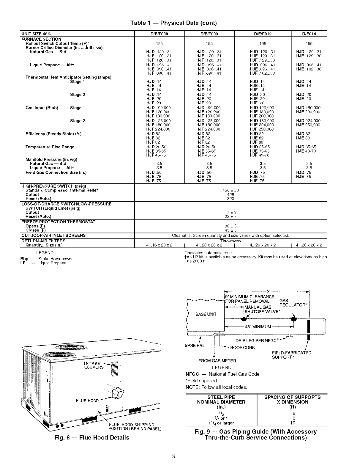
Table 1 -- Physical Data (cont)
UNIT SIZE 48HJ
FURNACE SECTION
Rollout Switch Cutout Temp (F)*
Burner Orifice Diameter (in, .,.drill size)
Natural Gas -- Std
Liquid Propane -- Altt
Thermostat Heat Anticipator Setting (amps)
Stage 1
Stage 2
Gas Input (Btuh) Stage 1
Stage 2
Efficiency (Steady State) (%)
Temperature Rise Range
Manifold Pressure (in, wg)
Natural Gas -- Std
Liquid Propane -- Altt
Field Gas Connection Size (in,)
HIGH-PRESSURE SWITCH (psig)
Standard Compressor Internal Relief
Cutout
Reset (Auto,)
LOSS-OF-CHARGE SWITCH/LOW-PRESSURE
SWITCH (Liquid Line) (psig)
Cutout
Reset (Auto,)
FREEZE PROTECTION THERMOSTAT
Opens (F)
Closes (F)
OUTDOOR-AIR INLET SCREENS
RETURN-AIR FILTERS
Ouantity..,Size (in.)
LEGEND
Bhp -- Brake Horsepower
LP -- Liquid Propane
D/E/F008 D/E/F009 D/E/F012 D/E014
195
HJD.120-.31
HJE.120-.31
HJF.120-.31
HJD.096-.41
HJE.096...41
HJF.096-.41
HJD.14
HJE.14
HJF.14
HJD.14
HJE.20
HJF.20
HJD 90,000
HJE 120,000
HJF160,000
HJD 125,000
HJE 180.000
HJF 224,000
HJD 82
HJE 62
HJF 82
HJD 20-50
HJE 35-65
HJF 45-75
3.5
3.5
HJD .50
HJE .75
HJF .75
195
HJD .120...31
HJE.120-.31
HJF.120.-31
HJD.096...41
HJE.096-.41
HJF.096.-41
HJD.14
HJE.14
HJF.14
HJD.14
HJE.20
HJF.20
HJD 90,000
HJE 120,000
HJF 160,000
HJD 125,000
HJE 180,000
HJF 224,000
HJD 82
HJE 82
HJF 82
HJD 20-50
HJE 35-65
HJF 45-75
3.5
3.5
HJD .50
HJE .75
HJF .75
195
HJD .120-.31
HJE.120...31
HJF.129-.30
HJD .096-.41
HJE.096.-41
HJF.102-.38
HJD.14
HJE.14
HJF.14
HJD.20
HJE.20
HJF.20
HJD 120,000
HJE 180,000
HJF 200.000
HJD 160,000
HJE 224,000
HJF 250,000
HJD 82
HJE 62
HJF 80
HJD 35-65
HJE 35-65
HJF 40-70
3.5
3.5
HJD .75
HJE .75
HJF .75
195
HJD.120...31
HJE.129-.30
HJD .096-.41
HJE.102.-38
HJD.14
HJE.14
HJD.20
HJE.20
HJD 180,000
HJE 200.000
HJD 224,000
HJE 250.000
HJD 82
HJE 60
HJD 35-65
HJE 40-70
3.5
3.5
HJD .75
HJE .75
450 _+50
428
32O
7_+3
22_+7
30_+5
45_+5
Cleanable. Screen quantity and size varies with option selected.
Throwaway
4_.16 x20 x2 I 4._20 x 20 x 2 I 4._20 x 20 x 2 I 4...20 x 20 x 2
*Indicates automatic reset.
tAn LP kit is available as an accessory. Kit may be used at elevations as high
as 2000 ft.
FLUE HOOD SHIPPING
POSITION (BEHIND PANEL)
Fig. 8-- Flue Hood Details
., x "l
9" MINIMUM CLEARANCE I
FOR PANEL REMOVAL GAS I
REGULATOR _
*-- -- MANUALGAS I
,SHUTOFF VALVE* I
IP LEG PER NFGC * _'r£b J_
BASE RAIL Ii L-._._ ROOF CURB /
FIELD-FABRICATED
SUPPORT*
FROM GAS METER
LEGEND
NFGC -- National Fuel Gas Code
•Field supplied.
NOTE: Follow all local codes.
STEEL PIPE SPACING OF SUPPORTS
NOMINAL DIAMETER X DIMENSION
(in.) (ft)
1/2 6
3/4 or 1 8
11/4 or larger 10
Fig. 9 -- Gas Piping Guide (With Accessory
Thru-the-Ourb Service Connections)
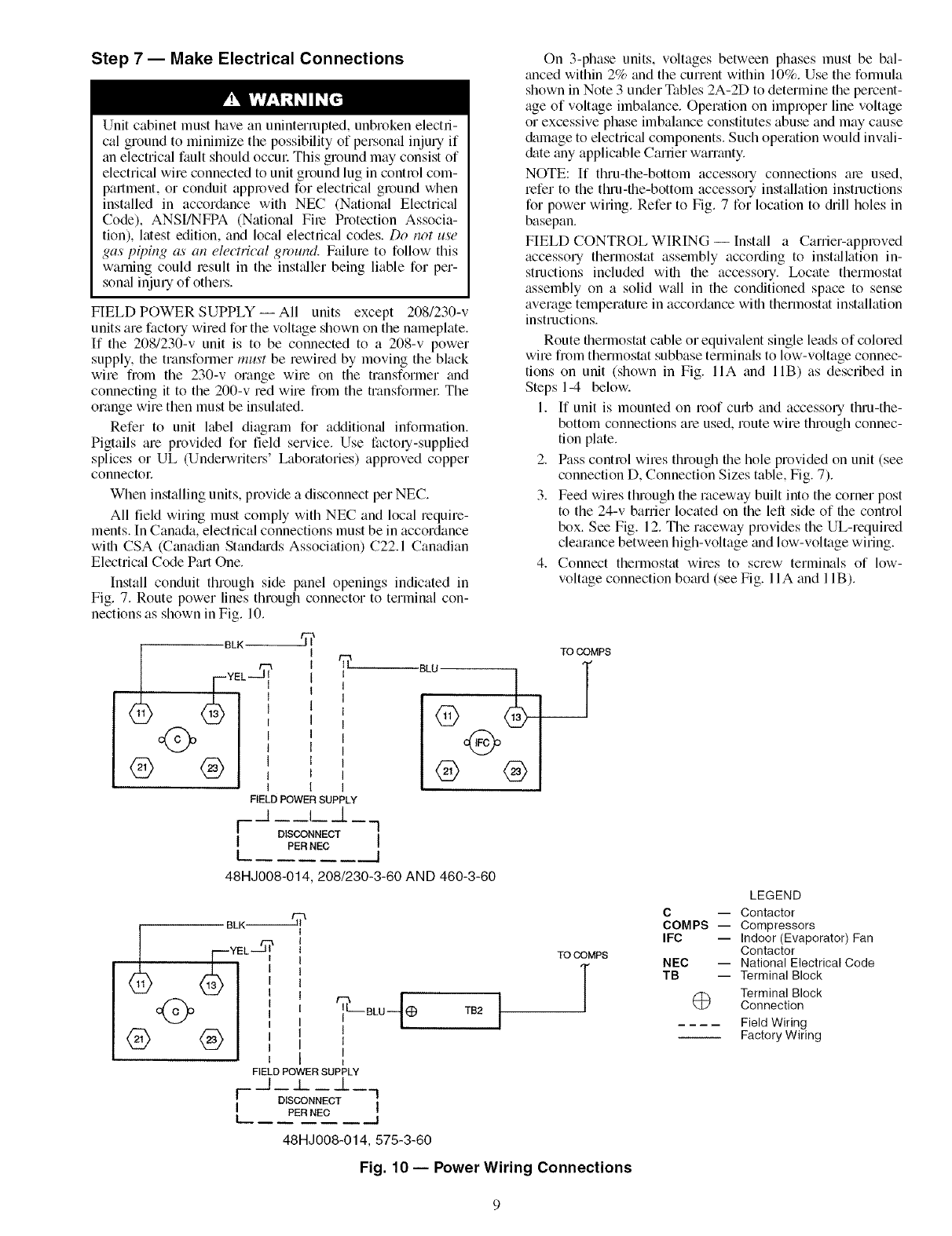
Step 7 -- Make Electrical Connections
Unit cabinet must have an uninterrupted, unbroken electri-
cal ground to minimize the possibility of personal inju Uif
an electrical fault should occm: This ground may consist of
electrical wire connected to unit ground lug in control com-
partment, or conduit appl_)ved for electrical ground when
installed in accordance with NEC (National Electrical
Code), ANSI/NFPA (National File Protection Associa-
tion), latest edition, and local electrical codes. Do not use
gas piping as an electrical ground. Failure to follow this
warning could result in the inst_dler being liable for per-
somd inju Uof others.
FIELD POWER SUPPLY -- All units except 208/230-v
units are factory wired for the voltage shown on the nameplate.
If the 208/230-v unit is to be connected to a 208-v power
supply, the transformer must be rewired by moving the black
wire fiom the 230-v orange wile on the transformer and
connecting it to the 200-v red wire fiom the transformer The
orange wire then must be insulated.
Refer to unit label diagram for additional infommtion.
Pigtails are provided for field service. Use factou-supplied
splices or UL (Undelwriters' Laboratories) approved copper
connectoL
When installing units, provide a disconnect per NEC.
All field wiring must comply with NEC and local require-
ments. In Canada, electrical connections must be in accordance
with CSA (Canadian Standads Associaion) C22.1 Canadian
Electrical Code Part One.
Install conduit through side panel openings indicaed in
Fig. 7. Route power lines through connector to terminal con-
nections as shown in Fig. 10.
BLK--_-_J_
5'
FIELD POWER SUPPLY
j __L_/
F-- D IS_NEC T ----1
I PERNEC I
I J
BLU
®
®
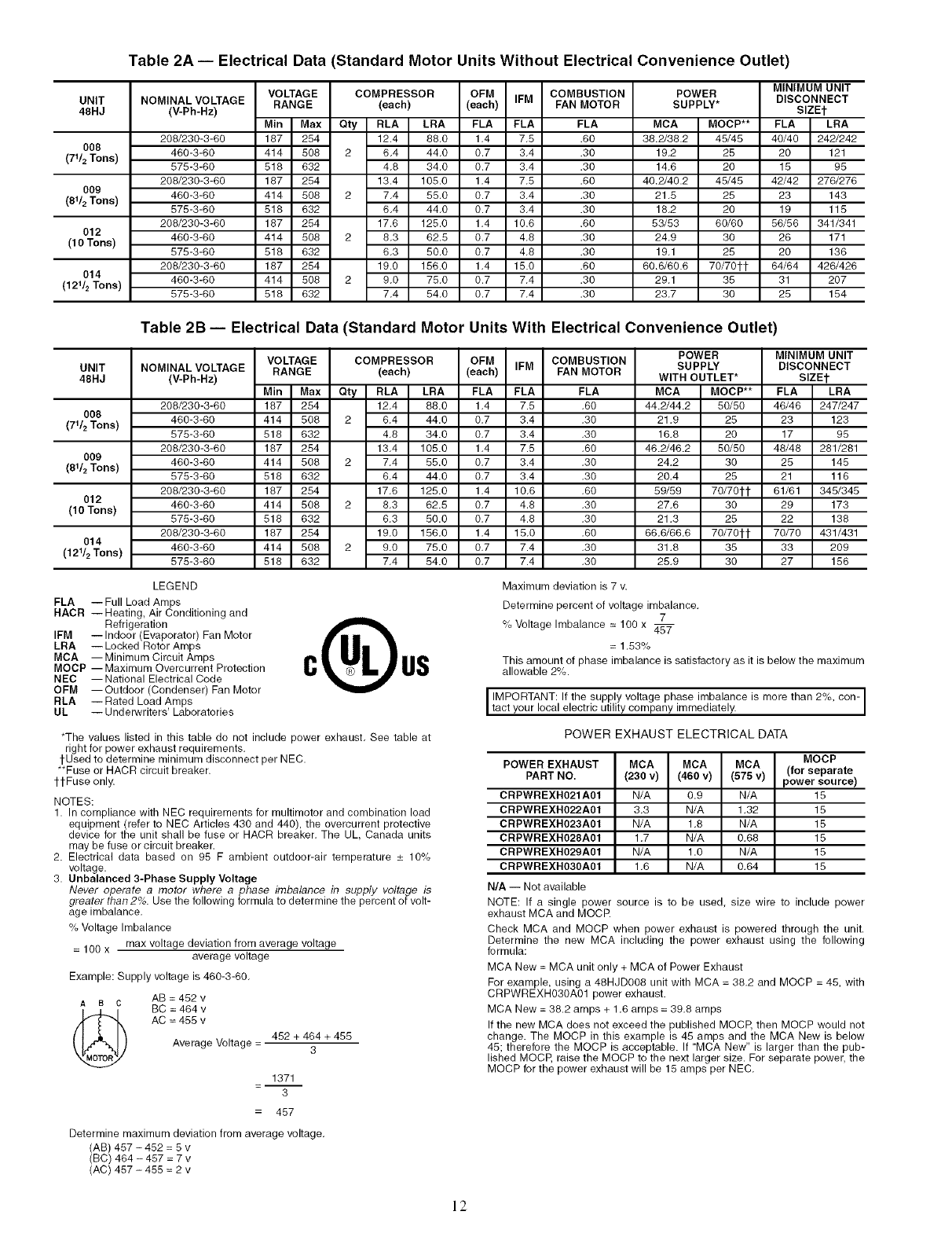
On 3-phase units, voltages between phases must be bal-
anced within 2% and the current within 10%. Use the fommla
shown in Note 3 under Tables 2A-2D to determine the percent-
age of voltage imbalance. Operation on improper line voltage
or excessive phase imbalance constitutes abuse and may cause
&image to electric_fl components. Such operation would inv_fli-
&tte any applicable Carrier warranty.
NOTE: If thru-the-bottom accesso Uconnections are used,
refer to the thin-the-bottom accessol T installation instructions
for power wiring. Refer to Fig. 7 for location to &ill holes in
basepan.
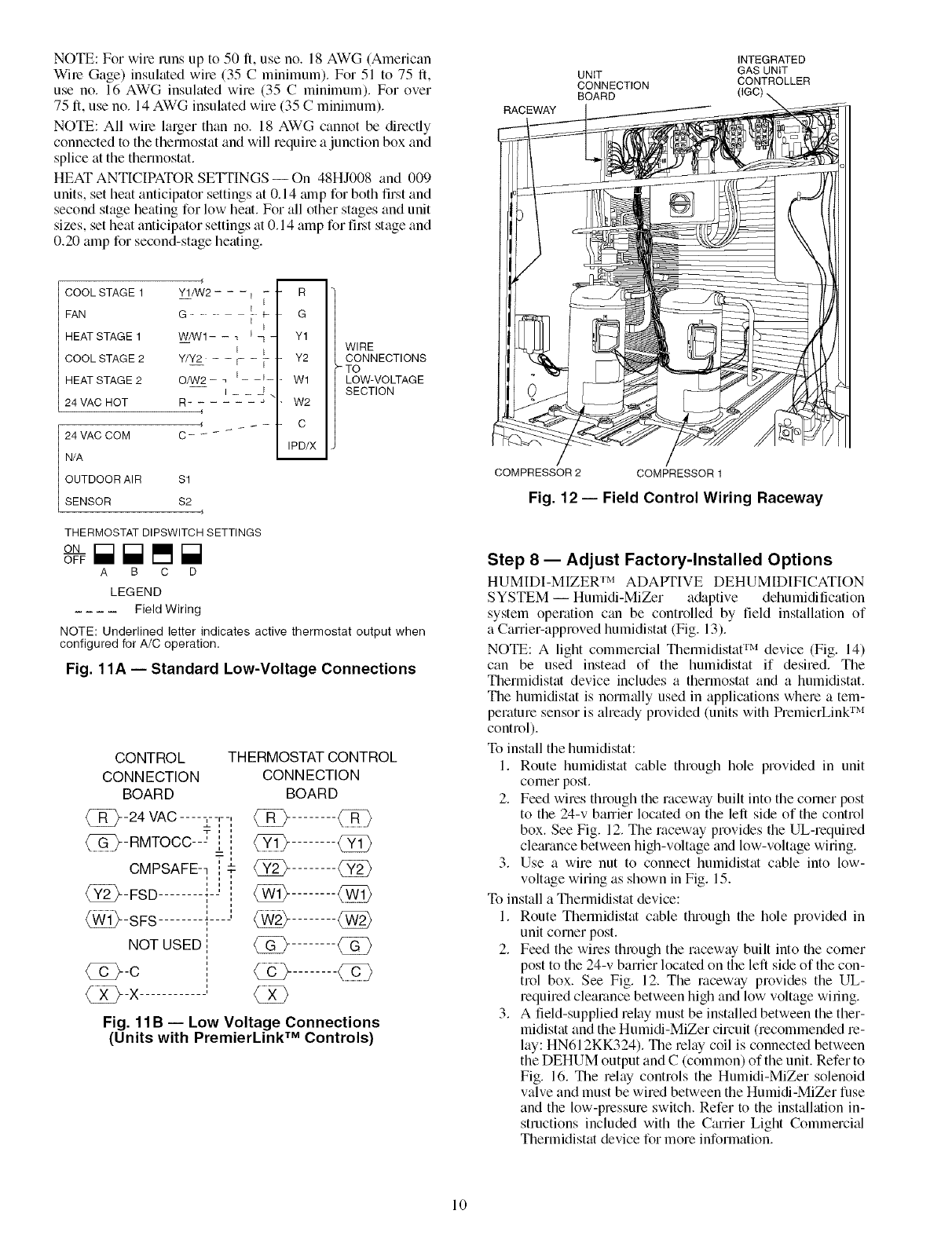
FIELD CONTROL WIRING -- Install a Carrier-approved
accesso Uthermostat assembly according to inst_dlation in-
structions included with the accesso U. Ix)cate thermostat
assembly on a solid wall in the conditioned space to sense
average temperature in accordance with thermostat installation
instructions.
Route thermostat cable or equivalent single leads of colored
wire from thermostat subbase terminals to low-voltage connec-
tions on unit (shown in Fig. IIA and lIB) as described in
Steps 1-4 below.
1. ff unit is mounted on roof curb and accesso Uthru-the-
bottom connections are used, route wire through connec-
tion plate.
2. Pass control wires through the hole provided on unit (see
connection D, Connection Sizes table, Fig. 7).
3. Feed wires through the raceway built into the corner post
to the 24-v barrier located on the left side of the control
box. See Fig. 12. The raceway provides the UL-required
clearance between high-voltage and low-voltage wiring.
4. Connect thermostat wires to screw terminals of low-
voltage connection boad (see Fig. 11A and 11B).
TO COMPS
48HJ008-014, 208/230-3-60 AND 460-3-60
®
BLK-_iii_
FIELD POWER SUPPLY
_L /
F -- --_L_.7
DISCONNECT
IPER NEC I
L__J
48HJ008-014, 575-3-60
BLU_
I
I
TB2 I
TO COMPS
LEGEND
C -- Contactor
COMPS -- Compressors
IFC -- Indoor (Evaporator) Fan
Contactor
NEC -- National Electrical Code
TB -- Terminal Block
@ Terminal Block
Connection
Field Wiring
Factory Wiring
Fig. 10- Power Wiring Connections
NOTE: For wire runs up to 50 ft, use no. 18 AWG (American
Wile Gage) insulated wire (35 Cminimum). For 51 to 75 fl,
use no. 16 AWG insulated wire (35 Cminimum). For over
75 fl, use no. 14 AWG insulated wire (35 Cminimum).
NOTE: All wile larger than no. 18 AWG cannot be directly
connected to the thermostat and will require a junction box and
splice at the thermostat.
HEAT ANTICIPATOR SETTINGS -- On 48HJ008 and 009
units, set heat anticipator settings at 0.14 mnp for both first and
second stage heating for low heat. For all other stages and unit
sizes, set heat anticipator settings at 0.14 amp for fil.st stage and
0.20 amp for second-stage heating.
RACEWAY
UNIT
CONNECTION
BOARD
INTEGRATED
GAS UNIT
CONTROLLER
COOL STAGE 1
FAN
HEAT STAGE 1
COOL STAGE 2
HEAT STAGE 2
24 VAC HOT
24 VAC COM
N/A
OUTDOOR AIR S1
SENSOR S2
m
Y1/W2- - - i - - R
-- [
[
G...........................F G
W/W1- - _ q - Y1
Y/Y2 - - r- - V- Y2
k
O/W2- _ E ___ _ W1
R- " W2
C- _
IPD/X
WIRE
CONNECTIONS
-TO
LOW-VOLTAGE
SECTION
THERMOSTAT DIPSWITCH SETTINGS
ON
A B C D
LEGEND
Field Wiring
NOTE: Underlined letter indicates active thermostat output when
configured for A/C operation.
Fig. 11A- Standard Low-Voltage Connections
CONTROL
CONN ECTION
BOARD
@-24 VAC .... -,--,--,
__,,
@-RMTOCC---' ',,
i"
CMPSAFE-- , r
@-FSD .......... "
@-SFS
NOT USED
@-C
@-X-
THERMOSTAT CONTROL
CONN ECTION
BOARD
Fig. 11B-- Low Voltage Connections
(Units with PremierLink TM Controls)
COMPRESSOR 2 COMPRESSOR 1
Fig. 12- Field Control Wiring Raceway
Step 8 -- Adjust Factory-Installed Options
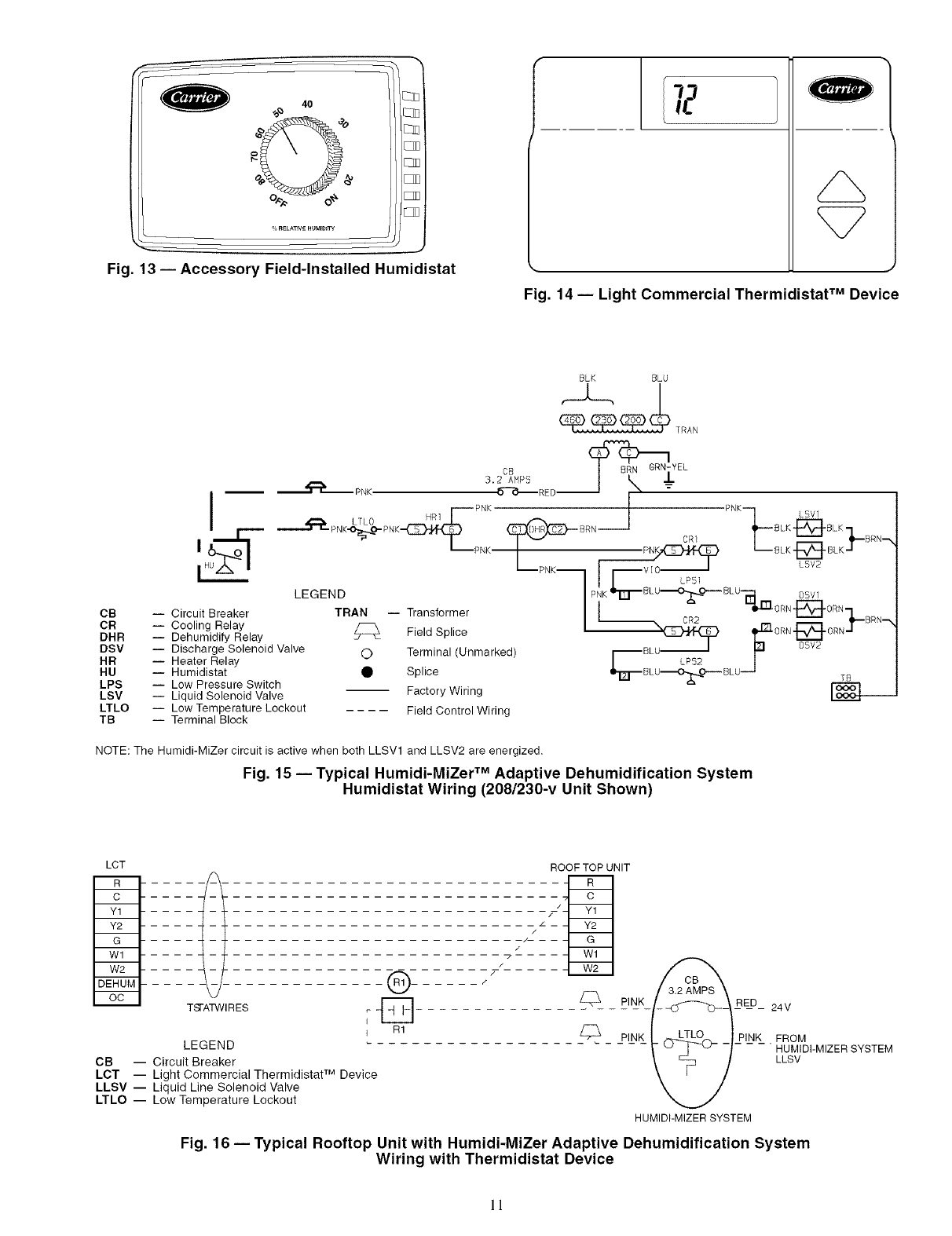
HUMIDI-MIZER TM ADAPTIVE DEHUMIDIFICATION
SYSTEM -- Humidi-MiZer a&_ptive dehumidification
system operation can be controlled by field installation of
aCarrier-approved humidistat (Fig. 13).
NOTE: A light commercial Thermidistat TM device (Fig. 14)
can be used instead of the humidistat if desired. The
Thermidistat device includes a thermostat and a humidistat.
The humidistat is norm_dly used in applications where a tem-
perature sensor is aheady provided (units with PremierLink TM
control).
To install the humidistat:
1. Route humidistat cable through hole provided in unit
corner post.
2. Feed wires through the raceway built into the corner post
to the 24-v barrier located on the left side of the control
box. See Fig. 12. The laceway provides the UL-required
cle_uance between high-voltage and low-voltage wiring.
3. Use a wire nut to connect humidistat cable into low-
voltage wiring as shown in Fig. 15.
To install a Thermidistat device:
1. Route Thermidistat cable through the hole provided in
unit corner post.
2. Feed the wires through the raceway built into file corner
post to the 24-v barrier located on the left side of the con-
trol box. See Fig. 12. The raceway provides the UL-
required clearance between high and low voltage wiling.
3. A field-supplied relay must be installed between the ther-
midistat and the Humidi-MiZer circuit (recommended re-
lay: HN612KK324). The relay coil is connected between
the DEHUM output and C (common) of the unit. Refer to
Fig. 16. The relay controls the Humidi-MiZer solenoid
valve and must be wired between the Humidi-MiZer fuse
and the low-pressure switch. Refer to the installation in-
structions included with the Carrier LigN Commercial
Thermidistat device for more information.
10
4O
c_
C_
Elm
lED
[ZD
Fig. 13- Accessory Field-Installed Humidistat
Fig. 14 -- Light Commercial Thermidistat TM Device
CB
CR
DHR
DSV
HR
HU
LPS
LSV
LTLO
TB
BLK BLU
OB _BRN GRN-YEL
3.2 AHPS t _ _J-,
.b-_-_-- RED,__
I HR1 PNK ._ PNK LSV1
BLK_BLK-ILTLO CR1 BRN--_
i_uA, I L_N<m I r--vlcS Lsv2
LPS1
LEGEND / P!!K_J--BLU_ 0- BLU-'_I DSVI
-- Circl)it Breaker TRAN -- Transformer | I _I_'ORN'E_ORN-I RN
C°_iRfyl_Ylay _: Field Splice | _'--N,_)_ I_Zl0RN.{_. 0RN.._ B -N
Discharge Solenoid Valve d'> Terminal Unmarked _BLU._I I_ OSV2
Heater Relay _ / 'PS2 I
• Splice
Humidistat °'_-- BLU--O_ 0"-" BLU'-'_ TB
-- Low Pressure Switch
-- Liquid Solenoid Valve Factory Wiring 166<34.--
-- Low Temperature Lockout Field Control Wiring
-- Terminal Block
NOTE: The Humidi-MiZer circuit is active when both LLSV1 and LLSV2 are energized.
Fig. 15- Typical Humidi-MiZer TM Adaptive Dehumidification System
Humidistat Wiring (208/230-v Unit Shown)
LCT
....--I..............®......
TSTATWIRES _ _]-
R1
LEGEND
CB -- Circuit Breaker
LCT -- Light Commercial Thermidistat TM Device
LLSV -- Liquid Line Solenoid Valve
LTLO -- Low Temperature Lockout
ROOF TOP UNIT
PINK _/___ _RE_D_ 24V
PINK __PI_NK_ .
HUMIDI-MI7ER SYSTEM
FROM
HUMIDI-MIZER SYSTEM
LLSV
Fig. 16- Typical Rooftop Unit with Humidi-MiZer Adaptive Dehumidification System
Wiring with Thermidistat Device
11
UNIT
48HJ
O08
(71_Tons)
009
(81/2Tons)
012
(10 Tons)
014
(121_Tons)
Table 2A -- Electrical Data (Standard Motor Units Without Electrical Convenience Outlet)
VOLTAGE COMPRESSOR OFM COMBUSTION
NOMINAL(v.Ph.Hz)VOLTAGE RANGE (each) (each) IFM FAN MOTOR
Min Max Qty RLA LRA FLA FLA FLA
208/230-3-60 187 254 12.4 88.0 1.4 7.5 .60
460-3-60 414 508 2 6.4 44.0 0.7 3.4 .30
575-3-60 518 632 4.8 34.0 0.7 3.4 .30
208/230-3-60 187 254 13.4 105.0 1.4 7.5 .60
460-3-60 414 508 2 7.4 55.0 0.7 3.4 .30
575-3-60 518 632 6.4 44.0 0.7 3.4 .30
208/230-3-60 187 254 17.6 125.0 1.4 10.6 .60
460-3-60 414 508 2 8.3 62.5 0.7 4.8 .30
575-3-60 518 632 6.3 50.0 0.7 4.8 .30
208/230-3-60 187 254 19.0 156.0 1.4 15.0 .60
460-3-60 414 508 2 9.0 75.0 0.7 7.4 .30
575-3-60 518 632 7.4 54.0 0.7 7.4 .30
MINIMUM UNIT
POWER DISCONNECT
SUPPLY* SIZEt
MCA MOCP** FLA LRA
38.2_8.2 45/45 40/40 242/242
19.2 25 20 121
14.6 20 15 95
40.2_0.2 45/45 42/42 276/276
21.5 25 23 143
18.2 20 19 115
5_53 60/60 56/56 341/341
24.9 30 26 171
19.1 25 20 136
60.6/60.6 70/70_t 64/64 426/426
29.1 35 31 207
23.7 30 25 154
Table 2B -- Electrical Data (Standard Motor Units With Electrical Convenience Outlet)
UNIT
48HJ
008
(71_Tons)
009
(81/2Tons)
012
(10 Tons)
014
(121/2 Tons)
VOLTAGE COMPRESSOR OFM COMBUSTION
NOMINAL VOLTAGE RANGE (each) (each) IFM FAN MOTOR
(V-Ph-Hz)
Min Max Qty RLA LRA FLA FLA FLA
208/230-3-60 187 254 12.4 88.0 1.4 7.5 .60
460-3-60 414 508 2 6.4 44.0 0.7 3.4 .30
575-3-60 518 632 4.8 34.0 0.7 3.4 .30
208/230-3-60 187 254 13.4 105.0 1.4 7.5 .60
460-3-60 414 508 2 7.4 55.0 0.7 3.4 .30
575-3-60 518 632 6.4 44.0 0.7 3.4 .30
208/230-3-60 187 254 17.6 125.0 1.4 10.6 .60
460-3-60 414 508 2 8.3 62.5 0.7 4.8 .30
575-3-60 518 632 6.3 50.0 0.7 4.8 .30
208/230-3-60 187 254 19.0 156.0 1.4 15.0 .60
460-3-60 414 508 2 9.0 75.0 0.7 7.4 .30
575-3-60 518 632 7.4 54.0 0.7 7.4 .30
POWER MINIMUM UNIT
SUPPLY DISCONNECT
WITH OUTLET* SIZEt
MCA MOCP** FLA LRA
44.2/44.2 50/50 46/46 247/247
21.9 25 23 123
16.8 20 17 95
46.2/46.2 50/50 48/48 281/281
24.2 30 25 145
20.4 25 21 116
59/59 70/701-_ 61/61 345/345
27.6 30 29 173
21.3 25 22 138
66.6/66.6 70/70tt 70/70 431/431
31.8 35 33 209
25.9 30 27 156
LEGEND
FLA -- Full Load Amps
HACR --Heating, Air Conditioning and
Refrigeration
IFM --Indoor (Evaporator) Fan Motor
LRA --Locked Rotor Amps
MCA --Minimum Circuit Amps
MOCP -- Maximum Overcurrent Protection
NEC --National Electrical Code
OFM --Outdoor (Condenser) Fan Motor
RLA --Rated Load Amps
UL -- Underwriters' Laboratories
*The values listed in this table do not include power exhaust. See table at
right for power exhaust requirements.
tUsed to determine minimum disconnect per NEC.
**Fuse or HACR circuit breaker.
ttFuse only.
NOTES:
1. In compliance with NEC requirements for multimotor and combination load
equipment (refer to NEC Articles 430 and 440), the overcurrent protective
device for the unit shall be fuse or HACR breaker. The UL, Canada units
may be fuse or circuit breaker.
2. Electrical data based on 95 F ambient outdoor-air temperature _+ 10%
voltage.
3. Unbalanced 3-Phase Supply Voltage
Never operate a motor where, a phase imbalance in supply voltage is
greater than 2%. Use the following formula to determine the percent of volt-
age imbalance.
% Voltage Imbalance
= 100 x max voltage deviation from average voltage
average voltage
Example: Supply voltage is 460-3-60.
AB = 452 v
ABC BC = 464 v
AC =455v
Average Voltage = 452 + 464 + 455
3
1371
3
457
Determine maximum deviation from average voltage.
(AB) 457 -452 = 5 v
(BC) 464 - 457 = 7 v
(AC) 457 - 455 = 2 v
Maximum deviation is 7 v.
Determine percent of voltage imbalance,
7
% Voltage Imbalance =100 x 45_
= 1,53%
This amount of phase imbalance is satisfactory as it is below the maximum
allowable 2%.
IMPORTANT: If the supply voltage phase imbalance is more than 2%, con-
tact your oca e ectr cut ty company turned ate y.
POWER EXHAUST ELECTRICAL DATA
POWER EXHAUST MCA MCA MCA MOCP
(for separate
PART NO. (230 v) (460 v) (575 v) power source)
CRPWREXH021A01 N/A 0.9 N/A 15
CRPWREXH022A01 3.3 N/A 1.32 15
CRPWREXH023A01 N/A 1.8 N/A 15
CRPWREXH028A01 1.7 N/A 0.68 15
CRPWREXH029A01 N/A 1.0 N/A 15
CRPWREXH030A01 1.6 N/A 0.84 15
N/A -- Not available
NOTE: If a single power source is to be used, size wire to include power
exhaust MCA and MOCR
Check MCA and MOCP when power exhaust is powered through the unit.
Determine the new MCA including the power exhaust using the following
formula:
MCA New = MCA unit only + MCA of Power Exhaust
For example, using a 48HJD008 unit with MCA = 38.2 and MOCP = 45, with
CRPWREXH030A01 power exhaust.
MCA New = 38.2 amps + 1.6 amps = 39.8 amps
If the new MCA does not exceed the published MOCE then MOCP would not
change. The M©CP in this example is 45 amps and the MCA New is below
45; therefore the MOCP is acceptable. If MCA New" is larger than the pub-
lished M©CP, raise the MOCP to the next larger size. For separate power, the
MOCP for the power exhaust will be 15 amps per NEC.
12
UNIT
48HJ
008
009
012
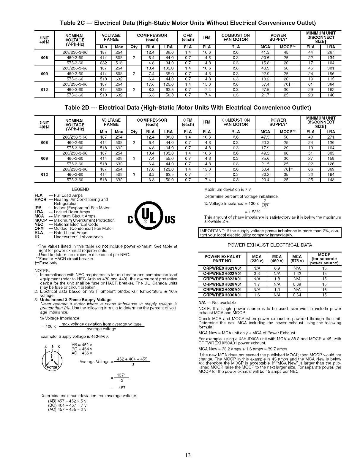
Table 2C -- Electrical Data (High-Static Motor Units Without Electrical Convenience Outlet)
NOMINAL VOLTAGE COMPRESSOR OFM IFM COMBUSTION
VOLTAGE RANGE (each) (each) FAN MOTOR
(V-Ph-Hz) Min Max Qty RLA LRA FLA FLA RLA
208/230-3-60 187 254 12.4 88.0 1.4 10.6 0.6
460-3-60 414 508 2 6.4 44.0 0.7 4.8 0.3
578-3-60 632 518 4.8 34.0 0.7 4.8 0.3
208/230-3-60 187 254 13.4 105.0 1.4 10.6 0.6
460-3-60 414 508 2 7.4 55.0 0.7 4.8 0.3
575-3-60 518 632 6.4 44.0 0.7 4.8 0.3
208/230-3-60 187 254 17.6 125.0 1.4 15.0 0.6
460-3-60 414 508 2 8.3 62.5 0.7 7.4 0.3
578-3-60 518 632 6.3 50.0 0.7 7.4 0.3
MINIMUM UNIT
POWER DISCONNECT
SUPPLY* SIZEt
MCA MOCP** FLA LRA
41.3 45 44 267
20.6 28 22 134
15.8 20 17 104
43.3 50 46 301
22.9 25 24 186
18.2 20 19 115
87.4 70tt 61 364
27.5 30 29 182
21.7 25 23 146
Table 2D -- Electrical Data (High-Static Motor Units With Electrical Convenience Outlet)
UNIT
48HJ
008
009
012
NOMINAL VOLTAGE COMPRESSOR OFM IFM COMBUSTION
VOLTAGE RANGE (each) (each) FAN MOTOR
(V-Ph-Hz) Min Max Qty RLA LRA FLA FLA RLA
208/230-3-60 187 254 12.4 88.0 1.4 10.6 0.6
460-3-60 414 808 2 6.4 44.0 0.7 4.8 0.3
575-3-60 518 632 4.8 34.0 0.7 4.8 0.3
208/230-3-60 187 254 13.4 105.0 1.4 10.6 0.6
460-3-60 414 508 2 7.4 55.0 0.7 4.8 0.3
875-3-60 518 632 6.4 44.0 0.7 4.8 0.3
208/230-3-60 187 254 17.6 125.0 1.4 15.0 0.6
460-3-60 414 508 2 8.3 62.5 0.7 7.4 0.3
578-3-60 518 632 6.3 50.0 0.7 7.4 0.3
POWER MINIMUM UNIT
DISCONNECT
SUPPLY* SIZEt
MCA MOCP** FLA LRA
47.3 80 49 271
23.3 25 24 136
17.9 20 19 104
49.3 60 51 308
25.6 30 27 188
21.5 25 22 126
63.4 70t1" 66 369
30.2 35 32 184
23.4 25 25 148
LEGEND
FLA -- Full Load Amps
HACR -- Heating, Air Conditioning and
Refrigeration
IFM -- Indoor (Evaporator) Fan Motor
LRA -- Locked Rotor Amps
MCA --Minimum Circuit Amps
MOCP --Maximum Overcurrent Protection
NEC --National Electrical Code
OFM --Outdoor (Condenser) Fan Motor
RLA -- Rated Load Amps
UL -- Underwriters' Laboratories
0Q0s
*The values listed in this table do not include power exhaust. See table at
right for power exhaust requirements.
l-Used to determine minimum disconnect per NEC.
**Fuse or HACR circuit breaker.
ttFuse only.
NOTES:
1. In compliance with NEC requirements for multirnotor and combination load
equipment (refer to NEC Articles 430 and 440), the overcurrent protective
device for the unit shall be fuse or HACR breaker. The UL, Canada units
may be fuse or circuit breaker,
2. Electrical data based on 95 F ambient outdoor-air temperature _+ 10%
voltage,
3. Unbalanced 3-Phase Supply Voltage
Never operate a motor where, a pbase imbalance in supply voltage is
o
greater than 2_, Use the following formula to determine the percent of volt-
age imbalance.
% Voltage Imbalance
= 100 x max voltage deviation from average voltage
average voltage
Example: Supply voltage is 460-3-60.
A B c AB = 452 v
BC = 464 v
AC = 455 v
Average Voltage - 482 + 464 + 455
3
1371
3
457
Determine maximum deviation from average voltage.
(AB) 487 - 482 = 5 v
(BC) 464 - 487 = 7 v
(AC) 457 - 488 = 2 v
Maximum deviation is 7 v.
Determine percent of voltage imbalance.
7
% Voltage Imbalance = 100 x 457
= 1.53%
This amount of phase imbalance is satisfactory as it is below the maximum
allowable 2%.
IMPORTANT: If the supply voltage phase imbalance is more than 2%, con- I
tact your local electric utility company immediately. I
POWER EXHAUST ELECTRICAL DATA
MOCP
POWER EXHAUST MCA MCA MCA (for separate
PART NO, (230 v) (460 v) (575 v) power source) f
CRPWREXHO21A01 N/A 0.9 N/A 15
CRPWREXH022A01 3.3 N/A 1.32 15
CRPWREXH023A01 N/A 1.8 N/A 15
CRPWREXH028A01 1.7 N/A 0.68 15
CRPWREXH029A01 N/A 1.0 N/A 15
CRPWREXH030A01 1.6 N/A 0.64 15
N/A -- Not available
NOTE: If a single power source is to be used, size wire to include power
exhaust MCA and MOCR
Check MCA and MOCP when power exhaust is powered through the unit.
Determine the new MCA including the power exhaust using the following
formula:
MCA New = MCA unit only + MCA of Power Exhaust
For example, using a 48HJD008 unit with MCA = 38.2 and MOCP = 45, with
CRPWREXH030A01 power exhaust.
MCA New = 38.2 amps + 1.6 amps = 39.7 amps
If the new MCA does net exceed the published MOCE then MOCP would net
change. The MOCP in this example is 48 amps and the MCA New is below
45; therefore the MOCP is acceptable. If "MCA New" is larger than the pub-
lished MOCE raise the MOCP to the next larger size. For separate power, the
MOCP for the power exhaust will be 15 amps per NEC.
13
CONVENIENCE OUTLET -- An optional convenience out-
let provides power for rooftop use. For maintenance personnel
safety, the convenience outlet power is off when the unit dis-
connect is off. Adjacent unit outlets may be used for service
tools. An optional "Hot Outlet" is available from the factory as
a special order item.
NOVAR CONTROLS -- Optional Novar controls
(ETM 3051) are available for replacement or new construc-
tions jobs.
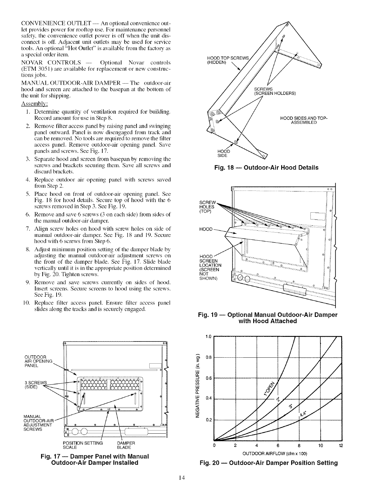
MANUAL OUTDOOR-AIR DAMPER -- The outdoor-air
hood and screen are attached to the basepan at the bottom of
the unit for shipping.
AssemblE;.."
1. Determine quantity of ventilation required for building.
Record amount for use in Step 8.
2. Remove filter access panel by raising panel and swinging
panel outward. Panel is now disengaged from track and
can be removed. No tools are lequiled to remove the filter
access panel. Remove outdoor-tfir opening panel. Save
panels and screws. See Fig. 17.
3. Sepmate hood and screen from basepan by removing the
screws and brackets securing them. Save all screws and
discard brackets.
4. Replace outdoor air opening panel with screws saved
from Step 2.
5. Place hood on front of outdoor-air opening panel. See
Fig. 18 for hood details. Secure top of hood with the 6
screws removed in Step 3. See Fig. 19.
6. Remove and save 6 screws (3 on each side) from sides of
the manual outdoor-air dmnpel:
7. Align screw holes on hood with screw holes on side of
manual outdoor-air dampel: See Fig. 18 and 19. Secure
hood with 6 screws from Step 6.
8. Adjust minimum position setting of the damper blade by
adjusting the manu_d outdoor-air adjustment screws on
the front of the damper blade. See Fig. 17. Slide blade
vertically until it is in the appropriate position determined
by Fig. 20. Tighten screws.
9. Remove and save screws currently on sides of hood.
Insert screens. Secure screens to hood using the screws.
See Fig. 19.
10. Replace filter access panel. Ensure filter access panel
slides _dong the tracks and is securely engaged.
HOOD TOP SCREWS
(HIDDEN)
SCREWS
HOOD SlDESANDTOP-
ASSEMBLED
HOOD
SIDE
Fig. 18- Outdoor-Air Hood Details
SCREW
HOLES -_
(TOP)
HOOD ::::::_
IJ
\i
SCREEN i
ocd,oN
NOT
SHOWN)
Fig. 19- Optional Manual Outdoor-Air Damper
with Hood Attached
OUTDOOR
AIR OPENING
PANEL
3 SCREWS
(SIDE)
MANUAL
ADJUSTMENT
SCREWS
POSITION SETTING DAMPER
SCALE BLADE
Fig. 17 -- Damper Panel with Manual
Outdoor-Air Damper Installed
t3b
w
w
n_
w
>
o
I11
z
1.0
0.8
0.6
/
///
7./ /
0.2 _ ..i "
0 2 4 8 10 12
OUTDOOR AIRFLOW (cfm x 100)
Fig. 20 -- Outdoor-Air Damper Position Setting
14
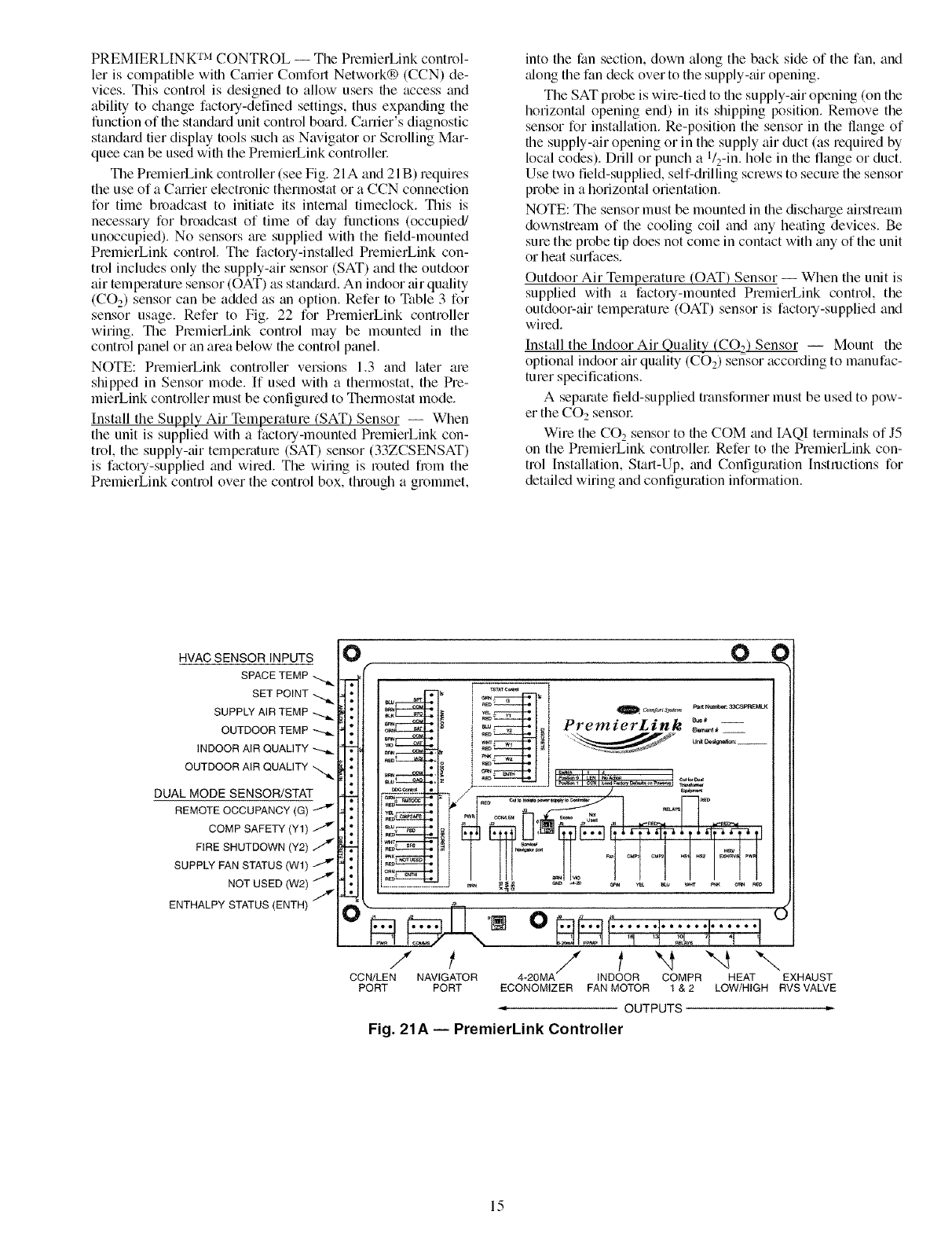
PREMIERLINK TM CONTROL -- The PremierLink control-
let is compatible with Carrier Comfoll Network® (CCN) de-
vices. This control is designed to allow users file access and
ability to change factory-defined settings, thus expanding the
function of file standiu'd unit control board. Career's diagnostic
standard tier display tools such as Navigator or Scrolling Mar-
quee can be used wifll the PmmierLink controflel:
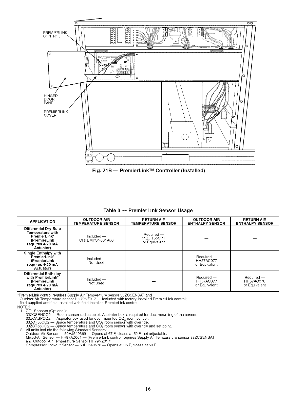
The PremielLink controller (see Fig. 21A and 21 B) requires
the use of a Carrier electronic thermostat or a CCN connection
for time broadcast to initiate its internal timeclock. This is
necessmy for broadcast of time of &ty functions (occupied/
unoccupied). No sensors me supplied with the field-mounted
PremierLink control. The factory-installed PremierLink con-
trol includes only the supply-air sensor (SAT) and the outdoor
air temperature sensor ((-)AT) as stan&trd. An indoor air quality
(CO2) sensor can be added as an option. Refer to Table 3 for
sensor usage. Refer to Fig. 22 for PremierLink controller
wiring. The PmmierLink control may be mounted in file
control panel or an area below the control panel.
NOTE: PmmierLink controller versions 1.3 and later am
shipped in Sensor mode. If used with a fllermostat, the Pre-
mierLink controller must be configured to Themlostat mode.
Install the Supply Air Temperature (SAT) Sensor -- When
the unit is supplied with a factory-mounted PremierLink con-
trol, the supply-air temperature (SAT) sensor (33ZCSENSAT)
is factory-supplied and wired. The wiring is routed from the
PmmierLink control over the control box, through a grommet,
into the fan section, down along the back side of the fan, and
_flong the fan deck over to the supply-air opening.
The SAT probe is wire-tied to file supply-air opening (on the
horizontal opening end) in its shipping position. Remove the
sensor for installation. Re-position the sensor in the flange of
the supply-air opening or in the supply air duct (as required by
local codes). Drill or punch a l/2-in, hole in the flange or duct.
Use two field-supplied, self-drilling screws to secme the sensor
probe in a horizontal orientation.
NOTE: The sensor must be mounted in the dischmge airstream
downstream of the cooling coil and any heating devices. Be
sure the probe tip does not come in contact with any of the unit
or heat surfaces.
Outdoor Air Temperature (OAT) Sensor -- When the unit is
supplied with a factory-mounted PmmierLink control, the
outdoor-air temperature (OAT) sensor is factory-supplied and
wimdi
Install the Indoor Air Quality (CO2.) Sensor -- Mount the
optional indoor air quality (CO2) sensor according to manufac-
turer specifications.
A separate field-supplied transformer must be used to pow-
er the CO2 sensor
Wire file CO_ sensor to the COM and IAQI terminals of J5
on the PremierI_ink controllel: Refer to the PremierLink con-
trol [nstallation, Start-Up, and Configuration [nstructions for
detailed wiring and configuration information.
HVAC SENSOR INPUTS
SPACE TEMP -_
SET POINT -_
SUPPLY AIR TEMP
OUTDOOR TEMP
INDOOR AIR QUALITY -_
OUTDOOR AIR QUALITY
DUAL MODE SENSOR/STAT
REMOTE OCCUPANCY (G)
COMP SAFETY (Y1)
FIRE SHUTDOWN (Y2)
SUPPLY FAN STATUS (W1)
NOT USED (W2)
ENTHALPY STATUS (ENTH) /
O¢
n_ • plm _ 33CSF'RE,_I_
t|'l/'l-Ii
'/ill ...............1"]q 7 I-?']
................_......_.J _ _ & .............
/ / t"4 "-4 "-,,
CCN/LEN NAVIGATOR 4-20MA INDOOR COMPR HEAT EXHAUST
PORT PORT ECONOMIZER FAN MOTOR 1 & 2 LOW/HIGH RVS VALVE
-OUTPUTS
Fig. 21A -- PremierLink Controller
15
PREMIERLINK
CONTROL
©O
HINGED
DOOR
PANEL
PREMIERLINK
COVER
Fig. 21B -- PremierLink TM Controller (Installed)
Table 3 -- PremierLink Sensor Usage
OUTDOOR AIR RETURN AIR OUTDOOR AIR RETURN AIR
APPLICATION TEMPERATURE SENSOR TEMPERATURE SENSOR ENTHALPY SENSOR ENTHALPY SENSOR
Differential Dry Bulb
Temperature with
PremierLink* Included -- Required --
33ZCT55SPT -- --
(PremierLink CRTEMPSN001A00
requires 4-20 mA or Equivalent
Actuator)
Single Enthalpy with
PremierLink* Included -- Required --
(PremierLink Not Used -- HH57AC077 --
requires 4-20 mA or Equivalent
Actuator)
Differential Enthalpy
with PremierLink* Included -- Required -- Required --
(PremierLink Not Used -- HH57AC077 HH57AC078
requires 4-20 mA or Equivalent or Equivalent
Actuator)
*PremierLink control requires Supply Air Temperature sensor 33ZCSENSAT and
Outdoor Air Temperature sensor HH79NZ017 -- included with factory-installed PremierLink control;
field-supplied and field-installed with field-installed PremierLink control.
NOTES:
1. CO2 Sensors (Optional):
33ZCSENCO2 -- Room sensor (adjustable). Aspirator box is required for duct mounting of the sensor.
33ZCASPCO2 -- Aspirator box used for duct-mounted CO2 room sensor.
33ZCT55CO2 -- Space temperature and CO2 room sensor with override.
33ZCT56CO2 -- Space temperature and CO2 room sensor with override and set point.
2. All units include the following Standard Sensors:
Outdoor-Air Sensor -- 50HJ540569 -- Opens at 67 F, closes at 52 F, not adjustable.
Mixed-Air Sensor- HH97AZ001 -- (PremierLink control requires Supply Air Temperature sensor 33ZCSENSAT
and Outdoor Air Temperature Sensor HH79NZ017)
Compressor Lockout Sensor -- 50HJ540570 -- Opens at 35 F, closes at 50 E
16
PNK
VJO
YEL
£LU
............._ _BLK
RED
£LU
YEL
ii WHT
......:F-<
CON
Comm
i L BLK
Economi$er2 [ RED , i
4- 20mA { i
- i URN
ENTHALPY
i SENSOR
REDBR N J
PNK
RED _,
7(][) .............WHT............................................................................................................
8ql -- BLK
LEGEND
COMMS -- Communications
OAT -- Outdoor Air Temperature Sensor
PWR -- Power
RTU -- Rooftop Unit
SAT -- Supply Air Temperature Sensor
TB -- Terminal Block
3(/15
ilL/'
6(]]_G
\jjj_
7r/i-, C
_\ ILl
8/r_,X
RTU Terminal
Board
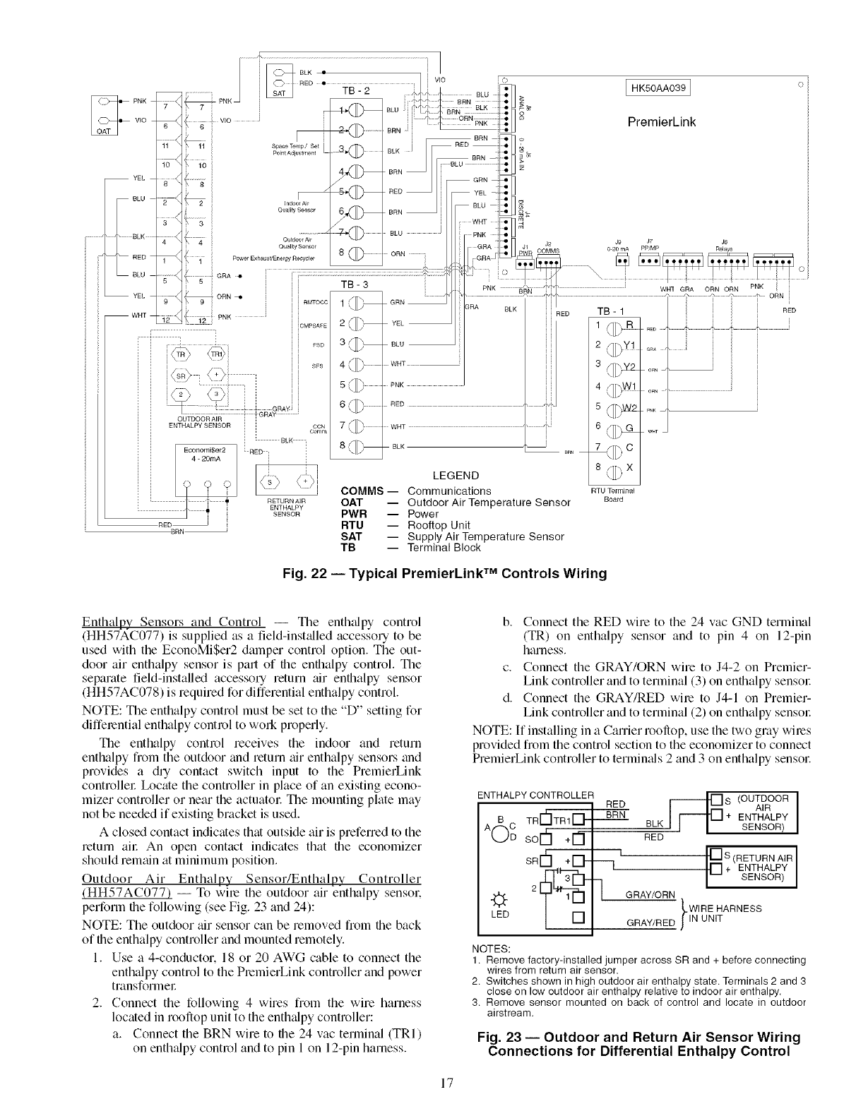
Fig. 22 -- Typical PremierLink TM Controls Wiring
HK50AA039 I
PremierLink
i i
ORN
ORN ...................................................
PN_
W_T
Enthalpy Sensors and Control -- The enthfflpy control
(HH57AC077) is supplied as a field-instfdled accessory to be
used with the EconoMi$er2 damper control option. The out-
door air enthalpy sensor is pall of file enfllalpy control. The
separate field-installed accessory return air enthalpy sensor
(HH57AC078) is required for differential enthalpy control.
NOTE: The enthalpy control must be set to the "D" setting for
differential enthalpy control to work properly.
The enthalpy control receives the indoor and return
enthalpy fiom the outdoor find return air enthalpy sensors and
provides a dry contact switch input to the PremierLink
controllel: Ix_cate the controller in place of an existing econo-
mizer controller or near the actuatol: The mounting plate may
not be needed if existing bracket is used.
A closed contact indicates that outside air is preferred to the
return ail: An open contact indicates that file economizer
should remfdn fit minimum position.
Outdoor Air Enthalpy Sensor/Enthalpy Controller
(HH57AC077) -- To wire the outdoor air enthalpy sensok
perform file following (see Fig. 23 and 24):
NOTE: The outdoor air sensor can be removed from the back
of file enthalpy controller and mounted remotely.
1. Use a 4-conductor, 18 or 20 AWG cable to connect the
enthalpy control to the PremierLink controller and power
transforme£
2. Connect the following 4 wires from the wire harness
located in rooftop unit to the enthzdpy controller:
a. Connect the BRN wire to file 24 vac terminal (TRI)
on enth_dpy control and to pin 1 on 12-pin harness.
b. Connect the RED wire to the 24 vac GND terminal
(TR) on enthalpy sensor and to pin 4 on 12-pin
harness.
c. Connect the GRAY/ORN wire to J4-2 on Premier-
Link controller and to terminal (3) on enthalpy sensol:
d. Connect the GRAY/RED wire to J4-1 on Premier-
Link controller and to terminal (2) on enthalpy sensol:
NOTE: If installing in a Carrier rooliop, use the two gray wiles
provided from the control section to the economizer to connect
PremierLink controller to termimds 2 and 3 on enthalpy sensol:
ENTHALPY CONTROLLER
RED
A(_C TR Fa"ITR 1[_- BRN
sorh +[3-
SRI-h+H- -q
LED
lOUTOOORI
AIR
ENTHALPY
BLK SENSOR)
RED
I [] S (RETURN AIR
[] + ENTHALPY
SENSOR)
GRAY/ORN
_WIRE HARNESS
GRAY/RED JlN UNIT
NOTES:
1. Remove factory-installed jumper across SR and + before connecting
wires from return air sensor
2. Switches shown in high outdoor air enthalpy state. Terminals 2 and 3
close on low outdoor air enthalpy relative to indoor air enthalpy,
3. Remove sensor mounted on back of control and locate in outdoor
airstream.
Fig. 23 -- Outdoor and Return Air Sensor Wiring
Connections for Differential Enthalpy Control
17
HH57AC077
ENTHALPY
CONTROL AND
OUTDOOR AIR
ENTHALPY SENSOR
o o
HH57AC078 ENTHALPY
SENSOR (USED WITH
ENTHALPY CONTROL
FOR DIFFERENTIAL
ENTHALPY OPERATION)
MOUNTING PLATE
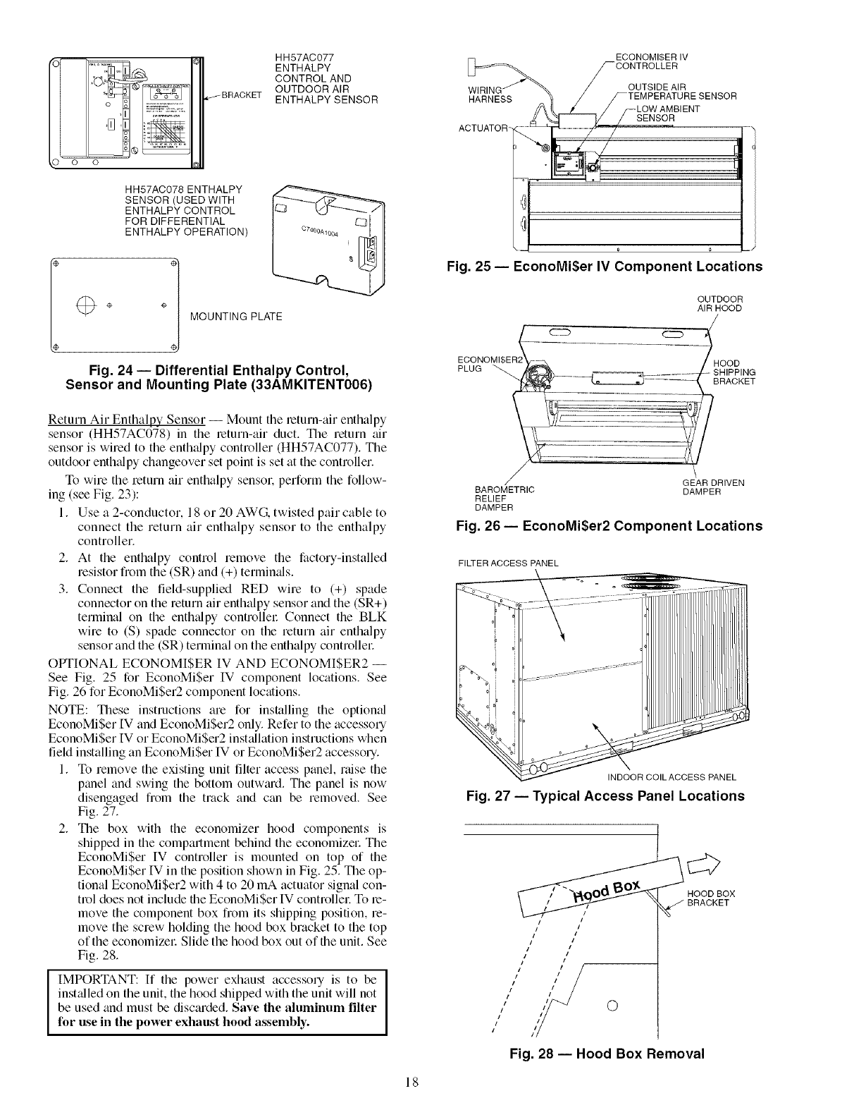
Fig. 24 -- Differential Enthalpy Control,
Sensor and Mounting Plate (33AMKITENT006)
ACTUATOR-
ECONOMI$ER IV
-CONTROLLER
OUTSIDE AIR
Fig. 25 -- EconoMi$er IV Component Locations
OUTDOOR
AIR HOOD
ECONOMI
PLUG -SHIPPING
BRACKET
Return Air Enthalpy Sensor -- Mount the return-air enthalpy
sensor (HH57AC078) in the return-air duct. The return air
sensor is wired to the enthalpy contrDller (HH57AC077). The
outdoor enthalpy changeover set point is set at the contrDller.
To wire the return air enthalpy sensol: perform the follow-
ing (see Fig. 23):
1. Use a 2-conductor, 18 or 20 AWG. twisted pail cable to
connect the return air enthalpy sensor to the enthalpy
controller.
2. At the enthalpy control remove the factory-installed
resistor from the (SR) and (+) termimds.
3. Connect the field-supplied RED wire to (+) spade
connector on the return air enthalpy sensor and the (SR+)
terminal on the enthalpy contrDllel: Connect the BLK
wire to (S) spade connector on the return air enthalpy
sensor and the (SR) terminal on the enthalpy contrDllel:
OPTIONAL ECONOMISER IV AND ECONOMISER2 --
See Fig. 25 for EconoMiSer IV component locations. See
Fig. 26 for EconoMi$er2 component locations.
NOTE: These instructions are for insUdling the optional
EconoMi$er IV and EconoMiSer2 only. Refer to the accessory
EconoMiSer IV or EconoMiSer2 inst_dlation instructions when
field installing an EconoMiSer IV or EconoMiSer2 accessory.
1. To remove the existing unit filter access panel, raise the
panel and swing the bottom outw;ud. The panel is now
disengaged from the track and can be removed. See
Fig. 27.
2. The box with the economizer hood components is
shipped in the compartment behind the economizel: The
EconoMiSer IV contrDller is mounted on top of the
EconoMi$er IV in the position shown in Fig. 25. The op-
tional EconoMiSer2 with 4 to 20 mA actuator signal con-
trol does not include the EconoMiSer IV contrDllel: To le-
move the component box from its shipping position, re-
move the screw holding the hood box bracket to the top
of the economizel: Slide the hood box out of the unit. See
Fig. 28.
IMPORTANT: If the power exhaust accessory is to be I
inst_dled on the unit, the hood shipped with the unit will not I
be used and must be discarded. Save the aluminum filter
for use in the power exhaust hood assembly.
GEAR DRIVEN
BAROMETRIC DAMPER
RELIEF
DAMPER
Fig. 26 -- EconoMi$er2 Component Locations
FILTER ACCESS PANEL
INDOOR COILACCESS PANEL
Fig. 27 -- Typical Access Panel Locations
iI 111 /
I1 111/_
11 / 0
i I i I
i I
/
Fig. 28 -- Hood Box Removal
18
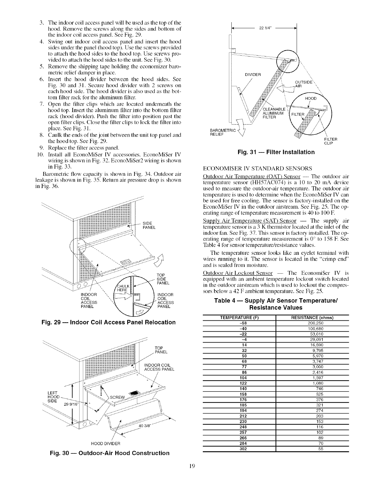
3. The indoor coil access panel will be used as the top of the
hood. Remove the screws along the sides and bottom of
the indoor coil access panel. See Fig. 29.
4. Swing out indoor coil access panel and insert the hood
sides under the panel (hood top). Use the sclews provided
to attach the hood sides to the hood top. Use screws pro-
vided to attach the hood sides to the unit. See Fig. 30.
5. Remove the shipping tape holding the economizer baro-
metric relief damper in phtce.
6. Insert the hood divider between the hood sides. See
Fig. 30 and 31. Secure hood divider with 2 screws on
each hood side. The hood divider is also used as the bot-
tom filter rock for file aluminum filter.
7. Open the filter clips which are located underneath the
hood top. Insert the aluminum filter into the bottom filter
rack (hood divider). Push file filter into position past the
open filter clips. Close the filter clips to lock the tilter into
place. See Fig. 31.
8. Caulk the ends of the joint between the unit top panel and
the hood top. See Fig. 29.
9. Replace the filter access panel.
10. Install all EconoMi$er IV accessories. EconoMiSer IV
wiling is shown in Fig. 32. EconoMi$er2 wiling is shown
in Fig. 33.
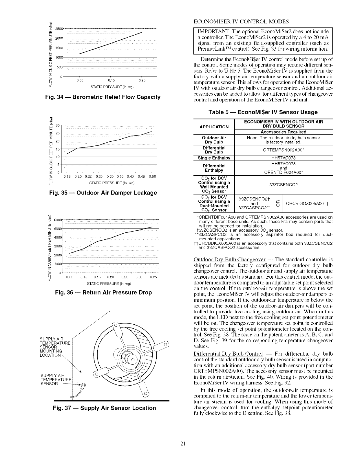
Barometric flow capacity is shown in Fig. 34. Outdoor air
leakage is shown in Fig. 35. Return air pressure drop is shown
in Fig. 36.
SIDE
PANEL
\\
_. TOP
SIDE
PANEL
INDOOR ', INDOOR
COIL "', COIL
ACCESS
PANEL PANEL
ALUMINUM
FILTER
BAROMETRIC ,
RELIEF
Fig. 31 -- Filter Installation
FILTER
CLIP
ECONOMISER IV STANDARD SENSORS
Outdoor Air Temperature (OAT) Sensor -- The outdoor air
temperature sensor (HH57AC074) is a 10 to 20 mA device
used to measure the outdoor-air temperature. The outdoor air
temperature is used to determine when the EconoMiSer IV can
be used for free cooling. The sensor is factory-installed on the
EconoMi$er IV in the outdoor airstream. See Fig. 25. Tile op-
erating range of temperature measurement is 40 to 100 E
Supply Air Tempelature (SAT) Sensor -- The supply air
temperature sensor is a 3 K thermistor located at the inlet of the
indoor fan. See Fig. 37. This sensor is factory installed. Tile op-
erating range of temperature measurement is 0 ° to 158 F. See
Table 4 for sensor temperature/resistance values.
The temperature sensor looks like an eyelet terminal with
wires running to it. The sensor is located in the "crimp end"
and is sealed from moisture.
Outdoor Air Lockout Sensor -- The EconomiSer IV is
equipped with an mnbient temperature lockout switch located
in the outdoor airstream which is used to lockout the compres-
sors below a 42 F ambient temperature. See Fig. 25.
Table 4 -- Supply Air Sensor Temperature/
Resistance Values
Fig. 29 -- Indoor Coil Access Panel Relocation
TOP
j PANEL
INDOOR COIL
ACCESS PANEL
LEFT
SIDE
HOOD DIVIDER
Fig. 30 -- Outdoor-Air Hood Construction
TEMPERATURE (F) RESISTANCE (ohms)
-58 200,250
-40 100,680
-22 53,010
-4 29,091
14 16,590
32 9,795
50 5,970
68 3,747
77 3,000
86 2,416
104 1,597
122 1,080
140 746
158 525
176 376
185 321
194 274
212 203
230 153
248 116
257 102
266 89
284 70
302 55
19
FOR OCCUPANCY CONTROL
REPLACE JUMPER WITH
., FIELD-SUPPLIED TIME CLOCK
/
L _
FIELD SPLICE
TAN
LEGEND
TO PWR EXHAUST
ACCESSORY
Potentiometer Defaults Settings: NOTES:
(_L}(
ECONOMIZER MOTOR
BLf(
--GRYJ
BLU
mELD SPLICE
BRN
(_OT
(NOT
DCV-- Demand Controlled Ventilation
IAQ -- Indoor Air Quality
LA -- Low Ambient Lockout Device
OAT-- Outdoor-Air Temperature
POT-- Potentiometer
RAT-- Return-Air Temperature
(_0f USES)
GRY
ORG
(_01USEO}
Power Exhaust Middle
Minimum Pos. Fully Closed
DCV Max. Middle
DCV Set Middle
Enthalpy C Setting
PL6"R
USEO) I_
USED) I_
<
<
4
:t
1. 620 ohm, 1 watt 5% resistor should be removed only when using differential
enthalpy or dry bulb.
2. If a separate field-supplied 24 v transformer is used for the IAQ sensor power
supply, it cannot have the secondary of the transformer grounded.
3. For field-installed remote minimum position POT, remove black wire jumper
between P and P1 and set control minimum position POT to the minimum
position.
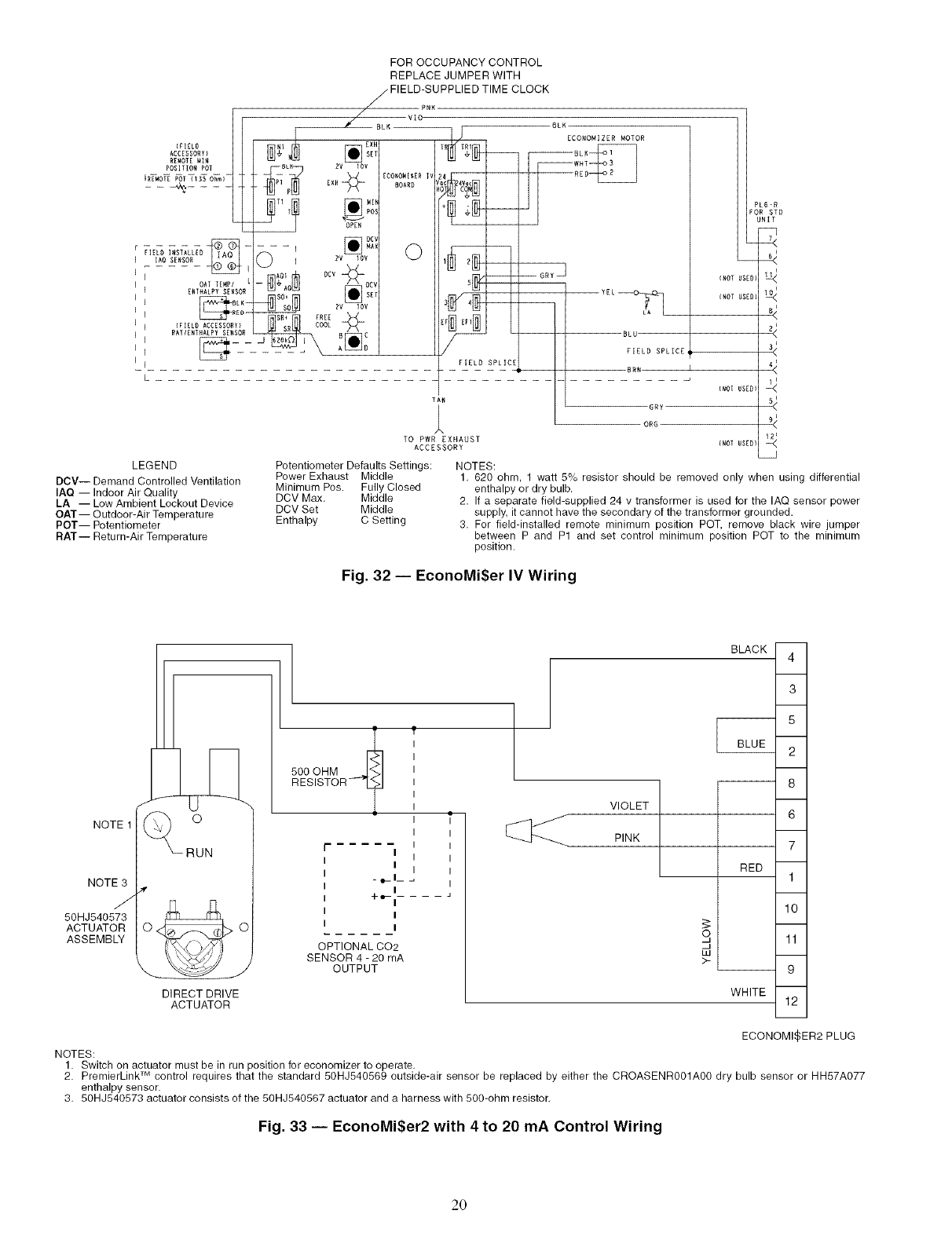
Fig. 32 -- EconoMi$er IV Wiring
NOTE 1
NOTE3
J
50HJ540573
ACTUATOR
ASSEMBLY
RUN
DIRECT DRIVE
ACTUATOR
BLACK
500 OHM
RESISTOR-'?
r i
I
-e_l_
I
+'-I
i
I
OPTIONAL CO2
SENSOR 4 - 20 mA
OUTPUT
VIOLET
PINK
RED
S
W
>-
WHITE
4
3
5
2
8
6
7
1
10
11
9
12
ECONOMIZER2 PLUG
NOTES:
1. Switch on actuator must be in run position for economizer to operate.
TM
2. PremierLink control requires that the standard 50HJ540569 outside-air sensor be replaced by either the CROASENR001A00 dry bulb sensor or HH57A077
enthalpy sensor.
3. 50HJ540573 actuator consists of the 50HJ540567 actuator and a harness with 500-ohrn resistor.
Fig. 33 -- EconoMi$er2 with 4 to 20 mA Control Wiring
20
2500
z 2000
tiff
1500
1000
LL
O
500
0
_z
S
LL
0.05 0.15 0.25
STATIC PRESSURE (in. wg)
Fig. 34 -- Barometric Relief Flow Capacity
30- "xzzzzzzzzzzzzzzzzzzzzzz z!
25 _
2o
o_
15
w
LL 10
_o
m 5
O
_z 0
0.13 0.20 0.22 0.25 0.30 0.35 0.40 0.45 0.50
_I STATIC PRESSURE (in. wg)
LL
Fig. 35 -- Outdoor Air Damper Leakage
_o 600C_
5000
4000
o2005
lOOO
z
0 ' i , r ,i , i , r , i , i
O 0.05 0.10 0.15 0.20 0.25 0.30 0.35
LL
STATIC PRESSURE (in. wg)
Fig. 36 -- Return Air Pressure Drop
SUPPLY AIR
TEMPERATURE
SENSOR
MOUNTING
LOCATION
\
SUPPLY AIR
TEMPERATURE
SENSOR _
Fig. 37 -- Supply Air Sensor Location
ECONOMISER IV CONTROL MODES
IIMPORTANT: The optional EconoMiSer2 does not include ]
a controllec The EconoMiSer2 is operated by a 4 to 20 mA I
signal from an existing field-supplied controller (such as
PremierLink TM control). See Fig. 33 for wiring information.
Determine the EconoMiSer Wcontrol mode before set up of
the contl_ol. Some modes of operation may lequire different sen-
sors. Refer to Table 5. The EconoMiSer IV is supplied from file
factory with a supply air temperature sensor and an outdoor air
temperature sensoc This allows for operation of the EconoMi$er
IV with outdoor air chy bulb changeover control. Additiomd ac-
cessories can be added to _dlow for different types of changeover
control and operation of the EconoMiSer IV and unit.
Table 5 -- EconoMi$er IV Sensor Usage
APPLICATION
Outdoor Air
Dry Bulb
Differential
Dry Bulb
Single Enthalpy
Differential
Enthalpy
CO2 for DCV
Control using a
Wall-Mounted
CO2 Sensor
CO2 for DCV
Control using a
Duct-Mounted
CO2 Sensor
ECONOMI$ER IV WITH OUTDOOR AIR
DRY BULB SENSOR
Accessories Required
None. The outdoor air dry bulb sensor
is factory installed.
CRTEMPSN002A00*
HH57AC078
HH57AC078
and
CRENTDIF004A00*
33ZCSENCO2
33ZCSENCO21-
and CRCBDIOX005A001-1-
33ZCASPCO2**
*CRENTDIF004A00 and CRTEMPSN002A00 accessories are used on
many different base units. As such, these kits may contain parts that
will not be needed for installation.
1-33ZCSENCO2 is an accessory CO 2 sensor.
**33ZCASPCO2 is an accessory aspirator box required for duct-
mounted applications.
1-1-CRCBDIOX005A00 is an accessory that contains both 33ZCSENCO2
and 33ZCASPCO2 accessories.
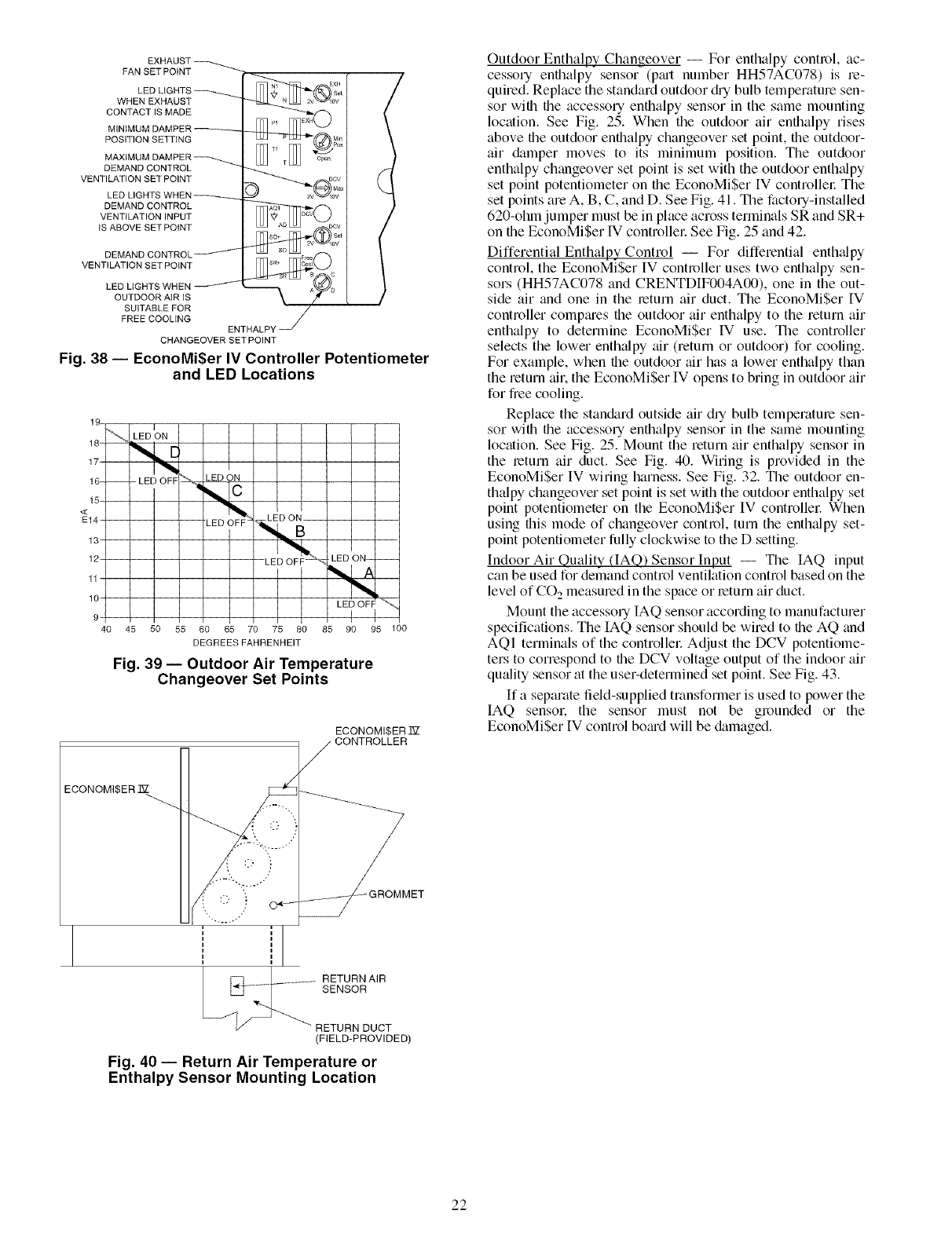
Outdoor DLy Bulb Changeover -- The standald controller is
shipped from the factory configured for outdoor dry bulb
changeover control. The outdoor air and supply air temperature
sensors tue included as stan&u'd. For this control mode, file out-
door temperature is compared to an adjustable set point selected
on file control. If the outdoor-air temperature is above the set
point, the EconoMi$er IV will adjust file outdoor-air dampers to
minimum position. If the outdoor-air temperature is below the
set point, the position of the outdoor-air &unpel.s will be con-
trolled to provide free cooling using outdoor aic When in this
mode, file LED next to file free cooling set point potentiometer
will be on. The changeover temperature set point is controlled
by the free cooling set point potentiometer located on file con-
trol. See Fig. 38. The sc_de on the potentiometer is A, B, C, and
D. See Fig. 39 for the conesponding temperature changeover
values.
Differential Dry Bulb Control -- For differential dry bulb
control file standard outdoor chy bulb sensor is used in conjunc-
tion with an additional accessory dry bulb sensor (part number
CRTEMPSN002A00). The accessoq sensor must be mounted
in the return airstream. See Fig. 40. Wiring is provided in the
EconoMi$er IV wiring htuness. See Fig. 32.
In this mode of operation, the outdoor-air temperature is
compared to the return-air temperature and the lower tempera-
ture air stremn is used for cooling. When using this mode of
changeover control, turn the enthalpy setpoint potentiometer
fully clockwise to the D setting. See Fig. 38.
21
EXHAUST
FAN SET POINT
LED LIGHTS
WHEN EXHAUST
CONTACT IS MADE
MINIMUM DAMPER
POSITION SETTING
MAXIMUM DAMPER
DEMAND CONTROL
VENTILATION SET POINT
LED LIGHTS WHEN_
DEMAND CONTROL
VENTILATION INPUT
tS ABOVE SET POINT
DEMAND CONTROL
VENTILATION SET POINT
LED LIGHTS WHEN
OUTDOOR AiR IS
SUITABLE FOR
FREE COOLING
ENTHALPY
CHANGEOVER SET POINT
Fig. 38 -- EconoMi$er IV Controller Potentiometer
and LED Locations
19.
17-
16- -- - LED OFF
15-
<
E14-
13"
12-
11-
10-
9-i
4O
LED ON
LED OFF- , LED O;
45 50 55 60 65 70 75 80
DEGREES FAHRENHEIT
I
LED ON-- --
LED_oFAF'_...,
I
85 90 95 100
Fig. 39 -- Outdoor Air Temperature
Changeover Set Points
ECONOMI$ER T_7
Outdoor Enthalpy Changeover -- For enthalpy control, ac-
cessory enthalpy sensor (p_ut number HH57AC078) is re-
quired. Replace the standard outdoor @ bulb temperature sen-
sor with file accessory enthalpy sensor in the same mounting
location. See Fig. 25. When the outdoor air enfllalpy rises
above the outdoor enthalpy changeover set point, file outdoor-
air damper moves to its minimum position. Tile outdoor
enthalpy changeover set point is set with the outdoor enth_dpy
set point potentiometer on the EconoMi$er IV controllel: The
set points are A, B, C, and D. See Fig. 41. The factory-installed
620-ohln jumper must be in place across terminals SR and SR+
on the EconoMiSer IV controllel: See Fig. 25 and 42.
Differential Enthalpy Control -- For differential enth_dpy
control, the EconoMiSer IV controller uses two enthalpy sen-
sors (HH57AC078 and CRENTDIF004A00), one in the out-
side air and one in the return air duct. The EconoMiSer IV
controller compmes file outdoor air enthalpy to the return air
enthalpy to determine EconoMiSer IV use. The controller
selects the lower enthalpy air (return or outdoor) for cooling.
For example, when the outdoor air has a lower enthalpy than
the return air. the EconoMiSer IV opens to bring in outdoor air
for free cooling.
Replace the standard outside air din bulb temperature sen-
sor with the accessory enthalpy sensor in the same mounting
location. See Fig. 25. Mount the return air enthalpy sensor in
the leturn air duct. See Fig. 40. Wiring is provided in the
EconoMiSer IV wiring harness. See Fig. 32. The outdoor en-
thalpy changeover set point is set with the outdoor enthalpy set
point potentiometer on the EconoMiSer IV controllel: When
using this mode of changeover control, turn the enth_flpy set-
point potentiometer fully clockwise to the D setting.
Indoor Air Quality (IAQ) Sensor Input -- The IAQ input
can be used for demand control ventilation control based on the
level of CO 2 measured in the space or return air duct.
Mount the accessory IAQ sensor according to manufacturer
specifications. The IAQ sensor should be wired to the AQ and
AQI terminals of the controllel: Adjust the DCV potentiome-
ters to correspond to the DCV voltage output of the indoor air
qu_dity sensor fit the user-determined set point. See Fig. 43.
If a separate field-supplied transformer is used to power the
IAQ sensol: the sensor must not be grounded or the
EconoMiSer IV control bo_ud will be &imaged.
Fig. 40 -- Return Air Temperature or
Enthalpy Sensor Mounting Location
22
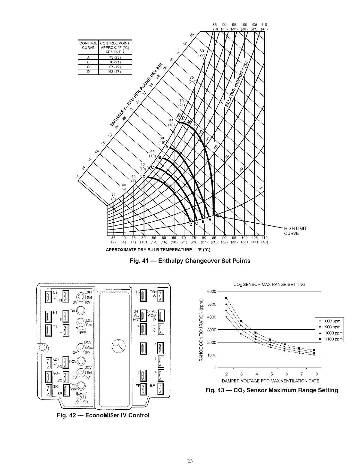
CONTROL CONTROL POINT
CURVE APPROX. °F (°C)
AT 50% RH
A 73 (23)
B 70 (21)
C 67 (19)
D 63 (17)
HIGH LIMIT
\ CURVE
35 40 45 50 55 60 65 70 75 80 85 90 95 180 105 110
(2) (4) (7) (10) (13) (16) (18) (21) (24) (27) (29) (32) (35) (38) (41) (43)
o o
APPROXIMATE DRY BULB TEMPERATURE iF (C)
Fig. 41 -- Enthalpy Changeover Set Points
q-b,
1/,/
E
Set
N 2 OV
P1 r_EX_
P_l_Jl (_'_ Min
T1 E-] _.os
T _l_Jl Open
Aol IT]oov_
_AQ _l_Jl -- DCV
s°+ N 2v_ov e'
so _l_JI
SR+ Free
r oo,©
sRu _lb-_c
.
24T_24 Va_
Vac COM
HO
11 2
6
4
EF B EF1
¢
Fig. 42 -- EconoMi$er IV Control
z
_o
cc
LT_
Z
8
LU
(D
Z
<
CC
6000
5000
4000
3000
2000
1000
0
CO2 SENSOR MAX RANGE SETTING
2 345678
DAMPER VOLTAGE FOR MAX VENTILATION RATE
Fig. 43 -- C02 Sensor Maximum Range Setting
23
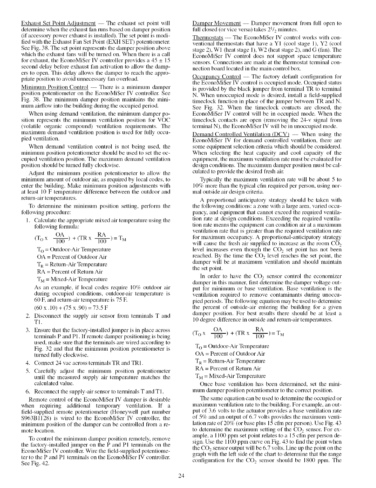
Exhaust Set Point Adjustment -- The exhaust set point will
determine when the exhaust fan runs based on dmnper position
(if accessory power exhaust is installed). The set point is modi-
fied with the Exhaust Fan Set Point (EXH SET) potentiometer
See Fig. 38. The set point represents the damper position above
which the exhaust fans will be turned on. When there is a call
for exhaust, the EconoMiSer IV controller provides a 45 _+15
second delay before exhaust fan activation to allow the damp-
ers to open. This delay _fllows file damper to reach the appro-
priate position to avoid unnecessary fan overload.
Minimum Position Control -- There is a minimum damper
position potentiometer on the EconoMiSer [V controllel: See
Fig. 38. The minimum damper position maintains the mini-
mum airflow into the building during the occupied period.
When using demand ventihttion, the minimum dmnper po-
sition represents the minimum ventilation position for VOC
(volatile organic compound) ventilation requirements. The
maximum demand ventilation position is used for fully occu-
pied ventilation.
When demand ventilation control is not being used, the
minimum position potentiometer should be used to set the oc-
cupied ventilation position. The maximum demand ventilation
position should be turned fully clockwise.
Adjust the minimum position potentiometer to allow the
minimum mnount of outdoor aik as required by local codes, to
enter the building. Make minimum position adjustments with
at least 10 F temperature difference between the outdoor and
return-air temperatures.
To determine the minimum position setting, perform the
following procedure:
1. Calculate the appropriate mixed air temperature using the
following formula:
OA RA
(To x l-Tiff) + (TR x l-Tiff) = TM
To = Outdoor-Air Temperature
OA = Percent of Outdoor Air
TR = Return-Air Temperature
RA = Percent of Return Air
TM = Mixed-Air Temperature
As an example, if local codes require 10% outdoor _dr
during occupied conditions, outdoor-air temperature is
60 E and return-air temperature is 75 E
(60 x .10) + (75 x .90) =73.5 F
2. Disconnect the supply air sensor from terminals T and
TI.
3. Ensure that the factory-installed jumper is in place across
terminals P and PI. If remote damper positioning is being
used, make sure that the terminals are wired according to
Fig. 32 and that the minimum position potentiometer is
turned fully clockwise.
4. Connect 24 vac across terminals TR and TRI.
5. Carelhlly adjust the minimum position potentiometer
until the measured supply air temperature matches the
calculated value.
6. Reconnect the supply-air sensor to terminals T and Tl.
Remote control of the EconoMiSer IV damper is desirable
when requiring additiomfl tempormy ventilation. If a
field-supplied remote potentiometer (Honeywell part number
$963B1128) is wired to the EconoMiSer IV controllek the
minimum position of the damper can be controlled from a re-
mote location.
To control the minimum damper position remotely, remove
the factory-installed jumper on the P and PI terminals on the
EconoMiSer IV controllel: Wire the field-supplied potentiome-
ter to the P and PI terminals on the EconoMi$er IV controller.
See Fig. 42.
Damper Movement -- Damper movement trom full open to
full closed (or vice versa) takes 2112minutes.
Thermostats -- The EconoMi$er IV control works with con-
ventiomd thermostats that have a YI (cool stage 1), Y2 (cool
stage 2), Wl (heat stage 1), W2 (heat stage 2), and G (fan). The
EconoMi$er IV control does not support space temperature
sensors. Connections are made at the thermostat termimd con-
nection board located in the main control box.
Occupancy Control -- The factoUdefault configuration for
the EconoMi$er IV control is occupied mode. Occupied status
is provided by the black jumper fiom terminal TR to terminal
N. When unoccupied mode is desired, inst_dl a field-supplied
timeclock function in place of the jumper between TR and N.
See Fig. 32. When the timeclock contacts are closed, the
EconoMi$er IV control will be in occupied mode. When the
timeclock contacts are open (removing the 24-v signal from
terminal N), the EconoMi$er IV will be in unoccupied mode.
Demand Controlled Ventilation (DCV) -- When using the
EconoMi$er IV for demand controlled ventilation, them are
some equipment selection criteria which should be considered.
When selecting the heat capacity and cool capacity of the
equipment, the maximum ventilation rote must be evaluated for
design conditions. The maximum damper position must be cal-
culated to provide the desired fresh air
Typically the maximum ventilation rate will be about 5 to
10% morn than the typical cfin required per person, using nor-
mid outside air design criteria.
A proportional anticipatory strategy should be taken with
the following conditions: a zone with a large area, varied occu-
pancy, and equipment that cannot exceed the required ventila-
tion rate at design conditions. Exceeding the required ventila-
tion rate means the equipment can condition air at a maximum
ventilation rate that is greater than the required ventilation rate
for maximum occupancy. A proportional-anticipato Ustrategy
will cause the fresh air supplied to increase as the room CO2
level increases even though the CO2 set point has not been
reached. By the time the CO2 level roaches the set point, the
damper will be at maximum ventilation and should maintain
the set point.
In order to have the CO 2 sensor control the economizer
damper in this manner, fil.'stdetermine the damper voltage out-
put for minimum or base ventilation. Base ventilation is the
ventilation required to remove contmninants during unoccu-
pied periods. The following equation may be used to determine
the percent of outside-air entering the building for a given
damper position. For best results there should be at least a
10 degree difference in outside and return-air temperatures.
OA RA
(To x l-Tiff) + (TR x l-Tiff) = TM
To = Outdoor-Air Temperature
OA = Percent of Outdoor Air
TR= Return-Air Temperature
RA = Percent of Return Air
TM= Mixed-Air Temperature
Once base ventilation has been determined, set the mini-
mum damper position potentiometer to the correct position.
The same equation can be used to deterlnine the occupied or
maximum ventilation rate to the building. For example, an out-
put of 3.6 volts to the actuator provides a base ventilation rate
of 5% and an output of 6.7 volts provides the maximum venti-
lation rate of 20% (or base plus 15 cfm per person). Use Fig. 43
to determine the maximum setting of the CO 2 sensol: For ex-
ample, a 1100 ppm set point relates to a 15 cfm per person de-
sign. Use the 1100 ppm curve on Fig. 43 to find the point when
the CO2 sensor output will be 6.7 volts. Line up the point on the
graph with the left side of the chart to determine that the range
configuration for the CO 2 sensor should be 1800 ppm. The
24
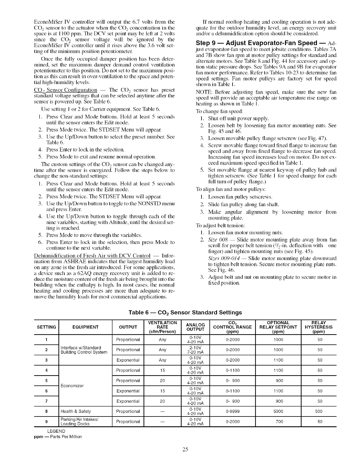
EconoMiSerIVcontrollerwilloutputthe6.7voltsfiomthe
COesensortotheactuatorwhentheCO2concentrationinthe
spaceisat1100ppm.TheDCVsetpointmaybeleftat2volts
sincethe CO2 sensorvoltagewill be ignoredby the
EconoMiSerIVcontrolleruntilitrisesabovethe3.6voltset-
tingoftheminimumpositionpotentiometer
Oncethefullyoccupieddmnperpositionhasbeendeter-
mined,setfilemaximumdamperdemandcontrolventilation
potentiometertothisposition.Donotsettothemaximumposi-
tionasthiscanresultinover-ventihttiontothespaceandpoten-
tialhigh-humiditylevels.
CO__,Sensor Configuration -- The CO e sensor has preset
standard voltage settings that can be selected anytime after the
sensor is powered up. See Table 6.
Use setting 1 or 2 for Carrier equipment. See Table 6.
1. Press Clear and Mode buttons. Hold at least 5 seconds
until the sensor enters the Edit mode.
2. Press Mode twice. The STDSET Menu will appem:
3. Use the Up/Down button to select the preset numbel: See
Table 6.
4. Press Enter to lock in the selection.
5. Pleas Mode to exit and resume norm_d operation.
The custom settings of the CO e sensor can be changed any-
time after the sensor is energized. Follow the steps below to
change the non-stan&_rd settings:
1. Press Clear and Mode buttons. Hold at least 5 seconds
until the sensor enters the Edit mode.
2. Press Mode twice. The STDSET Menu will appem:
3. Use the Up/Down button to toggle to the NONSTD menu
and press Entel:
4. Use the Up/Down button to toggle through each of the
nine variables, stinting with Altitude, until the desired set-
ting is reached.
5. Press Mode to move through the variables.
6. Press Enter to lock in the selection, then press Mode to
continue to the next v;uiable.
Dehumidification of Fresh Air with DCV Control -- Infor-
mation from ASHRAE indicates that the largest humidity load
on any zone is the fresh air introduced. For some applications,
a device such as a 62AQ energy recovery unit is added to re-
duce the moisture content of the fresh air being brought into the
building when the enthalpy is high. [n most cases, the norln_fl
heating and cooling processes are morn than adequate to re-
move the humidity loads for most commerci_fl applications.
If normal rooftop heating and cooling operation is not ade-
quate for the outdoor humidity level, an energy recovery unit
and/or a dehumidification option should be considered.
Step 9 -- Adjust Evaporator-Fan Speed -- Ad-
just evaporator-fan speed to meet jobsite conditions. Tables 7A
and 7B show fan rpm at motor pulley settings for standard and
_flternate motors. See Table 8 and Fig. 44 for accessory and op-
tion static pressure diops. See Tables 9A and 9B for evaporator
fan motor performance. Refer to Tables 10-23 to determine fan
speed settings. Fan motor pulleys are factory set for speed
shown in Table 1.
NOTE: Befole adjusting fan speed, make sure the new fan
speed will provide an acceptable air temperature rise range on
heating as shown in Table 1.
To change fan speed:
1. Shut offunit power supply.
2. Ix_osen belt by loosening fan motor mounting nuts. See
Fig. 45 and 46.
3. Ix_osen movable pulley flange setscrew (see Fig. 47).
4. Screw movable flange toward fixed flange to increase fan
speed and away from fixed flange to decrease fan speed.
Increasing fan speed increases load on motol: Do not ex-
ceed maximum speed specified in Table 1.
5. Set movable flange at nearest keyway of pulley hub and
tighten setscrew. (See Table 1 for speed change for each
lull turn of pulley flange.)
To align fan and motor pulleys:
1. Ix_osen fan pulley setscrews.
2. Slide fan pulley along fan shaft.
3. Make anguhu" alignment by loosening motor from
mounting plate.
To adjust belt tension:
1. Ix_osen fan motor mounting nuts.
2. Si'..e 008 -- Slide motor mounting plate away from fan
scroll for proper belt tension (l/2-in. deflection with one
linger) and tighten mounting nuts (see Fig. 45).
Sizes 009-014 -- Slide motor mounting plate downward
to tighten belt tension. Secure motor mounting plate nuts.
See Fig. 46.
3. Adjust bolt and nut on mounting plate to secure motor in
fixed position.
Table 6 -- CO 2 Sensor Standard Settings
OUTPUTSETTING
1
2
3
4
5
6
7
8
EQUIPMENT
Interface w/Standard
Building Control System
Economizer
Health & Safety
9 Parking/Air Intakes/
Loading Docks
LEGEND
ppm -- Parts Per Million
Proportional
Proportional
Exponential
Proportional
Proportional
Exponential
Exponential
Proportional
Proportional
VENTILATION
RATE
(cfm/Person)
Any
Any
Any
15
20
15
2O
ANALOG
OUTPUT
0-10V
4-20 mA
2-10V
7-20 mA
0-10V
4-20 mA
0-10V
4-20 mA
0-10V
4-20 mA
0-10V
4-20 mA
0-10V
4-20 mA
0-10V
4-20 mA
0-10V
4-20 mA
002
CONTROLRANGE
(ppm)
0-2000
0-2000
0-2000
0-1100
0- 900
0-1100
0- 900
0-9999
0-2000
OPTIONAL
RELAY SETPOINT
(ppm)
1000
1000
1100
1100
900
1100
900
5000
700
RELAY
HYSTERESIS
(ppm)
5O
5O
5O
5O
5O
5O
5O
5OO
5O
25
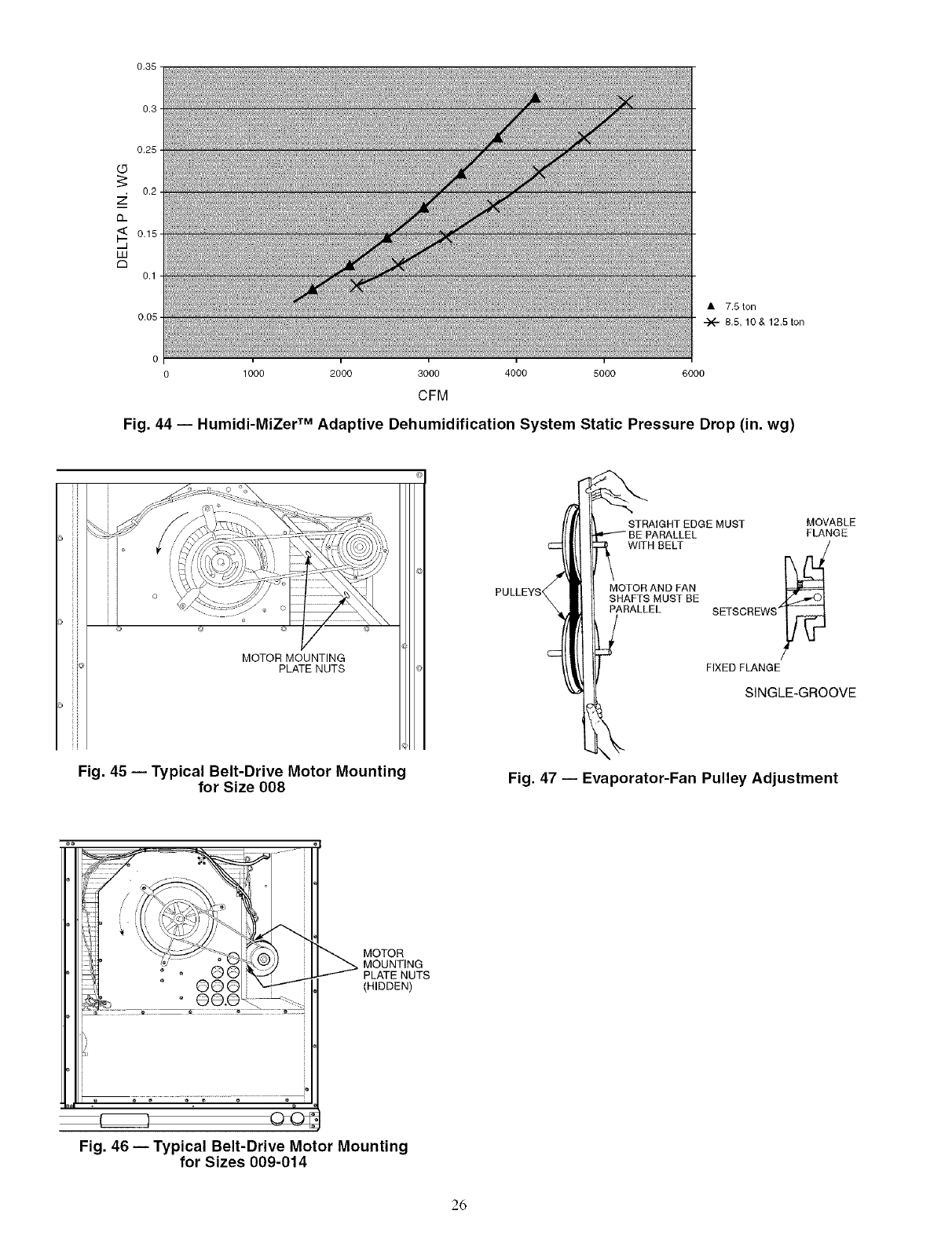
0.35
0.3
0.25 -
(_5
0.2
7;
Q-
0.15
IJJ
C3
0.1
0,05
• 7.5 ton
"-X" 8,5, 10 & 12,5 ton
0 _1 _ ;_ "i
0 1000 2000 3000 4000 5000
CFM
6000
Fig. 44 -- Humidi-MiZer TM Adaptive Dehumidification System Static Pressure Drop (in. wg)
MOTOR MOUNTING
PLATE NUTS
Fig. 45 -- Typical Belt-Drive Motor Mounting
for Size 008
_::_ ST%AIGHT EDGE MUST MOVABLE
PULLEYS MOTOR AND FAN _=====L_
SHAHS MUS[ BE _/_.._1
:3_ARALLEL SETSCREWS'_
FIXED FLANGE
i
I _ SINGLE-GROOVE
Fig. 47 -- Evaporator-Fan Pulley Adjustment
MOTOR
MOUNTING
PLATE NUTS
(HIDDEN)
Fig. 46 -- Typical Belt-Drive Motor Mounting
for Sizes 009-014
26
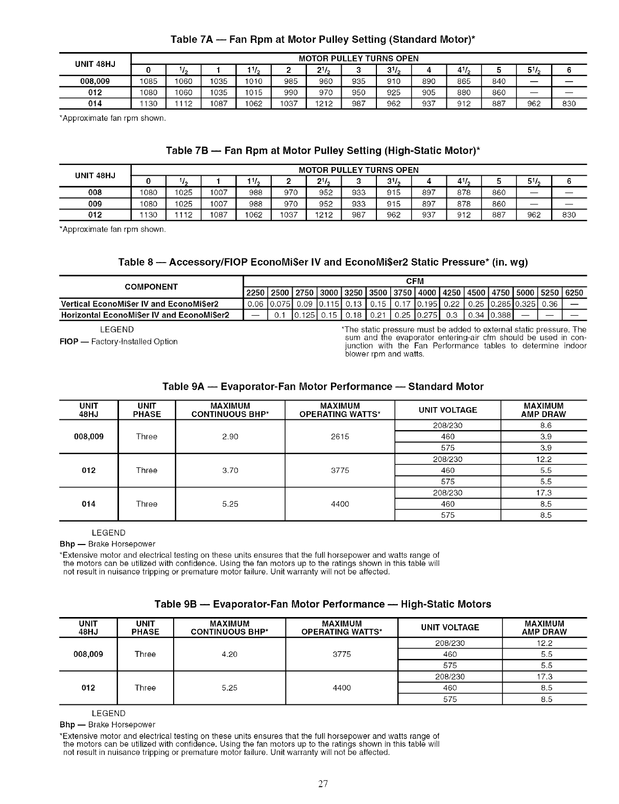
UNIT 48HJ 0
008,009 1085
012 1080
014 1130
*Approximatefan rpm shown.
Table 7A -- Fan Rpm at Motor Pulley Setting (Standard Motor)*
MOTOR PULLEY TURNS OPEN
1_ 1 11_ 2 21_ 3 31_ 441_ 5 51_ 6
1060 1035 1010 985 960 935 910 890 865 840 -- --
1060 1035 1015 990 970 950 925 905 880 860 -- --
1112 1087 1062 1037 1212 987 962 937 912 887 962 830
UNIT 48HJ 0
008 1080
009 1080
012 1130
*Approximatefan rpm shown.
Table 7B -- Fan Rpm at Motor Pulley Se_ing (High-Static Motor)*
MOTOR PULLEY TURNS OPEN
1_ 1 11_ 2 21_ 3 31_ 441_ 5 51_ 6
1025 1007 988 970 952 933 915 897 878 860 -- --
1025 1007 988 970 952 933 915 897 878 860 -- --
1112 1087 1062 1037 1212 987 962 937 912 887 962 830
Table 8 -- Accessory/FlOP EconoMi$er IV and EconoMi$er2 Static Pressure* (in. wg)
COMPONENT
Vertical EconoMi$er IV and EconoMi$er2
Horizontal EconoMi$er IV and EconoMi$er2
LEGEND
FlOP -- Factory-Installed Option
6250__
*The static pressure must be added to external static pressure. The
sum and the evaporator entering-air cfm should be used in con-
junction with the Fan Performance tables to determine indoor
blower rpm and watts.
Table 9A -- Evaporator-Fan Motor Performance -- Standard Motor
UNIT UNIT MAXIMUM MAXIMUM
48HJ PHASE CONTINUOUS BHP* OPERATING WATTS*
008,009
012
Three
Three
Three
2.90
3.70
5.25
2615
3775
440O
014
UNIT VOLTAGE
208/230
48O
575
208/230
48O
575
208/230
48O
575
MAXIMUM
AMP DRAW
8.6
3.9
3.9
12.2
5.5
5.5
17.3
8.5
8.5
LEGEND
Bhp -- Brake Horsepower
*Extensive motor and electrical testing on these units ensures that the full horsepower and watts range of
the motors can be utilized with confidence, Using the fan motors up to the ratings shown in this table will
not result in nuisance tripping or premature motor failure. Unit warranty will not be affected.
Table 9B -- Evaporator-Fan Motor Performance -- High-Static Motors
UNIT UNIT
48HJ PHASE
008,009 Three
012 Three
MAXIMUM
CONTINUOUS BHP*
4.20
5.25
MAXIMUM
OPERATING WATTS*
3775
44OO
LEGEND
Bhp -- Brake Horsepower
UNIT VOLTAGE
208/230
46O
575
208/230
46O
575
MAXIMUM
AMP DRAW
12.2
5.5
5.5
17.3
8.5
8.5
*Extensive motor and electrical testing on these units ensures that the full horsepower and watts range of
the motors can be utilized with confidence. Using the fan motors up to the ratings shown in this table will
not result in nuisance tripping or premature motor failure. Unit warranty will not be affected.
27
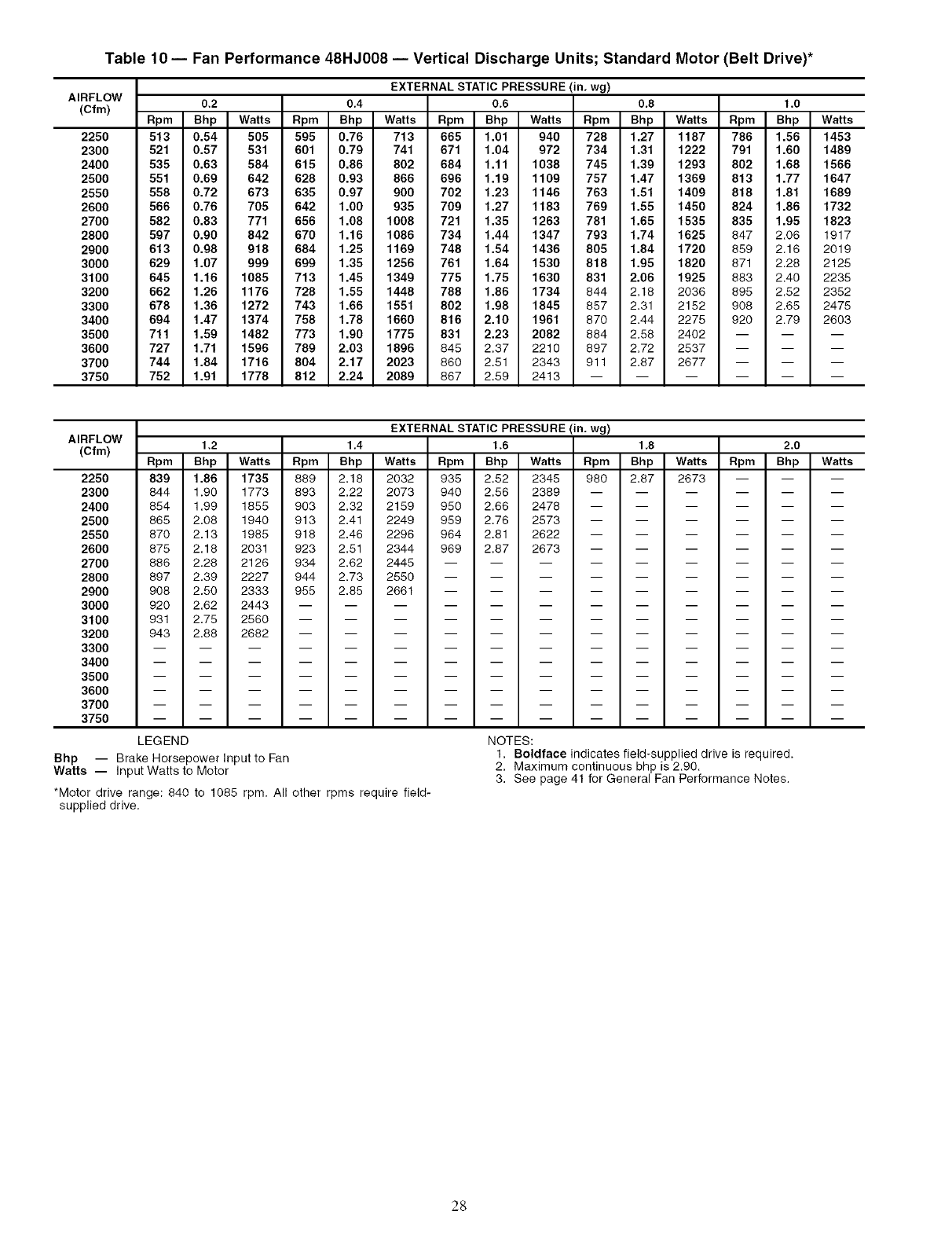
Table 10 -- Fan Performance 48HJ008 -- Vertical Discharge Units; Standard Motor (Belt Drive)*
AIRFLOW
(Cfm)
2250
2300
2400
2500
2550
2600
2700
2800
2900
3000
3100
3200
3300
3400
3500
3600
3700
3750
EXTERNAL STATIC PRESSURE (in. wg)
0.2 0.4 0.6 0.8 1.0
Rpm Bhp Watts Rpm Bhp Watts Rpm Bhp Watts Rpm Bhp Watts Rpm Bhp Watts
513 0.54 505 595 0.76 713 665 1.01 940 728 1.27 1187 786 1.56 1453
521 0.57 531 601 0.79 741 671 1.04 972 734 1.31 1222 791 1.60 1489
535 0.63 584 615 0.86 802 684 1.11 1038 745 1.39 1293 802 1.68 1566
551 0.69 642 628 0.93 866 696 1.19 1109 757 1.47 1369 813 1.77 1647
558 0.72 673 635 0.97 900 702 1.23 1146 763 1.51 1409 818 1.81 1689
566 0.76 705 642 1.00 935 709 1.27 1183 769 1.55 1450 824 1.86 1732
582 0.83 771 656 1.08 1008 721 1.35 1263 781 1.65 1535 835 1.95 1823
597 0.90 842 670 1.16 1086 734 1.44 1347 793 1.74 1625 847 2.06 1917
613 0.98 918 684 1.25 1169 748 1.54 1436 805 1.84 1720 859 2.16 2019
629 1.07 999 699 1.35 1256 761 1.64 1530 818 1.95 1820 871 2.28 2125
645 1.16 1085 713 1.45 1349 775 1.75 1630 831 2.06 1925 883 2.40 2235
662 1.26 1176 728 1.55 1448 788 1.86 1734 844 2.18 2036 895 2.52 2352
678 1.36 1272 743 1.66 1551 802 1.98 1845 857 2.31 2152 908 2.65 2475
694 1.47 1374 758 1.78 1660 816 2.10 1961 870 2.44 2275 920 2.79 2603
711 1.59 1482 773 1.90 1775 831 2.23 2082 884 2.58 2402 -- -- --
727 1.71 1596 789 2.03 1896 845 2.37 2210 897 2.72 2537 -- -- --
744 1.84 1716 804 2.17 2023 860 2.51 2343 911 2.87 2677 -- -- --
752 1.91 1778 812 2.24 2089 867 2.59 2413 ......
AIRFLOW
(Cfm) Rpm
2250 839
2300 844
2400 854
2500 865
2550 870
2600 875
2700 886
2800 897
2900 908 2.50
3000 920 2.62
3100 931 2.75
3200 943 2.88
3300 -- --
3400 -- --
3500 -- --
3600 -- --
3700 -- --
3750 -- --
LEGEND
Bhp --
Watts --
EXTERNAL STATIC PRESSURE (in. wg)
1.2 1.4 1.6 1.8 2.0
Bhp Watts Rpm Bhp Watts Rpm Bhp Watts Rpm Bhp Watts Rpm Bhp Watts
1.86 1735 889 2.18 2032 935 2.52 2345 980 2.87 2673 -- -- --
1.90 1773 893 2.22 2073 940 2.56 2389 ......
1.99 1855 903 2.32 2159 950 2.66 2478 ......
2.08 1940 913 2.41 2249 959 2.76 2573 ......
2.13 1985 918 2.46 2296 964 2.81 2622 ......
2.18 2031 923 2.51 2344 969 2.87 2673 ......
2.28 2126 934 2.62 2445 .........
2.39 2227 944 2.73 2550 .........
2333 955 2.85 2661 .........
2443 ............
2560 ............
2682 ............
Brake Horsepower Input to Fan
Input Watts to Motor
NOTES:
1. Boldface indicates field-supplied drive is required.
2. Maximum continuous bhp is 2.90.
3. See page 41 for General Fan Performance Notes.
*Motor drive range: 840 to 1085 rpm. All other rpms require field-
supplied drive.
28
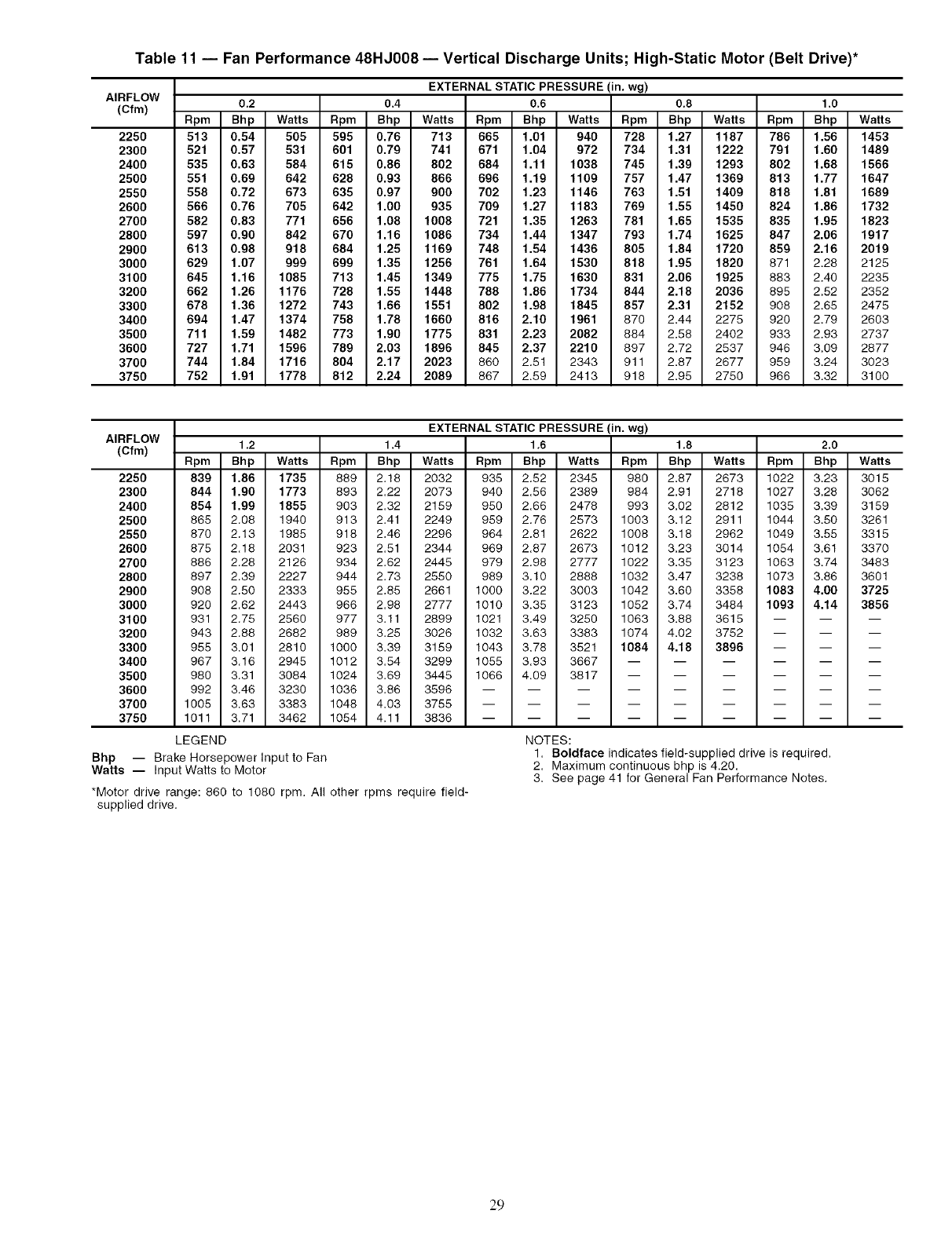
Table 11 -- Fan Performance 48HJ008 -- Vertical Discharge Units; High-Static Motor (Belt Drive)*
AIRFLOW
(Cfm)
2250
2300
2400
2500
2550
2600
2700
2800
2900
3000
3100
3200
3300
3400
3500
3600
3700
3750
EXTERNAL STATIC PRESSURE (in. wg)
0.2 0.4 0.6 0.8 1.0
Rpm Bhp Watts Rpm Bhp Watts Rpm Bhp Watts Rpm Bhp Watts Rpm Bhp Watts
513 0.54 505 595 0.76 713 665 1.01 940 728 1.27 1187 786 1.56 1453
521 0.57 531 601 0.79 741 671 1.04 972 734 1.31 1222 791 1.60 1489
535 0.63 584 615 0.86 802 684 1.11 1038 745 1.39 1293 802 1.68 1566
551 0.69 642 628 0.93 866 696 1.19 1109 757 1.47 1369 813 1.77 1647
558 0.72 673 635 0.97 900 702 1.23 1146 763 1.51 1409 818 1.81 1689
566 0.76 705 642 1.00 935 709 1.27 1183 769 1.55 1450 824 1.86 1732
582 0.83 771 656 1.08 1008 721 1.35 1263 781 1.65 1535 835 1.95 1823
597 0.90 842 670 1.16 1086 734 1.44 1347 793 1.74 1625 847 2.06 1917
613 0.98 918 684 1.25 1169 748 1.54 1436 805 1.84 1720 859 2.16 2019
629 1.07 999 699 1.35 1256 761 1.64 1530 818 1.95 1820 871 2.28 2125
645 1.16 1085 713 1.45 1349 775 1.75 1630 831 2.06 1925 883 2.40 2235
662 1.26 1176 728 1.55 1448 788 1.86 1734 844 2.18 2036 695 2.52 2352
678 1.36 1272 743 1.66 1551 802 1.98 1845 857 2.31 2152 908 2.65 2475
694 1.47 1374 758 1.78 1660 816 2.10 1961 870 2.44 2275 920 2.79 2603
711 1.59 1482 773 1.90 1775 831 2.23 2082 884 2.58 2402 933 2.93 2737
727 1.71 1596 789 2.03 1896 845 2.37 2210 897 2.72 2537 946 3.09 2877
744 1.84 1716 804 2.17 2023 880 2.51 2343 911 2.87 2677 959 3.24 3023
752 1.91 1778 812 2.24 2089 867 2.59 2413 918 2.95 2750 966 3.32 3100
AIRFLOW
(Cfm) Rpm
2250 839
2300 844
2400 854
2500 865
2550 870
2600 875
2700 886
2800 897
2900 908 2.50
3000 920 2.62
3100 931 2.75
3200 943 2.88
3300 955 3.01
3400 967 3.16
3500 980 3.31
3600 992 3.46
3700 1005 3.63
3750 1011 3.71
LEGEND
EXTERNAL STATIC PRESSURE(in. wg)
1.2 1.4 1,6 1,8 2,0
Bhp Watts Rpm Bhp Watts Rpm Bhp Watts Rpm Bhp Watts Rpm Bhp Watts
1.86 1735 889 2.18 2032 935 2.52 2345 980 2.87 2673 1022 3.23 3015
1.90 1773 893 2.22 2073 940 2.58 2389 984 2.91 2718 1027 3.28 3062
1.99 1855 903 2.32 2159 950 2.68 2478 993 3.02 2812 1035 3.39 3159
2.08 1940 913 2.41 2249 959 2.78 2573 1003 3.12 2911 1044 3.50 3261
2.13 1985 918 2.46 2298 964 2.81 2622 1008 3.18 2962 1049 3.55 3315
2.18 2031 923 2.51 2344 969 2.87 2673 1012 3.23 3014 1054 3.61 3370
2.28 2126 934 2.62 2445 979 2.98 2777 1022 3.35 3123 1063 3.74 3483
2.39 2227 944 2.73 2550 989 3.10 2888 1032 3.47 3238 1073 3.86 3601
2333 955 2.85 2661 1000 3.22 3003 1042 3.60 3358 1083 4.00 3725
2443 968 2.98 2777 1010 3.35 3123 1052 3.74 3484 1093 4.14 3856
2560 977 3.11 2899 1021 3.49 3250 1063 3.88 3615 -- -- --
2682 989 3.25 3026 1032 3.63 3383 1074 4.02 3752 -- -- --
2810 1000 3.39 3159 1043 3.78 3521 1084 4.18 3896 -- -- --
2945 1012 3.54 3299 1055 3.93 3667 ......
3084 1024 3.69 3445 1066 4.09 3817 ......
3230 1036 3.86 3596 .........
3383 1048 4.03 3755 .........
3462 1054 4.11 3836 .........
Bhp -- Brake Horsepower Input to Fan
Watts -- Input Watts to Motor
NOTES:
1. Boldface indicates field-supplied drive is required.
2. Maximum continuous bhp is 4.20.
3. See page 41 for General Fan Performance Notes.
*Motor drive range: 860 to 1080 rpm. All other rpms require field-
supplied drive.
29

Table 12 -- Fan Performance 48HJ009 -- Vertical Discharge Units; Standard Motor (Belt Drive)*
AIRFLOW
(Cfm)
2500
2600
2700
2800
2900
3000
3100
3200
3300
3400
3500
3600
3700
3800
3900
4000
4100
4200
4300
EXTERNAL STATIC PRESSURE (in. wg)
0.2 0.4 0.6 0.8 1.0
Rpm Bhp Watts Rpm Bhp Watts Rpm Bhp Watts Rpm Bhp Watts Rpm Bhp Watts
541 0.50 467 624 0.66 614 701 0.83 771 771 1.00 936 837 1.19 1109
556 0.55 513 637 0.71 665 711 0.89 827 781 1.07 996 845 1.26 1173
571 0.60 562 650 0.77 720 722 0.95 885 790 1.14 1059 854 1.33 1241
586 0.66 615 663 0.83 777 734 1.02 948 800 1.21 1126 863 1.41 1312
601 0.72 672 676 0.90 839 745 1.09 1014 811 1.28 1197 872 1.49 1387
616 0.79 732 689 0.97 904 757 1.16 1083 821 1.36 1271 882 1.57 1465
632 0.85 796 703 1.04 972 769 1.24 1157 832 1.45 1349 892 1.66 1548
648 0.93 864 717 1.12 1045 782 1.32 1235 843 1.53 1431 902 1.75 1635
663 1.00 936 731 1.20 1122 795 1.41 1316 855 1.63 1517 912 1.85 1725
679 1.09 1012 745 1.29 1203 808 1.50 1402 867 1.72 1608 923 1.95 1820
695 1.17 1092 760 1.38 1288 821 1.60 1492 879 1.83 1703 934 2.06 1920
711 1.26 1177 774 1.48 1379 834 1.70 1587 891 1.93 1802 945 2.17 2024
728 1.36 1266 789 1.58 1473 848 1.81 1686 904 2.04 1908 957 2.29 2132
744 1.46 1361 804 1.69 1572 861 1.92 1790 918 2.16 2015 969 2.41 2246
760 1.57 1460 819 1.80 1676 875 2.04 1899 929 2.28 2128 981 2.53 2364
777 1.68 1563 834 1.91 1785 889 2.16 2012 942 2.41 2247 993 2.67 2487
793 1.79 1672 850 2.04 1899 904 2.29 2132 956 2.54 2371 1006 2.80 2615
810 1.92 1786 865 2.16 2018 918 2.42 2255 969 2.68 2499 -- -- --
826 2.04 1906 880 2.30 2142 932 2.56 2385 983 2.82 2633 -- -- --
AIRFLOW
(Cfm)
2500
2600
2700
2800
2900
3000
3100
3200
3300
3400
3500
3600
3700
3800
3900
4000
4100
4200
4300
EXTERNAL STATIC PRESSURE (in. wg)
1.2 1.4 1.6 1.8 2.0
Rpm Bhp Watts Rpm Bhp Watts Rpm Bhp Watts Rpm Bhp Watts Rpm Bhp Watts
900 1.38 1289 959 1.58 1476 1015 1.79 1669 1069 2.00 1868 1121 2.22 2073
907 1.46 1357 965 1.66 1548 1021 1.87 1745 1074 2.09 1948 1125 2.31 2158
914 1.53 1429 972 1.74 1824 1027 1.96 1825 1079 2.18 2032 1130 2.41 2245
922 1.61 1505 979 1.83 1704 1033 2.05 1909 1085 2.27 2120 1135 2.51 2337
931 1.70 1584 986 1.92 1787 1040 2.14 1996 1091 2.37 2211 1141 2.61 2432
939 1.79 1667 994 2.01 1874 1047 2.24 2087 1098 2.47 2307 1147 2.71 2532
948 1.88 1753 1002 2.11 1965 1054 2.34 2183 1105 2.58 2406 1153 2.83 2635
957 1.98 1844 1011 2.21 2060 1062 2.45 2283 1112 2.69 2510 -- -- --
967 2.08 1939 1020 2.32 2160 1070 2.56 2386 1119 2.81 2618 -- -- --
977 2.19 2039 1029 2.43 2264 1079 2.67 2494 ......
987 2.30 2143 1038 2.54 2372 1088 2.80 2607 ......
998 2.41 2251 1048 2.66 2485 .........
1008 2.54 2364 1058 2.79 2602 .........
1019 2.66 2482 ............
1031 2.79 2605 ............
LEGEND
Bhp -- Brake Horsepower Input to Fan
Watts -- Input Watts to Motor
*Motor drive range: 840 to 1085 rpm. All other rpms require field-
supplied drive.
NOTES:
1. Boldface indicates field-supplied drive is required.
2. Maximum continuous bhp is 2.90.
3. See page 41 for General Fan Performance Notes.
3O
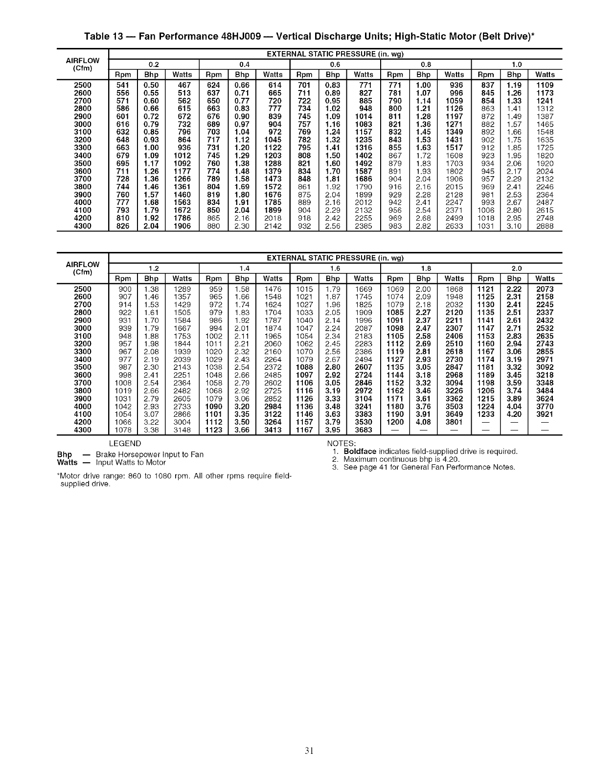
Table 13 -- Fan Performance 48HJ009 -- Vertical Discharge Units; High-Static Motor (Belt Drive)*
AIRFLOW
(Cfm)
2500
2600
2700
2800
2900
3000
3100
3200
3300
3400
3500
3600
3700
3800
3900
4000
4100
4200
4300
EXTERNAL STATIC PRESSURE (in. wg)
0.2 0.4 0.6 0.8 1.0
Rpm Bhp Watts Rpm Bhp Watts Rpm Bhp Watts Rpm Bhp Watts Rpm Bhp Watts
541 0.50 467 624 0.66 614 701 0.83 771 771 1.00 936 837 1.19 1109
556 0.55 513 637 0.71 665 711 0.89 827 781 1.07 996 845 1.26 1173
571 0.60 562 650 0.77 720 722 0.95 885 790 1.14 1059 854 1.33 1241
586 0.66 615 663 0.83 777 734 1.02 948 800 1.21 1126 863 1.41 1312
601 0.72 672 676 0.90 839 745 1.09 1014 811 1.28 1197 872 1.49 1387
616 0.79 732 689 0.97 904 757 1.16 1083 821 1.36 1271 882 1.57 1465
632 0.85 796 703 1.04 972 769 1.24 1157 832 1.45 1349 892 1.66 1548
648 0.93 864 717 1.12 1045 782 1.32 1235 843 1.53 1431 902 1.75 1635
663 1.00 936 731 1.20 1122 795 1.41 1316 855 1.63 1517 912 1.85 1725
679 1.09 1012 745 1.29 1203 808 1.50 1402 867 1.72 1608 923 1.95 1820
695 1.17 1092 760 1.38 1288 821 1.60 1492 879 1.83 1703 934 2.06 1920
711 1.26 1177 774 1.48 1379 834 1.70 1587 891 1.93 1802 945 2.17 2024
728 1.36 1266 789 1.58 1473 848 1.81 1686 904 2.04 1906 957 2.29 2132
744 1.46 1361 804 1.69 1572 861 1.92 1790 916 2.16 2015 969 2.41 2246
760 1.57 1460 819 1.80 1676 875 2.04 1899 929 2.28 2128 981 2.53 2364
777 1.68 1563 834 1.91 1785 889 2.16 2012 942 2.41 2247 993 2.67 2487
793 1.79 1672 850 2.04 1899 904 2.29 2132 956 2.54 2371 1006 2.80 2615
810 1.92 1786 865 2.16 2018 918 2.42 2255 969 2.68 2499 1018 2.95 2748
826 2.04 1906 880 2.30 2142 932 2.56 2385 983 2.82 2633 1031 3.10 2888
AIRFLOW
(Cfm)
2500
2600
2700
2800
2900
3000
3100
3200
3300
3400
3500
3600
3700
3800
3900
4000
4100
4200
4300
Bhp -- Brake Horsepower Input to Fan
Watts -- Input Watts to Motor
*Motor drive range: 860 to 1080 rpm. All other rpms require field-
supplied drive.
EXTERNAL STATIC PRESSURE (in. wg)
1.2 1,4 1,6 1,8 2,0
Rpm Bhp Watts Rpm Bhp Watts Rpm Bhp Watts Rpm Bhp Watts Rpm Bhp Watts
900 1.38 1289 959 1.58 1476 1015 1.79 1669 1069 2.00 1868 1121 2.22 2073
907 1.46 1357 965 1.66 1548 1021 1.87 1745 1074 2.09 1948 1125 2.31 2158
914 1.53 1429 972 1.74 1624 1027 1.96 1825 1079 2.18 2032 1130 2.41 2245
922 1.61 1505 979 1.83 1704 1033 2.05 1909 1085 2.27 2120 1135 2.51 2337
931 1.70 1584 986 1.92 1787 1040 2.14 1996 1091 2.37 2211 1141 2.61 2432
939 1.79 1667 994 2.01 1874 1047 2.24 2087 1098 2.47 2307 1147 2.71 2532
948 1.88 1753 1002 2.11 1965 1054 2.34 2183 1105 2.58 2406 1153 2.83 2635
957 1.98 1844 1011 2.21 2060 1062 2.45 2283 1112 2.69 2510 1160 2.94 2743
967 2.08 1939 1020 2.32 2160 1070 2.56 2386 1119 2.81 2618 1167 3.06 2855
977 2.19 2039 1029 2.43 2264 1079 2.67 2494 1127 2.93 2730 1174 3.19 2971
987 2.30 2143 1038 2.54 2372 1088 2.80 2607 1135 3.05 2847 1181 3.32 3092
998 2.41 2251 1048 2.66 2485 1097 2.92 2724 1144 3.18 2968 1189 3.45 3218
1008 2.54 2364 1058 2.79 2602 1106 3.05 2846 1152 3.32 3094 1198 3.59 3348
1019 2.66 2482 1068 2.92 2725 1116 3.19 2972 1162 3.46 3226 1206 3.74 3484
1031 2.79 2605 1079 3.06 2852 1126 3.33 3104 1171 3.61 3362 1215 3.89 3624
1042 2.93 2733 1090 3.20 2984 1136 3.48 3241 1180 3.76 3503 1224 4.04 3770
1054 3.07 2866 1101 3.35 3122 1146 3.63 3383 1190 3.91 3649 1233 4.20 3921
1066 3.22 3004 1112 3.50 3264 1157 3.79 3530 1200 4.08 3801 -- -- --
1078 3.38 3148 1123 3.66 3413 1167 3.95 3683 ......
LEGEND NOTES:
1. Boldface indicates field-supplied drive is required.
2. Maximum continuous bhp is 4.20.
3. See page 41 for General Fan Performance Notes.
3!
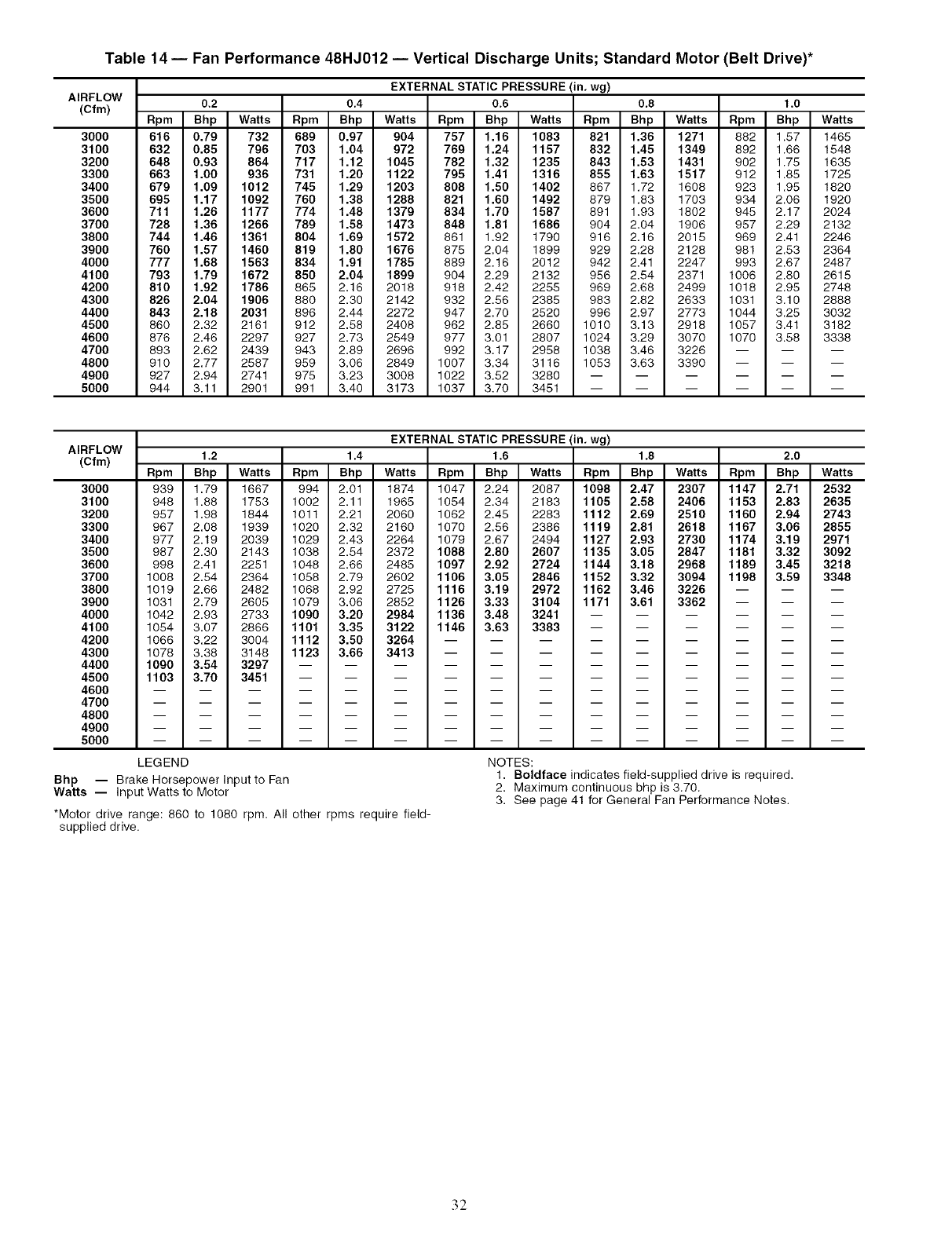
Table 14 -- Fan Performance 48HJ012 -- Vertical Discharge Units; Standard Motor (Belt Drive)*
AIRFLOW
(Cfm)
3O00
3100
3200
3300
3400
3500
3600
3700
3800
3900
4000
4100
4200
4300
4400
4500
4600
4700
4800
4900
5000
EXTERNAL STATIC PRESSURE (in. wg)
0.2 0.4 0.6 0.8 1.0
Rpm Bhp Watts Rpm Bhp Watts Rpm Bhp Watts Rpm Bhp Watts Rpm Bhp Watts
616 0.79 732 689 0.97 904 757 1.16 1083 821 1.36 1271 882 1.57 1465
632 0.85 796 703 1.04 972 769 1.24 1157 832 1.45 1349 892 1.66 1548
648 0.93 864 717 1.12 1045 782 1.32 1235 843 1.53 1431 902 1.75 1635
663 1.00 936 731 1.20 1122 795 1.41 1316 855 1.63 1517 912 1.85 1725
679 1.09 1012 745 1.29 1203 808 1.50 1402 867 1.72 1608 923 1.95 1820
695 1.17 1092 760 1.38 1288 821 1.60 1492 879 1.83 1703 934 2.06 1920
711 1.26 1177 774 1.48 1379 834 1.70 1587 891 1.93 1802 945 2.17 2024
728 1.36 1266 789 1.58 1473 848 1.81 1686 904 2.04 1908 957 2.29 2132
744 1.46 1361 804 1.69 1572 861 1.92 1790 918 2.16 2015 989 2.41 2246
760 1.57 1460 819 1.80 1676 875 2.04 1899 929 2.28 2128 981 2.53 2364
777 1.68 1563 834 1.91 1785 889 2.16 2012 942 2.41 2247 993 2.67 2487
793 1.79 1672 850 2.04 1899 904 2.29 2132 956 2.54 2371 1006 2.80 2615
810 1.92 1786 865 2.16 2018 918 2.42 2255 969 2.68 2499 1018 2.95 2748
826 2.04 1906 880 2.30 2142 932 2.56 2385 983 2.82 2633 1031 3.10 2888
843 2.18 2031 898 2.44 2272 947 2.70 2520 998 2.97 2773 1044 3.25 3032
860 2.32 2161 912 2.58 2408 982 2.85 2660 1010 3.13 2918 1057 3.41 3182
878 2.46 2297 927 2.73 2549 977 3.01 2807 1024 3.29 3070 1070 3.58 3338
893 2.62 2439 943 2.89 2696 992 3.17 2958 1038 3.46 3226 -- -- --
910 2.77 2587 959 3.06 2849 1007 3.34 3116 1053 3.63 3390 -- -- --
927 2.94 2741 975 3,23 3008 1022 3,52 3280 ......
944 3.11 2901 991 3.40 3173 1037 3.70 3451 ......
AIRFLOW
(Cfm)
3000
3100
3200
3300
3400
3500
3600
3700
3800
3900
4000
4100
4200
4300
4400
4500
4600
4700
4800
4900
5000
EXTERNAL STATIC PRESSURE (in. wg)
1.2 1.4 1.6 1.8 2.0
Rpm Bhp Watts Rpm Bhp Watts Rpm Bhp Watts Rpm Bhp Watts Rpm Bhp Watts
939 1.79 1667 994 2.01 1874 1047 2.24 2087 1098 2.47 2307 1147 2.71 2532
948 1.88 1753 1002 2.11 1965 1054 2.34 2183 1105 2.58 2406 1153 2.83 2635
957 1.98 1844 1011 2.21 2060 1062 2.45 2283 1112 2.69 2510 1160 2.94 2743
967 2.08 1939 1020 2.32 2160 1070 2.56 2386 1119 2.81 2618 1167 3.06 2855
977 2.19 2039 1029 2.43 2264 1079 2.87 2494 1127 2.93 2730 1174 3.19 2971
987 2.30 2143 1038 2.54 2372 1088 2.80 2607 1135 3.05 2847 1181 3.32 3092
998 2.41 2251 1048 2.66 2485 1097 2.92 2724 1144 3.18 2968 1189 3.45 3218
1008 2.54 2364 1058 2.79 2602 1106 3.05 2846 1152 3.32 3094 1198 3.59 3348
1019 2.66 2482 1068 2.92 2725 1116 3.19 2972 1162 3.46 3226 -- -- --
1031 2.79 2605 1079 3.06 2852 1126 3.33 3104 1171 3.61 3362 -- -- --
1042 2.93 2733 1090 3.20 2984 1136 3.48 3241 ......
1054 3.07 2866 1101 3.35 3122 1146 3.63 3383 ......
1066 3.22 3004 1112 3.50 3264 .........
1078 3.38 3148 1123 3.66 3413 .........
1090 3.54 3297 ............
1103 3.70 3451 ............
LEGEND
Bhp -- Brake Horsepower Input to Fan
Watts -- Input Watts to Motor
*Motor drive range: 860 to 1080 rpm. All other rpms require field-
supplied drive.
NOTES:
1. Boldface indicates field-supplied drive is required.
2. Maximum continuous bhp is 3.70.
3. See page 41 for General Fan Performance Notes.
32
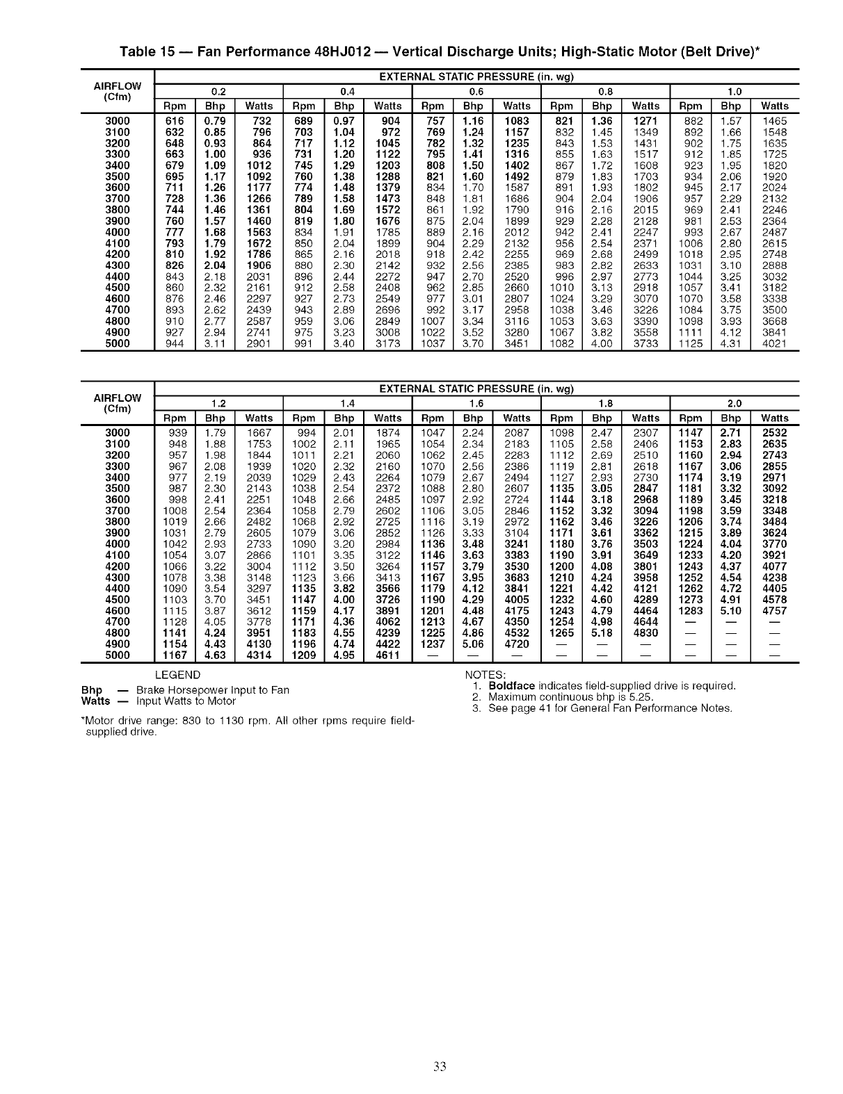
Table 15 -- Fan Performance 48HJ012 -- Vertical Discharge Units; High-Static Motor (Belt Drive)*
AIRFLOW
(Cfm)
3O0O
3100
3200
3300
3400
3500
3600
3700
3800
3900
4000
4100
4200
4300
4400
4500
4600
4700
4800
4900
5000
EXTERNAL STATIC PRESSURE (in. wg)
0.2 0.4 0.6 0.8 1.0
Rpm Bhp Watts Rpm Bhp Watts Rpm Bhp Watts Rpm Bhp Watts Rpm Bhp Watts
616 0.79 732 689 0.97 904 757 1.16 1083 821 1.36 1271 882 1.57 1465
632 0.85 796 703 1.04 972 769 1.24 1157 832 1.45 1349 892 1.66 1548
648 0.93 864 717 1.12 1045 782 1.32 1235 843 1.53 1431 902 1.75 1635
663 1.00 936 731 1.20 1122 795 1.41 1316 855 1.63 1517 912 1.85 1725
679 1.09 1012 745 1.29 1203 808 1.50 1402 867 1.72 1608 923 1.95 1820
695 1.17 1092 760 1.38 1288 821 1.60 1492 879 1.83 1703 934 2.06 1920
711 1.26 1177 774 1.48 1379 834 1.70 1587 891 1.93 1802 945 2.17 2024
728 1.36 1266 789 1.58 1473 848 1.81 1686 904 2.04 1906 957 2.29 2132
744 1.46 1361 804 1.69 1572 861 1.92 1790 916 2.16 2015 969 2.41 2246
760 1.57 1460 819 1.80 1676 875 2.04 1899 929 2.28 2128 981 2.53 2364
777 1.68 1563 834 1.91 1785 889 2.16 2012 942 2.41 2247 993 2.67 2487
793 1.79 1672 850 2.04 1899 904 2.29 2132 956 2.54 2371 1006 2.80 2615
810 1.92 1786 865 2.16 2018 918 2.42 2255 969 2.68 2499 1018 2.95 2748
826 2.04 1906 880 2.30 2142 932 2.56 2385 983 2.82 2633 1031 3.10 2888
843 2.18 2031 896 2.44 2272 947 2.70 2520 996 2.97 2773 1044 3.25 3032
860 2.32 2161 912 2.58 2408 962 2.85 2660 1010 3.13 2918 1057 3.41 3182
876 2.46 2297 927 2.73 2549 977 3.01 2807 1024 3.29 3070 1070 3.58 3338
893 2.62 2439 943 2.89 2696 992 3.17 2958 1038 3.46 3226 1084 3.75 3500
910 2.77 2587 959 3.06 2849 1007 3.34 3116 1053 3.63 3390 1098 3.93 3668
927 2.94 2741 975 3.23 3008 1022 3.52 3280 1067 3.82 3558 1111 4.12 3841
944 3.11 2901 991 3.40 3173 1037 3.70 3451 1082 4.00 3733 1125 4.31 4021
AIRFLOW
(Cfm)
300O
3100
3200
3300
3400
3500
3600
3700
3800
3900
4000
4100
4200
4300
4400
4500
4600
4700
4800
4900
5000
Bhp -- Brake Horsepower Input to Fan
Watts -- Input Watts to Motor
EXTERNAL STATIC PRESSURE (in. wg)
1.2 1.4 1.6 1.8 2,0
Rpm Bhp Watts Rpm Bhp Watts Rpm Bhp Watts Rpm Bhp Watts Rpm Bhp Watts
939 1.79 1667 994 2.01 1874 1047 2.24 2087 1098 2.47 2307 1147 2.71 2532
948 1.88 1753 1002 2.11 1965 1054 2.34 2183 1105 2.58 2406 1153 2.83 2635
957 1.98 1844 1011 2.21 2060 1062 2.45 2283 1112 2.69 2510 1160 2.94 2743
967 2.08 1939 1020 2.32 2160 1070 2.56 2386 1119 2.81 2618 1167 3.06 2855
977 2.19 2039 1029 2.43 2264 1079 2.67 2494 1127 2.93 2730 1174 3.19 2971
987 2.30 2143 1038 2.54 2372 1088 2.80 2607 1135 3.05 2847 1181 3.32 3092
998 2.41 2251 1048 2.66 2485 1097 2.92 2724 1144 3.18 2968 1189 3.45 3218
1008 2.54 2364 1058 2.79 2602 1106 3.05 2846 1152 3.32 3094 1198 3.59 3348
1019 2.66 2482 1068 2.92 2725 1116 3.19 2972 1162 3.46 3226 1206 3.74 3484
1031 2.79 2605 1079 3.06 2852 1126 3.33 3104 1171 3.61 3362 1215 3.89 3624
1042 2.93 2733 1090 3.20 2984 1136 3.48 3241 1180 3.76 3503 1224 4.04 3770
1054 3.07 2866 1101 3.35 3122 1146 3.63 3383 1190 3.91 3649 1233 4.20 3921
1066 3.22 3004 1112 3.50 3264 1157 3.79 3530 1200 4.08 3801 1243 4.37 4077
1078 3.38 3148 1123 3.66 3413 1167 3.95 3683 1210 4.24 3958 1252 4.54 4238
1090 3.54 3297 1135 3.82 3566 1179 4.12 3841 1221 4.42 4121 1262 4.72 4405
1103 3.70 3451 1147 4.00 3726 1190 4.29 4005 1232 4.60 4289 1273 4.91 4578
1115 3.87 3612 1159 4.17 3891 1201 4.48 4175 1243 4.79 4464 1283 5.10 4757
1128 4.05 3778 1171 4.36 4062 1213 4.67 4350 1254 4.98 4644 -- -- --
1141 4.24 3951 1183 4.55 4239 1225 4.86 4532 1265 5.18 4830 -- -- --
1154 4.43 4130 1196 4.74 4422 1237 5.06 4720 ......
1167 4.63 4314 1209 4.95 4611 .........
LEGEND NOTES:
1. Boldface indicates field-supplied drive is required.
2. Maximum continuous bhp is 5.25.
3. See page 41 for General Fan Performance Notes.
*Motor drive range: 830 to 1130 rpm. All other rpms require field-
supplied drive.
.3.3
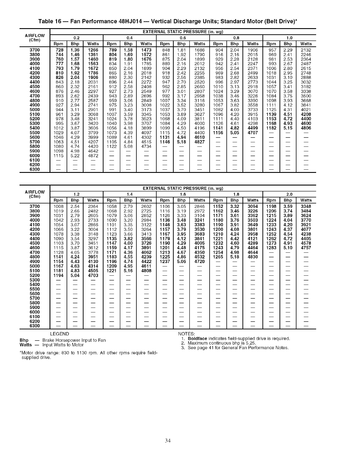
Table 16 -- Fan Performance 48HJ014 -- Vertical Discharge Units; Standard Motor (Belt Drive)*
AIRFLOW
(Cfm)
37OO
3800
3900
4000
4100
4200
4300
4400
4500
4600
4700
4800
4900
5000
5100
5200
5300
5400
5500
5600
5700
5800
5900
6000
6100
6200
6300
EXTERNAL STATIC PRESSURE (in. wg)
0.2 0.4 0.6 0.8 1.0
Rpm Bhp Watts Rpm Bhp Watts Rpm Bhp Watts Rpm Bhp Watts Rpm Bhp Watts
728 1.36 1266 789 1.58 1473 848 1.81 1686 904 2.04 1906 957 2.29 2132
744 1.46 1361 804 1.69 1572 861 1.92 1790 916 2.16 2015 969 2.41 2246
760 1.57 1460 819 1.80 1676 875 2.04 1899 929 2.28 2128 981 2.53 2364
777 1.68 1563 834 1.91 1785 889 2.16 2012 942 2.41 2247 993 2.67 2487
793 1.79 1672 850 2.04 1899 904 2.29 2132 956 2.54 2371 1006 2.80 2615
810 1.92 1786 865 2.16 2018 918 2.42 2255 969 2.68 2499 1018 2.95 2748
826 2.04 1906 880 2.30 2142 932 2.56 2385 983 2.82 2633 1031 3.10 2888
843 2.18 2031 896 2.44 2272 947 2.70 2520 996 2.97 2773 1044 3.25 3032
860 2.32 2161 912 2.58 2408 962 2.85 2660 1010 3.13 2918 1057 3.41 3182
876 2.46 2297 927 2.73 2549 977 3.01 2807 1024 3.29 3070 1070 3.58 3338
893 2.62 2439 943 2.89 2696 992 3.17 2958 1038 3.46 3226 1084 3.75 3500
910 2.77 2587 959 3.06 2849 1007 3.34 3116 1053 3.63 3390 1098 3.93 3668
927 2.94 2741 975 3.23 3008 1022 3.52 3280 1067 3.82 3558 1111 4.12 3841
944 3.11 2901 991 3.40 3173 1037 3.70 3451 1082 4.00 3733 1125 4.31 4021
961 3.29 3068 1007 3.59 3345 1053 3.89 3627 1096 4.20 3915 1139 4.51 4208
978 3.48 3241 1024 3.78 3523 1068 4.09 3811 1111 4.40 4103 1153 4.72 4400
995 3.67 3420 1040 3.98 3707 1084 4.29 4000 1126 4.61 4298 1168 4.93 4600
1012 3.87 3606 1056 4.18 3899 1099 4.50 4196 1141 4.82 4499 1182 5.15 4806
1029 4.07 3799 1073 4.39 4097 1115 4.72 4400 1156 5.05 4707 -- -- --
1046 4.29 3999 1089 4.61 4302 1131 4.94 4610 ......
1063 4.51 4207 1105 4.84 4515 1146 5.18 4827 ......
1080 4.74 4420 1122 5.08 4734 .........
1098 4.98 4642 ............
1115 5.22 4872 ............
AIRFLOW
(Cfm)
37O0
3800
3g00
4000
4100
4200
4300
4400
4500
4600
4700
4800
4900
5000
5100
5200
5300
5400
5500
5600
5700
5800
5900
6000
6100
6200
6300
EXTERNAL STATIC PRESSURE (in, wg)
1,2 1,4 1,6 1,8 2,0
Rpm Bhp Watts Rpm Bhp Watts Rpm Bhp Watts Rpm Bhp Watts Rpm Bhp Watts
1008 2.54 2364 1058 2.79 2602 1106 3.05 2846 1152 3.32 3094 1198 3.59 3348
1019 2.68 2482 1068 2.92 2725 1116 3.19 2972 1162 3.46 3226 1206 3.74 3484
1031 2.79 2605 1079 3.06 2852 1128 3.33 3104 1171 3.61 3362 1215 3.89 3624
1042 2.93 2733 1090 3.20 2984 1136 3.48 3241 1180 3.76 3503 1224 4.04 3770
1054 3.07 2868 1101 3.35 3122 1146 3.63 3383 1190 3.91 3649 1233 4.20 3921
1068 3.22 3004 1112 3.50 3264 1157 3.79 3530 1200 4.08 3801 1243 4.37 4077
1078 3.38 3148 1123 3.66 3413 1167 3.95 3683 1210 4.24 3958 1252 4.54 4238
1090 3.54 3297 1135 3.82 3566 1179 4.12 3841 1221 4.42 4121 1262 4.72 4405
1103 3.70 3451 1147 4.00 3726 1190 4.29 4005 1232 4.60 4289 1273 4.91 4578
1115 3.87 3612 1159 4.17 3891 1201 4.48 4175 1243 4.79 4464 1283 5.10 4757
1128 4.05 3778 1171 4.36 4062 1213 4.67 4350 1254 4.98 4644 -- --
1141 4.24 3951 1183 4.55 4239 1225 4.86 4532 1265 5.18 4830 -- --
1154 4.43 4130 1196 4.74 4422 1237 5.06 4720 -- --
1167 4.63 4314 1209 4.95 4611 -- --
1181 4.83 4505 1221 5.16 4808 -- --
1194 5.04 4703 --
m
m
m
m
m
m
m
m
m
m
m
LEGEND
Bhp -- Brake Horsepower Input to Fan
Watts -- Input Watts to Motor
*Motor drive range: 630 to 1130 rpm. All other rpms require field-
supplied drive.
NOTES:
1. Boldface indicates field-supplied drive is required.
2. Maximum continuous bhp is 5.25.
3. See page 41 for General Fan Performance Notes.
34
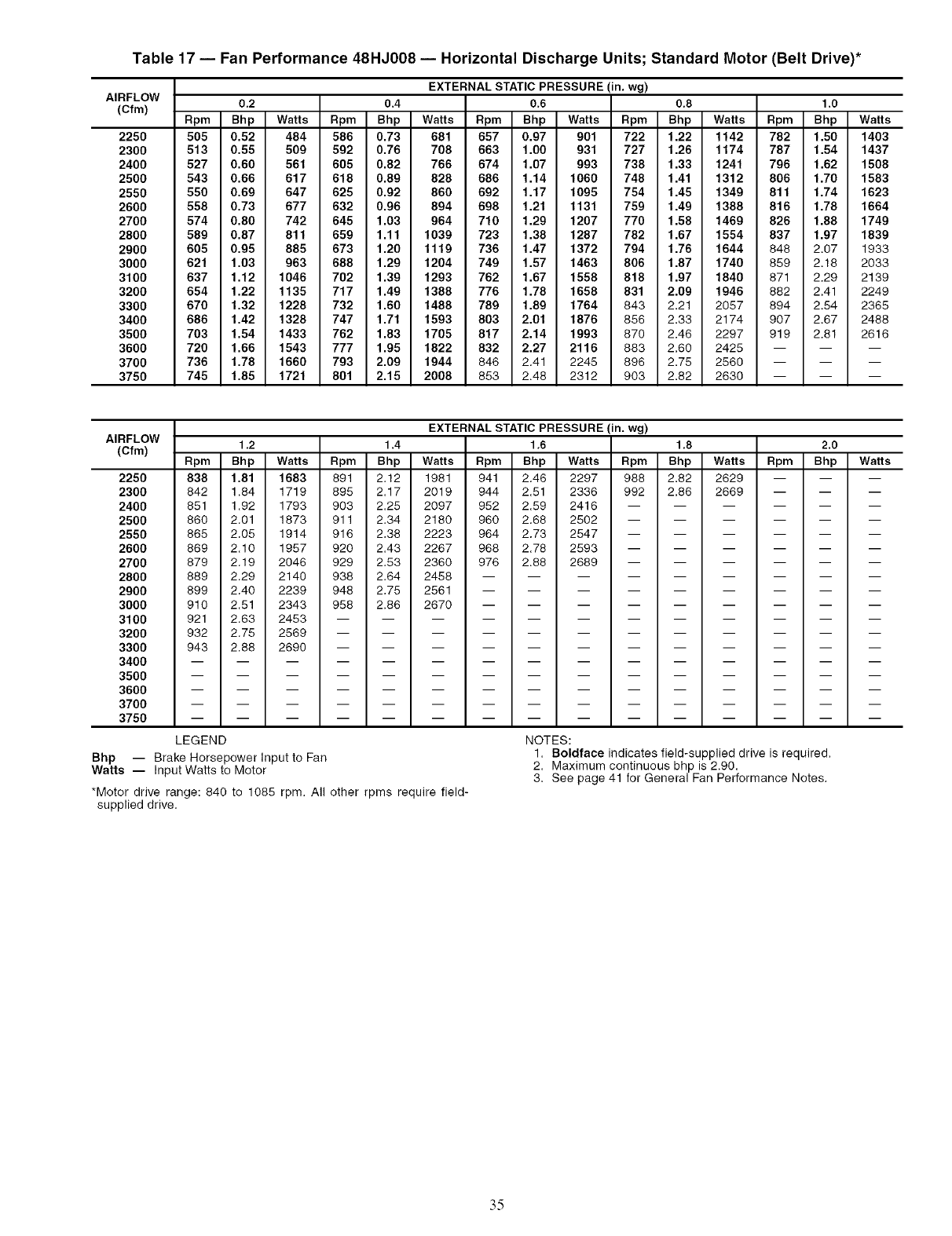
Table 17 -- Fan Performance 48HJ008 -- Horizontal Discharge Units; Standard Motor (Belt Drive)*
AIRFLOW
(Cfm)
2250
2300
2400
2500
2550
2600
2700
2800
2900
3000
3100
3200
3300
3400
3500
3600
3700
3750
EXTERNAL STATIC PRESSURE (in. wg)
0.2 0.4 0.6 0.8 1.0
Rpm Bhp Watts Rpm Bhp Watts Rpm Bhp Watts Rpm Bhp Watts Rpm Bhp Watts
505 0.52 484 586 0.73 681 657 0.97 901 722 1.22 1142 782 1.50 1403
513 0.55 509 592 0.76 708 663 1.00 931 727 1.26 1174 787 1.54 1437
527 0.60 561 605 0.82 766 674 1.07 993 738 1.33 1241 796 1.62 1508
543 0.66 617 618 0.89 828 686 1.14 1060 748 1.41 1312 806 1.70 1583
550 0.69 647 625 0.92 860 692 1.17 1095 754 1.45 1349 811 1.74 1623
558 0.73 677 632 0.96 894 698 1.21 1131 759 1.49 1388 816 1.78 1664
574 0.80 742 645 1.03 964 710 1.29 1207 770 1.58 1469 826 1.88 1749
589 0.87 811 659 1.11 1039 723 1.38 1287 782 1.67 1554 837 1.97 1839
605 0.95 885 673 1.20 1119 736 1.47 1372 794 1.76 1644 848 2.07 1933
621 1.03 963 688 1.29 1204 749 1.57 1463 806 1.87 1740 859 2.18 2033
637 1.12 1046 702 1.39 1293 762 1.67 1558 818 1.97 1840 871 2.29 2139
654 1.22 1135 717 1.49 1388 776 1.78 1658 831 2.09 1946 882 2.41 2249
670 1.32 1228 732 1.60 1488 789 1.89 1764 843 2.21 2057 894 2.54 2365
686 1.42 1328 747 1.71 1593 803 2.01 1876 856 2.33 2174 907 2.67 2488
703 1.54 1433 762 1.83 1705 817 2.14 1993 870 2.46 2297 919 2.81 2616
720 1.66 1543 777 1.95 1822 832 2.27 2116 883 2.60 2425 -- -- --
736 1.78 1660 793 2.09 1944 846 2.41 2245 896 2.75 2560 -- -- --
745 1.85 1721 801 2.15 2008 853 2.48 2312 903 2.82 2630 -- -- --
AIRFLOW
(Cfm)
2250
2300
2400
2500
2550
2600
2700
2800
2900
3000
3100
3200
3300
3400
3500
3600
3700
3750
EXTERNAL STATIC PRESSURE (in. wg)
1.2 1.4 1,6 1,8 2,0
Rpm Bhp Watts Rpm Bhp Watts Rpm Bhp Watts Rpm Bhp Watts Rpm Bhp Watts
838 1.81 1683 891 2.12 1981 941 2.46 2297 988 2.82 2629 --
842 1.84 1719 895 2.17 2019 944 2.51 2336 992 2.86 2669 --
m m
m m
851 1.92 1793 903 2.25 2097 952 2.59 2416 ......
860 2.01 1873 911 2.34 2180 960 2.68 2502 ......
865 2.05 1914 916 2.38 2223 964 2.73 2547 ......
869 2.10 1957 920 2.43 2267 968 2.78 2593 ......
879 2.19 2046 929 2.53 2360 976 2.88 2689 ......
889 2.29 2140 938 2.64 2458 .........
899 2.40 2239 948 2.75 2561 .........
910 2.51 2343 958 2.86 2670 .........
921 2.63 2453 ............
932 2.75 2569 ............
943 2.88 2690 ............
LEGEND
Bhp -- Brake Horsepower Input to Fan
Watts -- Input Watts to Motor
*Motor drive range: 840 to 1085 rpm. All other rpms require field-
supplied drive.
NOTES:
1. Boldface indicates field-supplied drive is required.
2. Maximum continuous bhp is 2.90.
3. See page 41 for General Fan Performance Notes.
.3.5
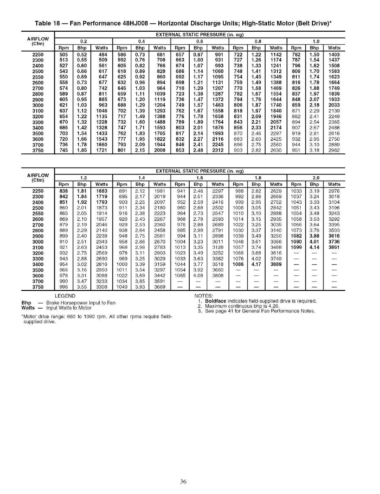
Table 18 -- Fan Performance 48HJ008 -- Horizontal Discharge Units; High-Static Motor (Belt Drive)*
AIRFLOW
(Cfm)
2250
2300
2400
2500
2550
2600
2700
2800
2900
3000
3100
3200
3300
3400
3500
3600
3700
3750
EXTERNAL STATIC PRESSURE (in. wg)
0.2 0.4 0.6 0.8 1.0
Rpm Bhp Watts Rpm Bhp Watts Rpm Bhp Watts Rpm Bhp Watts Rpm Bhp Watts
505 0.52 484 586 0.73 681 657 0.97 901 722 1.22 1142 782 1.50 1403
513 0.55 509 592 0.76 708 663 1.00 931 727 1.26 1174 787 1.54 1437
527 0.60 561 605 0.82 766 674 1.07 993 738 1.33 1241 796 1.62 1508
543 0.66 617 618 0.89 828 686 1.14 1060 748 1.41 1312 806 1.70 1583
550 0.69 647 625 0.92 860 692 1.17 1095 754 1.45 1349 811 1.74 1623
558 0.73 677 632 0.96 894 698 1.21 1131 759 1.49 1388 816 1.78 1664
574 0.80 742 645 1.03 964 710 1.29 1207 770 1.58 1469 826 1.88 1749
589 0.87 811 659 1.11 1039 723 1.38 1287 782 1.67 1554 837 1.97 1839
605 0.95 885 673 1.20 1119 736 1.47 1372 794 1.76 1644 848 2.07 1933
621 1.03 963 688 1.29 1204 749 1.57 1463 806 1.87 1740 859 2.18 2033
637 1.12 1046 702 1.39 1293 762 1.67 1558 818 1.97 1840 871 2.29 2139
654 1.22 1135 717 1.49 1388 776 1.78 1658 831 2.09 1946 882 2.41 2249
670 1.32 1228 732 1.60 1488 789 1.89 1764 843 2.21 2057 894 2.54 2365
686 1.42 1328 747 1.71 1593 803 2.01 1876 856 2.33 2174 907 2.67 2488
703 1.54 1433 762 1.83 1705 817 2.14 1993 870 2.46 2297 919 2.81 2616
720 1.66 1543 777 1.95 1822 832 2.27 2116 883 2.60 2425 932 2.95 2750
736 1.78 1660 793 2.09 1944 846 2.41 2245 896 2.75 2560 944 3.10 2889
745 1.85 1721 801 2.15 2008 853 2.48 2312 903 2.82 2630 951 3.18 2962
AIRFLOW
(Cfm) Rpm
2250 838
2300 842
2400 851
2500 860
2550 865
2600 869
2700 879
2800 889
2900 899 2.40
3000 910 2.51
3100 921 2.63
3200 932 2.75
3300 943 2.88
3400 954 3.02
3500 966 3.16
3600 978 3.31
3700 990 3.47
3750 996 3.55
LEGEND
EXTERNAL STATIC PRESSURE (in, wg)
1.2 1,4 1.6 1,8 2.0
Bhp Watts Rpm Bhp Watts Rpm Bhp Watts Rpm Bhp Watts Rpm Bhp Watts
1.81 1683 891 2.12 1981 941 2.46 2297 988 2.82 2629 1033 3.19 2976
1.84 1719 895 2.17 2019 944 2.51 2336 992 2.86 2669 1037 3.24 3018
1.92 1793 903 2.25 2097 952 2.59 2416 999 2.95 2752 1043 3.33 3104
2.01 1873 911 2.34 2180 960 2.68 2502 1006 3.05 2842 1051 3.43 3196
2.05 1914 916 2.38 2223 964 2.73 2547 1010 3.10 2888 1054 3.48 3243
2.10 1957 920 2.43 2267 968 2.78 2593 1014 3.15 2935 1058 3.53 3292
2.19 2046 929 2.53 2360 976 2.88 2689 1022 3.25 3035 1066 3.64 3395
2.29 2140 938 2.64 2458 985 2.99 2791 1030 3.37 3140 1073 3.76 3503
2239 948 2.75 2561 994 3.11 2898 1039 3.49 3250 1082 3.88 3616
2343 958 2.86 2670 1004 3.23 3011 1048 3.61 3366 1090 4.01 3736
2453 968 2.98 2783 1013 3.35 3128 1057 3.74 3488 1099 4.14 3861
2569 978 3.11 2903 1023 3.49 3252 1066 3.88 3616 -- -- --
2690 989 3.25 3029 1033 3.63 3382 1076 4.02 3749 -- -- --
2816 1000 3.39 3159 1044 3.77 3518 1086 4.17 3889 -- -- --
2950 1011 3.54 3297 1054 3.92 3660 ......
3088 1022 3.69 3442 1065 4.08 3808 ......
3233 1034 3.85 3591 .........
3308 1040 3.93 3669 .........
Bhp -- Brake Horsepower Input to Fan
Watts -- Input Watts to Motor
*Motor drive range: 860 to 1080 rpm.
supplied drive.
NOTES:
All other rpms require field-
1. Boldface indicates field-supplied drive is required.
2. Maximum continuous bhp is 4.20.
3. See page 41 for General Fan Performance Notes.
36
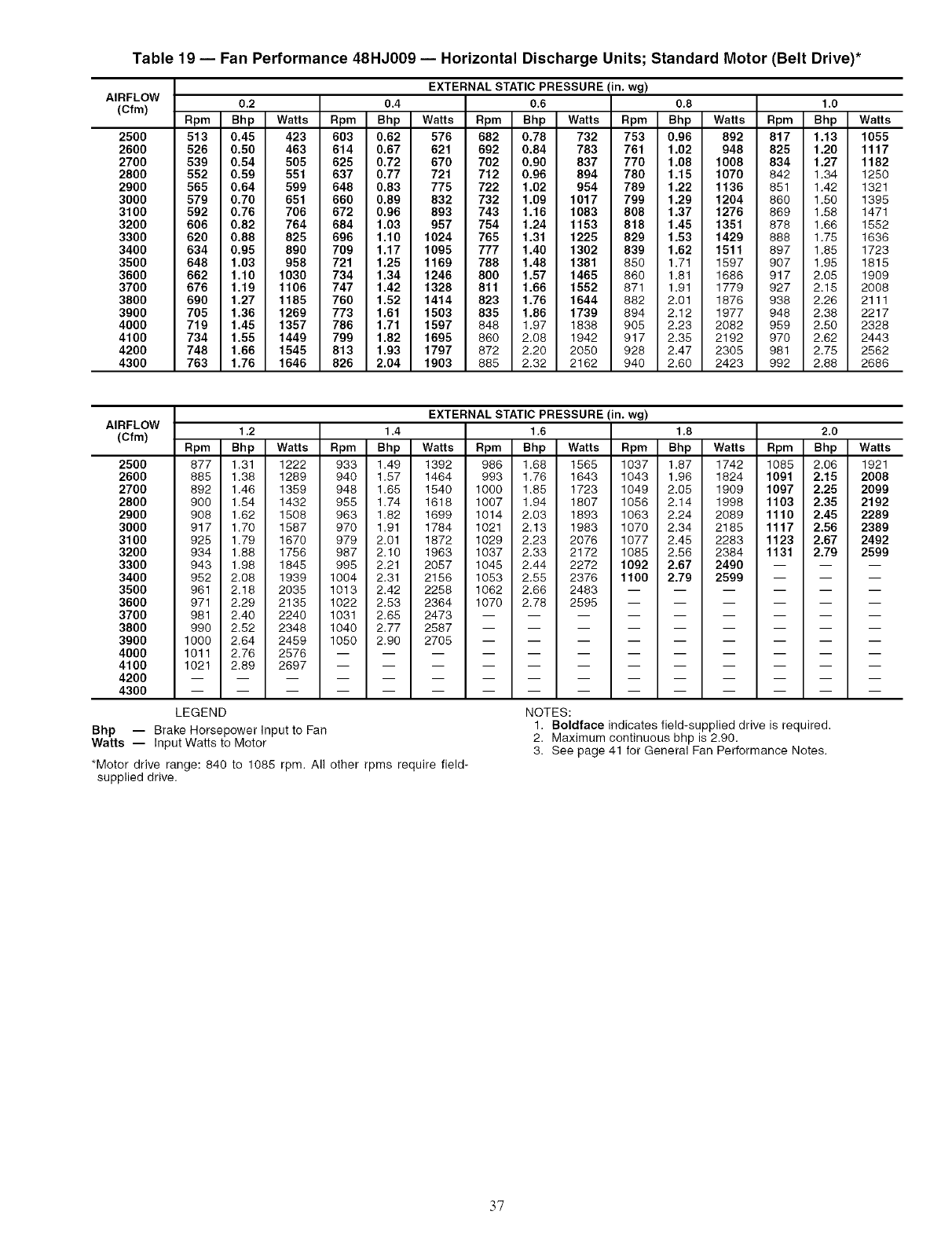
Table 19 -- Fan Performance 48HJ009 -- Horizontal Discharge Units; Standard Motor (Belt Drive)*
AIRFLOW
(Cfm)
2500
2600
2700
2800
2900
3000
3100
3200
3300
3400
3500
3600
3700
3800
3900
4000
4100
4200
4300
EXTERNAL STATIC PRESSURE (in. wg)
0.2 0.4 0.6 0.8 1.0
Rpm Bhp Watts Rpm Bhp Watts Rpm Bhp Watts Rpm Bhp Watts Rpm Bhp Watts
513 0.45 423 603 0.62 576 682 0.78 732 753 0.96 892 817 1.13 1055
526 0.50 463 614 0.67 621 692 0.84 783 761 1.02 948 825 1.20 1117
539 0.54 505 625 0.72 670 702 0.90 837 770 1.08 1008 834 1.27 1182
552 0.59 551 637 0.77 721 712 0.96 894 780 1.15 1070 842 1.34 1250
565 0.64 599 648 0.83 775 722 1.02 954 789 1.22 1136 851 1.42 1321
579 0.70 651 660 0.89 832 732 1.09 1017 799 1.29 1204 860 1.50 1395
592 0.76 706 672 0.96 893 743 1.16 1083 808 1.37 1276 869 1.58 1471
606 0.82 764 684 1.03 957 754 1.24 1153 818 1.45 1351 878 1.66 1552
620 0.88 825 696 1.10 1024 765 1.31 1225 829 1.53 1429 888 1.75 1636
634 0.95 890 709 1.17 1095 777 1.40 1302 839 1.62 1511 897 1.85 1723
648 1.03 958 721 1.25 1169 788 1.48 1381 850 1.71 1597 907 1.95 1815
662 1.10 1030 734 1.34 1246 800 1.57 1465 860 1.81 1686 917 2.05 1909
676 1.19 1106 747 1.42 1328 811 1.66 1552 871 1.91 1779 927 2.15 2008
690 1.27 1185 760 1.52 1414 823 1.76 1644 882 2.01 1876 938 2.26 2111
705 1.36 1269 773 1.61 1503 835 1.86 1739 894 2.12 1977 948 2.38 2217
719 1.45 1357 786 1.71 1597 848 1.97 1838 905 2.23 2082 959 2.50 2328
734 1.55 1449 799 1.82 1695 860 2.08 1942 917 2.35 2192 970 2.62 2443
748 1.66 1545 813 1.93 1797 872 2.20 2050 928 2.47 2305 981 2.75 2562
763 1.76 1646 826 2.04 1903 885 2.32 2162 940 2.60 2423 992 2.88 2686
AIRFLOW
(Cfm)
2500
2600
2700
2800
2900
3000
3100
3200
3300
3400
3500
3600
3700
3800
3900
4000
4100
4200
4300
EXTERNAL STATIC PRESSURE (in. wg)
1.2 1,4 1,6 1,8 2,0
Rpm Bhp Watts Rpm Bhp Watts Rpm Bhp Watts Rpm Bhp Watts Rpm Bhp Watts
877 1.31 1222 933 1.49 1392 986 1.68 1565 1037 1.87 1742 1085 2.06 1921
885 1.38 1289 940 1.57 1464 993 1.76 1643 1043 1.96 1824 1091 2.15 2008
892 1.46 1359 948 1.65 1540 1000 1.85 1723 1049 2.05 1909 1097 2.25 2099
900 1.54 1432 955 1.74 1618 1007 1.94 1807 1056 2.14 1998 1103 2.35 2192
908 1.62 1508 963 1.82 1699 1014 2.03 1893 1063 2.24 2089 1110 2.45 2289
917 1.70 1587 970 1.91 1784 1021 2.13 1983 1070 2.34 2185 1117 2.56 2389
925 1.79 1670 979 2.01 1872 1029 2.23 2076 1077 2.45 2283 1123 2.67 2492
934 1.88 1756 987 2.10 1963 1037 2.33 2172 1085 2.56 2384 1131 2.79 2599
943 1.98 1845 995 2.21 2057 1045 2.44 2272 1092 2.67 2490 -- -- --
952 2.08 1939 1004 2.31 2156 1053 2.55 2376 1100 2.79 2599 -- -- --
961 2.18 2035 1013 2.42 2258 1062 2.66 2483 ......
971 2.29 2135 1022 2.53 2364 1070 2.78 2595 ......
981 2.40 2240 1031 2.65 2473 .........
990 2.52 2348 1040 2.77 2587 .........
1000 2.64 2459 1050 2.90 2705 .........
1011 2.76 2576 ............
1021 2.89 2697 ............
LEGEND
Bhp -- Brake Horsepower Input to Fan
Watts -- Input Watts to Motor
*Motor drive range: 840 to 1085 rpm. All other rpms require field-
supplied drive.
NOTES:
1. Boldface indicates field-supplied drive is required.
2. Maximum continuous bhp is 2.90.
3. See page 41 for General Fan Performance Notes.
37
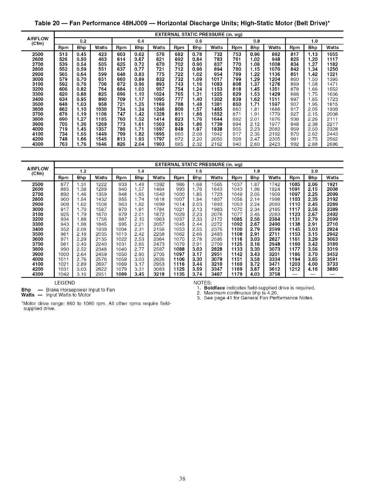
Table 20 -- Fan Performance 48HJ009 -- Horizontal Discharge Units; High-Static Motor (Belt Drive)*
AIRFLOW
(Cfm)
2500
2600
2700
2800
2900
3000
3100
3200
3300
3400
3500
3600
3700
3800
3900
4000
4100
4200
4300
EXTERNAL STATIC PRESSURE (in. wg)
0.2 0.4 0.6 0.8 1.0
Rpm Bhp Watts Rpm Bhp Watts Rpm Bhp Watts Rpm Bhp Watts Rpm Bhp Watts
513 0.45 423 603 0.62 576 682 0.78 732 753 0.96 892 817 1.13 1055
526 0.50 463 614 0.67 621 692 0.84 783 761 1.02 948 825 1.20 1117
539 0.54 505 625 0.72 670 702 0.90 837 770 1.08 1008 834 1.27 1182
552 0.59 551 637 0.77 721 712 0.96 894 780 1.15 1070 842 1.34 1250
565 0.64 599 648 0.83 775 722 1.02 954 789 1.22 1136 851 1.42 1321
579 0.70 651 660 0.89 832 732 1.09 1017 799 1.29 1204 860 1.50 1395
592 0.76 706 672 0.96 893 743 1.16 1083 808 1.37 1276 869 1.58 1471
606 0.82 764 684 1.03 957 754 1.24 1153 818 1.45 1351 878 1.66 1552
620 0.88 825 696 1.10 1024 765 1.31 1225 829 1.53 1429 888 1.75 1636
634 0.95 890 709 1.17 1095 777 1.40 1302 839 1.62 1511 897 1.85 1723
648 1.03 958 721 1.25 1169 788 1.48 1381 850 1.71 1597 907 1.95 1815
662 1.10 1030 734 1.34 1246 800 1.57 1465 860 1.81 1686 917 2.05 1909
676 1.19 1106 747 1.42 1328 811 1.66 1552 871 1.91 1779 927 2.15 2008
690 1.27 1185 760 1.52 1414 823 1.76 1644 882 2.01 1876 938 2.26 2111
705 1.36 1269 773 1.61 1503 835 1.86 1739 894 2.12 1977 948 2.38 2217
719 1.45 1357 786 1.71 1597 848 1.97 1838 905 2.23 2082 959 2.50 2328
734 1.55 1449 799 1.82 1695 860 2.08 1942 917 2.35 2192 970 2.62 2443
748 1.66 1545 813 1.93 1797 872 2.20 2050 928 2.47 2305 981 2.75 2562
763 1.76 1646 826 2.04 1903 885 2.32 2162 940 2.60 2423 992 2.88 2686
AIRFLOW
(Cfm)
2500
2600
2700
2800
2900
3000
3100
3200
3300
3400
3500
3600
3700
3800
3900
4000
4100
4200
4300
Bhp -- Brake Horsepower Input to Fan
Watts -- Input Watts to Motor
*Motor drive range: 860 to 1080 rpm. All other rpms require field-
supplied drive.
EXTERNAL STATIC PRESSURE (in, wg)
1,2 1,4 1.6 1,8 2,0
Rpm Bhp Watts Rpm Bhp Watts Rpm Bhp Watts Rpm Bhp Watts Rpm Bhp Watts
877 1.31 1222 933 1.49 1392 986 1.68 1565 1037 1.87 1742 1085 2.06 1921
885 1.38 1289 940 1.57 1464 993 1.76 1643 1043 1.96 1824 1091 2.15 2008
892 1.46 1359 948 1.65 1540 1000 1.85 1723 1049 2.05 1909 1097 2.25 2099
900 1.54 1432 955 1.74 1618 1007 1.94 1807 1056 2.14 1998 1103 2.35 2192
908 1.62 1508 963 1.82 1699 1014 2.03 1893 1063 2.24 2089 1110 2.45 2289
917 1.70 1587 970 1.91 1784 1021 2.13 1983 1070 2.34 2185 1117 2.56 2389
925 1.79 1670 979 2.01 1872 1029 2.23 2076 1077 2.45 2283 1123 2.67 2492
934 1.88 1756 987 2.10 1963 1037 2.33 2172 1085 2.56 2384 1131 2.79 2599
943 1.98 1845 995 2.21 2057 1045 2.44 2272 1092 2.67 2490 1138 2.91 2710
952 2.08 1939 1004 2.31 2156 1053 2.55 2376 1100 2.79 2599 1145 3.03 2824
961 2.18 2035 1013 2.42 2258 1062 2.66 2483 1108 2.91 2711 1153 3.15 2942
971 2.29 2135 1022 2.53 2364 1070 2.78 2595 1116 3.03 2827 1161 3.29 3063
981 2.40 2240 1031 2.65 2473 1079 2.91 2709 1125 3.16 2948 1169 3.42 3189
990 2.52 2348 1040 2.77 2587 1088 3.03 2828 1133 3.30 3073 1177 3.56 3319
lOOO 2.64 2459 1050 2.90 2705 1097 3.17 2951 1142 3.43 3201 1186 3.70 3452
1011 2.76 2576 1059 3.03 2826 1106 3.30 3079 1151 3.58 3334 1194 3.85 3591
1021 2.89 2697 1069 3.17 2953 1116 3.44 3210 1160 3.72 3471 1203 4.00 3733
1031 3.03 2822 1079 3.31 3083 1125 3.59 3347 1169 3.87 3612 1212 4.16 3880
1042 3.16 2951 1089 3.45 3218 1135 3.74 3487 1179 4.03 3758 -- -- --
LEGEND NOTES:
1. Boldface indicates field-supplied drive is required.
2. Maximum continuous bhp is 4.20.
3. See page 41 for General Fan Performance Notes.
38
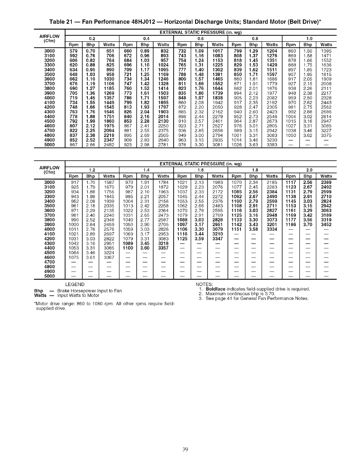
Table 21 -- Fan Performance 48HJ012 -- Horizontal Discharge Units; Standard Motor (Belt Drive)*
AIRFLOW
(Cfm)
3O0O
3100
3200
3300
3400
3500
3600
3700
3800
3900
4000
4100
4200
4300
4400
4500
4600
4700
4800
4900
5000
EXTERNAL STATIC PRESSURE (in. wg)
0.2 0.4 0.6 0.8 1.0
Rpm Bhp Watts Rpm Bhp Watts Rpm Bhp Watts Rpm Bhp Watts Rpm Bhp Watts
579 0.70 651 660 0.89 832 732 1.09 1017 799 1.29 1204 860 1.50 1395
592 0.76 706 672 0.96 893 743 1.16 1083 808 1.37 1276 869 1.58 1471
606 0.82 764 684 1.03 957 754 1.24 1153 818 1.45 1351 878 1.66 1552
620 0.88 825 696 1.10 1024 765 1.31 1225 829 1.53 1429 888 1.75 1636
634 0.95 890 709 1.17 1095 777 1.40 1302 839 1.62 1511 897 1.85 1723
648 1.03 958 721 1.25 1169 788 1.48 1381 850 1.71 1597 907 1.95 1815
662 1.10 1030 734 1.34 1246 800 1.57 1465 860 1.81 1686 917 2.05 1909
676 1.19 1106 747 1.42 1328 811 1.66 1552 671 1.91 1779 927 2.15 2008
690 1.27 1185 760 1.52 1414 823 1.76 1644 882 2.01 1876 938 2.26 2111
705 1.36 1269 773 1.61 1503 835 1.86 1739 894 2.12 1977 948 2.38 2217
719 1.45 1357 786 1.71 1597 848 1.97 1838 905 2.23 2082 959 2.50 2328
734 1.55 1449 799 1.82 1695 860 2.08 1942 917 2.35 2192 970 2.62 2443
748 1.66 1545 813 1.93 1797 872 2.20 2050 928 2.47 2305 981 2.75 2562
763 1.76 1646 826 2.04 1903 885 2.32 2162 940 2.60 2423 992 2.88 2686
778 1.88 1751 840 2.16 2014 898 2.44 2279 952 2.73 2546 1004 3.02 2814
792 1.99 1860 853 2.28 2130 910 2.57 2401 964 2.87 2673 1015 3.16 2947
807 2.12 1975 667 2.41 2250 923 2.71 2527 976 3.01 2805 1027 3.31 3085
822 2.25 2094 881 2.55 2375 936 2.85 2858 989 3.15 2942 1038 3.46 3227
837 2.38 2218 895 2.69 2505 949 3.00 2794 1001 3.31 3083 1050 3.82 3375
852 2.52 2347 909 2.83 2640 963 3.15 2935 1014 3.46 3230 -- -- --
867 2.66 2482 923 2.98 2781 976 3.30 3081 1026 3.63 3383 -- -- --
AIRFLOW
(Cfm)
300O
3100
3200
3300
3400
3500
3600
3700
3800
3900
4000
4100
4200
4300
4400
4500
4600
4700
4800
4900
5000
EXTERNAL STATIC PRESSURE (in. wg)
1.2 1,4 1,6 1,8 2,0
Rpm Bhp Watts Rpm Bhp Watts Rpm Bhp Watts Rpm Bhp Watts Rpm Bhp Watts
917 1.70 1587 970 1.91 1784 1021 2.13 1983 1070 2.34 2185 1117 2.56 2389
925 1.79 1670 979 2.01 1872 1029 2.23 2076 1077 2.45 2283 1123 2.67 2492
934 1.88 1756 987 2.10 1963 1037 2.33 2172 1085 2.56 2384 1131 2.79 2599
943 1.98 1845 995 2.21 2057 1045 2.44 2272 1092 2.67 2490 1138 2.91 2710
952 2.08 1939 1004 2.31 2156 1053 2.55 2376 1100 2.79 2599 1145 3.03 2824
981 2.18 2035 1013 2.42 2258 1062 2.68 2483 1108 2.91 2711 1153 3.15 2942
971 2.29 2135 1022 2.53 2364 1070 2.78 2595 1116 3.03 2827 1161 3.29 3063
981 2.40 2240 1031 2.65 2473 1079 2.91 2709 1125 3.16 2948 1169 3.42 3189
990 2.52 2348 1040 2.77 2587 1088 3.03 2828 1133 3.30 3073 1177 3.56 3319
1000 2.64 2459 1050 2.90 2705 1097 3.17 2951 1142 3.43 3201 1186 3.70 3452
1011 2.76 2576 1059 3.03 2826 1106 3.30 3079 1151 3.58 3334 -- -- --
1021 2.89 2697 1069 3.17 2953 1116 3.44 3210 ......
1031 3.03 2822 1079 3.31 3083 1125 3.59 3347 ......
1042 3.16 2951 1089 3.45 3218 .........
1053 3.31 3085 1100 3.60 3357 .........
1064 3.46 3224 ............
1075 3.61 3367 ............
LEGEND
Bhp -- Brake Horsepower Input to Fan
Watts -- Input Watts to Motor
*Motor drive range: 860 to 1080 rpm. All other rpms require field-
supplied drive.
NOTES:
1. Boldface indicates field-supplied drive is required.
2. Maximum continuous bhp is 3.70.
3. See page 41 for General Fan Performance Notes.
39
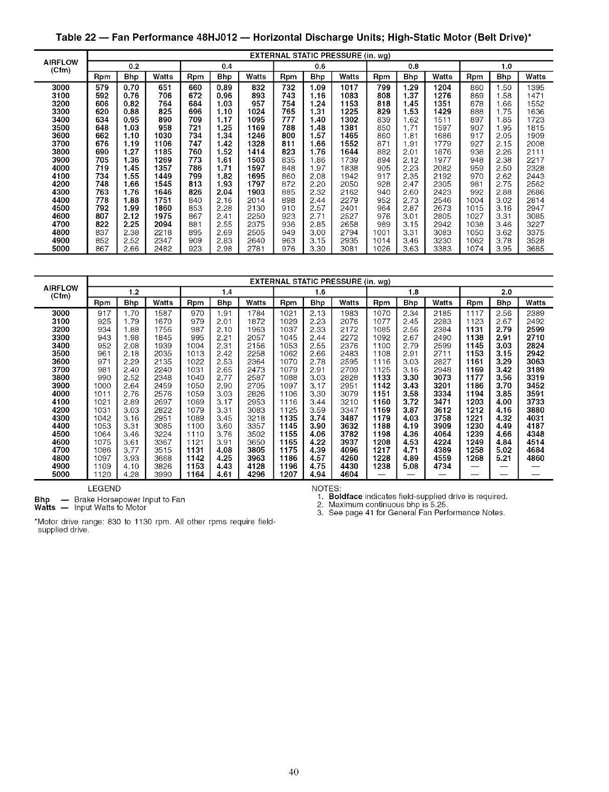
Table 22 -- Fan Performance 48HJ012 -- Horizontal Discharge Units; High-Static Motor (Belt Drive)*
AIRFLOW
(Cfm)
3O00
3100
3200
3300
3400
3500
3600
3700
3800
3900
4000
4100
4200
4300
4400
4500
4600
4700
4800
4900
5000
EXTERNAL STATIC PRESSURE (in. wg)
0.2 0.4 0.6 0.8 1.0
Rpm Bhp Watts Rpm Bhp Watts Rpm Bhp Watts Rpm Bhp Watts Rpm Bhp Watts
579 0.70 651 660 0.89 832 732 1.09 1017 799 1.29 1204 860 1.50 1395
592 0.76 706 672 0.96 893 743 1.16 1083 808 1.37 1276 869 1.58 1471
606 0.82 764 684 1.03 957 754 1.24 1153 818 1.45 1351 878 1.66 1552
620 0.88 825 696 1.10 1024 765 1.31 1225 829 1.53 1429 888 1.75 1636
634 0.95 890 709 1.17 1095 777 1.40 1302 839 1.62 1511 897 1.85 1723
648 1.03 958 721 1.25 1169 788 1.48 1381 850 1.71 1597 907 1.95 1815
662 1.10 1030 734 1.34 1246 800 1.57 1465 860 1.81 1686 917 2.05 1909
676 1.19 1106 747 1.42 1328 811 1.66 1552 871 1.91 1779 927 2.15 2008
690 1.27 1185 760 1.52 1414 823 1.76 1644 882 2.01 1876 938 2.26 2111
705 1.36 1269 773 1.61 1503 835 1.86 1739 894 2.12 1977 948 2.38 2217
719 1.45 1357 786 1.71 1597 848 1.97 1838 905 2.23 2082 959 2.50 2328
734 1.55 1449 799 1.82 1695 860 2.08 1942 917 2.35 2192 970 2.62 2443
748 1.66 1545 813 1.93 1797 872 2.20 2050 928 2.47 2305 981 2.75 2562
763 1.76 1646 826 2.04 1903 885 2.32 2162 940 2.60 2423 992 2.88 2686
778 1.88 1751 840 2.16 2014 898 2.44 2279 952 2.73 2546 1004 3.02 2814
792 1.99 1860 853 2.28 2130 910 2.57 2401 964 2.87 2673 1015 3.16 2947
807 2.12 1975 867 2.41 2250 923 2.71 2527 976 3.01 2805 1027 3.31 3085
822 2.25 2094 881 2.55 2375 936 2.85 2658 989 3.15 2942 1038 3.46 3227
837 2.38 2218 895 2.69 2505 949 3.00 2794 1001 3.31 3083 1050 3.62 3375
852 2.52 2347 909 2.83 2640 963 3.15 2935 1014 3.46 3230 1062 3.78 3528
867 2.66 2482 923 2.98 2781 976 3.30 3081 1026 3.63 3383 1074 3.95 3685
AIRFLOW
(Cfm)
3000
3100
3200
3300
3400
3500
3600
3700
3800
3900
4000
4100
4200
4300
4400
4500
4600
4700
4800
4900
5000
Bhp -- Brake Horsepower Input to Fan
Watts -- Input Watts to Motor
EXTERNAL STATIC PRESSURE (in. wg)
1.2 1,4 1.6 1,8 2.0
Rpm Bhp Watts Rpm Bhp Watts Rpm Bhp Watts Rpm Bhp Watts Rpm Bhp Watts
917 1.70 1587 970 1.91 1784 1021 2.13 1983 1070 2.34 2185 1117 2.56 2389
925 1.79 1670 979 2.01 1872 1029 2.23 2076 1077 2.45 2283 1123 2.67 2492
934 1.88 1756 987 2.10 1963 1037 2.33 2172 1085 2.56 2384 1131 2.79 2599
943 1.98 1845 995 2.21 2057 1045 2.44 2272 1092 2.67 2490 1138 2.91 2710
952 2.08 1939 1004 2.31 2156 1053 2.55 2376 1100 2.79 2599 1145 3.03 2824
961 2.18 2035 1013 2.42 2258 1062 2.66 2483 1108 2.91 2711 1153 3.15 2942
971 2.29 2135 1022 2.53 2364 1070 2.78 2595 1116 3.03 2827 1161 3.29 3063
981 2.40 2240 1031 2.65 2473 1079 2.91 2709 1125 3.16 2948 1169 3.42 3189
990 2.52 2348 1040 2.77 2587 1088 3.03 2828 1133 3.30 3073 1177 3.56 3319
1000 2.64 2459 1050 2.90 2705 1097 3.17 2951 1142 3.43 3201 1186 3.70 3452
1011 2.76 2576 1059 3.03 2826 1106 3.30 3079 1151 3.58 3334 1194 3.85 3591
1021 2.89 2697 1069 3.17 2953 1116 3.44 3210 1160 3.72 3471 1203 4.00 3733
1031 3.03 2822 1079 3.31 3083 1125 3.59 3347 1169 3.87 3612 1212 4.16 3880
1042 3.16 2951 1089 3.45 3218 1135 3.74 3487 1179 4.03 3758 1221 4.32 4031
1053 3.31 3085 1100 3.60 3357 1145 3.90 3632 1188 4.19 3909 1230 4.49 4187
1064 3.46 3224 1110 3.76 3502 1155 4.06 3782 1198 4.36 4064 1239 4.66 4348
1075 3.61 3367 1121 3.91 3650 1165 4.22 3937 1208 4.53 4224 1249 4.84 4514
1086 3.77 3515 1131 4.08 3805 1175 4.39 4096 1217 4.71 4389 1258 5.02 4684
1097 3.93 3668 1142 4.25 3963 1186 4.57 4260 1228 4.89 4559 1268 5.21 4860
1109 4.10 3826 1153 4.43 4128 1196 4.75 4430 1238 5.08 4734 -- -- --
1120 4.28 3990 1164 4.61 4296 1207 4.94 4604 ......
LEGEND NOTES:
1. Boldface indicates field-supplied drive is required.
2. Maximum continuous bhp is 5.25.
3. See page 41 for General Fan Performance Notes.
*Motor drive range: 830 to 1130 rpm. All other rpms require field-
supplied drive.
40
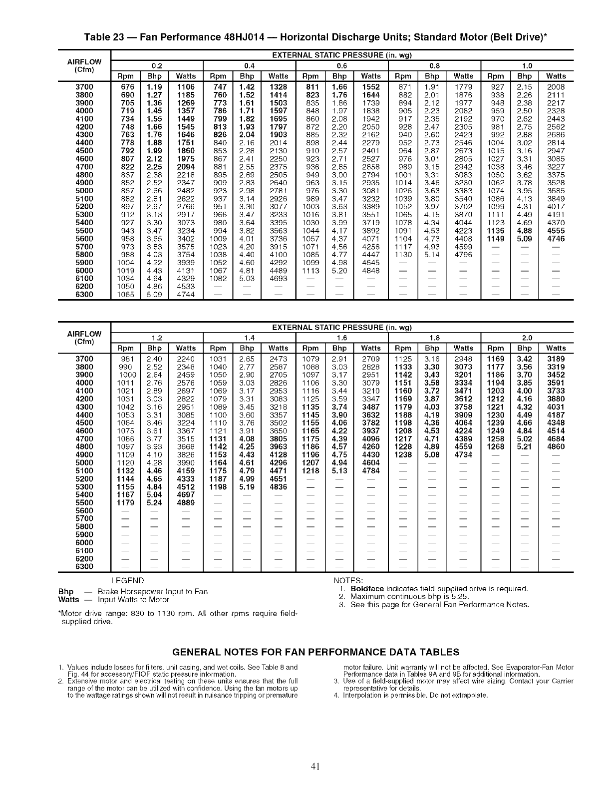
Table 23 -- Fan Performance 48HJ014 -- Horizontal Discharge Units; Standard Motor (Belt Drive)*
AIRFLOW
(Cfm)
37OO
3800
3900
4000
4100
4200
4300
4400
4500
4600
4700
4800
4900
5000
5100
5200
5300
5400
5500
5600
5700
5800
5900
6000
6100
6200
6300
EXTERNAL STATIC PRESSURE (in. wg)
0.2 0.4 0.6 0.8 1.0
Rpm Bhp Watts Rpm Bhp Watts Rpm Bhp Watts Rpm Bhp Watts Rpm Bhp Watts
676 1.19 1106 747 1.42 1328 811 1.66 1552 671 1.91 1779 927 2.15 2008
690 1.27 1185 760 1.52 1414 823 1.76 1644 882 2.01 1876 938 2.26 2111
705 1.36 1269 773 1.61 1503 835 1.86 1739 894 2.12 1977 948 2.38 2217
719 1.45 1357 786 1.71 1597 848 1.97 1838 905 2.23 2082 959 2.50 2328
734 1.55 1449 799 1.82 1695 860 2.08 1942 917 2.35 2192 970 2.62 2443
748 1.66 1545 813 1.93 1797 872 2.20 2050 928 2.47 2305 981 2.75 2562
763 1.76 1646 826 2.04 1903 885 2.32 2162 940 2.60 2423 992 2.88 2686
778 1.88 1751 840 2.16 2014 898 2.44 2279 952 2.73 2546 1004 3.02 2814
792 1.99 1860 853 2.28 2130 910 2.57 2401 984 2.87 2673 1015 3.16 2947
807 2.12 1975 867 2.41 2250 923 2.71 2527 976 3.01 2805 1027 3.31 3085
822 2.25 2094 881 2.55 2375 936 2.85 2658 989 3.15 2942 1038 3.46 3227
837 2.38 2218 895 2.69 2505 949 3.00 2794 1001 3.31 3083 1050 3.62 3375
852 2.52 2347 909 2.83 2640 963 3.15 2935 1014 3.46 3230 1062 3.78 3528
867 2.66 2482 923 2.98 2781 976 3.30 3081 1026 3.63 3383 1074 3.95 3685
882 2.81 2622 937 3.14 2928 989 3.47 3232 1039 3.80 3540 1088 4.13 3849
897 2.97 2766 951 3.30 3077 1003 3.63 3389 1052 3.97 3702 1099 4.31 4017
912 3.13 2917 968 3.47 3233 1016 3.81 3551 1065 4.15 3870 1111 4.49 4191
927 3.30 3073 980 3.64 3395 1030 3.99 3719 1078 4.34 4044 1123 4.69 4370
943 3.47 3234 994 3.82 3563 1044 4.17 3892 1091 4.53 4223 1136 4.88 4555
958 3.65 3402 1009 4.01 3738 1057 4.37 4071 1104 4.73 4408 1149 5.09 4746
973 3.83 3575 1023 4.20 3915 1071 4.56 4256 1117 4.93 4599 -- -- --
988 4.03 3754 1038 4.40 4100 1085 4.77 4447 1130 5.14 4796 -- -- --
1004 4.22 3939 1052 4.60 4292 1099 4.98 4645 ......
1019 4.43 4131 1067 4.81 4489 1113 5.20 4848 ......
1034 4.64 4329 1082 5.03 4693 .........
1050 4.86 4533 ............
1065 5.09 4744 ............
AIRFLOW
(Cfm)
370O
3800
3g00
4000
4100
4200
4300
4400
4500
4600
4700
4800
4900
5000
5100
5200
5300
5400
5500
5600
5700
5800
5900
6000
6100
6200
6300
EXTERNAL STATIC PRESSURE (in. wg)
1.2 1.4 1.6 1.8 2,0
Rpm Bhp Watts Rpm Bhp Watts Rpm Bhp Watts Rpm Bhp Watts Rpm Bhp Watts
981 2.40 2240 1031 2.65 2473 1079 2.91 2709 1125 3.18 2948 1169 3.42 3189
990 2.52 2348 1040 2.77 2587 1088 3.03 2828 1133 3.30 3073 1177 3.56 3319
1000 2.64 2459 1050 2.90 2705 1097 3.17 2951 1142 3.43 3201 1186 3.70 3452
1011 2.76 2576 1059 3.03 2826 1106 3.30 3079 1151 3.58 3334 1194 3.85 3591
1021 2.89 2697 1069 3.17 2953 1116 3.44 3210 1160 3.72 3471 1203 4.00 3733
1031 3.03 2822 1079 3.31 3083 1125 3.59 3347 1169 3.87 3612 1212 4.16 3880
1042 3.16 2951 1089 3.45 3218 1135 3.74 3487 1179 4.03 3758 1221 4.32 4031
1053 3.31 3085 1100 3.60 3357 1145 3.90 3632 1188 4.19 3909 1230 4.49 4187
1084 3.46 3224 1110 3.76 3502 1155 4.06 3782 1198 4.36 4064 1239 4.66 4348
1075 3.61 3367 1121 3.91 3650 1165 4.22 3937 1208 4.53 4224 1249 4.84 4514
1086 3.77 3515 1131 4.08 3805 1175 4.39 4096 1217 4.71 4389 1258 5.02 4684
1097 3.93 3688 1142 4.25 3963 1186 4.57 4260 1228 4.89 4559 1268 5.21 4860
1109 4.10 3826 1153 4.43 4128 1196 4.75 4430 1238 5.08 4734 --
1120 4.28 3990 1164 4.61 4296 1207 4.94 4604 --
1132 4.46 4159 1175 4.79 4471 1218 5.13 4784 --
1144 4.65 4333 1187 4.99 4651 -- --
1155 4.84 4512 1198 5.19 4836 -- --
m m
1167 5.04 4697 ............
1179 5.24 4889 ............
LEGEND
Bhp -- Brake Horsepower Input to Fan
Watts -- Input Watts to Motor
*Motor drive range: 830 to 1130 rpm. All other rpms require field-
supplied drive.
NOTES:
1. Boldface indicates field-supplied drive is required.
2. Maximum continuous bhp is 5.25.
3. See this page for General Fan Performance Notes.
GENERAL NOTES FOR FAN PERFORMANCE DATA TABLES
1. Values include losses for filters, unit casing, and wet coils. See Table 8 and
Fig. 44 for accessory/FlOP static pressure information.
2. Extensive motor and electrical testing on these units ensures that the full
range of the motor can be utilized with confidence. Using the fan motors up
to the wattage ratings shown will not result in nuisance tripping or premature
motor failure. Unit warranty will not be affected. See Evaporator-Fan Motor
Performance data in Tables 9A and 9B for additional information.
3. Use of a field-supplied motor may affect wire sizing. Contact your Carrier
representative for details.
4. Interpolation is permissible. Do not extrapolate.
4!
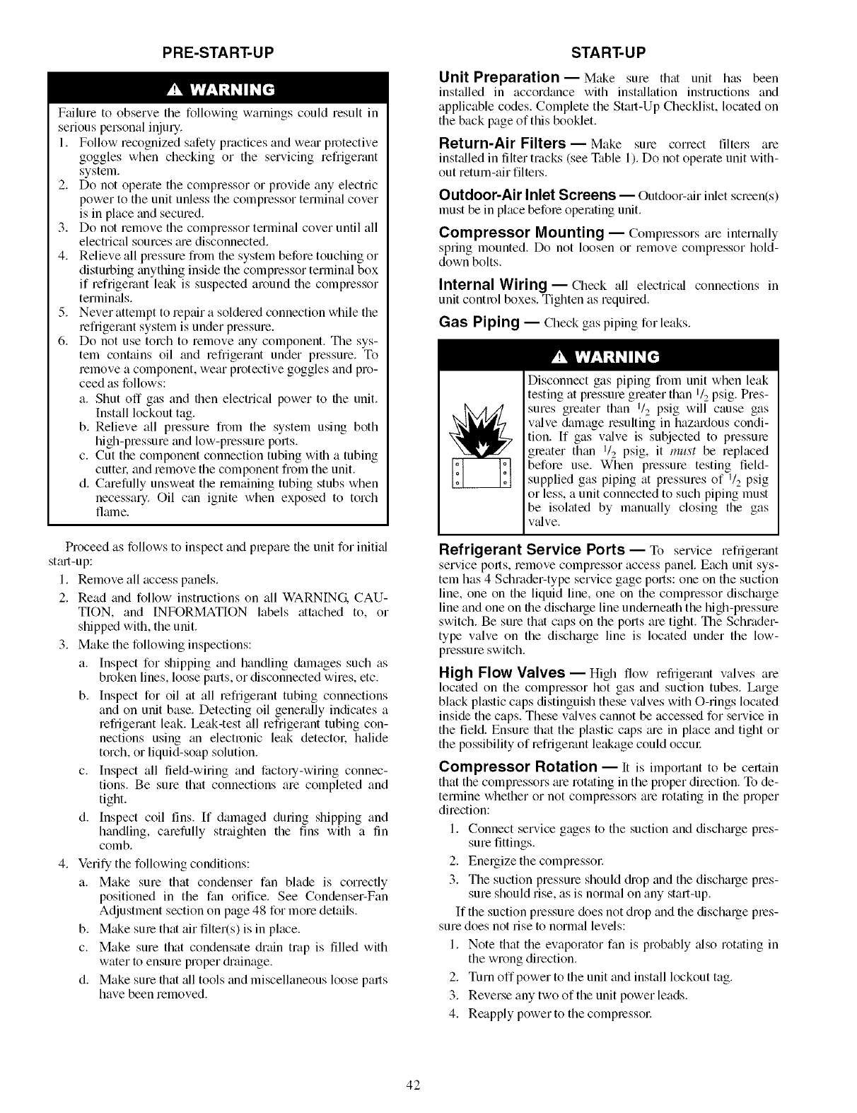
PRE-START-UP
F;filure to observe the following warnings could result in
serious personal injury.
1. Follow recognized safety practices and we;u protective
goggles when checking or the servicing refrigerant
system.
2. Do not operate the compressor or provide any electric
power to the unit unless the compressor terminal cover
is in place and secured.
3. Do not remove the compressor terminal cover until all
electrical sources _ue disconnected.
4. Relieve all pressure from file system before touching or
disturbing anything inside the compressor terminal box
if refrigerant leak is suspected around the compressor
termimds.
5. Never attempt to repair a soldered connection while the
refrigerant system is under pressure.
6. Do not use torch to remove any component. The sys-
tem cont_dns oil and refrigerant under pressure. To
remove a component, wear protective goggles and pro-
ceed as follows:
a. Shut off gas and then electrical power to the unit.
Install lockout tag.
b. Relieve all pressure from the system using both
high-pressure and low-pressure ports.
c. Cut the component connection tubing with a tubing
cuttel: and remove the component from the unit.
d. Carefully unsweat the remaining tubing stubs when
necessary. Oil can ignite when exposed to torch
flalne.
Proceed as follows to inspect and plepale the unit for initi_d
st_ut-up:
1. Remove all access panels.
2. Read and follow instructions on all WARNING CAU-
TION, and INFORMATION labels attached to, or
shipped with, the unit.
3. Make the following inspections:
a. Inspect for shipping and handling damages such as
broken lines, loose parts, or disconnected wires, etc.
b. Inspect for oil at all refrigerant tubing connections
and on unit base. Detecting oil generally indicates a
refrigerant leak. Leak-test all refiigemnt tubing con-
nections using an electronic leak detectol: halide
torch, or liquid-soap solution.
c. Inspect all tield-wiring and factoly-wiring connec-
tions. Be sure that connections are completed and
tight.
d. Inspect coil fins. If damaged during shipping and
handling, carefully straighten the fins with a tin
comb.
4. Verify the following conditions:
a. Make sure that condenser fan blade is correctly
positioned in the fan orifice. See Condenser-Fan
Adjustment section on page 48 for more details.
b. M_e sure that air filter(s) is in place.
c. Make sure that condensate drain trap is filled with
water to ensure proper di'ainage.
d. Make sure that all tools and miscellaneous loose parts
have been removed.
START-UP
Unit Preparation--Make sure that unit has been
installed in accordance with inst;dlation instructions and
applicable codes. Complete the Start-Up Checklist, located on
the back page of this booklet.
Return-Air Filters--Make sure correct filters are
inst_dled in tilter tracks (see Table 1). Do not operate unit with-
out return-air filters.
Outdoor-Air Inlet Screens -- Outdoor-;dr inlet screen(s)
must be in place befole operating unit.
Compressor Mounting- Compressorsare internally
spring mounted. Do not loosen or remove compressor hold-
down bolts.
Internal Wiring- Check all electric_d connections in
unit control boxes. Tighten as required.
Gas Piping -- Check gas piping for leaks.
Disconnect gas piping fiom unit when leak
testing at pressure greater than 1/2 psig. Pres-
sures greater than 1/2 psig will cause gas
valve damage resulting in hazardous condi-
tion. If gas valve is subjected to pressure
greater than I/2 psig, it must be replaced
before use. When pressure testing field-
supplied gas piping at pressures of 1/2 psig
or less, a unit connected to such piping must
be isolated by manually closing the gas
v_dve.
Refrigerant Service Ports-- To service refiigerant
service pofls, remove compressor access panel. Each unit sys-
tem has 4 Schrader-type service gage ports: one on the suction
line, one on the liquid line, one on the compressor discharge
line and one on the discharge line underneath the high-pressure
switch. Be sure that caps on the ports are tight. The Schrader-
type valve on the discharge line is located under the low-
pressure switch.
High Flow Valves- High flow refrigerant valves are
located on the compressor hot gas and suction tubes. Large
black plastic caps distinguish these wdves with O-rings located
inside the caps. These v;dves cannot be accessed for service in
the field. Ensure that the plastic caps me in place and tight or
the possibility of refrigerant leakage could occm:
Compressor Rotation -- It is important to be certain
that the compressors me rotating in the proper direction. To de-
termine whether or not compressors are rotating in the proper
direction:
1. Connect service gages to the suction and dischmge pres-
sure fittings.
2. Energize the compressol:
3. The suction pressure should diop and the discharge pres-
sure should rise, as is normal on any start-up.
If the suction pressure does not drop and the discharge pres-
sure does not rise to normal levels:
1. Note that the evaporator fan is probably also rotating in
the wrong direction.
2. Turn off power to the unit and install lockout tag.
3. Reverse any two of the unit power leads.
4. Reapply powerto the compressol:
42

Thesuctionanddischargepressurelevelsshouldnowmove
totheirnormalstart-uplevels.
When the compressors am rotating in the wrong direction,
the unit will have increased noise levels and will not pro-
vide heating and cooling. Compressor failure will occur if
the unit continues to operate in this condition.
Cooling -- To start unit, turn on main power supply. Set
system selector switch at COOL position and fan switch at
AUTO. position. Adjust thermostat to a setting below room
tempemtum. Compressor starts on closum of contactors.
Check unit charge. Refer to Refrigerant Ch_uge section on
page 48.
Reset thermostat at a position above room temperatum.
Compressor will shut off. Evaporator fan will shut off after
30-second delay.
TO SHUT OFF UNIT -- Set system switch at OFF position.
Resetting thermostat at a position above room temperatum
shuts unit off temponuily until space temperatum exceeds ther-
mostat setting. Units zue equipped with Cycle-LOC TM protec-
tion device. Unit shuts down on any safety trip and remains off;
an indicator light on the thermostat comes on. Check reason for
safety trip.
Compressor restart is accomplished by manual reset at the
thermostat by turning the selector switch to OFF position and
then to ON position.
Main Burners -- Main burners are factory set and should
requim no adjustment.
TO CHECK ignition of main burners and heating controls,
move thermostat set point above room temperatum and verily
that the burners light and evaporator fan is energized. After
ensuring that the unit continues to heat the building, lower the
thermostat setting below room tempemtum and verily that the
burners and evaporator fan turn off.
Refer to Table 24 for the con'ect orifice to use at high
altitudes.
NOTE: Upon a call for heat the main burners will remain on
for a minimum of 60 seconds.
Table 24 -- Altitude Compensation*
ELEVATION
(Ft)
0-2,000
2,000
3,000
4,000
5,000
6,000
7,000
8,000
9,000
10,000
11,000
12,000
13_000
14,000
90,000-224,000 BTUH
NOMINAL INPUT
Natural Liquid
Gas Propane
Orifice Orifice
Sizet Sizet
31 41
32 42
32 42
32 42
33 43
34 43
35 44
36 44
37 45
38 46
39 47
40 47
41 48
42 48
250,000 BTUH
NOMINAL INPUT
Natural Liquid
Gas Propane
Orifice Orifice
Sizet Sizet
30 38
30 39
31 40
32 41
33 42
34 43
35 43
36 44
37 44
38 45
39 45
40 46
41 47
42 47
*As the height above sea level increases, there is less oxygen per cubic foot
of air. Therefore, heat input rate should be reduced at higher altitudes.
tOrifice available through your local Carrier distributor.
Heating
1. Purge gas supply line of air by opening union ahead of
gas valve. When gas odor is detected, tighten union and
wait 5 minutes befom proceeding.
2. Turn on electrical supply and open manu_fl gas valve.
3. Set system switch selector at HEAT position and fan
switch at AUTO. or ON position. Set heating temperature
lever above room temperature.
4. The induced-draft motor will start.
5. After a call for heating, the main burners should light
within 5 seconds. If the burners do not light, then there is
a 22-second delay befom another 5-second try. If the
burners still do not light, the time delay is repeated. If the
burners do not light within 15 minutes, there is a lockout.
To reset the control, bmak the 24 v power to WI.
6. The evaporator fan will turn on 45 seconds after a call for
heating.
7. The evaporator fan will turn off45 seconds after the ther-
mostat temperatum is satisfied.
8. Adjust airflow to oNain a temperatum rise within the
range specified on the unit nmneplate and Table 1.
NOTE: The default value for the evaporator-fan motor on/off
delay is 45 seconds. The Integrated Gas Unit Controller (IGC)
modifies this value when abnormal limit switch cycles occm:
Based upon unit operating conditions, the on delay can be
reduced to 0 seconds and the off delay can be extended to
180 seconds. When one flash of the LED is observed, the
evaporator-fan on/off delay has been modified.
If the limit switch trips at the stm-t of the heating cycle dur-
ing the evaporator on delay, the time period of the on delay for
the next cycle will be 5 seconds less than the time at which the
switch tripped. (Example: If the limit switch trips at 30 sec-
onds, the evaporato>fan on delay for the next cycle will occur
at 25 seconds.) To prevent shori-cycling, a 5-second reduction
will only occur if a minimum of 10 minutes has elapsed since
the last call for heating.
The evaporator-fan off delay can also be modified. Once the
call for heating has ended, them is a 10-minute period during
which the modification can occm: If the limit switch trips dur-
ing this period, the evaporato>fan off delay will incmase by
15 seconds. A maximum of 9 trips can occur, extending the
evaporator-fan off delay to 180 seconds.
To restore the original default value, reset the power to
the unit.
TO SHUT OFF UNIT -- Set system selector switch at OFF
position. Resetting heating selector lever below room tempera-
turn will temporarily shut off unit until space temperature ftdls
below thermostat setting.
Safety Relief--A soft-solder joint at the suction-line
Schmder port provides pressure relief under abnormal tempera-
tum and pressure conditions.
Ventilation (Continuous Fan)- Set fan and system
selector switches at ON and OFF positions, respectively.
Evaporator fan operates continuously to provide constant air
circulation. When the evaporator fan selector switch is turned
to the OFF position, there is a 30-second delay befom the fan
turns off.
Operating Sequence
COOLING, UNITS WITHOUT ECONOMIZER -- When
thermostat calls for cooling, terminals G and YI are energized.
The indoor-fan contactor (IFC) and compressor contactor am
energized and indoor-fan motor, compressor, and outdoor fan
starts. The outdoor fan motor runs continuously while unit is
cooling.
HEATING, UNITS WITHOUT ECONOMIZER -- When
the thermostat calls for heating, terminal Wl is energized. In
order to prevent thermostat short-cycling, the unit is locked
into the Heating mode for at least 1 minute when Wl is ener-
gized. The induced-draft motor (IDM) is then energized and
the burner ignition sequence begins. The indoor (evaporator)
43
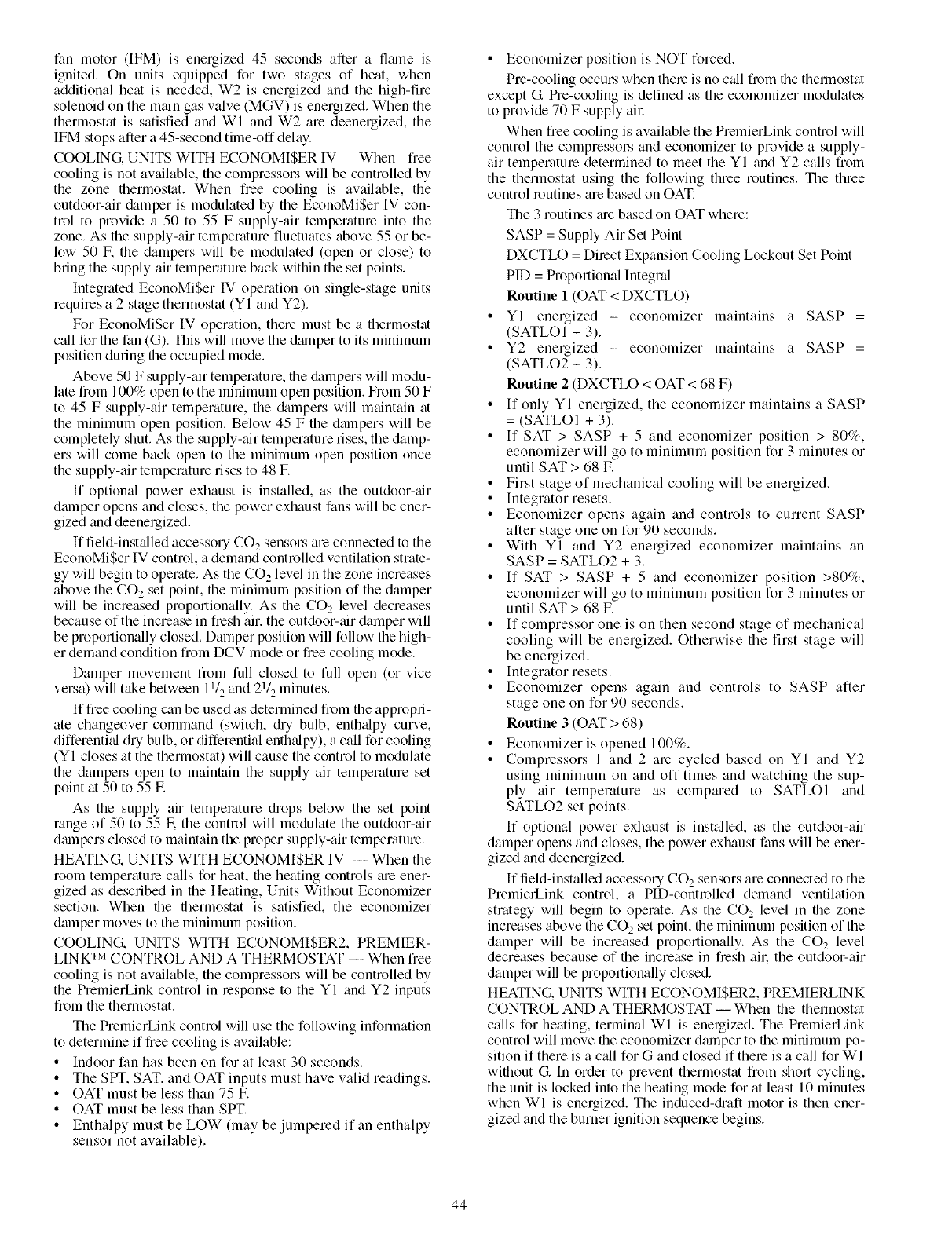
fanmotor(IFM)is energized45secondsariela flalneis
ignited.Onunitsequippedfor twostagesof heat,when
additionalheatisneeded,W2isenergizedandthehigh-fire
solenoidonthemgfingasvalve(MGV)isenergized.Whenthe
thermostatissatisfiedandWI andW2aredeenergized,the
IFMstopsaftera45-secondtime-offdelay.
COOLING. UNITS WITH ECONOMISER IV -- When free
cooling is not available, the compressors will be controlled by
the zone thermostat. When free cooling is available, the
outdoor-air &unper is modulated by tile EconoMiSer IV con-
trol to provide a 50 to 55 F supply-air temperature into the
zone. As the supply-air temperature fluctuates above 55 or be-
low 50 L the dampers will be modulated (open or close) to
bring the supply-air temperature back within the set points.
Integrated EconoMiSer IV operation on single-stage units
requires a 2-stage thermostat (YI and Y2).
For EconoMiSer IV operation, there must be a therlnostat
call for the fan (G). This will move the dmnper to its minimum
position during the occupied mode.
Above 50 F supply-air temperature, the &tmpers will modu-
late from 100% open to the minimum open position. From 50 F
to 45 F supply-air temperature, the &_mpers will maintain at
the minimum open position. Below 45 F the dampers will be
completely shut. As the supply-air temperature rises, the damp-
ers will come back open to the minimum open position once
the supply-air temperature rises to 48 E
If optional power exhaust is installed, as the outdoor-air
damper opens and closes, the power exhaust fans will be ener-
gized and deenergized.
If field-inst_dled accessory CO 2 sensors me connected to the
EconoMi$er IV control, a demand controlled ventilation strate-
gy will begin to operate. As the CO 2 level in the zone increases
above the CO 2 set point, the minimum position of the damper
will be increased proportionally. As the CO2 level decreases
because of the increase in fresh air. the outdoor-air damper will
be proportionally closed. Damper position will follow the high-
er demand condition fiom DCV mode or free cooling mode.
Damper movement from full closed to full open (or vice
versa) will take between 1I/2 and 21/2 minutes.
If free cooling can be used as determined from the appropri-
ate changeover command (switch, @ bulb, enth_dpy curve,
differenti_d dry bulb, or differential enth_dpy), a call for cooling
(YI closes at the thermostat) will cause the control to modulate
the dampers open to maintain the supply air temperature set
point at 50 to 55 E
As the supply air temperature drops below the set point
range of 50 to 55 E the control will modulate the outdoor-tdr
dmnpers closed to maintain the proper supply-air temperature.
HEATING. UNITS WITH ECONOMI$ER IV -- When the
room temperature calls for heat, the heating controls are ener-
gized as described in the Heating, Units Without Economizer
section. When the thermostat is satisfied, the economizer
dmnper moves to the minimum position.
COOLING. UNITS WITH ECONOMI$ER2, PREMIER-
LINK TM CONTROL AND A THERMOSTAT -- When free
cooling is not available, the compressors will be controlled by
the PremierLink control in response to the YI and Y2 inputs
from the thermostat.
The PremierLink control will use the following information
to determine if free cooling is available:
•Indoor fan has been on for at least 30 seconds.
• The SPT, SAT, and OAT inputs must have valid readings.
• OAT must be less than 75 E
• OAT must be less than SPT.
• Enthalpy must be LOW (may be jumpered if an enthalpy
sensor not available).
• Economizer position is NOT forced.
Pro-cooling occurs when there is no call from the therlnostat
except G Pre-cooling is defined as the economizer modulates
to provide 70 F supply all:
When free cooling is available the PremierLink control will
control the compressors and economizer to provide a supply-
air temperature determined to meet the YI and Y2 calls from
the thermostat using the following three routines. The three
control routines are based on OAT.
The 3 routines me based on OAT where:
SASP = Supply Air Set Point
DXCTLO = Direct Expansion Cooling Lockout Set Point
PID = Proportional Integral
Routine 1 (OAT < DXCTLO)
• YI energized - economizer maintains a SASP =
(SATLOI + 3).
• Y2 energized - economizer maintains a SASP =
(SATLO2 + 3).
Routine 2 (DXCTLO < OAT < 68 F)
• If only YI energized, the economizer maintains a SASP
= (SATLOI + 3).
• If SAT > SASP + 5 and economizer position > 80%,
economizer will go to minimum position for 3 minutes or
until SAT > 68 IF.
• First stage of mechanical cooling will be energized.
• Integrator resets.
• Economizer opens again and controls to current SASP
after stage one on for 90 seconds.
• With YI and Y2 energized economizer maintains an
SASP = SATLO2 + 3.
• If SAT > SASP + 5 and economizer position >80%,
economizer will go to minimum position for 3 minutes or
until SAT > 68 IF.
• If compressor one is on then second stage of mechanical
cooling will be energized. Otherwise the first stage will
be energized.
• Integrator resets.
• Economizer opens again and controls to SASP after
stage one on for 90 seconds.
Routine 3 (OAT > 68)
• Economizer is opened 100%.
• Compressors 1 and 2 are cycled based on YI and Y2
using minimum on and off times and watching the sup-
ply air temperature as compared to SATLOI and
SATLO2 set points.
If optional power exhaust is inst:dled, as the outdoor-air
damper opens and closes, the power exhaust fans will be ener-
gized and deenergized.
If field-installed accessory CO 2 sensors are connected to the
PremielLink control, a PID-controlled demand ventilation
strategy will begin to operate. As the CO2 level in the zone
increases above the CO2 set point, the minimum position of the
damper will be increased proportionally. As the CO 2 level
decreases because of the increase in fresh ail: the outdoor-air
damper will be proportionally closed.
HEATING. UNITS WITH ECONOMISER2, PREMIERLINK
CONTROL AND A THERMOSTAT -- When the thermostat
calls for heating, terminal WI is energized. The PremierLink
control will move the economizer damper to the minimum po-
sition if there is a c_dl for G and closed if there is a call for WI
without G. In order to prevent thermostat from short cycling,
the unit is locked into the heating mode for at least 10 minutes
when WI is energized. The induced-&aft motor is then ener-
gized and the burner ignition sequence begins.
44
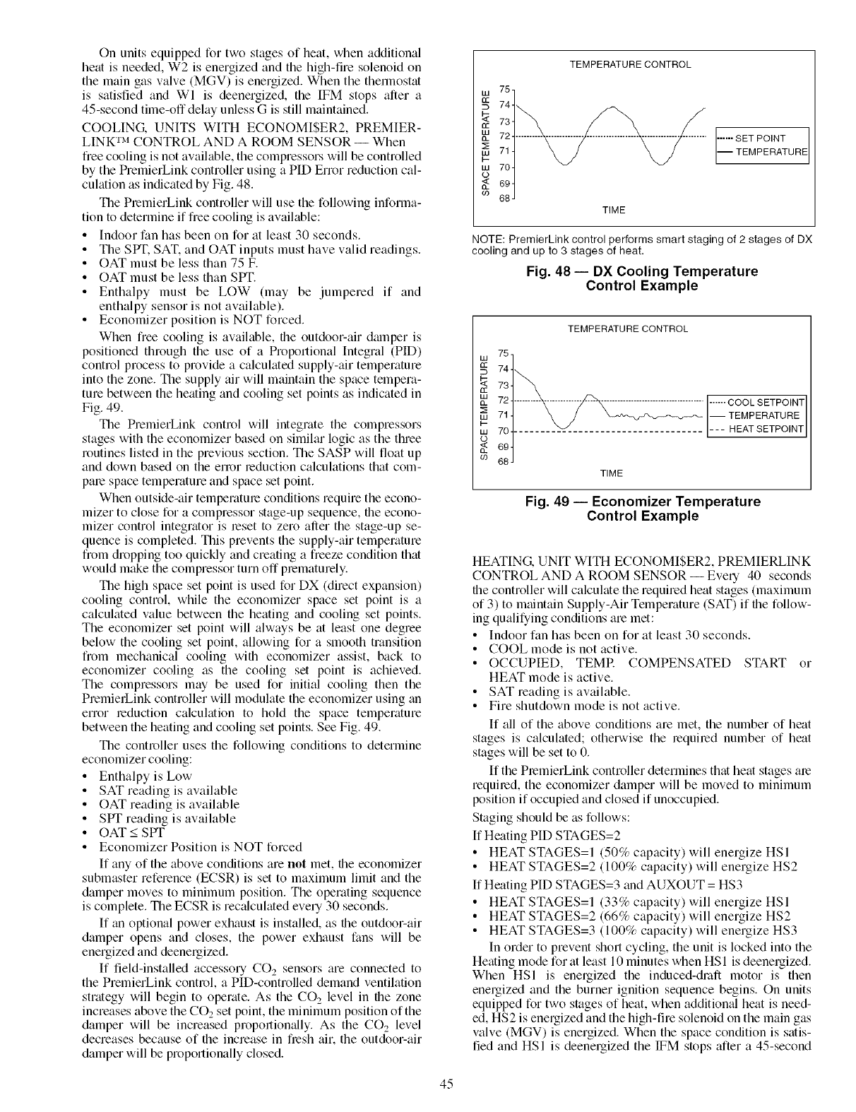
Onunitsequippedfortwostagesofheat,whenadditional
heatisneeded,W2isenergizedandthehigh-firesolenoidon
themaingasvalve(MGV)isenergized.Whenthethennostat
is satisfiedandWI is deenergized,the[FM stopsaftera
45-secondtime-offdelayunlessGisstillmaintained.
COOLING. UNITS WITH ECONOMI$ER2, PREMIER-
LINK TM CONTROL AND A ROOM SENSOR -- When
free cooling is not available, the compressors will be controlled
by the PremierLink controller using a PIE) Error reduction cal-
culation as indicated by Fig. 48.
The PremierLink controller will use the following informa-
tion to determine if free cooling is available:
• Indoor fan has been on for at least 30 seconds.
• The SPT. SAT. and OAT inputs must have valid readings.
• OAT must be less than 75 F.
• OAT must be less than SPT.
• Enthalpy must be LOW (may be jumpered if and
enthalpy sensor is not available).
• Economizer position is NOT forced.
When free cooling is available, the outdoor-air dmnper is
positioned through the use of a Proportional Integral (PID)
control process to provide a calculated supply-air temperature
into the zone. The supply air will maintain the space tempera-
ture between the heating and cooling set points as indicated in
Fig. 49.
The PremierLink control will integrate the compressors
stages with the economizer based on similar logic as the three
routines listed in the previous section. The SASP will float up
and down based on the error reduction calculations that com-
pare space temperature and space set point.
When outside-air temperature conditions require the econo-
mizer to close for a compressor stage-up sequence, the econo-
mizer control integrator is reset to zero aller the stage-up se-
quence is completed. This prevents the supply-air temperature
from dropping too quickly and creating a freeze condition that
would make the compressor turn off prematurely.
The high space set point is used for DX (direct expansion)
cooling control, while the economizer space set point is a
calculated value between the heating and cooling set points.
The economizer set point will always be at least one degree
below the cooling set point, allowing for a smooth transition
from mechanical cooling with economizer assist, back to
economizer cooling as the cooling set point is achieved.
The compressors may be used for initial cooling then the
PremierLink controller will modulate the economizer using an
error reduction calculation to hold the space temperature
between the heating and cooling set points. See Fig. 49.
The controller uses the following conditions to determine
economizer cooling:
• Enthalpy is Low
• SAT reading is available
• OAT reading is available
• SPT reading is available
• OAT < SPT
• Economizer Position is NOT forced
If any of the above conditions are not met, the economizer
submaster reference (ECSR) is set to maximum limit and the
damper moves to minimum position. The operating sequence
is complete. The ECSR is rec;dculated every 30 seconds.
If an optional power exhaust is installed, as the outdoor-air
damper opens and closes, the power exhaust fans will be
energized and deenergized.
If field-installed accessory CO 2sensors are connected to
the PremierLink control, a PID-controlled demand ventilation
strategy will begin to operate. As the CO 2 level in the zone
increases above the CO2 set point, the minimum position of the
damper will be increased proportionally. As the CO 2 level
decreases because of the increase in flesh air. the outdoor-air
damper will be proportionally closed.
TEMPERATURE CONTROL
LU 75
74
_: 73
el: 72
,,=,71
b-
tu 70
o69
09 68
TIME
...... SET POINT
-- TEMPERATURE
NOTE: PremierLink control performs smart staging of 2 stages of DX
cooling and up to 3 stages of heat,
Fig. 48 i DX Cooling Temperature
Control Example
TEMPERATURE CONTROL
75
741_ "
73
72 ......... _ .................................... ------COOL SETPOINT
71 ] _ // _ -- TEMPERATURE
704 ........ _ .......................... --- HEAT SETPOINT
J
69
68
TIME
Fig. 49 -- Economizer Temperature
Control Example
HEATING. UNIT WITH ECONOMISER2, PREMIERLINK
CONTROL AND A ROOM SENSOR -- Every 40 seconds
the controller will calculate the required heat stages (maximum
of 3) to mtfintain Supply-Air Temperature (SAT) if the follow-
ing qualifying conditions are met:
• Indoor fan has been on for at least 30 seconds.
• COOL mode is not active.
• OCCUPIED, TEMR COMPENSATED START or
HEAT mode is active.
•SAT reading is available.
• Fire shutdown mode is not active.
If all of the above conditions are met, the number of heat
stages is calculated; otherwise the required number of heat
stages will be set to 0.
If the PremierLink controller determines that heat stages are
required, the economizer damper will be moved to minimum
position if occupied and closed if unoccupied.
Staging should be as follows:
If Heating PIE) STAGES=2
• HEATSTAGES=I (50% capacity) will energize HSI
• HEAT STAGES=2 (100% capacity) will energize HS2
If Heating PID STAGES=3 and AUXOUT = HS3
• HEAT STAGES=I (33% capacity) will energize HSI
• HEAT STAGES=2 (66% capacity) will energize HS2
• HEAT STAGES=3 (100% capacity) will energize HS3
In order to prevent short cycling, the unit is locked into the
Heating mode forat least 10 minutes when HSI is deenergized.
When HSI is energized the induced-draft motor is then
energized and the burner ignition sequence begins. On units
equipped for two stages of heat, when additiomfl heat is need-
ed, HS2 is energized and the high-fire solenoid on the main gas
valve (MGV) is energized. When the space condition is satis-
tied and HSI is deenergized the IFM stops after a 45-second
45
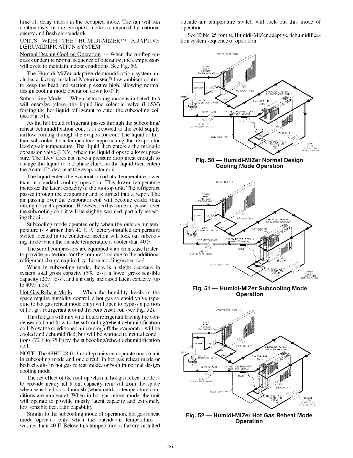
time-offdelayunlessintheoccupiedmode.Tilefanwillrun
continuouslyintheoccupiedmodeasrequiredbynational
energyandfreshairstandards.
UNITS WITH THE HUMIDI-MIZERTM ADAPTIVE
DEHUMIDIFICATION SYSTEM
Normal Design Cooling Operation -- When the rooftop op-
erates under the normal sequence of operation, the compressol_
will cycle to maintain indoor conditions. See Fig. 50.
The Humidi-MiZer adaptive dehumidification system in-
cludes a factory installed Motormastel® low ambient control
to keep the head and suction pressure high, tallowing normal
design cooling mode operation down to 0 ° IF.
Subcooling Mode -- When subcooling mode is initiated, this
will energize (close) the liquid line solenoid valve (LLSV)
forcing the hot liquid refrigerant to enter the subcooling coil
(see Fig. 51 ).
As the hot liquid refrigerant passes through the subcoolinJ
reheat dehumidification coil, it is exposed to the cold supply
airflow coming fllrough the evaporator coil. The liquid is fur-
ther subcooled to a temperature approaching the evaporator
leaving-air temperature. The liquid then entel_ a thermostatic
expansion valve (TXV) where the liquid drops to a lower pres-
sure. The TXV does not have a pressure drop great enough to
change the liquid to a 2-phase fluid, so the liquid then enters
the Acutrol TM device tit the evaporator coil.
The liquid enters the evaporator coil tit a temperature lower
than in standard cooling operation. This lower temperature
increases the latent capacity of the rooftop unit. The refrigerant
passes through the evaporator and is turned into a vapor. The
air passing over the evaporator coil will become colder than
during normal operation. Howevel: as this same air passes over
the subcooling coil, it will be slightly warmed, pmtially reheat-
ing the ail:
Subcooling mode operates only when the outside-air tem-
perature is wmmer than 40 E A factory-installed temperature
switch located in the condenser section will lock out subcool-
ing mode when the outside temperature is cooler than 40 E
The scroll compressors are equipped with crankcase heaters
to provide protection for the compressors due to the additiomd
refrigerant charge required by the subcoolinJleheat coil.
When in subcooling mode, there is a slight decrease in
system total gross capacity (5% less), a lower gross sensible
capacity (20% less), and a greatly increased latent capacity (up
to 40% more).
Hot Gas Reheat Mode -- When the humidity levels in the
space require humidity control, a hot gas solenoid valve (spe-
cific to hot gas leheat mode only) will open to bypass a portion
of hot gas refrigerant around the condenser coil (see Fig. 52).
This hot gas will mix wifll liquid refrigerant leaving the con-
denser coil and flow to the subcooling/reheat dehumidification
coil. Now the conditioned air coming off the evaporator will be
cooled and dehumidified, but will be wmmed to neutral condi-
tions (72 F to 75 F) by the subcooling/reheat dehumidification
coil.
NOTE: The 48HJ008-014 rooftop units can operate one circuit
in subcooling mode and one circuit in hot gas reheat mode or
both circuits in hot gas reheat mode, or both in normal design
cooling mode.
The net effect of the rooftop when in hot gas reheat mode is
to provide nearly tdl latent capacity removal from the space
when sensible loads diminish (when outdoor temperature con-
ditions are moderate). When in hot gas reheat mode, the unit
will operate to provide mostly latent capacity and extremely
low sensible heat ratio capability.
Similar to the subcooling mode of operation, hot gas reheat
mode operates only when the outside-air temperature is
warmer than 40 E Below this temperature, a factory-installed
outside air temperature switch will lock out this mode of
operation.
See Table 25 for file Humidi-MiZer a&tptive dehumidifica-
tion system sequence of operation.
Fig. 50 -- Humidi-MiZer Normal Design
Cooling Mode Operation
/'_ CLOSE_)
VALVE LLSV
_ulB [NE
SO .3_ VAVE_
Fig. 51 -- Humidi-MiZer Subcooling Mode
Operation
L_5 /
Fig. 52 -- Humidi-MiZer Hot Gas Reheat Mode
Operation
46
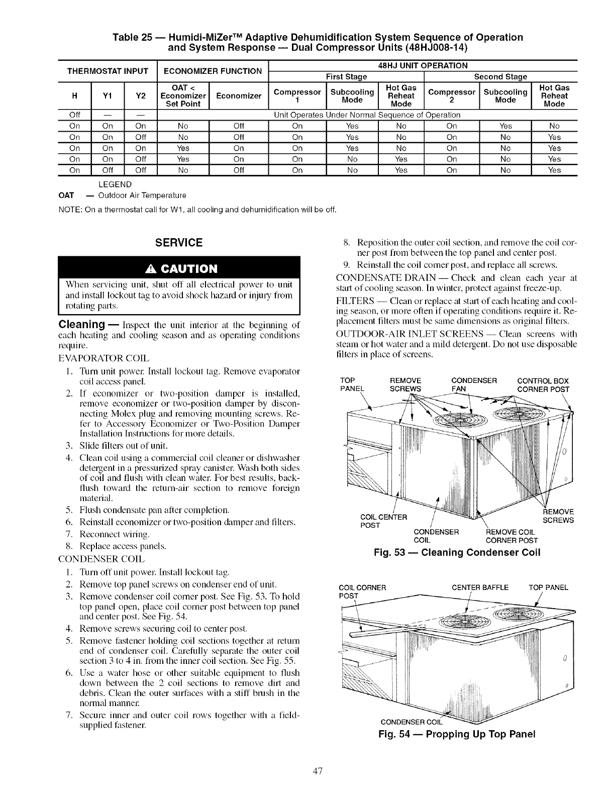
Table 25 -- Humidi-MiZer TM Adaptive Dehumidification System Sequence of Operation
and System Response- Dual Compressor Units (48HJ008-14)
THERMOSTAT INPUT ECONOMIZER FUNCTION
Off
On On
On On
On On
On On
On Off
LEGEND
48HJ UNIT OPERATION
First Stage Second Stage
Hot Gas
Subcooling Reheat Compressor Subcooling
Mode
OAT < Hot Gas
H Y1 Y2 Economizer Economizer Compressor Reheat
Set Point 1 Mode Mode 2 Mode
-- Unit Operates Under Normal Sequence of Operation
On No Off On Yes No On Yes No
Off No Off On Yes No On No Yes
On Yes On On Yes No On No Yes
Off Yes On On No Yes On No Yes
Off No Off On No Yes On No Yes
OAT -- Outdoor Air Temperature
NOTE: On a thermostat call for W1, all cooling and dehumidification will be off.
SERVICE
When servicing unit, shut off all electrical power to unit
and install lockout tag to avoid shock hazard or injury fiom
rotating p_uts.
Cleaning --Inspect the unit interior at the beginning of
each heating and cooling season and as operating conditions
require.
EVAPORATOR COIL
1. Turn unit powel: Install lockout tag. Remove evaporator
coil access panel.
2. If economizer or two-position damper is installed,
remove economizer or two-position damper by discon-
necting Molex plug and removing mounting screws. Re-
fer to Accesso UEconomizer or Two-Position Damper
Installation Instructions for morn details.
3. Slide flltel.sout of unit.
4. Clean coil using a commercial coil cleaner or dishwasher
detergent in a pressurized spray canistel: Wash both sides
of coil and flush with clean watel: For best results, back-
flush toward the return-air section to remove foreign
material.
5. Flush condensate pan after completion.
6. Reinstall economizer or two-position &_mper and filters.
7. Reconnect wiring.
8. Replace access panels.
CONDENSER COIL
1. Turn off unit powel: Install lockout tag.
2. Remove top panel screws on condenser end of unit.
3. Remove condenser coil corner post. See Fig. 53. To hold
top panel open, place coil corner post between top panel
and center post. See Fig. 54.
4. Remove screws securing coil to center post.
5. Remove fastener holding coil sections together at return
end of condenser coil. Carefully separate the outer coil
section 3 to 4 in. from the inner coil section. See Fig. 55.
6. Use a water hose or other suitable equipment to flush
down between the 2 coil sections to remove dirt and
debris. Clean the outer surfaces with a stiff brush in the
normal mannel:
7. Secure inner and outer coil rows together with a field-
supplied fastenel:
8. Reposition the outer coil section, and remove the coil cor-
ner post from between the top panel and center post.
9. Reinstall the coil comer post, and replace all screws.
CONDENSATE DRAIN- Check and clean each year at
start of cooling season. In winter, protect against freeze-up.
FILTERS -- Clean or replace at stm-tof each heating and cool-
ing season, or more often if operating conditions require it. Re-
placement filters must be same dimensions as original filters.
OUTDOOR-AIR INLET SCREENS -- Cle;m screens with
steam or hot water and a mild detergent. Do not use disposable
filters in place of screens.
TOP REMOVE CONDENSER CONTROLBOX
PANEL SCREWS FAN CORNERPOST
\
COIL CENTER
POST CONDENSER REMOVE COIL
COIL CORNER POST
Fig. 53 -- Cleaning Condenser Coil
REMOVE
SCREWS
COILCORNER CENTER BAFFLE
POST
TOP PANEL
CONDENSER COIL
Fig. 54 -- Propping Up Top Panel
47
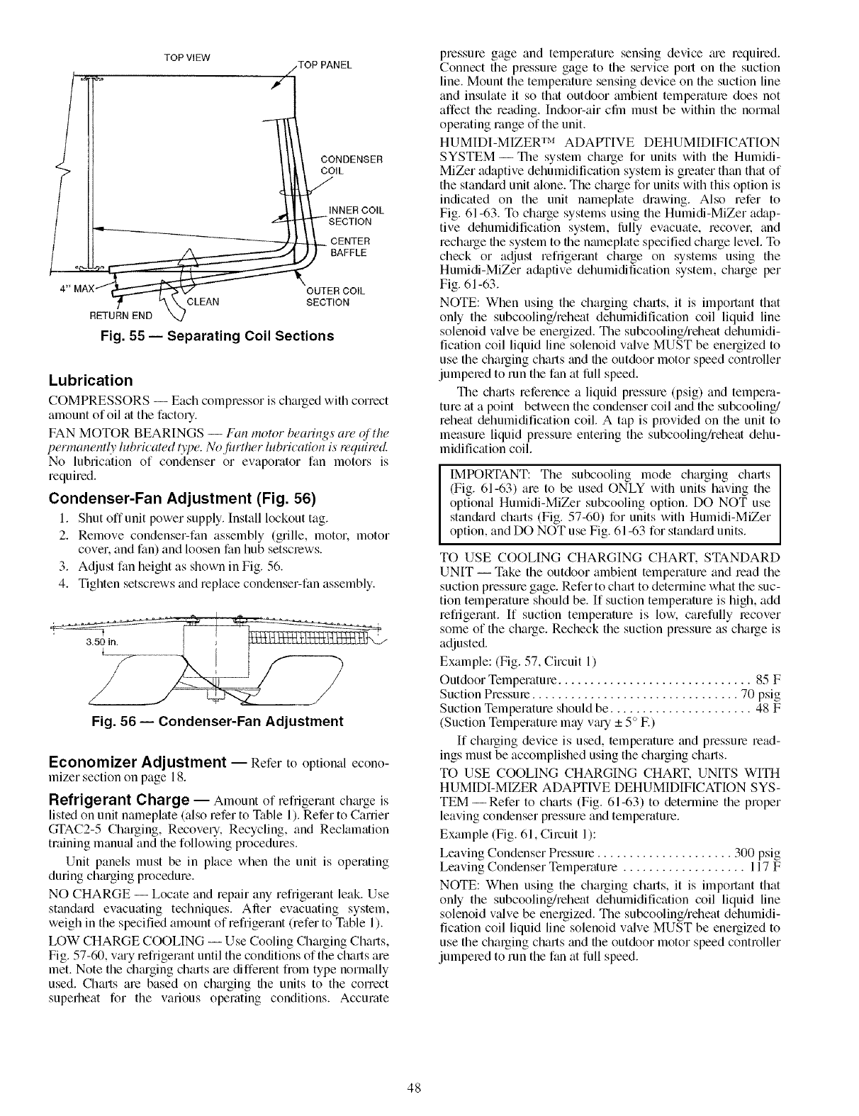
TOP VIEW
TOP PANEL
CONDENSER
(,L
II .,.I I \ L.- INNER COIL
[ t___ __I"_l SECTION
[1 _ CENTER
..--LL_ _) BAFFLE
4'_OUTER COIL
/, \CLEAN SECTION
RETURN END
Fig. 55 -- Separating Coil Sections
Lubrication
COMPRESSORS -- Each compressor is charged with correct
amount ofoil at the factory.
FAN MOTOR BEARINGS -- Fan motor bearings am of the
permanen@ lubHcawd type. No /_u_ther lubrication is wquiwd
No lubrication of condenser or evaporator fan motors is
required.
Condenser-Fan Adjustment (Fig. 56)
I. Shut off unit power supply. Install lockout tag.
2. Remove condenser-fan assembly (grille, motor, motor
cover, and fan) and loosen fan hub setscrews.
3. Adjust fan height as shown in Fig. 56.
4. Tighten setscrews and replace condenser-fan assembly.
3.50 in. __LL_LLLLLLLLLLLLLLLLLU \J
z /
Fig. 56 -- Condenser-Fan Adjustment
Economizer Adjustment -- Refer to optional econo-
mizer section on page 18.
Refrigerant Charge -- Amount of refrigerant chmge is
listed on unit nameplate (also refer to Table 1). Refer to Carrier
GI'AC2-5 Charging, Recovery. Recycling, and Reclamation
training manu;fl and the following procedures.
Unit panels must be in place when the unit is operating
during chm'ging procedure.
NO CHARGE -- Locate and repair any refrigerant leak. Use
standard evacuating techniques. Aller evacuating system,
weigh in the specified amount of refrigerant (refer to Table 1).
LOW CHARGE COOLING -- Use Cooling Charging Charts,
Fig. 57-60, vmy refrigerant until the conditions of the charts are
met. Note the chmging charts me different from type normally
used. Charts are based on charging the units to the correct
superheat for the various operating conditions. Accurate
pressure gage and temperature sensing device ;ue required.
Connect the pressure gage to the service port on the suction
line. Mount the temperature sensing device on the suction line
and insulate it so that outdoor ambient temperature does not
affect the reading. Indoor-air cfln must be within the normal
operating range of the unit.
HUMIDI-MIZER TM ADAPTIVE DEHUMIDIFICATION
SYSTEM- The system charge for units with the Humidi-
MiZer adaptive dehumidification system is greater than that of
the standard unit alone. The charge for units with this option is
indicated on the unit nameplate drawing. Also refer to
Fig. 61-63. To chmge systems using the Humidi-MiZer a&tp-
tive dehumidification system, lhlly evacuate, recovel: and
rechmge the system to the nmneplate specified charge level. To
check or adjust refrigerant charge on systems using the
Humidi-MiZer a&tptive dehumidification system, charge per
Fig. 61-63.
NOTE: When using the charging charts, it is important that
only the subcooling/reheat dehumidification coil liquid line
solenoid valve be energized. The subcooling/reheat dehumidi-
fication coil liquid line solenoid valve MUST be energized to
use the charging charts and the outdoor motor speed controller
jumpered to run the fan at full speed.
The ch;uts reference a liquid pressure (psig) and tempera-
ture at a point between the condenser coil and the subcooling/
reheat dehumidification coil. A tap is provided on the unit to
measure liquid pressure entering the subcooling/reheat dehu-
midification coil.
IMPORTANT: The subcooling mode charging charts
(Fig. 61-63) am to be used ONLY with units having the
optional Humidi-MiZer subcooling option. DO NOT use
standard chmls (Fig. 57-60) for units with Humidi-MiZer
option, and DO NOT use Fig. 61-63 for standard units.
TO USE COOLING CHARGING CHART. STANDARD
UNIT -- Take the outdoor ambient temperature and read the
suction pressure gage. Refer to chart to determine what the suc-
tion temperature should be. If suction temperature is high, add
refrigerant. If suction temperature is low. carefully recover
some of the charge. Recheck the suction pressure as charge is
adjusted.
Example: (Fig. 57, Circuit 1)
Outdoor Temperature .............................. 85 F
Suction Pressure ................................ 70 psig
Suction Temperature should be ...................... 48 F
(Suction Temperature may v_u'y _+5 ° E)
If charging device is used, temperature and pressure read-
ings must be accomplished using the charging charts.
TO USE COOLING CHARGING CHART. UNITS WITH
HUMIDI-MIZER ADAPTIVE DEHUMIDIFICATION SYS-
TEM--Refer to charts (Fig. 61-63) to determine the proper
leaving condenser pressure and temperature.
Example (Fig. 61, Circuit 1):
Leaving Condenser Pressure ..................... 300 psig
Leaving Condenser Temperature ................... 117 F
NOTE: When using the charging charts, it is important that
only the subcooling/reheat dehumidification coil liquid line
solenoid valve be energized. The subcooling/reheat dehumidi-
fication coil liquid line solenoid valve MUST be energized to
use the charging charts and the outdoor motor speed controller
jumpered to run the fan at full speed.
48
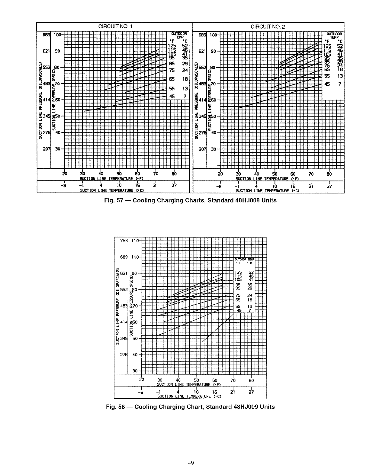
20?
iiii
::i:
::!!
iiii
!!!!
llll
45/,JCTION LINE TEMPERATURE
I
5_JCTION LINE TEMPERATURE
C° F)
!I
16 21
CoC)
CIRCUIT NO. 2
SUCTION LINE TEMPERATURE(-F)
i]I I !
-6 -1 410 16
SUCTION LINE TERPERkTU(_ CoG)
Fig. 57 -- Cooling Charging Charts, Standard 48HJ008 Units
!
21
75E
68;
b_ 621
o
CL
J55;
4B:
IiJ
_.z41z
J
z
Q
34E
m
27E
30 40 50 60 70 BO
SUCTION LINE TEMPERATURE ('F)
I IIIIJ I
-6 -1 4 10 16 21 27
SUCTION LINE TEMPERATURE('C)
Fig. 58 -- Cooling Charging Chart, Standard 48HJ009 Units
49
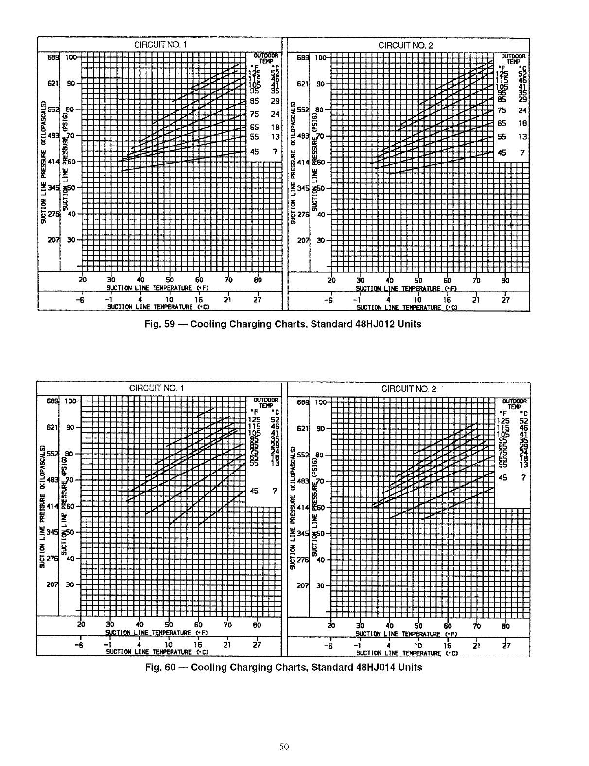
CIRCUITNO.1
I I I I
10 16 21 27-1 4
SUCTION LINE TEHPERATURE('C]
9O
4O
3O
I
-6
CIRCUIT NO. 2
??!? ???!
iiii iiii
:::: ::::
iiii iiii
::;: iii_
iiiii
i I I_ I L..,I-.-F
!! !? ! !_-.r
:::: ::::
!iiii !!ii
i ........
0,0
-1 4 10 16
5UCTI_ LI_TEHPERATURE('_
I
21
Fig. 59 -- Cooling Charging Charts, Standard 48HJ012 Units
I
27
6891 10C
6211 90
u_
•-'4e3130
i=_
I
-6
2071 30
CIRCUIT NO. 1
!!!!
i i.,F-]-
;;1!
iiii
iiii
III[
III:
!!!!
i!ii
70 80
SUCTION LINE TENPERATURE ('F) _dCTll
t I I I I !
-1 4 10 16 21 27 -6 -1 4
SUCTION LINE TE,VPERATURE('C) SUCTION LINE
CIRCUIT NO, 2
IIIII
_!?!?
!!!!!
: : : "=
;: : ="
: : : ="
:! ! !
bg
10 16
TEHPERATUNE('C)
Fig. 60 -- Cooling Charging Charts, Standard 48HJ014 Units
5O
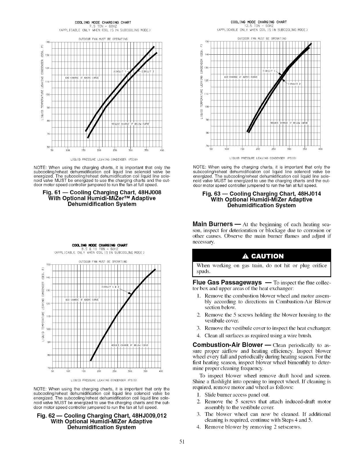
COOLING MODE CHARGING CHART
7,B ]ON - BOHZ
(APPLICABLE ONLY WHEN COIL IS IN SUBCOOLING MODE)
140
2
9 _so
z
o
He
ioc
i_- 9c
_c
?o
so
OUTDOOR FAN MUST BE OPERATING
HHHHHHHIq
HHHHHHIq '
HHHHIeM HH
i00 150 2oo 25o soo 35o 40o
lIQUID PRESSURE AV!NG CONI]INSER (PS8)
NOTE: When using the charging charts, it is important that only the
subcooling/reheat dehumidification coil liquid line solenoid valve be
energized. The subcooling/reheat dehumidification coil liquid line sole-
noid valve MUST be energized to use the charging charts and the out-
door motor speed controller jumpered to run the fan at full speed.
Fig. 61 -- Cooling Charging Chart, 48HJ008
With Optional Humidi-MiZer TM Adaptive
Dehumidification System
COOLING MODE CHARGING CHART
!2,B 70N BOHZ
(APPI !BAB } ONLY WIEN ¢0!I 15 ]N UBCOOLING MBDE)
9
$
o
w
OUTDOOR FAN MU51 BE OPERAIING
13o
_2o
I_O
IOC9_
too _5o 2oo 25o 3oo sso
LIQUID PRESSURE LEAVING CONDENSER (PSIG)
NOTE: When using the charging charts, it is important that only the
subcooling/reheat dehumidification coil liquid line solenoid valve be
energized. The subcooling/reheat dehumidification coil liquid line sole-
noid valve MUST be energized to use the charging charts and the out-
door motor speed controller jumpered to run the fan at full speed.
Fig. 63 -- Cooling Charging Chart, 48HJ014
With Optional Humidi-MiZer Adaptive
Dehumidification System
COOLIN6 ROOE CI_II_ CflART
8,5 F. 10 F0N 60HZ
(APPI CAIIL ONLY WHN COIL 15 IN BUBCO01 ING MOB )
OUTDOOR FAN MUST BE OPERATING
IIQUII) PR 5iURE lEAVING CONI)ENSVR (PS!G}
NOTE: When using the charging charts, it is important that only the
subcooling/reheat dehumidification coil liquid line solenoid valve be
energized. The subcooling/reheat dehumidification coil liquid line sole-
noid valve MUST be energized to use the charging charts and the out-
door motor speed controller jumpered to run the fan at full speed.
Fig. 62 -- Cooling Charging Chart, 48HJ009,012
With Optional Humidi-MiZer Adaptive
Dehumidification System
Main Burners -- At tile beginning of each heating sea-
son, inspect for deterioration or blockage due to corrosion or
other causes. Observe the main burner flames and adjust if
necessary.
When working on gas train, do not hit or plug orifice
spuds.
Flue Gas Passageways -- To inspect the flue collec-
tor box and upper meas of the heat exchanger:
1. Remove the combustion blower wheel and motor assem-
bly according to directions in Combustion-Air Blower
section below.
2. Remove the 5 screws holding the blower housing to the
vestibule covet
3. Remove the vestibule cover to inspect the heat exchangec
4. Clean all surfaces as required using a wire brush.
Combustion-Air Blower-- Clean periodically to as-
sure proper airflow and heating efficiency. Inspect blower
wheel every fall and periodic;ally during heating season. For the
first heating season, inspect blower wheel bimonthly to deter-
mine proper cleaning frequency.
To inspect blower wheel remove diaft hood and screen.
Shine a flashlight into opening to inspect wheel. If cleaning is
required, remove motor and wheel as follows:
1. Slide burner access panel out.
2. Remove the 5 screws that attach induced-diaft motor
assembly to the vestibule covet
3. The blower wheel can now be cleaned. If additional
cleaning is required, continue with Steps 4 and 5.
4. Remove blower by removing 2 setscrews.
51
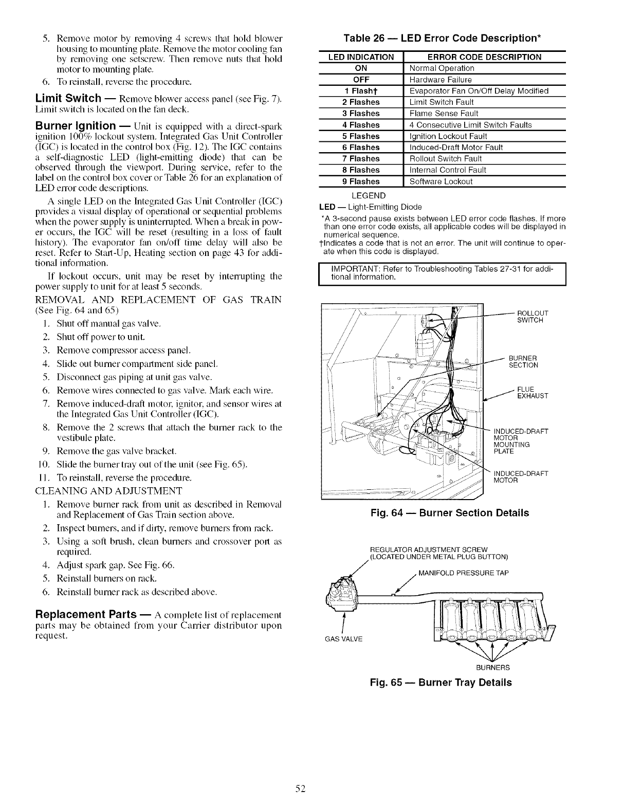
5. Removemotorbyremoving4screwsthatholdblower
housingtomountingplate.Removethemotorcoolingfan
byremovingonesetscrew.Thenremovenutsthathold
motortomountingplate.
6. Toreinstall,reversetheprocedure.
Limit Switch -- Remove blower access panel (see Fig. 7).
Limit switch is located on the fan deck.
Burner Ignition -- Unit is equipped with a direct-spark
ignition 100% lockout system. Integrated Gas Unit Controller
(IGC) is located in the control box (Fig. 12). The [GC contains
a self-diagnostic LED (light-emitting diode) that can be
observed through the viewport. During service, refer to the
label on the control box cover or Table 26 for an explanation of
LED error code descriptions.
A single LED on the Integrated Gas Unit Controller (IGC)
provides a visual display of opemtiomd or sequential problems
when the power supply is uninterrupted. When a break in pow-
er occurs, the IGC will be reset (resulting in a loss of fault
history). The ew_porator fan on/off time delay will also be
reset. Refer to Start-Up, Heating section on page 43 for addi-
tional information.
If lockout occuLs, unit may be reset by interrupting the
power supply to unit for at least 5 seconds.
REMOVAL AND REPLACEMENT OF GAS TRAIN
(See Fig. 64 and 65)
1. Shut offmanual gas valve.
2. Shut offpowerto unit.
3. Remove compressor access panel.
4. Slide out burner compartment side panel.
5. Disconnect gas piping at unit gas valve.
6. Remove wires connected to gas valve. MaN each wire.
7. Remove induced-draft motol: ignitor, and sensor wires at
the Integrated Gas Unit Controller (IGC).
8. Remove the 2 screws that attach the burner rack to the
vestibule plate.
9. Remove the gas valve bracket.
10. Slide the burner tray out of the unit (see Fig. 65).
11. To reinstall, reverse the procedure.
CLEANING AND ADJUSTMENT
1. Remove burner rack from unit as described in Removed
and Replacement of Gas Train section above.
2. Inspect burners, and if dirty, remove burners from rock.
3. Using a soft brush, clean burners and crossover port as
required.
4. Adjust spmk gap. See Fig. 66.
5. Reinstall burners on rock.
6. Reinstall burner rack as described above.
Replacement Parts -- A complete list of replacement
parts may be obtained from your Carrier distributor upon
request.
Table 26 -- LED Error Code Description*
LED INDICATION
ON
OFF
1Flasht
2 Flashes
3 Flashes
4 Flashes
5 Flashes
6 Flashes
7 Flashes
8 Flashes
9 Flashes
LEGEND
ERROR CODE DESCRIPTION
Normal Operation
Hardware Failure
Evaporator Fan On/Off Delay Modified
Limit Switch Fault
Flame Sense Fault
4 Consecutive Limit Switch Faults
Ignition Lockout Fault
Induced-Draft Motor Fault
Rollout Switch Fault
Internal Control Fault
Software Lockout
LED -- Light-Emitting Diode
*A 3-second pause exists between LED error code flashes. If more
than one error code exists, all applicable codes will be displayed in
numerical sequence,
lqndicates a code that is not an error.The unit will continue to oper-
ate when this code is displayed.
I IMPORTANT:Refer to Troubleshooting Tables27-31 for addi- I
tional information, I
SWITCH
BURNER
SECTION
FLUE
EXHAUST
INDUCED-DRAFT
MOTOR
MOUNTING
PLATE
INDUCED-DRAFT
MOTOR
Fig. 64 -- Burner Section Details
REGULATOR ADJUSTMENT SCREW
(LOCATED UNDER METAL PLUG BUTTON)
. MANIFOLD PRESSURE TAP
GAS VALVE
BURNERS
Fig. 65 -- Burner Tray Details
52
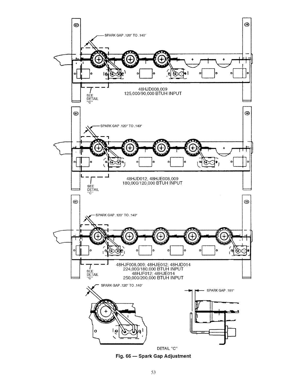
SEE
DETAIL
48HJ D008,009
125,000/90,000 BTUH INPUT
SEE
DETAIL
/48HJD012, 48HJE008,009
180,000/120,000 BTUH INPUT
48HJF008,009; 48HJE012; 48HJD014
224,000/180,000 BTUH INPUT
48HJ F012; 48HJE014
250,000/200,000 BTUH INPUT
SPARK GAP,120"TO ,140"
_K GAP .181"
!!-,cC:
DETAIL "C"
Fig. 66 -- Spark Gap Adjustment
53
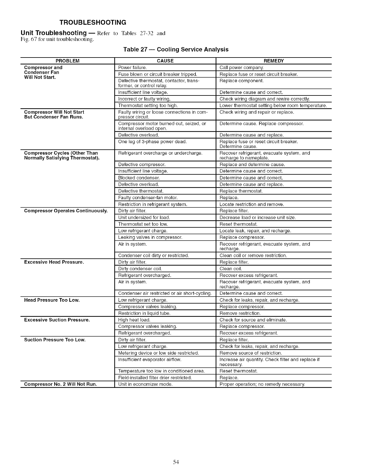
TROUBLESHOOTING
Unit Troubleshooting- Refer to Tables 27-32 and
Fig. 67 for unit troubleshooting.
Table 27 -- Cooling Service Analysis
PROBLEM
Compressorand
CondenserFan
Will NotStart.
Compressor Will Not Start
But Condenser Fan Runs.
Compressor Cycles (Other Than
Normally Satisfying Thermostat).
Compressor Operates Continuously.
Excessive Head Pressure.
Head Pressure Too Low.
Excessive Suction Pressure.
Suction Pressure Too Low.
Compressor No. 2 Will Not Run.
CAUSE
Power failure.
Fuse blown or circuit breaker tripped.
Defective thermostat, contactor, trans-
former, or control relay.
Insufficient line voltage.
Incorrect or faulty wiring.
Thermostat setting too high.
Faulty wiring or loose connections in com-
pressor circuit.
Compressor motor burned out, seized, or
internal overload open.
Defective overload.
One leg of 3-phase power dead.
Refrigerant overcharge or undercharge.
Defective compressor.
Insufficient line voltage.
Blocked condenser.
Defective overload.
Defective thermostat.
Faulty condenser-fan motor.
Restriction in refrigerant system.
Dirty air filter.
Unit undersized for load.
Thermostat set too low.
Low refrigerant charge.
Leaking valves in compressor.
Air in system.
Condenser coil dirty or restricted.
Dirty air filter.
Dirty condenser coil.
Refrigerant overcharged.
Air in system.
Condenser air restricted or air short-cycling.
Low refrigerant charge.
Compressor valves leaking.
Restriction in liquid tube.
High heat load.
Compressor valves leaking.
Refrigerant overcharged.
Dirty air filter.
Low refrigerant charge.
Metering device or low side restricted.
Insufficient evaporator airflow.
Temperature too low in conditioned area.
Field-installed filter drier restricted.
Unit in economizer mode.
REMEDY
Call power company.
Replace fuse or reset circuit breaker.
Replace component.
Determine cause and correct.
Check wiring diagram and rewire correctly.
Lower thermostat setting below room temperature.
Check wiring and repair or replace.
Determine cause. Replace compressor.
Determine cause and replace.
Replace fuse or reset circuit breaker.
Determine cause.
Recover refrigerant, evacuate system, and
recharge to nameplate.
Replace and determine cause.
Determine cause and correct.
Determine cause and correct.
Determine cause and replace.
Replace thermostat.
Replace.
Locate restriction and remove.
Replace filter.
Decrease load or increase unit size.
Reset thermostat.
Locate leak, repair, and recharge.
Replace compressor.
Recover refrigerant, evacuate system, and
recharge.
Clean coil or remove restriction.
Replace filter.
Clean coil.
Recover excess refrigerant.
Recover refrigerant, evacuate system, and
recharge.
Determine cause and correct.
Check for leaks, repair, and recharge.
Replace compressor.
Remove restriction.
Check for source and eliminate.
Replace compressor.
Recover excess refrigerant.
Replace filter.
Check for leaks, repair, and recharge.
Remove source of restriction.
Increase air quantity. Check filter and replace if
necessary.
Reset thermostat.
Replace.
Proper operation; no remedy necessary.
54
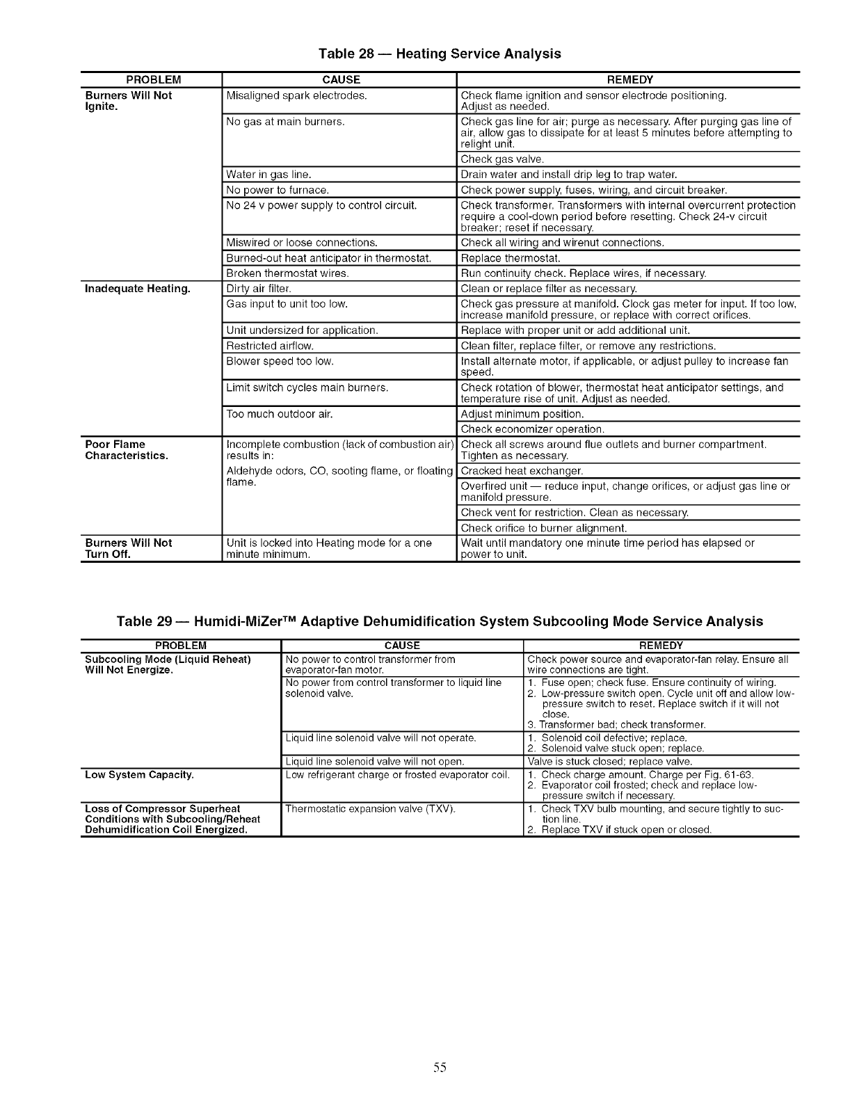
Table 28 -- Heating Service Analysis
PROBLEM CAUSE
Burners Will Not Misaligned spark electrodes.
Ignite.
No gas at main burners.
Water in gas line.
No power to furnace.
No 24 v power supply to control circuit.
Miswired or loose connections.
Burned-out heat anticipator in thermostat.
Broken thermostat wires.
Inadequate Heating, Dirty air filter.
Gas input to unit too low.
Unit undersized for application.
Restricted airflow.
Blower speed too low.
Limit switch cycles main burners.
Too much outdoor air.
Poor Flame
Characteristics.
Burners Will Not
Turn Off.
Incomplete combustion (lack of combustion air',
results in:
Aldehyde odors, CO, sooting flame, or floating
flame.
Unit is locked into Heating mode for a one
minute minimum.
REMEDY
Check flame ignition and sensor electrode positioning.
Adjust as needed.
Check gas line for air; purge as necessary. After purging gas line of
air, allow gas to dissipate for at least 5 minutes before attempting to
relight unit.
Check gas valve.
Drain water and install drip leg to trap water.
Check power supply, fuses, wiring, and circuit breaker.
Check transformer. Transformers with internal overcurrent protection
require a cool-down period before resetting. Check 24-v circuit
breaker; reset if necessary.
Check all wiring and wirenut connections.
Replace thermostat.
Run continuity check. Replace wires, if necessary.
Clean or replace filter as necessary.
Check gas pressure at manifold. Clock gas meter for input. If too low,
increase manifold pressure, or replace with correct orifices.
Replace with proper unit or add additional unit.
Clean filter, replace filter, or remove any restrictions.
Install alternate motor, if applicable, or adjust pulley to increase fan
speed.
Check rotation of blower, thermostat heat anticipator settings, and
temperature rise of unit. Adjust as needed.
Adjust minimum position.
Check economizer operation.
Check all screws around flue outlets and burner compartment.
Tighten as necessary.
Cracked heat exchanger.
Overtired unit -- reduce input, change orifices, or adjust gas line or
manifold pressure.
Check vent for restriction. Clean as necessary.
Check orifice to burner alignment.
Wait until mandatory one minute time period has elapsed or
power to unit.
Table 29 -- Humidi-MiZer TM Adaptive Dehumidification System Subcooling Mode Service Analysis
PROBLEM
Subcooling Mode (Liquid Reheat)
Will Not Energize.
Low System Capacity,
CAUSE
No power to control transformer from
evaporator-fan motor.
No power from control transformer to liquid line
solenoid valve.
Liquid line solenoid valve will not operate.
Liquid line solenoid valve will not open.
Low refrigerant charge or frosted evaporator coil.
Loss of Compressor Superheat Thermostatic expansion valve (TXV).
Conditions with Subcooling/Reheat
Dehumidification Coil Energized,
REMEDY
Check power source and evaporator-fan relay. Ensure all
wire connections are tight.
1. Fuse open; check fuse. Ensure continuity of wiring.
2. Low-pressure switch open. Cycle unit off and allow low-
pressure switch to reset. Replace switch if it will not
close.
3. Transformer bad; check transformer.
1. Solenoid coil defective; replace.
2. Solenoid valve stuck open; replace.
Valve is stuck closed; replace valve.
1. Check charge amount. Charge per Fig. 61-63.
2. Evaporator coil frosted; check and replace low-
pressure switch if necessary.
1. Check TXV bulb mounting, and secure tightly to suc-
tion line.
2. Replace TXV if stuck open or closed.
55
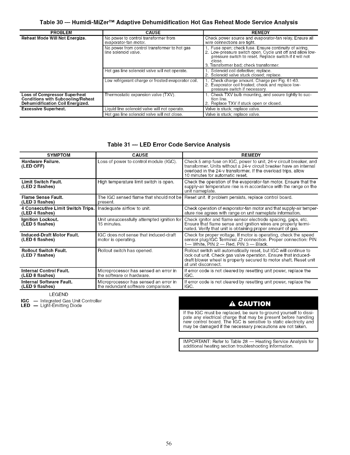
Table 30 -- Humidi-MiZer TM Adaptive Dehumidification Hot Gas Reheat Mode Service Analysis
PROBLEM
Reheat Mode Will Not Energize.
Loss of Compressor Superheat
Conditions with Subcooling/Reheat
Dehumidification Coil Energized.
Excessive Superheat,
CAUSE
No power to control transformer from
evaporator-fan motor.
No power from control transformer to hot gas
line solenoid valve.
Hot gas line solenoid valve will not operate.
Low refrigerant charge or frosted evaporator coil.
Thermostatic expansion valve (TXV).
Liquid line solenoid valve will not operate.
Hot gas line solenoid valve will not close.
REMEDY
Check power source and evaporator-fan relay. Ensure all
wire connections are tight.
1. Fuse open; check fuse. Ensure continuity of wiring.
2. Low-pressure switch open. Cycle unit off and allow low-
pressure switch to reset. Replace switch if it will not
close.
3. Transformer bad; check transformer.
1. Solenoid coil defective; replace.
2. Solenoid valve stuck closed; replace.
1. Check charge amount. Charge per Fig. 61-63.
2. Evaporator coil frosted; check and replace low-
pressure switch if necessary.
1. Check TXV bulb mounting, and secure tightly to suc-
tion line.
2. Replace TXV if stuck open or closed.
Valve is stuck; replace valve.
Valve is stuck; replace valve.
Table 31 -- LED Error Code Service Analysis
SYMPTOM CAUSE REMEDY
Hardware Failure. Loss of power to control module (IGC). Check 5 amp fuse on IGC, power to unit, 24-v circuit breaker, and
(LED OFF) transformer. Units without a 24-v circuit breaker have an internal
overload in the 24-v transformer. If the overload trips, allow
10 minutes for automatic reset.
Limit Switch Fault. High temperature limit switch is open. Check the operation of the evaporator-fan motor. Ensure that the
(LED 2 flashes) supply-air temperature rise is in accordance with the range on the
unit nameplate.
Flame Sense Fault. The IGC sensed flame that should not be Reset unit. If problem persists, replace control board.
(LED 3 flashes) )resent.
4 Consecutive Limit Switch Trips. Inadequate airflow to unit. Check operation of evaporator-fan motor and that supply-air temper-
(LED 4 flashes) ature rise agrees with range on unit nameplate information.
Ignition Lockout. Unit unsuccessfully attempted ignition for Check ignitor and flame sensor electrode spacing, gaps, etc.
(LED 5 flashes) 15 minutes. Ensure that flame sense and ignition wires are properly termi-
nated. Verify that unit is obtaining proper amount of gas.
Induced-Draft Motor Fault. IGC does not sense that induced-draft Check for proper voltage. If motor is operating, check the speed
(LED 6 flashes) motor is operating, sensor plug/IGC Terminal J2 connection. Proper connection: PIN
1-- White, PIN 2 -- Red, PIN 3 -- Black.
Rollout Switch Fault. Rollout switch has opened. Rollout switch will automatically reset, but IGC will continue to
(LED 7 flashes) lock out unit. Check gas valve operation. Ensure that induced-
draft blower wheel is properly secured to motor shaft. Reset unit
at unit disconnect.
Internal Control Fault. Microprocessor has sensed an error in If error code is not cleared by resetting unit power, replace the
(LED 8 flashes) the software or hardware. IGC.
Internal Software Fault. Microprocessor has sensed an error in If error code is not cleared by resetting unit power, replace the
(LED 9 flashes) the redundant software comparison. IGC.
LEGEND
IGC -- Integrated Gas Unit Controller
LED -- Light-Emitting Diode
If the IGC must be replaced, be sure to ground yourself to dissi-
pate any electrical charge that may be present before handling
new control board. The IGC is sensitive to static electricity and
may be damaged if the necessary precautions are not taken.
I IMPORTANT: Refer to Table 28 -- Heating Service Analysis foradditional heating section troubleshooting information. I
56
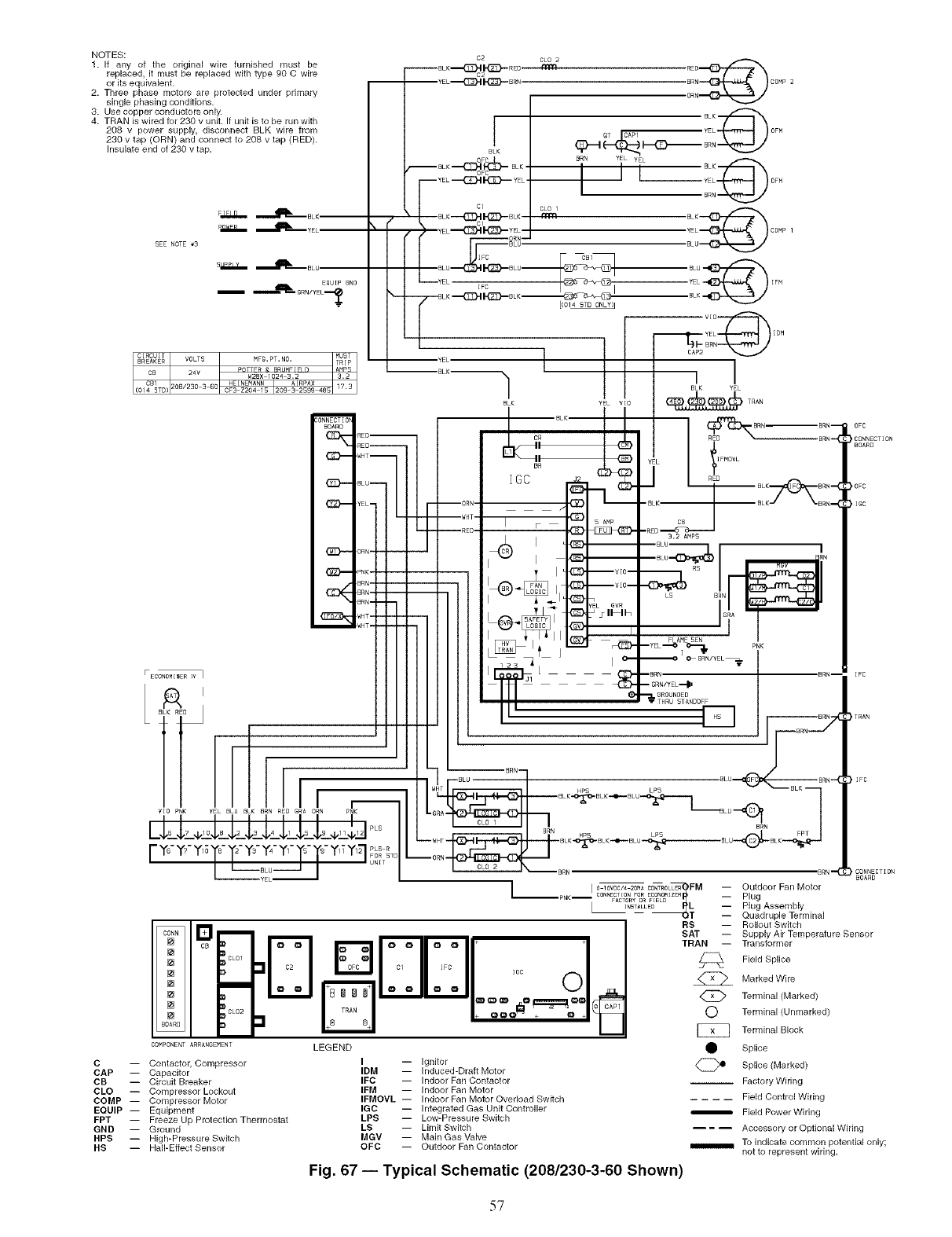
NOTES:
1. If any of the original wire furnished must be
replaced, it must be replaced with type 90 C wire
or its equivalent.
2. Three phase motors are protected under primary
single phasing conditions.
3. Use copper conductors only.
4. TRAN is wired for 230 v unit. If unit is to be run with
208 v power supply, disconnect BLK wire from
230 v tap (ORN) and connect to 208 v tap (RED).
Insulate end of 230 v tap.
I
_ONNECTIOB
BOARD
i
[] ml c2
TRAN
BOARB
COMPONENT ARRANGEMENT LEGEND
C -- Contactor, Compressor
CAP -- Capacitor
CB -- Circuit Breaker
CLO -- Compressor Lockout
COMP -- Compressor Motor
EQUIP -- Equipment
FPT -- Freeze Up Protection Thermostat
GND -- Ground
HPS -- High-Pressure Switch
HS -- Hall-Effect Sensor
.VlO--
.VIO--
SVR
_lh
I
6
:::
LB Bi:L
•_@ O, GRN/YEL_
--BRr] BRN--
I GRN/YEL._I.
"_I. GROUNBED
THRU STANDOFF
I -- Ignitor
IDM -- Induced-Draft Motor
IFC -- Indoor Fan Contactor
IFM -- Indoor Fan Motor
IFMOVL -- Indoor Fan Motor Overload Switch
IGC -- Integrated Gas Unit Controller
LPS -- Low-Pressure Switch
LS -- Limit Switch
MGV -- Main Gas Valve
OFC -- Outdoor Fan Contactor
Fig. 67 i Typical Schematic (208/230-3-60 Shown)
0FC
_CONNECTION
BOARD
_0FC
I_C
TRAN
_'IFC
CONNECTION
BOARD
Outdoor Fan Motor
Plug
Plug Assembly
Quadruple Terminal
Rollout Switch
Supply Air Temperature Sensor
Transformer
Field Splice
Marked Wire
Terminal (Marked)
Terminal (Unmarked)
Terminal Block
Splice
Splice (Marked)
-- Factory Wiring
.... Field Control Wiring
Field Power Wiring
-- --- Accessory or Optional Wiring
To indicate cortlmon potential only;
not to represent wiring.
57
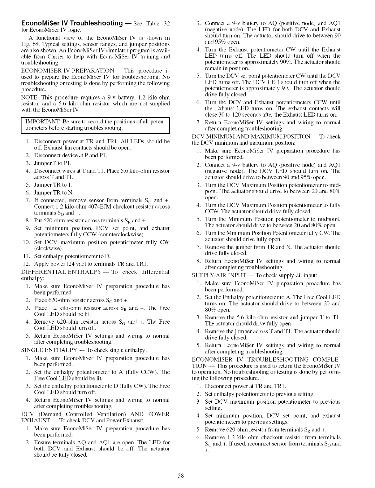
EconoMiSer IV Troubleshooting -- See Table 32
for EconoMi$er IV logic.
A functional view of the EconoMi$er IV is shown in
Fig. 68. Typic:d settings, sensor ranges, and jumper positions
are also shown. An EconoMi$er IV simulator program is avail-
able fiom Carrier to help with EconoMi$er Wmuning and
troubleshooting.
ECONOMI$ER IV PREPARATION -- This procedure is
used to prepare the EconoMi$er IV for troubleshooting. No
troubleshooting or testing is done by performing the following
procedme.
NOTE: This procedure requires a 9-v battely, 1.2 kilo-ohm
resistol: and a 5.6 kilo-ohm resistor which are not supplied
with the EconoMi$er IV.
IMPORTANT: Be sure to record the positions of all poten- ]
tiometers before starting troubleshooting. 1
1. Disconnect power at TR and TRI. All LEDs should be
off. Exhaust fan contacts should be open.
2. Disconnect device at P and PI.
3. Jumper P to PI.
4. Disconnect wires at T and TI. Place 5.6 kilo-ohm resistor
across T and TI.
5. Jumper TR to 1.
6. Jumper TR to N.
7. If connected, remove sensor from terminals So and +.
Connect 1.2 kilo-ohm 4074EJM checkout resistor across
terminals So and +.
8. Put 620-ohm resistor across terminals SR and +.
9. Set minimum position, DCV set point, and exhaust
potentiometers fully CCW (counterclockwise).
10. Set DCV maximum position potentiometer fully CW
(clockwise).
11. Set enthalpy potentiometer to D.
12. Apply power (24 vac) to terminals TR and TRI.
DIFFERENTIAL ENTHALPY-- To check differential
enthalpy:
1. Make sure EconoMiSer IV preparation procedure has
been performed.
2. Place 620-ohm resistor across So and +.
3. Place 1.2 kilo-ohm resistor across SR and +. The Free
Cool LED should be lit.
4. Remove 620-ohm resistor across So and +. The Free
Cool LED should turn off.
5. Return EconoMiSer IV settings and wiring to normal
after completing troubleshooting.
SINGLE ENTHALPY -- To check single enthalpy:
1. Make sure EconoMiSer IV preparation procedure has
been performed.
2. Set the enthalpy potentiometer to A (fully CCW). The
Free Cool LED should be lit.
3. Set the enth_dpy potentiometer to D (fully CW). The Free
Cool LED should turn off.
4. Return EconoMiSer IV settings and wiring to normal
after completing troubleshooting.
DCV (Demand Controlled Ventilation) AND POWER
EXHAUST -- To check DCV and Power Exhaust:
1. Make sure EconoMiSer IV preparation procedure has
been performed.
2. Ensure terminals AQ and AQI _ue open. The LED for
both DCV and Exhaust should be off. The actuator
should be lhlly closed.
3. Connect a 9-v battery to AQ (positive node) and AQl
(negative node). The LED for both DCV and Exhaust
should turn on. The actuator should chive to between 90
and 95% open.
4. Turn the Exhaust potentiometer CW until the Exhaust
LED turns off. The LED should turn off when the
potentiometer is approximately 90%. The actuator should
remain in position.
5. Turn the DCV set point potentiometer CW until the DCV
LED turns off. The DCV LED should turn off when the
potentiometer is approximately 9 v. The actuator should
drive fully closed.
6. Turn the DCV and Exhaust potentiometers CCW until
the Exhaust LED turns on. The exhaust contacts will
close 30 to 120 seconds after the Exhaust LED turns on.
7. Return EconoMi$er IV settings and wiring to normal
after completing troubleshooting.
DCV MINIMUM AND MAXIMUM POSITION -- To check
the DCV minimum and maximum position:
1. Make sure EconoMiSer IV prep_uation procedure has
been performed.
2. Connect a 9-v battery to AQ (positive node) and AQI
(negative node). The DCV LED should turn on. The
actuator should chive to between 90 and 95% open.
3. Turn the DCV Maximum Position potentiometer to mid-
point. The actuator should drive to between 20 and 80%
open.
4. Turn the DCV Maximum Position potentiometer to lhlly
CCW. The actuator should drive fully closed.
5. Turn the Minimum Position potentiometer to midpoint.
The actuator should chive to between 20 and 80% open.
6. Tnrn the Minimum Position Potentiometer lhlly CW. The
actuator should drive fully open.
7. Remove the jumper from TR and N. The actuator should
drive fully closed.
8. Return EconoMiSer IV settings and wiring to norm_d
after completing troubleshooting.
SUPPLY-AIR INPUT -- To check supply-air input:
1. Make sure EconoMi$er IV prepmation procedure has
been performed.
2. Set the Enthalpy potentiometer to A. The Free Cool LED
turns on. The actuator should drive to between 20 and
80% open.
3. Remove the 5.6 kilo-ohm lesistor and jumper T to TI.
The actuator should chive lhlly open.
4. Remove the jumper across T and TI. The actuator should
drive fully closed.
5. Return EconoMiSer IV settings and wiring to norm;d
after completing troubleshooting.
ECONOMISER IV TROUBLESHOOTING COMPLE-
TION -- This procedure is used to return the EconoMiSer IV
to operation. No troubleshooting or testing is done by perform-
ing the following procedure.
1. Disconnect power at TR and TRI.
2. Set enthalpy potentiometer to previous setting.
3. Set DCV maximum position potentiometer to previous
setting.
4. Set minimum position, DCV set point, and exhaust
potentiometers to previous settings.
5. Remove 620-ohm resistor from terminals SR and +.
6. Remove 1.2 kilo-ohm checkout resistor from terminals
So and +. If used, reconnect sensor from terminals So and
+.
58
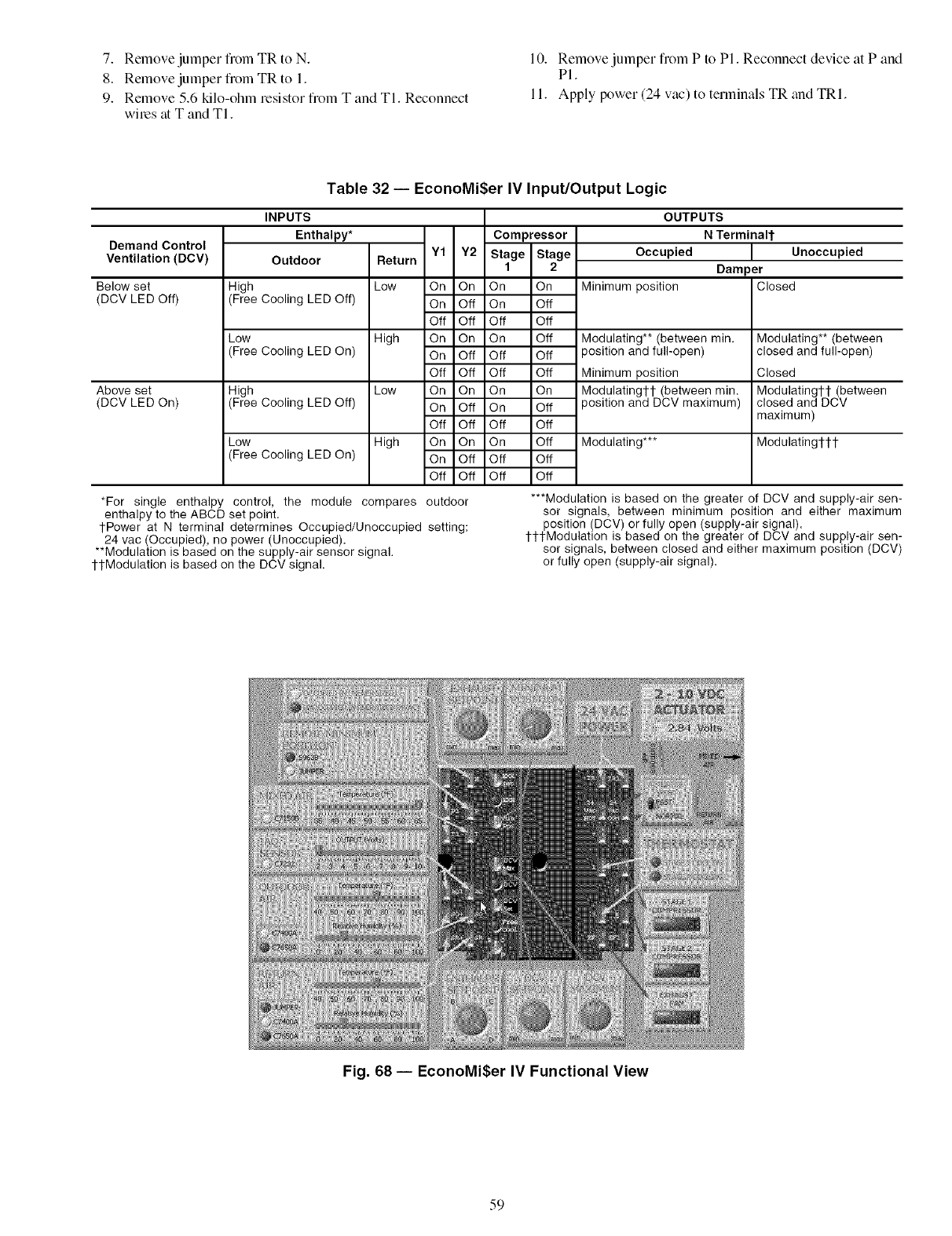
7. Remove jumper flom TR to N.
8. Remove jumper fiom TR to 1.
9. Remove 5.6 kilo-ohm resistor from T and TI. Reconnect
wiles tit T and TI.
l 0. Remove jumper fiom P to Pl. Reconnect device a P and
PI.
11. Apply power (24 vac) to terminals TR and TRI.
Table 32 -- EconoMi$er IV Input/Output Logic
Demand Control
Ventilation (DCV)
Below set
(DCV LED Off)
Above set
(DCV LED On)
High
(Free
Low
(Free
High
(Free
Low
(Free
INPUTS
Enthalpy* Compressor
Outdoor Return Y1 Y2 Stage Stage
1 2
Low On On On On
Cooling LED Off) On Off On Off
Off Off Off Off
High On On On Off
Cooling LED On) On Off Off Off
Off Off Off Off
Low On On On On
Cooling LED Off) On Off On Off
Off Off Off Off
High On On On Off
Cooling LED On) On Off Off Off
Off Off Off Off
*For single enthalpy control, the module compares outdoor
enthalpy to the ABCD set point.
1-Power at N terminal determines Occupied/Unoccupied setting:
24 vac (Occupied), no power (Unoccupied).
**Modulation is based on the supply-air sensor signal.
1-1-Modulation is based on the DCV signal.
OUTPUTS
N Terminal1-
Occupied Unoccupied
Damper
Minimum position Closed
Modulating** (between min.
3osition and full-open)
Minimum position
Modulating1-1- (between rain.
3osition and DCV maximum)
Modulating***
Modulating** (between
closed and full-open)
Closed
Modulating1-1- (between
closed and DCV
maximum)
Modulating1-1-1-
***Modulation is based on the greater of DCV and supply-air sen-
sor signals, between minimum position and either maximum
position (DCV) or fully open (supply-air signal).
I-I-I-Modulation is based on the greater of DCV and supply-air sen-
sor signals, between closed and either maximum position (DCV)
or fully open (supply-air signal).
Fig. 68 -- EconoMi$er IV Functional View
59
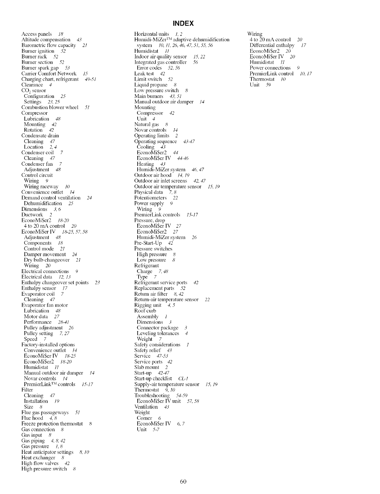
INDEX
Access panels 18
Altitude compensation 43
Barometric flow capacity 21
Burner ignition .52
Burner rack .52
Burner section .52
Burner spark gap 53
Carrier Comfort Network 15
ChaNing chart, refrigerant 49-51
Clearance 4
CO, sensor
Configuration 25
Settings 23, 25
Combustion blower wheel 51
Compressor
Lubrication 48
Mounting 42
Rotation 42
Condensate drain
Cleaning 47
Location 2, 4
Condenser coil 7
Cle_ming 47
Condenser fan 7
Adjustment 48
Control circuit
Wiring 9
Wiring raceway 10
Convenience outlet 14
Demand control ventilation 24
Dehumidification 25
Dimensions 3, 6
Ductwork 2
EconoMi$er2 18-20
4 to 20 mA control 20
EconoMi$er IV 18-2.5, 57, 58
Adjustment 48
Components 18
Control mode 21
Damper movement 24
Dry bulb changeover 21
Wiring 20
Electrical connections 9
Electrical data 12, 13
Enthalpy changeover set points 23
Enthalpy sensor 17
Evaporator coil 7
Cleaning 47
Evaporator fan motor
Lubrication 48
Motor data 27
Performance 28-41
Pulley adjustment 26
Pnlley setting Z 27
Speed 7
Factory-installed options
Convenience outlet 14
EconoMi$er IV 18-25
EconoMi$er2 18-20
Humidistat 11
Manual outdoor air damper 14
Novar controls 14
PremierLink TM controls 15-17
Filter
Cleaning 47
Installation 19
Size 8
Flue gas passageways 51
Flue hood 4,8
Freeze protection thermostat 8
Gas connection 8
Gas input 8
Gas piping 4, 8, 42
Gas pressure 1,8
Heat anticipator settings 8, 10
Heat exchanger 8
High flow valves 42
High pressure switch 8
Horizontal units 1, 2
Humidi-MiZer TM adaptive dehumidification
system 10,11,26,46, 47,51, .5.5,56
Humidistat 11
Indoor air quality sensor 15,22
Integrated gas controller 56
Error codes .52,56
Leak test 42
Limit switch 52
Liquid propane 8
Low pressure switch 8
Main burners 43,51
Manual outdoor air damper 14
Mounting
Compressor 42
Unit 4
Natural gas 8
Novar controls 14
Operating limits 2
Operating sequence 43-47
Cooling 43
EconoMi$er2 44
EconoMiSer IV 44-46
Heating 43
Humidi-MiZer system 46,47
Outdoor air hood 14,19
Outdoor air inlet screens 42,47
Outdoor air temperature sensor 15, 19
Physical data 7,8
Potentiometers 22
Power supply 9
Wiring 9
PremierLink controls 15-17
Pressure, drop
EconoMi$er IV 27
EconoMi$er2 27
Humidi-MiZer system 26
Pre-Start-Up 42
Pressure switches
High pressure 8
Low pressure 8
Refrigerant
Charge 7,48
Type 7
Refrigerant selwice ports 42
Replacement parts .52
Return air filter 8,42
Return-air temperature sensor 22
Rigging unit 4, 5
Roof curb
Assembly 1
Dimensions 3
Connector package 3
Leveling tolerances 4
Weight 7
Safety considerations 1
Safety relief 43
Sel_.'ice 47-53
Selwice ports 42
Slab mount 2
Start-up 42-47
Start-up checklist CL-I
Supply-air temperature sensor 1.5,19
Thermostat 9, 10
Troubleshooting .54-59
EconoMiSer IV unit 5Z .58
Ventilation 43
Weight
Comer 6
EconoMi$er IV 6, 7
Unit 5-7
Wiring
4 to 20 mA control 20
Differential enthalpy 17
EconoMiSer2 20
EconoMiSer IV 20
Humidistat 11
Power connections 9
PremierLink control 10, 17
Thermostat 10
Unit 59
6O

Copyright 2005 Carrier Corporation
Manufacturer reserves the right to discontinue, or change at any time, specifications or designs without notice and without incurring obligations.
Catalog No. 04-53480012-01 Printed in U.S.A. Form 48HJ-32SI Pg 62 9-05 Replaces: 48HJ-28SI
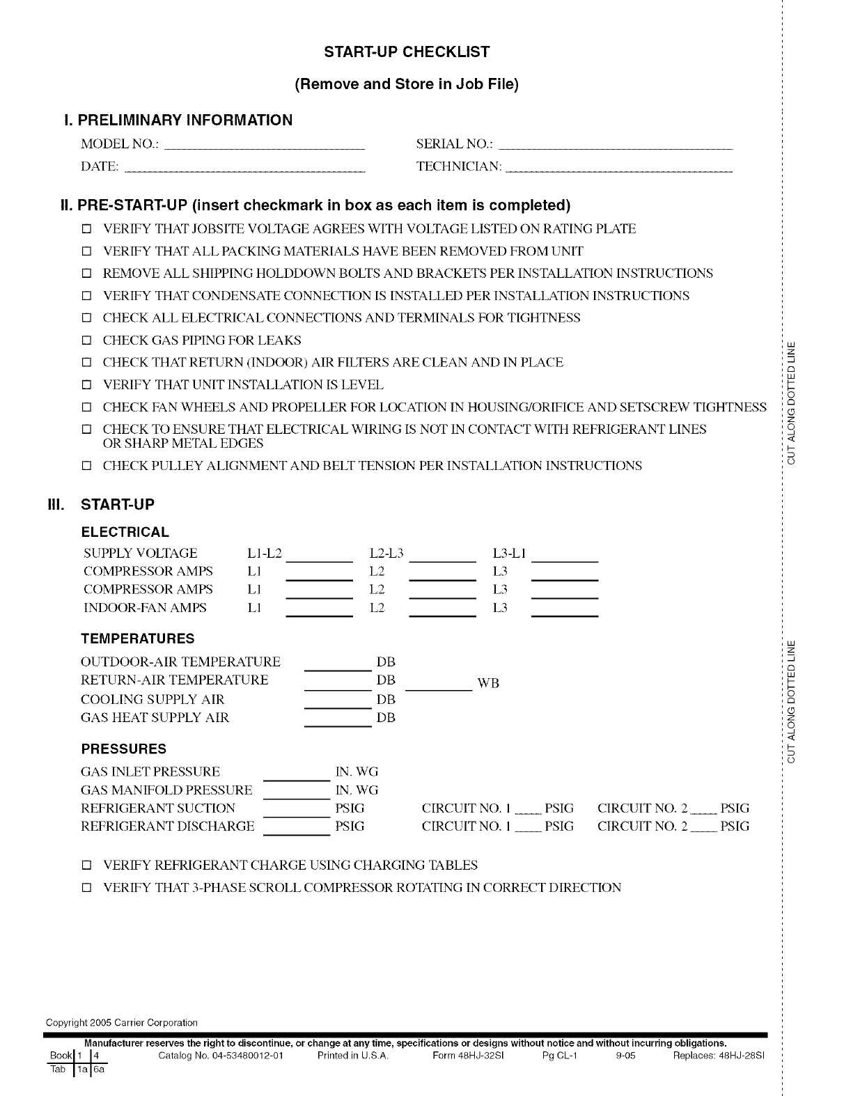
I. PRELIMINARY INFORMATION
MODEL NO.:
DATE:
START-UP CHECKLIST
(Remove and Store in Job File)
SERIAL NO.:
TECHNICIAN:
II. PRE-START-UP (insert checkmark in box as each item is completed)
[] VERIFY THAT JOBSITE VOLTAGE AGREES WITH VOLTAGE LISTED ON RATING PLATE
[] VERIFY THAT ALL PACKING MATERIALS HAVE BEEN REMOVED FROM UNIT
[] REMOVE ALL SHIPPING HOLDDOWN BOLTS AND BRACKETS PER INSTALLATION INSTRUCTIONS
[] VERIFY THAT CONDENSATE CONNECTION IS INSTALLED PER INSTALLATION INSTRUCTIONS
[] CHECK ALL ELECTRICAL CONNECTIONS AND TERMINALS FOR TIGHTNESS
[] CHECK GAS PIPING FOR LEAKS
[] CHECK THAT RETURN (INDOOR) AIR FILTERS ARE CLEAN AND IN PLACE
[] VERIFY THAT UNIT INSTALLATION IS LEVEL
[] CHECK FAN WHEELS AND PROPELLER FOR LOCATION IN HOUSING/ORIFICE AND SETSCREW TIGHTNESS
[] CHECK TO ENSURE THAT ELECTRICAL WIRING IS NOT IN CONTACT WITH REFRIGERANT LINES
OR SHARP METAL EDGES
[] CHECK PULLEY ALIGNMENT AND BELT TENSION PER INSTALLATION INSTRUCTIONS
III. START-UP
ELECTRICAL
SUPPLY VOLTAGE L l -L2
COMPRESSOR AMPS LI
COMPRESSOR AMPS LI
INDOOR-FAN AMPS LI
TEMPERATURES
OUTDOOR-AIR TEMPERATURE
RETURN-AIR TEMPERATURE
COOLING SUPPLY AIR
GAS HEAT SUPPLY AIR
L2-L3 L3-L 1
L2 L3
L2 L3
L2 L3
PRESSURES
GAS INLET PRESSURE
GAS MANIFOLD PRESSURE
REFRIGERANT SUCTION
REFRIGERANT DISCHARGE
DB
DB
DB
DB
WB
IN. WG
IN. WG
PSIG CIRCUIT NO. l
PSIG CIRCUIT NO. l
PSIG CIRCUIT NO. 2 PSIG
PSIG CIRCUIT NO. 2 PSIG
[] VERIFY REFRIGERANT CHARGE USING CHARGING TABLES
[] VERIFY THAT 3-PHASE SCROLL COMPRESSOR ROTATING IN CORRECT DIRECTION
Copyright 2005 Carrier Corporation
Manufacturer reserves the right to discontinue, or change at any time, specifications or designs without notice and without incurring obligations.
Catalog No, 04-53480012-01 Printed in U.S,A, Form 48HJ-32SI Pg CL-1 9-05 Replaces: 48HJ-28SI
LU
2:
m
d3
LU
I--
rm
Z
o,
<
I-
o
LU
2:
m
rm
LU
I--
d3
Z
o,
<
I-
o
