CARRIER Package Units(both Units Combined) Manual L0520548
User Manual: CARRIER CARRIER Package Units(both units combined) Manual CARRIER Package Units(both units combined) Owner's Manual, CARRIER Package Units(both units combined) installation guides
Open the PDF directly: View PDF ![]() .
.
Page Count: 61
50TFF004-007
50TM004-007
Single-Package Rooftop Cooling Units
Installation, Start-Up and
Service Instructions
CONTENTS
Page
SAFETY CONSIDERATIONS ......................... 1
INSTALLATION ................................... 1-47
Step 1 -- Provide Unit Support ...................... l
• ROOF CURB
• SLAB MOUNT
• ALTERNATE UNIT SUPPORT
Step 2 -- Field Fabricate Ductwork .................. 2
Step 3 -- Install External Trap for
Condensate Drain ................................. 2
Step 4 -- Rig and Place Unit ......................... 4
• POSITIONING
Step 5 -- Make Electrical Connections .............. 9
•FIELD POWER SUPPLY
• FIELD CONTROL WIRING
Step 6- Adjust Factory-Installed Options ......... 19
• MANUAL OUTDOOR-AIR DAMPER
• CONVENIENCE OUTLET
• NOVAR CONTROLS
• PREMIERLINK TM CONTROL
• OPTIONAL ECONOMI$ER IV AND ECONOMI$ER2
• ECONOMI$ER IV STANDARD SENSORS
• ECONOMI$ER IV CONTROL MODES
Step 7-- Adjust Evaporator-Fan Speed ............ 31
• DIRECT-DRIVE MOTORS
• BELT-DRIVE MOTORS
PRE-START-UP ..................................... 48
START-UP ....................................... 48-50
SERVICE ........................................ 51-54
TROUBLESHOOTING ............................ 55-58
INDEX .............................................. 59
START-UP CHECKLIST .......................... CL-l
SAFETY CONSIDERATIONS
Installation and servicing ah-conditioning equipment can be
hazardous due to system pressure and electrical components.
Only tlained and qualified service personnel should install,
repair, or service air-conditioning equipment.
Untrained personnel can pedorm basic maintenance func-
tions of cleaning coils and filters and replacing filters. All other
operations should be performed by trained service personnel.
When working on ah-conditioning equipment, observe precau-
tions in the literature, tags and labels attached to the unit, and
other safety precautions that may apply.
Follow all safety codes. Wear safety glasses and work
gloves. Use quenching cloth for unbrazing operations. Have
fire extinguishers available for _dl brazing operations.
Before performing service or maintenance operations on
unit, turn off main power switch to unit and install lockout
tag on disconnect. Ensure voltage listed on unit &Lta plate
agrees with electrical supply provided for the unit. Electri-
cal shock could cause serious personal injury.
INSTALLATION
Unit is shipped in the vertical dischguge configuration. To
convert to horizontal configuration, remove screws from side
duct opening covers and remove covers. Using the same
screws, install covers on vertical duct openings with the
insulation-side down. Seals around duct openings must be
tight. See Fig. 1.
Step 1 -- Provide Unit Support
ROOF CURB -- Assemble and install accesso Uroof curb in
accor&mce with instructions shipped with curb. See Fig. 2.
Install insulation, cant strips, roofing felt, and counter flashing
as shown. Ductwork must be attached to curb, not to unit.
If electric or control power is to be routed through rite basepan,
attach the accessory thru-the-bottom service connections to the
basepan in accor&mce with the accessory installation instruc-
tions. Connection must be installed b@re unit is set on roof
(_rb.
IMPORTANT: The gasketing of the unit to the roof curb
is critical for a watertight seal. Install gasket supplied
with the roof curb as shown in Fig. 2. Improperly
applied gasket can _dso result in air leaks and poor unit
pedbrmance.
Curb should be level. This is necessary for unit drain to
function properly. Unit leveling tolerances are shown in Fig. 3.
Refer to Accessory Roof Curb Installation Instructions for
additional infomtation as required.
Manufacturer reserves the right to discontinue, or change at any time, specifications or designs without notice and without incurring obligations.
Catalog No. 04-53500010-01 Printed in U,SA. Form 50T-5SI Pg 1 9-05 Replaces: 50T-3SI
SLAB MOUNT (Horizontal Units Only) -- Provide a level
conclete slab that extends a minimum of 6 in. beyond unit
cabinet. [nst_dl a gravel apron in front of condenser coil air
inlet to prevent grass and foliage from obstructing airflow.
NOTE: Horizontal units may be installed on a roof curb if
required.
ALTERNATE UNIT SUPPORT -- When file curb or
a&_pter cannot be used, support the unit with sleepers using the
curb or adapter support area. If sleepel.s ctmnot be used, sup-
poll the long sides of the unit with a minimum of 3 equally
spaced 4-in. x 4-in. pads on each side.
Step 2 -- Field Fabricate Ductwork -- Secure _fll
ducts to roof curb and building structure on vertical discharge
units. Do not connect dm_'ork to unit. For horizontal applica-
tions, field-supplied flanges should be attached to horizontal
discharge openings and all ductwork should be attached to the
flanges. Insulate and weatherproof all extern_d ductwork,
joints, and roof openings with counter flashing and mastic in
accor&mce with applicable codes.
Ducts passing through an unconditioned space must be
insulated and covered with a vapor b_uriel:
If a plenum return is used on a vertical unit, the return
should be ducted through the roof deck to comply with applica-
ble fire codes.
A minimum clearance is not requiled around ductwoN.
Cabinet return-air static pressure (a negative condition) should
not exceed 0.35 in. wg with economizer or 0.45 in. wg without
economizel:
Step 3 -- Install External Trap for Condensate
Drain -- The unit's 3/4-in. condensate drain connections are
located at the bottom and side of the unit. Unit discharge
connections do not determine the use of &'ain connections;
either drain connection can be used with vertical or horizont;fl
applications.
When using the standard side drain connection, make sure
the red plug in the alternate bottom connection is tight before
inst;dling the unit.
To use the bottom drain connection for a roof curb installa-
tion, lelocate the factory-installed red plug from the bottom
connection to file side connection. See Fig. 4. The piping for
the condensate drain and external trap can be completed after
the unit is in place. Tile center drain plug looks like a star
connection, howevek it can be removed with a l/2-in, socket
drive extension.
All units must have an extern;d trap for condensate drain-
age. Install a trap at least 4 in. deep and protect against freeze-
up. If drain line is installed downsneam from the external trap,
pitch the line away from the unit at 1 in. per 10 fl of run. Do not
use a pipe size sm;dler than the unit connection (3/4-in.). See
Fig. 5.
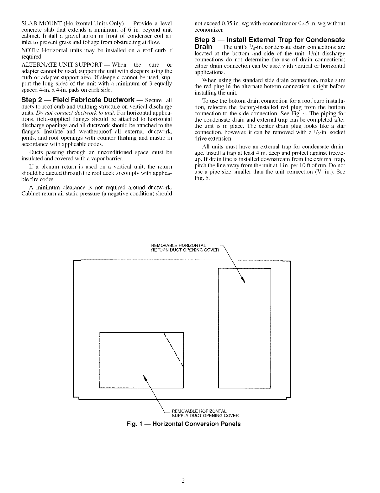
REMOVABLE HORIZONTAL ,,,,,,%
RETURN DUCT OPENING COVER \
\\\\\
\\
___ REMOVABLE HORIZONTAL
SUPPLY DUCT OPENING COVER
Fig. 1 -- Horizontal Conversion Panels

,_'T 7 -, r
CONNECTOR tBtCDRAIN I GAS t POWER t CONTROL IACCESSORY
PKG. ACCY, t t HOLE I t t I PWR
"C'RB-T_IP-W-R0-01"A_'11 I I - "s/_,- -I-_/_, [19] N-P_ r.... s-
"C-_'T_IP-W-R6-'O_'A_'I 1 I I [19] NPT r _1_4,,T3£7z i i
1 -9 /16 1 -4 1 /4 /2•1 3
CRBTMPWROO3A01 I [551] I [406] [44,5] I [12 7] NPT I /4" 19 NPT I [12.7] I [12,7]
......... 4 " " I" " I- -'_ _ - 4, ...... I NPT I NPT
CRBTMPWROO4A01 I I I lOl/_lPT I 11/4•'[31.7] I I
3"
?B]
B"
783
1" 1 7/15"
]41]
I
I
I
I
I
I
I
I
I
I
I
I
I
I
I
I
I
I
I
I
I
I
I
I
I
T
O" O 7/1B"
Ell]
[BOLT HEADS)
0" O 7/1B"
LT [11]
A HEADS)
C
II
C/\ \
/\ J \\
i r.r4
I\/,L'b- ',___1
\/ / /
_i i I
J
BUPPLY AIR I
OPENING C
1_
11' 7 13/1BB3_J 1"1 liB"
[504_, [334]
[7B]
B" O"
[914]
O" O 1/4"E7]
O' 4 9/16"
[115.5]
@
1
I
SUPPLY AIR RETURN AIR _
VIEW "A-A"
1
1
t
1
I
t
1
I
I (SUPPLIED WITH CURB)
t
1
DUCT
I (FIELD BUPPL]ED)
1
1
1
I
1 2" 7 518"
1 [8
1
I
I
I
I
I
O" 0 ?/1B"
[11] •
(BOLT HEADS) A •
O" O 7/1B" •
E._ _A •
[BOLT I
t
GAB BERV[CE
IPLATE
• [BEE NOTE
I
q',l_
q,
t
I
I
HEAD OF BOLT TO BE ON
INS(DE OF FLANGE
........ -RBo-P_tT_-- " -'
ACCESSORY tAiUNIT SIZE
CRRFCURB001A01 tI" ___.-I,
I- L35-6]_1 50TFF, TM
2'@" 004-007
CRRFCURBOO2A01 LI [_610---
NOTES:
1. Roof curb accessory is shipped disassembled.
2. Insulated panels.
3. Dimensions in [ ] are in millimeters.
4. Roof curb: galvanized steel.
5. Attach ductwork to curb (flanges of duct rest on
curb).
6. Service clearance: 4 ft on each side.
7. I_ Direction of airflow.
8. Connector packages CRBTMPWROO1A01 and
002A01 are for thru-the-curb type gas. Packages
CRBTMPWROO3A01 and 004A01 are for thru-
the-bottom type gas connections.
O" 7116"
RIGID INSULATION
(FIELD SUPPLIED)
TYPICAL (4) 5IDES
FLASHING
[FIELD SUPPLIED)
FELT
[FIELD SUPPLIED)
CANT BTRIP
BUPPL]ED)
MATERIAL
(FIELD BUPPLIED)
OPEN(NO FOR BASEPAN ENTRY
SERVICE (SEE NOTE #8)
0' 2 1/2"
O" 31/4"
[83]
SEE NOTE _2
1" 4 13/1B"
[427]
(]NB]DE)
TYP
2 3/B °
[B1]
6"
[152]
[INSIDE)
I
I
I
I
I
l/1B"
VIEW "B"
J[TYP. ALL CORNERS)
O" 1"
[25]
I
3' O 15115"
[93B]
SEE VIEW "P_S,ql-
Fig. 2 -- Roof Curb Details
5" 7 liB"
[1705]
NOTE: CAMBRIBGEPORT "SURE LOCK" CORNER
FASTENING DEVICE IS ACCEPTABLE
ALTERNATE CONSTRUCTION.
c
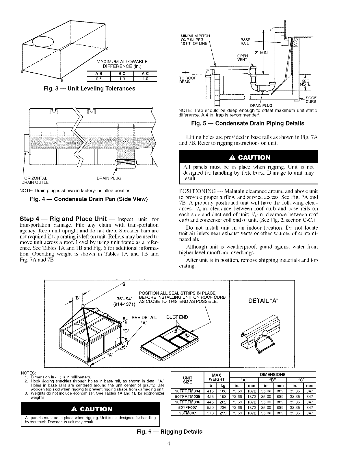
IMUM ALLOWABLE
I_""" I/DIFFERENCE (in.)
I/ A-BI I A-O
o5 I 10 I 1.0
Fig. 3 -- Unit Leveling Tolerances
HORIZONTAL DRAIN PLUG
DRAIN OUTLET
NOTE: Drain plug isshown in factory-installed position.
Fig. 4 -- Condensate Drain Pan (Side View)
Step 4 -- Rig and Place Unit-- Inspect unit for
transportation &unage. File any claim with transpom_tion
agency. Keep unit upright and do not drop, Spreader bars are
not required if top crating is left on unit. Rollel_ may be used to
move unit across a roof. Level by using unit fi_lme as a refer-
ence. See Tables IA and IB and Fig. 6 for additional informa-
tion, Operating weight is shown in Tables IA and IB and
Fig. 7A and 7B.
MINIMUM PITCH TI I I_], --_ __
ONE IN. PER BASE
,0PTOPL,NE\ I
OPEN2'M,NI ] //]1
....
TO ROOF
DRAIN SEE
NOTE
_L_
ROOF
CURB
DRAIN PLUG
NOTE: Trap should be deep enough to offset maximum unit static
difference. A 4-in. trap is recommended.
Fig. 5 -- Condensate Drain Piping Details
Lifting holes are provided in base rails as shown in Fig. 7A
and 7B. Refer to rigging instructions on unit.
All panels must be in place when rigging. Unit is not
designed for handling by fork truck. Dmnage to unit may
result.
POSITIONING -- Maintain cletuance around and above unit
to provide proper airflow and service access. See Fig. 7A and
7B. A properly positioned unit will have the following clear-
ances: l/4-in, cletuance between roof curb and base nfils on
each side and duct end of unit; l/4-in, clearance between roof
curb and condenser coil end of unit. (See Fig. 2, section C-C.)
Do not install unit in an indoor location. Do not locate
unit air inlets near exhaust vents or other sources of contami-
nated all:
Although unit is weatherproof, guard against water from
higher level runoff and overhangs.
After unit is in position, remove shipping materials and top
crating.
POSITION ALL SEAL STRIPS IN PLACE
"- 54" BEFORE INSTALLING UNIT ON ROOF CURB
(914.1371) AS CLOSE TO THIS END AS POSSIBLE.
BEE T ,,BBOT NO
-C _
NOTES:
1. Dimension in ( ) is in millimeters,
2, Hook rigging shackles through holes in base rail, as shown in detail "A,"
Holes in base rails are centered around the unit center of gravity. Use
wooden top skid when rigging to prevent rigging straps from damaging unit.
3, Weights do not include economizer, See Tables 1A and 1B for economizer
weights,
All panels must be in place when rigging. Unit is not designed for handling
by fork truck. Damage to unit may result.
MAX
UNIT WEIGHT
SIZE Ib kg
50TFF, TM004 415 188
50TFF, TM005 425 193
50TFF, TM006 445 202
50TFF007 520 236
50TM007 570 259
DETAIL "A"
DIMENSIONS
"A .... B .... C"
in, mm in. mm in, mm
73.69 1872 35.00 889 33,35 847
73.69 1872 35,00 889 33,35 847
73.69 1872 35.00 889 33,35 847
73.69 1872 35.00 889 33,35 847
73.69 1872 35.00 889 33,35 847
Fig. 6 -- Rigging Details
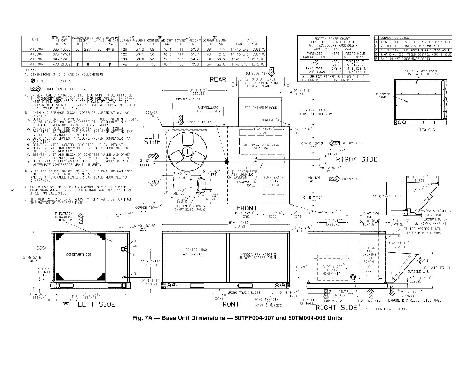
STD. UNiT ECONOM[$ER[V VERT. ECON IV (A) (B) (C) (D3
UNiT WEIGHT WEIGHT _/ PIEI WEIGHT CORNER WEIGHT CORNER WEIGHT CORNER WEIGHT CORNER WEIGHT
LB KO LB KO LB KG LB KG LB KO LB KO LB KG
50T 004 365 1SSI8 50 22.7 90 40.9 126 57.2 89 40.4 111 50.3 39 17.7
50T 005 375 170.1 128 58.1 90 40.8 114 51.7 43 19.5
SOT 008 395 179.2 132 59.9 94 42.5 120 54.4 49 22.2
50TFFO07 470 213.2 148 57.1 103 45.7 155 70.3 B4 29.0
NOTED:
1. DIMENSIONS IN [ ] ARE IN MILLIMETERS.
2. I_CENTER OF GRAVITY.
3. DIRECTION OF AIR FLOW.
4. ON VERTICAL DISCHARGE UNITS, DUCTWORK TO BE ATTACHED
TO ACCESSORY ROOF CURB ONLY. FOR HORIZONTAL DISCHARGE
UNITS FIELD SUPPLIED FLANGES SHOULD BE ATTACHED TO
HORIZONTAL DISCHARGE OPENINGS, AND ALL DUCTWORK SHOULD
BE ATTACHED TO THE FLANGED.
5. MINIMUM CLEARANCE (LOCAL CODES OR JURISDICTION MAY CORNER
PREVAIL]= "A"
a. BOTTOM OF UNiT TO COMBUSTIBLE SURFACES (WHEN NOT USING \
CURB) I INCH. BOTTOM OF BASE RAiL TO COMBUSTIBLE \
SURFACED (WHEN NOT USING CURB) 0 INCHED.
b. CONDENSER COIL, FOR PROPER AIR FLOW, 35 iNCHED I_LEFT
ONE SIDE, 12 INCHES THE OTHER. THE SIDE GETTING THE
GREATER CLEARANCE iS OPTIONAL,
c. OVERHEAD, 60 INCHES TO ASSURE PROPER CONDENSER FAN
OPERATION. /SID E
d. BETWEEN UNITS, CONTROL BOX SIDE, 42 IN. PER NEC.
e. BETWEEN UNIT AND UNGROUNDED BURFACEB, CONTROL BOX
BIDE, 38 IN. PER NEC.
fI BETWEEN UNIT AND BLOCK OR CONCRETE WALLS AND OTHER /
GROUNDED SURFACES, CONTROL BOX SIDE, 42 iN. PER NEC. /
9" HORIZONTAL SUPPLY AND RETURN END, 0 INCHES WHEN THE 3' B"
ALTERNATE CONDENSATE DRAIN IS USED. [I144]
5. WITH THE EXCEPTION OF THE CLEARANCE FOR THE CONDENSER
COIL AS STATED iN NOTE #5o, b,
AND c, A REMOVABLE FENCE OR BARRICADE REQUIRES NO
CLEARANCE. 2' 1/2"
7. UNITS MAY BE INSTALLED ON COMBUSTIBLE FLOORS MADE [G22]
FROM WOOD OR CLASS A, B, OR C ROOF COVERING MATERIAL
iF SET ON BASERAIL.
B. THE VERTICAL CENTER OF GRAVITY iS 1' 5"[457] UP FROM
THE BOTTOM OF THE BASE RAIL.
2" B B/1B"
EB4B.B]
BOTTOM
OF UNIT
"A"
PANEL LENGTH
I' IO 3/B" E5BB.O]
I' 10 3/8" [588.0]
I" 0 3/8" [315.0]
l' 0 3/8" [31S.O]
OUTSIDE AIR 8
REAR [ POWER EXHAUST
3" 1 1/2"_
BOTTOM POWER CHART=
THESE HOLE5 REQ'D FOR USE
WiTH ACCESSORY PACKAGES
CRBTMPWROOIA01, 2A01
THREADED WIRE REQ'D HOLE
CONDUIT SIZE USE SIZES (MAX.)
1/2" ACC. 7/8"[22.2]
1/2" 24V 7/B'[22.2]
3/4" (001) POWER_ 1 1/8"[28.4]
1 1/4" (002) POWER_ 1 3/4"[44.4]
SELECT EITHER 3/4" OR 1 1/4"
FOR POWER r DEPENDING ON WIRE SIZE.
O" 4 1/2"
CORNER "D _
ELECTRICAL . . CORNER "D"
D I SCONNECT A
LOCAT BN
_ / _] i_0' 387113Z18"
CONDENSER COIL
'(21LI]B"
3' 5 BZ1S'_TYP [1045]
B/1 B"
EBB] LEFT SIDE
[952.5]
CONDENSER COIL
COMPRESSOR
ACCESS COVER
8 SEE NOTE #8_ \
ECONOMISER IV HOOD
CORNER "B_
I RETURN AIR OPENING I
I VERTICAL I
I
_[114]
1' 51/4 _ [43B]
FOR ECONOM[$ER IV
_0' 3 3/16"
[81 ]
O" 10 115/15" _ RETURN AIR
[27B]
O" 5 3/8"
[I 37] RIGHT 51DE
FILTER ACCESS PANEL
(OlSPOSABLE FILTERS)
BLOCKOFF
PANEL
O0
VIEW S S
Fig. 7A -- Base Unit Dimensions -- 50TFF004-007 and 50TM004-006 Units

UNIT
SOTMO0?
NOTES:
1. DIMENSIONS IN [ ] ARE IN MILLIMETERS.
2. _CENTER OF GRAVITY.
S. _ DIRECTION OF AIR FLOW.
ELECTRICAL I_ _I'
DISCONNECT _362]
LOCATION
CONDENSER COIL
O' 4 I/IS" 3" 5 3/15"
[115.8] TYP [1046]
9/15"
Ess_LEFT SIDE
O" 3 13/15"
l' 4 S/IS"
[414.5]
O" 8 5/8 °
E168.2]
d
OUTSIOEAIR
REAR
[S15] 5" 1 11/15"
2' 10"
[854]
CONTROL BOX/COMPRESSOR
PANEL
POWER EXHAUST
BOTTOM POWER CHART:
THE5E HOLE5 REQ'D FOR U5E
WITH ACCESSORY PACKAGES
CRBTMPWROOIAOI, 2AOl, 3AOI, OR 4AOl
THREADED WIRE REQ'D HOLE
CONDUIT SIZE USE 5IZE5 (MAX,]
1/2" ACC, 7/8"[22,2]
1/2" 24V 7/8"[22.2]
3/4" (001,003) "OWER_ 1 1/8"[28,4]
1/4" (O02,004)'OWER_ 1 3/4°[44.4]
[003) 1/2"FPT GAS 1 1/4"[31.8]
[004) 3/4"FPT GAS 1 5/8"[41.3]
SELECT EITHER 3/4" OR 1 1/4"
FOR POWER, DEPENDING ON WIRE SIZE.
O' 4 1/2"
_[114] FILTER ACCESS
(DISPOSABLE FILTERS)
1' 5 1/4" [438]
FOR ECONOMIZER IV
_0" 3 3/1B"
E_. RIGHT SIDE
I _ RETURN AIRO' 10 15X16 °
[27B]
O' 53/8"
_ [137]
_0' 2 9/16"
[BS]
1" [451153/4" _ SUPPLY AIR
BLOCKOFF
PANEL
O" 5 7/16" 1' 8 1
[138]
i:O;T;IS::I:POWERSUppLyKNoCKOUT
A 1 3/8" DIAI [35] FIELD POWER SUPPLY HOLE
2" DIA. [51] POWER SUPPLY KNOCK OUT
1 3/4" DIA, [44] CHARGING PORT HOLE
7/8" DIA. [22] FIELD CONTROL WIRING HOLE
3/4" 14 NPT CONDENSATE DRAIN
oo r---1
VIEW SS
7/1B°EllI1]
"C" O' ?1/4"
[81] _ [184] VERTICAL
1" 5 5/18" s" lO 13/16" O' 4 1/15" ECONOMISER IV
Fig. 7B -- Base Unit Dimensions -- 50TM007 Units
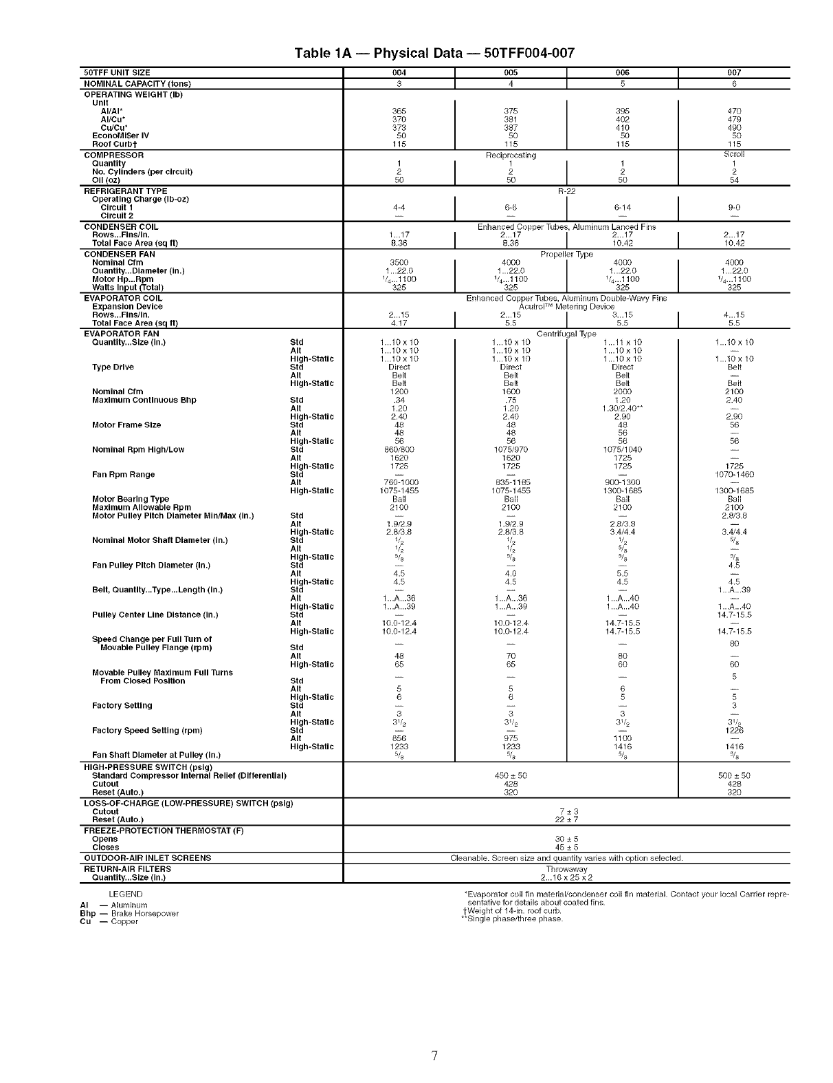
Table1A-- Physical Data -- 50TFF004-007
80TFF UNIT SIZE 004 J 005 t006 +007
NOMINAL CAPACITY (tons) 3 4 5 6
OPERATING WEIGHT (Ib)
Unit
AI/AI* 365 470
AI/Cu* 370 479
Cu/Cu* 373 490
EconoMl$er IV 50 50
Root Curbt 115 115
COMPRESSOR Scroll
Quantity 1 1
No. Cylinders (per circuit) 22
OII (oz) 50 54
REFRIGERANT TYPE
Operating Charge (Ib-oz)
Circuit 1 4-4 9-0
Circuit 2-- --
CONDENSER COIL
Rows...Flns/In. 1...17 I I 2...17Total Face Area (sq ft) 8.36 10.42
CONDENSER FAN
Nominal Cfm 8500 4000
Quantlty...Dlameter (in.) 1 ...22.0 1...22.0
Motor Hp...Rpm 1/4...1100 V4...1100
Watts Input (Total) 325 825
EVAPORATOR COIL
Expansion Device
Rows...Fins/,n. 2...15 I I 4...15
Total Face Area (sq ft) 4.17 5.5
EVAPORATOR FAN
QuanUty...Slze (in.)
Type Drive
Nominal Cfm
Maximum Continuous Bhp
Motor Frame Size
Nominal Rpm High/Low
Fan Rpm Range
Btd
AIt
High-Static
Btd
Air
High-Static
Std
AIt
High-Static
Btd
AIt
High-Static
Std
AIt
High-Static
Std
AIt
High-Static
Motor Bearing Type
Maximum Allowable Rpm
Motor Pulley Pitch Diameter MIn/Max (in.) Std
Air
High-Static
Nominal Motor Shaft Diameter (in.) Std
Air
High-Static
Fan Pulley Pitch Diameter (in.) Std
Air
High-Static
Belt, QuanUty...Type...Length (in.) Std
Air
High-Static
Pulley Center Line Distance (in.) Btd
Air
High-Static
Speed Change per Full Turn of
Movable Pulley Flange (rpm) Std
Air
High-Static
Movable Pulley Maximum Full Turns
From Closed Position Std
Air
High-Static
Factory Setting Std
Air
High-Static
Factory Speed Setting (rpm) Btd
AIt
High-Static
Fan Shaft Diameter at Pulley (in.)
HIGH-PRESSURE SWITCH (peig)
Standard Compressor Internal Relief (DifferenUal)
Cutout
Reset (Auto.)
LOBS-OF-CHARGE (LOW-PRESSURE) SWITCH (psig)
Cutout
Reset (Auto.)
FREEZE-PROTECTION THERMOSTAT (F)
Opens
Closes
OUTDOOR-AIR INLET SCREENS
RETURN-AIR FILTERS
QuanUty...Size (in.)
1...10 x 10
1...10 x 10
1...10 x 10
Direct
Belt
Belt
1280
.34
1.20
2.40
48
48
56
860/800
1620
1725
76_ 800
1075-1455
Ball
2100
1._.9
2.8/3.8
5/8
2;
4.6
1..._.g8
1...A...g9
10._2.4
10.0-12.4
48
65
5
6
T
3V2
1233
5/8
375 395
381 402
387 410
50 50
115 115
Reciprocating
1 1
2 2
50 50
R-22
6-6 6-14
Enhanced Copper Tubes, Aluminum Lanced Fins
2...17 I 2...178.36 10.42
Propeller Type
4000 4000
1...22.0 1...22.0
1/4...1100 1/4...1100
325 325
Enhanced Copper Tubes, Aluminum Double-Wavy Fins
AcutroP M Metering Device
2...15 I 3...155.5 5.5
Centrifugal Type
1...10x 10 1...11x 10
1...18 x 10 1...10 x 10
1...18 x 10 1...10 x 10
Direct Direct
Belt Belt
Belt Belt
1600 2000
.75 1.20
1.28 1.30/2.48"*
2.48 2.90
48 48
48 56
56 56
1875/970 1075/1040
1620 1725
1725 1725
900-_300
1300-1685
Ball
2100
83_185
1075-1455
Ball
2100
1_9 2_8
2.8/3.8 3.4/4.4
1/2 V2
1/2 5/8
5/s 5/8
2; 5%
4.5 4.5
1..._.36
1...A...39
10._2.4
10.0-12.4
1...A...40
1...A...40
14._5.5
14.7-15.5
6
5
T
3_/2
i_o
1416
5/8
7O
65
5
6
T
3V2
1233
5/8
1...10 x 10
1...10 x 10
Belt
Belt
2100
2.40
2%
56
1_6
1070-1480
130_ 686
Ball
2100
2.8/3.8
3.4_.4
s/8
4.5
2;
1...A...39
1..._.40
14.7-15.5
14._5.5
8O
5
3
1226
1_6
5/8
450 ± 50 500 ± 50
428 428
320 320
7±3
22±7
30±5
45±5
Cleanable. Screen size and quantity varies with option selected.
Throwaway
2...16 x 25 x 2
LEGEND
AI -- Aluminum
Bhp -- Brake Horsepower
CU -- Copper
*Evaporator coil fin material/condenser coil fin material. Contact your local Carrier repre-
sentative 1or details about coated fins.
1-Weight of 14-in. roof curb.
**Single phase/three phase.
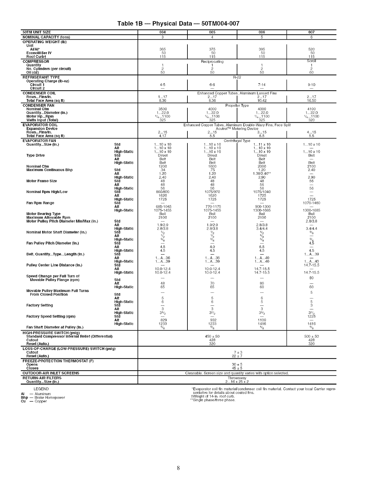
Table 1B -- Physical Data -- 50TM004-007
50TM UNIT SIZE 004 _005 t 006 t007
NOMINAL CAPACITY (tons) 3 486
OPERATING WEIGHT (Ib)
Unit I
AI/AI* 365 375 395 520
EconoMl$er IV 50 50 50 50
Roof Curbt 115 115 115 115
COMPRESSOR Reciprocating Scr()ll
Quantity 1I1I1 1
No. Cylinders (per circuit) 2 2 2 2
OII (oz) 50 50 50 B0
REFRIGERANT TYPE R-22
Operating Charge (Ib-oz) I I
Circuit 14-5 6-6 7-14 9-10
Circuit 2....
CONDENSER COIL Enhanced Copper Tubes, Aluminum Lanced Fins
Rows...Fins/in. 1...17 I2...17 I2...17 I2...17
Total Face Area (sq ft) 8.36 8.36 10.42 16.50
CONDENSER FAN Propeller Type
Nominal Cfm 3500 I4000 I4000 4100
Quantlty...Dlameter (in.) 1 ...22.0 I1...22.0 I1...22.0 1...22.0
Motor Hp...Rpm V4...1100 1/4...1100 1/4...1100 1/4...1100
Watts Input (Total) 325 325 325 320
EVAPORATOR COIL Enhanced Copper Tubes, Aluminum DouHe-Wavy Fins, Face Split
Expansion Device AcutroP M Metering Device
ROWS...F,n s/,n. 2...18 I 2...18 I 4...18TONI Face Area (sq ft) 4.17 5.5 5.5
EVAPORATOR FAN
Quantity...Size (in.)
Type Drive
Nominal Ctm
Maximum ConUnuous Bhp
Motor Frame Size
Nominal Rpm High/Low
Fan Rpm Range
Motor Bearing Type
Maximum Allowable Rpm
Motor Pulley Pitch Diameter MIn/Max (in.)
Nominal Motor Shaft Diameter (in.)
Fan Pulley Pitch Diameter (in.)
Belt, Ouantlty...Type...Length (In.)
Pulley Center Line Distance (in.)
Speed Change per Full Turn of
Movable Pulley Flange (rpm)
Movable Pulley Maximum Full Turns
From Closed Position
Factory Setting
Factory Speed Setting (rpm)
Std
AIt
High-Static
Std
AIt
High-Static
Std
AIt
High-Static
Std
AIt
High-Static
Std
AIt
High-Static
Std
AIt
High-Static
Std
AIt
High-Static
Std
AIt
High-Static
Std
AIt
High-Static
Btd
AIt
High-Static
Std
AIt
High-Static
Std
AIt
High-Static
Std
AIt
High-Static
Std
Air
High-Static
Std
Air
High-Static
1...10 x 10
1...10 x 10
1...10 x 10
Direct
Belt
Belt
1200
.34
1.20
2.40
48
48
56
860/800
1620
1725
68_ 045
1075-1455
Ball
2100
1.9_.9
2.8/3.8
1/2
1/2
5/8
4.5
4.5
1..._.36
1 ...A...39
10._2.4
10.0-12.4
LOSS-OF-CHARGE (LOW-PRESSURE) SWITCH (peig)
Cutout
Reset (Auto.)
FREEZE-PROTECTION THERMOSTAT (F)
Opens
Closes
OUTDOOR-AIR INLET SCREENS
RETURN-AIR FILTERS
Quantl_...Slze !In.}
LEGEND
AI -- Aluminum
Bhp -- Brake Horsepower
Cu -- Copper
5
6
T
31/2
829
1233
5/8
1...10 x 10
1...10 x 10
1...10 x 10
Direct
Belt
Belt
1600
.75
1.20
2.40
48
48
56
1075/970
1620
1725
77_ 175
1075-1455
Ball
2100
1.9_.9
2.8/3.8
1/2
1/2
5/8
25
4.5
1..._.36
1...A...39
10._2.4
10.0-12.4
7O
65
5
6
T
3V2
;;2
1233
5/8
I 3...155.5
Centrifugal Type 1...11 x 10
1...10 x 10
1...10 x 10
Direct
Belt
Belt
2000
1.20
1.30/2.40"*
2.90
48
56
56
1075/1040
1725
1725
90_ 300
1300-1685
Ball
2100
2._3.8
3.4/4.4
1/2
5/8
5/8
4.5
1..._.40
1...A...40
14._5.5
14.7-15.5
8O
6O
6
5
T
3V2
i_o
1416
5/8
1...10 x 10
1...10 x 10
Belt
Belt
2100
2.40
2%
56
1_8
1070-1480
130_ 685
Ball
2100
2.8/3.8
3._.4
5/8
_8
4.5
z;
1...A...39
1..._.40
14.7-15.5
14._5.5
8O
5
1225
1_6
5/8Fan Shaft Diameter at Pulley (in.)
HIGH-PRESSURE SWITCH (pelg)
Standard Compressor Internal Relief (Differential) 450 ± 50 500 ± 50
Cutout 428 428
Reset (Auto.) 320 320
7±3
22±7
30±5
45±5
Cleanable. Screen size and quantity varies with option selected.
Throwaway
2...1B x 25 x 2
*Evaporator coil fin material/condenser coil fin material. Contact your local Carrier repre-
sentative for details about coated fins.
1-Weight of 14-in. roof curb.
**Single phase/three phase.
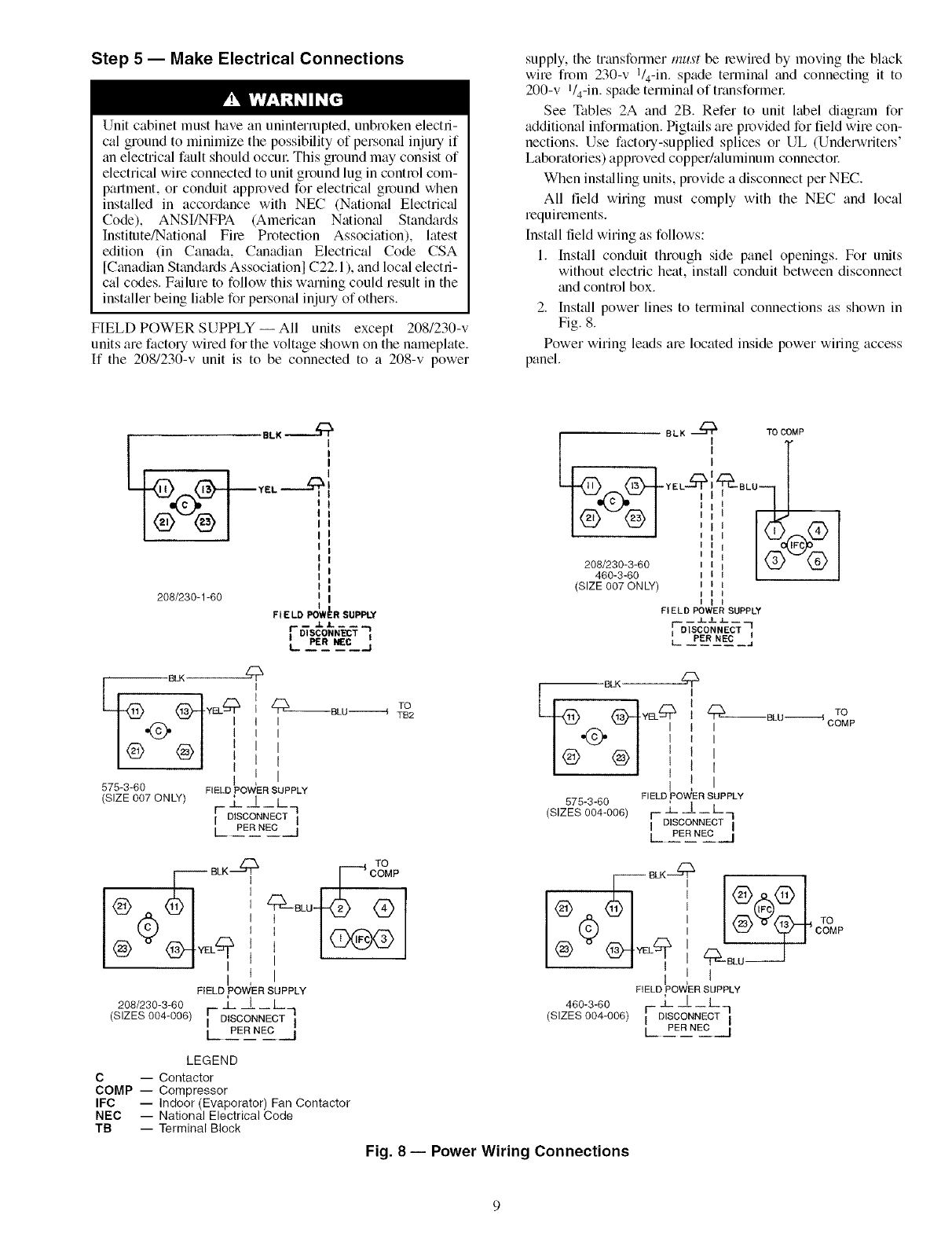
Step 5 -- Make Electrical Connections
Unit cabinet must have an uninterrupted, unbroken electri-
cal ground to minimize the possibility of personal inju Uif
an electrical fault should occm_ This ground may consist of
electrical wire connected to unit ground lug in control com-
partment, or conduit appl_wed for electrical gl_mnd when
installed in accordance with NEC (National Electrical
Code), ANSI/NFPA (American Natiomd Standards
Institute/National Fire Protection Association), latest
edition (in Cana&L, Canadian Electrical Code CSA
[Canadian Standards Association] C22.1 ), and local electri-
cal codes. Ftdlure to follow this warning could result in the
installer being liable for pel_onal inju Uof others.
FIELD POWER SUPPLY--All units except 208/230-v
units are factory wired for the voltage shown on the nameplate.
If the 208/230-v unit is to be connected to a 208-v power
supply, the transformer must be rewired by moving the black
wire from 230-v l/4-in, spade terminal and connecting it to
200-v V4-in. spade terminal of transformel_
See Tables 2A and 2B. Refer to unit label diagram for
additional information. Pigtails are pl_wided for field wire con-
nections. Use factou-supplied splices or UL (Undel_ritel_'
Laboratories) approved copper/aluminum connectol_
When inst_dling units, provide a disconnect per NEC.
All field wiring must comply with the NEC and local
requirements.
Inst_dl field wiring as follows:
1. Inst_dl conduit through side panel openings. For units
without electric heat, install conduit between disconnect
and contl_l box.
2. Inst_dl power lines to terminal connections as shown in
Fig. 8.
Power wiring leads are located inside power wiring access
panel.
208/230-1-60
L _R_ =_%.
BLK
L '
(SIZE 007 ONLY)
TO COMP
FIELD POWER SUPPLY
__ J-JL .L__
F--DISCONN ECT -I
PER NEC I
L- ..... .J
'BLK _
575-3-60 1
(SIZE 007 ONLY)
_ BLU --------_ TTBO2
I
I
I
[
I
F_ELD POWER SUPPLY
r--_- ._ L q
I DISCONNECT I
[ PER NEC j
BLK_
I L 0LD---- o Op
FIELD POWER SUPPLY
575-3-60
(SIZES 004-006) r- _L _!.1_ L_I
IDISCONNECT I
IPER NEC I
, I 0 °P
Q:4
I I
FIELD POWER SUPPLY
208/230-3-60 _L _L _ L
(SIZES 004-006) F DISCONNECT q
[ PER NEO U
1_ BLK_
@_)_ O_)OMP
FIELD POWER SUPPLY
480-3-80 F-j- I L
(SIZES 004-006) I DISC-ON_OTq
LPER NEO l
LEGEND
C -- Contactor
COMP -- Compressor
IFC -- Indoor (Evaporator) Fan Contactor
NEC -- National Electrical Code
TB -- Terminal Block
Fig. 8 -- Power Wiring Connections
FIELD CONTROL WIRING -- Install a CmTier-approved
accessory thermostat assembly according to installation
instructions included with the accessory. Locate thermostat
assembly on a solid wall in the conditioned space to sense aver-
age temperature in accordance with thermostat installation
instructions. Connect thermostat wires to terminal board.
Route thermostat cable or equiv¢dent single leads of colored
wire from subbase terminals to low-voltage connections on
unit (shown in Fig. 9).
NOTE: For wire runs up to 50 ft, use no. 18 AWG (American
Wile Gage) insulated wire (35 Cminimum). For 50 to 75 ft,
use no. 16 AWG insulated wire (35 Cminimum). For over
75 fl, use no. 14 AWG insulated wire (35 Cminimum). All
wire lmger than no. 18 AWG cannot be directly connected to
the thermostat and will require a junction box and splice at the
thermostat.
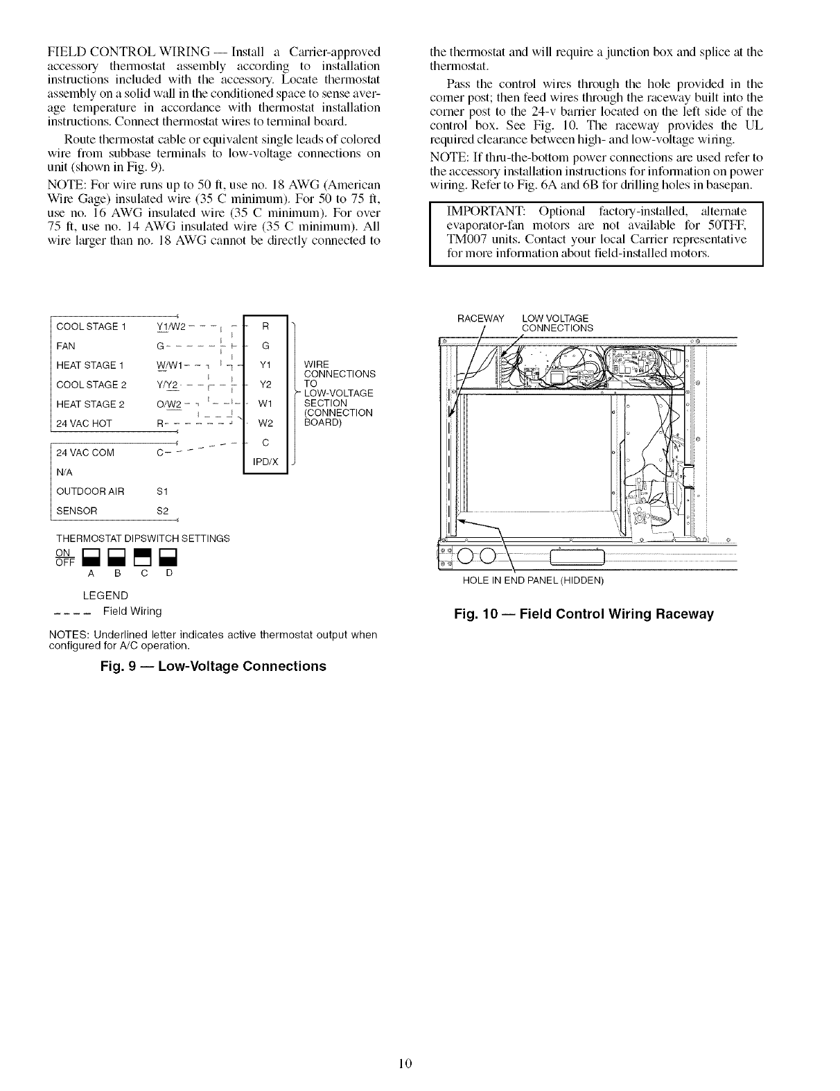
Pass the control wiles through the hole provided in the
corner post; then feed wires through the raceway built into the
corner post to the 24-v barrier located on the left side of the
control box. See Fig. 10. The laceway provides the UL
required clearance between high- and low-voltage wiling.
NOTE: If thin-the-bottom power connections are used refer to
the accessory installation instructions for information on power
wiring. Refer to Fig. 6A and 6B for &illing holes in basepan.
IMPORTANT: Optiomfl factory-installed, _flternate
evaporator-fan motors are not available for 50TFF,
TM007 units. Contact your local Carrier representative
for more information about field-installed motors.
COOL STAGE 1
FAN
HEAT STAGE 1
COOL STAGE 2
HEAT STAGE 2
24 VAC HOT
24 VAC COM
N/A
OUTDOOR AIR $1
SENSOR $2
m
Y1/W2- - -I _ " R
G ..... L{_ .G
I
w/wl--_ _ - Y1
Y/Y2 'r i- " Y2
O/W2- _ i_ -t- .Wl
1_ |
R- - _- W2
C- _ IPD/X
WIRE
CONNECTIONS
TO
= LOW-VOLTAGE
SECTION
(CONNECTION
BOARD)
THERMOSTAT DIPSWITCH SETTINGS
ON
A B C D
LEGEND
Field Wiring
NOTES: Underlined letter indicates active thermostat output when
configured for A/C operation.
Fig. 9 -- Low-Voltage Connections
RACEWAY LOW VOLTAGE
CONNECTIONS
HOLE IN END PANEL(HIDDEN)
Fig. 10- Field Control Wiring Raceway
10

Table 2A -- Electrical Data (Without Convenience Outlet)
5OTFF,TM
UNIT
SIZE
004
NOMINAL
V-PH-Hz
208/230-1-60 --
IFM
TYPE
STD
ALT
STD
208/230-3-60 ALT 187 254 1
HIGH
STD
460-3-60 ALT 414 508 1
HIGH
VOLTAGE COMPRESSOR HEATER
RANGE (ea) OFM(ea) IFM MODEL NO,
Min Max Oty RLA LRA Qty Hp FLA FLA CRHEATER---A00
187 254 1 16.2 96 1 1/4 1.4
10.2 75 1 1/4 1.4 4.9
4.4 40 1 1/4 0.8 2.1
NONE
001
3.5 002
003
004
002 and 002
NONE
O01
OO2
4.9 003
OO4
002 and 002
NONE
O01
3.5 002
0O3
004
OO5
NONE
O01
OO2
OO3
O04
OO5
NONE
O01
5.2 002
OO3
004
OO5
NONE
OO6
1.3 007
008
OO9
NONE
OO6
OO7
008
OO9
NONE
OO6
2.6 007
0O8
OO9
NONE
NONE
NONE
STD 1.3
575-3-60 ALT 518 632 1 3.7 31 1 1/4 0.8 2.1
HIGH 2.6
LEGEND
FLA -- Full Load Amps
HACk -- Heating, Air Conditioning and Refrigeration
IFM -- Indoor (Evaporator) Fan Motor
LRA -- Locked Rotor Amps
MCA -- Minimum Circuit Amps
MOCP -- Maximum Overcurrent Protection
NEC -- National ElectriealCode
OFM -- Outdoor (Condenser) Fan Motor
RLA -- Rated Load Amps
*Used to determine minimum disconnect per NEC.
tEuse or HACR circuit breaker.
ELECTRIC HEAT POWER SUPPLY DISCONNECT
SIZEt
Nominal FLA MCA MOCP* FLA LRA
kW
--/-- --/-- 25.2/25.2 30/30 24/24 106/106
3.3/ 4.4 15.9/18.3 25.2/27.3 30/30 24/25 106/106
4.9/ 6.5 23.5/27.1 33.7/38.2 35/40 31/35 106/106
6.4/ 8.7 31.4/36.3 43.6/49.7 45/50 40/46 106/106
7.9/10.5 37.9/43.8 51.8/59.1 60/60 48/54 106/106
9.8/13.0 46.9/54.2 63.0/72.1 70/80 58/66 106/106
--/-- --/-- 26.6/26.6 35/35 26/26 111/111
3.3/ 4.4 15.9/18.3 26.6/29.0 35/35 26/27 111/111
4.9/ 6.5 23.5/27.1 35.5/40.0 40/40 33/37 111/111
6.5/ 8.7 31.4/36.3 45.4/51.4 50/60 42/47 111/111
7.9/10.5 37.9/43.8 53.5/60.8 60/70 49/56 111/111
9.8/13.0 46.9/54.2 64.8/73.8 70/80 60/68 111/111
--/-- --/-- 17.7/17.7 25/25 17/17 85/ 85
3.3/ 4.4 9.2/10.6 17.7/17.7 25/25 17/17 85/ 85
4.9/ 6.5 13.6/15.6 21.3/23.9 25/25 20/22 85/ 85
6.5/ 8.7 18.1/20.9 27.0/30.5 30/35 25/28 85/ 85
7.9/10.5 21.9/25.3 31.7/35.9 35/40 29/33 85/ 85
12.2/16.0 33.4/38.4 46.1/52.4 50/60 42/48 85/ 85
--/-- --/-- 19.1/19.1 25/25 19/19 90/ 90
3.3/ 4.4 9.2/10.6 19.1/19.4 25/25 19/19 90/ 90
4.9/ 6.5 13.6/15.6 23.1/25.7 25/30 21/24 90/ 90
6.5/ 8.7 18.1/20.9 28.8/32.3 30/35 26/30 90/ 90
7.9/10.5 21.9/25.3 33.5/37.7 35/40 31/35 90/ 90
12.3/16.0 33.4/38.4 47.8/54.2 50/60 44/50 90/ 90
--/-- --/-- 19.4/19.4 25/25 19/19 109/109
3.3/ 4.4 9.2/10.6 19.4/19.7 25/25 19/19 109/109
4.9/ 6.5 13.6/15.6 23.4/26.0 30/30 22/24 109/109
6.5/ 8.7 18.1/20.9 29.2/32.7 30/35 27/30 109/109
7.9/10.5 21.9/25.3 33.9/38.1 35/40 31/35 109/109
12.3/16.0 33.4/38.4 48.2/54.6 50/60 44/50 109/109
-- -- 7.6 15 7 44
6.0 7.2 15.6 15 10 45
8.8 10.6 14.9 15 14 45
11.5 13.8 18.9 20 17 45
14.0 16.8 22.7 25 21 45
-- -- 8.4 15 8 48
6.0 7.2 11.6 15 11 48
8.8 10.6 15.9 20 15 48
11.5 13.8 19.9 20 18 48
14.0 16.8 23.7 25 22 48
-- -- 8.9 15 9 57
6.0 7.2 12.3 15 11 57
8.8 10.6 16.5 20 15 57
11.5 13.8 20.5 25 19 57
14.0 16.8 24.3 25 22 57
-- -- 5.5 15 6 34
-- -- 6.0 15 7 37
-- -- 6.3 15 7 56
SINGLE POINT
BOX PIN
CRSINGLE---AO0
004
004
004
0Q.s
NOTES:
1. In compliance with NEC requirements for multimotor and combination load equipment (refer to
NEC Articles 430 and 440), the overeurrent protective device for the unit shall be fuse or HACR
breaker. Canadian units may be fuse or circuit breaker.
2. Unbalanced 3-Phase Supply Voltage
Never operate a motor where a phase imbalance in supply voltage ts greater than 2% Use the
following formula to determine the percent of voltage imbalance.
% Voltage Imbalance
= 1OO x max voltage deviation from average voltage
average voltage
Example: Supply voltage is 460-3-60.
AB = 452 v
AB C BC = 464 v
(_ AC = 455 v
Average Voltage = 452 + 464 + 455
3
1371
3
= 457
Determine maximum deviation from average voltage.
(AB) 457 -452 = 5 v
(BC) 464 - 457 = 7 v
(AC) 457 - 455 = 2 v
Maximum deviation is 7 v.
Determine percent of voltage imbalance.
7
% Voltage Imbalance = 100 x --457
= 1.53%
This amount of phase imbalance is satisfactory as it is below the maximum allowable 2%.
I IMPORTANT: If the supply voltage phase imbalance is more than 2%, contact your local I
electric utility company immediately. I
3. For units with power exhaust: If a single power source is to be used, size wire to include
power exhaust MCA and MQCR Check MCA and MOCP when power exhaust is powered
through the unit (must be in accordance with NEC and/or local codes). Determine the new
MCA including the power exhaust using the following formula:
MCA New = MCA unit only + MCA of Power Exhaust
For example, using a 50TFF0O6--5 unit with MCA = 28.9 and MOCP = 35, with
CRPWREXHO30AO0 power exhaust.
MCA New = 28.9 amps + 1.6 amps = 30.5 amps
If the new MCA does not exceed the published MOCk then MOCP would not change. The
MOCP in this example is 35 amps, the MCA New is below 35, therefore the MOCP is accept-
able. If "MCA New" is larger than the published MOCP, raise the MOCP to the next larger
size. For separate power, the MOCP for the power exhaust will be 15 amps per NEC.
MOCP
POWER EXHAUST MCA MCA MCA (for separate
PART NO. (230 v) (460 v) (575 v) power source) /
CRPWREXHO3OA00 1.6 N/A 0.54 15
CRPWREXH021AO0 N/A 0.9 N/A 15
CRPWREXHO22A00 3.3 N/A 1.32 15
CRPWREXHO23AO0 N/A 1.8 N/A 15
CRPWREXHO28AO0 1.7 N/A 0.68 15
CRPWREXHO29AO0 N/A 1.O N/A 15
11
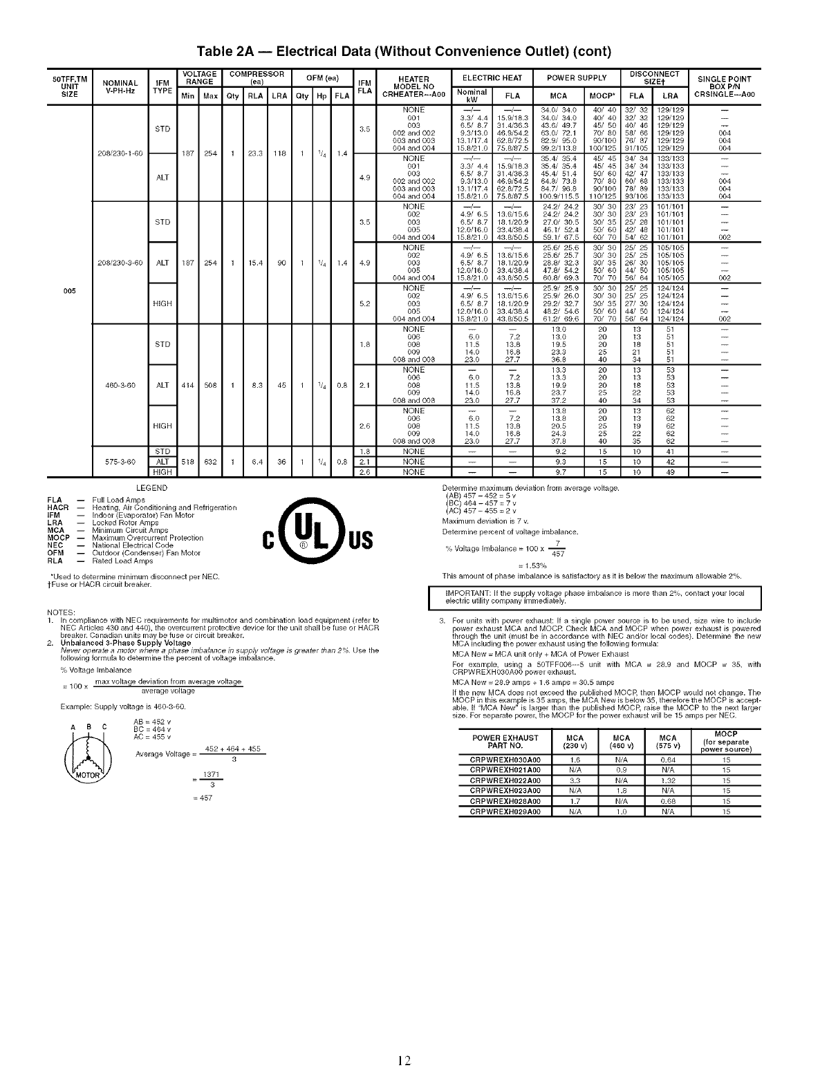
Table 2A -- Electrical Data (Without Convenience Outlet) (cont)
50TFF,TM
UNIT NOMINAL IFM
SIZE V-PH-Hz TYPE
VOLTAGE COMPRESSOR DISCONNECT
HEATER ELECTRIC HEAT POWER SUPPLY SIZE_ SINGLE POINT
RANGE (ea) OFM (ea) IFM MODEL NO BOX PIN
Min Max Qty RLA LRA Qty Hp FLA FLA CRHEATER---A00 Nominal FLA MCA MOCP* FLA LRA CRSINGLE---AO0
kW
208/230-1-60 --
STD 3.5
O05
187 254 1 23.3 118 1 1/4 1.4
ALT 4.9
STD 3.5
208/230-3-60 ALT 187 254 1 15.4 90 1 1/4 1.4 4.9
HIGH 5.2
NONE
001
0O3
002 and 002
003 and 003
004 and 004
NONE
001
003
002 and 002
003 and 003
004 and 004
NONE
002
003
005
004 and 004
NONE
002
003
005
004 and 004
NONE
002
003
005
004 and 004
--/-- --/-- 34.0/ 34.0 40/ 40 32/ 32 129/129
3.3/ 4.4 15.9/18.3 34.0/ 34.0 40/ 40 32/ 32 129/129
6.5/ 8.7 31.4/36.3 43.6/ 49.7 45/ 50 40/ 46 129/129
9.3/13.0 46.9/54.2 63.0/ 72.1 70/ 80 58/ 66 129/129
13.1/17.4 62.8/72.5 82.9/ 95.0 90/100 76/ 87 129/129
15.8/21.0 75.8/87.5 99.2/113.8 100/125 91/105 129/129
--/-- --/-- 35.4/ 35.4 45/ 45 34/ 34 133/133
3.3/ 4.4 15.9/18.3 35.4/ 35.4 45/ 45 34/ 34 133/133
6.5/ 8.7 31.4/36.3 45.4/ 51.4 50/ 60 42/ 47 133/133
9.3/13.0 46.9/54.2 64.8/ 73.8 70/ 80 60/ 68 133/133
13.1/17.4 62.8/72.5 84.7/ 96.8 90/100 78/ 89 133/133
15.8/21.0 75.8/87.5 100.9/115.5 110/125 93/106 133/133
--/-- --/-- 24.2/ 24.2 30/ 30 23/ 23 101/101
4.9/ 6.5 13.6/15.6 24.2/ 24.2 30/ 30 23/ 23 101/101
6.5/ 8.7 18.1/20.9 27.0/ 30.5 30/ 35 25/ 28 101/101
12.0/16.0 38.4/38.4 46.1/ 52.4 50/ 60 42/ 48 101/101
15.8/21.0 43.8/50.5 59.1/ 67.5 60/ 70 54/ 62 101/101
--/-- --/-- 25.6/ 25.6 30/ 30 25/ 25 105/105
4.9/ 6.5 13.6/15.6 25.6/ 25.7 30/ 30 25/ 25 105/105
6.5/ 8.7 18.1/20.9 28.8/ 32.3 30/ 35 26/ 30 105/105
12.0/16.0 38.4/38.4 47.8/ 54.2 50/ 60 44/ 50 105/105
15.8/21.0 43.8/50.5 60.8/ 69.3 70/ 70 56/ 64 105/105
--/-- --/-- 25.9/ 25.9 30/ 30 25/ 25 124/124
4.9/ 6.5 13.6/15.6 25.9/ 26.0 30/ 30 25/ 25 124/124
6.51 8.7 18.1/20.9 29.2/ 32.7 30/ 35 27/ 30 124/124
12.0/16.0 33.4/38.4 48.2/ 54.6 50/ 60 44/ 50 124/124
15.8/21.0 43.8/50.5 61.2/ 69.6 70/ 70 56/ 64 124/124
STD
460-3-60 ALT 414 508 1
HIGH
STD
575-3-60 ALT 518 632 1
HiGH
NONE -- -- 13.0 20 13
006 6.0 7.2 13.0 20 13
1.8 008 11.5 13.8 19.5 20 18
009 14.0 16.8 23.3 25 21
008 and 008 23.0 27.7 36.8 40 34
NONE -- -- 13.3 20 13
006 6.0 7.2 13.3 20 13
8.3 45 1 1/4 0.8 2.1 008 11.5 13.8 19.9 20 18
009 14.0 16.8 23.7 25 22
008 and 008 23.0 27.7 37.2 40 34
NONE -- -- 13.8 20 13
006 6.0 7.2 13.8 20 13
2.6 008 11.5 13.8 20.5 25 19
009 14.0 16.8 24.3 25 22
008 and 008 23.0 27.7 37.8 40 35
1.8 NONE -- -- 9.2 15 10
6.4 36 1 1/4 0.8 2.1 NONE -- -- 9.3 15 10
2.6 NONE -- -- 9.7 15 10
51
51
51
51
51
53
53
53
53
53
62
62
62
62
62
41
42
49
004
004
004
004
004
004
002
002
OO2
LEGEND
FLA -- Full LoadAmps
HACR -- Heating, Air Conditioning and Refrigeration
IFM -- Indoor (Evaporator) Fan Motor
LRA -- Locked Rotor Amps
MCA -- Minimum CircuitAmps
MOCP -- Maximum Overcurrent Protection
NEC -- National Electrical Code
OFM -- Outdoor (Condenser) Fan Motor
RLA -- Rated Load Amps
*Used to determine minimum disconnect per NEC.
tFuse or HACR circuit breaker.
0 us
NOTES:
1. In compliance with NEC requirements for multimotor and combination load equipment (refer to
NEC Articles 430 and 440), the overcurrent protective device for the unit shall be fuse or HACR
breaker. Canadian units may be fuse or circuit breaker.
2. Unbalanced 3-Phase Supply Voltage
Never operate a motor where a phase imbalance in supply voltage is greater than 2% Use the
following formula to determine the percent of voltage imbalance.
% Voltage Imbalance
= 100 x max voltage deviation from average voltage
average voltage
Example: Supply voltage is 460-3-60.
AB = 452 v
AB C BC = 464v
AC = 455 v
Average Voltage = 452 + 464 + 455
3
1371
3
= 457
Determine maximum deviation from average voltage.
(AB) 457 - 452 = 5 v
(BC) 464 - 457 = 7 v
(AC) 457 - 455 = 2 v
Maximum deviation is 7 v.
Determine percent of voltage imbalance.
7
% Voltage Imbalance = 100 x --
457
= 1.53%
This amount of phase imbalance is satisfactory as it is below the maximunl allowable 2%.
I IMPORTANT: If the supply voltage phase imbalance is more than 2%, contact your local I
electric utility company immediately. I
3. For units with power exhaust: If a single power source is to be used, size wire to include
power exhaust MCA and MOCR Check MCA and MOCP when power exhaust is powered
through the unit (must be in accordance with NEC and/or local codes). Determine the new
MCA including the power exhaust using the following formula:
MCA New = MCA unit only + MCA of Power Exhaust
For example, using a 50TFFO06--5 unit with MCA = 28.9 and MOCP = 35, with
CRPWREXHO3OAO0 power exhaust.
MCA New = 28.9 amps + 1.6 amps = 30.5 amps
If the new MCA does not exceed the published MOCP, then MOCP would not change. The
MOCP in this example is 35 amps, the MCA New is below 35, therefore the MOCP is accept-
able. If "MCA New" is larger than the published MOCP, raise the MOCP to the next larger
size. For separate power, the MOCP for the power exhaust will be 15 amps per NEC.
MOCP
POWER EXHAUST MCA MCA MCA (for separate
PART NO. (230 v) (460 v) (575 v) power source)
CRPWREXHO3OAO0 1.6 N/A 0.64 15
CRPWREXHO21AO0 N/A 0.9 N/A 15
CRPWREXHO22AO0 3.3 N/A 1.32 15
CRPWREXHO23AO0 N/A 1.8 N/A 15
CRPWREXHO28AO0 1.7 N/A 0.68 15
CRPWREXHO29AOO N/A 1.0 N/A 15
12
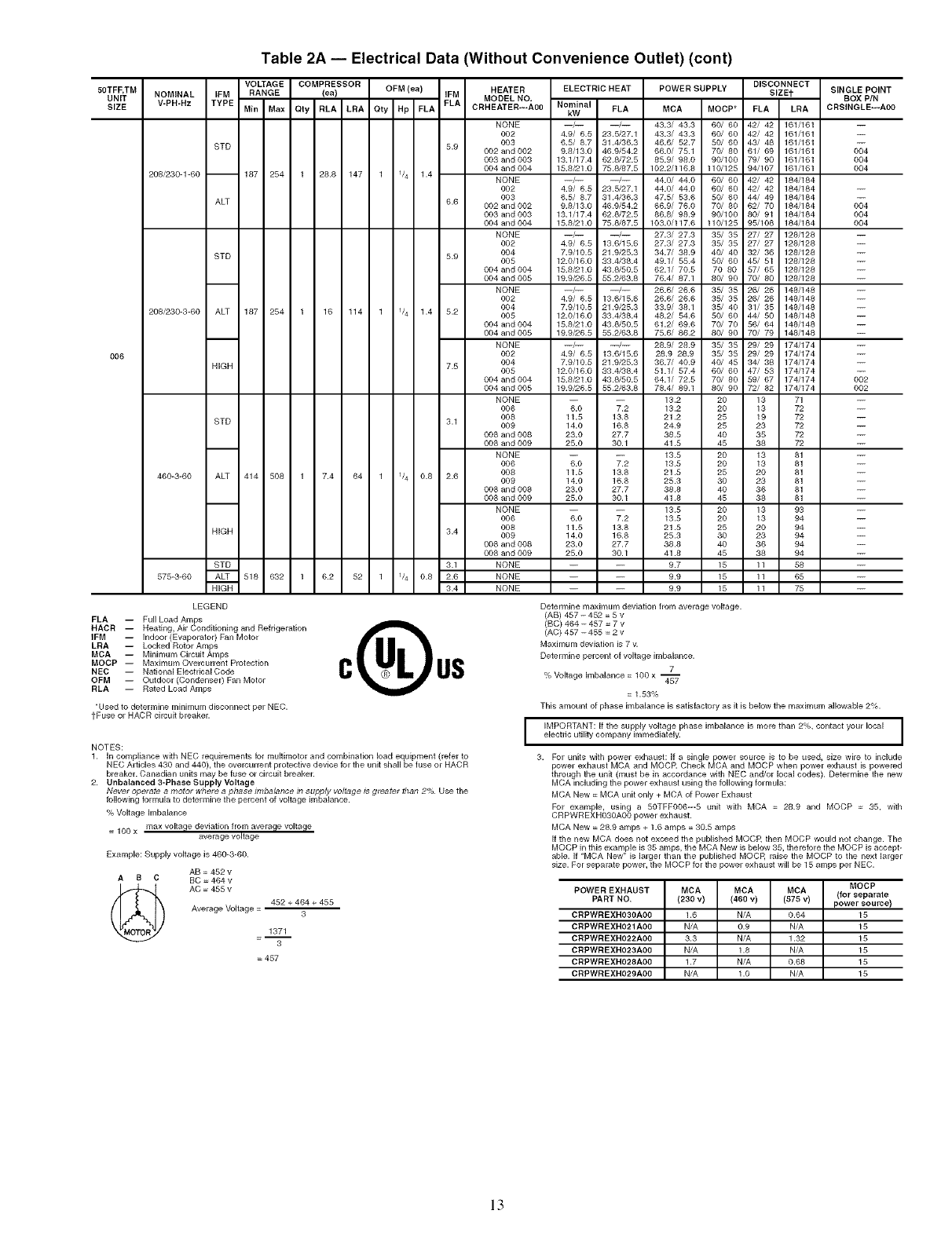
Table 2A -- Electrical Data (Without Convenience Outlet) (cent)
5OTFF,TM
UNIT NOMINAL
SIZE V-PH-Hz
VOLTAGE COMPRESSOR HEATER ELECTRIC HEAT
IFM RANGE (ea) OFM (ea) IFM MODEL NO,
TYPE Min Max Qty RLA LRA Qty Hp FLA FLA CRHEATER---A00 Nominal FLA
STD
208/230-1-60 -- 187 254 1 28.8 147 1 1/4 1.4
NONE
OO2
O03
5.9 002 and 002
003 and 003
004 and 004
NONE
OO2
OO3
6.6 002 and 002
003 and 003
004 and 004
NONE
0O2
5.9 004
005
004 and 004
004 and 005
NONE
OO2
O04
OO5
004 and 004
004 and 005
NONE
OO2
7.5 004
005
004 and 004
004 and 005
NONE
O06
OO8
3.1 009
008 and 008
008 and 009
NONE
O06
OO8
O09
008 and 008
008 and 009
NONE
O06
3.4 008
009
008 and 008
008 and 009
NONE
NONE
NONE
006
ALT
16 114 1 1/4 1.4 5.2
STD
208/230-3-60 ALT 187 254 1
HIGH
7.4 64 1 1/4 0.8 2.6
3.1
6.2 52 1 1/4 0.8 2.6
3.4
kW
--/-- --/-- 43.3/ 43.3 60/ 60 42/ 42 161/161
4.9/ 6.5 23.5/27.1 43.3/ 43.3 60/ 60 42/ 42 161/161
6.5/ 8.7 31.4/36.3 46.6/ 52.7 50/ 60 43/ 48 161/161
9.8/13.0 46.9/54.2 66.0/ 75.1 70/ 80 61/ 69 161/161
13.1/17.4 62.8/72.5 85.9/ 98.0 90/100 79/ 90 161/161
15.8/21.0 75.8/87.5 102.2/116.8 110/125 94/107 161/161
--/-- --/-- 44.0/ 44.0 60/ 60 42/ 42 184/184
4.9/ 6.5 23.5/27.1 44.0/ 44.0 60] 60 42/ 42 184/184
6.5/ 8.7 31.4/36.3 47.5/ 53.6 50/ 60 44/ 49 184/184
9.8/13.0 46.9/54.2 66.9/ 76.0 70) 80 62/ 70 184/184
13.1/17.4 62.8/72.5 86.8/ 98.9 90/100 80/ 91 184/184
15.8/21.0 75.8/87.5 103.0/117.6 110/125 95/108 184/184
--/-- --/-- 27.3/ 27.3 35/ 35 27/ 27 128/128
4.9/ 6.5 13.6/15.6 27.3/ 27.3 35/ 35 27/ 27 128/128
7.9/10.5 21.9/25.3 34.7/ 38.9 40/ 40 32/ 36 128/128
12.0/16.0 33.4/38.4 49.1/ 55.4 50/ 60 45/ 51 128/128
15.8/21.0 43.8/50.5 62.1/ 70.5 70 80 57/ 65 128/128
19.9/26.5 55.2/63.8 76.4/ 87.1 80/ 90 70/ 80 128/128
--/-- --/-- 26.6/ 26.6 35/ 35 26/ 26 148/148
4.9/ 6.5 13.6/15.6 26.6/ 26.6 35/ 35 26/ 26 148/148
7.9/10.5 21.9/25.3 33.9/ 38.1 35/ 40 31/ 35 148/148
12.0/16.0 33.4/38.4 48.2/ 54.6 50/ 60 44/ 50 148/148
15.8/21.0 43.8/50.5 61.2/ 69.6 70/ 70 56/ 64 148/148
19.9/26.5 55.2/63.8 75.6/ 86.2 80/ 90 70/ 79 148/148
--/-- --/-- 28.9/ 28.9 35/ 35 29/ 29 174/174
4.9/ 6.5 13.6/15.6 28.9 28.9 35/ 35 29/ 29 174/174
7.9/10.5 21.9/25.3 36.7/ 40.9 40] 45 34/ 38 174/174
12.0/16.0 33.4/38.4 51.1/ 57.4 60t 60 47/ 53 174/174
15.8/21.0 43.8/50.5 64.1/ 72.5 70/ 80 59/ 67 174/174
19.9/26.5 55.2/63.8 78.4/ 89.1 80/ 90 72/ 82 174/174
-- -- 13.2 20 13
6.0 7.2 13.2 20 13
11.5 13.8 21.2 25 19
14.0 16.8 24.9 25 23
23.0 27.7 38.5 40 35
25.0 30.1 41.5 45 38
-- -- 13.5 20 13
6.0 7.2 18.5 20 13
11.5 13.8 21.5 25 20
14.0 16.8 25.3 30 23
23.0 27.7 38.8 40 36
25.0 30.1 41.8 45 38
-- -- 13.5 20 13
6.0 7.2 13.5 20 13
11.5 13.8 21.5 25 20
14.0 16.8 25.3 30 23
23.0 27.7 38.8 40 36
25.0 30.1 41.8 45 38
-- -- 9.7 15 11
-- -- 9.9 15 11
-- -- 9.9 15 11
POWERSUPPLV DISCONNECT
SlZEt SINGLE POINT
BOX _N
MCA MOCP* FLA LRA CRSINGLE---AOO
STD
460-3-60 ALT 414 508 1
HIGH
STD
575-3-60 ALT 518 632 1
HIGH
LEGEND
FLA -- Full Load Amps
HACR -- Heating, Air Conditioning and Refrigeration
IFM -- Indoor (Evaporator) Fan Motor
LRA -- Locked Rotor Amps
MCA -- Minimum Circuit Amps
MOCP -- Maximum Overcurrent Protection
NEC -- National ElectricaICode
OFM -- Outdoor (Condenser) Fan Motor
RLA -- Rated Load Amps
*Used to determine Ininknum disconnect per NEC.
tPuse or HACR circuit breaker.
71
72
72
72
72
72
81
81
81
81
81
81
93
94
94
94
94
94
58
65
75
004
004
004
NOTES:
1. In compliance with NEC requirements for multimotor and combination load equipment (refer to
NEC Articles 430 and 448}, the overcurrent protective device for the unit shall be fuse or HACR
breaker. Canadian units may be fuse or circuit breaker.
2. Unbalanced 3-Phase Supply Voltage
Never operate a motor where a phase imbalance in supply voltage ts greater than 2% Use the
following formula to determine the percent of voltage imbalance.
% Voltage hnbalance
= 100 x max voltage deviation from average voltage
average voltage
Example: Supply voltage is 460-3-60.
AB = 452 v
AS C BC = 464 v
(_ AC = 455 v 452 + 464 + 455
Average Voltage = 3
1371
3
= 457
004
004
004
002
002
Determine maximum deviation from average voltage.
(AB) 457 -452 = 5 v
(BC) 464 - 457 = 7 v
(AC) 457 -455 = 2 v
Maxhnum deviation is 7 v.
Determine percent of voltage imbalance.
7
% Voltage Imbalance = 100 x --457
= 1.53%
This amount of phase imbalance is satisfactory as it is below the maximum allowable 2%.
I IMPORTANT: If the supply voltage phase imbalance is more than 2%, contact your local I
electric utility company immediately. I
3. For units with power exhaust: If a single power source is to be used, size wire to include
power exhaust MCA and MQCR Check MCA and MQCP when power exhaust is powered
through the unit (must be in accordance with NEC and/or local codes). Determine the new
MCA including the power exhaust using the following formula:
MCA New = MCA unit only + MCA of Power Exhaust
For example, using a 50TFFO06--5 unit with MCA = 28.9 and MOCP = 35, with
CRPWREXHO3OAO0 power exhaust.
MCA New = 28.9 amps + 1.6 amps = 30.5 amps
If the new MCA does not exceed the published MOCR then MOCP would not change. The
MOCP in this example is 35 amps, the MCA New is below 35, therefore the MQCP is accept-
able. If "MCA New" is larger than the published MOCR raise the MOCP to the next larger
size. For separate power, the MQCP for the power exhaust will be 15 amps per NEC.
MOCP
POWER EXHAUST MCA MCA MCA (for separate
PART NO. (230 v) (460 v) (875 v) power source)
CRPWREXHO3OAOO 1.6 N/A 0.64 15
CRPWREXHO21AOO N/A 0.9 N/A 15
CRPWREXHO22AOO 3.3 N/A 1.32 15
CRPWREXHO23AOO N/A 1.8 N/A 15
CRPWREXHO28AOO 1.7 N/A 0.68 15
CRPWREXHO29AOO N/A 1.o N/A 15
13
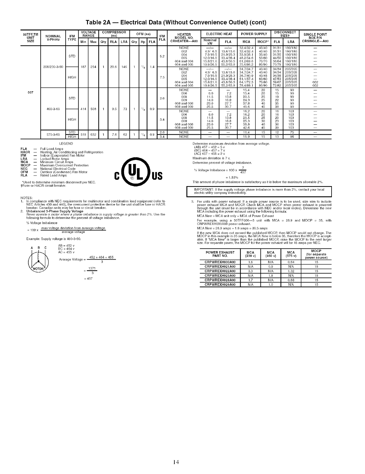
Table 2A -- Electrical Data (Without Convenience Outlet) (cont)
50TFF, TM
UNIT
SIZE
OO7
NOMINAL IFM
V-PH-Hz TYPE
208/230-3-60 --
STD
HIGH
STD
VOLTAGE COMPRESSOR HEATER
RANGE (ea) OFM (ea) IFM MODEL NO
Min Max Qty RLA LRA Oty Hp FLA FLA CRHEATER---A00
187 254 1 20.6 146 1 1/4 1.4
460-3-60 -- 414 508 1
HIGH
STD
575-3-60 _ 518 632 1
LEGEND
FLA -- Full Load Amps
HACR -- Heating, Air Conditioning and Refrigeration
IFM -- Indoor (Evaporator) Fan Motor
LRA -- Locked Rotor Amlpss
MCA Minimum Circuit Amps
MOCP -- Maximum Overcurrent Protection
NEC -- National Electrical Code
OFM -- Outdoor (Condenser) Fan Motor
RLA -- Rated Load Amps
_Used to determine minimum disconnect per NEC.
tFuse or HACR circuit breaker.
NOTES:
9.5 73 1 1/4 0.9
7.6 62 1 1/4 0.9
NONE
002
5.2 004
005
004 and 004
004 and 005
NONE
002
004
7.5 005
004 and 004
004 and 005
NONE
006
2.8 008
009
008 and 008
008 and 009
NONE
006
008
3.4 009
008 and 008
008 and 009
2.6 NONE
3.4 NONE
ELECTRIC HEAT POWER SUPPLY DISCONNECT
SIZEt
Nominal FLA MCA MOCP* FLA LRA
kW
--/-- --/-- 32.4/32.4 40/40 31/31 180/180
4.9/ 6.5 13.6/15.6 32.4/32.4 40/40 31/31 180/180
7.9/10.5 21.9/25.3 33.9/38.1 35/40 31/35 180/180
12.0/16.0 33.4/38.4 48.2/54.6 50/60 44/50 180/180
15.8/21.0 43.8/50.5 61.2/69.6 70/70 56/64 180/180
19.9/26.5 55.2/63.8 75.6/86.2 80/90 70/79 180/180
--/-- --/-- 34.7/34.7 40/40 34/34 205/205
4.9/ 6.5 13.6/15.6 34.7/34.7 40/40 34/34 205/205
7.9/10.5 21.9/25.3 36.7/40.9 40/45 34/38 205/205
12.0/16.0 33.4/38.4 51.1/57.4 60/60 47/53 205/205
15.8/21.0 43.8/50.5 64.1/72.5 70/80 59/67 205/205
19.9/26.5 55.2/63.8 78.4/89.1 80/90 72/82 205/205
-- -- 15.4 20 15 90
6.0 7.2 15.4 20 15 90
11.5 13.5 20.5 25 19 90
14.0 16.8 24.3 25 22 90
23.0 27.7 37.8 40 35 90
25.5 30.7 41.6 45 38 90
-- -- 16.2 20 16 103
6.0 7.2 16.2 20 16 103
11.5 13.8 21.5 25 20 103
14.0 16.8 25.3 30 23 103
23.0 27.7 38.8 40 36 103
25.5 30.7 42.6 45 39 103
-- -- 11.4 15 12 75
-- -- 11.9 15 13 86
SINGLE POINT
BOX PIN
CRSINGLE---AO0
002
002
1. In compliance with NEC requirements for multimotor and combination load equipment (refer to
NEC Articles 430 and 440), the overcurrent protective device for the unit shall be fuse or HACR
breaker. Canadian units may be fuse or circuit breaker.
2. Unbalanced 3-Phase Supply Voltage
Never operate amotor where aphase imbalance in supply voltage is greater than 2% Use the
following formula to determine the percent of voltage imbalance.
% Voltage imbalance
= 100 x max volta[le deviation from average voltage
average voltage
Example: Supply voltage is 460-3-60.
AB = 452 v
AB C BC = 464v
AC = 455 v
Average Voltage = 452 + 464 + 455
3
1371
=-- 3
=457
Determine maximum deviation from average voltage.
(AB) 457 - 452 = 5 v
(BC) 464 - 457 = 7 v
(AC) 457 - 455 = 2 v
Maximum deviation is 7 v.
Determine percent of voltage imbalance.
7
% Voltage imbalance = 100 x 45_
= 1.53%
This amount of phase imbalance is satisfactory as it is below the maximum allowable 2%.
I IMPORTANT: If the supply voltage phase imbalance is more than 2%, contact your local I
electric utility company immediately. I
3. For units with power exhaust: If a single power source is to be used, size wire to include
power exhaust MCA and MOCR Check MCA and MOCP when power exhaust is powered
through the unit (must be in accordance with NEC and/or local codes). Determine the new
MCA including the power exhaust using the following formula:
MCA New = MCA unit only + MCA of Power Exhaust
For example, using a 50TFFO06---5 unit with MCA = 28.9 and MOCP = 35, with
CRPWREXHO3OAO0 power exhaust.
MCA New = 28.9 amps + 1.6 amps = 30.5 amps
If the new MCA does not exceed the published MOCP, then MOCP would not change. The
MOCP in this example is 35 amps, the MCA New is below 35, therefore the MOCP is accept-
able. If "MCA New" is larger than the published MOCP, raise the MOCP to the next larger
size. For separate power, the MOCP for the power exhaust will be 15 amps per NEC.
MOCP
POWER EXHAUST MCA MCA MCA (for separate
PART NO. (230 v) (460 v) (575 v) power source)
CRPWREXHO3OAOO 1.6 N/A 0.64 15
CRPWREXHO21AO0 N/A 0.9 N/A 15
CRPWREXHO22AOO 3.3 N/A 1.32 15
CRPWREXHO23AO0 N/A 1.8 N/A 15
CRPWREXHO28AOO 1.7 N/A 0.68 15
CRPWREXHO20AO0 N/A 1.0 N/A 15
14
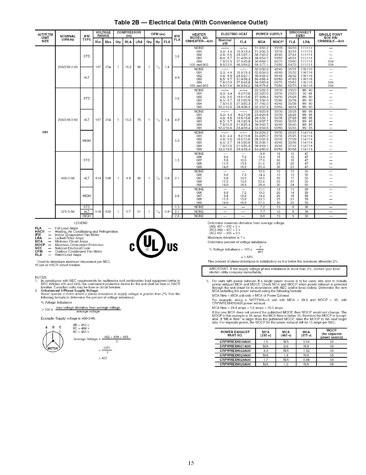
Table 2B -- Electrical Data (With Convenience Outlet)
5OTFF,TM
UNIT
SIZE
004
NOMINAL
V-PH-Hz
208/230-1-60 --
IFM
TYPE
STD
ALT
STD
208/230-3-60 ALT 187 254 1
HIGH
STD
460-3-60 ALT 414 508 1
HIGH
VOLTAGE COMPRESSOR HEATER
RANGE (ea) OFM(ea) IFM MODEL NO,
Min Max Oty RLA LRA Qty Hp FLA FLA CRHEATER---A00
187 254 1 16.2 96 1 1/4 1.4
10.2 75 1 1/4 1.4 4.9
4.4 40 1 1/4 0.8 2.1
NONE
001
3.5 002
003
004
002 and 002
NONE
O01
OO2
4.9 003
OO4
002 and 002
NONE
O01
3.5 002
0O3
004
OO5
NONE
O01
OO2
OO3
O04
OO5
NONE
O01
5.2 002
OO3
004
OO5
NONE
OO6
1.3 007
008
OO9
NONE
OO6
OO7
008
OO9
NONE
OO6
2.6 007
0O8
OO9
NONE
NONE
NONE
STD 1.3
575-3-60 ALT 518 632 1 3.7 31 1 1/4 0.8 2.1
HIGH 2.6
LEGEND
FLA -- Full Load Amps
HACk -- Heating, Air Conditioning and Refrigeration
IFM -- Indoor (Evaporator) Fan Motor
LRA -- Locked Rotor Amps
MCA -- Minimum Circuit Amps
MOCP -- Maximum Overcurrent Protection
NEC -- National ElectriealCode
OFM -- Outdoor (Condenser) Fan Motor
RLA -- Rated Load Amps
*Used to determine minimum disconnect per NEC.
tEuse or HACR circuit breaker.
ELECTRIC HEAT POWER SUPPLY DISCONNECT
SIZEt
Nominal FLA MCA MOCP* FLA LRA
kW
--/-- --/-- 31.2/31.2 35/35 30/30 111/111
3.3/ 4.4 15.9/18.3 31.2/32.3 35/35 30/31 111/111
4.9/ 6.5 23.5/27.1 38.7/43.2 40/45 37/41 111/111
6.4/ 8.7 31.4/36.3 48.6/54.7 50/60 46/51 111/111
7.9/10.5 37.9/43.8 56.8/64.1 60/70 53/60 111/111
9.8/13.0 46.9/54.2 68.0/77.1 70/80 64/72 111/111
--/-- --/-- 32.6/32.6 40/40 31/31 116/116
3.3/ 4.4 15.9/18.3 32.6/34.0 40/40 31/32 116/116
4.9/ 6.5 23.5/27.1 40.5/45.0 45/45 38/42 116/116
6.5/ 8.7 31.4/36.3 50.4/56.4 60/60 47/53 116/116
7.9/10.5 37.9/43.8 58.5/65.8 60/70 55/61 116/116
9.8/13.0 46.9/54.2 69.8/78.8 70/80 65/73 116/116
--/-- --/-- 22.5/22.5 30/30 23/23 90/ 90
3.3/ 4.4 9.2/10.6 22.5/23.0 30/30 23/23 90 90
4.9/ 6.5 13.6/15.6 27.3/29.4 30/30 25/28 90/ 90
6.5/ 8.7 18.1/20.9 33.1/36.0 35/40 30/34 90/ 90
7.9/10.5 21.9/25.3 37.7/42.0 40/45 35/39 90/ 90
12.2/16.0 33.4/38.4 52.1/57.9 60/60 48/54 90/ 90
--/-- --/-- 23.9/23.9 30/30 25/25 95/ 95
3.3/ 4.4 9.2/10.6 23.9/24.8 30/30 25/25 95/ 95
4.9/ 6.5 13.6/15.6 29.1/31.1 30/35 27/29 95/ 95
6.5/ 8.7 18.1/20.9 34.8/37.7 35/40 32/35 95/ 95
7.9/10.5 21.9/25.3 39.5/43.7 40/45 36/40 95/ 95
12.3/16.0 33.4/38.4 53.8/59.6 60/60 50/55 95/ 95
--/-- --/-- 24.2/24.2 30/30 25/25 114/114
3.3/ 4.4 9.2/10.6 24.2/25.2 30/30 25/25 114/114
4.9/ 6.5 13.6/15.6 29.5/31.5 35/35 27/29 114/114
6.5/ 8.7 18.1/20.9 35.2/38.1 40/40 32/36 114/114
7.9/10.5 21.9/25.3 39.9/44.1 40/45 37/41 114/114
12.3/16.0 33.4/38.4 54.2/60.0 60/60 50/56 114/114
-- -- 9.8 15 10 47
6.0 7.2 13.4 15 12 47
8.8 10.6 17.6 20 16 47
11.5 13.8 21.6 25 20 47
14.0 16.8 25.4 30 23 47
-- -- 10.6 15 11 50
6.0 7.2 14.4 15 13 50
8.8 10.6 18.6 20 17 50
11.5 13.8 22.6 25 21 50
14.0 16.8 26.4 30 24 50
-- -- 11.1 15 11 59
6.0 7.2 15.0 20 14 59
8.8 10.6 19.2 20 18 59
11.5 13.8 23.3 25 21 59
14.0 16.8 27.0 30 25 59
-- -- 7.2 15 8 36
-- -- 7.7 15 9 39
-- -- 8.0 15 9 58
SINGLE POINT
BOX PIN
CRSINGLE---AOO
004
004
004
004
NOTES:
1. In compliance with NEC requirements for multimotor and combination load equipment (refer to
NEC Articles 430 and 440), the overeurrent protective device for the unit shall be fuse or HACR
breaker. Canadian units may be fuse or circuit breaker.
2. Unbalanced 3-Phase Supply Voltage
Never operate a motor where a phase imbalance in supply voltage ts greater than 2% Use the
following formula to determine the percent of voltage imbalance.
% Voltage Imbalance
= lOO x max voltage deviation from average voltage
average voltage
Example: Supply voltage is 460-3-60.
AB = 452 v
AB C BC = 464 v
(_ AC = 455 v
Average Voltage = 452 + 464 + 455
3
1371
3
= 457
Determine maximum deviation from average voltage.
(AB) 457 -452 = 5 v
(BC) 464 - 457 = 7 v
(AC) 457 - 455 = 2 v
Maximum deviation is 7 v.
Determine percent of voltage imbalance.
7
% Voltage Imbalance = 100 x --457
= 1.53%
This amount of phase imbalance is satisfactory as it is below the maximum allowable 2%.
I IMPORTANT: If the supply voltage phase imbalance is more than 2%, contact your local I
electric utility company immediately. I
3. For units with power exhaust: If a single power source is to be used, size wire to include
power exhaust MCA and MQCR Check MCA and MOCP when power exhaust is powered
through the unit (must be in accordance with NEC and/or local codes). Determine the new
MCA including the power exhaust using the following formula:
MCA New = MCA unit only + MCA of Power Exhaust
For example, using a 50TFFOO6--5 unit with MCA = 28.9 and MOCP = 35, with
CRPWREXHO3OAO0 power exhaust.
MCA New = 28.9 amps + 1.6 amps = 30.5 amps
If the new MCA does not exceed the published MOCk then MOCP would not change. The
MOCP in this example is 35 amps, the MCA New is below 35, therefore the MOCP is accept-
able. If "MCA New" is larger than the published MOCP, raise the MOCP to the next larger
size. For separate power, the MOCP for the power exhaust will be 15 amps per NEC.
MOCP
POWER EXHAUST MCA MCA MCA (for separate
PART NO. (230 v) (460 v) (575 v) power source) /
CRPWREXHO3OA00 1.6 N/A 0.54 15
CRPWREXH021AO0 N/A 0.9 N/A 15
CRPWREXHO22A00 3.3 N/A 1.32 15
CRPWREXHO23AOO N/A 1.8 N/A 15
CRPWREXHO28AOO 1.7 N/A 0.68 15
CRPWREXHO29AOO N/A 1.O N/A 15
1.5
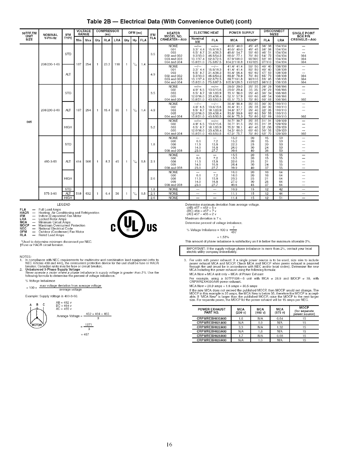
Table 2B -- Electrical Data (With Convenience Outlet) (cont)
50TFF,TM
UNIT NOMINAL IFM
SIZE V-PH-Hz TYPE
STD
VOLTAGE COMPRESSOR
RANGE (ea) OFM (ea)
Min Max Qty RLA LRA Qty Hp FLA
208/230-1-60 -- 187 254 1 23.3 118 1 1/4 1.4
ALT
STD
ALT 197208/230-3-60
005
HIGH
STD
254 1 15.4 90 1 1/4 1.4
460-3-69 ALT 414 508 1 8.3 45 1 1/4 9.9
HiGH
STD
575-3-69 ALT 518 632 1
HIGH
HEATER ELECTRIC HEAT POWER SUPPLY
IFM MODEL NO
FLA CRHEATER---A00 Nominal FLA MCA MOCP*
kW
NONE --/-- --/-- 40.0/ 40.0 45/ 45
001 3.3/ 4.4 15.9/18.3 40.0/ 40.0 45/ 45
003 6.5/ 8.7 31.4/36.3 48.6/ 54.7 50/ 60
3.5 002 and 002 9.3/13.0 46.9/54.2 68.0/ 77.1 70/ 80
OO3 and 003 13.1/17.4 62.8/72.5 97.9/100.0 90/100
OO4 and 004 15.8/21.0 75.8/87.5 104.2/118.8 110/125
NONE --/-- --/-- 41.4/ 41.4 50/ 50
001 3.3/ 4.4 15.9/18.3 41.4/ 41.4 50/ 50
003 6.5/ 8.7 31.4/36.3 50.4/ 56.4 8(i)/ 80
4.9 002 and 002 9.3/13.0 46.9/54.2 69.8/ 78.8 70/ 80
OO3 and 003 13.1/17.4 62.8/72.5 89.7/101.8 90/110
OO4 and 004 15.8/21.0 75.8/97.5 105.9/120.5 110/125
NONE --/-- --/-- 29.0/ 29.0 35/ 35
002 4.9/ 6.5 13.6/15.6 29.0/ 29.4 35 35
3.5 003 6.5/ 8.7 18.1/20.9 33.1/ 36.0 35/ 40
005 12.0/16.0 33.4/36.4 52.1/ 57.9 60/ 60
OO4andOO4 15.8/21.0 43.8/50.5 65.1/ 73.5 70/ 80
NONE --/-- --/-- 30.4/ 30.4 35/ 35
002 4.9/ 6.5 13.6/15.6 30.4/ 31.1 35/ 35
4.9 003 6.5/ 8.7 19.1/20.9 34.8/ 37.7 35/ 40
005 12.0/16.0 33.4/36.4 53.8/ 59.6 60/ 60
004 and 004 15.8/21.0 43.8/50.5 66.9/ 75.3 70/ 80
NONE --/-- --/-- 30.7/ 30.7 35/ 35
002 4.9/ 6.5 13.6/15.6 30.7/ 31.5 35/ 35
5.2 003 6.5/ 8.7 18.1/20.9 35.2/ 38.1 40/ 40
005 12.0/16.0 33.4/38.4 54.2/ 60.0 60/ 60
004 and 004 15.8/21.0 43.8/50.5 67.2/ 75.7 70/ 80
NONE -- -- 15.2 20
006 6.0 7.2 15.2 20
1.8 008 11.5 13.8 22.3 25
009 14.0 16.8 26.0 30
008 and 008 23.0 27.7 39.6 40
NONE -- -- 15.5 20
006 6.0 7.2 15.5 20
2.1 008 11.5 13.8 22.6 25
009 14.0 16.8 26.4 30
008 and 008 23.0 27.7 39.9 40
NONE -- -- 16.0 20
006 6.0 7.2 16.0 20
2.6 008 11.5 13.8 23.3 25
009 14.0 16.8 27.0 30
008 and 008 23.0 27.7 40.6 45
1.8 NONE -- -- 10.9 15
2.1 NONE -- -- 11.1 15
2.6 NONE -- -- 11.4 15
LEGEND
FLA -- Full LoadAmps
HACR -- Heating, Air Conditioning and Refrigeration
IFM -- Indoor (Evaporator) Fan Motor
LRA -- Locked Rotor Amps
MCA -- Minimum CircuitAmps
MOCP -- Maximum Overcurrent Protection
NEC -- National Electrical Code
OFM -- Outdoor (Condenser) Fan Motor
RLA -- Rated Load Amps
*Used to determine mhgmum disconnect per NEC.
tFuse or HACR circuit breaker.
6.4 36 1 1/4 0.9
DISCONNECT
SlZEf SINGLE POINT
BOX PIN
FLA LRA CRSINGLE---AOO
38/ 38 134/134
38/ 38 134/134
46/ 51 134/134
64/ 72 134/134 004
82/ 93 134/134 004
97/110 134/134 004
40/ 40 138/138
40/ 40 138/138
47/ 53 138/138
65/ 73 138/138 004
83/ 95 138/138 004
98/112 138/138 004
29/ 29 106/106
29/ 29 106/106
30/ 34 106/106
48/ 54 106/106
60/ 68 106/106 002
30/ 30 110/110
30/ 30 110/110
32/ 35 110/110
50/ 55 110/110
62/ 69 110/110 002
31/ 31 129/129
31/ 31 129/129
32 /36 129/129
50/ 56 129/129
62/ 70 129/129 002
15 53 --
15 53 --
20 53 --
24 53 --
36 53 --
15 55 --
15 55 --
21 55 --
24 55 --
37 55 --
16 64 --
16 64 --
21 64 --
25 64 --
37 64 --
12 42 --
12 44 --
12 51 --
NOTES:
1. In compliance with NEC requirements for multimotor and combination load equipment (refer to
NEC Articles 430 and 440), the overcurrent protective device for the unit shall be fuse or HACR
breaker. Canadian units may be fuse or circuit breaker.
2. Unbalanced 3-Phase Supply Voltage
Never operate a motor where a phase imbafance in supply vo/tage is greater than 2% Use the
following formula to determine the percent of voltage imbalance.
% Voltage Imbalance
=100 x max voltage deviation from average voltage
average voltage
Example: Supply voltage is 460-3-60.
AB = 452 v
AB C BC =464v
_) AC =455 v
Average Voltage =452 + 464 + 455
3
1371
3
= 457
I
Determine maximum deviation from average voltage.
(AB) 457 - 452 =5 v
(BC) 464 - 457 = 7 v
(AC) 457 - 455 =2 v
Maximum deviation is 7 v.
Determine percent of voltage imbalance.
7
% Voltage Imbalance = 100 x --
457
= 1.53%
This amount of phase imbalance is satisfactory as it is below the maximunl allowable 2%.
IMPORTANT: If the supply voltage phase imbalance is more than 2%, contact your local I
electric utility company immediately. I
3. For units with power exhaust: If a single power source is to be used, size wire to include
power exhaust MCA and MOCR Check MCA and MOCP when power exhaust is powered
through the unit (must be in accordance with NEC and/or local codes). Determine the new
MCA including the power exhaust using the following formula:
MCA New = MCA unit only + MCA of Power Exhaust
For example, using a 50TFF006---5 unit with MCA = 28.9 and MOCP = 35, with
CRPWREXH039A00 power exhaust.
MCA New = 28.9 amps + 1.6 amps = 30.5 amps
If the new MCA does not exceed the published MOCP, then MOCP would not change. The
MOCP in this example is 35 amps, the MCA New is below 35, therefore the MOCP is accept-
able. If "MCA New" is larger than the published MOCP, raise the MOCP to the next larger
size. For separate power, the MOCP for the power exhaust will be 15 amps per NEC.
MOCP
POWER EXHAUST MCA MCA MCA (for separate
PART NO. (230 v) (460 v) (575 v) power source)
CRPWREXHO3OAOO 1.6 N/A 0.64 15
CRPWREXHO21AOO N/A 0.9 N/A 15
CRPWREXHO22AOO 3.3 N/A 1.32 15
CRPWREXHO23AOO N/A 1.8 N/A 15
CRPWREXHO28AOO 1.7 N/A 0.68 15
CRPWREXHO29AOO N/A 1 .o N/A 15
16
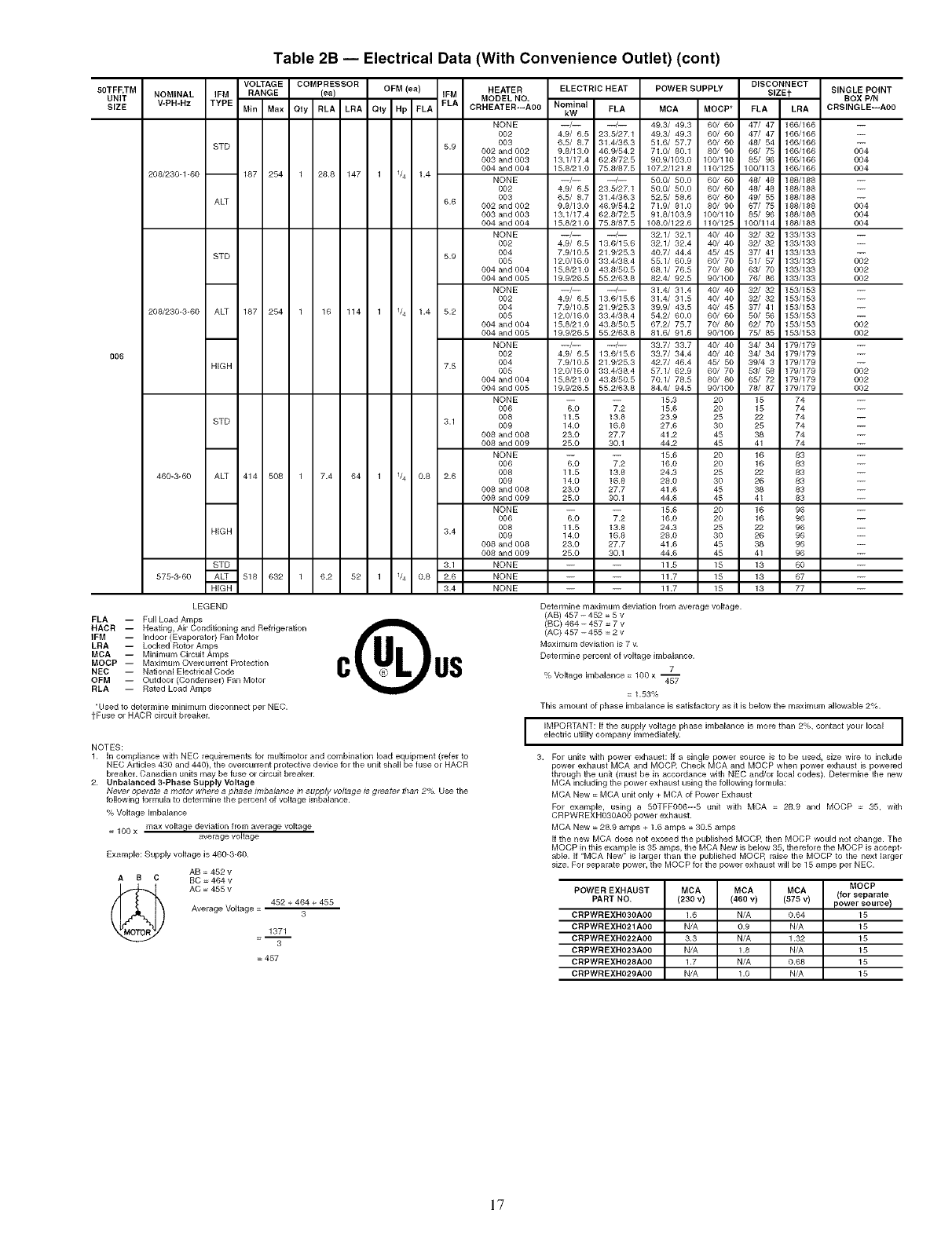
Table 2B -- Electrical Data (With Convenience Outlet) (cont)
80TFF,TM
UNIT NOMINAL IFM
SIZE V-PH-Hz TYPE
208/230-1-60 --
STD
006
ALT
STD
208/230-3-60 ALT 187 254 1
HIGH
VOLTAGE COMPRESSOR HEATER
RANGE (ea) OFM(ea) IFM MODEL NO,
Min Max Qty RLA LRA Qty Hp FLA FLA CRHEATER---A00
187 254 1 28.8 147 1 1/4 1.4
NONE
OO2
OO3
5"9 002 and 002
003 and 003
004 and 004
NONE
OO2
0O3
6.6 002 and 002
003 and 003
004 and 004
NONE
OO2
5.9 004
005
004 and 004
004 and 005
NONE
0O2
OO4
0O5
004 and 004
004 and 005
NONE
OO2
7.5 004
005
004 and 004
004 and 005
16 114 1 1/4 1.4 5.2
STD 3.1
460-3-60 ALT 414 508 1 7.4 64 1 1/4 0.8 2.6
HIGH 3.4
STD 3.1
575-3-60 ALT 518 632 1 6.2 52 1 1/4 0.8 2.6
HIGH 3.4
LEGEND
FLA -- Full Load Amps
HACR -- Heating, Air Conditioning and Refrigeration
IFM -- Indoor (Evaporator) Fall Motor
LRA -- Locked Rotor Amps
MCA -- Minimum Circuit Amps
MOCP -- Maximum Overcurrent Protection
NEC -- National ElectricalCode
OEM -- Outdoor (Condenser) Fan Motor
RLA -- Rated Load Amps
*Used to determine Ininknum disconnect per NEC.
tPuse or HACR circuit breaker.
ELECTRIC HEAT POWER SUPPLY DISCONNECT
SIZEt SINGLE POINT
BOX PIN
Nominal FLA MCA MOCP* FLA LRA CRSINGLE---A00
kW
--/-- --/-- 49.3/ 49.3 60/ 60 47/ 47 166/166
4.9/ 6.5 23.5/27.1 49.3/ 49.3 60/ 60 47/ 47 166/166
6.5/ 8.7 31.4/36.3 51.6/ 57.7 60/ 60 48/ 54 166/186
9.8/13.0 46.9/54.2 71.0/ 80.1 80/ 90 66/ 75 166/166
13.1/17.4 62.8/72.5 90.9/103.0 100/110 85/ 96 166/166
15.8/21.0 75.8/87.5 107.2/121.8 110/125 100/113 166/166
--/-- --/-- 5010/ 50.0 60t 60 48/ 48 188/188
4.9/ 6.5 23.5/27.1 50.0/ 50.0 60/ 60 48/ 48 188/188
6.5/ 8.7 31.4/36.3 52.5/ 58.6 60/ 60 49/ 55 188/188
9.8/13.0 46.9/54.2 71.9/ 81.0 80/ 90 67/ 75 188/188
13.1/17.4 62.8/72.5 91.8/103.9 100/110 85/ 96 188/188
15.8/21.0 75.8/87.5 108.0/122.6 110/125 100/114 188/188
--/-- --/-- 32.1/ 32.1 40/ 40 32/ 32 133/133
4.9/ 6.5 13.6/15.6 32.1/ 32.4 40/ 40 32/ 32 133/133
7.9/10.5 21.9/25.3 40.7/ 44.4 45/ 45 37/ 41 133/133
12.0/16.0 33.4/38.4 55.1/ 60.9 60/ 70 51/ 57 133/133
15.8/21.0 43.8/50.5 68.1/ 76.5 70/ 80 63/ 70 133/133
19.9/26.5 55.2/63.8 82.4/ 92.5 90/100 76/ 86 133/133
--/-- --/-- 31.4/ 31.4 40/ 40 32/ 32 153/153
4.9/ 6.5 13.6/15.6 31.4/ 31.5 40/ 40 32/ 32 153/153
7.9/10.5 21.9/25.3 39.9/ 43.5 40/ 45 37/ 41 153/153
12.0/16.0 33.4/38.4 54.2/ 60.0 60/ 60 50/ 56 153/153
15.8/21.0 43.8/50.5 67.2/ 75.7 70/ 80 62/ 70 153/153
19.9/26.5 55.2/63.8 81.6/ 91.6 90/100 75/ 85 153/153
--/-- --/-- 33.7/ 33.7 40/ 40 34/ 34 179/179
4.9/ 6.5 13.6/15.6 33.7/ 34.4 40/ 40 34/ 34 179/179
7.9/10.5 21.9/25.3 42.7/ 46.4 45/ 50 39/4 3 179/179
12.0/16.0 33.4/38.4 57.1/ 62.9 60/ 70 53/ 58 179/179
15.8/21.0 43.8/50.5 70.1/ 78.5 80/ 80 65/ 72 179/179
19.9/26.5 55.2/63.8 84.4/ 94.5 90/100 78/ 87 179/179
NONE -- -- 15.3 20 15 74
006 6.0 7.2 15.6 20 15 74
008 11.5 13.8 23.9 25 22 74
009 14.0 16.8 27.6 30 25 74
008 and 008 23.0 27.7 41.2 45 38 74
008 and 009 25.0 30.1 44.2 45 41 74
NONE -- -- 15.6 20 16 83
006 6.0 7.2 16.0 20 16 83
008 11.5 13.8 24.3 25 22 83
009 14.0 16.8 28.0 30 26 83
008 and 008 23.0 27.7 41.6 45 38 83
008 and 009 25.0 30.1 44.6 45 41 83
NONE -- -- 15.6 20 16 96
006 6.0 7.2 16.0 20 16 96
008 11.5 13.8 24.3 25 22 98
009 14.0 16.8 28.0 30 26 96
008 and 008 23.0 27.7 41.6 45 38 96
008 and 009 25.0 30.1 44.6 45 41 96
NONE -- -- 11.5 15 13 60
NONE -- -- 11.7 15 13 67
NONE -- -- 11.7 15 13 77
O04
OO4
OO4
O04
O04
O04
OO2
OO2
002
OO2
OO2
OO2
OO2
OO2
c 0s
NOTES:
1. In compliance with NEC requirements for muffimotor and combination load equipment (refer to
NEC Articles 430 and 440), the overcurrent protective device for the unit shall be fuse or HACR
breaker. Canadian units may be fuse or circuit breaker.
2. Unbalanced 3-Phase Supply Voltage
Never operate a motor where a phase imbalance in supply voltage ts greater than 2% Use the
following formula to determine the percent of voltage imbalance.
% Voltage hnbalance
= 100 x max voltage deviation from average voltage
average voltage
Example: Supply voltage is 460-3-60.
AB = 452 v
AS C BC = 464 v
_) AC = 455 v 452 + 464 + 455
Average Voltage = 3
1371
3
= 457
Determine maximum deviation from average voltage.
(AB) 457 -452 = 5 v
(BC) 464 - 457 = 7 v
(AC) 457 -455 = 2 v
Maximum deviation is 7 v.
Determine percent of voltage imbalance.
7
% Voltage Imbalance = 100 x --457
= 1.53%
This amount of phase imbalance is satisfactory as it is below the maximum allowable 2%.
I IMPORTANT: If the supply voltage phase imbalance is more than 2%, contact your local
electric utility company immediately. I
3. For units with power exhaust: If a single power source is to be used, size wire to include
power exhaust MCA and MOCR Check MCA and MOCP when power exhaust is powered
through the unit (must be in accordance with NEC and/or local codes). Determine the new
MCA including the power exhaust using the following formula:
MCA New = MCA unit only + MCA of Power Exhaust
For example, using a 50TFFOO6m5 unit with MCA = 28.9 and MOCP = 35, with
CRPWREXHO3OAO0 power exhaust.
MCA New = 28.9 amps + 1.6 amps = 30.5 amps
If the new MCA does not exceed the published MOCR then MOCP would not change. The
MOCP in this example is 35 amps, the MCA New is below 35, therefore the MOCP is accept-
able. ff "MCA New" is larger than the published M©CP, raise the MOCP to the next larger
size. For separate power, the MOCP for the power exhaust will be 15 amps per NEC.
MOCP
POWER EXHAUST MCA MCA MCA (for separate
PART NO. (230 v) (460 v) (875 v) power source)
CRPWREXH03OA00 1.6 N/A 0.64 15
CRPWREXH021A00 N/A 0.9 N/A 15
CRPWREXH022A00 3.3 N/A 1.32 15
CRPWREXH023A00 N/A 1.8 N/A 15
CRPWREXH028A00 1.7 N/A 0.68 15
CRPWREXH029A00 N/A 1.0 N/A 15
17
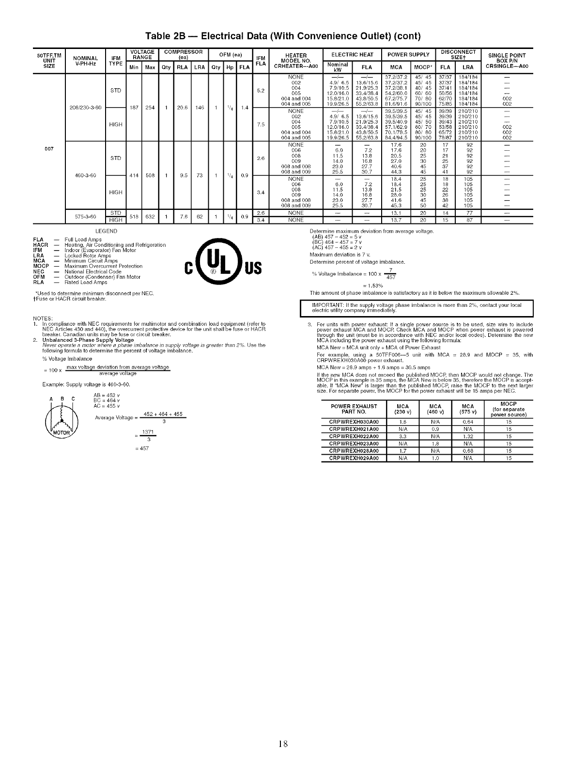
Table 2B -- Electrical Data (With Convenience Outlet) (cont)
50TFF, TM
UNIT
SIZE
OO7
NOMINAL IFM
V-PH-Hz TYPE
208/230-3-60 --
STD
HiGH
STD
VOLTAGE COMPRESSOR
RANGE (ea) OFM (ea)
Min Max Qty RLA LRA Oty Hp FLA
187 254 1 20.6 146 1 1/4 1.4
460-3-60 -- 414 508 1 9.5 73 1 1/4 0.9
HiGH
STD
575-3-60 _ 518 632 1
LEGEND
FLA -- Full Load Amps
HACR -- Heating, Air Conditioning and Refrigeration
IFM -- Indoor (Evaporator) Fan Motor
LRA -- Locked Rotor Amlpss
MCA Minimum Circuit Amps
MOCP -- Maximum Overcurrent Protection
NEC -- National Electrical Code
OFM -- Outdoor (Condenser) Fan Motor
RLA -- Rated Load Amps
_Used to determine minimum disconnect per NEC.
tFuse or HACR circuit breaker.
NOTES:
7.6 62 1 1/4 0.9
HEATER ELECTRIC HEAT POWER SUPPLY
IFM MODEL NO,
FLA CRHEATER---AOO Nominal FLA MCA MOCP*
kW
NONE --/-- --/-- 37.2/37.2 45/ 45
002 4.9/ 6.5 13.6/15.6 37.2/37.2 45/ 45
5.2 004 7.9/10.5 21.9/25.3 37.2/39.1 40/ 45
005 12.0/16.0 33.4/39.4 54.2/60.0 60/ 60
004 and 004 15.8/21.0 43.8/50.5 67.2/75.7 70/ 80
OO4 and OO5 19.9/26.5 55.2/63.8 81.6/91.6 90/100
NONE --/-- --/-- 39.5/39.5 45/ 45
002 4.9/ 6.5 13.6/15.6 39.5/39.5 45/ 45
094 7.9/10.5 21.9/25.3 39.5/49.9 45/ 50
7.5 005 12.0/16.9 33.4/38.4 57.1/62.9 60/ 70
9O4andOO4 15.8/21.0 43.8/50.5 70.1/78.5 80/ 80
904 and 905 19.9/26.5 55.2/63.8 84.4/94.5 90/100
NONE -- -- 17.6 20
006 6.0 7.2 17.6 20
2.6 008 11.5 13.8 20.5 25
009 14.0 16.8 27.0 30
098 and 908 23.0 27.7 49.6 45
008 and 009 25.5 30.7 44.3 45
NONE -- -- 18.4 25
006 6.0 7.2 18.4 25
008 11.5 13.9 21.5 25
3.4 009 14.0 16.8 29.0 30
OO9 and 008 23.0 27.7 41.6 45
008 and 009 25.5 30.7 45.3 50
2.6 NONE -- -- 13.1 20
3.4 NONE -- -- 13.7 20
DISCONNECT
SIZEf SINGLE POINT
BOX PIN
FLA LRA CRSINGLE---AOO
37_7 18_184
37_7 18_184
37/41 18_184
50/56 184/184
62/70 184/184 002
75/85 18_184 002
39_9 21_210
39_9 21_210
39/43 210/210
53/58 210/210 902
65/72 21_210 002
78/87 21_210 002
17 92 --
17 92 --
21 92 --
25 92 --
37 92 --
41 92 --
18 105
18 105
22 105
26 105
38 105
42 105
14 77 --
15 87 --
1. In compliance with NEC requirements for multimotor and combination load equipment (refer to
NEC Articles 430 and 440), the overcurrent protective device for the unit shall be fuse or HACR
breaker. Canadian units may be fuse or circuit breaker.
2. Unbalanced 3-Phase Supply Voltage
Never operate amotor where aphase imbalance in supply voltage is greater than 2% Use the
following formula to determine the percent of voltage imbalance.
% Voltage Imbalance
= 100 x max voltage deviation from average voltage
average voltage
Example: Supply voltage is 460-3-60.
AB = 452 v
AB C BC = 464v
AC = 455 v
Average Voltage = 452 + 464 + 455
3
1371
=-- 3
=457
Determine maximum deviation from average voltage.
(AB) 457 - 452 = 5 v
(BC) 464 - 457 = 7 v
(AC) 457 - 455 = 2 v
Maximum deviation is 7 v.
Determine percent of voltage imbalance.
7
% Voltage Imbalance = 100 x 45_
= 1.53%
This amount of phase imbalance is satisfactory as it is below the maximum allowable 2%.
JIMPORTANT: If the supply voltage phase imbalance is more than 2%, contact your local J
electric utility company immediately. I
3. For units with power exhaust: If a single power source is to be used, size wire to include
power exhaust MCA and MOCR Check MCA and MOCP when power exhaust is powered
through the unit (must be in accordance with NEC and/or local codes). Determine the new
MCA including the power exhaust using the following formula:
MCA New = MCA unit only + MCA of Power Exhaust
For example, using a 50TFFO06---5 unit with MCA = 28.9 and MOCP = 35, with
CRPWREXHO30AO0 power exhaust.
MCA New = 28.9 amps + 1.6 amps = 30.5 amps
if the new MCA does not exceed the published MOCP, then MOCP would not change. The
MOCP in this example is 35 amps, the MCA New is below 35, therefore the MOCP is accept-
able. If "MCA New" is larger than the published MOCP, raise the MOCP to the next larger
size. For separate power, the MOCP for the power exhaust will be 15 amps per NEC.
MOCP
POWER EXHAUST MCA MCA MCA (for separate
PART NO. (230 v) (460 v) (575 v) power source)
CRPWREXHO3OAOO 1.6 N/A 0.64 15
CRPWREXHO21AOO N/A 0.9 N/A 15
CRPWREXHO22AOO 3.3 N/A 1.32 15
CRPWREXHO23AOO N/A 1.8 N/A 15
CRPWREXHO28AOO 1.7 N/A 0.68 15
CRPWREXHO29AOO N/A 1 .o N/A 15
18
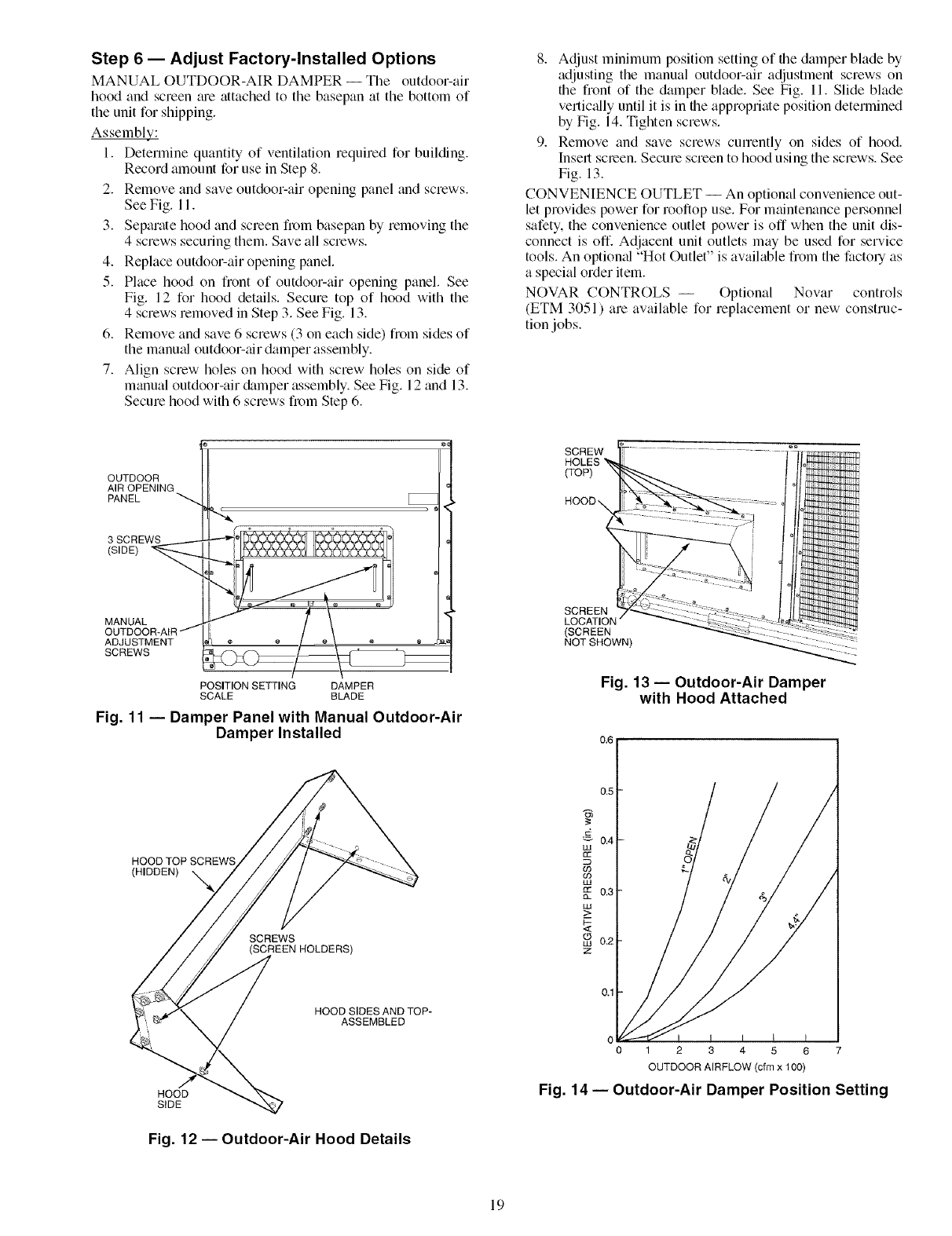
Step 6 -- Adjust Factory-Installed Options
MANUAL OUTDOOR-AIR DAMPER -- The outdoor-air
hood and screen me attached to the basepan at the bottom of
the unit for shipping.
AssemblE;.."
1. Determine quantity of ventilation required for building.
Record amount for use in Step 8.
2. Remove and save outdoor-air opening panel and screws.
See Fig. 11.
3. Separate hood and screen from basepan by removing the
4 screws securing them. Save all screws.
4. Replace outdoor-air opening panel.
5. Place hood on front of outdoor-air opening panel. See
Fig. 12 for hood details. Secure top of hood with the
4 screws removed in Step 3. See Fig. 13.
6. Remove and save 6 screws (3 on each side) fiom sides of
the manu_d outdoor-air damper assembly.
7. Align screw holes on hood with screw holes on side of
manual outdoor-air &tmper assembly. See Fig. 12 and 13.
Secure hood with 6 screws from Step 6.
8. Adjust minimum position setting of the damper blade by
adjusting the manual outdoor-air adjustment screws on
the front of the damper blade. See Fig. 11. Slide blade
vertically until it is in the appropriate position determined
by Fig. 14. Tighten screws.
9. Remove and save screws cunently on sides of hood.
Insert screen. Secure screen to hood using the screws. See
Fig. 13.
CONVENIENCE OUTLET -- An optional convenience out-
let provides power for rooftop use. For maintenance pel_onnel
safety, the convenience outlet power is off when the unit dis-
connect is off. Adjacent unit outlets may be used for service
tools. An optiomfl "Hot Outlet" is available from the factoly as
a special order item.
NOVAR CONTROLS -- Optional Novar controls
(ETM 3051) are available for replacement or new construc-
tion jobs.
OUTDOOR
AIR OPENING
PANEL
3 SCREWS
(SIDE)
MANUAL
OUTDOOR-AIR /
ADJUSTMENT
SCREWS
POSITION SETTING DAMPER
SCALE BLADE
Fig. 11 -- Damper Panel with Manual Outdoor-Air
Damper Installed
HOOD TOP SCREWS
(HIDDEN)
SCREWS
SCREW
HOLES '_
(TOP)
SCREEN
LOCATION
(SCREEN
NOT SHOWN)
Fig. 13 -- Outdoor-Air Damper
with Hood Attached
HOOD SIDES AND TOP-
ASSEMBLED
HOOD
SIDE
Fig. 12- Outdoor-Air Hood Details
C
012345 6 7
OUTDOOR AIRFLOW (cfm x 100)
Fig. 14- Outdoor-Air Damper Position Setting
19
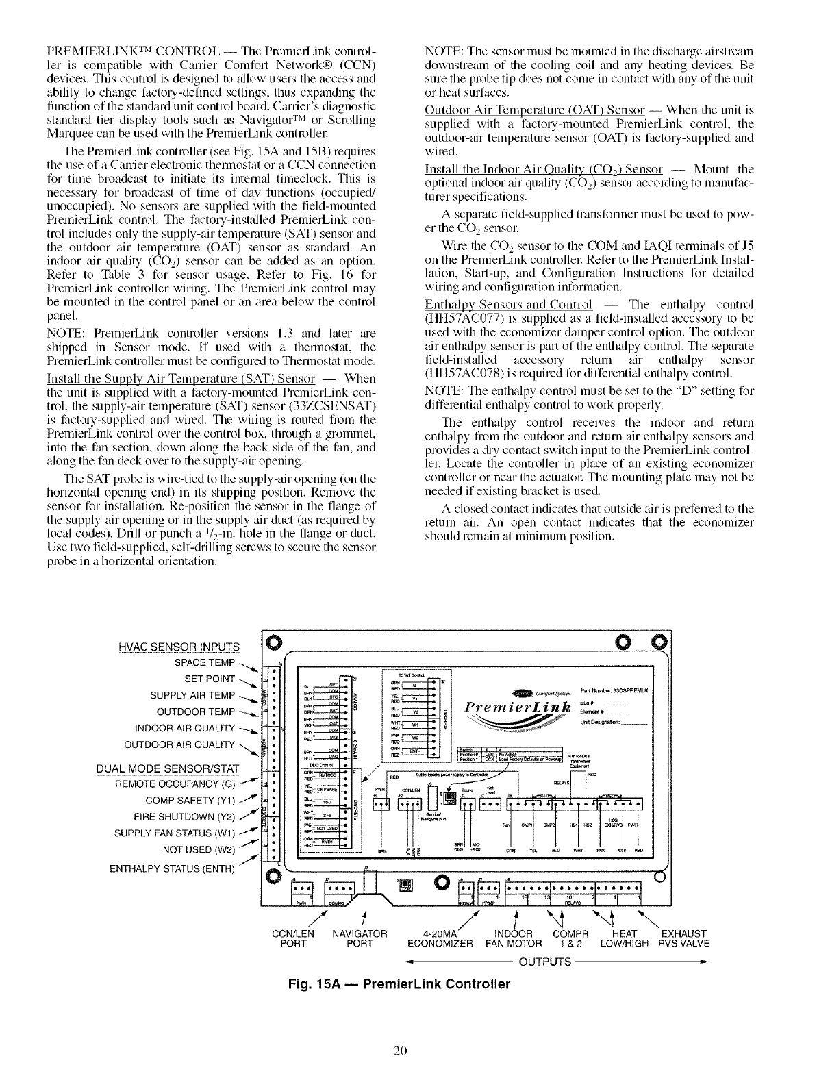
PREMIERLINK rM CONTROL -- Tile PremierLink control-
let is compatible with Career Comfort Network® (CCN)
devices. This control is designed to allow usel5 file access and
ability to change factory-defined settings, thus expanding the
function of the stan&trd unit control board. CmTier's diagnostic
standard tier display tools such as Navigator TM or Scrolling
Marquee can be used with the PremierLink contmfler.
The PremierLink contmfler (see Fig. 15A and 15B) requires
the use of a Canier electronic thermostat or a CCN connection
for time broadcast to initiate its intermfl fimeclock. This is
necessary for broadcast of time of day functions (occupied/
unoccupied). No sensors am supplied wifli the field-mounted
PremierLink control. The factory-installed PmmierLink con-
trol includes only file supply-air temperature (SAT) sensor and
the outdoor air temperature ((-)AT) sensor as standard. An
indoor air qutflity (CO2) sensor can be added as tin option.
Refer to Table 3 for sensor usage_ Refer to Fig. 16 for
PremierLink controller wiring. The PmmierLink control may
be mounted in the control panel or an area below the control
panel.
NOTE: PremierLink controller versions 1.3 and later me
shipped in Sensor mode. If used with a thennostat, the
PremierLink controller must be configured to Thermostat mode.
Install the Supply Air Temperature (SAT) Sensor -- When
the unit is supplied with a factou-mounted PremierLink con-
trol, the supply-air temperature (SAT) sensor (33ZCSENSAT)
is factou-supplied and wired. The wiring is muted fl_)m the
PremierLink control over the control box, through a grommet,
into the fan section, down tflong the back side of the fan, and
along the fan deck over to file supply-air opening.
The SAT probe is wire-tied to the supply-air opening (on the
horizontal opening end) in its shipping position. Remove the
sensor for installation. Re-position the sensor in the flange of
the supply-air opening or in the supply air duct (as required by
local codes). Drill or punch a I/_-in. hole in the flange or duct.
Use two field-supplied, self-diilling screws to secure the sensor
probe in a horizontal orientation.
NOTE: The sensor must be mounted in the discharge airstream
downstream of file cooling coil and any heating devices. Be
sure the probe tip does not come in contact with any of the unit
or heat surfaces.
Outdoor Air Temperature (OAT) Sensor -- When the unit is
supplied with a factou-mounted PremierLink control, the
outdoor-air temperature sensor (OAT) is factou-supplied and
wimdi
Install the Indoor Air Quality (CO2'_Sensor -- Mount the
optional indoor air quality (CO2) sensor according to manufac-
turer specifications.
A separate field-supplied transformer must be used to pow-
er the CO 2 sensol:
Wire the CO 2 sensor to the COM and IAQI terminals of J5
on the PremierLink controller Refer to the PremierLink [nstal-
lation, Start-up, and Configuration Instructions for detailed
wiring and configuration information.
Enthalpy Sensors and Control -- The enthalpy control
(HH57AC077) is supplied as a field-installed accesso Uto be
used with the economizer damper control option. The outdoor
air enthalpy sensor is part of the enthalpy control. The separate
field-installed accessory return mr enthalpy sensor
(HH57AC078) is required for differential enthalpy control.
NOTE: The enthalpy control must be set to the "D" setting for
diffemnfial enthalpy control to work properly.
The enthalpy control receives the indoor and return
enthalpy from the outdoor and return air enthalpy sensors and
provides a diy contact switch input to the PremierLink control-
lel: Locate the controller in place of an existing economizer
controller or near the actuatol: The mounting plate may not be
needed if existing bracket is used.
A closed contact indicates that outside air is prefened to the
return ail: An open contact indicates that the economizer
should remain at minimum position.
HVAC SENSOR INPUTS
SPACE TEMP
SET POINT
SUPPLY AIR TEMP
OUTDOOR TEMP
INDOOR AIR QUALITY
OUTDOOR AIR QUALITY
DUAL MODE SENSOR/STAT
COMP SAFETY (Y1)
FIRE SHUTDOWN (Y2)
SUPPLY FAN STATUS (W1)
NOT USED (W2)
ENTHALPY STATUS (ENTH) /
0 0 (
_u SPT " _ Q I
i _- t .° Bus#
_ _ oi PremzerL_nk ..... --
_m .........
....................... .a
_, sa
_ ! t I I I • I I I I•t I t I I I
/ / I "4 "-4 "-.,
CCN/LEN NAVIGATOR 4-20MA INDOOR COMPR HEAT EXHAUST
PORT PORT ECONOMIZER FAN MOTOR 1 &2 LOW/HIGH RVS VALVE
OUTPUTS
Fig. 15A -- PremierLink Controller
2O
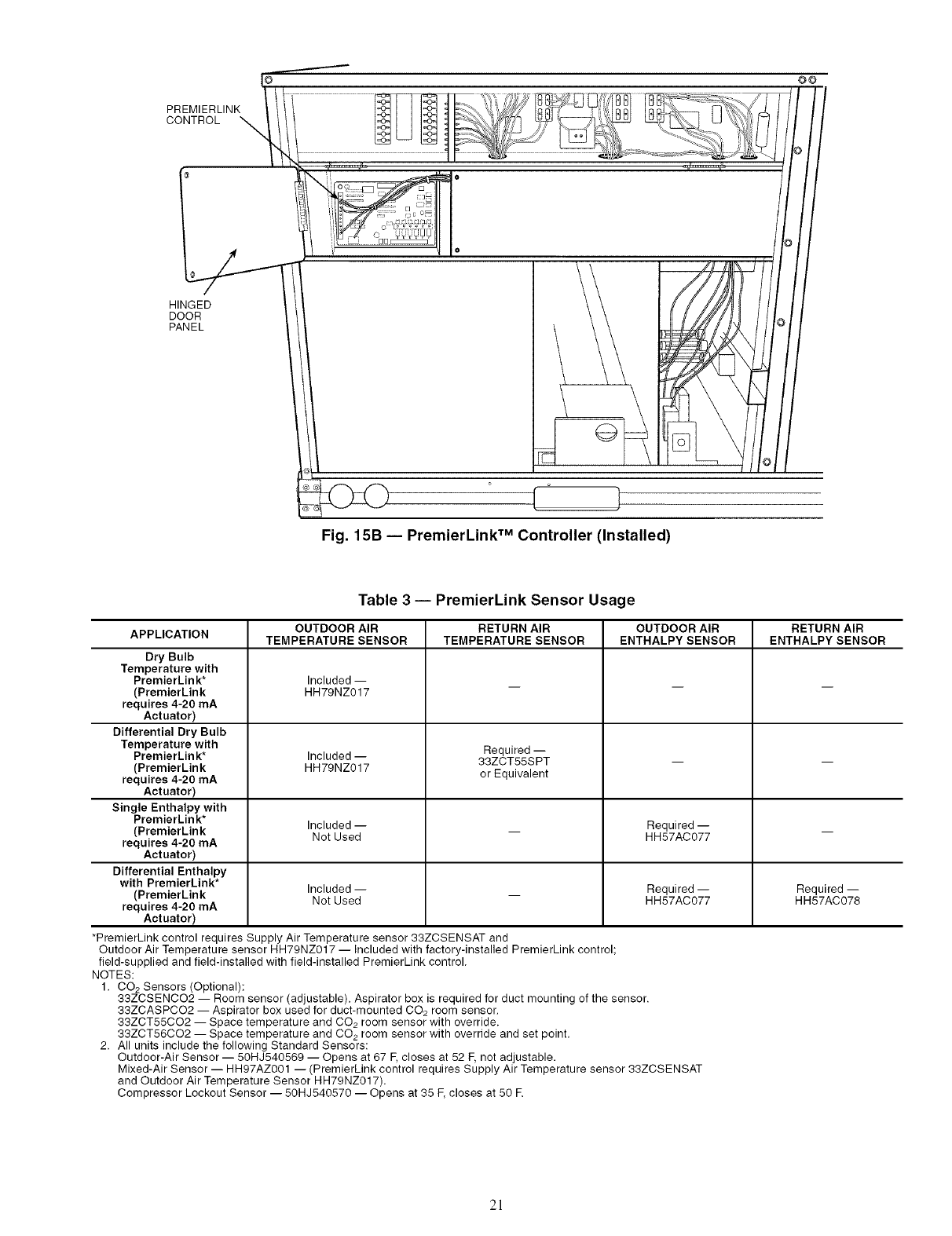
PREMIERLINK
CONTROL
OO
HINGED
DOOR
PANEL
o
,,j
/
/O l
Fig. 15B -- PremierLink TM Controller (Installed)
Table 3 -- PremierLink Sensor Usage
APPLICATION OUTDOOR AIR RETURN AIR OUTDOOR AIR RETURN AIR
TEMPERATURE SENSOR TEMPERATURE SENSOR ENTHALPY SENSOR ENTHALPY SENSOR
Dry Bulb
Temperature with
PremierLink* Included --
(PremierLink HH79NZ017
requires 4-20 mA
Actuator)
Differential Dry Bulb
Temperature with Required --
PremierLink* Included -- 33ZCT55SPT -- --
(PremierLink HH79NZ017 or Equivalent
requires 4-20 mA
Actuator)
Single Enthalpy with
PremierLin k*
(PremierLink Included -- _ Required -- _
Not Used HH57AC077
requires 4-20 mA
Actuator)
Differential Enthalpy
with PremierLink*
(PremierLink Included -- _ Required -- Required --
Not Used HH57AC077 HH57AC078
requires 4-20 mA
Actuator)
*PremierLink control requires Supply Air Temperature sensor 33ZCSENSAT and
Outdoor Air Temperature sensor HH79NZ017 -- Included with factory-installed PremierLink control;
field-supplied and field-installed with field-installed PremierLink control.
NOTES:
1. CO2 Sensors (Optional):
33ZCSENCO2 -- Room sensor (adjustable). Aspirator box is required for duct mounting of the sensor.
33ZCASPCO2 -- Aspirator box used for duct-mounted CO2 room sensor.
33ZCT55CO2 -- Space temperature and CO2 room sensor with override.
33ZCT56CO2 -- Space temperature and CO2 room sensor with override and set point.
2. All units include the following Standard Sensors:
Outdoor-Air Sensor -- 50HJ540569 -- Opens at 67 F,closes at 52 F,not adjustable.
Mixed-Air Sensor -- HH97AZ001 -- (PremierLink control requires Supply Air Temperature sensor 33ZCSENSAT
and Outdoor Air Temperature Sensor HH79NZ017).
Compressor Lockout Sensor -- 50HJ540570 -- Opens at 35 E closes at 50 R
2!
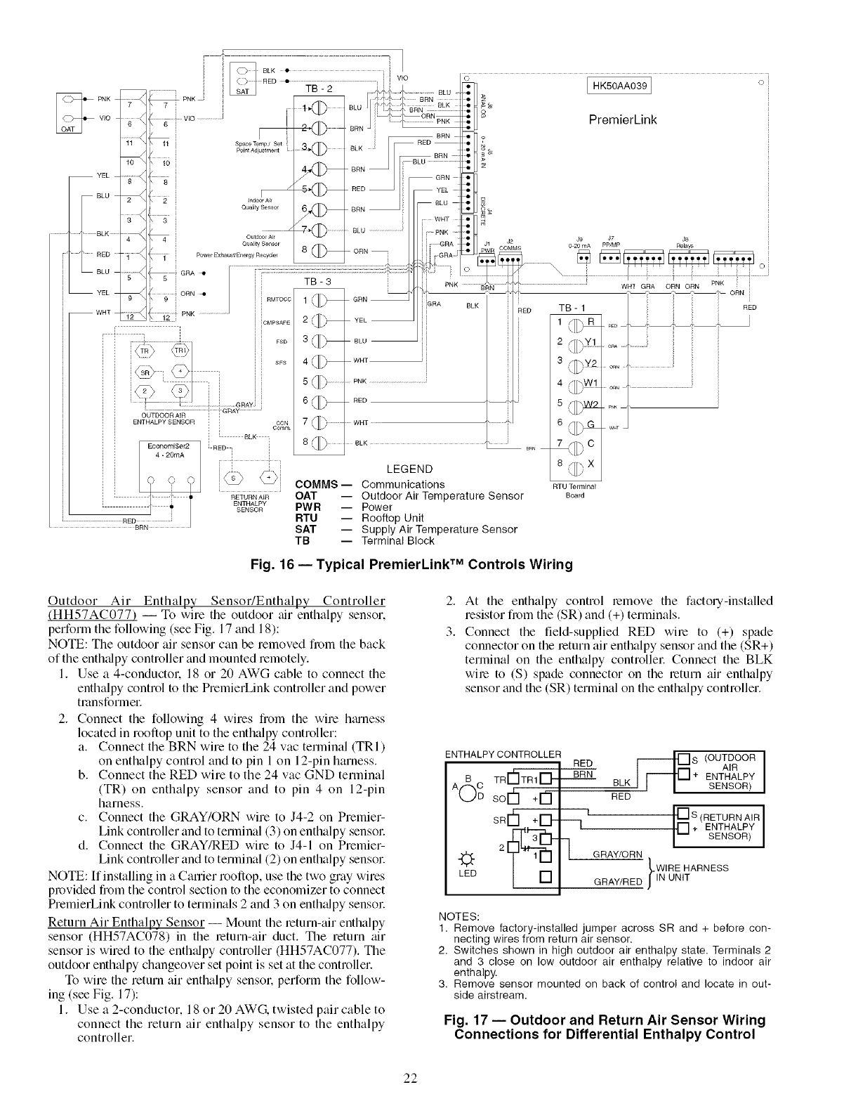
*PremierLink_. 3
rio _
............._/ 6 VIO _ @ BRN ] ......... ....
11 "- 11 SpaceTempJ Set RED •
4,,( _ BRN_ _z
YEL 8 _ /qT__X._J /RED _GRN _!1
2 \ 2 Indoor Ai
/_ ii .............. 6_ BRN _ _BLU _
Quality Sensor i i f GRA !ll Jl 0 20 mA PP'MP Re ays
f 8 ORN- i I _ PWR OOMMS
......................................................................?_ .............................,.........................................................................
11_,_,u-_ _[_H !_ PNK BRN "i" WH] GRA ORN ORN PNK [
YEL ORN 41 _ _ _ " _ _-" _ ORN
WHT ............'/ : PNK l XLW iGRA BLK RED TB-1 i nED
" :1 ] .... 3 /] _8LU _ i 2 _.vl l
[ 4TR) \TR1_I i _ 'LL/
:i [[J\ /7\/ SFS 4 [[1_ WHT i 3 {_Y2
_S:_ i _t i 5_[) ................ PNK .............................................. 4 []DW! ....
OUTDOOR AIR ! GRAY
ENTHALPYSENSOR i i CON 7 (][_, WHT 6 _[).JSL
Co,r_r wm
iLBLK
E....... lSer2 [RED, i 8 (1_ 8LK " 7 rl] % C
8#-_X
LEGEND ,._/
C 0 0 _ XC/ COMMS-- Communications RZUt_m_i_l
'RETURNAIROAT -- Outdoor Air TemperatureSensor Board
ENTHALPY
SENSOR PWR -- Power
RTU -- Rooftop Unit
SAT -- Supply Air Temperature Sensor
TB -- Terminal Block
Fig. 16 -- Typical PremierLink TM Controls Wiring
Outdoor Air Enthalpy SensoffEnthalpy Controller
(HH57AC077) -- To wire the outdoor tfir enthalpy sensor.
perform the following (see Fig. 17 and 18):
NOTE: The outdoor air sensor can be removed from the back
of the enth_dpy controller and mounted remotely.
1. Use a 4-conductor. 18 or 20 AWG cable to connect the
enthalpy control to the PremierLink controller and power
tmnsformec
2. Connect the following 4 wires from the wire htuness
located in rooftop unit to the enthalpy controller:
a. Connect the BRN wire to the 24 vac terminal (TRI)
on enthalpy control and to pin 1 on 12-pin harness.
b. Connect the RED wire to the 24 vac GND terminal
(TR) on enthalpy sensor and to pin 4 on 12-pin
harness.
c. Connect the GRAY/ORN wire to J4-2 on Premier-
Link controller and to terminal (3) on enthalpy sensoc
d. Connect the GRAY/RED wire to J4-1 on Premier-
Link controller and to terminal (2) on enthalpy sensoc
NOTE: If installing in a Carrier rooftop, use the two gray wires
provided from the control section to the economizer to connect
PremierLink controller to terminals 2 and 3 on enth_dpy sensoc
Return Air Enthalpy Sensor -- Mount the return-air enthalpy
sensor (HH57AC078) in the return-air duct. The return air
sensor is wired to the enth_dpy controller (HH57AC077). The
outdoor enthalpy changeover set point is set at the controller.
To wire the return air enthalpy sensor, perform the follow-
ing (see Fig. 17):
1. Use a 2-conductor, 18 or 20 AWG. twisted pair cable to
connect the return air enthalpy sensor to the enthalpy
controller.
2. At the enthalpy control remove the factory-installed
resistor from the (SR) and (+) terminals.
3. Connect the field-supplied RED wire to (+) spade
connector on the return air enthalpy sensor and the (SR+)
terminal on the enthalpy controllec Connect the BLK
wire to (S) spade connector on the return air enthalpy
sensor and the (SR) terminal on the enthalpy controller.
ENTHALPY CONTROLLER RED
A6 C TRrI'ITRII__ BRN
soi-h +13
SRI-h --i
LED
_S (OUTDOOR I
AIR
+ ENTHALPY
BLK SENSOR)
RED
I [] S (RETURN AIR [
rl + ENTHALPY
-- SENSOR
G RAY/O RN
LWIRE HARNESS
GRAY/RED JiN UNIT
NOTES:
1. Remove factory-installed jumper across SR and + before con-
necting wires from return air sensor.
2, Switches shown in high outdoor air enthalpy state. Terminals 2
and 3 close on low outdoor air enthalpy relative to indoor air
enthalpy.
3. Remove sensor mounted on back of control and locate in out-
side airstream.
Fig. 17 -- Outdoor and Return Air Sensor Wiring
Connections for Differential Enthalpy Control
22
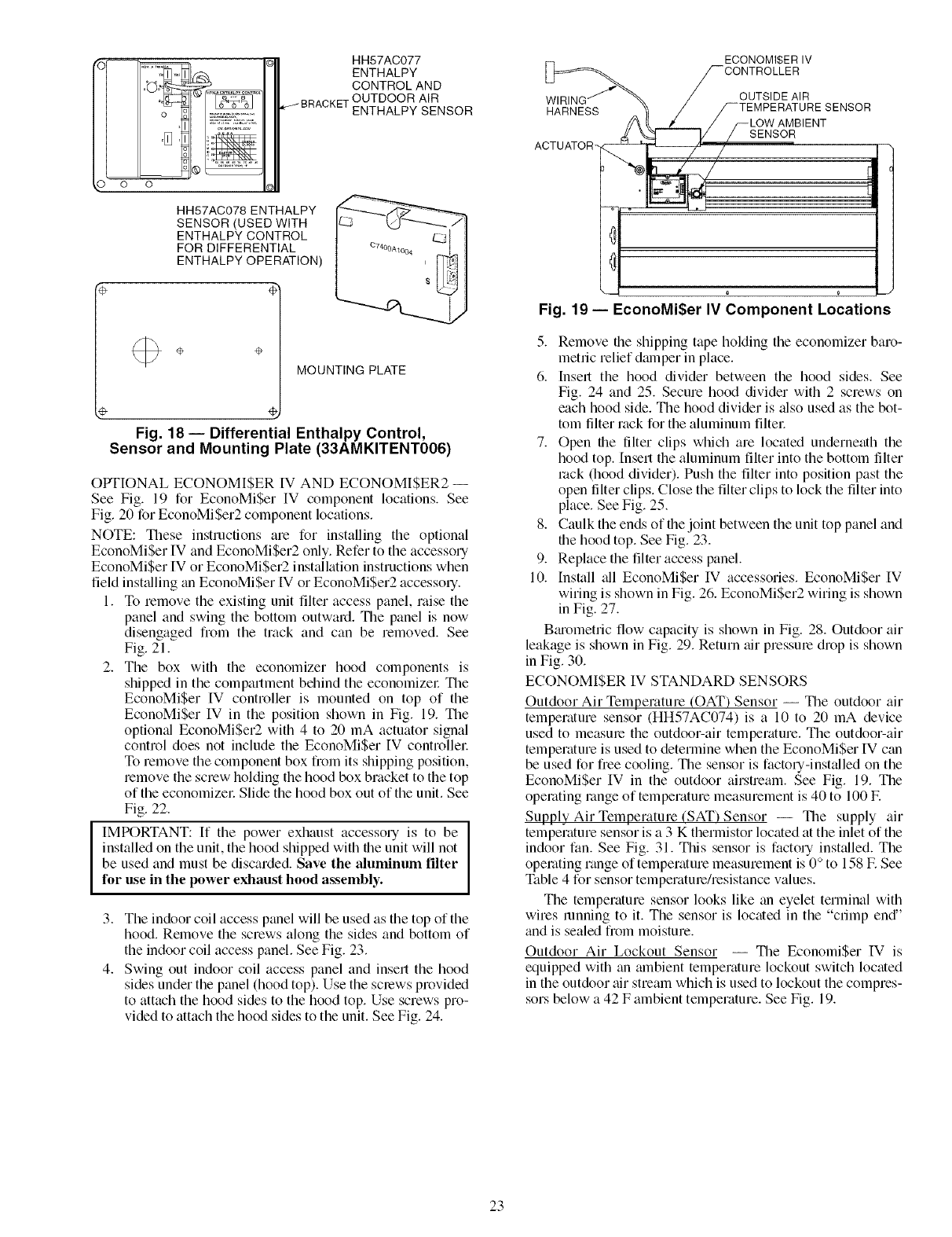
HH57AC077
ENTHALPY
CONTROL AND
•OUTDOOR AIR
ENTHALPY SENSOR
HH57AC078 ENTHALPY
SENSOR(USED WITH
ENTHALPY CONTROL
FOR DIFFERENTIAL
ENTHALPY OPERATION)
÷ ÷ MOUNTING PLATE
%
Fig. 18- Differential Enthalpy Control,
Sensor and Mounting Plate (33AMKITENT006)
OPTIONAL ECONOMI$ER [V AND ECONOMISER2 --
See Fig. 19 for EconoMi$er IV component locations. See
Fig. 20 for EconoMiSer2 component locations.
NOTE: These instructions are for installing the optional
EconoMiSer IV and EconoMiSer2 only. Refer to the accessory
EconoMi$er IV or EconoMiSer2 installation instructions when
field inst_flling an EconoMiSer IV or EconoMiSer2 accesso q.
1. To remove the existing unit filter access panel, raise the
panel and swing the bottom outward. The panel is now
disengaged from the track and can be removed. See
Fig. 21.
2. The box with the economizer hood components is
shipped in the compartment behind the economizel: Tile
EconoMi$er IV controller is mounted on top of the
EconoMiSer IV in the position shown in Fig. 19. The
optional EconoMi$er2 with 4 to 20 mA actuator signal
control does not include the EconoMi$er IV controllel:
To remove the component box from its shipping position,
remove the screw holding the hood box bracket to the top
of the economizel: Slide the hood box out of the unit. See
Fig. 22.
IMPORTANT: If the power exhaust accessory is to be
installed on the unit, the hood shipped with the unit will not
be used and must be discarded. Save the aluminum filter
for use in the power exhaust hood assembly.
3. The indoor coil access panel will be used as the top of the
hood. Remove the screws along the sides and bottom of
the indoor coil access panel. See Fig. 23.
4. Swing out indoor coil access panel and insert the hood
sides under the panel (hood top). Use the screws provided
to attach the hood sides to the hood top. Use screws pro-
vided to attach the hood sides to the unit. See Fig. 24.
HARNESS
ACTUATOR-
ECONOMI$ER IV
-CONTROLLER
OUTSIDE AIR
¢TEMPERATURE SENSOR
LOW AMBIENT
SENSOR
/I '
Fig. 19- EconoMi$er IV Component Locations
5. Remove file shipping tape holding the economizer baro-
metric relief damper in place.
6. Insert the hood divider between the hood sides. See
Fig. 24 and 25. Secure hood divider with 2 screws on
each hood side. The hood divider is also used as the bot-
tom filter rack for the aluminum filtel:
7. Open file filter clips which are located underneath the
hood top. Insert the aluminum filter into the bottom filter
rock (hood divider). Push the filter into position past the
open filter clips. Close the filter clips to lock the filter into
place. See Fig. 25.
8. Caulk the ends of the joint between the unit top panel and
the hood top. See Fig. 23.
9. Replace the filter access panel.
10. [nsmll all EconoMiSer IV accessories. EconoMi$er IV
wiring is shown in Fig. 26. EconoMiSer2 wiring is shown
in Fig. 27.
Bmometric flow capacity is shown in Fig. 28. Outdoor air
leakage is shown in Fig. 29. Return air pressure drop is shown
in Fig. 30.
ECONOMISER IV STANDARD SENSORS
Outdoor Air Temperature (OAT) Sensor -- The outdoor air
temperature sensor (HH57AC074) is a 10 to 20 mA device
used to measme the outdoor-air temperature. The outdoor-air
temperature is used to determine when the EconoMiSer IV can
be used for free cooling. The sensor is factory-installed on the
EconoMiSer IV in the outdoor airstream. See Fig. 19. The
operating range of temperature measurement is 40 to 100 E
Supply Air Temperature (SAT) Sensor -- The supply air
temperature sensor is a 3 K thermistor located at the inlet of the
indoor fan. See Fig. 31. This sensor is factory installed. The
operating range of temperature measurement is 0 ° to 158 E See
Table 4 for sensor temperatme/resistance values.
The temperature sensor looks like an eyelet terminal with
wires running to it. The sensor is located in the "crimp end"
and is sealed from moisture.
Outdoor Air Lockout Sensor -- The EconomiSer IV is
equipped with an mnbient temperature lockout switch located
in the outdoor air stream which is used to lockout the compres-
sors below a 42 F ambient temperature. See Fig. 19.
23
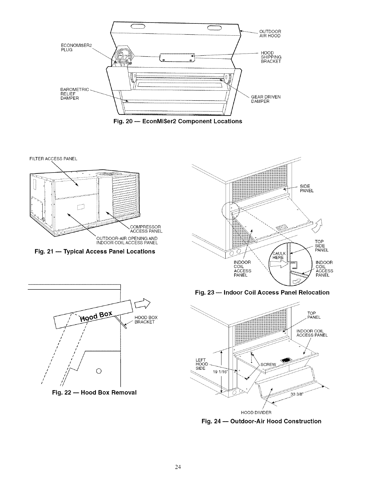
ECONOMI$ER2
PLUG
BAROMETRIC
RELIEF
DAMPER
C22_
teB
Fig. 20 -- EconMi$er2 Component Locations
-_ UTDOOR
AIR HOOD
HOOD
SHIPPING
BRACKET
_'_ GEAR DRIVEN
DAMPER
FILTER ACCESS PANEL
COMPRESSOR
ACCESS PANEL
OUTDOOR-AIR OPENING AND
INDOOR COILACCESS PANEL
Fig. 21 -- Typical Access Panel Locations
i/
I
it I
I
/
I I
I
11 0
I
!
!
Fig. 22 -- Hood Box Removal
HOOD BOX
BRACKET
SIDE
PANEL
INDOOR
COIL
ACCESS
PANEL
TOP
SIDE
PANEL
INDOOR
COIL
ACCESS
PANEL
Fig. 23 -- Indoor Coil Access Panel Relocation
TOP
INDOORCOIL
ACCESS PANEL
LEFT
SIDE
33 3/8"
HOOD DIVIDER
Fig. 24 -- Outdoor-Air Hood Construction
24
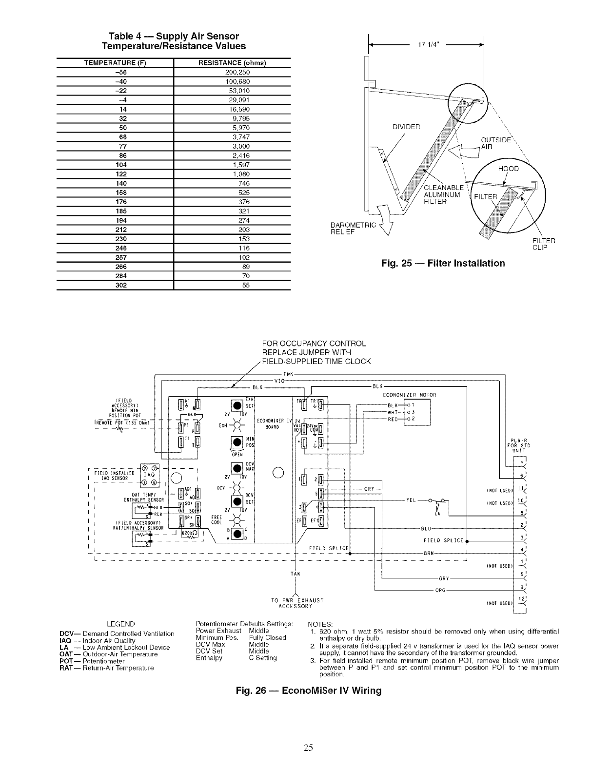
Table 4 -- Supply Air Sensor /
Temperature/Resistance Values _ 17 1/4" --
TEMPERATURE (F) RESISTANCE (ohms)
-58 200,250
-40 100,680
-22 53,010
-4 29,091
14 16,590
32 9,795
50 5,970
68 3,747
77 3,000
86 2,416
104 1,597
122 1,080
140 746
158 525
176 376
185 321
194 274
212 203
230 153
248 116
257 102
266 89
284 70
302 55
HOOD
ALUMINUM
FILTER
BAROMETRIC ,
RELIEF
Fig. 25 -- Filter Installation
FILTER
CLIP
FOR OCCUPANCY CONTROL
REPLACE JUMPER WITH
j-FIELD-SUPPLIED TIME CLOCK
// P.K
VlO-
#( BLK BLK
)EIELD N1 T_
ACCESSORY) _ BLK
RENOIENIN
POSITIONPOT BLK _V IOV WHT
'R_O_POT_I_O_m)- _-_i_ _ ECONOMIIERIV RED
_ _ ___ __ EXN BOARS !,_Oc_%i
pos
OPEN
r-- _HAX
FIELD _S_LL_D ]O
I IAO SENSOR ]Ev lOV
," 0AFFE.P, ,'
IIERTRALPY SENSOR
BLK-- 2V IOV
IIRRD-i SR* FREE
I I )FIELDACCZSSORY)__L _[]
RAFIENFNALPYSENSOR BC-- BLU
1 1 A O FIELD SPLICE
]IFIELD SPLICE
BRN
L
TAN
6RY
ORG
TO PWR EXHAUST
ACCESSORY
(NOr USED)
{NOT USED}
)NOr USED)
(Nor USED)
PL6-R
% 77°
<
<
<
<
LEGEND
DCV-- Demand Controlled Ventilation
IAQ -- Indoor Air Quality
LA -- Low Ambient Lockout Device
OAT-- Outdoor-Air Temperature
POT-- Potentiometer
RAT-- Return-Air Temperature
Potentiometer Defaults Settings:
Power Exhaust Middle
Minimum Pos. Fully Closed
DCV Max. Middle
DCV Set Middle
Enthalpy C Setting
NOTES:
1, 620 ohm, 1 watt 5% resistor should be removed only when using differential
enthalpy or dry bulb.
2. If a separate field-supplied 24 v transformer is used for the IAQ sensor power
supply, it cannot have the secondary of the transformer grounded.
3, For field-installed remote minimum position POT, remove black wire jumper
between P and P1 and set control minimum position POT to the minimum
position,
Fig. 26 -- EconoMi$er IV Wiring
25
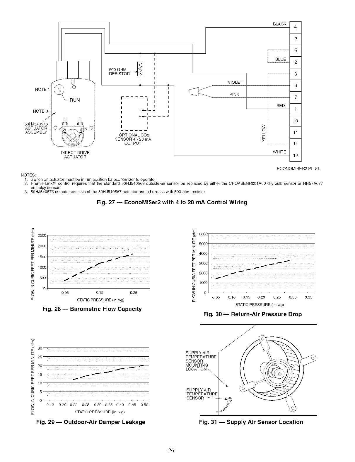
NOTE1
NOTE 3
J
50HJ540573
ACTUATOR
ASSEMBLY
DIRECT DRIVE
ACTUATOR
?
500 OHM _J<>l
RESISTOR- "_ T
I
i- I I
I
II
. ___1_ I
I
+_-I .... J
I
I
OPTIONAL CO2
SENSOR 4 - 20 rnA
OUTPUT
BLACK
VIOLET
PINK
RED
S
u
ku
>-
WHITE
4
3
5
2
8
6
7
1
10
11
9
12
ECONOMIZER2 PLUG
NOTES:
1. Switch on actuator must be in run position for econornizer to operate.
2. PremierLink TM control requires that the standard 50HJ540569 outside-air sensor be replaced by either the CROASENR001A00 dry bulb sensor or HH57A077
enthalpy sensor.
3. 50HJ540573 actuator consists of the 50HJ540567 actuator and a harness with 500-ohm resistor.
Fig. 27 -- EconoMi$er2 with 4 to 20 mA Control Wiring
_o 2500
W
2000
w 1500
w
w 1000
L
500
©
z
S
L
iii i i i i ii _,_ _iiiiiiiiiiiiiiiiiiiiiiiiiiiiiiiiiiiii
s'
I
0.'05 0115 0.'25
STATIC PRESSURE (in. wg)
Fig. 28 -- Barometric Flow Capacity
eooo
w
D 5000
4000
w
3000
w
w
L
© 2000
1000
z
o
S
L0.05 0.10 0.15 0.20 0.25 0.30 0.35
STATIC PRESSURE (in. wg)
Fig. 30- Return-Air Pressure Drop
/
LU 30
I--
z_ 25
13:: 20
D_
_ 15
W
kU
U. 10
o5
o
z 0
0.13 0.20 0.22 0.25 0.30 0.35 0.40 0.45 0.50
t_
_I STATIC PRESSURE (in. wg)
LL
Fig. 29 -- Outdoor-Air Damper Leakage
SUPPLY AIR
TEMPERATURE
SENSOR
MOUNTING
LOCATION
\
SUPPLY AIR
TEMPERATURE
SENSOR s
Fig. 31 -- Supply Air Sensor Location
26
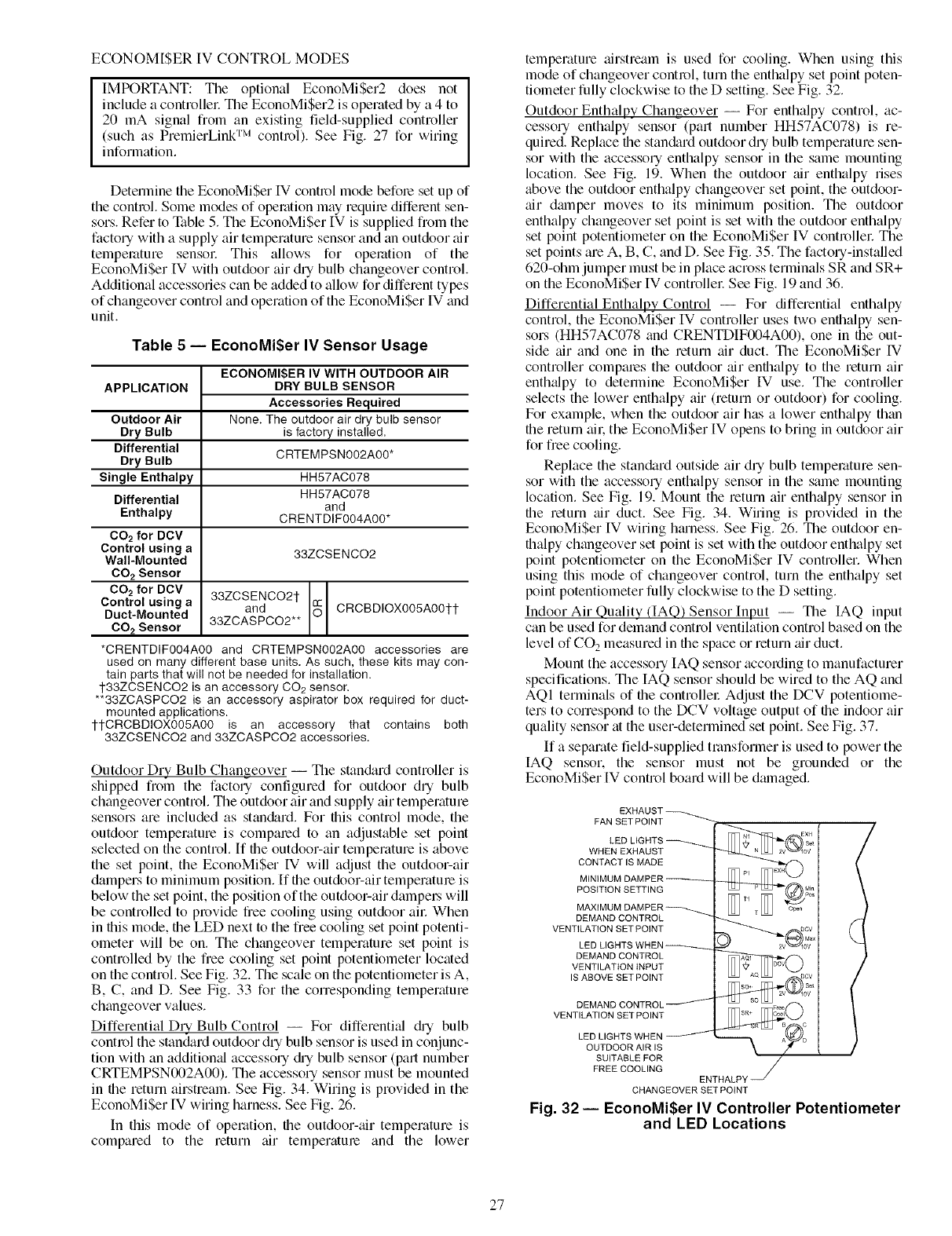
ECONOMI$ER IV CONTROL MODES
IMPORTANT: Tile optional EconoMiSer2 does not
include a controllel: The EconoMiSer2 is operated by a 4 to
20 mA signal from an existing field-supplied controller
(such as PremierLink TM control). See Fig. 27 for wiring
information.
Determine tile EconoMiSer IV control mode befole set up of
the control. Some modes of operation may requile diffelent sen-
sors. Refer to Ntble 5. The EconoMiSer IV is supplied from the
factory with a supply air temperature sensor and an outdoor air
temperature sensol: This allows for operation of the
EconoMiSer IV with outdoor air dry bulb changeover control.
Additional accessories c_m be added to allow for different types
of changeover control and operation of the EconoMiSer IV and
unit.
Table 5 -- EconoMi$er IV Sensor Usage
APPLICATION
Outdoor Air
Dry Bulb
Differential
Dry Bulb
Single Enthalpy
Differential
Enthalpy
CO2 for DCV
Control using a
Wall-Mounted
CO2 Sensor
CO 2for DCV
Control using a
Duct-Mounted
CO2 Sensor
ECONOMI$ER IV WITH OUTDOOR AIR
DRY BULB SENSOR
Accessories Required
None. The outdoor air dry bulb sensor
is factory installed.
CRTEMPSN002A00*
HH57AC078
HH57AC078
and
CRENTDIF004A00*
33ZCSENCO2
33ZCSENCO21-
and CRCBDIOX005A001-1-
33ZCASPCO2**
*CRENTDIF004A00 and CRTEMPSN002A00 accessories are
used on many different base units. As such, these kits may con-
tain parts that will not be needed for installation.
1-33ZCSENCO2 is an accessory CO2 sensor.
**33ZCASPCO2 is an accessory aspirator box required for duct-
mounted applications.
1-1-CRCBDIOX005A00 is an accessory that contains both
33ZCSENCO2 and 33ZCASPCO2 accessories.
Outdoor Dry Bulb Changeover -- The stan&_rd controller is
shipped from the factory configured for outdoor dry bulb
changeover control. The outdoor air and supply air temperature
sensors are included as stan&_rd. For this control mode, the
outdoor temperature is compmed to an adjustable set point
selected on the control. If the outdoor-air temperature is above
the set point, the EconoMi$er IV will adjust the outdoor-air
dampers to minimum position. If the outdoor-air temperature is
below the set point, the position of the outdoor-air dampel.s will
be controlled to provide free cooling using outdoor all: When
in this mode, the LED next to the free cooling set point potenti-
ometer will be on. The changeover temperature set point is
controlled by the free cooling set point potentiometer located
on the control. See Fig. 32. The scale on the potentiometer is A,
B, C, and D. See Fig. 33 for the conesponding temperature
changeover values.
Differential Dry Bulb Control -- For differenti_d @ bulb
control the stan_lard outdoor dry bulb sensor is used in conjunc-
tion with an additiomd accessory @ bulb sensor (part number
CRTEMPSN002A00). The accessory sensor must be mounted
in the return airstream. See Fig. 34. Wiring is provided in the
EconoMiSer IV wiring harness. See Fig. 26.
In this mode of operation, the outdoor-air temperature is
compared to the return air temperature and the lower
temperature airstream is used for cooling. When using this
mode of changeover control, turn the enthalpy set point poten-
tiometer fully clockwise to the D setting. See Fig. 32.
Outdoor Enthalpy Changeover -- For enthalpy control, ac-
cessory enthalpy sensor (part number HH57AC078) is re-
quired. Replace the stan&_rd outdoor dry bulb temperature sen-
sor with the accessory enthalpy sensor in the same mounting
location. See Fig. 19. When the outdoor air enthalpy rises
above the outdoor enthalpy changeover set point, the outdoor-
tdr dmnper moves to its minimum position. The outdoor
enthalpy changeover set point is set with the outdoor enthalpy
set point potentiometer on the EconoMiSer IV controllec The
set points are A, B, C, and D. See Fig. 35. The factory-installed
620-ohm jumper must be in place across terminals SR and SR+
on the EconoMiSer IV controllel: See Fig. 19 and 36.
Differential Enthalpy Control -- For differential enthalpy
control, the EconoMiSer IV controller uses two enthalpy sen-
sors (HH57AC078 and CRENTDIF004A00), one in the out-
side air and one in the return air duct. The EconoMiSer IV
controller compares the outdoor air enthalpy to the return air
enth_dpy to determine EconoMiSer IV use. The controller
selects the lower enthalpy air (return or outdoor) for cooling.
For example, when the outdoor air has a lower enth_dpy than
the return ail, the EconoMiSer IV opens to bring in outdoor air
for free cooling.
Replace the standard outside air dry bulb temperature sen-
sor with the accessory enthalpy sensor in the same mounting
location. See Fig. 19. Mount the return air enth_dpy sensor in
the return _dr duct. See Fig. 34. Wiring is provided in the
EconoMi$er IV wiring hmness. See Fig. 26. The outdoor en-
thalpy changeover set point is set with the outdoor enthalpy set
point potentiometer on the EconoMiSer IV controller. When
using this mode of changeover control, turn the enthalpy set
point potentiometer fully clockwise to the D setting.
Indoor Air Quality (IAQ) Sensor Input -- The IAQ input
can be used for demand control ventilation control based on the
level of CO 2 measured in the space or return air duct.
Mount the accessory IAQ sensor according to manufacturer
specifications. The IAQ sensor should be wired to the AQ and
AQI terminals of the controller Adjust the DCV potentiome-
ters to correspond to the DCV voltage output of the indoor air
quality sensor at the user-determined set point. See Fig. 37.
If a separate field-supplied transformer is used to power the
[AQ sensor, the sensor must not be grounded or the
EconoMiSer IV control board will be dmnaged.
FAN SET POINT
WHEN EXHAUST
CONTACT IS MADE
POSITION SETTING
DEMAND CONTROL
VENTILATION SET POINT
DEMAND CONTROL
VENTILATION iNPUT
IS ABOVE SET POINT
VENTILATION SET POINT
LED LIGHTS WHEN
OUTDOOR AIR IS
SUITABLE FOR
FREE COOLING ENTHALP_
CHANGEOVER SET POINT
Fig. 32 -- EconoMi$er IV Controller Potentiometer
and LED Locations
27
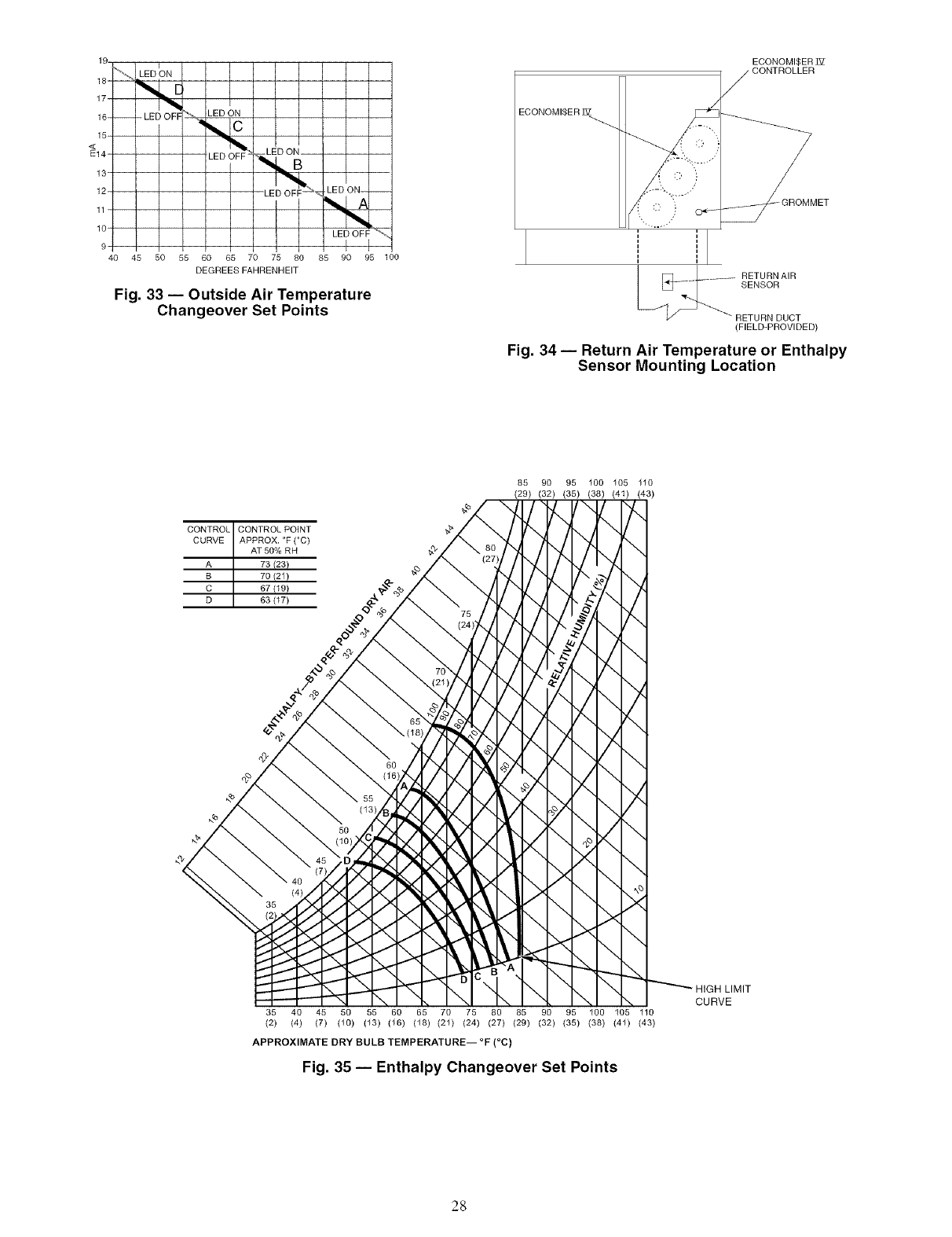
19.
18- _'_
17-
16---
15-
<
E14-
13"
12-
11-
10"
LED _ON
LED OFF LED ON
LED OFF-
40 45 50 55 60 65 70 75 80
DEGREES FAHRENHEIT
I
-LED OFF_"_ LED ON- --
I
85 90 95 100
Fig. 33 -- Outside Air Temperature
Changeover Set Points
ECONOMI$ER ]_Z
ECONOMI$ER ]_
X CONTROLLER
-RETURNAIR
SENSOR
RETURN DUCT
(FIELD-PROVIDED)
Fig. 34 -- Return Air Temperature or Enthalpy
Sensor Mounting Location
CONTROL CONTROL POINT
CURVE APPROX. °F (°C)
AT 50% RH
A 73 (23}
B 70 (21)
C 67 (19}
D 63 (17)
85 90 95 100 105 110
(29) (32) (35) (38) (4I) (43)
"1,,,
,,./
7-,
\
-,./
/..
\
5(
\
\
X
\
HIGH LIMIT
\ CURVE
35 40 45 50 55 60 65 70 75 80 85 90 95 100 105 110
(2) (4) (7) (10) (13) (16) (18) (21) (24) (27) (29) (32) (35) (38) (41) (43)
APPROXIMATE DRY BULB TEMPERATURE-- °F (°C)
Fig. 35 -- Enthalpy Changeover Set Points
28

MEx©
PU _Mi0
Pos
T _I_]I Open
V_l DCV
Ma/
2 0V
I bll_ II T_
24 24 Vac
Vac OOM
HO_T_
m
2
5
4
FFr_I EF1
Fig. 36 -- EconoMiSer IV Control
CO2 SENSOR MAX RANGE SETTING
6000
+800 pprn
__ +9OOppm
1000 ppm
+1100 ppm
0
23 45678
DAMPER VOLTAGE FOR MAX VENTILATION RATE
Fig. 37 -- CO 2 Sensor Maximum Range Setting
5000
z4000
3000
E
Z
8 2000
W
z 1000
<
Exhaust Set Point Adjustment -- The exhaust set point will
determine when the exhaust fan runs based on &_mper position
(if accessory power exhaust is installed). The set point is modi-
fied with the Exhaust Fan Set Point (EXH SET) potentiometer
See Fig. 32. The set point represents the damper position above
which the exhaust fans will be turned on. When there is a call
for exhaust, the EconoMiSer IV controller provides a 45 _+15
second delay before exhaust fan activation to allow the damp-
ers to open. This delay allows the &tmper to reach the appro-
priate position to avoid unnecessary fan overload.
Minimum Position Control -- There is a minimum &tmper
position potentiometer on the EconoMiSer IV controllel: See
Fig. 32. The minimum dmnper position maintains the mini-
mum airflow into the building during the occupied period.
When using demand ventilation, the minimum damper po-
sition represents the minimum ventilation position for VOC
(volatile organic compound) ventilation requirements. The
maximum demand ventilation position is used for fully occu-
pied ventilation.
When demand ventilation control is not being used, the
minimum position potentiometer should be used to set the oc-
cupied ventilation position. The maximum demand ventilation
position should be turned fully clockwise.
Adjust the minimum position potentiometer to _llow the
minimum amount of outdoor air. as requiled by local codes, to
enter the building. Make minimum position adjustments with
at least 10 F temperature difference between the outdoor and
leturn-air temperatures.
To determine the minimum position setting, perform the
following procedure:
1. Calculate the appropriate mixed air temperature using the
following formula:
OA RA
(To x 1---_ ) + (TR x 1---_-_-) = T M
To = Outdoor-Air Temperature
OA = Percent of Outdoor Air
T R= Return-Air Telnperature
RA = Percent of Return Air
T M= Mixed-Air Temperature
As an example, if local codes require 10% outdoor air
during occupied conditions, outdoor-air temperature is
60 IF.and return-air temperature is 75 E
(60 x. 10) + (75 x .90) = 73.5 F
2. Disconnect the supply air sensor from terminals T and
TI.
3. Ensure that the factory-installed jumper is in place across
terminals P and PI. [f remote dmnper positioning is being
used, make sure that the terminals are wired according to
Fig. 26 and that the minimum position potentiometer is
turned fully clockwise.
4. Connect 24 vac across terminals TR and TRI.
5. Carefully adjust the minimum position potentiometer
until the measured mixed-air temperature matches the
calculated value.
6. Reconnect the supply air sensor to terminals T and TI.
Remote control of the EconoMiSer IV dmnper is desirable
when requiring additional temporary ventilation. If a
field-supplied remote potentiometer (Honeywell Dut number
$963B1128) is wired to the EconoMiSer IV controller, the
minimum position of the damper can be controlled fi_m a re-
mote location.
To control the minimum damper position remotely, remove
the factory-installed jumper on the P and PI terminals on the
EconoMiSer IV controllel: Wire the field-supplied potentiome-
ter to the P and PI terminals on the EconoMiSer IV controllel:
See Fig. 36.
Damper Movement -- Damper movement from full open to
lull closed (or vice versa) takes 21/2 minutes.
Thermostats -- The EconoMiSer IV control works with con-
ventional thermostats that have a YI (cool stage 1), Y2 (cool
stage 2), WI (heat stage 1), W2 (heat stage 2), and G (fan). The
EconoMi$er [V control does not support space temperature
sensors. Connections me made at the themlostat terminal con-
nection board located in the main control box.
Occupancy Control -- The factory default configuration for
the EconoMiSer IV control is occupied mode. Occupied status
is provided by the black jumper from terminal TR to terminal
N. When unoccupied mode is desired, install a field-supplied
timeclock lunction in place of the jumper between TR and N.
See Fig. 26. When the timeclock contacts are closed, the
EconoMiSer IV control will be in occupied mode. When the
timeclock contacts are open (removing the 24-v signal from
terminal N), the EconoMiSer IV will be in unoccupied mode.
Demand Controlled Ventilation (DCV) -- When using the
EconoMi$er IV for demand controlled ventilation, there me
some equipment selection criteria which should be considered.
When selecting the heat capacity and cool capacity of the
equipment, the maximum ventilation rate must be evaluated for
design conditions. The maximum damper position must be cal-
culated to provide the desired fresh ail:
29
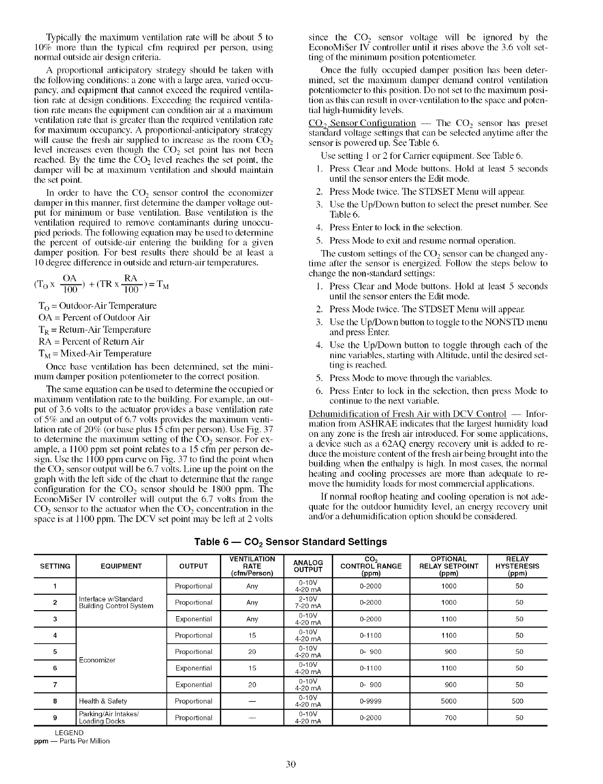
Typically tile maximum ventilation rate will be about 5 to
10_ ,more than the typical cfm required per pe_on, using
normal outside air design criteria.
A proportional anticipatory strategy should be taken with
the following conditions: a zone with a large area, varied occu-
pancy, and equipment that cannot exceed the required ventila-
tion rate at design conditions. Exceeding the required ventila-
tion rate means the equipment can condition air at a maximum
ventilation rate that is greater than the lequired ventilation rate
for maximum occupancy. A proportional-anticipatory strategy
will cause tile fresh air supplied to increase as the room CO2
level increases even though the CO 2 set point has not been
reached. By the time the CO 2 level reaches the set point, the
damper will be at maximum ventilation and should maintain
the set point.
In order to have the CO2 sensor control the economizer
damper in this manner, first detemfine file damper voltage out-
put for minimum or base ventilation. Base ventilation is the
ventilation required to remove contaminants during unoccu-
pied periods. The following equation may be used to determine
the percent of outside-air entering the building for a given
damper position. For best results thele should be at least a
10 degree difference in outside and leturn-air temperatures.
OA RA
(Tox 1-]"_) +(TRx I'T_)=TM
To = Outdoor-Air Temperature
OA = Percent of Outdoor Air
TR = Return-Air Temperature
RA = Percent of Return Air
T M= Mixed-Air Temperature
Once base ventilation has been detemfined, set the mini-
mum dmnper position potentiometer to the correct position.
The same equation can be used to determine the occupied or
maximum ventilation rate to the building. For example, an out-
put of 3.6 volts to the actuator provides a base ventilation rate
of 5% and an output of 6.7 volts provides the maximum venti-
httion rate of 20% (or base plus 15 cfln per person). Use Fig. 37
to determine the maximum setting of the CO 2 sensor For ex-
ample, a 1100 ppm set point relates to a 15 cfln per person de-
sign. Use the 1100 ppm curve on Fig. 37 to find the point when
the CO 2 sensor output will be 6.7 volts. Line up the point on the
graph with the left side of the chart to determine that the range
configuration for the CO 2 sensor should be 1800 ppm. The
EconoMiSer IV controller will output the 6.7 volts from the
CO 2 sensor to the actuator when the CO 2 concentration in the
space is at 1100 ppm. The DCV set point may be left at 2 volts
since the CO 2 sensor voltage will be ignored by the
EconoMiSer IV controller until it rises above the 3.6 volt set-
ting of the minimum position potentiometel:
Once the fully occupied dmnper position has been deter-
mined, set ti3e maximum dalnper demand control ventilation
potentiometer to this position. Do not set to the maximum posi-
tion as this can result in over-ventilation to the space and poten-
tial high-humidity levels.
CO, Sensor Configuration -- The CO 2sensor has preset
standard voltage settings timt can be selected anytime after the
sensor is powered up. See Table 6.
Use setting 1 or 2 for Carrier equipment. See Table 6.
1. Press Clear and Mode buttons. Hold at least 5 seconds
until the sensor enters the Edit mode.
2. Press Mode twice. The STDSET Menu will appear
3. Use tile Up/Down button to select the preset numbel: See
Table 6.
4. Press Enter to lock in file selection.
5. Press Mode to exit and resume normal operation.
The custom settings of the CO 2sensor can be changed any-
time after the sensor is energized. Follow the steps below to
change file non-stan&trd settings:
1. Press Clear and Mode buttons. Hold at least 5 seconds
until the sensor enters the Edit mode.
2. Press Mode twice. The STDSET Menu will appem:
3. Use the Up/Down button to toggle to the NONSTD menu
and press Entel:
4. Use the Up/Down button to toggle through each of the
nine variables, starting with Altitude, until file desired set-
ting is reached.
5. Press Mode to move through the variables.
6. Press Enter to lock in the selection, then press Mode to
continue to the next vmiable.
Dehumidification of Fresh Air with DCV Control -- Infor-
mation from ASHRAE indicates that the largest humidity load
on any zone is the fresh air introduced. For some applications,
a device such as a 62AQ energy recovely unit is added to re-
duce the moisture content of the fresh air being brought into the
building when file enthalpy is high. In most cases, the normal
heating and cooling processes am morn than adequate to m-
move the humidity loads for most commemial applications.
If normal rooftop heating and cooling operation is not ade-
quate for the outdoor humidity level, an energy recovery unit
and/or a dehumidification option should be considered.
Table 6 -- CO2 Sensor Standard Settings
SETTING
1
2
3
4
EQUIPMENT
Interface w/Standard
Building Control System
5
Economizer
6
7
8 Health & Safety
9 Parking/Air Intakes/
Loading Docks
LEGEND
ppm -- Parts Per Million
OUTPUT
Proportional
Proportional
Exponential
Proportional
Proportional
Exponential
Exponential
Proportional
Proportional
VENTILATION
RATE
(elm/Person)
Any
Any
Any
15
20
15
2O
ANALOG
OUTPUT
0-10V
4-20 mA
2-10V
7-20 mA
0-10V
4-20 mA
0-10V
4-20 mA
0-10V
4-20 mA
0-10V
4-20 mA
0-10V
4-20 mA
0-10V
4-20 mA
0-10V
4-20 mA
CO2
CONTROL RANGE
(ppm)
0-2000
0-2000
0-2000
0-1100
0- 900
0-1100
0- 900
0-9999
0-2000
OPTIONAL
RELAY SETPOINT
(ppm)
1000
1000
1100
1100
900
1100
900
5000
700
RELAY
HYSTERESIS
(pprn)
5O
5O
5O
5O
5O
5O
5O
5OO
5O
3O
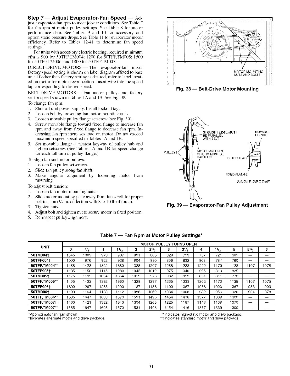
Step 7 -- Adjust Evaporator-Fan Speed -- Ad-
just evaporator-fan rpnl to meet jobsite conditions. See Table 7
for fan rpm at motor pulley settings. See Table 8 for motor
performance data. See Tables 9 and 10 for accessory trod
option static pressure drops. See Table 11 for evaporator motor
efficiency. Refer to Tables 12-41 to determine fan speed
settings.
For units with accessory electric heating, required minimum
cfm is 900 for 50TFKTM004; 1200 for 50TFF.TM005; 1500
for 50TFETM006; and 1800 for 50TFETM007.
DIRECT-DRIVE MOTORS -- The evaporator-fan motor
factory speed setting is shown on label diagram affixed to base
unit. If other than factory setting is desired, refer to label locat-
ed on motor for motor reconnection. Insert wire into the speed
tap corresponding to desired speed.
BELT-DRIVE MOTORS- Fan motor pulleys are factory
set for speed shown in Tables IA and lB. See Fig. 38.
To change fan rpm:
1. Shut off unit power supply. Install lockout tag.
2. Loosen belt by loosening fan motor mounting nuts.
3. Loosen movable pulley fange setscrew (see Fig. 39).
4. Screw movable flange tow;ud fixed flange to inclease fan
rpm and away from fixed flange to decrease fan rpm. In-
creasing fan rpm increases load on motor. Do not exceed
maximum speed specified in Tables IA and lB.
5. Set movable flange at nearest keyway of pulley hub and
tighten setscrew. (See Tables I A and IB for speed change
for each lidl turn of pulley flange.)
To align fan and motor pulleys:
1. Loosen fan pulley setscrews.
2. Slide fan pulley along fan shaft.
3. Make angulgu" alignment by
mounting.
To adjust belt tension:
1. Loosen fan motor mounting nuts.
2.
loosening motor from
Slide motor mounting plate away from fan scroll for proper
belt tension (1/2-in. deflection with 8 to 10 lb of force).
3. Tighten nuts.
4. Adjust bolt and tighten nut to secure motor in fixed position.
5. Re-inspect pulley alignment.
ioi
iJ
MOTOR MOUNTING
NUTS AND BOLTS
Fig. 38 -- Belt-Drive Motor Mounting
PULLEYS_
Fig. 39 -- Eva
ISTRAIGHT EDGE MUST MOVABLE
BE PARALLEL FLANGE
WITH BELT [_
MO!OR AND FAN
SHAFTS MUST BE )_.,,i_) l
:3_ ARALLEL SETSCREWS_F _
FIXED FLANGE
I SINGLE-GROOVE
mrator-Fan Pulley Adjustment
Table 7 -- Fan Rpm at Motor Pulley Settings*
MOTOR PULLEY TURNS OPEN
UNIT 0 1_ 1 11& 2 21& 3 31& 4 41_ 5 51& 6
50TM004t 1045 1009 973 937 901 865 829 793 757 721 685 -- --
50TFF004t 1000 976 952 928 904 880 856 832 808 784 760 -- --
50TF_TM004** 1455 1423 1392 1360 1328 1297 1265 1233 1202 1170 1138 1107 1075
50TFF005t 1185 1150 1115 1080 1045 1010 975 940 905 810 835 -- --
50TM005t 1175 1135 1094 1054 1013 973 932 892 851 811 770 -- --
50TF_TM005** 1455 1423 1392 1360 1326 1297 1265 1233 1202 1170 1138 1107 1075
50TFF006t 1300 1267 1233 1200 1167 1133 1100 1067 1033 1000 967 933 900
50TM006t 1190 1164 1138 1112 1086 1060 1034 1008 982 956 930 904 878
50TF_TM006** 1685 1647 1608 1570 1531 1493 1454 1416 1377 1339 1300 -- --
50TF_TM007tt 1460 1421 1382 1343 1304 1265 1225 1187 1148 1109 1070 -- --
50TF_TM007** 1685 1647 1608 1570 1531 1493 1454 1416 1377 1339 1300 -- --
*Approximate fan rpm shown.
I-Indicates alternate motor and drive package.
**Indicates high-static motor and drive package.
I-I-Indicates standard motor and drive package.
31
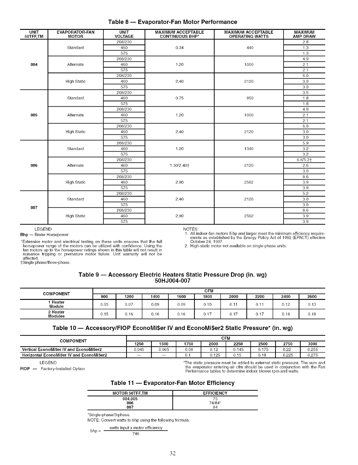
UNIT
50TFF, TM
OO4
005
006
OO7
EVAPORATOR-FAN
MOTOR
Standard
Alternate
High Static
Standard
Alternate
High Static
Standard
Alternate
High Static
Standard
High Static
Table 8 -- Evaporator-Fan Motor Performance
UNIT
VOLTAGE
208/230
46O
575
208/230
46O
575
208/230
48O
575
208/230
48O
575
208/230
48O
575
208/230
48O
575
208/230
48O
575
208/230
48O
575
208/230
48O
575
208/230
48O
575
208/230
48O
575
LEGEND
Bhp -- Brake Horsepower
*Extensive motor and electrical testing on these units ensures that the full
horsepower range of the motors can be utilized with confidence. Using the
fan motors up to the horsepower ratings shown in this table will not result in
nuisance tripping or premature motor failure. Unit warranty will not be
affected.
tSingle phase/three-phase.
MAXIMUM ACCEPTABLE
CONTINUOUS BHP*
0.34
1.20
2.40
0.75
1.20
2.40
1.20
1.30/2.40t
2.90
2.40
2.90
NOTES:
MAXIMUM ACCEPTABLE
OPERATING WATTS
44O
1000
2120
85O
1000
2120
1340
2120
2562
2120
2562
MAXIMUM
AMP DRAW
2.8
1.3
1.3
4.9
2.1
2.1
8.0
3.0
3.0
3.5
1.8
1.8
4.9
2.1
2.1
8.0
3.0
3.0
5.9
3.2
3.2
6.8/5.21-
2.8
3.0
8.8
3.9
3.9
5.2
3.0
3.0
8.8
3.9
3.9
1. All indoor-fan motors 5 hp and larger meet the minimum efficiency require-
ments as established by the Energy Policy Act of 1992 (EPACT) effective
October 24, 1997.
2. High-static motor not available on single-phase units.
Table 9 -- Accessory Electric Heaters Static Pressure Drop (in. wg)
50HJ004-007
COMPONENT
1 Heater
Module
2 Heater
Modules
900 1200 1400 1600 2000 2200 2400 2600
0.05 0.07 0.09 0.09 0.11 0.11 0.12 0.13
0.15 0.16 0.18 0.18 0.17 0.17 0.17 0.18 0.18
CFM
1800
0.10
Table 10- Accessory/FlOP EconoMi$er IV and EconoMi$er2 Static Pressure* (in. wg)
COMPONENT
Vertical EconoMi$er IV and EconoMi$er2
Horizontal EconoMi$er IV and EconoMiSer2
LEGEND
FlOP -- Factory-Installed Option
1250 1500
0.045 0.065
CFM
1750 2000 2250 I 2500 2750 3000
0.08 0.12 0.145 I0.175 0.22 0.255
0.1 0.125 0.15 0.18 0.225 0.275
*The static pressure must be added to external static pressure. The sum and
the evaporator entering-air cfm should be used in conjunction with the Fan
Per_rmance tables to determine indoor blower rpm and watts.
Table 11 -- Evaporator-Fan Motor Efficiency
MOTOR 50TFF, TM
004,005
OO6
OO7
*Sin gle-phase/3-phase.
NOTE: Convert watts to bhp using the following formula:
watts input x motor efficiency
bhp = 746
EFFICIENCY
75
74/84"
84
32
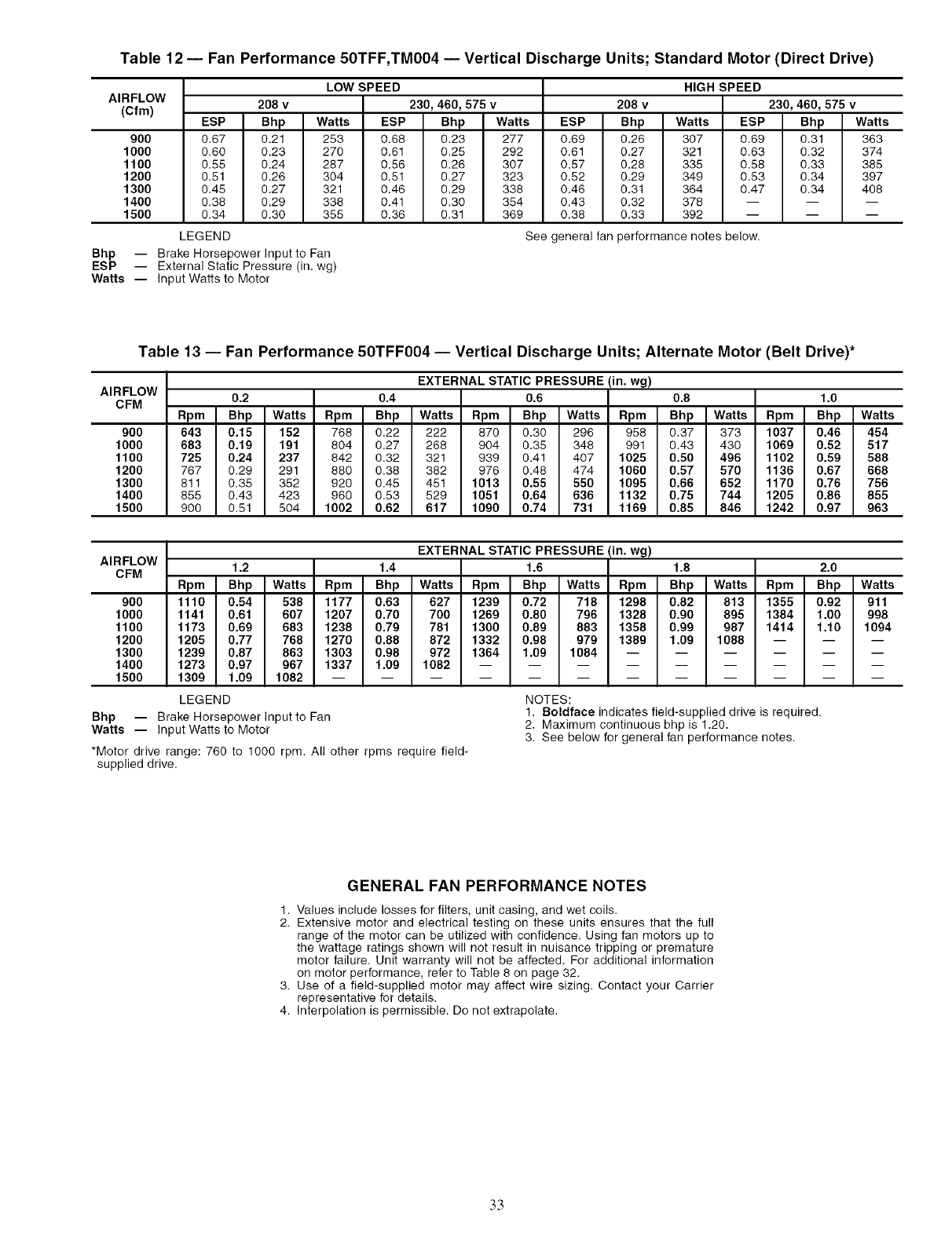
Table 12 -- Fan Performance 50TFF,TM004 -- Vertical Discharge Units; Standard Motor (Direct Drive)
AIRFLOW
(Cfm)
900
1000
1100
1200
1300
1400
1500
ESP
0.67
0.60
0.55
0.51
0.45
0.38
0.34
LEGEND
LOW SPEED
Bhp Watts ESP
0.28 307 0.69
0.27 321 0.63
0.28 335 0.58
0.29 349 0.53
0.31 364 0.47
0.32 378 --
0.33 392 --
208 v
Bhp Watts ESP Bhp Watts
0.21 253 0.68 0.23 277
0.23 270 0.61 0.25 292
0.24 287 0.56 0.26 307
0.26 304 0.51 0.27 323
0.27 321 0.46 0.29 338
0.29 338 0.41 0.30 354
0.30 355 0.36 0.31 369
HIGH SPEED
208 v 230, 460, 575 v
ESP Bhp Watts
0.69 0.31 363
0.61 0.32 374
0.57 0.33 385
0.52 0.34 397
0.48 0.34 408
0.43 -- --
0.38 -- --
230, 460, 575 v
See general fan performance notes below.
Bhp -- Brake Horsepower Input to Fan
ESP -- External Static Pressure (in. wg)
Watts -- Input Watts to Motor
Table 13 -- Fan Performance 50TFF004 -- Vertical Discharge Units; Alternate Motor (Belt Drive)*
AIRFLOW
CFM
9O0
1000
1100
1200
1300
1400
1500
EXTERNAL STATIC PRESSURE (in. wg)
0.2 0.4 0.6 0.8 1.0
Rpm Bhp Watts Rpm Bhp Watts Rpm Bhp Watts Rpm Bhp Watts Rpm Bhp Watts
643 0.15 152 768 0.22 222 870 0.30 296 958 0.37 373 1037 0.46 454
683 0.19 191 804 0.27 268 904 0.35 348 991 0.43 430 1069 0.52 517
725 0.24 237 842 0.32 321 939 0.41 407 1025 0.50 496 1102 0.59 588
767 0.29 291 880 0.38 382 976 0.48 474 1060 0.57 570 1136 0.67 668
811 0.35 352 920 0.45 451 1013 0.55 550 1095 0.66 652 1170 0.76 756
855 0.43 423 980 0.53 529 1051 0.64 636 1132 0.75 744 1205 0.86 855
900 0.51 504 1002 0.62 617 1090 0.74 731 1169 0.85 846 1242 0.97 963
AIRFLOW
CFM
9O0
1000
1100
1200
1300
1400
1500
Bhp -- Brake Horsepower Input to Fan
Watts -- Input Watts to Motor
*Motor drive range: 760 to 1000 rpm. All other rpms require field-
supplied drive.
EXTERNAL STATIC PRESSURE (in. wg)
1.2 1.4 1.6 1.8 2.0
Rpm Bhp Watts Rpm Bhp Watts Rpm Bhp Watts Rpm Bhp Watts Rpm Bhp Watts
1110 0.54 538 1177 0.63 627 1239 0.72 718 1298 0.82 813 1355 0.92 911
1141 0.61 607 1207 0.70 700 1269 0.80 796 1328 0.90 895 1384 1.00 998
1173 0.69 683 1238 0.79 781 1300 0.89 883 1358 0.99 987 1414 1.10 1094
1205 0.77 768 1270 0.88 872 1332 0.98 979 1389 1.09 1088 -- -- --
1239 0.87 863 1303 0.98 972 1364 1.09 1084 ......
1273 0.97 967 1337 1.09 1082 .........
1309 1.09 1082 ............
LEGEND NOTES:
1. Boldface indicates field-supplied drive is required.
2. Maximum continuous bhp is 1.20.
3. See below for general fan performance notes.
GENERAL FAN PERFORMANCE NOTES
1. Values include losses for filters, unit casing, and wet coils.
2. Extensive motor and electrical testing on these units ensures that the full
range of the motor can be utilized with confidence. Using fan motors up to
the wattage ratings shown will not result in nuisance tripping or premature
motor failure. Unit warranty will not be affected. For additional information
on motor performance, refer to Table 8 on page 32.
3. Use of a field-supplied motor may affect wire sizing. Contact your Carrier
representative for details.
4. Interpolation is permissible. Do not extrapolate.
33
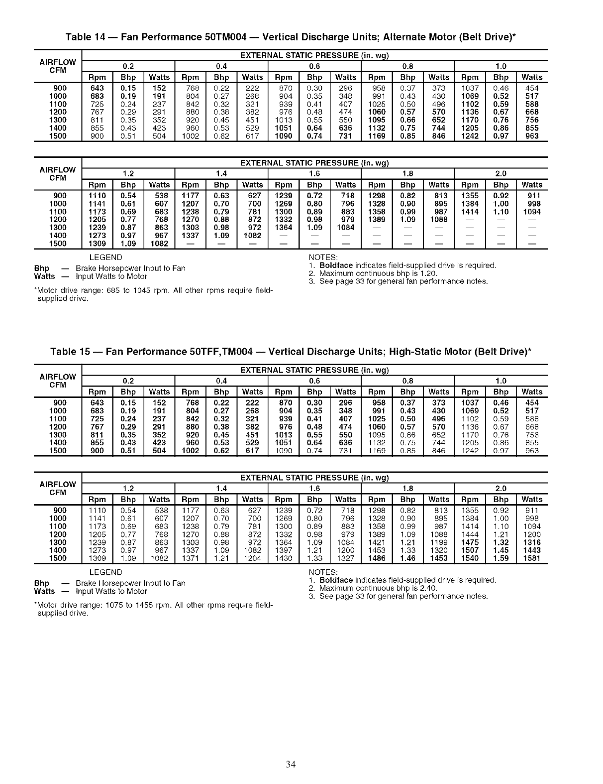
Table 14 -- Fan Performance 50TM004 -- Vertical Discharge Units; Alternate Motor (Belt Drive)*
AIRFLOW
CFM
900
1000
1100
1200
1300
1400
1500
EXTERNAL STATIC PRESSURE(in. wg)
0.2 0.4 0.6 0.8 1.0
Rpm Bhp Watts Rpm Bhp Watts Rpm Bhp Watts Rpm Bhp Watts Rpm Bhp Watts
643 0.15 152 768 0.22 222 870 0.30 296 958 0.37 373 1037 0.46 454
683 0.19 191 804 0.27 268 904 0.35 348 991 0.43 430 1069 0.52 517
725 0.24 237 842 0.32 321 939 0.41 407 1025 0.50 496 1102 0.59 588
767 0.29 291 880 0.38 382 976 0.48 474 1060 0.57 570 1136 0.67 668
811 0.35 352 920 0.45 451 1013 0.55 550 1095 0.66 652 1170 0.76 756
855 0.43 423 960 0.53 529 1051 0.64 636 1132 0.75 744 1205 0.86 855
900 0.51 504 1002 0.62 617 1090 0.74 731 1169 0.85 846 1242 0.97 963
AIRFLOW
CFM
900
1000
1100
1200
1300
1400
1500
Bhp -- Brake Horsepower Input to Fan
Watts -- Input Watts to Motor
EXTERNAL STATIC PRESSURE (in. wg)
1.2 1.4 1.6 1.8 2.0
Rpm Bhp Watts Rpm Bhp Watts Rpm Bhp Watts Rpm Bhp Watts Rpm Bhp Watts
1110 0.54 538 1177 0.63 627 1239 0.72 718 1298 0.82 813 1355 0.92 911
1141 0.61 607 1207 0.70 700 1269 0.80 796 1328 0.90 895 1384 1.00 998
1173 0.69 683 1238 0.79 781 1300 0.89 883 1358 0.99 987 1414 1.10 1094
1205 0.77 768 1270 0.88 872 1332 0.98 979 1389 1.09 1088 -- -- --
1239 0.87 863 1303 0.98 972 1364 1.09 1084 ......
1273 0.97 967 1337 1.09 1082 .........
1309 1.09 1082 ............
LEGEND NOTES:
1. Boldface indicates field-supplied drive is required,
2. Maximum continuous bhp is 1.20.
3. See page 33 for general fan performance notes.
*Motor drive range: 685 to 1045 rpm. All other rpms require field-
supplied drive.
Table 15 -- Fan Performance 50TFF,TM004 -- Vertical Discharge Units; High-Static Motor (Belt Drive)*
AIRFLOW
CFM
900
1000
1100
1200
1300
1400
1500
EXTERNAL STATIC PRESSURE (in. wg)
0.2 0.4 0.6 0.8 1.0
Rpm Bhp Watts Rpm Bhp Watts Rpm Bhp Watts Rpm Bhp Watts Rpm Bhp Watts
643 0.15 152 768 0.22 222 870 0.30 296 958 0.37 373 1037 0.46 454
683 0.19 191 804 0.27 268 904 0.35 348 991 0.43 430 1069 0.52 517
725 0.24 237 842 0.32 321 939 0.41 407 1025 0.50 496 1102 0.59 588
767 0.29 291 880 0.38 382 976 0.48 474 1060 0.57 570 1136 0.67 668
811 0.35 352 920 0.45 451 1013 0.55 550 1095 0.66 652 1170 0.76 756
855 0.43 423 960 0.53 529 1051 0.64 636 1132 0.75 744 1205 0.86 855
900 0.51 504 1002 0.62 617 1090 0.74 731 1169 0.85 846 1242 0.97 963
AIRFLOW
CFM
90O
1000
1100
1200
1300
1400
1500
Bhp -- Brake Horsepower Input to Fan
Watts -- Input Watts to Motor
*Motor drive range: 1075 to 1455 rpm. All other rpms require field-
supplied drive.
EXTERNAL STATIC PRESSURE (in. wg)
1.2 1.4 1.6 1.8 2.0
Rpm Bhp Watts Rpm Bhp Watts Rpm Bhp Watts Rpm Bhp Watts Rpm Bhp Watts
1110 0.54 538 1177 0.63 627 1239 0.72 718 1298 0.82 813 1355 0.92 911
1141 0.61 607 1207 0.70 700 1269 0.80 796 1328 0.90 895 1384 1.00 998
1173 0.69 683 1238 0.79 781 1300 0.89 883 1358 0.99 987 1414 1.10 1094
1205 0.77 768 1270 0.88 872 1332 0.98 979 1389 1.09 1088 1444 1.21 1200
1239 0.87 863 1303 0.98 972 1364 1.09 1084 1421 1.21 1199 1475 1.32 1316
1273 0.97 967 1337 1.09 1082 1397 1.21 1200 1453 1.33 1320 1507 1.45 1443
1309 1.09 1082 1371 1.21 1204 1430 1.33 1327 1486 1.46 1453 1540 1.59 1581
LEGEND NOTES:
1. Boldface indicates field-supplied drive is required.
2. Maximum continuous bhp is 2.40.
3. See page 33 for general fan performance notes.
34
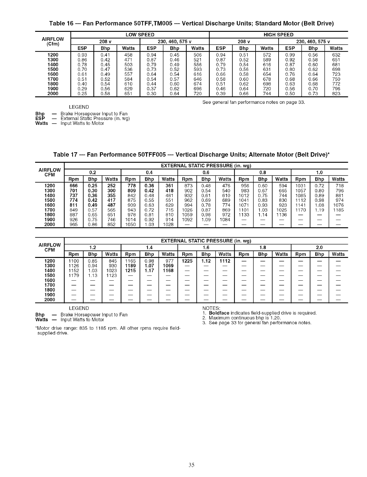
Table 16 -- Fan Performance 50TFF,TM005 -- Vertical Discharge Units; Standard Motor (Belt Drive)
AIRFLOW
(Cfm)
1200
1300
1400
1500
1600
1700
1800
1900
2000
LOW SPEED
208 v
ESP Bhp Watts ESP Bhp Watts
0.93 0.41 458 0.94 0.45 506
0.86 0.42 471 0.87 0.46 521
0.78 0.45 503 0.79 0.49 556
0.70 0.47 536 0.73 0.52 593
0.61 0.49 557 0.64 0.54 616
0.51 0.52 584 0.54 0.57 646
0.40 0.54 610 0.44 0.60 674
0.29 0.56 629 0.37 0.62 696
0.25 0.58 651 0.30 0.64 720
ESP
0.94 0.51
0.87 0.52
0.79 0.54
0.73 0.56
0.66 0.58
0.58 0.60
0.51 0.62
0.46 0.64
0.39 0.66
HIGH SPEED
208 v 230, 460, 575 v
Bhp Watts ESP Bhp Watts
572 0.99 0.56 632
589 0.92 0.58 651
616 0.87 0.60 681
631 0.80 0.62 698
654 0.76 0.64 723
678 0.68 0.66 750
698 0.63 0.68 772
720 0.56 0.70 796
744 0.50 0.73 823
See general fan performance notes on page 33.
LEGEND
230, 460, 575 v
Bhp -- Brake Horsepower Input to Fan
ESP -- External Static Pressure (in. wg)
Watts -- Input Watts to Motor
Table 17 -- Fan Performance 50TFF005 -- Vertical Discharge Units; Alternate Motor (Belt Drive)*
AIRFLOW
CFM
1200
1300
1400
1500
1600
1700
1800
1900
2000
EXTERNAL STATIC PRESSURE (in. wg)
0.2 0.4 0.6 0.8 1.0
Rpm Bhp Watts Rpm Bhp Watts Rpm Bhp Watts Rpm Bhp Watts Rpm Bhp Watts
666 0.25 252 778 0.36 361 873 0.48 476 956 0.60 594 1031 0.72 718
701 0.30 300 809 0.42 418 902 0.54 540 983 0.67 665 1057 0.80 796
737 0.36 355 842 0.48 481 932 0.61 610 1012 0.75 744 1085 0.89 881
774 0.42 417 875 0.55 551 962 0.69 689 1041 0.83 830 1112 0.98 974
811 0.49 487 909 0.63 629 994 0.78 774 1071 0.93 923 1141 1.08 1076
849 0.57 565 943 0.72 715 1026 0.87 869 1101 1.03 1025 1170 1.19 1185
887 0.65 651 978 0.81 810 1059 0.98 972 1133 1.14 1136 -- -- --
926 0.75 746 1014 0.92 914 1092 1.09 1084 ......
965 0.86 852 1050 1.03 1028 .........
AIRFLOW
CFM
1200
1300
1400
1500
1600
1700
1800
1900
2000
LEGEND
Bhp -- Brake Horsepower Input to Fan
Watts -- Input Watts to Motor
*Motor drive range: 835 to 1185 rpm. All other rpms require field-
supplied drive.
EXTERNAL STATIC PRESSURE (in. wg)
1.2 1.4 1.6 1.8 2.0
Rpm Bhp Watts Rpm Bhp Watts Rpm Bhp Watts Rpm Bhp Watts Rpm Bhp Watts
1100 0.85 845 1165 0.98 977 1225 1.12 1112 ......
1126 0.94 930 1189 1.07 1069 .........
1152 1.03 1023 1215 1.17 1168 .........
1179 1.13 1123 ............
NOTES:
1. Boldface indicates field-supplied drive is required.
2. Maximum continuous bhp is 1.20.
3. See page 33 for general fan performance notes.
.3.5
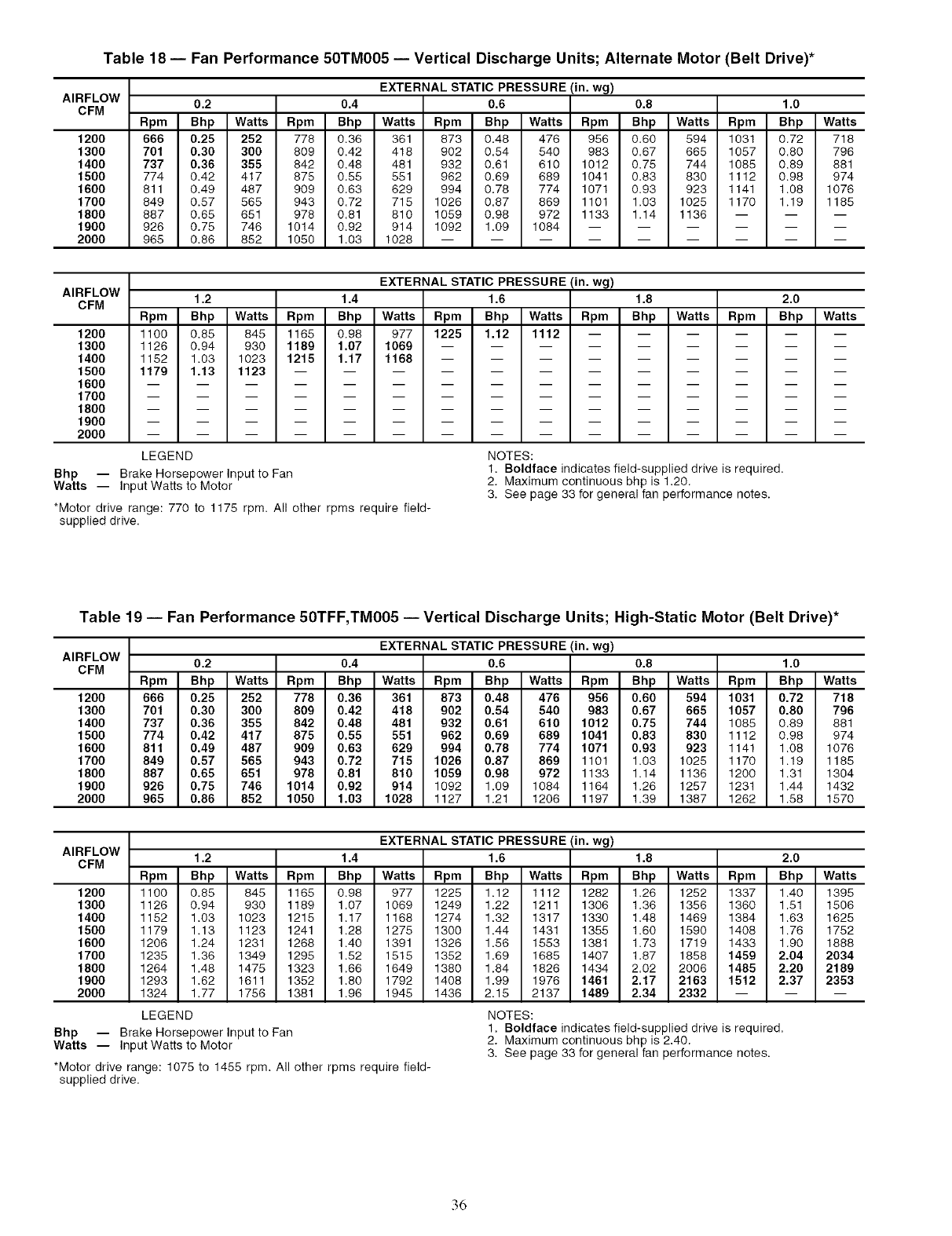
Table 18 -- Fan Performance 50TM005 -- Vertical Discharge Units; Alternate Motor (Belt Drive)*
AIRFLOW
CFM
1200
1300
1400
1500
1600
1700
1800
1900
2000
EXTERNAL STATIC PRESSURE (in. wg)
0.2 0.4 0.6 0.8 1.0
Rpm Bhp Watts Rpm Bhp Watts Rpm Bhp Watts Rpm Bhp Watts Rpm Bhp Watts
666 0.25 252 778 0.36 361 873 0.48 476 956 0.60 594 1031 0.72 718
701 0.30 300 809 0.42 418 902 0.54 540 983 0.67 665 1057 0.80 796
737 0.36 355 842 0.48 481 932 0.61 610 1012 0.75 744 1085 0.89 881
774 0.42 417 875 0.55 551 962 0.69 689 1041 0.83 830 1112 0.98 974
811 0.49 487 909 0.63 629 994 0.78 774 1071 0.93 923 1141 1.08 1076
849 0.57 565 943 0.72 715 1026 0.87 869 1101 1.03 1025 1170 1.19 1185
887 0.65 651 978 0.81 810 1059 0.98 972 1133 1.14 1136 -- -- --
926 0.75 746 1014 0.92 914 1092 1.09 1084 ......
965 0.86 852 1050 1.03 1028 .........
AIRFLOW
CFM
1200
1300
1400
1500
1600
1700
1800
1900
2000
LEGEND
Bhp -- Brake Horsepower Input to Fan
Watts -- Input Watts to Motor
*Motor drive range: 770 to 1175 rpm. All other rpms require field-
supplied drive.
EXTERNAL STATIC PRESSURE(in. wg)
1.2 1.4 1.6 1.8 2.0
Rpm Bhp Watts Rpm Bhp Watts Rpm Bhp Watts Rpm Bhp Watts Rpm Bhp Watts
1100 0.85 845 1165 0.98 977 1225 1.12 1112 ......
1126 0.94 930 1189 1.07 1069 .........
1152 1.03 1023 1215 1.17 1168 .........
1179 1.13 1123 ............
NOTES:
1. Boldface indicates field-supplied drive is required.
2. Maximum continuous bhp is 1.20.
3. See page 33 for general fan performance notes.
Table 19 -- Fan Performance 50TFF,TM005 -- Vertical Discharge Units; High-Static Motor (Belt Drive)*
AIRFLOW
CFM
1200
1300
1400
1500
1600
1700
1800
1900
2000
EXTERNAL STATIC PRESSURE(in. wg)
0.2 0.4 0.6 0.8 1.0
Rpm Bhp Watts Rpm Bhp Watts Rpm Bhp Wa_s Rpm Bhp Watts Rpm Bhp Watts
666 0.25 252 778 0.36 361 873 0.48 476 956 0.60 594 1031 0.72 718
701 0.30 300 809 0.42 418 902 0.54 540 983 0.67 665 1057 0.80 796
737 0.36 355 842 0.48 481 932 0.61 610 1012 0.75 744 1085 0.89 881
774 0.42 417 875 0.55 551 962 0.69 689 1041 0.83 830 1112 0.98 974
811 0.49 487 909 0.63 629 994 0.78 774 1071 0.93 923 1141 1.08 1076
849 0.57 565 943 0.72 715 1026 0.87 869 1101 1.03 1025 1170 1.19 1185
887 0.65 651 978 0.81 810 1059 0.98 972 1133 1.14 1136 1200 1.31 1304
926 0.75 746 1014 0.92 914 1092 1.09 1084 1164 1.26 1257 1231 1.44 1432
965 0.86 852 1050 1.03 1028 1127 1.21 1206 1197 1.39 1387 1262 1.58 1570
AIRFLOW
CFM
1200
1300
1400
1500
1600
1700
1800
1900
2000
Bhp -- Brake Horsepower Input to Fan
Watts -- Input Watts to Motor
*Motor drive range: 1075 to 1455 rpm. All other rpms require field-
supplied drive.
EXTERNAL STATIC PRESSURE (in. wg)
1.2 1.4 1.6 1.8 2.0
Rpm Bhp Watts Rpm Bhp Watts Rpm Bhp Watts Rpm Bhp Watts Rpm Bhp Watts
1100 0.85 845 1165 0.98 977 1225 1.12 1112 1282 1.26 1252 1337 1.40 1395
1126 0.94 930 1189 1.07 1069 1249 1.22 1211 1306 1.36 1356 1360 1.51 1506
1152 1.03 1023 1215 1.17 1168 1274 1.32 1317 1330 1.48 1469 1384 1.63 1625
1179 1.13 1123 1241 1.28 1275 1300 1.44 1431 1355 1.60 1590 1408 1.76 1752
1206 1.24 1231 1268 1.40 1391 1326 1.56 1553 1381 1.73 1719 1433 1.90 1888
1235 1.36 1349 1295 1.52 1515 1352 1.69 1685 1407 1.87 1858 1459 2.04 2034
1264 1.48 1475 1323 1.66 1649 1380 1.84 1826 1434 2.02 2006 1485 2.20 2189
1293 1.62 1611 1352 1.80 1792 1408 1.99 1976 1461 2.17 2163 1512 2.37 2353
1324 1.77 1756 1381 1.96 1945 1436 2.15 2137 1489 2.34 2332 -- -- --
LEGEND NOTES:
1. Boldface indicates field-supplied drive is required.
2. Maximum continuous bhp is 2.40.
3. See page 33 for general fan performance notes.
36
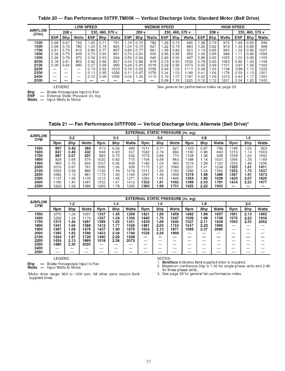
Table 20 -- Fan Performance 50TFF,TM006 -- Vertical Discharge Units; Standard Motor (Belt Drive)
AIRFLOW
(Cfm)
1500
1600
1700
1800
1900
2000
2100
2200
2300
2400
2500
LOW SPEED
208 v 230, 460, 575 v
ESP Bhp Watts ESP Bhp Watts
0.88 0.67 750 1.20 0.71 791
0.68 0.70 780 1.04 0.74 824
0.51 0.73 810 0.89 0.77 857
0.35 0.75 839 0.73 0.80 891
0.26 0.78 873 0.58 0.83 924
0.18 0.81 905 0.42 0.88 957
0.08 0.84 940 0.27 0.89 990
0.19 0.92 1023
0.11 0.95 1056
0.03 0.98 1096
LEGEND
MEDIUM SPEED
208 v 230, 460, 575 v
ESP Bhp Watts ESP Bhp Watts
1.19 0.70 782 1.36 0.76 845
1.04 0.74 821 1.22 0.79 883
0.89 0.77 881 1.09 0.83 921
0.74 0.81 900 0.98 0.86 959
0.59 0.84 940 0.86 0.90 997
0.44 0.88 979 0.73 0.93 1035
0.29 0.91 1018 0.59 0.96 1073
0.19 0.93 1035 0.48 1.00 1111
0.11 0.97 1076 0.34 1.03 1149
0.04 1.00 1113 0.19 1.07 1187
-- -- -- 0.09 1.10 1225
HIGH SPEED
208 v 230, 460, 575 v
ESP Bhp Watts ESP Bhp Watts
1.38 0.79 875 1.44 0.85 949
1.25 0.82 913 1.33 0.89 988
1.13 0.85 950 1.22 0.92 1027
1.00 0.89 988 1.11 0.98 1068
0.88 0.92 1025 1.00 0.99 1105
0.78 0.95 1063 0.92 1.03 1144
0.63 0.99 1101 0.81 1.08 1183
0.49 1.02 1138 0.69 1.10 1222
0.41 1.06 1178 0.59 1.13 1261
0.22 1.09 1213 0.43 1.17 1300
0.12 1.12 1251 0.34 1.20 1340
See general fan performance notes on page 33.
Bhp -- Brake Horsepower Input to Fan
ESP -- External Static Pressure (in. wg)
Watts -- Input Watts to Motor
Table 21 -- Fan Performance 50TFF006 -- Vertical Discharge Units; Alternate (Belt Drive)*
AIRFLOW
CFM
1500
1600
1700
1800
1900
2000
2100
2200
2300
2400
2500
EXTERNAL STATIC PRESSURE (in. wg)
0.2 0.4 0.6 0.8 1.0
Rpm Bhp Watts Rpm Bhp Watts Rpm Bhp Watts Rpm Bhp Watts Rpm Bhp Watts
807 0.42 369 913 0.56 489 1011 0.71 621 1103 0.87 766 1188 1.05 923
847 0.49 432 948 0.63 557 1042 0.79 694 1130 0.96 843 1213 1.14 1003
887 0.57 501 983 0.72 632 1073 0.88 774 1158 1.08 928 1239 1.24 1092
928 0.68 579 1020 0.82 715 1106 0.98 883 1188 1.18 1021 1288 1.35 1189
989 0.78 688 1057 0.92 808 1140 1.09 980 1219 1.28 1123 1295 1.48 1296
1010 0.87 761 1095 1.04 909 1175 1.21 1088 1251 1.41 1234 1325 1.61 1411
1052 0.99 888 1133 1.16 1019 1211 1.35 1182 1285 1.54 1355 1355 1.75 1537
1095 1.12 981 1173 1.30 1140 1247 1.49 1308 1319 1.69 1486 1387 1.91 1673
1137 1.28 1105 1212 1.45 1271 1284 1.65 1445 1353 1.85 1628 1420 2.07 1820
1180 1.41 1241 1252 1.61 1412 1322 1.81 1592 1389 2.03 1781 1454 2.25 1977
1223 1.58 1388 1293 1.78 1565 1360 1.99 1751 1425 2.22 1945 -- -- --
AIRFLOW
CFM
1500
1600
1700
1800
1900
2000
2100
2200
2300
2400
2500
EXTERNAL STATIC PRESSURE (in. wg)
1.2 1.4 1.6 1.8 2.0
Rpm Bhp Watts Rpm Bhp Watts Rpm Bhp Watts Rpm Bhp Watts Rpm Bhp Watts
1270 1.24 1091 1347 1.45 1269 1421 1.66 1458 1492 1.89 1657 1561 2.13 1865
1292 1.34 1174 1367 1.54 1356 1440 1.76 1547 1509 1.99 1748 1576 2.23 1959
1315 1.44 1267 1389 1.65 1451 1459 1.88 1646 1527 2.11 1849 1593 2.35 2062
1341 1.56 1368 1412 1.77 1556 1481 2.00 1753 1547 2.23 1960 -- -- --
1367 1.68 1478 1437 1.90 1670 1504 2.13 1871 1569 2.37 2080 -- -- --
1395 1.82 1598 1463 2.04 1794 1528 2.28 1998 ......
1424 1.97 1728 1490 2.20 1928 .........
1454 2.13 1869 1518 2.36 2073 .........
1485 2.30 2020 ............
LEGEND
Bhp -- Brake Horsepower Input to Fan
Watts -- Input Watts to Motor
*Motor drive range: 900 to 1300 rpm. All other rpms require field-
supplied drive.
NOTES:
1. Boldface indicates field-supplied drive is required.
2. Maximum continuous bhp is 1.30 for single-phase units and 2.40
for three-phase units.
3. See page 33 for general fan performance notes.
37
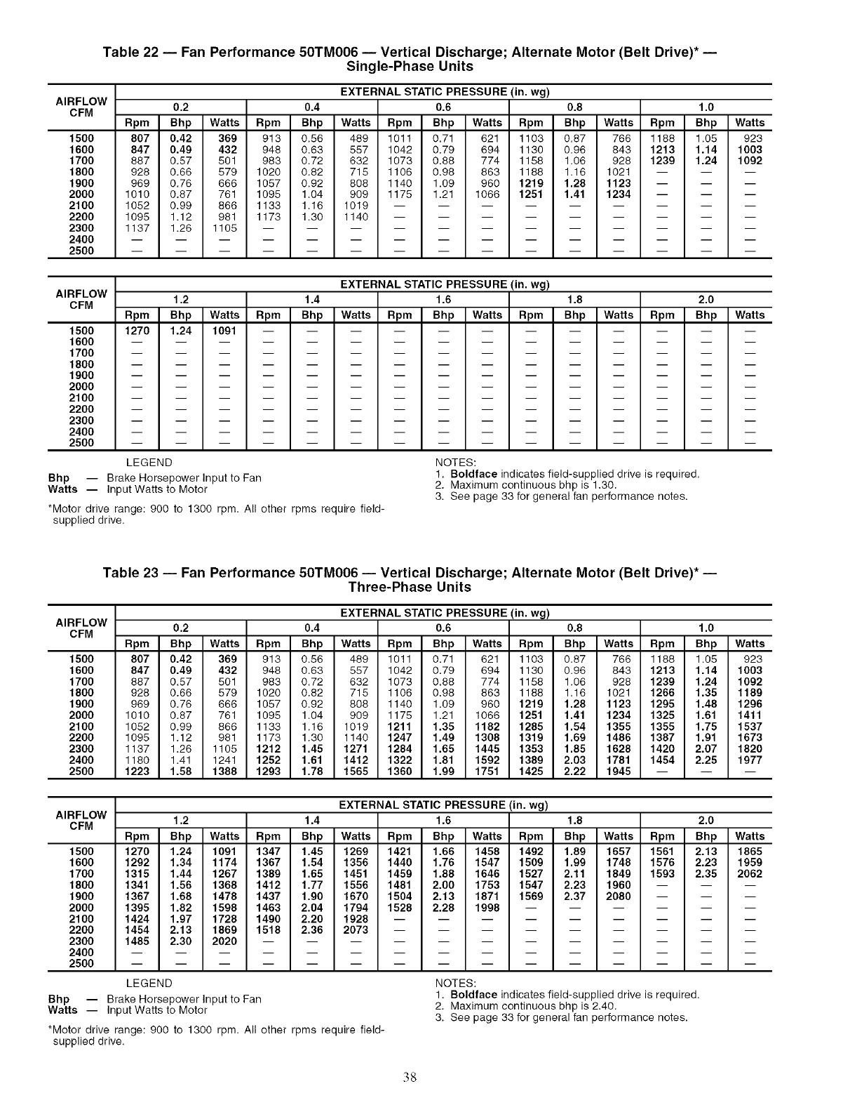
Table 22 -- Fan Performance 50TM006 -- Vertical Discharge; Alternate Motor (Belt Drive)* --
Single-Phase Units
AIRFLOW
CFM
1500
1600
1700
1800
1900
2000
2100
2200
2300
2400
2500
EXTERNAL STATIC PRESSURE (in. wg)
0.2 0.4 0.6 0.8 1.0
Rpm Bhp Watts Rpm Bhp Watts Rpm Bhp Watts Rpm Bhp Watts Rpm Bhp Watts
807 0.42 369 913 0.56 489 1011 0.71 621 1103 0.87 766 1188 1.05 923
847 0.49 432 948 0.63 557 1042 0.79 694 1130 0.96 843 1213 1.14 1003
887 0.57 501 983 0.72 632 1073 0.88 774 1158 1.06 928 1239 1.24 1092
928 0.66 579 1020 0.82 715 1106 0.98 863 1188 1.16 1021 -- -- --
969 0.76 666 1057 0.92 808 1140 1.09 960 1219 1.28 1123 -- -- --
1010 0.87 761 1095 1.04 909 1175 1.21 1066 1251 1.41 1234 -- -- --
1052 0.99 866 1133 1.16 1019 .........
1098 1.12 981 1173 1.30 1140 .........
1137 1.26 1105 ............
AIRFLOW
CFM
1500
1600
1700
1800
1900
2000
2100
2200
2300
2400
2500
EXTERNAL STATIC PRESSURE (in. wg)
1.2 1.4 1.6 1.8 2.0
Rpm Bhp Watts Rpm Bhp Watts Rpm Bhp Watts Rpm Bhp Watts Rpm Bhp Watts
1270 1.24 1091 ....
m m
m m
m m
m m
m m
m m
m m
m m
m m
m m
m
m
m
m
m
m
m
m
m
m
m
m
m
m
m
m
m
m
m
m
m m
m m
m m
m m
m m
m m
m m
m m
m m
m m
LEGEND
Bhp -- Brake Horsepower Input to Fan
Watts -- Input Watts to Motor
*Motor drive range: 900 to 1300 rpm. All other rpms require field-
supplied drive.
NOTES:
1. Boldface indicates field-supplied drive is required.
2. Maximum continuous bhp is 1.30.
3. See page 33 for general fan performance notes.
Table 23 -- Fan Performance 50TM006 -- Vertical Discharge; Alternate Motor (Belt Drive)* --
Three-Phase Units
AIRFLOW
CFM
1500
1600
1700
1800
1900
2000
2100
2200
2300
2400
2500
EXTERNAL STATIC PRESSURE (in. wg)
0.2 0.4 0.6 0.8 1.0
Rpm Bhp Watts Rpm Bhp Watts Rpm Bhp Watts Rpm Bhp Watts Rpm Bhp Watts
807 0.42 369 913 0.56 489 1011 0.71 621 1103 0.87 766 1188 1.05 923
847 0.49 432 948 0.63 557 1042 0.79 694 1130 0.96 843 1213 1.14 1003
887 0.57 501 983 0.72 632 1073 0.88 774 1158 1.06 928 1239 1.24 1092
928 0.66 579 1020 0.82 715 1106 0.98 863 1188 1.16 1021 1266 1.35 1189
969 0.76 666 1057 0.92 808 1140 1.09 960 1219 1.28 1123 1295 1.48 1296
1010 0.87 761 1095 1.04 909 1175 1.21 1066 1251 1.41 1234 1325 1.61 1411
1052 0.99 866 1133 1.16 1019 1211 1.35 1182 1285 1.54 1355 1355 1.75 1537
1095 1.12 981 1173 1.30 1140 1247 1.49 1308 1319 1.69 1486 1387 1.91 1673
1137 1.26 1105 1212 1.45 1271 1284 1.65 1445 1353 1.85 1628 1420 2.07 1820
1180 1.41 1241 1252 1.61 1412 1322 1.81 1592 1389 2.03 1781 1454 2.25 1977
1223 1.58 1388 1293 1.78 1565 1360 1.99 1751 1425 2.22 1945 -- -- --
AIRFLOW
CFM
1500
1600
1700
1800
1900
2000
2100
2200
2300
2400
2500
LEGEND
Bhp -- Brake Horsepower Input to Fan
Watts -- Input Watts to Motor
*Motor drive range: 900 to 1300 rpm. All other rpms require field-
supplied drive.
EXTERNAL STATIC PRESSURE (in. wg)
1.2 1.4 1.6 1.8 2.0
Rpm Bhp Watts Rpm Bhp Watts Rpm Bhp Watts Rpm Bhp Watts Rpm Bhp Watts
1270 1.24 1091 1347 1.45 1269 1421 1.66 1458 1492 1.89 1657 1561 2.13 1865
1292 1.34 1174 1367 1.54 1356 1440 1.76 1547 1509 1.99 1748 1576 2.23 1959
1315 1.44 1267 1389 1.65 1451 1459 1.88 1646 1527 2.11 1849 1593 2.35 2062
1341 1.56 1368 1412 1.77 1556 1481 2.00 1753 1547 2.23 1960 -- -- --
1367 1.68 1478 1437 1.90 1670 1504 2.13 1871 1569 2.37 2080 -- -- --
1395 1.82 1598 1463 2.04 1794 1528 2.28 1998 ......
1424 1.97 1728 1490 2.20 1928 .........
1454 2.13 1869 1518 2.36 2073 .........
1485 2.30 2020 ............
NOTES:
1. Boldface indicates field-supplied drive is required,
2. Maximum continuous bhp is 2,40.
3. See page 33 for general fan performance notes.
38
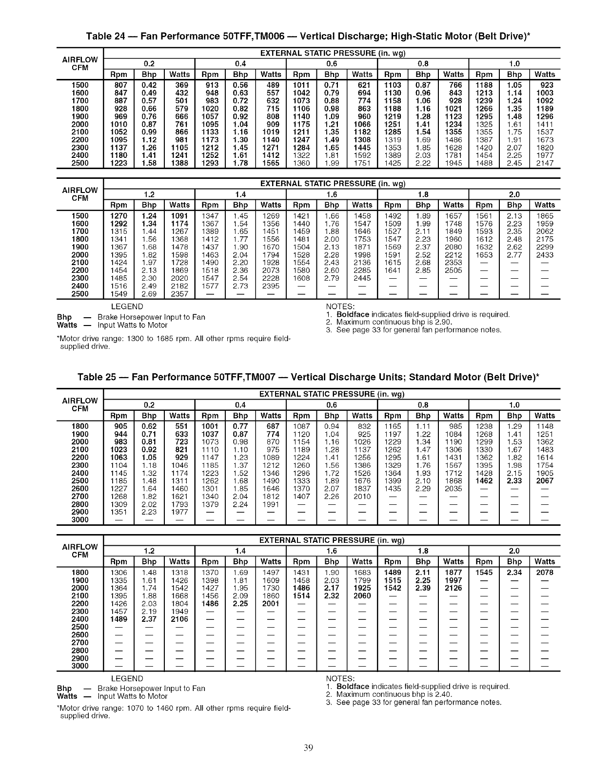
Table 24 -- Fan Performance 50TFF,TM006 -- Vertical Discharge; High-Static Motor (Belt Drive)*
AIRFLOW
CFM
1500
1600
1700
1800
1900
2000
2100
2200
2300
2400
2500
EXTERNAL STATIC PRESSURE (in. wg)
0.2 0.4 0.6 0.8 1.0
Rpm Bhp Watts Rpm Bhp Watts Rpm Bhp Watts Rpm Bhp Watts Rpm Bhp Watts
807 0.42 369 913 0.56 489 1011 0.71 621 1103 0.87 766 1188 1.05 923
847 0.49 432 948 0.63 557 1042 0.79 694 1130 0.96 843 1213 1.14 1003
887 0.57 501 983 0.72 632 1073 0.88 774 1158 1.06 928 1239 1.24 1092
928 0.66 579 1020 0.82 715 1106 0.98 863 1188 1.16 1021 1266 1.35 1189
969 0.76 666 1057 0.92 808 1140 1.09 960 1219 1.28 1123 1295 1.48 1296
1010 0.87 761 1095 1.04 909 1175 1.21 1066 1251 1.41 1234 1325 1.81 1411
1052 0.99 866 1133 1.16 1019 1211 1.35 1182 1285 1.54 1355 1355 1.75 1537
1095 1.12 981 1173 1.30 1140 1247 1.49 1308 1319 1.69 1486 1387 1.91 1673
1137 1.26 1105 1212 1.45 1271 1284 1.65 1445 1353 1.85 1628 1420 2.07 1820
1180 1.41 1241 1252 1.61 1412 1322 1.81 1592 1389 2.03 1781 1454 2.25 1977
1223 1.58 1388 1293 1.78 1565 1360 1.99 1751 1425 2.22 1945 1488 2.45 2147
AIRFLOW
CFM
1500
1600
1700
1800
1900
2000
2100
2200
2300
2400
2500
Bhp -- Brake Horsepower Input to Fan
Watts -- Input Watts to Motor
*Motor drive range: 1300 to 1685 rpm. All other rpms require field-
supplied drive.
EXTERNAL STATIC PRESSURE (in. wg)
1.2 1.4 1.6 1.8 2.0
Rpm Bhp Watts Rpm Bhp Watts Rpm Bhp Watts Rpm Bhp Watts Rpm Bhp Watts
1270 1.24 1091 1347 1.45 1269 1421 1.68 1458 1492 1.89 1657 1561 2.13 1865
1292 1.34 1174 1367 1.54 1356 1440 1.78 1547 1509 1.99 1748 1576 2.23 1959
1315 1.44 1267 1389 1.85 1451 1459 1.88 1648 1527 2.11 1849 1593 2.35 2062
1341 1.58 1368 1412 1.77 1558 1481 2.00 1753 1547 2.23 1960 1612 2.48 2175
1367 1.68 1478 1437 1.90 1670 1504 2.13 1871 1569 2.37 2080 1632 2.62 2299
1395 1.82 1598 1463 2.04 1794 1528 2.28 1998 1591 2.52 2212 1653 2.77 2433
1424 1.97 1728 1490 2.20 1928 1554 2.43 2136 1615 2.68 2353 -- -- --
1454 2.13 1869 1518 2.36 2073 1580 2.60 2285 1641 2.85 2505 -- -- --
1485 2.30 2020 1547 2.54 2228 1608 2.79 2445 ......
1516 2.49 2182 1577 2.73 2395 .........
1549 2.69 2357 ............
LEGEND NOTES:
1. Boldface indicates field-supplied drive is required.
2. Maximum continuous bhp is 2.90.
3. See page 33 for general fan performance notes.
Table 25 -- Fan Performance 50TFF,TM007 -- Vertical Discharge Units; Standard Motor (Belt Drive)*
AIRFLOW
CFM
1800
1900
2000
2100
2200
2300
2400
2500
2600
2700
2800
2900
3000
EXTERNAL STATIC PRESSURE (in. wg)
0.2 0.4 0.6 0.8 1.0
Rpm Bhp Watts Rpm Bhp Watts Rpm Bhp Watts Rpm Bhp Watts Rpm Bhp Watts
905 0.62 551 1001 0.77 687 1087 0.94 832 1165 1.11 985 1238 1.29 1148
944 0.71 633 1037 0.87 774 1120 1.04 925 1197 1.22 1084 1268 1.41 1251
983 0.81 723 1073 0.98 870 1154 1.18 1028 1229 1.34 1190 1299 1.53 1362
1023 0.92 821 1110 1.10 975 1189 1.28 1137 1262 1.47 1308 1330 1.67 1483
1063 1.05 929 1147 1.23 1089 1224 1.41 1258 1295 1.61 1431 1362 1.82 1614
1104 1.18 1048 1185 1.37 1212 1260 1.58 1388 1329 1.76 1567 1395 1.98 1754
1145 1.32 1174 1223 1.52 1348 1296 1.72 1528 1364 1.93 1712 1428 2.15 1905
1185 1.48 1311 1262 1.68 1490 1333 1.89 1678 1399 2.10 1888 1462 2.33 2067
1227 1.64 1460 1301 1.85 1646 1370 2.07 1837 1435 2.29 2035 -- -- --
1268 1.82 1621 1340 2.04 1812 1407 2.26 2010 ......
1309 2.02 1793 1379 2.24 1991 .........
1351 2.23 1977 ............
AIRFLOW
CFM
1800
1900
2000
2100
2200
2300
2400
2500
2600
2700
2800
2900
3000
EXTERNAL STATIC PRESSURE (in. wg)
1.2 1.4 1.6 1.8 2.0
Rpm Bhp Watts Rpm Bhp Watts Rpm Bhp Watts Rpm Bhp Watts Rpm Bhp Watts
1306 1.48 1318 1370 1.69 1497 1431 1.90 1683 1489 2.11 1877 1545 2.34 2078
1335 1.61 1426 1398 1.81 1609 1458 2.03 1799 1515 2.25 1997 --
1364 1.74 1542 1427 1.95 1730 1486 2.17 1925 1542 2.39 2126 --
1395 1.88 1668 1456 2.09 1860 1514 2.32 2060 --
m m
m m
1426 2.03 1804 1486 2.25 2001 .........
1457 2.19 1949 ............
1489 2.37 2106 ............
LEGEND
Bhp -- Brake Horsepower Input to Fan
Watts -- Input Watts to Motor
*Motor drive range: 1070 to 1460 rpm. All other rpms require field-
supplied drive.
NOTES:
1. Boldface indicates field-supplied drive is required.
2. Maximum continuous bhp is 2.40.
3. See page 33 for general fan performance notes.
39
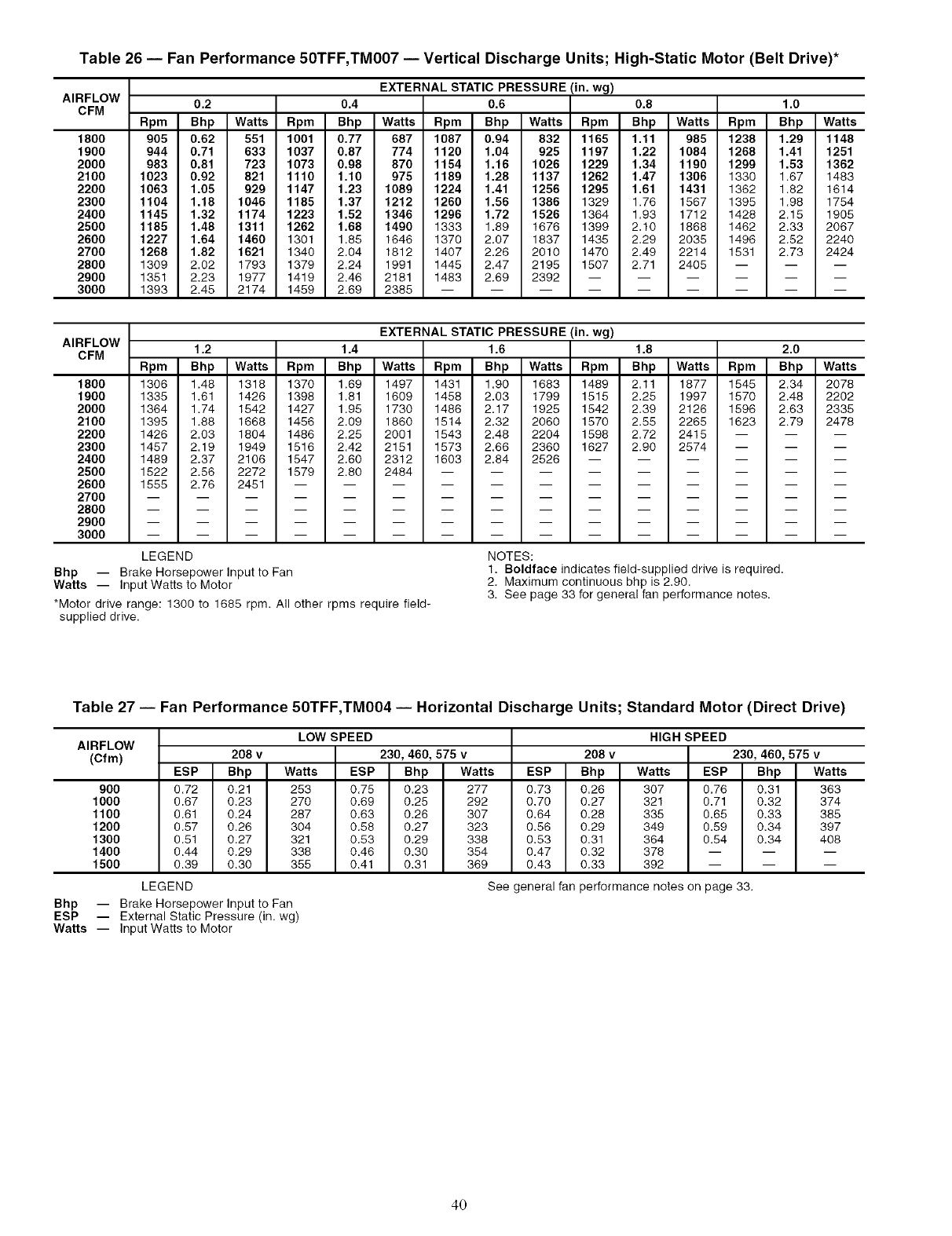
Table 26 -- Fan Performance 50TFF,TM007 -- Vertical Discharge Units; High-Static Motor (Belt Drive)*
AIRFLOW
CFM
1800
1900
2000
2100
2200
2300
2400
2500
2600
2700
2800
2900
3000
EXTERNAL STATIC PRESSURE (in. wg)
0.2 0.4 0.6 0.8 1.0
Rpm Bhp Watts Rpm Bhp Watts Rpm Bhp Watts Rpm Bhp Watts Rpm Bhp Watts
905 0.62 551 1001 0.77 687 1087 0.94 832 1165 1.11 985 1238 1.29 1148
944 0.71 633 1037 0.87 774 1120 1.04 925 1197 1.22 1084 1268 1.41 1251
983 0.81 723 1073 0.98 870 1154 1.16 1026 1229 1.34 1190 1299 1.53 1362
1023 0.92 821 1110 1.10 975 1189 1.28 1137 1262 1.47 1306 1330 1.67 1483
1063 1.05 929 1147 1.23 1089 1224 1.41 1256 1295 1.61 1431 1362 1.82 1614
1104 1.18 1046 1185 1.37 1212 1260 1.56 1386 1329 1.76 1567 1395 1.98 1754
1145 1.32 1174 1223 1.52 1346 1296 1.72 1526 1364 1.93 1712 1428 2.15 1905
1185 1.48 1311 1262 1.68 1490 1333 1.89 1676 1399 2.10 1868 1462 2.33 2067
1227 1.64 1460 1301 1.85 1646 1370 2.07 1837 1435 2.29 2035 1496 2.52 2240
1268 1.82 1621 1340 2.04 1812 1407 2.26 2010 1470 2.49 2214 1531 2.73 2424
1309 2.02 1793 1379 2.24 1991 1445 2.47 2195 1507 2.71 2405 -- -- --
1351 2.23 1977 1419 2.46 2181 1483 2.69 2392 ......
1393 2.45 2174 1459 2.69 2385 .........
AIRFLOW
CFM
1800
1900
2000
2100
2200
2300
2400
2500
2600
2700
2800
2900
3000
EXTERNAL STATIC PRESSURE (in. wg)
1.2 1.4 1.6 1.8 2.0
Rpm Bhp Watts Rpm Bhp Watts Rpm Bhp Watts Rpm Bhp Watts Rpm Bhp Watts
1306 1.48 1318 1370 1.69 1497 1431 1.90 1683 1489 2.11 1877 1545 2.34 2078
1336 1.61 1426 1398 1.81 1609 1458 2.03 1799 1515 2.25 1997 1570 2.48 2202
1364 1.74 1542 1427 1.95 1730 1486 2.17 1925 1542 2.39 2126 1596 2.63 2335
1395 1.88 1668 1456 2.09 1860 1514 2.32 2060 1570 2.55 2265 1623 2.79 2478
1426 2.03 1804 1486 2.25 2001 1543 2.48 2204 1598 2.72 2415 -- -- --
1457 2.19 1949 1516 2.42 2151 1573 2.66 2360 1627 2.90 2574 -- -- --
1489 2.37 2106 1547 2.60 2312 1603 2.84 2526 ......
1522 2.56 2272 1579 2.80 2484 .........
1555 2.76 2451 ............
LEGEND
Bhp -- Brake Horsepower Input to Fan
Watts -- Input Watts to Motor
*Motor drive range: 1300 to 1685 rpm. All other rpms require field-
supplied drive.
NOTES:
1. Boldface indicates field-supplied drive is required.
2. Maximum continuous bhp is 2.90.
3. See page 33 for general fan performance notes.
Table 27 -- Fan Performance 50TFF,TM004 -- Horizontal Discharge Units; Standard Motor (Direct Drive)
AIRFLOW
(Cfm)
900
1000
1100
1200
1300
1400
1500
LOW SPEED
208 v 230, 460, 575 v
ESP Bhp Watts ESP Bhp Watts
0.72 0.21
0.67 0.23
0.61 0.24
0.57 0.26
0.51 0.27
0.44 0.29
0.39 0.30
LEGEND
253 0.75 0.23 277
270 0.69 0.25 292
287 0.63 0.26 307
304 0.58 0.27 323
321 0.53 0.29 338
338 0.46 0.30 354
355 0.41 0.31 369
208 v
ESP Bhp Watts
0.73 0.26 307 0.76 0.31
0.70 0.27 321 0.71 0.32
0.64 0.28 335 0.65 0.33
0.56 0.29 349 0.59 0.34
0.53 0.31 364 0.54 0.34
0.47 0.32 378 -- --
0.43 0.33 392 -- --
See general _n performance notes on page 33.
HIGH SPEED
230, 460, 575 v
ESP Bhp Watts
363
374
385
397
408
Bhp -- Brake Horsepower Input to Fan
ESP -- External Static Pressure (in. wg)
Watts -- Input Watts to Motor
4O
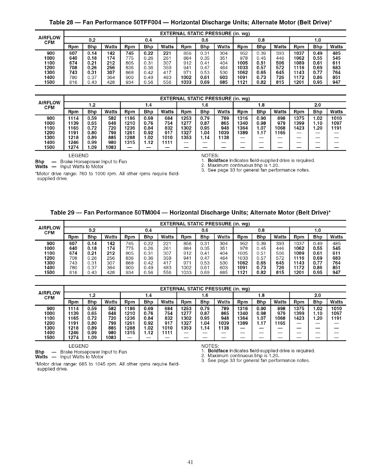
Table 28 -- Fan Performance 50TFF004 -- Horizontal Discharge Units; Alternate Motor (Belt Drive)*
AIRFLOW
CFM
9O0
1000
1100
1200
1300
1400
1500
EXTERNAL STATIC PRESSURE (in. wg)
0.2 0.4 0.6 0.8 1.0
Rpm Bhp Watts Rpm Bhp Watts Rpm Bhp Watts Rpm Bhp Watts Rpm Bhp Watts
607 0.14 142 745 0.22 221 856 0.31 304 952 0.39 393 1037 0.49 485
640 0.18 174 775 0.26 261 884 0.35 351 978 0.45 446 1062 0.55 545
674 0.21 212 805 0.31 307 912 0.41 404 1005 0.51 506 1089 0.61 611
708 0.26 256 836 0.36 359 941 0.47 464 1033 0.57 572 1116 0.69 683
743 0.31 307 868 0.42 417 971 0.53 530 1062 0.65 645 1143 0.77 764
780 0.37 364 900 0.49 483 1002 0.61 603 1091 0.73 726 1172 0.86 851
816 0.43 428 934 0.56 556 1033 0.69 685 1121 0.82 815 1201 0.95 947
AIRFLOW
CFM
9OO
1000
1100
1200
1300
1400
1500
Bhp -- Brake Horsepower Input to Fan
Watts -- Input Watts to Motor
*Motor drive range: 760 to 1000 rpm. All other rpms require field-
supplied drive.
EXTERNAL STATIC PRESSURE (in. wg)
1.2 1.4 1.6 1.8 2.0
Rpm Bhp Watts Rpm Bhp Watts Rpm Bhp Watts Rpm Bhp Watts Rpm Bhp Watts
1114 0.59 582 1186 0.69 684 1253 0.79 789 1316 0.90 898 1375 1.02 1010
1139 0.65 648 1210 0.76 754 1277 0.87 865 1340 0.98 979 1399 1.10 1097
1165 0.72 720 1236 0.84 832 1302 0.95 948 1364 1.07 1068 1423 1.20 1191
1191 0.80 799 1261 0.92 917 1327 1.04 1039 1389 1.17 1165 -- -- --
1218 0.89 885 1288 1.02 1010 1353 1.14 1138 ......
1246 0.99 980 1315 1.12 1111 .........
1274 1.09 1083 ............
LEGEND NOTES:
1. Boldface indicates field-supplied drive is required.
2. Maximum continuous bhp is 1.20.
3. See page 33 for general fan performance notes.
Table 29 -- Fan Performance 50TM004 -- Horizontal Discharge Units; Alternate Motor (Belt Drive)*
AIRFLOW
CFM
9O0
1000
1100
1200
1300
1400
1500
EXTERNAL STATIC PRESSURE (in. wg)
0.2 0.4 0.6 0.8 1.0
Rpm Bhp Watts Rpm Bhp Watts Rpm Bhp Watts Rpm Bhp Watts Rpm Bhp Watts
607 0.14 142 745 0.22 221 856 0.31 304 952 0.39 393 1037 0.49 485
640 0.18 174 775 0.26 261 884 0.35 351 978 0.45 446 1062 0.55 545
674 0.21 212 805 0.31 307 912 0.41 404 1005 0.51 506 1089 0.61 611
708 0.26 256 836 0.36 359 941 0.47 464 1033 0.57 572 1116 0.69 683
743 0.31 307 868 0.42 417 971 0.53 530 1062 0.65 645 1143 0.77 764
780 0.37 364 900 0.49 483 1002 0.61 603 1091 0.73 726 1172 0.86 851
816 0.43 428 934 0.56 556 1033 0.69 685 1121 0.82 815 1201 0.95 947
AIRFLOW
CFM
9O0
1000
1100
1200
1300
1400
1500
Bhp -- Brake Horsepower Input to Fan
Watts -- Input Watts to Motor
*Motor drive range: 685 to 1045 rpm. All other rpms require field-
supplied drive.
EXTERNAL STATIC PRESSURE (in. wg)
1.2 1.4 1.6 1.8 2.0
Rpm Bhp Watts Rpm Bhp Watts Rpm Bhp Watts Rpm Bhp Watts Rpm Bhp Watts
1114 0.59 582 1186 0.69 684 1253 0.79 789 1316 0.90 898 1375 1.02 1010
1139 0.65 648 1210 0.76 754 1277 0.87 865 1340 0.98 979 1399 1.10 1097
1165 0.72 720 1236 0.84 832 1302 0.95 948 1364 1.07 1068 1423 1.20 1191
1191 0.80 799 1261 0.92 917 1327 1.04 1039 1389 1.17 1165 -- -- --
1218 0.89 885 1288 1.02 1010 1353 1.14 1138 ......
1246 0.99 980 1315 1.12 1111 .........
1274 1.09 1083 ............
LEGEND NOTES:
1. Boldface indicates field-supplied drive is required.
2. Maximum continuous bhp is 1.20.
3. See page 33 for general fan performance notes.
4!
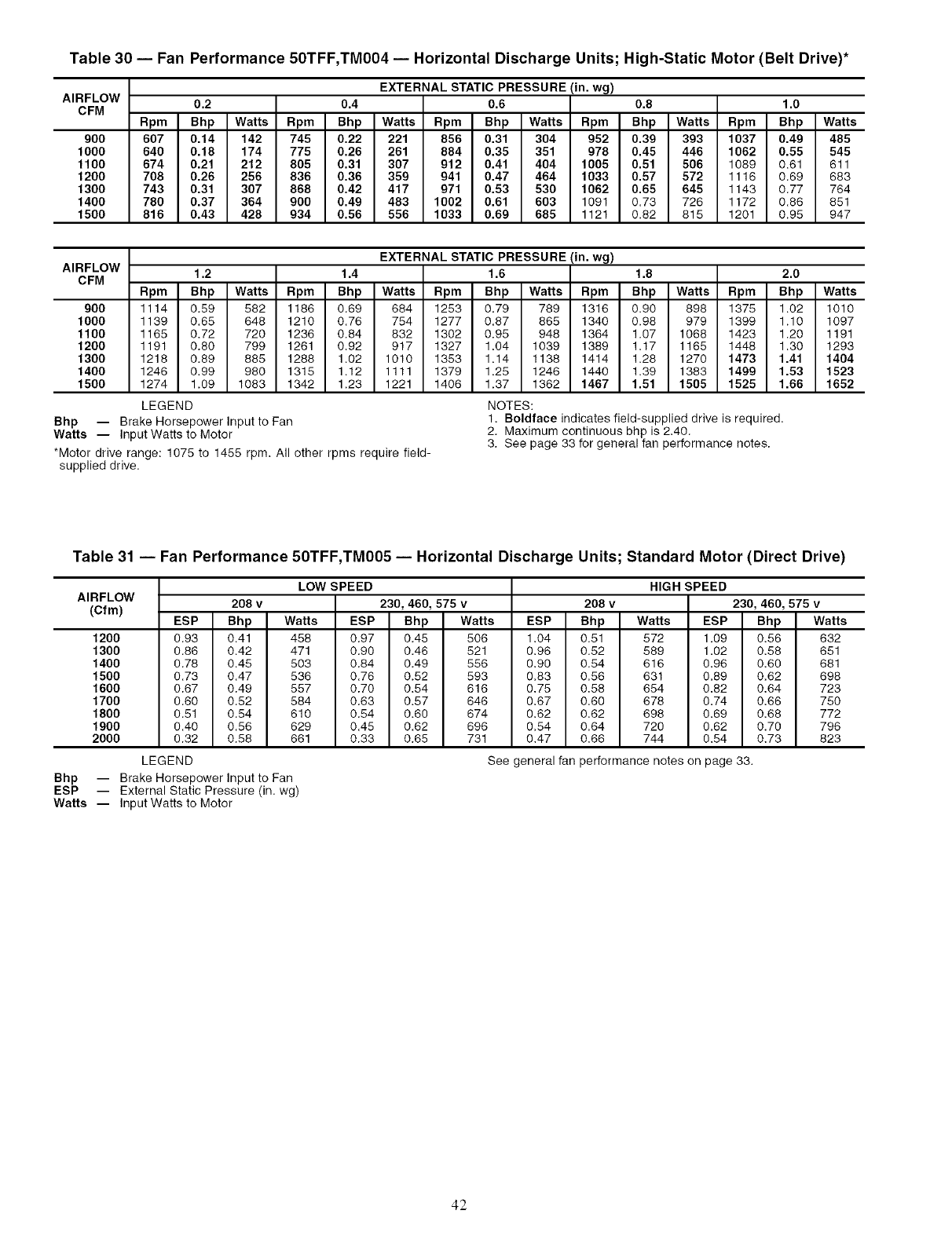
Table 30 -- Fan Performance 50TFF,TM004 -- Horizontal Discharge Units; High-Static Motor (Belt Drive)*
AIRFLOW
CFM
900
1000
1100
1200
1300
1400
1500
EXTERNAL STATIC PRESSURE (in. wg)
0.2 0.4 0.6 0.8 1.0
Rpm Bhp Watts Rpm Bhp Watts Rpm Bhp Watts Rpm Bhp Watts Rpm Bhp Watts
607 0.14 142 745 0.22 221 856 0.31 304 952 0.39 393 1037 0.49 485
640 0.18 174 775 0.26 261 884 0.35 351 978 0.45 446 1062 0.55 545
674 0.21 212 805 0.31 307 912 0.41 404 1005 0.51 506 1089 0.61 611
708 0.26 256 836 0.36 359 941 0.47 464 1033 0.57 572 1116 0.69 683
743 0.31 307 868 0.42 417 971 0.53 530 1062 0.65 645 1143 0.77 764
780 0.37 364 900 0.49 483 1002 0.61 603 1091 0.73 726 1172 0.88 851
816 0.43 428 934 0.56 556 1033 0.69 685 1121 0.82 815 1201 0.95 947
AIRFLOW
CFM
900
1000
1100
1200
1300
1400
1500
Bhp -- Brake Horsepower Input to Fan
Watts -- Input Watts to Motor
*Motor drive range: 1075 to 1455 rpm. All other rpms require field-
supplied drive.
EXTERNAL STATIC PRESSURE (in. wg)
1.2 1.4 1.6 1.8 2.0
Rpm Bhp Watts Rpm Bhp Watts Rpm Bhp Watts Rpm Bhp Watts Rpm Bhp Watts
1114 0.59 582 1186 0.69 684 1253 0.79 789 1316 0.90 898 1375 1.02 1010
1139 0.65 648 1210 0.76 754 1277 0.87 865 1340 0.98 979 1399 1.10 1097
1165 0.72 720 1236 0.84 832 1302 0.95 948 1364 1.07 1068 1423 1.20 1191
1191 0.80 799 1261 0.92 917 1327 1.04 1039 1389 1.17 1165 1448 1.30 1293
1218 0.89 885 1288 1.02 1010 1353 1.14 1138 1414 1.28 1270 1473 1.41 1404
1246 0.99 980 1315 1.12 1111 1379 1.25 1246 1440 1.39 1383 1499 1.53 1523
1274 1.09 1083 1342 1.23 1221 1406 1.37 1362 1467 1.51 1505 1525 1.66 1652
LEGEND NOTES:
1. Boldface indicates field-supplied drive is required,
2. Maximum continuous bhp is 2,40.
3. See page 33 for general fan performance notes.
Table 31 -- Fan Performance 50TFF,TM005 -- Horizontal Discharge Units; Standard Motor (Direct Drive)
AIRFLOW
(Cfm)
1200
1300
1400
1500
1600
1700
1800
1900
2000
LOW SPEED
208 v 230, 460, 575 v
ESP Bhp Watts ESP Bhp Watts
0.93 0.41
0.86 0.42
0.78 0.45
0.73 0.47
0.67 0.49
0.60 0.52
0.51 0.54
0.40 0.56
0.32 0.58
LEGEND
458 0.97 0.45 506
471 0.90 0.46 521
503 0.84 0.49 556
536 0.76 0.52 593
557 0.70 0.54 616
584 0.63 0.57 646
610 0.54 0.60 674
629 0.45 0.62 696
661 0.33 0.65 731
HIGH SPEED
208 v 230, 460, 575 v
ESP Bhp Watts ESP Bhp Watts
1.04 0.51 572 1.09 0.56 632
0.96 0.52 589 1.02 0.58 651
0.90 0.54 616 0.96 0.60 681
0.83 0.56 631 0.89 0.62 698
0,75 0.58 654 0.82 0.64 723
0.67 0.60 678 0,74 0.66 750
0.62 0.62 698 0.69 0.68 772
0.54 0.64 720 0.62 0.70 796
0.47 0.66 744 0.54 0.73 823
See general fan performance notes on page 33.
Bhp -- Brake Horsepower Input to Fan
ESP -- External Static Pressure (in. wg)
Watts -- Input Watts to Motor
42

Table 32 -- Fan Performance 50TFF005 -- Horizontal Discharge Units; Alternate Motor (Belt Drive)*
AIRFLOW
CFM
1200
1300
1400
1500
1600
1700
1800
1900
2000
EXTERNAL STATIC PRESSURE (in. wg)
0.2 0.4 0.6 0.8 1.0
Rpm Bhp Watts Rpm Bhp Watts Rpm Bhp Watts Rpm Bhp Watts Rpm Bhp Watts
643 0.23 233 762 0.35 344 860 0.46 459 944 0.58 579 1020 0.71 705
674 0.28 276 791 0.40 395 887 0.52 517 970 0.65 645 1045 0.78 777
706 0.33 324 820 0.45 451 914 0.59 582 997 0.72 717 1071 0.86 857
738 0.38 379 849 0.52 515 942 0.66 653 1024 0.80 796 1097 0.95 942
771 0.44 440 879 0.59 584 971 0.74 731 1051 0.89 881 1124 1.04 1035
804 0.51 507 910 0.66 661 1000 0.82 816 1079 0.98 974 1151 1.14 1136
837 0.59 582 941 0.75 745 1029 0.91 909 1107 1.08 1075 -- -- --
871 0.67 665 972 0.84 837 1059 1.02 1010 1136 1.19 1184 -- -- --
906 0.76 756 1004 0.94 938 1089 1.12 1119 ......
AIRFLOW
CFM
1200
1300
1400
1500
1600
1700
1800
1900
2000
LEGEND
Bhp -- Brake Horsepower Input to Fan
Watts -- Input Watts to Motor
*Motor drive range: 835 to 1185 rpm. All other rpms require field-
supplied drive.
EXTERNAL STATIC PRESSURE (in. wg)
1.2 1.4 1.6 1.8 2.0
Rpm Bhp Watts Rpm Bhp Watts Rpm Bhp Watts Rpm Bhp Watts Rpm Bhp
1089 0.84 835 1153 0.98 971 1212 1.12 1111 .....
1114 0.92 915 1177 1.06 1056 ........
1139 1.01 1000 1202 1.15 1149 ........
1164 1.10 1093 ...........
1190 1.20 1193 ...........
NOTES:
1. Boldface indicates field-supplied drive is required.
2. Maximum continuous bhp is 1.20.
3. See page 33 for general fan performance notes.
Watts
Table 33 -- Fan Performance 50TM005 -- Horizontal Discharge Units; Alternate Motor (Belt Drive)*
AIRFLOW
CFM
9O0
1000
1100
1200
1300
1400
1500
1600
1700
1800
1900
2000
EXTERNAL STATIC PRESSURE (in. wg)
0.2 0.4 0.6 0.8 1.0
Rpm Bhp Watts Rpm Bhp Watts Rpm Bhp Watts Rpm Bhp Watts Rpm Bhp Watts
554 0.14 134 681 0.22 222 783 0.32 316 870 0.42 416 947 0.53 523
583 0.16 163 707 0.26 257 808 0.36 358 894 0.47 465 971 0.58 578
612 0.20 195 735 0.30 298 834 0.41 406 919 0.52 519 995 0.64 638
643 0.23 233 762 0.35 344 860 0.46 459 944 0.58 579 1020 0.71 705
674 0.28 276 791 0.40 395 887 0.52 517 970 0.65 645 1045 0.78 777
706 0.33 324 820 0.45 451 914 0.59 582 997 0.72 717 1071 0.86 857
738 0.38 379 849 0.52 515 942 0.66 653 1024 0.80 796 1097 0.95 942
771 0.44 440 879 0.59 584 971 0.74 731 1051 0.89 881 1124 1.04 1035
804 0.51 507 910 0.66 661 1000 0.82 816 1079 0.98 974 1151 1.14 1136
837 0.59 582 941 0.75 745 1029 0.91 909 1107 1.08 1075 -- -- --
871 0.67 665 972 0.84 837 1059 1.02 1010 1136 1.19 1184 -- -- --
906 0.76 756 1004 0.94 938 1089 1.12 1119 1165 .....
AIRFLOW
CFM
900
1000
1100
1200
1300
1400
1500
1600
1700
1800
1900
2000
EXTERNAL STATIC PRESSURE (in. wg)
1.2 1.4 1.6 1.8 2.0
Rpm Bhp Watts Rpm Bhp Watts Rpm Bhp Watts Rpm Bhp Watts Rpm Bhp Watts
1017 0.64 635 1082 0.76 753 1143 0.88 876 1200 1.01 1004 1254 1.14 1136
1041 0.70 696 1105 0.82 820 1166 0.95 948 1223 1.09 1081 -- -- --
1065 0.77 763 1129 0.90 892 1189 1.03 1026 1245 1.17 1165 -- -- --
1089 0.84 835 1153 0.98 971 1212 1.12 1111 ......
1114 0.92 915 1177 1.06 1056 .........
1139 1.01 1000 1202 1.15 1149 .........
1164 1.10 1093 ............
1190 1.20 1193 ............
LEGEND
Bhp -- Brake Horsepower Input to Fan
Watts -- Input Watts to Motor
*Motor drive range: 770 to 1175 rpm. All other rpms require field-
supplied drive.
NOTES:
1. Boldface indicates field-supplied drive is required.
2. Maximum continuous bhp is 1.20.
3. See page 33 for general fan performance notes.
43
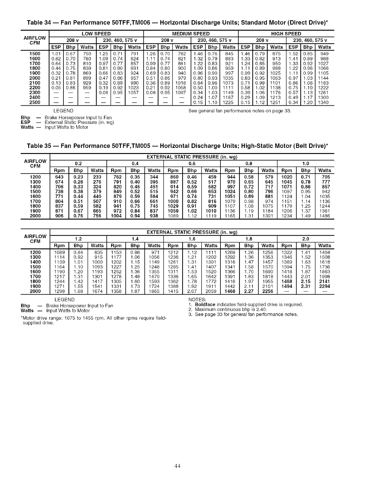
Table 34 -- Fan Performance 50TFF,TM006 -- Horizontal Discharge Units; Standard Motor (Direct Drive)*
AIRFLOW
CFM
15OO
1600
1700
1800
1900
2000
2100
2200
2300
2400
2500
LOW SPEED
208 v 230, 460, 575 v
ESP Bhp Watts ESP Bhp Watts
1.01 0.67 750 1.25 0.71 791
0.82 0.70 780 1.09 0.74 824
0.64 0.73 810 0.97 0.77 857
0.44 0.75 839 0.81 0.80 891
0.32 0.78 869 0.66 0.83 924
0.21 0.81 899 0.47 0.86 957
0.13 0.83 929 0.32 0.89 990
0.05 0.86 959 0.19 0.92 1023
0.08 0.96 1057
LEGEND
MEDIUM SPEED
208 v 230, 460, 575 v
ESP Bhp Watts ESP Bhp Watts
1.26 0.70 782 1.46 0.76 845
1.11 0.74 821 1.32 0.79 883
0.99 0.77 861 1.22 0.83 921
0.84 0.80 900 1.09 0.86 959
0.69 0.83 940 0.96 0.90 997
0.51 0.86 979 0.80 0.93 1035
0.36 0.89 1018 0.64 0.96 1073
0.21 0.92 1058 0.50 1.00 1111
0.08 0.95 1097 0.34 1.03 1149
-- 0.24 1.07 1187
-- 0.15 1.10 1225
HIGH SPEED
208 v 230, 460, 575 v
ESP Bhp Watts ESP Bhp Watts
1.46 0.79 875 1.52 0.85 949
1.33 0.82 913 1.41 0.89 988
1.24 0.85 950 1.33 0.92 1027
1.11 0.89 988 1.22 0.96 1066
0.99 0.92 1025 1.11 0.99 1105
0.83 0.95 1063 0.97 1.03 1144
0.71 0.99 1101 0.86 1.06 1183
0.58 1.02 1138 0.76 1.10 1222
0.39 1.06 1176 0.57 1.13 1261
0.29 1.09 1213 0.49 1.17 1300
0.16 1.12 1251 0.34 1.20 1340
See general fan performance notes on page 33.
Bhp -- Brake Horsepower Input to Fan
ESP -- External Static Pressure (in. wg)
Watts -- Input Watts to Motor
Table 35 -- Fan Performance 50TFF,TM005 -- Horizontal Discharge Units; High-Static Motor (Belt Drive)*
AIRFLOW
CFM
1200
1300
1400
1500
1600
1700
1800
1900
2000
EXTERNAL STATIC PRESSURE (in. wg)
0.2 0.4 0.6 0.8 1.0
Rpm Bhp Watts Rpm Bhp Watts Rpm Bhp Watts Rpm Bhp Watts Rpm Bhp Watts
643 0.23 233 762 0.35 344 860 0.46 459 944 0.58 579 1020 0.71 705
674 0.28 276 791 0.40 395 887 0.52 517 970 0.65 645 1045 0.78 777
706 0.33 324 820 0.45 451 914 0.59 582 997 0.72 717 1071 0.86 857
738 0.38 379 849 0.52 515 942 0.66 653 1024 0.80 796 1097 0.95 942
771 0.44 440 879 0.59 584 971 0.74 731 1051 0.89 881 1124 1.04 1035
804 0.51 507 910 0.66 661 1000 0.82 816 1079 0.98 974 1151 1.14 1136
837 0.59 582 941 0.75 745 1029 0.91 909 1107 1.08 1075 1176 1.25 1244
871 0.67 665 972 0.84 837 1059 1.02 1010 1138 1.19 1164 1206 1.37 1361
906 0.76 756 1004 0.94 938 1089 1.12 1119 1165 1.31 1301 1234 1.49 1488
AIRFLOW
CFM
1200
1300
1400
1500
1600
1700
1800
1900
2000
Bhp -- Brake Horsepower Input to Fan
Watts -- Input Watts to Motor
*Motor drive range: 1075 to 1455 rpm. All other rpms require field-
supplied drive.
EXTERNAL STATIC PRESSURE (in. wg)
1.2 1.4 1.6 1.8 2.0
Rpm Bhp Watts Rpm Bhp Watts Rpm Bhp Watts Rpm Bhp Watts Rpm Bhp Watts
1089 0.84 835 1153 0.98 971 1212 1.12 1111 1269 1.26 1256 1322 1.41 1404
1114 0.92 915 1177 1.06 1056 1236 1.21 1202 1292 1.36 1353 1346 1.82 1508
1139 1.01 1000 1202 1.15 1149 1261 1.31 1301 1316 1.47 1457 1369 1.63 1618
1164 1.10 1093 1227 1.25 1248 1285 1.41 1407 1341 1.88 1570 1394 1.75 1736
1190 1.20 1193 1252 1.36 1355 1311 1.83 1520 1366 1.70 1690 1418 1.87 1863
1217 1.31 1301 1278 1.48 1470 1336 1.65 1642 1391 1.83 1818 1443 2.01 1998
1244 1.42 1417 1305 1.60 1593 1362 1.78 1772 1416 1.97 1955 1468 2,15 2141
1271 1.55 1541 1331 1.73 1724 1388 1.92 1911 1442 2.11 2101 1494 2.31 2294
1298 1.68 1674 1358 1.87 1865 1415 2.07 2059 1468 2.27 2256 -- -- --
LEGEND NOTES:
1. Boldface indicates field-supplied drive is required,
2. Maximum continuous bhp is 2,40.
3. See page 33 for general fan performance notes.
44
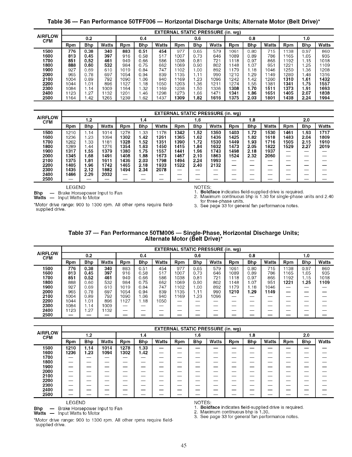
Table 36 -- Fan Performance 50TFF006 -- Horizontal Discharge Units; Alternate Motor (Belt Drive)*
AIRFLOW
CFM
1500
1600
1700
1800
1900
2000
2100
2200
2300
2400
2500
EXTERNAL STATIC PRESSURE (in. wg)
0.2 0.4 0.6 0.8 1.0
Rpm Bhp Watts Rpm Bhp Watts Rpm Bhp Watts Rpm Bhp Watts Rpm Bhp Watts
776 0.38 340 883 0.51 454 977 0.65 579 1061 0.80 715 1138 0.97 860
813 0.45 397 916 0.58 517 1007 0.73 646 1089 0.89 786 1165 1.05 935
851 0.52 461 949 0.66 586 1038 0.81 721 1118 0.97 865 1192 1.15 1018
888 0.60 532 984 0.75 662 1069 0.90 802 1148 1.07 951 1221 1.25 1109
927 0.69 610 1019 0.84 747 1102 1.00 892 1179 1.18 1046 1250 1.36 1208
965 0.78 697 1054 0.94 839 1135 1.11 990 1210 1.29 1149 1280 1.48 1316
1004 0.89 792 1090 1.06 940 1169 1.23 1096 1242 1.42 1260 1310 1.61 1432
1044 1.01 896 1127 1.18 1050 1203 1.36 1211 1274 1.55 1381 1341 1.75 1557
1084 1.14 1009 1164 1.32 1169 1238 1.50 1336 1308 1.70 1511 1373 1.91 1693
1123 1.27 1132 1201 1.46 1298 1273 1.66 1471 1341 1.86 1651 1405 2.07 1838
1164 1.42 1265 1239 1.62 1437 1309 1.82 1616 1375 2.03 1801 1438 2.24 1994
AIRFLOW
CFM
1500
1600
1700
1800
1900
2000
2100
2200
2300
2400
2500
LEGEND
Bhp -- Brake Horsepower Input to Fan
Watts -- Input Watts to Motor
*Motor drive range: 900 to 1300 rpm. All other rpms require field-
supplied drive.
EXTERNAL STATIC PRESSURE (in. wg)
1.2 1.4 1.6 1.8 2.0
Rpm Bhp Watts Rpm Bhp Watts Rpm Bhp Watts Rpm Bhp Watts Rpm Bhp Watts
1210 1.14 1014 1278 1.33 1178 1342 1.52 1350 1403 1.72 1530 1461 1.93 1717
1236 1.23 1094 1302 1.42 1261 1365 1.62 1436 1425 1.82 1618 1483 2.04 1809
1262 1.33 1181 1328 1.52 1351 1390 1.72 1530 1449 1.93 1716 1505 2.15 1910
1289 1.44 1276 1354 1.63 1450 1415 1.84 1632 1473 2.05 1822 1529 2.27 2019
1317 1.55 1379 1380 1.75 1557 1441 1.96 1743 1498 2.18 1937 -- -- --
1345 1.68 1491 1408 1.88 1673 1467 2.10 1863 1524 2.32 2060 -- -- --
1375 1.81 1611 1436 2.03 1798 1494 2.24 1993 ......
1405 1.96 1742 1465 2.18 1933 1522 2.40 2132 ......
1435 2.12 1882 1494 2.34 2078 .........
1466 2.29 2032 ............
NOTES:
1. Boldface indicates field-supplied drive is required.
2. Maximum continuous bhp is 1.30 for single-phase units and 2.40
for three-phase units.
3. See page 33 for general fan performance notes.
AIRFLOW
CFM
1500
1600
1700
1800
1900
2000
2100
2200
2300
2400
2500
Table 37 -- Fan Performance 50TM006 -- Single-Phase, Horizontal Discharge Units;
Alternate Motor (Belt Drive)*
EXTERNAL STATIC PRESSURE (in. wg)
0.2 0.4 0.6 0.8 1.0
Rpm Bhp Watts Rpm Bhp Watts Rpm Bhp Watts Rpm Bhp Watts Rpm Bhp Watts
776 0.38 340 883 0.51 454 977 0.65 579 1061 0.80 715 1138 0.97 860
813 0.45 397 916 0.58 517 1007 0.73 646 1089 0.89 786 1165 1.05 935
851 0.52 461 949 0.66 586 1038 0.81 721 1118 0.97 865 1192 1.15 1018
888 0.60 532 984 0.75 662 1069 0.90 802 1148 1.07 951 1221 1.25 1109
927 0.69 610 1019 0.84 747 1102 1.00 892 1179 1.18 1046 -- -- --
965 0.78 697 1054 0.94 839 1135 1.11 990 1210 1.29 1149 -- -- --
1004 0.89 792 1090 1.06 940 1169 1.23 1096 ......
1044 1.01 896 1127 1.18 1050 .........
1084 1.14 1009 ............
1123 1.27 1132 ............
AIRFLOW
CFM
1500
1600
1700
1800
1900
2000
2100
2200
2300
2400
2500
EXTERNAL STATIC PRESSURE (in. wg)
1.2 1.4 1.6 1.8 2.0
Rpm Bhp Watts Rpm Bhp Watts Rpm Bhp Watts Rpm Bhp Watts Rpm Bhp Watts
1210 1.14 1014 1278 1.33 -- -- --
1236 1.23 1094 1302 1.42 -- -- --
m
m
m
m
m
m
m
m
m
m
m
m
m
m
m
m
m
m
m
m
m
m
m
m
m
m
m
m
m
m
m
m
m
m
m
m
m m
m m
m m
m m
m m
m m
m m
m m
m m
m
m
m
m
m
m
m
m
m
LEGEND
Bhp -- Brake Horsepower Input to Fan
Watts -- Input Watts to Motor
*Motor drive range: 900 to 1300 rpm. All other rpms require field-
supplied drive.
NOTES:
1. Boldface indicates field-supplied drive is required.
2. Maximum continuous bhp is 1.30.
3. See page 33 for general fan performance notes.
45
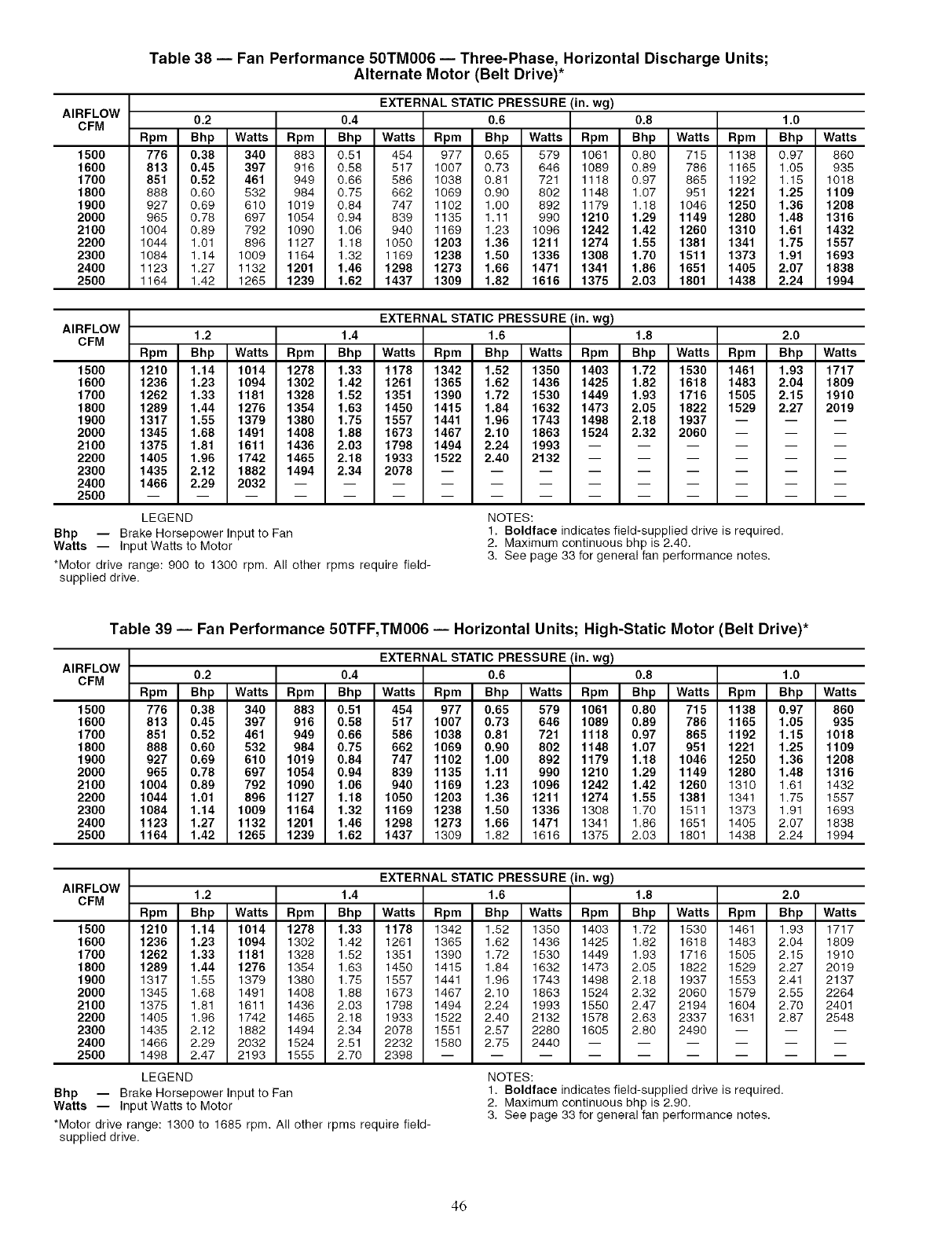
AIRFLOW
CFM
1500
1600
1700
1800
1900
2000
2100
2200
2300
2400
2500
Table 38 -- Fan Performance 50TM006 -- Three-Phase, Horizontal Discharge Units;
Alternate Motor (Belt Drive)*
EXTERNAL STATIC PRESSURE (in. wg)
0.2 0.4 0.6 0.8 1.0
Rpm Bhp Watts Rpm Bhp Watts Rpm Bhp Watts Rpm Bhp Watts Rpm Bhp Watts
776 0.38 340 883 0.51 454 977 0.65 579 1061 0.80 715 1138 0.97 860
813 0.45 397 916 0.58 517 1007 0.73 646 1089 0.89 786 1165 1.05 935
851 0.52 461 949 0.66 586 1038 0.81 721 1118 0.97 865 1192 1.15 1018
888 0.60 532 984 0.75 662 1069 0.90 802 1148 1.07 951 1221 1.25 1109
927 0.69 610 1019 0.84 747 1102 1.00 892 1179 1.18 1046 1250 1.36 1208
965 0.78 697 1054 0.94 839 1135 1.11 990 1210 1.29 1149 1280 1.48 1316
1004 0.89 792 1090 1.06 940 1169 1.23 1096 1242 1.42 1260 1310 1.61 1432
1044 1.01 896 1127 1.18 1050 1203 1.36 1211 1274 1.55 1381 1341 1.75 1557
1084 1.14 1009 1164 1.32 1169 1238 1.50 1336 1308 1.70 1511 1373 1.91 1693
1123 1.27 1132 1201 1.46 1298 1273 1.66 1471 1341 1.86 1651 1405 2.07 1838
1164 1.42 1265 1239 1.62 1437 1309 1.82 1616 1375 2.03 1801 1438 2.24 1994
AIRFLOW
CFM
1500
1600
1700
1800
1900
2000
2100
2200
2300
2400
2500
LEGEND
Bhp -- Brake Horsepower Input to Fan
Watts -- Input Watts to Motor
*Motor drive range: 900 to 1300 rpm. All other rpms require field-
supplied drive.
EXTERNAL STATIC PRESSURE (in. wg)
1.2 1.4 1.6 1.8 2.0
Rpm Bhp Watts Rpm Bhp Watts Rpm Bhp Watts Rpm Bhp Watts Rpm Bhp Watts
1210 1.14 1014 1278 1.33 1178 1342 1.52 1350 1403 1.72 1530 1461 1.93 1717
1236 1.23 1094 1302 1.42 1261 1365 1.62 1436 1425 1.82 1618 1483 2.04 1809
1262 1.33 1181 1328 1.52 1351 1390 1.72 1530 1449 1.93 1716 1505 2.15 1910
1289 1.44 1276 1354 1.63 1450 1415 1.84 1632 1473 2.05 1822 1529 2.27 2019
1317 1.55 1379 1380 1.75 1557 1441 1.96 1743 1498 2.18 1937 -- -- --
1345 1.68 1491 1408 1.88 1673 1467 2.10 1863 1524 2.32 2060 -- -- --
1375 1.81 1611 1436 2.03 1798 1494 2.24 1993 ......
1405 1.96 1742 1465 2.18 1933 1522 2.40 2132 ......
1435 2.12 1882 1494 2.34 2078 .........
1466 2.29 2032 ............
NOTES:
1. Boldface indicates field-supplied drive is required.
2. Maximum continuous bhp is 2.40.
3. See page 33 for general fan performance notes.
Table 39 -- Fan Performance 50TFF,TM006 -- Horizontal Units; High-Static Motor (Belt Drive)*
AIRFLOW
CFM
1500
1600
1700
1800
1900
2000
2100
2200
2300
2400
2500
EXTERNAL STATIC PRESSURE (in. wg)
0.2 0.4 0.6 0.8 1.0
Rpm Bhp Watts Rpm Bhp Watts Rpm Bhp Watts Rpm Bhp Watts Rpm Bhp Watts
776 0.38 340 883 0.51 454 977 0.65 579 1061 0.80 715 1138 0.97 860
813 0.45 397 916 0.58 517 1007 0.73 646 1089 0.89 786 1165 1.05 935
851 0.52 461 949 0.66 586 1038 0.81 721 1118 0.97 865 1192 1.15 1018
888 0.60 532 984 0.75 662 1069 0.90 802 1148 1.07 951 1221 1.25 1109
927 0.69 610 1019 0.84 747 1102 1.00 892 1179 1.18 1046 1250 1.36 1208
965 0.78 697 1054 0.94 839 1135 1.11 990 1210 1.29 1149 1280 1.48 1316
1004 0.89 792 1090 1.06 940 1169 1.23 1096 1242 1.42 1260 1310 1.61 1432
1044 1.01 896 1127 1.18 1050 1203 1.36 1211 1274 1.55 1381 1341 1.75 1557
1084 1.14 1009 1164 1.32 1169 1238 1.50 1336 1308 1.70 1511 1373 1.91 1693
1123 1.27 1132 1201 1.46 1298 1273 1.66 1471 1341 1.86 1651 1405 2.07 1838
1164 1.42 1265 1239 1.62 1437 1309 1.82 1616 1375 2.03 1801 1438 2.24 1994
AIRFLOW
CFM
1500
1600
1700
1800
1900
2000
2100
2200
2300
2400
2500
Bhp -- Brake Horsepower Input to Fan
Watts -- Input Watts to Motor
*Motor drive range: 1300 to 1685 rpm. All other rpms require field-
supplied drive.
EXTERNAL STATIC PRESSURE (in. wg)
1.2 1.4 1.6 1.8 2.0
Rpm Bhp Watts Rpm Bhp Watts Rpm Bhp Watts Rpm Bhp Watts Rpm Bhp Watts
1210 1.14 1014 1278 1.33 1178 1342 1.52 1350 1403 1.72 1530 1461 1.93 1717
1236 1.23 1094 1302 1.42 1261 1365 1.62 1436 1425 1.82 1618 1483 2.04 1809
1262 1.33 1181 1328 1.52 1351 1390 1.72 1530 1449 1.93 1716 1505 2.15 1910
1289 1.44 1276 1354 1.63 1450 1415 1.84 1632 1473 2.05 1822 1529 2.27 2019
1317 1.55 1379 1380 1.75 1557 1441 1.96 1743 1498 2.18 1937 1553 2.41 2137
1345 1.68 1491 1408 1.88 1673 1467 2.10 1863 1524 2.32 2060 1579 2.55 2264
1375 1.81 1611 1436 2.03 1798 1494 2.24 1993 1550 2.47 2194 1604 2.70 2401
1405 1.96 1742 1465 2.18 1933 1522 2.40 2132 1578 2.63 2337 1631 2.87 2548
1435 2.12 1882 1494 2.34 2078 1551 2.57 2280 1605 2.80 2490 -- -- --
1466 2.29 2032 1524 2.51 2232 1580 2.75 2440 ......
1498 2.47 2193 1555 2.70 2398 .........
LEGEND NOTES:
1. Boldface indicates field-supplied drive is required,
2. Maximum continuous bhp is 2,90.
3. See page 33 for general fan performance notes.
46
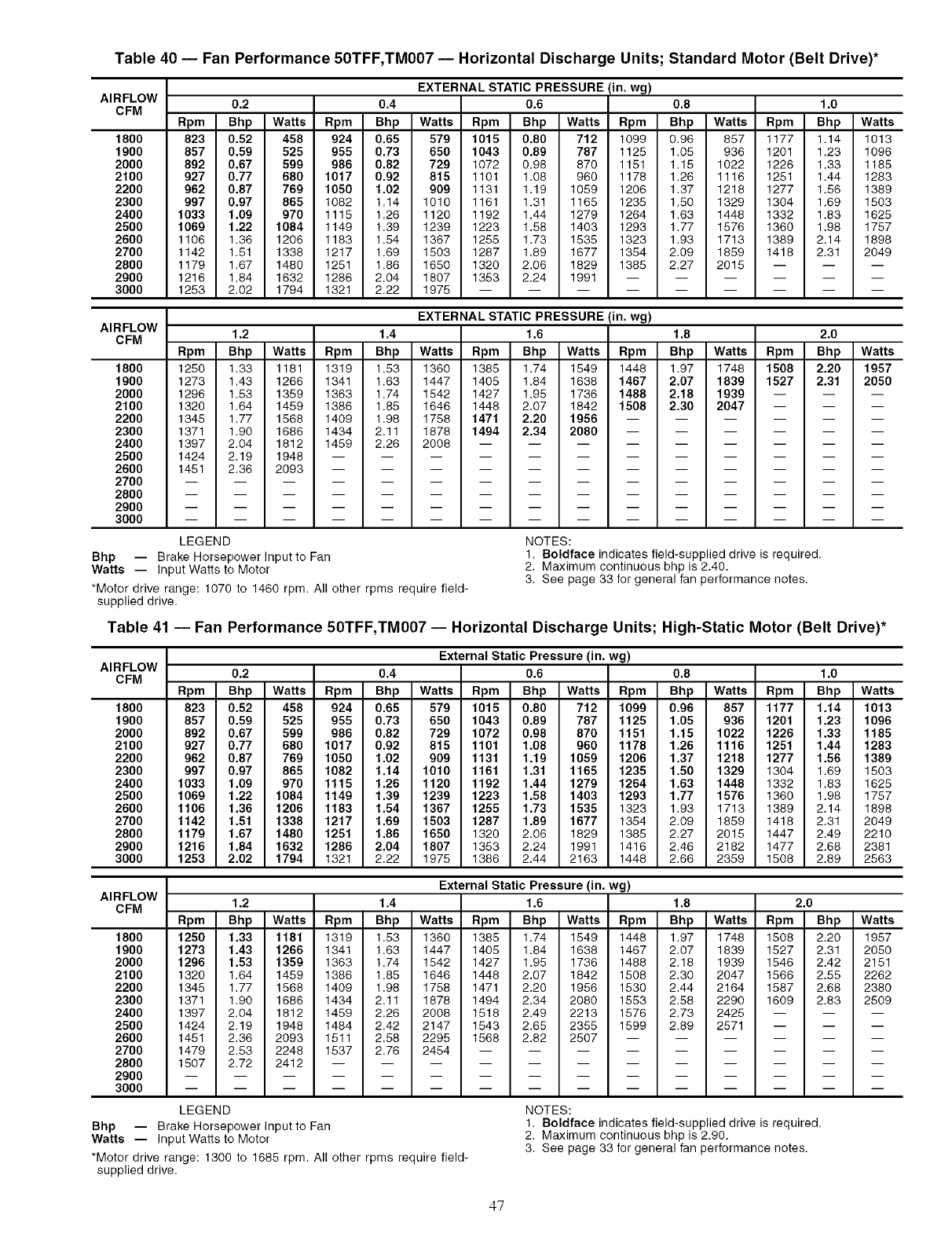
Table 40 -- Fan Performance 50TFF,TM007 -- Horizontal Discharge Units; Standard Motor (Belt Drive)*
AIRFLOW
CFM
1800
1900
2000
2100
2200
2300
2400
2500
2600
2700
2800
2900
3000
EXTERNAL STATIC PRESSURE (in. wg)
0.2 0.4 0.6 0.8 1.0
Rpm Bhp Watts Rpm Bhp Watts Rpm Bhp Watts Rpm Bhp Watts Rpm Bhp Watts
823 0.52 458 924 0.65 579 1015 0.80 712 1099 0.96 857 1177 1.14 1013
857 0.59 525 955 0.73 650 1043 0.89 787 1125 1.05 936 1201 1.23 1096
892 0.67 599 986 0.82 729 1072 0.98 870 1151 1.15 1022 1226 1.33 1185
927 0.77 680 1017 0.92 815 1101 1.08 960 1178 1.26 1116 1251 1.44 1283
962 0.87 769 1050 1.02 909 1131 1.19 1059 1206 1.37 1218 1277 1.56 1389
997 0.97 865 1082 1.14 1010 1161 1.31 1165 1235 1.50 1329 1304 1.69 1503
1033 1.09 970 1115 1.26 1120 1192 1.44 1279 1264 1.63 1448 1332 1.83 1625
1069 1.22 1084 1149 1.39 1239 1223 1.58 1403 1293 1.77 1576 1360 1.98 1757
1106 1.36 1206 1183 1.54 1367 1255 1.73 1535 1323 1.93 1713 1389 2.14 1898
1142 1.51 1338 1217 1.69 1503 1287 1.89 1677 1354 2.09 1859 1418 2.31 2049
1179 1.67 1480 1251 1.86 1650 1320 2.06 1829 1385 2.27 2015 -- -- --
1216 1.84 1632 1286 2.04 1807 1353 2.24 1991 ......
1253 2.02 1794 1321 2.22 1975 .........
AIRFLOW
CFM
1800
1900
2000
2100
2200
2300
2400
2500
2600
2700
2800
2900
3000
EXTERNAL STATIC PRESSURE (in. wg)
1.2 1.4 1.6 1.8 2.0
Rpm Bhp Watts Rpm Bhp Watts Rpm Bhp Watts Rpm Bhp Watts Rpm Bhp Watts
1250 1.33 1181 1319 1.53 1360 1385 1.74 1549 1448 1.97 1748 1508 2.20 1957
1273 1.43 1266 1341 1.63 1447 1405 1.84 1638 1467 2.07 1839 1527 2.31 2050
1296 1.53 1359 1363 1.74 1542 1427 1.95 1736 1488 2.18 1939 -- -- --
1320 1.64 1459 1386 1.85 1646 1448 2.07 1842 1508 2.30 2047 -- -- --
1345 1.77 1568 1409 1.98 1758 1471 2.20 1956 ......
1371 1.90 1686 1434 2.11 1878 1494 2.34 2080 ......
1397 2.04 1812 1459 2.26 2008 .........
1424 2.19 1948 ............
1451 2.36 2093 ............
LEGEND
Bhp -- Brake Horsepower Input to Fan
Watts -- Input Watts to Motor
*Motor drive range: 1070 to 1460 rpm. All other rpms require field-
supplied drive.
NOTES:
1. Boldface indicates field-supplied drive is required.
2. Maximum continuous bhp is 2.40.
3. See page 33 for general fan performance notes.
Table 41 -- Fan Performance 50TFF,TM007 -- Horizontal Discharge Units; High-Static Motor (Belt Drive)*
AIRFLOW
CFM
1800
1900
2000
2100
2200
2300
2400
2500
2600
2700
2800
2900
3000
External Static Pressure (in. wg)
0.2 0.4 0.6 0.8 1.0
Rpm Bhp Watts Rpm Bhp Watts Rpm Bhp Watts Rpm Bhp Watts Rpm Bhp Watts
823 0.52 458 924 0.65 579 1015 0.80 712 1099 0.96 857 1177 1.14 1013
857 0.59 525 955 0.73 650 1043 0.89 787 1125 1.05 936 1201 1.23 1096
892 0.67 599 986 0.82 729 1072 0.98 870 1151 1.15 1022 1226 1.33 1185
927 0.77 680 1017 0.92 815 1101 1.08 960 1178 1.26 1116 1251 1.44 1283
962 0.87 769 1050 1.02 909 1131 1.19 1059 1206 1.37 1218 1277 1.56 1389
997 0.97 865 1082 1.14 1010 1161 1.31 1165 1235 1.50 1329 1304 1.69 1503
1033 1.09 970 1115 1.26 1120 1192 1.44 1279 1264 1.63 1448 1332 1.83 1625
1069 1.22 1084 1149 1.39 1239 1223 1.58 1403 1293 1.77 1576 1360 1.98 1757
1106 1.36 1206 1183 1.54 1367 1255 1.73 1535 1323 1.93 1713 1389 2.14 1898
1142 1.51 1338 1217 1.69 1503 1287 1.89 1677 1354 2.09 1859 1418 2.31 2049
1179 1.67 1480 1251 1.86 1650 1320 2.06 1829 1385 2.27 2015 1447 2.49 2210
1216 1.84 1632 1286 2.04 1807 1353 2.24 1991 1416 2.46 2182 1477 2.68 2381
1253 2.02 1794 1321 2.22 1975 1386 2.44 2163 1448 2.66 2359 1508 2.89 2563
AIRFLOW
CFM
1800
1900
2000
2100
2200
2300
2400
2500
2600
2700
2800
2900
3000
External Static Pressure (in. wg)
1.2 1.4 1.6 1.8 2.0
Rpm Bhp Watts Rpm Bhp Watts Rpm Bhp Watts Rpm Bhp Watts Rpm Bhp Watts
1250 1.33 1181 1319 1.53 1360 1385 1.74 1549 1446 1.97 1748 1508 2.20 1957
1273 1.43 1266 1341 1.63 1447 1405 1.84 1638 1467 2.07 1839 1527 2.31 2050
1296 1.53 1359 1363 1.74 1542 1427 1.95 1736 1488 2.18 1939 1546 2.42 2151
1320 1.64 1459 1386 1.85 1646 1448 2.07 1842 1508 2.30 2047 1566 2.55 2262
1345 1.77 1568 1409 1.98 1758 1471 2.20 1956 1530 2.44 2164 1587 2.68 2380
1371 1.90 1686 1434 2.11 1878 1494 2.34 2080 1553 2.58 2290 1609 2.83 2509
1397 2.04 1812 1459 2.26 2008 1518 2.49 2213 1576 2.73 2425 -- -- --
1424 2.19 1948 1484 2.42 2147 1543 2.65 2355 1599 2.89 2571 -- -- --
1451 2.36 2093 1511 2.58 2295 1568 2.82 2507 ......
1479 2.53 2248 1537 2.76 2454 .........
1507 2.72 2412 ............
LEGEND
Bhp -- Brake Horsepower Input to Fan
Watts -- Input Watts to Motor
*Motor drive range: 1300 to 1685 rpm. All other rpms require field-
supplied drive.
NOTES:
1. Boldface indicates field-supplied drive is required.
2. Maximum continuous bhp is 2.90.
3. See page 33 for general fan performance notes.
47
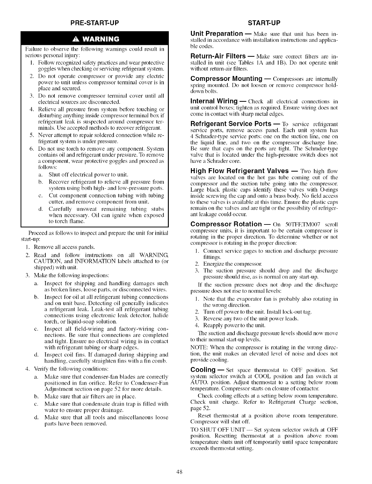
PRE-START-UP
F;filure to observe the following warnings could result in
serious personal injuu:
1. Follow recognized safety practices and wear protective
goggles when checking or servicing refrigerant system.
2. Do not operate compressor or provide any electric
power to unit unless compressor terminal cover is in
place and secured.
3. Do not remove compressor terminal cover until all
electrical sources are disconnected.
4. Relieve all pressure from system before touching or
disturbing anything inside compressor termimd box if
refiigerant leak is suspected around compressor ter-
minals. Use accepted methods to recover refiigerant.
5. Never attempt to repair soldered connection while re-
fiigerant system is under pressure.
6. Do not use torch to remove any component. System
contains oil and refiigerant under pressure. To remove
a component, wear protective goggles and proceed as
follows:
a. Shut off electrical power to unit.
b. Recover refiigerant to relieve all pressure from
system using both high- and low-pressure ports.
c. Cut component connection tubing with tubing
cutter, and remove component from unit.
d. Carefully unsweat remaining tubing stubs
when necessary. Oil can ignite when exposed
to torch flame.
Proceed as follows to inspect and prepale the unit for initkd
st_ut-up:
1. Remove all access panels.
2. Read and follow instructions on _dl WARNING.
CAUTION, and INFORMATION labels attached to (or
shipped) with unit.
3. Make the following inspections:
a. Inspect for shipping and handling damages such
as broken lines, loose parts, or disconnected wires.
b. Inspect for oil at all refrigerant tubing connections
and on unit base. Detecting oil generally indicates
a refrigerant leak. Leak-test all refrigerant tubing
connections using electronic leak detector, halide
torch, or liquid-soap solution.
c. Inspect all field-wiring and factory-wiring con-
nections. Be sure that connections are completed
and tight. Ensure no electrical wiring is in contact
with refrigerant tubing or sharp edges.
d. Inspect coil fins. If damaged during shipping and
handling, carefully straighten fins with a fin comb.
4. Verify the following conditions:
a. Make sure that condenser-fan blades are correctly
positioned in fan orifice. Refer to Condenser-Fan
Adjustment section on page 52 for more details.
b. Make sure that air filters are in place.
c. Make sure that condensate drain trap is filled with
water to ensure proper drainage.
d. Make sure that all tools and miscellaneous loose
parts have been removed.
START-UP
Unit Preparation- Make sure that unit has been in-
stalled in accordance with inst;_llation instructions and applica-
ble codes.
Return-Air Filters- Make sure correct filters ale in-
stalled in unit (see Tables IA and IB). Do not operate unit
without return-air filters.
Compressor Mounting- Compressors are internally
spring mounted. Do not loosen or remove compressor hold-
down bolts.
Internal Wiring- Check all electric_d connections in
unit control boxes; tighten as requiled. Ensure wiring does not
come in contact with sharp metal edges.
Refrigerant Service Ports -- To service refrigerant
service ports, remove access panel. Each unit system has
4 Schrader-type service ports: one on the suction line, one on
the liquid line, and two on the compressor discharge line.
Be sure that caps on the ports are tight. The Schmder-type
valve that is located under the high-pressure switch does not
have a Schrader core.
High Flow Refrigerant Valves -- Two high flow
valves are located on the hot gas tube coming out of the
compressor and the suction tube going into the compressol:
L;uge black plastic caps identify these valves with O-rings
inside screwing the cap and onto a brass body. No field access
to these wdves is available at this time. Ensure the plastic caps
remain on the valves and are tight or the possibility of refriger-
ant leakage could occm:
Compressor Rotation-- On 50TFF,TM007 scroll
compressor units, it is important to be certain compressor is
rotating in the proper direction. To determine whether or not
compressor is rotating in the proper direction:
1. Connect service gages to suction and discharge pressure
fittings.
2. Energize the compressol:
3. The suction pressure should diop and the discharge
pressure should rise, as is normal on any start-up.
If the suction pressure does not diop and the discharge
pressure does not rise to norlnal levels:
1. Note that the evaporator fan is probably _dso rotating in
the wrong direction.
2. Turn off power to the unit. Install lock-out tag.
3. Reverse any two of the unit power leads.
4. Reapply power to the unit.
The suction and discharge pressme levels should now move
to their normal start-up levels.
NOTE: When the compressor is rotating in the wrong direc-
tion, the unit makes an elevated level of noise and does not
provide cooling.
Cooling- Set space therlnostat to OFF position. Set
system selector switch at COOL position and fan switch at
AUTO. position. Adjust thermostat to a setting below room
temperature. Complessor st;uts on closure of contactoc
Check cooling effects at a setting below room temperature.
Check unit charge. Refer to Refrigerant Charge section,
page 52.
Reset thermostat at a position above room temperature.
Compressor will shut off.
TO SHUT OFF UNIT -- Set system selector switch at OFF
position. Resetting thermostat at a position above room
temperature shuts unit off tempor_uily until space temperature
exceeds thermostat setting.
48
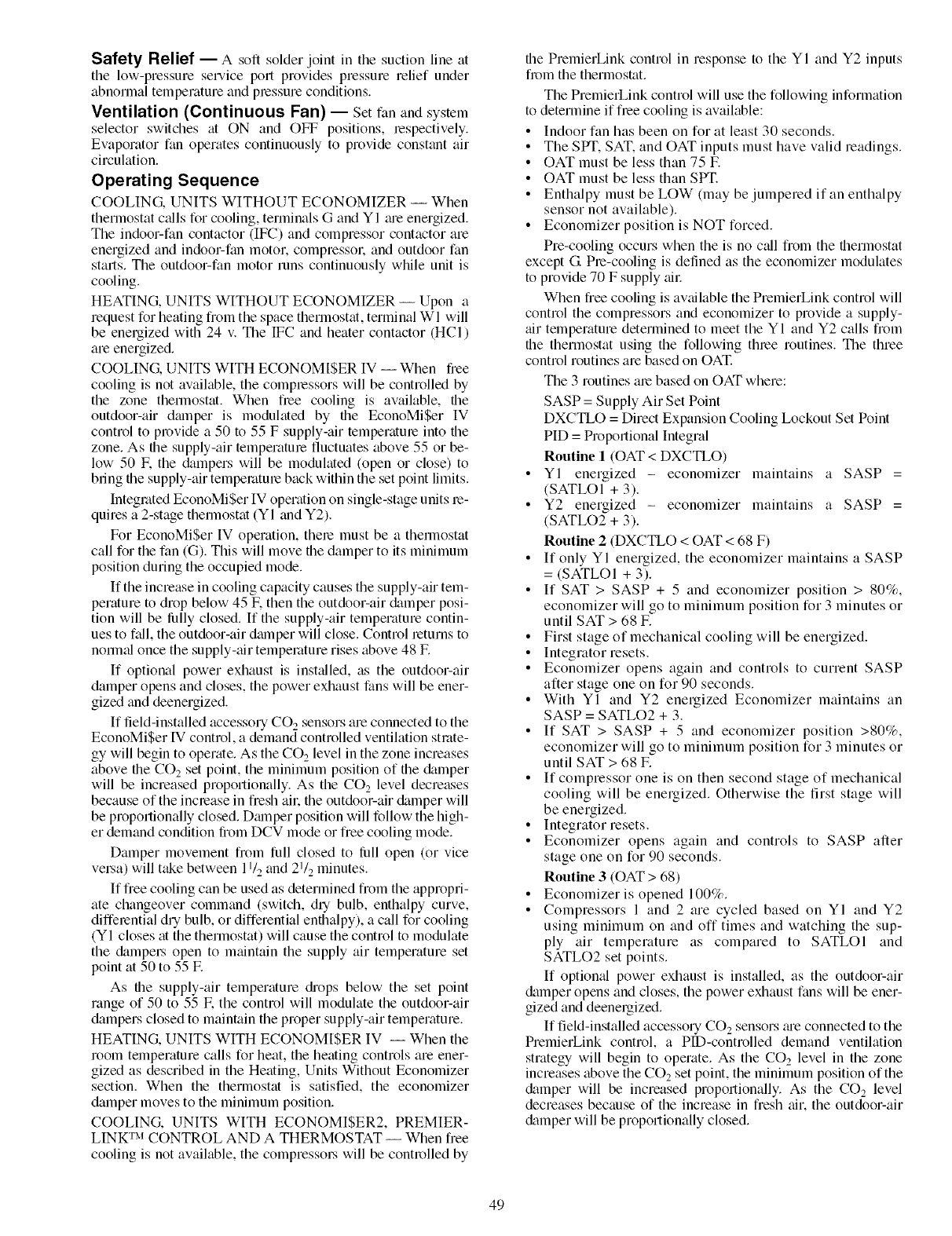
Safety Relief- A soft solder joint in tile suction line at
the low-pressure sel-vice port provides pressure relief under
abnormal temperature and pressure conditions.
Ventilation (Continuous Fan) -- Set fan and systeln
selector switches at ON and OFT positions, respectively.
Evaporator fan operates continuously to provide constant air
circulation.
Operating Sequence
COOLING. UNITS WITHOUT ECONOMIZER -- When
thermostat calls for cooling, terminals G and YI me energized.
The indoor-fan contactor (IFC) and compressor contactor are
energized and indoor-fan motor, compressol: and outdoor fan
starts. The outdoor-fan motor runs continuously while unit is
cooling.
HEATING, UNITS WITHOUT ECONOMIZER -- Upon a
request for heating from the space therlnostat, terminal WI will
be energized with 24 v. The IFC and heater contactor (HCI)
are energized.
COOLING, UNITS WITH ECONOMISER IV -- When free
cooling is not available, the complessors will be controlled by
the zone thermostat. When flee cooling is available, the
outdoor-air dmnper is modulated by the EconoMi$er IV
control to provide a 50 to 55 F supply-air temperatme into the
zone. As the supply-air temperatme fluctuates above 55 or be-
low 50 E the &_mpers will be modulated (open or close) to
bring the supply-air tempemtme back within the set point limits.
Integrated EconoMi$er IV operation on single-stage units re-
quires a 2-stage thennostat (YI and Y2).
For EconoMi$er IV operation, there must be a therlnostat
call for the fan (G). This will move the damper to its minimum
position during the occupied mode.
If the increase in cooling capacity causes the supply-air tem-
perature to drop below 45 E then the outdoor-air cklmper posi-
tion will be lully closed. If the supply-air temperature contin-
ues to fall, the outdoor-air dmnper will close. Control returns to
normal once the supply-air temperature rises above 48 E
If optional power exhaust is installed, as the outdoor-air
damper opens and closes, the power exhaust fans will be ener-
gized and deenergized.
If field-installed accesso UCO 2 sensors are connected to the
EconoMiSer IV control, a demand controlled ventilation strate-
gy will begin to operate. As the CO,_ level in the zone increases
above the CO2 set point, the minimum position of the &_mper
will be increased proportionally. As the CO 2 level decreases
because of the inclease in fresh all: the outdoor-air damper will
be proportionally closed. Dmnper position will follow the high-
er demand condition from DCV mode or free cooling mode.
Damper movement from full closed to lull open (or vice
velsa) will take between 11/2and 21/2 minutes.
If fiee cooling can be used as determined fiom the appropri-
ate changeover command (switch, dUbulb, enthalpy curve,
diffelential dUbulb, or differential enthalpy), a call for cooling
(YI closes at the thermostat) will cause the control to modulate
the &impels open to maintain the supply air temperature set
point at 50 to 55 E
As the supply-air temperature diops below the set point
range of 50 to 55 E the control will modulate the outdoor-air
dampers closed to maintain the proper supply-air temperature.
HEATING, UNITS WITH ECONOMISER IV -- When the
room telnperature calls for heat, the heating controls are ener-
gized as described in the Heating, Units Without Economizer
section. When the thermostat is satisfied, the economizer
damper moves to the minimum position.
COOLING. UNITS WITH ECONOMISER2, PREMIER-
LINK TM CONTROL AND A THERMOSTAT -- When free
cooling is not available, the compressols will be controlled by
the PremierLink control in response to the YI and Y2 inputs
from the thermostat.
The PremierLiuk control will use the following information
to determine if flee cooling is available:
• Indoor fan has been on for at least 30 seconds.
• The SPT. SAT. and OAT inputs must have valid readings.
• OAT must be less than 75 E
• OAT must be less than SPT.
• Euthalpy must be LOW (may be jumpered if an euthalpy
sensor not available).
• Economizer position is NOT forced.
Pre-cooling occurs when the is no call from the therlnostat
except (3. Pie-cooling is defined as the economizer modulates
to provide 70 F supply ;tic
When fiee cooling is available the PremierLiuk control will
control the compressors and economizer to provide a supply-
;fir temperature determined to meet the YI and Y2 calls from
the thermostat using the following thlee routines. The three
control routines are based on OAT.
The 3 routines ale based on OAT where:
SASP = Supply Air Set Point
DXCTLO = Direct Expansion Cooling Lockout Set Point
PID = Proportional Integral
Routine 1 (OAT < DXCTLO)
• YI energized - economizer maintains a SASP =
(SATLOI + 3).
• Y2 energized - economizer maintains a SASP =
(SATLO2 + 3).
Routine 2 (DXCTLO < OAT < 68 F)
• If only YI energized, the economizer maintains a SASP
= (SATLOI + 3).
• If SAT > SASP + 5 and economizer position > 80%,
economizer will go to minimum position for 3 minutes or
until SAT > 68 E
• First stage of mechanical cooling will be energized.
• Integrator resets.
• Economizer opens again and controls to current SASP
after stage one on for 90 seconds.
• With YI and Y2 energized Economizer maintains an
SASP = SATLO2 + 3.
• If SAT > SASP + 5 and economizer position >80%,
economizer will go to minimum position for 3 minutes or
until SAT > 68 E
• If compressor one is on then second stage of mechanical
cooling will be energized. Otherwise the first stage will
be energized.
• Integrator resets.
• Economizer opens again and controls to SASP after
stage one on for 90 seconds.
Routine 3 (()AT > 68)
• Economizer is opened 100%.
•Compressors 1 and 2 are cycled based on YI and Y2
using minimum on and off times and watching the sup-
ply air temperature as compared to SATLOI and
SATLO2 set points.
If optional power exhaust is installed, as the outdoor-air
damper opens and closes, the power exhaust fans will be ener-
gized and deenergized.
If field-installed accessory CO 2 sensors ;ue connected to the
PremierLink control, a PlD-controlled demand ventilation
strategy will begin to operate. As the CO2 level in the zone
increases above the CO_ set point, the minimum position of the
cklmper will be increased proportionally. As the CO 2 level
decreases because of the increase in fresh ;fir, the outdoor-air
&_mper will be proportionally closed.
49

HEATINGUNITSWITHECONOMISER2,PREMIER-
LINKTM CONTROL AND A THERMOSTAT -- When the
thermostat calls for heating, termimfl WI is energized. The
PremierLink control will move the economizer damper to the
minimum position if there is a call for G and closed if there is a
call for W 1without Ca.The IFC and heater contactor (HC 1) tue
energized.
When the thermostat is satisfied and WI is deenergized, the
IFM stops after a 45-second time-off delay unless G is still
maintainedi
COOLING. UNITS WITH ECONOMI$ER2, PREMIER-
LINK CONTROL AND A ROOM SENSOR -- When free
cooling is not available, the compressors will be controlled by
the PremierLink controller using a PID Error reduction c_dcula-
tion as indicated by Fig 40.
The PremierLink controller will use the following informa-
tion to deterraine if free cooling is available:
• Indoor fan has been on for at least 30 seconds.
• The SPT. SAT. and OAT inputs must have valid readings.
• OAT must be less than 75 tv.
• OAT must be less than SPT.
• Enthalpy must be LOW (may be jumpered if and
enthalpy sensor is not available).
• Economizer position is NOT forced.
When free cooling is available, the outdoor-air damper is
positioned through the use of a Proportional Integral (PID)
control process to provide a calculated supply-air temperature
into the zone. The supply air will maintain the space tempera-
ture between the heating and cooling set points as indicated in
Fig. 41.
The PremierLink controller will integrate the compressoLs
stages with the economizer based on similar logic as the three
routines listed in the previous section. The SASP will float up
and down based on the error reduction calculations that com-
pare space temperature and space set point.
When outside-air temperature conditions require the econo-
mizer to close for a compressor stage-up sequence, the econo-
mizer control integrator is reset to zero after the stage-up se-
quence is completed. This prevents the supply-air temperature
from diopping too quickly and creating a freeze condition that
would make the compressor turn off prematurely.
The high space set point is used for DX (direct expansion)
cooling control, while the economizer space set point is a
c_dculated value between the heating and cooling set points.
The economizer set point will always be at least one degree
below the cooling set point, allowing for a smooth transition
from mechanical cooling with economizer assist, back to
economizer cooling as the cooling set point is achieved.
The compressors may be used for initial cooling then the
PremierLink controller will modulate the economizer using an
error reduction calculation to hold the space temperature
between the heating and cooling set points. See Fig. 41.
The controller uses the following conditions to determine
economizer cooling:
• Enthalpy is Low
• SAT reading is available
• OAT reading is available
• SPT reading is available
• OAT < SPT
• Economizer Position is NOT forced
If any of the above conditions are not met, the economizer
submaster reference (ECSR) is set to maximum limit and the
dmnper moves to minimum position. The operating sequence
is complete. The ECSR is recalculated every 30 seconds.
If an optional power exhaust is inst_dled, as the outdoor-air
dmnper opens and closes, the power exhaust fans will be
energized and deenergized.
If field-installed accessory CO 2 sensors gue connected to
the PremierLink TM control, a PID-controlled demand ventila-
tion strategy will begin to operate. As the CO2 level in the zone
increases above the CO2 set point, the minimum position of the
damper will be increased proportionally. As the CO2 level
decreases because of the increase in flesh aik the outdoor-air
damper will be proportionally closed.
HEATING UNIT WITH ECONOMI$ER2, PREMIERLINK
CONTROL AND A ROOM SENSOR -- EveU40 seconds
the controller will calculate the required heat stages (maximum
of 3) to maintain supply-air temperature (SAT) if the following
qualifying conditions am met:
• Indoor fan has been on for at least 30 seconds.
• COOL mode is not active.
• OCCUPIED, TEMP.COMPENSATED START or HEAT
mode is active.
• SAT reading is available.
• Fire shutdown mode is not active.
If all of the above conditions gue met, the number of heat
stages is c_dculated; otherwise the required number of heat
stages will be set to 0.
If the PremierLink controller determines that heat stages am
required, the economizer damper will be moved to minimum
position if occupied and closed if unoccupied.
Staging should be as follows:
If Heating PID STAGES=2
• HEAT STAGES=I (50% capacity) will energize HSI
• HEAT STAGES=2 (100% capacity) will energize HS2
If Heating PID STAGES=3 and AUXOUT = HS3
• HEAT STAGES=I (33% capacity) will energize HSI
• HEAT STAGES=2 (66% capacity) will energize HS2
• HEAT STAGES=3 (100% capacity) will energize HS3
m 75,
744
'_ 734
££ 724
714
I-
w 704
O694
cO 68 J
TEMPERATURE CONTROL
TIME
...... SET POINT
_TEMPERATURE
NOTE: PremierLink control performs smart staging of 2 stages of DX
cooling and up to 3 stages of heat.
Fig. 40 -- DX Cooling Temperature
Control Example
TEMPERATURECONTROL
cc 74
73 ......... ....................................F OOOLSETPOINT
__ 71 ] _ /I-- TEMPERATURE
m_owii j v k___ HEAT SETPOINT
TIME
Fig. 41 -- Economizer Temperature
Control Example
5O
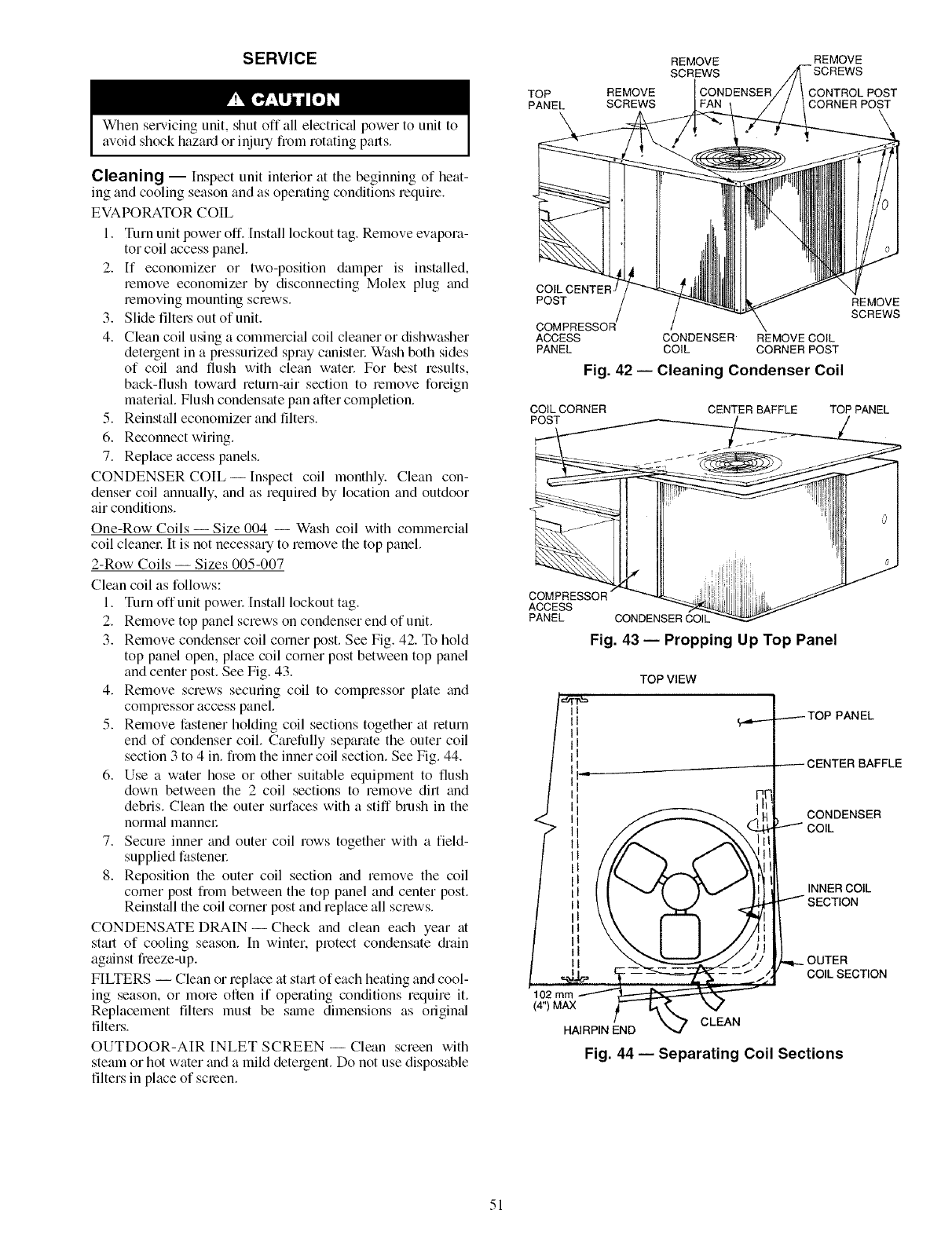
SERVICE
When servicing unit, shut off all electdcCd power to unit to
avoid shock hazard or injury fiom rotating parts.
Cleaning --Inspect unit interior at tile beginning of heat-
ing and cooling season and as operating conditions require.
EVAPORATOR COIL
1. Turn unit power off. Install lockout tag. Remove evapola-
tot coil access panel.
2. If economizer or two-position damper is installed,
remove economizer by disconnecting Molex plug and
removing mounting screws.
3. Slide filtel_ out of unit.
4. Clean coil using a commercial coil cleaner or dishwasher
detergent in a pressurized spray canistel: Wash both sides
of coil and flush with clean water. For best results,
back-flush tow_ud return-air section to remove foreign
material. Flush condensate pan after completion.
5. Reinst_dl economizer and filters.
6. Reconnect wiring.
7. Replace access panels.
CONDENSER COIL--Inspect coil monthly. Clean con-
denser coil annually, and as required by location and outdoor
air conditions.
One-Row Coils -- Size 004 -- Wash coil with commercial
coil cleanel: It is not necessary to remove the top panel.
2-Row Coils -- Sizes 005-007
Clean coil as follows:
1. Turn offunit powel: Install lockout tag.
2. Remove top panel screws on condenser end of unit.
3. Remove condenser coil corner post. See Fig. 42. To hold
top panel open, place coil corner post between top panel
and center post. See Fig. 43.
4. Remove screws securing coil to complessor plate and
compressor access panel.
5. Remove fastener holding coil sections together at return
end of condenser coil. Carefully separate the outer coil
section 3 to 4 in. from the inner coil section. See Fig. 44.
6. Use a water hose or other suitable equipment to flush
down between the 2 coil sections to remove dirt and
debris. Clean the outer surfaces with a stiff brush in the
normal mannel:
7. Secure inner and outer coil rows together with a field-
supplied fastenec
8. Reposition the outer coil section and remove the coil
comer post from between the top panel and center post.
Reinstall the coil corner post and replace all screws.
CONDENSATE DRAIN- Check and clean each year at
stml of cooling season. In winter, protect condensate di'ain
against freeze-up.
FILTERS -- Clean or replace at start of each heating and cool-
ing season, or more often if operating conditions require it.
Replacement filters must be stone dimensions as original
filters.
OUTDOOR-AIR INLET SCREEN -- Clean screen with
steam or hot water and a mild detergent. Do not use disposable
filters in place of scleen.
TOP
PANEL \
REMOVE
SCREWS
REMOVE
SCREWS
CONDENSER
REMOVE
CONTROL POST
CORNER POST
COILCENTER
POST
COMPRESSOR
ACCESS
PANEL
CONDENSER REMOVE COIL
COIL CORNER POST
Fig. 42 -- Cleaning Condenser Coil
REMOVE
SCREWS
COILCORNER
POST CENTER BAFFLE TOP PANEL
ACCESS
PANEL CONDENSER COIL
Fig. 43 -- Propping Up Top Panel
TOP VIEW
...------TOP PANEL
INNERCOIL
OUTER
COILSECTION
(4") MAX t
HAIRPIN END CLEAN
Fig. 44 -- Separating Coil Sections
51
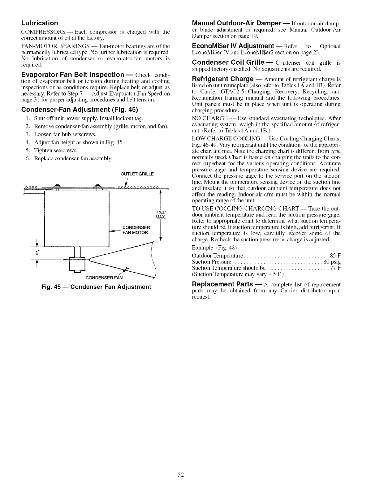
Lubrication
COMPRESSORS- Each compressor is charged with the
correct amount of oil at the factory.
FAN-MOTOR BEARINGS -- Fan-motor bearings are of the
permanently lubricated type. No further lubrication is required.
No lubrication of condenser or evaporator-fan motors is
required.
Evaporator Fan Belt Inspection -- Check condi-
tion of evaporator belt or tension dunng heating and cooling
inspections or as conditions require. Replace belt or adjust as
necessary. Refer to Step 7 -- Adjust Evaporator-Fan Speed on
page 31 for proper adjusting procedures and belt tension.
Condenser-Fan Adjustment (Fig. 45)
1. Shut offunit power supply. Install lockout tag.
2. Remove condenser-fan assembly (grille, motor, and fan).
3. Ix_osen fan hub setscrews.
4. Adjust fan height as shown in Fig. 45.
5. Tighten setscrews.
6. Replace condenser-fan assembly.
OUTLET GRILLE
1"
f
_°°°°°°°°° T
2 3/4"
MAX.
CONDENSER __
FAN MOTOR
CONDENSER FAN
Fig. 45 -- Condenser Fan Adjustment
Manual Outdoor-Air Damper -- If outdoor-air damp-
er blade adjustment is required, see Manual Outdoor-Air
Damper section on page 19.
EconoMiSer IVAdjustment -- Refer to Optional
EconoMiSer [V and EconoMi$er2 section on page 23.
Condenser Coil Grille-- Condenser coil grille is
shipped factory-installedi No adjustments are required.
Refrigerant Charge -- Amount of refrigerant charge is
listed on unit nameplate (also refer to Tables 1A and 1B). Refer
to Carrier GTAC2-5 Charging, Recovery, Recycling, and
Reclamation training manual and the following procedures.
Unit panels must be in place when unit is operating during
ch_uging procedure.
NO CHARGE -- Use standard evacuating techniques. After
ew_cuating system, weigh in the specified amount of refriger-
ant. (Refer to Tables IA and lB.)
LOW CHARGE COOLING -- Use Cooling Ch;u'ging Charts,
Fig. 46-49. Vary refrigerant until the conditions of the appropri-
ate chart am met. Note the charging chart is different from type
norm_dly used. Chmt is based on chalging the units to the cor-
rect superheat for the vtuious operating conditions. Accurate
pressure gage and temperature sensing device ;ue required.
Connect the pressure gage to the service port on the suction
line. Mount the temperature sensing device on the suction line
and insulate it so that outdoor ambient temperature does not
affect the reading. Indoor-air cfln must be within the normal
operating range of the unit.
TO USE COOLING CHARGING CHART- Take the out-
door ambient temperature and read the suction pressure gage.
Refer to appropriate chart to determine what suction tempera-
ture should be. If suction temperature is high, add refrigerant. If
suction temperature is low, carelidly recover some of the
chtuge. Recheck the suction pressure as charge is adjusted.
Example: (Fig. 48)
Outdoor Temperature .............................. 85 F
Suction Pressure ............................... 80 psig
Suction Temperature should be ...................... 77 F
(Suction Temperature may v;u-y _+5 E)
Replacement Parts -- A complete list of replacement
parts may be obtained flom any Canier distributor upon
request.
52
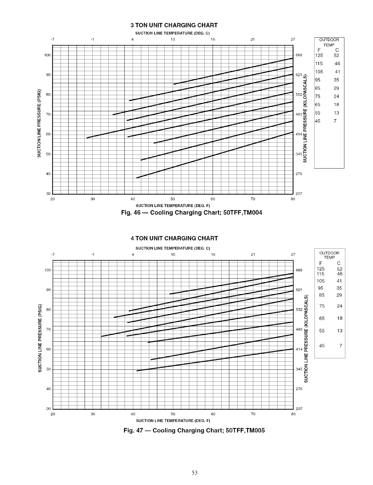
-7
I O0
9O
-- 80
w
m 7o
w
w
z
-- 6o
._1
z
_.q
I--
_ 5o
4o
3TON UNIT CHARGING CHART
SUCTION LINE TEMPERATURE (DEG. C)
4 10 16 21 OUTDOOR
TEMP
F C
125 52
115 46
105 41
95 35
85 29
75 24
65 18
55 13
45 7
276
30
20 30 40 50 60 70
SUCTION LINE TEMPERATURE (DEG. F)
Fig. 46- Cooling Charging Chart; 50TFF,TMO04
207
80
-7
I00
90
80
w
_ 7o
w
w
z
_ 60
z
0
_ 5o
40
4 TON UNIT CHARGING CHART
SUCTION LINE TEMPERATURE (DEG. C)
4 10 16 27
! ZZ ZZ
_ 345 --
I--
276
OUTDOOR
TEMP
F C
125 52
115 46
105 41
95 35
85 29
75 24
65 18
55 13
45 7
30
20 40 50 60 70
SUCTION LINE TEMPERATURE (DEG. F)
Fig. 47 -- Cooling Charging Chart; 50TFF,TMO05
207
80
53
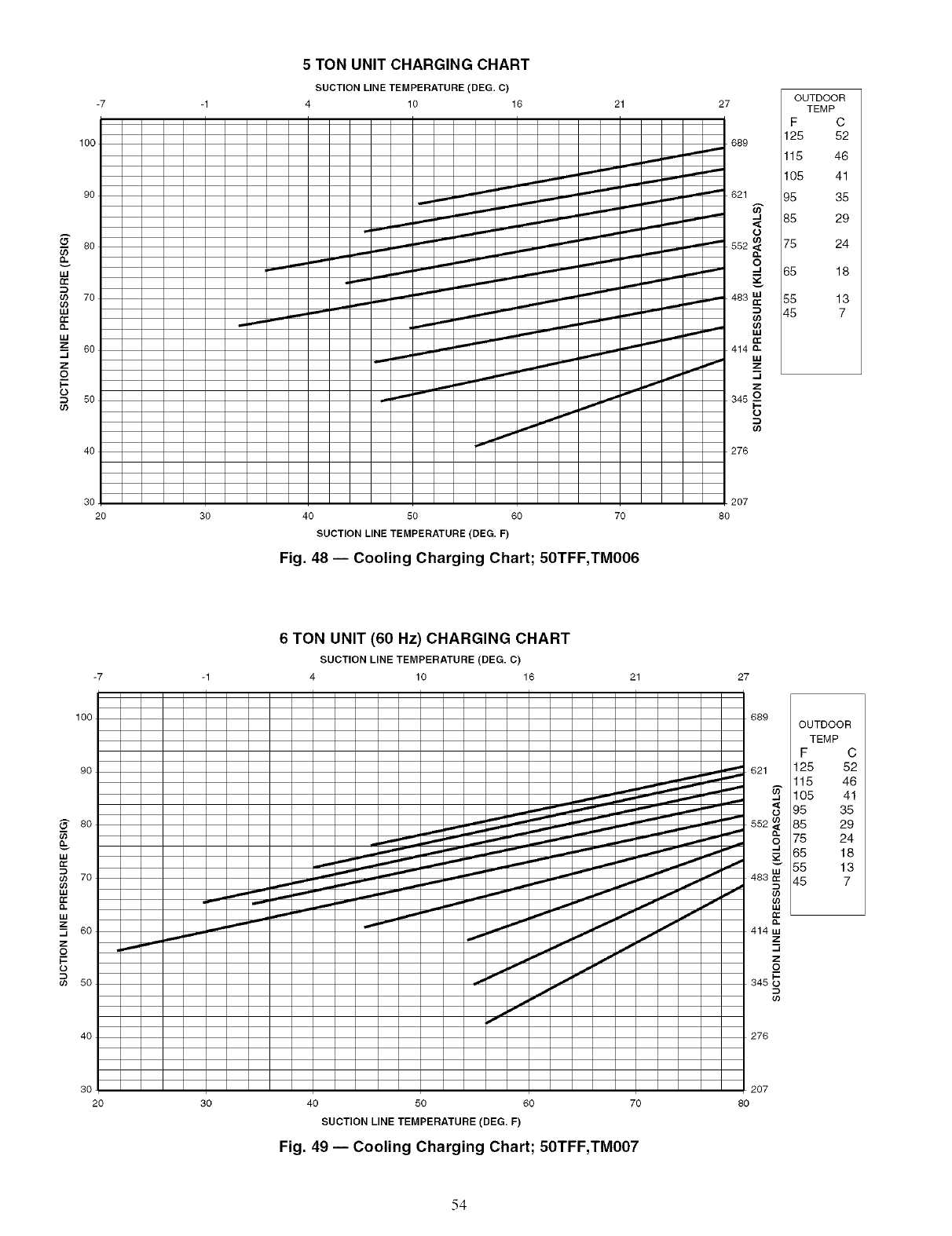
69
O.
#J
n-
69
69
#J
n-
O.
#J
_z
_J
z
_o
F-
O
69
-7
100
5 TON UNIT CHARGING CHART
SUCTION LINE TEMPERATURE (DEG. C) F TEMPc
-1 4 10 16 21 27 OUTDOOR
125 52
_- 689 115 46
-_ 105 41
_'_ 621 95 35
_._ ...- --_ -_ -J 85 29
..,,.- ,,'_ ""-_ '--- "" "" -"" -_" .,-- o 75 24
_ 65 18
_ _ 483
,.,,,,,,_,,,,,,,,_ ,,...,.., _' 414 a,,
-n
_ ""_ .._,_ r_' 345 __
276
30 207
20 30 40 50 60 70 80
SUCTION LINE TEMPERATURE (DEG. F)
Fig. 48 -- Cooling Charging Chart; 50TFF,TMO06
6TON UNIT (60 Hz) CHARGING CHART
SUCTION LINE TEMPERATURE (DEG. C)
-7 -1 4 10 16 21 27
IO0
4O
OUTDOOR
TEMP
F C
125 52
115 46
105 41
95 35
85 29
75 24
65 18
55 13
45 7
o.
414 m
z
..J
z
1-
345 0
o3
276
3O
20 30 40 50 60 70
SUCTION LINE TEMPERATURE (DEG. F)
Fig. 49 -- Cooling Charging Chart; 50TFF,TMO07
207
8O
54
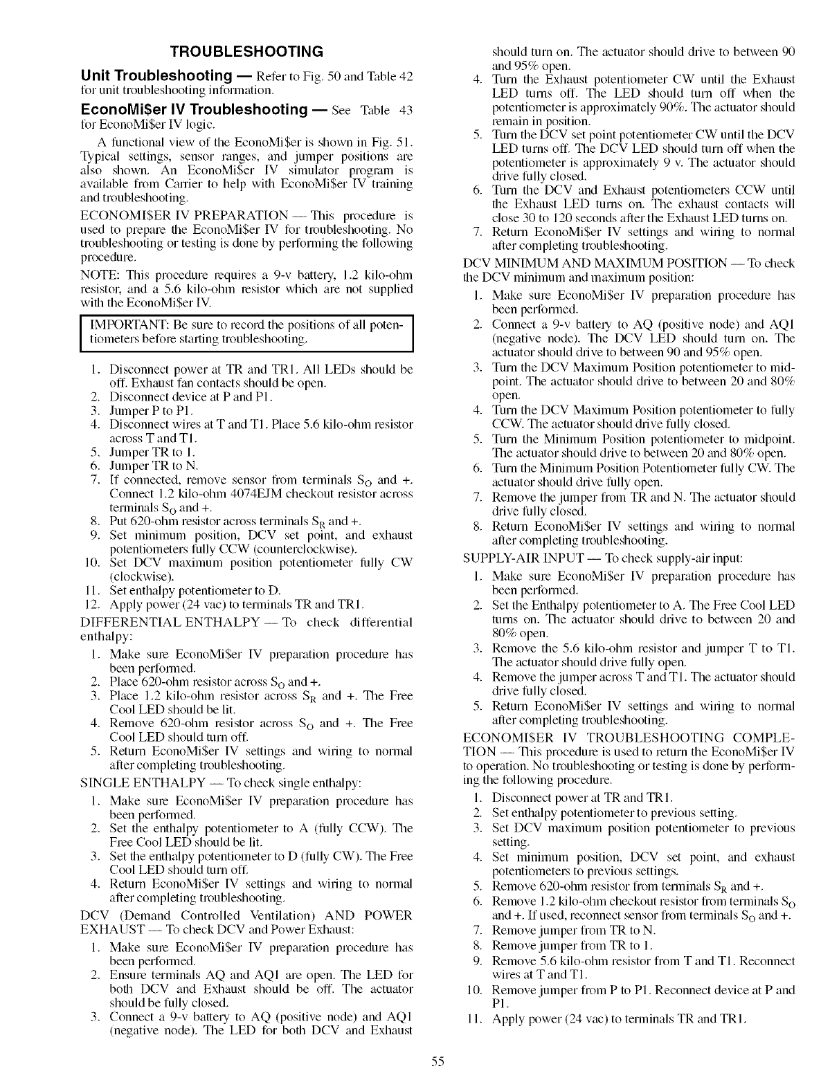
TROUBLESHOOTING
Unit Troubleshooting -- Refer to Fig. 50 and Table 42
for unit troubleshooting information.
EconoMiSer IV Troubleshooting -- See Table 43
for EconoMiSer IV logic.
A functional view of the EconoMiSer is shown in Fig. 51.
Typical settings, sensor lunges, and jumper positions are
also shown. An EconoMiSer IV simukitor proglam is
available from Carrier to help with EconoMiSer IV training
and troubleshooting.
ECONOMISER IV PREPARATION -- This procedure is
used to prepare the EconoMi$er IV for troubleshooting. No
troubleshooting or testing is done by performing the following
procedure.
NOTE: This procedure requires a 9-v battery. 1.2 kilo-ohm
resistok and a 5.6 kilo-ohm resistor which are not supplied
with the EconoMi$er IV.
lIMPORTANT: Be sure to record the positions of all poten-tiometers before starting troubleshooting.
1. Disconnect power at TR and TRI. All LEDs should be
off. Exhaust fan contacts should be open.
2. Disconnect device at P and PI.
3. Jumper P to PI.
4. Disconnect wires at T and TI. Place 5.6 kilo-ohm resistor
across T and TI.
5. Jumper TR to 1.
6. Jumper TR to N.
7. If connected, remove sensor from terminals So and +.
Connect 1.2 kilo-ohm 4074EJM checkout resistor across
terminals S o and +.
8. Put 620-ohm resistor across terminals SR and +.
9. Set minimum position, DCV set point, and exhaust
potentiometers fully CCW (counterclockwise).
10. Set DCV maximum position potentiometer lillly CW
(clockwise).
11. Set enthalpy potentiometer to D.
12. Apply power (24 vac) to termimds TR and TRI.
DIFFERENTIAL ENTHALPY-- To check differential
enthalpy:
1. Make sure EconoMiSer IV prepmation procedure has
been performed.
2. Place 620-ohm resistor across So and +.
3. Pkice 1.2 kilo-ohm resistor across SR and +. The Free
Cool LED should be lit.
4. Remove 620-ohm resistor across S o and +. The Free
Cool LED should turn off.
5. Return EconoMi$er IV settings and wiring to normal
after completing troubleshooting.
SINGLE ENTHALPY -- To check single enth_dpy:
1. Make sure EconoMiSer IV prepmation procedure has
been performed.
2. Set the enthalpy potentiometer to A (fully CCW). The
Flee Cool LED should be lit.
3. Set the enthalpy potentiometer to D (fully CW). The Free
Cool LED should turn off.
4. Return EconoMiSer IV settings and wiring to normal
after completing troubleshooting.
DCV (Demand Controlled Ventilation) AND POWER
EXHAUST -- To check DCV and Power Exhaust:
1. Make sum EconoMiSer IV pmpmation procedure has
been performed.
2. Ensure terminals AQ and AQI are open. The LED for
both DCV and Exhaust should be off. The actuator
should be fully closed.
3. Connect a 9-v battery to AQ (positive node) and AQI
(negative node). The LED for both DCV and Exhaust
should turn on. The actuator should drive to between 90
and 95% open.
4. Turn the Exhaust potentiometer CW until the Exhaust
LED turns off. The LED should turn off when the
potentiometer is approximately 90%. The actuator should
remain in position.
5. Turn the DCV set point potentiometer CW until the DCV
LED turns off. The DCV LED should turn off when the
potentiometer is approximately 9 v. The actuator should
&'ive fully closed.
6. Turn the DCV and Exhaust potentiometers CCW until
the Exhaust LED turns on. The exhaust contacts will
close 30 to 120 seconds after the Exhaust LED turns on.
7. Return EconoMiSer IV settings and wiling to normal
after completing troubleshooting.
DCV MINIMUM AND MAXIMUM POSITION -- To check
the DCV minimum and maximum position:
1. Make sure EconoMiSer IV preparation procedure has
been performed.
2. Connect a 9-v batte qto AQ (positive node) and AQI
(negative node). The DCV LED should turn on. The
actuator should drive to between 90 and 95% open.
3. Turn the DCV Maximum Position potentiometer to mid-
point. The actuator should drive to between 20 and 80%
open.
4. Turn the DCV Maximum Position potentiometer to fully
CCW. The actuator should drive fully closed.
5. Turn the Minimum Position potentiometer to midpoint.
The actuator should drive to between 20 and 80% open.
6. Turn the Minimum Position Potentiometer fully CW. The
actuator should drive fully open.
7. Remove the jumper from TR and N. The actuator should
drive fully closed.
8. Return EconoMiSer IV settings and wiling to normal
after completing troubleshooting.
SUPPLY-AIR INPUT -- To check supply-air input:
1. Make sure EconoMiSer IV preparation procedure has
been performed.
2. Set the Enthalpy potentiometer to A. The Free Cool LED
turns on. The actuator should drive to between 20 and
80% open.
3. Remove the 5.6 kilo-ohm resistor and jumper T to TI.
The actuator should drive fully open.
4. Remove the jumper across T and TI. The actuator should
drive fully closed.
5. Return EconoMi$er IV settings and wiling to normal
after completing troubleshooting.
ECONOMI$ER IV TROUBLESHOOTING COMPLE-
TION -- This procedure is used to return the EconoMi$er IV
to operation. No troubleshooting or testing is done by perform-
ing the following procedure.
1. Disconnect power at TR and TRI.
2. Set enthalpy potentiometer to previous setting.
3. Set DCV maximum position potentiometer to previous
setting.
4. Set minimum position, DCV set point, and exhaust
potentiometel.s to previous settings.
5. Remove 620-ohm resistor from terminals SR and +.
6. Remove 1.2 kilo-ohm checkout resistor flom terminals SO
and +. [f used, reconnect sensor flom terminals SOand +.
7. Remove jumper from TR to N.
8. Remove jumper from TR to 1.
9. Remove 5.6 kilo-ohm resistor fiom T and TI. Reconnect
wires at T and TI.
10. Remove jumper flom P to PI. Reconnect device at P and
PI.
11. Apply power (24 vac) to terminals TR and TRI.
55
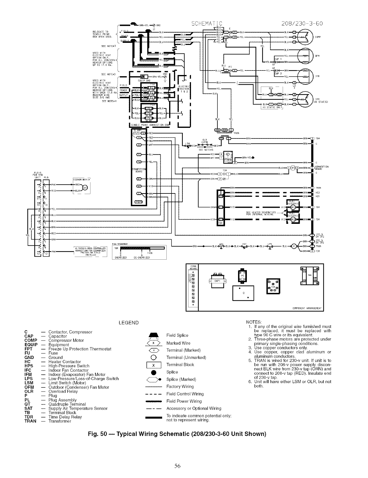
PL6 R
FOR 5TD
UNIT PLG
.--(_
Y
.--(_
SEE NOTE_3
USEB WITH I I
ELECTRIC HEAT
OPTION ONLY, FIELB
FOR ALL 208/230V
HEATER OPTIONS POWER
WITH OVER 17.0 KW I
MAXIMUM WIRE SUPPLY
51ZE 2/0 AWG I
SEE NOTE#4
ECONOMIZER
-PNK RED
SCHEMATIC
BLK
_'BLK_ c
--BLK C
YEL
_Z_ y EL ,_,ly _ L
I
208/230 3 60
BLK_
h -u .......
BLU QT
.... _ ........ _BRN_
----_LKYEL_ | L BLU[BLuB& _BLU 3
I1 / , ......
,BRNI ] TB4
,BRNI C
C
CONNECTION
}BOARO
C
) TRAN
HC2
HCl
] TB4
] TB4
[FC,3
BRN-- )OR IFC
IFC 3
)OR IFC
) TRAN
} Tun
CONN
BOARO
=U_
[]
[]
[]
[]
[]
C I
CAP --
COMP --
EQUIP --
FPT --
FU
GND --
HC
HPS --
IFC --
IFM --
LPS --
LSM --
OFM --
OLR --
p
PL
QT
SAT --
TB
TDR --
TRAN --
LEGEND
Contactor, Compressor
Capacitor
Compressor Motor
Equipment
Freeze Up Protection Thermostat
Fuse
Ground
Heater Contactor
High-Pressure Switch
Indoor Fan Contactor
Indoor (Evaporator) Fan Motor
Low-Pressure/Loss-of-Charge Switch
Limit Switch (Motor)
Outdoor (Condenser) Fan Motor
Overload Relay
Plug
Plug Assembly
Quadruple Terminal
Supply Air Temperature Sensor
Terminal Block
Time Delay Relay
Transformer
Field Splice
Marked Wire
Terminal (Marked)
0Terminal (Unmarked)
[_ Terminal Block
• Splice
Splice (Marked)
Factory Wiring
Field Control Wiring
Field Power Wiring
Accessory or Optional Wiring
i To indicate common potential only;
not to represent wiring.
NOTES:
1, If any of the original wire furnished must
be replaced, it must be replaced with
type 90 C wire or its equivalent.
2, Three-phase motors are protected under
primary single-phasing conditions.
3, Use copper conductors only.
4, Use copper, copper clad aluminum or
aluminum conductors.
5, TRAN is wired for 230-v unit. If unit is to
be run with 208-v power supply discon-
nect BLK wire from 230-v tap (ORN) and
connect to 208-v tap (RED). Insulate end
of 230-v tap.
6, Unit will have either LSM or OLR, but not
both.
Fig. 50 -- Typical Wiring Schematic (208/230-3-60 Unit Shown)
56
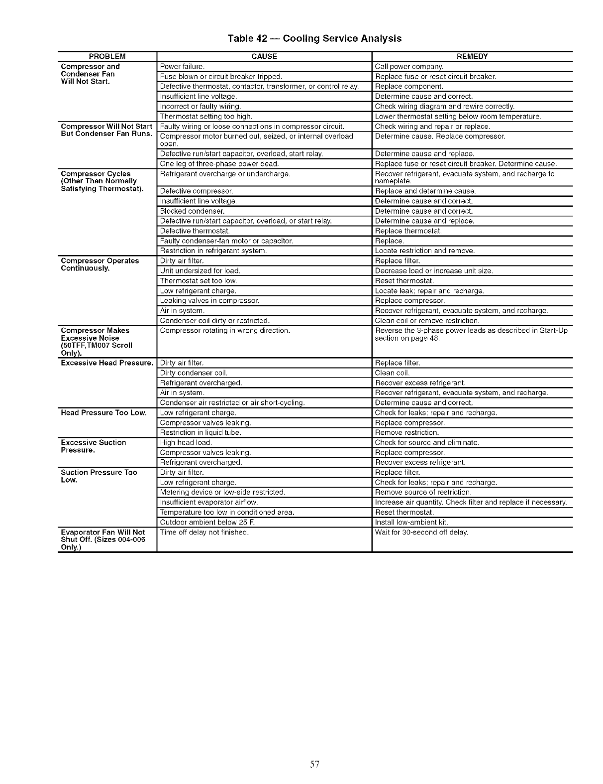
Table 42 -- Cooling Service Analysis
PROBLEM CAUSE REMEDY
Compressor and Power failure. Call power company.
Condenser Fan Fuse blown or circuit breaker tripped. Replace fuse or reset circuit breaker.
Will Not Start. Defective thermostat, contactor, transformer, or control relay. Replace component.
Insufficient line voltage. Determine cause and correct.
Incorrect or faulty wiring. Check wiring diagram and rewire correctly.
Thermostat setting too high. Lower thermostat setting below room temperature.
Compressor Will Not Start Faulty wiring or loose connections in compressor circuit. Check wiring and repair or replace.
But Condenser Fan Runs. Compressor motor burned out, seized, or internal overload Determine cause. Replace compressor.
open.
Defective run/start capacitor, overload, start relay. Determine cause and replace.
One leg of three-phase power dead. Replace fuse or reset circuit breaker. Determine cause.
Compressor Cycles Refrigerant overcharge or undercharge. Recover refrigerant, evacuate system, and recharge to
(Other Than Normally nameplate.
Satisfying Thermostat). Defective compressor. Replace and determine cause.
Insufficient line voltage. Determine cause and correct.
Blocked condenser. Determine cause and correct.
Defective run/start capacitor, overload, or start relay. Determine cause and replace.
Defective thermostat. Replace thermostat.
Faulty condenser-fan motor or capacitor. Replace.
Restriction in refrigerant system. Locate restriction and remove.
Compressor Operates Dirty air filter. Replace filter.
Continuously. Unit undersized for load. Decrease load or increase unit size.
Thermostat set too low. Reset thermostat.
Low refrigerant charge. Locate leak; repair and recharge.
Leaking valves in compressor. Replace compressor.
Air in system. Recover refrigerant, evacuate system, and recharge.
Condenser coil dirty or restricted. Clean coil or remove restriction.
Compressor Makes Compressor rotating in wrong direction. Reverse the 3-phase power leads as described in Start-Up
Excessive Noise section on page 48.
(50TFF, TMO07 Scroll
Only).
Excessive Head Pressure. Dirty air filter. Replace filter.
Dirty condenser coil. Clean coil.
Refrigerant overcharged. Recover excess refrigerant.
Air in system. Recover refrigerant, evacuate system, and recharge.
Condenser air restricted or air short-cycling. Determine cause and correct.
Head Pressure Too Low. Low refrigerant charge. Check for leaks; repair and recharge.
Compressor valves leaking. Replace compressor.
Restriction in liquid tube. Remove restriction.
Excessive Suction High head load. Check for source and eliminate.
Pressure. Compressor valves leaking. Replace compressor.
Refrigerant overcharged. Recover excess refrigerant.
Suction Pressure Too Dirty air filter. Replace filter.
Low. Low refrigerant charge. Check for leaks; repair and recharge.
Metering device or low-side restricted. Remove source of restriction.
Insufficient evaporator airflow. Increase air quantity. Check filter and replace if necessary.
Temperature too low in conditioned area. Reset thermostat.
Outdoor ambient below 25 E Install low-ambient kit.
Evaporator Fan Will Not Time off delay not finished. Wait for 30-second off delay.
Shut Off. (Sizes 004-006
Only.)
57

Table 43 -- EconoMi$er IV Input/Output Logic
Demand Control
Ventilation (DCV)
Below set
(DCV LED Off)
Above set
(DCV LED On)
INPUTS
Enthalpy* Compressor
Outdoor Return Y1 Y2 Stage Stage
1 2
High Low On On On On
(Free Cooling LED Off) On Off On Off
Off Off Off Off
Low High On On On Off
(Free Cooling LED On) On Off Off Off
Off Off Off Off
High Low On On On On
(Free Cooling LED Off) On Off On Off
Off Off Off Off
Low High On On On Off
(Free Cooling LED On) On Off Off Off
Off Off Off Off
*For single enthalpy control, the module compares
enthalpy to the ABCD set point.
tPower at N terminal determines Occupied/Unoccupied
24 vac (Occupied), no power (Unoccupied).
**Modulation is based on the supply-air sensor signal.
1-tModulation is based on the DCV signal.
OUTPUTS
NTerminalt
Occupied
Minimum position
Modulating** (between min.
position and full-open)
Minimum position
Modulating1-1- (between min.
position and DCV maximum)
Modulating***
Unoccupied
Dam )er
Closed
Modulating** (between
closed and full-open)
Closed
Modulatingtl- (between
closed and DCV
maximum)
Modulatingtl-t
outdoor
setting:
***Modulation is based on the greater of DCV and supply-air sen-
sor signals, between minimum position and either maximum
position (DCV) or fully open (supply-air signal).
ttl-Modulation is based on the greater of DCV and supply-air sen-
sor signals, between closed and either maximum position (DCV)
or fully open (supply-air signal).
Fig. 51 -- EconoMi$er IV Functional View
58
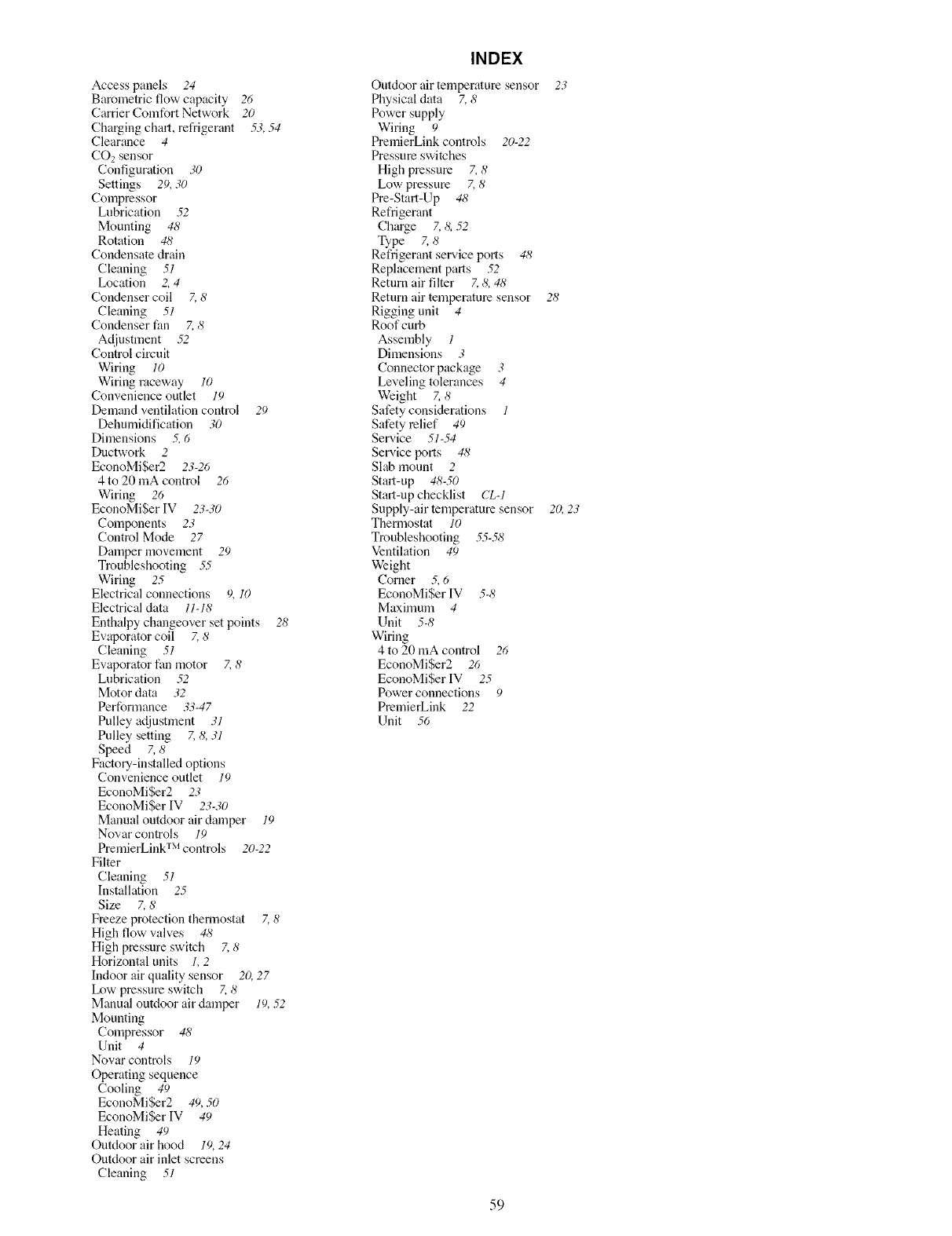
Access panels 24
Barometric flow capacity 26
Carrier Comfort Network 20
Charging chart, refrigerant 53,.54
Clearance 4
CO2sensor
Configuration 30
Settings 29,30
Compressor
Lubrication .52
Mounting 48
Rotation 48
Condensate drain
Cleaning 51
Location 2,4
Condenser coil Z 8
Cleaning 51
Condenser fan Z 8
Adjustment .52
Control circuit
Wiring 10
Wiring raceway 10
Convenience outlet 19
Demand ventilation control 29
Dehumidification 30
Dimensions 5, 6
Dnctwork 2
EconoMiSer2 23-26
4 to 20 mA control 26
Wiring 26
EconoMiSer IV 23-30
Components 23
Control Mode 27
Damper movement 29
Troubleshooting .5.5
Wiring 25
Electrical connections 9, 10
Electrical data 11-18
Enthalpy changeover set points 28
Evaporator coil Z 8
Cleaning 51
Ewtporator fan motor 7,8
Lubrication .52
Motor data 32
Performance 33-47
Pulley adjustment 31
Pulley setting Z 8, 31
Speed 7,8
Factou-installed options
Convenience outlet 19
EconoMiSer2 23
EconoMiSer IV 23-30
Manual outdoor air damper 19
Novar controls 19
PremierLink TM controls 20-22
Filter
Cleaning 51
Installation 25
Size 7, 8
Freeze protection thermostat Z8
High flow valves 48
High pmssnre switch Z 8
Horizontal units 1, 2
Indoor air qnality sensor 20,27
Ix_w pressure switch Z 8
Manual outdoor air damper 19,.52
Mounting
Compressor 48
Unit 4
Nowtr controls 10
Operating sequence
Cooling 40
EconoMiSer2 49,50
EconoMiSer IV 49
Heating 49
Ontdoor air hood 19,24
Ontdoor air inlet screens
Cleaning 51
INDEX
Ontdoor air temperature sensor 23
Physical data 7, 8
Power supply
Wiring 9
PremierLink controls 20-22
Pressure switches
High pressure 7, 8
Low pressure Z 8
Pre-Start-Up 48
Refrigerant
Charge 7, 8, 52
Type 7, 8
Refrigerant ser_.ice ports 48
Replacement parts .52
Retnrn air filter Z 8, 48
Return air tempemtnre sensor 214
Rigging unit 4
Roof curb
Assembly 1
Dimensions 3
Connector package 3
Leveling tolerances 4
Weight Z 8
Safety considerations 1
Safety relief 49
Ser_.ice 51-.54
Service lx_rts 41_
Slab mount 2
Start-up 48-50
Start-up checklist CL-1
Snpply-air temperature sensor 20,23
Thermostat 10
Troubleshooting 55-51_
Ventilation 49
Weight
Corner 5, 6
EconoMiSer IV 5-8
Maximum 4
Unit 5-8
Wiring
4 to 20 mA control 26
EconoMiSer2 26
EconoMiSer IV 25
Power connections 9
PremierLink 22
Unit 56
59
SERVICE TRAINING
Packaged Service Training programs are an excellent way to increase your knowledge of the equipment
discussed in this manual, including:
• Unit Familiarization
• Installation Overview
• Maintenance
• Operating Sequence
Ahu'ge selection of product, theory, and skills programs are available, using popuhu video-based formats
and materials. All include video and/or slides, plus companion book.
Classroom Service Training which includes "hands-on" experience with file products in our labs can
mean increased confidence that really pays dividends in faster troubleshooting and fewer callbacks. Course
descriptions and schedules are in our catalog.
CALL FOR FREE CATALOG 1-800-644-5544
] Packaged Service Training [ ] Classroom Service Training
Copyright 2005 Carrier Corporation
Manufacturer reserves the right to discontinue, or change at any time, specifications or designs without notice and without incurring obligations.
Catalog No. 04-53500010-01 Printed in U.S.A. Form 50T-5SI Pg 60 9-05 Replaces: 50T-3SI
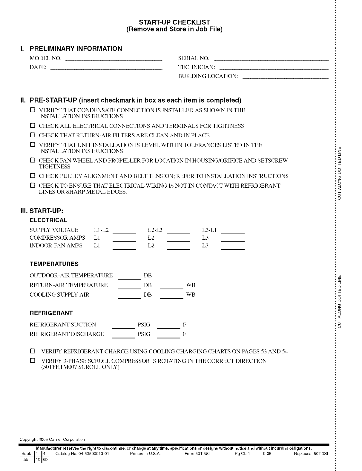
START-UP CHECKLIST
(Remove and Store in Job File)
PRELIMINARY INFORMATION
MODEL NO.
DATE:
SERIAL NO.
TECHNICIAN:
BUILDING LOCATION:
II. PRE-START-UP (insert checkmark in box as each item is completed)
[] VERIFY THAT CONDENSATE CONNECTION IS INSTALLED AS SHOWN IN THE
INSTALLATION INSTRUCTIONS
[] CHECK ALL ELECTRICAL CONNECTIONS AND TERMINALS FOR TIGHTNESS
[] CHECK THAT RETURN-AIR FILTERS ARE CLEAN AND IN PLACE
[] VERIFY THAT UNIT INSTALLATION IS LEVEL WITHIN TOLERANCES LISTED IN THE
INSTALLATION INSTRUCTIONS
[] CHECK FAN WHEEL AND PROPELLER FOR LOCATION IN HOUSING/ORIFICE AND SETSCREW
TIGHTNESS
[] CHECK PULLEY ALIGNMENT AND BELT TENSION; REFER TO INSTALLATION INSTRUCTIONS
[] CHECK TO ENSURE THAT ELECTRICAL WIRING IS NOT IN CONTACT WITH REFRIGERANT
LINES OR SHARP METAL EDGES.
III. START-UP:
ELECTRICAL
SUPPLY VOLTAGE LI-L2 L2-L3 L3-LI
COMPRESSOR AMPS LI L2 L3
INDOOR-FAN AMPS LI L2 L3
TEMPERATURES
OUTDOOR-AIR TEMPERATURE
RETURN-AIR TEMPERATURE
COOLING SUPPLY AIR
DB
DB WB
DB WB
REFRIGERANT
REFRIGERANT SUCTION
REFRIGERANT DISCHARGE
PSIG F
PSIG F
[] VERIFY REFRIGERANT CHARGE USING COOLING CHARGING CHARTS ON PAGES 53 AND 54
[] VERIFY 3-PHASE SCROLL COMPRESSOR IS ROTATING IN THE CORRECT DIRECTION
(50TFKTM007 SCROLL ONLY)
Copyright 2005 Carrier Corporation
Manufacturer reserves the right to discontinue, or change at any time, specifications or designs without notice and without incurring obligations.
Book 1 [4 Catalog No, 04-53500010-01 Printed in U.S,A. Form 50T-5SI Pg CL-1 9-05 Replaces: 50T-3SI
Tab 1b 16b
LU
2:
m
c_
LU
I--
rm
Z
o,
<
I-
(p
LU
2:
m
rm
LU
I-
c_
Z
o,
<
I-
(p
