CARRIER Evaporator Coils Manual L0521268
AQUAFORCE 30XA080-500 L0521268
User Manual: CARRIER CARRIER Evaporator Coils Manual CARRIER Evaporator Coils Owner's Manual, CARRIER Evaporator Coils installation guides
Open the PDF directly: View PDF ![]() .
.
Page Count: 44
AQUAFORCE TM
30XA080-500
Air-Cooled Liquid Chillers
Installation Instructions
CONTENTS
Page
SAFETY CONSIDERATIONS ...................... 1
INTRODUCTION .................................. 1
INSTALLATION ................................ 2-42
Storage .......................................... 2
Step 1 -- Inspect Shipment ...................... 2
Step 2 -- Place, Mount and Rig Unit ............. 2
• PLACING UNIT
• MOUNTING UNIT
• RIGGING UNIT
Step 3 -- Cooler Fluid and Drain Piping
Connections .................................. 29
• GENERAL
• DUAL CHILLER CONTROL
• COOLER FLUID, VENT. AND DRAIN
•COOLER PUMP CONTROL
• BRINE UNITS
• WATER TREATMENT
• PREPARATION FOR YEAR-ROUND OPERATION
• PREPARATION FOR WINTER SHUTDOWN
Step 4-- Make Electrical Connections .......... 34
• POWER SUPPLY
• FIELD POWER CONNECTIONS
• FIELD CONTROL POWER CONNECTIONS
• CARRIER COMFORT NETWORK
COMMUNICATION BUS WIRING
• NON-CCN COMMUNICATION WIRING
• FIELD CONTROL OPTION WIRING
• DUAL CHILLER LEAVING WATER SENSOR
Step 5-- Install Accessories .................... 41
•ENERGY MANAGEMENT MODULE
• REMOTE ENHANCED DISPLAY
• LOW AMBIENT TEMPERATURE OPERATION
• MINIMUM LOAD ACCESSORY
• UNITSECURITY/PROTECTION ACCESSORIES
• COMMUNICATION ACCESSORIES
• SERVICE OPTIONS
• CONTROL TRANSFORMER
Step 6 -- Leak Test Unit ......................... 41
Step 7 -- Refrigerant Charging .................. 41
•DEHYDRATION
• REFRIGERANT CHARGE
SAFETY CONSIDERATIONS
Installing, starting up, and servicing this equipment can be
haz_u'dousdue to system pressures, electric_d components, and
equipment location. Only trained, qu_difiedinst_dlersand service
mechanics should inst_dl,stall up, and service this equipment.
When working on the equipment, observe precautions in the
literature, and on tags, stickers, and labels attached to the
equipment.
• Follow all safety codes.
• Wear safety glasses and work gloves.
• Use care in handling, rigging, and setting bulky equipment.
Electfic_d shock can cause persomd injury and death. Shut
off all power to this equipment during installation. There
may be more than one disconnect switch. Ntg all discon-
nect locations to _dert others not to restore power until work
is completed.
IMPORTANT: This equipment generates, uses, and
can radiate radio frequency energy and if not installed
and used in accordance with these instructions may
cause radio interference. It has been tested and found
to comply with the limits of a Class A computing
device as defined by FCC (Federal Communications
Commission, U.S.A.) regulations, Subpart J of Part 15,
which are designed to provide reasonable protection
against such interference when operated in a commer-
cial environment.
INTRODUCTION
These instructions cover installation of 30XA080-500 air-
cooled liquid chillers with electronic controls and units with
factory-installed options (FIOPs). See Fig. 1.
Manufacturer reserves the right to discontinue, or change at any time, specifications or designs without notice and without incurring obligations.
PC 903 Catalog No. 533-00068 Printed in U.S.A. Form 30XA-1SI Pg 1 6-05 Replaces: New
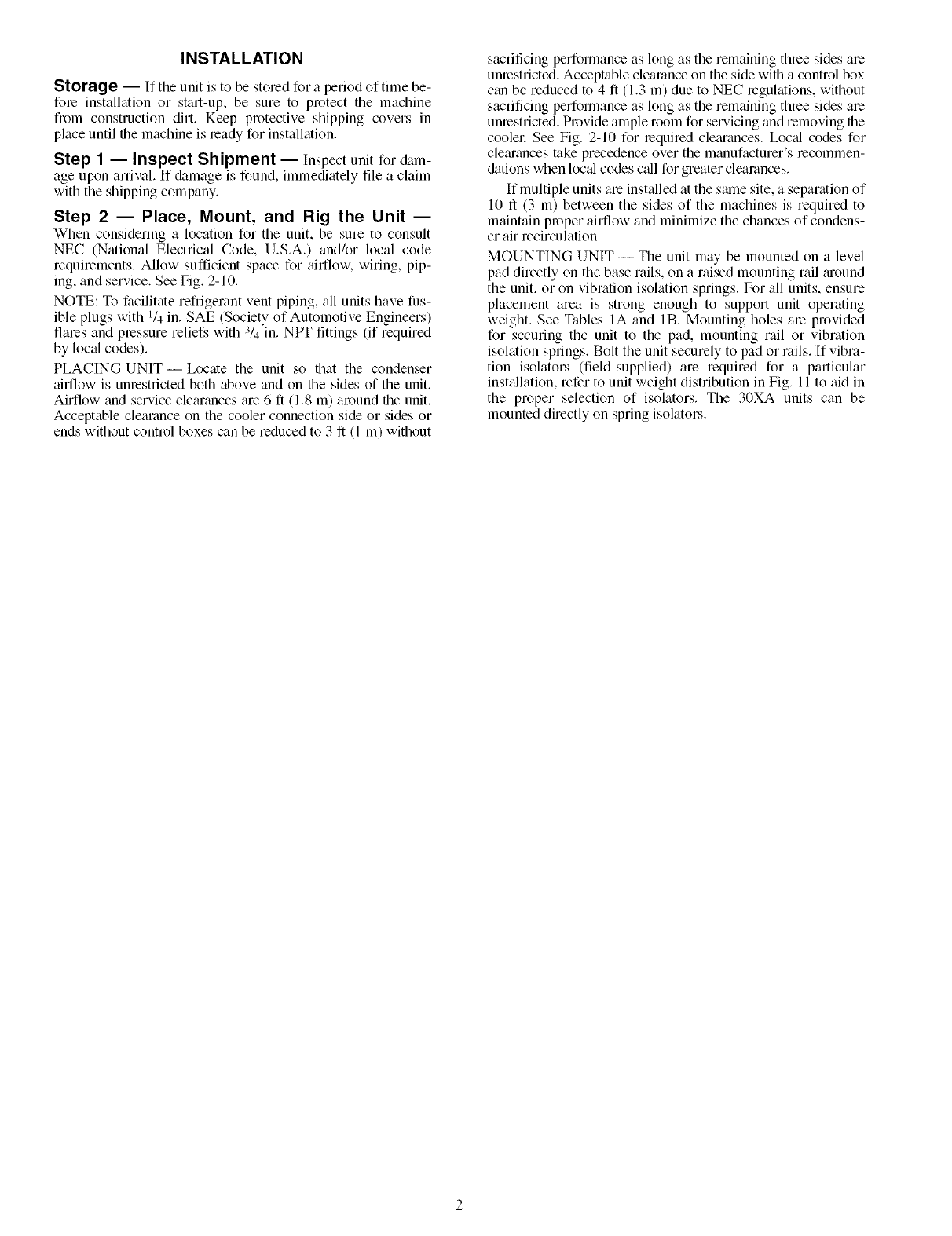
INSTALLATION
Storage -- If the unit is to be stored for a period of time be-
fore installation or start-up, be sure to protect file machine
from construction dirt. Keep protective shipping covers in
place until file machine is ready for installation.
Step 1 -- Inspect Shipment -- Inspect unit for &im-
age upon arrival. If &image is found, immediately file a claim
with the shipping company.
Step 2 -- Place, Mount, and Rig the Unit --
When considering a location for the unit, be sure to consult
NEC (National Electrical Code, U.S.A.) and/or local code
requirements. Allow sufficient space for airtlow, wiring, pip-
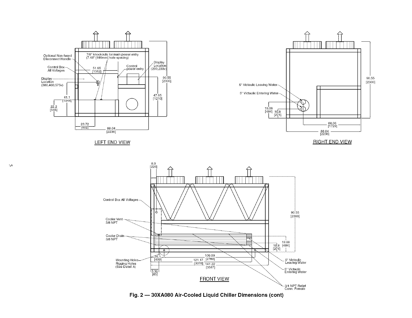
ing, and service. See Fig. 2-10.
NOTE: To facilitate refrigerant vent piping, all units have fus-
ible plugs with 1/4 in. SAE (Society of Automotive Engineers)
flares and pressure reliefs with 3/4 in. NPT fittings (if required
by locfd codes).
PLACING UNIT--Ix_cate the unit so that the condenser
airtlow is unrestricted both above fred on the sides of the unit.
Airflow find service clefuances me 6 fl (1.8 m) around file unit.
Acceptable clearance on the cooler connection side or sides or
ends without control boxes can be reduced to 3 ft (1 m) without
sacrificing performance as long as the remaining three sides me
unrestricted. Acceptable clearance on the side wifll a control box
cfm be reduced to 4 fl (1.3 m) due to NEC regulations, without
sacrificing performance as long as the remaining three sides am
unrestricted. Provide ample room for servicing find removing file
cooler See Fig. 2-10 for lequimd clemances. Ix)cffl codes for
clem'ances take precedence over the manufacturer's mcommen-
c_kLtions when locfd codes cfdl for greater clearances.
If multiple units am installed at the stone site, a separation of
10 fl (3 m) between the sides of the machines is required to
maintain proper airflow and minimize the chances of condens-
er air recimulation.
MOUNTING UNIT -- The unit may be mounted on a level
pad directly on the base rails, on a raised mounting rail m'ound
the unit, or on vibration isolation springs. For all units, ensure
placement area is strong enough to suppori unit operating
weight. See Tables IA and lB. Mounting holes are provided
for securing the unit to the pad, mounting rail or vibration
isolation springs. Bolt the unit securely to pad or rails. [f vibra-
tion isolatol.'s (field-supplied) are required for a particular
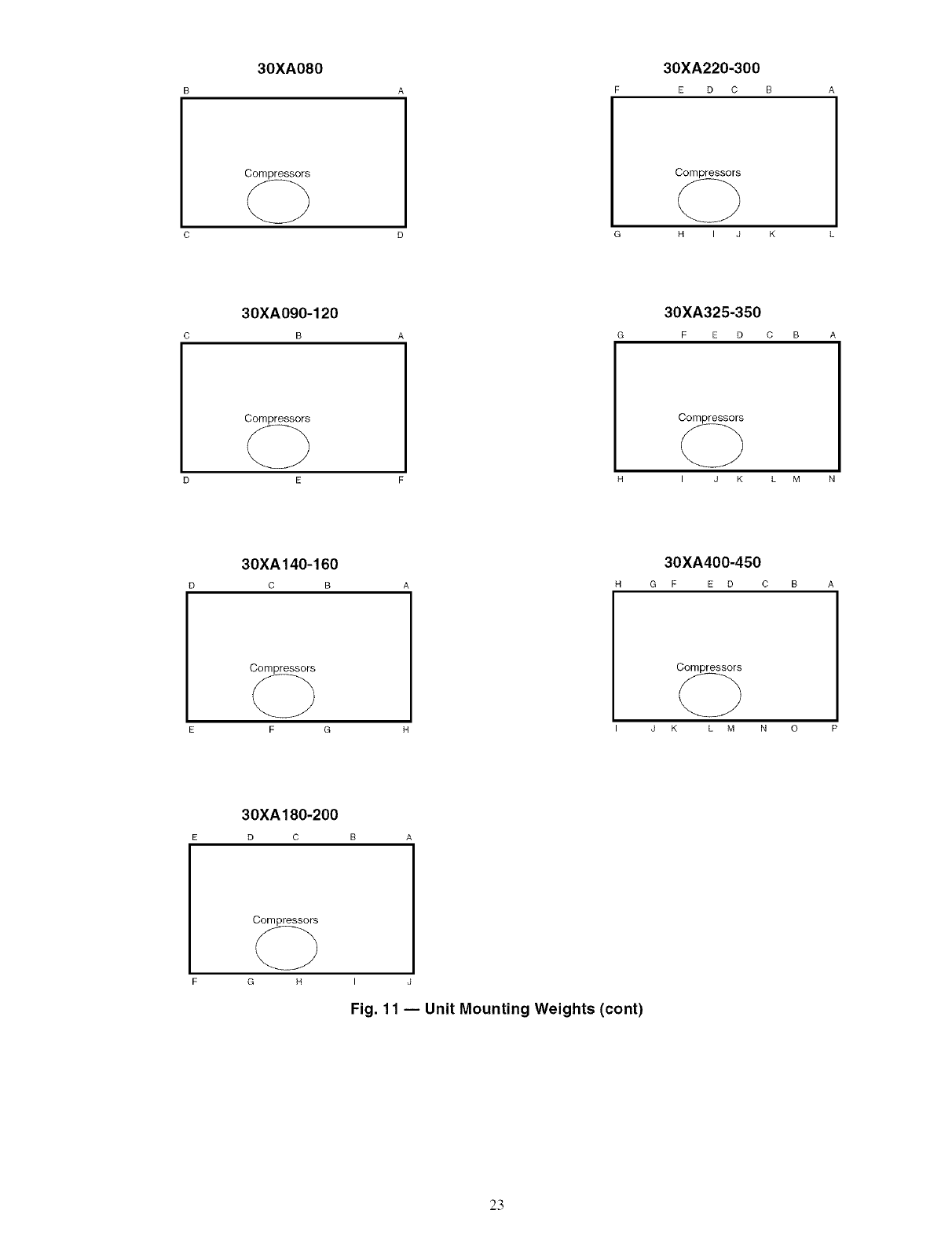
instffllation, refer to unit weight distribution in Fig. 11 to aid in
the proper selection of isolators. The 30XA units can be
mounted directly on spring isolators.
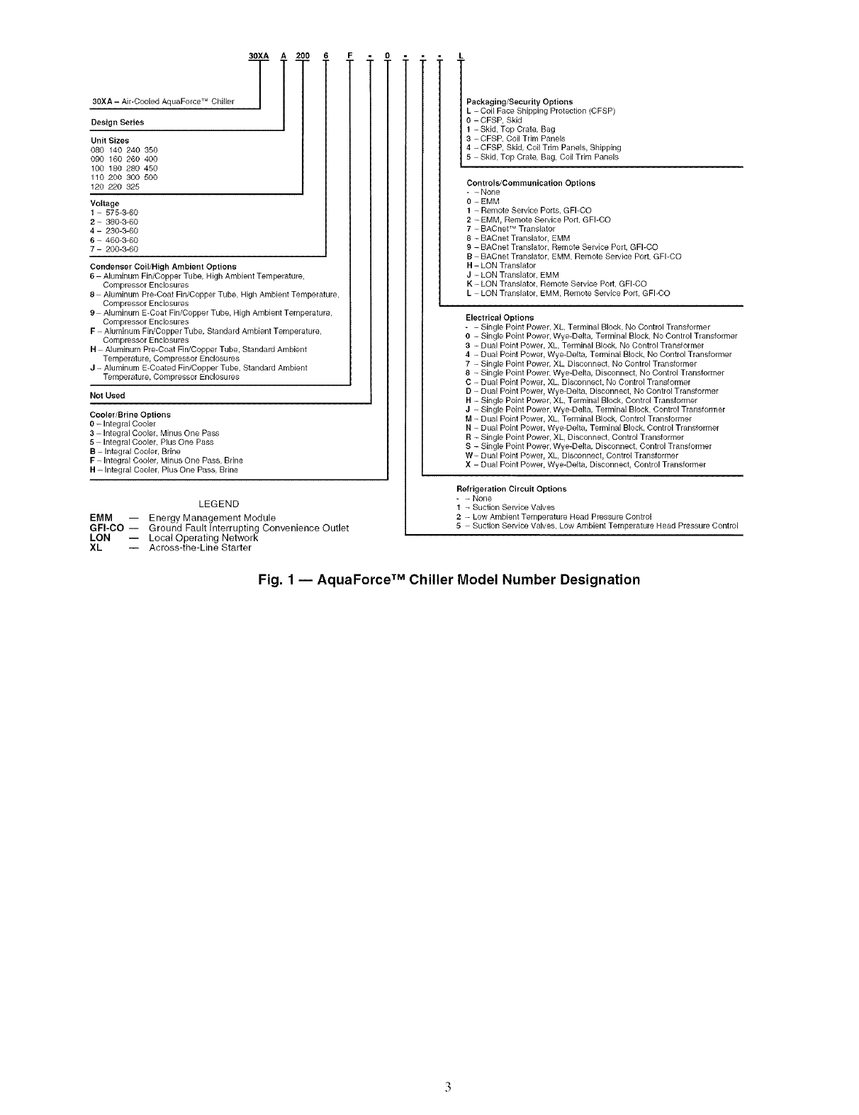
30XA A 200
T
30XA -Air-Cooled AquaForce TM Chiller /
,1
Design Series
Unit Sizes
080 140 240 350
090 160 260 400
f00 180 280 450
110 200 300 500
120 220 325
Voltage
1 - 575-3-60
2- 380-3-60
4-230-3-60
6 - 460-3-60
7 200-3-60
Condenser Coil/High Ambient Options
6 Aluminum Fin/Copper Tube, High Ambient Temperature,
Compressor Enclosures
8 Aluminum Pie-Coat Fin/Coppel Tube, High Ambient Tempelatule,
Compressor Enclosures
9 Alumint.lm E-Coat Fin/Coppel Tube, High Ambient Temperature,
Compressor Enclosures
F Aluminum Fin/Copper Tube, Standard Ambient Temperature,
Compressor Enclosures
H Aluminum Pie-Coat Fin/Coppel Tube, Standard Ambient
Temperature, Compressor Enclosures
J - Aluminum E-Coated Fin/Copper Tube, Standard Ambient
Temperature, Compressor Enclosures
Not Used
Cooler/Brine Options
O- Integral Coolel
3 - Integral Coolel, Minus One Pass
5 Integral Coolel, Plus One Pass
B - Integral Cooler, Brine
F - Integral Cooler, Minus One Pass, Brine
H- Integral Cooler. Plus One Pass. Brine
LEGEND
EMM -- Energy Management Module
GFI-CO -- Ground Fault Interrupting Convenience Outlet
LON -- Local Operating Network
XL -- Across-the-Line Starter
Packaging/Security Options
L- Coil Face Shipping Protection (CFSP)
- CFSP, Skid
- Skid, Top Crate, Bag
- CFSP, Coil Tdm Panels
- CFSP, Skid, Coil Trim Panels, Shipping
Skid, Top Crate, Bag, Coil Trim Panels
Controls/Communication Options
-- None
0- EMM
I - Remote Service Ports, GFI-CO
2 - EMM. Remote Service Port, GFI-CO
7 - BACnet TM Tianslator
8 - BACnet Translator. EMM
9 - BACnet Translator, Remote Service Port, GFI-CO
B - BACnet Translator. EMM, Remote Service Port, GFI-CO
H- LON Tlanslator
J - LON Translator. EMM
K - LON Tianslator, Remote Sewice Port, GFI-CO
L LON Translator, EMM, Remote Service Port, GFI-CO
Electrical Options
- - Single Point Power, XL Terminal Block, No Control Transformer
o - Single Point Power, Wye-Delta, Telminal Block, No Contlol Transformel
3 - Dual Point Power, XL Terminal Block, No Contlol Transformel
4 - Dual Point Poweh Wye-Delta, Terminal Block, No Conhol Tlansformel
7 - Single Point Power, XL Disconnect, No Control Transformer
8 - Single Point Power, Wye-Delta. Disconnect, No Control Tlansformer
C - Dual Point Powel, XL Disconnect, No Contlol Transformer
D - Dual Point Power, Wye-Delta, Disconnect No Contlol Transformel
R - Single Point Power, XL Telminal Block, Control Transformer
J- Single Point Power, Wye-Delta, Telmina] Block, Control Tlansformer
M - Dual Point Power, XL Terminal Block, Control Transformer
R - Dual Point Poweh Wye-Delta, Terminal Block, Contlol Transformer
B - Single Point Power, XL Disconnect, Contlol Transformer
S - Single Point Power, Wye-Delta. Disconnect, Control Tlansformel
W- Dual Point Powel, XL Disconnect, Control Transformer
X Dual Point Power, Wye-Delta, Disconnect Control Transformer
Refrigeration Circuit Options
- - None
I - Suction Service Valves
2 - Low Ambient Temperature Head Pressure Contlol
5 Suction Service Valves, Low Ambient Tempelatule Head Pressure Control
Fig. 1 -- AquaForce TM Chiller Model Number Designation
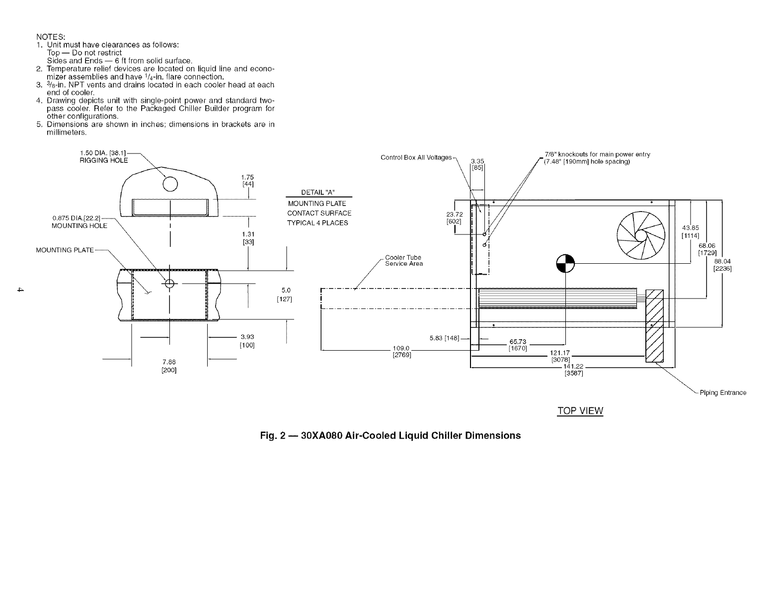
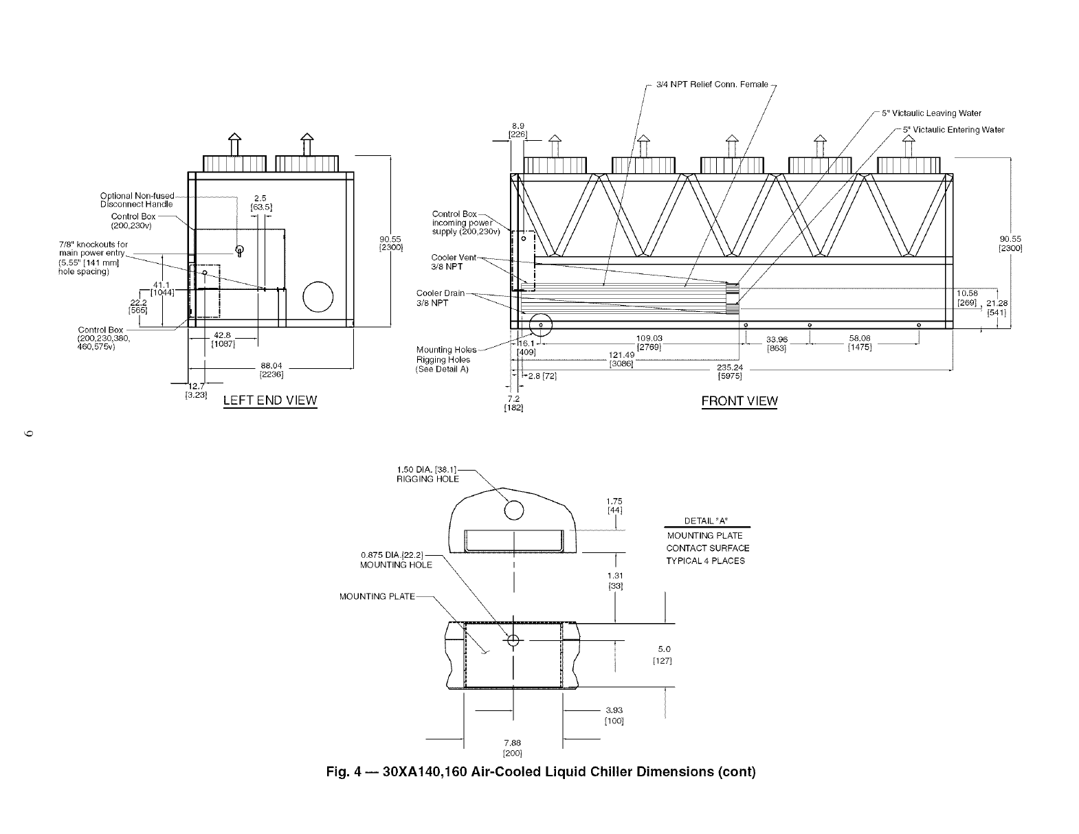
NOTES:
1. Unit must have clearances as follows:
Top -- Do not restrict
Sides and Ends -- 6 ft from solid surface.
2. Temperature relief devices are located on liquid line and econo-
mizer assemblies and have 1/4-in. flare connection.
3. 3/8-in. NPT vents and drains located in each cooler head at each
end of cooler.
4. Drawing depicts unit with single-point power and standard two-
pass cooler. Refer to the Packaged Chiller Builder program for
other configurations.
5. Dimensions are shown in inches; dimensions in brackets are in
millimeters.
4_
1.50 DIA.
RIGGING HOLE
1.75
[4il
0.875 DIA.[22.2]
MOUNTING HOLE _ I I
\ I 1;1
MOUNT'NG PLATE__ _-- "_1 t /
__ .... L........... ,,_
-- -- 3.93
[1oo]
7.88
[200]
DETAIL "A"
MOUNTING PLATE
CONTACT SURFACE
TYPICAL 4 PLACES
5.0
[127]
Control Box All Voltages_ 3.35 /_(_._'8k_koLts] fhOorlemaipnPiOg_r entry
- Cooler Tube I!1 ! _ _ II
I II
I-............................... II
L.................................... /
5.83 [141 '_
I 109.0. _ [1670] ..... //J I
oR
88.04
[2236]
Piping Entrance
TOP VIEW
Fig. 2 -- 30XA080 Air-Cooled Liquid Chiller Dimensions
Optional Non-fused
Control Box
All Voltages_
Display-
Location
(380,460_575v)
41.1
[_[1044 t - ©
88.04
[2236]
LEFT END VIEW
90.55
[2300]
5" Victaulic Leaving Water_
5" Victaulic Entering Water _
I
19.06
68.06
[1729]
88.04
[2236]
RIGHT END VIEW
90.55
[2OO]
8.9
[226]
Control Box All Voltages
3/8 NPT
Cooler Drain _____
3/8 NPT
Mounting Holes_
Rigging Holes
(See Detail A)
[
I
H
[409]
[85]
90.55
--!_ [2i00119.06
[484t
1[2714]
109.03
121.17 [2769] 5" Victaulic
[3078] 141.22 g Water
[3587]
FRONT VIEW
Entering Water
3/4 NPT Relief
Conn. Female
Fig. 2 -- 30XA080 Air-Cooled Liquid Chiller Dimensions (cont)
1.50 DIA. [38.1]_
RIGGING HOLE \
0.875 DIA.[22.2] _
MOUNTING HOLE \ I
MLOA_NTING ___ _\ .........
-- 7.88
[200]
1.75
T
1.31
[331
I 1
5.0
[127I
-- 3.93
[100]
Control Box All Voltages_ \\
DETAIL "A" I
MOUNTING PLATE 23.72
CONTACT SURFACE [6_21
TYPICAL 4 PLACES
1
Cooler Tube
-Service Area _.J
[- ...... ._-/ ..........................
I................iiii.....•
[2769]
3.35 7/8" knockouts for main power entry
/_ (7,48" [190mm] hole spacing)
I
,
B
120.85
[3070] 188.2
[4780]
TOP VIEW
///,
_Piping Entrance
A _
68.06
[1729]
88.04
[2236]
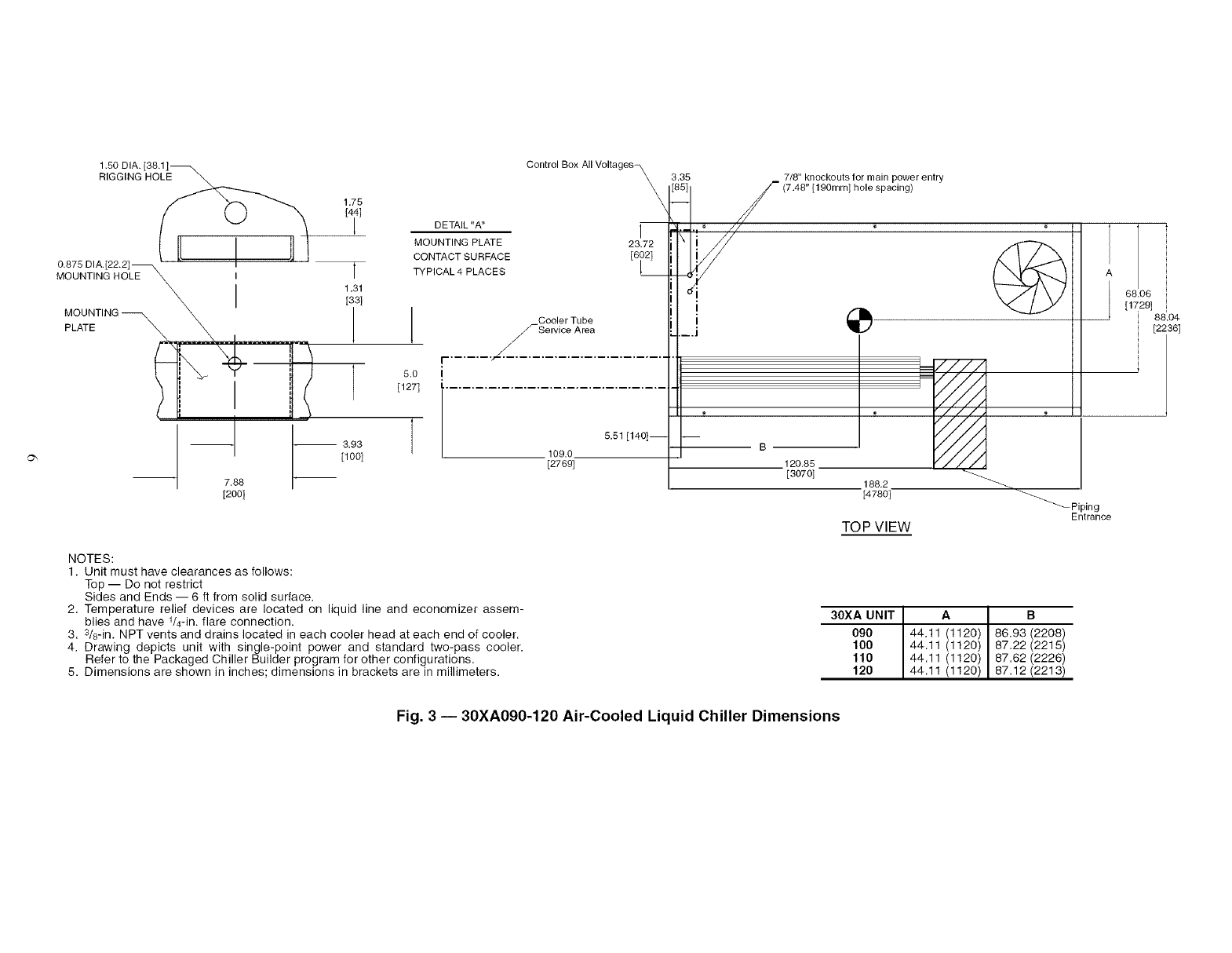
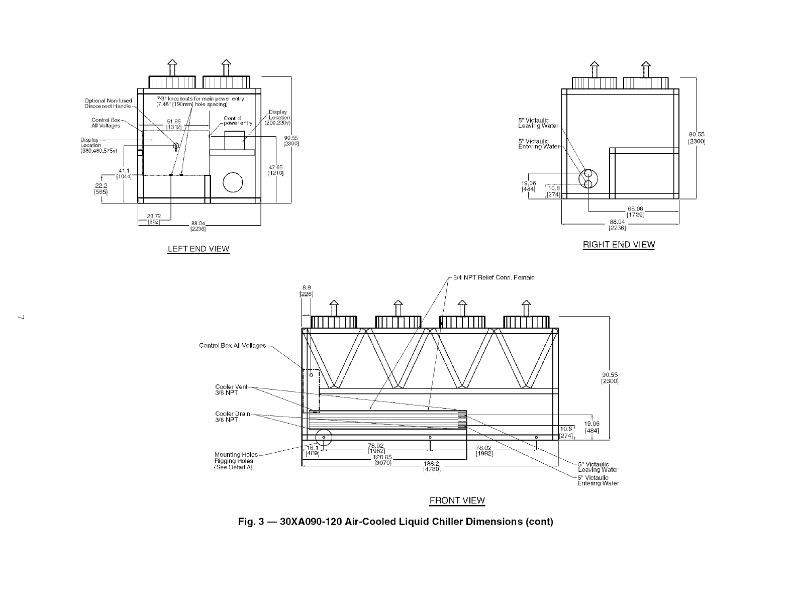
NOTES:
1. Unit must have clearances as follows:
Top -- Do not restrict
Sides and Ends -- 6 ft from solid surface.
2. Temperature relief devices are located on liquid line and economizer assem-
blies and have t/4-in, flare connection.
3. 3/8-in. NPT vents and drains located in each cooler head at each end of cooler.
4. Drawing depicts unit with single-point power and standard two-pass cooler.
Refer to the Packaged Chiller Builder program for other configurations.
5. Dimensions are shown in inches; dimensions in brackets are in millimeters.
30XA UNIT 44.11Al120)( B
090 86,83 (2208)
100 44.11 (1120) 87.22 (2215)
110 44.11 (1120) 87.62 (2226)
120 44.11 (1120) 87.12 (2213)
Fig. 3 -- 30XA090-120 Air-Cooled Liquid Chiller Dimensions
0 ptional Non-fused
Disconnect Handle
Control Box
All Voltages
Displa_
Location
{380,480,575v)
©
88.04
[2236]
LEFT END VIEW
90.55
5" Victaulic
Leaving Water
5" Victaulic
19.05
[17291
L 88.04
[2236]
RIGHT END VIEW
99.55
[2300]
--4
8.9
[226]
Female
Control Box All Voltages
3/8 NPT
3/8 NPT
Mounting
Rigging Holes
(See Detail A) [3070] 188.2
[4780]
[1982]
FRONT VIEW
Fig. 3 -- 30XA090-120 Air-Cooled Liquid Chiller Dimensions (cont)
90.55
] [2i00]
19.06
[4841
5" Victaulic
Leaving Water
5" Victaulic
Entering Water
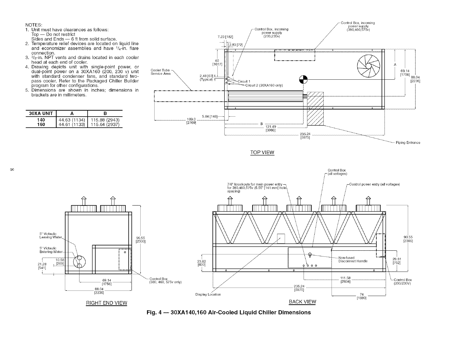
NOTES:
1. Unit must have clearances as fellows:
Top -- Do not restrict
Sides and Ends -- 6 ft from solid surface.
2. Temperature relief devices are located on liquid line
and economizer assemblies and have t/4-in, flare
connection.
3. 8/8-in. NPT vents and drains located in each cooler
head at each end of cooler.
4. Drawing depicts unit with single-point power, or
dual-point power on a 30XA160 (200, 230 v) unit
with standard condenser fans, and standard two-
pass cooler. Refer to the Packaged Chiller Builder
program for other configurations.
5. Dimensions are shown in inches; dimensions in
brackets are in millimeters.
30XA UNIT 44.63A1(134) B
140 115.88 (2943)
160 44.61 (1133) 115.64(2937)
Control Box, incoming
power supply
7.23 [182] /(200,280v) /
__/
_" /F ........... "--'1 "
1/i i
40 i t................. J
[1017] i/
Cooler TubeService Area 2.48 [63] J
(Zyp,cal) _ _ircuit 1
\_ _ O_rou_t 2 (30XA_ 60 on _y)
I- ............. --'_-- ..............
Control Box, incoming
power supply
/ (380,460,575v)
i
i ...............................
5.84 [148]-- --
[2769] 121.49
[3086] 235.24
[5975]
161 8 04
[2286]
_Piping Entrance
TOP VIEW
co
5" Victaulic
Leaving Water.
5" Victaulic
Entering Water
10.58
21.28 , [269]
[541]
i j i
69.14
[1756]
88.04
[2236]
90.55
[2300]
i-o_l_ on,y
RIGHT END VIEW
7/8" knockouts for main
for 380.460.575v 4
spacing)
Control Box
(all voltages)
23.62
[600]
o
J
J
,J
Display Location
f'fi\ /'fi-\ //"Kl'_ / /'r<\
/- i
"--Non-fused -'_
Disconnect Handle
_" o ¢ o
235.24
[5975]
BACK VIEW
111.58
[2834]
74
[188o]
Fig. 4 -- 30XA140,160 Air-Cooled Liquid Chiller Dimensions
90.55
[2800]
Box
(200/230V)
8,9
[226]
73/4NPTReliefConn.Female-
$5" Victaulic Leaving Water
/-5" Victaulic Entering Water
(200,230v)
7/8"knockoutsfor
(5,55" [141 mm]
hole spacing)
41,1
[--[1C
22,2
[565]
1
Control Box
(200,230,380,
460,575v)
90.55
O [2i00t
88.04
[2236]
[3,23] LEFT END VIEW
Control Box
incoming power"-.
supply (200,230v)
3/8 NPT
3/8 NPT
Mounting
Rigging Holes
(See Detail A)
7,2
[182]
109.03
[2769]
121.49
[3086]
33.96
[863]
235.24
[5975]
FRONTVIEW
58.08
[1475]
90.55
[2300]
1.50 DIA.[38.1]_
RIGGING HOLE
0.875 DIA.[22.2]
MOUNTING HOLE \ I
\ I
7,88
[200]
1.75
4i] DETAIL "A"
MOUNTING PLATE
CONTACT SURFACE
l TYPICAL 4 PLACES
1,31
[33]
! 1
5.0
[127]
-- 3,93
[100]
Fig. 4 -- 30XA140,160 Air-Cooled Liquid Chiller Dimensions (cont)
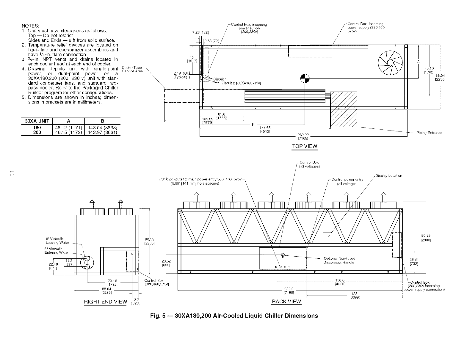
NOTES:
1. Unit must have clearances as follows:
Top -- Do not restrict
Sides and Ends -- 6 ft from solid surface.
2. Temperature relief devices are located on
liquid line and economizer assemblies and
have 1/4-in. flare connection.
3. 3/8-in. NPT vents and drains located in
each cooler head at each end of cooler.
4. Drawing depicts unit with single-point
power, or dual-point power on a
30XA180,200 (200, 230 v) unit with stan-
dard condenser fans, and standard two-
pass cooler. Refer to the Packaged Chiller
Builder program for other configurations.
5. Dimensions are shown in inches; dimen-
sions in brackets are in millimeters.
30XA UNIT A B
180 46.12 (1171) 143.04(3633)
200 46.15 (1172) 142.97 (3631)
Control Box, incoming
power supply
(200,230v)
7.23 [1821
_83 [72] /
I _ ° /
4O
[10171
I
2.48 [63] I1
(Typical) T_
\.r
I
i ..............
Y
Circuit 1
Circuit 2 (30XA160 only)
61.6
[1666] --
[2779] B177.65
[4512]
Control Box, incoming
S power supply (380,460
575v)
/
!.................... J
777777
282.22
[71681
TOP VIEW
I [_°8126[88.04
[2236]
_ Piping Entrance
6" Victaulic
Leaving Water--
6" Victaulic
Entering Water-
22148. , [12183
[5_1I r_
1
7/8" knockouts for main power entry 380, 460, 575v
(5.55" [141 ram[ hole spacing) \
\
7 Control Box
(all voltages)
/DisplayLocation
-Control power entry
(all voltages)
/
I_TT] IIII II_111II
70.16 __
[1782[
88.04
[22361
12.7
RIGHT END VIEW [323[
23.62
[6iO]
Control Box
(380,460,575v)
/"4"\ / "K\_ 4"fi-\ / /"K \/ ! "K \
I
...... OptionalNon-fused
DisconnectHandle
282.2
[7168]
BACK VIEW
158.6
[4028[
122
[3099[
90.55
[2300[
Control Box
(200,230v incoming
] power supply connection)
Fig. 5 -- 30XA180,200 Air-Cooled Liquid Chiller Dimensions
Cooler Vent- -- 3/4 NPT Relief
3/8 NPT Conn. Female
g Water
g Water
Optional Non-fused
Disconnect Handle
Control Box
(200,230v)
7/8'.' knockouts for_
main power entry
(5.55" [141 mm]
hole spacing)
41.1
22171044i
[8_81 /
Control Box _
(200,230,380,
460,575v)
12.7
[323] LEFT END VIEW
©
Control Box,
incoming Power
Supply (200,
230v)
90.55
[2300]
Mountin(
Rigging
(See Detail A)
\1 I
'°_ i i
J.___F 58.08 __. 33.97 78.0___
[489] [1475] 177.65 [863] [1982]
[4512] 28222
[7168]
/%/ /
/\// €,
78.02
[1982]
FRONT VIEW
90.55
[2300]
[571]
1,50 DIA.[3&I
RIGGING HOLE
0.875 DIA.[22.2] _ I
MOUNT,NGHO__ I
MOUNTING PLATE__ ____.__'___..................
7.88
[2OO]
1.75
[4 i] DETAIL "A"
MOUNTING PLATE
CONTACT SURFACE
TYPICAL 4 PLACES
1.31
[33]
I
F 5.0
[127]
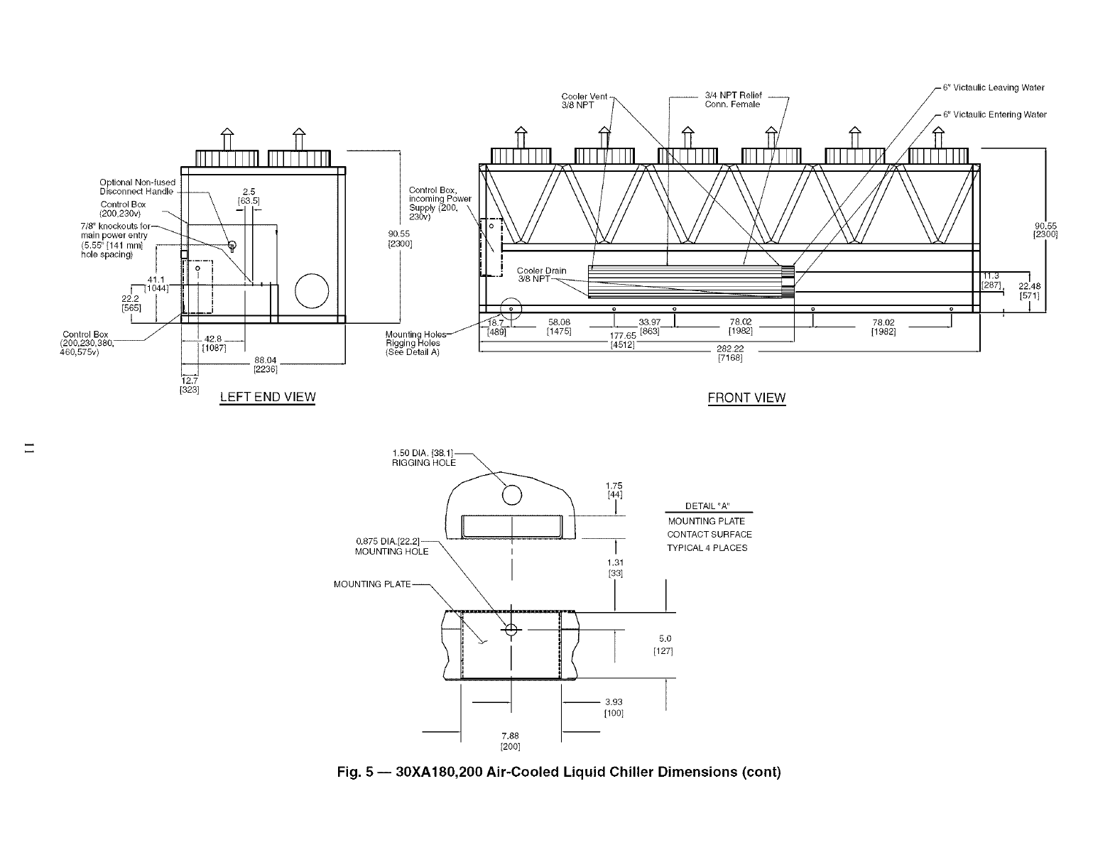
Fig. 5 -- 30XA180,200 Air-Cooled Liquid Chiller Dimensions (cont)
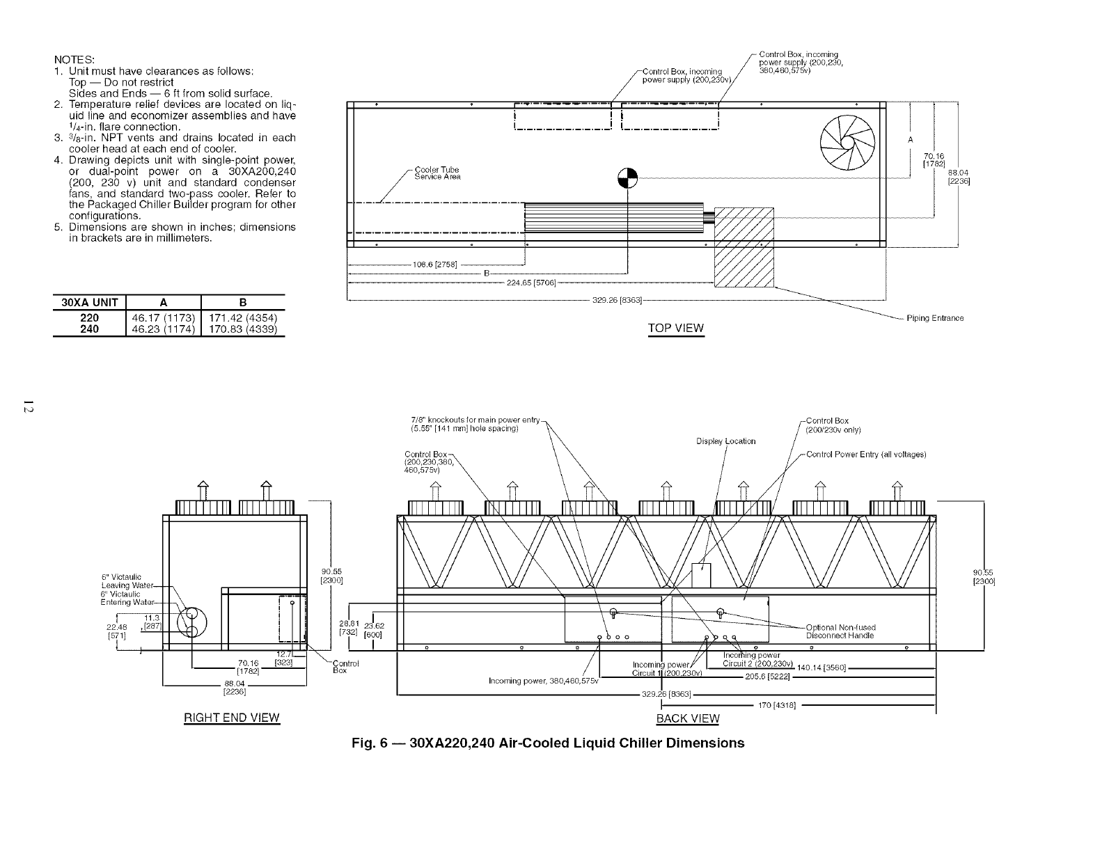
NOTES:
1. Unit must have clearances as follows:
Top -- Do not restrict
Sides and Ends -- 6 ft from solid surface.
2. Temperature relief devices are located on liq-
uid line and economizer assemblies and have
1/4-in. flare connection.
3. 3/6-in. NPT vents and drains located in each
cooler head at each end of cooler.
4. Drawing depicts unit with single-point power,
or dual-point power on a 30XA200,240
(200, 230 v) unit and standard condenser
fans, and standard two-pass cooler. Refer to
the Packaged Chiller Builder program for other
configurations.
5. Dimensions are shown in inches; dimensions
in brackets are in millimeters.
30XA UNIT A B
220 46.17 (1173) 171.42 (4354)
240 46.23 (1174) 170.83 (4339)
.... c°r%T2r
108.6 [2758] B
224.65 [5706]
Control Box, incoming
_ power supply (200,230,
/_Control Box, incoming /380,460,575v)
/p ...... pply (200,23_"
r-'_ ............. ! r-............. "-'f
i ii i @
_o_ o_ [8363]
=/////o/
TOP VIEW
70.16
[1762] 8_
[2; 36]
Piping Entrance
7/8" knockouts for main power entry-
(5.55" [141 mm] hole spacing)
Control Box-
460,575v)
Display Location
=Control Box
(200/230v only)
6" Victaulic
Leavinc
6" Victaulic
Enterin(
f--
22.46
[5
[2236]
RIGHT END VIEW
Box
Incoming power, 380,460.575v Circuit 11(200.230v)
329.26 [8363]
BACK VIEW
140.14[3560]
205.6 [5222]
170 [4318]
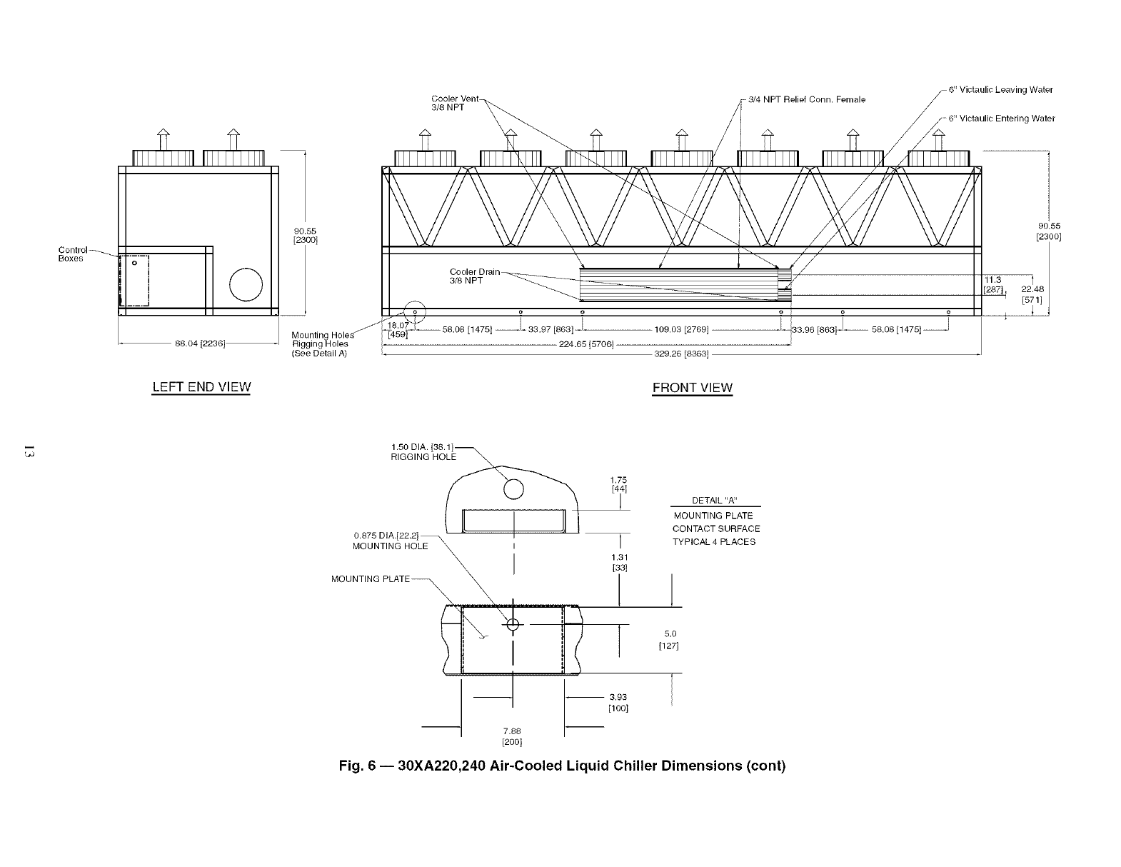
Fig. 6 -- 30XA220,240 Air-Cooled Liquid Chiller Dimensions
9C!55
[2}00]
3/8NPT 3/4NPTReliefConn.Female gWater
.....6"VictaulicEnteringWater
Control_
Boxes ......i
oi©
I
i
.... U
88,04 [2236]-
LEFT END VIEW
90.55
[2300]
(See Detail A)
[1475] - 33,97 [863]- ,
224.65 [5706]
109.03 [2769]
329.26 [8363]
FRONT VIEW
33,96 [863] -- 58.08 [1475]--
90.55
[2300]
1,50 DIA. [38.1]_
RIGGING HOLE \ \
1.75
0.875 DIA.[22.2] \
MOUNTING HOLE _ I
MOU NT'N G PLATE _---__ "_!_-iI-_ [ _t /
--1 -- 3,93
[100]
7.88
[200]
DETAIL "A"
MOUNTING PLATE
CONTACT SURFACE
TYPICAL 4 PLACES
1
5.0
[127]
Fig. 6 -- 30XA220,240 Air-Cooled Liquid Chiller Dimensions (cont)
NOTES:
1, Unit must have clearances as
follows:
Top -- Do not restrict
Sides and Ends -- 6 ft from solid
surface,
2. Temperature relief devices are
located on liquid line and econo-
mizer assemblies and have t/4-in.
flare connection.
3. 3/8-in. NPT vents and drains
located in each cooler head at
each end of cooler.
4. Drawing depicts unit with single-
point power standard condenser
fans and standard two-pass
cooler. Refer to the Packaged
Chiller Builder program for other
configurations.
5. Dimensions are shown in inches;
dimensions in brackets are in
millimeters.
30XA UNIT A B
260 44,22 (1123) 216,16 (5490)
280 44.30 (1125) 215.86 (5483)
300 44.32 (1126) 216.18 (5491)
iCc°o%i?,# wersupp,y
r ................ i °
i i
................... J
........................ ce°°'ie et r ee
J
@
188.35 [4784]
B
304.71 [7740]
_777771
////8 /
\
[2286]
TOP VIEW PipingEntrance
Control Box (all voltages)
7/8" knockouts for main power entry
(5.55" [141 mini hole spacing) \
\
Control Power Entry (all voltages)
8" Victaulic
Leaving Water
\
8" Victaulic
Entering Water\
28!o8
[6ool -- _ r-_
!
I
L.....
-- 71.06 [1805) --
-- 88.04 [2236]
RIGHT END VIEW
90.55
[2300]
C_ontrol Box
\//
'\ i /
\X _ _Optional Non-fused
o o Disconnect Handle
/
199.7 [5072[
Incoming power 245.52 [6236]
(all voltages)
BACK VIEW
55
[2; )O]
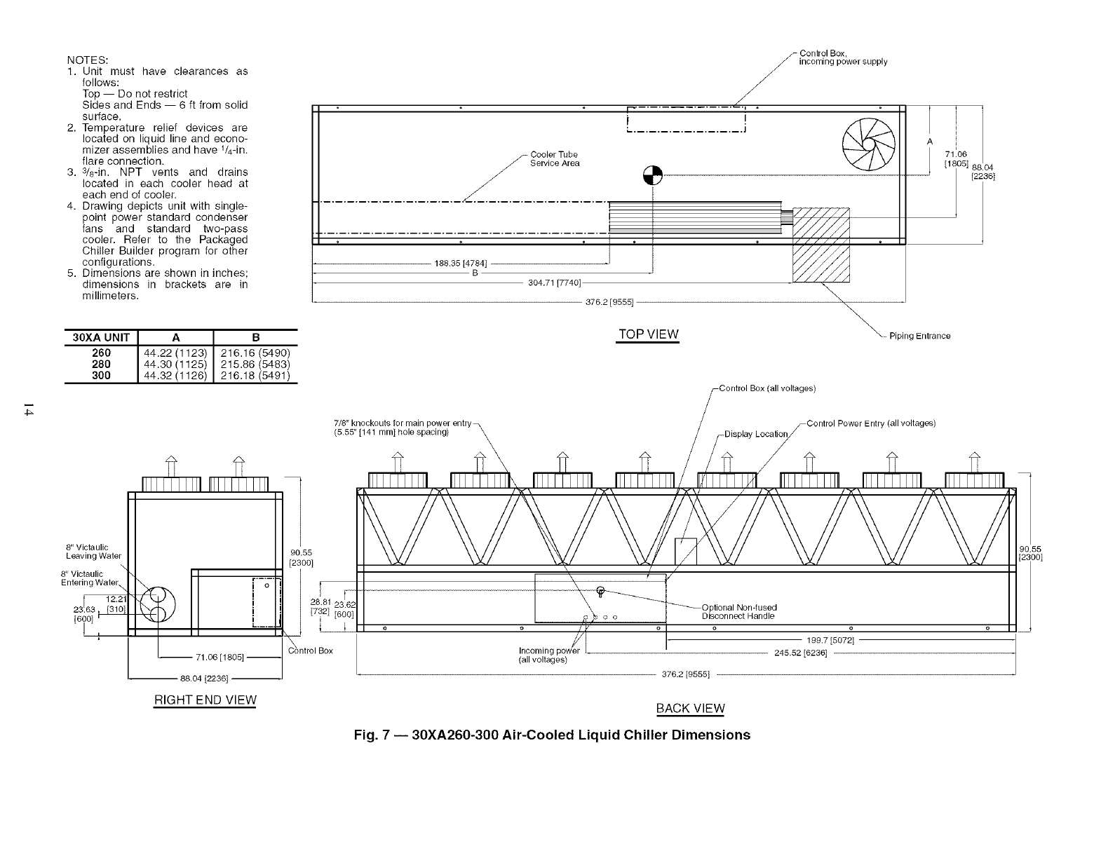
Fig. 7 -- 30XA260-300 Air-Cooled Liquid Chiller Dimensions
3/8 NPT
-3/4 NPT Relief Conn. Female
Victaulic Leaving Water
Victaulic Entering Water
Control Box
/All Voltages
_,q
,
!
i
i
15.77 [401]
88.04 [2236]
90.55
[2300]
,'1
X
Mounting,o, ses78°2 t888I
Rigging Holes
(See Detail A)
_,_ oJ
78,02 [1982] -- 31,96 [812£ -_- 78,02 [1982]
304.71 [7740]
_ _ [9555]
'8,02 [1982]-
90.55
[2300]
L_
LEFT END VIEW FRONT VIEW
1,50 DIA. [38.1]_
RIGGING HOLE _,
0.875 DIA.[22.2]
MOUNTING HOLE _
MOUNTING PLATE_
_._ ...... _____L...........
--1
7.88
[2OO]
1.75
DETAIL "A"
MOUNTING PLATE
CONTACT SURFACE
TYPICAL 4 PLACES
1,31
[33] !
5.0
[127]
-- 3.93 I
[1OO]
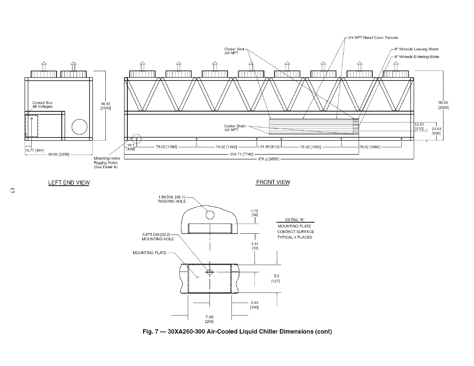
Fig. 7 -- 30XA260-300 Air-Cooled Liquid Chiller Dimensions (cont)
NOTES:
1. Unit must have clearances as follows:
Top -- Do not restrict
Sides and Ends -- 6 ft from solid surface.
2. Temperature relief devices are located on
liquid line and economizer assemblies and
have t/4-in, flare connection.
3. 3/84n. NPT vents and drains located in each
cooler head at each end of cooler.
4. Drawing depicts unit with single-point power,
and dual-point power (380 v), standard con-
denser fans and standard two-pass cooler.
Refer to the Packaged Chiller Builder pro-
gram for other configurations.
5. Dimensions are shown in inches; dimen-
sions in brackets are in millimeters.
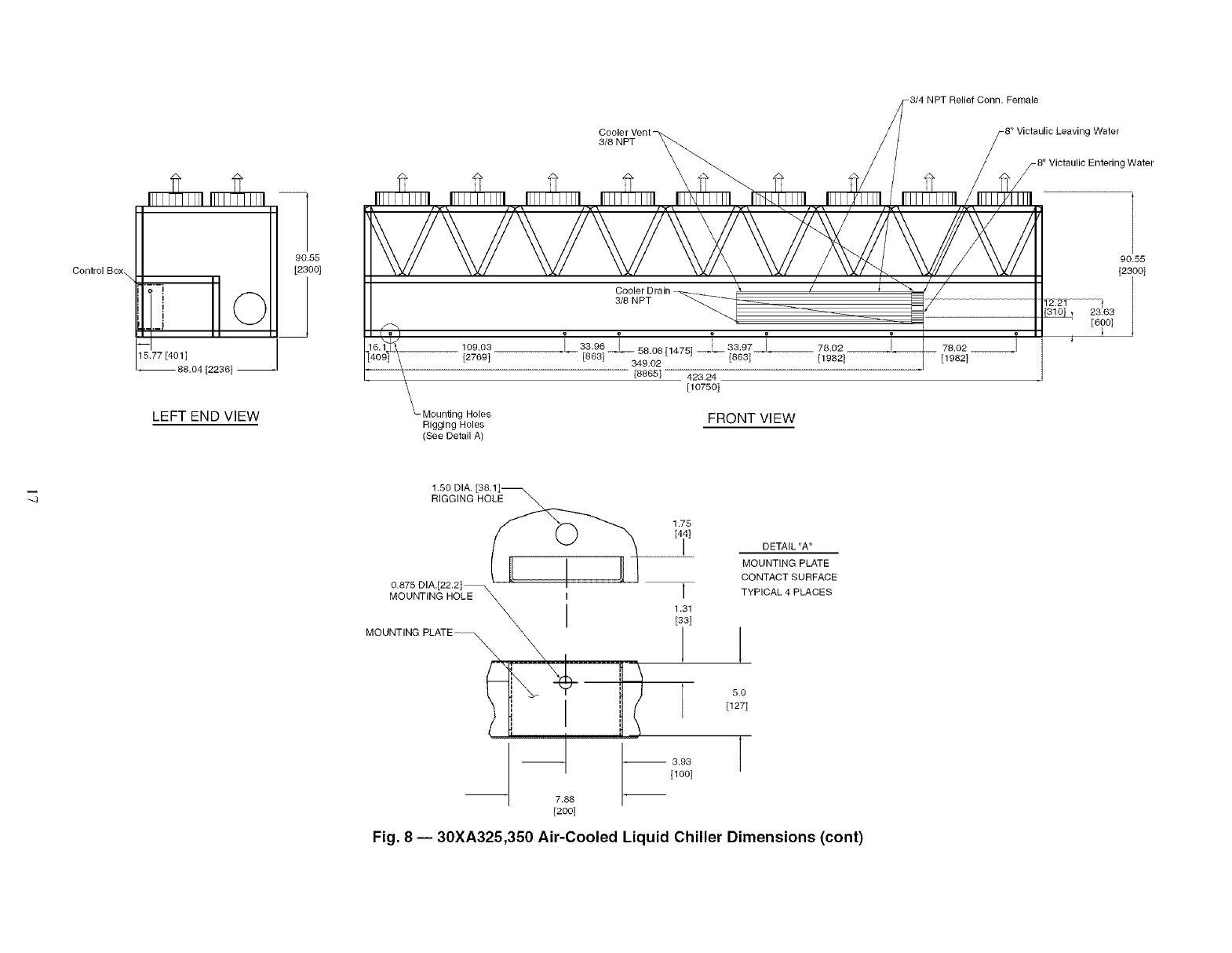
30XA UNIT A B
325 42.92 (1090) 246.16 (6252)
350 42.92 (1090) 246.72 (6267)
........................... -- "--'--"_" -- _C--e°!i_c[e_" reL'-e_............ I _
J
-:...................:::i:::.....:.............
348.02 [8865]
423.24 [107501
TOP VIEW
Control Box, incoming power supply
r .... I " @
_-Piping Entrance
l )81
A
71 06
__ [1_ 88.04
[2i361
8" Victaulic
Leaving Wate[
tVer
23.63 _ [310t
[6oot _
(_5.85'k'1}(_,_k°l_s f]°hrolmeaislpaPc°nWge)re ntrY _. f _0r Di°_plBa(yLocation
_, / / _-Control power entry
------ / \ /"_ "_ / / (\ / "_ _'C t
L 71.06 [1805, _Control Box Circuit 1 all vo_es, d'_ t p t'_A!_ _ -_992'_3_41362187]
-- 88.04 [2236] _ J " " ( g } Circuit 2 (380v only)
423.24 [10750]
RIGHT END VIEW BACK VIEW
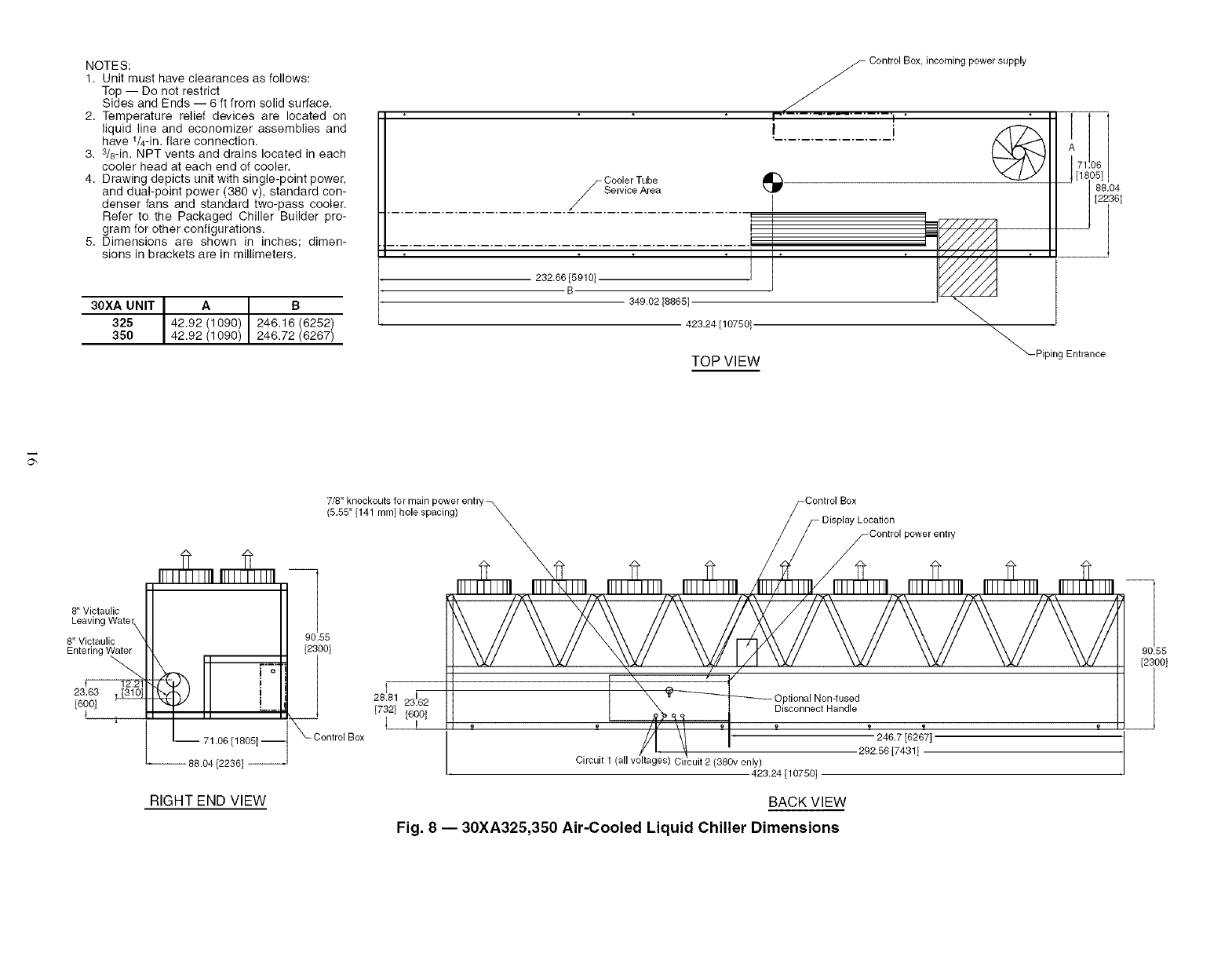
Fig. 8 -- 30XA325,350 Air-Cooled Liquid Chiller Dimensions
_90.55
ControlBox [2300[
_5177[40_]804[2236]-
LEFT END VIEW
Cooler Vent-
3/8 NPT -8 '_Victaulic Leaving Water
8'_Victaulic Entering Water
I =
16._]_9_ 109.03
40 [27691
Cooler Drain
3/8 NPT _----- -_
.L _83691 --L 58.0811475[ i
349.02
[8865] 423.24
[10750]
_- Mounting Holes
Rigging Holes
(See Detail A)
FRONT VIEW
90.55
1 50 DIA
RIGGING HOLE
1.75
I4i, DETAIL "A"
MOUNTING PLATE
CONTACT SURFACE
TYPICAL 4 PLACES
1
5.0
[127]
Fig. 8 -- 30XA325,350 Air-Cooled Liquid Chiller Dimensions (cont)
NOTES:
1, Unit must have clearances as follows:
Top -- Do not restrict
Sides and Ends -- 6 ft from solid surface,
2. Temperature relief devices are located on liq-
uid line and economizer assemblies and have
t/4-in, flare connection.
3. 3/8-in. NPT vents and drains located in each
cooler head at each end of cooler.
4. Drawing depicts unit with dual-point power
standard condenser fans and standard one-
pass cooler. Refer to the Packaged Chiller
Builder program for other configurations.
5. Actual cooler consists of two separate coolers
piped in series at the factory, Piping may be
split for rigging.
6. Dimensions are shown in inches; dimensions
in brackets are in millimeters.
304 1_
[22361 [
ontrol Box #1
- '
Control Box #2_ Piping Entrance-
........... q •
I/
240.69 [6114]
470.22 [11944]
Cooler Tube
7, 02
&_\%_......
_-_-.;,_,_'
_5.a??.[f?s41-
6091
119.0,7 [302, --
TOP VIEW
8" Victaulic
Entering _
© F°
i.._.
-- 72.1 [1831]--
-- 88.04 [2236]-
90,55
[2300]
dControl
Box
7/8" Knockouts for Ckt 1 power_ i-7/8" Knockouts for Ckt 2 power
(5.55" between holes) \ /(5.55" between holes)
\ Optional Non-fused /
_- Disconnect Handles_ /Control Box #2
Control Box #1_ _ /\/l_Display Location
_/\/ // 7 C°ntr°l p°wer entry
_6i0_ , , ,/_ i , i _ /, , __
/r I_-_v_ _:05.7_96_4_.
/] _ 151'5138481
Circuit Jll L A........... 331.58 [8422] Ci c_uit 2
RIGHT END VIEW BACK VIEW
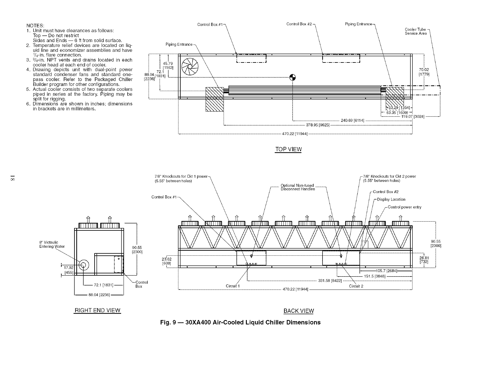
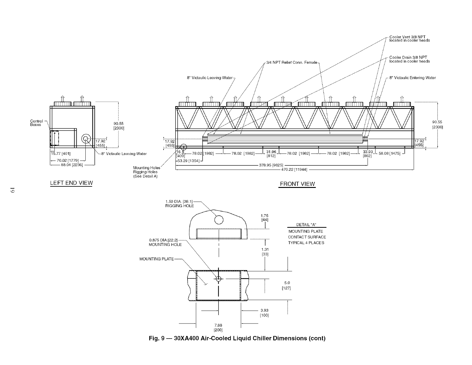
Fig. 9 -- 30XA400 Air-Cooled Liquid Chiller Dimensions
8" Victaulic Leaving Water-
Cooler Vent 3/8 NPT
'/ located incoolerheads
Cooler Drain 3/8 NPT
NPT Relief Conn. Female_ _ located in cooler heads
g Water
Control
Boxes
ii i
b7714°,,I
I'-- 70,02 [1779]
L-- 88.04 [2236] --
LEFT END VIEW
90.55
[2300]
[455],
8" Victaulic Leaving Water
Mounting
Rigging Holes
(See Detail A)
FRONT VIEW
90.55
[2i0O]
1.50 DIA. [38,1]_
RIGGING HOLE
1.75
[4 i]
0.875 DIA.[22.2] 1
MOUNTING HOLE \ I I
_X____._I 1.31
[33]
MOUNTING PLATE p o
[1271
[1001
7.88
[2OO]
Fig. 9 -- 30XA400 Air-Cooled Liquid Chiller Dimensions (cont)
DETAIL "A"
MOUNTING PLATE
CONTACT SURFACE
TYPICAL 4 PLACES
NOTES:
1. Unit must have clearances as follows:
Top -- Do not restrict
Sides and Ends -- 6 ft from solid surface,
2. Temperature relief devices are located on
liquid line and economizer assemblies and
have t/4-in, flare connection.
3. 3/sqn. NPT vents and drains located in
each cooler head at each end of cooler.
4. Drawing depicts unit with dual-point power
standard condenser fans and standard
one-pass cooler. Refer to the Packaged
Chiller Builder program for other configu-
rations,
5. Actual cooler consists of two separate
coolers piped in series at the factory. Pip-
ing may be split for rigging.
6. Dimensions are shown in inches; dimen-
sions in brackets are in millimeters,
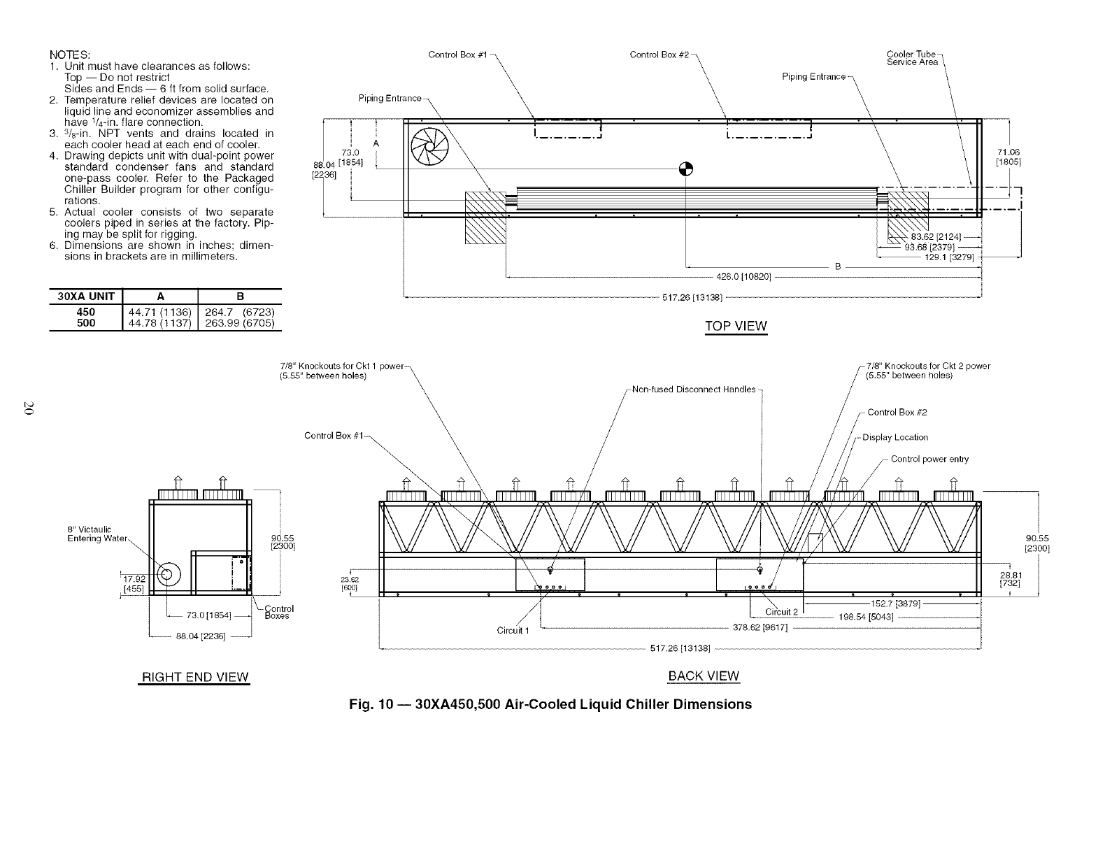
30XA UNIT I A B
450 I44,71 (1136) 264.7 (6723)
500 44.78 (1137) 263.99 (6705)
Control Box #1 _, Control Box #2 _, Cooler Tuber
\\Service Area\
L Piping Entrance ,_ \
Piping Entrance
I......... ._ i ........... ._ \
A
73.0
88.04[1854] 1
[2136]
426.0 [10820]
517.26 [13138]
'_ \ 71.06
[18051
.... ; ........ I
89.62 [21241--
• 129.1 [32791
TOP VIEW
o
8" Victaulic
Entering Water_
' 17.92
[455]
L 73.0 [1854] --
-- 88.04 [2236] --
RIGHT END VIEW
(_.8_'5,K_o_,_o_ts _OrleCs_t1 power_ $(_._'5,K_o_ouls fO_eC_t 2 power
$ Non-fused Disconnect Handles /
_/ / $ Control Box #2
Control Box #1_ _ / / // Display Location
_/ // /Control power entry
N x I_(/ I
23.62
[6_] L90 O
UJ_ '_.. 162._ [38791
_-_°netr°l Circuit 2 198.54 [5043]
Circ • '_7£_0 [a_t 71
90.55
[2300]
28.81
[732]
517.26 [13138]
BACK VIEW
Fig. 10 -- 30XA450,500 Air-Cooled Liquid Chiller Dimensions
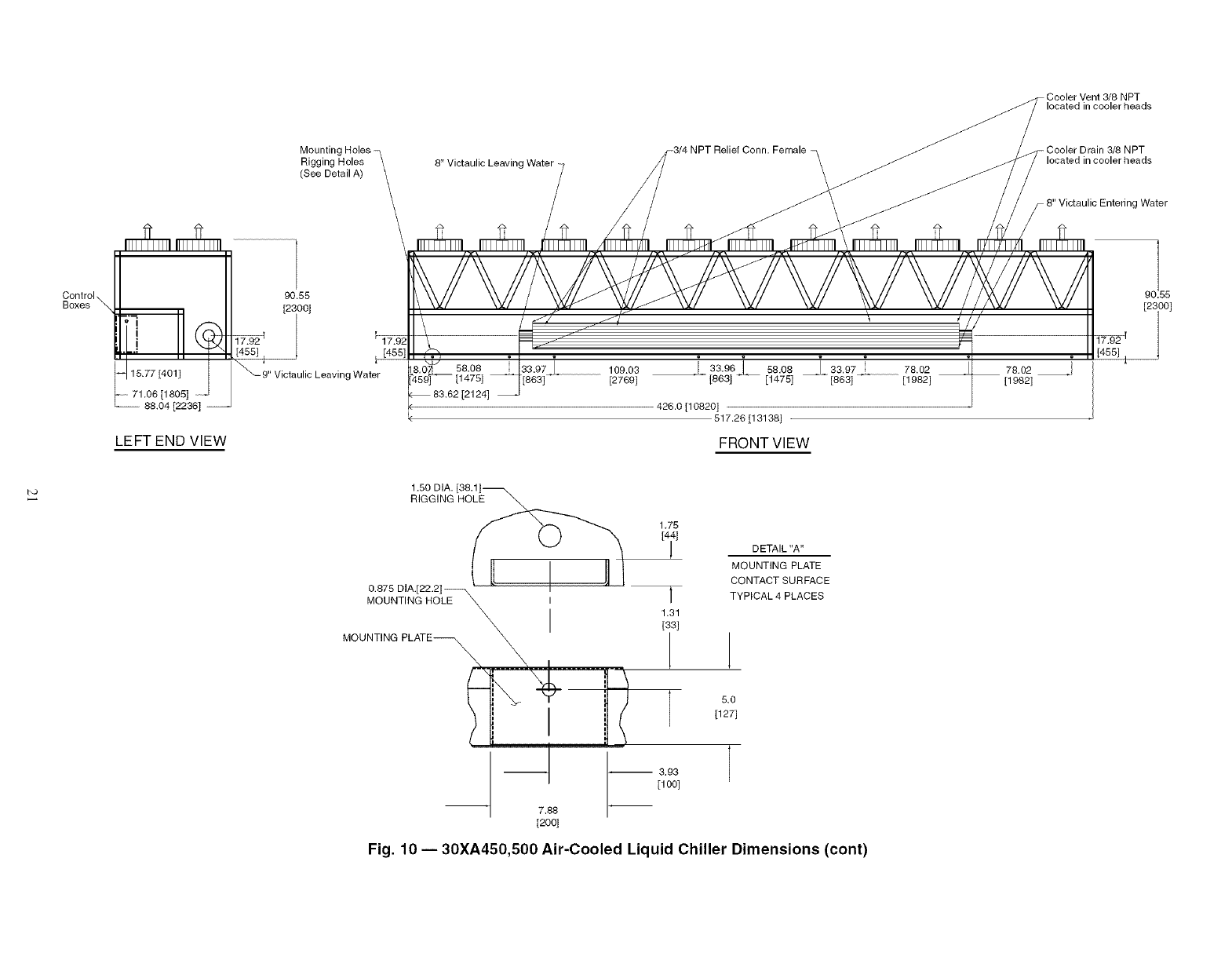
- Cooler Vent 3/8 NPT
located in cooler heads
Mountinc
Rigging Holes
(See Detail A) 8" Victaulic Leaving Water
NPT
located in cooler heads
Victaulic Entering Water
Control \
Boxes \
ii
15.77 [401]
71 06 [1805] i
88,04 [2236] "
LEFT END VIEW
90.55
[2300]
_ 9" Victaulic Leaving Water 58.08
83.62 [2124]
109.03
[2769] h 33.96 [_ 58.08 _J_ 33.97
[863] _ [1475] [863]
78,02
[1982]
78.02
[1982]
426.0 [10820]
517.26 [13138]
FRONT VIEW
90.55
[2i00l
I",3 1.50 DIA.
RIGGING HOLE
1.75
0.875 DIA.[22.2] _ l
MOUNTING HOLE _ I
\ I 1,331,
--1 _ 3.93
[1 O0]
7.88
[200]
DETAIL "A"
MOUNTING PLATE
CONTACT SURFACE
TYPICAL 4 PLACES
5.0
[127]
I
Fig. 10 -- 30XA450,500 Air-Cooled Liquid Chiller Dimensions (cont)
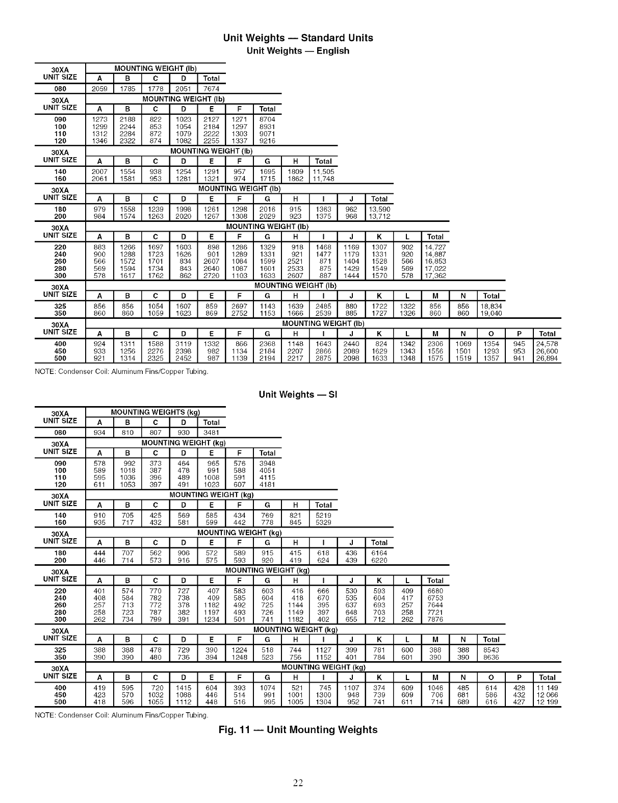
Unit Weights -- Standard Units
Unit Weights -- English
30XA
UNIT SIZE
080
30XA
UNIT SIZE
090
100
110
120
30XA
UNIT SIZE
140
160
30XA
UNIT SIZE
180
2OO
30XA
UNIT SIZE
220
240
260
280
300
30XA
UNIT SIZE
325
35O
30XA
UNIT SIZE
40O
450
5O0
MOUNTING WEIGHT (Ib)
_otal
7674
MOUNTING WEIGHT (Ib)
A I B I c I D I E I F ITota'
1273 I2188 I822 I1023 I2127 I1271 I8704
1299I 2244I 863 I 1064I 2184I 1297I 8931
1312 2284 I872 I 1079I 2222 I1303 I9071
1346 2322 874 1082 2255 1337 9216
MOUNTING WEIGHT (Ib)
A i B i c i o i E iF i G i H ITota,
2007 1554 I938 I1254 I1291 I957 I1695 I1809 111506
2061 1581 953 1281 1321 974 1715 1862 11748
MOUNTING WEIGHT (Ib)
_I_IcloIEIFIGIHI ' IJITota'
979 1558 I1239 I1998 I1261 I1298 I2016 I 916 I 1363 I962 113690
984 1574 1263 2020 1267 1308 2029 923 1375 968 13712
MOUNTING WEIGHT (Ib)
Total
14,727
14,887
16,853
17,022
17,362
MOUNTING WEIGHT (Ib)
_ I _ I c I _ I E I F I G I H I ' I J I K I 'I MI N ITota'
856 866 I1054 I1607 I859 I2697 I1143 I1639 I2485 I880 I1722 I1322 I856 I856 118,834
860 860 1059 1623 869 2752 1153 1666 2539 885 1727 1326 860 860 19,040
MOUNTING WEIGHT (Ib)
A B CD E F G H I J K L M N O P Total
924 1311 1588 3119 1332 866 2368 1148 1643 2440 824 1342 2306 1069 1354 945 24578
933 1256 2276 2398 982 1134 2184 2207 2866 2089 1629 1343 1556 1501 1293 953 26600
921 1314 2325 2452 987 1139 2194 2217 2875 2098 1633 1348 1575 1519 1357 941 26894
NOTE: Condenser Coil; Aluminum Fins/Copper Tubing.
Unit Weights -- SI
30XA
UNIT SIZE
O8O
30XA
UNIT SIZE
090
100
110
120
30XA
UNIT SIZE
140
160
30XA
UNIT SIZE
180
2OO
30XA
UNIT SIZE
220
24O
260
28O
30O
30XA
UNIT SIZE
325
35O
30XA
UNIT SIZE
40O
45O
5OO
MOUNTING WEIGHTS (kg)
_otal
3481
MOUNTING WEIGHT (kg)
A B C D E F Total
578 992 373 464 965 576 3948
589 1018 387 478 991 588 4061
595 1036 396 489 1008 591 4116
611 1053 397 491 1023 607 4181
MOUNTING WEIGHT (kg)
A i _ i c i o i E i F i G i H iTot°,
910 705 I425 I569 I686 I434 I769 I821 16219
935 717 432 581 599 442 778 846 5329
MOUNTING WEIGHT (kg)
_I_IcloIEIFIGIHI ' IJI
444 707 I562 I906 I572 I589 I915 I415 I618 I436 I
446 714 573 916 575 593 920 419 624 439
MOUNTING WEIGHT (kg)
Total
6164
6220
A B CD E F G H I J K L Total
401 574 770 727 407 583 603 416 666 530 693 409 6680
408 584 782 738 409 585 604 418 670 535 604 417 6753
257 713 772 378 1182 492 725 1144 395 637 693 257 7644
258 723 787 382 1197 493 726 1149 397 648 703 258 7721
262 734 799 391 1234 501 741 1182 402 655 712 262 7876
MOUNTING WEIGHT (kg)
A I B I c I o I E I F I G I H I ' I J I K I ' I M I N ITota'
388 388 I478 I729 I390 112241 618 I 744 111271 399 I 781 I 600 I 388 I 388 18648
390 390 480 736 394 1248 523 756 1152 401 784 601 390 390 8636
MOUNTING WEIGHT (kg)
I A BC D E F G H I J K L MN O PTotal
419 595 720 1415 604 393 1074 521 745 1107 374 609 1046 485 614 428 11 149
423 570 1032 1088 446 514 991 1001 1300 948 739 609 706 681 586 432 12 066
418 596 1055 1112 448 516 995 1005 1304 952 741 611 714 689 616 427 12 199
NOTE: Condenser Coil: Aluminum Fins/Copper Tubing.
Fig. 11 -- Unit Mounting Weights
22
30XA080 30XA220-300
EDC B
Compressors Compressors
G H I J K
30XA090-120
B
30XA325-350
F E D C B
Compressors Compressors
I J K L M
30XA140-160
c B
Compressors
FG
30XA400-450
G F E D C B
Compressors
J K L M N 0 P
30XA180-200
E D C B
Compressors
I
Fig. 11 -- Unit Mounting Weights (cont)
23
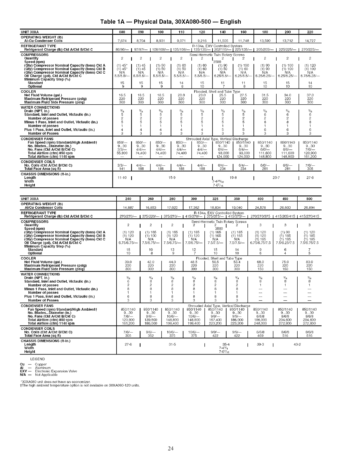
Table 1A- Physical Data, 30XA080-500- English
UNIT 30XA
OPERATING WEIGHT (Ib)
AI-Cu Condenser Coils
REFRIGERANT TYPE
Refrigerant Charge (Ib) Ckt A/Ckt B/Ckt C
COMPRESSORS
Quantity
Speed (rpm)
(Qty) Compressor Nominal Capacity (tons) Ckt A
(Qty) Compressor Nominal Capacity (tons) Ckt B
(Oty) Compressor Nominal Capacity (tons) Ckt C
Oil Charge (gal), Ckt A/Ckt B/Ckt C
Minimum Capacity Step (%)
Standard
Optional
COOLER
Net Fluid Volume (gal.)
Maximum Refrigerant Pressure (pslg)
Maximum Fluid Side Pressure (psig)
WATER CONNECTIONS
Drain (NPT, In.)
Standard, Inlet and Outlet, Vlctaullc (in.)
Number of passes
Minus 1 Pass, Inlet and Outlet, Victaullc (in.)
Number of passes
Plus 1 Pass, Inlet and Outlet, Victaullc (in.)
Number of Passes
CONDENSER FANS
Fan Speed (rpm) Standard/High Ambientt
No. Blades...Diameter (in.)
No. Fans (Ckt A/Ckt B/Ckt C)
Total Airflow(cfm) 850 rpm
080 090 100 110 120 140 160 180 200 220
7,674 8,704 8,931 9,071 9,216 11,505 11,748 13,590 13,712 14,727
R-134a, EXV Controlled System
66/66/-I97/97/-11°6/1°6/-I135/1°6/-I135/135/-12°22115/-I225/135/-I 205/205/-I 225/225/-I 270/225/-
Semi-HermeticTwin Rotary Screws
2I2 I 2 I 2 I 2 135002 I 2 I 2 I 2 I 2
(1)45" I(1)45 (1)50 (1)60 (1)60 I(1)90 (1)100 (1)90 (1) 100 (1)120
(1) 45* I (1) 45 (1) 50 (1) 50 (1) 60 I(1) 50 I(1) 60 I(1) e0 I (1) 100 I (1)100
N/A N/A N/A N/A N/A
N/A N/A N/A N/A N/A 7 8 10 1O 10
5.5/5.5/-- 5.5/5.5/-- 5.5/5.5/-- 5.5/5.5/-- 5.5/5.5/-- 6.25/5.5/-- 6.25/5.5/-- 6.25/6.25/-- 6.25/6.25/-- 6.75/6.25/--
15 15 15 14 15 11 11 15 15 14
9 9 9 8 10
Flooded, Shell and Tube Type
16.5 I 16.5 18.5 20.0 23.0 I 25.5 27.5 31.5 34.0 37.0
220 I 220 220 220 220 I 220 220 220 220 220300 300 300 300 300 300 300 300 300 300
3/s 3/8 3/s 3/s 3/s I3/s 3/8 3/s 3/s 3/s
5 5 5 5 5 I 5 5 6 6 6
2 2 2 2 2 2 2 2 2 2
5 5 5 5 5 5 5 6 8 6
1 1 1 1 1 1 1 1 1 1
4 4 4 4 4 5 5 6 6 6
33 3 3333 3 3 3
Shrouded Axial Type, Vertical Discharge
650/-- I 650/-- 850/-- 650/-- 650/-- I 650/1 140 850/1 140 850/1140 850/1 140 650/1 140
9...30 I 9...30 9...30 9...30 9...30 I 9...30 9...30 9...30 9...30 9...30
3/3/-- 4/4/-- 4/4/-- 4/4/-- 4/4/-- 6/4/-- 6/4/-- 6/6/-- 6/6/-- 7/6/--
55,800 74,400 74,400 74,400 74,400 93,000 93,000 111,600 111,600 120,900
..... 124,000 124,000 148,800 148,800 161,200
Total Airflow !cfm! 1140 rpm
CONDENSER COILS
No. Coils (Ckt A/Ckt R/Ckt C) 3/3/-- 4148/_ 4_48/_ 4_ 4_ 6/43/_- 6/43/_- 6/6/-- 6_6_- 7/6/--
Tota,FaceArea(sg.) 141I I I I I I I 281I I 3O5
CHASSIS DIMENSIONS (ft-ln.)
Length 11-10 I15-9 I19-8 I23-7 I27-6
Width 7=425/3_
Height 7-67/_6
UNIT 30XA
OPERATING WEIGHT (Ib)
AI/Cu Condenser Coils
REFRIGERANT TYPE
Refrigerant Charge (Ib) Ckt A/Ckt B/Ckt C
COMPRESSORS
Quantity
Speed (rpm)
(Qty) Compressor Nominal Capacity (tons) Ckt A
(Qty) Compressor Nominal Capacity (tons) Ckt B
(Oty) Compressor Nominal Capacity (tons) Ckt C
OII Charge (gal), Ckt A/Ckt B/Ckt C
Minimum Capacity Step (%)
Standard
Optional
COOLER
Net Fluid Volume (gal.)
Maximum Refrigerant Pressure (pslg)
Maximum Fluid Side Pressure (pslg)
WATER CONNECTIONS
Drain (NPT, In.)
Standard, Inlet and Outlet, Vlctaullc (in.)
Number of passes
Minus 1 Pass, Inlet and Outlet, Vlctaullc (in.)
Number of passes
Plus 1 Pass, Inlet and Outlet, Vlctaullc (in.)
Number of Passes
CONDENSER FANS
Fan Speed (rpm) Standard/High Amblentt
No. Blades...Dlameter (in.)
No. Fans (Ckt A/Ckt B/Ckt C)
240 260 280 300 325 350 400 450 500
14,887 16,853 17,022 17,362 18,834 19,040 24,578 26,600 26,894
R-134a, EXV Controlled System
27_270/-- _ 375/22_-- I 375/27_-- I 415/270/-- I 375_7_-- I 415/37_-- I 27_27_375 I 41_205_15 I 41_270/415
Semi-Hermetic Twin Rotary Screws
2I2 I 2 I 2 I 2 I 2 I 3
3500
(1) 120 (1) 165 (1) 165 (1) 185 (1) 165 (1) 185 (1) 120
(1) 120 I (1) 100 I (1) 120 I (1) 120 I (1) 165 (1) 165 (1) 120
N/A N/A N/A N/A N/A N/A (1)165
6.75/6.75/-- 7.5/6.75/-- 7.5/6.75/-- 7.5/6.75/-- 7.5/7.5/-- 7.5/7.5/-- 6.75/6.75/7.5
15 10 13 12 15 14
10 8 9 7 10 10
Flooded, ShellandTubeType
39.0 I 42.0 44.0 48.5 50.5 53.4 68.0 75.0 83.0
220 I 220 220 220 220 220 220 220 220300 300 300 300 300 300 150 150 150
3& I 3/s 3/s 3/s 3/s 3/s 3/s
6 I 6 8 8 6 6 8
2 2 2 2 2 2 1
8 6 8 8 6 6 --
1 1 1 1 1 1 --
6 6 8 8 6 6 --
3 3 33 3 3 --
Shrouded Axial Type, Vertical Discharge
I 850/1140 850/1140 850/1140 850/1140 850/1140 650/1140
9/6/-- 10/6/-- 10/6/-- 9/9/-- 9/9/-- 6/6/8
33
(1)90 (1) 120
(1) 185 (1) 185
(1) 185 (1) 185
7.5/6.25/7.5 7.5/6.75/7.5
6 7
4 5
%
6
1
850/1140
¾
8
1
650/1140
9...30
8/6/8
204,600
272,800
850/1140
7/6/-- 911130
6/6/8
204,600
272,800
Total Airflow (cfm) 850 rpm
Total Airflow (cfm) 1140 rpm
CONDENSER COILS
No. Coils (Ckt A/Ckt B/Ckt C)
Total Face Area (sq ft)
CHASSIS DIMENSIONS (ft-ln.)
Length
Width
Height
9...30 9...30 9...30 9...30 9...30 9...30 9...30
120,900 139,500 148,600 148,600 167,400 186,000 186,000
161,200 186,000 198,400 196,400 223,200 223,200 248,000
i 9/6/-i 10/6/-i 10/6/-i 9/9/-i 9/9/-1352375 375 422 4226/6/8469I 6/6/6516I 6/6/8516
27-6 I31-5 I 35-4 I 39-3 I 43-2
743/4
7=67/16
LEGEND
Cu -- Copper
AI -- Aluminum
EXV-- Electronic Expansion Valve
N/A -- Not Applicable
*30XA080 unit does not have an economizer.
tThe high ambient temperature option is not available on 30XA080-120 units.
24
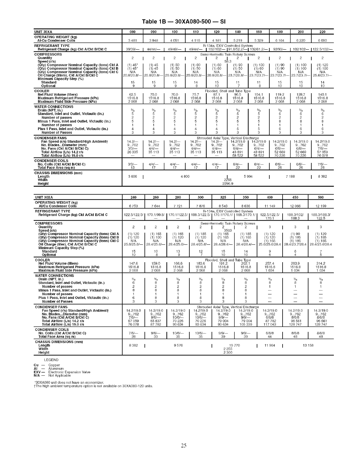
Table 1B -- 30XA080-500 -- SI
UNIT 3OXA
OPERATING WEIGHT (kg)
AI-Cu Condenser Coils
REFRIGERANT TYPE
Refrigerant Charge (kg) Ckt A/Ckt B/Ckt C
COMPRESSORS
QuanUty
Speed (r/s)
(Qty) Compressor Nominal Capacity (tons) Ckt A
(Qty) Compressor Nominal Capacity (tons) Ckt B
(Oty) Compressor Nominal Capacity (tons) Ckt C
Oil Charge (liters), Ckt A/Ckt B/Ckt C
Minimum Capacity Step (%)
Standard
OpUonal
COOLER
Net Fluid Volume (liters)
Maximum Refrigerant Pressure (kPa)
Maximum Fluid Side Pressure (kPa)
WATER CONNECTIONS
Drain (NPT, In.)
Standard, Inlet and Outlet, Victaullc (in.)
Number of passes
Minus 1 Pass, Inlet and Outlet, Victaullc (in.)
Number of passes
Plus 1 Pass, Inlet and Outlet, Victaulic (in.)
Number of Passes
CONDENSER FANS
Fan Speed (r/s) Standard/High Ambientt
No. Blades._Diameter (ram)
No. Fans (Ckt A/Ckt B/Ckt C)
Total Airflow (L/s) 14.2 r/s
Total Airflow IL/s! 19.0 r/s
CONDENSER COILS
No. Coils (Ckt A/Ckt B/Ckt C)
Total Face Area (sg m)
CHASSIS DIMENSIONS (ram)
Length
Width
Height
080 090 100 110 120 140 160 160 200 220
3 481 3 948 4 051 4 115 4 181 5 219 5 329 6 164 6 220 6 660
R-1 64a, EXV Controlled System
39/39/-I 44/44/- 149/49/- 149/44/-1102/10"2/-191.6/62.2/-1102/61.2/- 193/93/- 1102/102-1122.5/102/--
SembHermetic Twin Rotary Screws
2I2I2I2I2 5_.3v 2 I2I2I2I2
(1) 45" (1)45 (1)50 (1)60 (1)60 (1)90 (1) 100 (1)90 (1) 100 (1) 120
(1)45" I (1)45 I (1)50 I (1)50 I (1)60 I (1)50 I (1)60 I (1)90 I (1)100 I (1)100
N/A N/A N/A N/A N/A N/A N/A N/A N/A N/A
20.6/20.8/-- 20.8/20.6/-- 20.6/20.6/-- 20.6/20.8/-- 20.8/20.6/-- 23.7/20.8/-- 23.7/23.7/-- 23.7/23.7/-- 23.7/23.7/-- 26.6/23.7/--
15 15 15 14 15 11 11 15 15 14
9 v v 6 10 7 8 10 10 10
Flooded, Shell and Tube Type
5 5
2 2
5 5
1 1
4 4
3 3
5
2
5
1
4
3
14.2/-- 14.2/-- 14.2/--
9...762 9_.762 9...762
3/3/-- 4/4/-- 4/4/--
26335 35113 35113
Shrouded Axial Type, Vertical Discharge
14.2/-- I 14.2/-- 14.2/19.0 I 14.2/19.0 I 14.2/19.0 14.2/19.0
9...762 9...762 9...762 9...762 9...762 9...762
4/4/-- 4/4/-- 6/4/-- 6/4/-- 6/6/-- 6/6/--
35113 35113 43891 43891 52669 52669
-- -- 58 522 58 522 70 226 70 226
140.1
1516.8
2 068
6 6
2 2
6 8
1 1
6 6
3 3
14.2/19.0
9...762
7/_--
57 059
76 078
3/3/-- 4/_-- 4/_-- 4/4/-- 4/_-- 6/4/-- 6/4/-- 6/6/-- 6/6/-- 7/6/--
13I I I 17 I I 22 I 22I 26 I 26 I 26
3 606 I4 800 2455 5 994 I7 188 I8 382
2296.9
UNIT 30XA
OPERATING WEIGHT (kg)
AI/Cu Condenser Coils
REFRIGERANT TYPE
Refrigerant Charge (kg) Ckt A/Ckt B/Ckt C
COMPRESSORS
OuanUty
Speed (r/s)
(Qty) Compressor Nominal Capacity (tons) Ckt A
(Qty) Compressor Nominal Capacity (tons) Ckt B
(Qty) Compressor Nominal Capacity (tons) Ckt C
OII Charge (liter), Ckt A/Ckt B/Ckt C
Minimum Capacity Step (%)
Standard
OpUonal
COOLER
Net Fluid Volume (liters)
Maximum Refrigerant Pressure (kPa)
Maximum Fluid Side Pressure (kPa)
WATER CONNECTIONS
Drain (NPT, In.)
Standard, Inlet and Outlet, Vlctaullc (in.)
Number of passes
Minus 1 Pass, Inlet and Outlet, Vlctaullc (in.)
Number of passes
Plus 1 Pass, Inlet and Outlet, Vlctaullc (in.)
Number of Passes
CONDENSER FANS
Fan Speed (r/s) Standard/High Amblentt
No. Blades...Dlameter (mm)
No. Fans (Ckt A/Ckt B/Ckt C)
Total Airflow (L/s) 14.2 r/s
Total Airflow (L/s) 19.0 r/s
CONDENSER COILS
No. Coils (Ckt A/Ckt B/Ckt C)
Total Face Area (sq m)
CHASSIS DIMENSIONS (ram)
Length
Width
Height
240 260 280 300 325 350 400 I450 500
6753 7644 7721 7676 8543 6636 11149 I 12066 12199
R-134a, EXV Controlled System
122.6/122.6/1170.1/99.6/1170.1/122.6/I_ 188.3/122.6/1170.1/170.1/1168.3/170.1/1122.5/122.5/170.11168.31122. 5166.3/102/186.3/188.3/
SembHermetic Twin Rotary Screws
2I2I2I2I23500I 2 I 3 I3 I 3
(1) 120 (1) 165 (1) 165 (1) 185 (1) 165 (1) 185 (1) 120 (1) 90 (1) 120
(1) 120 I (1) 100 I (1) 120 I (1) 120 (1) 165 (1) 165 (1) 120 (1) 185 (1) 185
N/A N/A N/A N/A IN/A IN/A I(1) 166 I(1)166 I(1)185
25.6/26.6/--10 26.4/25.6/--8 26.4/26.6/--9 28.4/26.6/--_ 26.4/28.4/--10 28.4/28.4/--10 26.6/25.6/28.46 28.4/23.7/28.44 28.4/25.6/28.45
15 10 13 12 15 14 9 6 7
Flooded, Shell and Tube ] 257.4 I 283.9 314.2
1516.8 I 1516.8 1516.81034 1034 1034
3/s 3/s 3/s 3/s 3/s 3/s 3/8 I3/s 3/8
6 6 8 8 8 8 8 I 8 8
2 2 2 2 2 2 1 1 1
6 6 8 8 8 8 -- -- --
1 1 1 1 1 1 -- -- --
6 6 8 8 8 8 -- -- --
33333 3 -- -- --
Shrouded Axial Type, Vertical Discharge
14.2/19.0 14.2/19.0 14.2/19.0 14.2/19.0 14.2/19.0 14.2/19.0 14.2/19.0 I 14.2/19.0 14.2/19.0
9...762 9...762 9...762 9...762 9...762 9...762 9...762 I 9...762 9...762
7/6/-- 9/6/-- 10/6/-- 10/6/-- 9/9/-- 9/9/-- 6/6/8 8/6/8 8/6/8
57059 65837 70226 70226 79004 79004 87782 96561 96561
76078 87762 93634 93634 93634 105339 117043 128747 128747
7/6/-19/6/-11°/6/-11°/6/-19/9/-19/9/-I26 33 36 36 39 39 6/6/616/6/616/6/844 48 46
8362 I 9576 I 10770 I 11964 I13168
2 255
2 300
LEGEND
CU -- Copper
AI -- Aluminum
EXV-- Electronic Expansion Valve
N/A -- Not Applicable
*30XA080 unit does not have an economizer.
tThe high ambient temperature option is not available on 30XA080-120 units.
25
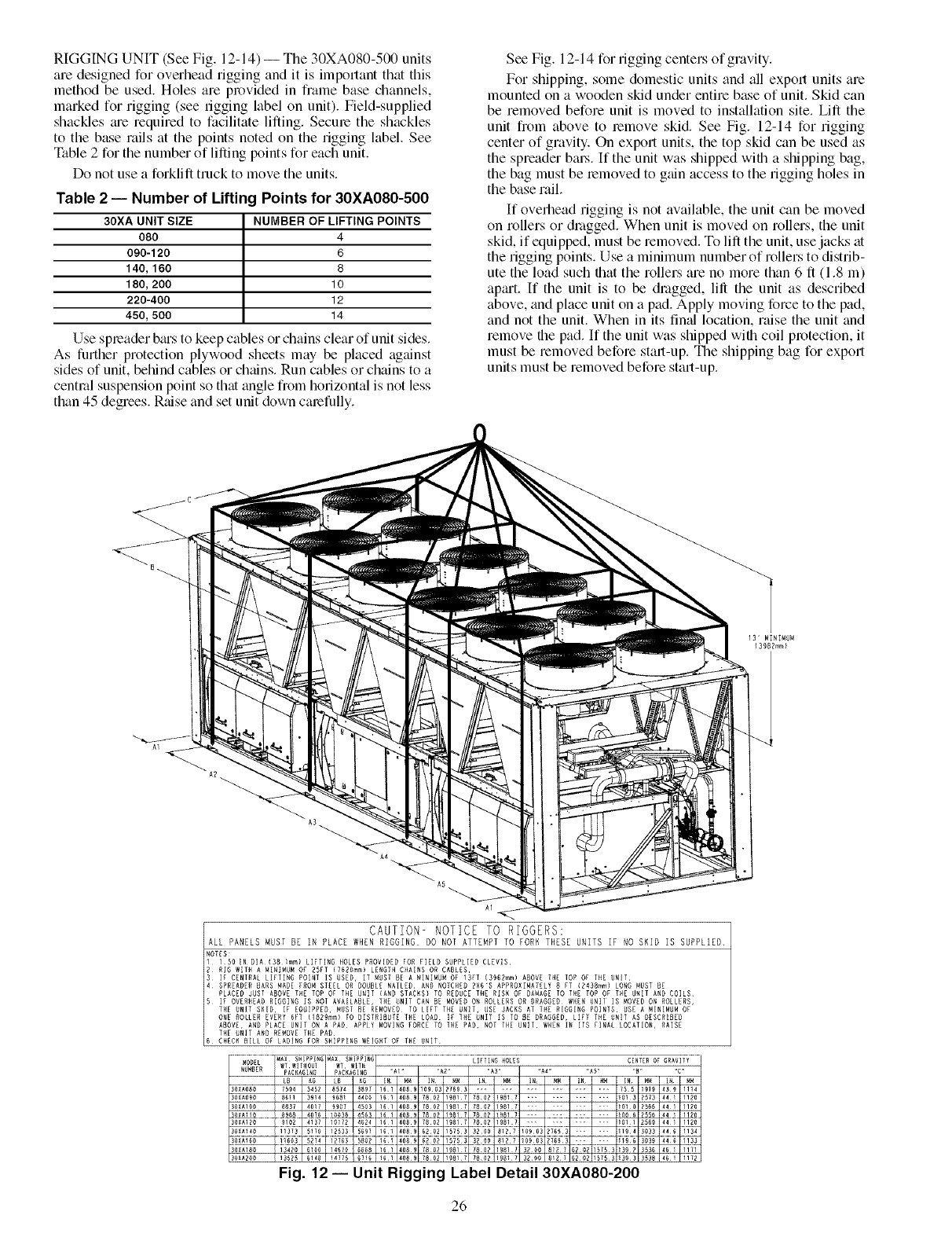
RIGGING UNIT (See Fig. 12-14) --The 30XA080-500 units
are designed for overhead rigging and it is impollant that this
method be used. Holes are provided in frame base channels,
marked for rigging (see rigging label on unit). Field-supplied
shackles tue required to facilitate lifting. Secure the shackles
to the base rails at the points noted on the rigging label. See
Table 2 for the number of lifting points for each unit.
Do not use a forklift truck to move the units.
Table 2 -- Number of Lifting Points for 30XA080-500
30XA UNIT SIZE NUMBER OF LIFTING POINTS
080 4
090-120 6
140, 160 8
180, 200 10
220-400 12
450, 500 14
Use spreader b_us to keep cables or chains clear of unit sides.
As further protection plywood sheets may be placed against
sides of unit, behind cables or ch_dns. Run cables or chains to a
central suspension point so that angle from horizontal is not less
than 45 degrees. Rtdse and set unit down cmefully.
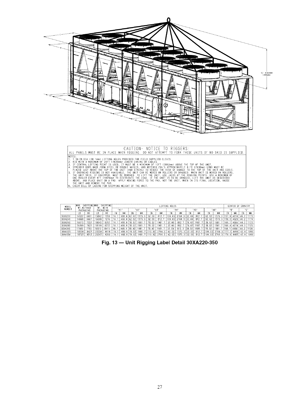
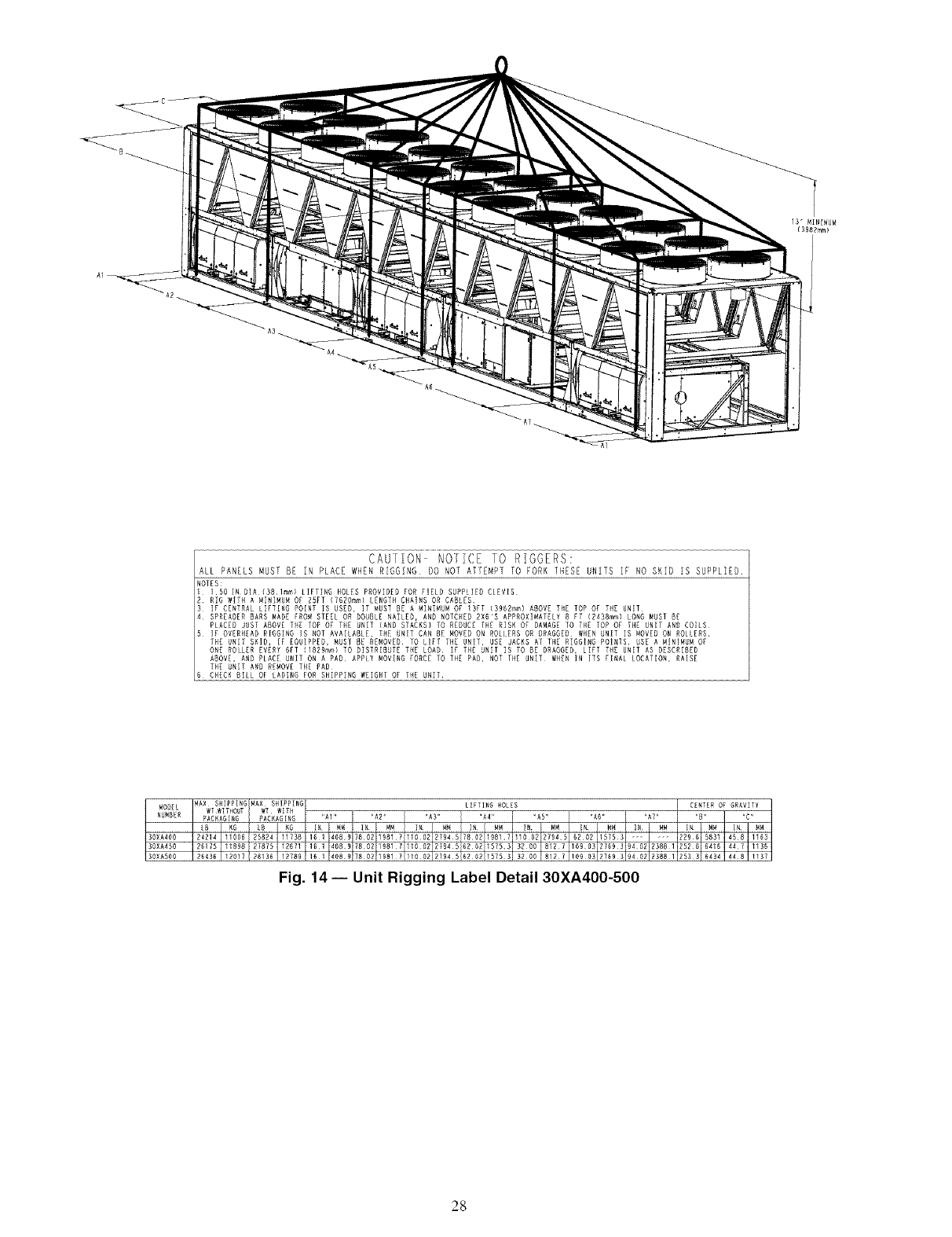
See Fig. 12-14 for rigging centers of gravity.
For shipping, some domestic units and all export units are
mounted on a wooden skid under entire base of unit. Skid can
be removed before unit is moved to installation site. Lift the
unit from above to lemove skid. See Fig. 12-14 for rigging
center of gravity. On export units, the top skid can be used as
the spreader baLs. If the unit was shipped with a shipping bag,
the bag must be removed to gain access to the rigging holes in
the base mil.
If overhead rigging is not available, the unit can be moved
on rollers or dragged. When unit is moved on rollers, the unit
skid, if equipped, must be removed. To lift the unit, use jacks at
the rigging points. Use a minimum number of rollers to distrib-
ute the load such that the rollers are no more than 6 ll (1.8 m)
apart. If the unit is to be dragged, H1l the unit as described
above, and place unit on a pad. Apply moving force to the pad,
and not the unit. When in its I]mfl location, raise the unit and
remove the pad. If the unit was shipped with coil protection, it
must be removed before start-up. The shipping bag for export
units must be removed before start-up.
13' MIRINUM
(398Rmm}
AR
A1
CAUTION- NOTICE TO RIGGERS:
ALL PANELS MUST BE IN PLACE WHEN RIGGING DO NOT ATTEMPT TO FORK THESE UMTS IF NO SKID IS SUPPLIED,
NOTES
I 5D IN DIA IBB Fm_) LIFTING HOLES PROVIDED FOR FIELD SUPPLIED CLEVIS
RIG WITH A _INIIIBM OR BSFT (TBZOmm) LENGTH CIAINS OR CABLES
IF CENTRAL LIFTING POINT IS USED, IT RUST BE A NINIMUN OF 13FT (39RBmm) ABOVE THE TOP OF THE UNIT
SPREAD R BARS BADE IROM SIEEL OR DOBBL NAILER, AND NOICHED R×6'S ARPROXIMAIELY B FT (B43Bmm) LONG MUST BE
PLACED JUST ABOVE THE TOP OF THE UNIT (AND STACKS1 TO REDUCE THE RISK OF DAMAGE TO TI_E TOP OF THE UNIT AND COILS
IF OVERHEAR RIGGING IS NO1 AVAILABLE, THE UNIT BAN BE MOVER ON ROLLERS OR BRAGGED WHEN UNII IS MOVED ON ROE ERS,
THE UNIT S_ID, [g EQDIPI_ED, MDST BE REMOV D TO lIFT THE _RIT, USE JACKS AT THE RIGGING POINTS _SE A MINIMUM OF
ONE ROLLER EVERY 6FT (IBZRmm) IO DISIRIBUIE IHE LOAD l_ THE UNIT IS lO BE DRAGGER, LIFE THE UNIT AS DESCRIBED
ABOVE, AND PLACE UNIT ON A PAD APP T MOVING FORCE TO THE PAD, NOT THE UNIT WHEN IN (Tg FINAl LOCATION, RAISE
T_E UNIT AND BEHOVE THE PAD
BHECI< BILL OF LADING FOR SH PPING WEIGHT DE THE UNIT
LI %1_G OLES CENTER OF GRAVITY
.U.BER%c"_'/g{¢d_"A'CKA"d_'_2"_" ._2.
t2o ;',_ 2, 2L I.... ,....
30XA08O 4 Z 4 _ _61 _OB9 10903 27693
3OXAO9O 8611 391_ 9_0_ 4400 161 _0B9 7802 19817 T802 1981 7 ............... _01 3 2573 44) 1120
)OXAIO0 8837 4017 9907 4503 16l 4089
E_E_!!D......................... 45r_ o!Lt_D_ 9
)OXA120 9102 4137 O72 4524 16 !it 408 9........................ i]iii_ii
ibx;_d;_........................iJbd-do?
30_A200 13525 6118 4775187 _ 16 I 1089 78 O_ 19817 7802 19817 3_ O0 81Z 7_2 02 15753 [39 _ 3538 16 1172
Fig. 12 -- Unit Rigging Label Detail 30XA080-200
26
CAUTION- NOTICE TO RIGGERS:
ALL PANELS MUST BE IN PLACE WHEN RIGGING DO NOT ATTEMPT TO FORK THESE UNITS IF NO SKID _S SUPPLIED
NOTES:
1 150 IN DIAIBB1n_I LIFTINB HOLES PROVIDED FOR FIELD SUPPLIED CLEVIS
R RIG WITH A MINIMUM OF 25FT (7SROmm) LENGTH CHAINS OR CABLES
3 IF BEN[RAL LIFIING POINT IS USED, II MUSI BE A MINIMUM Ol 13Fl (SRSRmm) ABOVE F_E lOP OF DIE UNII
4 SPREADER BARS MADE PROM STEEL OR DOUBLE NAILED, AND NOTCNRN 2X6'S APPROXIMATELY 8 IT 12438mm) LONG MUST BE
PLACED JUST ABOVE THE TOP OF THE UNIT (AND STACKS} TO REDUCE THE RISN OF DAMAGE TO TNE TOP OF TIE UNIT AND COILS
R IF OVERHEAD RIBGING IS NO[ AVAILABLE, [HE UNI[ CAN DE MOVED ON ROLLERS OR DRAGGED WHEN UNI[ IS MOVED ON ROLLERS,
THE UNIT SKIS, IF EQUIPPED, MUST DE REMOVED TO LIFT TNE UNIT, USE JACNS AT THE RIGGING POINTS USE A MINIMUM OF
ONE ROILER EVERY BFT (IRRRmml TO DISTRIBUTE THE LOAD IF THE UNIT IS TO BZ DRABBED, LIFT TNE UNIT AS DESCRIDEB
ABOVE, ANU PLACE UNIT ON A RAG APPLY MOVING FORCE TO THE PAR, NOT THE UNIT 8H[N !NIPS FINAL LOCATION, RAISE
THE UNIT AND REMOVE THE PAD
6. CHECK DILL O_ LADINB FOR SHIRRING WEIGNT OF THE UNII
MAX SHIPPING MAX SNIPPING LIFTING HOLES CENIER OF GRAVHY
N__OMDBE[_ tVI WITHOUT WI WITH
PACKAGING PAC{iAGING _AI ""AN .... A3" 'A4" 'AS" 'AS" 'D'r 'C'r
30XA220 5862 4 9 6NO_ 81 7 I09 03 0 81 7 N 46 2 1173
SOXA240 14668 6667 I600D 7276 161 4069 6ZS_ 15753 BNSS D127 10903 S?6UB _?00 D121 6SOZ 1SISB 1585 4025 462 1174
SOXA260 15515 7552 18045 8202 161 408 9 780_ 198I 7 7802 19817 3200 812 7 7802 19817 7802 19D1 7 1601 4066 44 2 1123
30XA280 16769 7622 1899 8272 6 408 9 780_ 9817 7802 987 3200 812 7 7802 987 7802 19817 604 4074 443 1125
30XA325 18539 8427 20059 918 1S 1 4089 780_ 19817 110 O_ 27945 62 02 15753 32 O0 8127 0903 2769 3 177 ] 4499 429 1090
Fig. 13 -- Unit Rigging Label Detail 30XA220-350
2?
13' MINIMUH
13982mm}
CAUFION NOFZ]E lO RIGGERS:
ALL PANELS MUST 8E IN PLACE WHEN RIGGING DO NOT AI]EMP] [0 FORK ]NESE UNI[S IF NO SHED IS SUPPLIED
NOTES:
150 !NBIA{B81mm) LIFTING HOLES PROVIDEB FOR FIELB SUPPLIED CIEVIS
il RIG WlIN A MINIMUM OF RSET (TBBOmml LENGTH CHAINS ON CABLES
IF CENTRAL LIFTING POINT IS USED, iT MUST BE A MINIMUM OF 13PP (3862_} ABOVE THE POP OF THE UNIT
N SPREADER BARS MAKE FROM STEEL OR BOM_LE NAILEB, ANB NOTCHED 2X6'S APPROXIMATELY 8 FT (2438mm) LONG MUST BE
PLACED JUST ABOVE THE TOP OF THE UNIT IAHD STACKS} TO REBUCE THE RISK OT DAMAGE TO THE TOP OF THE UNIT AND COILS
5 IF OVERNEAB RIGGING [S NOT AVAILABLE, THE UNIT CAN 8E MOVED ON ROLIERS OR DRAGGED WHEN UNIT IS MOVED ON ROllERS,
INE UNIt SN]B, iF EQN]PPEB, MUSE BE REMOVED TO LIEI !HE UNIT, USE JACHS Ar THE RIGGING POIH[S USE A MINIMUM O_
ONE ROLLER EVERY 6PT (1829_I TO DISPRIBUPE THE LOAN IP PHE UNIT IS TO _E DNAGGEB, LIPP THE UNIT AS DESCRIBED
ABOVE, ANB PLACE UNIT ON A PAD APHIY MOVING FORCE TO THE PAB, NOT THE NNIP WHEN IN ITS FINAL lOCATION, RAISE
TN_ UNIT AHD REMOVE THE RAD
MODEL _AX SHIRgING MAX SHIPPING
NUMBER WT WITHOUT W_ WIT_
PACNAGIMG PACNAG[NG _AI .... AR_¸
2LN3554 KS LB NG [N MM [N MM
30XA40O 11005 25824 11738 151 408_ 7802 19817
24214 28136 12789 151 4089 7802 19817
25175 27875 12671 151 4089 7802 1981730XA450 11898
30XA508 120_7
LIFTING NOLSS CEMTSR OF GRAVITY
"AS" "A4 .... AS" "AT" "AT.... B" "C'_
IN MM IN MM [N MM i IN _M i IN _M
flOOR 2794¸5 52¸02 IS753 ...... i!R95 5831i4S8 11531
32 O0 81R7 lO_OS 2759¸3 94¸02 RSBB Ii SR 5 5416i447 1136i
B280 812¸7 I090K 2759¸3 9402 RB8811!533 54B4 448 IIBTI
Fig. 14- Unit Rigging Label Detail 30XA400-500
2g
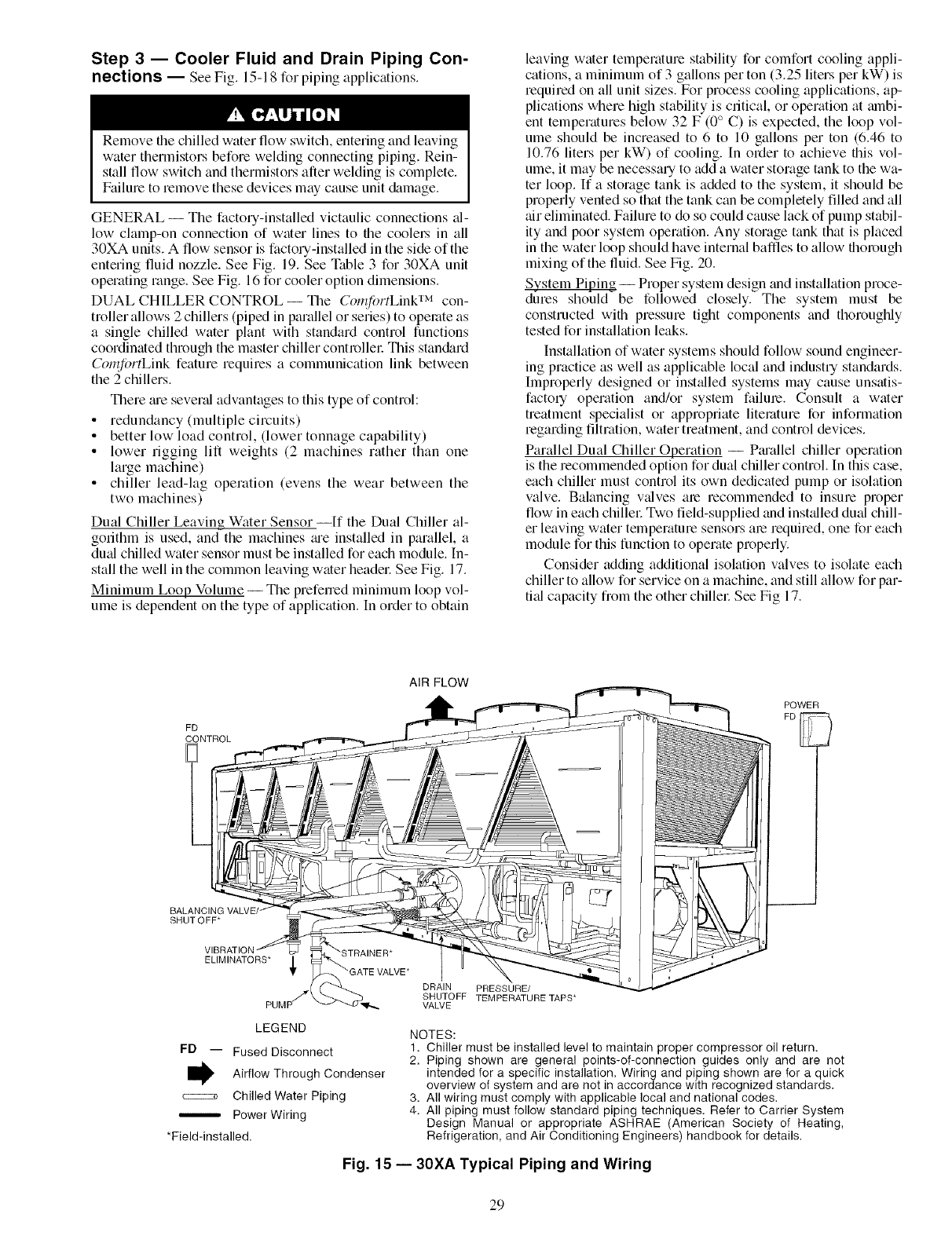
Step 3 -- Cooler Fluid and Drain Piping Con-
nections -- See Fig. 15-18 for piping applications.
Remove file chilled water flow switch, entering and leaving
water thermistors before welding connecting piping. Rein-
stall flow switch and thermistors after welding is complete.
Failure to remove these devices may cause unit &image.
GENERAL -- The factory-installed victaulic connections _d-
low clamp-on connection of water lines to file coolel_ in all
30XA units. A flow sensor is factory-installed in the side of the
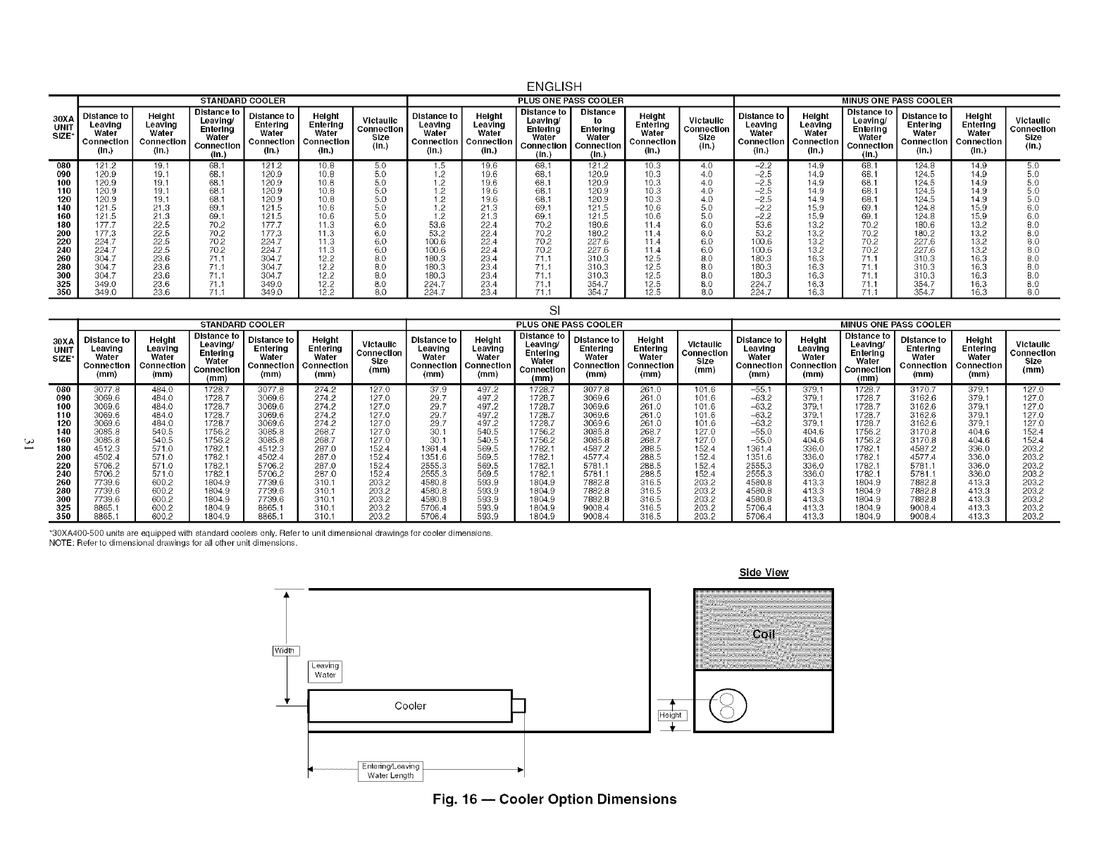
entering fluid nozzle. See Fig. 19. See Table 3 for 30XA unit
operating range. See Fig. 16 for cooler option dimensions.
DUAL CHILLER CONTROL -- The Co171/i_tTLinkTM con-
troller allows 2 chillers (piped in parallel or series) to operate as
a single chilled water plant with standard control functions
coordinated through the master chiller controllec This stan&trd
Co_71ibrtLink feature requires a communication link between
the 2 chillers.
There me severtd advantages to this type of control:
• redundancy (multiple circuits)
• better low load control, (lower tonnage capability)
• lower rigging lift weights (2 machines rather than one
large machine)
• chiller lead-lag operation (evens the wear between the
two machines)
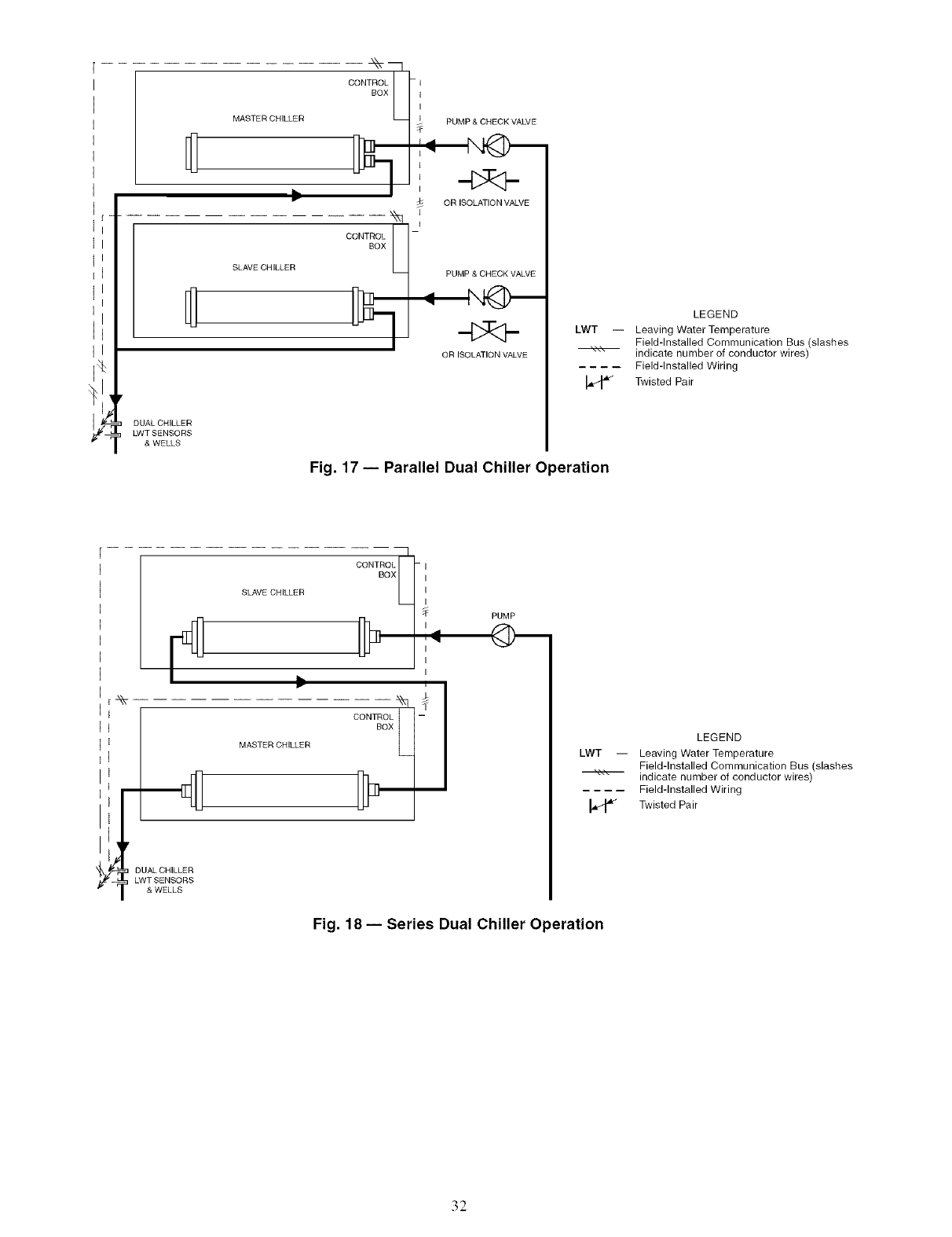
Dual Chiller Leaving Water Sensor --If the Dual Chiller al-
gorithm is used, and the machines me installed in parallel, a
dual chilled water sensor must be installed for each module. In-
stall the well in the common leaving water headec See Fig. 17.
Minimum Loop Volume -- The preferred minimum loop vol-
ume is dependent on the type of application. In order to obtain
leaving water temperature stability for comfort cooling appli-
cations, a minimum of 3 gallons per ton (3.25 liters per kW) is
required on all unit sizes. For process cooling applications, ap-
plications where high stability is critical, or operation at mnbi-
ent temperatures below 32 F (0 ° C) is expected, the loop vol-
ume should be increased to 6 to 10 gallons per ton (6.46 to
10.76 liters per kW) of cooling. In order to achieve tiffs vol-
ume, it may be necessary to add a water storage tank to the wa-
ter loop. If a storage tank is added to the system, it should be
properly vented so that the tank can be completely filled and all
air eliminated. Failure to do so could cause lack of pump stabil-
ity and poor system operation. Any storage tank that is placed
in the water loop should have internal baffles to allow fllorough
mixing of the fluid. See Fig. 20.
System Piping -- Proper system design and installation proce-
dures should be followed closely. The system must be
constructed with pressure tight components and thoroughly
tested for installation leaks.
Installation of water systems should follow sound engineer-
ing practice as well as applicable local and industry standards.
Improperly designed or inst_dled systems may cause unsatis-
factory operation and/or system failure. Consult a water
treatment specialist or appropriate literature for information
regarding filtration, water treatment, and control devices.
Parallel Dual Chiller Operation -- Pm'allel chiller operation
is the recommended option for dual chiller control. In this case,
each chiller must control its own dedicated pump or isolation
valve. Balancing v_dves are recommended to insure proper
flow in each chillec Two field-supplied and inst_dled dual chill-
er leaving water temperature sensors ale required, one for each
module for this function to operate properly.
Consider adding additional isolation valves to isolate each
chiller to allow for service on a machine, and still allow for par-
tied capacity from the other chillec See Fig 17.
FD
CONTROL
AIR FLOW
POWER
FD
BALANCIN(
SHUTOFF*
VIBRATI(
ELIMINATORS* _,
LEGEND
FD -- Fused Disconnect
Airflow Through Condenser
c====_ Chilled Water Piping
Power Wiring
*Field-installed.
DRAIN PRESSURE/
SHUTOFF TEMPERATURE TAPS*
VALVE
NOTES:
1. Chiller must be installed level to maintain proper compressor oil return.
2. Piping shown are general points-of-connection guides only and are not
intended for a specific installation. Wiring and piping shown are for a quick
overview of system and are not in accordance with recognized standards.
3. All wiring must comply with applicable local and national codes.
4. All piping must follow standard piping techniques. Refer to Carrier System
Design Manual or appropriate ASHRAE (American Society of Heating,
Refrigeration, and Air Conditioning Engineers) handbook for details.
Fig. 15 -- 30XA Typical Piping and Wiring
29
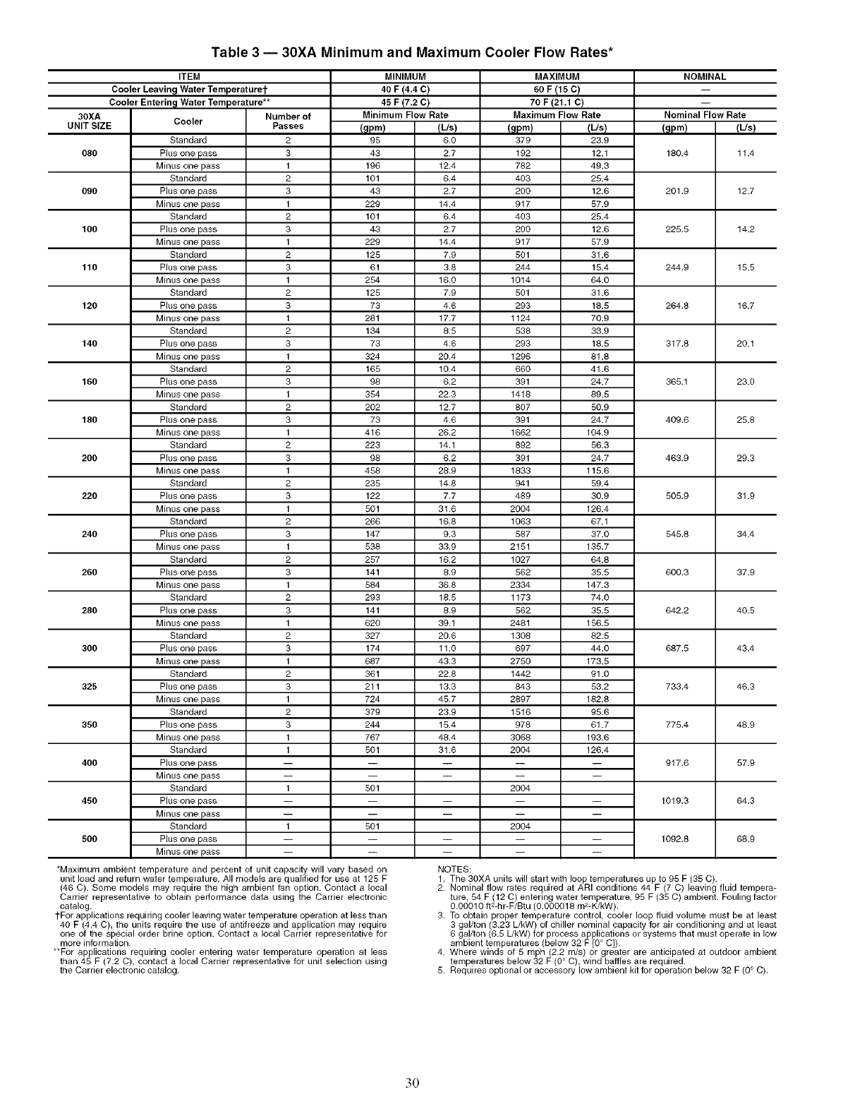
Table 3 -- 30XA Minimum and Maximum Cooler Flow Rates*
30XA
UNIT SIZE
080
090
100
110
120
140
160
180
200
220
24O
260
28O
3OO
325
35O
4OO
45O
5OO
ITEM
Cooler Leaving Water Temperaturet
Cooler Enterin_l Water Temperature**
Number of
Passes
2
3
1
2
3
1
2
3
1
2
3
1
2
3
1
2
3
1
2
3
1
2
3
1
2
3
1
2
3
1
2
3
1
2
3
1
2
3
1
2
3
1
2
3
1
2
3
1
1
1
1
MINIMUM
40 F (4.4 C)
45F17.2c!
Minimum Flow Rate
Cooler
Standard
Plus one pass
Minus one pass
Standard
Plus one pass
Minus one pass
Standard
Plus one pass
Minus one pass
Standard
Plus one pass
Minus one pass
Standard
Plus one pass
Minus one pass
Standard
Plus one pass
Minus one pass
Standard
Plus one pass
Minus one pass
Standard
Plus one pass
Minus one pass
Standard
Plus one pass
Minus one pass
Standard
Plus one pass
Minus one pass
Standard
Plus one pass
Minus one pass
Standard
Plus one pass
Minus one pass
Standard
Plus one pass
Minus one pass
Standard
Plus one pass
Minus one pass
Standard
Plus one pass
Minus one pass
Standard
Plus one pass
Minus one pass
Standard
Plus one pass
Minus one pass
Standard
Plus one pass
Minus one pass
Standard
Plus one pass
Minus one pass
IUs)
6.0
2.7
12.4
8.4
2.7
14.4
8.4
2.7
14.4
7.9
3.8
18.0
7.9
4.8
17.7
8.5
4.8
20.4
10.4
8.2
22.3
12.7
4.8
28.2
14.1
8.2
28.9
14.8
7.7
31.8
18.8
9.3
33.9
18.2
8.9
38.8
18.5
8.9
39.1
20.8
11.0
43.3
22.8
13.3
45.7
23.9
15.4
48.4
31.8
m
m
NOTES:
MAXIMUM
60 F (15 C)
70F(21.1C)
Maximum Flow Rate
(Us) (?pm)
23.9
12.1 180.4
49.3
25.4
12.6 201.9
57.9
25.4
12.6 225.5
57.9
31.6
15.4 244.9
84.0
31.6
18.5 264.8
70.9
33.9
18.5 317.8
81.8
41.6
24.7 365.1
89.5
50.9
24.7 409.8
104.9
56.3
24.7 463.9
115.6
59.4
30.9 505.9
126.4
87.1
37.0 545.8
135.7
84.8
35.5 800.3
147.3
74.0
35.5 842.2
156.5
82.5
44.0 887.5
173.5
91.0
53.2 733.4
182.8
95.6
81.7 775.4
193.6
126.4
-- 917.8
-- 1019.3
-- 1092.8
(_lpm)
379
192
782
403
200
917
403
200
917
5Ol
244
1014
501
293
1124
538
293
1298
860
391
1418
807
391
1862
892
391
1833
941
489
2004
1063
587
2151
1027
562
2334
1173
562
2481
1308
897
2750
1442
843
2897
1518
978
3068
2004
2004
2004
(_Ipm)
95
43
198
101
43
229
101
43
229
125
61
254
125
73
281
134
73
324
165
98
354
202
73
418
223
98
458
235
122
501
268
147
538
257
141
584
293
141
820
327
174
887
361
211
724
379
244
767
501
501
501
*Maximum ambient temperature and percent of unit capacity will vary based on
unit load and return water temperature. All models are qualified for use at 125 F
(48 C). Some models may require the high ambient fan option. Contact a local
Carrier representative to obtain performance data using the Carrier electronic
catalog.
1-For applications requiring cooler leaving water temperature operation at less than
40 F (4.4 C, the units require the use of antifreeze and application may require
one of the spec a order br ne opt on. Contact a oca Carrier representat ve for
more information.
**For applications requiring cooler entering water temperature operation at less
than 45 F (7.2 C, contact a local Carrier representative for unit selection using
the Cart ere ectron c cata og.
NOMINAL
Nominal Flow Rate
(us)
11.4
12.7
14.2
15.5
16.7
20.1
23.0
25.8
29.3
31.9
34.4
37.9
40.5
43.4
46.3
48.9
57.9
84.3
88.9
1. The 30XA units will start with loop temperatures up to 95 F (35 C.
2. Nominal flow rates required at ARI conditions 44 F (7 C) leaving fluid tempera-
ture, 54 F (12 C) entering water temperature, 95 F (35 C) ambient. Fouling factor
0.00010 ft2-h r-F/Btu (0.000018 m2-K/kW).
3. To obtain proper temperature control, cooler loop fluid volume must be at least
3 gal/ton 3.23 L/kW of chiller nominal capacity for air conditioning and at least
6 gal/ton (6.5 L/kW) for process applications or systems that must operate in low
ambient temperatures (below 32 F 0 ° C .
4. Where winds of 5 mph (2.2 m/s) or greater are anticipated at outdoor ambient
temperatures below 32 F (O° C), wind baffles are required.
5. Requires optional or accessory low ambient kit for operation below 32 F (0° C).
30
STANDARD COOLER
Distance to
30XA Distance to Height Leaving/ Distanceto Height Distance to Height
UNIT Leaving Leaving Entering Entering Entering Vlctaullc Leaving Leaving
SIZE* Water Water Water Water Water ConnectionSize Water Water
Connection Connection Connection Connection Connection Connection
Connection (in.)
(in.) (in.) (in.) (in.) (in.) (in.) (in.)
080 121.2 19.1 68.1 121.2 10.8 5.0 1.5 19.6
090 120.9 19.1 68.1 120.9 10.8 5.0 1.2 19.6
100 120.9 19.1 68.1 120.9 10.8 5.0 1.2 19.6
110 120.9 19.1 66.1 120.9 10.6 5.0 1.2 19.6
120 120.9 19.1 68.1 120.9 10.6 5.0 1.2 19.6
140 121.5 21.3 69.1 121.5 10.6 5.0 1.2 21.3
160 121.5 21.3 69.1 121.5 10.6 5.0 1.2 21.3
180 177.7 22.5 70.2 177.7 11.3 6.0 53.6 22.4
200 177.3 22.5 70.2 177.3 11.3 6.0 53.2 22.4
220 224.7 22.5 70.2 224.7 11.3 6.0 100.6 22.4
240 224.7 22.5 70.2 224.7 11.3 6.0 100.6 22.4
260 304.7 23.6 71.1 304.7 12.2 8.0 180.3 23.4
280 304.7 28.6 71.1 304.7 12.2 8.0 160.3 23.4
300 304.7 28.6 71.1 304.7 12.2 8.0 160.3 23.4
328 349.0 23.6 71.1 349.0 12.2 8.0 224.7 23.4
380 349.0 23.6 71.1 349.0 12.2 8.0 224.7 23.4
ENGLISH
PLUS ONE PASS COOLER
Distance to Distance
Leaving/ to
Entering Entering
Water Water
ConnecUon Connection Connecttan
(in.) (in.) (in.)
68.1 121.2 10.8
68.1 120.9 10.3
68.1 120.9 10.3
66.1 120.9 10.3
68.1 120.9 10.3
69.1 121.5 10.6
69.1 121.5 10.6
70.2 180.6 11.4
70.2 180.2 11.4
70.2 227.6 11.4
70.2 227.6 11.4
71.1 310.3 12.5
71.1 310.3 12.5
71.1 310.3 12.5
71.1 354.7 12.5
71.1 354.7 12.5
MINUS ONE PASS COOLER
Distance to
Height Distance to Height Leaving/ Distance to Height
Entering Vlctaullc Leaving Leaving Entering Entering Entering Vlctaullc
Water Connection Water Water Water Water Connection
Size Water Size
(in.) Connection Connection Connection Connection
Connection (in.)
(in.) (in.) (in.) (in.) (in.)
4.0 -2.2 14.9 68.1 124.8 14.9 5.0
4.0 -2.5 14.9 66.1 124.5 14.9 5.0
4.0 -2.5 14.9 68.1 124.5 14.9 5.0
4.0 -2.5 14.9 66.1 124.5 14.9 5.0
4.0 -2.5 14.9 66.1 124.5 14.9 5.0
5.0 -2.2 15.9 69.1 124.8 15.9 6.0
5.0 -2.2 15.9 69.1 124.6 15.9 6.0
6.0 53.6 13.2 70.2 160.6 13.2 8.0
6.0 53.2 13.2 70.2 180.2 13.2 8.0
6.0 100.6 13.2 70.2 227.6 13.2 6.0
6.0 100.6 13.2 70.2 227.6 13.2 8.0
8.0 180.3 16.3 71.1 310.3 16.3 8.0
8.0 180.3 16.3 71.1 310.3 16.3 8.0
8.0 180.3 16.3 71.1 310.3 16.3 8.0
8.0 224.7 16.3 71.1 354.7 16.3 8.0
8.0 224.7 16.3 71.1 354.7 16.3 8.0
STANDARD COOLER
Distance to
30XA Distanceto Height Distance to Distance to Height Distanceto Height Leaving/
UNIT Leaving Leaving Leaving/ Entering Entering Vlctaullc Leaving Leaving Entering
Entering Water Water Connection Water Water
SIZE* Water Water Water Size Water
Connection Connection Connection Connection Connection Connection
Connection (ram) Connection
(ram) (ram) (ram) (ram) (ram) (ram) (ram) (mm)
080 3077.8 484.0 1728.7 3077.8 274.2 127.0 37.9 497.2 1728.7
090 3069.6 484.0 1726.7 3069.6 274.2 127.0 29.7 497.2 1728.7
100 3069.6 484.0 1728.7 3069.6 274.2 127.0 29.7 497.2 1728.7
110 3069.6 484.0 1728.7 3069.6 274.2 127.0 29.7 497.2 1728.7
120 3069.6 484.0 1726.7 3069.6 274.2 127.0 29.7 497.2 1726.7
140 3085.8 540.6 1756.2 3086.8 268.7 127.0 30.1 540.6 1756.2
'._ 160 3085.8 540.6 1756.2 3085.8 268.7 127.0 30.1 540.5 1756.2
180 4512.3 571.0 1782.1 4512.3 287.0 152.4 1361.4 569.5 1782.1
200 4502.4 571.0 1782.1 4502.4 287.0 152.4 1351.6 569.5 1782.1
220 5706.2 571.0 1782.1 5706.2 287.0 152.4 2555.3 569.5 1782.1
240 5706.2 571.0 1762.1 5706.2 287.0 152.4 2555.3 569.6 1762.1
260 7739.6 600.2 1804.9 7739.6 310.1 203.2 4580.8 593.9 1804.9
280 7739.6 600.2 1804.9 7739.6 310.1 203.2 4580.8 593.9 1804.9
300 7739.6 600.2 1604.9 7739.6 310.1 203.2 4580.8 593.9 1804.9
325 8865.1 600.2 1804.9 8865.1 310.1 203.2 5706.4 593.9 1804.9
350 8865.1 600.2 1804.9 8865.1 310.1 203.2 5706.4 593.9 1804.9
SI
PLUS ONE PASS COOLER
Connection Connection
(ram) (ram)
3077.8 261.0
3069.6 261.0
3069.6 261.0
3069.6 261.0
3069.6 261.0
3086.8 268.7
3085.8 268.7
4587.2 288.5
4577.4 288.5
5781.1 288.5
5781.1 286.5
7882.8 316.5
7882.8 316.5
7682.8 316.5
9008.4 316.5
9008.4 316.5
MINUS ONE PASS COOLER
DIstanceto Height Distance to Height Distance to Dlstanceto Height
Entering Entering Vlctaullc Leaving Leaving Leaving/ Entering Entering Vlctaullc
Water Water Connection Water Water Entering Water Water Connection
Size Water Size
(ram) Connection Connection Connection Connection
Connection (ram)
(ram) (ram) (ram) (ram) (ram)
101.6 =55.1 379.1 1728.7 3170.7 379.1 127.0
101.6 43.2 379.1 1728.7 3162.6 379.1 127.0
101.6 43.2 379.1 1728.7 3162.6 379.1 127.0
101.6 43.2 379.1 1728.7 3162.6 379.1 127.0
101.6 43.2 379.1 1726.7 3162.6 379.1 127.0
127.0 -55.0 404.6 1756.2 3170.8 404.6 152.4
127.0 -55.0 404.6 1766.2 3170.8 404.6 152.4
152.4 1361.4 336.0 1782.1 4587.2 336.0 208.2
152.4 1351.6 336.0 1782.1 4577.4 336.0 203.2
152.4 2555.3 336.0 1782.1 5781.1 336.0 203.2
152.4 2555.3 336.0 1762.1 5781.1 336.0 203.2
293.2 4580.8 413.3 1804.9 7862.8 413.3 203.2
203.2 4580.8 413.3 1804.9 7862.8 413.3 203.2
208.2 4580.8 418.3 1804.9 7682.8 418.3 208.2
203.2 5706.4 413.3 1804.9 9008.4 413.3 203.2
203.2 5706.4 413.3 1804.9 9008.4 413.3 203.2
"30XA400-500 units are eq uipped wi_ standard coolers one!, Refer to unit dimensional drawings for cooler dimensions.
NOTE: Refer to dimensional drawings for all oth er unit dimensions.
Side View
Cooler I
ql [ Entering/Leaving ]
LWater Length J
Fig. 16 -- Cooler Option Dimensions
I
DUAL CHILLER
LWT SENSORS
& WELLS
CO.T_L
MASTER CHILLER
SLAVE CHILLER
-I
I
I
#
I
I
I
I
_l
PUMP & CHECK VALVE
-4>r
OR ISOLATION VALVE
PUMP & CHECK VALVE
-bTq-
OR ISOLATION VALVE
LEGEND
LWT -- Leaving Water Temperature
Field-Installed Communication Bus (slashes
indicate number of conductor wires)
Field-Installed Wiring
Twisted Pair
Fig. 17 -- Parallel Dual Chiller Operation
SLAVECH,LLER OONT#oO_l
I
I
I=
MASTER CHILLER CONTROL _.BOX
I
I
I
I
I
,q
I
I
I
PUMP
Fig. 18- Series Dual Chiller Operation
LWT
LEGEND
-- Leaving Water Temperature
Field-Installed Communication Bus (slashes
indicate number of conductor wires)
Field-Installed Wiring
Twisted Pair
32
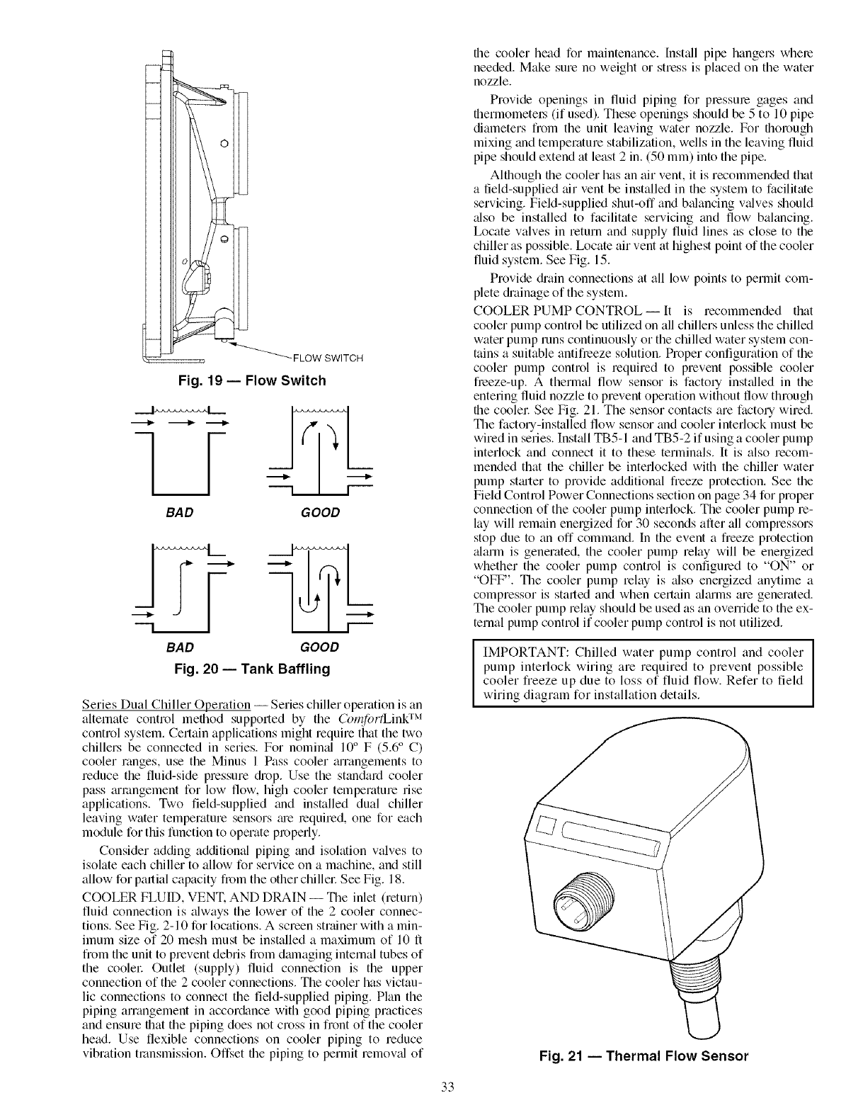
_ FLOW SWITCH
Fig. 19 -- Flow Switch
-[_F
BAD GOOD
BAD GOOD
Fig. 20 -- Tank Baffling
Series Dual Chiller Operation -- Series chiller operation is an
alternate control method supported by the Con_/ortLink TM
control system. Certain applications might require that the two
chillers be connected in series. For nomimfl 10 ° F (5.6 ° C)
cooler ranges, use the Minus 1 Pass cooler mTangements to
reduce the fluid-side pressure diop. Use the standard cooler
pass mmngement for low flow, high cooler temperature rise
applications. Two field-supplied and installed dual chiller
leaving water temperature sensors me required, one for each
module for this function to operate properly.
Consider adding additional piping and isolation valves to
isolate each chiller to allow for service on a machine, and still
allow for partial capacity fiom the other chillel: See Fig. 18.
COOLER FLUID, VENT. AND DRAIN -- The inlet (return)
fluid connection is always the lower of the 2 cooler connec-
tions. See Fig. 2-10 for locations. A screen strainer with a min-
imum size of 20 mesh must be installed a maximum of 10 ft
fi'om the unit to prevent debris from dmnaging internal tubes of
the coolel: Outlet (supply) fluid connection is the upper
connection of the 2 cooler connections. The cooler has victau-
lic connections to connect the field-supplied piping. Plan the
piping arrangement in accor&mce with good piping practices
and ensure that the piping does not cross in front of the cooler
head. Use flexible connections on cooler piping to reduce
vibration transmission. Offset the piping to permit remover of
the cooler head for maintenance. [nst_dl pipe hangers where
needed. Make sum no weight or stress is placed on the water
nozzle.
Provide openings in fluid piping for pressure gages and
thermometel_ (if used). These openings should be 5 to 10 pipe
diameters from the unit leaving water nozzle. For thorough
mixing and temperature stabilization, wells in the leaving fluid
pipe should extend at least 2 in. (50 mm) into the pipe.
Although the cooler has an air vent, it is recommended that
a field-supplied air vent be installed in the system to facilitate
servicing. Field-supplied shut-off and balancing v_dves should
also be installed to facilitate servicing and flow balancing.
Ix_cate valves in return and supply fluid lines as close to the
chiller as possible. Ix)cate air vent at highest point of the cooler
fluid system. See Fig. 15.
Provide diain connections at all low points to permit com-
plete di'ainage of the system.
COOLER PUMP CONTROL--It is recommended that
cooler pump control be utilized on all chillers unless the chilled
water pump runs continuously or the chilled water system con-
tains a suitable antifieeze solution. Proper configuration of the
cooler pump control is required to prevent possible cooler
fieeze-up. A thermal flow sensor is facto qinst_dled in the
entering fluid nozzle to prevent operation without flow through
the coolec See Fig. 21. The sensor contacts am facto Uwired.
The factou-installed flow sensor and cooler interlock must be
wired in series. Install TBS-I and TBS-2 if using a cooler pump
interlock and connect it to these terminals. It is also recom-
mended that the chiller be interlocked with the chiller water
pump starter to provide additional freeze protection. See the
Field Control Power Connections section on page 34 for proper
connection of the cooler pump interlock. The cooler pump re-
lay will remain energized for 30 seconds after all compressors
stop due to an off command. In the event a freeze protection
_flarm is generated, the cooler pump relay will be energized
whether the cooler pump control is configured to "ON" or
"OFF". The cooler pump relay is also energized anytime a
compressor is started and when certain _dmms are generated.
The cooler pump relay should be used as an override to the ex-
ternal pump control if cooler pump control is not utilized.
I
IMPORTANT: Chilled water pump control and cooler [
pump interlock wiring are required to prevent possible I
cooler fieeze up due to loss of fluid flow. Refer to field
wiring diagram for installation details.
@
Fig. 21 -- Thermal Flow Sensor
33
BRINE UNITS- Special factory modifications to the units
are required to _dlow them to operate at fluid temperatures less
than 34 F (1.1 C). Be sure that the fluid has sufficient inllibited
glycol or other suitable corrosion-lesistant antitYeeze solution
to prevent cooler freeze-up.
WATER TREATMENT- Untleated or improperly tleated
water may result in corrosion, sc_ding, erosion, or algae. The
services of a qu_dified water tleatment specialist should be
obtained to develop and monitor a treatment program.
Water must be within design flow limits, clean, and treated
to ensure proper chiller performance and reduce the poten-
tial of tube damage due to corrosion, scaling, erosion, and
algae. Cmrier assumes no responsibility for chiller &_mage
resulting from untreated or improperly treated watel:
NOTE: Do not use automobile anti-freeze, or any other fluid
that is not approved for heat exchanger duty. Only use appro-
priately inhibited glycols, concentrated to provide adequate
protection for the temperature considered.
PREPARATION FOR YEAR-ROUND OPERATION -- In
areas where the piping or unit is exposed to 32 F (0 ° C) or
lower ambient temperatures, freeze-up protection is required
using inhibited glycol or other suitable corrosion-resistant anti-
fleeze solution and electric heater tapes. Heater tapes on piping
should have a rating for ;u'ea mnbient temperatures and be cov-
ered with a suitable thickness of closed-cell insulation. Route
power for the heater tapes from a sepm'ately fused disconnect.
Mount the disconnect within sight from the unit per local or
NEC (National Electric Code) codes. Identify disconnect at
heater tape power source with a warning that power must not
be turned off except when servicing unit.
IMPORTANT: Adding antifreeze solution is the only
certain means of protecting the unit flom freeze-up if
heater fails or electrical power is interrupted or lost
while temperatures are below 32 F (0 ° C).
IMPORTANT: Before starting the unit, be sure all of
the air has been purged from the system.
A di'ain connection is located at the bottom of the cooler
head. See Fig. 2-10 for connection location. Install shut-off
v_dves to the drain line before filling the system with fluid.
Low Ambient Temperature Head Pressure Control -- If the
unit is equipped with the low ambient temperature head pres-
sure control option, field-fabricated and field-installed wind
baffles are required if the wind velocity is anticipated to be
gleater than 5 mph (8 km/h). Two different baffles may be re-
quired, facing the control box. Wind baffles should be con-
stmcted with minimum 18-gage g_dvanized sheet metal or oth-
er suitable corrosion-resistance material with cross breaks for
strength. See Fig. 22. Use field-supplied screws to attach baf-
fles to the corner posts of the machine. Be sure to hem or turn a
flange on _dl edges to eliminate sharp edges on the baffles.
To avoid possibility of electric_d shock, open all discon-
nects before installing or servicing this accessory.
To avoid dmnage to the refl'igerant coils and electrical com-
ponents, use extreme ctue when drilling screw holes and
screwing in fasteners.
Mount the smaller height baffle on units with a control box
located on the end of the unit. It is recommended that the upper
notches be used for mounting the baffles. This reduces the risk
of dmnaging the coil while drilling a mounting hole. Ix_osen
the upper comer post bolts and slide the baffle under the bolt
and washel: Tighten the bolt. Drill holes in the bottom of the
flange of the baffle and mount with two sclews to secure the
bottom of the baffle to the comer post. Repeat the process for
the opposite end. See Fig. 22.
PREPARATION FOR WINTER SHUTDOWN -- If the unit
is not operatiomfl during the winter months, at the end of cool-
ing season complete the following steps.
Failure to remove power before draining heater equipped
coolers can result in heater tape and insulation damage.
1. [f the cooler will not be dndned do not shut off power
disconnect during off-season shutdown. If the cooler is
drained, open the circuit breaker for the heater. CB-HT
(circuit breaker heater) or shut off power during off-
season shutdown.
2. Draining the fluid from the system is highly recommended.
3. Isolate the cooler from the rest of the system with water
shutoff v_dves.
4. Completely fill the cooler with a mixture of half water
and half inhibited glycol solution (or other suitable cono-
sion-inhibitive antifreeze) for 15° F (8.3 ° C) below the
expected low ambient temperature conditions.
5. Leave the cooler filled with the antifreeze solution for the
wintel: or drain if desired. Be sure to deenergize heaters
(if installed) as explained in Step 1 to plevent damage.
Use an approved method of disposal when lemoving anti-
freeze solution.
6. At the beginning of the next cooling season, be sure that
there is refrigerant pressure on each circuit before
refilling coolel: add recommended inhibitol: trod reset the
CB-HT (circuit breaker heater) (if opened) or restore
powel:
Step 4 -- Make Electrical Connections
Electrical shock can cause personal injury and death. Shut
off _fll power to this equipment during inst_fllation. There
may be more than one disconnect switch. Tag all discon-
nect locations to alert othel_ not to restore power until work
is completed.
POWER SUPPLY --The electrical ch_u'acteristics of the
available power supply must agree with the unit nameplate
rating. Supply voltage must be within the limits shown. See
Tables 4-6 for electric_d and configuration &tta.
FIELD POWER CONNECTIONS (See Fig. 23) -- All pow-
er wiring must comply with applicable local and national
codes. Install field-supplied, branch circuit lhsed disconnect(s)
of a type that can be locked off or open. Disconnect(s) must be
located within sight and readily accessible from the unit in
compliance with NEC Article 440-14 (U.S.A.). See Tables 4
and 5 for unit electrical &_ta. See Table 6 for compressor and
fan electrical &tta.
IMPORTANT: The 30XA units have a factory-inst_dled
option available for a non-fused disconnect for unit power
supply. If the unit is equipped with this option, all field
power wiring should be made to the non-fused disconnect
since no terminal blocks are supplied.
34
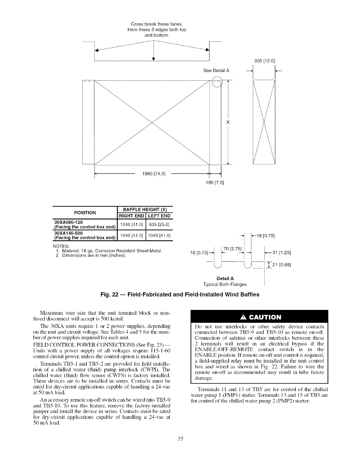
Cross break these faces.
Hem these 3 edges both top
and bottom.
\
1880 [74.0]
See Detail A
305 [12.0]
4
POSITION
30XA080-120
(Facing the control box end I
30XA140-500
(Facing the control box end)
BAFFLE HEIGHT (X)
RIGHT END LEFT END
1040 [41.0] 635 [25.0]
1040 [41.0] 1040 [41.0]
NOTES:
1. Material: 18 ga. Corrosion Resistant Sheet Metal.
2. Dimensions are in mm [inches],
Fig. 22 -- Field-Fabricated
t 1--18 [0.75]
18 [0.75] _'_ _Z0 [2"7 _*_31 [1.25]
..............L_SDetailAes_ _21 [0.88]
Typical Both Flang
and Field-Installed Wind Baffles
Maximum wile size that the unit terminal block or non-
fused disconnect will accept is 500 kcmil.
The 30XA units require 1 or 2 power supplies, depending
on the unit and circuit voltage. See Tables 4 and 5 for the num-
ber of power supplies required for each unit.
FIELD CONTROL POWER CONNECTIONS (See Fig. 23) --
Units with a power supply of all voltages require 115-1-60
control circuit power, unless the control option is installed.
Terminals TB5-1 and TB5-2 ale provided for field installa-
tion of a chilled water (fluid) pump interlock (CWPI). Tile
chilled water (fluid) flow sensor (CWFS) is factory installed.
These devices ale to be installed in series. Contacts must be
rated for dry-circuit applications capable of handling a 24-vac
at 50 mA load.
An accessory remote on-off switch c:m be wired into TB5-9
and TB5-10. To use this feature, remove the factory-installed
jumper and install the device in series. Contacts must be rated
for dry-circuit applications capable of handling a 24-vac at
50 mA load.
Do not use interlocks or other safety device contacts
connected between TB5-9 and TB5-10 as remote on-off.
Connection of safeties or other interlocks between these
2 terminals will result in an electrical bypass if the
ENABLE-OFF-REMOTE contact switch is in the
ENABLE position. If remote on-offunit control is required,
a field-supplied lelay must be installed in the unit control
box and wired as shown in Fig. 22. Failure to wire the
remote on-off as recommended may result in tube freeze
&tmage.
Terlninals 11 and 13 of TB5 me for control of the chilled
water pump 1 (PMPI) startel: Terminals 13 and 15 of TB5 me
for control of the chilled water pump 2 (PMP2) startel:
35
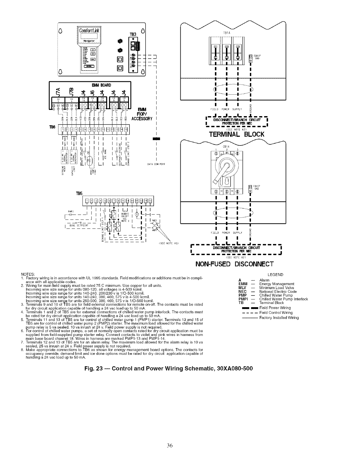
iO
iO
.:.=_
,_ _ _ _ _ _ _ _ _ ACCESSORY
i_l i_l _l I I I I_1 I:
i Iiili
LI LI_LI_
i
I
I
I
I
DA_A_OMFORT
T_A
I I I I
I I I I
I I I I
I I I I
I I I
FIELO POW[R SUPPLT
,- &Be
{SEE NOTE_2_
TERMINAL BLOCK
C81A
I I I I
I I I I
M-L
I I I i
_]_LOI _o_I suP,_I !
I I I I
f. .... !.. !.. L..a --
DISCONNECT/BRANCH CIRCUIT I
IPRO_C'nO_ _ BEG I J
(SEE NOTE _2_
NON-FUSED DISCONNECT
NOTES:
1. Factory wiring is in accordance with UL 1995 standard& Field modifications or additions must be in compli-
2. _iCegltohr a_ll_,P fPilie_bslepCp_d_-_ustbe rated 75 C ,'ninimurn. Use copper for allunits.
Incoming wire size range for units 080-120, all voltages is 4-500 kcmil.
Incoming wire size range for units 140-240, 200/230 v is 1/0-500 kcrnil.
Incoming wire size range for units 140-240, 380,460, 575 v is 4%00 kcmil.
3. [peCr°/_1iliads_ rell_i Zleora_l_-_ _° r UenitoSr2ieOd500_ 380,4o610 ,eSctTiSlvsi;lr/O-m500 koOnm(Hif,The contacts must be rated
4. _errdrl_nci_c_ita_jP_Co_tl_B_aPeabloer °fxthea_ldallll_gonal2e4ctVoa,_ 50alt_rApump interlock. The contacts must
be rated for dry circuit application capable of handling a 24 vac load up to 50 mA.
5. TB5 are for control of chilledTer_'ninals 11 and 13 of TB5 _et fOrpCOn_r_l ,_,_ _---_-_- _ _-_, ,_,_ofc_Hedtwa_rr J_umpl [,,P,M,,Pll)starr tller:,,Ter,'ni!la/s 13 andwater15Ofchilled
6. _UmcPo[_lra_ i_ c5_lesde_lletd,r 10Vapin, raUShe_to24oV_mFi_llydoPpeWecrSUtPaPcltYsiSal]eOc__eq_irrydcircui t application must be
supplied from field-supplied pump starter relay. Connect contacts to violet and pink wires in harness from
main base board channel l& Wires in harness are marked PMP1-13 and PMP1-14.
7. Terminals 12 and 13 of TB5 are for an alarm relay. The maximum load allowed for the alarm relay is 10 va
8, _/_ & ;"*11 _" " '34 "E_l__al_edapproprIiateScont,#ctions_o -_'"_*_''1" ;_ "_÷*_"";*_'4_Be_ss_oH_°foIrei_,_gy_anagernent board options. The contacts for
_CC_liagCaY_,_e_icd&ddeumpal_d/_imt,_l]d ice done options must be rated for dry circuit application capable of
LEGEND
A-- Alarm
EMM -- Energy Management
MLV I Minimum Load Valve
NEC -- National Electric Code
PMP -- Chilled Water Pump
PMPI I Chilled Water Pump Interlock
TB I Terminal Block
iiii iiii Field Power Wiring
.... Field Control Wiring
-- Factory Installed Wiring
Fig. 23 -- Control and Power Wiring Schematic, 30XA080-500
36
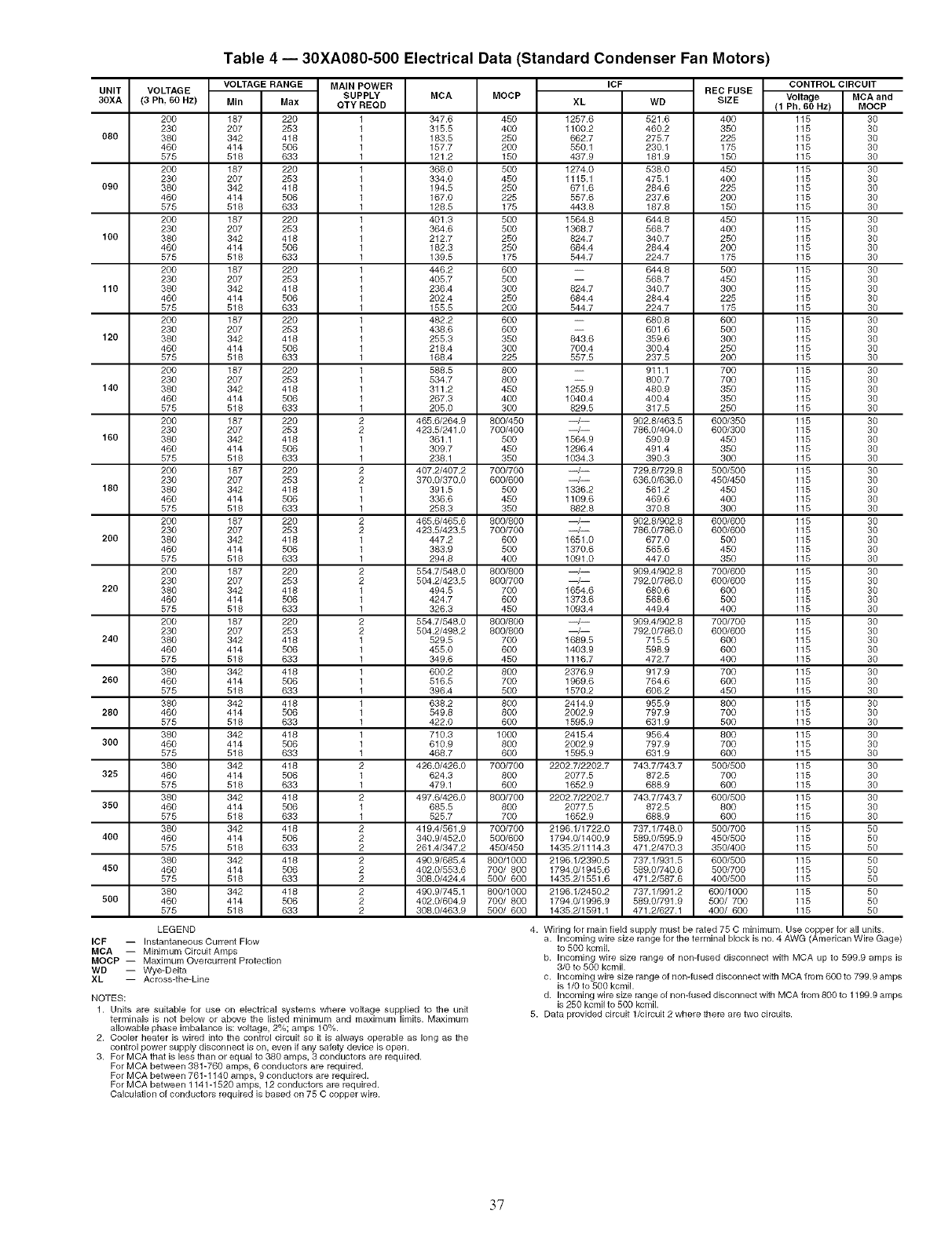
Table 4 -- 30XA080-500 Electrical Data (Standard Condenser Fan Motors)
UNIT
30XA
080
090
1O0
11o
120
140
160
180
200
220
240
260
280
300
325
350
400
450
500
VOLTAGE RANGE MAIN POWER
VOLTAGE SUPPLY
(3 Ph, 80 Hz) MIn Max OTY REOD
200 187 220 1
230 207 253 1
380 342 418 1
460 414 506 1
575 518 633 1
200 187 220 1
230 207 253 1
380 342 418 1
460 414 506 1
575 518 633 1
200 187 220 1
230 207 253 1
380 342 418 1
460 414 506 1
575 518 633 1
200 187 220 1
230 207 253 1
380 342 418 1
460 414 506 1
575 518 633 1
200 187 220 1
230 207 253 1
380 342 418 1
460 414 506 1
575 518 633 1
200 187 220 1
230 207 253 1
380 342 418 1
460 414 506 1
575 518 633 1
200 187 220 2
230 207 253 2
380 342 418 1
460 414 506 1
575 518 633 1
200 187 220 2
230 207 253 2
380 342 418 1
460 414 506 1
575 518 633 1
200 187 220 2
230 207 253 2
380 342 418 1
460 414 506 1
575 518 633 1
200 187 220 2
230 207 253 2
380 342 418 1
460 414 506 1
575 518 633 1
200 187 220 2
230 207 253 2
380 342 418 1
460 414 506 1
575 518 633 1
380 342 418 1
460 414 506 1
575 518 633 1
380 342 418 1
460 414 506 1
575 518 633 1
380 342 418 1
460 414 506 1
575 518 633 1
380 342 418 2
460 414 506 1
575 518 633 1
380 342 418 2
460 414 506 1
575 518 633 1
380 342 418 2
460 414 506 2
575 518 633 2
380 342 418 2
460 414 506 2
575 518 633 2
380 342 418 2
460 414 506 2
575 518 633 2
MCA MOCP XL
347.6 450 1257.6
315.5 400 1100.2
183.5 250 662.7
157.7 200 550.1
121.2 150 437.9
368.0 500 1274.0
334.0 450 1115.1
194.5 250 671.6
167.0 225 557.6
128.5 175 443.8
401.3 500 1564.8
364.6 500 1368.7
212.7 250 824.7
182.3 250 684.4
139.5 175 544.7
446.2 600 --
405.7 500 --
236.4 300 824.7
202.4 250 684.4
155.5 200 544.7
482.2 600 --
438.6 600 --
255.3 350 843.6
218.4 300 700.4
168.4 225 557.5
588.5 800 --
534.7 800
311.2 450 1255.9
267.3 400 1040.4
205.0 300 829.5
465.6/264.9 800/450 --/--
423.5/241.0 700/400 --/--
361.1 500 1564.9
309.7 450 1296.4
238.1 350 1034.3
407.2/407.2 700/700 --/--
370.0/370.0 600/600 --/--
391.5 500 1336.2
336.6 450 1109.6
258.3 350 882.8
465.6/465.6 800/800 --/--
423.5/423.5 700/700 --/--
447.2 600 1651.0
383.9 500 1370.6
294.8 400 1091.0
554.7/548.0 800/800 --/--
504.2/423.5 800/700 --/--
494.5 700 1654.6
424.7 600 1373.6
326.3 450 1093.4
554.7/548.0 800/800 --/--
504.2/498.2 800/800 --/--
529.5 700 1689.5
455.0 600 1403.9
349.6 450 1116.7
600.2 800 2376.9
516.5 700 1969.6
396.4 500 1570.2
638.2 800 2414.9
549.8 800 2002.9
422.0 600 1595.9
710.3 1000 2415.4
610.9 800 2002.9
468.7 600 1595.9
426.0/426.0 700/700 2202.7/2202.7
624.3 800 2077.5
479.1 600 1652.9
497.6/426.0 800/700 2202.7/2202.7
685.5 800 2077.5
525.7 700 1652.9
419.4/561.9 700/700 2196.1/1722.0
340.9/452.0 500/600 1794.0/1400.9
261.4/347.2 450/450 1435.2/1114.3
490.9/685.4 800/1000 2196.1/2390.5
402.0/553.6 700/ 800 1794.0/1945.6
308.0/424.4 500/ 600 1435.2/1551.6
490.9/745.1 800/1000 2196.1/2450.2
402.0/604.9 700/ 800 1794.0/1996.9
308.0/463.9 500/ 600 1435.2/1591.1
WD
521.6
460.2
275.7
230.1
181.9
538.0
475.1
284.6
237.6
187.8
644.8
568.7
340.7
284.4
224.7
644.8
568.7
340.7
284.4
224.7
680.8
601.6
359.6
300.4
237.5
911.1
800.7
480.9
400.4
317.5
902.8/463.5
786.0/404.0
590.9
491.4
390.3
729.8/729.8
636.0/636.0
561.2
469.6
370.8
902.8/902.8
786.0/786.0
677.0
565.6
447.0
909.4/902.8
792.0/786.0
680.6
568.6
449.4
909.4/902.8
792.0/786.0
715.5
598.9
472.7
917.9
764.6
606.2
955.9
797.9
631.9
956.4
797.9
631.9
743.7/743.7
872.5
688.9
743.7/743.7
872.5
688.9
737.1/748.0
589.0/595.9
471.2/470.3
737.1/931.5
589.0/740.6
471.2/587.6
737.1/991.2
589.0/791.9
471.2/627.1
RED FUSE
SIZE
400
35O
225
175
15O
45O
400
225
200
15O
45O
400
250
200
175
5OO
45O
3OO
225
175
6OO
5OO
3OO
25O
2OO
7OO
7OO
35O
35O
25O
600/350
600/300
45O
35O
3OO
500/500
450/450
45O
4OO
3OO
600/600
600/600
5OO
45O
35O
700/600
600/600
6OO
5OO
4OO
700/700
600/600
6OO
6OO
4OO
7OO
6OO
45O
8OO
7OO
5OO
8OO
7OO
6OO
500/500
7OO
6OO
600/500
8OO
6OO
500/700
450/500
350/400
600/500
500/700
400/500
600/1000
500/ 700
400/ 600
Voltage
(1 Ph, 80 Hz)
115
115
115
115
115
115
115
115
115
115
115
115
115
115
115
115
115
115
115
115
115
115
115
115
115
115
115
115
115
115
115
115
115
115
115
115
115
115
115
115
115
115
115
115
115
115
115
115
115
115
115
115
115
115
115
115
115
115
115
115
115
115
115
115
115
115
115
115
115
115
115
115
115
115
115
115
115
115
115
ICF CONTROL CIRCUIT
MCA and
MOCP
3O
3O
3O
3O
3O
3O
3O
3O
3O
3O
3O
3O
3O
3O
3O
3O
3O
3O
3O
3O
3O
3O
3O
3O
3O
3O
3O
3O
3O
3O
3O
3O
3O
3O
3O
3O
3O
3O
3O
3O
3O
3O
3O
3O
3O
3O
3O
3O
3O
3O
30
3O
3O
3O
3O
3O
3O
3O
3O
3O
3O
3O
3O
3O
3O
3O
3O
3O
3O
3O
5O
5O
5O
5O
5O
5O
5O
5O
5O
LEGEND
ICF -- Instantaneous Current Flow
MCA -- Minimum Circuit Amps
MOCP -- Maximum Overcurrent Protection
WD -- Wye=Dega
Across-the-Line
NOTES:
1. Units are suitable for use on electrical systems where voltage supplied to the unit
terminals is not below or above the listed minimum and maximum limits. Maximum
allowable phase imbalance is: voltage, 2%; amps 10%.
2. Cooler heater is wired into the control circuit so it is always operable as long as the
control power supply disconnect is on, even if any safety device is open.
3. For MCA that is less than or equal to 380 amps, 3 conductors are required.
For MCA between 381-760 amps, 6 conductors are required.
For MCA between 761 -1140 amps, 9 conductors are required.
For MCA between 1141-1520 amps, 12 conductors are required.
Calculation of conductors required is based on 75 C copper wire.
4. Wiring for main field supply must be rated 75 C minimum. Use copper for all units.
a. Incoming wire size range for the terminal block is no. 4 AWG (American Wire Gage)
to 500 kcmil.
b. Incoming wire size range of non-fused disconnect with MCA up to 599.9 amps is
3/0 to 500 kcmil.
c. Incoming wire size range of non-fused disconnect with MCA from 600 to 799.9 amps
is 1/0 to 500 kcmil.
d. Incoming wire size range o1non-fused disconnect with MCA from 800 to 1199.9 amps
is 250 kcmil to 500 kcmiL
5. Data provided circuit I/circuit 2 where there are two circuits.
37
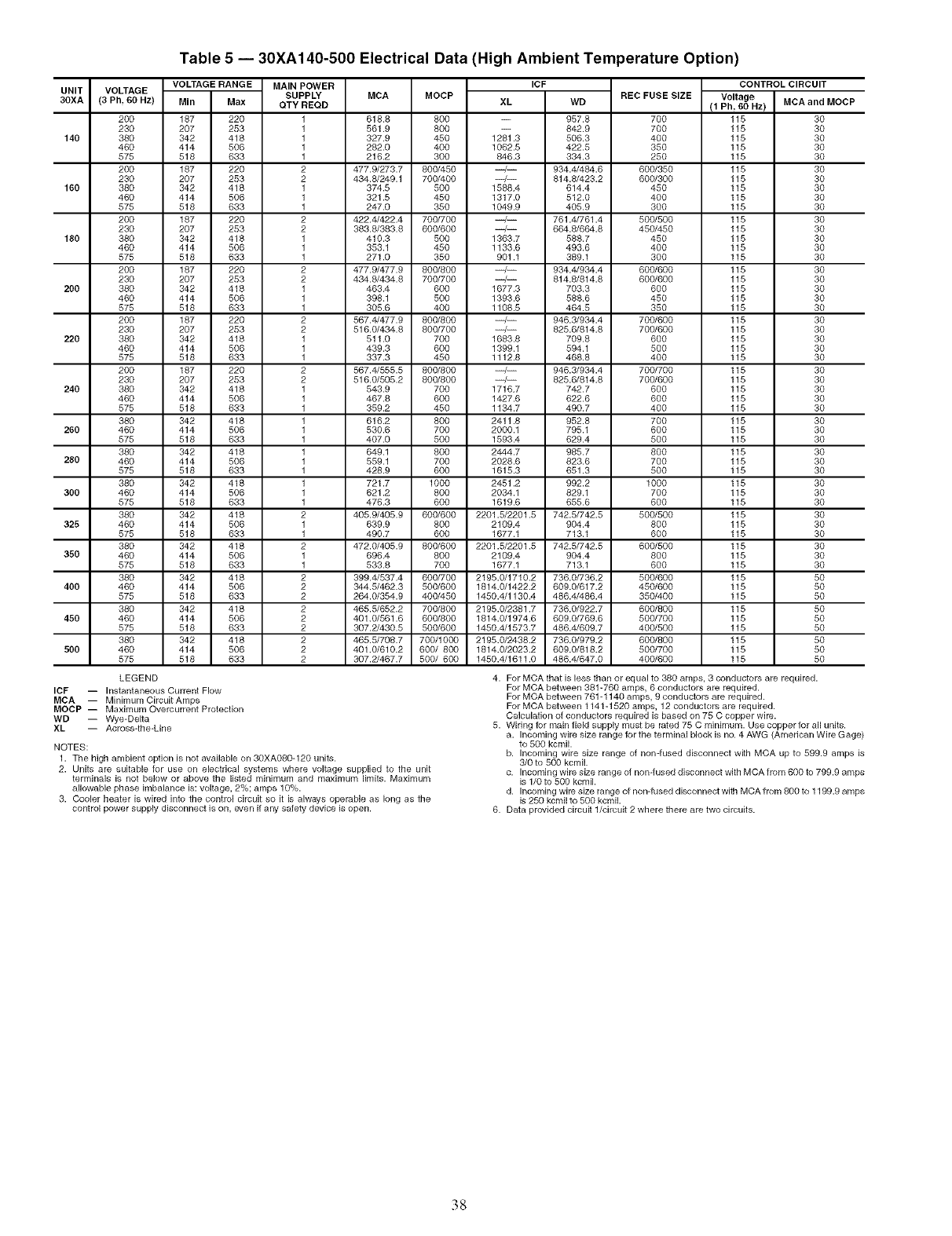
Table 5 -- 30XA140-500 Electrical Data (High Ambient Temperature Option)
UNIT
30XA
140
160
180
200
220
240
260
280
300
325
350
400
450
500
VOLTAGE RANGE MAIN POWER
VOLTAGE SUPPLY
(3 Ph, 60 Hz) MIn Max GTY REQD
200 187 220 1
230 207 263 1
380 342 418 1
460 414 506 1
575 518 633 1
200 187 220 2
230 207 263 2
380 342 418 1
460 414 506 1
575 518 633 1
200 187 220 2
230 207 263 2
380 342 418 1
460 414 506 1
575 518 633 1
200 187 220 2
230 207 263 2
380 342 418 1
460 414 506 1
575 518 633 1
200 187 220 2
230 207 263 2
380 342 418 1
460 414 506 1
575 518 633 1
200 187 220 2
230 207 263 2
380 342 418 1
460 414 506 1
575 518 633 1
380 342 418 1
460 414 506 1
575 518 633 1
380 342 418 1
460 414 506 1
575 518 633 1
380 342 418 1
460 414 506 1
575 518 633 1
380 342 418 2
460 414 506 1
575 518 633 1
380 342 418 2
460 414 506 1
575 518 633 1
380 342 418 2
460 414 506 2
575 518 633 2
380 342 418 2
460 414 606 2
575 518 633 2
380 342 418 2
460 414 506 2
575 518 633 2
MCA MOCP XL
618.8 800 --
561.9 800
327.9 450 12_.3
282.0 400 1062.5
216.2 300 846.3
477.9/273.7 800/450 --/--
434.8/249.1 760/406 --/--
374.5 500 1588.4
321.5 450 1317.0
247.0 350 1049.9
422.4/422.4 760/700 --/--
383.8/383.8 660/600 --/--
416.3 500 1363.7
353.1 450 1133.6
271.0 350 901.1
477.9/477.9 800/800 --/--
434.8/434.8 760/706 --/--
463.4 600 1677.3
398.1 500 1393.6
305.6 400 1108.5
567.4/477.9 800/860 --/--
516.0/434.8 800/700 --/--
511.0 700 1683.8
439.3 600 1399.1
337.3 450 1112.8
567.4/555.5 800/800 --/--
516.0/505.2 800/800 --/--
543.9 700 1716.7
467.8 600 1427.6
359.2 450 1134.7
616.2 800 2411.8
530.6 700 2000.1
407.0 500 1593.4
649.1 800 2444.7
559.1 700 2028.6
428.9 600 1615.3
721.7 1000 2451.2
621.2 800 2034.1
476.3 600 1619.6
405.9/406.9 600/600 2201.5/2201.5
639.9 800 2109.4
496.7 600 1677.1
472.0/405.9 860/600 2201.5/2201.5
696.4 800 2109.4
533.8 700 1677.1
399.4/537.4 660/700 2195.0/1710.2
344.5/462.3 500/600 1814.0/1422.2
264.0/354.9 400/450 1450.4/1130.4
465.5/652.2 760/800 2195.0/2381.7
401.0/561.6 660/800 1814.0/1974.6
307.2/430.5 560/600 1456.4/1573.7
465.6/706.7 700/1000 2195.0/2438.2
401.0/610.2 600/ 800 1814.0/2023.2
307.2/467.7 500/ 600 1450.4/1611.0
ICF
WD
957.8
842.9
506.3
422.5
334.3
934.4/484.6
614.8/423.2
614.4
512.0
405.9
761.4/761.4
664.6/664.8
588.7
493.6
389.1
934.4/934.4
614.6/814.8
703.3
588.6
464.5
946.8/934.4
625.6/814.8
709.8
694.1
468.8
946.8/934.4
625.6/814.8
742.7
622.6
490.7
952.8
795.1
629.4
985.7
823.6
651.3
992.2
829.1
655.6
742.6/742.5
904.4
713.1
742.6/742.5
904.4
713.1
736.0/736.2
609.0/617.2
486.4/486.4
736.0/922.7
609.6/769.6
486.4/609.7
736.0/979.2
609.0/818.2
486.4/647.0
REC FUSE SIZE
700
700
400
350
250
600/350
600/300
45O
400
300
500/500
450/450
45O
4OO
3OO
600/600
600/600
6OO
45O
35O
700/600
700/600
6OO
5OO
4OO
700/700
700/600
6OO
6OO
4OO
7OO
6OO
5OO
86O
7OO
5OO
1000
7OO
6OO
500/500
8OO
6OO
600/500
8OO
6OO
500/600
450/600
350/400
600/600
600/700
400/500
600/600
500/700
400/600
CONTROL CIRCUIT
Voltage MCA and MOCP
(1 Ph, 60 Hz)
115 30
115 30
115 30
115 30
115 30
115 30
115 30
115 30
115 30
115 30
115 30
115 30
115 30
115 30
115 30
115 30
115 30
115 30
115 30
115 30
115 30
115 30
115 30
115 30
115 30
115 30
115 30
115 30
115 30
115 30
115 30
115 30
115 30
115 30
115 30
115 30
115 30
115 30
115 30
115 30
115 30
115 30
115 30
115 30
115 30
115 50
115 50
115 50
115 50
115 50
115 50
115 50
115 50
115 50
LEGEND
ICF -- Instantaneous Current Flow
MCA -- Minimum Circuit Amps
MOCP -- Maximum Overcurrent Protection
WD -- Wye-Delta
XL -- Across-the-Line
NOTES:
1. The high ambient option is not available on 30XA080-126 units.
2. Units are suitable for use on electrical systems where voltage supplied to the unit
terminals is not below or above the listed minir'_lum and maximum limits. Maximum
allowable phase ir'_lbalance is: voltage, 2%; amps 10%.
3. Cooler heater is wired into the control circuit so it is always operable as long as the
control power supply disconnect is on, even if any safety device is open.
4. For MCA that is less than or equal to 380 amps, 3 conductors are required.
For MCA between 381-766 amps, 6 conductors are required.
For MCA between 761 -1140 amps, 9 conductors are required.
For MCA between 1141-1520 amps, 12 conductors are required.
Calculation o1 conductors required is based on 75 C copper wire.
5. Wiring for r'_lainfield supply r'_lustbe rated 75 C minirnur'_l. Use copper for all units.
a. Incor'_ling wire size range for the terminal block is no. 4 AWG (American Wire Gage)
to 500 kcrniL
b. Incoming wire size range of non-fused disconnect with MCA up to 599.9 arnps is
3/0 to 500 kcmiL
c. Incoming wire size range of non-fused disconnect with MCA from 600 k) 799.9 arnps
is 1/0 to 500 kcmiL
d. Incoming wire size range of non-fused disconnect with MCA from 600 to 1199.9 amps
is 250 kcrnil to 500 kcmil.
6. Data priwided circuit I/circuit 2 where there are two circuits.
38
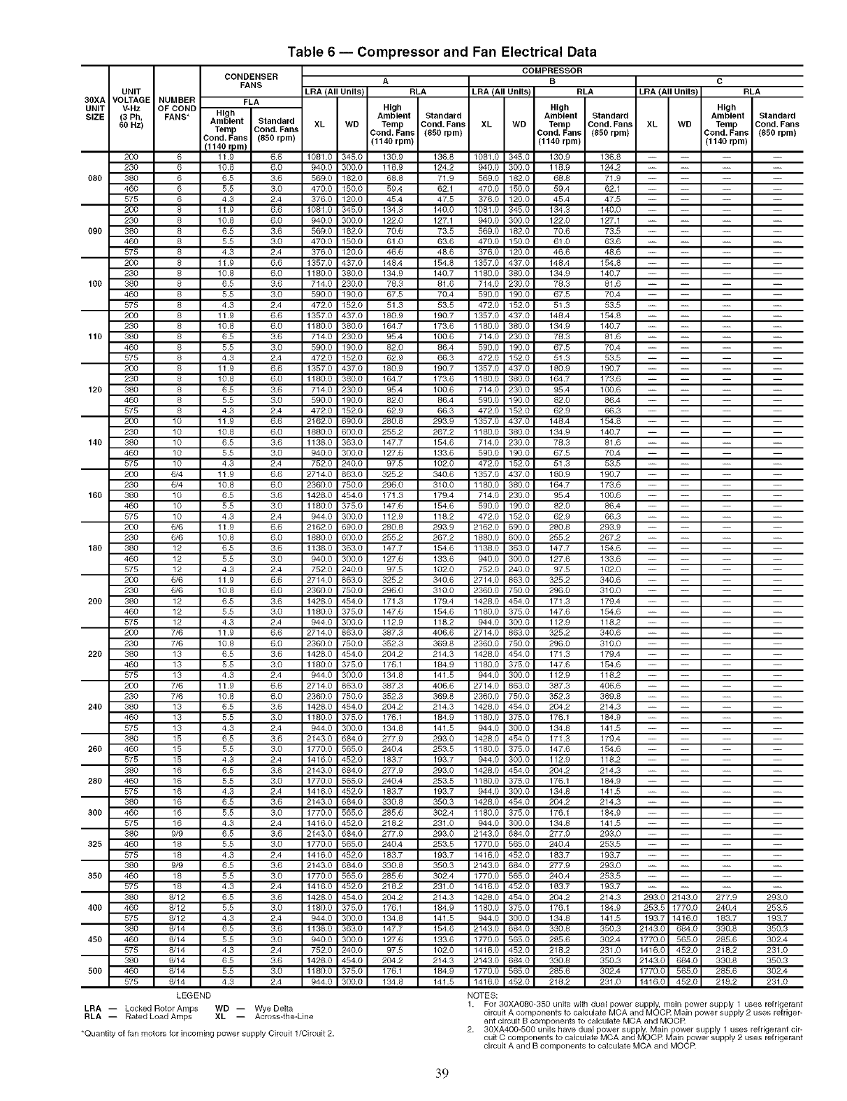
Table 6 -- Compressor and Fan Electrical Data
COMPRESSOR
A
LRA (All Units) RLA LRA (All Units)
High
Ambient Standard
XL WD Temp Cond. Fans XL WD
Cond. Fans (880 rpm)
(1140 rpm)
1081.0 345.0 130.9 136.8 1081.0 345.0
940.0 300.0 118.9 124.2 940.0 300.0
569.0 182.0 68.8 71.9 569.0 182.0
470.0 150.0 59.4 62.1 470.0 150.0
376.0 120.0 45.4 47.5 376.0 120.0
1081.0 345.0 134.3 140.0 1081.0 345.0
940.0 300.0 122.0 127.1 940.0 300.0
569.0 182.0 70.6 73.5 569.0 182.0
470.0 150.0 61.0 63.6 470.0 150.0
376.0 120.0 46.6 48.6 376.0 120.0
1357.0 437.0 148.4 154.8 1357.0 437.0
1180.0 380.0 134.9 140.7 1180.0 380.0
714.0 230.0 78.3 81.6 714.0 230.0
590.0 190.0 67.5 70.4 590.0 190.0
472.0 152.0 51.3 53.5 472.0 152.0
1357.0 437.0 180.9 190.7 1357.0 437.0
1180.0 380.0 164.7 173.6 1180.0 380.0
714.0 230.0 95.4 100.6 714.0 230.0
590.0 190.0 82.0 86.4 590.0 190.0
472.0 152.0 62.9 66.3 472.0 152.0
1357.0 437.0 180.9 190.7 1357.0 437.0
1180.0 380.0 164.7 173.6 1180.0 380.0
714.0 230.0 95.4 100.6 714.0 230.0
590.0 190.0 82.0 86.4 590.0 190.0
472.0 152.0 62.9 66.3 472.0 152.0
2162.0 690.0 280.8 293.9 1357.0 437.0
1880.0 600.0 255.2 267.2 1180.0 380.0
1138.0 363.0 147.7 154.6 714.0 230.0
940.0 300.0 127.6 133.6 590.0 190.0
752.0 240.0 97.5 102.0 472.0 152.0
2714.0 863.0 325.2 340.6 1357.0 437.0
2360.0 750.0 296.0 310.0 1180.0 380.0
1428.0 454.0 171.3 179.4 714.0 230.0
1180.0 375.0 147.6 154.6 590.0 190.0
944.0 300.0 112.9 118.2 472.0 152.0
2162.0 690.0 280.8 293.9 2162.0 690.0
1880.0 600.0 255.2 267.2 1880.0 600.0
1138.0 363.0 147.7 154.6 1138.0 363.0
940.0 300.0 127.6 133.6 940.0 300.0
752.0 240.0 97.5 102.0 752.0 240.0
2714.0 863.0 325.2 340.6 2714.0 863.0
2360.0 750.0 296.0 310.0 2360.0 750.0
1428.0 454.0 171.3 179.4 1428.0 454.0
1180.0 375.0 147.6 154.6 1180.0 375.0
944.0 300.0 112.9 118.2 944.0 300.0
2714.0 863.0 387.3 406.6 2714.0 863.0
2360.0 750.0 352.3 369.8 2360.0 750.0
1428.0 454.0 204.2 214.3 1428.0 454.0
1180.0 375.0 176.1 184.9 1180.0 375.0
944.0 300.0 134.8 141.5 944.0 300.0
2714.0 863.0 387.3 406.6 2714.0 863.0
2360.0 750.0 352.3 369.8 2360.0 750.0
1428.0 454.0 204.2 214.3 1428.0 454.0
1180.0 375.0 176.1 184.9 1180.0 375.0
944.0 300.0 134.8 141.5 944.0 300.0
2143.0 684.0 277.9 293.0 1428.0 454.0
1770.0 565.0 240.4 253.5 1180.0 375.0
1416.0 452.0 183.7 193.7 944.0 300.0
2143.0 684.0 277.9 293.0 1428.0 454.0
1770.0 565.0 240.4 253.5 1180.0 375.0
1416.0 452.0 183.7 193.7 944.0 300.0
2143.0 684.0 330.8 350.3 1428.0 454.0
1770.0 565.0 285.6 302.4 1180.0 375.0
1416.0 452.0 218.2 231.0 944.0 300.0
2143.0 684.0 277.9 293.0 2143.0 684.0
1770.0 565.0 240.4 253.5 1770.0 565.0
1416.0 452.0 183.7 193.7 1416.0 452.0
2143.0 684.0 330.8 350.3 2148.0 684.0
1770.0 565.0 285.6 302.4 1770.0 565.0
1416.0 452.0 218.2 231.0 1416.0 452.0
1428.0 454.0 204.2 214.3 1428.0 454.0
1180.0 375.0 176.1 184.9 1180.0 375.0
944.0 300.0 134.8 141.5 944.0 300.0
1138.0 363.0 147.7 154.6 2143.0 684.0
940.0 300.0 127.6 133.6 1770.0 565.0
752.0 240.0 97.5 102.0 1416.0 452.0
1428.0 454.0 204.2 214.3 2148.0 684.0
1180.0 375.0 176.1 184.9 1770.0 565.0
944.0 300.0 134.8 141.5 1416.0 452.0
NOTES:
CONDENSER
FANS
UNIT
30XA VOLTAGE NUMBER FLA
UNIT V-Hz OF COND High
SIZE (3 Ph, FANS* Ambient Standard
60 Hz) Temp Dond. Fans
Cond. Fans (080 rpm)
!1140 rpm !
200 6 11.9 6.6
230 6 10.8 6.0
080 380 6 6.5 3.6
460 6 5.5 3.0
575 6 4.3 2.4
200 8 11.9 6.6
230 8 10.8 6.0
090 380 8 6.5 3.6
460 8 5.5 3.0
575 8 4.3 2.4
200 8 11.9 6.6
230 8 10.8 6.0
100 380 8 6.5 3.6
460 8 5.5 3.0
575 8 4.3 2.4
200 8 11.9 6.6
230 8 10.8 6.0
110 380 8 6.5 3.6
460 8 5.5 3.0
575 8 4.3 2.4
200 8 11.9 6.6
230 8 10.8 6.0
120 380 8 6.5 3.6
460 8 5.5 3.0
575 8 4.3 2.4
200 10 11.9 6.6
230 10 10.8 6.0
140 380 10 6.5 3.6
460 10 5.5 3.0
575 10 4.3 2.4
200 6/4 11.9 6.6
230 6/4 10.8 6.0
160 380 10 6.5 3.6
460 10 5.5 3.0
575 10 4.3 2.4
200 6/6 11.9 6.6
230 6/6 10.8 6.0
180 380 12 6.5 3.6
460 12 5.5 3.0
575 12 4.3 2.4
200 6/6 11.9 6.6
230 6/6 10.8 6.0
200 380 12 6.5 3.6
460 12 5.5 3.0
575 12 4.3 2.4
200 7/6 11.9 6.6
230 7/6 10.8 6.0
220 380 13 6.5 3.6
460 13 5.5 3.0
575 13 4.3 2.4
200 7/6 11.9 6.6
230 7/6 10.8 6.0
240 380 13 6.5 3.6
460 13 5.5 3.0
575 13 4.3 2.4
380 15 6.5 3.6
260 460 15 5.5 3.0
575 15 4.3 2.4
380 16 6.5 3.6
280 460 16 5.5 3.0
575 16 4.3 2.4
380 16 6.5 3.6
300 460 16 5.5 3.0
575 16 4.3 2.4
380 9/9 6.5 3.6
328 460 18 5.5 3.0
575 18 4.3 2.4
380 9/9 6.5 3.6
380 460 18 5.5 3.0
575 18 4.3 2.4
380 8/12 6.5 3.6
400 460 8/12 5.5 3.0
575 8/12 4.3 2.4
380 8/14 6.5 3.6
480 460 8/14 5.5 3.0
575 8/14 4.3 2.4
380 8/14 6.5 3.6
800 460 8/14 5.5 3.0
575 8/14 4.3 2.4
LEGEND
LRA -- Locked Rotor Amps WD -- Wye Delta
XL Across-the-LineRLA -- Rated Load Amps
*Quantity of fan motors for incoming power supply Circuit 1/Circu9 2.
B C
RLA LRA (All Units) RLA
High High
Ambient Standard Ambient Standard
Temp Cond. Fans XL WD Temp Cond. Fans
Cond. Fans (850 rpm) Cond. Fans (080 rpm)
(1140 rpm) (1140 rpm)
130.9 136.8 ....
118.9 124.2 ....
68.8 71.9 ....
59.4 62.1 ....
45.4 47.5 ....
134.3 140.0 ....
122.0 127.1 ....
70.6 78.5 ....
61.0 63.6 ....
46.6 48.6 ....
148.4 154.8 ....
134.9 140.7 ....
78.8 81,6 ....
67.5 70.4 ....
51.3 53.5 ....
148.4 154.8 ....
134.9 140.7 ....
78.8 81,6 ....
67.5 70.4 ....
51.3 53.5 ....
180.9 190.7 ....
164.7 173.6 ....
95.4 100.6 ....
82.0 86.4 ....
62.9 66.3 ....
148.4 154.8 ....
134.9 140.7 ....
78.8 81,6 ....
67.5 70.4 ....
51.3 53.5 ....
180.9 190.7 ....
164.7 173.6 ....
95.4 100.6 ....
82.0 86.4 ....
62.9 66.3 ....
280.8 293.9 ....
255.2 267.2 ....
147.7 154.6 ....
127.6 138.6 ....
97.6 102.0 ....
325.2 340.6 ....
296.0 310.0 ....
171.3 179.4 ....
147.6 154.6 ....
112.9 118.2 ....
325.2 340.6 ....
296.0 310.0 ....
171.3 179.4 ....
147.6 154.6 ....
112.9 118.2 ....
387.3 406.6 ....
352.3 369.8 ....
204.2 214.3 ....
176.1 184.9 ....
134.8 141.5 ....
171.3 179.4 ....
147.6 154.6 ....
112.9 118.2 ....
204.2 214.3 ....
176.1 184.9 ....
134.8 141.5 ....
204.2 214.3 ....
176.1 184.9 ....
134.8 141.5 ....
277.9 293.0 ....
240.4 253.5 ....
183.7 193.7 ....
277.9 293.0 ....
240.4 253.5 ....
183.7 193.7 ....
204.2 214.3 293.0 2143.0 277.9 293.0
176.1 184.9 253.5 1770.0 240.4 253.5
134.8 141.5 193.7 1416.0 183.7 193.7
330.8 350.3 2143.0 684.0 330.8 350.3
285.6 302.4 1770.0 565.0 285.6 302.4
218.2 231.0 1416.0 452.0 218.2 231.0
330.8 350.3 2143.0 684.0 330.8 350.3
285.6 302.4 1770.0 565.0 285.6 302.4
218.2 231.0 1416.0 452.0 218.2 231.0
1. For 30XA080-350 units with dual power supply, main power supply 1 uses refrigerant
circuit A components to calculate MCA and MOOR Main power supply 2 uses refriger-
ant circuit B components to calculate MCA and MOOR
2. 30XA400-500 units have dual power supplely..Main power supply 1 uses refrigerant cir-
cuit C components to calculate MCA and MOOR Main power supply 2 uses refrigerant
circuit A and B components to calculate MCA and MOOR
39
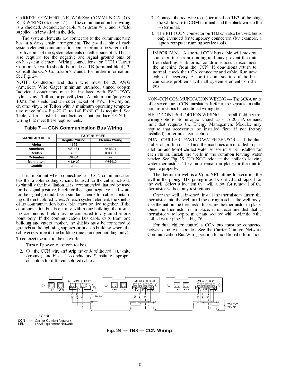
CARRIER COMFORT NETWORK@ COMMUNICATION
BUS WIRING (See Fig. 24) -- The communication bus wiring
is a shielded, 3-conductor cable wifll &'ain wire and is field
supplied and instCdled in the field.
The system elements tue connected to the communication
bus in a &fisy chain arrangement. The positive pin of each
system element communication connector must be wired to the
positive pins of the system elements on either side of it. This is
also required for the negative and signal ground pins of
each system element. Winng connections for CCN (Carrier
Comfort Network) should be made at TB (terminal block) 3.
Consult the CCN Contractor's Manual for further information.
See Fig. 24.
NOTE: Conductors and &'ain wire must be 20 AWG
(American Wire Gage) minimum stranded, tinned coppel:
Individual conductors must be insulated with PVC, PVC/
nylon, vinyl, Teflon, or polyethylene. An aluminum/polyester
100% foil shield and an outer jacket of PVC, PVC/nylon,
chrome vinyl, or Teflon with a minimum opemfing tempera-
ture range of-4 F (-20 C) to 140 F (60 C) is required. See
Table 7 for a list of manufacturers that produce CCN bus
wiring that meet these requirements.
Table 7 -- CON Communication Bus Wiring
MANUFACTURER
Alpha
American
Belden
Columbia
Manhatten
Quabik
PART NUMBER
Regular Wiring Plenum Wiring
1895
A21451 A48301
8205 884421
D6451
M13402 M64430
6130
it is important when connecting to a CCN communication
bus that a color coding scheme be used for the entire network
to simplify the installation. It is recommended that red be used
for the signal positive, black for the signal negative, and white
for the signal ground. Use a similar scheme for cables contain-
ing different colored wires. At each system element, the shields
of its communication bus cables must be tied togethel: If the
communication bus is entirely within one building, the result-
ing continuous shield must be connected to a ground at one
point only. If the communication bus cable exits from one
building and enters another, the shields must be connected to
grounds at the lightning suppressor in each building where the
cable enters or exits the building (one point per building only).
To connect the unit to the network:
1. Turn off power to the control box.
2. Cut the CCN wire and strip the ends of the red (+), white
(ground), and black (-) conductors. Substitute appropri-
ate colors for different colored cables.
3. Connect the red wire to (+) terminal on TB3 of the plug,
the white wire to COM terminal, and the black wire to the
(-) terminal.
4. The RJI 4 CCN connector on TB3 can also be used, but is
only intended for temporary connection (for example, a
laptop computer running service tool).
IMPORTANT: A shorted CCN bus cable will prevent
some routines from running and may prevent the unit
from starting. If abnormal conditions occur, disconnect
the machine from the CCN. If conditions return to
normal, check the CCN connector and cable. Run new
cable if necessary. A short in one section of the bus
can cause problems with all system elements on the
bus.
NON-CCN COMMUNICATION WIRING -- The 30XA units
offer severtd non-CCN translatoL's. Refer to the separate installa-
tion instructions for additional wiring steps.
FIELD CONTROL OPTION WIRING -- Install field control
wiring options. Some options, such as 4 to 20 mA demand
limit that requires the Energy Management Module, may
require that accessories be installed first (if not factory
installed) for terminal connections.
DUAL CHILLER LEAVING WATER SENSOR --If the dual
chiller algorithm is used and the machines are installed in par-
allel, an additional chilled water sensor must be installed for
each chillec Install the wells in the common leaving water
header See Fig 25. DO NOT relocate the chiller's leaving
water thermistoLs. They must remain in place for the unit to
operate properly.
The thermistor well is a 1/4 in. NPT fitting for securing the
well in the piping. The piping must be drilled and tapped for
the well. Select a location that will allow for removal of the
thermistor without any restrictions.
Once the well is inserted, install the thermistors. Insert the
thermistor into the well until the o-ring reaches the well body.
Use the nut on the thermistor to secure the thermistor in place.
Once the thermistor is in place, it is recommended that a
thermistor wire loop be made and secured with a wire tie to the
chilled water pipe. See Fig. 26.
For dual chiller control a CCN bus must be connected
between the two modules. See the Carrier Comfort Network
Communication Bus Wiring section for additional information.
--MZZZ3
o[21121
LEN CCN oE3E3
LEN CCN
LEGEND
CCN -- Carrier Comfort Network
LEN -- Local Equipment Network
Fig. 24 -- TB3 -- CON Wiring
TO NEXT
DEVICE
4O
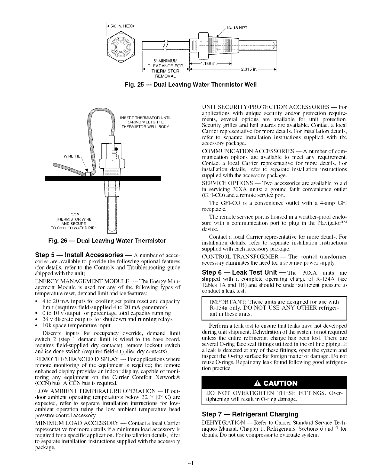
2.315 in._
REMOVAL
Fig. 25 -- Dual Leaving Water Thermistor Well
INSERT THERMISTOR UNTIL
O-RING MEETS THE
THERMISTOR WELL BODY.
WIRE TIE\ \
LOOP
THERMISTOR WIRE
AND SECURE
TO CHILLED WATER PIPE
Fig. 26 -- Dual Leaving Water Thermistor
Step 5 -- Install Accessories -- A number of acces-
soriesare available to provide the following optional features
(for details, refer to file Controls and Troubleshooting guide
shipped with the unit).
ENERGY MANAGEMENT MODULE -- The Energy Man-
agement Module is used for any of the following types of
temperatme reset, demand limit and ice features:
• 4 to 20 mA inputs for cooling set point reset and capacity
limit 0equires field-supplied 4 to 20 mA generator)
• 0 to 10 v output for percentage total capacity running
• 24 v discrete outputs for shutdown and running relays
• 10k space temperature input
Discrete inputs for occupancy override, demand limit
switch 2 (step 1 demand limit is wired to the base board,
requires field-supplied dry contacts), remote lockout switch
and ice done switch (requires field-supplied dlT contacts)
REMOTE ENHANCED DISPLAY -- For applications where
remote monitoring of the equipment is required; the remote
enhanced display provides an indoor display, capable of moni-
toring any equipment on the Carrier Comfort Network®
(CCN) bus. A CCN bus is required.
LOW AMBIENT TEMPERATURE OPERATION -- If out-
door ambient operating temperatures below 32 F (Oo C) are
expected, refer to separate installation instructions for low-
ambient operation using the low ambient temperature head
pressure control accessory.
M[NIMUM LOAD ACCESSORY -- Contact a loc_fl Carrier
representative for more details if a minimum load accessory is
required for a specific application. For installation details, refer
to sepm'ate inst_fllation instructions supplied with the accessory
package.
UNIT SECURITY/PROTECTION ACCESSORIES -- For
applications with unique security and/or protection require-
ments, several options are available for unit protection.
Security grilles and hail guards are available. Contact a local
Carrier representative for more details. For inst_fllation details,
refer to separate inst_dlation instructions supplied with the
accessory package.
COMMUNICATION ACCESSORIES -- A number of com-
munication options are available to meet any requirement.
Contact a local Carder representative for more details. For
installation details, refer to sep_u'ate installation instructions
supplied with the accessory package.
SERVICE OPTIONS -- Two accessories are available to aid
in servicing 30XA units: a ground fault convenience outlet
(GFI-CO) and a remote service port.
The GFI-CO is a convenience outlet with a 4-amp GFI
receptacle.
The remote service port is housed in a weather-proof enclo-
sure with a communication port to plug in the Navigato( TM
device.
Contact a local Carrier representative for more dettfils. For
installation details, refer to sepm'ate installation instructions
supplied with each accessory package.
CONTROL TRANSFORMER -- The control transformer
accessory eliminates the need for a separate power supply.
Step 6 -- Leak Test Unit -- The 30XA units are
shipped with a complete operating charge of R-134A (see
Tables IA and IB) and should be under sufficient pressure to
conduct a leak test.
IIMPORTANT: These units are designed for use with I
=
R-134a only. DO NOT USE ANY OTHER refriger- I
ant in these units.
Pedorm a leak test to ensure that leaks have not developed
during unit shipment. Dehydration of the system is not required
unless the entire refrigerant charge has been lost. There are
several O-ring face seal fittings utilized in the oil line piping. If
a leak is detected at any of these fittings, open the system and
inspect the O-ring sudace for foreign matter or damage. Do not
reuse O-rings. Repair any leak found following good lefrigera-
tion practice.
DO NOT OVERTIGHTEN THESE FITFINGS. Over-
tightening will result in O-ring dmnage.
Step 7 -- Refrigerant Charging
DEHYDRATION -- Refer to Carrier Standard Service Tech-
niques Manual, Chapter 1, Refrigerants, Sections 6 and 7 for
details. Do not use compressor to evacuate system.
41
REFRIGERANTCHARGE
IMPORTANT:Theseunitsm'edesignedfor usewith]
R-134a only. DO NOT USE ANY OTHER refrigerant in I
these units.
The liquid chmging method is recommended for complete
charging or when additional charge is required.
When charging, circulate water through the cooler at all
times to prevent freezing. Freezing damage is considered
abuse and may void the Carrier warranty.
DO NOT OVERCHARGE system. Overcharging results in
higher discharge pressure with higher cooling fluid con-
sumption, possible compressor damage, and higher power
consumption.
The 30XA units ale shipped fiom the factory with a full
chmge of R-134a. The unit should not need to be charged at
installation unless a leak was detected in Step 6 -- Leak Test
Unit section. If dehydration and recharging is necessmy, use
industry standard practices or refer to Carrier Standard Service
Techniques Manual as required.
42


Copyright 2005 Carrier Corporation
Manufacturer reserves the right to discontinue, or change at any time, specifications or designs without notice and without incurring obligations.
PC 903 Catalog No. 533-00068 Printed in U.S.A. Form 30XA-1SI Pg 44 6-05 Replaces: New
