CARRIER Package Units(both Units Combined) Manual L0522671
User Manual: CARRIER CARRIER Package Units(both units combined) Manual CARRIER Package Units(both units combined) Owner's Manual, CARRIER Package Units(both units combined) installation guides
Open the PDF directly: View PDF ![]() .
.
Page Count: 148 [warning: Documents this large are best viewed by clicking the View PDF Link!]
19X RV
Hermetic Centrifugal Liquid Chillers
with PIC III Controls
50/60 Hz
HFC-134a
Start-Up, Operation, and Maintenance Instructions
SAFETY CONSIDERATIONS
Centrifugal liquid chillers are designed to provide safe
and reliable service when operated within design speci-
fications. When operating this equipment, use good
judgment and safety precautions to avoid damage to
equipment and property or injury to personnel.
Be sure you understand and follow the procedures
and safety precautions contained in the chiller instruc-
tions as well as those listed in this guide.
DO NOT VENT refrigerant relief valves within a buikting. Outlet
from rupture disc or relief valve must be vented outdoors in accor-
dance with the latest edition of ANSI/ASHRAE 15 (American
National Standards Institute/American Society of Heating, Refrigera-
tion, and Air Conditioning Engineers). The accumulation of refriger-
ant in an enclosed space can displace oxygen and cause asphyxiation.
PROVIDE adequate ventilation in accordance with ANSI/ASHRAE
15, especially for enclosed and low overhead spaces. Inhalation of
high concentrations of vapor is hamlfill and may cause heart irregular-
ities, nnconsciousness, or death. Misuse can be fatal. Vapor is heavier
than air and rednces the amonnt of oxygen available for breathing.
Product causes eye and skin irritation. Decomposition products are
hazardous.
DO NOT USE OXYGEN to purge lines or to pressurize a chiller for
any purpose. Oxygen gas reacts violently with oil, grease, and other
COlnlllOn substances.
NEVER EXCEED specified test pressures, VERIFY the allowable
test pressure by checking the instruction literature and the design pres-
sures on the equipment nameplate.
DO NOT USE air for leak testing. Use only refrigerant or dry
nitrogen.
DO NOT VALVE OFF any safety device.
BE SURE that all pressure relief devices are properly installed and
fimctioning before operating any chiller.
THERE IS A RISK OF INJURY OR DEATH by electrocution. High
voltage may be present on the motor leads even though the motor is
not running. Open the power supply disconnect before touching
motor leads or terminals.
DO NOT WELD OR FLAMECUT any refrigerant line or vessel until
all refrigerant (liquM atM V'al)or) has been removed from chiller.
Traces of vapor should be displaced with dry air or nitrogen and the
work area should be well ventilated. R@'ixemm in contact _Hth an
o!)et_flame prodHc_,s toxic gaxes.
DO NOT USE eyebolts or eyebolt holes to rig chiller sections or the
entire assembly.
DO NOT work on high-voltage equipment unless yon are a qualified
electrician.
DO NOT WORK ON electrical components, including control
panels, switches, starters, or oil heater until you are sure ALL
POWER IS OFF and no residual voltage can leak from capacitors or
solid-state components.
LOCK OPEN AND TAG electrical circuits during servicing. IF
WORK IS INTERRUPTED, confirm that all circuits are deenergized
before resuming work.
AVOID SPILLING liquid refrigerant on skin or getting it into the
eyes. USE SAFETY GOGGLES. Wash any spills from the skin with
soap and water. If liqnid refrigerant enters the eyes, IMMEDIATELY
FLUSH EYES with water and consult a physician.
NEVER APPLY an open flame or live steam to a refrigerant cylinder.
Dangerous over pressure can result. When it is necessary to heat
refrigerant, use only warm (110 F D3 C]) water.
DO NOT REUSE disposable (nonreturnable) cylinders or attempt to
refill them. It is DANGEROUS AND ILLEGAL. When cylinder is
emptied, evacuate remaining gas pressure, loosen the collar and
unscrew and discard the valve stem. DO NOT INCINERATE.
CHECK THE REFRIGERANT TYPE before adding refrigerant to
the chiller. The introdnction of the wrong refrigerant can cause
damage or malfunction to this chiller.
Operation of this equipment with refrigerants other than those
cited herein should comply with ANSI/ASHRAE 15 (latest edition).
Contact Carrier for timber information on use of this chiller with other
refrigerants.
DO NOT ATTEMPT TO REMOVE fittings, covers, etc., while
chiller is under pressure or while chiller is running. Be sum pressure is
at 0 psig C0kPa) before breaking any refrigerant connection.
CAREFULLY INSPECT all relief devices, rupture discs, and other
relief devices AT LEAST ONCE A YEAR. If chiller operates in a
corrosive atmosphere, inspect the devices at morn frequent intervals.
DO NOT ATTEMPT TO REPAIR OR RECONDITION any relief
device when corrosion or build-up of foreign material (rust, dirt, scale,
etc.) is found within the valve body or mechanism. Replace the
device.
DO NOT install relief devices in series or backwards.
USE CARE when working near or in line with a compressed spring.
Sudden release of the spring can cause it and objects in its path to act
as projectiles.
DO NOT STEP on refrigerant lines. Broken lines can whip about and
release refrigerant, causing personal injury.
DO NOT climb over a chiller. Use platform, catwalk, or staging.
Follow safe practices when using ladders.
USE MECHANICAL EQUIPMENT (crone, hoist, etc.) to lilt
or move inspection covers or other heax.y components. Even if
components are light, use mechanical equipment when there is a risk
of slipping or losing your balance.
BE AWARE that certain automatic start arrangements CAN
ENGAGE THE STARTER, TOWER FAN, OR PUMPS. Open the
disconnect ahead of the starter, tower fans, or pumps.
USE only repair or replacement parts that meet the code requirements
of the original equipment.
DO NOT VENT OR DRAIN waterboxes containing industrial brines,
liquid, gases, or semisolids withont the permission of your process
control group.
DO NOT LOOSEN waterbox cover bolts until the waterbox has been
completely drained.
DO NOT LOOSEN a packing gland nut before checking that the nut
has a positive thread engagement.
PERIODICALLY INSPECT all valves, fittings, and piping for
corrosion, rest, leaks, or damage.
PROVIDE A DRAIN connection in the vent line near each pressure
relief device to prevent a build-up of condensate or rain watec
Manufacturer reserves the right to discontinue, or change at any time, specifications or designs without notice and without incurring obligations.
PC 211 Catalog No. 531-986 Printed in U.S.A. Form 19XRV-1SS Pg 1 4-05 Replaces: New
CONTENTS
Page
SAFETY CONSIDERATIONS ...................... 1
INTRODUCTION .................................. 4
ABBREVIATIONS AND EXPLANATIONS ........ 4,5
CHILLER FAMILIARIZATION .................... 5,6
Chiller Information Nameplate .................... 5
System Components ............................. 5
Cooler ............................................ 5
Condenser ....................................... 5
Motor-Compressor ............................... 5
Control Panel ..................................... 5
Variable Frequency Drive ......................... 5
Storage Vessel (Optional) ........................ 5
REFRIGERATION CYCLE ......................... 7
MOTOR AND LUBRICATING OIL
COOLING CYCLE .............................. 7
VFD COOLING CYCLE ............................ 8
LUBRICATION CYCLE .......................... 8,9
Summary ......................................... 8
Details ............................................ 8
Oil Reclaim System ............................... 8
• PRIMARY OIL RECOVERY MODE
• SECONDARY OIL RECOVERY METHOD
Bearings ......................................... 8
STARTING EQUIPMENT ....................... 9-ll
Unit-Mounted VFD ................................ 9
CONTROLS ................................... l 1-49
Definitions ...................................... l l
• ANALOG SIGNAL
• DISCRETE SIGNAL
General .......................................... 11
PIC III System Components ..................... ] ]
• INTERNATIONAL (;;HILLER VISUAL
CONTROLLER (ICVC)
•CHILLER CONTROL MODULE (CCM)
• OIL HEATER CONTACTOR (lC)
• OIL PUMP CONTACTOR (2C)
• HOT GAS BYPASS CONTACTOR RELAY (3C)
(Optional)
• CONTROL TRANSFORMERS (TI, T2)
• OPTIONAL TRANSFORMER (T3)
• SENSORS
• FLOW DETECTION
ICVC Operation and Menus ...................... 16
• GENERAL
• ALARMS AND ALERTS
• ICVC MENU ITEMS
• BASIC [CVC OPERATIONS (Using the Softkeys)
• TO VIEW STATUS
• FORCING OPERATIONS
• TIME SCHEDULE OPERATION
• TO VIEW AND CHANGE SET POINTS
• SERVICE OPERATION
PIC III System Functions ........................ 34
• CAPACITY CONTROL
• ECW CONTROL OPTION
• CONTROL POINT DEADBAND
• DIFFUSER CONTROL
• PROPORTIONAL BANDS AND GAIN
• DEMAND LIMITING
• CHILLER TIMERS AND STARTS COUNTER
• OCCUPANCY SCHEDULE
Safety Controls .................................. 36
Shunt Trip (Option) .............................. 36
Default Screen Freeze ........................... 36
Ramp Loading ................................... 39
Capacity Override ............................... 39
Page
High Discharge Temperature Control ............ 39
Oil Sump Temperature and Pump Control ....... 39
Oil Cooler ....................................... 39
Remote Start/Stop Controls ..................... 40
Spare Safety and Spare Temperature Inputs ..... 40
Alarm (Trip) Output Contacts .................... 40
Kilowatt Output .................................. 41
Remote Reset of Alarms ......................... 41
Condenser Pump Control ....................... 41
Condenser Freeze Prevention ................... 41
Evaporator Freeze Protection ................... 41
Tower Fan Relay Low and High .................. 41
Auto. Restart After Power Failure ................ 42
WaterlBrine Reset ............................... 42
• RESET TYPE 1: 4 TO 20 mA TEMPERATURE RESET
• RESET TYPE 2: REMOTE TEMPERATURE RESET
• RESET TYPE 3
Surge Prevention Algorithm ..................... 42
Surge Protection ................................ 43
Head Pressure Reference Output ................ 44
Lead/Lag Control ................................ 44
• COMMON POINT SENSOR USAGE AND
INSTALLATION
• CHILLER COMMUNICATION WIRING
• LEAD/LAG OPERATION
• FAULTED CHILLER OPERATION
• LOAD BALANCING
• AUTO. RESTART AFTER POWER FAILURE
Ice Build Control ................................ 46
• ICE BUILD INITIATION
• START-UP/RECYCLE OPERATION
• TEMPERATURE CONTROL DURING ICE BUILD
• TERMINATION OF ICE BUILD
• RETURN TO NON-ICE BUILD OPERATIONS
Attach to Network Device Control ............... 47
• ATTACHING TO OTHER CCN MODULES
Service Operation ............................... 48
• TO ACCESS THE SERVICE SCREENS
• TO LOG OUT OF NETWORK DEVICE
• TIME BROADCAST ENABLE
• HOLIDAY SCHEDULING
• DAYLIGHT SAVING TIME CONFIGURATION
START-U P/SH UTDOWN/R ECYCLE
SEQUENCE ................................ 50-52
Local Start-Up ................................... 50
Shutdown Sequence ............................ 51
Automatic Soft Stop Amps Threshold ........... 51
Chilled Water Recycle Mode ..................... 51
Safety Shutdown ................................ 52
BEFORE INITIAL START-UP .................. 52-67
Job Data Required .............................. 52
Equipment Required ............................ 52
Using the Optional Storage Tank
and Pumpout System ......................... 52
Remove Shipping Packaging .................... 52
Open Oil Circuit Valves .......................... 52
Oil Charge ....................................... 52
Tighten All Gasketed Joints and
Guide Vane Shaft Packing ..................... 52
Check Chiller Tightness ......................... 53
Refrigerant Tracer ............................... 53
Leak Test Chiller ................................ 55
Standing Vacuum Test ........................... 55
Chiller Dehydration .............................. 58
Inspect Water Piping ............................ 58
Check Optional Pumpout Compressor
Water Piping .................................. 58
CONTENTS
Page
Check Relief Valves ............................. 58
Identify the VFD ................................. 58
Input Power Wiring .............................. 59
Checking the Installation ........................ 59
Inspect Wiring ................................... 60
Ground Fault Troubleshooting .................. 60
Carrier Comfort Network Interface ............... 60
Power Up the Controls and
Check the Oil Heater .......................... 61
• SOFTWARE VERSION
Software Configuration ......................... 61
Input the Design Set Points ..................... 61
Input the Local Occupied Schedule
(OCCPC01S) .................................. 61
Input Service Configurations .................... 61
• PASSWORD
• INPUT TIME AND DATE
• CHANGE ICVC CONFIGURATION
IF NECESSARY
• TO CHANGE THE PASSWORD
• TO CHANGE THE ICVC DISPLAY FROM
ENGLISH TO METRIC UNITS
• CHANGE LANGUAGE
• MODIFY CONTROLLER IDENTIFICATION
IF NECESSARY
• INPUT EQUIPMENT SERVICE PARAMETERS
IF NECESSARY
• VERIFY VFD CONFIGURATION AND CHANGE
PARAMETERS IF NECESSARY
• VFD CHILLER FIELD SET UP AND VERIFICATION
• CONFIGURE DIFFUSER CONTROL IF
NECESSARY
• MODIFY EQUIPMENT CONFIGURATION
IF NECESSARY
Perform a Control Test .......................... 64
• PRESSURE TRANSDUCER CALIBRATION
Check Optional Pumpout System
Controls and Compressor ..................... 65
High Altitude Locations ......................... 65
Charge Refrigerant Into Chiller .................. 65
• CHILLER EQUALIZATION WITHOUT A
PUMPOUT UNIT
•CHILLER EQUALIZATION WITH
PUMPOUT UNIT
• TRIMMING REFRIGERANT CHARGE
INITIAL START-UP ............................. 67,68
Preparation ..................................... 67
Check Motor Rotation ........................... 67
Check Oil Pressure and Compressor Stop ...... 67
To Prevent Accidental Start-Up .................. 67
Check Chiller Operating Condition .............. 68
Instruct the Customer Operator ................. 68
•COOLER-CONDENSER
• OPTIONAL PUMPOUT STORAGE TANK AND
PUMPOUT SYSTEM
• MOTOR COMPRESSOR ASSEMBLY
• MOTOR COMPRESSOR LUBRICATION SYSTEM
•CONTROL SYSTEM
• AUXILIARY EQUIPMENT
• DESCRIBE CHILLER CYCLES
• REVIEW MAINTENANCE
• SAFETY DEVICES AND PROCEDURES
• CHECK OPERATOR KNOWLEDGE
• REVIEW THE START-UR OPERATION, AND
MAINTENANCE MANUAL
(cont)
Page
OPERATING INSTRUCTIONS ................. 68-70
Operator Duties ................................. 68
Prepare the Chiller for Start-Up ................. 68
To Start the Chiller .............................. 68
Check the Running System ..................... 68
To Stop the Chiller .............................. 69
After Limited Shutdown ......................... 69
Preparation for Extended Shutdown ............ 69
After Extended Shutdown ....................... 69
Cold Weather Operation ......................... 69
Manual Guide Vane Operation ................... 69
Refrigeration Log ............................... 69
PUMPOUT AND REFRIGERANT TRANSFER
PROCEDURES ............................. 71-74
Preparation ..................................... 71
Operating the Optional Pumpout Unit ........... 71
•TO READ REFRIGERANT PRESSURES
• POSITIVE PRESSURE CHILLERS WITH
STORAGE TANKS
• CHILLERS WITH ISOLATION VALVES
• DISTILLING THE REFRIGERANT
GENERAL MAINTENANCE .................... 74,75
Refrigerant Properties .......................... 74
Adding Refrigerant .............................. 74
Removing Refrigerant ........................... 74
Adjusting the Refrigerant Charge ............... 74
Refrigerant Leak Testing ........................ 74
Leak Rate ....................................... 74
Test After Service, Repair, or Major Leak ........ 74
• TESTING WITH REFRIGERANT TRACER
• TESTING WITHOUT REFRIGERANT TRACER
• TO PRESSURIZE WITH DRY NITROGEN
Repair the Leak, Retest, and Apply
Standing Vacuum Test ........................ 75
Checking Guide Vane Linkage .................. 75
Trim Refrigerant Charge ......................... 75
WEEKLY MAINTENANCE ........................ 75
Check the Lubrication System .................. 75
SCHEDULED MAINTENANCE ................ 75-78
Service Ontime .................................. 75
Inspect the Control Panel ....................... 76
Check Safety and Operating Controls
Monthly ....................................... 76
Changing Oil Filter .............................. 76
Oil Specification ................................ 76
Oil Changes ..................................... 76
• TO CHANGE THE OIL
Refrigerant Filter ................................ 76
Oil Reclaim Filter ................................ 76
VFD Refrigerant Strainer ........................ 77
Inspect Refrigerant Float System ............... 77
Inspect Relief Valves and Piping ................ 77
Compressor Bearing and Gear
Maintenance .................................. 77
Inspect the Heat Exchanger Tubes
and Flow Devices ............................. 77
• COOLER AND OPTIONAL FLOW DEVICES
• CONDENSER AND OPTIONAL FLOW DEVICES
Water Leaks ..................................... 77
Water Treatment ................................. 78
Inspect the VFD ................................. 78
Recalibrate Pressure Transducers .............. 78
CONTENTS (cont)
Page
Optional Pumpout System Maintenance ......... 78
• OPTIONAL PUMPOUT COMPRESSOR OIL
CHARGE
• OPTIONAL PUMPOUT SAFETY CONTROL
SETTINGS
Ordering Replacement Chiller Parts ............. 78
TROUBLESHOOTING GUIDE ................ 79-I 26
Overview ........................................ 79
Checking Display Messages ..................... 79
Checking Temperature Sensors ................. 79
• RESISTANCE CHECK
• VOLTAGE DROP
•CHECK SENSOR ACCURACY
• DUAL TEMPERATURE SENSORS
Checking Pressure Transducers ................. 79
• COOLER CONDENSER PRESSURE TRANSDUCER
AND OPTIONAL WATERSIDE FLOW DEVICE
CALIBRATION
• TRANSDUCER REPLACEMENT
Control Algorithms Checkout Procedure ........ 80
Control Test ..................................... 81
Control Modules ................................. 97
•RED LED (Labeled as STAT)
• GREEN LED (Labeled as COM)
Notes on Module Operation ..................... 97
Chiller Control Module (CCM) ................... 97
• INPUTS
• OUTPUTS
Replacing Defective Processor Modules ........ 98
• INSTALLATION
Gateway Status LEDs ........................... 99
• DRIVE STATUS INDICATOR
• MS STATUS INDICATOR
• NET A STATUS INDICATOR
• NET B STATUS INDICATOR
Physical Data ................................... 100
APPENDIX -- 19XRV LIQUlFLO TM 2 ICVC
PARAMETER INDEX ...................... 127-135
INDEX .......................................... 136
INITIAL START-UP CHECKLIST FOR
19XRV HERMETIC CENTRIFUGAL
LIQUID CHILLER .................... CL-I to CL-12
INTRODUCTION
Prior to initial start-up of the 19XRV unit, those involved in
the stall-up, operation, and maintenance should be thoroughly
familiar with these instructions and other necessary job data.
This book is outlined to fmnili;uize those involved in the
stmt-up, operation and maintenance of the unit with the control
system before performing stmt-up procedures. Procedures in
this manual ;ue arranged in the sequence required for proper
chiller start-up and operation.
This unit uses a microprocessor control system. Do not
shol_t or jumper between terminations on circuit bo;uds or
modules; control or board failure may result.
Be aware of electrostatic discharge (static electricity) when
handling or making contact with circuit boards or module
connections. Always touch a chassis (grounded) part to
dissipate body electrostatic charge before working inside
control centel:
Use extreme c;ue when handling tools near bo;uds and
when connecting or disconnecting terminal plugs. Circuit
boards can easily be &_maged. Always hold boards by the
edges and avoid touching components and connections.
This equipment uses, and can radiate, radio frequency
energy. If not installed and used in accor&mce with the
instruction manu;fl, it may cause interference to radio
communications. It has been tested and found to comply
with the limits for a Class A computing device pursuant to
Subpart J of Pall 15 of FCC Rules, which are designed to
provide reasonable protection against such interference
when operated in a commercial environment. Operation of
this equipment in a residential area is likely to cause
interference, in which case the usel: at his own expense,
will be required to take whatever measures may be
required to correct the interference.
Always store and transport replacement or defective boards
in anti-static shipping bag.
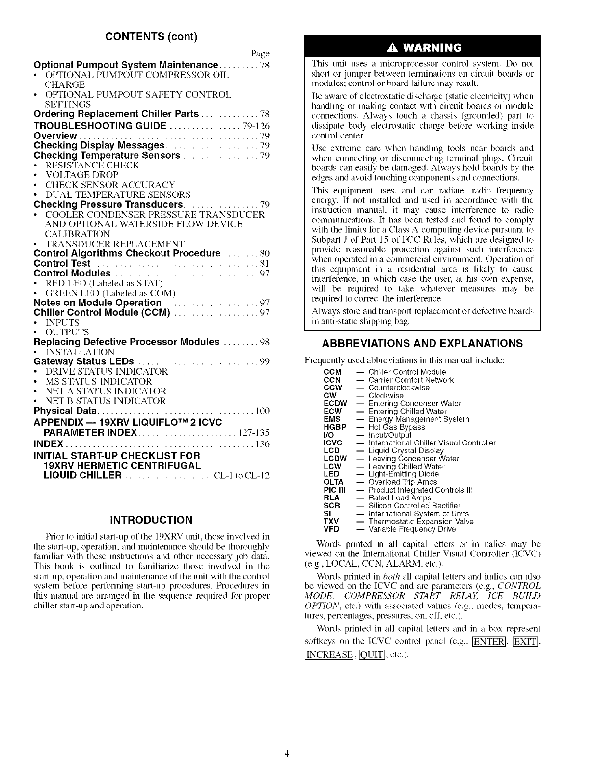
ABBREVIATIONS AND EXPLANATIONS
Frequently used abbreviations in this manual include:
CCM -- Chiller Control Module
CCN
CCW
CW
ECDW
ECW
EMS
HGBP
I/O
ICVC
LCD
LCDW
LCW
LED
OLTA
PIC III
RLA
SCR
Sl
TXV
VFD
-- Carrier Comfort Network
-- Counterclockwise
-- Clockwise
-- Entering Condenser Water
-- Entering Chilled Water
-- Energy Management System
-- Het Gas Bypass
-- Input/Output
-- International Chiller Visual Controller
-- Liquid Crystal Display
-- Leaving Condenser Water
-- Leaving Chilled Water
-- Light-Emitting Diode
-- Overload Trip Amps
-- Product Integrated Controls III
-- Rated Load Amps
-- Silicon Controlled Rectifier
-- International System of Units
-- Thermostatic Expansion Valve
-- Variable Frequency Drive
Words printed in all capital lettel_ or in italics may be
viewed on the International Chiller Visual Controller (ICVC)
(e.g., LOCAL, CCN, ALARM, etc.).
W_rds printed in both all capital letters and italics can also
be viewed on the ICVC and are parmneters (e.g., CONTROL
MODE, COMPRESSOR START RELAY, ICE BUILD
OPTION, etc.) with associated values (e.g., modes, tempera-
tures, percentages, pressures, on, off. etc.).
W_rds printed in all capital lettel_ and in a box represent
softkeys on the ICVC control panel (e.g., _, _,
[INCREASE[, _, etc.).
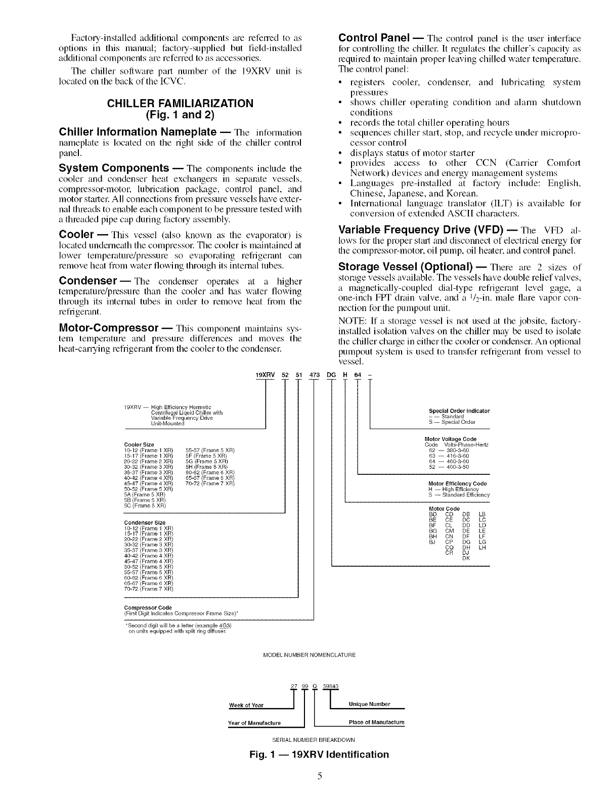
FactolT-installed additional components tue refen_ed to as
options in this manual; factou-supplied but field-installed
additional components are referred to as accessories.
The chiller software pall number of the 19XRV unit is
located on the back of the ICVC.
CHILLER FAMILIARIZATION
(Fig. 1 and 2)
Chiller Information Nameplate -- The information
nameplate is located on the right side of the chiller control
panel.
System Components -- The components include the
cooler and condenser heat exchangers in separate vessels,
compressor-motor, lubrication package, control panel, and
motor sttutel: All connections fiom pressure vessels have exter-
nal threads to enable each component to be plessure tested with
a thleaded pipe cap during factory assembly.
Cooler- This vessel (also known as the evaporator) is
located underneath the compressol: The cooler is maintained at
lower temperature/pressme so evaporating refrigerant can
remove heat fiom water flowing through its internal tubes.
Condenser--The condenser operates at a higher
temperature/pressure than the cooler and has water flowing
through its internal tubes in order to remove heat fi_)m the
refrigerant.
Motor-Compressor- This component mainttfins sys-
tem temperature and pressure differences and moves the
heat-carrying refrigerant from the cooler to the condenser
19XRV -- High Efficiency Hermetic
Centrifugal Liquid Chiller with
Variable Frequency Drive
Unit-Mounted
19XRV 52 51 473
/
Cooler Size
10-12 (Frame 1 XR) 55-57 (Frame 5 XR)
15-17 (Frame 1 XR) 5F (Frame 5 XR)
20-22 (Frame 2 XR) 5G (Frame 5 XR)
30-32 (Frame 3 XR) 5H (Frame 5 XR)
35-37 (Frame 3 XR) 60-62 (Frame 6 XR)
40-42 (Frame 4 XR) 65-67 (Frame 6 XR)
45-47 (Frame 4 XR) 70-72 (Frame 7 XR)
50-52 (Frame 5 XR)
5A (Frame 5 XR)
5B (Frame 5 XR)
50 (Frame 5 XR)
Condenser Size
10-12 (F .... 1 XR /
15-17 (Frame 1
20-22 (Frame 2 XR)
30-32 (Frame 3 XR)
35-37 (Frame 3 XR)
40-42 (Frame 4 XR)
45-47 (Frame 4 XR)
50-52 (Frame 5 XR)
55-57 (Frame 5 XR)
60-62 (Frame 6 XR)
65-67 (Frame 6 XR)
70-72 (Frame 7 XR)
Compressor Code
(First Digit Indicates Compressor Frame Size) _
*Second digit will be a letter (example 4G3)
on units equipped with split ring diffuser.
DG
Control Panel -- The control panel is the user interface
for controlling the chiller It regulates the chiller's capacity as
lequiled to maintain proper leaving chilled water temperature.
The control panel:
• registers cooler, condenser, and lubricating system
pressures
• shows chiller operating condition and alarm shutdown
conditions
• records the total chiller operating hours
• sequences chiller start, stop, and recycle under micropro-
cessor control
• displays status of motor starter
• provides access to other CCN (Carrier Comfort
Network) devices and energy management systems
• Languages pre-installed at factory include: English,
Chinese, Japanese, and Korean.
• International language translator (ILT) is available for
conversion of extended ASCII characters.
Variable Frequency Drive (VFD) -- The VFD al-
lows for the proper st_ut and disconnect of electrical energy for
the compressor-motor, oil pump, oil heater, and control panel.
Storage Vessel (Optional)--There are 2 sizes of
storage vessels available. The vessels have double relief valves,
a magnetically-coupled dial-type refrigerant level gage, a
one-inch FPT drain valve, and a l/2-in, male flare vapor con-
nection for the pumpout unit.
NOTE: If a storage vessel is not used at the jobsite, factory-
installed isolation valves on the chiller may be used to isolate
the chiller charge in either the cooler or condenser. An optional
pumpout system is used to transfer refrigerant from vessel to
vessel.
64 -
Special Order Indicator
- -- Standard
S -- Special Order
Motor Voltage Code
Code Volts-Phase-Hertz
62 -- 380-3-60
63 -- 416-3-60
64 -- 460-3-60
52 -- 400-3-50
Motor Efficiency Code
H -- High Efficiency
S -- Standard Efficiency
Motor Code
BD CD DB LB
BE CE DC LC
BF CL DD LD
BG CM DE LE
BH ON DF LF
BJ CP DG LG
CQ DH LH
OR DJ
DK
MODELNUMBERNOMENCLATURE
27 99 Q 59843
Year of Manufacture Place of Manufacture
SERIAL NUMBER BREAKDOWN
Fig. 1 -- 19XRV Identification
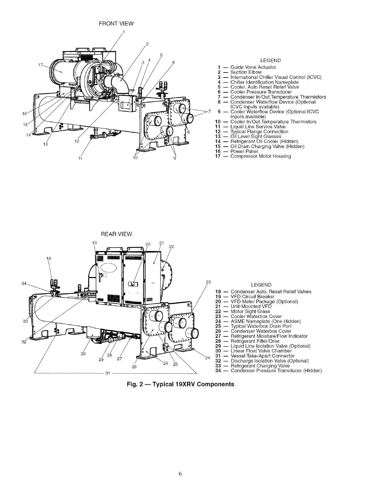
FRONT VIEW
144
13
10
5
6LEGEND
1 -- Guide Vane Actuator
2 -- Suction Elbow
3 -- International Chiller Visual Control (ICVC)
4 -- Chiller Identification Nameplate
5 -- Cooler, Auto Reset Relief Valve
6 -- Cooler Pressure Transducer
7 -- Condenser In/Out Temperature Thermistors
8 -- Condenser Waterflow Device (Optional
ICVC Inputs available)
9 -- Cooler Waterflow Device (Optional ICVC
Inputs available)
10 -- Cooler In/Out Temperature Thermistors
11 -- Liquid Line Service Valve
12 -- Typical Flange Connection
13 -- Oil Level Sight Glasses
14 -- Refrigerant Oil Cooler (Hidden)
15 -- Oil Drain Charging Valve (Hidden)
16 -- Power Panel
17 -- Compressor Motor Housing
18
REAR VIEW
19 2O 21 22
32
29 27
26
31
23
18
19
20
21
22
23
24
25
26
27
28
29
3O
24 31
32
33
34
LEGEND
-- Condenser Auto. Reset Relief Valves
-- VFD Circuit Breaker
-- VFD Meter Package (Optional)
-- Unit-Mounted VFD
-- Motor Sight Glass
-- Cooler Waterbox Cover
-- ASME Nameplate (One Hidden)
-- Typical Waterbox Drain Port
-- Condenser Waterbox Cover
-- Refrigerant Moisture/Flow Indicator
-- Refrigerant Filter/Drier
-- Liquid Line Isolation Valve (Optional)
-- Linear Float Valve Chamber
-- Vessel Take-Apart Connector
-- Discharge Isolation Valve (Optional)
-- Refrigerant Charging Valve
-- Condenser Pressure Transducer (Hidden)
Fig. 2 --Typical 19XRV Components
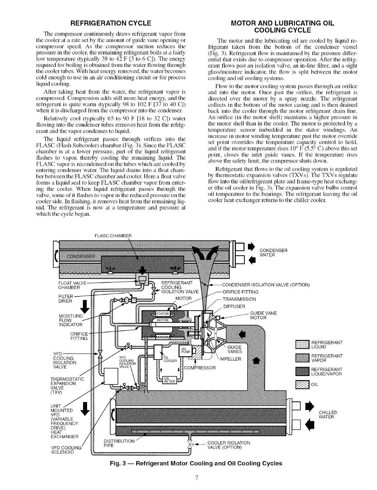
REFRIGERATION CYCLE
The compressor continuously draws refrigerant vapor from
the cooler at a rate set by the amount of guide vane opening or
compressor speed. As the compressor suction reduces the
pressure in the coolel: the remaining refrigerant boils at a fairly
low temperature (typically 38 to 42 F [3 to 6 C]). Tile energy
required for boiling is obtained from the water flowing through
the cooler tubes. With heat energy removed, the water becomes
cold enough to use in tin air conditioning circuit or for process
liquid cooling.
After taking heat from the water, the refrigerant vapor is
compressed. Compression adds still more heat energy, and the
refrigerant is quite wmm (typic_flly 98 to 102 F [37 to 40 C])
when it is discharged t]om the compressor into the condensel:
Relatively cool (typically 65 to 90 F [18 to 32 C]) water
flowing into the condenser tubes removes heat from the refrig-
erant and the vapor condenses to liquid.
The liquid refi'igerant passes through orifices into the
FLASC (Flash Subcooler) chamber (Fig. 3). Since the FLASC
chamber is at a lower plessure, part of the liquid refrigerant
flashes to vapol: thereby cooling the lemaining liquid. The
FLASC vapor is recondensed on the tubes which are cooled by
entering condenser watel: The liquid drains into a float cham-
ber between the FLASC chamber and cooler Here a float v_dve
forms a liquid seal to keep FLASC chamber vapor from enter-
ing the coolel: When liquid refrigerant passes through the
vMve, some of it flashes to vapor in the reduced pressure on the
cooler side. In flashing, it removes heat from the remaining liq-
uid. The refrigerant is now at a temperature and plessure at
which the cycle began.
MOTOR AND LUBRICATING OIL
COOLING CYCLE
The motor and the lubricating oil are cooled by liquid re-
frigerant taken from the bottom of the condenser vessel
(Fig. 3). Refrigerant flow is maintained by the pressure differ-
ential that exists due to compressor operation. After the refrig-
erant flows past an isolation valve, tin in-line filtel: and a sight
glass/moisture indicatol: the flow is split between the motor
cooling and oil cooling systems.
Flow to the motor cooling system passes through an orifice
and into the motor. Once past the orifice, the refrigerant is
directed over the motor by a spray nozzle. The refrigerant
collects in the bottom of the motor casing and is then drained
back into the cooler through the motor refrigerant di'ain line.
An orifice (in the motor shell) maintains a higher pressure in
the motor shell than in the coolel: The motor is protected by a
temperature sensor imbedded in the stator windings. An
increase in motor winding temperature past the motor override
set point overrides the temperatme capacity control to hold,
and if the motor temperature rises 10° F (5.5 ° C) above this set
point, closes the inlet guide vanes. If the temperature rises
above the safety limit, the compressor shuts down.
Refrigerant that flows to the oil cooling system is regulated
by thermostatic expansion valves (TXVs). The TXVs regulate
flow into the oil/lefrigerant plate and fralne-type heat exchang-
er (the oil cooler in Fig. 3). The expansion valve bulbs control
oil temperature to the bemings. The refrigerant leaving the oil
cooler heat exchanger returns to the chiller coolel:
FLASC CHAMBER
CONDENSER
WATER
Ii
FLOATVAWE.
CHAMBER
DRIER
MOISTURE/
FLOW
INDICATOR
ORIFICE-
FITTING
VFD'
COOLING
ISOLATION
VALVE
THERMOSTATIC
EXPANSION
VALVE
(TXV)
UNIT
MOUNTED
VFD
(VARIABLE
FREQUENCY
DRIVE)
HEAT
EXCHANGER
SOLENOID
VALVE (OPTION)
DIFFUSER
VANE
MOTOR
COOLER ISOLATION
VALVE (OPTION)
Fig. 3 -- Refrigerant Motor Cooling and Oil Cooling Cycles
REFRIGERANT
LIQUID
REFRIGERANT
VAPOR
_ EFRIGERANT
LIQUID/VAPOR
F_ OIL
CHILLED
WATER
VFD COOLING CYCLE
The unit-mounted variable frequency drive (VFD) is cooled
in a manner similar to the motor and lubricating oil cooling
cycle (Fig. 3).
If equipped with a unit-mounted VFD, the refrigerant line
that feeds the motor cooling and oil cooler also feeds the heat
exchanger on the unit-mounted VFD. Refrigerant is metered
through a thermostatic expansion valve (TXV). To maintain
proper operating temperature in the VFD, the TXV bulb is
mounted to the heat exchanger to regulate the flow of refdger-
ant. The refdgerant leaving the heat exchanger returns to the
coolel:
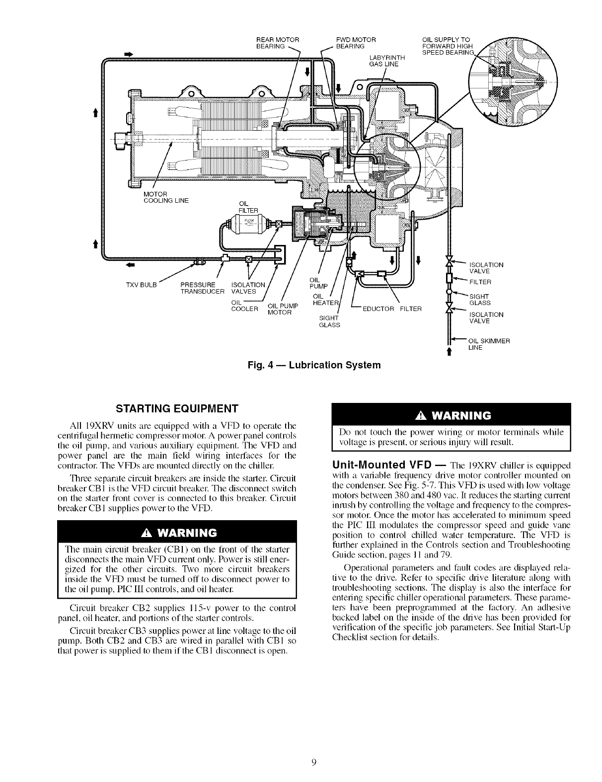
LUBRICATION CYCLE
Summary -- The oil pump, oil filtel; and oil cooler make
up a package located p_utially in the transmission casing of the
compressor-motor assembly. The oil is pumped into a filter
assembly to remove foreign particles and is then forced into an
oil cooler heat exchanger where the oil is cooled to proper
operational temperatures. After the oil cooler, part of the flow
is directed to the gems and the high speed shaft bearings; the
remaining flow is directed to the motor shaft bearings. Oil
drains into the transmission oil sump to complete the cycle
(Fig. 4).
Details -- Oil is charged into the lubrication system through
a hand valve. Two sight glasses in the oil reservoir permit oil
level observation. Normal oil level is between the middle of the
upper sight glass and the top of the lower sight glass when the
compressor is shut down. The oil level should be visible in at
least one of the 2 sight glasses during operation. Oil sump
temperature is displayed on the ICVC (International Chiller
Visual Controller) default screen. During compressor opera-
tion, the oil sump temperature ranges between 125 and 150 F
(52 and 66 C).
The oil pump suction is fed from the oil reservoil: An oil
pressure relief valve maintains 18 to 30 psid (124 to 207 kPad)
differential pressure in the system at the pump discharge. The
normal oil pressme on compressors equipped with rolling
element bearings is between 18 and 40 psid (124 and
276 kPad). This diffelential pressure can be read directly from
the [CVC default scleen. The oil pump discharges oil to the oil
filter assembly. This filter can be closed to permit removal of
the filter without dnfining the entire oil system (see Mainte-
nance sections, pages 75 to 78, for details). The oil is then
piped to the oil cooler heat exchangel: The oil cooler uses
refrigerant from the condenser as the coolant. The refrigerant
cools the oil to a temperature between 120 and 140 F (49 and
60 C).
As the oil leaves the oil cooler, it passes the oil pressure
transducer and the thermal bulb for the refrigerant expansion
vNve on the oil cooler The oil is then divided. Pro1 of the oil
flows to the thrust bearing, %rward pinion bearing, and gear
spray. The rest of the oil lubricates the motor shaft bearings and
the rear pinion beming. The oil temperature is measured in the
bearing housing as it leaves the thrust and forwaN journal
bearings. The outer bearing race temperature is measured on
compressors with rolling element bemings. The oil then drains
into the oil reservoir at the base of the compmssol: The PIC III
(Product Integrated Control III) measures the temperature of
the oil in the sump and maintNns the temperature during shut-
down (see Oil Sump Temperature and Pump Control section,
page 39). This temperature is mad on the ICVC default screen.
Dudng chiller stmt-up, the PIC Ill energizes the oil pump
and provides 45 seconds of pro-lubrication to the be_uings after
pressure is verified before starting the compressor During
shutdown, the oil pump will mn for 60 seconds to post-
lubricate after the compressor shuts down. The oil pump can
also be energized for testing purposes during a Control Test.
Ramp loading can slow the rate of guide vane opening to
minimize oil foaming at st_ut-up. If the guide vanes open
quickly, the sudden drop in suction pressure can cause any
refrigerant in the oil to flash. The resulting oil foaln cannot be
pumped efficiently; therefore, oil pressure falls off and lubrica-
tion is pool: If oil pressure falls below 15 psid (103 kPad)
differential, the PIC III will shut down the compressol:
If the controls me subject to a power failure that lasts more
than 3 hours, the oil pump will be energized periodically when
the power is restored. This helps to eliminate lefrigerant that
has migrated to the oil sump during the power failure. The
controls energize the pump for 30 seconds every 30 minutes
until the chiller is started.
Oil Reclaim System -- The oil reclaim system returns
oil lost from the compressor housing back to the oil reservoir
by recovering the oil from 2 meas on the chillel: The guide
vane housing is the primary area of recovery. Oil is also recov-
ered by skimming it from the operating refrigerant level in the
cooler vessel.
PRIMARY OIL RECOVERY MODE -- Oil is normally re-
covered through the guide vane housing on the chillel: This is
possible because oil is normally entrained with refrigerant in
the chillel: As the compressor pulls the refrigerant up from the
cooler into the guide vane housing to be compressed, the oil
norm_dly drops out at this point and falls to the bottom of the
guide vane housing where it accumulates. Using discharge gas
pressure to power an eductol: the oil is diawn from the housing
and is dischmged into the oil reservoil:
SECONDARY OIL RECOVERY METHOD -- The sec-
on&try method of oil recovery is significant under light load
conditions, when the refrigerant going up to the compressor
suction does not have enough velocity to bring oil along. Under
these conditions, oil collects in a greater concentration at the
top level of the refrigerant in the coolel: This oil and refrigerant
mixture is skimmed from the side of the cooler and is then
drawn up to the guide vane housing. There is a filter in this line.
Because the guide vane housing pressure is much lower than
the cooler pressure, the refrigerant boils off. leaving the oil
behind to be collected by the primary oil recovery method.
Bearings -- The 19XRV compressor assemblies include
four radi_d bemings and four thrust bearings. The low speed
shaft assembly is suppolled by two journal bemings located
between the motor rotor and the bull gem: The bearing closer to
the rotor includes a babbitted thrust face which opposes the
normal axial forces which tend to pull the assembly towmds
the transmission. The beming closer to the bull gear includes a
smaller babbitted thrust face, designed to handle counterthmst
forces.
For most 19XRV compressors the high speed shaft assem-
bly is supported by two journal bearings located at the
transmission end and mid-span, behind the labyrinth seal. The
transmission side of the midspan bearing _dso contains a tilting
shoe type thrust beming which opposes the main axkd forces
tending to pull the impeller towards the suction end. The
impeller side face of the midspan bearing includes a babbitted
thrust face, designed to handle counterthrust forces.
For 19XRV Frmne 3 compressors built since mid-2001, the
high speed shaft assembly has been redesigned to utilize rolling
element bearings (radial and thrust). Machines employing the
rolling element bearings can be expected to have higher oil
pressure and thrust beming temperatures than those compres-
sors using the alternate bearing design.
REAR MOTOR OIL SUPPLY TO
FORWARD HIGH
SPEED BEARING
I
(
FWD MOTOR
LABYRINTH
GAS LINE
MOTOR
COOLING LINE
PRESSURE
TRANSDUCER
OIL
ISOLATION PUMP
VALVES OIL
OIL HEATER
COOLER OILPUMP
MOTOR SIGHT
GLASS
FILTER
ISOLATION
VALVE
GLASS
ISOLATION
VALVE
Fig. 4- Lubrication System
t LINE
STARTING EQUIPMENT
All 19XRV units am equipped with a VFD to operate the
centrifugal hermetic compressor motoc A power panel controls
the oil pump, and various auxiliary equipment. The VFD and
power panel m'e the main field wiring interfaces for the
contractol: The VFDs are mounted directly on the chillel:
Three separate circuit breakers ale inside the st_utel: Circuit
breaker CBI is the VFD circuit breaker The disconnect switch
on the stmler fiont cover is connected to fills breakel: Circuit
breaker CBI supplies power to the VH).
The main circuit breaker (CBI) on the front of the starter
disconnects the main VFD current only. Power is still ener-
gized for the other circuits. Two more circuit breakers
inside the VH) must be turned off to disconnect power to
the oil pump, PIC III controls, and oil heatel:
Circuit breaker CB2 supplies l15-v power to the control
panel, oil heater, and portions of the starter controls.
Circuit breaker CB3 supplies power at line voltage to the oil
pump. Both CB2 and CB3 are wired in pm'allel with CBI so
that power is supplied to them if the CBI disconnect is open.
Do not touch the power wiring or motor terminals while
voltage is present, or serious injury will result.
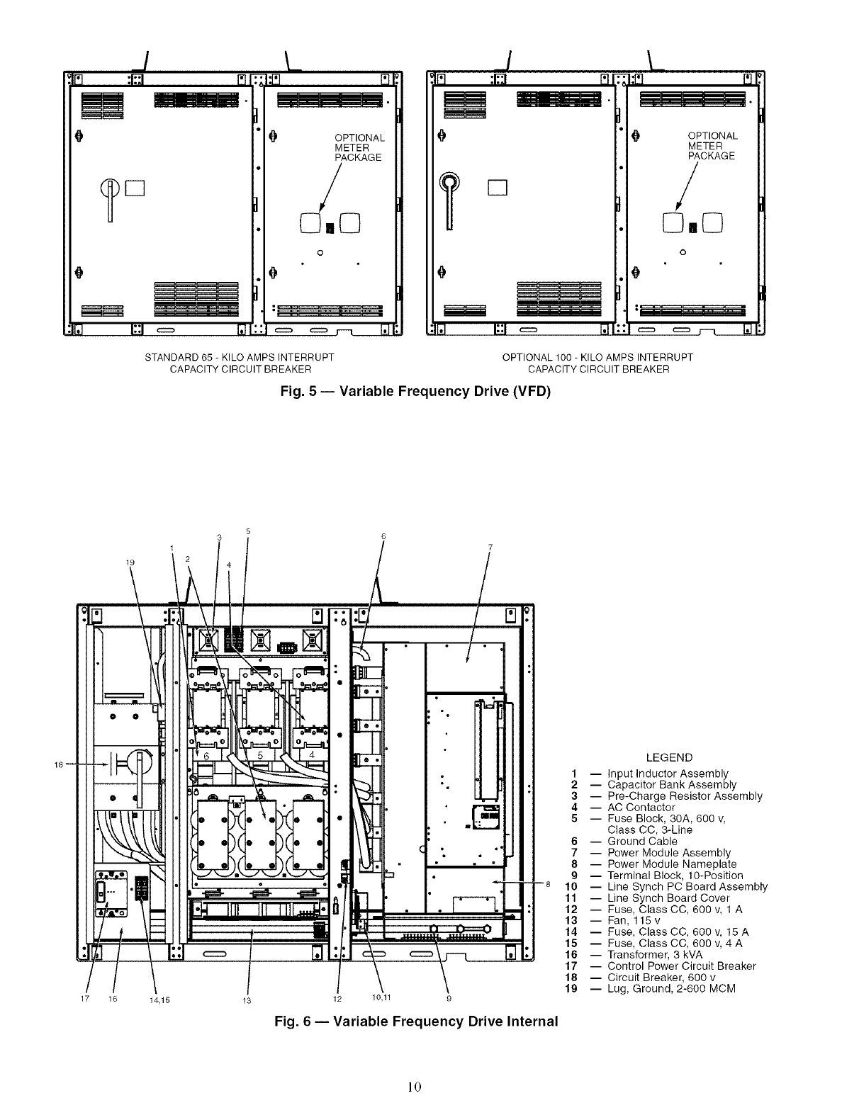
Unit-Mounted VFD -- The 19XRV chiller is equipped
with a variable frequency drive motor controller mounted on
file condensel: See Fig. 5-7. This VFD is used wifll low voltage
motors between 380 and 480 wtc. It reduces the starting current
inrush by controlling the voltage and fiequency to the compres-
sor motol: Once the motor has accelerated to minimum speed
the PIC IIl modulates the compressor speed and guide vane
position to control chilled water temperature. The VFD is
further explained in the Controls section and Troubleshooting
Guide section, pages 11 and 79.
Operational p_uameters and fault codes are displayed rela-
tive to the drive. Refer to specific (hive literatme along with
troubleshooting sections. The display is _dso the interface for
entering specific chiller operational p_u'ametel_. These ptuame-
ters have been preprogrammed at the factory. An adhesive
backed label on the inside of the drive has been provided for
verification of the specific job paralneters. See Initial St_ut-Up
Checklist section for details.
17
OPTIONAL
METER
PACKAGE
o./o
o
[]
I II II n11 I .
{t OPTIONAL
METER
PACKAGE
/
0o0
o
STANDARD 65 - KILO AMPS INTERRUPT
CAPACITY CIRCUIT BREAKER
OPTIONAL 100 - KILO AMPS INTERRUPT
CAPACITY CIRCUIT BREAKER
Fig. 5 -- Variable Frequency Drive (VFD)
5
3
14,15 13 12 10,11 9
Fig. 6 -- Variable Frequency Drive Internal
1 m
2 --
3--
4 --
5 --
6 --
7--
8 --
9--
10 --
11 --
12 --
13 --
14 --
15 --
16 --
17 --
18 --
19 --
LEGEND
Input Inductor Assembly
Capacitor Bank Assembly
Pre-Charge Resistor Assembly
AC Contactor
Fuse Block, 30A, 600 v,
Class CC, 3-Line
Ground Cable
Power Module Assembly
Power Module Nameplate
Terminal Block, 10-Position
Line Synch PC Board Assembly
Line Synch Board Cover
Fuse, Class CC, 600 v, 1 A
Fan, 115 v
Fuse, Class CC, 600 v, 15 A
Fuse, Class CC, 600 v, 4 A
Transformer, 3 kVA
Control Power Circuit Breaker
Circuit Breaker, 600 v
Lug, Ground, 2-600 MCM
10
GUIDE VANE POWER PANEL CABLE
COOLER CHARGING CONTROL PANEL ACTUATOR CABLE
VALVE (HIDDEN)
WATER SEN_
CABLES
j cO2?s s'S 2
COOLER PRESSURE CABLE
TRANSDUCER
CONNECTION
/
SCHRADER
FITTING(HIDDEN)
CONDENSER
PRESSURE
TRANSDUCER
CONNECTION
CONDENSER CONDENSER
3-WAY SHUTOFF CHARGING
VALVE VALVE (HIDDEN)
COMPRESSOR
DISCHARGE
ELBOW JOINTS
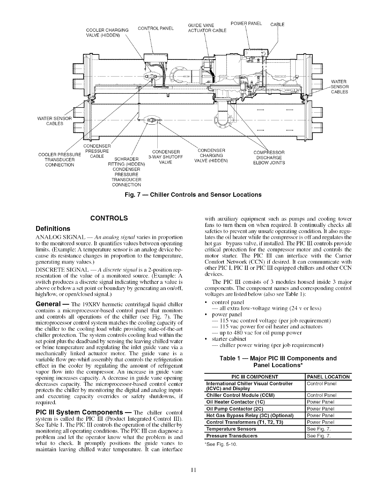
Fig. 7 -- Chiller Controls and Sensor Locations
WATER
CABLES
CONTROLS
Definitions
ANALOG SIGNAL -- An analog signal varies in proportion
to the monitored source. It quantifies values between operating
limits. (Example: A temperature sensor is an analog device be-
cause its resistance changes in proportion to the temperature,
generating many values.)
DISCRETE SIGNAL --A discreW signal is a 2-position rep-
resentation of the value of a monitored source. (Example: A
switch produces a discrete signal indicating whether a value is
above or below a set point or boun&uy by generating an on/off.
high/low, or open/closed signed.)
General -- The 19XRV herlnetic centrifuged liquid chiller
contains a microprocessor-based control panel that monitors
and controls all operations of the chiller (see Fig. 7). The
microprocessor control system matches the cooling capacity of
the chiller to the cooling load while providing state-of-the-art
chiller protection. The system controls cooling load within the
set point plus the deadband by sensing the leaving chilled water
or brine temperature and regulating the inlet guide vane via a
mechanically linked actuator motol: The guide vane is a
variable flow pre-whifl assembly that controls the refrigeration
effect in the cooler by regulating the amount of refrigerant
vapor flow into the compressor. An increase in guide vane
opening increases capacity. A decrease in guide vane opening
decreases capacity. The microprocessor-based control center
protects the chiller by monitoring the digital and analog inputs
and executing capacity overrides or safety shutdowns, if
required.
PIC III System Components -- The chiller control
system is called the PIC 1II (Product Integrated Control [II).
See Table 1. The PIC III controls the operation of the chiller by
monitoring all operating conditions. The PIC III can diagnose a
problem and let the operator know what the problem is and
what to check. It promptly positions the guide vanes to
m_fint_fin leaving chilled water temperature. It can interface
with auxiliary equipment such as pumps and cooling tower
fans to turn them on when required. It continually checks all
safeties to prevent any unsafe operating condition. It also regu-
lates the oil heater while the compressor is off and regulates the
hot gas bypass valve, if installed. The PIC III controls provide
critical protection for the compressor motor and controls the
motor stmlel: The PIC III can interface with the Carrier
Comfort Network (CCN) if desired. It can communicate with
other PIC I, PIC II or PIC III equipped chillers and other CCN
devices.
The PIC [II consists of 3 modules housed inside 3 major
components. The component names and corresponding control
voltages are listed below (also see Table 1):
•control panel
-- all extra low-voltage wiring (24 v or less)
• power panel
-- 115 vac control voltage (per job requirement)
-- 115 vac power for oil heater and actuators
-- up to 480 vac for oil pump power
• starter cabinet
-- chiller power wiring (per job requirement)
Table 1 -- Major PIC III Components and
Panel Locations*
PIC III COMPONENT
International Chiller Visual Controller
(ICVC) and Display
Chiller Control Module (CCM)
Oil Heater Contactor (1C)
Oil Pump Contactor (2C)
Hot Gas Bypass Relay (3C) (Optional)
Control Transformers (T1, T2, T3)
Temperature Sensors
Pressure Transducers
*See Fig, 5-10.
PANEL LOCATION
Control Panel
Control Panel
Power Panel
Power Panel
Power Panel
Power Panel
See Fig, 7.
See Fig, 7.
11
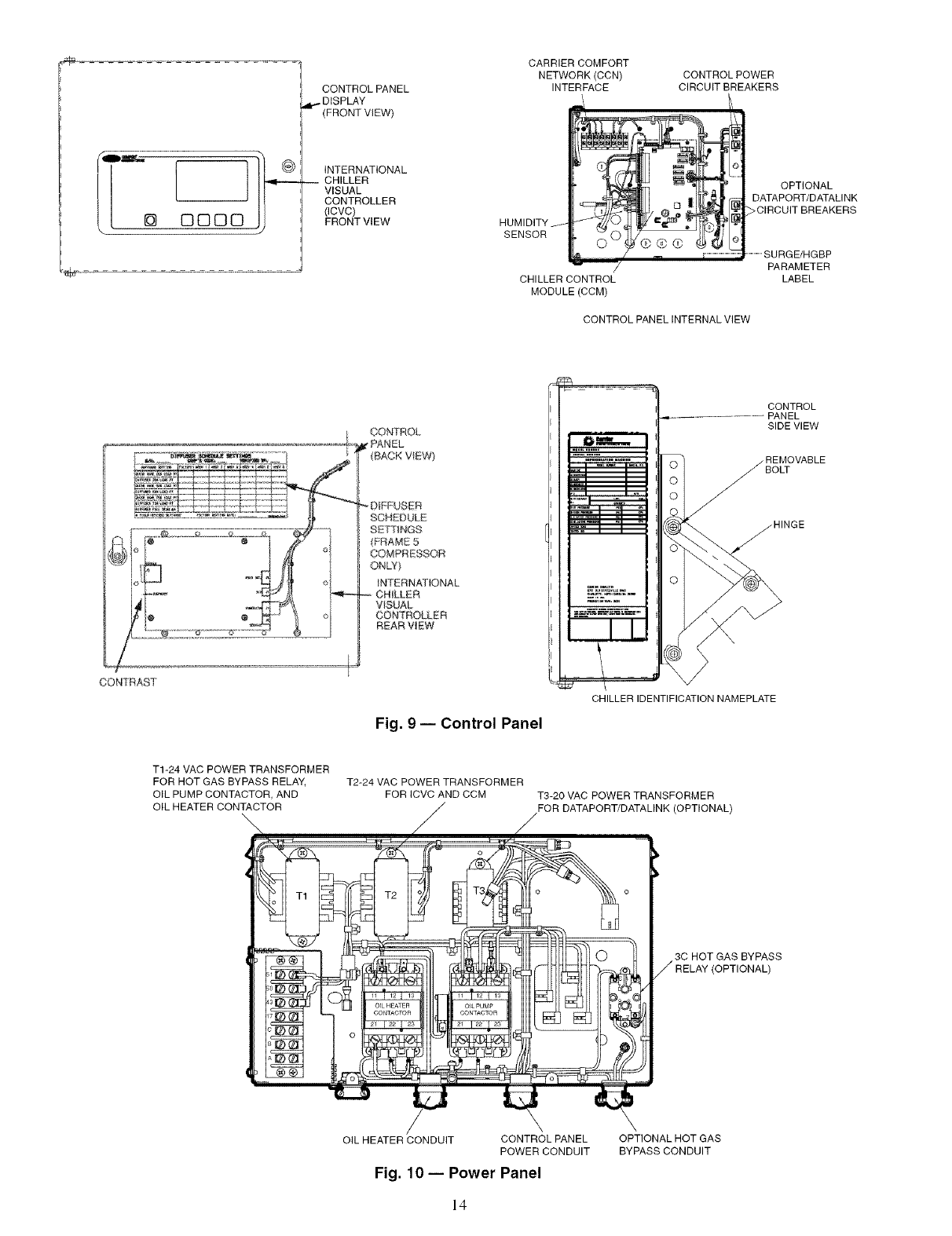
INTERNATIONAL CHILLER VISUAL CONTROLLER
(ICVC) -- The ICVC is the "brain" of the PIC HI. This mod-
ule contains all the operating software needed to control the
chillel: The ICVC is mounted to the control panel (Fig. 9) and
is the input center for all local chiller set points, schedules,
configurable functions, and options. The [CVC has a stop
button, an alarm light, four bnttons for logic inputs, and a
backlight display. The backlight will automatically turn off
after 15 minutes of non-use. The lhnctions of the four buttons
or "softkeys" me menu driven and are shown on the display
directly above the softkeys.
The viewing angle of the ICVC can be adjusted for opti-
mum viewing. Remove the 2 bolts connecting the control panel
to the brackets attached to the coolec Place them in one of the
holes to pivot the control panel forw_ud to backward to change
the viewing angle. See Fig. 9. To change the contrast of the
display, access the adjustment on the back of the ICVC. See
Fig. 9.
The ICVC features 4 factory progrmnmed languages:
English (default)
Chinese
Japanese
Kolean
NOTE: Plessing any one of the four softkey buttons will acti-
vate the backlight display without implementing a softkey
function.
The [CVC may be identified by viewing the back of the plate
on which the display is mounted. (Open the control panel door
to view.) Note any of the following distinguishing features in
Table 2.
Table 2 -- Identification Features of the ICVC
COLOR CEPL No.
CONTROLLER OF (hardware)
PLATE
ICVC Metallic CEPL
130445-02
SOFTWARE
CESR
131350-0X
OTHER
MARKINGS
"PIC IIr'
Marking
on back
of green
circuit
board
MOTOR TEMPERATURE
OIL RECLAIM
SIGHT GLASS_
COMPRESSOR OIL DISCHARGE
PRESSURE CABLE
BEARING TEMPERATURE
CABLE
AND DIFFUSER ACTUATOR
CABLE (FRAME 4 & 5
COMPRESSOR ONLY)
COMPRESSOR OIL SUMP
COMPRESSOR OIL SUMP
GUIDE
ACTUATOR CABLE
CABLE FROM
CONTROL PANEL
COMPRESSOR DISCHARGE
TEMPERATURE SENSOR
CABLE
HIGH PRESSURE
SWITCH LOCATION
OIL COOLER THERMOSTATIC
EXPANSION VALVE (TXV)
OIL COOLER THERMOSTATIC
EXPANSION VALVE (TXV) BULB
OIL HEATER TERMINAL
BOX
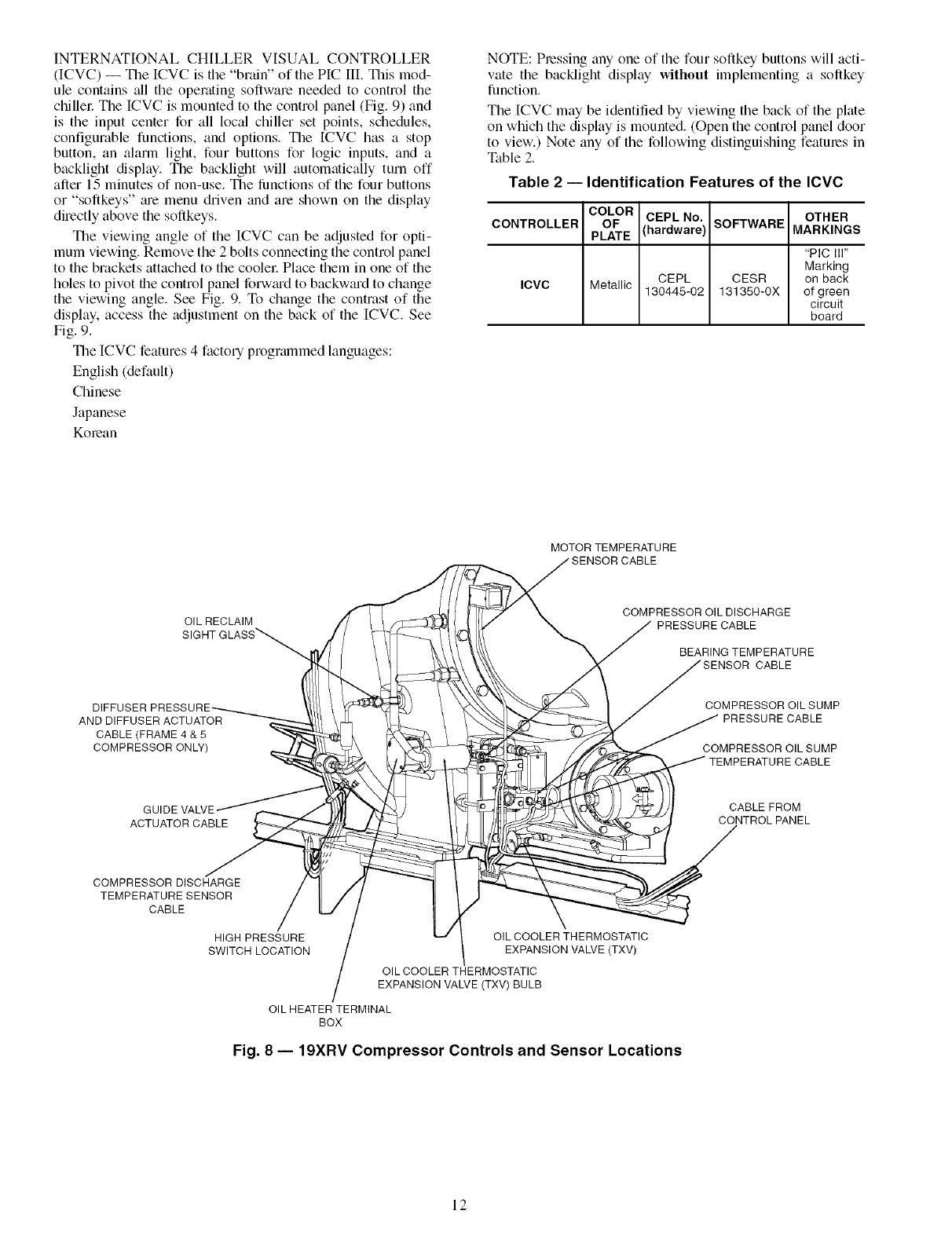
Fig. 8 -- 19XRV Compressor Controls and Sensor Locations
12
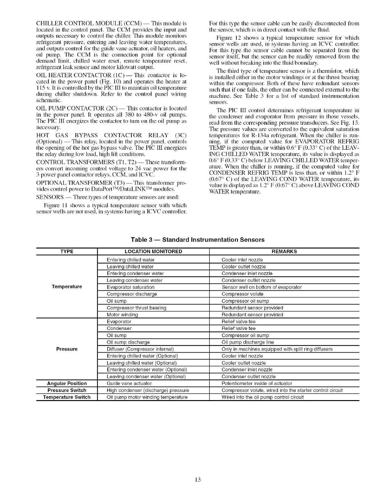
CHILLER CONTROL MODULE (CCM) -- This module is
located in file control panel. Tile CCM provides the input and
outputs necessa Uto control the chillel: This module monitors
refiigerant pressure, entering and leaving water temperatures,
and outputs control for the guide vane actuator, oil heaters, and
oil pump. The CCM is the connection point for optional
demand limit, chilled water reset, remote temperature reset,
refi'igerant leak sensor and motor kilowatt output.
OIL HEATER CONTACTOR (IC) -- This contactor is lo-
cated in the power panel (Fig. 10) and operates the heater tit
115 v. It is controlled by the PIC III to maintain oil temperature
during chiller shutdown. Refer to the control panel wiring
schematic.
OIL PUMP CONTACTOR (2C) -- This contactor is located
in the power panel. It operates all 380 to 480-v oil pumps.
The PIC HI energizes the contactor to turn on the oil pump as
necessm-y.
HOT GAS BYPASS CONTACTOR RELAY (3C)
(Optional) -- This relay, located in the power panel, controls
the opening of the hot gas bypass valve. The PIC III energizes
the relay during low load, high lill conditions.
CONTROL TRANSFORMERS (TI, T2)- These transform-
ers convert incoming control voltage to 24 vac power for the
3 power panel contactor relays, CCM, and ICVC.
OPTIONAL TRANSFORMER (T3)--This transformer pro-
vides control power to DataPort'rWDataLINK TM modules.
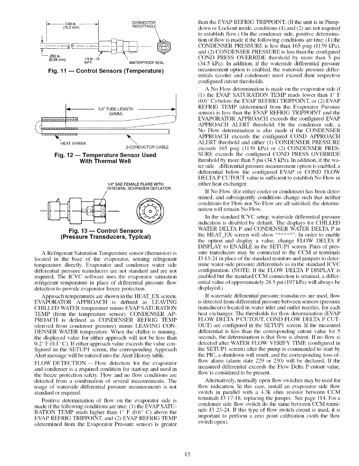
SENSORS -- Throe types of temperature sensors am used:
Figure 11 shows a typictd temperature sensor with which
sensor wells am not used, in systems having a ICVC controllel:
For this type the sensor cable can be easily disconnected fiom
the sensok which is in direct contact with the fluid.
Figure 12 shows a typictd temperature sensor for which
sensor wells am used, in systems having an ICVC controllel:
For this type the sensor cable cannot be separated from the
sensor itself, but the sensor can be readily removed from the
well without breaking into the fluid boun&u-y.
The third type of temperature sensor is a thermistok which
is installed either in the motor windings or tit the thrust bearing
within the compressol: Both of these have redun&mt sensors
such flintif one fails, the other can be connected external to the
machine. See NiNe 3 for a list of stan&trd instrumentation
sensors.
The PIC [II control determines refrigerant temperature in
the condenser and evaporator fi_m pressure in those vessels,
mad fi_m the conesponding pressure transducers. See Fig. 13.
The pressure values are converted to the equivtdent saturation
temperatures for R-134a refrigerant. When the chiller is run-
ning, if the computed value for EVAPORATOR REFRIG
TEMP is greater than, or within 0.6° F (0.33° C) of the LEAV-
ING CHILLED WATER temperature, its value is displayed as
0.6° F (0.33° C) below LEAVING CHILLED WATER tempe>
atum. When the chiller is running, if the computed value for
CONDENSER REFRIG TEMP is less than, or within 1.2° F
(0.67° C) of the LEAVING COND WATER temperature, its
value is displayed as 1.2° F (0.67 ° C) above LEAVING COND
WATER temperature.
Table 3 -- Standard Instrumentation Sensors
TYPE LOCATION MONITORED REMARKS
Entering chilled water Cooler inlet nozzle
Leaving chilled water Cooler outlet nozzle
Entering condenser water Condenser inlet nozzle
Leaving condenser water Condenser outlet nozzle
Temperature Evaporator saturation Sensor well on bottom of evaporator
Compressor discharge Compressor volute
Oil sump Compressor oil sump
Compressor thrust bearing Redundant sensor provided
Motor winding Redundant sensor provided
Evaporator Relief valve tee
Condenser Relief valve tee
Oil sump Compressor oil sump
Oil sump discharge Oil pump discharge line
Pressure Diffuser (Compressor internal) Only in machines equipped with split ring diffusers
Entering chilled water (Optional) Cooler inlet nozzle
Leaving chilled water (Optional) Cooler outlet nozzle
Entering condenser water (Optional) Condenser inlet nozzle
Leaving condenser water (Optional) Condenser outlet nozzle
Angular Position Guide vane actuator Potentiometer inside of actuator
Pressure Switch High condenser (discharge) pressure Compressor volute, wired into the starter control circuit
Temperature Switch Oil pump motor winding temperature Wired into the oil pump control circuit
13
_÷
fo_m_,
0000
CONTROL PANEL
DISPLAY
(FRONT VIEW)
INTERNATIONAL
CHILLER
VISUAL
CONTROLLER
(ICVC)
FRONT VIEW
CARRIER COMFORT
NETWORK (CCN)
INTERFACE
HUMIDITY
SENSOR
CHILLER CONTROL
MODULE (CCM)
CONTROL POWER
CIRCUIT BREAKERS
r
@GG ( (
OPTIONAL
DATAPORT/DATAU NK
>CIRCUIT BREAKERS
.............SURGE/HGBP
PARAMETER
LABEL
CONTROL PANEL INTERNAL VIEW
CONTROl.
DIFFUSER
SCHEDULE
SETTINGS
(FRAME 5
COMPRESSOR
ONLY)
INTERNATIONAL
VISUAL
OONTRO_ER
REAR VIEW
CONTROL
PANEL
SIDE VIEW
REMOVABLE
BOLT
HINGE
CONTRAST
Fig. 9- Control Panel
CHILLER IDENTIFICATION NAMEPLATE
T1-24 VAC POWER TRANSFORMER
FOR HOT GAS BYPASS RELAY,
OIL PUMP CONTACTOR, AND
OIL HEATER CONTACTOR
T2-24 VAC POWER TRANSFORMER
FOR ICVC AND CCM T3-20 VAC POWER TRANSFORMER
FOR DATAPORT/DATALINK (OPTIONAL)
3C HOT GAS BYPASS
OIL HEATER CONDUIT CONTROL PANEL
POWER CONDUIT
Fig. 10 -- Power Panel
OPTIONAL HOT GAS
BYPASS CONDUIT
14
L,_ 3 00in ............ _-J CONNECTOR
_-_-_ _----_i6,35"mm)(762 mm) ,.- RECEPTACLE
NPT WATERPROOF SEAL
Fig. 11 -- Control Sensors (Temperature)
3.6" TUBE LENGTH
(90MM)
\EATSHR,NK\
2-CONDUCTOR CABLE
Fig. 12 -- Temperature Sensor Used
With Thermal Well
1/4" SAE FEMALE FLARE WITH
INTEGRAL SCHRADER DEFLATOR
Fig. 13 -- Control Sensors
(Pressure Transducers, Typical)
A Refrigerant Saturation Temperature sensor (thermistor) is
located in the base of the evaporator, sensing refrigerant
temperature directly. Evaporator and condenser water side
differential pressure transducers _u'e not stan&trd and are not
required. The [CVC software uses the evaporator saturation
refrigerant temperature in place of diffferential pressure flow
detection to provide evaporator fieeze protection.
Approach temperatures are shown in the HEAT_EX scleen.
EVAPORATOR APPROACH is defined as LEAVING
CHILLED WATER temperature minus EVAP SATURATION
TEMP (from the temperature sensor). CONDENSER AP-
PROACH is defined as CONDENSER REFRIG TEMP
(derived from condenser pressure) minus LEAVING CON-
DENSER WATER temperature. When the chiller is running,
the displayed v_due for either approach will not be less than
0.2 ° F (0.1 oC). If either approach value exceeds the value con-
figured in the SETUPI screen, the corresponding Approach
Alert message will be entered into the Alert Histo Utable.
FLOW DETECTION- Flow detection for the evaporator
and condenser is a required condition for stm-t-up and used in
the freeze protection safety. Flow and no flow conditions are
detected from a combination of several measurements. The
usage of waterside diffelential pressme measmements is not
standard or required.
Positive detemrination of flow on the evaporator side is
made if the following conditions ale true: (1) the EVAP SATU-
RATION TEMP reads higher than 1° F (0.6 ° C) above the
EVAP REFRIG TRIPPOINT. and (2) EVAP REFRIG TEMP
(determined from the Evaporator Pressure sensor) is greater
than the EVAP REFRIG TRIPPOINT. (If the unit is in Pump-
down or Lockout mode, conditions (1) and (2) ;ue not required
to establish flow.) On the condenser side, positive detemrina-
tion of flow is made if the following conditions are tree: (1) the
CONDENSER PRESSURE is less than 165 psig (1139 kPa),
and (2) CONDENSER PRESSURE is less than the configured
COND PRESS OVERRIDE threshold by more than 5 psi
(34.5 kPa). In addition, if the waterside differentkd pressure
measurement option is enabled, the watel_ide pressure differ-
entials (cooler and condenser) must exceed their respective
configured cutout thresholds.
A No Flow determination is made on the evaporator side if
(1) the EVAP SATURATION TEMP reads lower than 1° F
(0.6 ° C) below the EVAP REFRIG TRIPPOINT. or (2) EVAP
REFRIG TEMP (determined from the Evaporator Pressure
sensor) is less than the EVAP REFRIG TRIPPOINT and the
EVAPORATOR APPROACH exceeds the configured EVAP
APPROACH ALERT threshold. On the condenser side, a
No Flow determination is also made if the CONDENSER
APPROACH exceeds the configured COND APPROACH
ALERT threshold and either (1) CONDENSER PRESSURE
exceeds 165 psig (1139 kPa) or (2) CONDENSER PRES-
SURE exceeds the configured COND PRESS OVERRIDE
threshold by more than 5 psi (34.5 kPa). In addition, if the wa-
ter side differential pressure measurement option is enabled, a
differential below the configured EVAP or COND FLOW
DELTA P CUTOUT v_due is sufficient to establish No Flow in
either heat exchangel:
If No Flow (for either cooler or condenser) has been deter-
mined, and subsequently conditions change such that neither
conditions for Flow nor No Flow are _dl satisfied, the determi-
nation will remain No Flow.
In the standard [CVC setup, waterside differential pressure
indication is disabled by default. The displays for CHILLED
WATER DELTA P and CONDENSER WATER DELTA P in
the HEAT_EX screen will show "*****". In order to enable
the option and display a value, change FLOW DELTA P
DISPLAY to ENABLE in the SETUPI scleen. Pairs of pres-
sure transducers may be connected to the CCM at temrinals
J3 13-24 in place of the standard resistors and jumpers to deter-
mine water-side pressme differentials as in the standard ICVC
configuration. (NOTE: If the FLOW DELTA P DISPLAY is
enabled but the standard CCM connection is retained, a differ-
ential value of approximately 28.5 psi (197 kPa) will _flways be
displayed.)
If watel_ide diffelential plessure transducel_ me used, flow
is detected fi_m differential pressure between sensors (pressure
transducers) located in water inlet and outlet nozzles, for earl1
heat exchangeE The thresholds for flow determination (EVAP
FLOW DELTA P CUTOUT. COND FLOW DELTA P CUT-
OUT) are configured in the SETUPI screen. If the measured
differential is less than the corresponding cutout value for 5
seconds, the determination is that flow is absent. If no flow is
detected after W_TER FLOW VERIFY TIME (configured in
the SETUPI screen) after the pump is commanded to start by
the PIC, a shutdown will result, and the corresponding loss-of-
flow _dmm (alarm state 229 or 230) will be declared. If the
measured differenti_d exceeds the Flow Delta P cutout value,
flow is considered to be present.
Alternatively. norm_dly open flow switches may be used for
flow indication. In this case, inst_dl an evaporator side flow
switch in parallel with a 4.3k ohm resistor between CCM
terminals J3 17-18, replacing the jumpel: See page 114. For a
condenser side flow switch do the same between CCM termi-
nals J3 23-24. If this type of flow switch circuit is used, it is
important to perform a zero point calibration (with the flow
switch open).
15
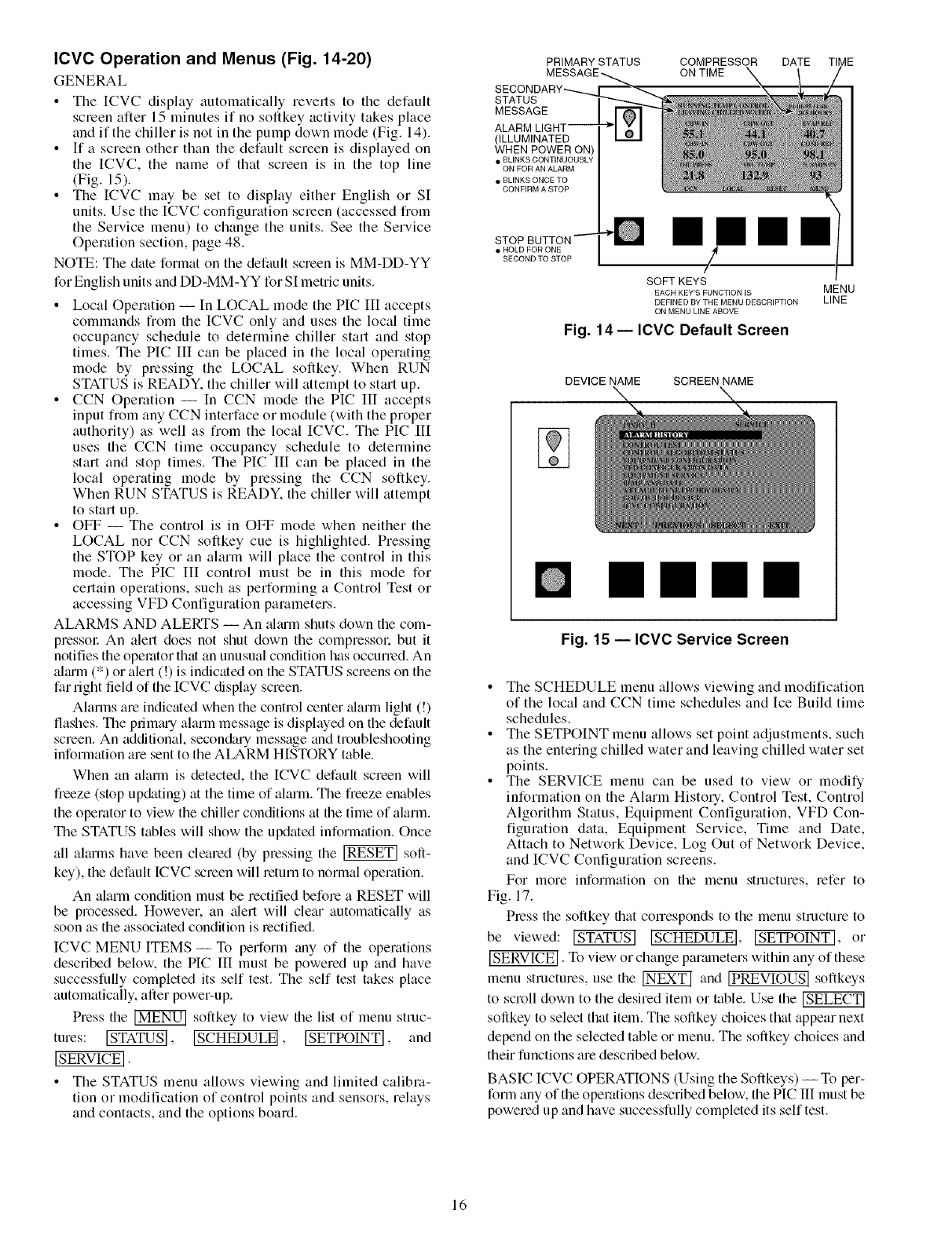
ICVC Operation and Menus (Fig. 14-20)
GENERAL
• The [CVC display automatically reverts to the default
screen after 15 minutes if no softkey activity takes place
and if the chiller is not in the pump down mode (Fig. 14).
• If a screen other than the default screen is displayed on
the ICVC, the name of that screen is in the top line
(Fig. 15).
• The ICVC may be set to display either English or SI
units. Use the ICVC configuration screen (accessed from
the Service menu) to change the units. See the Service
Operation section, page 48.
NOTE: The date format on the default screen is MM-DD-YY
for English units and DD-MM-YY for SI metric units.
• Local Operation -- In LOCAL mode the PIC III accepts
commands fiom the ICVC only and uses the local time
occupancy schedule to determine chiller start and stop
times. The PIC III can be placed in the local operating
mode by pressing the LOCAL softkey. When RUN
STATUS is READY. the chiller will attempt to start up.
• CCN Opelation --In CCN mode the PIC III accepts
input from any CCN interface or module (with the proper
authority) as well as from the local ICVC. The PIC III
uses the CCN time occupancy schedule to determine
start and stop times. The PIC III can be placed in the
local operating mode by pressing the CCN softkey.
When RUN STATUS is READY. the chiller will attempt
to start up.
• OFF -- The control is in OFF mode when neither the
LOCAL nor CCN softkey cue is highlighted. Pressing
the STOP key or an alarm will place the control in this
mode. The PIC III control must be in this mode for
certain operations, such as performing a Control Test or
accessing VFD Configuration parameters.
ALARMS AND ALERTS -- An altu'm shuts down the com-
pressor An alert does not shut down the compressol: but it
notifies the operator that an unusual condition has occurred. An
alarm (*) or alert (!) is indicated on the STATUS screens on the
far right field of the ICVC display screen.
Alarms are indicated when the control center _darm light (!)
flashes. The primtuy alarm message is displayed on the default
screen. An additional, secondary message and troubleshooting
information are sent to the ALARM HISTORY table.
When an alarm is detected, the ICVC default screen will
fieeze (stop up&_ting) at the time of alarm. The freeze enables
the operator to view the chiller conditions at the time of alarm.
The STATUS tables will show the updated information. Once
all aimms have been cleared (by pressing the _ soft-
key), the default ICVC screen will return to normal operation.
An alarm condition must be rectified before a RESET will
be processed. However. an _dert will clear automatically as
soon as the associated condition is rectified.
ICVC MENU ITEMS -- To perform any of the operations
described below, the PIC III must be powered up and have
successfully completed its self test. The self test takes place
automatically, after power-up.
Press the _ softkey to view the list of menu struc-
tures: _, [SCHEDULE], LSETPOINT], and
[SERVICEI.
• The STATUS menu allows viewing and limited calibra-
tion or modification of control points and sensors, relays
and contacts, and the options board.
PRIMARY STATUS
STATUS
MESSAGE
(ILLUMINATED
WHEN POWER ON)
• BLINKS CONTINUOUSLY
ON FOR AN ALARM
• BLINKS ONCE TO
CONFIRM A STOP
COMPRESSOR DATE
ON TIME
• HOLD FOR ONE
SECOND TO STOP
mmmm
/
/
SOFT KEYS
EACH KEY'S FUNCTION IS MENU
DEFINED BY THE MENU DESCRIPTION LINE
ON MENU LINE ABOVE
Fig. 14-- ICVC Default Screen
DEVICE NAME SCREEN NAME
mmm
Fig. 15 -- ICVC Service Screen
• The SCHEDULE menu allows viewing and modification
of the local and CCN time schedules and Ice Build time
schedules.
• The SETPOINT menu allows set point adjustments, such
as the entering chilled water and leaving chilled water set
points.
• The SERVICE menu can be used to view or modify
information on the Alarm History, Control Test, Control
Algorithm Status, Equipment Configuration, VFD Con-
figuration data, Equipment Service, Time and Date,
Attach to Network Device, Log Out of Network Device,
and ICVC Configuration screens.
For more information on the menu structures, refer to
Fig. 17.
Press the softkey that corresponds to the menu structure to
be viewed: _ ISCHEDULEI,[SE OINTI, or
[SERVICE]. To view or change parmneters within any of these
menu structures, use the _ and [PREVIOUS[ softkeys
to scroll down to the desired item or table. Use the
softkey to select that item. The softkey choices that appear next
depend on the selected table or menu. The softkey choices and
their functions are described below.
BASIC ICVC OPERATIONS (Using the Softkeys) -- To per-
form any of the operations described below, the PIC III must be
powered up and have successfully completed its self test.
16
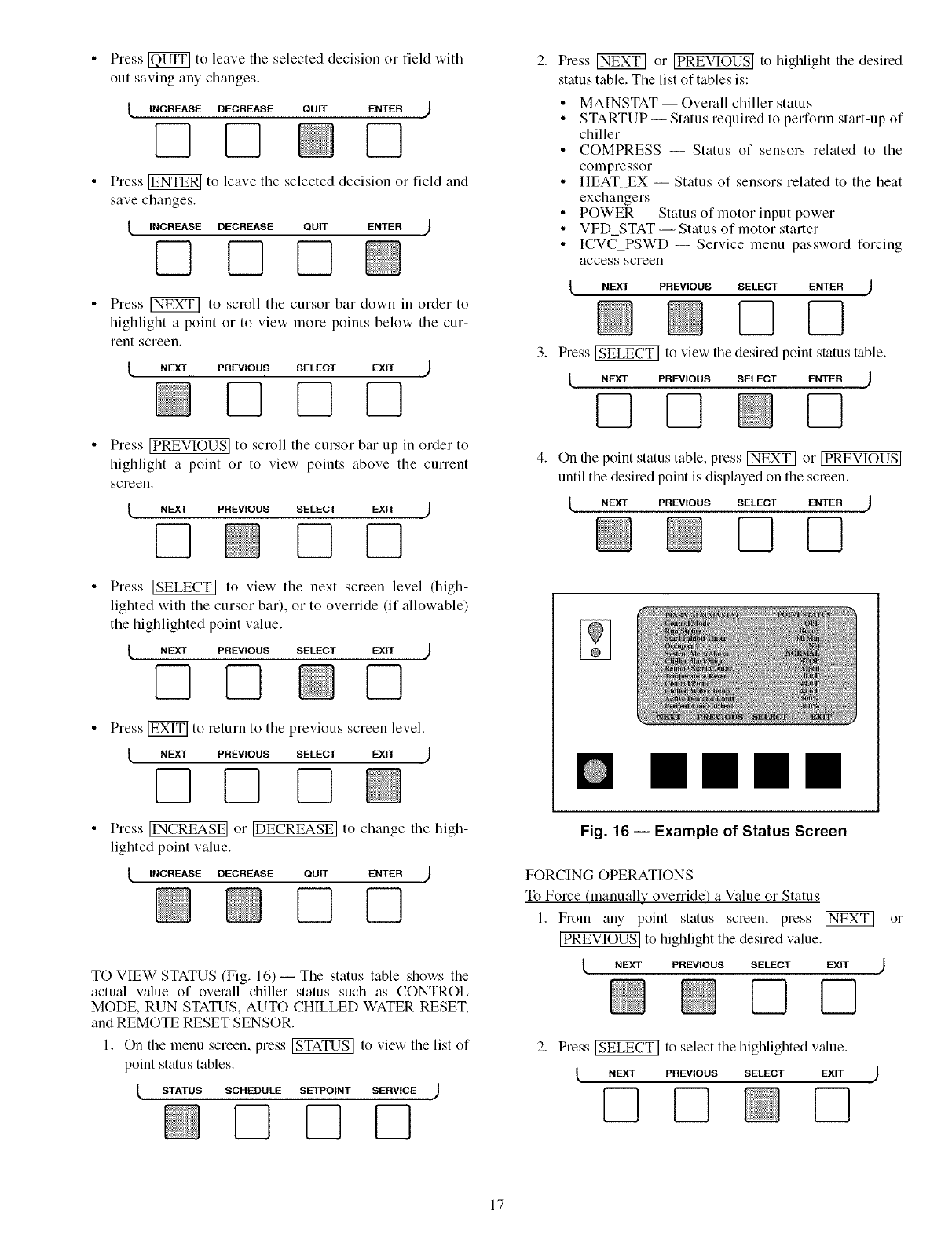
Press _ to leave tile selected decision or field with-
out saving any changes.
_, INCREASE DECREASE QUIT ENTER J
D
Press _ to leave tile selected decision or field and
save changes.
lINCREASE DECREASE QUIT ENTER J
71QD
Press _ to scroll tile cursor bar down in order to
highlight a point or to view more points below the cur-
rent screen.
_, NEXT PREVIOUS SELECT
Press [PREVIOUS[ to scroll tile cursor bar up in order to
highlight a point or to view points above tile current
screen.
NEXT PREVIOUS SELECT
Q
Press _ to view tile next screen level (high-
lighted with the cursor bar), or to override (if allowable)
the highlighted point value.
_, NEXT PREVIOUS SELECT EXIT )
7] Q D
Press _ to return to tile previous screen level.
/ NEXTPREV,OUSSELECTEX,T )
Press ]INCREASE] or IDECREASEI
lighted point value.
INCREASE DECREASE QUIT
N]
to change tile high-
ENTER
7!
TO VIEW STATUS (Fig. 16) -- The status table shows the
actual v_flue of overall chiller status such as CONTROL
MODE, RUN STATUS, AUTO CHILLED WATER RESET.
and REMOTE RESET SENSOR.
I. On tile menu screen, press _ to view tile list of
point status tables.
/STATUS SCHEDULE SETPOINT SERVICE J
Press _ or IPREVIOUSI to highlight the desired
status table. The list of tables is:
•MAINSTAT-- Overall chiller status
•STARTUP-- Status required to perform start-up of
chiller
• COMPRESS -- Status of sensors related to the
compressor
•HEAT_EX -- Status of sensors related to the heat
exchangers
• POWER -- Status of motor input power
•VFD_STAT-- Status of motor starter
• ICVC PSWD -- Service menu password fDrcing
access screen
_, NEXT PREVIOUS SELECT ENTER ,_
Press _ to view the desired point status table.
t NEXT PREVIOUS SELECT ENTER ,_
D
On the point status table, press _ or [PREVIOUS]
until tile desired point is displayed on tile screen.
L NEXT PREVIOUS SELECT ENTER ,J
Q7!
mmmm
Fig. 16 -- Example of Status Screen
FORCING OPERATIONS
TD Force (manually ovelTide) a Value or Status
I. From any point status screen, press _ or
[PREVIOUS] to highlight the desired value.
lNEXT PREVIOUS SELECT EXIT )
QD
Press _ to select tile highlighted v_due.
NEXT PREVIOUS SELECT EXIT
7]
17
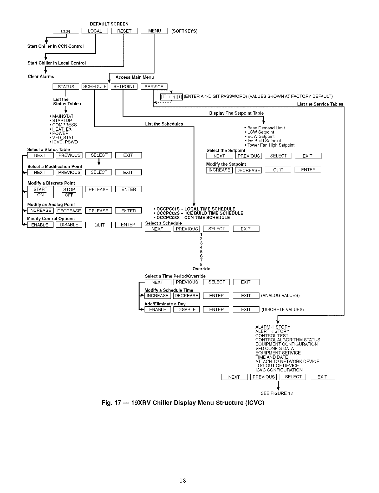
I CCN][
__I-
Start Chiller In CCN Control
DEFAULT SCREEN
LOCAL ] [ RESET II MENU ] (SOFTKEYS)
Start Chiller in Local Control
/
Clear Alarms _Access Main Menu
T
[ STATUS ][SCHEDULE] Es l I SERVICE ]
I
List the
Status Tables
•MAINSTAT
• STARTUP
• COMPRESS
• HEAT EX
• POWER
• VFD STAT
• ICV(_PSWD
Select a Statue Table
NEXT ]1PREVIOUS] [ SELECT ] [ EXIT
!
Select a Modification Point
NEXT ][ PREVIOUS] [ SELECT ] E EXIT
-'_ (ENTER A 4-DIGIT PASSWORD) (VALUES SHOWN AT FACTORY DEFAULT)
...... List the Service Tables
Display The Setpoint Table
List the Schedules
Modify aDiscrete Point
_,_ START ]ON STOP ] [ RELEASE ] [ ENTEROFF
Modify an Analog Point
INCREASE] IDECREASE] [ RELEASE ] E ENTER
Modify Control Options
ENABLE 11 DISABLE ] [ QUIT I [ ENTER
• Base Demand Limit
• LCW Setpoint
• ECW Setpoint
• Ice Build Setpoint
• Tower Fan High Setpcint
Select the Setpoint
[ N_ ][_-EVIOUS] [ SELECT I [
Modify the Setpoint
[INCREASEI[DECREASEII QUIT ] [
• OCCPC01S - LOCAL TIME SCHEDULE
• OCCPC02S - ICE BUILD TIME SCHEDULE
• OCCPC03S - CCN TIME SCHEDULE
Select a Schedule
1[ NEXT ][ PREVIOUS] I SELECT ] [ EXIT
1
2
3
4
5
6
7
8
Override
[NEXT
EXIT ]
EXIT ] (ANALOG VALUES)
EXIT ]
ENTER ]
Select a Time Period/Override
NEX T SELECT ][
e@ I ENTER][
aDay
[ DISABLE ]1 ENTER 1[ EXIT ] (DISCRETE VALUES)
ALARM HISTORY
ALERT HISTORY
CONTROL TEST
CONTROL ALGORITHM STATUS
EQUIPMENT CONFIGURATION
VFD CONFIG DATA
EQUIPMENT SERVICE
TIME AND DATE
ATTACH TO NETWORK DEVICE
LOG OUT OF DEVICE
ICVC CONFIGURATION
]I PREVIOUS][ SELECT I _
SEE FIGURE 18
Fig. 17 -- 19XRV Chiller Display Menu Structure (ICVC)
18
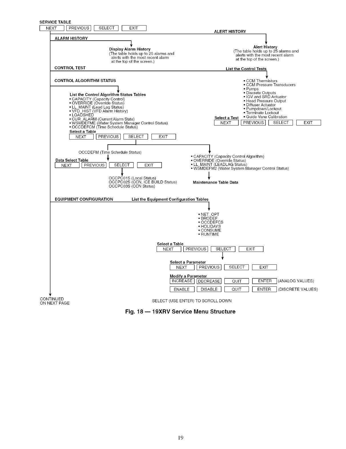
SERVICE TABLE
[ NEXT ][ PREVIOUS] [
ALARM HISTORY
CONTROL TEST
CONTINUED
ON NEXT PAGE
SELECT ] [ EXIT I
Display Alarm History
(The table holds up to 25 alarms and
alerts with the most recent alarm
at the top of the screen.)
ALERT HISTORY !
Alert History
(The table holds up to 25 alarms and
alerts with the most recent alarm
at the top of the screen,)
List the Control Tests
CONTROL ALGORITHM STATUS
List the Control Algorithm Status Tables
• CAPACITY (Capacity Control)
• OVERRIDE (Override Status)
• LL MAINT (Lead Lag Status)
• VFD HIST (VFD Alarm History)
• LOADSHED
• CURALARM (Current Alarm State)
• CCM Thermistors
• CCM Pressure Transducers
• Pumps
• Discrete Outputs
• IGV and SRD Actuator
• Head Pressure Output
• Diffuser Actuator
• Pumpdown/Lockout
• Terminate Lockout
Select a Test • Guide Vane Calibration
] NEXT I[PREVIOus]E SELECT][ EXIT ]• WSMDEFME (Water System Manager Control Status)
• OCCDEFCM (Time Schedule Status)
Select a Table
[NEXT ]EPREVIOUS]I SELECT ][ EXIT ]
I
I
OCCDEFM (Time Schedule Status)
/
Data Select Table
INEXT ][PREVIOus]E SELECT ] [ EXIT ]
I
OCCPC01S (Local Status)
OCCPC02S (CCN, ICE BUILD Status)
OCCPC03S (CCN Status)
• CAPACITY (Capacity Control Algorithm)
• OVERRIDE (Override Status)
• LLMAINT (LEADLAG Status)
• WSMDEFM2 (Water System Manager Control Status)
Maintenance Table Data
EQUIPMENT CONFIGURATION List the Equipment Configuration Tables
• NET OPT
• BRODEF
•OCCDEFCS
• HOLIDAYS
• CONSUME
• RUNTIME
Select a Table
E NEXT ][ PREVIOUS][ SELECT ] [ EXIT
Select a Parameter
[ NEXT ][PREVIOUS] [ SELECT ]
Modify a Parameter
[INCREASE] [DECREASE] [ QUIT ]
[ ENABLE ][ DISABLE ] [ QUIT ]
]
EXIT
ENTER
ENTER
SELECT (USE ENTER) TO SCROLL DOWN
I
](ANALOG VALUES)
I (DISCRETE VALUES)
Fig. 18 -- 19XRV Service Menu Structure
19
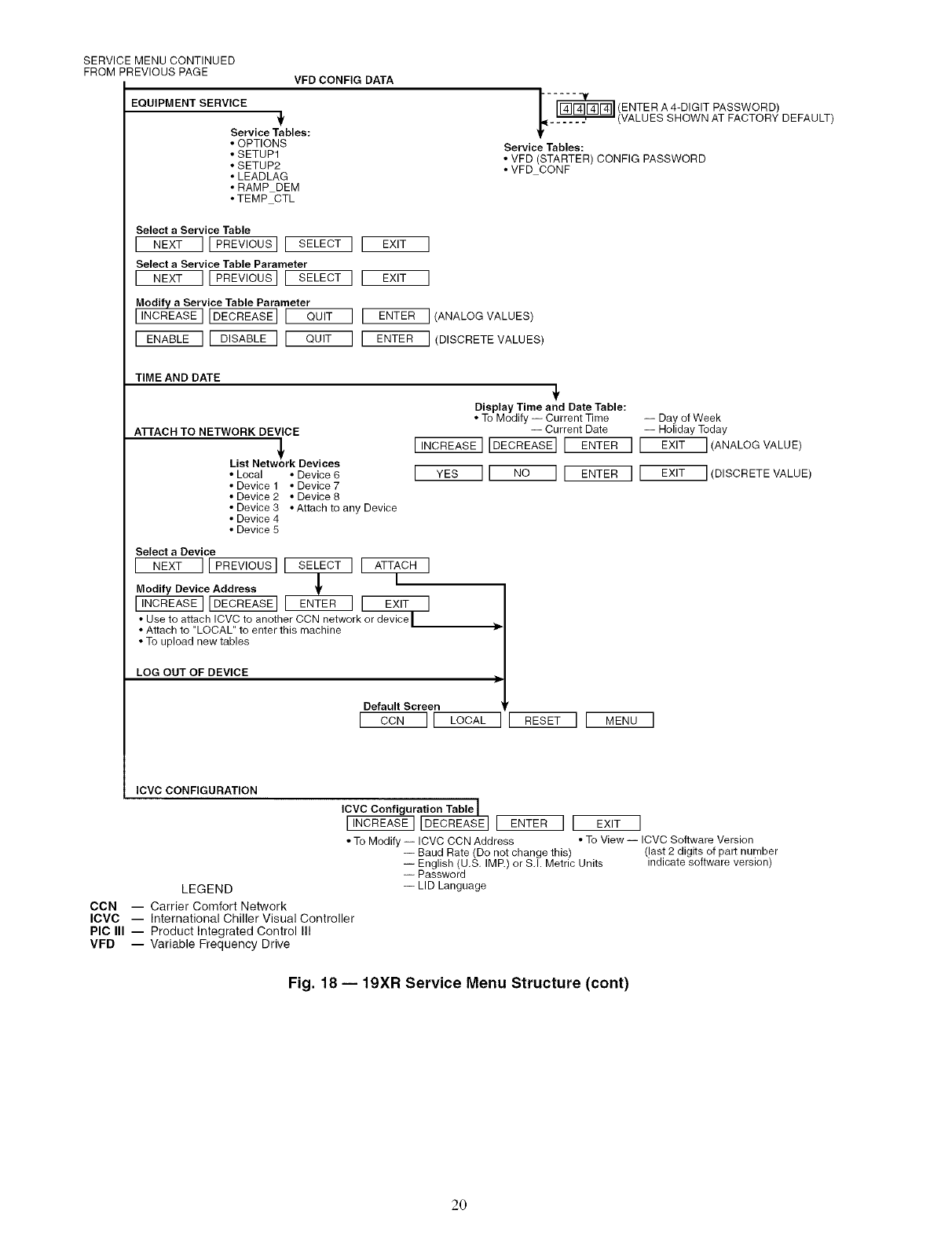
SERVICE MENU CONTINUED
FROM PREVIOUS PAGE VFD CONFIG DATA
EQUIPMENT SERVICE
Service Tables:
•OPTIONS
• SETUPt
• SETUP2
• LEADLAG
• RAMP DEM
• TEMP CTL
--_ (ENTER A 4-DIGIT PASSWORD)
(VALUES SHOWN AT FACTORY DEFAULT)
Service Tables:
• VFD (STARTER) CONFIG PASSWORD
• VFD CONF
Select a Service Table
[NEXT ] IPREVIouslI SELECTI E EXIT l
Select a Service Table Parameter
[NEXT ] I PREVIOUS] I SELECT I E EXit ]
vice Table Parameter
I_AS_] I QUIT ] [ ENTER ] (ANALOG VALUES)
[ ENABLE ] E DISABLE ] IQUIT ] E ENTER ](DISCRETE VALUES)
TIME AND DATE
A'I-rACH TO NETWORK DEVICE
List NetJrk Devices
• Local • Device 6
• Device 1 • Device 7
• Device 2 • Device 8
• Device 3 • Attach to any Device
• Device 4
• Device 5
Display Time and Date Table:
• To Modify -- Current Time -- Day of Week
-- Current Date -- Holiday Today
[INCREASEI[DECREASE]I ENTER ] I EXIT I(ANALOG VALUE)
[ YES I[ NO ] IENTER ] I EXIT I(DISCRETE VALUE)
Select a Device
[ NEXT ]1PREVIOUSI[ SELECT I I ATTACH ]
Modify Device Address _ [
[INCREASE]IDECREASE]I ENTER I E EXIT ]
• Use to attach ICVC to another CCN network or device/
• Attach to "LOCAL" to enter this machine /
• To upload new tables
LOG OUT OF DEVICE
Default Screen
[ CON ]1 LOCAL I[ RESET II MENU l
ICVC CONFIGURATION
ICVC Configuration Table I[ENTER ] [ EXIT ]
• To Modify -- ICVC CCN Address • To View -- ICVC Software Version
(last 2 digits of part number
indicate software version)
-- Baud Rate (Do not change this)
-- English (U.S. IMP.) or S.I. Metric Units
-- Password
-- LID Language
LEGEND
CCN -- Carrier Comfort Network
ICVC -- International Chiller Visual Controller
PIC III -- Product Integrated Control III
VFD -- Variable Frequency Drive
Fig. 18 -- 19XR Service Menu Structure (cont)
20
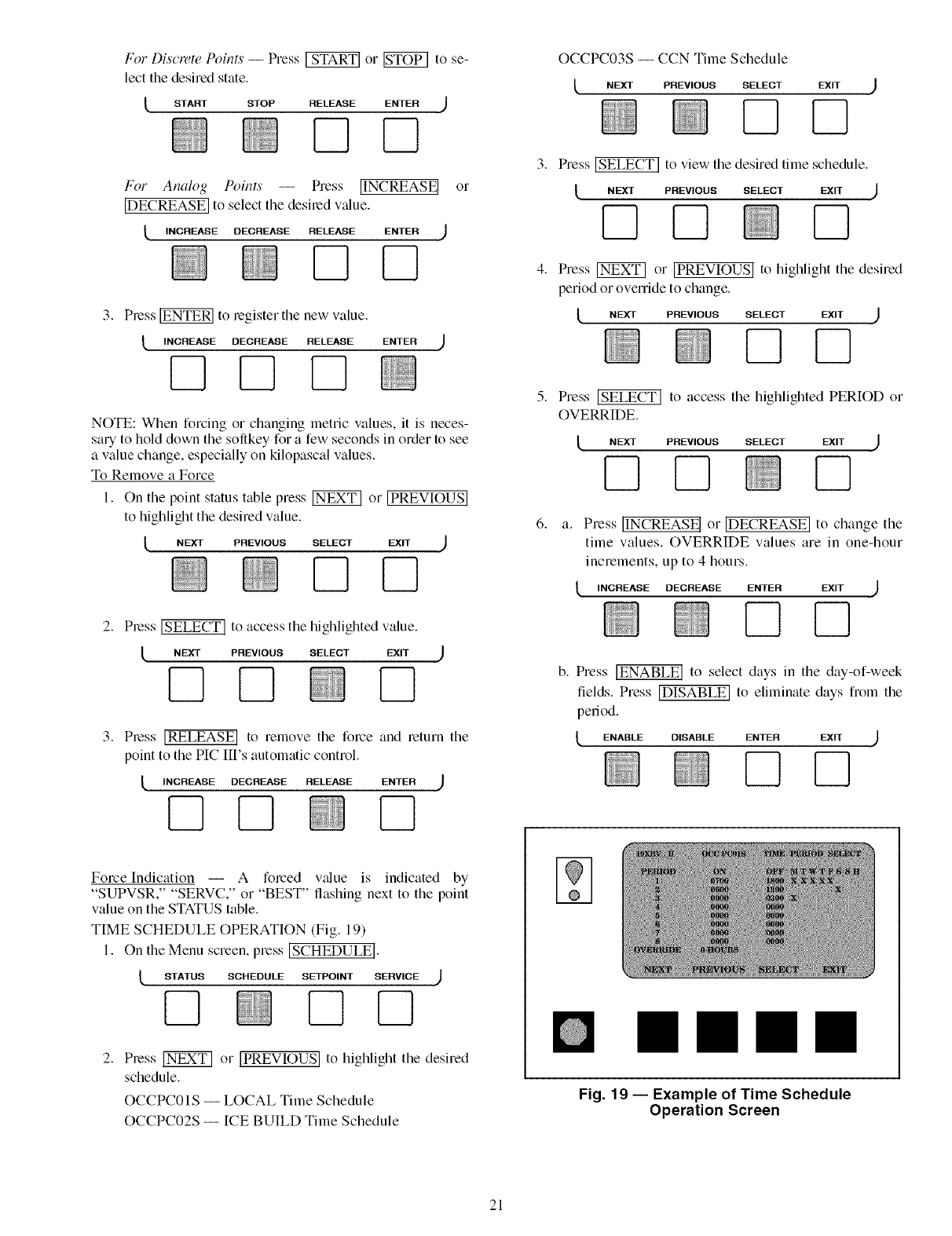
For Discrete Poin_ -- Press _ or _ to se-
lect the desired state.
lSTART STOP RELEASE ENTER )
For Analog Poin_ -- Press IINCREASEI
[DECREASE] to select tile desiled value.
_, INCREASE DECREASE RELEASE ENTER )
or
3. Press _ to legister the new value.
INCREASE DECREASE RELEASE ENTER
NOTE: When forcing or changing metric values, it is neces-
salTto hold down the sollkey for a few seconds in order to see
a value change, especially on kilopascal values.
To Remove a Force
I. On tile point status table press _ or IPREVIOUS]
to highlight the desired value.
lNE_ PREVIOUSSELECT EX. )
2. Pless _ to access tile highlighted value.
NEXT PREVIOUS SELECT EXIT
D
3. Pless [RELEASE] to remove tile force and return tile
point to the PIC III's automatic control.
t INCREASE DECREASE RELEASE ENTER ,]
DD D
Force Indication -- A forced value is indicated by
"SUPVSR," "SERVC," or BEST fla. hmg next to the point
value on the STATUS table.
TIME SCHEDULE OPERATION (Fig. 19)
I. On tile Menu screen, press ]SCHEDULE].
STATUS SCHEDULE SETPOINT SERVICE
D
2. Pless _ or [PREVIOUS] to highlight tile desired
schedule.
OCCPC01S -- LOCAL Time Schedule
OCCPC02S -- ICE BUILD Time Schedule
OCCPC03S -- CCN Time Schedule
NEXT PREVIOUS SELECT EXIT
Press _ to view the desired time schedule.
_, NEXT PREVIOUS SELECT EXIT .)
D
Press _ or IPREVIOUSI to highlight the desired
period or oveMde to change.
[, NEXT PREVIOUS SELECT EXIT .)
Press _ to access tile highlighted PERIOD or
OVERRIDE.
_, NEXT PREVIOUS SELECT EXIT .J
Press IINCREASE I or [DECREASE] to change tile
time values. OVERRIDE values are in one-hour
increments, up to 4 hours.
_INCREASE DECREASE ENTER EXIT .J
b. Press [ENABLE] to select days in the day-of-week
fields. Press IDISABLEI to eliminate days from the
period.
t ENABLED,SA_LEENTER EXIT )
Fig. 19 -- Example of Time Schedule
Operation Screen
21
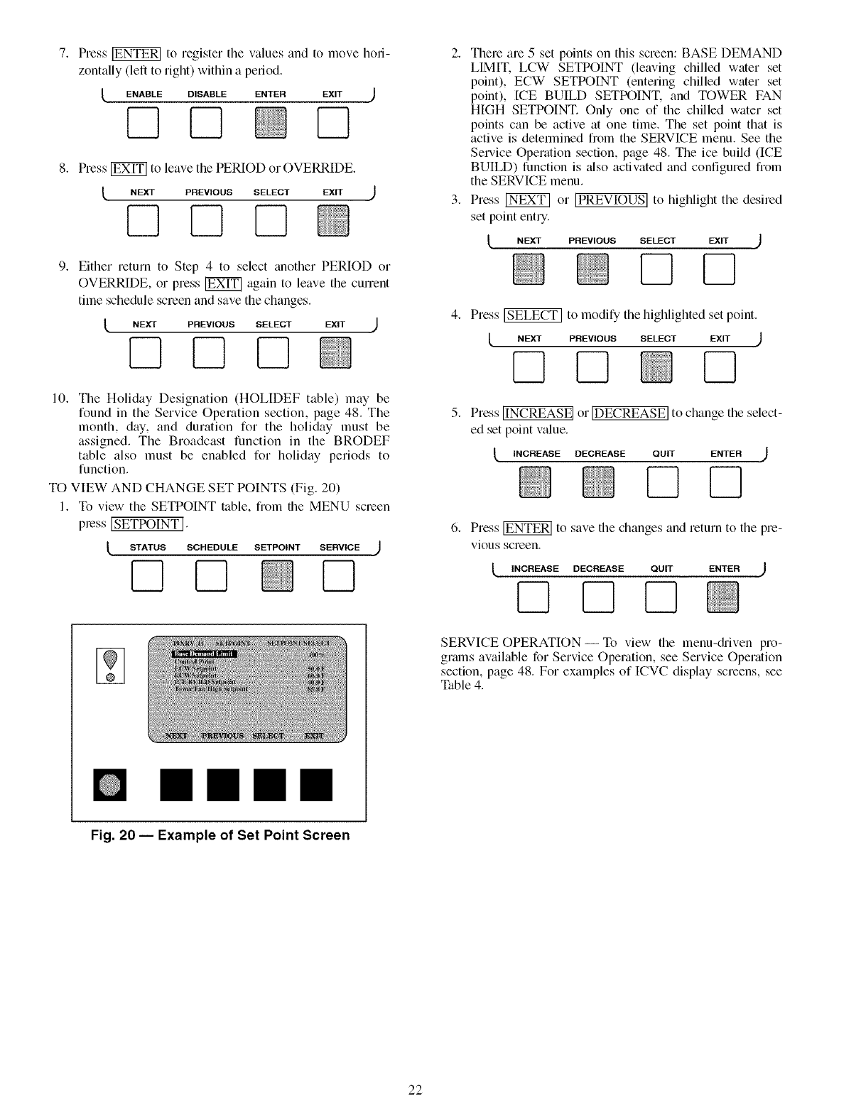
Press _ to register tile values and to move holi-
zontally (left to right) within a pedod.
ENABLE DISABLE ENTER EXIT
7]
Press _ to leave the PERIOD or OVERRIDE.
NEXT PREVIOUS SELECT EXIT
DQQ
Either return to Step 4 to select another PERIOD or
OVERRIDE, or press _ again to leave the current
time schedule screen and save the changes.
tNEXT PREVIOUS SELECT EXIT ,J
10. The Holiday Designation (HOLIDEF table) may be
found in the Service Operation section, page 48. The
month, day, and duration for the holiday must be
assigned. The Broadcast function in the BRODEF
table also must be enabled for holiday periods to
function.
TO VIEW AND CHANGE SET POINTS (Fig. 20)
I. To view the SETPOINT table, fiom the MENU screen
pless ISETPOINT 1.
STATUS SCHEDULE SETPOINT SERVICE )
D
mmmm
2. There are 5 set points on this screen: BASE DEMAND
LIMIT. LCW SETPOINT (leaving chilled water set
point), ECW SETPOINT (entering chilled water set
point), ICE BUILD SETPOINT, and TOWER FAN
HIGH SETPOINT. Only one of the chilled water set
points can be active at one time. The set point that is
active is determined from the SERVICE menu. See the
Service Operation section, page 48. The ice build (ICE
BUILD) function is _flso activated and configured from
the SERVICE menu.
3. Press _ or [PREVIOUS] to highlight the desired
set point entry.
NEXT PREVIOUS SELECT EXIT )
4. Press _ to modify the highlighted set point.
t PREV,OUSSELECT EX,T )
D
5. Press IINCREASEI or IDECREASEI to change the select-
ed set point value.
_, INCREASE DECREASE QUIT ENTER )
6. Press _ to save the changes and return to the pre-
vious screen.
_, INCREASE DECREASE QUIT ENTER )
SERVICE OPERATION- To view the menu-&iven pro-
grams available for Service Operation, see Service Operation
section, page 48. For examples of ICVC display screens, see
Table 4.
Fig. 20 -- Example of Set Point Screen
22
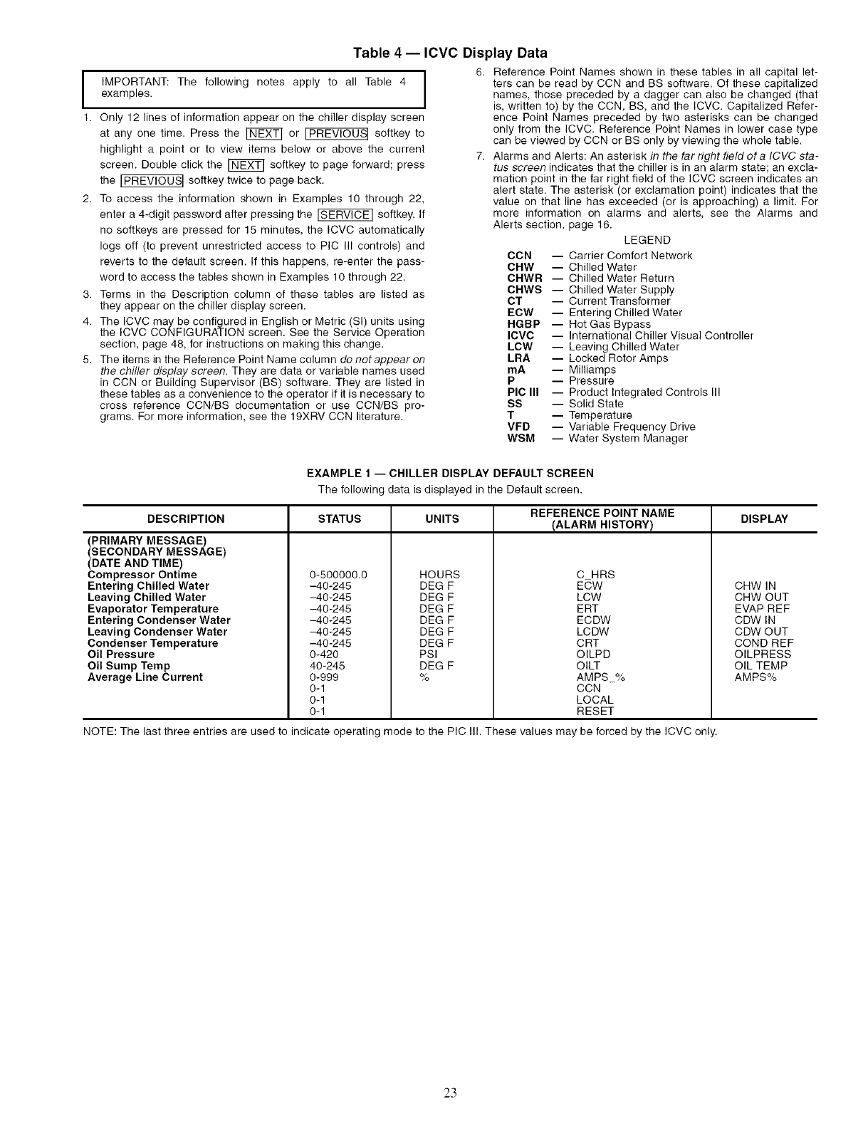
Table 4 -- ICVC Display Data
IIMPORTANT: The following notes apply to all Table 4
examples.
1. Only 12 lines of information appear on the chiller display screen
at any one time. Press the _ or I PREVlOUS I softkey to
highlight a point or to view items below or above the current
screen. Double click the _ softkey to page forward; press
the IPREVIOUS] softkey twice to page back.
2. To access the information shown in Examples 10 through 22,
enter a 4-digit password after pressing the _ softkey. If
no softkeys are pressed for 15 minutes, the ICVC automatically
logs off (to prevent unrestricted access to PIC III controls) and
reverts to the default screen. If this happens, re-enter the pass-
word to access the tables shown in Examples 10 through 22.
3. Terms in the Description column of these tables are listed as
they appear on the chiller display screen.
4. The ICVC may be configured in English or Metric (Sl) units using
the ICVC CONFIGURATION screen. See the Service Operation
section, page 48, for instructions on making this change.
5. The items in the Reference Point Name column do not appear on
the chiller display screen. They are data or variable names used
in CCN or Building Supervisor (BS) software. They are listed in
these tables as a convenience to the operator if it is necessary to
cross reference CCN/BS documentation or use CCN/BS pro-
grams. For more information, see the 19XRV CCN literature.
6. Reference Point Names shown in these tables in all capital let-
ters can be read by CCN and BS software. Of these capitalized
names, those preceded by a dagger can also be changed (that
is, written to) by the CCN, BS, and the ICVC. Capitalized Refer-
ence Point Names preceded by two asterisks can be changed
only from the ICVC. Reference Point Names in lower case type
can be viewed by CCN or BS only by viewing the whole table.
7. Alarms and Alerts: An asterisk in the far right field of a ICVC sta-
tus screen indicates that the chiller is in an alarm state; an excla-
mation point in the far right field of the ICVC screen indicates an
alert state. The asterisk (or exclamation point) indicates that the
value on that line has exceeded (or is approaching) a limit. For
more information on alarms and alerts, see the Alarms and
Alerts section, page 16.
LEGEND
CCN -- Carrier Comfort Network
CHW -- Chilled Water
CHWR -- Chilled Water Return
CHWS -- Chilled Water Supply
CT -- Current Transformer
ECW -- Entering Chilled Water
HGBP -- Hot Gas Bypass
ICVC -- International Chiller Visual Controller
LOW -- Leaving Chilled Water
LRA -- Locked Rotor Amps
mA -- Milliamps
P -- Pressure
PIC III -- Product Integrated Controls III
SS -- Solid State
T-- Temperature
VFD -- Variable Frequency Drive
WSM -- Water System Manager
EXAMPLE 1 -- CHILLER DISPLAY DEFAULT SCREEN
The following data is displayed in the Default screen.
DESCRIPTION STATUS UNITS REFERENCE POINT NAME DISPLAY
(ALARM HISTORY)
(PRIMARY MESSAGE)
(SECONDARY MESSAGE)
(DATE AND TIME)
Compressor Ontime
Entering Chilled Water
Leaving Chilled Water
Evaporator Temperature
Entering Condenser Water
Leaving Condenser Water
Condenser Temperature
Oil Pressure
Oil Sump Temp
Average Line Current
0-500000.0
-40-245
-40-245
-40-245
-40-245
-40-245
-40-245
0-420
40-245
0-999
0-1
0-1
0-1
HOURS
DEG F
DEG F
DEG F
DEG F
DEG F
DEG F
PSI
DEG F
%
C HRS
ECW
LCW
ERT
ECDW
LCDW
CRT
OILPD
OILT
AMPS_%
CCN
LOCAL
RESET
NOTE: The last three entries are used to indicate operating mode to the PIC Ill. These values may be forced by the ICVC only.
CHW IN
CHW OUT
EVAP REF
CDW IN
CDW OUT
COND REF
OILPRESS
OIL TEMP
AMPS%
23
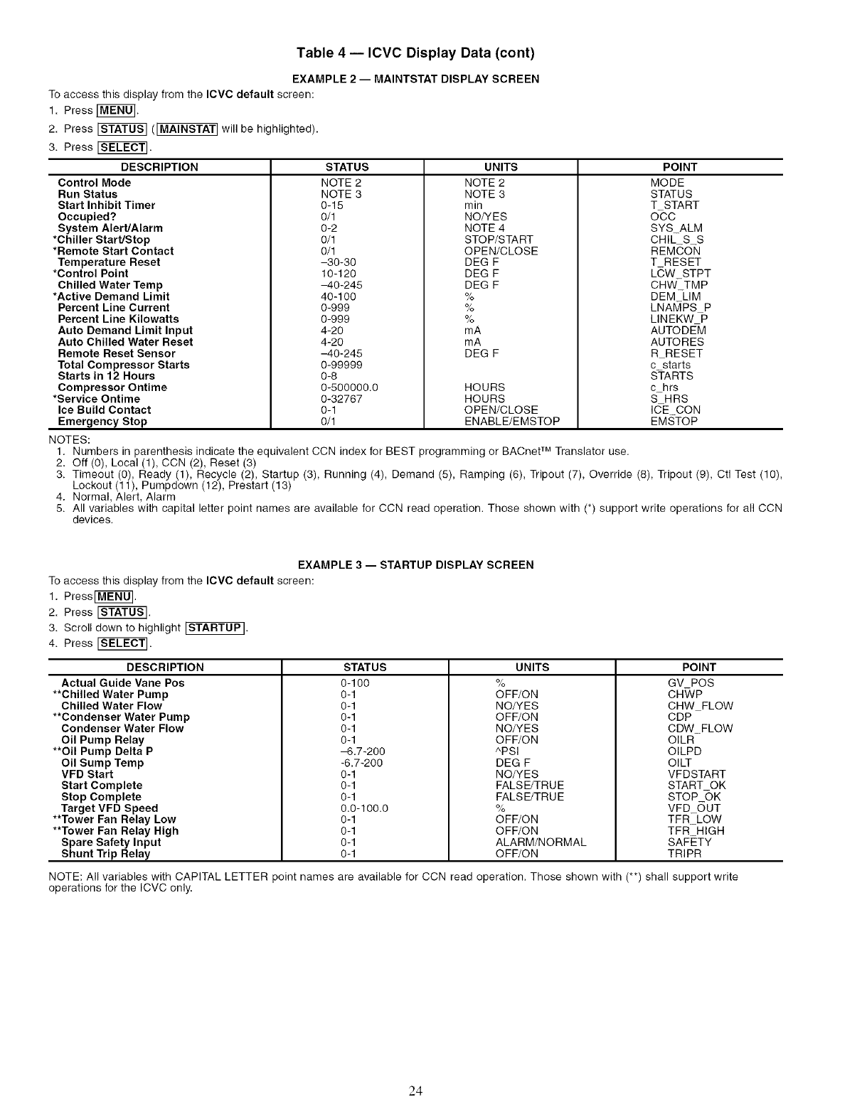
Table 4 -- ICVC Display Data (cont)
EXAMPLE 2 -- MAINTSTAT DISPLAY SCREEN
To access this display from the ICVC default screen:
1. Press [MEffO_.
2. Press _ (IMAINSTAT] will be highlighted).
3. Press _.
DESCRIPTION STATUS UNITS
Control Mode NOTE 2 NOTE 2
Run Status NOTE 3 NOTE 3
Start Inhibit Timer 0-15 rain
Occupied'?. 0/1 NO/YES
System Alert/Alarm 0-2 NOTE 4
*Chiller Start/Stop 0/1 STOP/START
*Remote Start Contact 0/1 OPEN/CLOSE
POINT
MODE
STATUS
T START
O-CO
SYS_ALM
CHIL_S_S
REMCON
Temperature Reset
*Control Point
Chilled Water Temp
*Active Demand Limit
Percent Line Current
Percent Line Kilowatts
Auto Demand Limit Input
Auto Chilled Water Reset
Remote Reset Sensor
Total Compressor Starts
Starts in 12 Hours
Compressor Ontime
*Service Ontime
-30-30
10-120
-40-245
40-100
0-999
0-999
4-20
4-20
-40-245
0-99999
0-8
0-500000.0
0-32767
DEG F
DEG F
DEG F
%
%
%
mA
mA
DEG F
HOURS
HOURS
T RESET
LCW STPT
CHW_TMP
DEM LIM
LNAMPS P
LINEKW P
AUTODEM
AUTORES
R RESET
c starts
S-TARTS
c hrs
S-HRS
Ice Build Contact 0-1 OPEN/CLOSE lEE CON
Emergency Stop 0/1 ENABLE/EMSTOP EMSTOP
NOTES:
1. Numbers in parenthesis indicate the equivalent CCN index for BEST programming or BACnet TM Translator use.
2. Off (0), Local (1), CCN (2), Reset (3)
3. Timeout (0), Ready (1), Recycle (2), Startup (3), Running (4), Demand (5), Ramping (6), Tripout (7), Override (6), Tripout (9), Ctl Test (10),
Lockout (11), Pumpdown (12), Prestart (13)
4. Normal, Alert, Alarm
5. All variables with capital letter point names are available for CCN read operation. Those shown with (*) support write operations for all CCN
devices.
EXAMPLE 3 -- STARTUP DISPLAY SCREEN
To access this display from the IOVC default screen:
1. Press _MENO].
2. Press ISTATOS].
3. Scroll down to highlight [STARTUP].
4. Press _SEEECT].
DESCRIPTION
Actual Guide Vane Pos
**Chilled Water Pump
Chilled Water Flow
**Condenser Water Pump
Condenser Water Flow
Oil Pump Relay
**Oil Pump Delta P
Oil Sump Temp
VFD Start
Start Complete
Stop Complete
Target VFD Speed
**Tower Fan Relay Low
**Tower Fan Relay High
Spare Safety Input
Shunt Trip Relay
STATUS
0-100
0-1
0-1
0-1
0-1
0-1
-6.7-200
-6,7-200
0-1
0-1
0-1
0,0-100.0
0-1
0-1
0-1
0-1
UNITS
%
OFF/ON
NO/YES
OFF/ON
NO/YES
OFF/ON
^PSI
DEG F
NO/YES
FALSE/TRUE
FALSE/TRUE
%
OFF/ON
OFF/ON
ALARM/NORMAL
OFF/ON
POINT
GV POS
CH_/P
CHW FLOW
CDP
CDW_FLOW
OILR
OILPD
OILT
VFDSTART
START OK
STOP ()K
VFD_OUT
TFR_LOW
TFR HIGH
SAFETY
TRIPR
NOTE: All variables with CAPITAL LETTER point names are available for CCN read operation. Those shown with (**) shall support write
operations for the ICVC only.
24
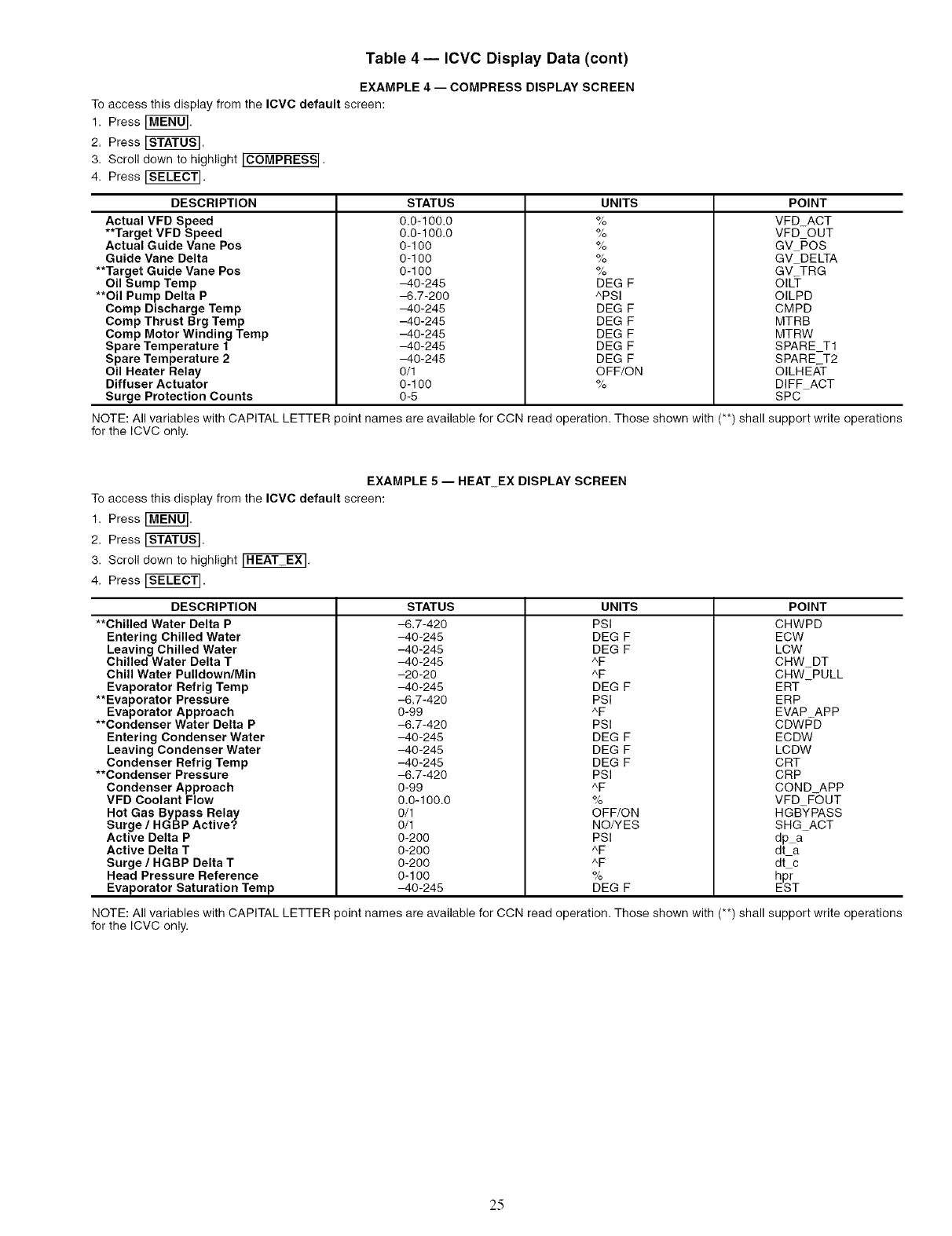
Table 4 -- ICVC Display Data (cont)
EXAMPLE 4-- COMPRESS DISPLAY SCREEN
To access this display from the ICVC default screen:
1. Press _MEN0].
2. Press [S_TOS].
3. Scroll down to highlight ICOMPRESS I .
4. Press [SELECt.
DESCRIPTION
Actual VFD Speed
**Target VFD Speed
Actual Guide Vane Pos
Guide Vane Delta
**Target Guide Vane Pos
Oil Sump Temp
**Oil Pump Delta P
Comp Discharge Temp
Comp Thrust Brg Temp
Comp Motor Winding Temp
Spare Temperature 1
Spare Temperature 2
Oil Heater Relay
Diffuser Actuator
Surge Protection Counts
NOTE: All variables with CAPITAL LETTER
for the ICVC only.
STATUS
0.0-100.0
0.0-100.0
0-100
0-100
0-100
-40-245
-6.7-200
-40-245
-40-245
-40-245
-40-245
-40-245
0/1
0-100
0-5
UNITS
%
%
%
%
%
DEG F
^PSI
DEG F
DEG F
DEG F
DEG F
DEG F
OFF/ON
%
POINT
VFD_ACT
VFD OUT
GV POS
GV DELTA
GV TRG
OIL_-
OILPD
CMPD
MTRB
MTRW
SPARE_T1
SPARE T2
OILHE/_T
DIFF ACT
SPC
)oint names are available for CCN read operation. Those shown with (**) shall support write operations
EXAMPLE 5 -- HEAT_EX DISPLAY SCREEN
To access this display from the ICVC default screen:
1. Press _MEN0].
2. Press [STATOS].
3. Scroll down to highlight _.
4. Press [SEL_T].
DESCRIPTION
**Chilled Water Delta P
Entering Chilled Water
Leaving Chilled Water
Chilled Water Delta T
Chill Water Pulldown/Min
Evaporator Refrig Temp
**Evaporator Pressure
Evaporator Approach
**Condenser Water Delta P
Entering Condenser Water
Leaving Condenser Water
Condenser Refrig Temp
**Condenser Pressure
Condenser Approach
VFD Coolant Flow
Hot Gas Bypass Relay
Surge /HGBP Active?
Active Delta P
Active Delta T
Surge /HGBP Delta T
Head Pressure Reference
Evaporator Saturation Temp
STATUS
-6.7-420
-40-245
-40-245
-40-245
-20-20
-40-245
-6.7-420
0-99
-6.7-420
-40-245
-40-245
-40-245
-6.7-420
0-99
0.0-I00.0
0/I
0/I
0-200
0-200
0-200
0-100
-40-245
UNITS
PSI
DEG F
DEG F
^F
^F
DEG F
PSI
^F
PSI
DEG F
DEG F
DEG F
PSI
^F
%
OFF/ON
NO/YES
PSI
^F
^F
%
DEG F
POINT
CHWPD
ECW
LCW
CHW_DT
CHW_PULL
ERT
ERP
EVAP APP
CDWPD
ECDW
LCDW
CRT
CRP
COND APP
VFD F-OUT
HGB-YPASS
SHG ACT
dp a
dt a
dt c
hpr
EST
NOTE: All variables with CAPITAL LETTER point names are available for CCN read operation. Those shown with (**) shall support write operations
for the ICVC only.
2.5
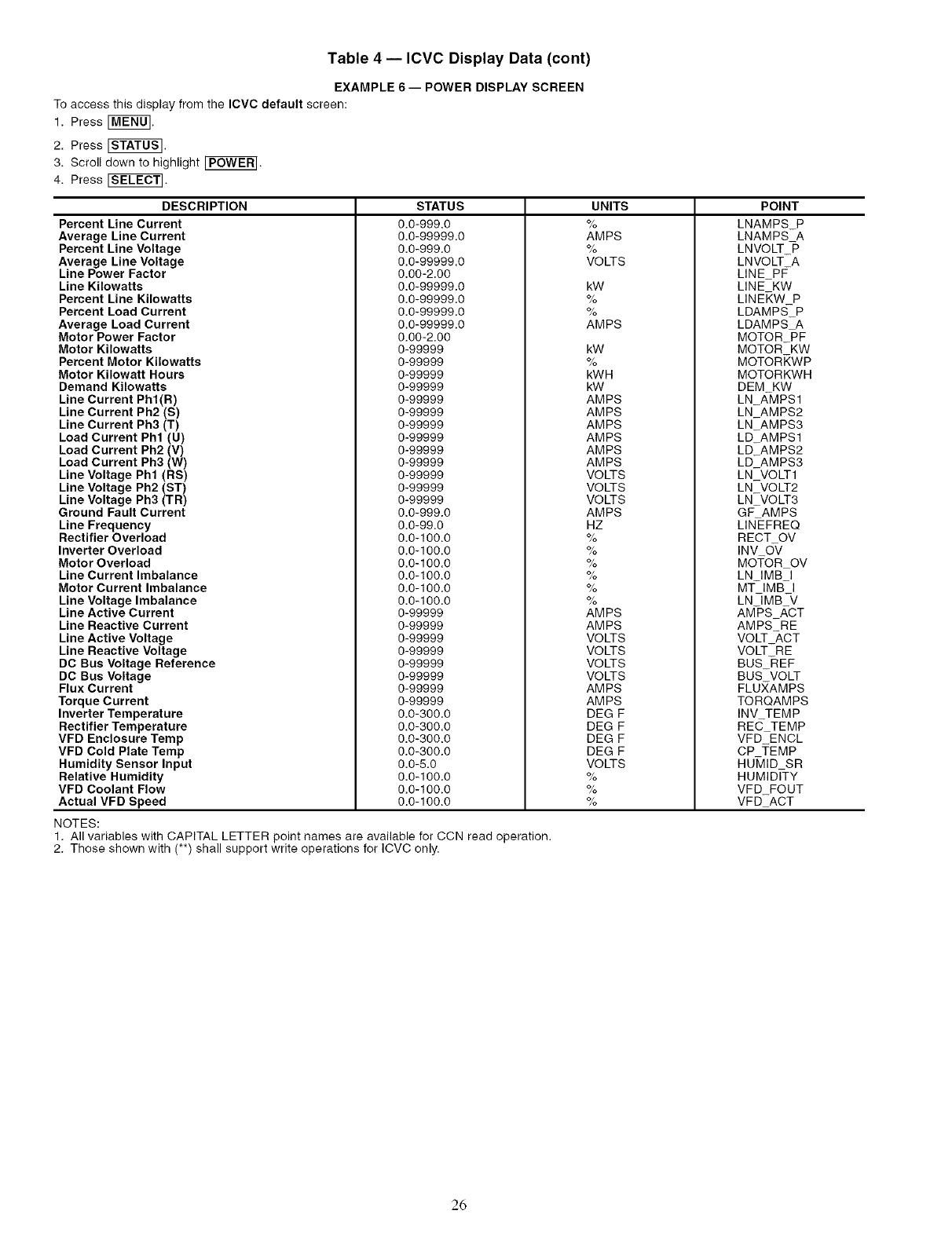
Table 4 -- ICVC Display Data (cont)
EXAMPLE 6-- POWER DISPLAY SCREEN
To access this display from the ICVC default screen:
1. Press [MEN0].
2. Press ISTATOS].
3. Scroll down to highlight _P6WER].
4. Press _SE_CT].
DESCRIPTION
Percent Line Current
Average Line Current
Percent Line Voltage
Average Line Voltage
Line Power Factor
Line Kilowatts
Percent Line Kilowatts
Percent Load Current
Average Load Current
Motor Power Factor
Motor Kilowatts
Percent Motor Kilowatts
Motor Kilowatt Hours
Demand Kilowatts
Line Current Phf(R)
Line Current Ph2 (S)
Line Current Ph3 (T)
Load Current Phl (U)
Load Current Ph2 (V)
Load Current Ph3 (W)
Line Voltage Phl (RS)
Line Voltage Ph2 (ST)
Line Voltage Ph3 (TR)
Ground Fault Current
Line Frequency
Rectifier Overload
Inverter Overload
Motor Overload
Line Current Imbalance
Motor Current Imbalance
Line Voltage Imbalance
Line Active Current
Line Reactive Current
Line Active Voltage
Line Reactive Voltage
DC Bus Voltage Reference
DC Bus Voltage
Flux Current
Torque Current
Inverter Temperature
Rectifier Temperature
VFD Enclosure Temp
VFD Cold Plate Temp
Humidity Sensor Input
Relative Humidity
VFD Coolant Flow
Actual VFD Speed
STATUS
0.0-999.0
0.0-99999.0
0.0-999.0
0.0-99999.0
0.00-2.00
0.0-99999.0
0.0-99999.0
0.0-99999.0
0.0-99999.0
0.00-2.00
0-99999
0-99999
0-99999
0-99999
0-99999
0-99999
0-99999
0-99999
0-99999
0-99999
0-99999
0-99999
0-99999
0.0-999.0
0.0-99.0
0.0-100.0
0.0-100.0
0.0-100.0
0.0-100.0
0.0-100.0
0.0-100.0
0-99999
0-99999
0-99999
0-99999
0-99999
0-99999
0-99999
0-99999
0.0-300.0
0.0-300.0
0.0-300.0
0.0-300.0
0.0-5.0
0.0-100.0
0.0-100.0
0.0-100.0
UNITS
%
AMPS
%
VOLTS
kW
%
%
AMPS
kW
%
kWH
kW
AMPS
AMPS
AMPS
AMPS
AMPS
AMPS
VOLTS
VOLTS
VOLTS
AMPS
HZ
%
%
%
%
%
%
AMPS
AMPS
VOLTS
VOLTS
VOLTS
VOLTS
AMPS
AMPS
DEG F
DEG F
DEG F
DEG F
VOLTS
%
%
%
POINT
LNAMPS P
LNAMPS A
LNVOLT -P
LNVOLT A
LINE_PF-
LINE KW
LIN EK,W P
LDAMPS_P
LDAMPS A
MOTOR PF
MOTOR KW
MOTORKWP
MOTORKWH
DEM KW
LN A-MPSl
LN_AMPS2
LN AMPS3
LD AMPSl
LD AMPS2
LD_AMPS3
NOTES:
1. All variables with CAPITAL LETTER point names are available for CCN read operation.
2. Those shown with (**) shall support write operations for ICVC only.
LN_VOLT1
LN_VOLT2
LN VOLT3
GF-AMPS
LINEFREQ
RECT OV
INV O-V
MOTOR OV
LN IMB I
MT- IMB- I
LN IMB V
AM-PS_,g,CT
AMPS RE
VOLT ACT
VOLT RE
BUS -REF
BUS VOLT
FLUXAMPS
TORQAMPS
INV TEMP
REC TEMP
VFD ENCL
CP TEMP
HU_]ID SR
HUMIDITY
VFD FOUT
VFD ACT
26
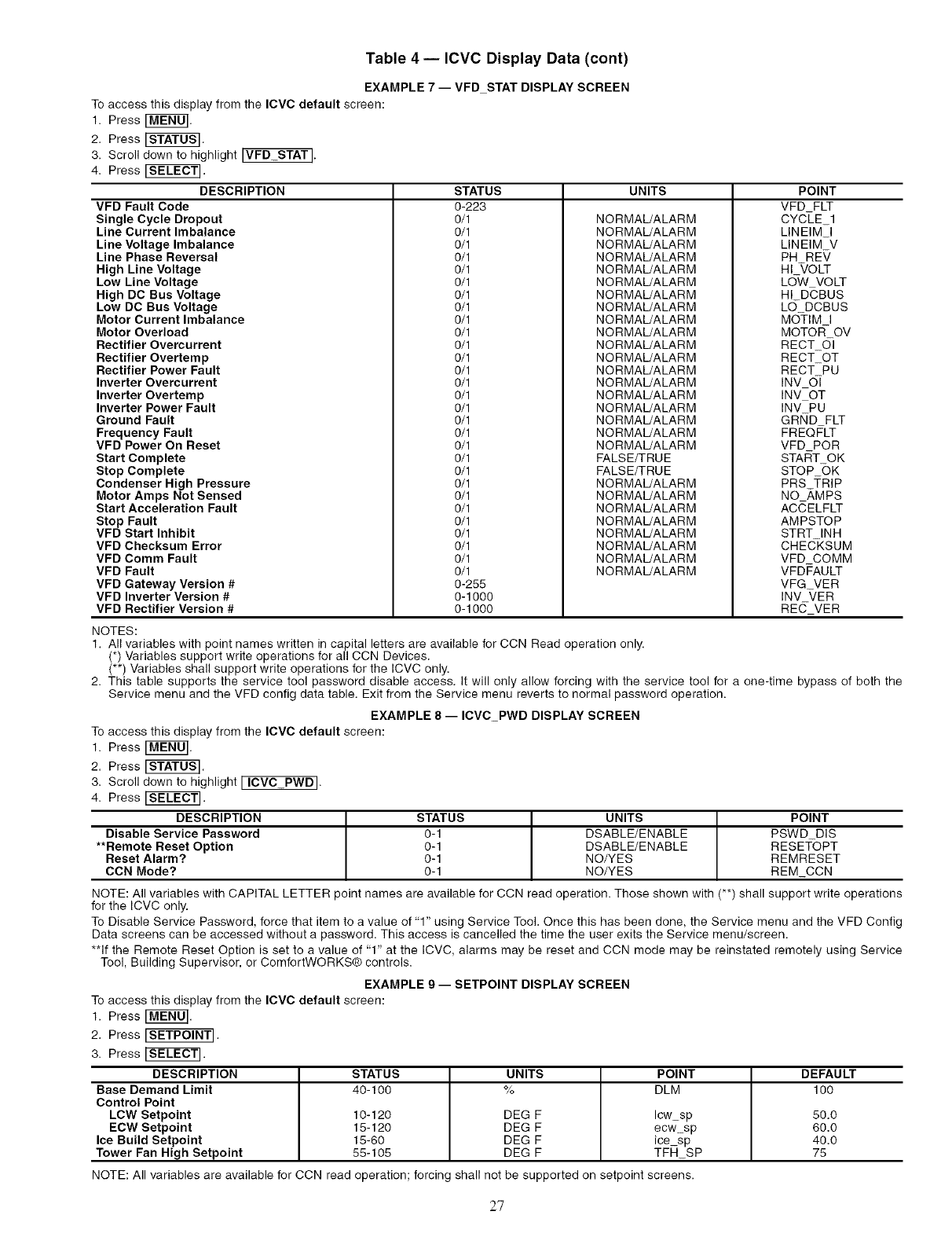
Table 4 -- ICVC Display Data (cont)
EXAMPLE 7 -- VFD STAT DISPLAY SCREEN
To access this display from the ICVC default screen:
1. Press [MEN0].
2. Press [S_T0S].
3. Scroll down to highlight ]VFD STAT].
4. Press [S_EC_.
DESCRIPTION STATUS UNITS POINT
VFD Fault Code
Single Cycle Dropout
Line Current Imbalance
Line Voltage Imbalance
Line Phase Reversal
High Line Voltage
Low Line Voltage
High DC Bus Voltage
Low DC Bus Voltage
Motor Current Imbalance
Motor Overload
Rectifier Overcurrent
Rectifier Overtemp
Rectifier Power Fault
Inverter Overcurrent
Inverter Overtemp
Inverter Power Fault
Ground Fault
Frequency Fault
VFD Power On Reset
Start Complete
Stop Complete
Condenser High Pressure
Motor Amps Not Sensed
Start Acceleration Fault
Stop Fault
VFD Start Inhibit
VFD Checksum Error
VFD Comm Fault
VFD Fault
VFD Gateway Version #
VFD Inverter Version #
VFD Rectifier Version #
0-223
0/1
0/1
0/1
0/1
0/1
0/1
0/1
0/1
0/1
0/1
0/1
0/1
0/1
0/1
0/1
0/1
0/1
0/1
0/1
0/1
0/1
0/1
0/1
0/1
0/1
0/1
0/1
0/1
0/1
0-255
0-1000
0-1000
NORMAL/ALARM
NORMAL!ALARM
NORMAL!ALARM
NORMAL!ALARM
NORMAL!ALARM
NORMAL!ALARM
NORMAL!ALARM
NORMAL!ALARM
NORMAL!ALARM
NORMAL!ALARM
NORMAL!ALARM
NORMAL!ALARM
NORMAL/ALARM
NORMAL!ALARM
NORMAL!ALARM
NORMAL!ALARM
NORMAL!ALARM
NORMAL!ALARM
NORMAL!ALARM
FALSE/TRUE
FALSE/TRUE
NORMAL!ALARM
NORMAL!ALARM
NORMAL!ALARM
NORMAL!ALARM
NORMAL!ALARM
NORMAL!ALARM
NORMAL!ALARM
NORMAL!ALARM
VFD FLT
CYCLE_I
LINEIM I
LINEIM V
PH REV
HI_VOLT
LdW VOLT
HI DCBUS
L(9 DCBUS
MO-TIM I
MOTOR- OV
RECT_C_
RECT OT
RECT PU
INV O]
INV OT
INV PU
GRIND FLT
FREQ#LT
VFD POR
STAtgT OK
STOP OK
PRS TRIP
NO _,MPS
ACCELFLT
AMPSTOP
STRT INH
CHECKSUM
VFD COMM
VFDFAULT
VFG VER
INV _/ER
RECVER
NOTES:
1. All variables with point names written in capital letters are available for CCN Read operation only.
(*) Variables support write operations for all CCN Devices.
(**) Variables shall support write operations for the ICVC only.
2. This table supports the service tool password disable access. It will only allow forcing with the service tool for a one-time bypass of both the
Service menu and the VFD config data table. Exit from the Service menu reverts to normal password operation.
EXAMPLE 8-- ICVC PWD DISPLAY SCREEN
To access this display from the IOVC default screen:
1. Press [MEN0].
2. Press [_AT0S].
3. Scroll down to highlight [ ICVC PWD].
4. Press [_T_T].
DESCRIPTION
Disable Service Password
**Remote Reset Option
Reset Alarm?
CCN Mode?
STATUS
0-1
0-1
0-1
0-1
UNITS POINT
DSABLE/ENABLE PSWD DiS
DSABLE/ENABLE RESE]_OPT
NO/YES REMRESET
NO/YES REM CCN
NOTE: All variables with CAPITAL LETTER point names are available for CCN read operation. Those shown with (**) shall support write operations
for the ICVC only.
To Disable Service Password, force that item to a value of "1" using Service Tool. Once this has been done, the Service menu and the VFD Config
Data screens can be accessed without a password. This access is cancelled the time the user exits the Service menu/screen.
**If the Remote Reset Option is set to a value of "1" at the ICVC, alarms may be reset and CCN mode may be reinstated remotely using Service
Tool, Building Supervisor, or ComfortWORKS® controls.
EXAMPLE g -- SETPOINT DISPLAY SCREEN
To access this display from the ICVC default screen:
1. Press [MEN0].
2. Press [SETPOINT].
3. Press [S_E_].
DESCRIPTION
Base Demand Limit
Control Point
LCW Setpoint
ECW Setpoint
Ice Build Setpoint
Tower Fan High Setpoint
STATUS UNITS POINT DEFAULT
40-100 % DLM 100
10-120 DEG F Icwsp 50.0
15-120 DEG F ecwsp 60.0
15-60 DEG F ice sp 40.0
55-105 DEG F TFH SP 75
NOTE: All variables are available for CCN read operation; forcing shall not be supported on setpoint screens.
27
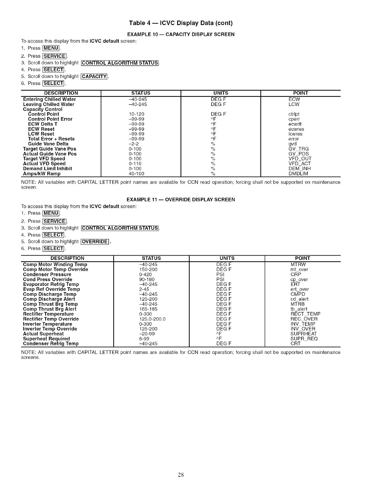
Table 4 -- ICVC Display Data (cont)
EXAMPLE 10- CAPACITY DISPLAY SCREEN
To access this display from the ICVC default screen:
1. Press [MENO].
2. Press _.
3. Scroll down to highlight [CONTROL ALGORITHM STATUS[.
4. Press _SELECf].
5. Scroll down to highlight [CAPACITY].
6. Press _SELECT].
DESCRIPTION
Entering Chilled Water
Leaving Chilled Water
Capacity Control
Control Point
Control Point Error
ECW Delta T
ECW Reset
LCW Reset
Total Error + Resets
Guide Vane Delta
Target Guide Vane Pos
Actual Guide Vane Poe
Target VFD Speed
Actual VFD Speed
Demand Limit Inhibit
Amps/kW Ramp
STATUS
-40-245
-40-245
10-120
-99-99
-99-99
-99-99
-99-99
-99-99
-2-2
0-100
0-100
0-100
0-110
0-100
40-100
NOTE: All variables with CAPITAL LETTER point names are available for CCN read
screen.
UNITS
DEC F
DEC F
DEC F
^F
^F
^F
^F
^F
%
%
%
%
%
%
%
POINT
ECW
LCW
ctrlpt
cperr
ecwdt
ecwres
Icwres
error
gvd
GV TRG
GV POS
VF[3_OUT
VFD_ACT
DEM INH
DMDLIM
operation; forcing shall not be supported on maintenance
EXAMPLE 11 -- OVERRIDE DISPLAY SCREEN
To access this display from the IOVC default screen:
1. Press [MENU].
2. Press _.
3. Scroll down to highlight ICONTROL ALGORITHM STATUS I.
4. Press ISELECT].
5. Scroll down to highlight [OVERRIDE[.
6. Press _SELECT].
DESCRIPTION
Comp Motor Winding Temp
Comp Motor Temp Override
Condenser Pressure
Cond Press Override
Evaporator Refrig Temp
Evap Ref Override Temp
Comp Discharge Temp
Comp Discharge Alert
Comp Thrust Brg Temp
Comp Thrust Brg Alert
Rectifier Temperature
Rectifier Temp Override
Inverter Temperature
Inverter Temp Override
Actual Superheat
Superheat Required
Condenser Refrig Temp
STATUS
-40-245
150-200
0-420
90-180
-40-245
2-45
-40-245
125-200
-40-245
185-185
0-300
125.0-200.0
0-300
125-200
-20-99
6-99
-40-245
UNITS
DEC F
DEC F
PSI
PSI
DEC F
DEC F
DEC F
DEC F
DEC F
DEC F
DEC F
DEC F
DEC F
DEC F
^F
^F
DEC F
POINT
MTRW
mt over
CR-P
cp_over
ERT
ert over
CMPD
cd alert
MTRB
tb alert
RECT TEMP
REC OVER
INV TEMP
INV OVER
SUFTRHEAT
SUPR_REQ
CRT
NOTE: All variables with CAPITAL LETTER point names are available for CCN read operation; forcing shall not be supported on maintenance
screens.
28
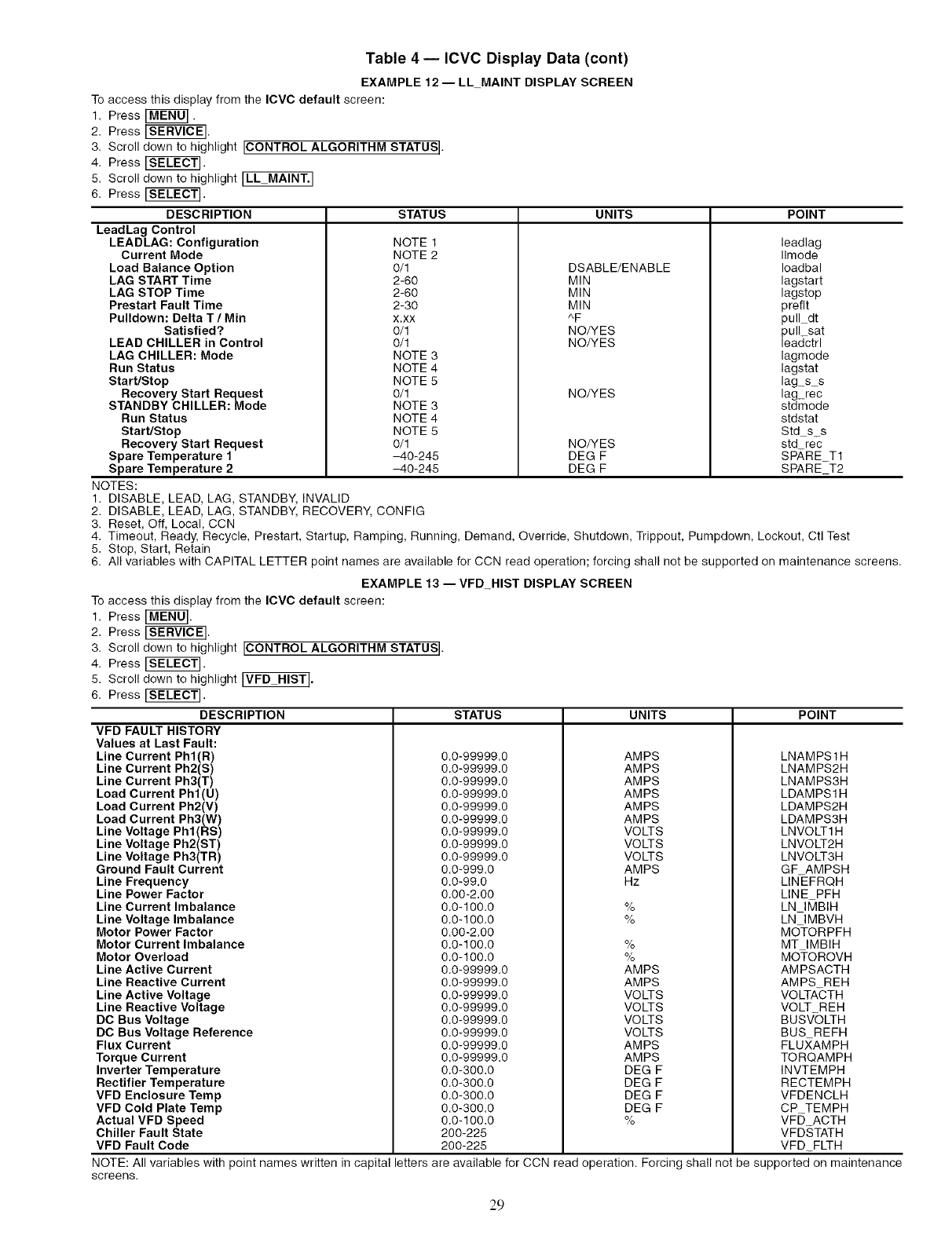
Table 4 -- ICVC Display Data (cont)
EXAMPLE 12- LL_MAINT DISPLAY SCREEN
To access this display from the ICVC default screen:
1. Press _MENO].
2. Press _.
3. Scroll down to highlight [CONTROL ALGORITHM STATUS].
4. Press [SELECT].
5. Scroll down to highlight ILL_MAINT.I
6. Press [S_EC_.
DESCRIPTION STATUS
LeadLag Control
LEADLAG: Configuration NOTE 1
Current Mode NOTE 2
Load Balance Option 0/1
LAG START Time 2-60
LAG STOP Time 2-60
Prestart Fault Time 2-30
Pulldown: Delta T/Min x.xx
Satisfied? 0/1
LEAD CHILLER in Control 0/1
LAG CHILLER: Mode NOTE 3
Run Status NOTE 4
Start/Stop NOTE 5
Recovery Start Request 0/1
STANDBY CHILLER: Mode NOTE 3
Run Status NOTE 4
Start/Stop NOTE 5
Recovery Start Request 0/1
Spare Temperature 1 -40-245
Spare Temperature 2 -40-245
NOTES:
1. DISABLE, LEAD, LAG, STANDBY, INVALID
2. DISABLE, LEAD, LAG, STANDBY, RECOVERY, CONFIG
3. Reset, Off, Local, CCN
UNITS POINT
DSABLE/ENABLE
MIN
MIN
MIN
^F
NO/YES
NO/YES
NO/YES
NO/YES
DEG F
DEG F
leadlag
Ilmode
Ioadbal
lagstart
lagstop
preflt
pull dt
pull_sat
leadctrl
lagmode
lagstat
lag_s_s
lag_rec
stdmode
stdstat
Std s_s
std rec
SP,_RE_T1
SPARE_T2
4. Timeout, Ready, Recycle, Prestart, Startup, Ramping, Running, Demand, Override, Shutdown, Trippout, Pumpdown, Lockout, Ctl Test
5. Stop, Start, Retain
6. All variables with CAPITAL LETTER point names are available for CCN read operation; forcing shall not be supported on maintenance screens.
EXAMPLE 13 -- VFD_HIST DISPLAY SCREEN
To access this display from the ICVC default screen:
1. Press [MEN0].
2. Press _.
3. Scroll down to highlight [CONTROL ALGORITHM STATUS].
4. Press [SELECT].
5. Scroll down to highlight _VFD HIST].
6. Press [_TEC_.
DESCRIPTION
VFD FAULT HISTORY
Values at Last Fault:
Line Current Phl(R)
Line Current Ph2(S)
Line Current Ph3(T)
Load Current Phl(U)
Load Current Ph2(V)
Load Current Ph3(W)
Line Voltage Phl(RS)
Line Voltage Ph2(ST)
Line Voltage Ph3(TR)
Ground Fault Current
Line Frequency
Line Power Factor
Line Current Imbalance
Line Voltage Imbalance
Motor Power Factor
Motor Current Imbalance
Motor Overload
Line Active Current
Line Reactive Current
Line Active Voltage
Line Reactive Voltage
DC Bus Voltage
DC Bus Voltage Reference
Flux Current
Torque Current
Inverter Temperature
Rectifier Temperature
VFD Enclosure Temp
VFD Cold Plate Temp
Actual VFD Speed
Chiller Fault State
VFD Fault Code
STATUS UNITS POINT
0.0-99999.0
0.0-99999.0
0.0-99999.0
0.0-99999.0
0.0-99999.0
0.0-99999.0
0.0-99999.0
0.0-99999.0
0.0-99999.0
0.0-999.0
0.0-99.0
0.00-2.00
0.0-100.0
0.0-100.0
0.00-2.00
0.0-100.0
0.0-100.0
0.0-99999.0
0.0-99999.0
0.0-99999.0
0.0-99999.0
0.0-99999.0
0.0-99999.0
0.0-99999.0
0.0-99999.0
0.0-300.0
0.0-300.0
0.0-300.0
0.0-300.0
0.0-100.0
200-225
200-225
AMPS
AMPS
AMPS
AMPS
AMPS
AMPS
VOLTS
VOLTS
VOLTS
AMPS
Hz
%
%
%
%
AMPS
AMPS
VOLTS
VOLTS
VOLTS
VOLTS
AMPS
AMPS
DEG F
DEG F
DEG F
DEG F
%
LNAMPS1H
LNAMPS2H
LNAMPS3H
LDAMPS1H
LDAMPS2H
LDAMPS3H
LNVOLT1H
LNVOLT2H
LNVOLT3H
GF AMPSH
LIN-EFRQH
LINE PFH
LN_IIV1BIH
LN IMBVH
MO-TORPFH
MT IMBIH
MOTOROVH
AMPSACTH
AMPS REH
VOLTA-CTH
VOLT REH
BUSV-OLTH
BUS REFH
FLU)(AMPH
TORQAMPH
INVTEMPH
RECTEMPH
VFDENCLH
CP TEMPH
VFD ACTH
VFDSTATH
VFD_FLTH
NOTE: All variables with point names written in capital letters are available for CCN read operation. Forcing shall not be supported on maintenance
screens.
29
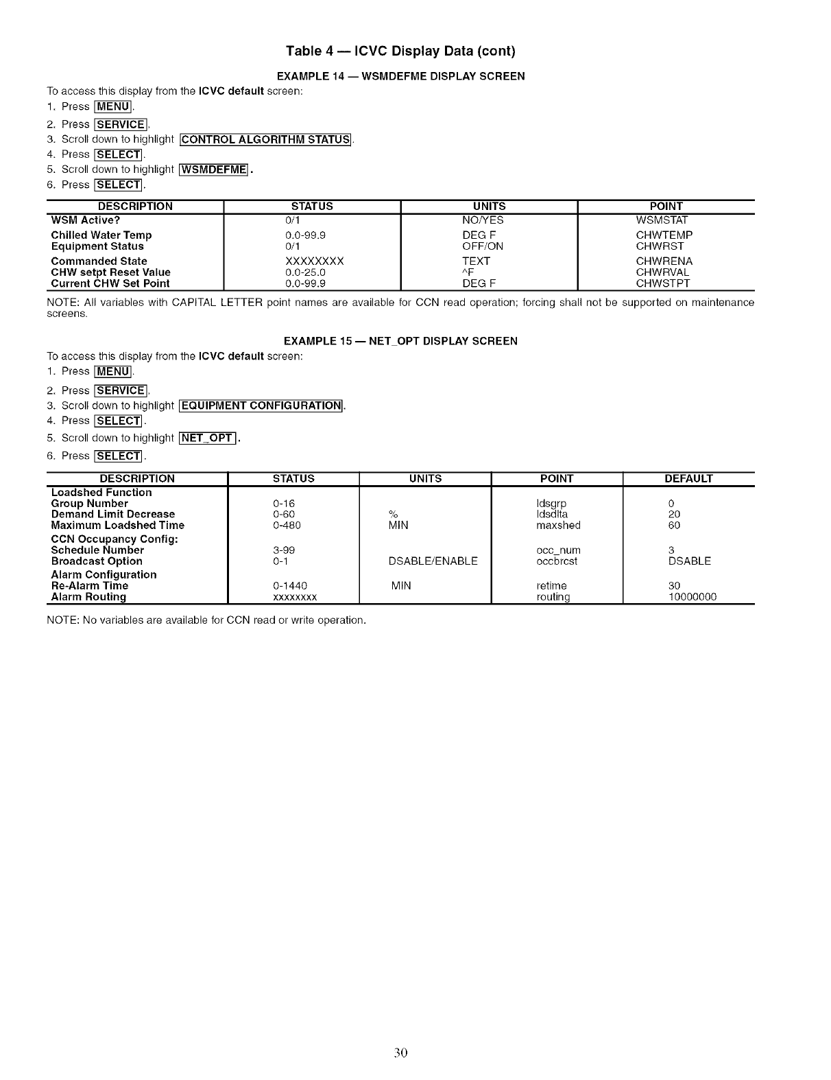
Table 4 -- ICVC Display Data (cont)
EXAMPLE 14 --WSMDEFME DISPLAY SCREEN
To access this display from the ICVC default screen:
1. Press [MENU].
2. Press _.
3. Scroll down to highlight ICONTROL ALGORITHM STATUS I.
4. Press [SELECT].
5. Scroll down to highlight [WSMDEFME].
6. Press [SELECT].
DESCRIPTION STATUS UNITS POINT
WSM Active'?. 0/1 NO/YES WSMSTAT
Chilled Water Temp 0.0-99.9 DEG F CHWTEMP
Equipment Status 0/1 OFF/ON CHWRST
Commanded State XXXXXXXX TEXT CHWRENA
CHW setpt Reset Value 0.0-25.0 ^F CHWRVAL
Current CHW Set Point 0.0-99.9 DEG F CHWSTPT
NOTE: All variables with CAPITAL LETTER point names are available for CCN read operation; forcing shall not be supported on maintenance
screens.
EXAMPLE 15-- NET OPT DISPLAY SCREEN
To access this display from the ICVC default screen:
1. Press [MENU].
2. Press _.
3. Scroll down to highlight [EQUIPMENT CONFIGURATION I.
4. Press [_T].
5. Scroll down to highlight [NET OPT].
6. Press [SE_CT].
DESCRIPTION
Loadshed Function
Group Number
Demand Limit Decrease
Maximum Loadshed Time
CCN Occupancy Config:
Schedule Number
Broadcast Option
Alarm Configuration
Re-Alarm Time
Alarm Routing
STATUS
0-16
0-60
0-480
3-99
0-1
0-1440
xxxxxxxx
UNITS
%
MIN
DSABLE/ENABLE
MIN
POINT
Idsgrp
Idsdlta
maxshed
occ num
occbrcst
retime
routing
DEFAULT
o
2o
6o
3
DSABLE
30
10000000
NOTE: No variables are available for CCN read or write operation.
3O
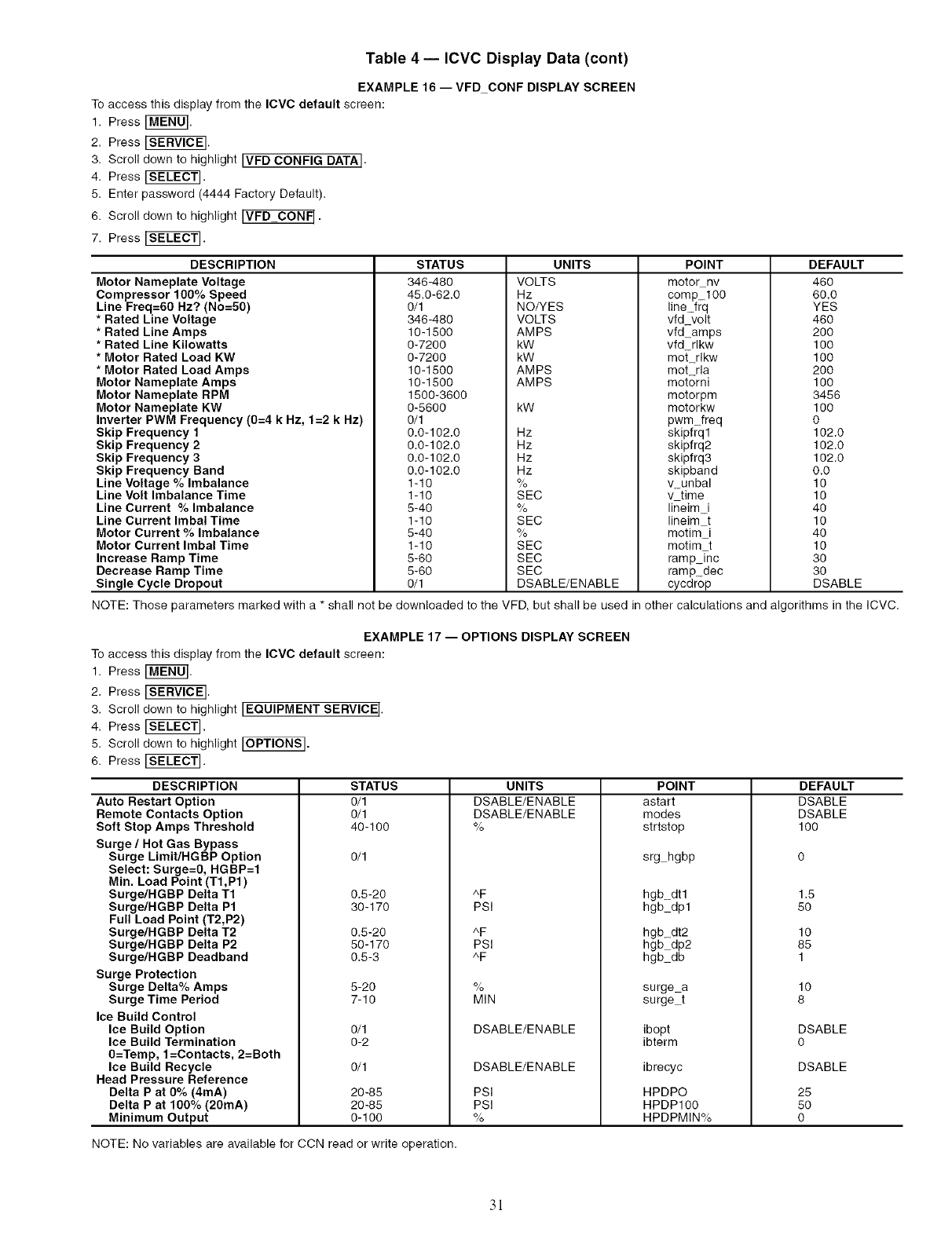
Table 4 -- ICVC Display Data (cont)
EXAMPLE 16- VFD CONF DISPLAY SCREEN
To access this display from the ICVC default screen:
1. Press rMEN0].
2. Press _.
3. Scroll down to highlight [VFD CONFIG DATA[.
4. Press FSELECT1.
5. Enter password (4444 Factory Default).
6. Scroll down to highlight [VFD CONF[.
7. Press [SELECT1.
DESCRIPTION
Motor Nameplate Voltage
Compressor 100% Speed
Line Freq=60 Hz? (No=50)
*Rated Line Voltage
* Rated Line Amps
*Rated Line Kilowatts
*Motor Rated Load KW
*Motor Rated Load Amps
Motor Nameplate Amps
Motor Nameplate RPM
Motor Nameplate KW
Inverter PWM Frequency (0=4 k Hz, 1=2 k Hz)
STATUS
346-480
45.0-62.0
0/1
346-480
10-1500
0-7200
0-7200
10-1500
10-1500
1500-3600
0-5600
O/1
UNITS
VOLTS
Hz
NO/YES
VOLTS
AMPS
kW
kW
AMPS
AMPS
kW
POINT
motornv
comp 100
line frq
vfd volt
vfd amps
vfd rlkw
mot rlkw
mot rla
motorni
motorpm
motorkw
pwm freq
Skip Frequency 1
Skip Frequency 2
Skip Frequency 3
Skip Frequency Band
Line Voltage % Imbalance
Line Volt Imbalance Time
Line Current % Imbalance
Line Current Imbal Time
Motor Current % Imbalance
Motor Current Imbal Time
Increase Ramp Time
Decrease Ramp Time
Single Cycle Dropout
0.0-102.0
0.0-102.0
0.0-102.0
0.0-102.0
1-10
1-10
5-40
1-10
5-40
1-10
5-60
5-60
0/1
Nz
Hz
Hz
Hz
%
SEC
%
SEC
%
SEC
SEC
SEC
DSABLE/ENABLE
skipfrql
skipfrq2
skipfrq3
skipband
v unbal
v time
lineim i
lineim t
motim i
motim t
ramp Tnc
rampdec
cycdrop
DEFAULT
460
60.0
YES
46O
2OO
100
100
2OO
100
3456
100
0
102.0
102.0
102.0
0.0
10
10
4O
10
4O
10
3O
3O
DSABLE
NOTE: Those parameters marked with a * shall not be downloaded to the VFD, but shall be used in other calculations and algorithms in the ICVC.
EXAMPLE 17 -- OPTIONS DISPLAY SCREEN
To access this display from the ICVC default screen:
1. Press [M_U].
2. Press _.
3. Scroll down to highlight IEQUIPMENT SERVICE I.
4. Press [SEL_T].
5. Scroll down to highlight _.
6. Press [_LECT].
DESCRIPTION
Auto Restart Option
Remote Contacts Option
Soft Stop Amps Threshold
Surge/Hot Gas Bypass
Surge Limit/HGBP Option
Select: Surge=0, HGBP=I
Min. Load Point (T1,P1)
Surge/HGBP Delta T1
Surge/HGBP Delta P1
Full Load Point (T2,P2)
Surge/HGBP Delta T2
Surge/HGBP Delta P2
Surge/HGBP Deadband
Surge Protection
Surge Delta% Amps
Surge Time Period
Ice Build Control
Ice Build Option
Ice Build Termination
0=Temp, 1=Contacts, 2=Both
Ice Build Recycle
Head Pressure Reference
Delta P at 0% (4mA)
Delta P at 100% (20mA)
Minimum Output
STATUS
0/1
0/1
40-100
0/1
0.5-20
30-170
0.5-20
50-170
0.5-3
5-20
7-10
0/1
0-2
0/1
20-85
20-85
0-100
UNITS
DSABLE/ENABLE
DSABLE/ENABLE
%
^F
PSI
^F
PSI
^F
%
MIN
DSABLE/ENABLE
DSABLE/ENABLE
PSI
PSI
%
POINT
astart
modes
strtstop
srg hgbp
hgbdtl
hgbdpl
hgbdt2
hgb dp2
hgb db
surge_a
surge t
ibopt
ibterm
ibrecyc
HPDPO
HPDP100
HPDPMIN%
DEFAULT
DSABLE
DSABLE
100
1.5
5O
lO
85
1
lO
8
DSABLE
0
DSABLE
25
5O
0
NOTE: No variables are available for CCN read or write operation.
3!
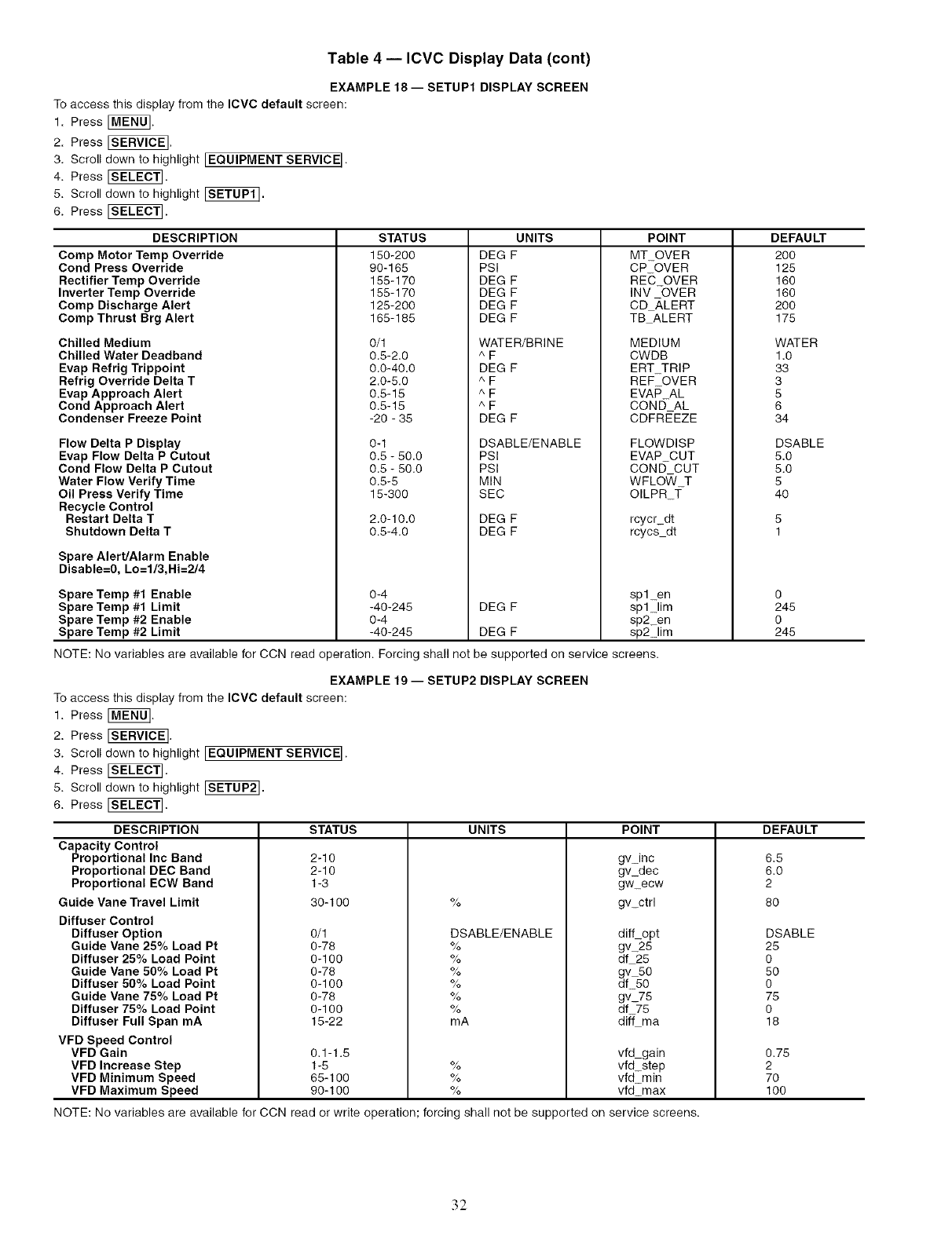
Table 4 -- ICVC Display Data (cont)
EXAMPLE 18 -- SETUP1 DISPLAY SCREEN
To access this display from the ICVC default screen:
1. Press _MENU_.
2. Press _.
3. Scroll down to highlight [EQUIPMENT SERVICE I.
4. Press _SELECTI.
5. Scroll down to highlight ISEf0P1].
6. Press [SE_].
DESCRIPTION
Comp Motor Temp Override
Cond Press Override
Rectifier Temp Override
Inverter Temp Override
Comp Discharge Alert
Comp Thrust Brg Alert
Chilled Medium
Chilled Water Deadband
Evap Refrig Trippoint
Refrig Override Delta T
Evap Approach Alert
Cond Approach Alert
Condenser Freeze Point
Flow Delta P Display
Evap Flow Delta P Cutout
Cond Flow Delta P Cutout
Water Flow Verify Time
Oil Press Verify Time
Recycle Control
Restart Delta T
Shutdown Delta T
Spare Alert/Alarm Enable
Disable=0, Lo=1/3,Hi=2/4
Spare Temp #1 Enable
Spare Temp #1 Limit
Spare Temp #2 Enable
Spare Temp #2 Limit
STATUS
150-200
90-165
155-170
155-170
125-200
165-185
0/1
0.5-2.0
0.0-40.0
2.0-5.0
0.5-15
0.5-15
-20 - 35
0-1
0.5 - 50.0
0.5 - 50.0
0.5-5
UNITS
DEG F
PSI
DEG F
DEG F
DEG F
DEG F
WATER/BRINE
^F
DEG F
^F
^F
^F
DEG F
DSABLE/ENABLE
PSI
PSI
MIN
POINT
MT_OVER
CP OVER
REC OVER
INV -OVER
CD _,LERT
TB ALERT
MEDIUM
CWDB
ERT TRIP
REF OVER
EVAP AL
CONE) AL
CDFRt_EZE
FLOWDISP
EVAP CUT
CONE) CUT
WFLO_/ T
15-300 SEC
2.0-10.0 DEG F
0.5-4.0 DEG F
0-4
-40-245 DEG F
0-4
-40-245 DEG F
OILPR T
rcycr dt
rcycs dt
splen
spllim
sp2_en
sp21im
NOTE: No variables are available for CCN read operation. Forcing shall not be supported on service screens.
EXAMPLE 19 -- SETUP2 DISPLAY SCREEN
To access this display from the ICVC default screen:
1. Press [MENU].
2. Press _.
3. Scroll down to highlight [EQUIPMENT SERVICE].
4. Press _SE[EC_.
5. Scroll down to highlight ISETUP2].
6. Press FSELEC_.
DESCRIPTION
Capacity Control
Proportional Inc Band
Proportional DEC Band
Proportional ECW Band
Guide Vane Travel Limit
Diffuser Control
Diffuser Option
Guide Vane 25% Load Pt
Diffuser 25% Load Point
Guide Vane 50% Load Pt
Diffuser 50% Load Point
Guide Vane 75% Load Pt
Diffuser 75% Load Point
Diffuser Full Span mA
VFD Speed Control
VFD Gain
VFD Increase Step
VFD Minimum Speed
VFD Maximum Speed
DEFAULT
20O
125
160
160
200
175
WATER
1.0
33
3
5
6
34
DSABLE
5.0
5.0
5
4O
0
245
0
245
STATUS UNITS POINT DEFAULT
%
DSABLE/ENABLE
%
%
%
%
%
%
mA
gv_inc
gv_dec
gw_ecw
gv_ctrl
diff_opt
gv25
df 25
gv 50
df 50
gv_75
df 75
diff ma
vfd gain
vfd step
vfd min
vfd_max
2-I0
2-I0
I-3
30- I O0
0/1
0-78
0-100
0-78
0-10o
0-78
0-10o
15-22
0.1-1.5
1-5
65-100
90-100
%
%
%
NOTE: No variables are available for CCN read or write operation; forcing shall not be supported on service screens.
6.5
6.0
2
8O
DSABLE
25
0
5O
0
75
0
18
0.75
2
7O
100
32
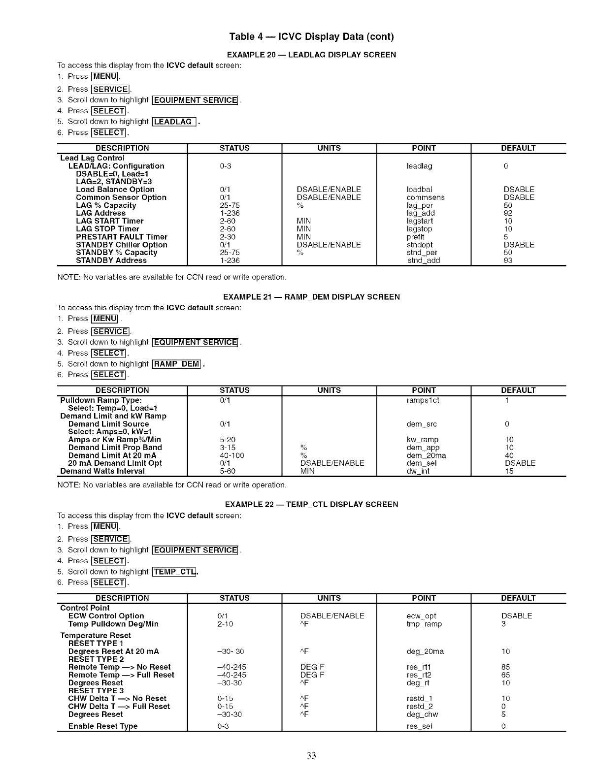
Table 4 -- ICVC Display Data (cont)
EXAMPLE 20 -- LEADLAG DISPLAY SCREEN
To access this display from the ICVC default screen:
1. Press [MENU].
2. Press _.
3. Scroll down to highlight IEQUIPMENT SERVICE I.
4. Press [SELECT].
5. Scroll down to highlight ILEADLAG I.
6. Press [SEL_T].
DESCRIPTION
Lead Lag Control
LEAD/LAG: Configuration
DSABLE=0, Lead=l
LAG=2, STANDBY=3
Load Balance Option
Common Sensor Option
LAG % Capacity
LAG Address
LAG START Timer
LAG STOP Timer
PRESTART FAULT Timer
STANDBY Chiller Option
STANDBY %Capacity
STANDBY Address
STATUS
0-3
0/1
0/1
25-75
1-236
2-60
2-60
2-30
0/1
25-75
1-236
UNITS
DSABLE/ENABLE
DSABLE/ENABLE
%
MIN
MIN
MIN
DSABLE/ENABLE
%
POINT
leadlag
Ioadbal
commsens
lag_per
lagadd
lagstart
lagstop
preflt
stndopt
stnd_per
stnd_add
NOTE: No variables are available for CCN read or write operation.
EXAMPLE 21 -- RAMP DEM DISPLAY SCREEN
To access this display from the IOVC default screen:
1. Press [MENO].
2. Press _.
3. Scroll down to highlight IEQUIPMENT SERVICE I.
4. Press [SELECT].
5. Scroll down to highlight IRAMP DEM I.
6. Press [S_E_].
DESCRIPTION
Pulldown Ramp Type:
Select: Temp=0, Load=l
Demand Limit and kW Ramp
Demand Limit Source
Select: Amps=0, kW=l
Amps or Kw Ramp%/Min
Demand Limit Prop Band
Demand Limit At 20 mA
20 mA Demand Limit Opt
Demand Watts Interval
DEFAULT
o
DSABLE
DSABLE
5O
92
10
10
5
DSABLE
5O
93
STATUS UNITS DEFAULT
0/1 1
%
%
DSABLE/ENABLE
MIN
POINT
rampslct
dem_src
kw ramp
dem_app
dem_20ma
dem sel
dw_i_t
0/1
5-20
3-15
40-100
0/1
5-60
NOTE: No variables are available for CCN read or write operation.
EXAMPLE 221TEMP_CTL DISPLAY SCREEN
To access this display from the ICVC default screen:
1. Press[MEN 0].
2. Press_.
3. Scroll down to highlightlEQUIPMENT SERVICE I.
4. Press[SELECT].
5. Scroll down to highlightlTEMP CTq.
6. Press[SEL_T].
STATUS
0/1
2-10
-30- 30
-40-245
-40-245
-30-30
0-15
0-15
-30-30
UNITS
DSABLE/ENABLE
^F
^F
DEG F
DEG F
^F
AF
AF
AF
POINT
ecw_opt
trap ramp
deg_20ma
res_rtl
res rt2
deg- rt
restd_l
restd 2
deg_chw
res_sel
DESCRIPTION
Control Point
ECW Control Option
Temp Pulldown Deg/Min
Temperature Reset
RESET TYPE f
Degrees Reset At 20 mA
RESET TYPE 2
Remote Temp 1> No Reset
Remote Temp 1> Full Reset
Degrees Reset
RESET TYPE 3
CHW Delta T 1> No Reset
CHW Delta T 1> Full Reset
Degrees Reset
Enable Reset Type 0-3
lO
lO
4o
DSABLE
15
DEFAULT
DSABLE
3
10
85
65
10
10
0
5
0
33
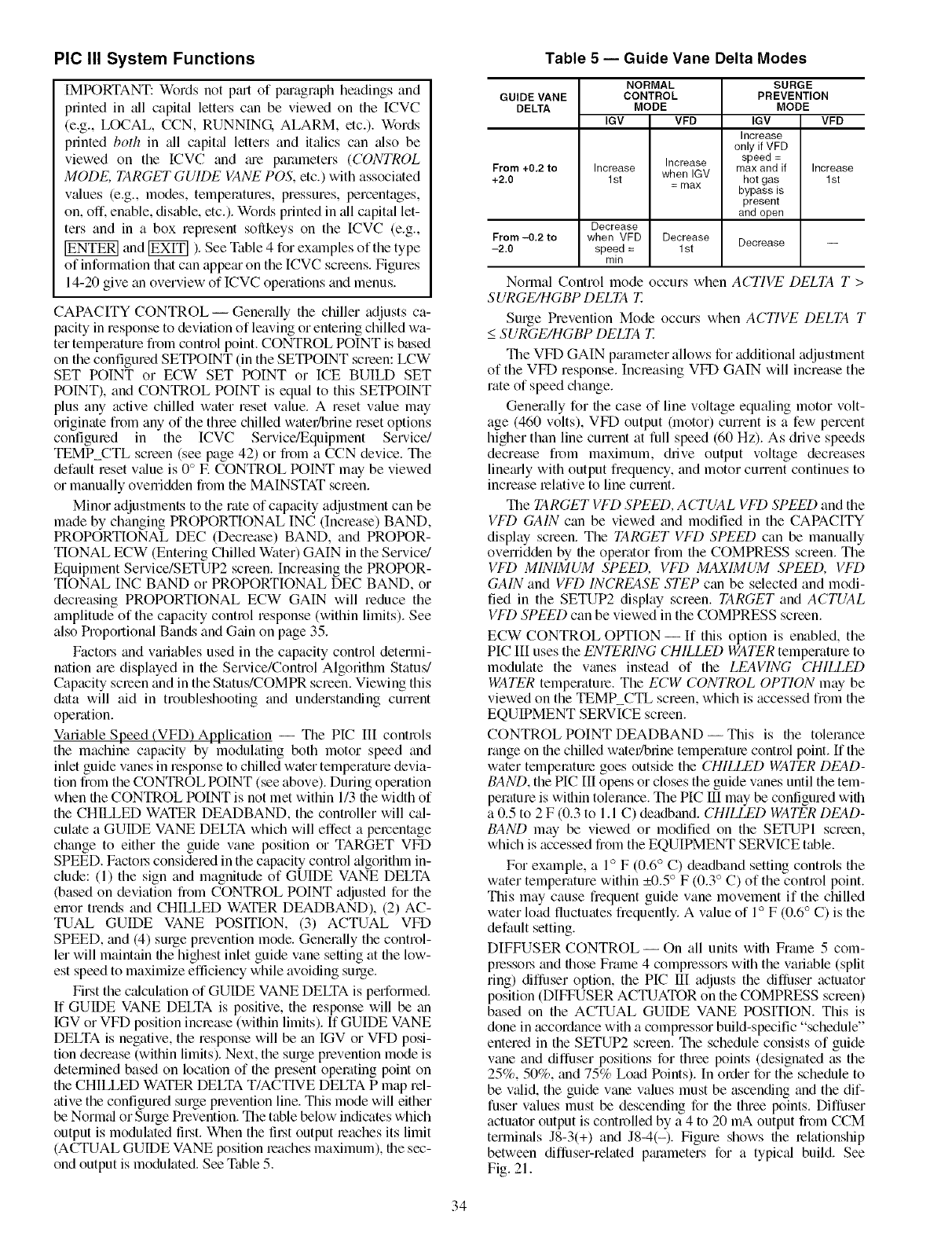
PIC III System Functions
IMPORTANT: Words not Du't of ptu'agraph headings and
printed in all capit_d letters can be viewed on the [CVC
(e.g., LOCAL, CCN, RUNNING ALARM, etc.). Words
printed both in _dl capit_d letters and it_dics can also be
viewed on the ICVC and tu'e parameters (CONTROL
MODE, TARGET GUIDE VANE POS, etc.) with associated
v_dues (e.g., modes, temperatures, pressures, percentages,
on, off. enable, disable, etc.). Words printed in _dlcapital let-
ters and in a box represent sollkeys on the ICVC (e.g.,
and _ ). See Table 4 for exmnples of the type
of information that can appeguon the ICVC screens. Figures
14-20 give an overview of ICVC operations and menus.
CAPACITY CONTROL -- Generally the chiller adjusts ca-
pacity in response to deviation of leaving or entering chilled wa-
ter temperature from control point. CONTROL POINT is based
on the configured SETPOINT (in the SETPOINT screen: LCW
SET POINT or ECW SET POINT or ICE BUILD SET
POINT), and CONTROL POINT is equal to this SETPOINT
plus any active chilled water reset value. A reset v_due may
originate from any of the three chilled water/brine reset options
configured in the ICVC Service/Equipment Service/
TEMP CTL screen (see page 42) or from a CCN device. The
default reset v_due is 0°E CONTROL POINT may be viewed
or manually overridden from the MAINSTAT screen.
Minor adjustments to the rate of capacity adjustment can be
made by changing PROPORTIONAL INC (Increase) BAND,
PROPORTIONAL DEC (Decrease) BAND, and PROPOR-
TIONAL ECW (Entering Chilled Water) GAIN in the Service/
Equipment Service/SETUP2 screen. Increasing the PROPOR-
TIONAL [NC BAND or PROPORTIONAL DEC BAND, or
decreasing PROPORTIONAL ECW GAIN will reduce the
amplitude of the capacity control response (within limits). See
also Proportional Bands and Gain on page 35.
Factors and variables used in the capacity control determi-
nation are displayed in the Service/Control Algorithln Status/
Capacity screen and in the Status/COMPR screen. Viewing this
data will aid in troubleshooting and understanding current
operation.
Variable Speed (VFD) Application -- The PIC III controls
the machine capacity by modulating both motor speed and
inlet guide vanes in response to chilled water temperature devia-
tion from the CONTROL POINT (see above). During operation
when the CONTROL POINT is not met within 1/3 the width of
the CHILLED WATER DEAD)BAND, the controller will cal-
culate a GUIDE VANE DELTA which will effect a percentage
change to either the guide vane position or TARGET VFD
SPEED. Factol.s considered in the capacity control algorithln in-
clude: (1) the sign and magnitude of GUIDE VANE DELTA
(based on deviation from CONTROL POINT adjusted for the
error trends and CHILLED WATER DEAl)BAND), (2) AC-
TUAL GUIDE VANE POSITION, (3) ACTUAL VFD
SPEED, and (4) surge prevention mode. Generally the control-
ler will maintain the highest inlet guide vane setting at the low-
est speed to maximize efficiency while avoiding surge.
First the c',_culation of GUIDE VANE DELTA is performed.
If GUIDE VANE DELTA is positive, the response will be an
IGV or VFD position increase (within limits). If GUIDE VANE
DELTA is negative, the response will be gm IGV or VFD posi-
tion decrease (within limits). Next, the surge prevention mode is
detemfined based on location of the present operating point on
the CHILLED WATER DELTA T/ACTIVE DELTA P map rel-
ative the configured stage prevention line. This mode will either
be Norm_d or Surge Prevention. The table below indicates which
output is modulated that. When the Ih.st output roaches its limit
(ACTUAL GUIDE VANE position roaches maximum), the sec-
ond output is modulated. See Table 5.
Table 5 -- Guide Vane Delta Modes
NORMAL SURGE
GUIDE VANE CONTROL PREVENTION
DELTA MODE MODE
IGV VFD IGV VFD
Increase
only if VFD
speed =
From +0,2 to Increase Increase max and if Increase
+2.0 1st when IGV hot gas 1st
= max bypass is
present
and open
Decrease
From -0.2 to when VFD Decrease Decrease --
-2.0 speed = 1st
rnin
Normal Control mode occurs when ACTIVE DELTA T >
SURGE/HGBP DELTA T_
Surge Prevention Mode occurs when ACTIVE DELTA T
<SURGE/HGBP DELTA T_
The VFD GAIN ptuameter allows for additional adjustment
of the VFD response. Increasing VFD GAIN will increase the
rate of speed change.
Generally for the case of line voltage equaling motor volt-
age (460 volts), VFD output 0notor) current is a few percent
higher than line current at full speed (60 Hz). As drive speeds
decrease fiom maximum, drive output voltage decreases
linedy with output frequency, and motor current continues to
increase relative to line current.
The TARGET VFD SPEED, ACTUAL VFD SPEED and the
VFD GAIN can be viewed and modified in the CAPACITY
display screen. The TARGET VFD SPEED can be manually
overridden by the operator fi'om the COMPRESS screen. The
VFD MINIMUM SPEED, VFD MAXIMUM SPEED, VFD
GAIN and VFD INCREASE STEP can be selected and modi-
fied in the SETUP2 display screen. TARGET and ACTUAL
VFD SPEED can be viewed in the COMPRESS screen.
ECW CONTROL OPTION -- If this option is enabled, the
PIC III uses the ENTERING CHILLED WATER temperature to
modulate the vanes instead of the LEAVING CHILLED
WATER temperature. The ECW CONTROL OPTION may be
viewed on the TEMP_CTL screen, which is accessed fiom the
EQUIPMENT SERVICE screen.
CONTROL POINT DEAD)BAND-- This is the tolerance
range on the chilled water/brine temperature control point. If the
water temperature goes outside the CHILLED WATER DEAD-
BAND, the PIC III opens or closes the guide vanes until the tem-
perature is within tolerance. The PIC III may be configured with
a 0.5 to 2 F (0.3 to 1.1 C) deadband. CHILLED WATER DEAD-
BAND may be viewed or modified on the SETUPI screen,
which is accessed from the EQUIPMENT SERVICE table.
For example, a 1° F (0.6 ° C) deadband setting controls the
water temperature within _+0.5° F (0.3 ° C) of the control point.
This may cause fiequent guide vane movement if the chilled
water load fluctuates frequently. A value of 1° F (0.6° C) is the
default setting.
DIFFUSER CONTROL--On all units with Frmne 5 com-
pmssol.s and those Frmne 4 compressors with the variable (split
ring) dilluser option, the PIC III adjusts the difluser actuator
position (DIFFUSER ACTUATOR on the COMPRESS screen)
based on the ACTUAL GUIDE VANE POSITION. This is
done in accordance with a compressor build-specific "schedule"
entered in the SETUP2 screen. The schedule consists of guide
wme and diffuser positions for three points (designated as the
25%, 50%, and 75% Load Points). In order for the schedule to
be valid, the guide vane values must be ascending and the dif-
fuser values must be descending for the three points. Diflhser
actuator output is controlled by a 4 to 20 mA output from CCM
terminals J8-3(+) and J8-4(-). Figure shows the relationship
between diffuser-related pguameters for a typic_d build. See
Fig. 21.
34
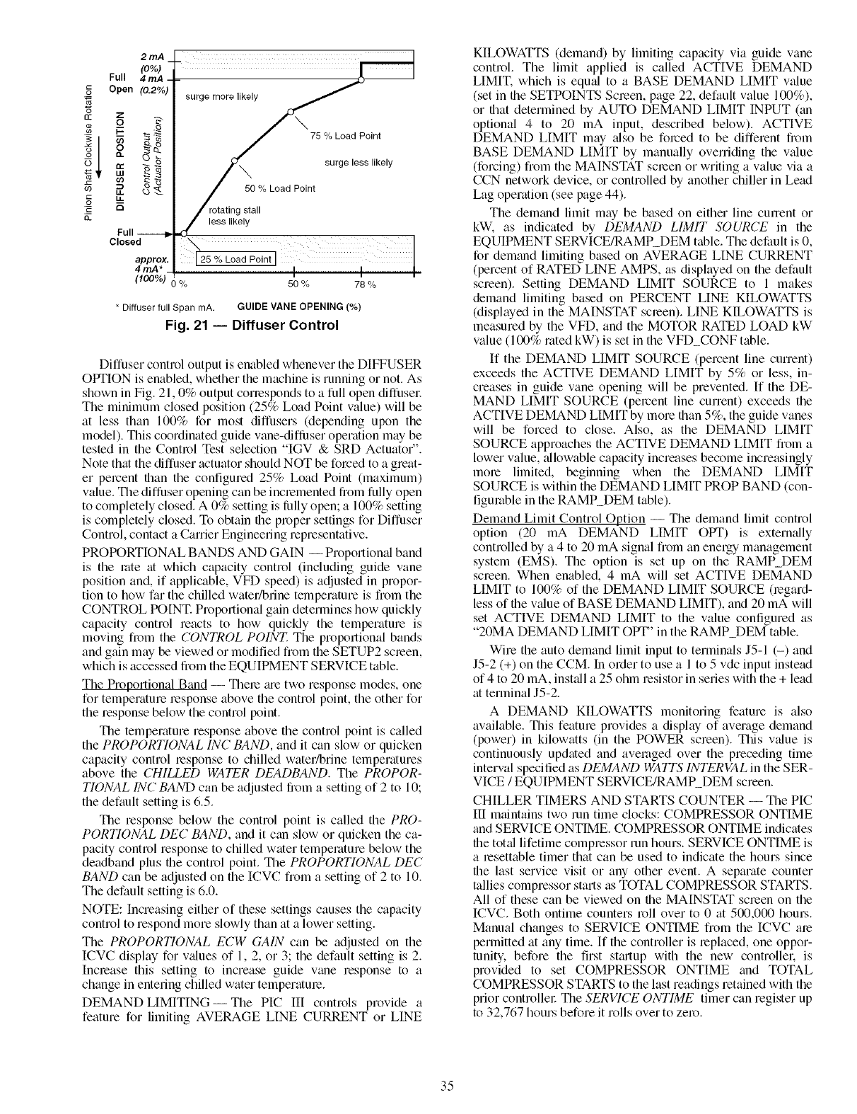
*6
c£
o
o
09
rJ.
2mA
(O%)
Full 4 mA
Open (0.2%
Full --
Closed
approx,
4rnA*
(_00%) 0 %
surge more likely
75 % Load Point
surge less likely
50 % Load Point
rotating stall
less likely
25 % Load Point
I
50 % 78 %
* Diffuser full Span mA. GUIDE VANE OPENING (%)
Fig. 21 -- Diffuser Control
Diffuser control output is enabled whenever the DIFFUSER
OPTION is enabled, whether the machine is rtmning or not. As
shown in Fig. 21,0% output corresponds to a full open diffusel:
The minimum closed position (25% Load Point value) will be
at less than 100% for most diffusers (depending upon the
model). This coordinated guide vane-diffiJser operation may be
tested in the Control Test selection "IGV & SRD Actuator".
Note that the diffuser actuator should NOT be forced to a great-
er percent than the configured 25% Load Point (maximum)
value. The diffuser opening can be incremented from fully open
to completely closed. A 0% setting is tully open; a 100% setting
is completely closed. To obtain file proper settings for Diffuser
Control, contact a Carrier Engineering representative.
PROPORTIONAL BANDS AND GAIN -- Proportiomfl band
is the rote at which capacity control (including guide vane
position and, if applicable, VFD speed) is adjusted in propor-
tion to how far the chilled water/brine temperature is from the
CONTROL POINT. Proportional gain determines how quickly
capacity control reacts to how quickly the temperature is
moving from the CONTROL POINT. The proportional bands
and gain may be viewed or modified from the SETUP2 scleen,
which is accessed from the EQUIPMENT SERVICE table.
The Proportional Band -- Thele gu'e two response modes, one
for temperature response above the control point, the other for
the response below the control point.
The temperature response above the control point is called
the PROPORTIONAL INC BAND, and it can slow or quicken
capacity control response to chilled water/brine temperatures
above the CHILLED WATER DEADBAND. The PROPOR-
TIONAL INCBAND can be adjusted from a setting of 2 to 10;
the default setting is 6.5.
The response below the control point is called the PRO-
PORTIONAL DEC BAND, and it can slow or quicken the ca-
pacity control response to chilled water temperature below the
deadband plus file control point. The PROPORTIONAL DEC
BAND can be adjusted on the ICVC from a setting of 2 to 10.
The default setting is 6.0.
NOTE: Increasing either of these settings causes the capacity
control to respond more slowly than at a lower setting.
The PROPORTIONAL ECW GAIN can be adjusted on the
ICVC display for v_dues of 1, 2, or 3; the default setting is 2.
Increase this setting to increase guide vane response to a
change in entering chilled water temperatme.
DEMAND LIMITING--The PIC III controls provide a
feature for limiting AVERAGE LINE CURRENT or LINE
KILOWATTS (demand) by limiting capacity via guide vane
control. The limit applied is called ACTIVE DEMAND
LIMIT. which is equ_d to a BASE DEMAND LIMIT value
(set in the SETPOINTS Screen, page 22, default value 100%),
or that determined by AUTO DEMAND LIMIT INPUT (tin
optional 4 to 20 mA input, described below). ACTIVE
DEMAND LIMIT may _flso be forced to be different from
BASE DEMAND LIMIT by manually overriding the value
(forcing) from the MAINSTAT screen or writing a value via a
CCN network device, or controlled by another chiller in Lead
Lag operation (see page 44).
The demand limit may be based on either line cunent or
kW. as indicated by DEMAND LIMIT SOURCE in the
EQUIPMENT SERVICE/RAMP_DEM table. The default is 0,
for demand limiting based on AVERAGE LINE CURRENT
(percent of RATED LINE AMPS, as displayed on the default
screen). Setting DEMAND LIMIT SOURCE to 1 makes
demand limiting based on PERCENT LINE KILOWATTS
(displayed in the MAINSTAT scleen). LINE KILOWATTS is
measured by the VFD, and the MOTOR RATED LOAD kW
value (100% rated kW) is set in the VFD_CONF table.
If the DEMAND LIMIT SOURCE (percent line current)
exceeds the ACTIVE DEMAND LIMIT by 5% or less, in-
creases in guide vane opening will be prevented. If the DE-
MAND LIMIT SOURCE (percent line current) exceeds the
ACTIVE DEMAND LIMIT by more than 5%, the guide vanes
will be forced to close. Also, as the DEMAND LIMIT
SOURCE approaches the ACTIVE DEMAND LIMIT from a
lower value, allowable capacity increases become increasingly
more limited, beginning when the DEMAND LIMIT
SOURCE is within the DEMAND LIMIT PROP BAND (con-
figumble in the RAMP_DEM table).
Demand Limit Control Option -- The demand limit control
option (20 mA DEMAND LIMIT OPT) is extern_flly
controlled by a 4 to 20 mA signal from an energy management
system (EMS). The option is set up on the RAMP_DEM
screen. When enabled, 4 mA will set ACTIVE DEMAND
LIMIT to 100% of the DEMAND LIMIT SOURCE Qegard-
less of the value of BASE DEMAND LIMIT), and 20 mA will
set ACTIVE DEMAND LIMIT to the value configured as
"20MA DEMAND LIMIT OPT" in the RAMP_DEM table.
Wire the auto demand limit input to terminals J5-1 (-) and
J5-2 (+) on the CCM. In order to use a 1 to 5 vdc input instead
of 4 to 20 mA, install a 25 ohm resistor in series with the + lead
at terminal J5-2.
A DEMAND KILOWATI'S monitoring feature is also
available. This feature provides a display of average demand
(power) in kilowatts (in the POWER screen). This v_due is
continuously updated and averaged over the preceding time
interval specified as DEMAND WATFS INTERVAL in the SER-
VICE /EQUIPMENT SERVICE/RAMP DEM screen.
CHILLER TIMERS AND STARTS COUNTER -- The PIC
III m_dntains two run time clocks: COMPRESSOR ONTIME
and SERVICE ONTIME. COMPRESSOR ONTIME indicates
file total lifetime compressor run hours. SERVICE ONTIME is
a _esettable timer that can be used to indicate the hours since
file last service visit or any other event. A separate counter
tallies compressor stmls as TOTAL COMPRESSOR STARTS.
All of these can be viewed on the MA[NSTAT screen on the
ICVC. Both ontime counters roll over to 0 at 500,000 hom.s.
Manual changes to SERVICE ONTIME from the ICVC me
permitted at any time. If the controller is replaced, one oppor-
tunity, before the first st_utup with the new controllel; is
provided to set COMPRESSOR ONTIME and TOTAL
COMPRESSOR STARTS to the last readings retained with the
prior controllel: The SERVICE ONTIME timer can register up
to 32,767 hours before it rolls over to zero.
35
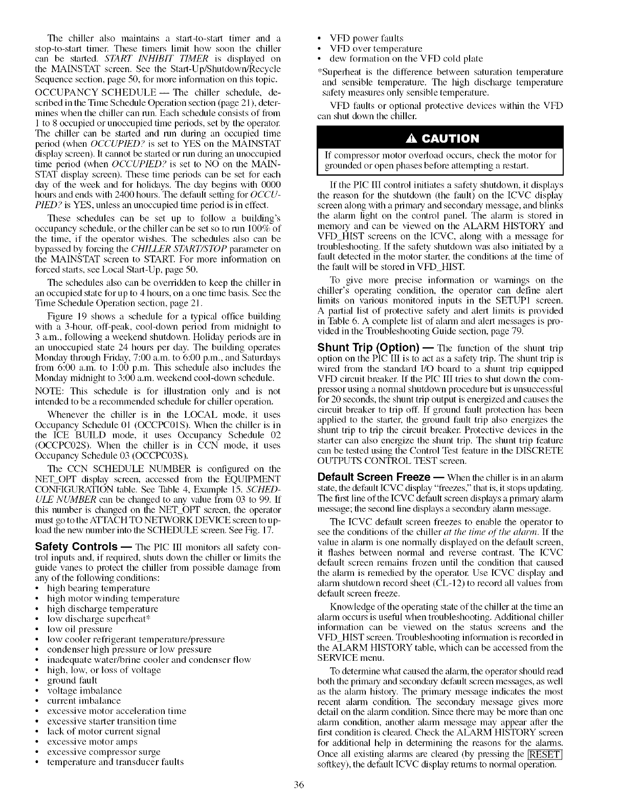
Thechilleralsomaintainsa start-to-stmttimer and a
stop-to-start time_: These timers limit how soon the chiller
can be started. START INHIBIT TIMER is displayed on
the MAINSTAT screen. See the Start-Up/Shutdown/Recycle
Sequence section, page 50, for more information on this topic.
OCCUPANCY SCHEDULE--The chiller schedule, de-
scribed in the Time Schedule Operation section (page 21 ), deter-
mines when the chiller can ran. Each schedule consists of from
1 to 8 occupied or unoccupied time periods, set by the operatol:
The chiller can be stm-ted and run during an occupied time
period (when OCCUPIED? is set to YES on the MAINSTAT
display screen). It cannot be started or run during an unoccupied
time period (when OCCUPIED? is set to NO on file MAIN-
STAT display screen). These time periods can be set for each
&ty of file week and for holi&tys. The day begins wifll 0000
hours and ends with 2400 hours. The default setting for OCCU-
PIED? is YES, unless an unoccupied time period is in effect.
These schedules can be set up to follow a building's
occupancy schedule, or the chiller can be set so to run 100% of
the time, if the operator wishes. The schedules also can be
bypassed by forcing the CHILLER START/STOP parameter on
the MAINSTAT screen to START. For more information on
forced starts, see Loc_fl Start-Up, page 50.
The schedules also can be overridden to keep file chiller in
an occupied state for up to 4 hours, on a one time basis. See the
Time Schedule Operation section, page 21.
Figure 19 shows a schedule for a typical office building
with a 3-horn: off-peak, cool-down period from midnight to
3 a.m., following a weekend shutdown. Holickly periods are in
an unoccupied state 24 hours per day. The building operates
Monday through Friday. 7:00 a.m. to 6:00 p.m., and Saturdays
from 6:00 a.m. to 1:00 p.m. This schedule also includes the
Monday midnight to 3:00 a.m. weekend cool-down schedule.
NOTE: This schedule is for illustration only and is not
intended to be a recommended schedule for chiller operation.
Whenever the chiller is in the LOCAL mode, it uses
Occupancy Schedule 01 (OCCPC01S). When the chiller is in
the ICE BUILD mode, it uses Occupancy Schedule 02
(OCCPC02S). When the chiller is in CCN mode, it uses
Occupancy Schedule 03 (OCCPC03S).
The CCN SCHEDULE NUMBER is configured on the
NET OPT display scleen, accessed from the EQUIPMENT
CONFIGURATION table. See NiNe 4, Exalnple 15. SCHED-
ULE NUMBER can be changed to tiny v_flue from 03 to 99. If
this number is changed on the NET OPT screen, the operator
must go to the ATTACH TO NETWORK DEVICE screen to up-
load the new number into the SCHEDULE screen. See Fig. 17.
Safety Controls -- _n_e PIC III monitors all safety con-
trol inputs and, if required, shuts down the chiller or limits the
guide wines to protect the chiller from possible damage from
any of the following conditions:
• high bearing temperature
• high motor winding temperature
• high discharge temperature
• low discharge superlleat*
• low oil pressure
• low cooler refrigerant temperature/pressure
• condenser high pressure or low pressure
• inadequate water/brine cooler and condenser flow
• high, low, or loss of voltage
• ground fault
• voltage imbalance
• current imbalance
• excessive motor acceleration time
• excessive starter transition time
• lack of motor current signal
• excessive motor amps
• excessive compressor surge
• temperature and transducer faults
• VFD power faults
• VFD over temperature
• dew formation on the VFD cold plate
*Superlleat is the difference between saturation temperature
and sensible temperature. The high discharge temperature
safety measures only sensible temperature.
VFD faults or optional protective devices within the VFD
can shut down the chillel:
If compressor motor overload occurs, check the motor for
grounded or open phases before attempting a restart.
If the PIC [IXcontrol initiates a safety shutdown, it displays
the reason for the shutdown (the fault) on the ICVC display
screen along with a primmy and seconda qmessage, and blinks
the alarm light on the control panel. The ahum is stored in
memory and can be viewed on the ALARM HISTORY and
VFD_HIST screens on the ICVC, along with a message for
troubleshooting. If the safety shutdown was also initiated by a
fault detected in the motor stm-tek the conditions at the time of
the fault will be stored in VFD_HIST.
To give morn precise information or warnings on the
chiller's operating condition, the operator can define alert
limits on various monitored inputs in the SETUPI screen.
A partkd list of protective safety and alert limits is provided
in Table 6. A complete list of alarm and alert messages is pro-
vided in the Troubleshooting Guide section, page 79.
Shunt Trip (Option) -- The function of the shunt trip
option on the PIC Ill is to act as a safety trip. The shunt trip is
wired from the stan&trd I/O board to a shunt trip equipped
VFD circuit breakel: If the HC IIl tries to shut down the com-
pressor using a normal shutdown procedure but is unsuccessful
for 20 seconds, the shunt trip output is energized and causes the
circuit breaker to trip off. If ground fault protection has been
applied to the startel; file ground fault trip also energizes the
shunt trip to trip the circuit breakel: Protective devices in the
starter can also energize the shunt trip. The shunt trip feature
can be tested using the Control Test feature in the DISCRETE
OUTPUTS CONTROL TEST screen.
Default Screen Freeze -- When the chiller is in an al;um
state, the default ICVC display "freezes," that is, it stops updating.
The til_t line of the ICVC default screen displays a primary akum
message; the second line displays a secon&lry ;darm message.
The ICVC default screen freezes to enable the operator to
see the conditions of the chiller at the time of the alarm. If the
value in almm is one nommlly displayed on the default screen,
it flashes between normal and reverse contrast. The ICVC
default screen remains frozen until the condition that caused
the akum is remedied by the operator Use [CVC display and
alarm shutdown record sheet (CL-12) to record all v;dues from
default screen freeze.
Knowledge of the operating state of the chiller at file time an
alarm occurs is useful when troubleshooting. Additional chiller
information can be viewed on the status screens and the
VFD_HIST screen. Troubleshooting information is recorded in
the ALARM HISTORY table, which can be accessed from the
SERVICE menu.
To determine what caused the _flmm, the operator should mad
both file primary and secondm-y default screen messages, as well
as the aimin history. The primmy message indicates file most
recent almm condition. The secon&lry message gives more
derail on the algum condition. Since there may be more than one
alarm condition, another _darm message may appetu after the
fil.st condition is clemed. Check the ALARM HISTORY screen
for additional help in determining the reasons for file _flarms.
Once _dl existing _dmms me clemed (by pressing the
softkey), the default ICVC display returns to norm_fl operation.
36
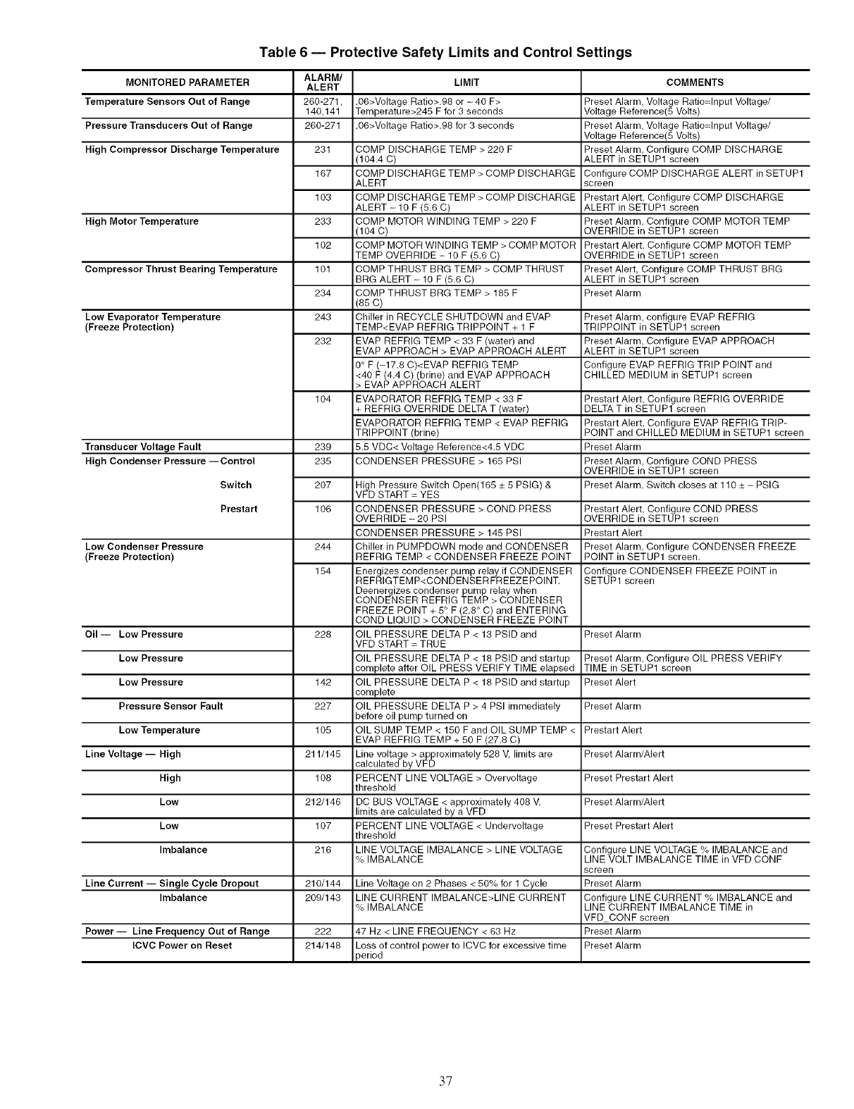
Table 6 -- Protective Safety Limits and Control Settings
MONITORED PARAMETER LIMIT COMMENTS
Temperature Sensors Out of Range .O6>Voltage Ratio>.98 or - 40 F>
Temperature>245 F for 3 seconds
Pressure Transducers Out of Range .06>Voltage Ratio>.98 for 3 seconds
High Compressor Discharge Temperature
High Motor Temperature
Compressor Thrust Bearing Temperature
Low Evaporator Temperature
Freeze Protection)
Transducer Voltage Fault
High Condenser Pressure --Control
Switch
Prestart
Low Condenser Pressure
Freeze Protection)
Oil-- Low Pressure
Low Pressure
Low Pressure
Pressure Sensor Fault
Low Temperature
Line Voltage--High
High
Low
Low
Imbalance
Line Current -- Single Cycle Dropout
Imbalance
Power -- Line Frequency Out of Range
ICVC Power on Reset
ALARM/
ALERT
260-271,
140,141
260-271
231
167
103
233
102
101
234
243
232
1o4
239
235
207
106
244
154
228
142
227
105
211/145
108
212/146
107
216
210/144
209/143
222
214/148
COMP DISCHARGE TEMP > 220 F
(104.4 C)
COMP DISCHARGE TEMP > COMP DISCHARGE
ALERT
COMP DISCHARGE TEMP > COMP DISCHARGE
ALERT - 10 F (5.6 C)
COMP MOTOR WINDING TEMP > 220 F
(104 C)
COMP MOTOR WINDING TEMP > COMP MOTOR
TEMP OVERRIDE - 10 F (5.6 C)
COMP THRUST BRG TEMP > COMP THRUST
BRG ALERT - 10 F (5.6 C)
COMP THRUST BRG TEMP > 185 F
(85 C)
Chiller in RECYCLE SHUTDOWN and EVAP
TEMP<EVAP REFRIG TRIPPOINT + 1 F
EVAP REFRIG TEMP < 33 F (water) and
EVAP APPROACH > EVAP APPROACH ALERT
0° F (-17.8 C)<EVAP REFRIG TEMP
<40 F (4.4 C) (brine) and EVAP APPROACH
> EVAP APPROACH ALERT
EVAPORATOR REFRIG TEMP < 33 F
+ REFRIG OVERRIDE DELTA T (water)
EVAPORATOR REFRIG TEMP < EVAP REFRIG
TRIPPOINT (brine)
5.5 VDC< Voltage Reference<4.5 VDC
CONDENSER PRESSURE > 165 PSI
High Pressure Switch Open(165 _+5 PSIG) &
VFD START = YES
CONDENSER PRESSURE > COND PRESS
OVERRIDE - 20 PSI
CONDENSER PRESSURE > 145 PSI
Chiller in PUMPDOWN mode and CONDENSER
REFRIG TEMP < CONDENSER FREEZE POINT
Energizes condenser pump relay if CONDENSER
REFRIGTEMP<CONDENSER FREEZEPOINT.
Deenergizes condenser pump relay when
CONDENSER REFRIG TEMP > CONDENSER
FREEZE POINT + 5° F (2.8 ° C) and ENTERING
COND LIQUID > CONDENSER FREEZE POINT
OIL PRESSURE DELTA P < 13 PSlD and
VFD START = TRUE
OIL PRESSURE DELTA P < 18 PSlD and startup
complete after OIL PRESS VERIFY TIME elapsed
OIL PRESSURE DELTA P < 18 PSlD and startup
complete
OIL PRESSURE DELTA P > 4 PSI immediately
before oil pump turned on
OILSUMPTEMP < 150 Fand OILSUMPTEMP <
EVAP REFRIG TEMP + 50 F (27.8 C)
Line voltage > approximately 528 V, limits are
calculated by VFD
PERCENT LINE VOLTAGE > Overveltage
threshold
DC BUS VOLTAGE < approximately 408 V,
limits are calculated by a VFD
PERCENT LINE VOLTAGE < Undervoltage
threshold
LINE VOLTAGE IMBALANCE > LINE VOLTAGE
% IMBALANCE
Line Voltage on 2 Phases < 50% for 1 Cycle
LINE CURRENT IMBALANCE>LINE CURRENT
% IMBALANCE
47 Hz < LINE FREQUENCY < 63 Hz
Loss of control power to ICVC for excessive time
_eriod
Preset Alarm, Voltage Ratio=Input Voltage/
Voltage Reference(5 Volts)
Preset Alarm, Voltage Ratio=Input Voltage/
Voltage Reference(5 Volts)
Preset Alarm, Configure COMP DISCHARGE
ALERT in SETUP1 screen
Configure COMP DISCHARGE ALERT in SETUP1
screen
Prestart Alert, Configure COMP DISCHARGE
ALERT in SETUP1 screen
Preset Alarm, Configure COMP MOTOR TEMP
OVERRIDE in SETUP1 screen
Prestart Alert, Configure COMP MOTOR TEMP
OVERRIDE in SETUP1 screen
Preset Alert, Configure COMP THRUST BRG
ALERT in SETUP1 screen
Preset Alarm
Preset Alarm, configure EVAP REFRIG
TRIPPOINT in SETUP1 screen
Preset Alarm, Configure EVAP APPROACH
ALERT in SETUP1 screen
Configure EVAP REFRIG TRIP POINT and
CHILLED MEDIUM in SETUP1 screen
Prestart Alert, Configure REFRIG OVERRIDE
DELTA T in SETUP1 screen
Prestart Alert, Configure EVAP REFRIG TRIP-
POINT and CHILLED MEDIUM in SETUP1 screen
Preset Alarm
Preset Alarm, Configure COND PRESS
OVERRIDE in SETUP1 screen
Preset Alarm, Switch closes at 110 _+- PSIG
Prestart Alert, Configure COND PRESS
OVERRIDE in SETUP1 screen
Prestart Alert
Preset Alarm, Configure CONDENSER FREEZE
POINT in SETUP1 screen.
Configure CONDENSER FREEZE POINT in
SETUP1 screen
Preset Alarm
Preset Alarm, Configure OIL PRESS VERIFY
TIME in SETUP1 screen
Preset Alert
Preset Alarm
Prestart Alert
Preset Alarm/Alert
Preset Prestart Alert
Preset Alarm/Alert
Preset Prestart Alert
Configure LINE VOLTAGE % IMBALANCE and
LINE VOLT IMBALANCE TIME in VFD CONF
screen
Preset Alarm
Configure LINE CURRENT % IMBALANCE and
LINE CURRENT IMBALANCE TIME in
VFD CONF screen
Preset Alarm
Preset Alarm
37
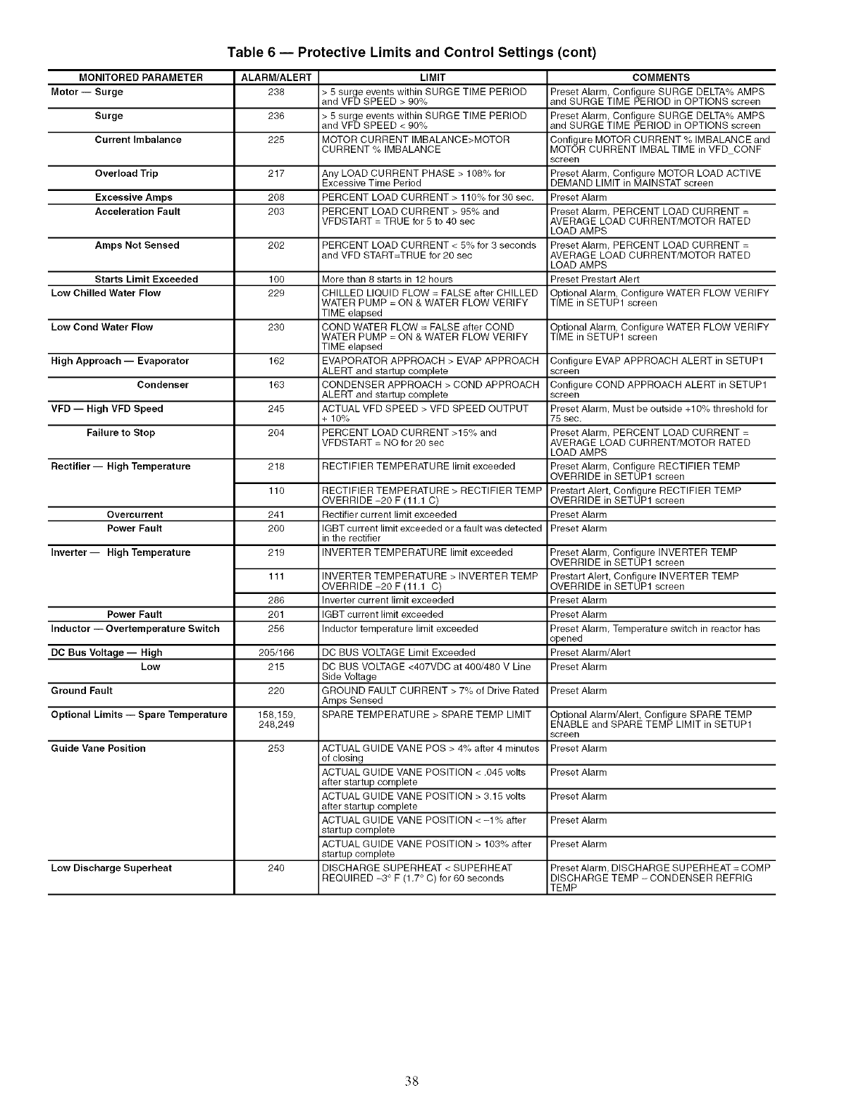
Table 6 -- Protective Limits and Control Settings (cont)
MONITORED PARAMETER
Motor- Surge
Surge
Current Imbalance
Overload Trip
Excessive Amps
Acceleration Fault
Amps Not Sensed
Starts Limit Exceeded
Low Chilled Water Flow
Low Cond Water Flow
High Approach--Evaporator
Condenser
VFD--High VFD Speed
Failureto Stop
Rectifier-- High Temperature
Overcurrent
Power Fault
Inverter-- High Temperature
Power Fault
Inductor -- Overtemperature Switch
DC Bus Voltage -- High
Low
Ground Fault
Optional Limits -- Spare Temperature
Guide Vane Position
Low Discharge Superheat
ALARM/ALERT
236
236
225
217
206
2O3
202
100
229
230
162
163
245
204
218
110
241
2OO
219
111
286
201
256
205/166
215
22O
158,159,
248,249
253
240
LIMIT
> 5 surge events within SURGE TIME PERIOD
and VFD SPEED > 90%
> 5 surge events within SURGE TIME PERIOD
and VFD SPEED < 90%
MOTOR CURRENT IMBALANCE>MOTOR
CURRENT % IMBALANCE
Any LOAD CURRENT PHASE > 108% for
Excessive Time Period
PERCENT LOAD CURRENT > 110% for 30 sec.
PERCENT LOAD CURRENT > 95% and
VFDSTART = TRUE for 5 to 40 sec
PERCENT LOAD CURRENT < 5% for 3 seconds
and VFD START=TRUE for 20 sec
More than 8 starts in 12 hours
CHILLED LIQUID FLOW = FALSE after CHILLED
WATER PUMP = ON & WATER FLOW VERIFY
TIME elapsed
COND WATER FLOW = FALSE after COND
WATER PUMP = ON & WATER FLOW VERIFY
TIME elapsed
EVAPORATOR APPROACH > EVAP APPROACH
ALERT and startup complete
CONDENSER APPROACH > COND APPROACH
ALERT and startup complete
ACTUAL VFD SPEED > VFD SPEED OUTPUT
+ 10%
PERCENT LOAD CURRENT >15% and
VFDSTART = NO for 20 sec
RECTIFIER TEMPERATURE limit exceeded
RECTIFIER TEMPERATURE > RECTIFIER TEMP
OVERRIDE -20 F (11.1 C)
Rectifier current limit exceeded
IGBT current limit exceeded or a fault was detected
in the rectifier
INVERTER TEMPERATURE limit exceeded
INVERTER TEMPERATURE > INVERTER TEMP
OVERRIDE-20 F (11.1 C)
Inverter current limit exceeded
IGBT current limit exceeded
Inductor temperature limit exceeded
DC BUS VOLTAGE Limit Exceeded
DC BUS VOLTAGE <407VDC at 400/480 V Line
Side Voltage
GROUND FAULT CURRENT > 7% of Drive Rated
Amps Sensed
SPARE TEMPERATURE > SPARE TEMP LIMIT
ACTUAL GUIDE VANE POS > 4% after 4 minutes
of closing
ACTUAL GUIDE VANE POSITION < .045 volts
after startup complete
ACTUAL GUIDE VANE POSITION > 3.15 volts
after startup complete
ACTUAL GUIDE VANE POSITION < -1% after
startup complete
ACTUAL GUIDE VANE POSITION > 103% after
startup complete
DISCHARGE SUPERHEAT < SUPERHEAT
REQUIRED -3 ° F (1.7 ° C) for 60 seconds
COMMENTS
Preset Alarm, Configure SURGE DELTA% AMPS
and SURGE TIME PERIOD in OPTIONS screen
Preset Alarm, Configure SURGE DELTA% AMPS
and SURGE TIME PERIOD in OPTIONS screen
Configure MOTOR CURRENT % IMBALANCE and
MOTOR CURRENT IMBAL TIME in VFD CONF
screen
Preset Alarm, Configure MOTOR LOAD ACTIVE
DEMAND LIMIT in MAINSTAT screen
Preset Alarm
Preset Alarm, PERCENT LOAD CURRENT =
AVERAGE LOAD CURRENT/MOTOR RATED
LOAD AMPS
Preset Alarm, PERCENT LOAD CURRENT =
AVERAGE LOAD CURRENT/MOTOR RATED
LOAD AMPS
Preset Prestart Alert
Optional Alarm, Configure WATER FLOW VERIFY
TIME in SETUP1 screen
Optional Alarm, Configure WATER FLOW VERIFY
TIME in SETUP1 screen
Configure EVAP APPROACH ALERT in SETUP1
screen
Configure COND APPROACH ALERT in SETUP1
screen
Preset Alarm, Must be outside +10% threshold for
75 sec.
Preset Alarm, PERCENT LOAD CURRENT =
AVERAGE LOAD CURRENT/MOTOR RATED
LOAD AMPS
Preset Alarm, Configure RECTIFIER TEMP
OVERRIDE in SETUP1 screen
Prestart Alert, Configure RECTIFIER TEMP
OVERRIDE in SETUP1 screen
Preset Alarm
Preset Alarm
Preset Alarm, Configure INVERTER TEMP
OVERRIDE in SETUP1 screen
Prestart Alert, Configure INVERTER TEMP
OVERRIDE in SETUP1 screen
Preset Alarm
Preset Alarm
Preset Alarm, Temperature switch in reactor has
opened
Preset Alarm/Alert
Preset Alarm
Preset Alarm
Optional Alarm/Alert, Configure SPARE TEMP
ENABLE and SPARE TEMP LIMIT in SETUP1
screen
Preset Alarm
Preset Alarm
Preset Alarm
Preset Alarm
Preset Alarm
Preset Alarm, DISCHARGE SUPERHEAT = COMP
DISCHARGE TEMP - CONDENSER REFRIG
TEMP
38
Ramp Loading -- Tile rmnp loading control slows down
tile rate at which the compressor loads up. This control can pre-
vent the compressor fiom loading up during the short period of
time when tile chiller is started and tile chilled water loop has to
be brought down to CONTROL POINT. This helps reduce
electlical demand charges by slowly bringing the chilled water
to CONTROL POINT. The total power draw during this period
remains ahnost unchanged.
There are several methods of romp loading with the PIC III.
Ramp loading can be based on LEAVING CHILLED WATER,
ENTERING CHILLED WATER, PERCENT LINE CURENT or
PERCENT MOTOR KILOWATFS. PULLDOWN RAMP
TYPE is selected fiom tile RAMP DEM screen.
1. Temperature ramp loading (TEMP PULLDOWN DE(;/
MIN) limits the degrees per minute rote at which either
LEA VING CHILLED WATER or ENTERING CHILLED
WATER temperature decreases. This rate is configured by
the operator on the TEMP_CTL screen.
NOTE: If chiller control power has been off for 3 hours or
more, file next startup (only) will follow temperature ramp
loading using the minimum rate regardless of the rmnp loading
method and rate which m:e configured in the screens. This is
used to maximize oil reclaim during stmtup.
2. Motor load ramp loading (AMPS OR KW RAMP %/
MINI limits the rate at which tile compressor motor cur-
rent or complessor motor load increases. The AMPS OR
KW RAMP %/MIN rate is configured by the operator
on the RAMP_DEM screen in line current or motor
kilowatts.
If kilowatts is selected for the DEMAND LIMIT SOURCE,
the MOTOR RATED LOAD KILOWATTS must be entered in
the VFD_CONF screen.
The TEMP PULLDOWN DEG/MIN may be viewed or
modified on the TEMP_CTL screen which is accessed from
the EQUIPMENT SERVICE screen. PULLDOWN RAMP
TYPE, DEMAND LIMIT SO URCE, and AMPS OR KW RAMP
_/MIN may be viewed or modified on the RAMP_DEM
screen.
Capacity Override (Table 7) -- Capacity overrides can
prevent some safety shutdowns caused by exceeding the motor
amperage limit, low evaporator temperature safety limit, high
motor temperature safety limit, and high condenser pressure
limit. In all cases there are two stages of compressor capacity
control applied by guide vane operation.
1. When the value of interest crosses the First Stage Set
point into the Override Region, the guide vanes are
prevented from opening furthel: and the status line on the
ICVC indicates the reason for the override. Normal
capacity control operation is restoled when the value
crosses back over the First Stage Set point, leaving the
Override Region. (Refer to Table 7.)
2. When the value of interest is in the Override Region and
further crosses the Second Stage Set point, the guide
vanes me closed until the value meets the Ovenide
Termination Condition. The PIC III controls resume
norm_d capacity control operation after the override
termination condition has been satisfied. (In the case of
high dischmge supeflleat, there is an intermediate stage).
Whenever the motor current demand limit set point
(ACTIVE DEMAND LIMIT) is reached, it activates a capacity
ovenide, again, with a 2-step process. Exceeding 110% of the
rated load amps for more than 30 seconds will initiate a safety
shutdown.
The high compressor lift (surge prevention) set point will
cause a capacity ovenide as well. When the surge prevention
set point is reached, the controller normally will only prevent
the guide vanes from opening. If so equipped, the hot gas
bypass valve will open instead of holding the vanes. The hot
gas bypass will only open if the compressor is at 100% speed.
See the Surge Prevention Algorithm section, page 42.
High Discharge Temperature Control -- If the
COMP DISCltARGE TEMP increases above 160 F (71.1 C),
the guide vanes _ue proportionally opened to increase gas flow
through the compressol: If the LEAVING CHILLED WATER
temperature decreases 5° F (2.8 ° C) below the control set point
temperature, as a result of opening the guide vanes, the PIC III
will bring the chiller into the recycle mode.
Oil Sump Temperature and Pump Con-
trol -- The oil sump telnperature is regulated by the PIC III,
with the oil heater relay when the chiller is shut down.
As part of the pre-start checks executed by the controls, the
oil sump temperature (OIL SUMP TEMP) is compared to
the cooler refrigerant temperature (EVAPORATOR REFRIG
TEMP) if the OIL SUMP TEMP is less than 150 F (65.6). If
the diffelence between these 2 temperatures is 50 F (27.8 C) or
less, the start-up will be delayed until either of these conditions
is no longer true. Once this temperature criteria is satisfied, the
start-up continues.
The oil heater relay is energized whenever the chiller com-
pressor is off and the oil sump temperature is less than 140 F
(60.0 C) or the OIL SUMP TEMP is less than the EVAP
REFRIG TEMP plus 53 ° F (29.4 ° C). The oil heater is turned
off when the OIL SUMP TEMP is either:
• morethan 152 F (66.7 C), or
• more than 142 F (61.1 C) and more than the EVAP
REFRIG TEMP plus 55 ° F (30.6 ° C).
The oil heater is always off during start-up or when the
compressor is running.
The oil pump is also energized dnring the time the oil is be-
ing heated (for 30 seconds at the end of every 30 minutes).
The oil pump will not operate if the EVAPORATOR PRES-
SURE is less than -5 psig (-34.5 kPa).
Oil Cooler -- The oil must be cooled when the compres-
sor is running. This is accomplished through a small, plate-type
heat exchanger (also called the oil cooler) located behind the
oil pump. The heat exchanger uses liquid condenser refrigerant
as the cooling liquid. Refrigerant thermostatic expansion
valves (TXVs) regulate refrigerant flow to control the oil tem-
perature entering the bearings. The bulbs for the expansion
valves are strapped to the oil supply line leaving the heat
exchangel: and the valves are set to maintain 110 F (43 C).
NOTE: The TXVs me not adjustable. The oil sump tempemtme
may be at a lower temperature during compressor operation.
39
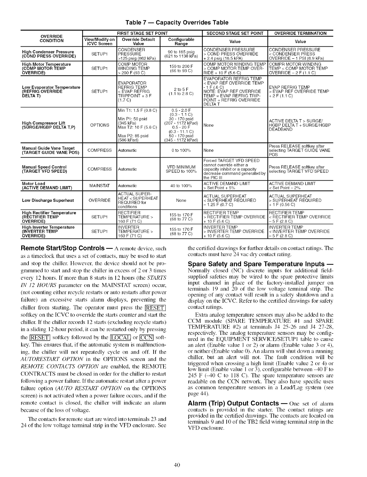
Table 7 -- Capacity Overrides Table
FIRST STAGE SET POINT SECOND STAGE SET POINT OVERRIDE TERMINATION
OVERRIDE
CONDITION View/Modify on Override Default Configurable Value Value
ICVC Screen Value Range
CONDENSER CONDENSER PRESSURE CONDENSER PRESSURE
High Condenser Pressure SETUP1 PRESSURE 90 to 165 psig > COND PRESS OVERRIDE < CONDENSER PRESS
(COND PRESS OVERRIDE) >125 psig (862 kPa) (621 to 1138 kPa) + 2.4 psig (16.5 kPA) OVERRIDE - 1 PSI (6.9 kPa)
High Motor Temperature COMP MOTOR 150 to 200 F COMP MOTOR WINDING TEMP COMPR MOTOR WINDING
(COMP MOTOR TEMP SETUP1 WINDING TEMP > COMP MOTOR TEMP OVER- TEMP < COMP MOTOR TEMP
OVERRIDE) > 2OO F (93 C) (66 to 93 C) RIDE + 10 F (5.6 C) OVERRIDE- 2 F (1.1 C)
EVAPORATOR REFRIG TEMP
EVAPORATOR < EVAP REF OVERRIDE TEMP
Low Evaporator Temperature REFRIG TEMP 2 to 5 F - 1 F (.6 C) EVAP REFRIG TEMP
(REFRIG OVERRIDE SETUP1 < EVAP REFRIG (1.1 to 2.8 C) NOTE: EVAP REF OVERRIDE > EVAP REF OVERRIDE TEMP
DELTA T) TRIPPOINT + 3 F TEMP = EVAP REFRIG TRIP- +2F(1.1C)
(1.7 C) POINT + REFRIG OVERRIDE
DELTA T
Min TI: 1.5 F (0.8 C) 0.5 - 2.0 F
(0.3- 1.1 C)
Min PI: 50 psid 30 - 170 psid ACTIVE DELTA T > SURGE/
High Compressor Lift OPTIONS (345 kPa) (207 - 1172 kPad) None HGBP DELTA T + SURGE/HGBP
(SURGE/HGBP DELTA T,P) Max T2:10 F (5.6 C) 0.5 - 20 F DEADBAND
(0.3- 11,1 C)
Max P2:85 psid 50 - 170 psid
(586 kPad) (345 - 1172 kPad)
Manual Guide Vane Target Press RELEASE softkey after
(TARGET GUIDE VANE POS) COMPRESS Automatic 0 to 100% None selecting TARGET GUIDE VANE
POS
Forced TARGET VFD SPEED
Manual Speed Control VFD MINIMUM cannot override either a Press RELEASE softkey after
capacity inhibit or a capacity selecting TARGET VFD SPEED
(TARGET VFD SPEED) COMPRESS Automatic SPEED to 100% decrease command generated by
the PIC III
Motor Load MAINSTAT Automatic 40 to 100% ACTIVE DEMAND LIMIT ACTIVE DEMAND LIMIT
(ACTIVE DEMAND LIMIT) > Set Point + 5% < Set Point - 2%
ACTUAL SUPER- ACTUAL SUPERHEAT ACTUAL SUPERHEAT
HEAT< SUPERHEAT None < SUPERHEAT REQUIRED > SUPERHEAT REQUIRED
Low Discharge Superheat OVERRIDE REQUIRED for
conditions - 1.25 F (0,7 C) + 1 F (0.56 C)
High Rectifier Temperature RECTIFIER 155 to 170 F RECTIFIER TEMP RECTIFIER TEMP
(RECTIFIER TEMP SETUP1 TEMPERATURE> (66 to 77 C) > RECTIFIER TEMP OVERRIDE < RECTIFIER TEMP OVERRIDE
OVERRIDE) 160 F (71 C) + 10 F (5,6 C) - 5 F (2.8 C)
High Inverter Temperature INVERTER 155 to 170 F INVERTER TEMP INVERTER TEMP
(INVERTER TEMP SETUP1 TEMPERATURE > > INVERTER TEMP OVERRIDE < INVERTER TEMP OVERRIDE
OVERRIDE) 160 F(71 C) (66 to 77 C) + 10 F(5,6C) -5 F(2.8C)
Remote Start/Stop Controls -- A remote device, such
as a timeclock that uses a set of contacts, may be used to stmt
and stop the chillel: Howevel; the device should not be pro-
gmmmed to st_ut and stop file chiller in excess of 2 or 3 times
every 12 hours. If more than 8 st_uts in 12 hom_ (the STARTS
IN 12 HOURS parmneter on the MAINSTAT screen) occur.
(not counting either lecycle restmts or auto restarts after power
failure) an excessive starts alarm displays, preventing the
chiller from starting. Tile operator must press the
softkey on the ICVC to override the starts counter and start the
chillel: If the chiller records 12 starts (excluding recycle starts)
in a sliding 12-hour period, it can be lestarted only by pressing
the _ softkey followed by the _ or _ soft-
key. This ensures that, if the automatic system is m_dfunction-
ing, the chiller will not repeatedly cycle on and off. If the
AUTORESTART OPTION in the OPTIONS scieen and the
REMOTE CONTACTS OPTION are enabled, the REMOTE
CONTRACTS must be closed in order for the chiller to lest_ut
following a power failure. If the automatic restmt after a power
failure option (AUTO RESTART OPTION on file OPTIONS
screen) is not activated when a power failure occurs, and if the
remote contact is closed, the chiller will indicate an _darm
because of the loss of voltage.
The contacts for remote start are wired into terminals 23 trod
24 of the low voltage terminal strip in the VFD enclosure. See
the certified drawings for further details on contact ratings. The
contacts must have 24 vac dry contact rating.
Spare Safety and Spare Temperature Inputs --
Norln_dly closed (NC) discrete inputs for addition_d field-
supplied safeties may be wired to the spare protective limits
input channel in place of the factory-installed jumper on
terminals 19 and 20 of the low voltage terminal strip. The
opening of tiny contact will result in a safety shutdown and a
display on the ICVC. Refer to the certified drawings for safety
contact ratings.
Extra amdog telnperature sensors may also be added to the
CCM module (SPARE TEMPERATURE #l and SPARE
TEMPERATURE #2) at terminals J4 25-26 and J4 27-28,
respectively. The analog temperature sensors may be config-
ured in the EQUIPMENT SERVICE/SETUPI table to cause
an alert (Enable value l or 2) or almm (Enable value 3 or 4),
or neither (Enable value 0). An alarm will shut down a running
chiller, but an alert will not. The fault condition will be
triggered when crossing a high limit (Enable value 2 or 4) or
low limit (Enable value l or 3), configurable between -40 F to
245 F (-40 Cto 118 C). The spare temperature sensors are
readable on the CCN netwoN. They also have specific uses
as common temperature sensors in a Lead/Lag system (see
page 44).
Alarm (Trip) Output Contacts -- One set of alarm
contacts is provided in file stmlel: The contact ratings are
provided in the certified drawings. The contacts are located on
terminals 9 and l0 of the TB2 field wiring terminal strip in the
VFD enclosure.
4O
Kilowatt Output -- An output is available on tile CCM
module [Terminal J8-1 (+) and J8-2 (-)1 to represent the power
consumption of the chiller Tile 4 to 20 mA signal generated by
the CCM module can be wired to the building automation or
energy management system to monitor the chiller's energy
consumption. Output is 2 mA with the chiller off. and it
varies linedy from 4 mA (representing 0% rated kilowatt
consumption) to 20 mA (representing 100% RATED LINE
KILOWATFS). The rated peak kilowatt consumption is
configured by the user in the VFD_CONF display screen by
the setting the RATED LINE KILOWATFS fiom the machine
electrical &tta nameplate.
Remote Reset of Alarms -- A stan&u'd feature of the
PIC |II controls is the ability to reset a chiller in a shutdown
alarm state from a remote location. [f the condition which
caused the alarm has cleared the chiller can be placed back into
a normal CCN operating mode when the REMOTE RESET
OPTION (ICVC_PSWD menu) is set to ENABLE. A variety
of Career Comfort Network software systems including
ComfortVIEW TM or Network Sel-v'ice Tool TM can access the
PIC III controls and reset the displayed alarm. Third party
software from building automation systems (BAS) or energy
management systems (EMS) can also access the PIC III
controls through a Carrier DataLINK rM module and reset the
fault displayed. Both methods would access the ICVC_PSWD
screen and fome the RESETALARM? point to YES to reset the
fault condition. [f the P[C III controls have determined that is
safe to start the chiller the CCN MODE? point (ICVC_PSWD
screen) can be forced to YES to place the chiller back into
norln;fl CCN operating mode. The only exceptions am the
following ahums that cannot be reset from a remote location:
Aimm/Alert STATE 100, 200, 201, 204, 206, 217-220,
233, 234, 247, and 259. To view alarm codes, refer to Trouble-
shooting Guide, Checking Display Messages, page 79. After
the alarm has been reset the PIC HI control will increment the
STARTS IN 12 HOURS counter by one upon restart. If the limit
of 8 starts in a 12-hour period is reached (Pmstart/Alert state
100), this must be reset at the local chiller control panel
(IeVC).
Condenser Pump Control -- The chiller will moni-
tor the CONDENSER PRESSURE and may turn on the con-
denser pump if the condenser pressure becomes too high while
the compressor is shut down. The COND PRESS OVERRIDE
paralneter is used to determine this pressure point. COND
PRESS OVERRIDE is found in the SETUPI display screen,
which is accessed from the EQUIPMENT SERVICE table.
The default value is 125 psig (862 kPa).
If the CONDENSER PRESSURE is greater than or equal to
the COND PRESS OVERRIDE, and the ENTERING CON-
DENSER WATER temperature is less than 115 F (46 C), the
condenser pump will energize to try to decrease the pressure
and Alert 151 will be generated. The pump will turn off when
the condenser pressure is 3.5 psi (24.1 kPa) less than the
pressure override and the CONDENSER REFRIG TEMP is
within 3 ° F (1.7 ° C)of the ENTERING CONDENSER WATER
temperature.
Condenser Freeze Prevention -- This control _dgo-
rithm helps prevent condenser tube freeze-up by energizing the
condenser pump relay. The PIC III controls the pump and, by
starting it, helps to prevent the water in the condenser fiom
freezing. The PIC III can perform this lhnction whenever the
chiller is not running excq)t when it is either actively in pump-
down or in pumpdown/lockout with the fieeze prevention
disabled.
When the chiller is off and CONDENSER REFRIG TEMP
is less than the CONDENSER FREEZE POINT, the
CONDENSER WATER PUMP will be energized (Alert State
154) Howevel, if the chiller is in pump down, and when it
entered pump down mode the CONDENSING REFRIG TEMP
was more than 5° F (2.7 ° C) above the CONDENSER
FREEZE POINT. the same low temperature condition will
generate Alarm State 244 trod the CONDENSER WATER
PUMP will be energized. In either case, the fault state will clem
and the pump will turn off when the CONDENSER REFRIG
TEMP is more than 5° F (2.7 ° C) above the CONDENSER
FREEZE POINT and the entering condenser water temperature
is greater than the CONDENSER FREEZE POINT. If the chill-
er is in Recycle Shutdown Mode when the condition occurs,
the controls will transition to a non-recycle shutdown.
Evaporator Freeze Protection -- When the EVAP-
ORATOR REFRIG TEMP is less than the EVAP REFRIG
TRIPPOINT plus the REFRIG OVERRIDE DELTA T (config-
urable fi_m 2 ° to 5°F or 1.1° to 2.8 ° C), Alert State 122 will be
displayed, and a capacity override will occm: (See Table 7.)
When the unit is running or in recycle, if the EVAPORATOR
REFRIG TEMP is equal to or less than the EVAP REFRIG
TRIPPOINT (33 ° F or 0.6 ° Cfor watek configurable for brine),
Protective Limit Alarm State 232 will be displayed, the unit
will shut down, and the CHILLED WATER PUMP will remgfin
on. The alarm will be clem'able when the leaving chilled water
temperature rises 5°F (2.8°C) above the CONTROL POINT.
When the unit is off, if the EVAPORATOR REFRIG TEMP
is less than the EVAP REFRIG TRIPPOINTplus 1° F (0.6 ° C),
Alarm State 243 will be generated and the CHILLED WATER
PUMP will be turned on. The _flmm can be reset when the
EVAPORATOR REFRIG TEMP rises 5° F (2.8 ° C) above the
EVAP REFRIG TRIPPOINT`
Tower Fan Relay Low and High -- Low condens-
er water temperature can cause the chiller to shut down when
refrigerant temperature is low. The tower fan relays, located in
the stmter, am controlled by the PIC III to energize and deener-
gize as the pressure differential between cooler and condenser
vessels changes. This prevents low condenser water tempera-
turn and maximizes chiller efficiency. The tower fan relay can
only accomplish flris if the relay has been added to the cooling
tower temperature controllel:
TOWER FAN RELAY LOW is turned on whenever the
condenser water pump is running, flow is verified, ;rod the
difference between cooler and condenser pressure is more than
30 psid (207 kPad) for entering condenser water temperature
greater than 65 F (18.3 C).
TOWER FAN RELAY LOW is turned off when the condens-
er pump is off. flow is stopped, or the EVAP REFRIGERANT
TEMP is less than the EVAP REF OVERRIDE TEMP for
ENTERING CONDENSER WATER temperature less than
62 F (16.7 C), or the difference between the CONDENSER
PRESSURE and EVAPORATOR PRESSURE is less than
25 psi d (172.4 kPad) for ENTERING CONDENSER water less
than 80 F (27 C).
TOWER FAN RELAY HIGH is turned on whenever
the condenser water pump is running, flow is verified and
the difference between EVAPORATOR PRESSURE and
CONDENSER PRESSURE is more than 35 psid (241.3 kPa)
for ENTERING COND WATER temperature greater than the
TOWER FAN HIGH SETPOINT (SETPOINT menu, default
75 F [23.9 C]).
41
TileTOWER FAN RELAY HIGH is turned off when the
condenser pump is off, flow is stopped, or the EVAPORATOR
REFRIG TEMP is less than the EVAP REF OVERRIDE TEMP
and ENTERING CONDENSER WATER is less than 70 F
(21.1 C), or the difference between EVAPORATOR PRES-
SURE and CONDENSER PRESSURE is less than 28 Psid
(193 kPa), and ENTERING CONDENSER WATER tempera-
ture is less than TOWER FAN HIGH SETPOINT minus 3 F
(-16.1 C).
Tile TOWER FAN RELAY LOW and TOWER FAN RELAY
HIGH parameters are accessed fiom the STARTUP screen.
IMPORTANT: A field-supplied water temperature control
system for condenser water should be installed. Tile system
should maintain the leaving condenser water temperature
at a temperatme that is at least 20 ° F (11 ° C) above file
leaving chilled water temperature.
The tower fan relay control is not a substitute for a con-
denser water temperature control. When used with a water
temperature control system, the tower fan relay control can
be used to help prevent low condenser water temperatures.
Auto. Restart After Power Failure -- Tiais option
may be enabled or disabled and may be viewed or modified
on the OPTIONS screen, which is accessed from the
EQUIPMENT CONFIGURATION table. If the AUTO
RESTART OPTION is enabled, the chiller will st:ut up automati-
cally after a power failure has occurred, generating one of the
following faults: single cycle dropout (if enabled), line cunent
imbalance, high line voltage, low line voltage, low DC bus
voltage, high DC bus voltage, VFD power on reset, and ICVC
power on reset (alerts 143-148, 165 and 166). With this feature
enabled, these faults _u'e treated as alerts instead of alarms, so
st_utup proceeds as soon as the condition is rectified. The 15 and
1-minute start inhibit timers are ignoled during this type of start-
up, and the STARTS IN 12 HOURS counter is not incremented.
When power is restored after file power failure and if the
compressor had been running, the oil pump will energize
for one minute before energizing the cooler pump. AUTO
RESTART will then continue like a normal start-up.
If power to the ICVC module has been off for mole than
3 hours or the timeclock has been set for the fi_t time, start the
compressor with the slowest TEMP PULLDOWN DEG/MIN
rate possible in order to minimize oil foaming.
Tile oil pump is energized occasionally during the time the
oil is being brought up to proper tempemtme in order to elimi-
nate refiigemnt that has migrated to the oil sump during the
power failure. The pump turns on for 30 seconds at the end of
every 30-minute period until the chiller is started.
Water/Brine Reset -- Chilled water capacity control is
based on achieving and maintaining a CONTROL POINT
temperatme, which is the sum of the LCWSETPOINTorECW
SETPOINT (from the SETPOINT screen) and a Water/Brine
Reset value, if any. CONTROL POINTis limited to a minimum
of 35 F (+1.7 C) for water, or 10 F (-12.2 C) for brine. Tilree
types of chilled water or brine reset are available and can be
viewed or modified on the TEMP_CTL screen, which is
accessed from the EQUIPMENT SERVICE table.
Tile ICVC default screen indicates when the chilled water
reset is active. TEMPERATURE RESET on the MAINSTAT
screen indicates the amount of reset. Tile CONTROL POINT
will be determined by adding the TEMPERATURE RESET to
the SETPOINT.
To activate a reset type, access the TEMP_CTL scleen and
input all configuration information for that reset type. Tilen,
input the reset type number (1, 2, or 3) in the SELECT/
ENABLE RESET TYPE input line.
RESET TYPE 1:4 to 20 mA (1 to 5 vdc) TEMPERATURE
RESET - Reset Type 1 is "automatic" reset utilizing a 4 to
20 mA or 1 to 5 vdc analog input signal provided from any
external sensol; controllel: or other device which is appropri-
ately configured. Reset Type 1 permits up to _+30° F (_+16.7° C)
of reset to the chilled water set point. Inputs are wired to terlni-
nals J5-3 (-) and J5-4 (+) on the CCM (for 4-20 mA input). In
order to utilize a 1 to 5 vdc input, a 250 ohln resistor must be
wired in series with the + input lead (J5-4). For either input
type, SW2 DIP switches should be set in the ON (up) position.
Inputs equivalent to less than 4 mA result in no reset, and
inputs exceeding 20 mA are treated as 20 mA.
RESET TYPE 2: REMOTE TEMPERATURE RESET --
Reset Type 2 is an automatic chilled water temperature reset
based on a remote temperature sensor input signal. Reset type
2 permits _+30 ° F (_+16° C) of automatic reset to the set point
based on a temperature sensor wired to the CCM module (see
wiring diagrams or certified diawings). The temperature sensor
must be wired to terminal J4-13 and J4-14. To configure Reset
Type 2, enter the temperature of the remote sensor at the point
where no temperature reset will occur (REMOTE TEMP ->
NO RESET). Next, enter the temperatme at which the full
amount of reset will occur (REMOTE TEMP -> FULL
RESET). Then, enter the maximum mnount of reset requiled to
operate the chiller (DEGREES RESET). Reset Type 2 can now
be activated.
RESET TYPE 3 -- Reset Type 3 is an automatic chilled water
temperature reset based on cooler temperature difference.
Reset Type 3 adds _+30° F (_+16° C) based on the temperature
diffelence between the ENTERING CHILLED WATER and
LEA VIAl(; CHILLED WATER temperature.
To configure Reset Type 3, enter the chilled water tempera-
ture difference (the difference between entering and leaving
chilled water) at which no temperature reset occurs (CHW
DELTA T-> NO RESET). Tills chilled water temperature dif-
ference is usually the full design load temperature difference.
Next, enter the difference in chilled water temperature at which
the full amount of reset occurs (CttWDELTA T-> FULL RE-
SET). Finally. enter the amount of reset (DEGREES RESET).
Reset Type 3 can now be activated.
Surge Prevention Algorithm -- This is an operator
configumble feature that can determine if lift conditions are too
high for the compressor and then take corrective action. Lift is
defined as the difference between the plessure at the impeller
eye and at the impeller discharge. Tile maximum lift a particu-
lar impeller wheel can perform varies with the gas flow
through the impeller and the dialneter of the impellec
Tile lift capability (surge line) of a v_uiable speed compres-
sor shifts upward as speed increases. Consequently. the line
which serves as the surge prevention threshold is made to shift
upward in a similar fashion as speed is increased. If the operat-
ing point goes above the surge prevention line as adjusted for
the current operating speed, then surge prevention actions are
taken. Note that the line constructed fiom SURGE/HGBP
DELTA TI, SURGE/HBBP DELTA PI, SURGE/HBBP DEL-
TA T2, and SURGE/HBBP DELTA P2 values is applied to the
full speed condition only. These surge characteristics are facto-
ry set based on the original selection, with the values printed on
a label affixed to the bottom interior face of the control panel.
Since operating conditions may affect the surge plevention al-
gorithm, some field adjustments may be necessary.
A chiller equipped with a VFD can adjust inlet guide posi-
tion or compressor speed to avoid surge (if not already at
COMPRESSOR 100% SPEED). Thus, the primary response
to entering the surge prevention region or incurring an actual
surge event (see file Surge Protection section) is to increase
complessor speed. This moves the compressor's surge line and
42
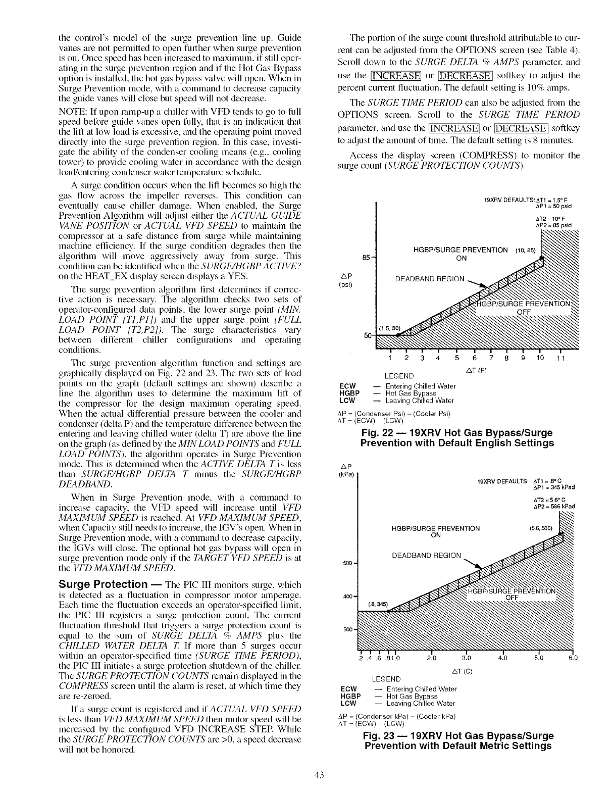
thecontrol'smodelof thesurgepreventionlineup.Guide
vanesarenotpermittedtoopenfurtherwhensurgeprevention
ison.Oncespeedhasbeenincreasedtomaximum,if stilloper-
atinginthesurgepreventionregionandif theHotGasBypass
optionisinstalled,thehotgasbypassvalvewillopen.Whenin
SurgePreventionmode,withacommandtodecreasecapacity
theguidevaneswillclosebutspeedwillnotdecrease.
NOTE:If uponromp-upachillerwithVFDtendstogotofull
speedbeforeguidevanesopenfully,that is an indication that
the lift at low load is excessive, and the operating point moved
directly into the surge prevention region. In this case, investi-
gate the ability of the condenser cooling means (e.g., cooling
tower) to provide cooling water in accor&mce with the design
load/entering condenser water temperature schedule.
A surge condition occm:s when the lift becomes so high the
gas flow across the impeller reverses. This condition can
eventu_dly cause chiller damage. When enabled, the Surge
Prevention Algorithm will adjust either the ACTUAL GUIDE
VANE POSITION or ACTUAL VFD SPEED to maintain the
complessor at a safe distance from surge while maintaining
machine efficiency. If the surge condition degrades then the
algorithm will move aggressively away from surge. This
condition can be identified when the SURGE/H(;BP ACTIVE?
on the HEAT EX display screen displays a YES.
The surge prevention algorithm first determines if correc-
tive action is necessary. The algorithm checks two sets of
operator-configured data points, the lower stage point (MIN.
LOAD POINT [T1,P1]) and the upper surge point (FULL
LOAD POINT [T2,P2]). The surge characteristics vary
between different chiller configurations and operating
conditions.
The surge prevention algorithm function and settings are
graphically displayed on Fig. 22 and 23. The two sets of load
points on the graph (default settings m'e shown) describe a
line the algorithm uses to determine the maximum lift of
the compressor for the design maximum operating speed.
When the actual differential pressme between the cooler and
condenser (delta P) and the temperature difference between the
entering and leaving chilled water (delta T) are above the line
on the graph (as defined by the MIN LOAD POINTS and FULL
LOAD POINTS), the algorithm operates in Surge Prevention
mode. This is determined when the ACTIVE DELTA T is less
than SURGE/HGBP DELTA T minus the SURGE/HGBP
DEADBAND.
When in Surge Prevention mode, with a command to
increase capacity, the VFD speed will increase until VFD
MAXIMUM SPEED is reached. At VFD MAXIMUM SPEED,
when Capacity still needs to increase, the IGV's open. When in
Surge Plevention mode, with a command to decrease capacity,
the IGVs will close. The optional hot gas bypass will open in
surge prevention mode only if the TARGET VFD SPEED is at
the VFD MAXIMUM SPEED.
Surge Protection -- The PIC III monitors surge, which
is detected as a fluctuation in compressor motor amperage.
Each time the fluctuation exceeds an operator-specified limit,
the PIC III registers a stage protection count. The current
fluctuation threshold that triggers a surge protection count is
equal to the sum of SURGE DELTA %AMPS plus the
CHILLED WATER DELTA T. If more than 5 surges occur
within an operator-specified time (SURGE TIME PERIOD),
the PIC III initiates a surge protection shutdown of the chillec
The SURGE PROTECTION COUNTS remain displayed in the
COMPRESS screen until the almm is reset, at which time they
are re-zeroed.
If a surge count is registered and if ACTUAL VFD SPEED
is less than VFD MAXIMUM SPEED then motor speed will be
increased by the configured VFD INCREASE STER While
the SURGE PROTECTION COUNTS are >0, a speed decrease
will not be honored.
The portion of the surge count threshold attributable to cur-
rent can be adjusted from the OPTIONS screen (see Table 4).
Scroll down to the SURGE DELTA %AMPS parameter, and
use the [INCREASE] or [DECREASE] softkey to adjust the
percent current fluctuation. The default setting is 10% amps.
The SURGE TIME PERIOD can also be adjusted from the
OPTIONS soeen. Scroll to the SURGE TIME PERIOD
parameter, and use the [INCREASE] or [DECREASE]softkey
to adjust the amount of time. The default setting is 8 minutes.
Access the display soeen (COMPRESS) to monitor the
surge count (SURGE PROTECTION COUNTS).
19XRV DEFAULTS:ATt =1.5= F
AP1 =50 psid
AT2 = llY" F
AP2 = 85 psid
_p
(psi)
85-
50-
HGBP/SURGE PREVENTION (lo, 85)
ON
DEADBAND REGION ,
1 2 3 4 5 6 7 8 9 10 1 1
AT (F)
LEGEND
ECW -- Entering Chilled Water
HGBP -- Hot Gas Bypass
LOW -- Leaving Chilled Water
AP = (Condenser Psi) -(Cooler Psi)
AT = (ECW) - (LCW)
Fig. 22-- 19XRV Not Gas Bypass/Surge
Prevention with Default English Settings
zxp
(kPa)
19XRV DEFAULTS: AT1 =.8° C
APt = 345 kPad
AT2 = 5.6° C
AP2 = 586 kPad
HGBP/SURGE PREVENTION (&6, 586)
ON
DEADBAND REGION
500-
400-
300-
.2 A.6 .81,0 2.0 3.0 4.0 5.0 6.0
&T (C)
LEGEND
ECW -- Entering Chilled Water
RGBP -- Hot Gas Bypass
LOW -- Leaving Chilled Water
AP = (Condenser kPa) - (Cooler kPa)
AT = (ECW) - (LCW)
Fig. 23 i 19XRV Hot Gas Bypass/Surge
Prevention with Default Metric Settings
43
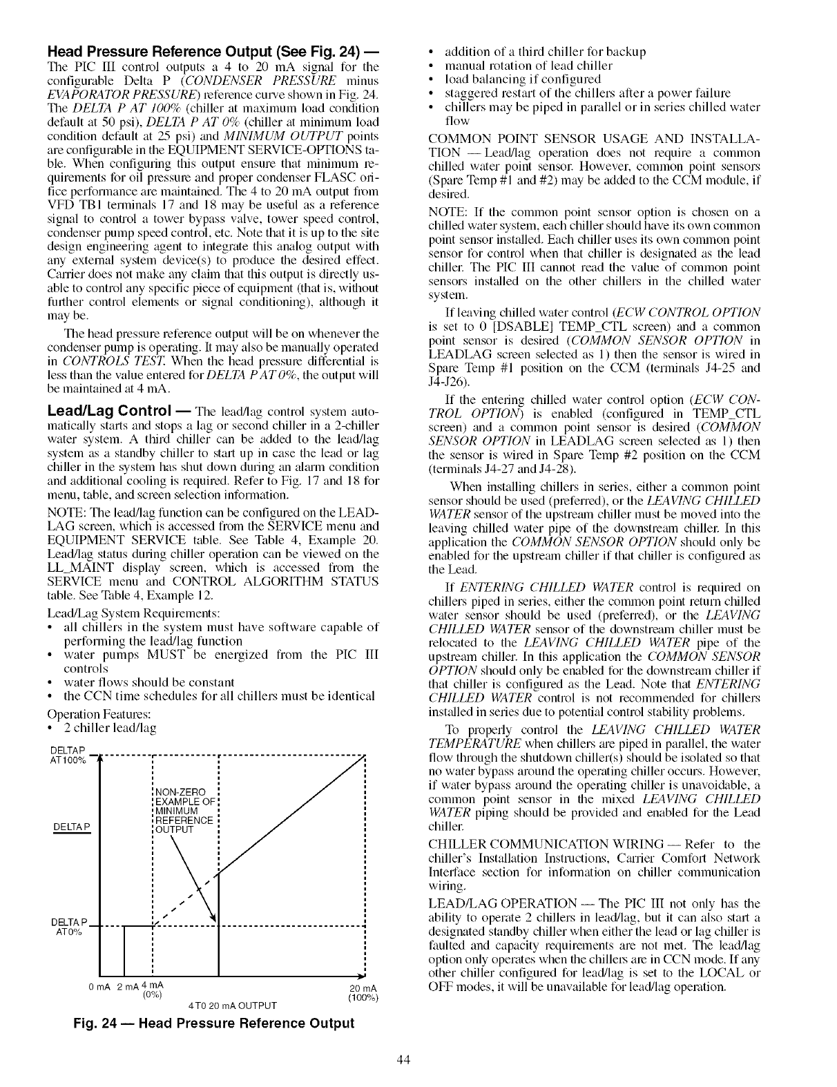
Head Pressure Reference Output (See Fig. 24) --
The PIC [II control outputs a 4 to 20 mA signal for the
configurable Delta P (CONDENSER PRESSURE minus
EVAPORATOR PRESSURE) leference cmwe shown in Fig. 24.
The DELTA P AT 100% (chiller at maximum load condition
default at 50 psi), DELTA P AT 0% (chiller at minimum load
condition default at 25 psi) trod MINIMUM OUTPUT points
are configurable in the EQUIPMENT SERVICE-OPTIONS ta-
ble. When configuring this output ensure that minimum re-
quirements for oil pressure and proper condenser FLASC on-
lice performance are mtdntained. The 4 to 20 mA output from
VFD TBI terminals 17 and 18 may be useful as a reference
signal to control a towel bypass valve, tower speed control,
condenser pump speed control, etc. Note that it is up to the site
design engineering agent to integrate this analog output with
any external system device(s) to produce the desired effect.
Carrier does not make any claim that this output is directly us-
able to control any specific piece of equipment (that is, without
further control elements or signal conditioning), although it
may be.
The head pressure reference output will be on whenever the
condenser pump is operating. It may also be manually operated
in CONTROLS TEST. When the head pressure differential is
less than the value entered forDELTA PATO%, the output will
be maintained at 4 mA.
Lead/Lag Control -- The lead/lag control system auto-
matically starts and stops a lag or second chiller in a 2-chiller
water system. A third chiller can be added to the lead/lag
system as a standby chiller to start up in case the lead or lag
chiller in the system has shut down during an ahum condition
and additional cooling is required. Refer to Fig. 17 and 18 for
menu, table, and screen selection information.
NOTE: The lead/lag function can be configured on the LEAD-
LAG screen, which is accessed from the SERVICE menu and
EQUIPMENT SERVICE table. See Table 4, Example 20.
Lead/lag status during chiller operation can be viewed on the
LL_MAINT display screen, which is accessed from the
SERVICE menu and CONTROL ALGORITHM STATUS
table. See Table 4, Example 12.
Lead/Lag System Requirements:
• all chillers in the system must have software capable of
performing the lead/lag function
• water pumps MUST be energized from the PIC III
controls
• water flows should be constant
•the CCN time schedules for all chillers must be identical
Operation Features:
• 2chiller lead/lag
DELTAP
AT100% "3
DELTA P
DELTA P__
AT0%
lNON-ZERO
',EXAMPLE OF
' M N MUM
',REFERENCE
',OUTPUT
s" a"
i t
===7 = ..........
0mA 2 mA4mA
(O%) 4T0 20 mA OUTPUT
Fig. 24- Head Pressure Reference Output
]11
20 mA
(100%)
• addition of a third chiller for backup
• manual rotation of lead chiller
• load balancing if configured
• staggered restart of the chillers after a power failure
• chillers may be piped in parallel or in series chilled water
flow
COMMON POINT SENSOR USAGE AND INSTALLA-
TION- Lead/lag operation does not require a common
chilled water point sensor However. common point sensors
(Spare Temp #1 and #2) may be added to the CCM module, if
desired.
NOTE: If the common point sensor option is chosen on a
chilled water system, each chiller should have its own common
point sensor installed. Each chiller uses its own common point
sensor for control when that chiller is designated as the lead
chillel: The PIC III cannot read the value of common point
sensors installed on the other chillers in the chilled water
system.
If leaving chilled water control (ECW CONTROL OPTION
is set to 0 [DSABLEI TEMP CTL screen) and a common
point sensor is desired (COMMON SENSOR OPTION in
LEADLAG screen selected as 1) then the sensor is wired in
Spare Temp #1 position on the CCM (terminals J4-25 and
J4-J26).
If the entering chilled water control option (ECW CON-
TROL OPTION) is enabled (configured in TEMP_CTL
screen) and a common point sensor is desired (COMMON
SENSOR OPTION in LEADLAG screen selected as 1) then
the sensor is wired in Spare Temp #2 position on the CCM
(terminals J4-27 and J4-28).
When installing chillers in series, either a common point
sensor should be used (preferred), or the LEAVING CHILLED
WATER sensor of the upstremn chiller must be moved into the
leaving chilled water pipe of the downstream chillel: In this
application the COMMON SENSOR OPTION should only be
enabled for the upstremn chiller if that chiller is configured as
the Lead.
If ENTERING CHILLED WATER control is required on
chillers piped in series, either the common point return chilled
water sensor should be used (preferred), or the LEAVING
CHILLED WATER sensor of the downstream chiller must be
relocated to the LEAVING CHILLED WATER pipe of the
upstream chiller. In this application the COMMON SENSOR
OPTION should only be enabled for the downstream chiller if
that chiller is configured as the Lead. Note that ENTERING
CHILLED WATER control is not recommended for chillers
installed in series due to potential control stability problems.
To properly control the LEAVING CHILLED WATER
TEMPERATURE when chillers me piped in parallel, the water
flow through the shutdown chiller(s) should be isolated so that
no water bypass around the operating chiller occurs. However.
if water bypass around the operating chiller is unavoi&_ble, a
common point sensor in the mixed LEAVING CHILLED
WATER piping should be provided and enabled for the Lead
chillel:
CHILLER COMMUNICATION WIRING -- Refer to the
chiller's Installation Instructions, Cmrier Comfort Network
Interface section for infommtion on chiller communication
wiring.
LEAD/LAG OPERATION- The PIC III not only has the
ability to operate 2 chillers in lead/lag, but it can also start a
designated standby chiller when either the lead or lag chiller is
faulted and capacity requirements are not met. The lead/lag
option only operates when the chillel_ are in CCN mode. If any
other chiller configured for lead/lag is set to the LOCAL or
OFF modes, it will be unavailable for lead/lag operation.
44
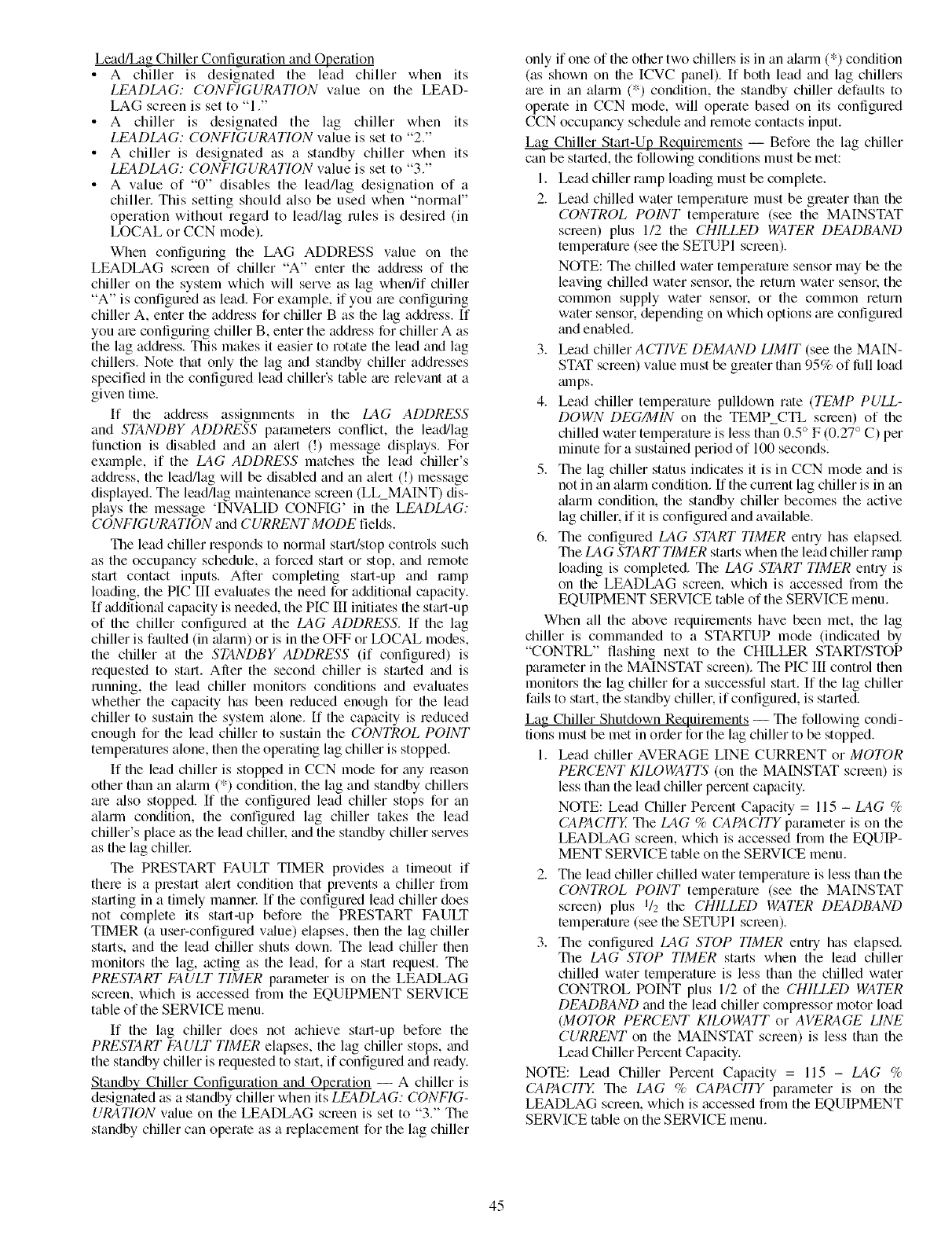
Lead/Lag Chiller Configuration and Operation
• A chiller is designated the lead chiller when its
LEADLAG: CONFIGURATION value on the LEAD-
LAG screen is set to "1 ."
• A chiller is designated the lag chiller when its
LEADLAG: CONFIGURATION value is set to "2."
• A chiller is designated as a standby chiller when its
LEADLAG: CONFIGURATION value is set to "3."
• A value of "0" disables the lead/lag designation of a
chiller. This setting should also be used when "normal"
operation without regard to lead/lag rules is desired (in
LOCAL or CCN mode).
When configuring the LAG ADDRESS value on the
LEADLAG screen of chiller "A" enter the address of the
chiller on the system which will serve as lag when/if chiller
"A" is configured as lead. For example, if you ale configuring
chiller A, enter the address for chiller B as file lag address. [f
you ale configuring chiller B, enter the addiess for chiller A as
the lag address. This makes it easier to rotate the lead and lag
chillers. Note that only the lag and standby chiller addresses
specified in the configmed lead chiller's table me relevant at a
given time.
If file address assignlnents in the LAG ADDRESS
and STANDBY ADDRESS parameters conflict, the lead/lag
function is disabled and an alert (!) message displays. For
example, if the LAG ADDRESS matches the lead chiller's
addiess, the lead/lag will be disabled and an alert (!) message
displayed. The lead/lag maintenance screen (LL_MAINT) dis-
plays the message 'INVALID CONFIG' in the LEADLAG:
CONFIGURATION and CURRENT MODE fields.
The lead chiller responds to normal start/stop controls such
as the occupancy schedule, a forced start or stop, and lemote
start contact inputs. After completing stmt-up and ramp
loading, the PIC III evaluates the need for additional capacity.
If additional capacity is needed, the PIC III initiates the stmt-up
of the chiller configured at the LAG ADDRESS. If the lag
chiller is faulted (in _darm) or is in the OFF or LOCAL modes,
the chiller at file STANDBY ADDRESS (if configured) is
requested to start. After the second chiller is stmted and is
running, the lead chiller monitors conditions and evaluates
whether the capacity has been reduced enough for the lead
chiller to sustain the system alone. If the capacity is reduced
enough for file lead chiller to sustain the CONTROL POINT
temperatures alone, then the operating lag chiller is stopped.
If the lead chiller is stopped in CCN mode for tiny reason
other than an almm (*) condition, the lag and standby chillers
are also stopped. If the configured lead chiller stops for an
alarln condition, the configured lag chiller takes the lead
chiller's place as the lead chillel: and the standby chiller serves
as the lag chillel:
The PRESTART FAULT TIMER provides a timeout if
there is a prestart alert condition that prevents a chiller from
starting in a timely mannel: If the configured lead chiller does
not complete its start-up before the PRESTART FAULT
TIMER (a user-configured v_due) elapses, then the lag chiller
starts, and the lead chiller shuts down. The lead chiller then
monitors the lag, acting as the lead, for a stm't request. The
PRESTART FAULT TIMER parameter is on the LEADLAG
screen, which is accessed fi_m the EQUIPMENT SERVICE
table of the SERVICE menu.
If the lag chiller does not achieve start-up before the
PRESTART FAULT TIMER elapses, the lag chiller stops, and
the standby chiller is requested to start, if configured and ready.
Standby Chiller Configuration and Operation -- A chiller is
designated as a standby chiller when its LEADLAG: CONFIG-
URATION wdue on the LEADLAG screen is set to "3." The
standby chiller can operate as a replacement for the lag chiller
only if one of the other two chillel_ is in an alarm (*) condition
(as shown on file ICVC panel). If both lead and lag chillers
me in an alarm (*) condition, the standby chiller defaults to
operate in CCN mode, will operate based on its configured
CCN occupancy schedule and remote contacts input.
Lag Chiller Start-Up Requirements -- Before the lag chiller
can be started, the following conditions must be met:
1. Lead chiller ramp loading must be complete.
2. Lead chilled water temperature must be greater than the
CONTROL POINT temperature (see the MAINSTAT
screen) plus 1/2 the CHILLED WATER DEADBAND
temperature (see the SETUPI screen).
NOTE: The chilled water telnperature sensor may be the
leaving chilled water sensor, the return water sensol: the
common supply water sensor, or the common return
water sensor, depending on which options are configured
and enabled.
3. Lead chiller ACTIVE DEMAND LIMIT (see the MAIN-
STAT screen) value must be greater than 95% of lhll load
mnps.
4. Lead chiller telnperature pulldown rate (TEMP PULL-
DOWN DEG_IN on the TEMP_CTL screen) of the
chilled water temperature is less than 0.5 ° F (0.27 ° C) per
minute for a susttdned period of 100 seconds.
5. The lag chiller status indicates it is in CCN mode and is
not in an alarm condition. If the current lag chiller is in tin
alarm condition, the standby chiller becomes the active
lag chiller, if it is configured and available.
6. The configured LAG START TIMER entry has elapsed.
The LAG START TIMER stmts when the lead chiller rmnp
loading is completed. The LAG START TIMER entry is
on the LEADLAG screen, which is accessed from the
EQUIPMENT SERVICE table of the SERVICE menu.
When all the above requirements have been met, file lag
chiller is commanded to a STARTUP mode (indicated by
"CONTRL" flashing next to the CHILLER START/STOP
parameter in the MAINSTAT screen). The PIC III control then
monitors the lag chiller for a successful stark If the lag chiller
fails to start, the standby chiller, if configured, is started.
Lag Chiller Shutdown Requirements -- The following condi-
tions must be met in order for the lag chiller to be stopped.
1. Lead chiller AVERAGE LINE CURRENT or MOTOR
PERCENT KILOWATTS (on the MAINSTAT screen) is
less than the lead chiller percent capacity.
NOTE: Lead Chiller Pement Capacity = 115 - LAG %
CAPACITY The LAG %CAPACITY parameter is on the
LEADLAG screen, which is accessed from the EQUIP-
MENT SERVICE table on the SERVICE menu.
2. The lead chiller chilled water temperature is less than the
CONTROL POINT temperature (see the MAINSTAT
screen) plus I/2 the CHILLED WATER DEADBAND
temperature (see the SETUPI screen).
3. The configured LAG STOP TIMER entry has elapsed.
The LAG STOP TIMER starts when the lead chiller
chilled water temperature is less than file chilled water
CONTROL POINT plus 1/2 of the CHILLED WATER
DEADBAND trod the lead chiller compressor motor load
(MOTOR PERCENT KILOWATT or AVERAGE LINE
CURRENT on the MAINSTAT screen) is less than the
Lead Chiller Percent Capacity.
NOTE: Lead Chiller Percent Capacity = 115 - LAG %
CAPACITY The LAG % CAPACITY parameter is on the
LEADLAG screen, which is accessed fi_>mthe EQUIPMENT
SERVICE table on the SERVICE menu.
45
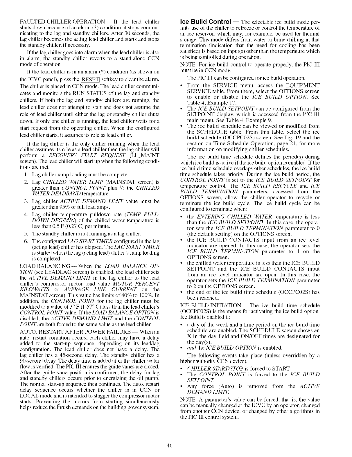
FAULTED CHILLER OPERATION --If file lead chiller
shuts down because of an alarm (*) condition, it stops commu-
nicating to the lag and standby chillers. After 30 seconds, the
lag chiller becomes the acting lead chiller and starts and stops
the standby chiller, if necessary.
If the lag chiller goes into alarm when file lead chiller is also
in aimm, the standby chiller reverts to a stand-alone CCN
mode of operation.
If the lead chiller is in an alarm (*) condition (as shown on
tile ICVC panel), press tile _ softkey to clear tile alarm.
The chiller is placed in CCN mode. The lead chiller communi-
cates and monitors the RUN STATUS of the lag and standby
chillers. If both the lag and standby chillers are running, the
lead chiller does not attempt to start and does not assume the
role of lead chiller until either the lag or standby chiller shuts
down. If only one chiller is running, the lead chiller waits for a
stmt request from the operating chiller When the configured
lead chiller stm-ts,it assumes its role as lead chillel:
If the lag chiller is the only chiller running when the lead
chiller assumes its role as a lead chiller then the lag chiller will
perfoml a RECOVERY START REQUEST (LL_MAINT
screen). The lead chiller will stmt up when the following condi-
tions am met.
1. Lag chiller romp loading must be complete.
2. Lag CHILLED WATER TEMP (MAINSTAT screen) is
greater than CONTROL POINT plus q2 the CHILLED
WATER DEADBAND temperature.
3. Lag chiller ACTI1/E DEMAND LIMIT value must be
gleater than 95% of full load amps.
4. Lag chiller temperature pulldown rate (TEMP PULL-
DOWN DEG/MIN) of the chilled water temperature is
less than 0.5 F (0.27 C) per minute.
5. The standby chiller is not running as a lag chiller.
6. The configured LAG START TIMER configured in the lag
(acting lead) chiller has elapsed. The LAG START TIMER
is sttu-ted when the lag (acting lead) chiller's romp loading
is completed.
LOAD BALANCING--When the LOAD BALANCE OP-
TION (see LEADLAG screen) is enabled, the lead chiller sets
the ACTI1/E DEMAND LIMIT in the lag chiller to the lead
chiller's compressor motor load value MOTOR PERCENT
KILOWATTS or AVERAGE LINE CURRENT on the
MAINSTAT screen). This value has limits of 40% to 100%. In
addition, the CONTROL POINT for the lag chiller must be
modified to a value of 3° F (1.67 ° C) less than the lead chiller's
CONTROL POINT value. If the LOAD BALANCE OPTION is
disabled, the ACTIVE DEMAND LIMIT and the CONTROL
POINTme both forced to the sallle value as the lead chillel:
AUTO. RESTART AFTER POWER FAILURE -- When an
auto. restart condition occurs, each chiller may have a delay
added to the stm-t-up sequence, depending on its lead/lag
configuration. The lead chiller does not have a delay. The
lag chiller has a 45-second delay. The standby chiller has a
90-second delay. The delay time is added after the chiller water
flow is verified. The PIC III ensures the guide vanes me closed.
After the guide vane position is confirmed, the delay for lag
and standby chillers occurs prior to energizing the oil pump.
The normtd start-up sequence then continues. The auto. rests.u1
delay sequence occurs whether the chiller is in CCN or
LOCAL mode and is intended to stagger the compressor motor
sttu-ts. Preventing the motors from st_uling simultaneously
helps reduce the inrush demands on the building power system.
lee Btlih:l Control -- The selectable ice build mode per-
mits use of the chiller to refmeze or control the temperature of
an ice mselwoir which may, for example, be used for thermtd
storage. This mode differs from water or brine chilling in flint
terlnination (indication that the need for cooling has been
satisfied) is based on input(s) other than the temperature which
is being controlled during operation.
NOTE: For ice build control to operate properly, the PIC HI
must be in CCN mode.
The PIC III can be configured for ice build operation.
• From the SERVICE menu, access the EQUIPMENT
SERVICE table. From there, select the OPT'IONS screen
to enable or disable the ICE BUILD OPTION. See
Table 4, Example 17.
• The ICE BUILD SETPOINT can be configured from the
SETPOINT display, which is accessed fiom the PIC III
main menu. See Table 4, Example 9.
• The ice build schedule can be viewed or modified from
the SCHEDULE table. From this table, select the ice
build schedule (OCCPC02S) screen. See Fig. 19 and the
section on Time Schedule Operation, page 21, for morn
information on modifying chiller schedules.
The ice build time schedule defines the period(s) during
which ice build is active if the ice build option is enabled. If the
ice build time schedule overlaps other schedules, the ice build
time schedule takes priority. During the ice build period, the
CONTROL POINT is set to the ICE BUILD SETPOINT for
temperature control. The ICE BUILD RECYCLE and ICE
BUILD TERMINATION parameters, accessed from the
OPTIONS screen, allow the chiller operator to recycle or
terminate the ice build cycle. The ice build cycle can be
configured to terminate when:
• the ENTERING CHILLED WATER temperature is less
than the ICE BUILD SETPOINZ In this case, the opera-
tor sets the ICE BUILD TERMINATION parameter to 0
(the default setting) on the OPTIONS screen.
• the ICE BUILD CONTACTS input from an ice level
indicator are opened. In this case, the operator sets the
ICE BUILD TERMINATION parameter to 1 on the
OPTIONS screen.
• the chilled water temperature is less than the ICE BUILD
SETPOINT and the ICE BUILD CONTACTS input
from an ice level indicator are open. In this case, the
operator sets the ICE BUILD TERMINATION parameter
to 2 on the OPTIONS screen.
• the end of the ice build time schedule (OCCPC02S) has
been reached.
ICE BUILD INITIATION--The ice build time schedule
(OCCPC02S) is the means for activating the ice build option.
Ice Build is enabled if:
• a day of the week and a time period on the ice build time
schedule are enabled. The SCHEDULE screen shows an
X in the day field and ON/OFF times are designated for
the day(s),
•a,_d the ICE BUILD OPTION is enabled.
The following events take place (unless overridden by a
higher authority CCN device).
•CHILLER START/STOP is forced to START.
• The CONTROL POINT is forced to the ICE BUILD
SETPOINT.
• Any force (Auto) is removed from the ACTIVE
DEMAND LIMIT.
NOTE: A pmameter's value can be forced, that is, file vtdue
can be manually changed tit the ICVC by tin operatok changed
fiom another CCN device, or changed by other algorithms in
the PIC III control system.
46
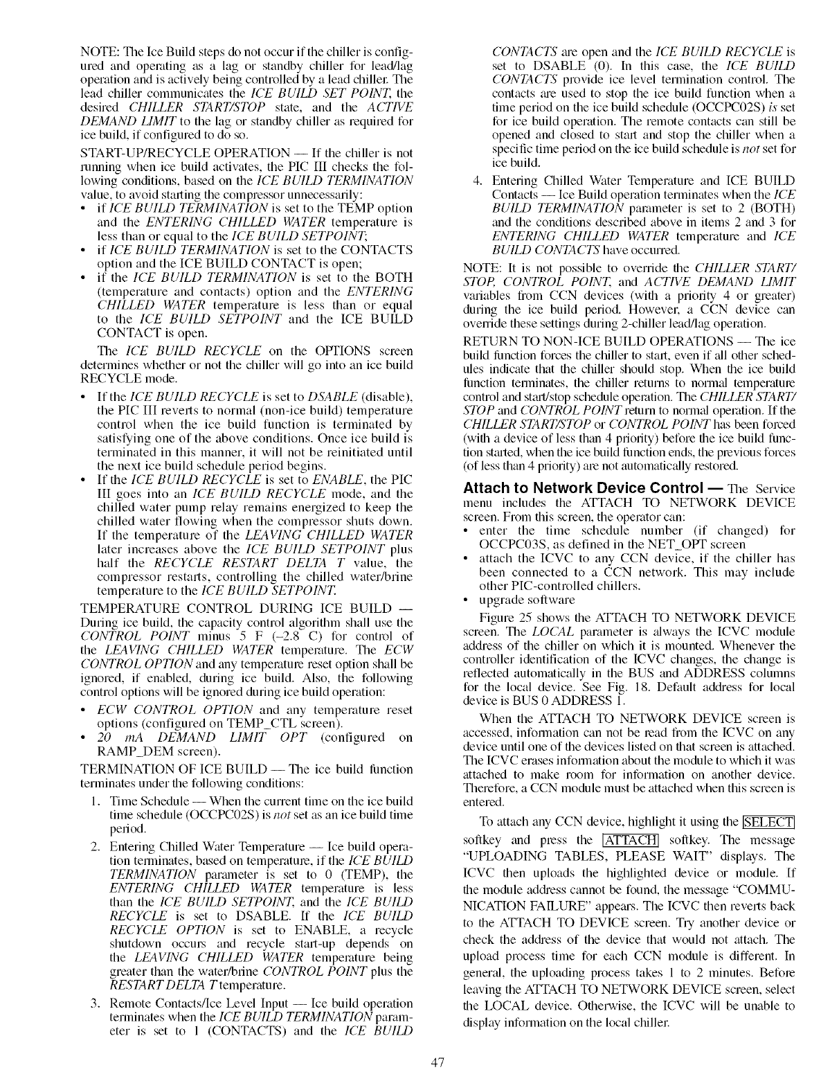
NOTE:TheIceBuildstepsdonotoccurif thechillerisconfig-
uredandoperatingasa lagor standbychillerfor lead/lag
operationandisactivelybeingcontrolledbyaleadchillerThe
leadchillercommunicatestheICE BUILD SET POINZ the
desired CHILLER START/STOP state, and the ACTIVE
DEMAND LIMIT to the lag or standby chiller as required for
ice build, if configured to do so.
START-UP/RECYCLE OPERATION -- If the chiller is not
running when ice build activates, the HC III checks the fol-
lowing conditions, based on the ICE BUILD TERMINATION
value, to avoid starting the compressor unnecessarily:
• if ICE BUILD TERMINATION is set to the TEMP option
and the ENTERING CHILLED WATER temperature is
less than or equal to the ICE BUILD SETPOINT;
• if ICE BUILD TERMINATION is set to the CONTACTS
option and the ICE BUILD CONTACT is open;
• if the ICE BUILD TERMINATION is set to the BOTH
(temperature and contacts) option and the ENTERING
CHILLED WATER temperature is less than or equal
to the ICE BUILD SETPOINT and the ICE BUILD
CONTACT is open.
The ICE BUILD RECYCLE on the OPTIONS screen
determines whether or not the chiller will go into an ice build
RECYCLE mode.
• If the ICE BUILD RECYCLE is set to DSABLE (disable),
the HC III reverts to normal (non-ice build) temperature
control when the ice build function is terminated by
satisfying one of the above conditions. Once ice build is
terminated in this manner, it will not be reinitiated until
the next ice build schedule period begins.
• If the ICE BUILD RECYCLE is set to ENABLE, the PIC
III goes into an ICE BUILD RECYCLE mode, and the
chilled water pump relay remains energized to keep the
chilled water flowing when the compressor shuts down.
If the temperature of the LEA1/ING CHILLED WATER
later increases above the ICE BUILD SETPOINT plus
half the RECYCLE RESTART DELTA T value, the
compressor restarts, controlling the chilled water/brine
temperature to the ICE BUILD SETPOINT.
TEMPERATURE CONTROL DURING ICE BUILD --
During ice build, the capacity control algorithm shall use the
CONTROL POINT minus 5 F (-2.8 C) for control of
the LEAVING CHILLED WATER temperature. The ECW
CONTROL OPTION and any temperature reset option shall be
ignored, if enabled, during ice build. Also, the following
control options will be ignored during ice build operation:
•ECW CONTROL OPTION and any temperature reset
options (confiigured on TEMP_CTL screen).
•20 mA DEMAND LIMIT OPT (configured on
RAMP_DEM screen).
TERMINATION OF ICE BUILD -- The ice build lhnction
terminates under the following conditions:
1. Time Schedule --When the current time on the ice build
time schedule (OCCPC02S) is i,ot set as an ice build time
period.
2. Entering Chilled Water Temperature -- Ice build opera-
tion terminates, based on temperature, if the ICE BUILD
TERMINATION paralneter is set to 0 (TEMP), the
ENTERING CHILLED WATER temperature is less
than the ICE BUILD SETPOINT. and the ICE BUILD
RECYCLE is set to DSABLE. ff the ICE BUILD
RECYCLE OPTION is set to ENABLE, a recycle
shutdown occms and recycle start-up depends on
the LEA1/ING CHILLED WATER temperature being
greater than the water/brine CONTROL POINT plus the
RESTART DELTA Ttemperature.
3. Remote Contacts/Ice Level Input -- Ice build operation
terminates when the ICE BUILD TERMINATION param-
eter is set to 1 (CONTACTS) and the ICE BUILD
CONTACTS me open and the ICE BUILD RECYCLE is
set to DSABLE (0). In this case, the ICE BUILD
CONTACTS provide ice level termination control. The
contacts m'e used to stop the ice build function when a
time period on the ice build schedule (OCCPC02S) is set
for ice build operation. The remote contacts can still be
opened and closed to start and stop the chiller when a
specific time period on the ice build schedule is not set for
ice build.
4. Entering Chilled Water Temperature and ICE BUILD
Contacts --Ice Build operation terminates when the ICE
BUILD TERMINATION parameter is set to 2 (BOTH)
and the conditions described above in items 2 and 3 for
ENTERING CHILLED WATER temperature and ICE
BUILD CONTACTS have occurred.
NOTE: It is not possible to override file CHILLER START/
STOP, CONTROL POINE and ACTIVE DEMAND LIMIT
variables from CCN devices (with a priority 4 or greater)
during the ice build period. Howevel: a CCN device can
override these settings during 2-chiller lead/lag operation.
RETURN TO NON-ICE BUILD OPERATIONS -- Tile ice
build lunction forces the chiller to start, even if _dl other sched-
ules indicate that file chiller should stop. When file ice build
lunction terminates, the chiller returns to normal temperatme
control and st_u't!stop schedule operation. The CHILLER START/
STOP and CONTROL POINT return to normal operation. If the
CHILLER START/STOP or CONTROL POINT has been forced
(wifll a device of less than 4 priority) before file ice build func-
tion stmted, when the ice build lunction ends, the plevious forces
(of less than 4 priority) me not automatic_dly restored.
Attach to Network Device Control -- _qle Service
menu includes the ATTACH TO NETWORK DEVICE
screen. From this screen, the operator can:
• enter the time schedule number (if changed) for
OCCPC03S, as defined in the NET_OPT screen
• attach the ICVC to any CCN device, if the chiller has
been connected to a CCN network. This may include
other PIC-controlled chillers.
• upgrade software
Figure 25 shows the ATTACH TO NETWORK DEVICE
screen. The LOCAL parameter is _dways the ICVC module
address of the chiller on which it is mounted. Whenever the
controller identification of the ICVC changes, the change is
reflected automatically in the BUS and ADDRESS columns
for the local device. See Fig. 18. Default addiess for local
device is BUS 0 ADDRESS 1.
When the ATFACH TO NETWORK DEVICE screen is
accessed, infomlation can not be lead from the ICVC on any
device until one of the devices listed on that screen is attached.
The ICVC erases information about the module to which it was
attached to make room for information on another device.
Therefore, a CCN module must be attached when this screen is
entered.
To attach any CCN device, highlight it using the
softkey and press the ]ATTACH] sollkey. The message
"UPLOADING TABLES, PLEASE WAIT' displays. The
ICVC then uploads the highlighted device or module. If
the module addi'ess cannot be found, the message "COMMU-
NICATION FAILURE" appems. The ICVC then reverts back
to the ATTACH TO DEVICE screen. Try another device or
check the addiess of the device that would not attach. The
upload process time for each CCN module is different. In
gener_d, the uploading process takes 1 to 2 minutes. Befole
leaving the ATTACH TO NETWORK DEVICE screen, select
the LOCAL device. Otherwise, the ICVC will be unable to
display information on the local chillel:
47
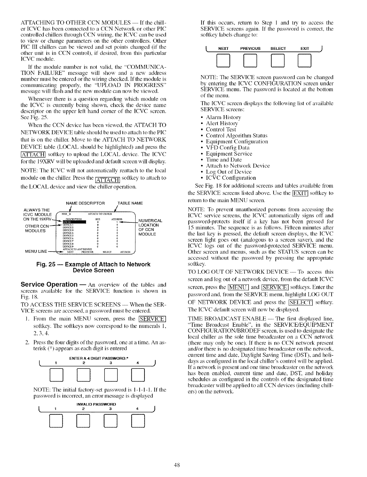
ATTACHINGTOOTHERCCNMODULES-- If thechill-
erICVChasbeenconnectedtoaCCNNetworkorotherPIC
controlledchillel.sthroughCCNwiring,theICVCcanbeused
tovieworchangeptuametersontheothercontrollers.Other
PICIII chillerscanbeviewedandsetpointschanged(if the
otherunitisin CCNcontrol),if desired,fromthisparticular
ICVCmodule.
If themodulenumberisnotvalid,the"COMMUNICA-
TIONFAILURE"messagewill showanda newad&ess
numbermustbeenteredorthewiringchecked.If filemoduleis
communicatingproperly,the"UPLOADIN PROGRESS"
messagewillflashandfilenewmodulecannowbeviewed.
Wheneverthereisaquestionregardingwhichmoduleon
theICVCiscunentlybeingshown,checkthedevicename
descriptorontheupperlefthandcornerof theICVCscreen.
SeeFig.25.
WhentheCCNdevicehasbeenviewed,theATI'ACHTO
NETWORKDEVICEtableshouldbeusedtoattachtothePIC
thatisonthechillel:MovetotheATFACHTONETWORK
DEVICEtable(LOCALshouldbehighlighted)andpressthe
softkeytouploadtheLOCALdevice.TheICVC
forthe19XRVwillbeuploadedanddefaultscreenwilldisplay.
NOTE:TheICVCwillnotautomaticallyreattachtothelocal
moduleonthechillel:Pressthe_ soflkeytoattachto
theLOCALdeviceandviewthechilleroperation.
NAME DESCRIPTOR TABLE NAME
ALWAYS THE ![ /
ICVC MODULE(" l_x_ j_ ,vrrAc'H-_o_v_c_ "XI
ON THE 19XRV-_ r_l_cR1r,_ON _US A_r_R_SS | _,_H_mc-aJ
I _ tll_llllllllllll_ 0 _ _---.----,_ ............
OTH E R CCN _ DEvicesi 0_ / LOCATION
k._ _ _ OFCCN
MODULES/ o_,_a o /
|....... _/MODULE
NVICE 8 o o
I_VlCE _ 0 0
Fig. 25 -- Example of Attach to Network
Device Screen
Service Operation -- An overview of the tables and
screens available for the SERVICE function is shown in
Fig. 18.
TO ACCESS THE SERVICE SCREENS -- When the SER-
VICE screens are accessed, a password must be entered.
1. From the main MENU screen, press the [SERVICE]
soflkey. The soflkeys now correspond to the numerals 1,
2,3,4.
2. Press the four digits of the password, one at a time. An as-
terisk (*) appetus as each digit is entered
ENTER A4DIGIT PASSWORD:*
NOTE: The initial factory-set password is 1-1-1-1. If the
password is incorrect, an error message is displayed
INVALID PASSWORD
If fl_is occurs, return to Step 1 and try to access the
SERVICE screens again. If the password is correct, the
softkey labels change to:
NEXT PREVIOUS SELECT EXIT
F--IF--I
NOTE: The SERVICE screen password can be changed
by entering the ICVC CONFIGURATION screen under
SERVICE menu. The password is located at the bottom
of the menu.
The [CVC screen displays the following list of available
SERVICE screens:
• Alarm History
• Alert History
• Control Test
• Control Algorithm Status
• Equipment Configuration
• VFD Config Data
• Equipment Service
• Time and Date
• Attach to Network Device
• Log Out of Device
• ICVC Configuration
See Fig. 18 for additional screens and tables available from
the SERVICE screens listed above. Use the _ softkey to
return to the main MENU screen.
NOTE: To prevent unauthorized pe_.sons D_m accessing the
ICVC service screens, the ICVC automatically signs off and
password-protects itself if a key has not been pressed for
15 minutes. The sequence is as follows. Filleen minutes after
the last key is pressed, the default screen displays, the ICVC
screen light goes out (analogous to a screen saver), and the
ICVC logs out of the password-protected SERVICE menu.
Other screen and menus, such as the STATUS screen can be
accessed without the password by pressing the appropriate
softkey.
TO LOG OUT OF NETWORK DEVICE -- To access this
screen and log out of a network device, from the default ICVC
screen, press the _ and [SERVICE] softkeys. Enter the
password and, flom the SERVICE menu, highlight LOG OUT
OF NETWORK DEVICE and press the _ softkey.
The ICVC default screen will now be displayed.
TIME BROADCAST ENABLE -- The first displayed line,
"Time Broadcast Enable", in the SERVICE/EQUIPMENT
CONFIGURATION/BRODEF screen, is used to designate the
loc_d chiller as the sole time broadcaster on a CCN network
(there may only be one). If there is no CCN network present
and/or there is no designated time broadcaster on the netwoN,
current time and date, Daylight Saving Time (DST), and holi-
days as configured in the local chiller's control will be applied.
If a network is present and one time broadcaster on the network
has been enabled, current time and date, DST. and holi&ty
schedules as configured in the controls of the designated time
broadcaster will be applied to all CCN devices (including chill-
ers) on the network.
48
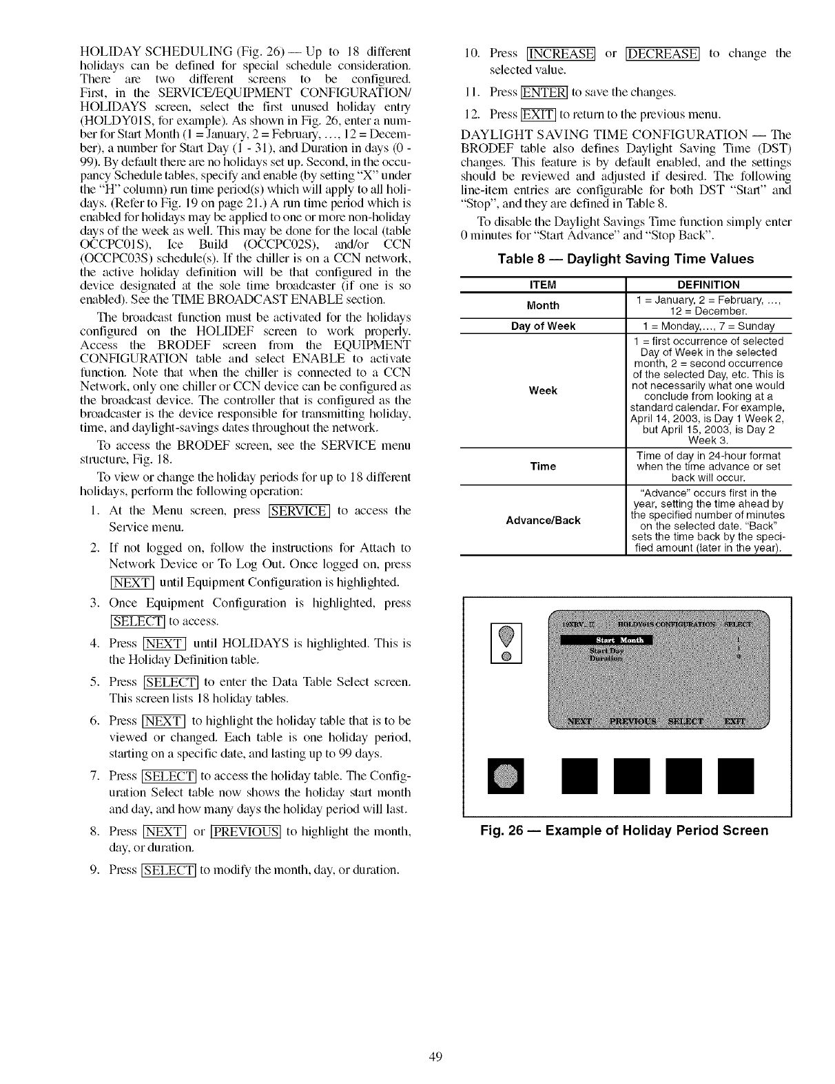
HOLIDAYSCHEDULING(Fig.26)-- Upto 18different
holidayscanbedefinedfor specialscheduleconsideration.
Thereale two differentscreensto be configured.
Filet,in theSERVICE/EQUIPMENTCONFIGURATION/
HOLIDAYSscreen,selectthefil_t unusedholidayently
(HOLDY01S,forexmnple).AsshowninFig.26,enteranum-
berforSt_u-tMonth(1=January,2=February..... 12=Decem-
ber),anumberforStartDay(1- 31),andDurationindays(0-
99).Bydefaulttherealenoholidayssetup.Second,intheoccu-
pancyScheduletables,specifyandenable(bysetting"X"under
the"H"column)runtimeperiod(s)whichwillapplytoallholi-
days.(RefertoFig.19onpage21.)A runtimeperiodwhichis
enabledforholidaysmaybeappliedtooneormorenon-holiday
daysoftheweekaswell.Thismaybedoneforthelocal(table
OCCPC01S),Ice Build (OCCPC02S),trod/orCCN
(OCCPC03S) schedule(s). If the chiller is on a CCN netwoN,
the active holiday definition will be that configured in the
device designated at the sole time broadcaster (if one is so
enabled). See the TIME BROADCAST ENABLE section.
The broadcast function must be activated for the holidays
configured on the HOLIDEF screen to work properly.
Access the BRODEF screen fi_)m the EQUIPMENT
CONFIGURATION table and select ENABLE to activate
function. Note that when the chiller is connected to a CCN
Network, only one chiller or CCN device c_m be configured as
the broadcast device. The controller that is configured as the
broadcaster is the device responsible for transmitting holiday,
time, and daylight-savings dates throughout the network.
To access the BRODEF screen, see the SERVICE menu
structure, Fig. 18.
To view or change the holiday periods for up to 18 different
holidays, perform the following operation:
1. At the Menu screen, press [SERVICE] to access the
Service menu.
2. If not logged on, follow the instructions for Attach to
Network Device or To Log Out. Once logged on, press
until Equipment Configuration is highlighted.
3. Once Equipment Configuration is highlighted, press
_to access.
4. Press _ until HOLIDAYS is highlighted. This is
the Holiday Definition table.
5. Press _ to enter the Data Table Select screen.
This screen lists 18 holiday tables.
6. Press _ to highlight the holiday table that is to be
viewed or changed. Each table is one holiday period,
stm-tingon a specific date, and lasting up to 99 days.
7. Press _ to access the holiday table. The Config-
uration Select table now shows the holiday start month
and day. and how many days the holiday period will last.
8. Pless _ or [PREVIOUS] to highlight tfie month,
day, or duration.
9. Press _ to modify the month, day, or duration.
10. Press IINCREASEI or IDECREASEI to change the
selected value.
11. Press _ to save the changes.
12. Press _ to return to the previous menu.
DAYLIGHT SAVING TIME CONFIGURATION -- The
BRODEF table also defines Daylight Saving Time (DST)
changes. This feature is by default enabled, and the settings
should be reviewed and adjusted if desired. The following
line-item entries ;ue configurable for both DST "Stall" and
"Stop", and they are defined in Table 8.
To disable the Daylight Savings Time function simply enter
0 minutes for "Start Advance" and "Stop Back".
Table 8 -- Daylight Saving Time Values
ITEM
Month
Day of Week
Week
Time
Advance/Back
DEFINITION
1 = January. 2 = February .....
12 = December.
1 = Monday...., 7 = Sunday
1 = first occurrence of selected
Day of Week in the selected
month, 2 = second occurrence
of the selected Day, etc. This is
not necessarily what one would
conclude from looking at a
standard calendar. For example,
April 14, 2003, is Day 1 Week 2,
but April 15, 2003, is Day 2
Week 3.
Time of day in 24-hour format
when the time advance or set
back will occur.
"Advance" occurs first in the
year, setting the time ahead by
the specified number of minutes
on the selected date. "Back"
sets the time back by the speci-
fied amount (later in the year).
Fig. 26 -- Example of Holiday Period Screen
49
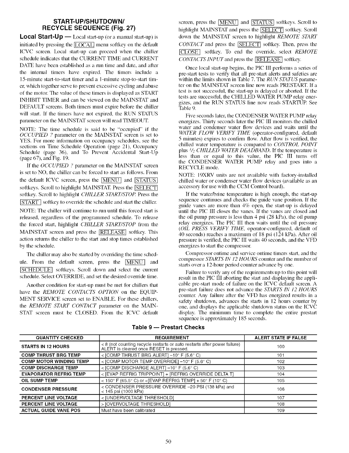
START-UP/SHUTDOWN/
RECYCLE SEQUENCE (Fig. 27)
Local Start-Up -- L_cal start-up (ora manual start-up) is
initiated by pressing the _ menu softkey on the default
ICVC scleen. Ix_c_d start-up can proceed when the chiller
schedule indicates that the CURRENT TIME and CURRENT
DATE have been established as a mn time and date, and after
the internal timers have expired. The timers include a
15-minute start-to-start timer and a l-minute stop-to-start tim-
el. which together serve to prevent excessive cycling and abuse
of the motol: The value of these timers is displayed as START
INHIBIT TIMER and can be viewed on the MAINSTAT and
DEFAULT screens. Both timel_ must expire before the chiller
will stall. If the timers have not expired, the RUN STATUS
pm'ameter on the MAINSTAT screen will read TIMEOUT.
NOTE: The time schedule is said to be "occupied" if the
OCCUPIED ? pmameter on the MAINSTAT scleen is set to
YES. For more information on occupancy schedules, see the
sections on Time Schedule Operation (page 21), Occupancy
Schedule (page 36), and To Prevent Accidental Stall-Up
(page 67), and Fig. 19.
If the OCCUPIED ? pm'ameter on the MAINSTAT screen
is set to NO, the chiller can be forced to stm't as follows. From
the default [CVC screen, press the _ and
softkeys. Scroll to highlight MAINSTAT. Pless the
softkey. Scroll to highlight CHILLER START/STOP. Press the
softkey to override the schedule and start the chiflel:
NOTE: The chiller will continue to run until this forced start is
released, regardless of the progrmnmed schedule. To release
the forced start, highlight CHILLER START/STOP fiom the
MAINSTAT screen and press the [RELEASE] softkey. This
action returns the chiller to the stmt and stop times established
by the schedule.
The chiller may also be stmted by overriding the time sched-
ule. From the default screen, press the _ and
[SCHEDULE] softkeys. Scroll down and select the current
schedule. Select OVERRIDE, and set the desiled override time.
Another condition for st;ut-up must be met for chillers that
have the REMOTE CONTACTS OPTION on the EQUIP-
MENT SERVICE screen set to ENABLE. For these chillers,
the REMOTE START CONTACT parameter on the MAIN-
STAT screen must be CLOSED. From the ICVC default
screen, press the _ and _ softkeys. Scroll to
highlight MAINSTAT and press the _ softkey. Scroll
down the MAINSTAT screen to highlight REMOTE START
CONTACT and press the _ softkey. Then, press the
softkey. To end the override, select REMOTE
CONTACTS INPUT and press the [RELEASE ] softkey.
Once local start-up begins, the PIC III performs a series of
pre-start tests to verify that all pre-start alefls and safeties are
within the limits shown in Table 7. The RUN STATUS parame-
ter on the MAINSTAT screen line now reads PRESTART. If a
test is not successful, the start-up is delayed or aborted. If the
tests are successful, the CHILLED WATER PUMP relay ener-
gizes, and the RUN STATUS line now reads STARTUR See
Table 9.
Five seconds latel', the CONDENSER WATER PUMP relay
energizes. Thirty seconds later the PIC III monitors the chilled
water trod condenser water flow devices and waits until the
WATER FLOW VERIFY TIME (operator-configured, default
5 minutes) expires to confirm flow. After flow is verified, the
chilled water temperature is compmed to CONTROL POINT
plus/_ CHILLED WATER DEADBAND. If the temperature is
less than or equal to this value, the PIC III turns off
the CONDENSER WATER PUMP relay and goes into a
RECYCLE mode.
NOTE: 19XRV units are not available with factou-installed
chilled water or condenser water flow devices (available as an
accesso Ufor use with the CCM Control board).
If the water/brine temperature is high enough, the st;u't-up
sequence continues and checks the guide vane position. If the
guide vanes are more than 4% open, the stall-up is delayed
until the PIC IIl closes the vanes. If the vanes are closed and
the oil pump pressure is less than 4 psi (28 kPa), the oil pump
relay energizes. The PIC [II then waits until the oil pressure
(OIL PRESS VERIFY TIME, operator-configured, default of
40 seconds) leaches a maximum of 18 psi (124 kPa). After oil
pressure is verified, the PIC III waits 40 seconds, and the VFD
energizes to start the compressol:
Compressor ontime and service ontime timers start, and the
complessor STARTS IN 12 HOURS counter and the number of
stalls over a 12-hour period counter advance by one.
Ftfilure to verily any of the requirements up to this point will
result in the PIC III aborting the stall and displaying the appli-
cable pre-start mode of failure on the ICVC default screen. A
pre-start failure does not advance the STARTS IN 12 HOURS
countel: Any failure after the VFD has energized results in a
safety shutdown, advances the starts in 12 hours counter by
one, and displays the applicable shutdown status on the [CVC
display. The minimum time to complete the entire prestart
sequence is approximately 185 seconds.
Table 9 -- Prestart Checks
QUANTITY CHECKED
STARTS IN 12 HOURS
COMP THRUST BRG TEMP
COMP MOTOR WINDING TEMP
COMP DISCHARGE TEMP
EVAPORATOR REFRIG TEMP
OIL SUMP TEMP
CONDENSER PRESSURE
PERCENT LINE VOLTAGE
PERCENT LINE VOLTAGE
ACTUAL GUIDE VANE POS
REQUIREMENT
< 8 (not counting recycle restarts or auto restarts after power failure)
ALERT is cleared once RESET is pressed.
< [COMP THRUST BRG ALERT] -10 ° F (5.6° C)
< [COMP MOTOR TEMP OVERRIDE] -10 ° F (5.6 ° C)
< [COMP DISCHARGE ALERT] -10 ° F (5.6 ° C)
< [EVAP REFRIG TRIPPOINT] + [REFRIG OVERRIDE DELTA T]
< 150 ° F (65.5 ° C) or <[EVAP REFRIG TEMP] + 50 ° F (10 ° C)
< CONDENSER PRESSURE OVERRIDE -20 PSI (138 kPa) and
< 145 psi (1000 kPa)
< [UNDERVOLTAGE THRESHOLD]
> [OVERVOLTAGE THRESHOLD]
Must have been calibrated
ALERT STATE
100
101
102
103
104
105
106
107
108
109
IF FALSE
5O
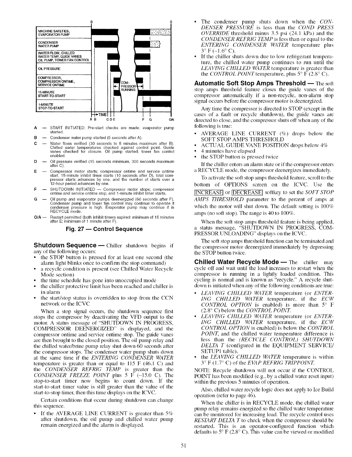
MACHINE SAFETIES,
EVAPORATOR PUMP
CONDENSER
WATER PUMP
WATER FLOW, CHILLED
WATER TEMP, GUIDE VANES
OIL PUMP,TOWER FAN CONTROL
OIL PRESSURE
COMPRESSOR,
COMPRESSOR ONTIME,
SERVICE ONTIME
15-MINUTE
START*TO-START
1-MINUTE
STOP-TO-START *'TIME
ODE
3OM-
_RESSC
tUNNIN
I !
II
F G O/A
A -- START INITIATED: Pre-start checks are made; evaporator pump
started,
B -- Condenser water pump started (5 seconds after A),
C -- Water flows verified (30 seconds to 5 minutes maximum after B).
Chilled water temperatures checked against control point, Guide
vanes checked for closure, Oil pump started; tower fan control
enabled.
D -- Oil pressure verified (15 seconds minimum, 300 seconds maximum
after C).
E -- Compressor motor starts; compressor ontime and service ontime
start, 15-minute inhibit timer starts (10 seconds after D), total com-
pressor starts advances by one, and the number of starts over a
12-hour period advances by one.
F -- SHUTDOWN INITIATED -- Compressor motor stops; compressor
ontime and service ontime stop, and 1-minute inhibit timer starts.
G -- Oil pump and evaporator pumps deenergized (60 seconds after F).
Condenser pump and tower fan control may continue to operate if
condenser pressure is high. Evaporator pump may continue if in
RECYCLE mode.
O/A-- Restart permitted (both inhibit timers expired: minimum of 15 minutes
after E; minimum of 1 minute after F).
Fig. 27 -- Control Sequence
Shutdown Sequence--Chiller shutdown begins if
any of the following occurs:
• the STOP button is pressed for at least one second (the
alarm light blinks once to confirm the stop command)
• a recycle condition is present (see Chilled W_tter Recycle
Mode section)
• the time schedule has gone into unoccupied mode
•the chiller protective limit has been reached and chiller is
in alarm
• the start/stop status is overridden to stop from the CCN
network or the [CVC
When a stop signfd occurs, the shutdown sequence first
stops the compressor by deactivating the VFD output to the
motor A status message of "SHUTDOWN IN PROGRESS,
COMPRESSOR DEENERGIZED" is displayed, and the
comptessor ontime and service ontime stop. The guide vanes
are then brought to the closed position. The oil pump relay and
the chilled water/brine pump telay shut down 60 seconds after
the compressor stops. The condenser water pump shuts down
at the same time if the ENTERING CONDENSER WATER
temperature is greater than or equal to 115 F (46.1 C) find
the CONDENSER REFRIG TEMP is greater titan the
CONDENSER FREEZE POINT plus 5 F (-15.0 C). The
stop-to-statl timer now begins to count down. If the
statl-to-stmt timer value is still greater than the value of the
start-to-stop timet: then this time displays on the ICVC.
Certain conditions that occur during shutdown can change
this sequence.
• [f the AVERAGE LINE CURRENT is greater than 5%
alter shutdown, the oil pump and chilled water pump
remain energized and the alarm is displayed.
•The condenser pump shuts down when the CON-
DENSER PRESSURE is less than the COND PRESS
OVERRIDE threshold minus 3.5 psi (24.1 kPa) and the
CONDENSER REFRIG TEMP is less than or equal to the
ENTERING CONDENSER WATER temperature plus
3° F (-1.6° C).
• If the chiller shuts down due to low refl'igerant tempera-
ture, the chilled water pump continues to run until the
LEAVING (/HILLED WATER temperature is greater than
the CONTROL POINTtemperature, plus 5° F (2.8 ° C).
Automatic Soft Stop Amps Threshold -- The soft
stop fillips threshold feature closes the guide vanes of the
compressor automaticfflly if a non-recycle, non-alarm stop
signal occurs before the compressor motor is deenergized.
Any time the compressor is directed to STOP (except in the
cases of a fault or recycle shutdown), the guide vanes ate
directed to close, and the compressor shuts off when any of the
following is true:
• AVERAGE LINE CURRENT (%) drops below the
SOFT STOP AMPS THRESHOLD
• ACTUAL GUIDE VANE POSITION drops below 4%
• 4 minutes have elapsed
• the STOP button is pressed twice
If file chiller enters an alarm state or if the compressor enters
a RECYCLE mode, the compressor deenergizes immediately.
To activate the soft stop amps threshold feature, scroll to the
bottom of OPTIONS screen on the [CVC. Use the
[INCREASE] or [DECREASE[ softkey to set the SOFT STOP
AMPS THRESHOLD parmneter to the percent of amps at
which the motor will shut down. The default setting is 100%
alnps (no soft stop). The range is 40 to 100%.
When the soft stop amps threshold feature is being applied,
a status message, "SHUTDOWN IN PROGRESS, COM-
PRESSOR UNLOADING" displays on the ICVC.
The soft stop amps threshold function can be terminated and
the compressor motor deenergized immediately by depressing
the STOP button twice.
Chilled Water Recycle Mode-- The chiller may
cycle off and wait until the load increases to restart when the
compressor is running in a lightly loaded condition. This
cycling is norlnal and is known as "recycle." A recycle shut-
down is initiated when any of the following conditions are true:
•LEA1/ING CHILLED WATER temperature (or ENTER-
ING CHILLED WATER temperature, if the ECW
CONTROL OPTION is enabled) is more than 5° F
(2.8 ° C) below the CONTROL POINT.
•LEAI/ING CHILLED WATER temperature (or ENTER-
ING CHILLED WATER temperature, if the ECW
CONTROL OPTION is enabled) is below the CONTROL
POINT. and the chilled water temperature difference is
less than the (RECYCLE CONTROL) SHUTDOWN
DELTA T (configured in the EQUIPMENT SERVICE/
SETUPI table).
• the LEA1/ING (/HILLED WATER temperature is within
3° F (1.7 ° C) of the EI/AP REFRIG TRIPPOINT.
NOTE: Recycle shutdown will not occur if the CONTROL
POINT has been modified (e.g., by a chilled water reset input)
within the previous 5 minutes of operation.
Also, chilled water recycle logic does not apply to Ice Build
operation (refer to page 46).
When the chiller is in RECYCLE mode, the chilled water
pump relay remains energized so the chilled water temperatute
can be monitored for increasing load. The recycle control uses
RESTART DELTA T to check when the compressor should be
restarted. This is an opettltor-configured function which
defaults to 5° F (2.8 ° C). This value can be viewed or modified
51
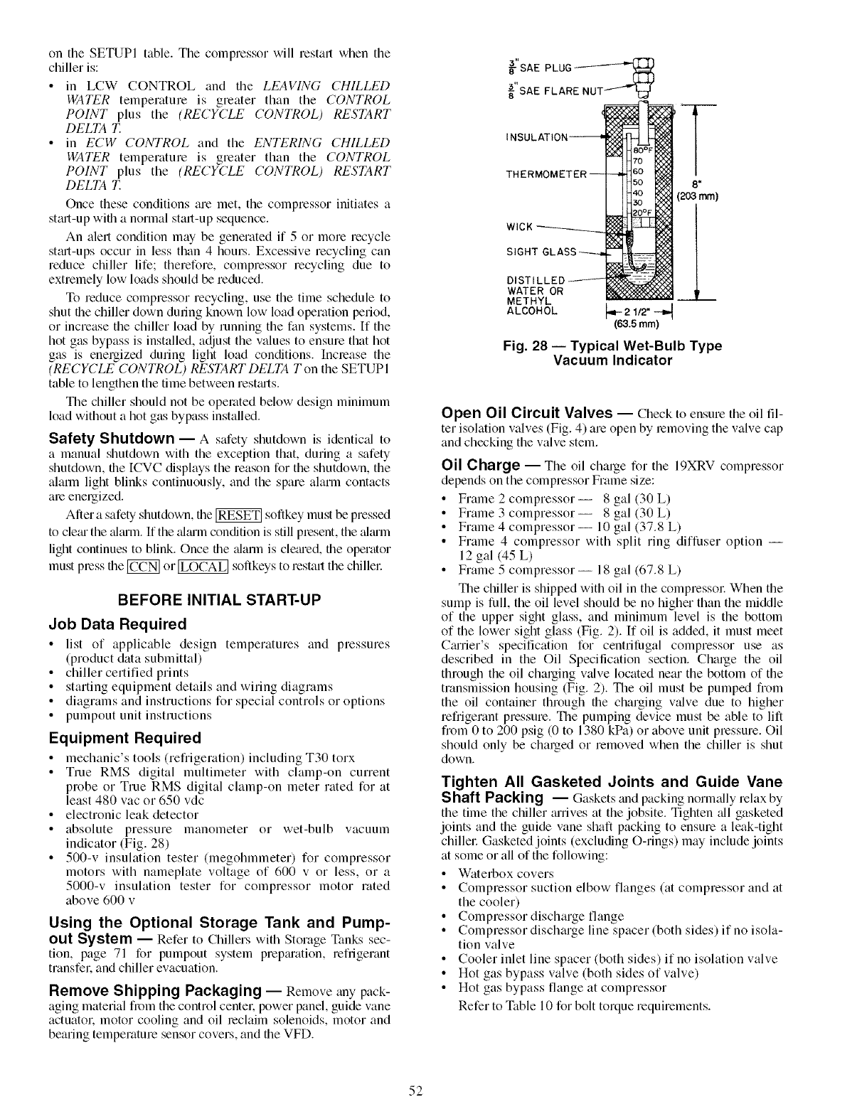
ontheSETUPItable.Thecompressorwillrestartwhenthe
chilleris:
• in LCW CONTROLandthe LEAVING (7HILLED
WATER temperature is greater than the CONTROL
POINT plus the (RECYCLE CONTROL) RESTART
DELTA T.
• in ECW CONTROL and the ENTERING CHILLED
WATER temperature is greater than the CONTROL
POINT plus the (RECYCLE CONTROL) RESTART
DELTA T.
Once these conditions am met, the compressor initiates a
st_ut-up with a normal start-up sequence.
An alert condition may be generated if 5 or more recycle
stmt-ups occur in less than 4 hom.s. Excessive recycling can
reduce chiller life; therefore, compressor recycling due to
extremely low loads should be reduced.
To reduce compressor recycling, use the time schedule to
shut file chiller down dunng known low load operation period,
or incmase the chiller load by running the fan systems. If the
hot gas bypass is installed, adjust the values to ensum that hot
gas is energized during light load conditions. Increase the
(RECYCLE CONTROL) RESTART DELTA T on the SETUPI
table to lengthen the time between restmts.
The chiller should not be operated below design minimum
load without a hot gas bypass installed.
Safety Shutdown- A safety shutdown is identic_d to
a manual shutdown with the exception that, during a safety
shutdown, the ICVC displays the mason for the shutdown, the
alarm light blinks continuously, and the spare alarm contacts
am energized.
After a safety shutdown, the _ soflkey must be pressed
to clem the ahum. If the ahum condition is still present, the _dmln
light continues to blink. Once file ;tlarm is clemed, file operator
must press the _ or_ softkeys to restart the chillel:
BEFORE INITIAL START-UP
Job Data Required
• list of applicable design temperatums and pressures
(product data submittal)
• chiller certified prints
• starting equipment details and wiring diagrams
• diagrams and instructions for special controls or options
• pumpout unit instructions
Equipment Required
• mechanic's tools (refrigeration) including T30 torx
• True RMS digital multimeter with clamp-on current
probe or True RMS digital clamp-on meter rated for at
least 480 vac or 650 vdc
• electronic leak detector
• absolute pressure manometer or wet-bulb vacuum
indicator (Fig. 28)
• 500-v insulation tester (megohmmeter) for compressor
motors with nameplate voltage of 600 v or less, or a
5000-v insulation tester for compressor motor rated
above 600 v
Using the Optional Storage Tank and Pump-
out System -- Refer to Chillers with Storage Tanks sec-
tion, page 71 for pumpout system prepmation, refngerant
transfeL and chiller evacuation.
Remove Shipping Packaging -- Remove any pack-
aging material from the control centeL power panel, guide vane
actuatoL motor cooling and oil reclaim solenoids, motor and
bearing temperatum sensor covers, and the VFD.
_'SAE PLUG_
_"SAE FLARENUT I_-
THERMC 8"
(203 mm)
SIGHT
DISTI
WATER OR
METHYL
ALCOHOL
Fig. 28 -- Typical Wet-Bulb Type
Vacuum Indicator
Open Oil Circuit Valves -- Check to ensure the oil fil-
ter isolation valves (Fig. 4) am open by removing the valve cap
and checking the valve stem.
Oil Charge -- The oil chmge for the 19XRV compmssor
depends on the compressor Frame size:
• Frame 2 compressor-- 8 gal (30 L)
• Frame 3 compressor-- 8 gal (30 L)
• Frame 4 compressor-- 10 gal (37.8 L)
• Frame 4 compressor with split ring diffuser option --
12 gal (,45 L)
• Frame 5 compressor-- 18 gal (67.8 L)
The chiller is shipped with oil in the compressor When the
sump is full, the oil level should be no higher than the middle
of the upper sight glass, and minimum level is the bottom
of the lower sight glass (Fig. 2). [f oil is added, it must meet
C_urier's specification for centrilhgal compressor use as
described in the Oil Specification section. Charge the oil
through the oil charging valve located near the bottom of the
transmission housing (Fig. 2). The oil must be pumped from
the oil container through file charging valve due to higher
refrigerant pressure. The pumping device must be able to lift
from 0 to 200 psig (0 to 1380 kPa) or above unit pressure. Oil
should only be charged or removed when the chiller is shut
down.
Tighten All Gasketed Joints and Guide Vane
Shaft Packing -- Gaskets ;rod packing normally relax by
the time the chiller rerives at the jobsite. Tighten all gasketed
joints and the guide vane shaft packing to ensum a leak-tight
chillel: Gasketed joints (excluding O-rings) may include joints
at some or all of the following:
•Waterbox covers
•Compressor suction elbow flanges (at compressor and at
the cooler)
•Compressor discharge flange
•Compressor discharge line spacer (both sides) if no isola-
tion valve
•Cooler inlet line spacer (both sides) if no isolation valve
• Hot gas bypass valve (both sides of valve)
• Hot gas bypass flange at compressor
Refer to Table 10 for bolt torque requimments.
52
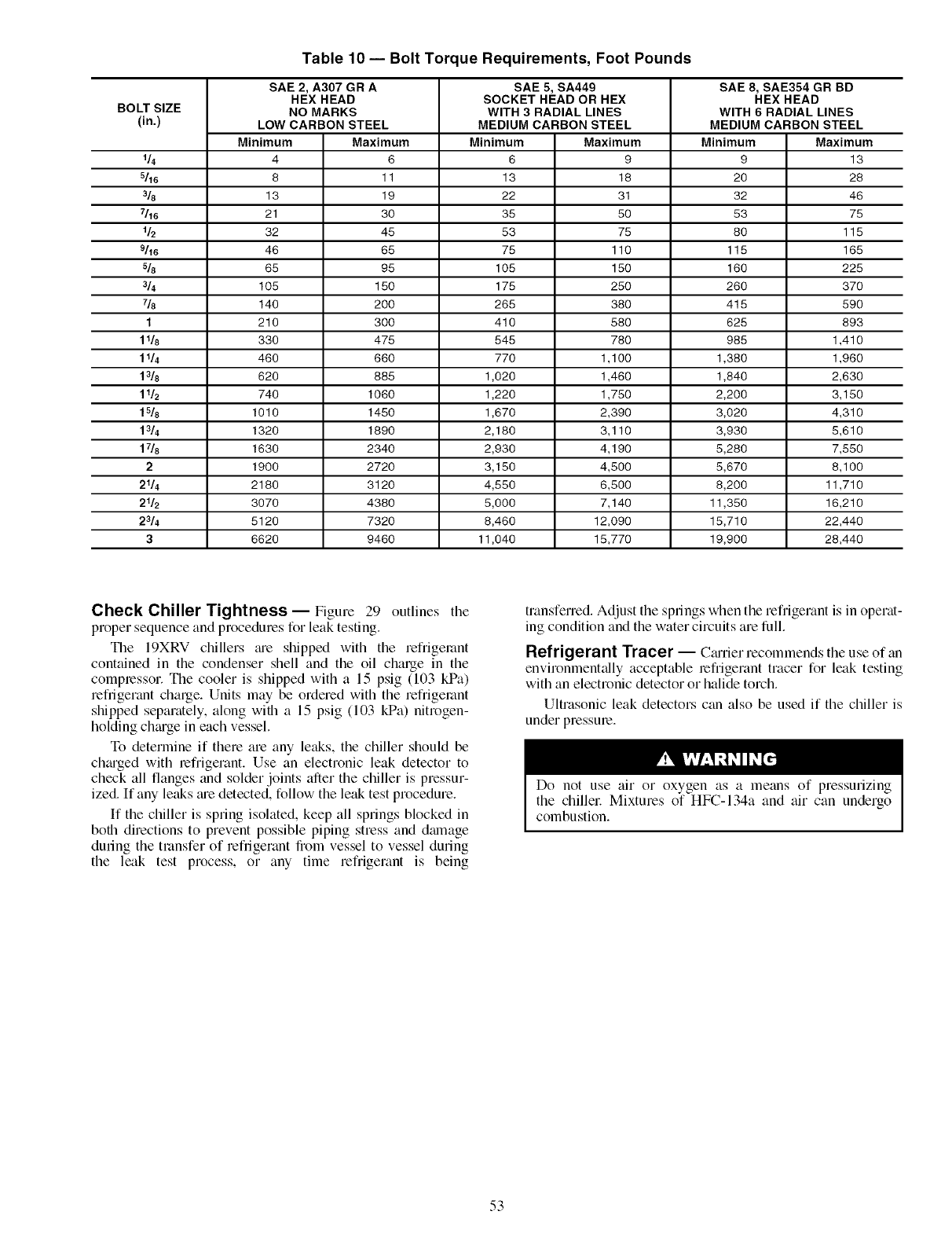
Table 10- Bolt Torque Requirements, Foot Pounds
SAE 2, A307 GR A SAE 5, SA449 SAE 8, SAE354 GR BD
HEX HEAD SOCKET HEAD OR HEX HEX HEAD
BOLT SIZE NO MARKS WITH 3 RADIAL LINES WITH 6 RADIAL LINES
(in.) LOW CARBON STEEL MEDIUM CARBON STEEL MEDIUM CARBON STEEL
Minimum Maximum Minimum Maximum Minimum Maximum
1_ 4 6 6 9 9 13
_16 8 11 13 18 20 28
318 13 19 22 31 32 46
_16 21 30 35 50 53 75
l& 32 45 53 75 80 115
_16 46 65 75 110 115 168
5/8 68 95 105 150 160 225
314 105 150 175 250 260 370
718 140 200 265 380 415 590
1 210 300 410 580 625 893
1 l& 330 475 545 780 985 1,410
11/4 460 660 770 1,100 1,380 1,960
13/8 620 885 1,020 1,460 1,840 2,630
1 l& 740 1060 1,220 1,750 2,200 3,150
1 s/8 101 O 1450 1,670 2,390 3,020 4,31 O
1_4 1320 1890 2,180 3,110 3,930 5,610
17/8 1630 2340 2,930 4,190 5,280 7,550
2 1900 2720 3,150 4,500 5,670 8,100
2114 2180 3120 4,550 6,500 8,200 11,710
216 3070 4380 5,000 7,140 11,350 16,210
2_4 5120 7320 8,460 12,090 15,710 22,440
3 6620 9460 11,040 15,770 19,900 28,440
Check Chiller Tightness-- Figure 29 outlines tile
proper sequence and procedures for leak testing.
The 19XRV chillers me shipped with the refrigerant
contained in the condenser shell and the oil charge in the
compressor. The cooler is shipped with a 15 psig (103 kPa)
refrigerant charge. Units may be ordered with the refiigemnt
shipped separately, along with a 15 psig (103 kPa) nitrogen-
holding chmge in each vessel.
To determine if there are any leaks, the chiller should be
chmged with refrigerant. Use an electronic leak detector to
check all flanges and solder joints after the chiller is pressur-
ized. If any leaks me detected, follow the leak test procedure.
If the chiller is spring isolated, keep all springs blocked in
both directions to prevent possible piping stress and dmnage
during the transfer of refrigerant from vessel to vessel during
the leak test process, or any time refrigerant is being
transferred. Adjust the springs when the refrigerant is in operat-
ing condition and the water circuits are full.
Refrigerant Tracer -- C_urier recommends the use of an
environment_dly acceptable refrigerant tracer for leak testing
with an electronic detector or halide torch.
Ultrasonic leak detectors can also be used if the chiller is
under pressure.
Do not use air or oxygen as a means of pressurizing
the chillel: Mixtures of HFC-134a and air can undergo
combustion.
53
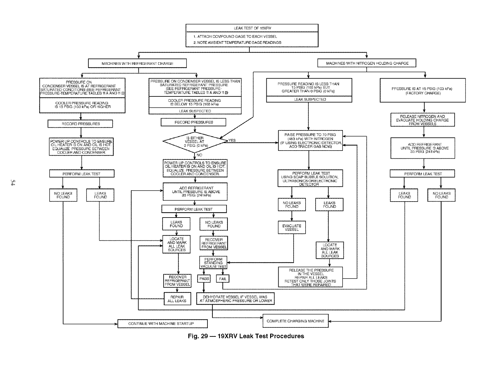
4_
LEAK TEST OF 19XRV
1, ATTACH COMPOUND GAGE TO EACH VESSEL
2. NOTE AMBLENT TEN_IPERATURE GAGE READINGS
I
MACHINES WITH REFRIGERANT CHARGE
1
PRESSURE ON
CONDENSERVESBELtS AT REFRIGERANT
SATURATED COND!TIONS SEE REFRIGERANT
PRESSURE*TEMPERATURETABLES 1AAND 1E
COOLER PRESSURE READING
S 15 PSIG (103 kPej OR HIGHER
I REDORDRRESSURESI
POWER UP CONTROLS TO ENSURE
OIL HEATER IS ON AND OIL IS HOT,
COOLER AND CONDENSER
EQUAUZE PRESSURE BE,,_,:_4EEN
1
I BERPORM_.EA_TESTI
[ FIoAK[_ l
PRESSURE ON CONDENSER VESSEL IS LESS THAN
SA/URA_ED REFRIGERAN F PRESSURE
(SEE REFRIGERANT PRESSURE-
TEMPERATURE TABLES 11A AND 1113)
COOLER PRESSURE READING
IS BELOW 15 PRIG (103 kP_,t)
LEAK SUSPECTED
1,
_,>,,'ss
POWER UP CONTROLS TO ENSURE
OIL HEATER IS ON AND OIL I9 HOT,
COOLER AND CONDENSER
EQUALIZE PRESSURE BETWEEN
½
:;I- ADD REFRIGERANT
UNTIL PRESSURE iS ABOVE
35 PSIG (241kP_)
{
I PBRFORMLEAK,SS,"1
I 1
FOUND
AND MARK
ALL LEAK
SOURCES
4,
I MAGHNESW,THN,TROGENROLD,NGDHARGEI
4,
PRESSURE READING IS LESS THAN
15 PSIG (103 kPei BUr
GREATER THAN 0 PSIG (0 kPa)
_AK SUSPEC ED
(IF USING ELECTRONIC DETECTOR, L
ADD TRACER GAS NOW) r'_
/
I PERFORM LEAK TEST I
USING SOAP BUBBLE SOLU]ION_
ULTRASONICS OR ELECTRONIC
DETECTOR
EVACUATB]
[ LODATEJ
AND MARK
ALL LEAK
SOURCES
ilcco,
STANDING ,1i:
RELEASE THE PRESSURE
IN THE VESSEL
REPAIR ALL LEAKS
RETEST ONLY THO_E JOtNTS
THAT WERE REPAIRED
REPAIR DEHYDRATE VESSEL IF VESSEL WAS
I
CONTINUE WITH MACHINE STARTUP / COMPLETE CHARGING MACHINE IIC
.I I
4,
PRBSSURE IS AT 15 PRIG (103 kP_,)
(FACTORY CHARGE)
RELEASE NITROGEN AND I
EVACUATE HOLDING CHARGE
FROM VESSELS
ADD REFRIGERANT 1
UNTIL PRESSURE S ABOVE
30 PSIG (241kPa)
I BERFORMLEA_TESTI
[ I
Fig. 29 -- 19XRV Leak Test Procedures
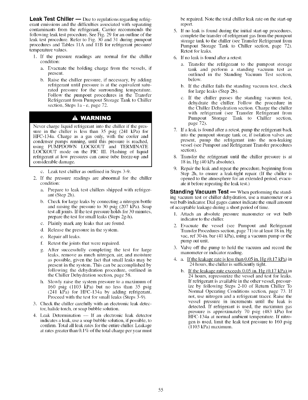
Leak Test Chiller -- Due to regulations regarding refiig-
erant emissions and the difficulties associated with separating
contaminants from the refrigerant, Carrier recommends the
following leak test procedure. See Fig. 29 for an outline of the
leak test procedure. Refer to Fig. 30 and 31 during pumpout
procedures and Tables 11A and 11B for refi'igerant pressure/
temperature values.
1. [f the pressure readings are normal for the chiller
condition:
a. Evacuate the holding charge fiom the vessels, if
present.
b. Raise the chiller pressure, if necessary, by adding
refrigerant until pressure is at the equivalent satu-
rated pressure for the surrounding temperature.
Follow the pumpout procedures in the Transfer
Refrigerant from Pumpout Storage Tank to Chiller
section, Steps I a - e, page 72.
Never charge liquid refrigerant into the chiller if the pres-
sure in the chiller is less than 35 psig (241 kPa) for
HFC-134a. Charge as a gas only, with the cooler and
condenser pumps running, until this pressure is reached,
using PUMPDOWN LOCKOUT and TERMINATE
LOCKOUT mode on the PIC III. Flashing of liquid
lefrigerant at low pressures can cause tube freeze-up and
considerable damage.
c. Leak test chiller as outlined in Steps 3-9.
2. If the pressure readings are abnormal for the chiller
condition:
a. Prepare to leak test chillers shipped with refriger-
ant (Step 2h).
b. Check for large leaks by connecting a nitrogen bottle
and raising the pressure to 30 psig (207 kPa). Soap
test all joints. If the test pressure holds for 30 minutes,
prepare the test for small leaks (Steps 2g-h).
c. Plainly mark any leaks that are found.
d. Release the pressure in the system.
e. Repair all leaks.
f. Retest the joints that were repaired.
g. After successfully completing the test for large
leaks, remove as much nitrogen, air. and moisture
as possible, given the fact that small leaks may be
present in the system. This can be accomplished by
following the dehydration procedure, outlined in
the Chiller Dehydration section, page 58.
h. Slowly raise the system pressure to a maximum of
160 psig (1103 kPa) but no less than 35 psig
(241 kPa) for HFC-134a by adding refrigerant.
Proceed with the test for small leaks (Steps 3-9).
3. Check the chiller carefully with an electronic leak detec-
tol: halide torch, or soap bubble solution.
4. Leak Determination --If an electronic leak detector
indicates a leak, use a soap bubble solution, if possible, to
confirm. Total all leak rates for the entire chillel: Leakage
at rates greater than 0.1% of the total charge per year must
be repaired. Note the toted chiller leak rate on the start-up
_eport.
5. If no leak is found during the initi_d start-up procedures,
complete the transfer of refrigerant gas from the pumpout
storage tank to the chiller (see Transfer Refiigerant from
Pumpout Storage Tank to Chiller section, page 72).
Retest for leaks.
6. If no leak is found after a retest:
a. Transfer the refrigerant to the pumpout storage
tank and perform a standing vacuum test as
outlined in the Standing Vacuum Test section,
below.
b. If the chiller fails the standing vacuum test, check
for large leaks (Step 2b).
c. If the chiller passes the standing vacuum test,
dehydrate the chiller. Follow the procedure in
the Chiller Dehydration section. Charge the chiller
with refrigerant (see Transfer Refrigerant fiom
Pumpout Storage Tank to Chiller section,
page 72).
7. If a leak is found after a retest, pump the refrigerant back
into the pumpout storage tank or, if isolation valves are
present, pump the refrigerant into the non-leaking
vessel (see Pumpout and Refrigerant Transfer procedures
section).
8. Transfer the refrigerant until the chiller pressure is at
18 in. Hg (40 kPa absolute).
9. Repair the leak and repeat the procedure, beginning from
Step 2h, to ensure a leak-tight repail: (If the chiller is
opened to the atmosphere for an extended period, evacu-
ate it before repeating the leak test.)
Standing Vacuum Test -- When perforlning the stand-
ing vacuum test or chiller dehydi'ation, use a manometer or a
wet bulb indicatol: Dial gages cannot indicate the small amount
of acceptable leakage during a short period of time.
1. Attach an absolute pressure manometer or wet bulb
indicator to the chillel:
2. Evacuate the vessel (see Pumpout and Refrigerant
Transfer Procedures section, page 71 ) to at least 18 in. Hg
vac, ref 30-in. bar (41 kPa), using a vacuum pump or the
pump out unit.
3. Valve off the pump to hold the vacuum and record the
manometer or indicator reading.
4. a. If the leakage rate is less than 0.05 in. Hg (0.17 kPa) in
24 hours, the chiller is sufficiently tight.
b. ffthe leakage rate exceeds 0.05 in. Hg (0.17 kPa) in
24 hours, repressurize the vessel and test for leaks.
If refrigerant is available in the other vessel, pressur-
ize by following Steps 2-10 of Return Chiller To
Normal Operating Conditions section, page 73. If
not, use nitrogen and a refi'igerant tracer Raise the
vessel plessure in increments until the leak is
detected. If refrigerant is used, the maximum gas
pressure is approximately 70 psig (483 kPa) for
HFC-134a at normal ambient temperature. If nitro-
gen is used, limit the leak test pressure to 160 psig
(1103 kPa) maximum.
55
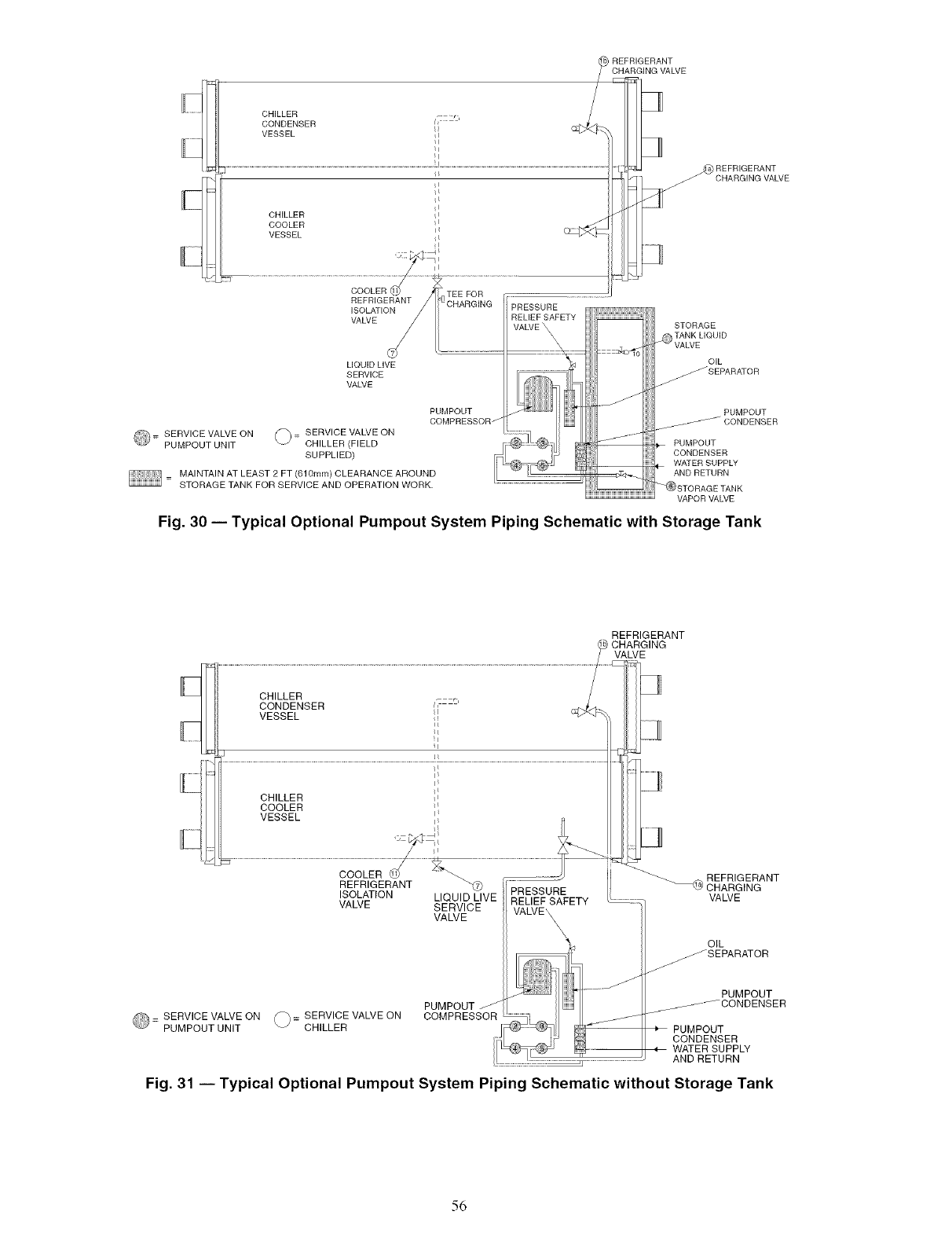
_) STORAGE TANK
VAPOR VALVE
Fig. 30 -- Typical Optional Pumpout System Piping Schematic with Storage Tank
REFRIGERANT
ISOLATION LIQUID LIVE
VALVE SERVICE
VALVE
PRESSURE
RELIEF SAFETY
VALVE_
REFRIGERANT
CHARGING
VALVE
REFRIGERANT
CHARGING
........ :: VALVE
OIL
= SERVICE VALVE ON 1_= SERVICE VALVE ON
PUMPOUT UNIT CHILLER
_SEPARATOR
....._ PUMPOUT
PUMPOUT _ _.//**./_*f CONDENSER
COMPRESSOR _] ___ i ....... "....
-_ PUMPOUT
I CONDENSER
q WATER SUPPLY
AND RETURN
Fig. 31 -- Typical Optional Pumpout System Piping Schematic without Storage Tank
56
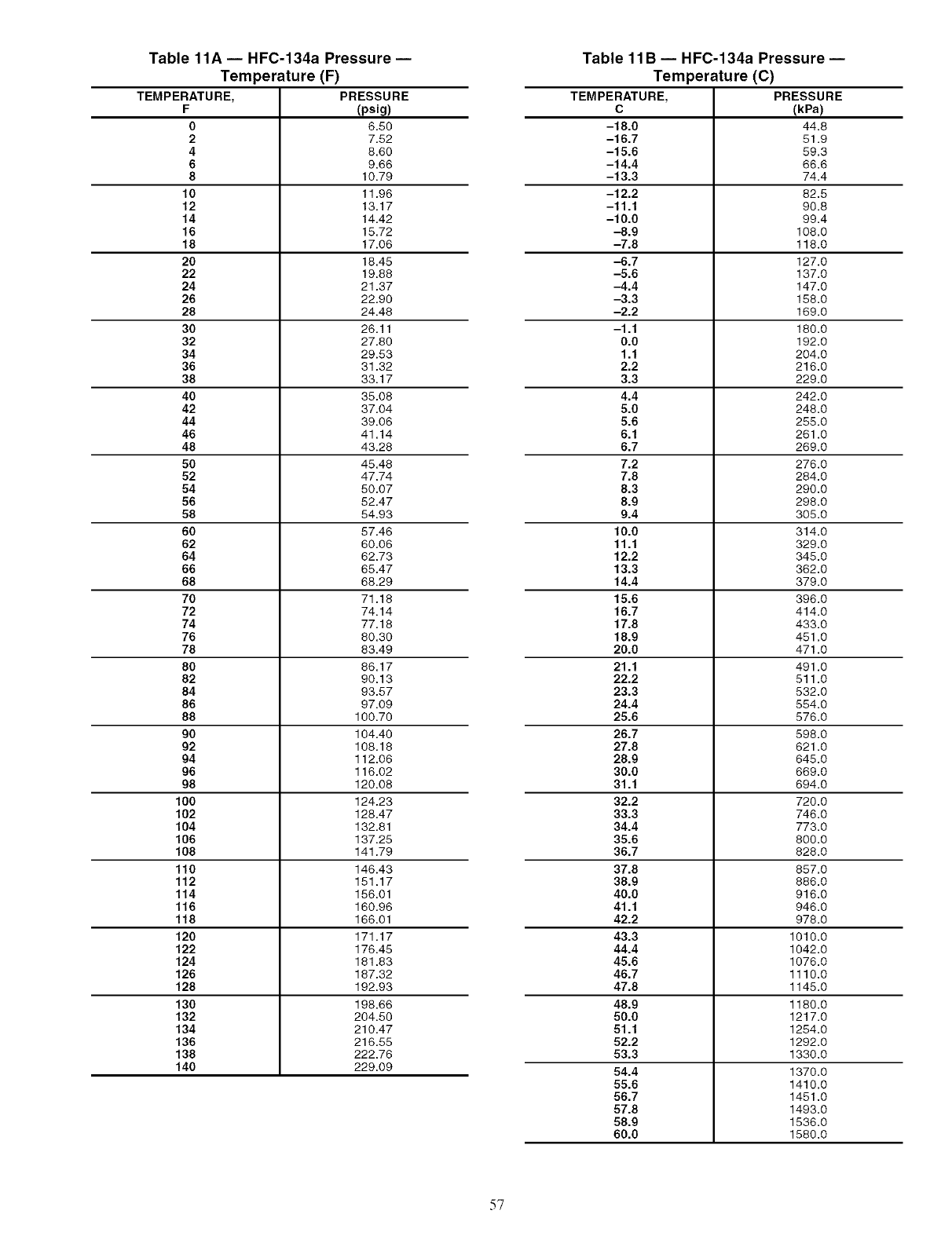
Table 11A- HFC-134a Pressure-
Temperature (F)
TEMPERATURE, PRESSURE
F (psig)
06.60
27.52
4 8.60
6 9.66
8 10.79
10 11.96
12 13.17
14 14.42
16 15.72
18 17.06
20 18.45
22 19.88
24 21.37
26 22.90
28 24.46
30 26.11
32 27.80
34 29.53
36 31.32
38 33.17
40 35.08
42 37.04
44 39.06
46 41.14
48 43.26
50 45.46
52 47.74
54 50.07
56 52.47
58 54.93
60 57.46
62 60.06
64 62.73
66 65.47
68 68.29
70 71.18
72 74.14
74 77.18
76 80.30
78 83.49
80 66.17
82 90.13
84 93.57
86 97.09
88 100.70
90 104.40
92 108.18
94 112.06
96 116.02
98 120.08
100 124.23
102 128.47
104 132.81
106 137.25
108 141.79
110 146.43
112 151.17
114 156.01
116 160.96
118 166.01
120 171.17
122 176.45
124 181.83
126 187.32
128 192.93
130 198.66
132 204.50
134 210.47
136 216.55
138 222.76
140 229.09
5?
Table 11B -- HFC-134a Pressure-
Temperature (C)
TEMPERATURE, PRESSURE
C (kPa)
-18.0 44.8
-16.7 51.9
-15.6 59.3
-14.4 66.6
-13.3 74.4
-12.2 82.5
-11.1 90.8
-10.0 99.4
-8.9 106.0
-7.8 118.0
-6.7 127.0
-5.6 137.0
-4.4 147.0
-3.3 158.0
-2.2 169.0
-1.1 180.0
0.0 192.0
1.1 204.0
2.2 216.0
3.3 229.0
4.4 242.0
5.0 248.0
5.6 255.0
6.1 261.0
6.7 269.0
7.2 276.0
7.8 284.0
8.3 290.0
8.9 298.0
9.4 305.0
10.0 314.0
11.1 329.0
12.2 345.0
13.3 362.0
14.4 379.0
15.6 396.0
16.7 414.0
17.8 433.0
18.9 451.0
20.0 471.0
21.1 491.0
22.2 511.0
23.3 532.0
24.4 554.0
25.6 576.0
26.7 598.0
27.8 621.0
28.9 645.0
30.0 669.0
31.1 694.0
32.2 720.0
33.3 746.0
34.4 773.0
35.6 800.0
36.7 826.0
37.8 657.0
38.9 886.0
40.0 916.0
41.1 946.0
42.2 978.0
43.3 1010.0
44.4 1042.0
45.6 1076.0
46.7 1110.0
47.8 1145.0
48.9 1180.0
50.0 1217.0
51.1 1254.0
52.2 1292.0
53.3 1330.0
54.4 1370.0
55.6 1410.0
56.7 1451.0
57.8 1493.0
58.9 1536.0
60.0 1580.0
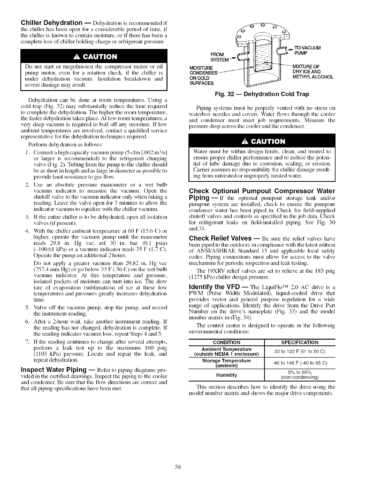
Chiller Dehydration -- Dehy&'ation is recommended if
the chiller has been open for a considerable period of time, if
the chiller is known to contain moisture, or if there has been a
complete loss of chiller holding chmge or refrigerant pressure.
Do not start o1 megohm-test the compressor motor or oil
pump motor, even for a rotation check, if tile chiller is
under dehydration vacuum. Insulation breakdown and
severe &tmage may result.
Dehydiation can be done at room temperatures. Using a
cold trap (Fig. 32) may substanti_dly reduce the time required
to complete the dehydration. The higher the room temperature,
the faster dehydration takes place. At low room temperatures, a
very deep vacuum is required to boil off any moisture. If low
ambient temperatures am involved, contact a qualified service
representative for the dehydration techniques required.
Perform dehydiation as follows:
1. Connect a high capacity vacuum pump (5 cfin [.002 m:Vsl
or Ireget is lecommended) to the refiigemnt chmging
v_dve (Fig. 2). Tubing from the pump to the chiller should
be as short in length and as large in diameter as possible to
provide least resistance to gas flow.
2. Use an absolute pressure manometer or a wet bulb
vacuum indicator to measure the vacuum. Open the
shutoff valve to the vacuum indicator only when taking a
reading. Leave the valve open for 3 minutes to allow the
indicator vacuum to equalize witi1 the chiller vacuum.
3. If the entire chiller is to be dehydiated, open all isolation
v_tives (if present).
4. With the chiller ambient temperature at 60 F (15.6 C) or
highel: operate tile vacuum pump until the manometer
roads 29.8 in. Hg vac, mf 30 in. bin: (0.1 psia)
(-100.61 kPa) or a vacuum indicator roads 35 F (1.7 C).
Operate the pump an additional 2 hours.
Do not apply a greater vacuum than 29.82 in. Hg vac
(757.4 mm Hg) or go below 33 F (.56 C) on the wet bulb
vacuum indicatol: At this temperature and pressure,
isolated pockets of moisture can turn into ice. The slow
rate of evaporation (sublimation) of ice at these low
temperatures and plessums greatly increases dehydi'ation
time.
5. Valve off tile vacuum pump, stop the pump, and record
the instrument reading.
6. After a 2-hour wait, take another instrument reading. If
the reading has not changed, dehydi'ation is complete. If
the reading indicates vacuum loss, repeat Steps 4 and 5.
7. If tile reading continues to change after several attempts,
perform a leak test up to the maximum 160 psig
(1103 kPa) pressure. Ix)cate and lepair the leak, and
repeat dehydration.
Inspect Water Piping -- Refer to piping diagrams pro-
vided in the certified di'awings. [nspect the piping to the cooler
and condense1: Be sum that the flow directions am conect and
that all piping specifications have been met.
_...,. TO VACUUM
FROM IIL:--;:L4 PUMP
S¥STEM-' I
_A_l_'n Im_ -.4IP- _]1 _ MIXTURE OF
_I_I_E_ENS_ES_ _ DRYICEAND
ON COLD METHYL ALCOHOL
SURFACES
Fig. 32 -- Dehydration Cold Trap
Piping systems must be properly vented with no stress on
waterbox nozzles and covel.s. Water flows through the cooler
and condenser must meet job requirements. Measure the
pressure drop across tile cooler and the condenser
Water must be within design limits, clean, and treated to
ensure proper chiller perfommnce and to reduce the poten-
tial of tube &tmage due to corrosion, scaling, or erosion.
Carrier assumes no responsibility for chiller damage result-
ing from unUeated or improperly treated watel:
Check Optional Pumpout Compressor Water
Piping- If the optkmal pumpout storage tank and/or
pmnpout system _u'e installed, check to ensure the pmnpout
condenser water has been piped in. Check for field-supplied
shutoff valves and controls as specified in the job data. Check
for refrigerant leaks on field-inst_dled piping. See Fig. 30
and 31.
Check Relief Valves -- Be sure the relief valves have
been piped to the outdoors in compliance with tile latest edition
of ANSI/ASHRAE Standard 15 and applicable local safety
codes. Piping connections must allow for access to the v_tive
mechanism for periodic inspection and leak testing.
The 19XRV relief valves are set to relieve at the 185 psig
(1275 kPa) chiller design pressure.
Identify the VFD -- Tile LiquiFlo TM 2.0 AC di'ive is a
PWM (Pulse Width Modulated), liquid-cooled drive that
provides vector and general purpose regulation for a wide
range of applications. Identify the drive from the Drive Pall
Number on the drive's nameplate (Fig. 33) and the model
number matrix in (Fig. 34).
The control center is designed to operate in the following
environmental conditions:
CONDITION SPECIFICATION
Ambient Temperature
(outside NEMA 1 enclosure) 32 to 122 F (0° to 50 C)
Storage Temperature
(ambient) -40 to 149 F (-40 to 65 C)
5% to 95%
Humidity (non-condensing)
This section describes how to identify tile drive using the
model number matrix and shows the major drive components.
58
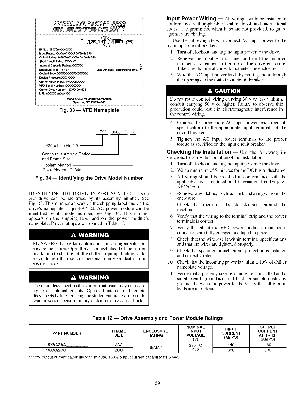
12=ncm@[j n_
ID NO.: 18O7(X)-X)(X-XXX
Input Rating: XXXVAC X)O(A 50/60Hz 3PH
Oulput Rating: 0-48OVAC X)O(A 0-400Hz 3PH
Short Circuit Rating: XXXXXX
Interrupt Capacity Ragng: )OOOO¢,X
Enclosure Type: TYPE 1
Coolant Type: _
Design Pressure: X)O( X)O(X
Carder Part Number: 19XRA2X)O(XX
VFD Sedal Number. XXXXXX_OO(
Carrier Dwg. Number: 19XV04004501
Mfd. InXX)O(on XJoc)O(
Made In USA for Carder Colporagon,
Syracuse. NY 13221-4808.
Fig. 33 -- VFD Nameplate
Max. Ambient Temperature: 50°C
LF20 = LiquiFIo 2.0
Continuous Ampere Rating
and Frame Size
Coolant Method
R = refrigerant R134a
LF20 0608CC R
Fig. 34 -- Identifying the Drive Model Number
IDENTIFYING THE DRIVE BY PART NUMBER -- Each
AC drive can be identified by its assembly number. See
Fig. 33. This number appears on the shipping label and on the
drive's nameplate. LiquiFlo TM 2.0 AC power module can be
identified by its model number See Fig. 34. This number
appears on the shipping htbel and on the power module's
nameplate. Power ratings are provided in Table 12.
BE AWARE that certtfin automatic start arrangements can
engage the startel: Open the disconnect ahead of the starter
in addition to shutting off the chiller or pump. Failure to do
so could result in serious personal inju Uor death from
electric shock.
The mtfin disconnect on the starter fiont panel may not deen-
ergize all internal circuits. Open all internal and lemote
disconnects before servicing the st_uter Failure to do so could
lesult in serious peLson_d injmy or death from electric shock.
Input Power Wiring -- All wiring should be installed in
conformance with applicable local, national, and international
codes. Use grommets, when hubs are not provided, to guard
against wire chafing.
Use the following steps to connect AC input power to the
main input circuit breaker:
1. Turn off. lockout, and tag the input power to the diive.
2. Remove the input wiring panel and drill the required
number of openings in the top of the drive enclosure.
Take care that metal chips do not enter the enclosure.
3. Wire the AC input power leads by routing them through
the openings to the main input circuit breakel:
Do not route control wiring carrying 30 v or less within a
conduit carrying 50 v or highel: Failure to observe this
precaution could result in electromagnetic interference in
the control wiring.
4. Connect the three-phase AC input power leads (per job
specification) to the appropriate input terminals of the
circuit breaker
5. Tighten the AC input power terminals to the proper
torque as specified on the input circuit breakel:
Checking the Installation -- Use the following in-
structions to verify the condition of the instalhttion:
1. Turn off. lockout, and tag the input power to the diive.
2. Wait a minimum of 5 minutes for the DC bus to dischtuge.
3. All wiring should be installed in conformance with the
applicable local, national, and international codes (e.g.,
NEC/CEC).
4. Remove any debris, such as metal shavings, from the
enclosure.
5. Check that there is adequate cle_u'ance around the
machine.
6. Verify that the wiring to the terminal strip and the power
terminals is coned.
7. Verify that all of the VFD power module circuit bo_ud
connectors are fully engaged and taped in phtce.
8. Check that the wire size is within terminal specifications
and that the wiles me tightened properly.
9. Check that specified branch circuit protection is installed
and conectly rated.
10. Check that the incoming power is within _+10% of chiller
nameplate voltage.
11. Verify that a properly sized ground wile is installed and a
suitable emlh ground is used. Check for and eliminate any
grounds between the power leads. Verify that all ground
leads are unbroken.
Table 12 -- Drive Assembly and Power Module Ratings
OUTPUT
NOMINAL INPUT CURRENT
INPUT CURRENT
VOLTAGE AT 4 kHz*
(V) (AMPS) (AMPS)
380 TO 440 460
460 608 608
PARTNUMBER FRAME ENCLOSURE
SIZE RATING
19XVA2AA 2AA NEMA1
19XVA2CC 2CC
*110% outputcurrentcapabilityforl minute. 150% outputcurrentcapability _r5sec.
59
Inspect Wiring
Do not check the voltage supply without proper equipment
and precautions. Sedous personal injury may result. Follow
power company recommen&ttions.
Ground Fault Troubleshooting -- Follow this pro-
cedure only if ground faults are declared by tile chiller controls.
Test the chiller compressor motor and its power lead
insulation resistance with a 500-v insukition tester such as a
megohlnmetec
a. Open the starter main disconnect switch and follow
lockout/tagout rules.
Do not apply any kind of test voltage, even for a rotation
check, if the chiller is under a dehydration vacuum. Insula-
tion breakdown and serious &image may result.
1. Examine the wiring for conformance to the job wiring
diagrmns and all applicable electrical codes.
2. Connect a voltmeter across the power wires to the VFD
and measure the phase to phase and phase to ground
voltage. Compare this reading to the voltage rating on the
compressor and st_uter nameplates.
3. Compare the ampere rating on the VFD enclosure
nmneplate to the rating on the compressor nameplate.
OVERLOAD TRIP AMPS must be 108% of the
MOTOR RATED LOAD AMPS.
4. The control center must be wired to components and
terminals required for PIC III refrigeration control. Check
line side power and for control components shown on the
Cellified Prints. The control center must share control of
cooler and condenser liquid pumps and cooling tower
fans.
5. Check the phase to phase and phase to ground line
voltage to the control center and the optional pumpout
compressoc Compare voltages against nameplate values.
6. Ensure that fused disconnects or circuit breakers have
been supplied to the control center and optional pumpout
unit.
7. Ensure all electrical equipment and controls are properly
grounded in accordance with the job di'awings, certified
drawings, and all applicable electrical codes.
8. Ensure the customer's contractor has verified proper oper-
ation of the pumps, cooling tower fans, and associated
auxiliary equipment. This includes ensuring motors are
properly lubricated and have proper electric_d supply and
proper rotation.
9. Tighten _dl wiring connections on the high and low
voltage termimd blocks in the control center enclosure
below the control panel.
10. Inspect the control panel in file control center enclosure to
ensure that the contractor has used the knockouts to feed
the wires into the back of the control panel. Wiring into
the top of the panel can cause debris to fall into the
control centel: Clean and inspect the interior of the
control center if this has occurred.
Do not apply power unless a qualified Carrier technician is
present. Serious personal injuUmay result.
11. Apply power to the control center. Go to the ICVC and
access the MENU>SERVICE>VFD CONFIG
DATA>VFD_CONF screen. Confirm that the parame-
ters entered in VFD_CONF match the information on
the Machine Nameplate and Sales Requisition. Con-
firm that the serial numbers on the chiller, Machine
Nameplate, and Sales Requisition are consistent.
The motor leads must be disconnected from the VFD
before an insulation test is performed. The voltage
generated from the tester can damage the starter solid-state
components in the VFD.
b. With the tester connected to the motor leads, take
10-second and 60-second megohm readings as
follows:
Tie terminals 1, 2, and 3 together and test between
the group and ground.
c. Divide the 60-second resistance reading by the
10-second reading. The ratio, or polarization
index, must be one or higher. Both the 10 and
60-second readings must be at least 50 megohms.
If the readings are unsatisfactory, repeat the test at
the motor with the power leads disconnected.
Satisfactory readings in this second test indicate
the fault is in the power leads.
Carrier Comfort Network Interface -- Tile C_urier
Colnfol-t Network (CCN) connnunication bus wiring is
supplied and inst_dled by the electrical contractol: It consists of
shielded, 3-conductor cable with di'ain wire.
The system elements are connected to the communication
bus in a daisy chgdn m'rangement. The positive pin of each
system element communication connector must be wired to the
positive pins of the system element on either side of it. Tile
negative pins must be wired to the negative pins. The signal
ground pins must be wired to file signal ground pins. See
installation manual.
NOTE: Conductors and drain wire must be 20 AWG
(American Wire Gage) minimum stranded, tinned coppel:
Individual conductors must be insulated with PVC, PVC/
nylon, vinyl, Teflon, or polyethylene. An aluminum/polyester
100% foil shield and an outer jacket of PVC, PVC/nylon,
chrome vinyl, or Teflon with a minimum operating tempera-
ture range of -4 F to 140 F (-9-0 C to 60 C) is required. See
table below for cables flint meet the requirements.
MANUFACTURER CABLE NO.
Alpha 2413 or 5463
American A22503
Belden 8772
Columbia 02525
When connecting tile CCN communication bus to a system
element, a color code system for the entire network is recom-
mended to simplify installation and checkout. The following
color code is recommended:
CCN BUS CCN ICVC PLUG J1
SIGNAL CONDUCTOR TERMINAL PIN NO.
TYPE INSULATION CONNECTION
COLOR
+ Red RED (+) 1
Ground White WHITE (G) 2
Black BLACK (-) 3
6O
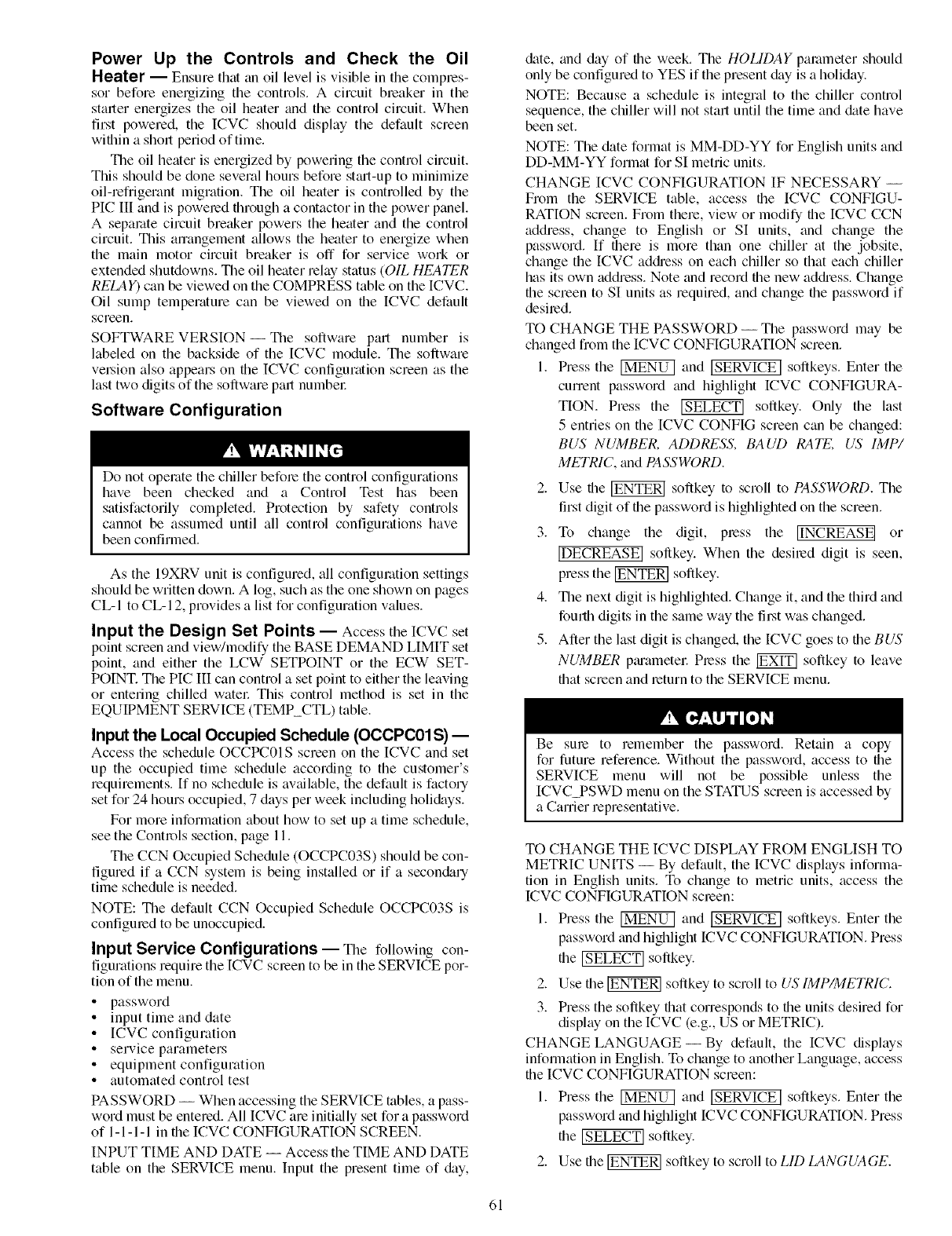
Power Up the Controls and Check the Oil
Heater -- Ensure that an oil level is visible in the compres-
sor before energizing the controls. A circuit bleaker in the
starter energizes the oil heater and the control circuit. When
first powered, the ICVC should display the default screen
within a short period of time.
Tile oil heater is energized by powering the control circuit.
This should be done several hours before sta-t-up to minimize
oil-refiigerant migration. The oil heater is controlled by the
PIC Ill and is poweled through a contactor in the power panel.
A separate circuit breaker powers the heater and the control
circuit. This ammgement allows the heater to energize when
the main motor circuit breaker is off for service work or
extended shutdowns. Tile oil heater relax/status (OIL HEATER
RELAY) can be viewed on the COMPRI_SS table on the ICVC.
Oil sump temperature can be viewed on the ICVC default
screen.
SOFTWARE VERSION- The software part number is
labeled on the backside of the [CVC module, The software
velMon also appears on the ICVC configuration screen as the
last two digits of the software part numbel:
Software Configuration
Do not operate the chiller befole the control configuraions
have been checked and a Control Test has been
satisfactorily completed. Protection by safety controls
cannot be assumed until all control configurations have
been confirmed.
As the 19XRV unit is configured, all configuration settings
should be written down. A log, such as the one shown on pages
CL-I to CL-I 2, provides a list for configuration values.
Input the Design Set Points -- Access the ICVC set
point screen and view/modify the BASE DEMAND LIMIT set
point, and either the LCW SETPOINT or the ECW SET-
POINT. The PIC III can control a set point to either the leaving
or entering chilled water This control method is set in the
EQUIPMENT SERVICE (TEMP_CTL) table.
Input the Local Occupied Schedule (OCCPC01S) --
Access the schedule OCCPC01S screen on the ICVC and set
up the occupied time schedule according to the customer's
requirements. If no schedule is available, the default is factory
set for 24 hours occupied, 7 days per week including holi&tys.
For more information about how to set up a time schedule,
see the Controls section, page 11.
The CCN Occupied Schedule (OCCPC03S) should be con-
figured if a CCN system is being installed or if a secon&try
time schedule is needed.
NOTE: The default CCN Occupied Schedule OCCPC03S is
configmed to be unoccupied.
Input Service Configurations -- Ti_e following con-
figurations require the ICVC scleen to be in the SERVICE por-
tion of the menu.
• password
• input time and date
• ICVC configuration
• service parameters
• equipment configuration
• automated control test
PASSWORD -- When accessing the SERVICE tables, a pass-
word must be entered. All ICVC are initially set for a password
of 1- 1- 1- 1 in the ICVC CONFIGURATION SCREEN.
INPUT TIME AND DATE -- Access the TIME AND DATE
table on the SERVICE menu. Input the present time of chy,
date, and day of the week. The HOLIDAY parameter should
only be configured to YES if the present &ty is a holiday.
NOTE: Because a schedule is integral to the chiller control
sequence, the chiller will not start until the time and &tte have
been set.
NOTE: The date format is MM-DD-YY for English units and
DD-MM-YY format for SI metric units.
CHANGE ICVC CONFIGURATION IF NECESSARY --
From the SERVICE table, access the ICVC CONFIGU-
RATION screen. From there, view or modify the ICVC CCN
address, change to English or SI units, and change the
password. If fllere is more than one chiller at the jobsite,
change the ICVC addiess on each chiller so that each chiller
has its own address. Note and record the new addiess. Change
the screen to SI units as required, and change the password if
desiled.
TO CHANGE THE PASSWORD -- The password may be
changed from the ICVC CONFIGURATION screen.
1. Press the _ and [SERVICE] softkeys. Enter the
current password and highlight ICVC CONFIGURA-
TION. Press the _ softkey. Only the last
5 entries on the ICVC CONFIG screen c_m be changed:
BUS NUMBER, ADDRESS, BAUD RATE, US IMP/
METRIC, and PASSWORD.
2. Use file _ softkey to scroll to PASSWORD. The
first digit of file password is highlighted on the screen.
3. To change the digit, press the IINCREASE] or
[DECREASE] soflkey. When the desired digit is seen,
press the _ softkey.
4. The next digit is highlighted. Change it, and the third and
fourth digits in the same way the lil.st was changed.
5. After the last digit is changed, the ICVC goes to file BUS
NUMBER pmametel: Press the _ softkey to leave
that screen and leturn to the SERVICE menu.
Be sure to remember the password. Retain a copy
for future reference. Without the password, access to the
SERVICE menu will not be possible unless the
ICVC PSWD menu on the STATUS screen is accessed by
a Carrier representative.
TO CHANGE THE ICVC DISPLAY FROM ENGLISH TO
METRIC UNITS --By default, the ICVC displays informa-
tion in English units. To change to metric units, access the
ICVC CONFIGURATION scleen:
1. Press the _ and [SERVICE] softkeys. Enter the
password and highlight ICVC CONFIGURATION. Press
the _ softkey.
2. Use file _ softkey to scroll to US IMP/METRIC.
3. Press the softkey flint conesponds to file units desired for
display on the ICVC (e.g., US or METRIC).
CHANGE LANGUAGE--By default, the ICVC displays
information in English. To change to another Language, access
the ICVC CONFIGURATION screen:
1. Press the _ and [SERVICE[ softkeys. Enter the
password and highlight ICVC CONFIGURATION. Press
the _ softkey.
2. Use the _ softkey to scroll to LID LANGUAGE.
61
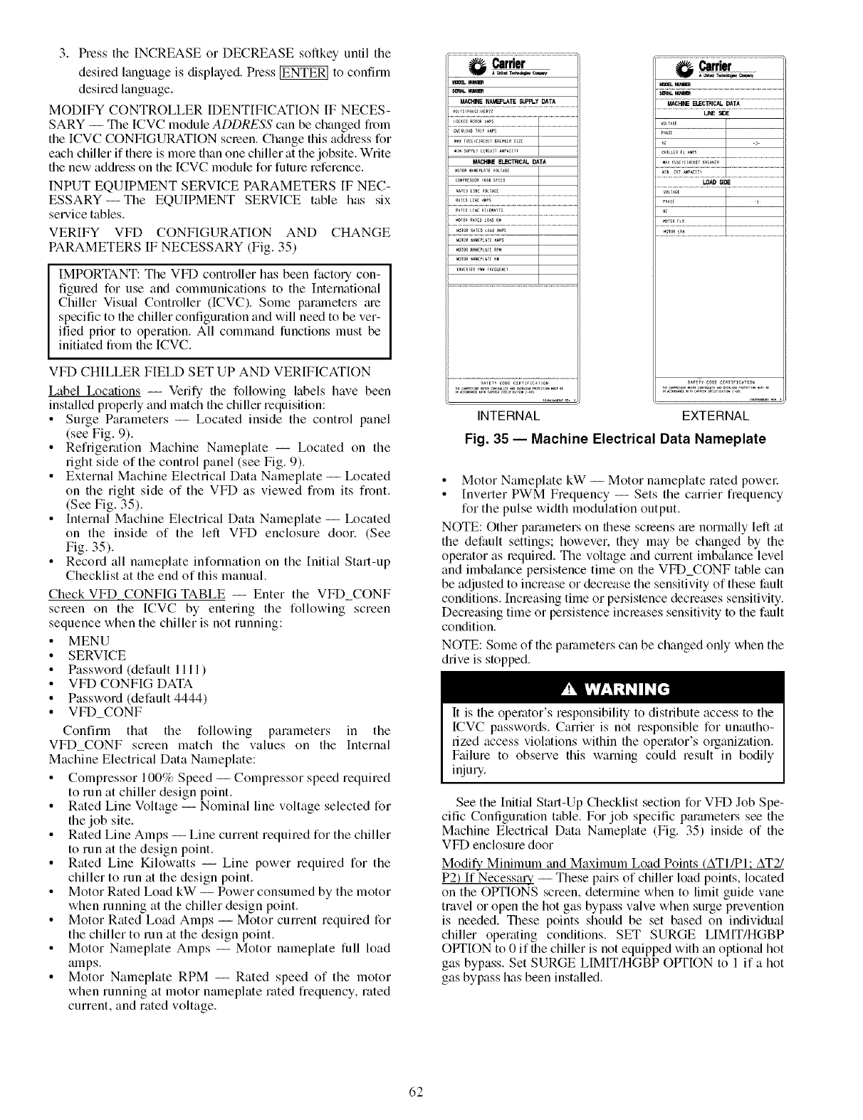
3. PresstheINCREASEorDECREASEsoftkeyuntilthe
desiredlanguageisdisplayed.Press_ toconfirm
desiredlanguage.
MODIFYCONTROLLERIDENTIFICATIONIFNECES-
SARY-- TheICVCmoduleADDRESS can be changed from
the ICVC CONFIGURATION screen. Change this adc_hess for
each chiller if there is more than one chiller at the jobsite. Write
the new adc_hess on the [CVC module for future reference.
INPUT EQUIPMENT SERVICE PARAMETERS IF NEC-
ESSARYiThe EQUIPMENT SERVICE table has six
service tables.
VERIFY VFD CONFIGURATION AND CHANGE
PARAMETERS IF NECESSARY (Fig. 35)
IMPORTANT: The VFD controller has been factory con-
figured for use and communications to the International
Chiller Visual Controller (ICVC). Some parmneters ;ue
specific to the chiller configuration and will need to be ver-
ified prior to operation. All command functions must be
initiated from the [CVC.
VFD CHILLER FIELD SET UP AND VERIFICATION
Label Ix_cations -- Verify the following labels have been
installed properly and match the chiller requisition:
• Surge Parameters -- Located inside the control panel
(see Fig. 9).
• Refrigeration Machine Nameplate -- Located on the
right side of the control panel (see Fig. 9).
• External Machine Electrical Data Nameplate -- Ix_cated
on the right side of the VFD as viewed from its front.
(See Fig. 35).
• Internal Machine Electrical Data Nameplate -- Ix_cated
on the inside of the left VFD enclosure door. (See
Fig. 35).
• Record all nameplate information on the Initial Start-up
Checklist at the end of this manual.
Check VFD CONFIG TABLE -- Enter the VFD_CONF
screen on the [CVC by entering the following screen
sequence when the chiller is not running:
• MENU
• SERVICE
• Password (default 1111)
• VFD CONFIG DATA
• Password (default 4444)
• VFD_CONF
Confirm that the following parameters in the
VFD_CONF screen match the values on the Internal
Machine Electrical Data Nameplate:
•Compressor 100% Speed -- Compressor speed required
to run at chiller design point.
• Rated Line Voltage -- Nominal line voltage selected for
the job site.
• Rated Line Amps -- Line current required for the chiller
to run at the design point.
• Rated Line Kilowatts -- Line power required for the
chiller to run at the design point.
• Motor Rated Load kW -- Power consumed by the motor
when running at the chiller design point.
• Motor Rated Load Amps -- Motor current required for
the chiller to run at the design point.
• Motor Nameplate Amps -- Motor nameplate full load
amps.
• Motor Nameplate RPM -- Rated speed of the motor
when running at motor nameplate rated frequency, rated
current, and rated voltage.
Mmq
uB
MACHINE NAMEPLATE $_FI.Y DATA
M_ r_Cl_CUsT _R_A_ER_ZE I
MACHINEELECINCAL DATA
_*o_ N_M PLAXE VO AG_
Carrier
MACH_ ELEC_ICAL DATA
u_ SIDE
10AD SIDE
INTERNAL
Fig. 35 -- Machino Electrical Data Namoplato
sA,,,, COOEce_I,I_,,o,
EXTERNAL
• Motor Nameplate kW iMotor nameplate rated power:
• Inverter PWM Frequency -- Sets the carrier frequency
for the pulse width modulation output.
NOTE: Other pm'ameters on these screens me normally left at
the default settings; however, they may be changed by the
operator as _equired. The voltage and current imbalance level
and imbalance persistence time on the VFD_CONF table can
be adjusted to increase or decrease the sensitivity of these fault
conditions. Increasing time or pe_.sistence decreases sensitivity.
Decreasing time or persistence increases sensitivity to the fault
condition.
NOTE: Some of the parameters can be changed only when the
drive is stopped.
It is the operator's responsibility to distribute access to the
ICVC passwords. Carrier is not responsible for unautho-
rized access violations within the operator's organization.
Failure to observe this warning could result in bodily
injury.
See the Initial Start-Up Checklist section for VFD Job Spe-
cific Configuration table. For job specific pm'ameters see the
Machine Electrical Data Nameplate (Fig. 35) inside of the
VFD enclosure door
Modify Minimum and Maximum Load Points (ATI/PI: AT2/
P2) If-NecessaLy -- These pairs of chiller load points, located
on the OPTIONS screen, determine when to limit guide vane
travel or open the hot gas bypass valve when surge prevention
is needed. These points should be set based on individual
chiller operating conditions. SET SURGE LIMIT/HGBP
OPTION to 0 if the chiller is not equipped with an optional hot
gas bypass. Set SURGE LIMIT/HGBP OPTION to 1 if a hot
gas bypass has been installed.
62
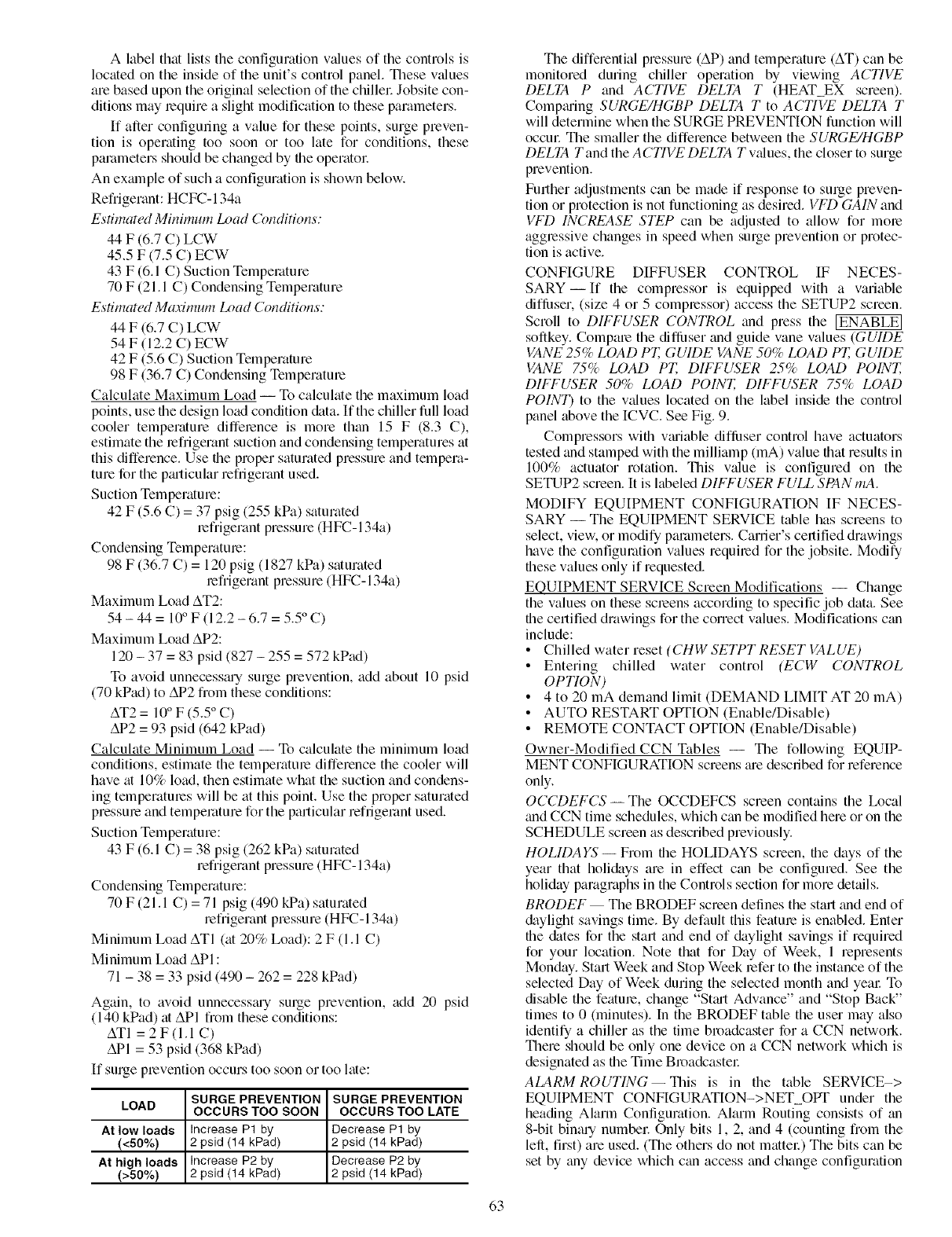
A labelthatliststheconfigurationv_duesofthecontrolsis
locatedontheinsideoftheunit'scontrolpanel.Thesev_dues
arebasedupontheoriginalselectionofthechillel:Jobsitecon-
ditionsmayrequireaslightmodificationtotheseparameters.
If afterconfiguringavalueforthesepoints,surgepreven-
tionis operatingtoosoonor toolatefor conditions,these
parametersshouldbechangedbyfileoperatol:
Anexmnpleofsuchaconfigurationisshownbelow.
Refrigerant:HCFC-134a
Estimated Minimum Load Conditions:
44 F (6.7 C) LCW
45.5 F (7.5 C) ECW
43 F (6.1 C) Suction Temperature
70 F (21.1 C) Condensing Temperature
Estimated Maaimum Load Conditions:
44 F (6.7 C) LCW
54 F (12.2 C) ECW
42 F (5.6 C) Suction Temperature
98 F (36.7 C) Condensing Temperature
Calculate Maximum Load -- To calculate the maximum load
points, use file design load condition <a. If the chiller full load
cooler temperature difference is more than 15 F (8.3 C),
estimate the refrigerant suction and condensing temperatures at
this difference. Use file proper saturated pressure and tempera-
ture for the pmticular refrigerant used.
Suction Temperature:
42 F (5.6 C) = 37 psig (255 kPa) saturated
refrigerant pressure (HFC- 134a)
Condensing Temperature:
98 F (36.7 C) = 120 psig (1827 kPa) saturated
refrigerant pressure (HFC- 134a)
Maximum Load AT2:
54 - 44 = 10° F (12.2 - 6.7 = 5.5 ° C)
Maximum Load AP2:
120 - 37 = 83 psid (827 - 255 = 572 kPad)
To avoid unnecessmy surge prevention, add about 10 psid
(70 kPad) to AP2 from these conditions:
AT2 = 10° F (5.5 ° C)
AP2 = 93 psid (642 kPad)
Calculate Minimum Load -- To calculate the minimum load
conditions, estimate the temperature difference the cooler will
have at 10% load, then estimate what the suction and condens-
ing temperatures will be at this point. Use the proper saturated
pressure and temperature for the particular refrigerant used.
Suction Temperature:
43 F (6.1 C) = 38 psig (262 kPa) saturated
refrigerant pressure (HFC- 134a)
Condensing Temperature:
70 F (21.1 C) = 71 psig (490 kPa) saturated
refrigerant pressure (HFC-134a)
Minimum Load ATI (at 20% Load): 2 F (1.1 C)
Minimum Load API :
71 - 38 = 33 psid (490 - 262 = 228 kPad)
Again, to avoid unnecesstuy surge prevention, add 20 psid
(140 kPad) at API from these conditions:
ATI = 2F(I.I C)
API = 53 psid (368 kPad)
If surge prevention occurs too soon or too late:
SURGE PREVENTION SURGE PREVENTION
LOAD OCCURS TOO SOON OCCURS TOO LATE
At low loads Increase Pl by Decrease P1 by
(<50%) 2 psid (14 kPad) 2 psid (14 kPad)
At high loads Increase P2 by Decrease P2 by
(>50%) 2 psid (14 kPad) 2 psid (14 kPad)
The differential pressure (AP) and temperature (AT) can be
monitored during chiller operation by viewing ACTI1/E
DELTA P and ACTIVE DELTA T (HEAT EX screen).
Compming SURGE/HGBP DELTA T to ACTIVE DELTA T
will determine when the SURGE PREVENTION function will
occur The smaller the difference between the SURGE/HGBP
DELTA T and the A CTI1/E DELTA T v_flues, the closer to surge
prevention.
Further adjustments can be made if response to surge preven-
tion or protection is not functioning as desired. VFD GAIN and
I/FD INCREASE STEP can be adjusted to allow for more
agglessive changes in speed when surge prevention or protec-
tion is active.
CONFIGURE DIFFUSER CONTROL IF NECES-
SARY- If the compressor is equipped with a variable
diflhser, (size 4 or 5 complessor) access the SETUP2 screen.
Scroll to DIFFUSER CONTROL and press the IENABLE]
softkey. Compare the diflhser and guide vane values (GUIDE
VANE 25% LOAD PT, GUIDE VANE 50% LOAD PT, GUIDE
VANE 75% LOAD PT, DIFFUSER 25% LOAD POINT,
DIFFUSER 50% LOAD POINT, DIFFUSER 7.5% LOAD
POINT) to the values located on the label inside the control
panel above the ICVC. See Fig. 9.
Compressors wifll vmiable diflhser control have actuators
tested and stamped with the milliamp (mA) value that results in
100% actuator rotation. This v¢flue is configured on the
SETUP2 screen. It is labeled DIFFUSER FULL SPAN mA.
MODIFY EQUIPMENT CONFIGURATION IF NECES-
SARY -- The EQUIPMENT SERVICE table has screens to
select, view, or modify parameters. Career's certified drawings
have the configuration values required for the jobsite. Modify
fllese values only if requested.
EQUIPMENT SERVICE Screen Modifications -- Change
the values on these screens according to specific job data. See
file certified drawings for the correct values. Modifications can
include:
•Chilled water reset (CHW SETPT RESET VALUE)
• Entering chilled water control (ECW CONTROL
OPTION)
• 4 to 20 mA demand limit (DEMAND LIMIT AT 20 mA)
• AUTO RESTART OPTION (Enable/Disable)
• REMOTE CONTACT OPTION (Enable/Disable)
Owner-Modified CCN Tables -- The following EQUIP-
MENT CONFIGURATION screens me described for reference
only.
OCCDEFCS- The OCCDEFCS screen contains the Ix_cal
trod CCN time schedules, which can be modified here or on the
SCHEDULE screen as described previously.
HOLIDAYS -- From file HOLIDAYS screen, file days of the
year that holidays are in effect can be configured. See the
holiday paragraphs in the Controls section for more details.
BRODEF The BRODEF screen defines the start trod end of
&tylight savings time. By default this feature is enabled. Enter
file (kites for the start and end of daylight savings if required
for your location. Note that for Day of Week, 1 represents
Monday. Start Week and Stop Week refer to the instance of the
selected Day of Week during the selected month and yem: To
disable the feature, change "Stml Advance" and "Stop Back"
times to 0 (minutes). In the BRODEF table the user may also
identify a chiller as the time broadcaster for a CCN netwoN.
There should be only one device on a CCN network which is
designated as the Time Broadcastel:
ALARM ROUTING--This is in the table SERVICE->
EQUIPMENT CONFIGURATION->NET OPT under the
heading Alarm Configuration. Alarm Routing consists of tin
8-bit binary number Only bits 1, 2, and 4 (counting from the
left, first) are used. (The others do not mattel:) The bits can be
set by tiny device which can access and change configuration
63
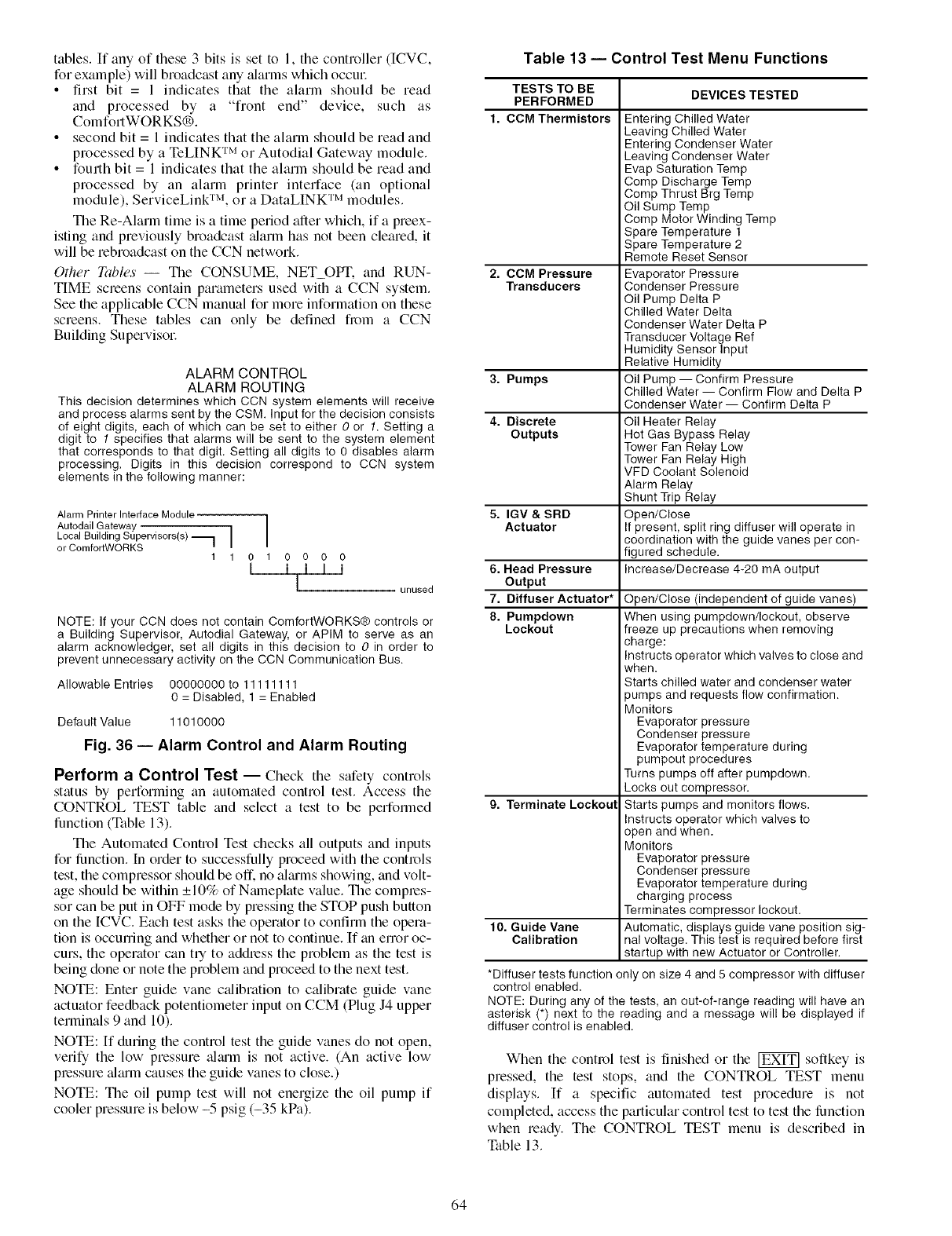
tables.If anyofthese3bitsissetto1,thecontroller(ICVC,
forexample)willbroadcastany;darmswhichoccm:
• first bit = 1 indicatesthatthealarmshouldberead
and processedby a "front end" device,suchas
ComfortWORKS®.
• second bit = 1 indicates that the alarm should be read and
processed by a TeLINK TM or Autodial Gateway module.
• fourth bit = 1 indicates that the alarm should be read and
processed by an alarm printer interface (an optional
module), ServiceLink TM, or a DataLINK TM modules.
The Re-Alarm time is a time period after which, if a preex-
isting and previously broadcast ;darm has not been cleared, it
will be rebroadcast on the CCN network.
Other _ibles -- The CONSUME, NET_OPT. and RUN-
TIME screens contain parameters used with a CCN system.
See the applicable CCN manual for more information on these
screens. These tables can only be defined from a CCN
Building Supervisol:
ALARM CONTROL
ALARM ROUTING
This decision determines which CCN system elements will receive
and process alarms sent by the CSM. Input for the decision consists
of eight digits, each of which can be set to either 0or 1. Setting a
digit to 1specifies that alarms will be sent to the system element
that corresponds to that digit. Setting all digits to 0 disables alarm
processing. Digits in this decision correspond to CCN system
elements in the following manner:
Alarm Printer Interface Module 1
Autodail Gateway /
Local Building Supervisors(s) _ I
or ComfortWORKS I
11010
I000
I I I l
Iunused
NOTE: If your CCN does not contain ComfortWORKS® controls or
a Building Supervisor, Autodial Gateway, or APIM to serve as an
alarm acknowledger, set all digits in this decision to 0in order to
prevent unnecessary activity on the CCN Communication Bus.
Allowable Entries 00000000 to 11111111
0 = Disabled, 1 = Enabled
Default Value 11010000
Fig. 36 -- Alarm Control and Alarm Routing
Perform a Control Test -- Check the safety controls
status by performing an automated control test. Access the
CONTROL TEST table and select a test to be performed
function (Table 13).
The Automated Control Test checks all outputs and inputs
for lunction. In order to successfully proceed with the controls
test, the compressor should be off. no aimms showing, and volt-
age should be within _+10% of Nmneplate value. The comples-
sot can be put in OFF mode by pressing the STOP push button
on the [CVC. Each test asks the operator to confirm the opera-
tion is occurring and whether or not to continue. If an error oc-
curs, the operator can try to addless the problem as the test is
being done or note the problem and proceed to the next test.
NOTE: Enter guide vane c;dibration to calibrate guide vane
actuator feedback potentiometer input on CCM (Plug J4 upper
terminals 9 and 10).
NOTE: [f during the control test the guide vanes do not open,
verify the low pressure ;dmm is not active. (An active low
plessure ;dmm causes the guide vanes to close.)
NOTE: The oil pump test will not energize the oil pump if
cooler pressure is below -5 psig (-35 kPa).
Table 13 -- Control Test Menu Functions
TESTS TO BE DEVICES TESTED
PERFORMED
1. CCM Thermistors
2. CCM Pressure
Transducers
3. Pumps
4. Discrete
Outputs
5. IGV & SRD
Actuator
6. Head Pressure
Output
7. Diffuser Actuator*
8. Pumpdown
Lockout
9. Terminate Lockout
10. Guide Vane
Calibration
Entering Chilled Water
Leaving Chilled Water
Entering Condenser Water
Leaving Condenser Water
Evap Saturation Temp
Comp Discharge Temp
Comp Thrust Brg Temp
Oil Sump Temp
Comp Motor Winding Temp
Spare Temperature 1
Spare Temperature 2
Remote Reset Sensor
Evaporator Pressure
Condenser Pressure
Oil Pump Delta P
Chilled Water Delta
Condenser Water Delta P
Transducer Voltage Ref
Humidity Sensor Input
Relative Humidity
Oil Pump -- Confirm Pressure
Chilled Water -- Confirm Flow and Delta P
Condenser Water -- Confirm Delta P
Oil Heater Relay
Hot Gas Bypass Relay
Tower Fan Relay Low
Tower Fan Relay High
VFD Coolant Solenoid
Alarm Relay
Shunt Trip Relay
Open/Close
If present, split ring diffuser will operate in
coordination with the guide vanes per con-
figured schedule.
Increase/Decrease 4-20 mA output
Open/Close (independent of guide vanes)
When using pumpdown/Iockout, observe
freeze up precautions when removing
charge:
Instructs operator which valves to close and
when.
Starts chilled water and condenser water
pumps and requests flow confirmation.
Monitors
Evaporator pressure
Condenser pressure
Evaporator temperature during
pumpout procedures
Turns pumps off after pumpdown.
Locks out compressor.
Starts pumps and monitors flows.
Instructs operator which valves to
open and when.
Monitors
Evaporator pressure
Condenser pressure
Evaporator temperature during
charging process
Terminates compressor lockout.
Automatic, displays guide vane position sig-
nal voltage. This test is required before first
startup with new Actuator or Controller.
*Diffuser tests function only on size 4 and 5 compressor with diffuser
control enabled.
NOTE: During any of the tests, an out-of-range reading will have an
asterisk (*) next to the reading and a message will be displayed if
diffuser control is enabled.
When the control test is finished or the _ sollkey is
pressed, the test stops, and the CONTROL TEST menu
displays. If a specific automated test procedure is not
completed, access the particular control test to test the limction
when ready. The CONTROL TEST menu is described in
Table 13.
64
PRESSURETRANSDUCERCALIBRATION-- Trans-
ducersmeasuringsinglepressurevalues(suchascondenser
andevaporatorpressure)arecalibratedindividually,whilea
pairof transducersmeasuringa pressuredifferential(OIL/
PUMPDELTAR CONDENSERWATERDELTAR
CHILLEDWATERDELTAP)tuecalibratedtogetherasadif-
ferential.Inunitswith[CVCcontrollers,transducel.'sforsens-
ingwatersideflowarenotprovidedasstan&ud.Thesereading
canbeviewedandcalibratedfromtheCOMPRESSand
HEAT_EXscreensontheICVCcontrollel:
Eachtransducerortransducerpaircanbec_flibratedattwo
points:zero(0psigor0kPa)and"highend"(between25and
250psig,or between173and1724kPa).It is notusually
necess_uyto calibrateat initialstart-up.Howevel,at high
altitudelocations,recalibrationmaybenecessarytoensurethe
properrefrigeranttemperature-pressurerelationship.
ZERO POINT CALIBRATION -- Shut down the compressor.
and cooler and condenser pumps. There must be no water flow
through the heat exchangers, but these systems must be tilled.
For differential pairs, leave the transducers installed. For single
vMue transducers, disconnect the transducer's electrical cable,
remove the sensor from its Schmder fitting, then reconnect the
cable.
NOTE: If the cooler or condenser vessels tue at 0 psig (0 kPa)
or are open to atmospheric pressure, the transducers can be
calibrated for the zero point without removal.
Access the HEAT_EX or COMPRESS screen under the
STATUS menu, and view the particular transducer reading.
(OIL PUMP DELTA P is in the COMPRESS screen; all others
are in HEAT_EX.)If the displayed reading is not 0 psi (0 kPa),
press the SELECT key to highlight the associated line in the
display, then the ENTER key. (For zero point c_dibration, the
INCREASE and DECREASE keys have no effect.) The v_flue
should change to 0.0.
If the [CVC fails to accept the zero point calibration, the
value will not change to 0.0 and the display will show "Higher
Force In Effect". This indicates that the sensor voltage is out of
the acceptable range. For each single value transducer there are
3 terminals at the CCM: 0 vdc (low), "sensor" voltage, and
5.00 vdc (high). With a base supply voltage of 5.00 volts, the
acceptable range of voltage taken between the low and sensor
terminals for zero point c_flibration is 0.40 to 0.55 v. For each
transducer differential pair there are two 3-terminal sets at the
CCM. With a base supply voltage of 5.00 volts, the acceptable
range of voltage t_&en between the sensor terminal for the high
end transducer (water inlet or oil pump discharge) and the
sensor terminal for the low end transducer (water outlet or oil
sump) for zero point calibration is -0.065 to +0.085 v. If this
occurs with a differential pail: one possible remedy is to swap
the high end (e.g., inlet) and low end (e.g., outlet) transducers.
In most cases this puts the sensor voltage within the acceptable
range.
HIGH END CALIBRATION -- High end calibration can be
performed between 25 and 250 psig (173 and 1724 kPa),
comptu'ing the pressure readings in the ICVC display to an
accurate refrigeration gage. While it normally will have a
negligible effect, it may improve transducer accuracy over the
full pressure range. High end c¢flibration is not recommended
for transducer differential pairs. Pressure can be provided by
attaching a regulated 250 psig (1724 kPa) pressure source, such
as from a nitrogen cylindel: to the transducel:
Access the HEAT EX screen under the STATUS menu,
and the CONDENSER PRESSURE or EVAPORATOR
PRESSURE to the reference pressure gage. To change the dis-
played reading, press the SELECT key to highlight the associ-
ated line in the display, then the INCREASE or DECREASE
key to set the new value, then the ENTER key. Generally, the
value can be changed to tiny value within _+15% of a nominal
value.
NOTE: Prior calibrations may have shilled the present
pre-c_flibration value from the center of this range. In this case,
the limit of acceptable new values will be less than 15% in one
direction.
If the [CVC fails to accept the high end calibration, the
value will not change and the display will show "Higher Force
In Effect". This indicates that the sensor voltage is out of the
acceptable range for the entered value. If this occm.s with a
differential pail: one possible remedy is to swap the high end
(inlet) and low end (outlet) transducers. In most cases this puts
the sensor voltage within the acceptable range.
Each transducer is supplied with 5 vdc power from the
CCM. Pressure transducer readings are derived from voltage
ratio, not absolute voltage, which compensates for any
reference voltage variation. If this power supply fails, a
transducer voltage reference _darm is generated. If transducer
readings are suspected of being faulty, check the supply
voltage, measured between the high and low (that and third)
terminals of tiny transducer 3 terminal connection at the CCM.
This is _dso displayed in CONTROL TEST under CCM
PRESSURE TRANSDUCERS.
Check Optional Pumpout System Controls
and Compressor -- Controls include an on/off switch,
a 0.5-amp fuse, the compressor overloads, an internal thermo-
stat, a compressor contactor, refrigerant low pressure cut-out
and a refrigerant high pressure cutout. The high pressure cutout
is factory set to open at 185 psig (1276 kPa) and reset at
140 psig (965 kPa). The low pressure cutout is factory set to
open at 7 psia (-15.7 in. HG) and close at 9 psia (-11.6 in. HG).
Ensure the water-cooled condenser has been connected. Ensure
oil is visible in the compressor sight glass. Add oil if necesstuy.
See the Pumpout and Refrigerant Transfer Procedures and
Optional Pumpout System Maintenance sections, pages 71 and
78, for details on the transfer of refrigerant, oil specifications,
etc.
High Altitude Locations -- Because the chiller is ini-
ti;dly calibrated at sea level, it is necess;uy to rec;dibrate the
pressure transducers if the chiller has been moved to a high
;altitude location. See the c;dibration procedure in the Trouble-
shooting Guide section.
Charge Refrigerant into Chiller
The transfel: addition, or removal of refrigerant in spring
isolated chillers may place severe stress on external piping
if springs have not been blocked in both up and down
directions. Failure to block springs in both up and down
directions could result in severe personal injury and equip-
ment damage.
Always operate the condenser and chilled water pumps
during charging operations to prevent freeze-ups. Damage
could result to equipment if condenser and chilled water
pumps ;ue not operated during pumpdown or charging.
The standard 19XRV chiller is shipped with the refrigerant
_flready charged in the vessels. Howevel: the 19XRV chiller
may be ordered with a nitrogen holding charge of 15 psig
(103 kPa). Ewlcuate the nitrogen from the entire chillel: and
charge the chiller from refl'igerant cylinders.
65
CHILLEREQUALIZATIONWITHOUTA PUMPOUT
UNIT
Whenequ_flizingrefrigerantpressureonthe19XRVchiller
afterserviceworkorduringtheinitialchillerstall-up,do
not use the dischalig, e isolation valve to equali',.e. Eiflier the
motor cooling isolation valve or a charging hose (con-
nected between the refrigerant charging valves on top of
the cooler and condenser) should be used as the equaliza-
tion valve. Dmnage to the float valve could result.
To equalize the pressure differential on a refrigerant isolated
19XRV chillek use the terminate lockout function of the
CONTROL TEST on the SERVICE menu. This helps to turn
on pumps and advises the operator on proper procedures.
The following steps describe how to equalize refrigerant
pressure in tin isolated 19XRV chiller without a pumpout unit.
1. Access terminate lockout function on the CONTROL
TEST screen.
2. IMPORTANT: Turn on the chilled water and con-[
denser water pumps to prevent freezing. I
3. Slowly open the motor cooling isolation valve. The
chiller cooler and condenser pressures will gradually
equalize. This process takes approximately 15 minutes.
4. Once the pressures have equalized, the cooler isolation
v_dve, the condenser isolation valve, and the hot gas isola-
tion valve may now be opened. Refer to Fig. 30 and 31,
for the location of the valves.
Whenever turning the discharge isolation valve, be sine to
reattach the valve locking device. This prevents the valve
from opening or closing during service work or during
chiller operation, which could result in serious pel.sonal
injury.
CHILLER EQUALIZATION WITH PUMPOUT UNIT --
The following steps describe how to equalize refrigerant
pressure on an isolated 19XRV chiller using the pumpout unit.
1. Access the terminate lockout function on the CONTROL
TEST screen.
2. IMPORTANT: Turn on the chilled water and con-]
denser water pumps to prevent freezing. I
3. Open valve 4 on the pumpout unit and open valves la and
l b on the chiller cooler and condensek Fig. 30 and 31.
Slowly open valve 2 on the pumpout unit to equalize the
pressure. This process takes approximately 15 minutes.
4. Once the pressures have equalized, the dischmge isola-
tion valve, cooler isolation valve, optional hot gas bypass
isolation valve, and the refrigerant isolation valve can be
opened. Close valves la and lb, and all pumpout unit
valves.
The full refrigerant chmge on the 19XRV will vary with
chiller components and design conditions, as indicated on the
job data specifications. An approximate chtuge may be deter-
mined by adding the condenser charge to the cooler chmge as
listed in Table 14.
Always operate the condenser and chilled water pumps
whenever charging, transferring, or removing refrigerant
from the chillel: Ftdlure to do so could result in serious
personal injuryor equipment &image.
Use the CONTROL TEST terminate lockout function to
monitor conditions and start the pumps.
If the chiller has been shipped with a holding chmge, the
refrigerant is added through the pumpout charging connection
(Fig. 30 and 31, valve lb). First evacuate the nitrogen holding
chmge from file chiller vessels. Charge the refrigerant as a gas
until the system pressure exceeds 35 psig (141 kPa) for
HFC-134a. Aller the chiller is beyond this pressure the refrig-
erant should be charged as a liquid until all the recommended
refrigerant charge has been added. The charging valve (Fig. 30
and 31, v_flve I a or I b) can be used to charge liquid to the cool-
er or condenser Do not charge liquid through the liquid line
service valve.
TRIMMING REFRIGERANT CHARGE -- The 19XRV unit
is shipped with the correct charge for the design duty of the
chillel: On most 19XRV chillers the design LTD (Leaving
Temperature Difference) between the leaving chilled water
temperature and the cooler refrigerant temperature is so low
that the traditional method of trimming the charge to achieve a
minimum LTD is not practical. In the case where leaks have
been found and corrected and the LTD is greater than about
4° F (2.2 ° C) above design, add refligemnt until the full load
design LTD is approached, and then charge for proper oil
return at low load. (A high cooler LTD can also be caused by
dirty tubes, water box division plate bypass, a Du-tiafly closed
liquid isolation valve, or a sticking float valve.)
If low load oil loss is experienced, operate the chiller at low
load with the guide vanes nedy closed and observe the flow
through the sight glass in the oil skimmer line. Under low load
operation one should be able to see a flow of bubbly oil and
refrigerant in the sight glass. If there is no visible flow, add
refrigerant. If the sight glass shows a flow of nearly clear fluid,
remove refrigerant.
The preferred location at which refrigerant should be added
directly into the chiller is through file service valve at the top of
the condensel: If that valve is not accessible due to presence of
an attached pumpdown unit which does not have a storage
tank, add charge through the valve connected to the side of the
condenser drain float sump. Adding charge through the di'ain
valve at the base of the chiller (off file liquid line) is NOT
recommended.
Table 14 lists file 19XRV chiller refrigerant charges for each
cooler and condenser code. Total refrigerant charge is the sum
of the cooler and condenser charge.
66
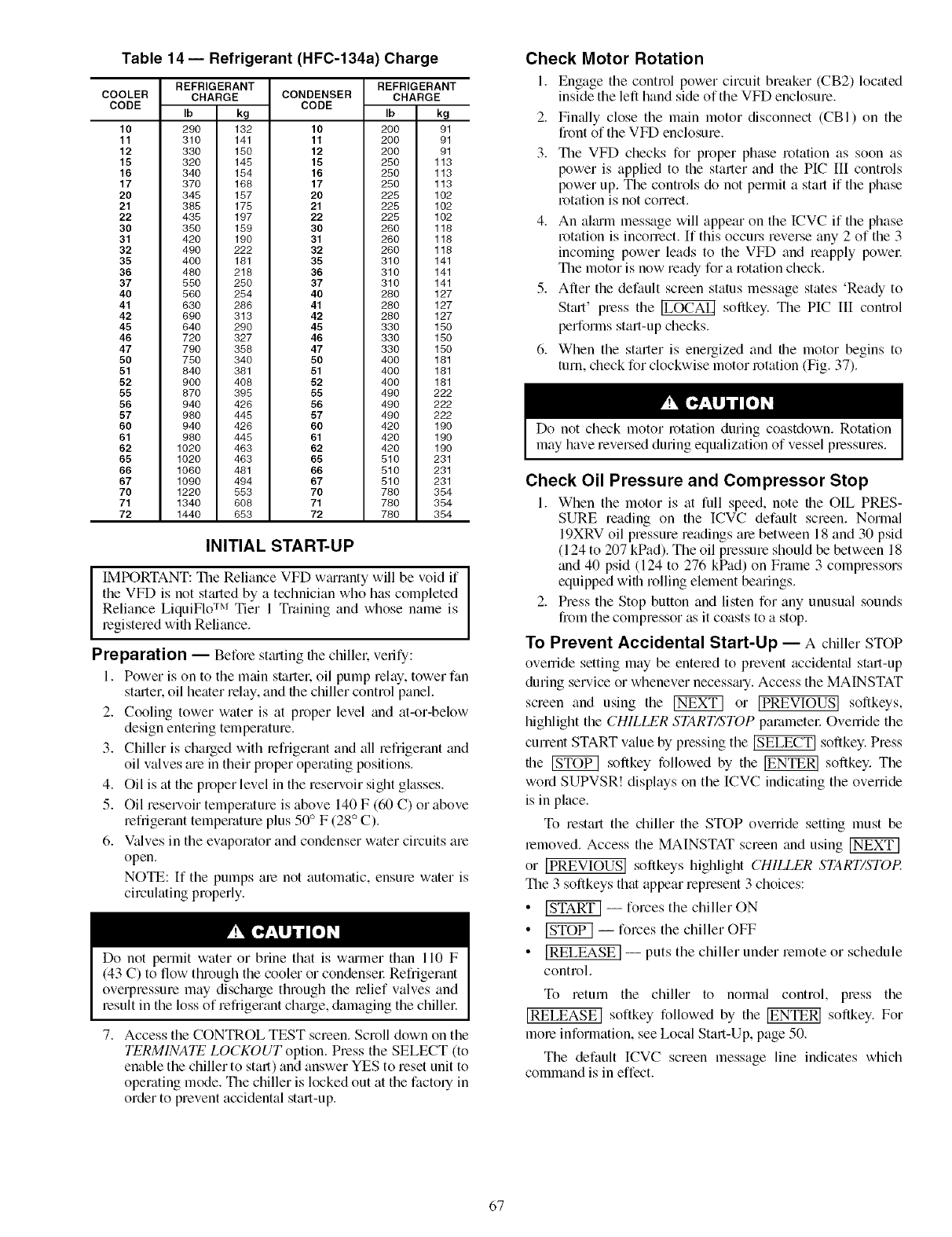
Table 14- Refrigerant (HFC-134a) Charge
COOLER
CODE
10
11
12
15
16
17
20
21
22
30
31
32
35
36
37
40
41
42
45
46
47
50
51
52
55
56
57
6O
61
62
65
66
67
7O
71
72
REFRIGERANT
CHARGE
Ib kg
290 132
310 141
330 150
320 145
340 154
370 168
345 157
385 175
435 197
350 159
420 190
490 222
400 161
480 218
550 250
560 254
630 266
690 313
640 290
720 327
790 358
750 340
840 361
900 408
870 395
940 426
980 445
940 426
980 445
1020 463
1020 463
1060 461
1090 494
1220 553
1340 608
1440 653
REFRIGERANT
CONDENSER CHARGE
CODE Ib kg
10 200 91
11 200 91
12 200 91
15 250 113
16 250 113
17 250 113
20 225 102
21 225 102
22 225 102
30 260 118
31 260 118
32 260 118
35 310 141
36 310 141
37 310 141
40 260 127
41 280 127
42 280 127
45 330 150
46 330 150
47 330 150
50 400 161
51 400 161
52 400 181
55 490 222
56 490 222
57 490 222
60 420 190
61 420 190
62 420 190
65 510 231
66 510 231
67 510 231
70 780 354
71 780 354
72 780 354
INITIAL START-UP
IMPORTANT: The Reliance VFD wmTanty will be void if
the VFD is not stmted by a technician who has completed
Reliance LiquiFlo TM Tier 1 Training and whose name is
legi stered with Reliance.
Preparation -- Before stmting file chillel; verify:
I. Power is on to the main startel: oil pump relay, tower fan
stmter, oil heater relay, and file chiller control panel.
2. Cooling tower water is at proper level and at-or-below
design entering temperature.
3. Chiller is charged with refrigerant and all refi'igerant and
oil valves are in their proper operating positions.
4. Oil is at the proper level in the reservoir sight glasses.
5. Oil reservoir temperature is above 140 F (60 C) or above
refrigerant temperature plus 50 ° F (28 ° C).
6. Vtdves in the evaporator and condenser water circuits are
open.
NOTE: If the pumps are not automatic, ensure water is
circulating properly.
Do not permit water or brine that is wmmer than 110 F
(43 C) to flow through the cooler or condensel: Refrigerant
overpressure may discharge through the relief valves and
result in the loss of refrigerant charge, damaging the chillel:
7. Access the CONTROL TEST screen. Scroll down on the
TERMINATE LOCKOUT option. Press the SELECT (to
enable the chiller to start) and answer YES to reset unit to
operating mode. The chiller is locked out at the factory in
order to prevent accidental start-up.
Check Motor Rotation
1. Engage tile control power circuit breaker (CB2) located
inside the left hand side of the VFD enclosure.
2.
3.
Finally close the main motor disconnect (CBl) on the
front of the VFD enclosure.
The VFD checks for proper phase rotation as soon as
power is applied to the starter and the PIC III controls
power up. The controls do not permit a start if the phase
rotation is not correct.
4. An ahum message will appear on the ICVC if the phase
rotation is incorrect. If this occurs reverse any 2 of the 3
incoming power leads to the VFD and reapply powel:
The motor is now ready for a rotation check.
5. After the default screen status message states 'Ready to
Stmt' press the _ softkey. The PIC III control
performs start-up checks.
6. When the starter is energized and the motor begins to
turn, check for clockwise motor rotation (Fig. 37).
Do not check motor rotation during coastdown. Rotation
may have reversed during equalization of vessel pressures.
Check Oil Pressure and Compressor Stop
I. When the motor is at full speed, note the OIL PRES-
SURE reading on the ICVC default screen. Normal
19XRV oil pressure readings are between 18 and 30 psid
(124 to 207 kPad). The oil pressure should be between 18
and 40 psid (124 to 276 kPad) on Frame 3 compressors
equipped with rolling element bearings.
2. Press the Stop button and listen for any unusual sounds
from the compressor as it coasts to a stop.
To Prevent Accidental Start-Up -- A chiller STOP
ovenide setting may be entered to prevent accident_d start-up
during service or whenever necessmy. Access the MAINSTAT
screen and using the _ or [PREVIOUS] softkeys,
highlight the CHILLER START/STOP pammetel: Override the
current START value by pressing the _ softkey. Press
file _ softkey followed by the _ softkey. The
word SUPVSR! displays on the [CVC indicating the override
is in place.
To restml the chiller the STOP override setting must be
removed. Access the MAINSTAT screen and using
or ]PREVIOUS] softkeys highlight CHILLER START/STOP.
The 3 softkeys that appear represent 3 choices:
•_ -- forces tile chiller ON
• _ -- forces tile chiller OFF
• ]RELEASE ] -- puts the chiller under remote or schedule
control.
To return the chiller to normal control, press the
]RELEASE] softkey followed by the _ softkey. For
mole information, see Local Start-Up, page 50.
The default [CVC screen message line indicates which
command is in effect.
67
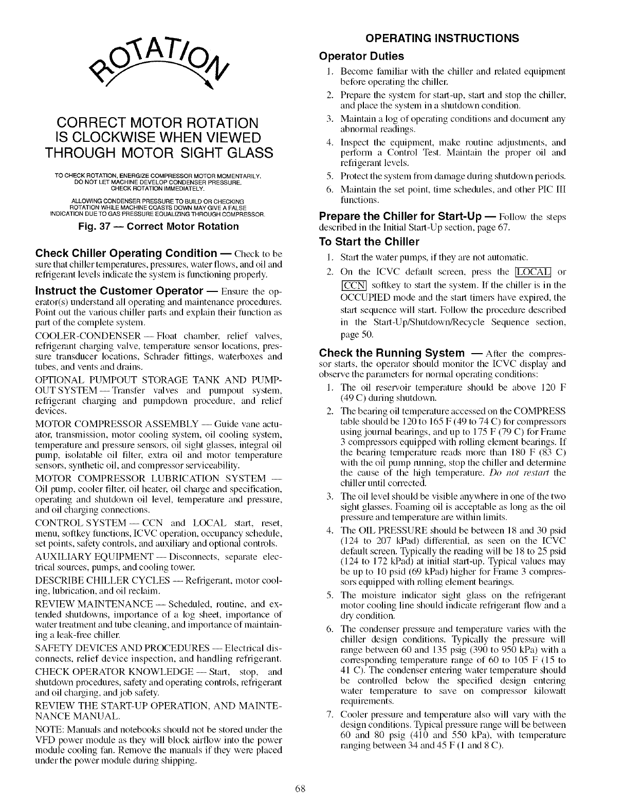
CORRECT MOTOR ROTATION
IS CLOCKWISE WHEN VIEWED
THROUGH MOTOR SIGHT GLASS
TO CHECK ROTATION, ENERGIZE COMPRESSOR MOTOR MOMENTARILY.
DO NOT LET MACHINE DEVELOP CONDENSER PRESSURE.
CHECK ROTATION IMMEDIATELY.
ALLOWING CONDENSER PRESSURE TO BUILD OR CHECKING
ROTATION WHILE MACHINE COASTS DOWN MAY GIVE A FALSE
INDICATION DUE TO GAS PRESSURE EQUALIZING THROUGH COMPRESSOR.
Fig. 37 -- Correct Motor Rotation
Check Chiller Operating Condition -- Clleck to be
sure that chiller temperatures, pressures, water flows, find oil find
lefiigemnt levels indicate the system is functioning properly.
Instruct the Customer Operator -- Ensure the op-
erator(s) understand all operating and maintenance procedures.
Point out the various chiller parts and explain their function as
pa-t of file complete system.
COOLER-CONDENSER--Float chamber, relief valves,
refrigerant charging valve, temperatme sensor locations, pres-
sure transducer locations, Schmder fittings, waterboxes and
tubes, and vents find drains.
OPTIONAL PUMPOUT STORAGE TANK AND PUMP-
OUT SYSTEM -- Transfer vfdves find pumpout system,
refrigerant charging and pumpdown procedme, find relief
devices.
MOTOR COMPRESSOR ASSEMBLY -- Guide vane actu-
ator: transmission, motor cooling system, oil cooling system,
temperature and pressure sensors, oil sight glasses, integral oil
pump, isolatable oil Iiltel; extra oil and motor temperature
sensol_, synthetic oil, find compressor serviceability.
MOTOR COMPRESSOR LUBRICATION SYSTEM --
Oil pump, cooler filter, oil heatel: oil charge and specification,
operating and shutdown oil level, temperature and pressure,
and oil charging connections.
CONTROL SYSTEM--CCN and LOCAL start, reset,
menu, softkey functions, ICVC operation, occupancy schedule,
set points, safety controls, find auxiliay and optiomd controls.
AUXILIARY EQUIPMENT-- Disconnects, sepmate elec-
trical sources, pumps, and cooling towel:
DESCRIBE CHILLER CYCLES -- Refi'igerant, motor cool-
ing, lubrication, and oil reclaim.
REVIEW MAINTENANCE- Scheduled, routine, and ex-
tended shutdowns, importance of a log sheet, importance of
water treatment and tube cleaning, and importance of maintain-
ing a leak-free chiller
SAFETY DEVICES AND PROCEDURES -- Electrical dis-
connects, relief device inspection, and handling refrigerant.
CHECK OPERATOR KNOWLEDGE-- Stm-t, stop, and
shutdown procedures, safety and operating controls, refrigerant
and oil charging, and job safety.
REVIEW THE START-UP OPERATION, AND MAINTE-
NANCE MANUAL.
NOTE: Manufds find notebooks should not be stored under the
VFD power module as they will block airflow into the power
module cooling fan. Remove the manuals if they were placed
under the power module during shipping.
OPERATING INSTRUCTIONS
Operator Duties
I. Becolne falniliar with the chiller and related equiplnent
before operating the cNllel:
2. Prepare the system for start-up, start and stop the chiller.
and place the system in a shutdown condition.
3. Maintain a log of operating conditions and document any
abnormal readings.
4. Inspect the equipment, make routine adjustments, fred
perform a Control Test. Maintain the proper oil and
refrigerant levels.
5. Protect the system from &image during shutdown periods.
6. Maintain the set point, time schedules, and other PIC HI
functions.
Prepare the Chiller for Start-Up -- Follow the steps
described in the Initial Start-Up section, page 67.
To Start the Chiller
I. Start the water pumps, if they are not automatic.
2. On the ICVC default screen, press the _ or
[_ soflkey to start the system. If the chiller is in the
OCCUPIED mode find the start timel_ have expired, the
stfu-t sequence will start. Follow the procedure described
in the Start-Up/Shutdown/Recycle Sequence section,
page 50.
Check the Running System -- After the compres-
sor starts, the operator should monitor the ICVC display find
observe the parameters for normal operating conditions:
1. The oil reselaToir temperature should be above 120 F
(49 C) during shutdown.
2. The bearing oil temperature accessed on the COMPRESS
table should be 120 to 165 F (49 to 74 C) for compressors
using journal bemings, and up to 175 F (79 C) for Frame
3 compressors equipped with rolling element bemings. If
the bearing temperatme reads more than 180 F (83 C)
wifll the oil pump running, stop the chiller and determine
the cause of the high temperature. Do not restart the
chiller until corrected.
3. The oil level should be visible anywhere in one of the two
sight glasses. Foaming oil is acceptable as long as the oil
pressure and temperature are within limits.
4. The OIL PRESSURE should be between 18 and 30 psid
(124 to 207 kPad) differential, as seen on the ICVC
default screen. Typically the reading will be 18 to 25 psid
(124 to 172 kPad) at initial start-up. Typical values may
be up to 10 psid (69 kPad) higher for Frame 3 compres-
sors equipped with rolling element bearings.
5. The moisture indicator sign glass on the refrigerant
motor cooling line should indicate refrigerant flow and a
dry condition.
6. The condenser pressure and temperature varies with the
chiller design conditions. Typically the pressure will
range between 60 and 135 psig (390 to 950 kPa) with a
corresponding temperature range of 60 to 105 F (15 to
41 C). The condenser entering water temperature should
be controlled below the specified design entering
water temperature to save on compressor kilowatt
requirements.
7. Cooler pressure and temperature also will vary with the
design conditions. Typical pressure range will be between
60 and 80 psig (410 and 550 kPa), with temperature
ranging between 34 find 45 F (1 and 8 C).
68
8. Thecompressormayoperateatfullcapacityforashort
timeafterthepulldownrampinghasended,eventhough
thebuildingloadissm_dl.Theactiveelectric_ddemand
settingcanbeoveMddentolimitthecompressor[kW.or
thepulldownrotecanbedecreasedto avoida high
demandchaisefor theshortperiodof highdemand
operation.Pulldownratecanbebasedonloadrateor
temperaturerateandisaccessedontheEQUIPMENT
SERVICEscreen,RAMPDEM table (N_ble4,
Example21).
To Stop the Chiller
I. The occupancy schedule starts and stops the chiller
automatically once the time schedule is configured.
2. By pressing the STOP button for one second, the alarm
light blinks once to confirm the button has been pressed.
The compressor will then follow the normal shutdown
sequence as described in the Shutdown Sequence,
Start-Up/Shutdown/Recycle Sequence section, page 50.
The chiller will not restmt until the _ or
softkey is pressed. The chiller is now in the OFF control
mode.
lIMPORTANT: Do not attempt to stop the chiller by openingan isolating knife switch. High intensity arcing may occm:
Do not restart the chiller until the problem is diagnosed
and corrected.
After Limited Shutdown-- No speci_d preparations
should be necessary. Follow the regular preliminary checks and
starting procedures.
Preparation for Extended Shutdown -- The refrig-
erant should be transferred into the pumpout storage tank (if
supplied; see Pumpout and Refiigermlt Transfer Procedures) to
reduce chiller pressure and the possibility of leaks. Maintain a
holding ch;uge of 5 to 10 lb (2.27 to 4.5 kg) of refrigerant or
nitrogen to prevent air from leaking into the chillel:
If freezing temperatures ;u'e likely to occur in the chiller
area, drain the chilled watel: condenser watel; and the pumpout
condenser water circuits to avoid freeze-up. Keep the waterbox
drains open.
Leave the oil ch;uge in the chiller with the oil heater and
controls energized to maintain the minimum oil reservoir
temperature.
After Extended Shutdown -- Ensure the water sys-
tem drains ;u'e closed. It may be advisable to flush the water
circuits to remove any soft rust which may have formed. This
is a good time to brash the tubes and inspect the Schrader
fittings on the waterside flow devices for fouling, if necessary.
Check the cooler pressure on the ICVC default screen and
compare it to the original holding charge that was left in the
chillel: [f (after adjusting for ambient temperature changes) any
loss in pressure is indicated, check for refrigerant leaks. See
Check Chiller Tightness section, page 53.
Recharge the chiller by transferring refrigerant from the
pumpout storage tank (if supplied). Follow the Pumpout and
Refrigerant Transfer Procedures section, page 71. Observe
freeze-up precautions.
C;uefully make all legular preliminary and running system
checks. Perform a Control Test before start-up. If the compres-
sor oil level appears abnormally high, the oil may have
absorbed refrigerant. Ensme that the oil temperatme is above
140 F (60 C) or above the cooler refrigerant temperature plus
50 ° F(27 ° C).
Cold Weather Operation- When the entering con-
denser water temperature drops very low. the operator should
automatically cycle the cooling tower fans off to keep the
temperature up. Piping may ;dso be arranged to bypass the
cooling towel: The PIC llI controls have a low limit tower fan
output that can be used to assist in this control (terminals 5 and
6 on the TB2 haz;udous voltage field wiring terminal strip).
Manual Guide Vane Operation -- It is possible to
manually operate the guide vanes in order to check control
operation or to control the guide vanes in an emergency. Manu-
;d operation is possible by overriding the tinget guide vane
position. Access the COMPRESS screen on the ICVC and
scroll down to highlight TARGET GUIDE VANE POS. To
control the position, use the [INCREASE] or [DECREASE]
softkey to adjust to the percentage of guide vane opening that is
desired. Zero percent is fully closed; 100% is fully open. To
release the guide vanes to automatic control, press the
[RELEASEJ softkey.
Similarly. the TARGET VFD SPEED can be manu;dly set
in the COMPRESS screen. The target value is still limited to be
between configured VFD MINIMUM SPEED and VFD
MAXIMUM SPEED. Once speed is manually set in this man-
nel, capacity control changes are directed to modulate the
guide vanes.
NOTE: Manual control mode overrides the configured pull-
down ramp rate during st;ut-up and permits the guide vanes to
open at a faster rate. The PIC lII controls will close the guide
vanes if the motor current exceeds the ACTIVE DEMAND
LIMIT or capacity override limits. The guide vanes will
_flso close if the chilled water temperature falls below the
CONTROL POINT. For descriptions of capacity overrides and
set points, see the Controls section.
Refrigeration Log- A refrigeration log (as shown in
Fig. 38), is a convenient checklist for routine inspection and
maintenance and provides a continuous record of chiller
performance. It is also an aid when scheduling routine mainte-
nance and diagnosing chiller problems.
Keep a record of the chiller pressmes, temperatures, and liq-
uid levels on a sheet similar to the one in Fig. 38. Automatic
recording of PIC [II data is possible by using CCN devices
such as the Data Collection module and a Building Supervisol:
Contact a C_urier representative for more information.
69
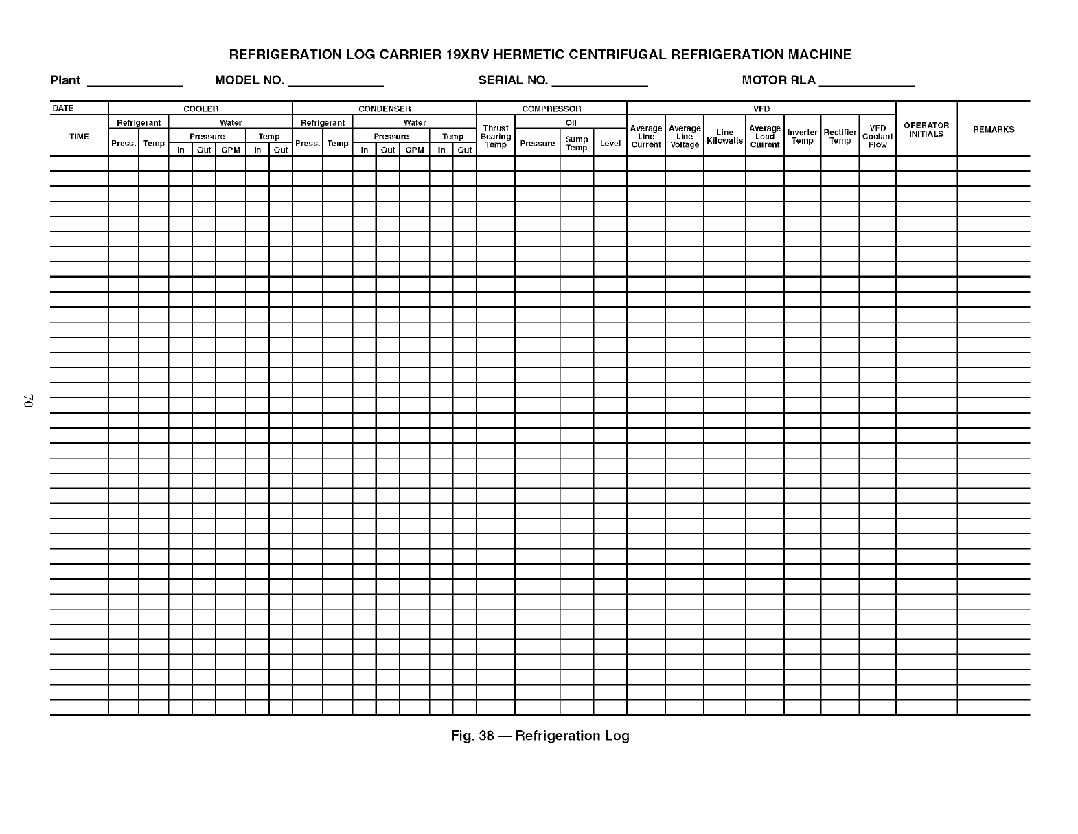
_j
Plant
DATE
TIME
Refrigerant
Press. Temp
REFRIGERATION LOG CARRIER 19XRV HERMETIC CENTRIFUGAL REFRIGERATION MACHINE
MODEL NO. SERIAL NO. MOTOR RLA
COOLER
Water
Pressure
In Out GPM
CONDENSER COMPRESSOR VFD
Refrigerant Water Oil
Thrust Average Average Line Average
Line Line Load
InTemPout Press. Temp In PressUreoutGPM InTemPout BearingTempPressure SumPTempLevel Current Voltage Kilowatts Current
Inverter Rectifier
Temp Temp
VFD
Coolant
Flow
OPERATOR REMARKS
INITIALS
Fig. 38 -- Refrigeration Log
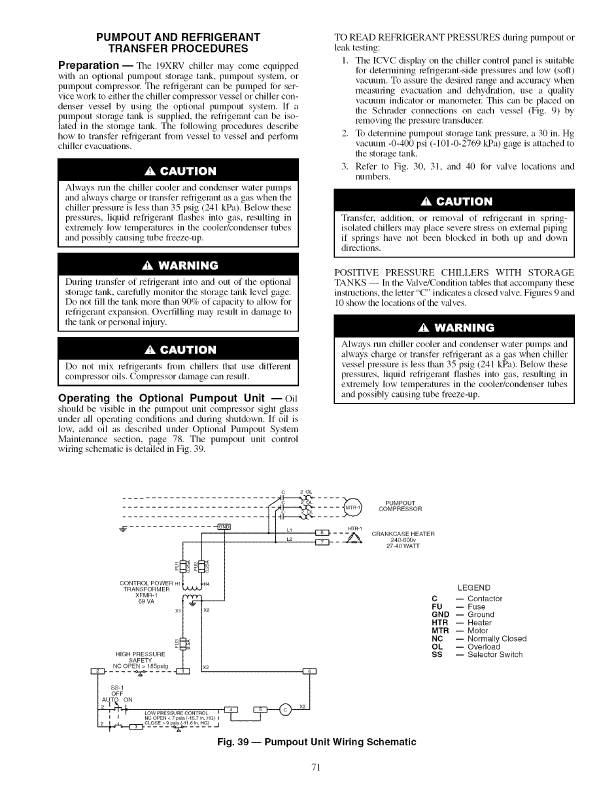
PUMPOUT AND REFRIGERANT
TRANSFER PROCEDURES
Preparation -- The 19XRV chiller equippedlllay COllie
wifll an optional pumpout storage tank, pumpout system, or
pumpout compressol: The refrigerant can be pumped for ser-
vice work to either the chiller compressor vessel or chiller con-
denser vessel by using the optional pumpout system. If a
pumpout storage tank is supplied, the refrigerant can be iso-
laed in the storage tank. The following procedures describe
how to transfer refrigerant from vessel to vessel and perfonn
chiller evacuaions.
Always run the chiller cooler and condenser water pumps
and always charge or transfer refrigerant as a gas when the
chiller pressure is less than 35 psig (241 kPa). Below these
pressures, liquid refrigerant flashes into gas, resulting in
extremely low temperatures in the cooler/condenser tubes
and possibly causing tube freeze-up.
TO READ REFRIGERANT PRESSURES during pumpout or
leak testing:
1. The ICVC dispkly on file chiller control panel is suitable
for determining refrigerant-side pressures and low (soft)
vacuum. To assure the desired range and accuracy when
measuring evacuation and dehydration, use a quality
vacuum indicator or manometel: This can be placed on
file Schrader connections on each vessel (Fig. 9) by
removing the pressure transducel:
2. To determine pumpout storage tank pressure, a 30 in. Hg
vacuum -0-400 psi (-101-0-2769 kPa) gage is attached to
file storage tank.
3. Refer to Fig. 30, 31, and 40 for valve locations and
numbers.
Transfer. addition, or removal of refrigerant in spring-
isolated chillers may place severe stress on external piping
if springs have not been blocked in both up and down
directions.
During transfer of refrigerant into and out of the optional
storage tank, carefully monitor the storage tank level gage.
Do not fill the tank more than 90% of capacity to _fllow for
refrigerant expansion. Overfilling may result in dmnage to
the tank or personal injury.
Do not mix lefrigerants from chillers that use different
compressor oils. Compressor &image can result.
Operating the Optional Pumpout Unit --Oil
should be visible in the pumpout unit compressor sight glass
under all operating conditions and during shutdown. If oil is
low. add oil as described under Optional Pumpout System
Maintenance section, page 78. The pumpout unit control
wiring schematic is detailed in Fig. 39.
POSITIVE PRESSURE CHILLERS WITH STORAGE
TANKS -- In the Valve/Condition tables ilia accompany these
instructions, file letter "C" indicates a closed v_dve. Figures 9 and
10 show the locations of the valves.
Always run chiller cooler and condenser waer pumps and
always charge or transfer refrigerant as a gas when chiller
vessel pressure is less than 35 prig (241 kPa). Below these
pressures, liquid refrigerant flashes into gas, resulting in
extremely low temperatures in the cooler/condenser tubes
and possibly causing tube freeze-up.
D D
CONTROL POWER H1 H4
TRANSFORMER
XFMR-1 _ x2
6oVA
HIGH PRESSURE
SAFETY
-- AUTO-N-C-OP _'_185-P _9"-SS-1OFF ON )<2
2_ "_m _ LOW PRESSURE CONTROL I
L_J'-I_| E_ NC_O-_SE-.> 2OPEN < _7 psia E15.7"6i_L H.?Lin"HG}jI
Fig. 39 -- Pumpout Unit Wiring Schematic
C 20L
C_-----_-_-2 L .... _ PUMPOUT
_-::-_ COMPRESSOR
L1 _ -- -- --HZ_'I CRANKCASE HEATER
L2 ___ 240-600v
27-40 WATT
LEGEND
C -- Contactor
FU -- Fuse
GND -- Ground
HTR -- Heater
MTR -- Motor
NC -- Normally Closed
OL -- Overload
SS -- Selector Switch
71
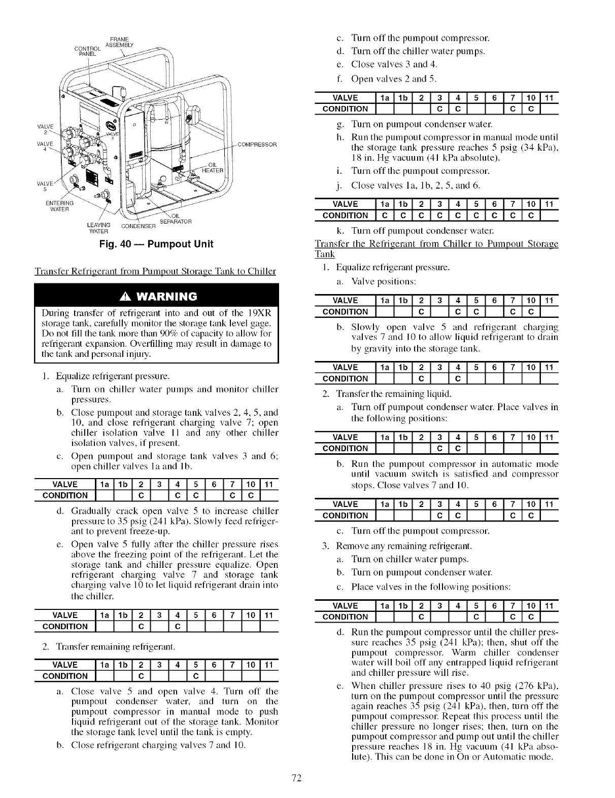
FRAME
ASSEMBLY
CONTROL
PANEL
VALVE
2_
VALVE
4_
VALVE /
5
ENTERING
WATER
_COMPRESSOR
/OIL
SEPARATOR
LEAVING CONDENSER
WATER
Fig. 40 -- Pumpout Unit
Transfer Refrigerant fiOl]l Pumpout Storage Tank to Chiller
c. Turn off tile pumpout compressor.
d. Turn off the chiller water pumps.
e. Close valves 3 and 4.
f. Open valves 2 and 5.
VALVE la lb 2 34 5 6 7 10 11
CONDITION C C C C
g. Turn on pumpout condenser watec
h. Run the pumpout compressor in manual mode until
the storage tank pressure reaches 5 psig (34 kPa),
18 in. Hg vacuum (41 kPa absolute).
i. Turn off the pumpout compressor.
j. Close valves I a, I b, 2, 5, and 6.
VALVE la lb 2 34 5 6 7 10 11
CONDITION C C C C C C C C C
k. Turn off pumpout condenser watel:
Transfer the Refrigerant from Chiller to Pumpout Storage
Tank
1. Equalize refrigerant pressure.
a. Valve positions:
During transfer of refrigerant into and out of the 19XR
storage tank, carelhlly monitor the storage tank level gage.
Do not fill the tank more than 90% of capacity to allow for
refrigerant expansion. Overfilling may result in &image to
the tank and personal injury.
Equ_dize refligerant pressure.
a. Turn on chiller water pumps and monitor chiller
pressures.
b. Close pumpout and storage tank valves 2, 4, 5, and
10, and close refrigerant charging valve 7; open
chiller isolation valve 11 and any other chiller
isolation valves, if present.
c. Open pumpout and storage tank valves 3 and 6;
open chiller valves la and lb.
VALVE la lb 2 34 5 6 7 10 11
CONDITION C C C C C
d. Gradually crack open valve 5 to increase chiller
pressure to 35 psig (241 kPa). Slowly feed refriger-
ant to prevent freeze-up.
e. Open valve 5 fully after the chiller pressure rises
above the freezing point of the refrigerant. Let the
storage tank and chiller pressure equalize. Open
refrigerant charging valve 7 and storage tank
charging valve 10 to let liquid refrigerant drain into
the chiller.
VALVE ]la lb 2 3 4 5 6 7 10 11
CONDITION
2. Transfer remaining refrigerant.
VALVE 11
CONDITION
a. Close valve 5 and open valve 4. Turn off the
pumpout condenser water, and turn on the
pumpout compressor in manual mode to push
liquid refrigerant out of the storage tank. Monitor
the storage tank level until the tank is empty.
b. Close refrigerant charging valves 7 and 10.
VALVE la lb 2 3 4 5 6 7 10 11
CONDITION C C C C C
b. Slowly open wflve 5 and refrigerant charging
valves 7 and 10 to allow liquid refrigerant to drain
by gravity into the storage tank.
VALVE 11
CONDITION
2. Transfer the remaining liquid.
a. Turn off pumpout condenser water. Place valves in
the following positions:
VALVE 11
CONDITION
b. Run the pumpout compressor in automatic mode
until vacuum switch is satisfied and compressor
stops. Close valves 7 and 10.
VALVE la lb 2 3 4 5 6 7 10 11
CONDITION C C C C
c. Turn off the pumpout compressor.
3. Remove any remaining refrigerant.
a. Turn on chiller water pumps.
b. Turn on pumpout condenser watec
c. Place valves in the following positions:
Run the pumpout compressor until the chiller pres-
sure reaches 35 psig (241 kPa); then, shut off the
pumpout compressor. Warm chiller condenser
water will boil off any entrapped liquid refrigerant
and chiller pressure will rise.
When chiller pressure rises to 40 psig (276 kPa),
turn on the pumpout compressor until the pressure
again reaches 35 psig (241 kPa), then, turn off the
pumpout compressor. Repeat this process until the
chiller pressure no longer rises; then, turn on the
pumpout compressor and pump out until the chiller
pressure reaches 18 in. Hg vacuum (41 kPa abso-
lute). This can be done in On or Automatic mode.
72
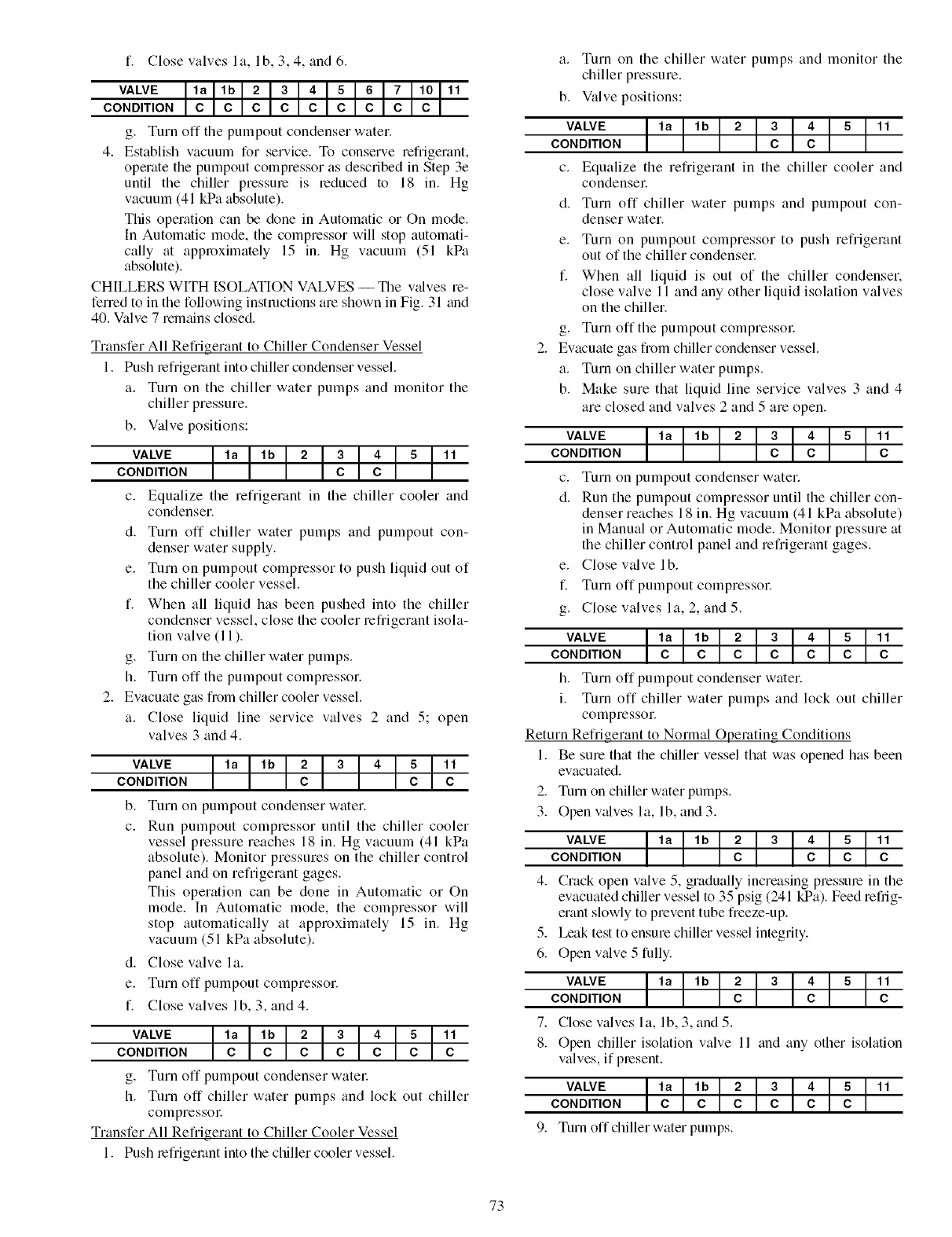
f. Close valves I a, I b, 3, 4, and 6.
VALVE la lb 2 3 4 5 6 7 10 11
CONDITION C C C C C C C C C
g. Turn off the pumpout condenser water.
4. Establish vacuum for service. To conserve refrigerant,
operate the pumpout compressor as described in Step 3e
until the chiller pressure is reduced to 18 in. Hg
vacuum (41 kPa absolute).
This operation can be done in Automatic or On mode.
In Automatic mode, the compressor will stop automati-
cally at approximately 15 in. Hg vacuum (51 kPa
absolute).
CH[LLERS WITH ISOLATION VALVES -- Tile valves re-
ferred to in the following instructions are shown in Fig. 31 and
40. Valve 7 remains closed.
Transfer All Refrigerant to Chiller Condenser Vessel
1. Push lefrigemnt into chiller condenser vessel.
a. Turn on the chiller water pumps and monitor the
chiller pressure.
b. Valve positions:
VALVE _ 11CONDITION
c. Equalize the refrigerant in the chiller cooler and
condenseE
d. Turn off chiller water pumps and pumpout con-
denser water supply.
e. Turn on pumpout compressor to push liquid out of
the chiller cooler vessel.
f. When all liquid has been pushed into the chiller
condenser vessel, close the cooler refrigerant isola-
tion valve (11 ).
g. Turn on the chiller water pumps.
h. Turn off the pumpout compressor.
2. Evacuate gas from chiller cooler vessel.
a. Close liquid line service valves 2 and 5; open
valves 3 and 4.
VALVE
CONDITION
b.
c.
11c
Turn on pumpout condenser water.
Run pumpout compressor until the chiller cooler
vessel pressure reaches 18 in. Hg vacuum (41 kPa
absolute). Monitor pressures on the chiller control
panel and on refrigerant gages.
This operation can be done in Automatic or On
mode. In Automatic mode, the compressor will
stop automatically at approximately 15 in. Hg
vacuum (51 kPa absolute).
d. Close valve la.
e. Turn off pumpout compressor.
f. Close valves lb, 3, and 4.
VALVE _ 11
CONDITION C
g. Turn off pumpout condenser watel:
h. Turn off chiller water pumps and lock out chiller
compressoc
Transfer All Refrigerant to Chiller Cooler Vessel
1. Push lefiigemnt into the chiller cooler vessel.
a. Turn on the chiller water pumps and monitor the
chiller pressure.
b. Valve positions:
VALVE _ 11
CONDITION
c. Equalize the refrigerant in the chiller cooler and
condensel:
d. Turn off chiller water pumps and pumpout con-
denser water.
e. Turn on pumpout compressor to push refrigerant
out of the chiller condenser.
f. When all liquid is out of the chiller condenser.
close valve 11 and any other liquid isolation valves
on the chiller.
g. Turn off the pumpout compressol:
Evacuate gas from chiller condenser vessel.
a. Turn on chiller water pumps.
b. Make sure that liquid line service valves 3 and 4
are closed and valves 2 and 5 are open.
VALVE _ 11CONDITION C
c. Tnrn on pumpout condenser water.
d. Run the pumpout compressor until the chiller con-
denser reaches 18 in. Hg vacuum (41 kPa absolute)
in Manual or Automatic mode. Monitor pressure at
the chiller control panel and refrigerant gages.
e. Close valve lb.
f. Turn off pumpout compressor.
g. Close valves la, 2, and 5.
VALVE _ 11CONDITION C
h. Turn off pumpout condenser water.
i. Turn off chiller water pumps and lock out chiller
compressoE
Return Refrigerant to Normal Operating Conditions
1. Be sure that the chiller vessel that was opened has been
evacuated.
2. Turn on chiller water pumps.
3. Open valves la, lb, and 3.
VALVE _ 11CONDITION C
4. Crack open valve 5, gradually increasing pressure in the
evacuated chiller vessel to 35 psig (241 kPa). Feed refiig-
erant slowly to prevent tube freeze-up.
5. Leak test to ensure chiller vessel integrity.
6. Open v_dve 5 fully.
7.
8.
VALVE _ 11CONDITION C
Close valves la, lb, 3, and 5.
Open chiller isolation valve 11 and any other isolation
valves, if present.
VALVE _ 11CONDITION
Turn off chiller water pumps.
73
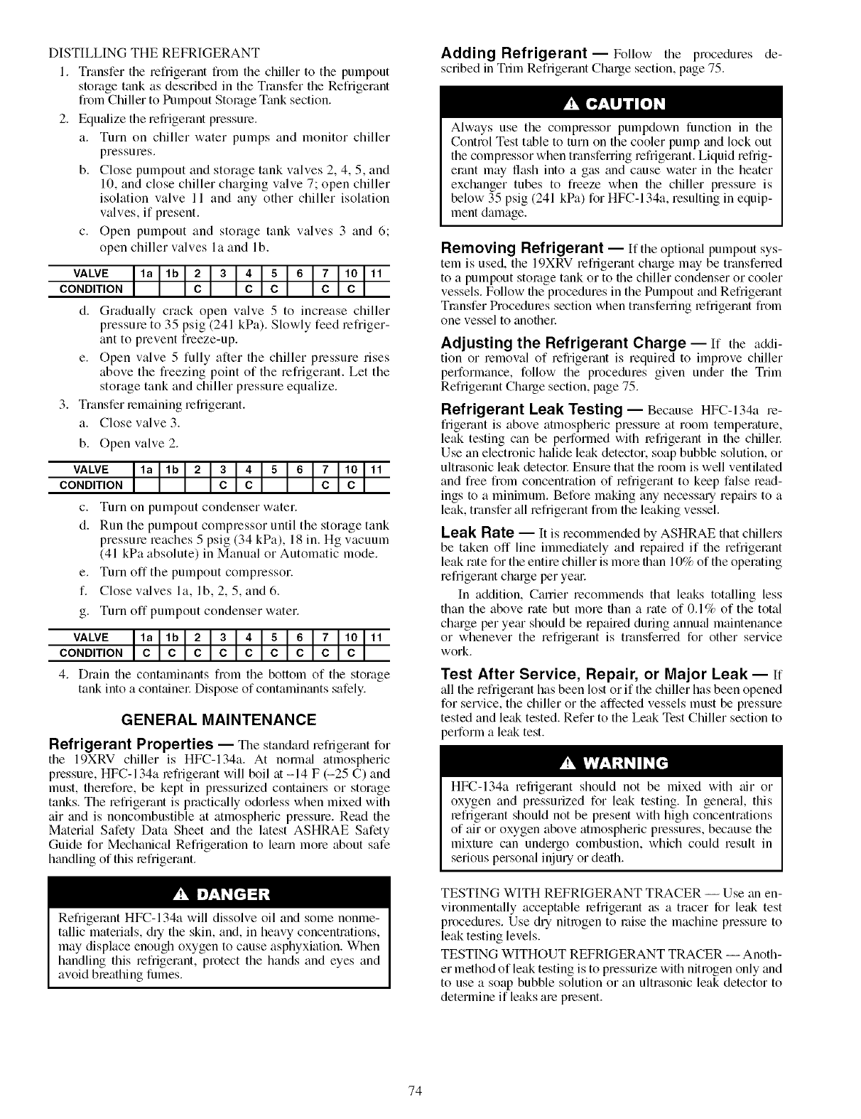
DISTILLING THE REFRIGERANT
1. Transfer the refligerant flom the chiller to the pumpout
storage tank as described in the Transfer the Refligerant
from Chiller to Pumpout Storage Tank section.
2. Equalize the refl'igerant pressure.
a. Turn on chiller water pumps and monitor chiller
pressures.
b. Close pumpout and storage tank valves 2, 4, 5, and
10, and close chiller charging valve 7; open chiller
isolation valve 11 and any other chiller isolation
valves, if present.
c. Open pumpout and storage tank valves 3 and 6;
open chiller valves la and lb.
VALVE la lb 234 5 6 7 10 11
CONDITION C C C C C
d. Gradually crack open valve 5 to increase chiller
pressure to 35 psig (241 kPa). Slowly feed refriger-
ant to prevent freeze-up.
e. Open valve 5 fully after the chiller pressure rises
above the freezing point of the refrigerant. Let the
storage tank and chiller pressure equalize.
3. Transfer remaining refrigerant.
a. Close valve 3.
b. Open valve 2.
c. Turn on pumpout condenser water.
d. Run the pumpout compressor until the storage tank
pressure reaches 5 psig (34 kPa), 18 in. Hg vacuum
(41 kPa absolute) in Manual or Automatic mode.
e. Turn off the pumpout compressor.
f. Close valves la, lb, 2, 5, and 6.
g. Turn off pumpout condenser water.
VALVE la lb 2 3 4 5 6 7 10 11
CONDITION C C C C C C C C C
4. Drain the contaminants from the bottom of the storage
tank into a containel: Dispose of contaminants safely.
GENERAL MAINTENANCE
Refrigerant Properties -- The standard refrigerant for
the 19XRV chiller is HFC-134a. At normal atmospheric
pressure, HFC-134a refrigerant will boil at -14 F (-25 C) and
must, therefore, be kept in pressurized containel.s or storage
tanks. The refrigerant is practically odorless when mixed with
air and is noncombustible at atmospheric pressure. Read the
Material Safety Data Sheet and the latest ASHRAE Safety
Guide for Mechanical Refrigeration to learn more about safe
handling of this refrigerant.
Refrigerant HFC-134a will dissolve oil and some nonme-
tallic materials, dqthe skin, and, in heavy concentrations,
may displace enough oxygen to cause asphyxiation. When
handling this refrigerant, protect the hands and eyes and
avoid breathing fumes.
Adding Refrigerant--Follow the procedures de-
scribed in Trim Refrigerant Charge section, page 75.
Always use the compressor pumpdown function in the
Control Test table to turn on the cooler pump and lock out
the compressor when transfen'ing refrigerant. Liquid reflig-
emnt may flash into a gas and cause water in the heater
exchanger tubes to freeze when the chiller pressure is
below 35 psig (241 kPa) for HFC-134a, resulting in equip-
ment damage.
Removing Refrigerant -- If the optional pumpout sys-
tem is used, the 19XRV refrigerant charge may be transferred
to a pumpout storage tank or to the chiller condenser or cooler
vessels. Follow the procedures in the Pumpout and Refrigerant
Transfer Procedmes section when transferringrefrigerant from
one vessel to another:
Adjusting the Refrigerant Charge -- If the addi-
tion or removal of refrigerant is required to improve chiller
performance, follow the procedures given under the Trim
Refrigerant Chmge section, page 75.
Refrigerant Leak Testing -- Because HFC-134a re-
frigerantis above atmospheric pressure at room temperature,
leak testing can be performed with refrigerant in the chillel:
Use an electronic halide leak detector, soap bubble solution, or
ultrasonic leak detectol: Ensure that the room is well ventilated
and free from concentration of refrigerant to keep false read-
ings to a minimum. Before making aW necessguy repairs to a
leak, transfer all refrigerant from the leaking vessel.
Leak Rate -- It is recommended by ASHRAE that chillers
be taken off line immediately and repaired if the refrigerant
leak rate for the entire chiller is more than 10% of the operating
refrigerant charge per yegu:
In addition, Carrier recommends that leaks totalling less
than the above rate but more than a rate of 0.1% of the total
chguge per yegu should be lepaired during annu_d maintenance
or whenever the refrigerant is transferred for other service
work.
Test After Service, Repair, or Major Leak- If
all the refrigerant has been lost or if the chiller has been opened
for service, the chiller or the affected vessels must be pressure
tested and leak tested. Refer to the Leak Test Chiller section to
perform a leak test.
HFC-134a refrigerant should not be mixed with air or
oxygen and pressurized for leak testing. In general, this
refrigerant should not be present with high concentrations
of air or oxygen above atmospheric pressures, because the
mixture can undergo combustion, which could result in
serious personal injury or death.
TESTING WITH REFRIGERANT TRACER -- Use an en-
vironmentally acceptable refrigerant as a tracer for leak test
procedures. Use dry nitrogen to raise the machine pressure to
leak testing levels.
TESTING WITHOUT REFRIGERANT TRACER -- Anoth-
er method of leak testing is to pressurize with nitrogen only and
to use a soap bubble solution or an ultrasonic leak detector to
determine if leaks are present.
74
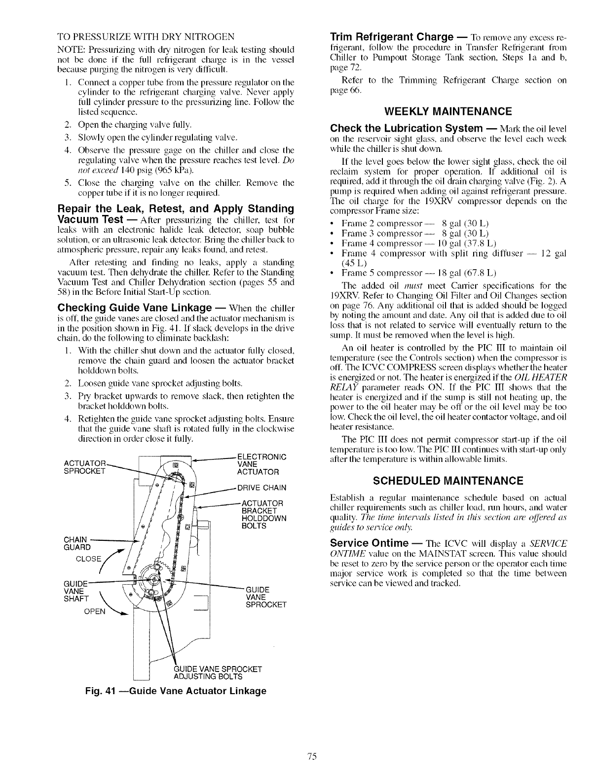
TO PRESSURIZE WITH DRY NITROGEN
NOTE: Pressurizing with dUnitrogen for leak testing should
not be done if the full refiigerant charge is in the vessel
because purging file nitrogen is veUdill]cult.
1. Connect a copper tube fiom the pressure regulator on the
cylinder to the refligemnt charging valve. Never apply
full cylinder pressure to the pressurizing line. Follow the
listed sequence.
2. Open file charging valve fully.
3. Slowly open the cylinder regulating valve.
4. Observe the pressure gage on the chiller and close the
regulating valve when the pressure reaches test level. Do
not (,.w_,ed140 psig (965 kPa).
5. Close the charging valve on the chiller. Remove the
copper tube if it is no longer mquimdi
Repair the Leak, Retest, and Apply Standing
Vacuum Test- After pressurizing tile chiller, test for
leaks with an electronic halide leak detectok soap bubble
solution, or an ultrasonic leak detector. Bring the chiller back to
atmospheric pressure, repair aW leaks found, and retest.
After retesting and finding no leaks, apply a standing
vacuum test. Then dehydrate the chiller. Refer to the Standing
Vacuum Test and Chiller Dehydiation section (pages 55 and
58) in the Before [nitial Start-Up section.
Checking Guide Vane Linkage -- When the chiller
is off. the guide vanes are closed and the actuator mechanism is
in the position shown in Fig. 41. [f slack develops in the diive
chain, do the following to eliminate backlash:
1. With the chiller shut down and the actuator fl.dly closed,
remove the chain guard and loosen the actuator bracket
holddown bolts.
2. Loosen guide vane sprocket adjusting bolts.
3. PU bracket upwards to remove slack, then mtighten the
bracket holddown bolts.
4. Retighten the guide vane sprocket adjusting bolts. Ensure
that the guide vane shaft is rotated fully in the clockwise
direction in order close it fully.
3
ACT VANE
SPROCKET ACTUATOR
CHAIN
GUARD
CLOSE
BRACKET
HOLDDOWN
BOLTS
VANE
SHAFT VANE
SPROCKET
Trim Refrigerant Charge -- To reraove any excess re-
frigerant, follow the procednm in Transfer Refrigerant from
Chiller to Pumpout Storage Tank section, Steps la and b,
page 72.
Refer to the Trimming Refligerant Charge section on
page 66.
WEEKLY MAINTENANCE
Check the Lubrication System -- Mark the oil level
on the reservoir sight glass, and observe the level each week
while the chiller is shut down.
If the level goes below the lower sight glass, check the oil
reclaim system for proper operation. If additional oil is
required, add it through the oil di'ain ch_u'gingwdve (Fig. 2). A
pump is required when adding oil against refrigerant pressure.
The oil charge for the 19XRV compressor depends on the
compressor Frmne size:
• Frame 2 compressor-- 8 gal (30 L)
• Frame 3 compressor-- 8 gal (30 L)
• Frame 4 compressor-- 10 gal (37.8 L)
• Frame 4 compressor with split ring diffuser -- 12 gal
(45 L)
• Frame 5 compressor -- 18 gal (67.8 L)
The added oil must meet Career specifications for the
19XRV. Refer to Changing Oil Filter and Oil Changes section
on page 76. Any additional oil that is added should be logged
by noting the amount and date. Any oil that is added due to oil
loss that is not related to service will eventually return to the
sump. It must be removed when the level is high.
An oil heater is controlled by the PIC III to maintain oil
temperature (see the Controls section) when the compressor is
off. The ICVC COMPRESS screen displays whether the heater
is energized or not. The heater is energized if the OIL HEATER
RELAY p_umneter reads ON. [f the PIC III shows that the
heater is energized and if the sump is still not heating up, the
power to the oil heater may be off or the oil level may be too
low. Check the oil level, the oil heater contactor voltage, and oil
heater resistance.
The PIC 1II does not permit compressor start-up if the oil
temperature is too low. The PIC III continues with start-up only
after the temperature is within allowable limits.
SCHEDULED MAINTENANCE
Establish a regular maintenance schedule based on actual
chiller requirements such as chiller load, run hours, and water
quality. The time inteia'als listed in this section an" o_'red as
guides to sem'i_z" onh"
Service Ontime -- The [CVC will display a SERVICE
ONTIME value on the MAINSTAT screen. This value should
be reset to zero by the service person or the operator each time
major service won is completed so that the time between
service can be viewed and tracked.
GUIDE VANE SPROCKET
ADJUSTING BOLTS
Fig. 41 --Guide Vane Actuator Linkage
75
Inspect the Control Panel -- Maintenance consists of
general cleaning and tightening of connections. Vacuum the
cabinet to eliminate dust build-up. If the chiller control
malfunctions, refer to the Troubleshooting Guide section for
control checks and adjustments.
Ensure power to the control center is off when cleaning and
tightening connections inside the control p_mel. Failure to
disconnect power could result in electrocution.
Check Safety and Operating Controls
Monthly -- Check values of monitored parameters (see
Table 6 for safety control settings). To ensure chiller protec-
tion, the Automated Control Test should be performed at
least once per month (with machine in OFF mode). See
Table 12 for Control Test functions.
Changing Oil Filter--Change the oil filter on a
yearly basis or when the chiller is opened for repairs. The
19XRV chiller has an isolatable oil filter so that the filter
may be changed with the refrigerant remaining in the
chiller. Early 19XRV compressors were designed with the
oil filter housing attached to the oil pump. The following
procedure applies to later 19XRV compressors which have
the oil filter separate flom the oil pump.
1. Ensure the compressor is off and the disconnect for the
compressor is open.
2. Disconnect the power to the oil pump.
3. Close the oil filter isolation valves located behind power
panel on top of oil pump assembly.
4. Close the isolation valves located on both ends of the oil
filtel: Have rags and a catch basin available to collect oil
spillage.
5. Equfdize the filter's higher internal pressure to ambient
by connecting an oil charging hose to the Schmder valve
on the oil filter housing. Collect the oil-refrigerant mix-
ture which is dischm'gedi
6. Remove the oil filter assembly by loosening the hex nuts
on both ends of the filter assembly.
7. Insert the replacement tilter assembly with the rerow on
the housing pointing away from the oil pump.
8. Rotate the assembly so that the schraeder drain vfflve is
oriented fit the bottom, and tighten the connection nut on
each end to a torque of approximately 30 ft-lb (41 N-m)
The oil filter housing is at a high pressure. Relieve this
pressure slowly. Failure to do so could result in serious per-
sonal injury.
9. Evacuate the filter housing by placing a vacuum pump on
the charging valve. Follow the normal evacuation proce-
dures. Shut the charging valve when done and reconnect
the valve so that new oil can be pumped into the filter
housing. Fill with the stone amount that was removed;
then close file charging valve.
10. Remove the hose from the chmging valve, open the isola-
tion valves to the filter housing, and turn on the power to
the pump and the motol:
Oil Specification -- If oil is added, it must meet the fol-
lowing Carrier specifications:
Oil Type for units using R-134a .................. Inhibited
polyolester-based synthetic
compressor oil formatted for
use with HFC, gear-driven,
hermetic compressors.
ISO Viscosity Grade ................................. 68
The polyolester-based oil (P/N: PP23BZI03) may be
ordered from a local Carrier representative.
Oil Changes--Cmrier recommends changing the oil
after the first year of operation and every three to five years
thereafter as a minimum in addition to a yedy oil amdysis.
Howevel: if a continuous oil monitoring system is functioning
and a yearly oil analysis is performed, file time between oil
changes can be extended.
TO CHANGE THE OIL
1. Transfer the refrigerant into the chiller condenser vessel
(for isolatable vessels) or to a pumpout storage tank.
2. Mark the existing oil level.
3. Open file control and oil heater circuit breakel:
4. When the chiller pressure is 5 psig (34 kPa) or less, drain
the oil reservoir by opening the oil charging vfdve
(Fig. 2). Slowly open the valve against refrigerant
pressure.
5. Change the oil filter fit this time. See Changing Oil Filter
section.
6. Change the refrigerant filter fit this time, see the next
section, Refrigerant Filtec
7. Charge the chiller with oil. Chmge until the oil level is
equal to the oil level marked in Step 2. Turn on the power
to the oil heater and let file PIC [II warm it up to fit least
140 F (60 C). Operate the oil pump manually, using the
Control Test function, for 2 minutes. For shutdown condi-
tions, the oil level should be full in the lower sight glass.
If the oil level is above 1/2 full in the upper sight glass,
remove the excess oil. The oil level should now be equal
to the amount shown in Step 2.
Refrigerant Filter -- A refrigerant filter/driel, located on
the refrigerant cooling line to the motol; should be changed
once a ye;u or more often if filter condition indicates a need for
more frequent replacement. Change the filter by closing the
filter isolation valves (Fig. 4) and slowly opening the flare
fittings with a wrench and back-up wrench to relieve the pres-
sure. A moisture indicator sight glass is located beyond this
filter to indicate the volume and moisture in the refrigerant. If
the moisture indicator indicates moisture, locate the source of
water immediately by performing a thorough leak check.
Oil Reclaim Filter--The oil reclaim system has a
strainer on file eductor suction line, a strainer on the discharge
pressure line, and a filter on the cooler scavenging line.
Replace file filter once per year or more often if tilter condition
indicates a need for more frequent replacement. Change the
filter by closing the filter isolation valves and slowly opening
the flare fitting with a wrench and back-up wrench to relieve
the pressure. Change the stminel_ once every 5 yeal_ or when-
ever refrigerant is evacuated from the coolel:
76
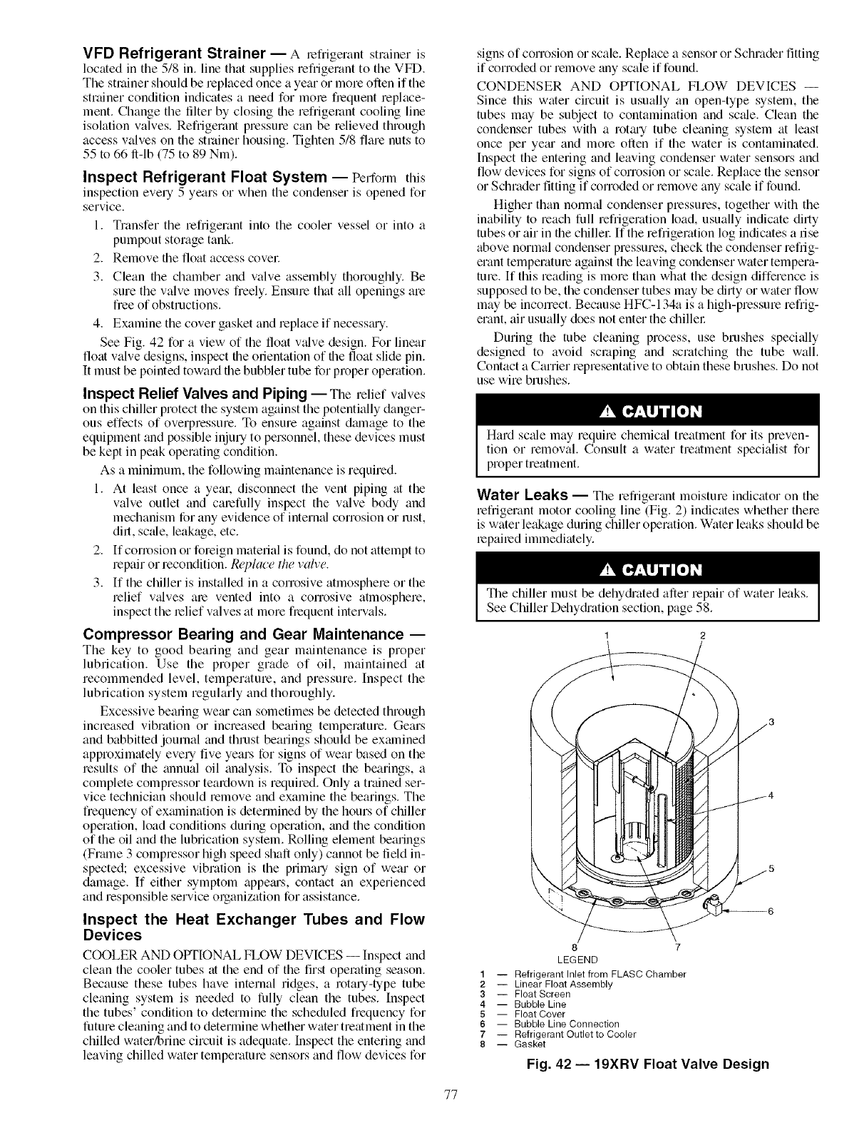
VFD Refrigerant Strainer -- A t_efiigerant strainer is
located in the 5/8 in. line that supplies refiigerant to the VFD.
The strainer should be replaced once a year or more often if the
str;dner condition indicates a need for mote ft_equent replace-
ment. Change the filter by closing the refrigerant cooling line
isolation valves. Refiigerant pressure can be relieved through
access valves on the strainer housing. Tighten 5/8 flare nuts to
55 to 66 ft-lb (75 to 89 Nm).
Inspect Refrigerant Float System -- Perforln this
inspection every 5 years or when the condenser is opened for
service.
1. Transfer the refrigerant into the cooler vessel or into a
pumpout storage tank.
2. Remove the float access covet:
3. Clean the chamber and valve assembly thoroughly. Be
sure the valve moves fieely. Ensure that all openings are
fiee of obstructions.
4. Examine the cover gasket and replace if necessmy.
See Fig. 42 for a view of the float v_dve design. For linear
float valve designs, inspect the orientation of the float slide pin.
It must be pointed toward the bubbler tube for proper operation.
Inspect Relief Valves and Piping -- The relief v_dves
on this chiller protect the system against the potentially danger-
ous effects of overpressure. To ensure against dalnage to the
equipment and possible injury to personnel, these devices must
be kept in peak operating condition.
As a minimum, the following maintenance is required.
1. At least once a yeat: disconnect the vent piping at the
valve outlet and catefttlly inspect the valve body and
mechanism for any evidence of interned corrosion or rest,
dirt, sc_de, leakage, etc.
2. If corrosion or foreign material is found, do not attempt to
repair or recondition. Replace the valve.
3. If the chiller is installed in a corrosive atmosphere or the
relief v_dves ate vented into a corrosive atmosphere,
inspect the relief valves at more fiequent intervals.
Compressor Bearing and Gear Maintenance --
The key to good bearing and gear maintenance is proper
lubrication. Use the proper grade of oil, maintained at
recommended level, temperature, and pressure. Inspect the
lubrication system regularly and thoroughly.
Excessive beating were can sometimes be detected through
increased vibration or increased beating temperature. Gears
and babbitted joumal and thrust bearings should be exalnined
approximately every five years for signs of wear based on the
results of the annual oil analysis. To inspect the bearings, a
complete compressor teatdown is required. Only a trained set-
vice technician should remove and examine the bearings. The
fiequency of exalnination is determined by the hours of chiller
operation, load conditions during opetafion, and the condition
of the oil and the lubrication system. Rolling element bearings
(Frmne 3 compressor high speed shaft only) cannot be field in-
spected; excessive vibration is the primary sign of wear or
damage. If either symptom appems, contact an experienced
and responsible service organization for assistance.
Inspect the Heat Exchanger Tubes and Flow
Devices
COOLER AND OPTIONAL FLOW DEVICES -- Inspect and
clean the cooler tubes at the end of the first operating season.
Because these tubes have internal ridges, a rotary-type tube
cleaning system is needed to fully clean the tubes. Inspect
the tubes' condition to determine the scheduled frequency for
future cle_ming and to determine whether water treatment in the
chilled water/brine circuit is adequate. Inspect the entering and
leaving chilled water temperature sensors and flow devices for
signs of corrosion or scale. Replace a sensor or Schmder fitting
if corroded or remove any scale if found.
CONDENSER AND OPTIONAL FLOW DEVICES --
Since this water circuit is usually an open-type system, the
tubes may be subject to contamination and scale. Clean the
condenser tubes with a rotmy tube cleaning system at least
once per yetu and more often if the water is contaminated.
Inspect the entering and leaving condenser water sensors and
flow devices for signs of corrosion or scale. Replace the sensor
or Schrader fitting if corroded or remove any scale if foundi
Higher than normal condenser pressures, together with the
inability to reach full refiigeration load, usually indicate ditty
tubes or air in the chillet: If the refiigeration log indicates a rise
above normal condenser pressures, check the condenser refiig-
erant temperature against the leaving condenser water tempera-
ture. If this reading is more than what the design difference is
supposed to be, the condenser tubes may be ditty or water flow
may be incorrect. Because HFC-134a is a high-pressure refiig-
etant, air usually does not enter the chiller
During the tube cleaning process, use brushes specially
designed to avoid scraping and scratching the tube wall.
Contact a Carrier representative to obtain these brushes. Do not
use wire brushes.
Hard scale may require chemic_d treatment for its preven-
tion or removal. Consult a water treatment specialist for
proper treatment.
Water Leaks -- The refiigerant moisture indicator on the
refiigetant motor cooling line (Fig. 2) indicates whether there
is water leakage during chiller operation. Water leaks should be
repaired immediately.
The chiller must be dehydi'ated after repair of water leaks.
See Chiller Dehydi'ation section, page 58.
1 2
8 7
LEGEND
1 -- Refrigerant Inlet from FLASC Chamber
2 -- Linear Float Assembly
3 -- Float Screen
4 -- Bubble Line
5 -- Float Cover
6 -- Bubble Line Connection
7 -- Refrigerant Outlet to Cooler
8 -- Gasket
Fig. 42 -- 19XRV Float Valve Design
77
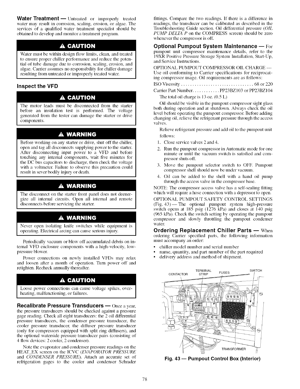
Water Treatment--Untreated or improperly treated
water may result in corrosion, scaling, erosion, or algae. The
services of a qu_dified water treatment specialist should be
obtained to develop and monitor a treatment program.
Water must be within design flow limits, clean, and treated
to ensure proper chiller performance and reduce the poten-
tial of tube &image due to corrosion, scaling, erosion, and
algae. CtuTier assumes no responsibility for chiller &image
resulting from untreated or improperly treated watec
Inspect the VFD
The motor leads must be disconnected from the starter
before an insulation test is performed. The voltage
generated from the tester can &_mage the starter o1 drive
components.
Before working on tiny st_uter or drive, shut off the chillel:
open and tag all disconnects supplying power to the stfulec
After disconnecting input power to a VFD and before
touching tiny internal components, wait five minutes for
the DC bus capacitors to discharge, then check the voltage
with a voltmetel: Failure to observe this precaution could
result in sever bodily injury or death.
The disconnect on the st_uter fiont panel does not deener-
gize all internal circuits. Open all internal and remote
disconnects before servicing the sttutel:
Never open isolating knife switches while equipment is
operating. Electrical arcing can cause serious injury.
Periodically vacuum or blow off accumulated debris on in-
ternal VFD enclosure components with a high-velocity, low-
pressure blowec
Power connections on newly installed VFDs may relax
and loosen after a month of operation. Turn power off and
retighten. Recheck annually thereafter.
Loose power connections can cause voltage spikes, over-
heating, m¢fllimctioning, or failures.
Recalibrate Pressure Transducers -- Once a yea1,
the pressure transducers should be checked against a pressure
gage reading. Check all eight transducers: the 2 oil differenti_fl
pressure transduco_, the condenser pressure transducer, the
cooler pressure transduce1: the diffuser pressure transducer
(only for compressors equipped with split ring diffusers), and
the optional wato_ide pressure transducer pairs (consisting of
4 flow devices: 2 cooler. 2 condenser).
Note the evaporator and condenser pressure readings on the
HEAT EX screen on the ICVC (EVAPORATOR PRESSURE
and CONDENSER PRESSURE). Attach an accurate set of
refrigeration gages to the cooler and condenser Schmder
fittings. Comptue the two readings. If there is a difference in
readings, the transducer can be calibrated as described in the
Troubleshooting Guide section. Oil differential pressure (OIL
PUMP DELTA P on the COMPRESS screen) should be zero
whenever the compressor is off.
Optional Pumpout System Maintenance -- For
pumpout unit colnpressor maintenance details, refer to the
19XR Positive Pressure Stolage System Installation, Start-Up,
and Service Instructions.
OPTIONAL PUMPOUT COMPRESSOR OIL CHARGE --
Use oil conforming to Carrier specifications for reciprocat-
ing compressor usage. Oil requirements are as follows:
ISO Viscosity ................................ 68 or 220
Cturier Pfut Number. ........... PP23BZ 103 or PP23BZ104
The total oil chtuge is 13 oz. (0.5 L)
Oil should be visible in the pumpout compressor sight glass
both during operation and at shutdown. Always check the oil
level before operating the pumpout compressol: Before adding
changing oil, relieve the refrigerant pressure through the access
valves.
Relieve refrigerant pressure and add oil to the pumpout unit
follows:
1. Close service v_dves 2and4.
2. Run the pumpout compressor in Automatic mode for one
minute or until the vacuum switch is satisfied and com-
pressor shuts off.
3. Move the pumpout selector switch to OFE Pumpout
compressor shell should now be under vacuum.
4. Oil can be added to the shell with a hand oil pump
through the access valve in the compressor base.
NOTE: The compressor access valve has a self-sealing fitting
which will require a hose connection with a depressor to open.
OPTIONAL PUMPOUT SAFETY CONTROL SETTINGS
(Fig. 43)--The optional pumpout system high-pressure
switch opens fit 185 psig (1276 kPa) and closes fit 140 psig
(965 kPa). Check the switch setting by operating the pumpout
compressor and slowly throttling the pumpout condenser
water
Ordering Replacement Chiller Parts -- When
ordering Carrier specified parts, the following information
must accompany tin order:
• chiller model number and serial number
• name, quantity, and part number of the part required
• delivery address and method of shipment.
TERMINAL
CONTACTOR STRIP FUSES
\
SWITCH
@
TRANSFORMER
Fig. 43 -- Pumpout Control Box (Interior)
78
TROUBLESHOOTING GUIDE
(Tables 15-18B)
Overview- The PIC III has many features to help tile
operator and technician troubleshoot a 19XRV chiller
• The ICVC shows the chiller's actual operating condi-
tions and can be viewed while the unit is running.
• The ICVC default screen freezes when an alarm occurs.
The freeze enables the operator to view the chiller condi-
tions at the time of alarm. The STATUS screens continue
to show current information. Once all alarms have been
cleared (by correcting the problems and pressing the
softkey), the ICVC default screen returns to
normal operation.
• The CONTROL ALGORITHM STATUS screens (which
include the CAPACITY. OVERRIDE, LL_MAINT.
VFD_HIST. LOADSHED, CUR_ALARM, WSM-
DEFME, and OCCDEFCM screens) display information
that helps to diagnose problems with chilled water
temperature control, chilled water temperature control
overrides, hot gas bypass, surge algorithm status, and
time schedule operation. See Table 15.
• The control test feature facilitates the proper operation
and test of temperature sensors, pressure transducers, the
guide vane actuator, oil pump, water pumps, tower
control, and other on/off outputs while the compressor is
stopped. It also has the ability to lock off the compressor
and turn on water pumps for pumpout operation. The
ICVC shows the temperatures and pressures required
during these operations.
• From other SERVICE tables, the operator/technician can
access configured items, such as chilled water resets,
override set points, etc.
• If an operating fault is detected, an alarm message is gen-
erated and displayed on the ICVC default screen. A more
detailed message -- along with a diagnostic message --
is also stored into the ALARM HISTORY and ALERT
H[STORY tables.
• Review the ALERT HISTORY table to view other less
critical events and abnormal conditions which may have
occurred. Compare timing of relevant alerts and alarms.
Checking Display Messages--The first area to
check when troubleshooting the 19XRV is the ICVC display. If
the alarm light is flashing, check the primary and secon&wy
message lines on the ICVC default screen (Fig. 14). These
messages will indicate where the fault is occurring. These
messages contain the alarm message with a specified code.
This code or state appears with each alarln and alert message.
The ALARM and ALERT HISTORY tables on the [CVC
SERVICE menu also contains a message to further expand on
the fault description.
NOTE: The &_te format in these tables is MM/DD/YY.
For a complete list of possible _darm and alert messages, see
Table 15. If the alarm light starts to flash while accessing a
menu screen, press the _ softkey to return to the defimlt
screen to read the almm message. The STATUS screen can also
be accessed to determine where an alarm exists.
A "C" to the right ofa pammeter's value means that there is
a communications fault on that channel.
Checking Temperature Sensors --All temperature
sensors are thermistor-type sensors. This means that the
resistance of the sensor varies with temperature. All sensors
have the same resistance characteristics. If the controls m'e on,
determine sensor temperature by measuring voltage diop; if the
controls are powered off, detemfine sensor temperature by
measuring resistance. Compare the readings to the values listed
in Table 18A or 18B.
RESISTANCE CHECK -- Turn off the control power and,
fi_)m the module, disconnect the terminal plug of the sensor in
question. With a digital ohmmetel: measure sensor resistance
between receptacles as designated by the wiring diagram. The
resistance and corresponding temperature are listed in
Table 18A or 18B. Check the resistance of both wires to
ground. This resistance should be infinite.
VOLTAGE DROP -- The voltage drop across any energized
sensor can be measured with a digital voltmeter while the
control is energized. Table 18A or 18B lists the relationship
between temperature and sensor voltage drop (volts dc
measmed across the energized sensor). Exercise ctue when
measuring voltage to prevent damage to the sensor leads,
connector plugs, and modules. Sensors should also be checked
at the sensor plugs. Check the sensor wire at the sensor for
5 vdc if the control is powered on.
Relieve all refrigerant pressure or &'ain the water before
replacing temperature sensors or thermowells threaded into
the refrigerant pressure boundary. Failure to do so could
result in persomd injmy and equipment damage.
CHECK SENSOR ACCURACY-- Place the sensor in a
medium of known temperature and compare that temperatme
to the measured reading. The thermometer used to determine
the temperature of the medium should be of laboratory qu_flity
with 0.5 ° F (.25 ° C) graduations. The sensor in question should
be accurate to within 2 ° F (1.2 ° C).
See Fig. 7 for sensor locations. The sensors are immersed
directly in the refrigerant or water circuits. The wiring at each
sensor is easily disconnected by unlatching the connectol:
These connectors allow only one-way connection to the sensol:
When installing a new sensor, apply a pipe sealant or thread
sealant to the sensor threads.
DUAL TEMPERATURE SENSORS -- For servicing con-
venience, there are 2 sensol_ each on the beming and motor
temperature sensors. If one of the sensors is &_maged, the other
can be used by simply moving a wire. The number 2 terminal
in the sensor terminal box is the common line. To use the
second sensol: move the wire from the number I position to the
number 3 position.
Checking Pressure Transducers-- There are 6
factoly-installed pressure transducers, with inputs available for
optional cooler and condenser watel.side differential pressure
transducers. The ICVC softwm'e will display a default reading
of 26 psi during start-up and operation. An additional transduc-
er. factory inst;_lled in the bottom of the cooler barrel, will read
as EVAPORATOR SATURATION TEMP on the HEAT_EX
DISPLAY screen. This provides additional protection against a
loss of water flow condition.
These pressure transducers can be calibrated if necessary. It
is not usually necessary to calibrate at initial start-up.
However. at high altitude locations, it is necessmy to calibrate
the transducel.'s to ensure the proper refrigerant temperature/
pressure relationship. Each transducer is supplied with 5 vdc
power from the CCM. If the power supply fifils, a transducer
voltage reference alarm occurs. If the transducer reading is
suspected of being faulty, check the TRANSDUCER VOLT-
AGE REF supply voltage. It should be 5 vdc _+.5v displayed in
CONTROL TEST under CCM PRESSURE TRANSDUC-
ERS. If the TRANSDUCER VOLTAGE REF is correct, the
transducer should be recalibrated or replaced.
Also check that inputs on CCM J5-1 through J5-6 have not
been grounded and are not receiving anything other than a 4 to
20 mA signal.
79
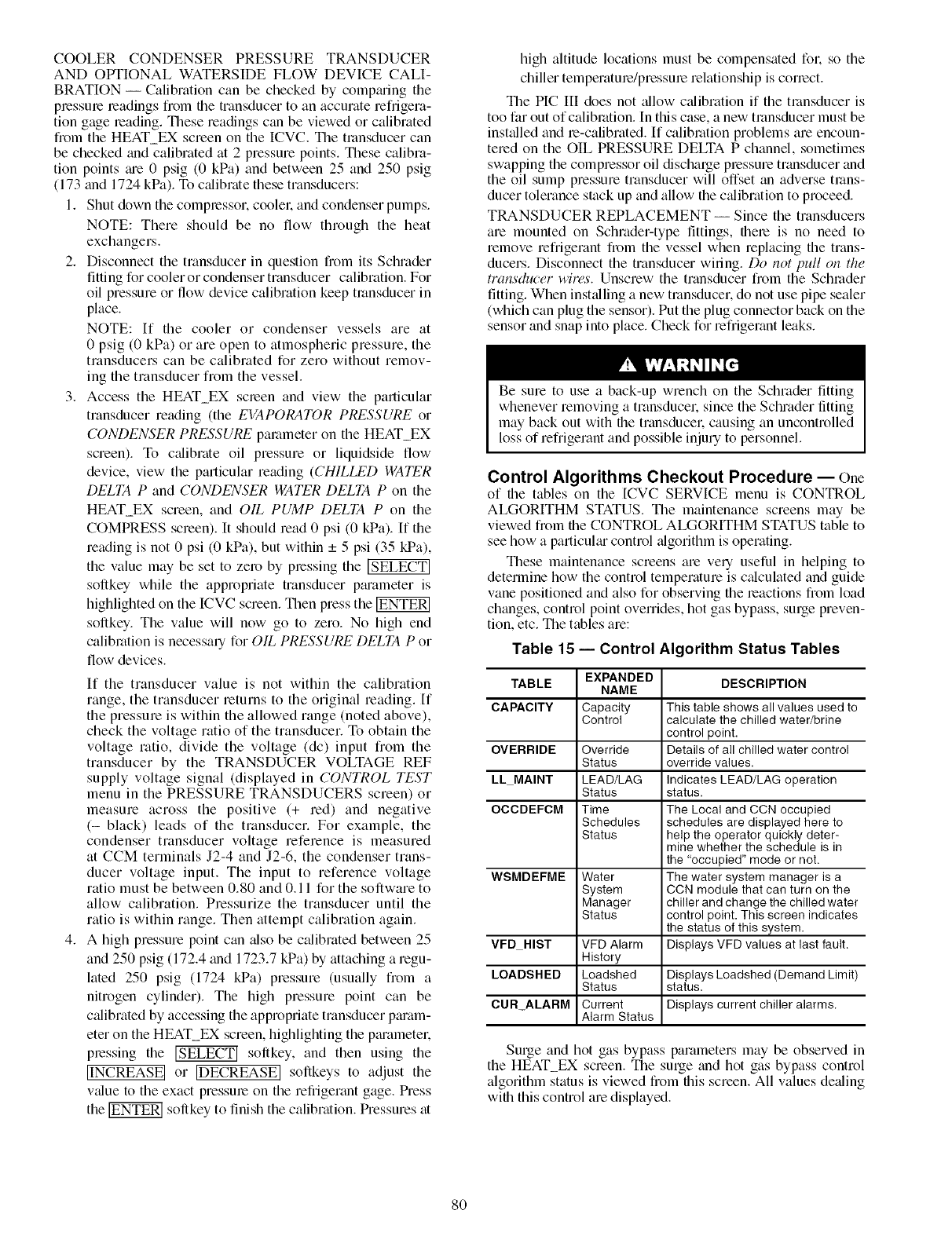
COOLER CONDENSER PRESSURE TRANSDUCER
AND OPTIONAL WATERSIDE FLOW DEVICE CALI-
BRATION -- Calibration can be checked by compming the
plessme leadings from file transducer to an accurate refrigera-
tion gage leading. These readings can be viewed or calibrated
from the HEAT_EX screen on the ICVC. The transducer can
be checked grad calibrated fit 2 pressure points. These calibra-
tion points me 0 psig (0 kPa) and between 25 and 250 psig
(173 and 1724 kPa). To calibrate these transducers:
1. Shut down the compressor, coolek and condenser pumps.
NOTE: There should be no flow through the heat
exchangers.
2. Disconnect the transducer in question from its Schmder
fitting for cooler or condenser transducer calibration. For
oil pressure or flow device calibration keep transducer in
place.
NOTE: If the cooler or condenser vessels are at
0 psig (0 kPa) or are open to atmospheric pressure, the
transducers can be calibrated for zero without remov-
ing the transducer from the vessel.
3. Access the HEAT_EX scleen and view the particular
transducer reading (the EVAPORATOR PRESSURE or
CONDENSER PRESSURE parameter on the HEAT EX
screen). To calibrate oil pressure or liquidside flow
device, view the particular reading (CHILLED WATER
DELTA P and CONDENSER WATER DELTA P on the
HEAT_EX screen, and OIL PUMP DELTA P on the
COMPRESS screen). It should read 0 psi (0 kPa). If the
reading is not 0 psi (0 kPa), but within _+5 psi (35 kPa),
the value may be set to zero by pressing the
softkey while the appropriate transducer ptuameter is
highlighted on the ICVC screen. Then press the
softkey. The value will now go to zero. No high end
calibration is necessary for OIL PRESSURE DELTA P or
flow devices.
If the transducer value is not within the calibration
range, the transducer returns to the original reading. If
the pressure is within the allowed range (noted above),
check the voltage ratio of the transducer. To obtain the
voltage ratio, divide the voltage (dc) input from the
transducer by the TRANSDUCER VOLTAGE REF
supply voltage signal (displayed in CONTROL TEST
menu in the PRESSURE TRANSDUCERS screen) or
measure across the positive (+ red) and negative
(- black) leads of the transducer. For example, the
condenser transducer voltage reference is measured
fit CCM terminals J2-4 and J2-6, the condenser trans-
ducer voltage input. The input to reference voltage
ratio must be between 0.80 and 0.11 for the software to
allow calibration. Pressurize the transducer until the
ratio is within range. Then attempt calibration again.
4. A high pressure point can fdso be calibrated between 25
and 250 psig (172.4 and 1723.7 kPa) by attaching a regu-
lated 250 psig (1724 kPa) pressure (usually from a
nitrogen cylinder). The high pressure point can be
calibrated by accessing the appropriate transducer pmam-
eter on the HEAT_EX screen, highlighting the pm'ametek
pressing the _ softkey, and then using the
[INCREASE 1 or [DECREASE] softkeys to adjust the
vfdue to the exact pressure on the refrigerant gage. Press
the _ softkey to finish the calibration. Pressures fit
high altitude locations must be compensated fok so the
chiller temperature/pressure relationship is correct.
The PIC III does not allow calibration if the transducer is
too far out of calibration. In this case, a new transducer must be
installed and re-calibrated. If calibration problems are encoun-
tered on the OIL PRESSURE DELTA P channel, sometimes
swapping the compressor oil discharge pressure transducer and
the oil sump pressure transducer will offset an adverse trans-
ducer tolerance stack up and allow the calibration to proceed.
TRANSDUCER REPLACEMENT -- Since the transducers
are mounted on Schrader-type fittings, there is no need to
remove refrigerant from the vessel when replacing the trans-
ducers. Disconnect the transducer winng. Do not pull on the
transducer wires. Unscrew the transducer from the Schmder
fitting. When instfdling a new transducer, do not use pipe sealer
(which can plug the sensor). Put the plug connector back on the
sensor and snap into place. Check for refi'igerant leaks.
Be sure to use a back-up wrench on the Schrader fitting
whenever removing a transducek since the Schmder fitting
may back out with the transducek causing an uncontrolled
loss of refrigerant and possible injury to personnel.
Control Algorithms Checkout Procedure -- One
of the tables on the [CVC SERVICE menu is CONTROL
ALGORITHM STATUS. The maintenance screens may be
viewed from the CONTROL ALGORITHM STATUS table to
see how a particulm control algorithm is operating.
These maintenance screens are very useful in helping to
determine how the control temperature is calculated and guide
vane positioned and also for observing the leactions from load
changes, control point overrides, hot gas bypass, surge preven-
tion, etc. The tables are:
Table 15- Control Algorithm Status Tables
TABLE EXPANDED DESCRIPTION
NAME
CAPACITY Capacity This tableshows all values used to
Control calculate the chilled water/brine
control point.
OVERRIDE Override Details of all chilled water control
Status overridevalues.
LL MAINT LEAD/LAG Indicates LEAD/LAG operation
Status status.
OCCDEFCM Time The Local and CCN occupied
Schedules schedules are displayedhere to
Status help the operator quickly deter-
mine whether the schedule is in
the "occupied" mode or not.
WSMDEFME Water The water system manager is a
System CCN module that can turn on the
Manager chiller and change the chilled water
Status control point, This screen indicates
the status of this system.
VFD HIST VFD Alarm Displays VFD values at last fault.
History
LOADSHED Loadshed DisplaysLeadshed (Demand Limit)
Status status.
CURALARM Current Displays current chiller alarms.
Alarm Status
Surge and hot gas bypass parameters may be observed in
the HEAT_EX screen. The surge and hot gas bypass control
algorithm status is viewed from tiffs screen. All values defiling
wifll this control are displayed.
8O
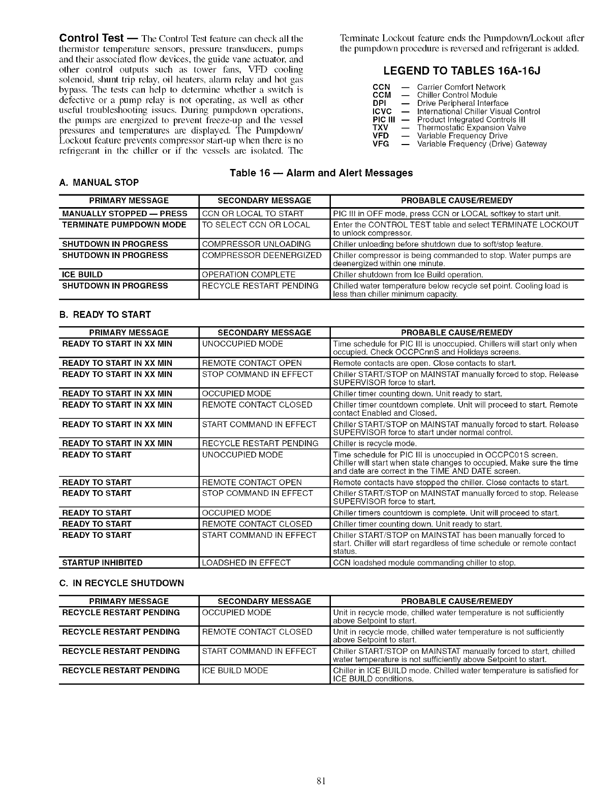
Control Test -- The Control Test feature can check all the
thermistor temperature sensors, pressure transducel_, pumps
and their associated flow devices, the guide vane actuatol: and
other control outputs such as tower fans, VFD cooling
solenoid, shunt trip relay, oil heaters, alarm relay and hot gas
bypass. The tests can help to determine whether a switch is
defective or a pump relay is not operating, as well as other
useful n_ubleshooting issues. During pumpdown operations,
the pumps _ue energized to prevent fieeze-up and the vessel
pressures and temperatures ale displayed. The Pumpdown/
Lockout feature prevents compressor start-up when there is no
refiigerant in the chiller or if the vessels are isolated. The
Terminate Lockout feature ends the Pumpdown/Lockout after
the pumpdown procedure is reversed and refrigerant is added.
LEGEND TO TABLES 16A-16J
CCN --
CCM --
DPI --
ICVC --
PIC III --
TXV --
VFD --
VFG --
Carrier Comfort Network
Chiller Control Module
Drive Peripheral Interface
International Chiller Visual Control
Product Integrated Controls III
Thermostatic Expansion Valve
Variable Frequency Drive
Variable Frequency (Drive) Gateway
A. MANUAL STOP Table 16 -- Alarm and Alert Messages
PRIMARY MESSAGE SECONDARY MESSAGE PROBABLE CAUSE/REMEDY
MANUALLY STOPPED -- PRESS CCN OR LOCAL TO START PIC III in OFF mode, press CCN or LOCAL softkey to start unit.
TERMINATE PUMPDOWN MODE TO SELECT CCN OR LOCAL Enter the CONTROL TEST table and select TERMINATE LOCKOUT
to unlock compressor.
SHUTDOWN IN PROGRESS COMPRESSOR UNLOADING Chiller unloading before shutdown due to soft!stop feature.
SHUTDOWN IN PROGRESS COMPRESSOR DEENERGIZED Chiller compressor is being commanded to stop. Water pumps are
deenergized within one minute.
ICE BUILD OPERATION COMPLETE Chiller shutdown from Ice Build operation.
SHUTDOWN IN PROGRESS RECYCLE RESTART PENDING Chilled water temperature below recycle set point. Cooling load is
less than chiller minimum capacity.
B. READY TO START
PRIMARY MESSAGE SECONDARY MESSAGE PROBABLE CAUSE/REMEDY
READY TO START IN XX MIN UNOCCUPIED MODE Time schedule for PIC III is unoccupied. Chillers will start only when
occupied. Check OCCPCnnS and Holidays screens.
READY TO START IN XX MIN REMOTE CONTACT OPEN Remote contacts are open. Close contacts to start.
READY TO START IN XX MIN STOP COMMAND IN EFFECT Chiller START/STOP on MAINSTAT manually forced to stop. Release
SUPERVISOR force to start.
READY TO START IN XX MIN OCCUPIED MODE Chiller timer counting down. Unit ready to start.
READY TO START IN XX MIN REMOTE CONTACT CLOSED Chiller timer countdown complete. Unit will proceed to start. Remote
contact Enabled and Closed.
READY TO START IN XX MIN START COMMAND IN EFFECT Chiller START/STOP on MAINSTAT manually forced to start. Release
SUPERVISOR force to start under normal control.
READY TO START IN XX MIN RECYCLE RESTART PENDING Chiller is recycle mode.
READY TO START UNOCCUPIED MODE Time schedule for PIC III is unoccupied in OCCPC01S screen.
Chiller will start when state changes to occupied. Make sure the time
and date are correct in the TIME AND DATE screen.
READY TO START REMOTE CONTACT OPEN Remote contacts have stopped the chiller. Close contacts to start.
READY TO START STOP COMMAND IN EFFECT Chiller START/STOP on MAINSTAT manually forced to stop. Release
SUPERVISOR force to start.
READY TO START OCCUPIED MODE Chiller timers countdown is complete. Unit will proceed to start.
READY TO START REMOTE CONTACT CLOSED Chiller timer counting down. Unit ready to start.
READY TO START START COMMAND IN EFFECT Chiller START/STOP on MAINSTAT has been manually forced to
start. Chiller will start regardless of time schedule or remote contact
status.
STARTUP INHIBITED LOADSHED IN EFFECT CCN Ioadshed module commanding chiller to stop.
C. IN RECYCLE SHUTDOWN
PRIMARY MESSAGE SECONDARY MESSAGE PROBABLE CAUSE/REMEDY
RECYCLE RESTART PENDING OCCUPIED MODE Unit in recycle mode, chilled water temperature is not sufficiently
above Setpoint to start.
RECYCLE RESTART PENDING REMOTE CONTACT CLOSED Unit in recycle mode, chilled water temperature is not sufficiently
above Setpoint to start.
RECYCLE RESTART PENDING START COMMAND IN EFFECT Chiller START/STOP on MAINSTAT manually forced to start, chilled
water temperature is not sufficiently above Setpoint to start.
RECYCLE RESTART PENDING ICE BUILD MODE Chiller in ICE BUILD mode. Chilled water temperature is satisfied for
ICE BUILD conditions.
81
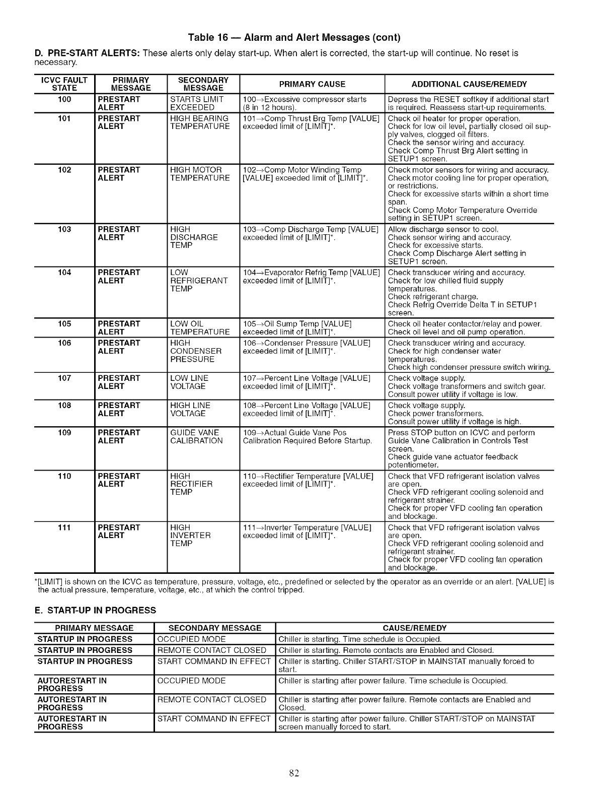
Table 16 -- Alarm and Alert Messages (cont)
D. PRE-START ALERTS: These alerts only delay start-up. When alert is corrected, the start-up will continue. No reset is
necessary.
ICVC FAULT PRIMARY SECONDARY
STATE MESSAGE MESSAGE PRIMARY CAUSE ADDITIONAL CAUSE/REMEDY
100 PRESTART STARTS LIMIT 100_Excessive compressor starts Depress the RESET softkey if additional start
ALERT EXCEEDED (8 in 12 hours), is required. Reassess start-up requirements.
101 PRESTART HIGH BEARING 101_Comp Thrust Brg Temp [VALUE] Check oil heater for proper operation.
ALERT TEMPERATURE exceeded limit of [LIMIT]*. Check for low oil level, partially closed oil sup-
ply valves, clogged oil filters.
Check the sensor wiring and accuracy.
Check Comp Thrust Brg Alert setting in
SETUP1 screen.
102 PRESTART HIGH MOTOR 102-_Comp Motor Winding Temp Check motor sensors for wiring and accuracy.
ALERT TEMPERATURE [VALUE] exceeded limit of [LIMIT]*. Check motor cooling line for proper operation,
or restrictions.
Check for excessive starts within a short time
span.
Check Comp Motor Temperature Override
setting in SETUP1 screen.
103 PRESTART HIGH 103_Comp Discharge Temp [VALUE] Allow discharge sensor to cool.
ALERT DISCHARGE exceeded limit of [LIMIT]*. Check sensor wiring and accuracy.
TEMP Check for excessive starts.
Check Comp Discharge Alert setting in
SETUP1 screen.
104 PRESTART LOW 104-_Evaporator Refrig Temp [VALUE] Check transducer wiring and accuracy.
ALERT REFRIGERANT exceeded limit of [LIMIT]*. Check for low chilled fluid supply
TEMP temperatures.
Check refrigerant charge.
Check Refrig Override Delta T in SETUP1
screen.
105 PRESTART LOW OIL 105_Oil Sump Temp [VALUE] Check oil heater contactor/relay and power.
ALERT TEMPERATURE exceeded limit of [LIMIT]*. Check oil level and oil pump operation.
106 PRESTART HIGH 106_Condenser Pressure [VALUE] Check transducer wiring and accuracy.
ALERT CONDENSER exceeded limit of [LIMIT]*. Check for high condenser water
PRESSURE temperatures.
Check high condenser pressure switch wiring.
107 PRESTART LOW LINE 107-_Percent Line Voltage [VALUE] Check voltage supply.
ALERT VOLTAGE exceeded limit of [LIMIT]*. Check voltage transformers and switch gear.
Consult power utility if voltage is low.
108 PRESTART HIGH LINE 108_Percent Line Voltage [VALUE] Check voltage supply.
ALERT VOLTAGE exceeded limit of [LIMIT]*. Check power transformers.
Consult power utility if voltage is high.
109 PRESTART GUIDE VANE 109_Actual Guide Vane Pos Press STOP button on ICVC and perform
ALERT CALIBRATION Calibration Required Before Startup. Guide Vane Calibration in Controls Test
screen.
Check guide vane actuator feedback
potentiometer.
110 PRESTART HIGH 110_Rectifier Temperature [VALUE] Check that VFD refrigerant isolation valves
ALERT RECTIFIER exceeded limit of [LIMIT]*. are open.
TEMP Check VFD refrigerant cooling solenoid and
refrigerant strainer.
Check for proper VFD cooling fan operation
and blockage.
111 PRESTART HIGH 111-_lnverter Temperature [VALUE] Check that VFD refrigerant isolation valves
ALERT INVERTER exceeded limit of [LIMIT]*. are open.
TEMP Check VFD refrigerant cooling solenoid and
refrigerant strainer.
Check for proper VFD cooling fan operation
and blockage.
*[LIMIT] is shown on the ICVC as temperature, pressure, voltage, etc., predefined or selected by the operator as an override or an alert. [VALUE] is
the actual pressure, temperature, voltage, etc., at which the control tripped.
E. START-UP IN PROGRESS
PRIMARY MESSAGE SECONDARY MESSAGE CAUSE/REMEDY
STARTUP IN PROGRESS OCCUPIED MODE Chiller is starting. Time schedule is Occupied.
STARTUP IN PROGRESS REMOTE CONTACT CLOSED Chiller is starting. Remote contacts are Enabled and Closed.
STARTUP IN PROGRESS START COMMAND IN EFFECT Chiller is starting. Chiller START/STOP in MAINSTAT manually forced to
start.
AUTORESTART IN OCCUPIED MODE Chiller is starting after power failure. Time schedule is Occupied.
PROGRESS
AUTORESTART IN REMOTE CONTACT CLOSED Chiller is starting after power failure. Remote contacts are Enabled and
PROGRESS Closed.
AUTORESTART IN START COMMAND IN EFFECT Chiller is starting after power failure. Chiller START/STOP on MAINSTAT
PROGRESS screen manually forced to start.
82
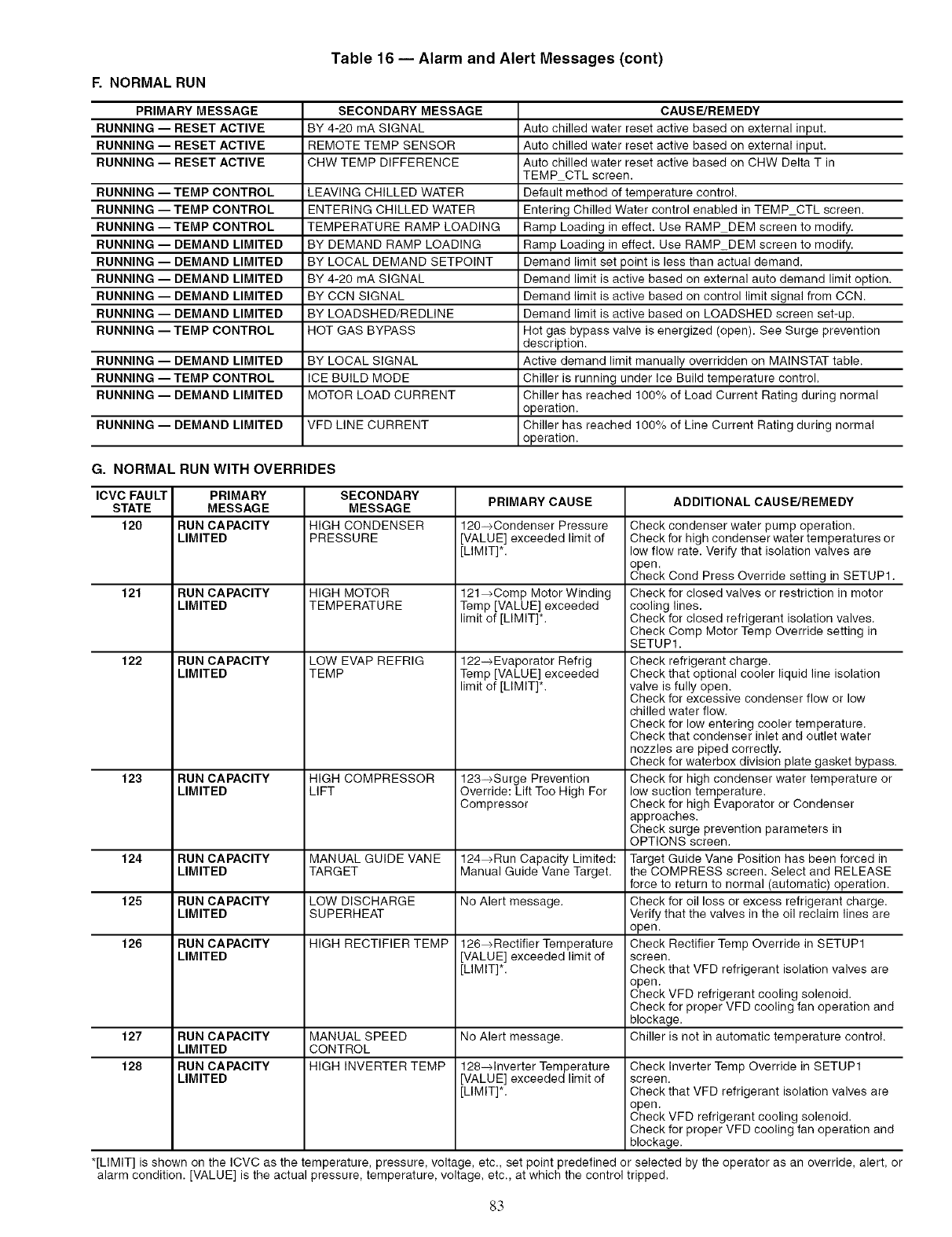
R NORMALRUN
Table 16 -- Alarm and Alert Messages (cont)
PRIMARY MESSAGE SECONDARY MESSAGE CAUSE]REMEDY
RUNNING -- RESET ACTIVE BY 4-20 mA SIGNAL Auto chilled water reset active based on external input.
RUNNING -- RESET ACTIVE REMOTE TEMP SENSOR Auto chilled water reset active based on external input.
RUNNING -- RESET ACTIVE CHW TEMP DIFFERENCE Auto chilled water reset active based on CHW Delta T in
TEMP CTL screen.
RUNNING -- TEMP CONTROL LEAVING CHILLED WATER Default method of temperature control.
RUNNING -- TEMP CONTROL ENTERING CHILLED WATER Entering Chilled Water control enabled in TEMP CTL screen.
RUNNING -- TEMP CONTROL TEMPERATURE RAMP LOADING Ramp Loading in effect. Use RAMP DEM screen to modify.
RUNNING -- DEMAND LIMITED BY DEMAND RAMP LOADING Ramp Loading in effect. Use RAMP DEM screen to modify.
RUNNING -- DEMAND LIMITED BY LOCAL DEMAND SETPOINT Demand limit set point is less than actual demand.
RUNNING -- DEMAND LIMITED BY 4-20 mA SIGNAL Demand limit is active based on external auto demand limit option.
RUNNING -- DEMAND LIMITED BY CCN SIGNAL Demand limit is active based on control limit signal from CCN.
RUNNING -- DEMAND LIMITED BY LOADSHED/REDLINE Demand limit is active based on LOADSHED screen set-up.
RUNNING -- TEMP CONTROL HOT GAS BYPASS Hot gas bypass valve is energized (open). See Surge prevention
description.
RUNNING -- DEMAND LIMITED BY LOCAL SIGNAL Active demand limit manually overridden on MAINSTAT table.
RUNNING -- TEMP CONTROL ICE BUILD MODE Chiller is running under Ice Build temperature control.
RUNNING -- DEMAND LIMITED MOTOR LOAD CURRENT Chiller has reached 100% of Load Current Rating during normal
operation.
RUNNING -- DEMAND LIMITED VFD LINE CURRENT Chiller has reached 100% of Line Current Rating during normal
operation.
G. NORMAL RUN WITH OVERRIDES
ICVC FAULT PRIMARY SECONDARY PRIMARY CAUSE ADDITIONAL CAUSE]REMEDY
STATE MESSAGE MESSAGE
120 RUN CAPACITY HIGH CONDENSER 120-_Condenser Pressure
LIMITED PRESSURE [VALUE] exceeded limit of
[LIMIT]*.
121 RUN CAPACITY HIGH MOTOR 121_Comp Motor Winding
LIMITED TEMPERATURE Temp [VALUE] exceeded
limit of [LIMIT]*.
122 RUN CAPACITY
LIMITED
LOW EVAP REFRIG
TEMP 122_-_Evaporator Refrig
Temp [VALUE] exceeded
limit of [LIMIT]*.
123 RUN CAPACITY HIGH COMPRESSOR 123-_Surge Prevention
LIMITED LIFT Override: Lift Too High For
Compressor
124 RUN CAPACITY MANUAL GUIDE VANE 124_Run Capacity Limited:
LIMITED TARGET Manual Guide Vane Target.
125 RUN CAPACITY LOW DISCHARGE No Alert message.
LIMITED SUPERHEAT
126 RUN CAPACITY HIGH RECTIFIER TEMP 126_Rectifier Temperature
LIMITED [VALUE] exceeded limit of
[LIMIT]*.
Check condenser water pump operation.
Check for high condenser water temperatures or
low flow rate. Verify that isolation valves are
open.
Check Cond Press Override setting in SETUP1.
Check for closed valves or restriction in motor
cooling lines.
Check for closed refrigerant isolation valves.
Check Comp Motor Temp Override setting in
SETUP1.
Check refrigerant charge.
Check that optional cooler liquid line isolation
valve is fully open.
Check for excessive condenser flow or low
chilled water flow.
Check for low entering cooler temperature.
Check that condenser inlet and outlet water
nozzles are piped correctly.
Check for waterbox division plate gasket bypass.
Check for high condenser water temperature or
low suction temperature.
Check for high Evaporator or Condenser
approaches.
Check surge prevention parameters in
OPTIONS screen.
Target Guide Vane Position has been forced in
the COMPRESS screen. Select and RELEASE
force to return to normal (automatic) operation.
Check for oil loss or excess refrigerant charge.
Verify that the valves in the oil reclaim lines are
open.
Check Rectifier Temp Override in SETUP1
screen.
Check that VFD refrigerant isolation valves are
open.
Check VFD refrigerant cooling solenoid.
Check for proper VFD cooling fan operation and
blockage.
Chiller is not in automatic temperature control.127 RUN CAPACITY MANUAL SPEED No Alert message.
LIMITED CONTROL
128 RUN CAPACITY HIGH INVERTER TEMP 128-qnverter Temperature Check Inverter Temp Override in SETUP1
LIMITED [VALUE] exceeded limit of screen.
[LIMIT]*. Check that VFD refrigerant isolation valves are
open.
Check VFD refrigerant cooling solenoid.
Check for proper VFD cooling fan operation and
blockage.
*[LIMIT] is shown on the ICVC as the temperature, pressure, voltage, etc., set point predefined or selected by the operator as an override, alert, or
alarm condition. [VALUE] is the actual pressure, temperature, voltage, etc., at which the control tripped.
8.3
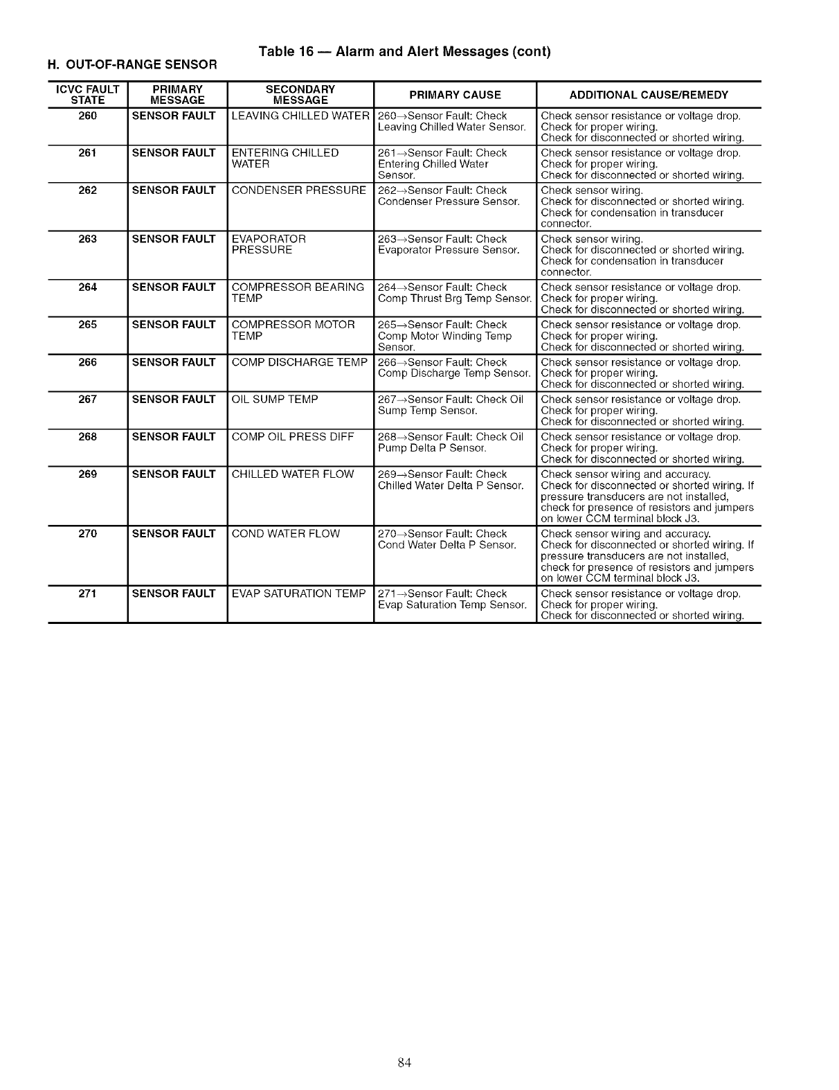
Table 16 -- Alarm and Alert Messages (cont)
H. OUT-OF-RANGE SENSOR
ICVC FAULT PRIMARY SECONDARY
STATE MESSAGE MESSAGE PRIMARY CAUSE ADDITIONAL CAUSE/REMEDY
260 SENSOR FAULT LEAVING CHILLED WATER 260-+Sensor Fault: Check Check sensor resistance or voltage drop.
Leaving Chilled Water Sensor. Check for proper wiring.
Check for disconnected or shorted wiring.
261 SENSOR FAULT ENTERING CHILLED 261 -+Sensor Fault: Check Check sensor resistance or voltage drop.
WATER Entering Chilled Water Check for proper wiring.
Sensor. Check for disconnected or shorted wiring.
262 SENSOR FAULT CONDENSER PRESSURE 262-+Sensor Fault: Check Check sensor wiring.
Condenser Pressure Sensor. Check for disconnected or shorted wiring.
Check for condensation in transducer
connector.
263 SENSOR FAULT EVAPORATOR 263-+Sensor Fault: Check Check sensor wiring.
PRESSURE Evaporator Pressure Sensor. Check for disconnected or shorted wiring.
Check for condensation in transducer
connector.
264 SENSOR FAULT COMPRESSOR BEARING 264-+Sensor Fault: Check Check sensor resistance or voltage drop.
TEMP Comp Thrust Brg Temp Sensor. Check for proper wiring.
Check for disconnected or shorted wiring.
265 SENSOR FAULT COMPRESSOR MOTOR 265-+Sensor Fault: Check Check sensor resistance or voltage drop.
TEMP Comp Motor Winding Temp Check for proper wiring.
Sensor. Check for disconnected or shorted wiring.
266 SENSOR FAULT COMP DISCHARGE TEMP 266-+Sensor Fault: Check Check sensor resistance or voltage drop.
Comp Discharge Temp Sensor. Check for proper wiring.
Check for disconnected or shorted wiring.
267 SENSOR FAULT OIL SUMP TEMP 267-+Sensor Fault: Check Oil Check sensor resistance or voltage drop.
Sump Temp Sensor. Check for proper wiring.
Check for disconnected or shorted wiring.
268 SENSOR FAULT COMP OIL PRESS DIFF 268-+Sensor Fault: Check Oil Check sensor resistance or voltage drop.
Pump Delta P Sensor. Check for proper wiring.
Check for disconnected or shorted wiring.
269 SENSOR FAULT CHILLED WATER FLOW 269-+Sensor Fault: Check Check sensor wiring and accuracy.
Chilled Water Delta P Sensor. Check for disconnected or shorted wiring. If
3ressure transducers are not installed,
check for presence of resistors and jumpers
on lower CCM terminal block J3.
270 SENSOR FAULT COND WATER FLOW 270-+Sensor Fault: Check Check sensor wiring and accuracy.
Cond Water Delta P Sensor. Check for disconnected or shorted wiring. If
3ressure transducers are not installed,
check for presence of resistors and jumpers
on lower CCM terminal block J3.
271 SENSOR FAULT EVAP SATURATION TEMP 271-+Sensor Fault: Check Check sensor resistance or voltage drop.
Evap Saturation Temp Sensor. Check for proper wiring.
Check for disconnected or shorted wiring.
84
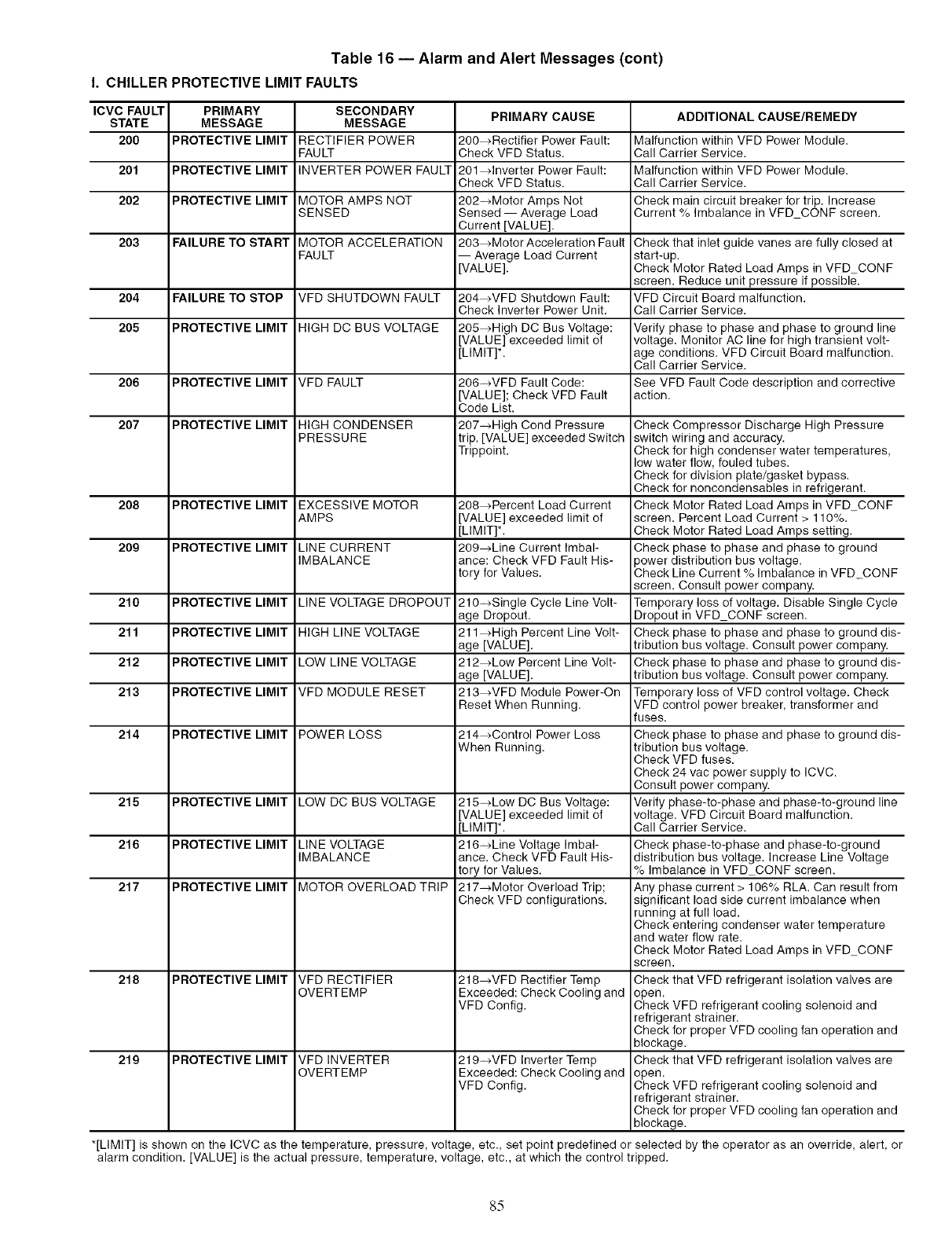
Table 16 -- Alarm and Alert Messages (cent)
I. CHILLER PROTECTIVE LIMIT FAULTS
ICVC FAULT PRIMARY SECONDARY PRIMARY CAUSE ADDITIONAL CAUSE/REMEDY
STATE MESSAGE MESSAGE
200 PROTECTIVE LIMIT RECTIFIER POWER 200_Rectifier Power Fault: Malfunction within VFD Power Module.
FAULT Check VFD Status. Call Carrier Service.
201 PROTECTIVE LIMIT INVERTER POWER FAULT 201_lnverter Power Fault: Malfunction within VFD Power Module.
Check VFD Status. Call Carrier Service.
202 PROTECTIVE LIMIT MOTOR AMPS NOT 202-_Motor Amps Not Check main circuit breaker for trip. Increase
SENSED Sensed -- Average Load Current % Imbalance in VFD CONF screen.
Current [VALUE].
203 FAILURE TO START MOTOR ACCELERATION 203_Motor Acceleration Fault Check that inlet guide vanes are fully closed at
FAULT -- Average Load Current start-up.
[VALUE]. Check Motor Rated Load Amps in VFD CONF
Reduce unit pressure if possible.screen.
204 FAILURE TO STOP VFD SHUTDOWN FAULT 204_VFD Shutdown Fault: VFD Circuit Board malfunction.
Check Inverter Power Unit. Call Carrier Service.
205 PROTECTIVE LIMIT HIGH DC BUS VOLTAGE 205_High DC Bus Voltage: Verify phase to phase and phase to ground line
[VALUE] exceeded limit of voltage. Monitor AC line for high transient volt-
[LIMIT]*. age conditions. VFD Circuit Board malfunction.
Call Carrier Service.
206 PROTECTIVE LIMIT VFD FAULT 206-_VFD Fault Code: See VFD Fault Code description and corrective
[VALUE]; Check VFD Fault action.
Code List.
207 PROTECTIVE LIMIT HIGH CONDENSER 207-_High Cond Pressure Check Compressor Discharge High Pressure
PRESSURE trip. [VALU E] exceeded Switch switch wiring and accuracy.
Trippoint. Check for high condenser water temperatures,
low water flow, fouled tubes.
Check for division plate/gasket bypass.
Check for noncondensables in refrigerant.
208 PROTECTIVE LIMIT EXCESSIVE MOTOR 208_Percent Load Current Check Motor Rated Load Amps in VFD CONF
AMPS [VALUE] exceeded limit of screen. Percent Load Current > 110%.
[LIMIT]*. Check Motor Rated Load Amps setting.
209 PROTECTIVE LIMIT LINE CURRENT 209_Line Current Imbal- Check phase to phase and phase to ground
IMBALANCE ance: Check VFD Fault His- )ower distribution bus voltage.
tory for Values. Check Line Current % Imbalance in VFD_CONF
screen. Consult power company.
210 PROTECTIVE LIMIT LINE VOLTAGE DROPOUT 210-_Single Cycle Line Volt- Temporary loss of voltage. Disable Single Cycle
age Dropout. Dropout in VFD CONF screen.
211 PROTECTIVE LIMIT HIGH LINE VOLTAGE 211_High Percent Line Volt- Check phase to phase and phase to ground dis-
age [VALUE]. tribution bus voltage. Consult power company.
212 PROTECTIVE LIMIT LOW LINE VOLTAGE 212_Low Percent Line Volt- Check phase to phase and phase to ground dis-
age [VALUE]. tribution bus voltage. Consult power company.
213 PROTECTIVE LIMIT VFD MODULE RESET 213_VFD Module Power-On Temporary loss of VFD control voltage. Check
Reset When Running. VFD control power breaker, transformer and
fuses.
214 PROTECTIVE LIMIT POWER LOSS 214_Control Power Loss Check phase to phase and phase to ground dis-
When Running. tribution bus voltage.
Check VFD fuses.
Check 24 vac power supply to ICVC.
Consult power company.
215 PROTECTIVE LIMIT LOW DC BUS VOLTAGE 215-cLew DC Bus Voltage: Verify phase-to-phase and phase-to-ground line
[VALUE] exceeded limit of voltage. VFD Circuit Board malfunction.
[LIMIT]*. Call Carrier Service.
216 PROTECTIVE LIMIT LINE VOLTAGE 216-_Line Voltage Imbal- Check phase-to-phase and phase-to-ground
IMBALANCE ance. Check VFD Fault His- distribution bus voltage. Increase Line Voltage
tory for Values. % Imbalance in VFD CONF screen.
217 PROTECTIVE LIMIT MOTOR OVERLOAD TRIP 217-+Motor Overload Trip; Any phase current > 106% RLA. Can result from
Check VFD configurations, significant load side current imbalance when
running at full load.
Check entering condenser water temperature
and water flow rate.
Check Motor Rated Load Amps in VFD CONF
screen.
218 PROTECTIVE LIMIT VFD RECTIFIER 218_VFD Rectifier Temp Check that VFD refrigerant isolation valves are
OVERTEMP Exceeded: Check Cooling and open.
VFD Cenfig. Check VFD refrigerant cooling solenoid and
refrigerant strainer.
Check for proper VFD cooling fan operation and
blockage.
219 PROTECTIVE LIMIT VFD INVERTER 219-_VFD Inverter Temp Check that VFD refrigerant isolation valves are
OVERTEMP Exceeded: Check Cooling and open.
VFD Cenfig. Check VFD refrigerant cooling solenoid and
refrigerant strainer.
Check for proper VFD cooling fan operation and
blockage.
*[LIMIT] is shown on the ICVC as the temperature, pressure, voltage, etc., set point predefined or selected by the operator as an override, alert, or
alarm condition. [VALUE] is the actual pressure, temperature, voltage, etc., at which the control tripped.
85
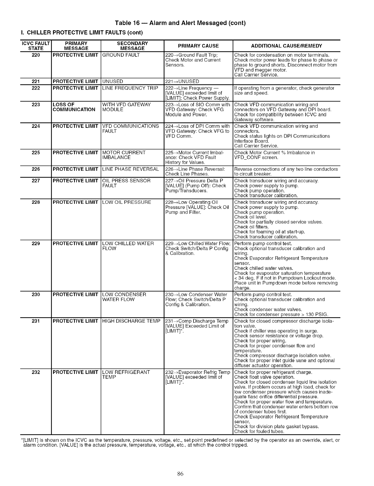
Table 16 -- Alarm and Alert Messaged (cont)
I. CHILLER PROTECTIVE LIMIT FAULTS(cont)
ICVC FAULT PRIMARY SECONDARY PRIMARY CAUSE ADDITIONAL CAUSE/REMEDY
STATE MESSAGE MESSAGE
220 PROTECTIVE LIMIT GROUND FAULT 220-_Ground Fault Trip; Check for condensation on motor terminals.
Check Motor and Current Check motor power leads for phase to phase or
Sensors. phase to ground shorts. Disconnect motor from
VFD and megger motor.
Call Carrier Service.
221 PROTECTIVE LIMIT UNUSED 221_UNUSED
222 PROTECTIVE LIMIT LINE FREQUENCY TRIP 222-_Line Frequency -- If operating from a generator, check generator
[VALUE] exceeded limit of size and speed.
[LIMIT]; Check Power Supply.
223 LOSS OF WITH VFD GATEWAY 223_Loss of SIO Comm with Check VFD communication wiring and
COMMUNICATION MODULE VFD Gateway: Check VFG connectors on VFD Gateway and DPI board.
Module and Power. Check for compatibility between ICVC and
Gateway software.
224 PROTECTIVE LIMIT VFD COMMUNICATIONS 224_Loss of DPI Comm with Check VFD communication wiring and
FAULT VFD Gateway: Check VFG to connectors.
VFD Comm. Check status lights on DPI Communications
Interface Board.
Call Carrier Service.
225 PROTECTIVE LIMIT MOTOR CURRENT 225_Motor Current Imbal- Check Motor Current % Imbalance in
IMBALANCE ance: Check VFD Fault VFD CONF screen.
History for Values.
226 PROTECTIVE LIMIT LINE PHASE REVERSAL 226-_Line Phase Reversal:
Check Line Phases.
227 PROTECTIVE LIMIT OIL PRESS SENSOR 227_Oil Pressure Delta P
FAULT [VALUE] (Pump Off): Check
Pump/Transducers.
228 PROTECTIVE LIMIT LOW OIL PRESSURE
229
230
231
232
PROTECTIVE LIMIT
PROTECTIVE LIMIT
PROTECTIVE LIMIT
PROTECTIVE LIMIT
LOW CHILLED WATER
FLOW
LOW CONDENSER
WATER FLOW
HIGH DISCHARGE TEMP
LOW REFRIGERANT
TEMP
228-_Low Operating Oil
Pressure [VALUE]: Check Oil
Pump and Filter.
229_Low Chilled Water Flow;
Check Switch/Delta P Config
& Calibration.
230-_Low Condenser Water
Flow; Check Switch/Delta P
Config & Calibration.
231_Comp Discharge Temp
[VALUE] Exceeded Limit of
[LIMIT]*.
232_Evaporator Refrig Temp
[VALUE] exceeded limit of
[LIMIT]*.
Reverse connections of any two line conductors
to circuit breaker.
Check transducer wiring and accuracy.
Check power supply to pump.
Check pump operation.
Check transducer calibration.
Check transducer wiring and accuracy.
Check power supply to pump.
Check pump operation.
Check oil level.
Check for partially closed service valves.
Check oil filters.
Check for foaming oil at start-up.
Check transducer calibration.
Perform pump control test.
Check optional transducer calibration and
wiring.
Check Evaporator Refrigerant Temperature
sensor.
Check chilled water valves.
Check for evaporator saturation temperature
< 34 deg. F if not in Pumpdown Lockout mode.
Place unit in Pumpdown mode before removing
charge.
Perform pump control test.
Check optional transducer calibration and
wiring.
Check condenser water valves.
Check for condenser pressure > 130 PSlG.
Check for closed compressor discharge isola-
tion valve.
Check if chiller was operating in surge.
Check sensor resistance or voltage drop.
Check for proper wiring.
Check for proper condenser flow and
temperature.
Check compressor discharge isolation valve.
Check for proper inlet guide vane and optional
diffuser actuator operation.
Check for proper refrigerant charge.
Check float valve operation.
Check for closed condenser liquid line isolation
valve. If problem occurs at high load, check for
low condenser pressure which causes inade-
quate flasc orifice differential pressure.
Check for proper water flow and temperature.
Confirm that condenser water enters bottom row
of condenser tubes first.
Check Evaporator Refrigerant Temperature
sensor.
Check for division plate gasket bypass.
Check for fouled tubes.
*[LIMIT] is shown on the ICVC as the temperature, pressure, voltage, etc., set point predefined or selected by the operator as an override, alert, or
alarm condition. [VALUE] is the actual pressure, temperature, voltage, etc., at which the control tripped.
86
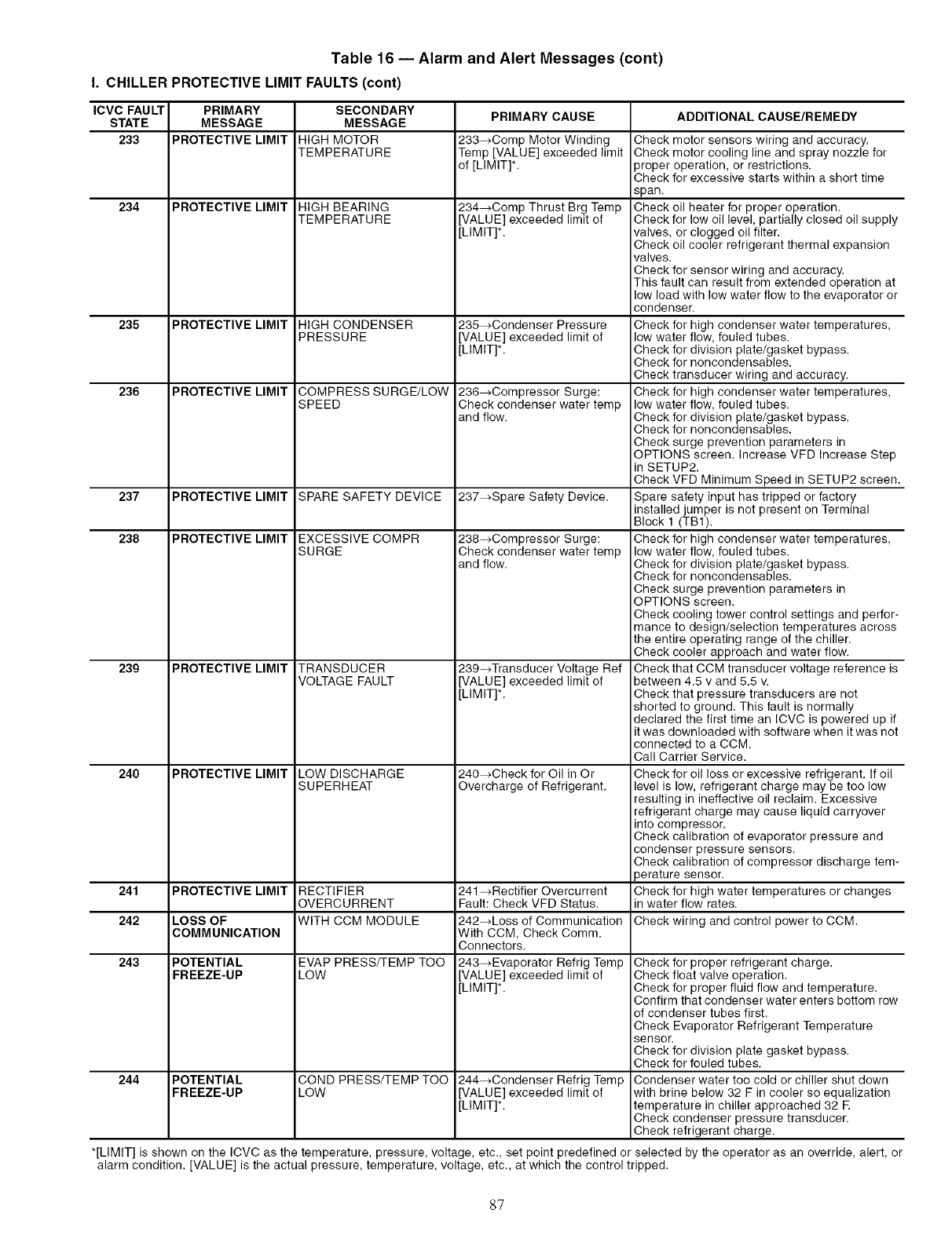
Table 16 -- Alarm and Alert Messages (cent)
I. CHILLER PROTECTIVE LIMIT FAULTS(cent)
ICVC FAULT PRIMARY SECONDARY PRIMARY CAUSE ADDITIONAL CAUSE/REMEDY
STATE MESSAGE MESSAGE
233 PROTECTIVE LIMIT HIGH MOTOR 233->Comp Motor Winding
TEMPERATURE Temp [VALUE] exceeded limit
of [LIMIT]*.
234 PROTECTIVE LIMIT HIGH BEARING
TEMPERATURE
235
236
PROTECTIVE LIMIT
PROTECTIVE LIMIT
HIGH CONDENSER
PRESSURE
COMPRESS SURGE/LOW
SPEED
234_Comp Thrust Brg Temp
[VALUE] exceeded limit of
[LIMIT]*.
235_Condenser Pressure
[VALUE] exceeded limit of
[LIMIT]*.
236_Compressor Surge:
Check condenser water temp
and flow.
237 PROTECTIVE LIMIT SPARE SAFETY DEVICE 237_Spare Safety Device.
238 PROTECTIVE LIMIT EXCESSIVE COMPR
SURGE
239 TRANSDUCER
VOLTAGE FAULT
LOW DISCHARGE
SUPERHEAT
PROTECTIVE LIMIT
PROTECTIVE LIMIT24O
241 PROTECTIVE LIMIT RECTIFIER
OVERCURRENT
242 LOSS OF WITH CCM MODULE
COMMUNICATION
243 POTENTIAL EVAP PRESS/1-EMP TOO
FREEZE-UP LOW
244 POTENTIAL
FREEZE-UP COND PRESS/TEMP TOO
LOW
238->Compressor Surge:
Check condenser water temp
and flow.
239-->Transducer Voltage Ref
[VALUE] exceeded limit of
[LIMIT]*.
240_Check for Oil in Or
Overcharge of Refrigerant.
241 ->Rectifier Overcurrent
Fault: Check VFD Status.
242-_Loss of Communication
With CCM, Check Comm.
Connectors.
243->Evaporator Refrig Temp
[VALUE] exceeded limit of
[LIMIT]*.
244->Condenser Refrig Temp
[VALUE] exceeded limit of
[LIMIT]*.
Check motor sensors wiring and accuracy.
Check motor cooling line and spray nozzle for
proper operation, or restrictions.
Check for excessive starts within a short time
span.
Check oil heater for proper operation.
Check for low oil level, partially closed oil supply
valves, or clogged oil filter.
Check oil cooler refrigerant thermal expansion
valves.
Check for sensor wiring and accuracy.
This fault can result from extended operation at
low load with low water flow to the evaporator or
condenser.
Check for high condenser water temperatures,
low water flow, fouled tubes.
Check for division plate/gasket bypass.
Check for noncondensables.
Check transducer wiring and accuracy.
Check for high condenser water temperatures,
low water flow, fouled tubes.
Check for division plate/gasket bypass.
Check for noncondensables.
Check surge prevention parameters in
OPTIONS screen. Increase VFD Increase Step
in SETUP2.
Check VFD Minimum Speed in SETUP2 screen.
Spare safety input has tripped or factory
installed jumper is not present on Terminal
Block 1 (TB1).
Check for high condenser water temperatures,
low water flow, fouled tubes.
Check for division plate/gasket bypass.
Check for noncondensables.
Check surge prevention parameters in
OPTIONS screen.
Check cooling tower control settings and perfor-
mance to design/selection temperatures across
the entire operating range of the chiller.
Check cooler approach and water flow.
Check that CCM transducer voltage reference is
between 4.5 v and 5.5 v.
Check that pressure transducers are not
shorted to ground. This fault is normally
declared the first time an ICVC is powered up if
it was downloaded with software when it was not
connected to a CCM.
Call Carrier Service.
Check for oil loss or excessive refrigerant. If oil
level is low, refrigerant charge may be too low
resulting in ineffective oil reclaim. Excessive
refrigerant charge may cause liquid carryover
into compressor.
Check calibration of evaporator pressure and
condenser pressure sensors.
Check calibration of compressor discharge tem-
)erature sensor.
Check for high water temperatures or changes
in water flow rates.
Check wiring and control power to CCM.
Check for proper refrigerant charge.
Check float valve operation.
Check for proper fluid flow and temperature.
Confirm that condenser water enters bottom row
of condenser tubes first.
Check Evaporator Refrigerant Temperature
sensor.
Check for division plate gasket bypass.
Check for fouled tubes.
Condenser water too cold or chiller shut down
with brine below 32 F in cooler so equalization
temperature in chiller approached 32 E
Check condenser pressure transducer.
Check refrigerant charge.
*[LIMIT] is shown on the ICVC as the temperature, pressure, voltage, etc., set point predefined or selected by the operator as an override, alert, or
alarm condition. [VALUE] is the actual pressure, temperature, voltage, etc., at which the control tripped.
87
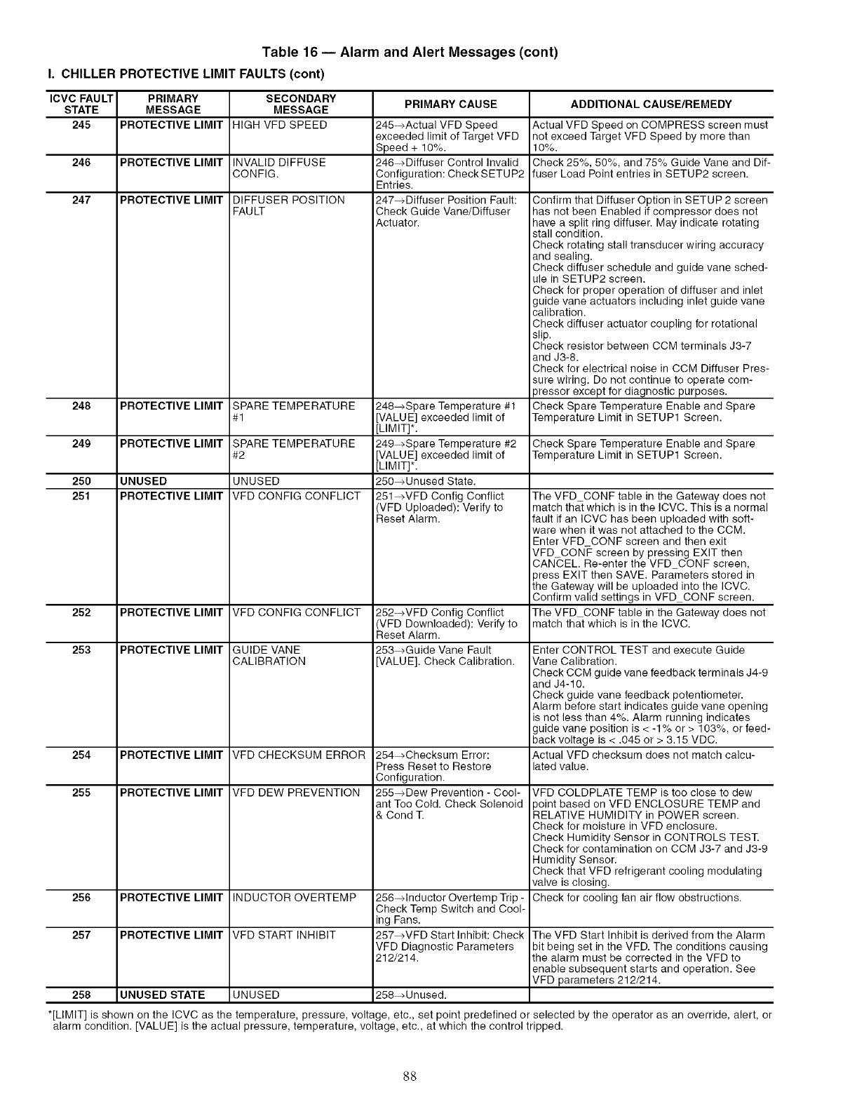
Table 16 -- Alarm and Alert Messages (cont)
I. CHILLER PROTECTIVE LIMIT FAULTS(cont)
ICVC FAULT PRIMARY SECONDARY PRIMARY CAUSE
STATE MESSAGE MESSAGE
245 PROTECTIVE LIMIT HIGH VFD SPEED
246 PROTECTIVE LIMIT INVALID DIFFUSE
CONFIG.
247 PROTECTIVE LIMIT DIFFUSER POSITION
FAULT
248 PROTECTIVE LIMIT SPARE TEMPERATURE
#1
249 PROTECTIVE LIMIT SPARE TEMPERATURE
#2
250 UNUSED UNUSED
251 PROTECTIVE LIMIT VFD CONFIG CONFLICT
245--_Actual VFD Speed
exceeded limit of Target VFD
Speed + 10%.
246_Diffuser Control Invalid
Configuration: Check SETUP2
Entries.
247-+Diffuser Position Fault:
Check Guide Vane/Diffuser
Actuator.
248-_Spare Temperature #1
[VALUE] exceeded limit of
[LIMIT]*.
249_Spare Temperature #2
[VALUE] exceeded limit of
[LIMIT]*.
250-_Unused State.
251_VFD Config Conflict
(VFD Uploaded): Verify to
Reset Alarm.
252 PROTECTIVE LIMIT VFD CONFIG CONFLICT 252-+VFD Config Conflict
VFD Downloaded): Verify to
Reset Alarm.
253 PROTECTIVE LIMIT GUIDE VANE 253_Guide Vane Fault
CALIBRATION [VALUE]. Check Calibration.
254 PROTECTIVE LIMIT VFD CHECKSUM ERROR
255 PROTECTIVE LIMIT VFD DEW PREVENTION
INDUCTOR OVERTEMP
VFD START INHIBIT
256
257
PROTECTIVE LIMIT
PROTECTIVE LIMIT
254_Checksum Error:
Press Reset to Restore
Configuration.
255-_Dew Prevention - Cool-
ant Too Cold. Check Solenoid
& Cond T.
256-+Inductor Overtemp Trip -
Check Temp Switch and Cool-
ing Fans.
257_VFD Start Inhibit: Check
VFD Diagnostic Parameters
212/214.
ADDITIONAL CAUSE/REMEDY
Actual VFD Speed on COMPRESS screen must
not exceed Target VFD Speed by more than
10%.
Check 25%, 50%, and 75% Guide Vane and Dif-
fuser Load Point entries in SETUP2 screen.
Confirm that Diffuser Option in SETUP 2 screen
has not been Enabled if compressor does not
have a split ring diffuser. May indicate rotating
stall condition.
Check rotating stall transducer wiring accuracy
and sealing.
Check diffuser schedule and guide vane sched-
ule in SETUP2 screen.
Check for proper operation of diffuser and inlet
guide vane actuators including inlet guide vane
calibration.
Check diffuser actuator coupling for rotational
slip.
Check resistor between CCM terminals J3-7
and J3-8.
Check for electrical noise in CCM Diffuser Pres-
sure wiring. Do not continue to operate com-
3ressor except for diagnostic purposes.
Check Spare Temperature Enable and Spare
Temperature Limit in SETUP1 Screen.
Check Spare Temperature Enable and Spare
Temperature Limit in SETUP1 Screen.
The VFD CONF table in the Gateway does not
match that which is in the ICVC. This is a normal
fault if an ICVC has been uploaded with soft-
ware when it was not attached to the CCM
Enter VFD CONF screen and then exit
VFD CONF screen by pressing EXIT then
CANCEL. Re-enter the VFD CONF screen,
3ress EXIT then SAVE. Parameters stored in
the Gateway will be uploaded into the ICVC.
Confirm valid settings in VFD CONF screen.
The VFD CONF table in the Gateway does not
match that which is in the ICVC.
Enter CONTROL TEST and execute Guide
Vane Calibration.
Check CCM guide vane feedback terminals J4-9
and J4-10.
Check guide vane feedback potentiometer.
Alarm before start indicates guide vane opening
is not less than 4%. Alarm running indicates
guide vane position is < -1% or > 103%, or feed-
back voltage is < .045 or > 3.15 VDC.
Actual VFD checksum does not match calcu-
lated value.
VFD COLDPLATE TEMP is too close to dew
_oint based on VFD ENCLOSURE TEMP and
RELATIVE HUMIDITY in POWER screen.
Check for moisture in VFD enclosure.
Check Humidity Sensor in CONTROLS TEST.
Check for contamination on CCM J3-7 and J3-9
Humidity Sensor.
Check that VFD refrigerant cooling modulating
valve is closing.
Check for cooling fan air flow obstructions.
The VFD Start Inhibit is derived from the Alarm
bit being set in the VFD. The conditions causing
the alarm must be corrected in the VFD to
enable subsequent starts and operation. See
VFD parameters 212/214.
258 UNUSED STATE UNUSED 258_Unused.
*[LIMIT] is shown on the ICVC as the temperature, pressure, volta e, etc., set point predefined or selected by the operator as an override, alert, or
alarm condition. [VALUE] is the actual pressure, temperature, voltage, etc., at which the control tripped.
88
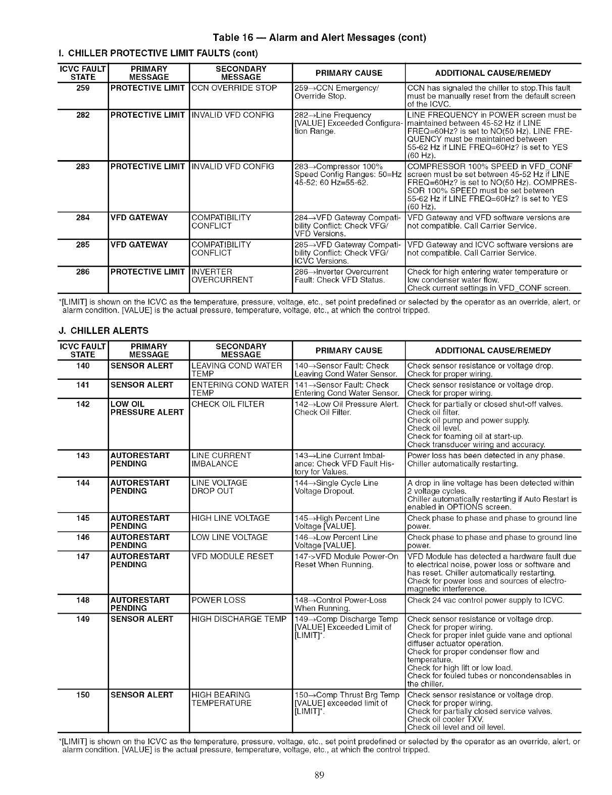
Table 16 -- Alarm and Alert Messages (cont)
I. CHILLER PROTECTIVE LIMIT FAULTS (cont)
ICVC FAULT
STATE
259
282
283
284
285
286
PRIMARY
MESSAGE
PROTECTIVE LIMIT
PROTECTIVE LIMIT
PROTECTIVE LIMIT
VFD GATEWAY
VFD GATEWAY
PROTECTIVE LIMIT
SECONDARY
MESSAGE
CCN OVERRIDE STOP
INVALID VFD CONFIG
INVALID VFD CONFIG
COMPATIBILITY
CONFLICT
COMPATIBILITY
CONFLICT
INVERTER
OVERCURRENT
PRIMARY CAUSE
259_CCN Emergency/
Override Stop.
282-+Line Frequency
[VALUE] Exceeded Configura-
tion Range.
283_Compressor 100%
Speed Config Ranges: 50=Hz
45-52; 60 Hz=55-62.
284_VFD Gateway Compati-
bility Conflict: Check VFG/
VFD Versions.
285-_VFD Gateway Compati-
bility Conflict: Check VFG/
ICVC Versions.
286_lnverter Overcurrent
Fault: Check VFD Status.
ADDITIONAL CAUSE/REMEDY
CCN has signaled the chiller to stop.This fault
must be manually reset from the default screen
of the ICVC.
LINE FREQUENCY in POWER screen must be
maintained between 45-52 Hz if LINE
FREQ=60Hz? is set to NO(50 Hz). LINE FRE-
QUENCY must be maintained between
55-62 Hz if LINE FREQ=60Hz? is set to YES
(60 Hz).
COMPRESSOR 100% SPEED in VFD CONF
screen must be set between 45-52 Hz [{ LINE
FREQ=60Hz? is set to NO(50 Hz). COMPRES-
SOR 100% SPEED must be set between
55-62 Hz if LINE FREQ=60Hz? is set to YES
(60 Hz).
VFD Gateway and VFD software versions are
not compatible. Call Carrier Service.
VFD Gateway and ICVC software versions are
not compatible. Call Carrier Service.
Check for high entering water temperature or
low condenser water flow.
Check current settings in VFD CONF screen.
*[LIMIT] is shown on the ICVC as the temperature, pressure, voltage, etc., set point predefined or selected by the operator as an override, alert, or
alarm condition. [VALUE] is the actual pressure, temperature, voltage, etc., at which the control tripped.
J. CHILLER ALERTS
ICVC FAULT
STATE
140
141
142
143
144
145
146
147
PRIMARY
MESSAGE
SENSOR ALERT
SENSOR ALERT
LOW OIL
PRESSURE ALERT
AUTORESTART
PENDING
AUTORESTART
PENDING
AUTORESTART
PENDING
AUTORESTART
PENDING
AUTORESTART
PENDING
SECONDARY
MESSAGE
LEAVING COND WATER
TEMP
ENTERING COND WATER
TEMP
CHECKOILFI_ER
LINECURRENT
IMBALANCE
LINEVOLTAGE
DROPOUT
HIGH LINE VOLTAGE
LOW LINE VOLTAGE
VFD MODULE RESET
148 AUTORESTART POWER LOSS
PENDING
149 SENSOR ALERT HIGH DISCHARGE TEMP
150 SENSOR ALERT HIGH BEARING
TEMPERATURE
PRIMARY CAUSE
140-_Sensor Fault: Check
Leaving Cond Water Sensor.
141_Sensor Fault: Check
Entering Cond Water Sensor.
142_Low Oil Pressure Alert.
Check Oil Filter.
143-_Line Current Imbal-
ance: Check VFD Fault His-
tory for Values.
144-+Single Cycle Line
Voltage Dropout.
145_High Percent Line
Voltage [VALUE].
146_Low Percent Line
Voltage [VALUE].
147->VFD Module Power-On
Reset When Running.
148_Control Power-Loss
When Running.
149_Comp Discharge Temp
[VALUE] Exceeded Limit of
[LIMIT]*.
150_Comp Thrust Brg Temp
[VALUE] exceeded limit of
[LIMIT]*.
ADDITIONAL CAUSE/REMEDY
Check sensor resistance or voltage drop.
Check for proper wiring.
Check sensor resistance or voltage drop.
Check for proper wiring.
Check for partially or closed shut-off valves.
Check oil filter.
Check oil pump and power supply.
Check oil level.
Check for foaming oil at start-up.
Check transducer wiring and accuracy.
Power loss has been detected in any phase.
Chiller automatically restarting.
A drop in line voltage has been detected within
2 voltage cycles.
Chiller automatically restarting ifAuto Restart is
enabled in OPTIONS screen.
Check phase to phase and phase to ground line
)ower.
Check phase to phase and phase to ground line
)ower.
VFD Module has detected a hardware fault due
to electrical noise, power loss or software and
has reset. Chiller automatically restarting.
Check for power loss and sources of electro-
magnetic interference.
Check 24 vac control power supply to ICVC.
Check sensor resistance or voltage drop.
Check for proper wiring.
Check for proper inlet guide vane and optional
diffuser actuator operation.
Check for proper condenser flow and
temperature.
Check for high lift or low load.
Check for fouled tubes or noncondensables in
the chiller.
Check sensor resistance or voltage drop.
Check for proper wiring.
Check for partially closed service valves.
Check oil cooler TXV.
Check oil level and oil level.
*[LIMIT] is shown on the ICVC as the temperature, pressure, voltage, etc., set point predefined or selected by the operator as an override, alert, or
alarm condition. [VALUE] is the actual pressure, temperature, voltage, etc., at which the control tripped.
89
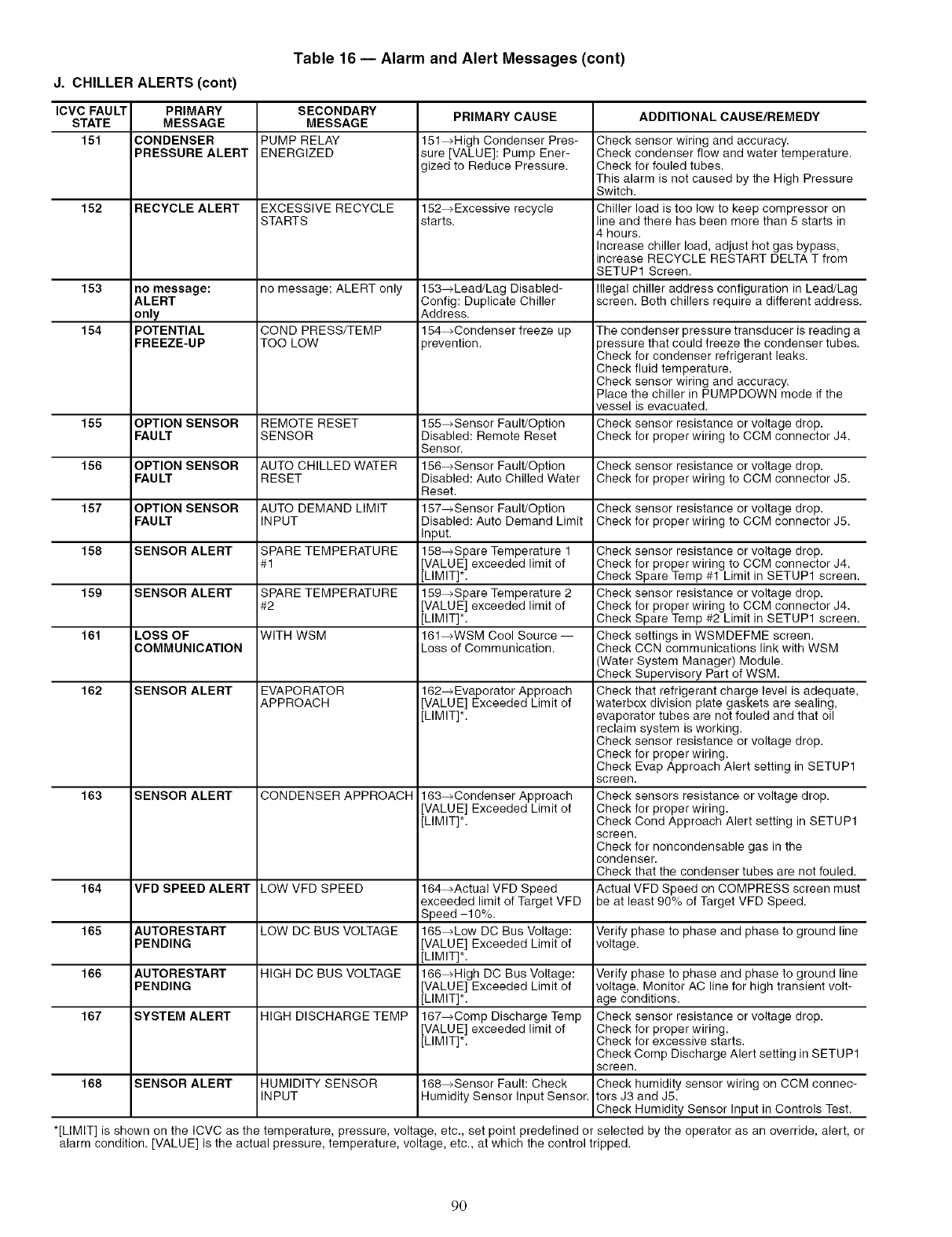
Table 16 -- Alarm and Alert Messages (cont)
J. CHILLER ALERTS (cont)
ICVC FAULT PRIMARY SECONDARY PRIMARY CAUSE ADDITIONAL CAUSE/REMEDY
STATE MESSAGE MESSAGE
151 CONDENSER PUMP RELAY 151_High Condenser Pres- Check sensor wiring and accuracy.
PRESSURE ALERT ENERGIZED sure [VALUE]: Pump Ener- Check condenser flow and water temperature.
gized to Reduce Pressure. Check for fouled tubes.
This alarm is not caused by the High Pressure
Switch.
152 RECYCLE ALERT EXCESSIVE RECYCLE 152_Excessive recycle Chiller load is too low to keep compressor on
STARTS starts, line and there has been more than 5 starts in
4 hours.
Increase chiller load, adjust hot gas bypass,
increase RECYCLE RESTART DELTA T from
SETUP1 Screen.
153 no message: no message; ALERT only 153_Lead/Lag Disabled- Illegal chiller address configuration in Lead/Lag
ALERT Config: Duplicate Chiller screen. Both chillers require a different address.
only Address.
154 POTENTIAL COND PRESS/TEMP 154_Condenser freeze up The condenser pressure transducer is reading a
FREEZE=UP TOO LOW )revention. 3ressure that could freeze the condenser tubes.
Check for condenser refrigerant leaks.
Check fluid temperature.
Check sensor wiring and accuracy.
Place the chiller in PUMPDOWN mode if the
vessel is evacuated.
155 OPTION SENSOR REMOTE RESET 155-_Sensor Fault/Option Check sensor resistance or voltage drop.
FAULT SENSOR Disabled: Remote Reset Check for proper wiring to CCM connector J4.
Sensor.
156 OPTION SENSOR AUTO CHILLED WATER 156_-_Sensor Fault/Option Check sensor resistance or voltage drop.
FAULT RESET Disabled: Auto Chilled Water Check for proper wiring to CCM connector J5.
Reset.
157 OPTION SENSOR AUTO DEMAND LIMIT 157-_Sensor Fault/Option Check sensor resistance or voltage drop.
FAULT INPUT Disabled: Auto Demand Limit Check for proper wiring to CCM connector J5.
Input.
158 SENSOR ALERT SPARE TEMPERATURE 158_-_Spare Temperature 1
#1 [VALUE] exceeded limit of
[LIMIT]*.
159 SENSOR ALERT SPARE TEMPERATURE 159_Spare Temperature 2
#2 [VALUE] exceeded limit of
[LIMIT]*.
161 LOSS OF WITH WSM 161_-_WSM Cool Source --
COMMUNICATION Loss of Communication.
162 SENSOR ALERT EVAPORATOR
APPROACH 162-_ Evaporator Approach
[VALUE] Exceeded Limit of
[LIMIT]*.
Check sensor resistance or voltage drop.
Check for proper wiring to CCM connector J4.
Check Spare Temp #1 Limit in SETUP1 screen.
Check sensor resistance or voltage drop.
Check for proper wiring to CCM connector J4.
Check Spare Temp #2 Limit in SETUP1 screen.
Check settings in WSMDEFME screen.
Check CCN communications link with WSM
(Water System Manager) Module.
Check Supervisory Part of WSM.
Check that refrigerant charge level is adequate,
waterbox division plate gaskets are sealing,
evaporator tubes are not fouled and that oil
reclaim system is working.
Check sensor resistance or voltage drop.
Check for proper wiring.
Check Evap Approach Alert setting in SETUP1
screen.
Check sensors resistance or voltage drop.
Check for proper wiring.
Check Cond Approach Alert setting in SETUP1
screen.
Check for noncondensable gas in the
condenser.
Check that the condenser tubes are not fouled.
Actual VFD Speed on COMPRESS screen must
be at least 90% of Target VFD Speed.
163 SENSOR ALERT CONDENSER APPROACH 163-_Condenser Approach
[VALUE] Exceeded Limit of
[LIMIT]*.
164 VFD SPEED ALERT LOW VFD SPEED 164_Actual VFD Speed
exceeded limit of Target VFD
Speed -10%.
165 AUTORESTART LOW DC BUS VOLTAGE 165_Low DC Bus Voltage: Verify phase to phase and phase to ground line
PENDING [VALUE] Exceeded Limit of voltage.
[LIMIT]*.
166 AUTORESTART HIGH DC BUS VOLTAGE 166_High DC Bus Voltage: Verify phase to phase and phase to ground line
PENDING [VALUE] Exceeded Limit of voltage. Monitor AC line for high transient volt-
[LIMIT]*. age conditions.
167 SYSTEM ALERT HIGH DISCHARGE TEMP 167_Comp Discharge Temp Check sensor resistance or voltage drop.
[VALUE] exceeded limit of Check for proper wiring.
[LIMIT]*. Check for excessive starts.
Check Comp Discharge Alert setting in SETUP1
screen.
168 SENSOR ALERT HUMIDITY SENSOR 168-_Sensor Fault: Check Check humidity sensor wiring on CCM connec-
INPUT Humidity Sensor Input Sensor. tots J3 and J5.
Check Humidity Sensor Input in Controls Test.
*[LIMIT] is shown on the ICVC as the temperature, pressure, volta e, etc., set point predefined or selected by the operator as an override, alert, or
alarm condition. [VALUE] is the actual pressure, temperature, voltage, etc., at which the control tripped.
90
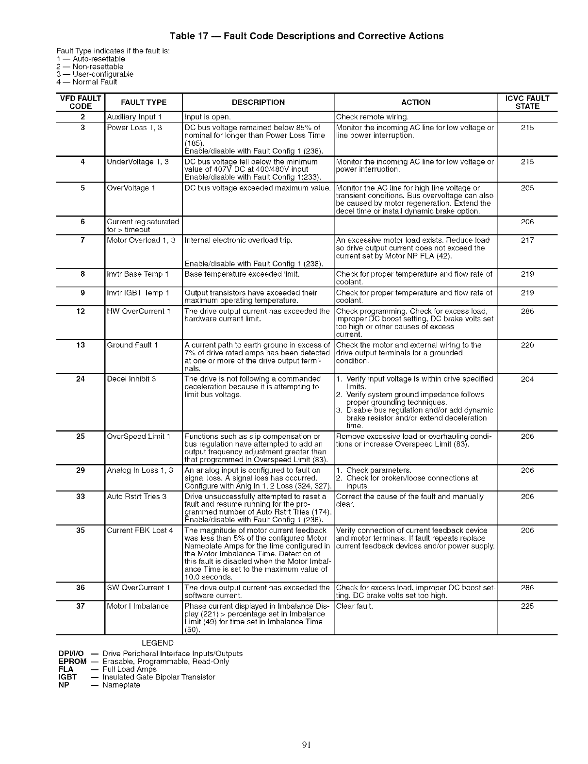
Table 17 -- Fault Code Descriptions and Corrective Actions
Fault Type indicates if the fault is:
1 -- Auto-resettable
2 -- Nomresettable
3- User-configurable
4 -- Normal Fault
VFD FAULT FAULT TYPE DESCRIPTION ACTION ICVC FAULT
CODE STATE
2 Auxiliary Input 1 Input is open. Check remote wiring.
3Power Loss 1, 3 DC bus voltage remained below 85% of Monitor the incoming AC line for low voltage or 215
nominal for longer than Power Loss Time line power interruption.
(185).
Enable/disable with Fault Config 1 (238).
4 UnderVoltage 1,3 DC bus voltage fell below the minimum Monitor the incoming AC line for low voltage or 215
value of 407V DC at 400/480V input )ower interruption.
Enable/disable with Fault Config 1(233).
5 OverVoltage 1 DC bus voltage exceeded maximum value. Monitor the AC line for high line voltage or 205
transient conditions. Bus overvoltage can also
be caused by motor regeneration. Extend the
decel time or install dynamic brake option.
6 Current reg saturated 206
for > timeout
7 Motor Overload 1, 3 Internal electronic overload trip. An excessive motor load exists. Reduce load 217
so drive output current does not exceed the
current set by Motor NP FLA (42).
Enable/disable with Fault Config 1 (238).
8 Invtr Base Temp 1 Base temperature exceeded limit. Check for proper temperature and flow rate of 219
coolant.
9 Invtr IGBT Temp 1 Output transistors have exceeded their Check for proper temperature and flow rate of 219
maximum operating temperature, coolant.
12 HW OverCurrent 1 The drive output current has exceeded the Check programming. Check for excess load, 286
hardware current limit, improper DC boost setting, DC brake volts set
too high or other causes of excess
cu rrent.
13 Ground Fault 1 A current path to earth ground in excess of Check the motor and external wiring to the 220
7% of drive rated amps has been detected drive output terminals for a grounded
at one or more of the drive output termF condition.
nals.
24 Decel Inhibit 3 The drive is not following a commanded 1. Verify input voltage is within drive specified 204
deceleration because it is attempting to limits.
limit bus voltage. 2. Verify system ground impedance follows
proper grounding techniques.
3. Disable bus regulation and/or add dynamic
brake resistor and/or extend deceleration
time.
25 OverSpeed Limit 1 Functions such as slip compensation or Remove excessive load or overhauling condF 206
bus regulation have attempted to add an tions or increase Overspeed Limit (83).
output frequency adjustment greater than
that programmed in Overspeed Limit (83).
29 Analog In Loss 1,3 An analog input is configured to fault on 1. Check parameters. 206
signal loss. A signal loss has occurred. 2. Check for broken/loose connections at
Configure with Anlg In 1,2 Loss (324, 327). inputs.
33 Auto Rstrt Tries 3 Drive unsuccessfully attempted to reset a Correct the cause of the fault and manually 206
fault and resume running for the pro- clear.
grammed number of Auto Rstrt Tries (174).
Enable/disable with Fault Config 1 (238).
35 Current FBK Lost 4 The magnitude of motor current feedback Verify connection of current feedback device 206
was less than 5% of the configured Motor and motor terminals. If fault repeats replace
Nameplate Amps for the time configured in current feedback devices and/or power supply.
the Motor Imbalance Time. Detection of
this fault is disabled when the Motor Imbal-
ance Time is set to the maximum value of
10.0 seconds.
36 SW OverCurrent 1 The drive output current has exceeded the Check for excess load, improper DC boost set- 286
software current, ting. DC brake volts set too high.
37 Motor I Imbalance Phase current displayed in Imbalance Dis- Clear fault. 225
play (221) > percentage set in Imbalance
Limit (49) for time set in Imbalance Time
(50).
LEGEND
DPI/I/O -- Drive Peripheral Interface Inputs/Outputs
EPROM -- Erasable, Programmable, Read-Only
FLA -- Full Load Amps
IGBT -- Insulated Gate Bipolar Transistor
NP -- Nameplate
91
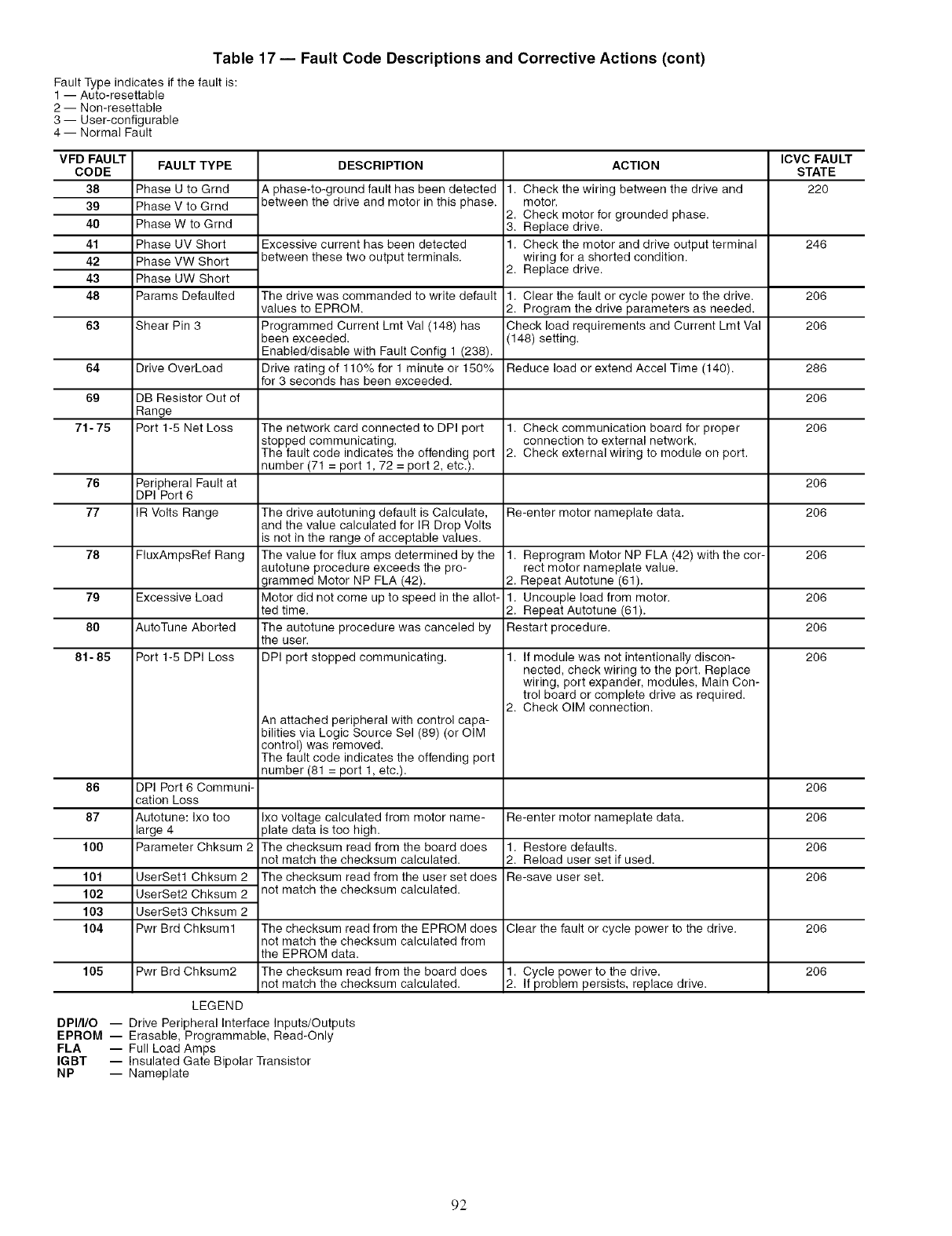
Table 17 -- Fault Code Descriptions and Corrective Actions (cont)
Fault Type indicates if the fault is:
1 -- Auto-resettable
2 -- Nomresettable
3 -- User-configurable
4 -- Normal Fault
VFD FAULT
CODE
38
39
40
41
42
43
48
63
64
6g
71- 75
76
77
78
7g
80
81- 85
86
87
100
101
102
103
104
105
FAULT TYPE
Phase U to Grnd
Phase V to Grnd
Phase W to Grnd
Phase UV Short
Phase VW Short
Phase UW Short
Params Defaulted
Shear Pin 3
Drive OverLoad
DB Resistor Out of
Range
Port 1-5 Net Loss
Peripheral Fault at
DPI Port 6
IR Volts Range
FluxAmpsRef Rang
Excessive Load
AutoTune Aborted
Port 1-6 DPI Loss
DPI Port 6 Communi-
cation Loss
Autotune: Ixo too
large 4
Parameter Chksum 2
UserSetl Chksum 2
UserSet2 Chksum 2
UserSet3 Chksum 2
Pwr Brd Chksuml
DESCRIPTION
A phase-to-ground fault has been detected
between the drive and motor in this phase.
Excessive current has been detected
between these two output terminals•
The drive was commanded to write default
values to EPROM.
Programmed Current Lint Val (148) has
been exceeded.
Enabled/disable with Fault Config 1 (238)•
Drive rating of 110% for 1 minute or 150%
for 3 seconds has been exceeded•
The network card connected to DPI port
stopped communicating.
The fault code indicates the offending port
number (71 = port 1, 72 = port 2, etc.).
The drive autotuning default is Calculate,
and the value calculated for IR Drop Volts
is not in the range of acceptable values.
The value for flux amps determined by the
autotune procedure exceeds the pro-
grammed Motor NP FLA (42).
Motor did not come up to speed in the allot-
ted time.
The autotune procedure was canceled by
the user.
DPI port stopped communicating•
An attached peripheral with control capa-
bilities via Logic Source Sel (89) (or OIM
control) was removed.
The fault code indicates the offending port
number (81 = port 1, etc.).
Ixo voltage calculated from motor name-
)late data is too high.
The checksum read from the board does
not match the checksum calculated•
The checksum read from the user set does
not match the checksum calculated•
ACTION
• Check the wiring between the drive and
motor.
2. Check motor for grounded phase.
3. Replace drive•
• Check the motor and drive output terminal
wiring for a shorted condition•
2. Replace drive•
• Clear the fault or cycle power to the drive•
2. Program the drive parameters as needed.
Check load requirements and Current Lmt Val
(148) setting.
Reduce load or extend Accel Time (140)•
• Check communication board for proper
connection to external network.
2. Check external wiring to module on port.
Re-enter motor nameplate data.
• Reprogram Motor NP FLA (42) with the cor-
rect motor nameplate value.
2. Repeat Autotune (61).
• Uncouple load from motor.
2. Repeat Autotune (61).
Restart procedure.
• If module was not intentionally discon-
nected, check wiring to the port. Replace
wiring, port expander, modules, Main Con-
trol board or complete drive as required•
2. Check OIM connection•
Re-enter motor nameplate data.
• Restore defaults.
2. Reload user set if used.
Re-save user set.
Clear the fault or cycle power to the drive•
Pwr Brd Chksum2
The checksum read from the EPROM does
not match the checksum calculated from
the EPROM data.
The checksum read from the board does
not match the checksum calculated• • Cycle power to the drive•
2. If problem persists, replace drive•
ICVC FAULT
STATE
22O
246
206
206
286
206
206
206
206
206
206
206
206
206
206
206
206
206
206
LEGEND
DPI/I/O -- Drive Peripheral Interface Inputs/Outputs
EPROM -- Erasable, Programmable, Read-Only
FLA -- Full Load Amps
IGBT -- Insulated Gate Bipolar Transistor
NP -- Nameplate
92
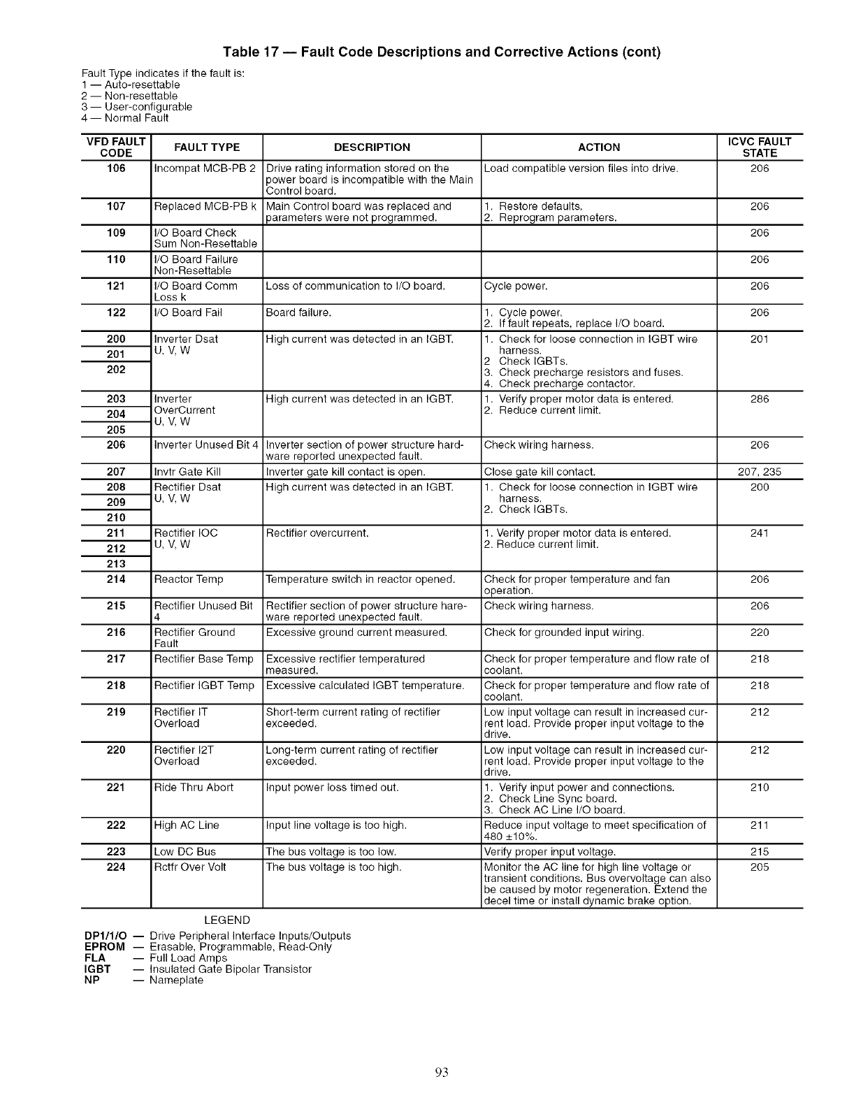
Table 17 -- Fault Code Descriptions and Corrective Actions (cont)
Fault Type indicates if the fault is:
1 -- Auto-resettable
2 -- Non-resettable
3- User-configurable
4 -- Normal Fault
VFD FAULT FAULT TYPE DESCRIPTION ACTION ICVC FAULT
CODE STATE
106 Incompat MCB-PB 2 Drive rating information stored on the Load compatible version files into drive. 206
3ower board is incompatible with the Main
Control board.
Replaced MCB-PB k Main Control board was replaced and 1. Restore defaults, 206
3arameters were not programmed, 2. Reprogram parameters.
I/O Board Check 206
Sum Non-Resettable
I/O Board Failure 206
Non-Resettable
I/O Board Comm Loss of communication to I/O board, Cycle power. 206
Loss k
I/O Board Fail Board failure. 206
High current was detected in an IGBT. 201
107
109
110
121
122
2O0
201
202
203
204
205
206
207
208
209
210
211
212
213
214
Inverter Dsat
u,v,w
Inverter
OverCurrent
u,v,w
Invtr Gate Kill
Rectifier Dsat
u,v,w
High current was detected in an IGBT.
1. Cycle power,
2. If fault repeats, replace I/O board,
1. Check for loose connection in IGBT wire
harness,
2 Check IGBTs.
3. Check precharge resistors and fuses.
4. Check precharge contactor.
1, Verify proper motor data is entered.
2. Reduce current limit. 286
Inverter Unused Bit 4 Inverter section of power structure hard- Check wiring harness. 206
ware reported unexpected fault.
Inverter gate kill contact is open. 207, 235
High current was detected in an IGBT. 200
Rectifier IOC
u,v,w
Close gate kill contact.
1. Check for loose connection in IGBT wire
harness,
2, Check IGBTs.
1, Verify proper motor data is entered.
2, Reduce current limit.
Rectifier overcurrent. 241
Reactor Temp Temperature switch in reactor opened, Check for proper temperature and fan 206
operation.
215 Rectifier Unused Bit Rectifier section of power structure hare- Check wiring harness. 206
4 ware reported unexpected fault.
216 Rectifier Ground Excessive ground current measured. Check for grounded input wiring. 220
Fault
217 Rectifier Base Temp Excessive rectifier temperatured Check for proper temperature and flow rate of 218
measured, coolant.
218 Rectifier IGBT Temp Excessive calculated IGBT temperature. Check for proper temperature and flow rate of 218
coolant.
219 Rectifier IT Short-term current rating of rectifier Low input voltage can result in increased cur- 212
Overload exceeded, rent load. Provide proper input voltage to the
drive.
220 Rectifier 12T Long-term current rating of rectifier Low input voltage can result in increased cur- 212
Overload exceeded, rent load. Provide proper input voltage to the
drive.
221 Ride Thru Abort Input power loss timed out. 1. Verify input power and connections. 210
2, Check Line Sync board.
3. Check AC Line I/O board.
222 High AC Line Input line voltage is too high. Reduce input voltage to meet specification of 211
480 _+10%.
223 Low DC Bus The bus voltage is too low. Verify proper input voltage. 215
224 Rctfr Over Volt The bus voltage is too high. Monitor the AC line for high line voltage or 205
transient conditions, Bus overvoltage can also
be caused by motor regeneration. Extend the
decel time or install dynamic brake option.
LEGEND
DP1/1/O -- Drive Peripheral Interface Inputs/Outputs
EPROM -- Erasable, Programmable, Read-Only
FLA -- Full Load Amps
IGBT -- Insulated Gate Bipolar Transistor
NP -- Nameplate
93
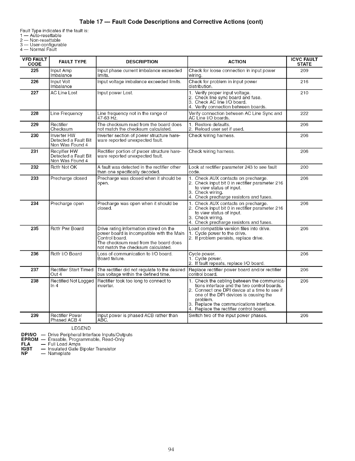
Table 17 -- Fault Code Descriptions and Corrective Actions (cont)
Fault Type indicates if the fault is:
1 -- Auto-resettable
2 -- Non-resettable
3 -- User-configurable
4 -- Normal Fault
VFD FAULT FAULT TYPE DESCRIPTION ACTION ICVC FAULT
CODE STATE
225 Input Amp Input phase current imbalance exceeded Check for loose connection in input power 209
Imbalance limits, wiring.
226 Input Volt Input voltage imbalance exceeded limits. Check for problem in input power 216
Imbalance distribution.
227 AC Line Lost Input power Lost. .Verify proper input voltage. 210
2. Check line sync board and fuse.
3. Check AC line I/O board.
4. Verify connection between boards.
228 Line Frequency Line frequency not in the range of Verify connection between AC Line Sync and 222
47-63 Hz. AC Line I/O boards.
229 Rectifier The checksum read from the board does .Restore defaults. 206
Checksum not match the checksum calculated. 2. Reload user set if used.
230 Inverter HW Inverter section of power structure hare- Check wiring harness. 206
Detected a Fault Bit ware reported unexpected fault.
Non Was Found 4
231 Recyifier HW Rectifier portion of pwoer structure hare- Check wiring harness. 206
Detected a Fault Bit ware reported unexpected fault.
Non Was Found 4
232 Rctfr Not OK A fault was detected in the rectifier other Look at rectifier parameter 243 to see fault 200
than one specifically decoded, code.
233 Precharge closed Precharge was closed when it should be .Check AUX contacts on precharge. 206
open. 2. Check input bit 0 in rectifier parameter 216
to view status of input.
3. Check wiring.
4. Check precharge resistors and fuses.
234 Precharge open Precharge was open when it should be .Check AUX contacts on precharge. 206
closed. 2. Check input bit 0 in rectifier parameter 216
to view status of input.
3. Check wiring.
4. Check precharge resistors and fuses.
235 Rctfr Pwr Board Drive rating information stored on the Load compatible version files into drive. 206
)ower board is incompatible with the Main .Cycle power to the drive.
Control board. 2. If problem persists, replace drive.
The checksum read from the board does
not match the checksum calculated.
236 Rctfr I/O Board Loss of communication to I/O board. Cycle power. 206
Board failure. .Cycle power.
2. If fault repeats, replace I/O board.
237 Rectifier Start Timed The rectifier did not regulate to the desired Replace rectifier power board and/or rectifier 206
Out 4 bus voltage within the defined time. control board.
238 Rectified Not Logged Rectifier took too long to connect to .Check the cabling between the communica- 206
In 4 inverter, tions interface and the two control boards.
2. Connect one DPI device at a time to see if
one of the DPI devices is causing the
problem.
3. Replace the communications interface.
4. Replace the rectifier control board.
239 Rectifier Power Input power is phased ACB rather than Switch two of the input power phases. 206
Phased ACB 4 ABC.
LEGEND
DPI/I/O -- Drive Peripheral Interface Inputs/Outputs
EPROM -- Erasable, Programmable, Read-Only
FLA -- Full Load Amps
IGBT -- Insulated Gate Bipolar Transistor
NP -- Nameplate
94
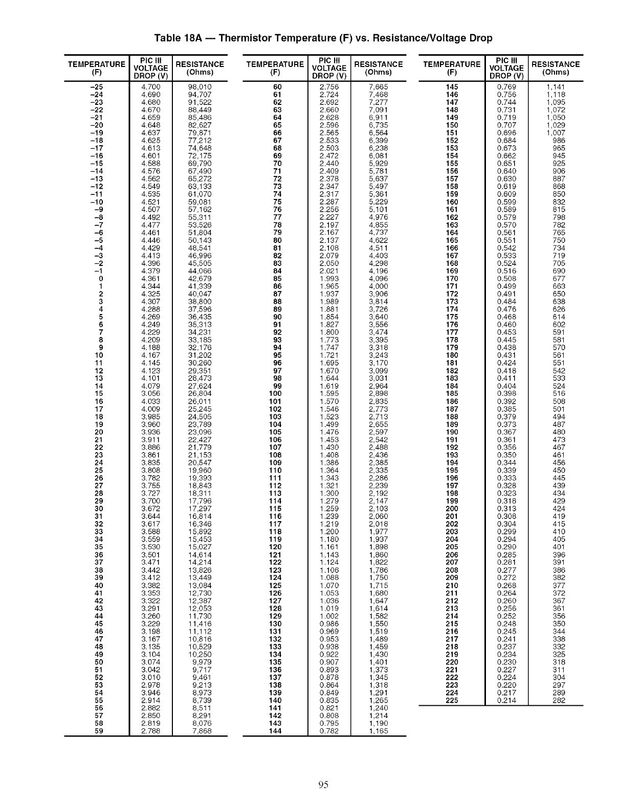
TEMPERATURE
-25
-24
-23
-22
-21
-20
-19
-18
-17
-16
-15
-14
-13
-12
-11
-10
-9
-8
-7
-6
-5
-4
-3
-2
-1
0
1
2
3
4
5
6
7
8
9
10
11
12
13
14
15
16
17
18
19
20
21
22
23
24
25
26
27
28
29
30
31
32
33
34
35
36
37
38
39
40
41
42
43
44
45
46
47
48
49
50
51
52
53
54
55
58
57
58
59
Table 18A -- Thermistor Temperature (F) vs. Resistance/Voltage Drop
PIC III
VOLTAGE
DROP (V)
4.700
4.690
4.680
4.670
4.659
4.648
4.637
4.625
4.613
4.601
4.588
4.576
4.562
4.549
4.535
4.521
4.507
4.492
4.477
4.461
4.446
4.429
4.413
4.396
4.379
4.361
4.344
4.325
4.307
4.288
4.269
4.249
4.229
4.209
4.188
4.167
4.145
4.123
4.101
4.079
3.056
4.033
4.009
3.985
3.960
3.936
3.911
3.886
3.861
3.835
3,808
3.782
3.755
3.727
3.700
3.672
3.644
3.617
3.588
3.559
3.530
3.501
3.471
3.442
3.412
3.382
3.353
3.322
3.291
3.260
3.229
3.198
3.167
3.135
3.104
3.074
3.042
3.010
2.978
3.946
2.914
2.882
2.850
2.819
2.788
RESISTANCE RESISTANCE
(Ohms) (Ohms)
TEMPERATURE
(F)
98,010 60
94,707 61
91,522 62
88,449 63
85,486 64
82,627 65
79,871 66
77,212 67
74,648 68
72,175 69
69,790 70
67,490 71
65,272 72
63,133 73
61,070 74
59,081 75
57,162 76
55,311 77
53,526 78
51,804 79
50,143 80
48,541 81
46,996 82
45,505 83
44,066 84
42,679 85
41,339 86
40,047 87
38,800 88
37,596 89
36,435 90
35,313 91
34,231 92
33,185 93
32,176 94
31,202 95
30,260 96
29,351 97
28,473 98
27,624 99
26,804 100
26,011 101
25,245 102
24,505 103
23,789 104
23,096 105
22,427 106
21,779 107
21,153 108
20,547 109
19,960 110
19,393 111
18,843 112
18,311 113
17,796 114
17,297 115
16,814 116
16,346 117
15,892 118
15,453 119
15,027 120
14,614 121
14,214 122
13,826 123
13,449 124
13,084 125
12,730 126
12,387 127
12,053 128
11,730 129
11,416 130
11,112 131
10,816 132
10,529 133
10,250 134
9,979 135
9,717 136
9,461 137
9,213 138
8,973 139
8,739 140
8,511 141
8,291 142
8,076 143
7,868 144
PIC III
VOLTAGE
DROP (V)
2.756
2.724
2.692
2.660
2.628
2.596
2.565
2.533
2.503
2.472
2.440
2.409
2.378
2.347
2.317
2.287
2.256
2.227
2.197
2.167
2.137
2.108
2.079
2.050
2.021
1.993
1.965
1.937
1.989
1.881
1.854
1.827
1.800
1.773
1.747
1.721
1.695
1.670
1.644
1.619
1.595
1.570
1.546
1.523
1.499
1.476
1.453
1.430
1.408
1.386
1.364
1.343
1.321
1.300
1.279
1.259
1.239
1.219
1.200
1.180
1.161
1.143
1.124
1.106
1.088
1.070
1.053
1.036
1.019
1.002
0.986
0.969
0.953
0.938
0.922
0.907
0.893
0.878
0.864
0.849
0.835
0.821
0.808
0,795
0.782
TEMPERATURE
(F)
7,665 145
7,468 146
7,277 147
7,091 148
6,911 149
6,735 150
6,564 151
6,399 152
6,238 153
6,081 154
5,929 155
5,781 156
5,637 157
5,497 158
5,361 159
5,229 160
5,101 161
4,976 162
4,855 163
4,737 164
4,622 165
4,511 166
4,403 167
4,298 168
4,196 169
4,096 170
4,000 171
3,906 172
3,814 173
3,726 174
3,640 175
3,556 176
3,474 177
3,395 178
3,318 179
3,243 180
3,170 181
3,099 182
3,031 183
2,964 184
2,898 185
2,835 186
2,773 187
2,713 188
2,655 189
2,597 190
2,542 191
2,488 192
2,436 193
2,385 194
2,335 195
2,286 196
2,239 197
2,192 198
2,147 199
2,103 200
2,060 201
2,018 202
1,977 203
1,937 204
1,898 205
1,860 206
1,822 207
1,786 208
1,750 209
1,715 210
1,680 211
1,647 212
1,614 213
1,582 214
1,550 215
1,519 216
1,489 217
1,459 218
1,430 219
1,401 220
1,373 221
1,345 222
1,318 223
1,291 224
1,265 225
1,240
1,214
1,190
1,165
PIC III
VOLTAGE
DROP (V)
0.769
0.756
0.744
0.731
0.719
0.707
0.696
0.684
0.673
0.662
0.651
0.640
0.630
0.619
0.609
0.599
0,589
0.579
0.570
0.561
0.551
0.542
0.533
0.524
0.516
0.508
0.499
0.491
0,484
0.476
0.468
0.460
0.453
0.445
0,438
0,431
0,424
0.418
0.411
0,404
0.398
0.392
0.385
0.379
0.373
0.367
0.361
0.356
0.350
0.344
0.339
0.333
0.328
0.323
0.318
0.313
0.308
0.304
0.299
0.294
0.290
0.285
0.281
0.277
0.272
0.268
0.264
0.260
0.256
0.252
0.248
0.245
0.241
0.237
0.234
0.230
0.227
0.224
0.220
0.217
0.214
RESISTANCE
(Ohms)
1,141
1,118
1,095
1,072
1,050
1,029
1,007
986
965
945
925
906
887
868
850
832
815
798
782
765
75O
734
719
7O5
690
677
663
650
638
626
614
602
591
581
570
561
551
542
533
524
516
5O8
501
494
487
48O
473
467
461
456
45O
445
439
434
429
424
419
415
410
4O5
401
396
391
386
382
377
372
367
361
356
35O
344
338
332
325
318
311
3O4
297
289
282
9.5
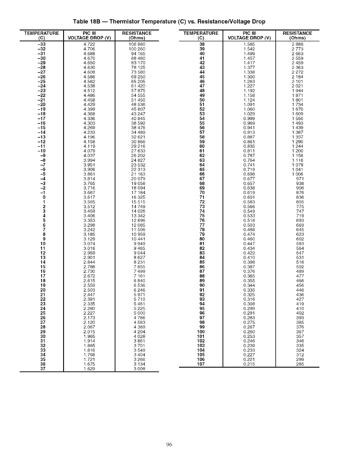
Table 18B -- Thermistor Temperature (C) vs. Resistance/Voltage Drop
TEMPERATURE
(c)
-33
-32
-31
-30
-29
-28
-27
-26
-25
-24
-23
-22
-21
-20
-19
-18
-17
-16
-15
-14
-13
-12
-11
-10
-9
--8
-7
-6
-6
-4
--3
-2
-1
0
1
2
3
4
5
6
7
8
9
10
11
12
13
14
15
16
17
18
19
2O
21
22
23
24
25
26
27
28
29
30
31
32
33
34
35
36
37
PIC III RESISTANCE
VOLTAGE DROP (V) (Ohms)
4.722 106 880
4.706
4.688
4.670
4.650
4.630
4.608
4.586
4.562
4.538
4.512
4.486
4.458
4.429
4.399
4.368
4.336
4.303
4.269
4.233
4.196
4.158
4.119
4.079
4.037
3.994
3.951
3.906
3.861
3.814
3.765
3.716
3.667
3.617
3.565
3.512
3.459
3.406
3.353
3.298
3.242
3.185
3.129
3.074
3.016
2.959
2.901
2.844
2.788
2.730
2.672
2.615
2.559
2.503
2.447
2.391
2.335
2.280
2.227
2.173
2.120
2.067
2.015
1.965
1.914
1.865
1.816
1.768
1.721
1.675
1.629
TEMPERATURE
(c)
38
100 260 39
94 165 40
88 480 41
83170 42
78125 43
73 580 44
69 250 45
65 205 46
61 420 47
57 875 48
54 555 49
51 450 50
48 536 51
45 807 52
43 247 53
40 845 54
38 592 55
38 476 56
34 489 57
32 621 58
30 866 59
29 216 60
27 633 61
26 202 62
24 827 63
23 532 64
22 313 65
21 163 66
20 079 67
19 058 68
18 094 69
17 184 70
16 325 71
15 515 72
14 749 73
14 026 74
13 342 75
12 696 76
12 085 77
11 506 78
10 959 79
10 441 80
9 949 81
9 485 82
9 044 83
8 627 84
8 231 85
7 855 86
7 499 87
7 161 88
6 840 89
6 536 90
6 246 91
5 971 92
5 710 93
5 461 94
5 225 95
5 000 96
4 786 97
4 583 98
4 389 99
4 204 100
4 028 101
3 861 102
3 701 103
3 549 104
3 404 105
3 266 106
3 134 107
3 008
PIC III
VOLTAGE DROP (V)
1.585
1.542
1.499
1.457
1.417
1.377
1.338
1.300
1.263
1.227
1.192
1.158
1.124
1.091
1.060
1.029
0.999
0.969
0.941
0.913
0.887
0.861
0.835
0.811
0.787
0.764
0.741
0.719
0.698
0.677
0.657
0.638
0.619
0.601
0.583
0.566
0.549
0.533
0.518
0.503
0.488
0.474
0.460
0.447
0.434
0.422
0.410
0.398
0.387
0.376
0.365
0.355
0.344
0.335
0.325
0.316
0.308
0.299
0.291
0.283
0.275
0.267
0.260
0.253
0.246
0.239
0.233
0.227
0.221
0.215
RESISTANCE
(Ohms)
2 888
2 773
2 663
2 559
2 459
2 363
2 272
2 184
2 101
2 021
1 944
1 871
1 801
1 734
1 670
1 609
1 550
1 493
1 439
1 387
1 337
1 290
1 244
1 200
1 158
1 116
1 079
1 041
1 006
971
938
906
876
836
8O5
775
747
719
693
669
645
623
6O2
583
564
547
531
516
5O2
489
477
466
456
446
436
427
419
410
4O2
393
385
376
367
357
346
335
324
312
299
285
96
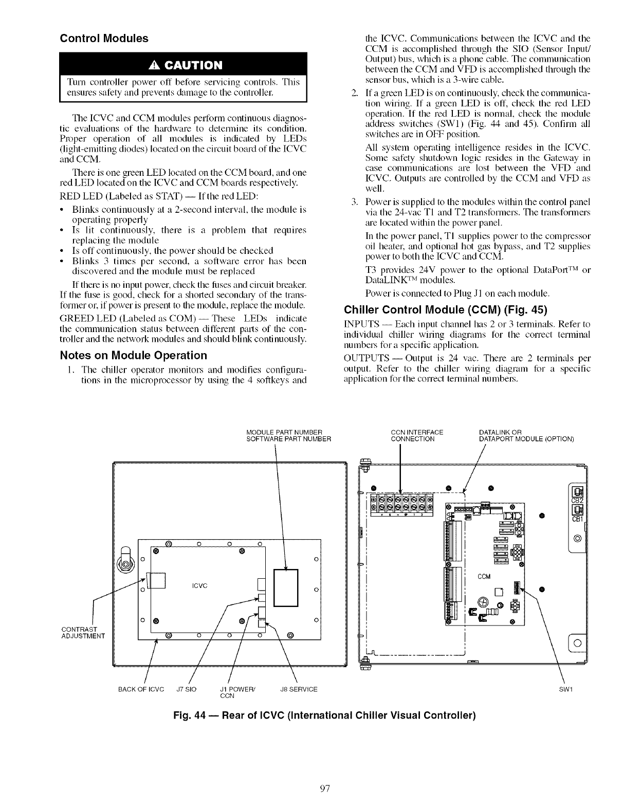
Control Modules
Turn controller power off before servicing controls. This
ensures safety and prevents &image to the controllec
The ICVC and CCM modules perform continuous diagnos-
tic evaluations of the hmdware to determine its condition.
Proper operation of all modules is indicated by LEDs
(light-emitting diodes) located on the circuit board of the ICVC
and CCM.
There is one green LED located on the CCM board, and one
red LED located on the ICVC and CCM boards respectively.
RED LED (Labeled as STAT) --If the red LED:
• Blinks continuously at a 2-second interval, the module is
operating properly
• Is lit continuously, there is a problem that requires
replacing the module
• Is off continuously, the power should be checked
• Blinks 3 times per second, a software error has been
discoveled and the module must be replaced
If there is no input powel, check the luses and circuit breaker
If the fuse is good, check for a shorted secondary of the trans-
former or. if power is present to the module, replace the module.
GREED LED (Labeled as COM)-- These LEDs indicate
the communication status between different paris of the con-
troller and the network modules and should blink continuously.
Notes on Module Operation
1. The chiller operator monitors and modifies configura-
tions in the microprocessor by using the 4 softkeys and
the ICVC. Communications between the [CVC and the
CCM is accomplished through the SIO (Sensor Input/
Output) bus, which is a phone cable. The communication
between the CCM and VFD is accomplished through the
sensor bus, which is a 3-wire cable.
2. If a green LED is on continuously, check the communica-
tion wiring. If a green LED is off. check the red LED
operation. If the red LED is normal, check the module
address switches (SWI) (Fig. 44 and 45). Confirm _dl
switches _ue in OFF position.
All system operating intelligence resides in the ICVC.
Some safety shutdown logic resides in the Gateway in
case communications are lost between the VFD and
ICVC. Outputs are controlled by the CCM and VFD as
well.
3. Power is supplied to the modules within the control panel
via the 24-vac TI and T2 transformers. The transformers
_u'elocated within the power panel.
In the power panel, TI supplies power to the compressor
oil heatel: and optional hot gas bypass, and T2 supplies
power to both the ICVC and CCM.
T3 provides 24V power to the optiomd DataPort TM or
DataLINK TM modules.
Power is connected to Plug Jl on each module.
Chiller Control Module (CCM) (Fig 45)
INPUTS -- Each input channel has 2 or 3 terminals. Refer to
individual chiller wiring diagrams for the con'ect terminal
numbers for a specific application.
OUTPUTS- Output is 24 vac. There are 2 termimds per
output. Refer to the chiller wiring diagram for a specific
application for the correct terminal numbel_.
CONTRAST
ADJUSTMENT
MODULE PART NUMBER
SOFTWARE PART NUMBER
@
BACK OFICVC
o o @ o \
ICVC [
/ / \
J7 SIO J1 POWER/ J8 SERVICE
CCN
CCN INTERFACE
CONNECTION /
We •/•
m
DATALINK OR
DATAPORT MODULE (OPTION)
[]
CB1
SWl
Fig 44 -- Rear of ICVC (International Chiller Visual Controller)
97
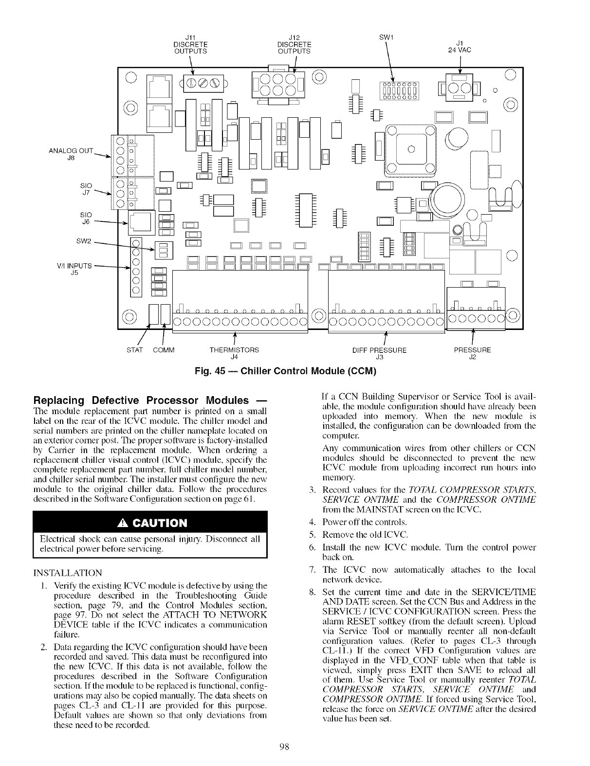
ANA' OUT
SIO
J6 "------.-
SW2
V/I INPUTS
J5
J1
24 VAC
o
° ©
Fig. 45 -- Chiller Control Module (CCM)
©
Replacing Defective Processor Modules i
The module replacement pan number is printed on a sm_dl
label on the rear of the ICVC module. The chiller model and
serial numbers tue printed on the chiller nameplate located on
an exterior corner post. The proper software is factory-installed
by Carrier in the replacement module. When ordering a
replacement chiller visual control (ICVC) module, specify the
complete replacement part number, lilll chiller model numbek
and chiller serial numbel: The installer must configure the new
module to the original chiller data. Follow the procedures
described in the Software Configuration section on page 61.
Electrical shock can cause pel,sonal injm 7. Disconnect all
electrical power before servicing.
INSTALLATION
1. Verify the existing ICVC module is defective by using the
procedure described in the Troubleshooting Guide
section, page 79, and the Control Modules section,
page 97. Do not select the ATTACH TO NETWORK
DEVICE table if the [CVC indicates a communication
failure.
2. Data regarding the ICVC configuration should have been
recorded and saved. This data must be reconfigured into
the new ICVC. If this data is not available, follow the
procedures described in the Software Configuration
section. If the module to be replaced is functional, config-
urations may also be copied manually. The &{ta sheets on
pages CL-3 and CL-II _u'e provided for this purpose.
Default values are shown so that only deviations from
these need to be recorded.
3.
4.
5.
6.
7.
8.
If a CCN Building Supervisor or Service Tool is avail-
able, the module configuration should have already been
uploaded into memory. When the new module is
installed, the configuration can be downloaded from the
computec
Any communication wires from other chillers or CCN
modules should be disconnected to prevent the new
ICVC module from uploading incorrect run hours into
memw 7.
Record wdues for the TOTAL COMPRESSOR STARTS,
SERVICE ONTIME and the COMPRESSOR ONTIME
from the MAINSTAT screen on the ICVC.
Power off the controls.
Remove the old ICVC.
Install the new ICVC module. Turn the control power
back on.
The [CVC now automatically attaches to the local
network device.
Set the current time and &tie in the SERVICE/TIME
AND DATE screen. Set the CCN Bus and Address in the
SERVICE /ICVC CONFIGURATION screen. Press the
alarm RESET softkey (from the default screen). Upload
via Service Tool or manually reenter all non-default
configuration values. (Refer to pages CL-3 through
CL-II.) If the correct VFD Configuration values are
displayed in the VFD_CONF table when that table is
viewed, simply press EXIT then SAVE to reload all
of them. Use Service Tool or manually reenter TOTAL
COMPRESSOR STARTS, SERVICE ONTIME and
COMPRESSOR ONTIME. [f forced using Service Tool,
release the force on SERVICE ONTIME after the desired
v_due has been set.
98
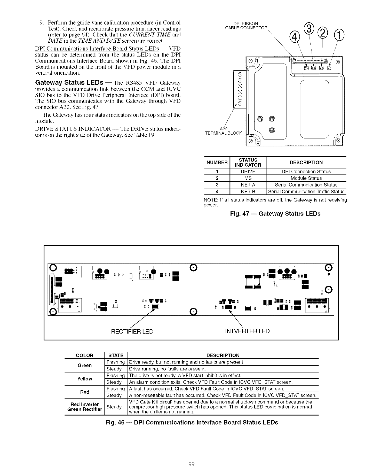
9. Performtheguidevanecalibrationprocedure(inControl
Test).Checkandrecalibratepressuretransducerleadings
(refertopage64).CheckthattheCURRENT TIME and
DATE in the TIMEAND DATE screen are correct.
DPI Communications Interface Board Status LEDs -- VFD
status can be determined from the status LEDs on the DPI
Communications Interface Board shown in Fig. 46. The DPI
Board is mounted on file fiont of the VFD power module in a
vertical orientation.
Gateway Status LEDs- The RS485 VFD Gateway
provides a communication link between the CCM and ICVC
SIO bus to the VFD Drive Peripheral Interface (DPI) board.
The SIO bus communicates with the Gateway through VFD
connector A32. See Fig. 47.
The Gateway has four status indicators on the top side of the
module.
DRIVE STATUS INDICATOR -- The DRIVE status indica-
tor is on the right side of the Gateway. See Table 19.
DPI RIBBON
CABLE CONNECTOR
A32
TERMINAL BLOCK
STATUS DESCRIPTION
NUMBER INDICATOR
1DRIVE DPI Connection Status
2 MS Module Status
3NET A Serial Communication Status
4 NET B Serial Communication Traffic Status
NOTE: If all status indicators are off, the Gateway is not receiving
power.
Fig. 47 -- Gateway Status LEDs
IJ uO
0 = T=0 Ill =
,7.11 ° °-°
N
RECTIFIER LED INTVERTER LED
COLOR
Gteen
Yellow
Red
Red Inverter
Green Rectifier
STATE
Flashing
Steady
Flashing
Steady
Flashing
Steady
Steady
DESCRIPTION
Drive ready, but not running and no faults are present
Drive running, no faults are present.
The drive is not ready. A VFD start inhibit is in effect.
An alarm condition exits. Check VFD Fault Code in ICVC VFD STAT screen.
A fault has occurred. Check VFD Fault Code in ICVC VFD STAT screen.
A non-resettable fault has occurred. Check VFD Fault Code in ICVC VFD STAT screen.
VFD Gate Kill circuit has opened due to a normal shutdown command or because the
compressor high pressure switch has opened. This status LED combination is normal
when the chiller is not running.
Fig. 46- DPI Communications Interface Board Status LEDs
99
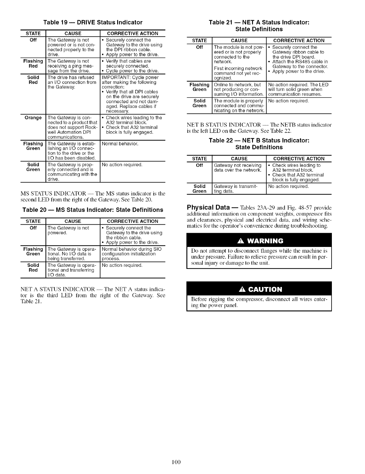
Table 19 -- DRIVE Status Indicator
STATE
Off
Flashing
Red
Solid
Red
Orange
Flashing
Green
CAUSE
The Gateway is not
powered or is not con-
nected properly to the
drive.
The Gateway is not
receiving a ping mes-
sage from the drive.
The drive has refused
an I/O connection from
the Gateway.
The Gateway is con-
nected to a product that
does not support Rock-
well Automation DPI
communications.
The Gateway is estab-
lishing an I/O connec-
tion to the drive or the
I/O has been disabled.
The Gateway is prop-
erly connected and is
communicating with the
drive.
CORRECTIVE ACTION
• Securely connect the
Gateway to the drive using
the DPI ribbon cable.
• Apply power to the drive.
• Verify that cables are
securely connected.
• Cycle power to the drive.
IMPORTANT: Cycle power
after making the following
correction:
• Verify that all DPI cables
on the drive are securely
connected and not dam-
aged. Replace cables if
necessary.
• Check wires leading to the
A32 terminal block.
• Check that A32 terminal
block is fully engaged.
Normal behavior.
Solid No action required.
Green
MS STATUS INDICATOR -- The MS status indicator is the
second LED from the fight of the Gateway. See Table 20.
Table 20 -- MS Status Indicator: State Definitions
STATE CAUSE
Off The Gateway is not
)owered.
Flashing
Green
Solid
Red
The Gateway is opera-
tional. No I/O data is
being transferred.
The Gateway is opera-
tional and transferring
I/O data.
CORRECTIVE ACTION
• Securely connect the
Gateway to the drive using
the ribbon cable.
• Apply power to the drive.
Normal behavior during SIC
configuration initialization
3rocess.
No action required.
NET A STATUS INDICATOR -- The NET A status indica-
tor is tile third LED from the right of the Gateway. See
Table 21.
Table 21 -- NET A Status Indicator:
State Definitions
STATE CAUSE CORRECTIVE ACTION
Off The module is not pow- • Securely connect the
ered or is not properly Gateway ribbon cable to
connected to the the drive DPI board.
network. • Attach the RS485 cable in
First incoming network Gateway to the connector.
command not yet rec- • Apply power to the drive.
ognized.
Flashing Online to network, but No action required. The LED
Green not producing or con- will turn solid green when
suming I/O information, communication resumes.
Solid The module is properly No action required.
Green connected and commu-
nicating on the network.
NET BSTATUS INDICATOR -- Tile NETB status indicator
is the left LED on file Gateway. See Table 22.
Table 22 -- NET B Status Indicator:
State Definitions
STATE CAUSE CORRECTIVE ACTION
Off Gateway not receiving • Check wires leading to
data over the network. A32 terminal block.
• Check that A32 terminal
block is fully engaged.
Solid Gateway is transmit- No action required.
Green ting data.
Physical Data -- Tables 23A-29 and Fig. 48-57 provide
additional information on component weights, compressor fits
and clearances, physical and electrical &Lta, and wiring sche-
matics for the operator's convenience during troubleshooting.
Do not attempt to disconnect flanges while the machine is
under pressure. Failure to relieve pressure can result in per-
somd injury or damage to the unit.
Before rigging the compressor, disconnect all wires enter-
ing the power panel.
100
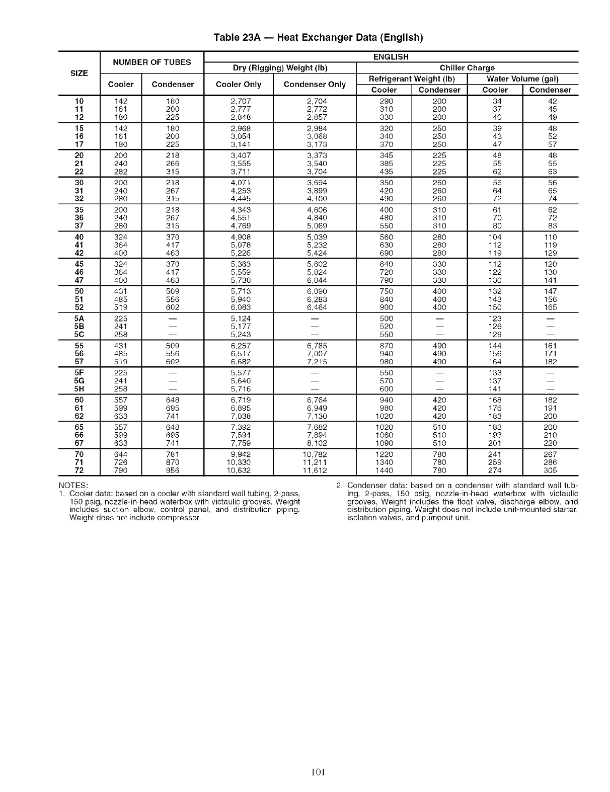
Table 23A -- Heat Exchanger Data (English)
SIZE
NUMBER OF TUBES Dry (Rigging) Weight (Ib)
Cooler Condenser Cooler Only Condenser Only Cooler Condenser Cooler
10 142 180 2,707 2,704 290 200 34 42
11 161 200 2,777 2,772 310 200 37 45
12 180 225 2,848 2,857 330 200 40 49
15 142 180 2,968 2,984 320 250 39 48
16 161 200 3,054 3,068 340 250 43 52
17 180 225 3,141 3,173 370 250 47 57
20 200 218 3,407 3,373 345 225 48 48
21 240 266 3,555 3,540 385 225 55 55
22 282 315 3,711 3,704 435 225 62 63
30 200 218 4,071 3,694 350 260 56 56
31 240 267 4,253 3,899 420 260 64 65
32 280 315 4,445 4,100 490 260 72 74
35 200 218 4,343 4,606 400 310 61 62
36 240 267 4,551 4,840 480 310 70 72
37 280 315 4,769 5,069 550 310 80 83
40 324 370 4,908 8,039 560 280 104 110
41 364 417 5,078 5,232 630 280 112 119
42 400 463 5,226 5,424 690 280 119 129
45 324 370 5,363 5,602 640 330 112 120
46 364 417 5,559 5,824 720 330 122 130
47 400 463 5,730 6,044 790 330 130 141
50 431 509 8,713 6,090 750 400 132 147
51 485 556 5,940 6,283 840 400 143 156
52 519 602 6,083 6,464 900 400 150 165
5A 225 -- 5,124 -- 500 -- 123 --
5B 241 -- 5,177 -- 520 -- 126 --
50 258 -- 5,243 -- 550 -- 129 --
55 431 509 6,257 6,785 870 490 144 161
56 485 556 6,517 7,007 940 490 156 171
57 519 602 6,682 7,215 980 490 164 182
5F 225 -- 5,577 -- 550 -- 133 --
5G 241 -- 5,640 -- 570 -- 137 --
5H 258 -- 5,716 -- 600 -- 141 --
60 557 648 6,719 6,764 940 420 168 182
61 599 695 6,895 6,949 980 420 176 191
62 633 741 7,038 7,130 1020 420 183 200
65 557 648 7,392 7,682 1020 510 183 200
66 599 695 7,594 7,894 1060 510 193 210
67 633 741 7,759 8,102 1090 510 201 220
70 644 781 9,942 10,782 1220 780 241 267
71 726 870 10,330 11,211 1340 780 259 286
72 790 956 10,632 11,612 1440 780 274 305
ENGLISH
Chiller Charge
Refrigerant Weight (Ib) Water Volume (gal)
Condenser
NOTES: 2. Condenser data: based on a condenser with standard wall tub-
1. Cooler data: based on a coolerwith standard wall tubing, 2-pass, ing, 2-pass, 150 psig, nozzle-in-head waterbox with victaulic
150 psig, nozzle-in-head waterbox with victaulic grooves. Weight grooves. Weight includes the float valve, discharge elbow, and
includes suction elbow, control panel, and distribution piping, distribution piping. Weight does not include unit-mounted starter,
Weight does not include compressor, isolation valves, and pumpout unit.
101
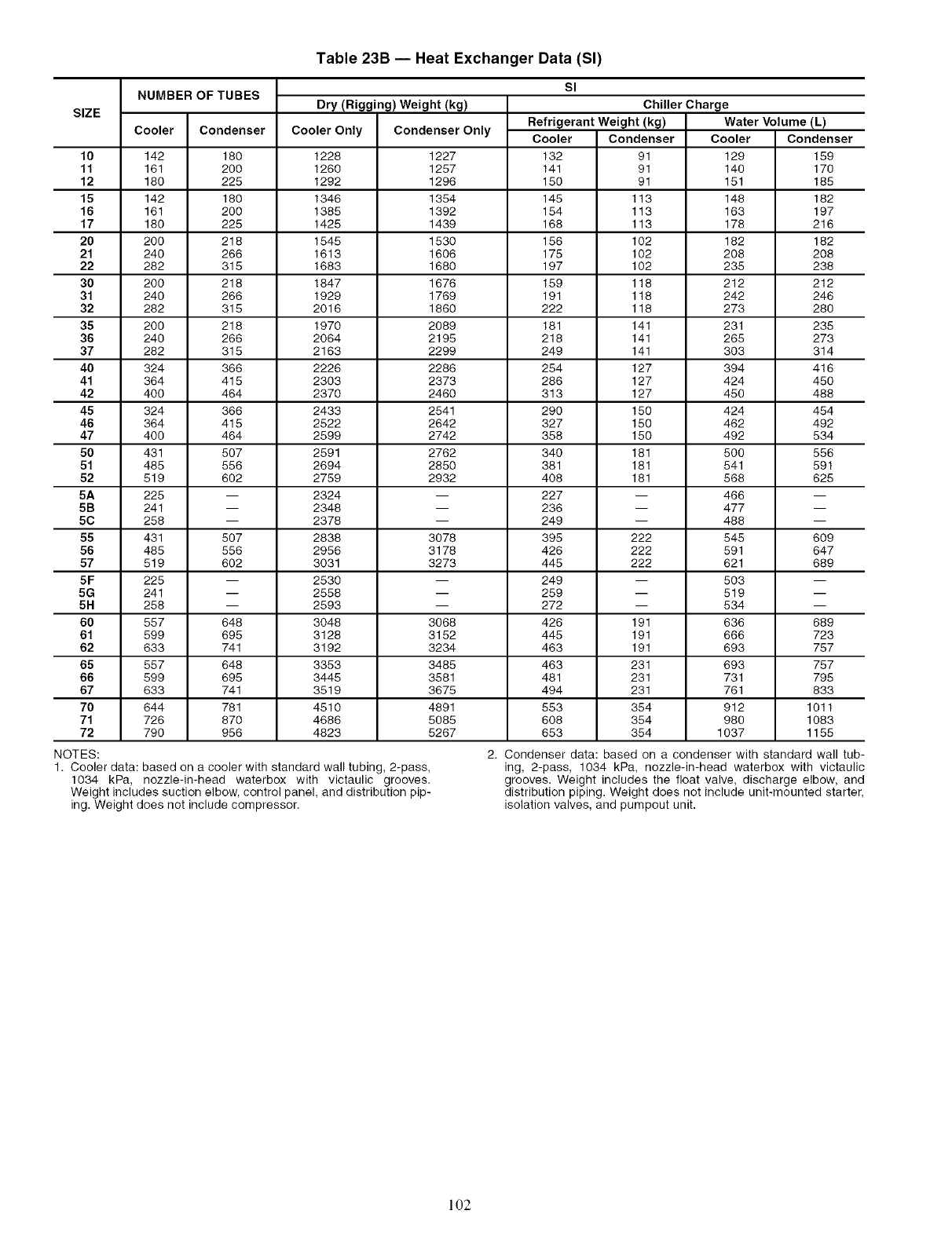
Table 23B -- Heat Exchanger Data (Sl)
SIZE
NUMBER OF TUBES Sl
Dry (Rigging) Weight (kg)
Cooler Condenser Cooler Only Condenser Only
10 142 180 1228 1227
11 161 200 1260 1257
12 180 225 1292 1296
15 142 180 1346 1354
16 161 200 1385 1392
17 180 225 1425 1439
20 200 218 1545 1530
21 240 266 1613 1606
22 282 315 1683 1680
30 200 218 1847 1676
31 240 266 1929 1769
32 282 315 2016 1860
35 200 218 1970 2089
36 240 266 2064 2195
37 282 315 2163 2299
40 324 366 2226 2286
41 364 415 2303 2373
42 400 464 2370 2460
45 324 366 2433 2541
46 364 415 2522 2642
47 400 464 2599 2742
50 431 507 2591 2762
51 485 556 2694 2850
52 519 602 2759 2932
5A 225 -- 2324 --
5B 241 -- 2348 --
50 258 -- 2378 --
55 431 507 2838 3078
56 485 556 2956 3178
57 519 602 3031 3273
5F 225 -- 2530 --
5G 241 -- 2558 --
5H 258 -- 2593 --
60 557 648 3048 3068
61 599 695 3128 3152
62 633 741 3192 3234
65 557 648 3353 3485
66 599 895 3445 3581
67 633 741 3519 3675
70 644 781 4510 4891
71 726 870 4686 5085
72 790 956 4823 5267
NOTES:
1. Cooler data: based on a cooler with standard wall tubing, 2-pass,
1034 kPa, nozzleqn-head waterbox with victaulic grooves.
Weight includes suction elbow, control panel, and distribution pip-
ing. Weight does not include compressor.
Refrigerant Weight(kg)
Cooler Condenser
132 91
141 91
150 91
145 113
154 113
168 113
156 102
175 102
197 102
159 118
191 118
222 118
181 141
218 141
249 141
254 127
286 127
313 127
290 150
327 150
358 150
340 181
381 181
408 181
227
236
249
395 222
426 222
445 222
249
259
272
426 191
445 191
463 191
463 231
481 231
494 231
553 354
608 354
653 354
Chiller Charge
Water Volume (L)
Cooler Condenser
129 159
140 170
151 185
148 182
163 197
178 216
182 182
208 208
235 238
212 212
242 246
273 280
231 235
265 273
303 314
394 416
424 450
450 488
424 454
462 492
492 534
500 556
541 591
568 625
466
477
488
545 609
591 647
621 689
503
519
534
636 689
666 723
693 757
693 757
731 795
761 833
912 1011
980 1083
1037 1155
2. Condenser data: based on a condenser with standard wall tub-
ing, 2-pass, 1034 kPa, nozzle-in-head waterbox with victaulic
grooves. Weight includes the float valve, discharge elbow, and
distribution piping. Weight does not include unit-mounted starter,
isolation valves, and pumpout unit.
102
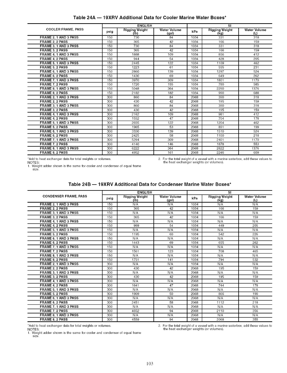
Table 24A -- 19XRV Additional Data for Cooler Marine Water Boxes*
COOLER FRAME, PASS
FRAME 2, 1 AND 3 PASS
FRAME 2, 2 PASS
FRAME 3_ 1AND 3 PASS
FRAME 3, 2 PASS
FRAME 4, 1 AND 3 PASS
FRAME 4, 2 PASS
FRAME 5, 1 AND 3 PASS
FRAME 5, 2 PASS
FRAME 6, 1 AND 3 PASS
FRAME 6, 2 PASS
FRAME 7, 1 AND 3 PASS
FRAME 7, 2 PASS
FRAME 8, 1 AND 3 PASS
FRAME 8, 2 PASS
FRAME 2, 1 AND 3 PASS
FRAME 2, 2 PASS
FRAME 3, 1 AND 3 PASS
FRAME 3, 2 PASS
FRAME 4, 1 AND 3 PASS
FRAME 4, 2 PASS
FRAME 5, 1 AND 3 PASS
FRAME 5, 2 PASS
FRAME 6, 1 AND 3 PASS
FRAME 6, 2 PASS
FRAME 7, 1 AND 3 PASS
FRAME 7, 2 PASS
FRAME 8, 1 AND 3 PASS
FRAME 8, 2 PASS
peig (Ib)
150 730
150 365
150 730
150 365
150 1888
150 944
150 2448
150 1223
150 2860
150 1430
150 3970
150 1720
150 5048
150 2182
300 860
300 430
300 860
300 430
300 2162
300 1552
300 2655
300 1965
300 3330
300 2425
300 5294
300 4140
300 6222
300 4952
*Add to heat exchanger data for total weights or volumes.
NOTES:
1. Weight adder shown is the same for cooler and condenser of equal frame
size.
ENGLISH SI
Rigging Weight Water Volume Rigging Weight Water Volume
(L)
318
159
318
159
412
2O5
462
231
(gal) kPa (kg)
84 1034 331
42 1034 166
84 1034 331
42 1034 166
109 1034 856
54 1034 428
122 1034 1109
61 1034 555
139 1034 1297
69 1034 649
309 1034 1801
155 1034 780
364 1034 2290
182 1034 990
84 2068 390
42 2068 195
84 2068 390
42 2068 195
109 2068 981
47 2068 704
122 2068 1204
53 2068 891
139 2068 1510
58 2068 1100
309 2068 2401
146 2068 1878
364 2068 2822
161 2068 2246
524
262
1170
585
1376
688
318
159
318
159
412
178
462
199
524
218
1170
553
1376
609
2, For the total weight of a vessel with a marine waterbox, add these values to
the heat exchanger weights (or volumes),
Table 24B -- 19XRV Additional Data for Condenser Marine Water Boxes*
CONDENSER FRAME, PASS
FRAME 2, 1 AND 3 PASS
FRAME 2, 2 PASS
FRAME 3, 1AND 3 PASS
FRAME 3, 2 PASS
FRAME 4, 1 AND 3 PASS
FRAME 4, 2 PASS
FRAME 5, 1 AND 3 PASS
FRAME 5, 2 PASS
FRAME 6, 1 AND 3 PASS
FRAME 6, 2 PASS
FRAME 7, 1 AND 3 PASS
FRAME 7, 2 PASS
FRAME 8, 1 AND 3 PASS
FRAME 8, 2 PASS
FRAME 2, 1 AND 3 PASS
FRAME 2, 2 PASS
FRAME 3, 1 AND 3 PASS
FRAME 3, 2 PASS
FRAME 4, 1 AND 3 PASS
FRAME 4, 2 PASS
FRAME 5, 1 AND 3 PASS
FRAME 5, 2 PASS
FRAME 6, 1 AND 3 PASS
FRAME 6, 2 PASS
FRAME 7, 1 AND 3 PASS
FRAME 7, 2 PASS
FRAME 8, 1 AND 3 PASS
FRAME 8, 2 PASS
ENGLISH
Rigging Weight
psig !lb)
150 N/A
150 365
150 N/A
150 365
150 N/A
150 989
150 N/A
150 1195
150 N/A
150 1443
150 N/A
150 1561
150 N/A
150 1751
300 N/A
300 430
300 N/A
300 430
300 N/A
300 1641
300 N/A
300 1909
300 N/A
300 2451
300 N/A
300 4652
300 N/A
300 4559
*Add to heat exchanger data for total weights or volumes.
NOTES:
1. Weight adder shown is the same for cooler and condenser of equal frame
size.
SI
Water Volume kPa Rigging Weight
N/A 1034 N/A
42 1034 166
N/A 1034 N/A
42 1034 166
N/A 1034 N/A
54 1034 449
N/A 1034 N/A
60 1034 542
N/A 1034 N/A
69 1034 655
N/A 1034 N/A
123 1034 708
N/A 1034 N/A
141 1034 794
N/A 1034 N/A
42 2068 195
N/A 2068 N/A
42 2068 195
N/A 2068 N/A
47 2068 744
N/A 2068 N/A
50 2068 866
N/A 2068 N/A
58 2068 1112
N/A 2068 N/A
94 2068 2110
N/A 2068 N/A
94 2068 2068
Water Volume
tL)
N/A
159
N/A
159
N/A
2O5
N/A
226
N/A
262
N/A
465
N/A
532
N/A
159
N/A
159
N/A
178
N/A
190
N/A
218
N/A
386
N/A
385
2, For the total weight of a vessel with a marine waterbox, add these values to
the heat exchanger weights (or volumes),
103
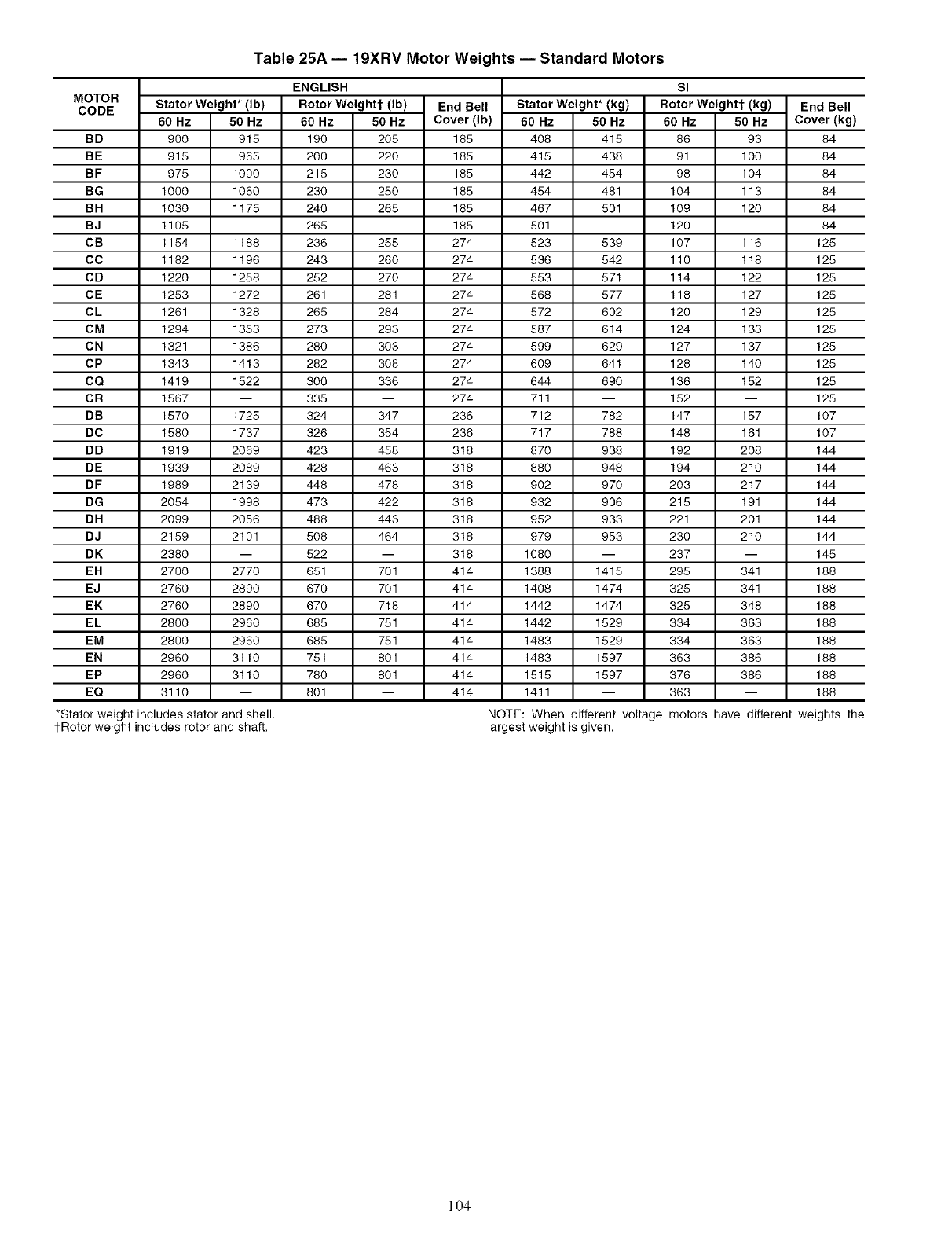
MOTOR
CODE
BD 900
BE 915
BF 975
BG 1000
BH 1030
BJ 1105
CB 1154
CC 1182
CD 1220
CE 1253
CL 1261
CM 1294
CN 1321
CP 1343
CO 1419
CR 1567
DB 1570
DC 1580
DD 1919
DE 1939
DF 1989
DG 2054
DH 2099
DJ 2159
DK 2380
ER 2700
EJ 2760
EK 2760
EL 2800
EM 2800
EN 2960
EP 2960
EO 3110
*Stator weight includes stator and shell.
tRotor weight includes rotor and shaft.
Table 25A -- 19XRV Motor Weights -- Standard Motors
StatorWeight*(Ib)
60 Hz 50 Hz
915
965
1000
1060
1175
1188
1196
1258
1272
1328
1353
1386
1413
1522
1725
1737
2069
2089
2139
1998
2056
2101
2770
2890
2890
2960
2960
3110
3110
ENGLISH
Rotor Weightt (Ib)
60 Hz 50 Hz
190 205
200 220
215 230
230 250
240 265
265
236 255
243 260
252 270
261 281
265 284
273 293
280 303
282 308
300 336
335
324 347
326 354
423 458
428 463
448 478
473 422
488 443
508 464
522
651 701
670 701
670 718
685 751
685 751
751 801
780 801
801
End Bell Stator Weight* (kg)
60 Hz 50 Hz
408 415
415 438
442 454
454 481
467 501
501
523 539
536 542
553 571
568 577
572 602
587 614
599 629
609 641
644 690
711
712 782
717 788
870 938
880 948
902 970
932 906
952 933
979 953
1080
1388 1415
1408 1474
1442 1474
1442 1529
1483 1529
1483 1597
1515 1597
1411
NOTE: When different voltage
largest weightis given.
End Bell
60 Hz Cover(kg)
86 93 84
91 100 84
98 104 84
104 113 84
109 120 84
120 -- 84
107 116 125
110 118 125
114 122 125
118 127 125
120 129 125
124 133 125
127 137 125
128 140 125
136 152 125
152 -- 125
147 157 107
148 161 107
192 208 144
194 210 144
203 217 144
215 191 144
221 201 144
230 210 144
237 -- 145
295 341 188
325 341 188
325 348 188
334 363 188
334 363 188
363 386 188
376 386 188
363 -- 188
motors have different weights the
Cover(Ib)
185
185
185
185
185
185
274
274
274
274
274
274
274
274
274
274
236
236
318
318
318
318
318
318
318
414
414
414
414
414
414
414
414
SI
Rotor Weightt (kg)
50 Hz
104
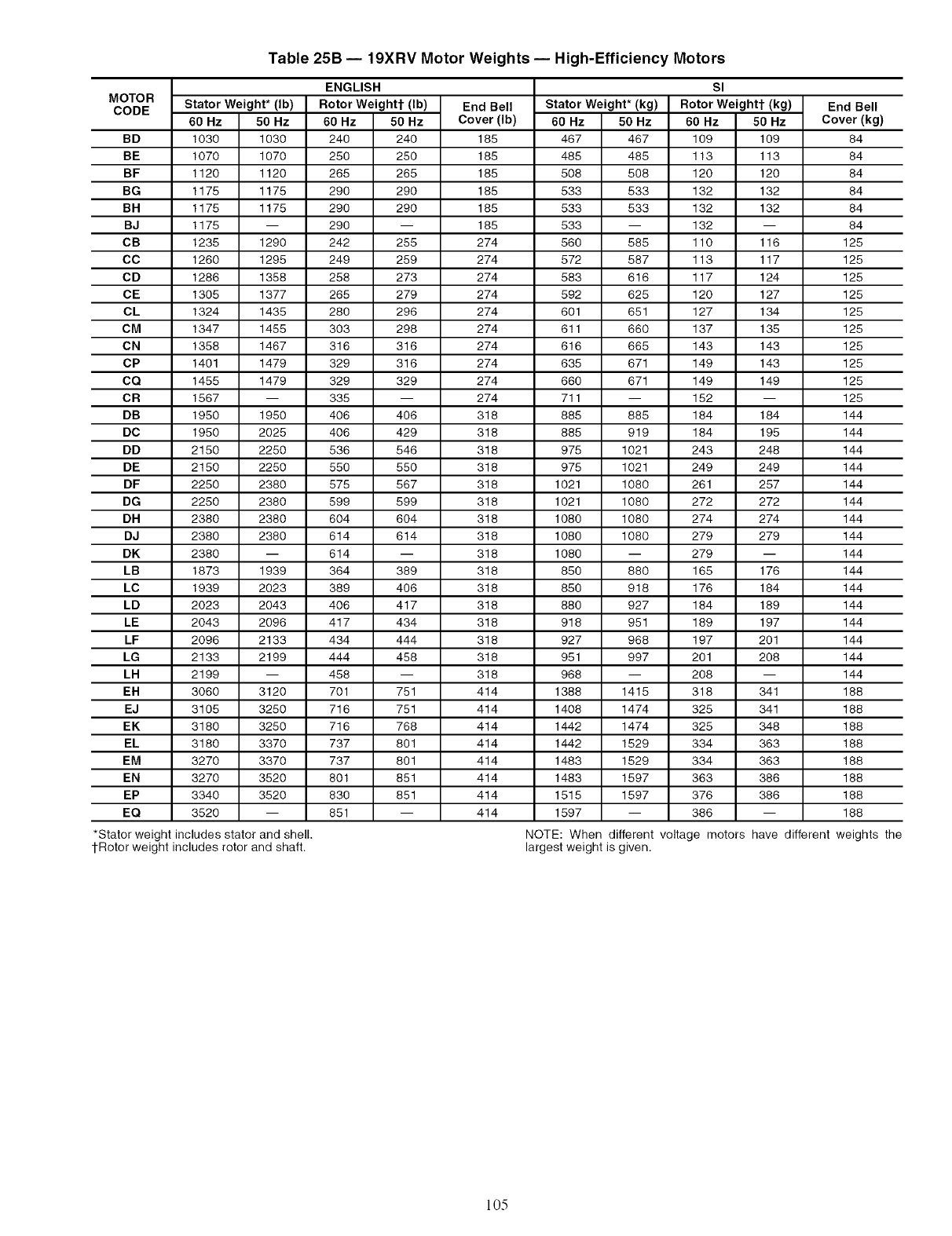
MOTOR
CODE
Table 25B -- 19XRV Motor Weights -- High-Efficiency Motors
Stator
60 Hz
BD 1030
BE 1070
BF 1120
BG 1175
BH 1175
BJ 1175
CB 1235
CC 1260
CD 1286
CE 1305
CL 1324
CM 1347
CN 1358
CP 1401
CQ 1455
CR 1567
DB 1950
DC 1950
DD 2150
DE 2150
DF 2250
DG 2250
DH 2380
DJ 2380
DK 2380
LB 1873
LC 1939
LD 2023
LE 2043
LF 2096
LG 2133
LH 2199
ER 3060
EJ 3105
EK 3180
EL 3180
EM 3270
EN 3270
EP 3340
EQ 3520
*Stator weightincludes stator and shell.
tRotor weightincludesrotor and shaft.
Weight*(Ib)
50 Hz
1030
1070
1120
1175
1175
1290
1295
1358
1377
1435
1455
1467
1479
1479
1950
2025
2250
2250
2380
2380
2380
2380
1939
2023
2043
2096
2133
2199
3120
3250
3250
3370
3370
3520
3520
ENGLISH
Rotor Weightt (Ib)
60 Hz 50 Hz
240 240
250 250
265 265
290 290
290 290
290
242 255
249 259
258 273
265 279
280 296
303 298
316 316
329 316
329 329
335
406 406
406 429
536 546
550 550
575 567
599 599
604 604
614 614
614
364 389
389 406
406 417
417 434
434 444
444 458
458
701 751
716 751
716 768
737 801
737 801
801 851
830 851
851
End Bell
Cover (Ib)
185
185
185
185
185
185
274
274
274
274
274
274
274
274
274
274
318
318
318
318
318
318
318
318
318
318
318
318
318
318
318
318
414
414
414
414
414
414
414
414
StatorWeight*(kg)
60 Hz 50 Hz
467 467
485 485
508 508
533 533
533 533
533
560 585
572 587
583 616
592 625
601 651
611 660
616 665
635 671
660 671
711
885 885
885 919
975 1021
975 1021
1021 1080
1021 1080
1080 1080
1080 1080
1080
850 880
850 918
880 927
918 951
927 968
951 997
968
1388 1415
1408 1474
1442 1474
1442 1529
1483 1529
1483 1597
1515 1597
1597
60 Hz
109
113
120
132
132
132
110
113
117
120
127
137
143
149
149
152
184
184
243
249
261
272
274
279
279
165
176
184
189
197
201
2O8
318
325
325
334
334
363
376
386
SI
Rotor Weightt (kg)
50 Hz
109
113
120
132
132
116
117
124
127
134
135
143
143
149
184
195
248
249
257
272
274
279
176
184
189
197
201
2O8
341
341
348
363
363
386
386
NOTE: When different voltage motors have
largest weight is given.
End Bell
Cover (kg)
84
84
84
84
84
84
125
125
125
125
125
125
125
125
125
125
144
144
144
144
144
144
144
144
144
144
144
144
144
144
144
144
188
188
188
188
188
188
188
188
different weights the
105
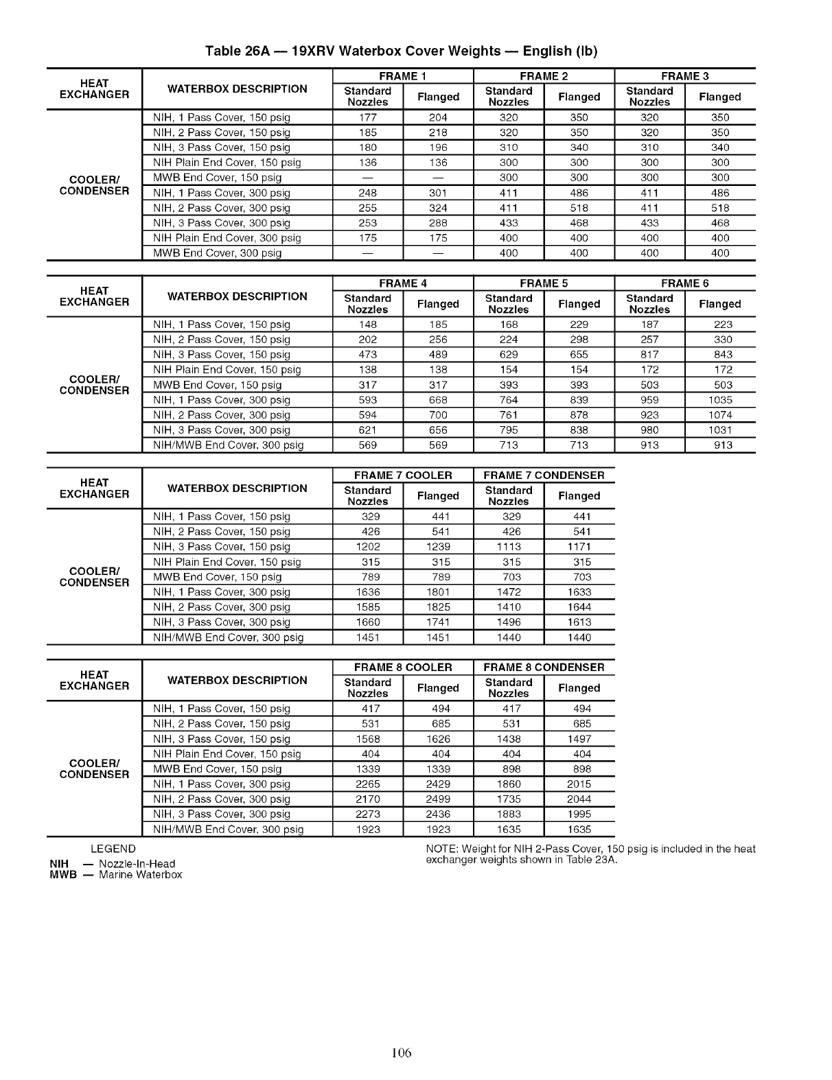
HEAT
EXCHANGER
Table 26A -- 19XRV Waterbox Cover Weights -- English (Ib)
WATERBOX DESCRIPTION
NIH, 1 Pass Cover, 150 psig
NIH, 2 Pass Cover, 150 psig
NIH, 3 Pass Cover, 150 psig
NIH Plain End Cover, 150 psig
COOLER/ MWB End Cover, 150 psig
CONDENSER NIH, 1 Pass Cover, 300 psig
NIH, 2 Pass Cover, 300 psig
NIH, 3 Pass Cover, 300 psig
NIH Plain End Cover, 300 psig
MWB End Cover, 300 psig
FRAME 1
Standard
Nozzles Flanged
177 204
185 218
180 196
136 136
248 301
255 324
253 288
175 175
FRAME 2
Standard
Nozzles
32O
32O
310
3OO
3OO
411
411
433
4OO
4OO
Standard
Nozzles Flanged
320 350
320 350
310 340
300 300
300 300
411 486
411 518
433 468
400 400
400 400
FRAME 3
Flanged
35O
35O
34O
3OO
3OO
486
518
468
4OO
4OO
HEAT
EXCHANGER WATERBOX DESCRIPTION
NIH, 1 Pass Cover, 150 psig
NIH, 2 Pass Cover, 150 psig
NIH, 3 Pass Cover, 150 psig
NIH Plain End Cover, 150 psig
COOLER/ MWB End Cover, 150 psig
CONDENSER NIH, 1 Pass Cover, 300 psig
NIH, 2 Pass Cover, 300 psig
NIH, 3 Pass Cover, 300 psig
NIH/MWB End Cover, 300 psig
FRAME 4
Standard
Nozzles Flanged
148 185
202 256
473 489
138 138
317 317
593 668
594 700
621 656
569 569
FRAME 5
Standard
Nozzles
187
257
817
172
503
959
923
980
913
Standard
Nozzles Flanged
168 229
224 298
629 655
154 154
393 393
764 839
761 878
795 838
713 713
FRAME 6
Flanged
223
330
843
172
503
1035
1074
1031
913
HEAT
EXCHANGER WATERBOX DESCRIPTION
NIH, 1 Pass Cover, 150 psig
NIH, 2 Pass Cover, 150 psig
NIH, 3 Pass Cover, 150 psig
NIH Plain End Cover, 150 psig
COOLER/ MWB End Cover, 150 psig
CONDENSER
NIH, 1 Pass Cover, 300 psig
NIH, 2 Pass Cover, 300 psig
NIH, 3 Pass Cover, 300 psig
NIH/MWB End Cover, 300 psig
FRAME 7 COOLER
Standard
Nozzles Flanged
329 441
426 541
1202 1239
315 315
789 789
1636 1801
1585 1825
1660 1741
1451 1451
Standard
Nozzles
329
426
1113
315
7O3
1472
1410
1496
1440
FRAME 7 CONDENSER
Flanged
441
541
1171
315
7O3
1633
1644
1613
1440
HEAT
EXCHANGER WATERBOX DESCRIPTION
NIH, 1 Pass Cover, 150 psig
NIH, 2 Pass Cover, 150 psig
NIH, 3 Pass Cover, 150 psig
NIH Plain End Cover, 150 psig
COOLER/ MWB End Cover, 150 psig
CONDENSER
NIH, 1 Pass Cover, 300 psig
NIH, 2 Pass Cover, 300 psig
NIH, 3 Pass Cover, 300 psig
NIH/MWB End Cover, 300 psig
LEGEND
NIH -- Nozzle-lmHead
MWB -- Marine Waterbox
FRAME 8 COOLER
Standard
Nozzles Flanged
417 494
531 685
1568 1626
404 404
1339 1339
2265 2429
2170 2499
2273 2436
1923 1923
FRAME 8 CONDENSER
Standard
Nozzles Flanged
417 494
531 685
1438 1497
404 404
898 898
1860 2015
1735 2044
1883 1995
1635 1635
NOTE:Weightfor NIH 2-Pass Cover, 150 psigisincludedinthe heat
exchanger weights showninTable 23A.
106
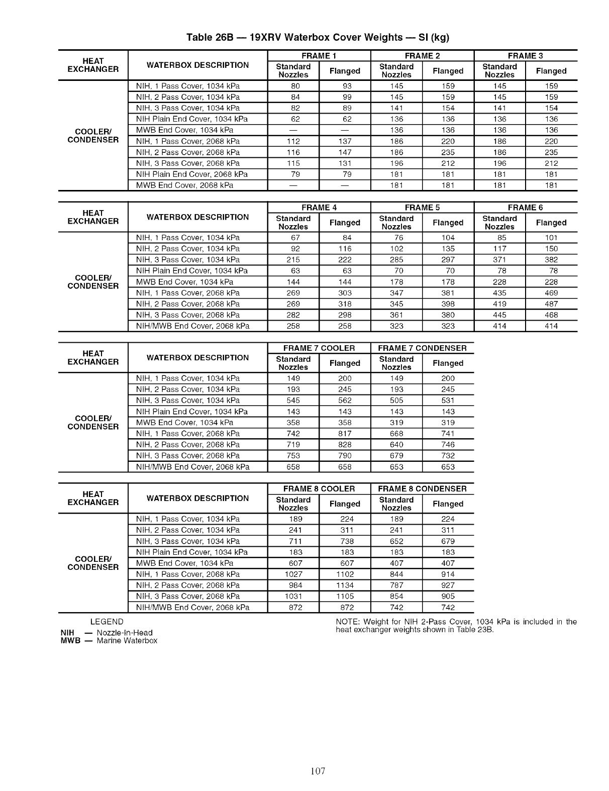
HEAT
EXCHANGER
Table 26B -- 19XRV Waterbox Cover Weights -- Sl (kg)
WATERBOX DESCRIPTION
NIH, 1 Pass Cover, 1034 kPa
NIH, 2 Pass Cover, 1034 kPa
NIH, 3 Pass Cover, 1034 kPa
NIH Plain End Cover, 1034 kPa
COOLER/ MWB End Cover, 1034 kPa
CONDENSER NIH, 1 Pass Cover, 2068 kPa
NIH, 2 Pass Cover, 2068 kPa
NIH, 3 Pass Cover, 2068 kPa
NIH Plain End Cover, 2068 kPa
MWB End Cover, 2068 kPa
FRAME1
Standard
Nozzles Flanged
80 93
84 99
82 89
62 62
112 137
116 147
115 131
79 79
FRAME 2
Standard
Nozzles
145
145
141
136
136
186
186
196
181
181
Standard
Nozzles Flanged
145 159
145 159
141 154
136 136
136 136
186 220
186 235
196 212
181 181
181 181
FRAME 3
Flanged
159
159
154
136
136
22O
235
212
181
181
HEAT
EXCHANGER WATERBOX DESCRIPTION
NIH, 1 Pass Cover, 1034 kPa
NIH, 2 Pass Cover, 1034 kPa
NIH, 3 Pass Cover, 1034 kPa
NIH Plain End Cover, 1034 kPa
COOLER/
CONDENSER MWB End Cover, 1034 kPa
NIH, 1 Pass Cover, 2068 kPa
NIH, 2 Pass Cover, 2068 kPa
NIH, 3 Pass Cover, 2068 kPa
NIH/MWB End Cover, 2068 kPa
FRAME4
Standard
Nozzles Flanged
67 84
92 116
215 222
63 63
144 144
269 303
269 318
282 298
258 258
FRAME 5
Standard
Nozzles
85
117
371
78
228
435
419
445
414
Standard
Nozzles Flanged
76 104
102 135
285 297
70 70
178 178
347 381
345 398
361 380
323 323
FRAME 6
Flanged
101
150
382
78
228
469
487
468
414
HEAT
EXCHANGER WATERBOX DESCRIPTION
NIH, 1 Pass Cover, 1034 kPa
NIH, 2 Pass Cover, 1034 kPa
NIH, 3 Pass Cover, 1034 kPa
NIH Plain End Cover, 1034 kPa
COOLER/
CONDENSER MWB End Cover, 1034 kPa
NIH, 1 Pass Cover, 2068 kPa
NIH, 2 Pass Cover, 2068 kPa
NIH, 3 Pass Cover, 2068 kPa
NIH/MWB End Cover, 2068 kPa
FRAME 7 COOLER
Standard
Nozzles Flanged
149 200
193 245
545 562
143 143
358 358
742 817
719 828
753 790
658 658
Standard
Nozzles
149
193
5O5
143
319
668
640
679
653
FRAME 7 CONDENSER
Flanged
2OO
245
531
143
319
741
746
732
653
HEAT
EXCHANGER WATERBOX DESCRIPTION
NIH, 1 Pass Cover, 1034 kPa
NIH, 2 Pass Cover, 1034 kPa
NIH, 3 Pass Cover, 1034 kPa
NIH Plain End Cover, 1034 kPa
COOLER/
CONDENSER MWB End Cover, 1034 kPa
NIH, 1 Pass Cover, 2068 kPa
NIH, 2 Pass Cover, 2068 kPa
NIH, 3 Pass Cover, 2068 kPa
NIH/MWB End Cover, 2068 kPa
LEGEND
NIH -- Nozzle-In-Head
MWB -- Marine Waterbox
FRAME 8 COOLER
Standard
Nozzles Flanged
189 224
241 311
711 738
183 183
607 607
1027 1102
984 1134
1031 1105
872 872
FRAME 8 CONDENSER
Standard
Nozzles Flanged
189 224
241 311
652 679
183 183
407 407
844 914
787 927
854 905
742 742
NOTE:Weightfor NIH 2-Pass Cover, 1034 kPa is included in the
heatexchanger weights showninTable 23B.
107
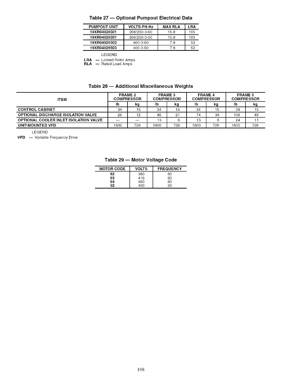
Table 27 -- Optional Pumpout Electrical Data
PUMPOUT UNIT
19XR04026501
19XR04026501
19XR04026502
19XR04026503
LEGEND
LRA
RLA
VOLTS-PH-Hz MAX RLA LRA
208/230-3-60 15.8 105
208/230-3-50 15.8 105
460-3-60 7.8 52
400-3-50 7.8 52
-- Locked Rotor Amps
-- Rated Load Amps
ITEM
Table 28 -- Additional Miscellaneous Weights
FRAME 2 FRAME 3 FRAME 4
COMPRESSOR COMPRESSOR COMPRESSOR
Ib kg
34 15
26 12
1600 726
Ib kg
34 15
46 21
13 6
1600 726
Ib kg
34 15
74 34
13 6
1600 726
CONTROL CABINET
OPTIONAL DISCHARGE ISOLATION VALVE
OPTIONAL COOLER INLET ISOLATION VALVE
UNIT-MOUNTED VFD
LEGEND
VFD -- Variable Frequency Drive
FRAME 5
COMPRESSOR
Ib kg
34 15
108 49
24 11
1600 726
Table 29 -- Motor Voltage Code
MOTOR CODE VOLTS FREQUENCY
62 380 60
63 416 60
64 460 60
52 400 50
108
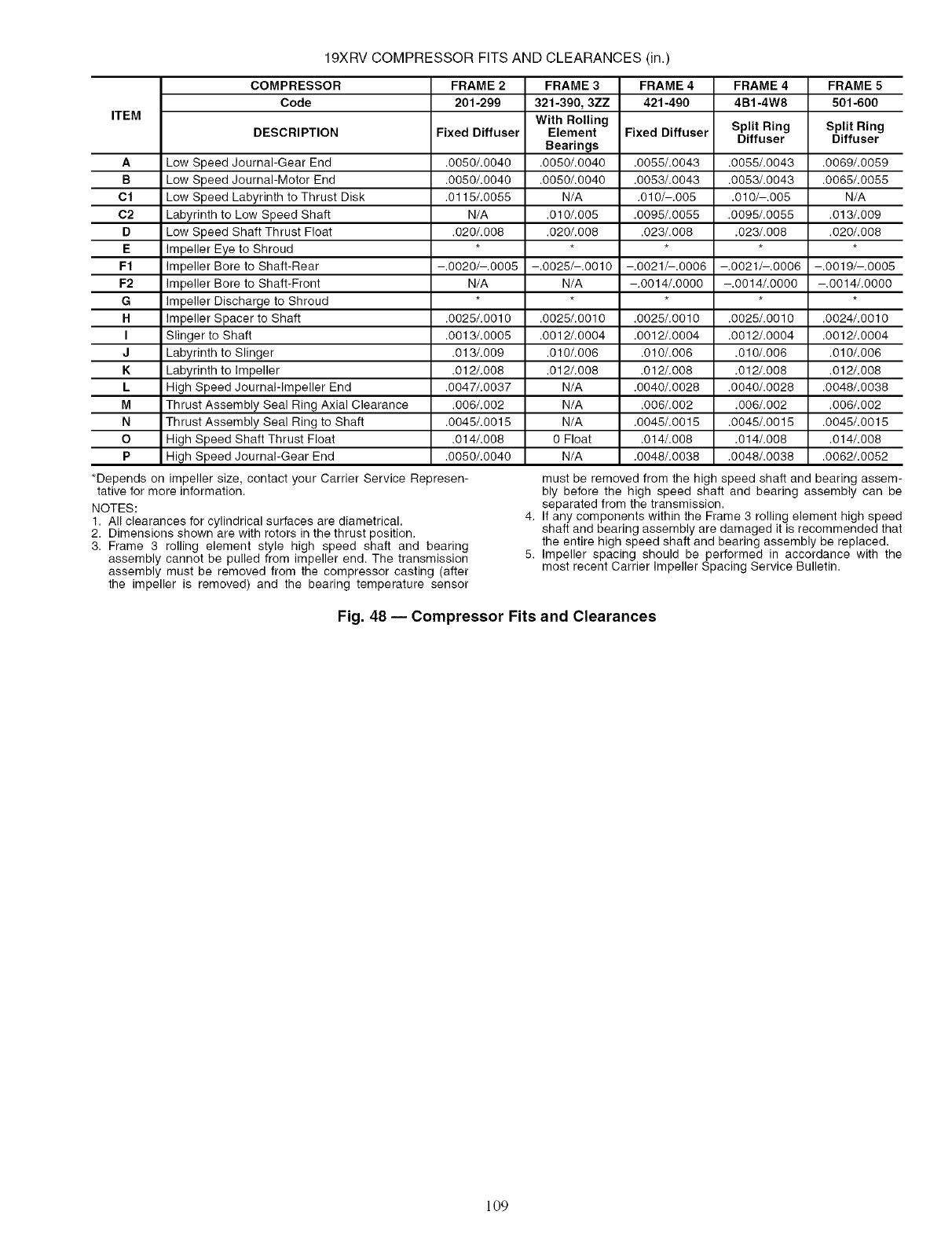
19XRV COMPRESSOR FITS AND CLEARANCES (in.)
COMPRESSOR FRAME 2 FRAME 3 FRAME 4 FRAME 4 FRAME 5
Code 201-299 321-390, 3ZZ 421-490 4B1-4W8 501-600
ITEM With Rolling Split Ring Split Ring
DESCRIPTION Fixed Diffuser Element Fixed Diffuser Diffuser Diffuser
Bearings
A Low Speed Journal-Gear End .0050/.0040 .0050/.0040 .0055/.0043 .0055/.0043 .0069/.0059
B Low Speed Journal-Motor End .0050/.0040 .0050/.0040 .0053/.0043 .0053/.0043 .0065/.0055
Cl Low Speed Labyrinth to Thrust Disk .0115/.0055 N/A .010/-.005 .010/-.005 N/A
C2 Labyrinth to Low Speed Shaft N/A .010/.005 .0095/.0055 .0095/.0055 .013/.009
D Low Speed Shaft Thrust Float .020/.008 .020/.008 .023/.008 .023/.008 .020/.008
E Impeller Eye to Shroud
Ff Impeller Bore to Shaft-Rear -.0020/-.0005 -.0025/-.0010 -.0021/-.0006 -.0021/-.0006 -.0019/-.0005
F2 Impeller Bore to Shaft-Front N/A N/A -.0014/.0000 -.0014/.0000 -.0014/.0000
G Impeller Discharge to Shroud
H Impeller Spacer to Shaft .0025/.0010 .0025/.0010 .0025/.0010 .0025/.0010 .0024/.0010
I Slinger to Shaft .0013/.0005 .0012/.0004 .0012/.0004 .0012/.0004 .0012/.0004
J Labyrinth to Slinger .013/.009 .010/.006 .010/.006 .010/.006 .010/.006
K Labyrinth to Impeller .012/.008 .012/.008 .012/.008 .012/.008 .012/.008
L High Speed Journal-Impeller End .0047/.0037 N/A .0040/.0028 .0040/.0028 .0048/.0038
M Thrust Assembly Seal Ring Axial Clearance .006/.002 N/A .006/.002 .006/.002 .006/.002
N Thrust Assembly Seal Ring to Shaft .0045/.0015 N/A .0045/.0015 .0045/.0015 .0045/.0015
O High Speed Shaft Thrust Float .014/.008 0 Float .014/.008 .014/.008 .014/.008
P High Speed Journal-Gear End .0050/.0040 N/A .0048/.0038 .0048/.0038 .0062/.0052
*Depends on impeller size, contact your Carrier Service Re 3resen-
tative for more information.
NOTES:
1. All clearances for cylindrical surfaces are diametrical.
2. Dimensions shown are with rotors in the thrust position.
3. Frame 3 rolling element style high speed shaft and bearing
assembly cannot be pulled from impeller end. The transmission
assembly must be removed from the compressor casting (after
the impeller is removed) and the bearing temperature sensor
4.
5.
must be removed from the high speed shaft and bearing assem-
bly before the high speed shaft and bearing assembly can be
separated from the transmission.
If any components within the Frame 3 rolling element high speed
shaft and bearing assembly are damaged it is recommended that
the entire high speed shaft and bearing assembly be replaced.
Impeller spacing should be performed in accordance with the
most recent Carrier Impeller Spacing Service Bulletin.
Fig. 48 -- Compressor Fits and Clearances
109
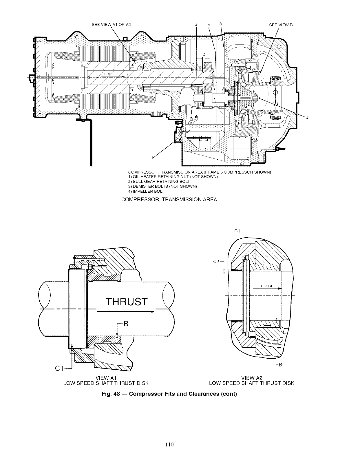
SEE VIEW A10RA2 A 2 3 SEE VIEW B
COMPRESSOR, TRANSMISSION AREA (FRAME 5 COMPRESSOR SHOWN)
1) OIL HEATER RETAINING NUT (NOT SHOWN)
2) BULLGEAR RETAINING BOLT
3) DEMISTER BOLTS (NOT SHOWN)
4) IMPELLER BOLT
COMPRESSOR, TRANSMISSION AREA
THRUST
Cl
VIEW A1
LOW SPEED SHAFT THRUST DISK VIEW A2
LOW SPEED SHAFT THRUST DISK
Fig. 48 -- Compressor Fits and Clearances (cont)
110
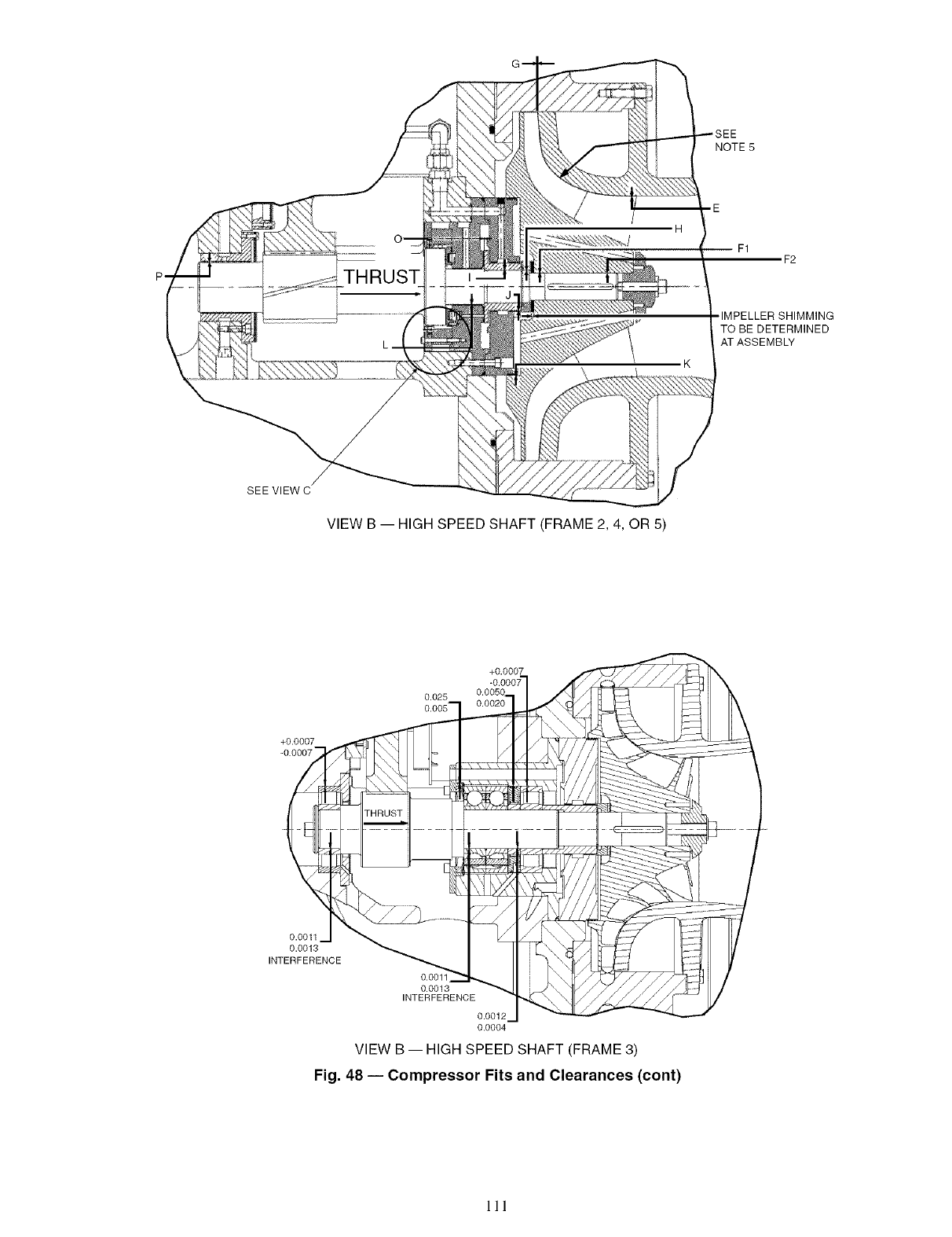
NOTE5
F2
IMPELLER SHIMMING
TO BE DETERMINED
AT ASSEMB_
SEE VIEW C
VIEW B -- HIGH SPEED SHAFT (FRAME 2, 4, OR 5)
+0.0007
0.025
+0.0007
-0.0007-
0.0011
0.0013
INTERFERENCE
0.0011
0.0013
INTERFERENCE
0.0012
0.0004
VIEW B -- HIGH SPEED SHAFT (FRAME 3)
Fig. 48 -- Compressor Fits and Clearances (cont)
III
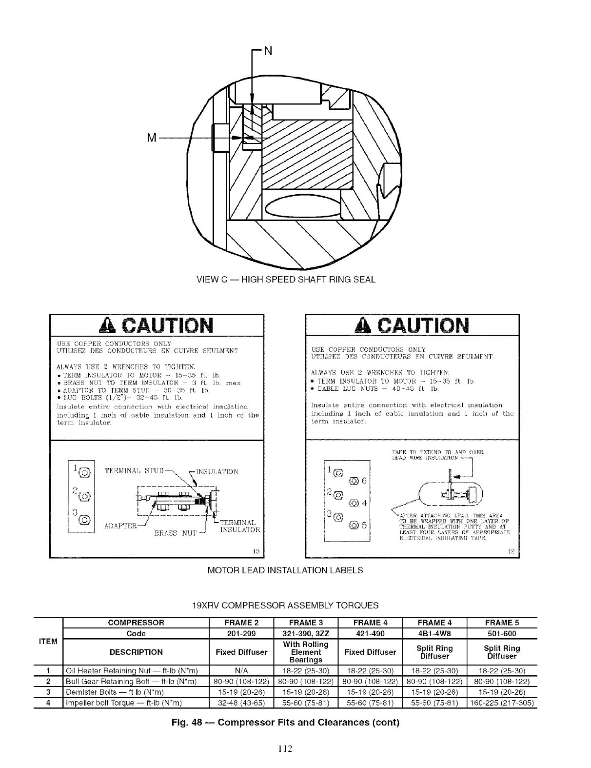
\
VIEW C -- HIGH SPEED SHAFT RING SEAL
ACAUTION
USE COPPER CONDtJC'I'0RS0NY
UTII,]SEZ DES CONDUCTEURS EN CUIVRE SEU,MENT
ALWAYS USE 2 WRENCHES T0 TIGHTEN,
• TERM INSULATOR TO M0'10R 15+35 it+ lb
• BRASS NUT T0 TERM INSULATOR ....3ft. lb. max
• ADAPTOR TO TERM STUD - 3035 ft [b,
• LUG BOLTS (1/2") 32 45 ft. [b.
Insulate +,ntir'r+ cnnnection with eler_Ir]eai iz_slllation
including 1 inch of cable insulation and 1 inch of @Je
term insulator.
2@
3©
TERMINAL STUD- _ _-INSULATION
r....... -'\4---I
A DAD'p]_N? _ ,1 L'-TERMINAL
........ _A_NSS NU]" ] INSIJLATOR
13
CAUTION
USE COPPER CONDUCTORS ONLY
UTII,ISEZDES CONDUCTEUBS EN CUIVRE SEUI,MENT
ALWAYS USE 2 WRENCHES TO T]GHTEN,
o TERM INSULATOR TO MOTOR 15 35 ft Ib
o CABLE LUG NUTS ..... ft.lb.
Insulate entire connection with electrical insulation
including 1 inch of (¸:able insula±,io_ and I i_ch of the
term insulator.
1© @6
@4
8@ @,5
TAPETO EXTENDTO AND OVER
LEAD }_TRE |NS[H,A lCN
<-_-'A?+[ER ATTACHrNE LEAD, 'tHiS AREA
TO BE WRAPPED?_THONELAYFROF
TIIERNALINSULATIONPUTTY AND AT
I[,EAS'] FOUR LAYERS OF APPROPRIATE
ELECTRICAL INSULATING TAPE
MOTOR LEAD INSTALLATION LABELS
19XRV COMPRESSOR ASSEMBLY TORQUES
COMPRESSOR FRAME 2 FRAME 3 FRAME 4 FRAME 4 FRAME 5
Code 201-299 321=390, 3ZZ 421-490 4B1-4W8 501-600
ITEM With Rolling Split Ring Split Ring
DESCRIPTION Fixed Diffuser Element Fixed Diffuser
Bearings Diffuser Diffuser
1 Oil Heater Retaining Nut- ft-lb (N'm) N/A 18-22 (25-30) 18-22 (25-30) 18-22 (25-30) 18-22 (25-30)
2 Bull Gear Retaining Bolt-- ft-lb (N'm) 80-90 (108-122) 80-90 (108-122) 80-90 (108-122) 80-90 (108-122) 80-90 (108-122)
3 Demister Bolts -- ft Ib (N'm) 15-19 (20-26) 15-19 (20-26) 15-19 (20-26) 15-19 (20-26) 15-19 (20-26)
4 Impeller bolt Torque -- ft-lb (N'm) 32-48 (43-65) 55-60 (75-81) 55-60 (75-81) 55-60 (75-81) 160-225 (217-305)
Fig. 48 -- Compressor Fits and Clearances (cont)
ll2
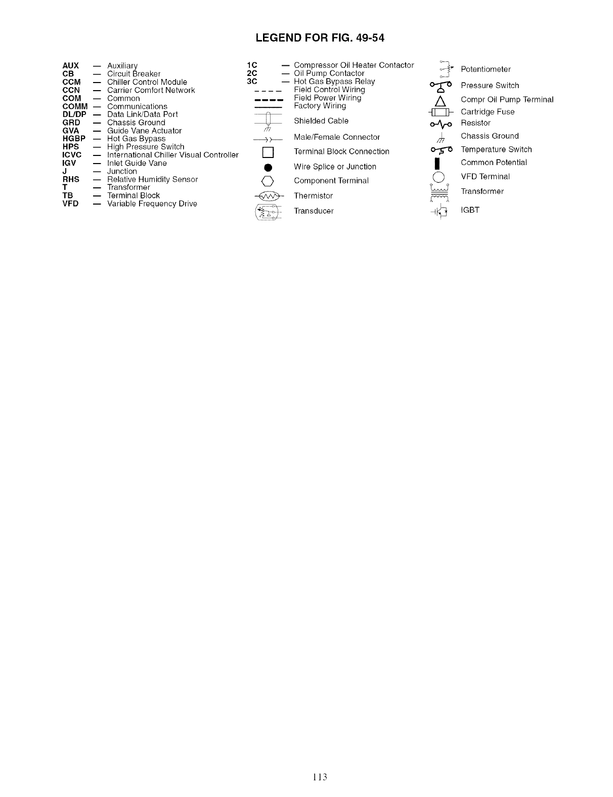
LEGEND FOR FIG. 49-54
AUX --
CB --
CCM --
CCN --
COM --
COMM --
DUDP --
GRD --
GVA --
HGBP --
HPS --
ICVC --
IGV --
J
RHS --
T
TB
VFD --
Auxiliary 1C
Circuit Breaker 2C
Chiller Control Module 3C
Carrier Comfort Network
Common
Communications
Data Link/Data Port
Chassis Ground
Guide Vane Actuator
Hot Gas Bypass _ >---
High Pressure Switch
International Chiller Visual Controller I I
Inlet Guide Vane
Junction •
Relative Humidity Sensor <_
Transformer
Terminal Block @
Variable Frequency Drive
Compressor Oil Heater Contactor
Oil Pump Contactor
Hot Gas Bypass Relay
Field Control Wiring
Field Power Wiring
Factory Wiring
Shielded Cable
Male/Female Connector
Terminal Block Connection
Wire Splice or Junction
Component Terminal
Thermistor
Transducer
A
o-Aro
I
©
Potentiometer
Pressure Switch
Compr Oil Pump Terminal
Cartridge Fuse
Resistor
Chassis Ground
Temperature Switch
Common Potential
VFD Terminal
Transformer
IGBT
113
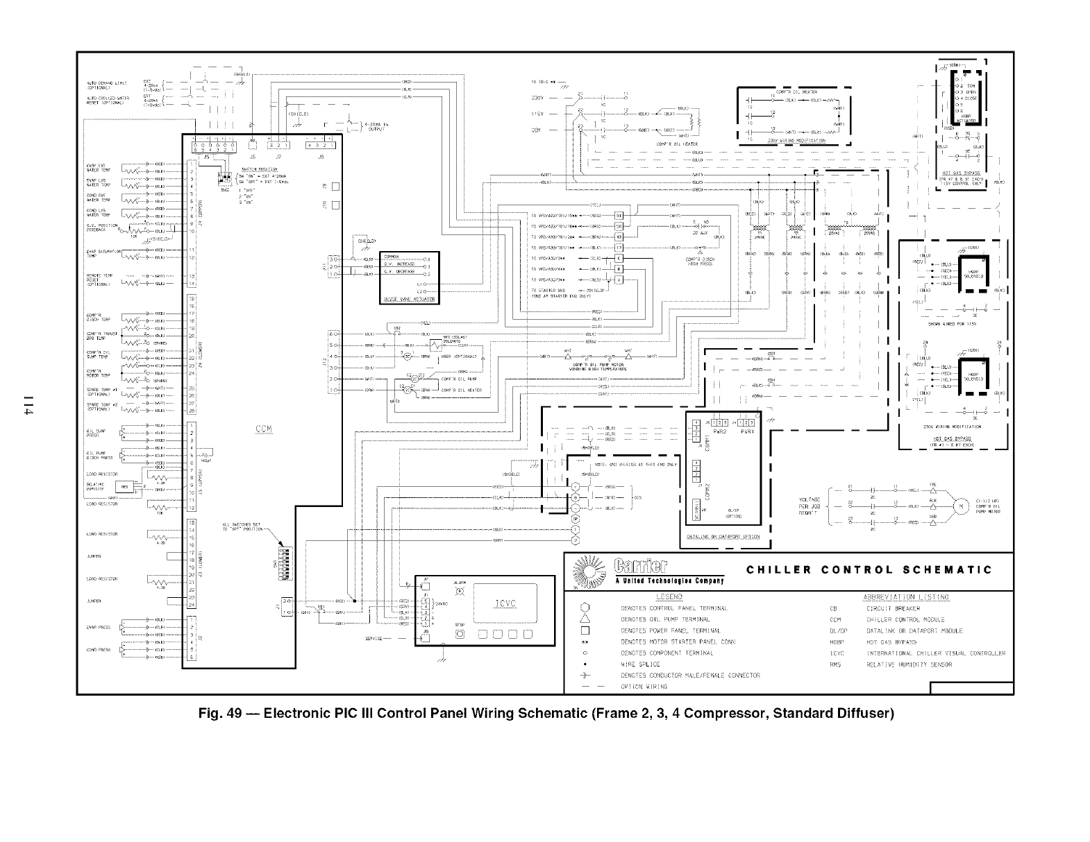
_ DE_OTE_ COND_=CTO__ALE/F_E_4_L_ ¢ON_ECTOR
Fig. 49 -- Electronic PIC III Control Panel Wiring Schematic (Frame 2, 3, 4 Compressor, Standard Diffuser)
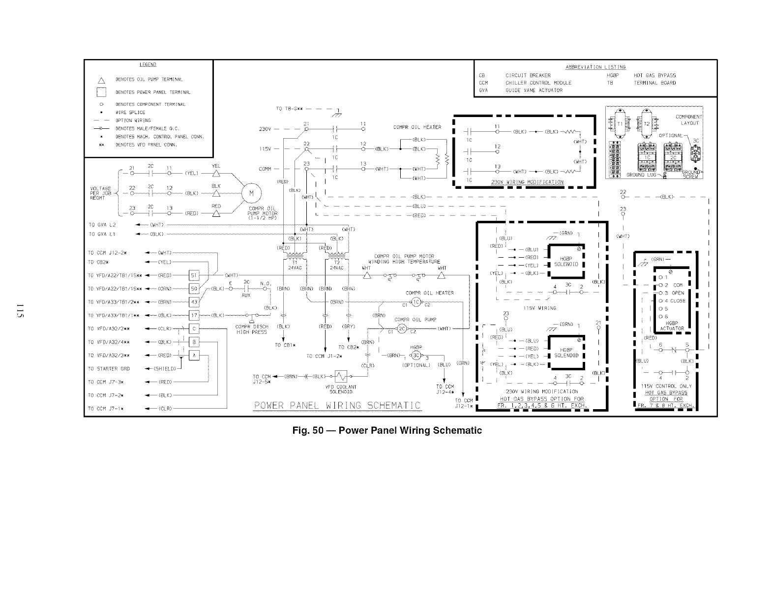
lEGEND
DENOTES OIL PUMP TERMINA
DENOTES POWER PANEL TERMINAL
0 D_NOTES COMPONLNT TERMINAL
W_RE SP_CE
O_T_ON W_R_NG
_ DENOTES MALE/F_MALE _,C,
DENOTES MACH, CONTROL PANEL CONN,
• _ DENOTES VFD PANE_ CONN,
COMPR OiL HEALER
lYEL
VBLi_ABE _ 22 2B 12 BL_
X
PER JOB -- O_ _ 0 (BLK) --
REGMT '
10 GVA L2 _ (WHT)
tO GVA L (BLK)
TO CCM J12 2_ (WHI}
COMPR OiL
PUMP MOTOR
(1 i/2 HP)
(RED)
L_
GUIDE VANE ACTUAI©R
TO VFD/AB2/2_
iO VFD/A32/4m_
TO VFD/A32/3_
TO STARTER ORD
TO CCM J?_3_
TO CCH J7_2_
TO CCH J?_i_
(RED)
(BLK)
{CLR)
COMPR DISCH (BLK)
HIGH PRES5
TO CB/_
(WHT) I
J12-5_
POWER PANEL
(BLK)
I (BLU)
[............................. (RED) ..................
(W_T) (W_T)
ABBREV At ON LISTING
CB C RCUIT BREAKER HGBP HOT GAS BYPASS
DDM (:HILLER CONTROL MODULE TB TERMINAL BOARD
_v_ GD,OEVINE ACP_',TGU__t__. --
i i i i i i i - _ COMPONENTi
LAYOUT i
/C (BLK) + (B K) _N _ OPTIONAL i
c ii
/_ _ K) _A/\
/C 230 WIRING ODIFC_FION
i i i--i'i i i i
KBLK> I
I
r IIIIII I
(GRN) I
I ( U) /, • )
i _:0 (LU) t I I
p _ { D) HD_P II_ I II I
I _ (YL) _ SOLENOIDI I III/// I I
i(Y) " -_eK)--III I o I III
IIII(LK) _) 3C 2 (BIi I K) I 1 _2 co,,i I I
II os II
I2sc)VWIBNGrII IiI° BGBPII I
(_R_,) 1 I
I LIA#_A_DRII '
I _ (BLU) !I iiiii -
II,<ED) ._LL)_ _R) II
II _ (RE_)I HGBP lI, '_,_I '
I I _ (YE) _ SOL NOID I I_L) CB_K)I
•IlBV CONIRO ONY
I_V_'ABB I
TO CB2_ iIHGBP
(CLR) (OPTIONAL) (BLU) (Oi
VFD COOLANT TO CCM
SOLENOID Ji2 4m
TO CCM
W1RING 5CHENATIC ,'_,
O tt o
Fig. 50 -- Power Panel Wiring Schematic
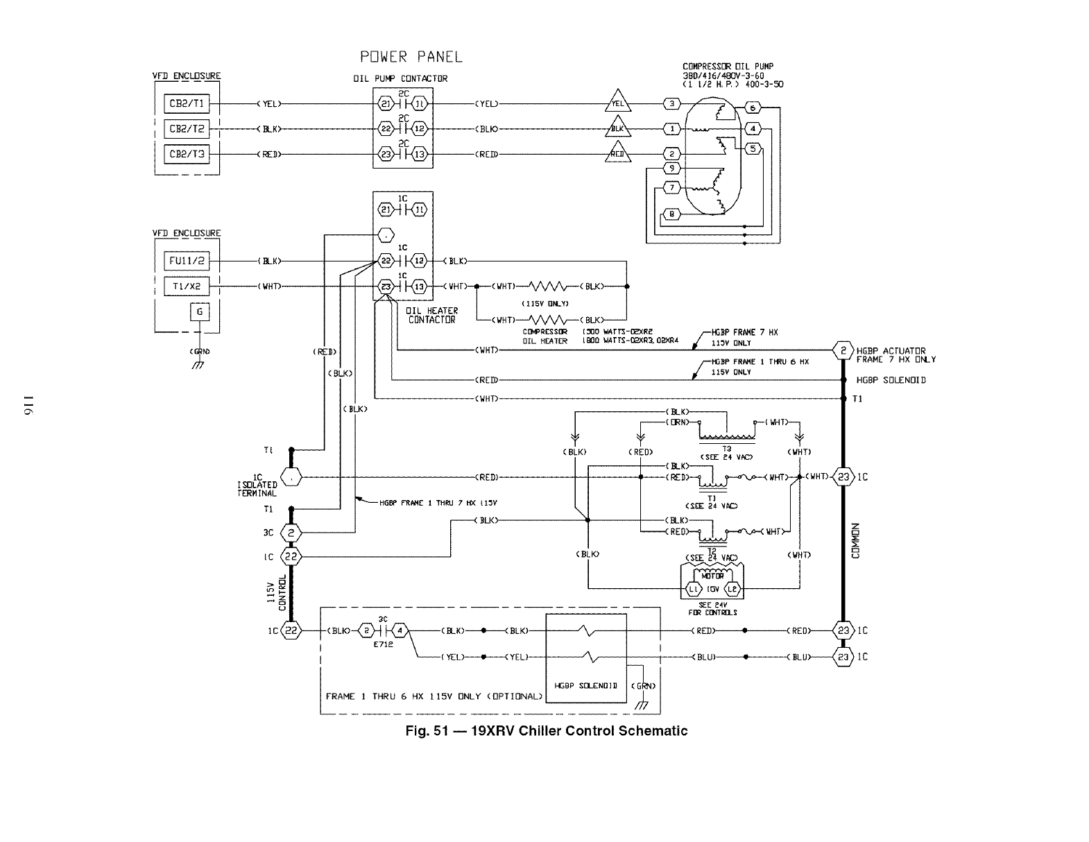
VFD ENCLOSURE
I
I _ BLK)
VF-D ENCLOSURE
I
I _I I (WHT)
PDWER PANEL
OIL PUMP CDNTACTOR
(_-12_[J_- --( Y EL.)
(RZD)
T[ _(B
=tXTE
J_
J<)
(BLK)
1C
I-<D
-0 Ic
10
OIL HEATER
CONTACTOR
COHPRESSI]R OIL PUNP
3BDI4161480V-3-60
(1 t12 H, P.) 400-3-._0
BLK)
(l15v ONLY} >___J
L(WHT)_( Bt._
COMPRESSOR [:_30wArTs-D2XR£
OILHEA_ tmO varr_-mxR_.0Z_R4
-(WHT)
-(RED)
FiGDP FR_IE 7HX
115V ONLY
HO_P FR,_HE 1 [HRU 6HX
115V ONLY
<WHT)
(BLK)
[_HINAL
TI
,c<>
(RED)
I'_'---HSBP FR,_IE 1 THRU 7HX tl_V
F _LI<)
_C
-(BLK) -<_ _ (I).-K)----e-----(BLK )--
g71a _'_ (YZL)----e-----< YEL)--
FRAME ITHRU 6 HX 115V ONLY (I]PTIONAL)
(B_K>------l
T _ T
(RED) "_ (WHT)
(SEE _4 VKD
(RED IIHT)-
II.K)---- 1
I _-----------(RE O_>--_ W HI">.-
(BLK)
l*IGgP SE]L£NO]D ] (/_L_)I
SEE _4V
FOR C_rTROL$
(RED) $
(BLU)
L(WHT>-_
(WHT)
I
HGBP ACTUATOR
< _FRAME 7 HX ONLY
HGBP SOLENOI D
TI
>lc
Ig
Fig. 51 -- 19XRV Chiller Control Schematic
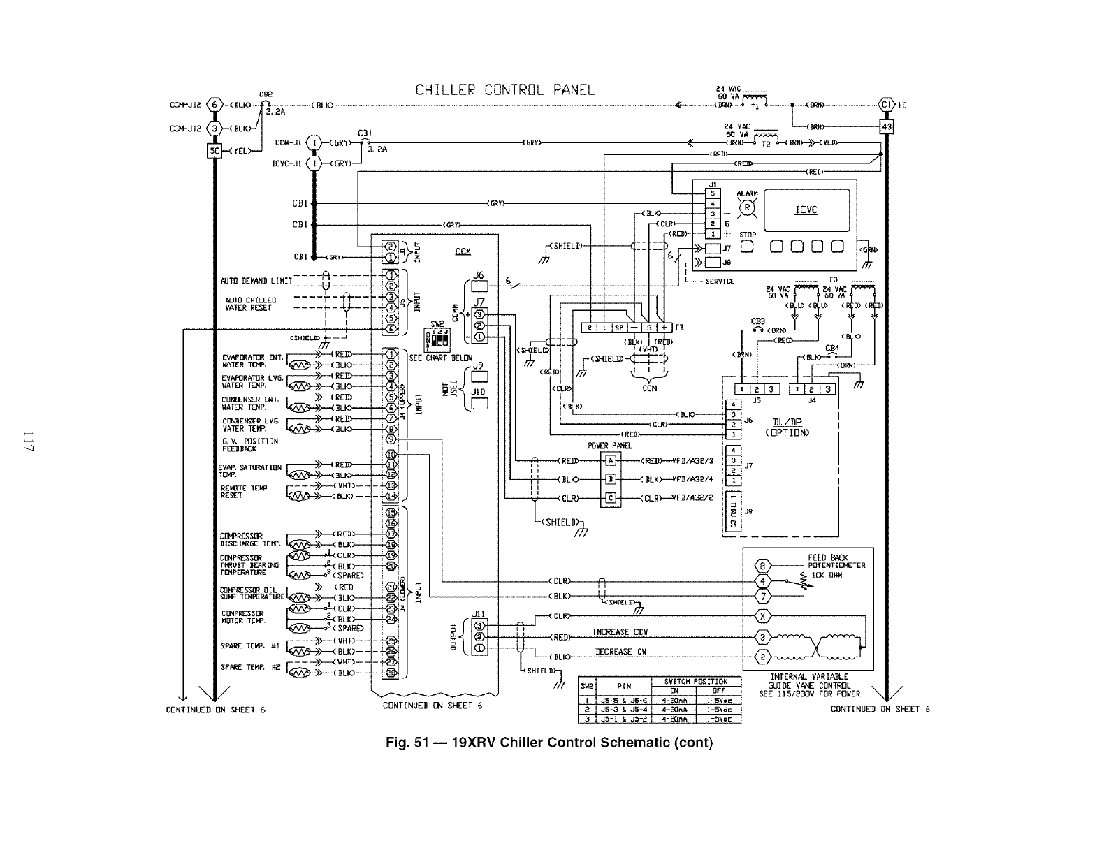
_JI2
CBe
--(DL C_I
IEVC-Jt i( _yi--J '
CB]
CB1 q
_UIO _E_ND L[MIIZZZSZZZZ Z
....
.... r-'V---
i $
l t
(_HIELIO/._---J
EvaPm_r_ rm, V---_'_ RED)--
E_CA_RATCIR LV& _)---( RED)+---+
uaTm T_:Np, _)----< _I.I<)-_
CORI_ZN_ Bl, _REII_
wATERIZNP. _>----< _LFO_
VATER TEMP, _>---( SL.KZ_-_
G,V+ _S[TION
FEE]JI_C_K
EVAP,,SATUma_TION_>_( R{I))_
+a,e. _ ELK>---
REm+E+E++ F_.--->_ v#_>--
COMPRESSB_ _>---< RZ_>-----
DI$CHN_GE I[MI:+_>----( BLK)----
CIIMP_SOR _CLR_.....--
tHRUST ]_F_AR[NO BLK)---
r_P_r_g SPARE)
++ "fZN_RAI'UR[ L_>--.-( +LK)-----
MI]'fl]RTEMP+ _LK _--'--"
'_-'_:_( SPARD
SPARE "TEMP.#] F --i>>--'(VHT)--
_>--< BLK)---
FEE-->>--<v_--
/
CONTINLEI) ON SHEEI 6
2A
CHILLER CONTROL
((_RY)
CcM
J6
SEE CHART _EU]W
+°i+
Ji
PANEL _+_c.i
24 V_£ I_RN)
VA
+d_ZS)
(_I_Y) J1 _/_L_RM --
ICVC
I I F<Ra>-_T_ -k s'_op -- |
I II"I IseI-I_I÷Ir_ _mN>_ 1 (_K_ I
'_ISLO) (S_4"I)+C_4
I I F '_" _-r I I I _---_oml ---I
¢_: I_ _ ' _ iLI ]_li._=ii,
(C_)-- _J6 _DLIDP
I (R_> _ (OPTION)
@
@
-@
..@
Jll
++
CONTINUE_ ZI_ SHEET 6
_VER P_
_----1_------(REl))_ (REIi)--VF_ IA3 _/3
_'(SHIELII b
'IC
FEED BACK
P_i TZNTI_TERC(<ONH
INFERNAL VARIABLE
GUIDE V#C_E CONTROL /
SEE I15/230V FOR R3WER "x
CONTINUED ON SI_EE'T6
Fig. 51 -- lgXRV Chiller Control Schematic (cont)
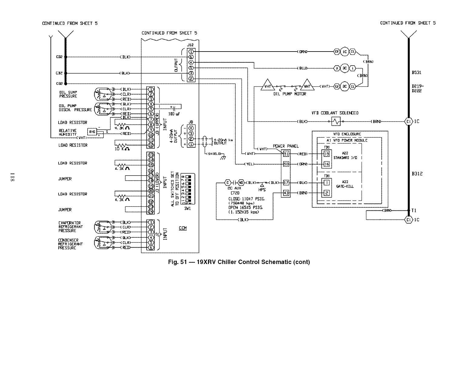
_INUED FROM _EET 5
\/
c_ (BLK)
C_E (gLK)
C_
_-.-._>---< _LK_
OIL SUMP [_>---< CLR)----
PRESSURE _>---< RED>----
OIL PUMP _>--"( I_LK)-----
DISCH. PRESSURE [_'_>-'--<CLR}------
F----<_LK)--
LOAD RESISTOR I
_:.L_HVc IRHSF--'_$ ....
HLAMI]]]IY l.e_u>----
LOAD RESIS]OR
LOAD RESISTOR
JUMPER
LOAD RESISTOR
JUMPER
EVAP_ATOR _ BLK)-----
REFI_IOER_NT CLF_
PESSURE _>---( R_
CONDENSER t-_>__< CLR).._
REFR ]6ERANT
PRESSURE _>---( REI)>----
CONTINUED FROM SHET 5
CONTINUED FROM SHEET 5
J12
-i1
(3RN)
OIL PUMP MOll]R
YF11OODLANT SOLENOID
(BLK)------_,
SWI
"-PT-[4-_o_.,
_c aux HPS
ET_D r--_ _ 8_-
CLOSE:110_7 PSIG. I--
VFD ENCLOSURE
AI VFO PDWER MODULE
SIAND_RD]/0 ]
\/
B531
D_19-
D_
(BB',_ >IC
B31_
-----<_----- T1
>ic
Fig. 51 -- 19XRV Chiller Control Schematic (cont)
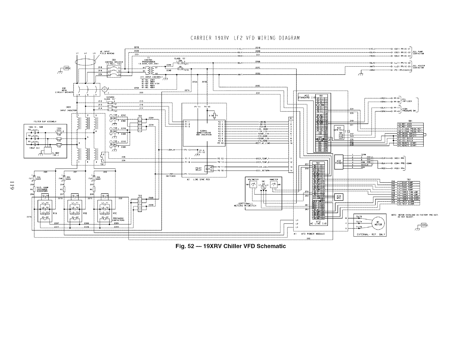
CARRIER 19XRV LF2 VFD WIRING DIAGRAM
_z_e
CR_D_
_SLK_
_Z_C
iAe_ec--
_e_ _osz__, c. oll _M_
Fig. 52 -- 19XRV Chiller VFD Schematic
--:,4] I1_:;;:,:::::::)'_......J
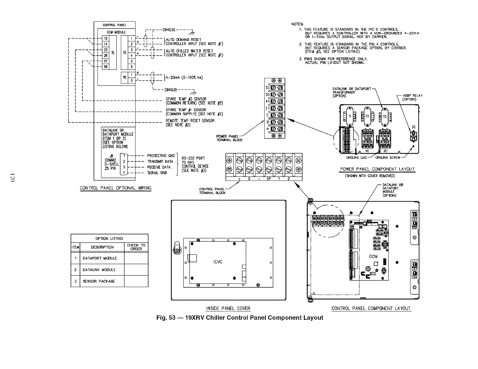
\\
]
I
_N_OL pANEL
¢CM MCOLAJ_
OATAUNK 13_
DATAPOR'[ MOOULE
ITI_ 1 OR2)
_E oPnON
]S_NO BELOW)
.... ,7,
----r"r-p-----"IAUIO DEMAND RESE1
-_-_-_--- _CONIROLLER INPUT (SEE NOTE #I)
__----IT--IAUmC_fLLEO_ATERRESE_
---,_--JCON_OLLERINPUT(SEENOTE_)
____ t___ 4--20r.A(O-IOOXkw)
_--(_) ....
SPARETEMP12 SENSOR
(COMMONREIURN)(SEENOTE#2)
SPARE _EMP #1 SmSOR
(COMMON SUPPLY] CSEE NOTE #2)
REMOIE 1EMP RESEI SENSOR
(_ N01Z /2)
4s_
C l(/h(//l
D-SHELLI _ I
CONTROL PANEL OPTIONAL W1RING
PROIECTIVE G_ID 1TRANSMW DATA
RECEIVE DATA I
RS-2Z2 PORT
fO BAS
CONIRQ__'_CE
(SEENOTE _)
÷ 0
03NTRCL pANEL j
TD_MINAL BLOCK
SP 1 2
OPTION USTING
CHECK TO
ITE_ DESCRIPTION ORDER
I DAIAPORT MOOULE
2DAIAUNK MOOULE
3SENSOR PA_KA(_£ °°°i
Icvc
e
o oo@
NOTE_
1. THIS FEATURE IS STANDARD IN THE PIC II OONTROLS,
BUT REQUIRE5 A CONIROLIJZR Y_TH ANON--GROUNDED 4-2OmA
OR 1-5Vdc OUTI_UT SIONAL NOT BY CARRIE_
2. _IS FEA_RE IS SIANDARD IN THE PIC II_ONTROLS,
BUT REOUIRES A SENSOR PACKAGE OPTION, BY CARRIER.
(ITEM #3, SEE OPTION LISTINO)
3. PINS SHOWN FOR REFERENCE ONLY.
ACTUAL PIN LAYOUT NOT SHOWN,
DATAUNK OR
TRANSFORMER
(OPIION) RELAY
(oRno.}
k
%
POWER PANEL COMPONENT LAYOUT
(_OWN _ COVERREMOVED)
INSIDE PANEL COVER CONTROL PANEL COMPONENT LAYOUT
Fig. 53 -- 19XRV Chiller Control Panel Component Layout
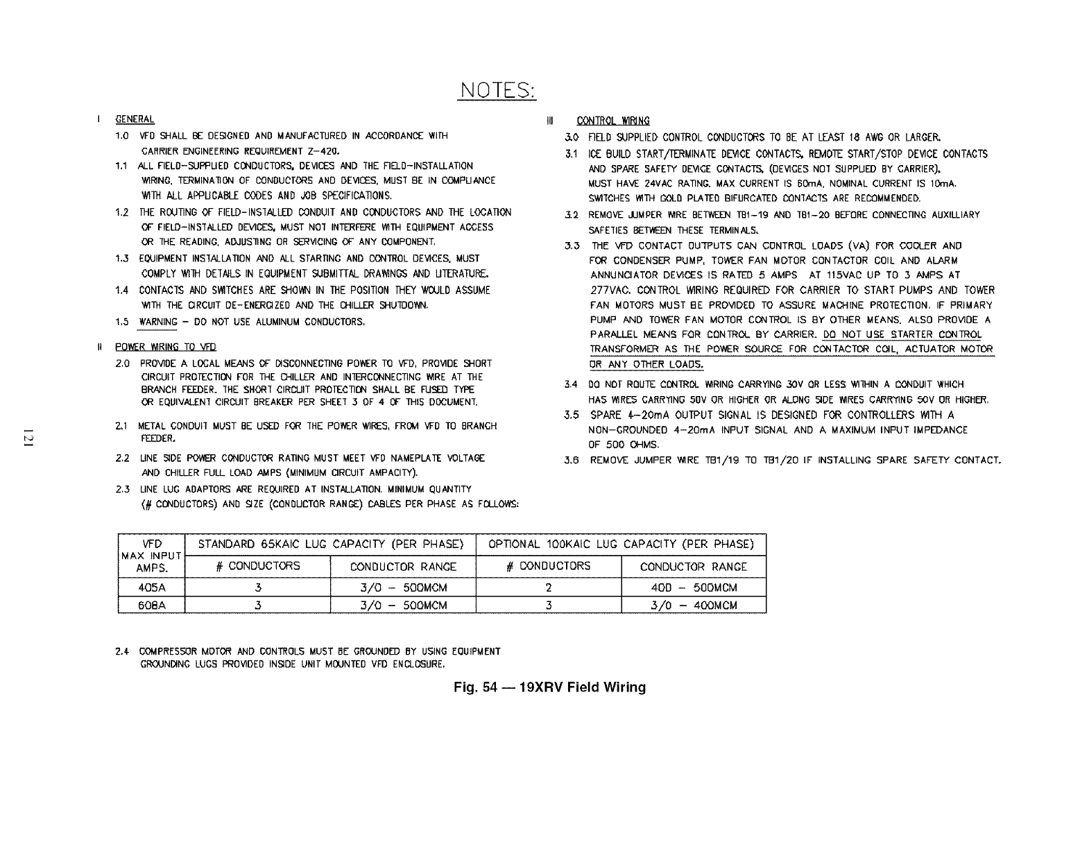
NOTES:
I GENERAL
1,0 VFD SHALL BE DESIGNED AND MANUFACTURED IN ACCORDANCE WITH
CARRIER ENGINEERING REQUIREMENT Z-420o
1,1 ALL FIELD-SUPPUED CONDUCTORS, DEVICES AND 'THE FIELD-INSTALLATION
WIRING, TI'3:_MINAIlON GF CONDUCTORS AND DEVICES, MUS'f 8E IN COMPUANCE
WITH ALL APPUCABLE CODES AND JOB SPECIFICATION&
1.2 THE ROUTING OF FIELD-INS'[ALLEDCONDUIT AND CONDUCTORS AND THE LOCA]ION
OF FIELD-INSTALLED DEVICES, MUST NOT INTERFERE WITH EQUIPMENT ACCESS
OR THE READING. AOdUSIlNG OR SERVICING OF ANY COMPONENT,
1,3 EQUIPMENT INSIALLATION AND ALL STARIINO AND CONTROL DEVICES. MUST
COMPLY _lll DEIAILS IN EQUIPMENT SUBMITTAL DRA_NOS AND UTERATURE.
1,4 CONrACIS AND S_TCHES ARE SHOWN IN THE POSITION IHEY WOULD ASSUME
WITH THE CIRCUIT DE-ENERGIZED AND THE CHILLER SHUII]OYvN.
1,5 NARNING - DO NOT USE ALUMINUM CONDUCTORS,
POWER _RING TO VFD
2,0 PROVIDE A LOCAL MEANS OF DISODNNEGTINO POWER TO VFD, PROVIDE SHORT
CIRCUIT PROTECTION FOR THE CHILLER AND INIERCONNECTING WIRE AT THE
BRANCH FEEDER. IHE SHOR'[ CIRCUIT PROfE'_:TIONSHALL BE FUSED TYPE
OR EQUiVALEN'f CIRCUIT BREAKDR PER SHEEI 3OF 4 OF THIS DOCUMEN'f.
Z,1 METAL CONDUII MUST BE USED FGR IHE POI_ER WIRES, FROVI VFD TO BRANCH
FEEDER.
2,2 UNE S@E POWER CONDUCTOR RATING MUST MEET VFD NAMEPLATE VOLTAGE
AND CHILLER FULL LOAD AMPS (MINIMUM CIRCUIT AMPACITY),
2,3 UNE LUG ADAPTORS ARE REQUIRED AT INSTALLATION. MINIMUM QUANTITY
(# CONDUCTORS) AND SIZE (CONDUCTOR RANGE) CABLES PER PHASE AS FI_I_I.OWS:
CONTROL _RI N(3
&O FIELD SUPPLIED CONTROL CONDUCTORS TO BE AT LEAST 18 A_ OR LAROEP,.
3.1 ICE BUILD START/ERMINATE DEVICE CONTACTS, REMOTE START/STOP DEVICE CONTACTS
AND SPARE SAFELY DEVICE CONTAC:TS_ (DEVICES NOI SUPPUED BY CARRIER],
MUST HAVE 24VAC RATING. MAX CURRENT IS BOrnA. NOMINAL CURRENT IS 10mA.
SWI'[CHES WITH C43LI)PLATED BIFURCATED C:ONIAC'ISARE RECX3MMENDED.
3.2 REMOVE ,.LIMPERWIRE BETWEEN TBI-Ig AND "fBI-20 BEFORE CDNNECI]N_ AUXILLIARY
SAFETIES BETV_ THESE TERMINALS.
3,_ TME VF'D CONTACT OUTPUTS CAN CONTROL LOADS (VA) FOR COOLER AND
FOR CONDENSER PUMP, TOWER FAN MOTOR CONTACTOR COIL AND ALARM
ANNUNCIATOR DEVICES IS RATED 5 AMPS AT 115VAC UP TO 3 AMPS AT
277VAC. CONTROL WIRING REOUIRED FOR CARRIER TO START PUMPS AND TOWER
FAN MOTORS MUST BE PROVIDED TO ASSURE MACHINE PROTECTION, IF PRIMARY
PUMP AND TOWER FAN MOTOR CONTROL IS BY OTHER MEANS. ALSO PROVIDE A
PARALLEL MEANS FOR DDNTROL BY CARRIER. DD NOT USE STARTER CONTROL
TRANSFORMER AS THE POWER SOURCE FOR CONTACTOR COIL, ACTUATOR MOTOR
DR ANT OTHER LOADS.
3.4 DO NOT ROUTE CONTROL WIRINI_CARRYING 3DV OR LESS WIIHIN A CONDUIT "NHICH
HAS WIRES 'CARRYING 50V OR HIGHER OR ALONG SIDE WIRES CARR'fING 50V OR HIGHER,
3.5 SPARE $-20mA OUTPUT SIGNAL IS DESIGNED FOR CONTROLLERS WITH A
NON--GROUNDEO 4-20mA INPUT SIGNAL AND A MAXIMUM INPUT IMPEDANCE
OF 500 OHMS.
3.6 REMOVE JUMPER WIRE TB1/19 TO TB1/20 IF INSTALLING SPARE SAFETY" CONTACT.
VFD STANDARD 65KAIC LUG CAPACITY (PER PHASE) OP_ONAL IOOKAIC LUG CAPACITY (PER PHASE)
MAX INPUT
AMPS. # CONDUCTORS CONDUCTOR RANGE # CONDUCTORS CONDUCTOR RANGE
405A 33/0 -500MCM 2 40D -500MCM
608A 3 3/0- 500MCM 3 3/0 - 400MCM
2.4- COMPRESSOR MOTOR AND CONTROLS MUST BE GROUND[I) BY USING EGUIPM[NT
GROUNDING LUGS PROVIDED INSIDE UNIT MOUNTED VFD ENCLOSURE,
Fig. 54 -- 19XRV Field Wiring
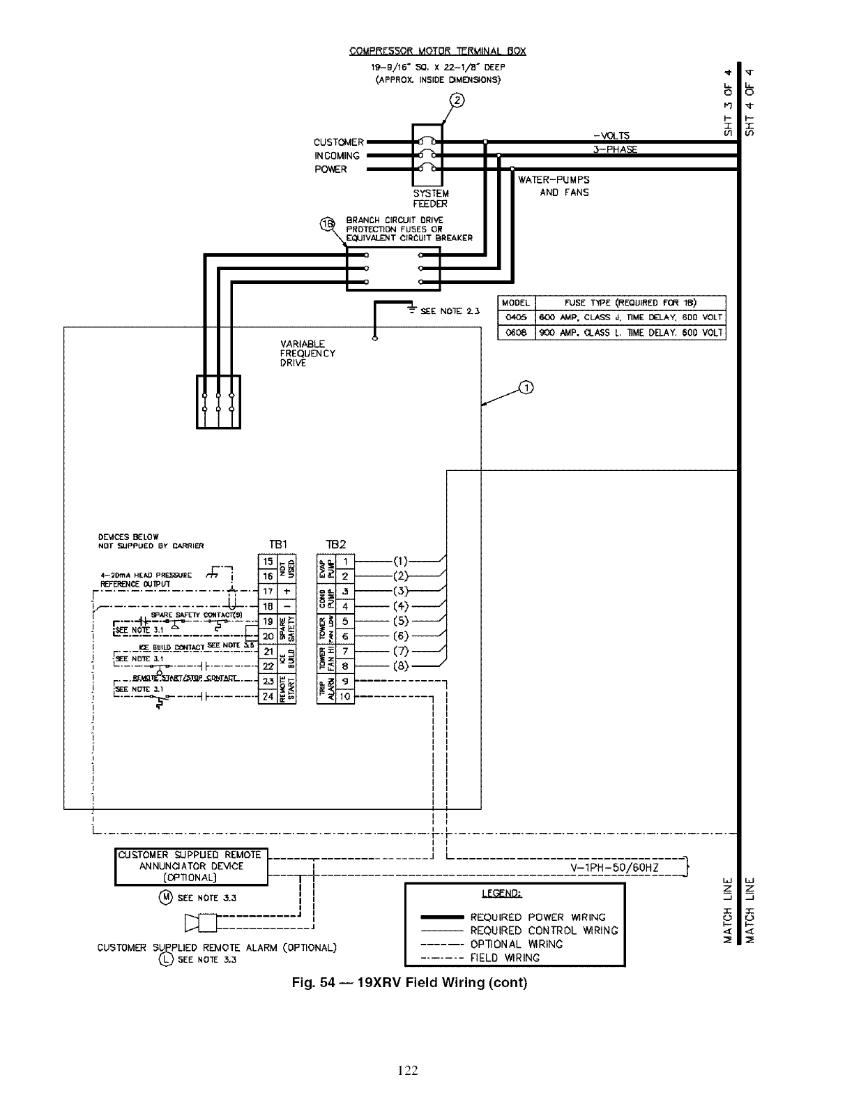
INCOMING
POWER WATER-PUMPS
AND FANS
[
VARIABLE
FREQUENCY
DRIVE
AMp, CLASS J, TIME DELAY, 6DD VOLT
AMP. _LA$S L'lIME DELAY. 600 VOL1
II
J V-1PH-50/60HZ ]
I REQUIRED POWER WIRING
-- REQUIRED CONTROL WIRING
...... OPTIONAL WIRINC
....... FIELD WIRING
CUSTOMER SUPPLIED RE_IOTE ALARM (OPTIONAL)
SEE NO_ ;5,3
Fig. 54 -- 19XRV Field Wiring (cont)
L_J
Z
:1=
122
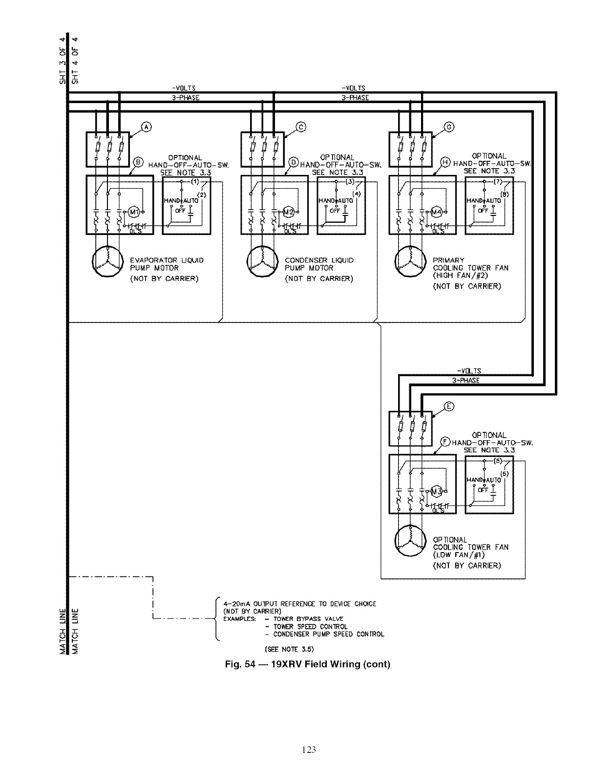
P3
F,- T"
-VOLTS -VOLTS
EVAPORATOR UCdJID
PUMP MOTOR
{NOT BY CARRIER)
CONDENSE]R LIQUID
PUMP MOTOR
(NOT BY CARRIER)
............ --7
L 4-20mA OUIPU1 REFERENCE TO DDACE CHOICE(NOT BY CAI:_IER)
....... [ _ aPeS: I TOWER BY_°ASS VAL_
-TDVVERSPEED CON]ROL
- ,CONDENSER PUMP SPEED CONTROL
(SEE NOTE 3.5)
PRIMARY
COOLING TOWER FAN
<HIOH FAN/#2)
(NOT BY CARRIER)
-VDL'fS
3-PHASE
OPTIONAL
'H AND- OFF- AUTC,--SW.
SEE NQTE 3.3
OP_ONAL
COOLING TOWER FAN
(LOW FANI_)
<NOT BY CARRIER)
Fig. 54 -- 19XRV Field Wiring (cont)
123
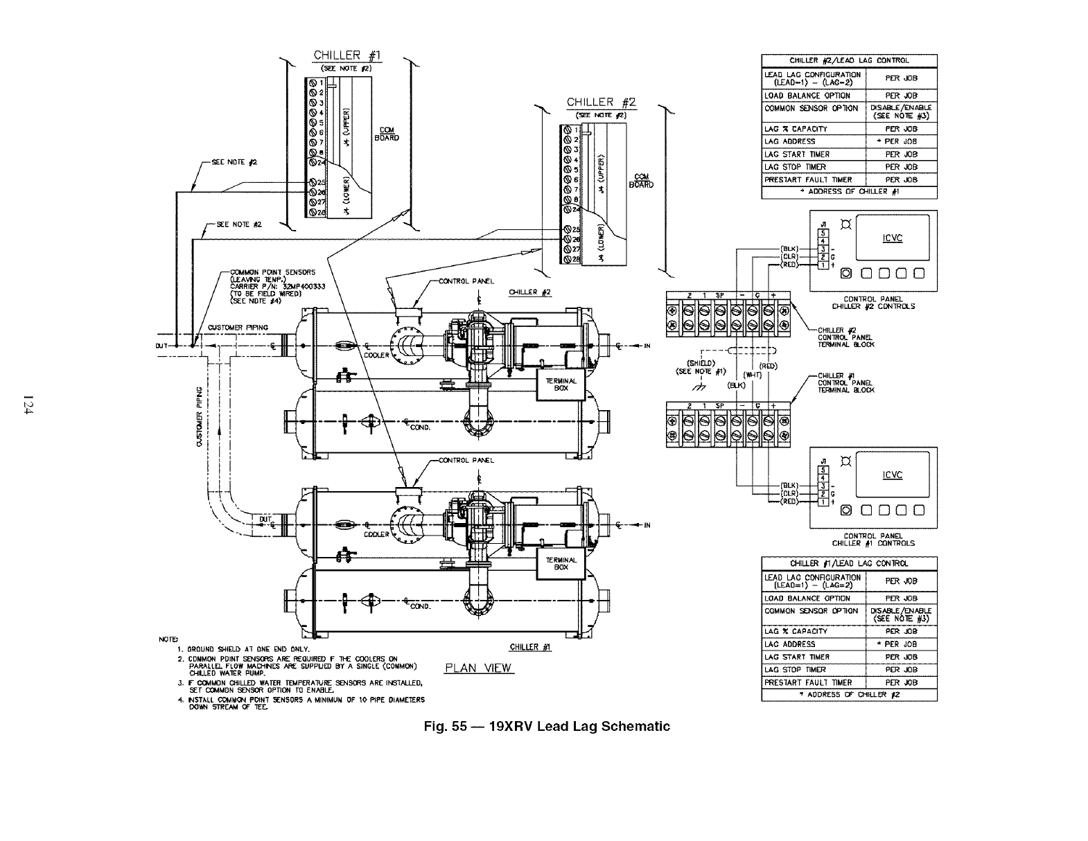
PANEL
....
1. OROUNO _41ELD AT ONE 1_4D ONLY.
D. COMMON POINT S_NSX_t_; ARE REQUIRED I= *g'fZ OODLES ON
PARA[tZL FLOW MAI:HINL_ ARE SUPPUE0 BY A SINGLE (C0XMON)
OAIJ*ED WA1ER PUMP_
3, FO3MMON CHILLED WATER T_P_ATURZ SEN_R'3 ARE INSTALLED,
_lr CC_MON _N_(LWR 0PI1ON _ ENABLE,
NST&[I COMMON P_AN'[ 5ENSOR5 A MINIMU_ OF 10 PIPE 01_METER5
DOWN STREAM OF TEE.
CHILLER //I
PLAN VIEW
Fig. 55- 19XRV Lead Lag Schematic
F---.<
(sN,a.o)
<_E NO__) (',,t,4r)
CHILLER _/LEAD LAG CONTROL
LEAO LAG CCNRGURA_ON
(LEAD- 0 - O-AC-;_) PER JOB
LOAD BALANCE OPTION PER JOB
COMMON SENSOR OP_ON _WSABL_/ENABLE
{_IZ NOTE _)
LAG _ CAPACITY PER JOB
LAG ADDRESS '_ PER JOB
LAG STAR_ _MER PER JOB
LAD STOP riMER PER JOB
PRESI'ART FAUL_ TIMER PER JOB
ACORESS OF CH_LL_:R #I
-- :::I) Te_M_N,',LBLOC<
I
(R_D)
CN_LL_ l(l
1
ICVC
0000
CONTROL PANE].
CHILLER #1 CONTROL¢,
CHILLER #l/LEAD LA_ _ON1RO.
LEAD LAG CONR_URATION
(L_AO=I) -- (LAG=2) PER JOB
LOAD BALANCE OPTION PER JOB
COMMON SENSOR OP_ON {S_E N[_
[_SABLZ ABLE
LAG _ CAPACITY PER JOB
LAG ADDRESS * PER JOB
LAG _TART TIMER PE_R JOB
LAG STOP _M_ PER JOB
PRESIART FAULI _MER PER JOB
ADORE55 (3F" CH;LLER #2
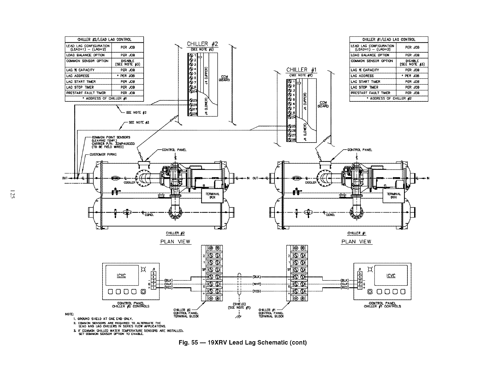
(}.fILLER #T21LEAD LA¢ CONTROL
LEAD LAG CONFIGURATION
(LEAD=l) -- (LAG=2] PER JOB
LOAD S_LANCE OPTION PER JOB
C(_AMON SE]qSOR OPTION DISABLE
[SEE NOTE _,)
LAG _. C_PAOTY pER JOB
LAG ADDRESS * PER dOS
LAG START TIMER P_ ,JOB
LAG STOP "nMER PER JOB
PRESTART FAULT "IJ3M_ P{_:_ JOB
• ADDRESS OF" CHILLER #t
PANEL
CHILLER #2
(sE_NO_ #2)
_s
BECM
_2e
CHILLER #I
_q
LJ_
PLAN VIEW
I00 {'/.}11
I(_) (=)1 I
I0=0 (_.}11
Fig. 55 -- 19XRV Lead Lag Schematic (cont)
PLAN VIEW
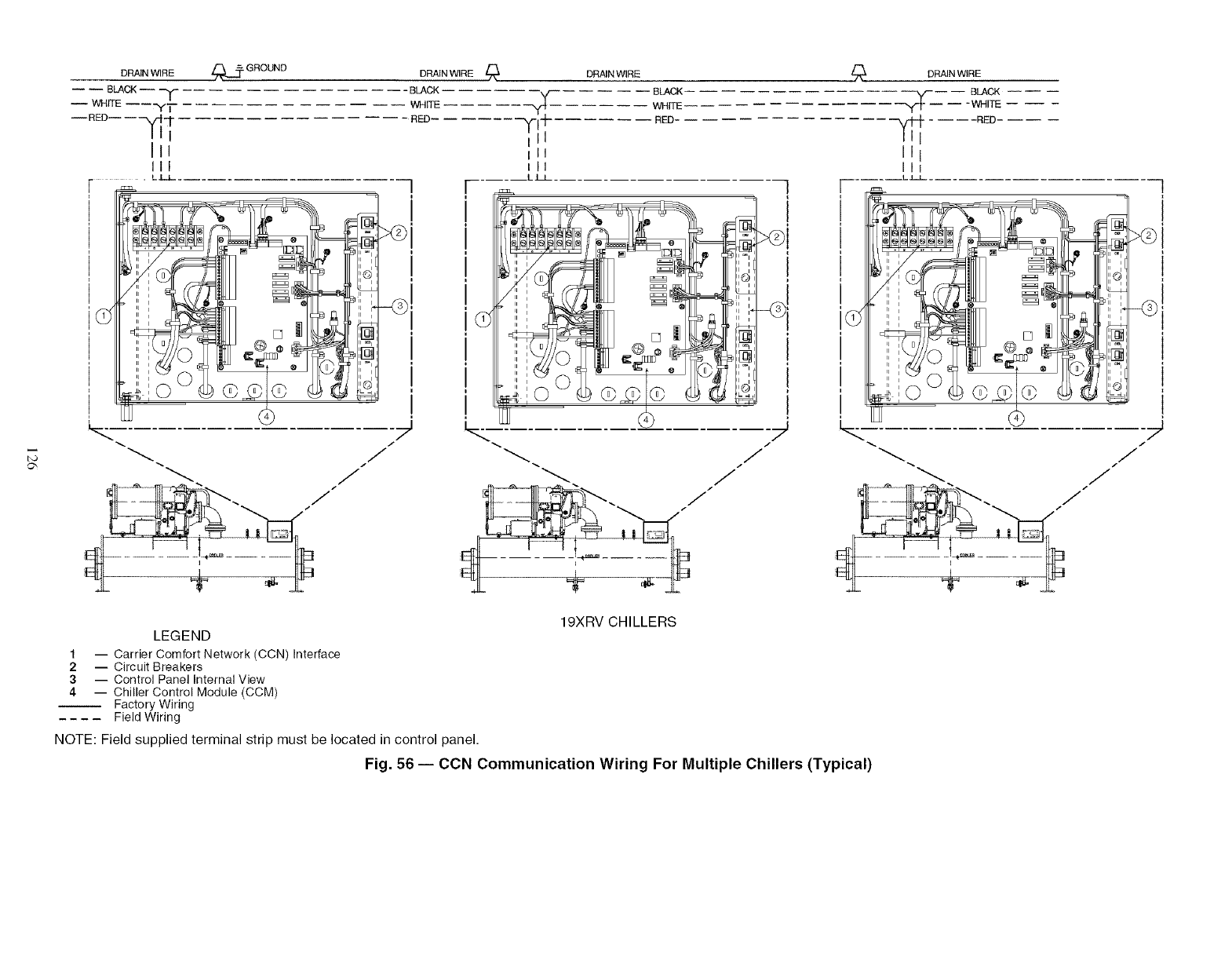
_._ GROUND DRAIN WIRE
DRAIN WIRE
BLACK --
-- WHITE ----'Y/
--RED-- -- --V-I-I---
IIi
II_
III
DRAIN WIRE
-- - BLACK
WHITE -- -- --
- RED ._ BLACK
WHITE
"_- RED-
ill
ill
Ill
+
LJ.J
i i
ui
II
' 1
ui
II i
ni
ui
II i
II i
ni
ui
II i
ni
ui
ui
?
]!
!
-@
J
/
.J
J
DRAIN WIRE
---- BLACK
__ i -WHI_ -- -- --
.... RED
II I
Ill
.LLI
i i
i i
,©
i i
i i
i¢
i i
:@
:@
i i
i i
,©
19XRV CHILLERS
LEGEND
1 -- Carrier Comfort Network (CCN) Interface
2 -- Circuit Breakers
3 -- Control Panel Internal View
4-- Chiller Control Module (CCM)
Factory Wiring
Field Wiring
NOTE: Field supplied terminal strip must be located in control panel.
Fig. 56 -- CCN Communication Wiring For Multiple Chillers (Typical)
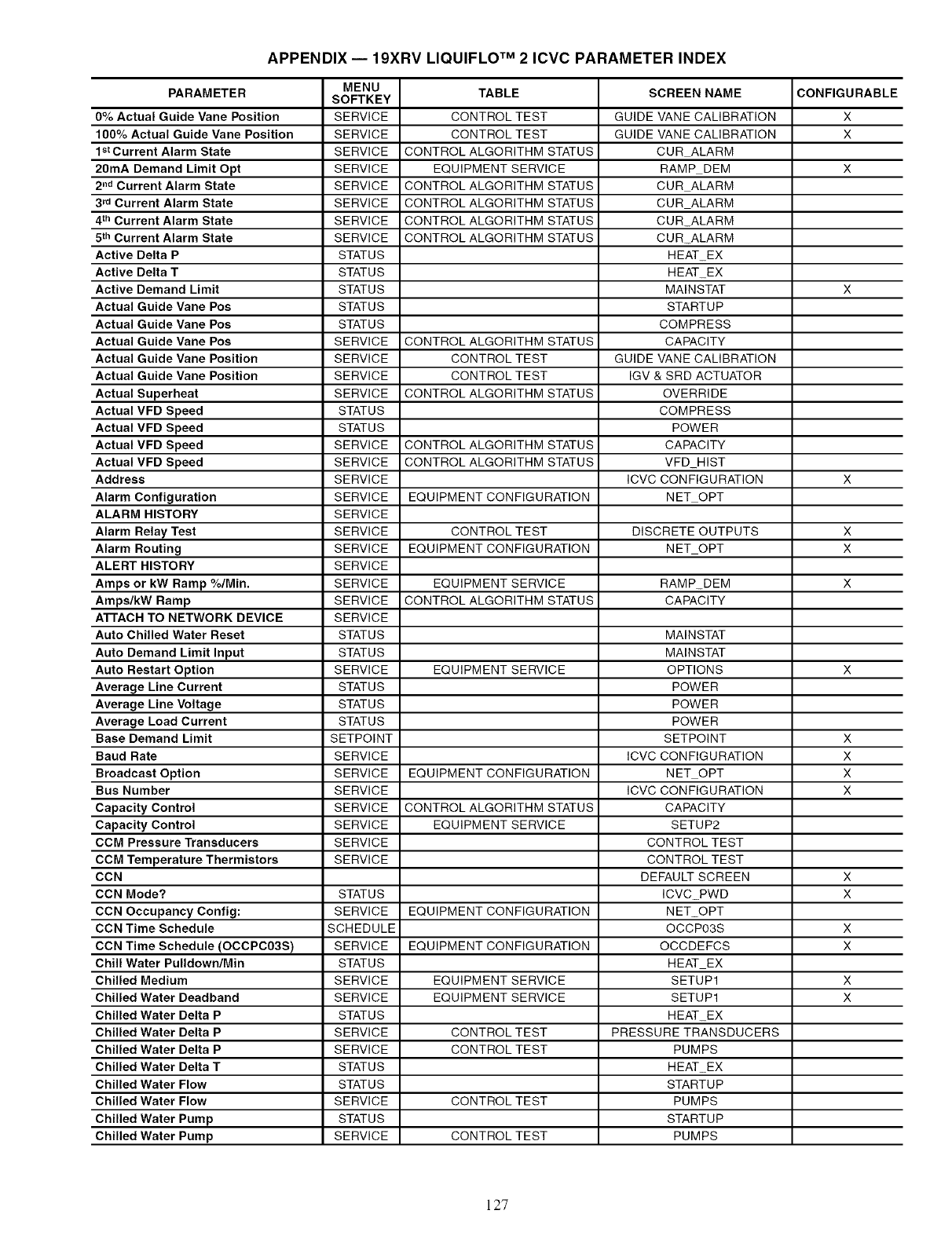
APPENDIX-- 19XRV LIQUIFLO TM 2 ICVC PARAMETER INDEX
MENU TABLE SCREEN NAME CONFIGURABLE
PARAMETER SOFTKEY
0% Actual Guide Vane Position SERVICE CONTROL TEST GUIDE VANE CALIBRATION X
100% Actual Guide Vane Position SERVICE CONTROL TEST GUIDE VANE CALIBRATION X
1stcurrent Alarm State SERVICE CONTROL ALGORITHM STATUS CUR ALARM
20mA Demand Limit Opt SERVICE EQUIPMENT SERVICE RAMP DEM X
2 nd Current Alarm State SERVICE CONTROL ALGORITHM STATUS CUR ALARM
3 rd Current Alarm State SERVICE CONTROL ALGORITHM STATUS CUR ALARM
4 th Current Alarm State SERVICE CONTROL ALGORITHM STATUS CURALARM
5thCurrent Alarm State SERVICE CONTROL ALGORITHM STATUS CURALARM
Active Delta P STATUS HEAT EX
Active Delta T STATUS HEAT EX
Active Demand Limit STATUS MAINSTAT X
Actual Guide Vane Pos STATUS STARTUP
Actual Guide Vane Pos STATUS COMPRESS
Actual Guide Vane Pos SERVICE CONTROL ALGORITHM STATUS CAPACITY
Actual Guide Vane Position SERVICE CONTROL TEST GUIDE VANE CALIBRATION
Actual Guide Vane Position SERVICE CONTROL TEST IGV & SRD ACTUATOR
Actual Superheat SERVICE CONTROL ALGORITHM STATUS OVERRIDE
Actual VFD Speed STATUS COMPRESS
Actual VFD Speed STATUS POWER
Actual VFD Speed SERVICE CONTROL ALGORITHM STATUS CAPACITY
Actual VFD Speed SERVICE CONTROL ALGORITHM STATUS VFD HIST
Address SERVICE ICVC CONFIGURATION X
Alarm Configuration SERVICE EQUIPMENT CONFIGURATION NET OPT
ALARM HISTORY SERVICE
Alarm Relay Test SERVICE CONTROL TEST DISCRETE OUTPUTS X
Alarm Routing SERVICE EQUIPMENT CONFIGURATION NET OPT X
ALERT HISTORY SERVICE
Amps or kW Ramp %/Min. SERVICE EQUIPMENT SERVICE RAMP DEM X
Amps/kW Ramp SERVICE CONTROL ALGORITHM STATUS CAPACITY
ATTACH TO NETWORK DEVICE SERVICE
Auto Chilled Water Reset STATUS MAINSTAT
Auto Demand Limit Input STATUS MAINSTAT
Auto Restart Option SERVICE EQUIPMENT SERVICE OPTIONS X
Average Line Current STATUS POWER
Average Line Voltage STATUS POWER
Average Load Current STATUS POWER
Base Demand Limit SETPOINT SETPOINT X
Baud Rate SERVICE ICVC CONFIGURATION X
Broadcast Option SERVICE EQUIPMENT CONFIGURATION NET OPT X
Bus Number SERVICE ICVC CONFIGURATION X
Capacity Control SERVICE CONTROL ALGORITHM STATUS CAPACITY
Capacity Control SERVICE EQUIPMENT SERVICE SETUP2
CCM Pressure Transducers SERVICE CONTROL TEST
CCM Temperature Thermistors SERVICE CONTROL TEST
CCN DEFAULT SCREEN X
CCN Mode? STATUS ICVC PWD X
CCN Occupancy Config: SERVICE EQUIPMENT CONFIGURATION NET OPT
CCN Time Schedule SCHEDULE OCCP03S X
CCN Time Schedule (OCCPC03S) SERVICE EQUIPMENT CONFIGURATION OCCDEFCS X
Chill Water Pulldown/Min STATUS HEAT EX
Chilled Medium SERVICE EQUIPMENT SERVICE SETUP1 X
Chilled Water Deadband SERVICE EQUIPMENT SERVICE SETUP1 X
Chilled Water Delta P STATUS HEAT EX
Chilled Water Delta P SERVICE CONTROL TEST PRESSURE TRANSDUCERS
Chilled Water Delta P SERVICE CONTROL TEST PUMPS
Chilled Water Delta T STATUS HEAT EX
Chilled Water Flow STATUS STARTUP
Chilled Water Flow SERVICE CONTROL TEST PUMPS
Chilled Water Pump STATUS STARTUP
Chilled Water Pump SERVICE CONTROL TEST PUMPS
127
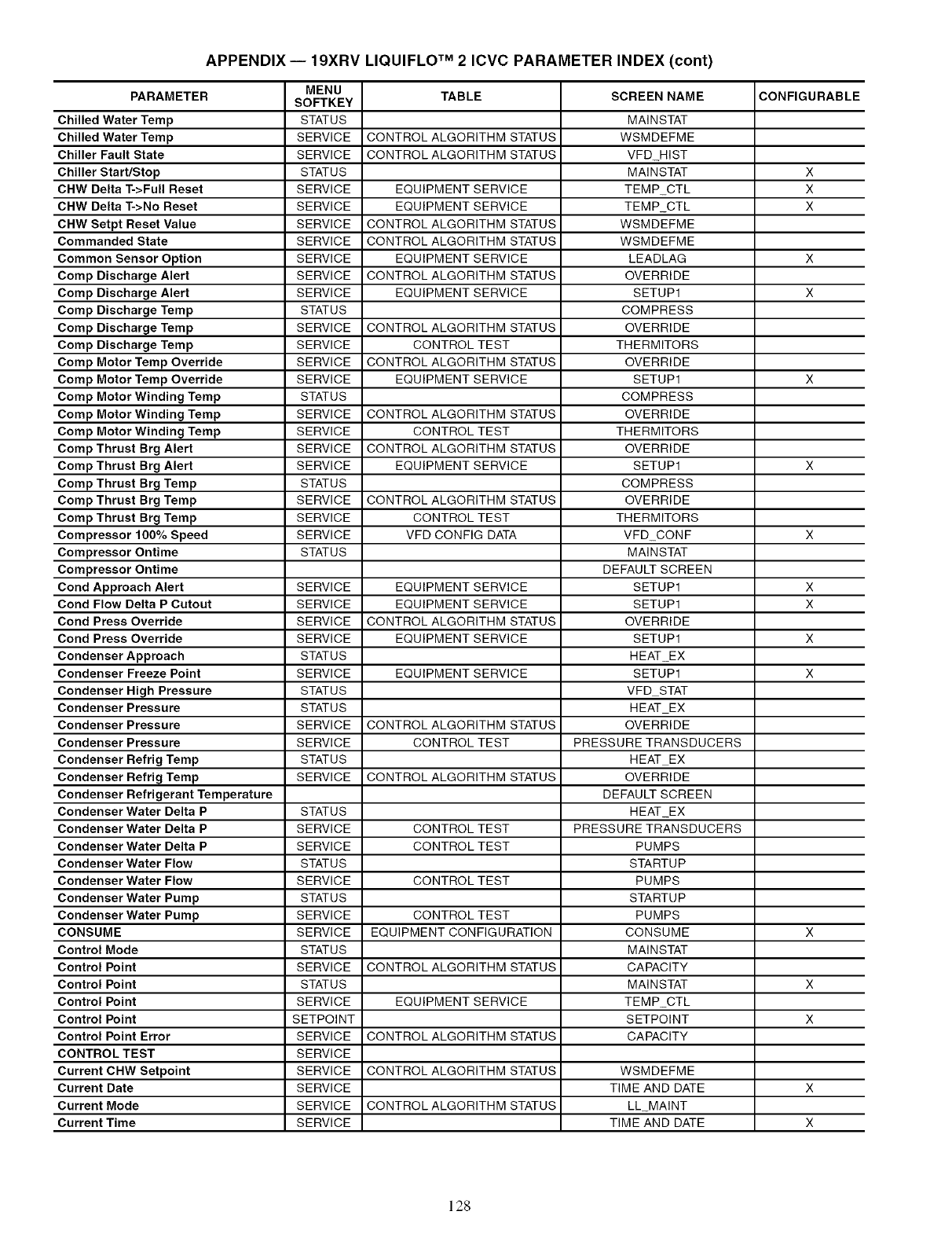
APPENDIX -- 19XRV LIQUlFLO TM 2 ICVC PARAMETER INDEX (cont)
MENU TABLE SCREEN NAME CONFIGURABLE
PARAMETER SOFTKEY
Chilled Water Temp STATUS MAINSTAT
Chilled Water Temp SERVICE CONTROL ALGORITHM STATUS WSMDEFME
Chiller Fault State SERVICE CONTROL ALGORITHM STATUS VFD HIST
Chiller Start/Stop STATUS MAINSTAT X
CHW Delta T->Full Reset SERVICE EQUIPMENT SERVICE TEMP CTL X
CHW Delta T->No Reset SERVICE EQUIPMENT SERVICE TEMP CTL X
CHW Setpt Reset Value SERVICE CONTROL ALGORITHM STATUS WSMDEFME
Commanded State SERVICE CONTROL ALGORITHM STATUS WSMDEFME
Common Sensor Option SERVICE EQUIPMENT SERVICE LEADLAG X
Comp Discharge Alert SERVICE CONTROL ALGORITHM STATUS OVERRIDE
Comp Discharge Alert SERVICE EQUIPMENT SERVICE SETUP1 X
Comp Discharge Temp STATUS COMPRESS
Comp Discharge Temp SERVICE CONTROL ALGORITHM STATUS OVERRIDE
Comp Discharge Temp SERVICE CONTROL TEST THERMITORS
Comp Motor Temp Override SERVICE CONTROL ALGORITHM STATUS OVERRIDE
Comp Motor Temp Override SERVICE EQUIPMENT SERVICE SETUP1 X
Comp Motor Winding Temp STATUS COMPRESS
Comp Motor Winding Temp SERVICE CONTROL ALGORITHM STATUS OVERRIDE
Comp Motor Winding Temp SERVICE CONTROL TEST THERMITORS
Comp Thrust Brg Alert SERVICE CONTROL ALGORITHM STATUS OVERRIDE
Comp Thrust Brg Alert SERVICE EQUIPMENT SERVICE SETUP1 X
Comp Thrust Brg Temp STATUS COMPRESS
Comp Thrust Brg Temp SERVICE CONTROL ALGORITHM STATUS OVERRIDE
Comp Thrust Brg Temp SERVICE CONTROL TEST THERMITORS
Compressor 100% Speed SERVICE VFD CONFIG DATA VFD CONF X
Compressor Ontime STATUS MAINSTAT
Compressor Ontime DEFAULT SCREEN
Cond Approach Alert SERVICE EQUIPMENT SERVICE SETUP1 X
Cond Flow Delta P Cutout SERVICE EQUIPMENT SERVICE SETUP1 X
Cond Press Override SERVICE CONTROL ALGORITHM STATUS OVERRIDE
Cond Press Override SERVICE EQUIPMENT SERVICE SETUP1 X
Condenser Approach STATUS HEAT EX
Condenser Freeze Point SERVICE EQUIPMENT SERVICE SETUP1 X
Condenser High Pressure STATUS VFD STAT
Condenser Pressure STATUS HEAT EX
Condenser Pressure SERVICE CONTROL ALGORITHM STATUS OVERRIDE
Condenser Pressure SERVICE CONTROL TEST PRESSURE TRANSDUCERS
Condenser Refrig Temp STATUS HEAT EX
Condenser Refrig Temp SERVICE CONTROL ALGORITHM STATUS OVERRIDE
Condenser Refrigerant Temperature DEFAULT SCREEN
Condenser Water Delta P STATUS HEAT EX
Condenser Water Delta P SERVICE CONTROL TEST PRESSURE TRANSDUCERS
Condenser Water Delta P SERVICE CONTROL TEST PUMPS
Condenser Water Flow STATUS STARTUP
Condenser Water Flow SERVICE CONTROL TEST PUMPS
Condenser Water Pump STATUS STARTUP
Condenser Water Pump SERVICE CONTROL TEST PUMPS
CONSUME SERVICE EQUIPMENT CONFIGURATION CONSUME X
Control Mode STATUS MAINSTAT
Control Point SERVICE CONTROL ALGORITHM STATUS CAPACITY
Control Point STATUS MAINSTAT X
Control Point SERVICE EQUIPMENT SERVICE TEMP CTL
Control Point SETPOINT SETPOINT X
Control Point Error SERVICE CONTROL ALGORITHM STATUS CAPACITY
CONTROL TEST SERVICE
Current CHW Setpoint SERVICE CONTROL ALGORITHM STATUS WSMDEFME
Current Date SERVICE TIME AND DATE X
Current Mode SERVICE CONTROL ALGORITHM STATUS LL MAINT
Current Time SERVICE TIME AND DATE X
128
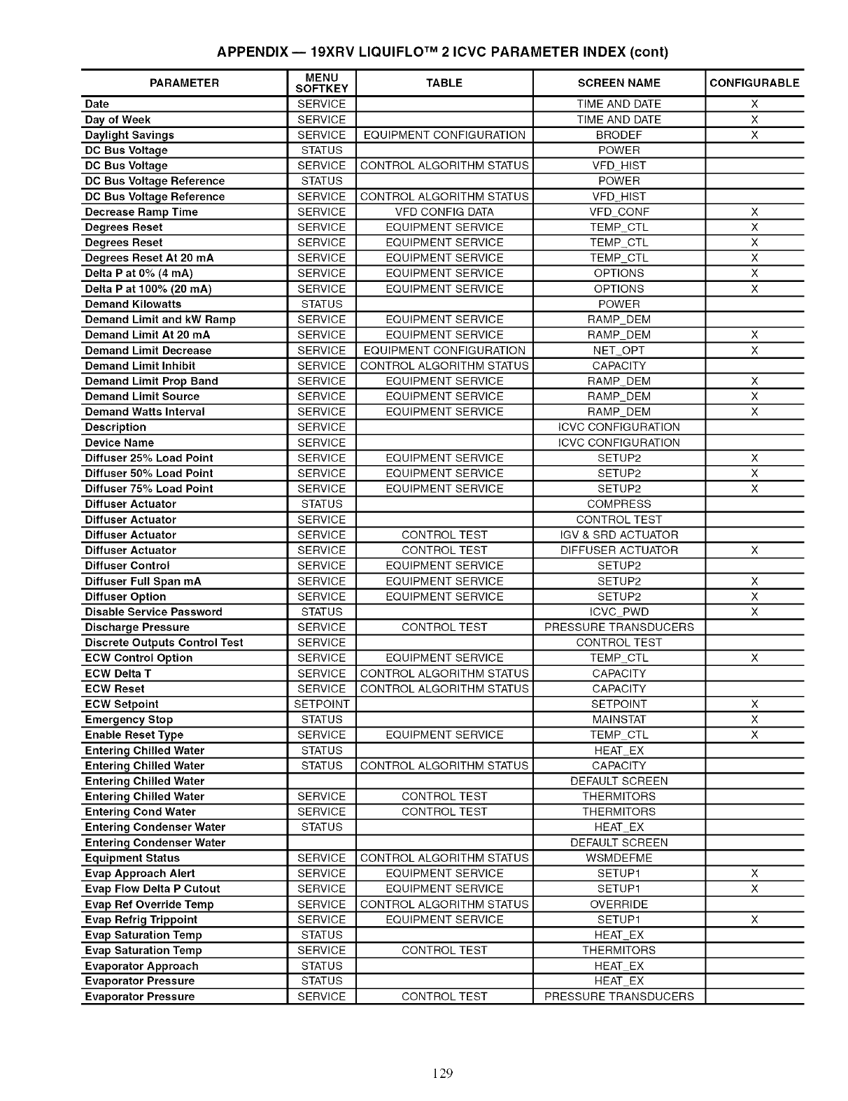
APPENDIX -- 19XRV LIQUlFLO TM 2 ICVC PARAMETER INDEX (cont)
MENU TABLE SCREEN NAME CONFIGURABLE
PARAMETER SOFTKEY
Date SERVICE TIME AND DATE X
Day of Week SERVICE TIME AND DATE X
Daylight Savings SERVICE EQUIPMENT CONFIGURATION BRODEF X
DC Bus Voltage STATUS POWER
DC Bus Voltage SERVICE CONTROL ALGORITHM STATUS VFD HIST
DC Bus Voltage Reference STATUS POWER
DC Bus Voltage Reference SERVICE CONTROL ALGORITHM STATUS VFD HIST
Decrease Ramp Time SERVICE VFD CONFIG DATA VFD CONF X
Degrees Reset SERVICE EQUIPMENT SERVICE TEMP CTL X
Degrees Reset SERVICE EQUIPMENT SERVICE TEMP CTL X
Degrees Reset At 20 mA SERVICE EQUIPMENT SERVICE TEMP CTL X
Delta P at 0% (4 mA) SERVICE EQUIPMENT SERVICE OPTIONS X
Delta P at 100% (20 mA) SERVICE EQUIPMENT SERVICE OPTIONS X
Demand Kilowatts STATUS POWER
Demand Limit and kW Ramp SERVICE EQUIPMENT SERVICE RAMP DEM
Demand Limit At 20 mA SERVICE EQUIPMENT SERVICE RAMP DEM X
Demand Limit Decrease SERVICE EQUIPMENT CONFIGURATION NET OPT X
Demand Limit Inhibit SERVICE CONTROL ALGORITHM STATUS CAPACITY
Demand Limit Prop Band SERVICE EQUIPMENT SERVICE RAMP DEM X
Demand Limit Source SERVICE EQUIPMENT SERVICE RAMP DEM X
Demand Watts Interval SERVICE EQUIPMENT SERVICE RAMP DEM X
Description SERVICE ICVC CONFIGURATION
Device Name SERVICE ICVC CONFIGURATION
Diffuser 25% Load Point SERVICE EQUIPMENT SERVICE SETUP2 X
Diffuser 50% Load Point SERVICE EQUIPMENT SERVICE SETUP2 X
Diffuser 75% Load Point SERVICE EQUIPMENT SERVICE SETUP2 X
Diffuser Actuator STATUS COMPRESS
Diffuser Actuator SERVICE CONTROL TEST
Diffuser Actuator SERVICE CONTROL TEST IGV & SRD ACTUATOR
Diffuser Actuator SERVICE CONTROL TEST DIFFUSER ACTUATOR X
Diffuser Control SERVICE EQUIPMENT SERVICE SETUP2
Diffuser Full Span mA SERVICE EQUIPMENT SERVICE SETUP2 X
Diffuser Option SERVICE EQUIPMENT SERVICE SETUP2 X
Disable Service Password STATUS ICVC PWD X
Discharge Pressure SERVICE CONTROL TEST PRESSURE TRANSDUCERS
Discrete Outputs Control Test SERVICE CONTROL TEST
ECW Control Option SERVICE EQUIPMENT SERVICE TEMP CTL X
ECW Delta T SERVICE CONTROL ALGORITHM STATUS CAPACITY
ECW Reset SERVICE CONTROL ALGORITHM STATUS CAPACITY
ECW Setpoint SETPOINT SETPOINT X
Emergency Stop STATUS MAINSTAT X
Enable Reset Type SERVICE EQUIPMENT SERVICE TEMP CTL X
Entering Chilled Water STATUS HEAT EX
Entering Chilled Water STATUS CONTROL ALGORITHM STATUS CAPACITY
Entering Chilled Water DEFAULT SCREEN
Entering Chilled Water SERVICE CONTROL TEST THERMITORS
Entering Cond Water SERVICE CONTROL TEST THERMITORS
Entering Condenser Water STATUS HEAT EX
Entering Condenser Water DEFAULT SCREEN
Equipment Status SERVICE CONTROL ALGORITHM STATUS WSMDEFME
Evap Approach Alert SERVICE EQUIPMENT SERVICE SETUP1 X
Evap Flow Delta P Cutout SERVICE EQUIPMENT SERVICE SETUP1 X
Evap Ref Override Temp SERVICE CONTROL ALGORITHM STATUS OVERRIDE
Evap Refrig Trippoint SERVICE EQUIPMENT SERVICE SETUP1 X
Evap Saturation Temp STATUS HEAT EX
Evap Saturation Temp SERVICE CONTROL TEST THERMITORS
Evaporator Approach STATUS HEAT EX
Evaporator Pressure STATUS HEAT EX
Evaporator Pressure SERVICE CONTROL TEST PRESSURE TRANSDUCERS
129
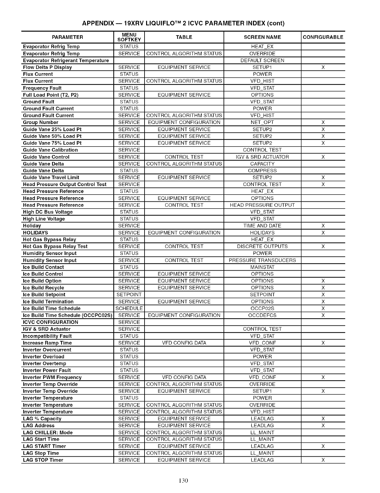
APPENDIX -- 19XRV LIQUlFLO TM 2 ICVC PARAMETER INDEX (cont)
MENU TABLE SCREEN NAME CONFIGURABLE
PARAMETER SOFTKEY
Evaporator Refrig Temp STATUS HEAT EX
Evaporator Refrig Temp SERVICE CONTROL ALGORITHM STATUS OVERRIDE
Evaporator Refrigerant Temperature DEFAULT SCREEN
Flow Delta P Display SERVICE EQUIPMENT SERVICE SETUP1 X
Flux Current STATUS POWER
Flux Current SERVICE CONTROL ALGORITHM STATUS VFD HIST
Frequency Fault STATUS VFD STAT
Full Load Point (T2, P2) SERVICE EQUIPMENT SERVICE OPTIONS
Ground Fault STATUS VFD STAT
Ground Fault Current STATUS POWER
Ground Fault Current SERVICE CONTROL ALGORITHM STATUS VFD HIST
Group Number SERVICE EQUIPMENT CONFIGURATION NET OPT X
Guide Vane 25% Load Pt SERVICE EQUIPMENT SERVICE SETUP2 X
Guide Vane 50% Load Pt SERVICE EQUIPMENT SERVICE SETUP2 X
Guide Vane 75% Load Pt SERVICE EQUIPMENT SERVICE SETUP2 X
Guide Vane Calibration SERVICE CONTROL TEST
Guide Vane Control SERVICE CONTROL TEST IGV & SRD ACTUATOR X
Guide Vane Delta SERVICE CONTROL ALGORITHM STATUS CAPACITY
Guide Vane Delta STATUS COMPRESS
Guide Vane Travel Limit SERVICE EQUIPMENT SERVICE SETUP2 X
Head Pressure Output Control Test SERVICE CONTROL TEST X
Head Pressure Reference STATUS HEAT EX
Head Pressure Reference SERVICE EQUIPMENT SERVICE OPTIONS
Head Pressure Reference SERVICE CONTROL TEST HEAD PRESSURE OUTPUT
High DC Bus Voltage STATUS VFD STAT
High Line Voltage STATUS VFD STAT
Holiday SERVICE TIME AND DATE X
HOLIDAYS SERVICE EQUIPMENT CONFIGURATION HOLIDAYS X
Hot Gas Bypass Relay STATUS HEAT EX
Hot Gas Bypass Relay Test SERVICE CONTROL TEST DISCRETE OUTPUTS X
Humidity Sensor Input STATUS POWER
Humidity Sensor Input SERVICE CONTROL TEST PRESSURE TRANSDUCERS
Ice Build Contact STATUS MAINSTAT
Ice Build Control SERVICE EQUIPMENT SERVICE OPTIONS
Ice Build Option SERVICE EQUIPMENT SERVICE OPTIONS X
Ice Build Recycle SERVICE EQUIPMENT SERVICE OPTIONS X
Ice Build Setpoint SETPOINT SETPOINT X
Ice Build Termination SERVICE EQUIPMENT SERVICE OPTIONS X
Ice Build Time Schedule SCHEDULE OCCP02S X
Ice Build Time Schedule (OCCPC02S) SERVICE EQUIPMENT CONFIGURATION OCCDEFCS X
ICVC CONFIGURATION SERVICE
IGV & SRD Actuator SERVICE CONTROL TEST
Incompatibility Fault STATUS VFD STAT
Increase Ramp Time SERVICE VFD CONFIG DATA VFD CONF X
Inverter Overcurrent STATUS VFD STAT
Inverter Overload STATUS POWER
Inverter Overtemp STATUS VFD STAT
Inverter Power Fault STATUS VFD STAT
Inverter PWM Frequency SERVICE VFD CONFIG DATA VFD CONF X
Inverter Temp Override SERVICE CONTROL ALGORITHM STATUS OVERRIDE
Inverter Temp Override SERVICE EQUIPMENT SERVICE SETUP1 X
Inverter Temperature STATUS POWER
Inverter Temperature SERVICE CONTROL ALGORITHM STATUS OVERRIDE
Inverter Temperature SERVICE CONTROL ALGORITHM STATUS VFD HIST
LAG % Capacity SERVICE EQUIPMENT SERVICE LEADLAG X
LAG Address SERVICE EQUIPMENT SERVICE LEADLAG X
LAG CHILLER: Mode SERVICE CONTROL ALGORITHM STATUS LL MAINT
LAG Start Time SERVICE CONTROL ALGORITHM STATUS LL MAINT
LAG START Timer SERVICE EQUIPMENT SERVICE LEADLAG X
LAG Stop Time SERVICE CONTROL ALGORITHM STATUS LL MAINT
LAG STOP Timer SERVICE EQUIPMENT SERVICE LEADLAG X
130
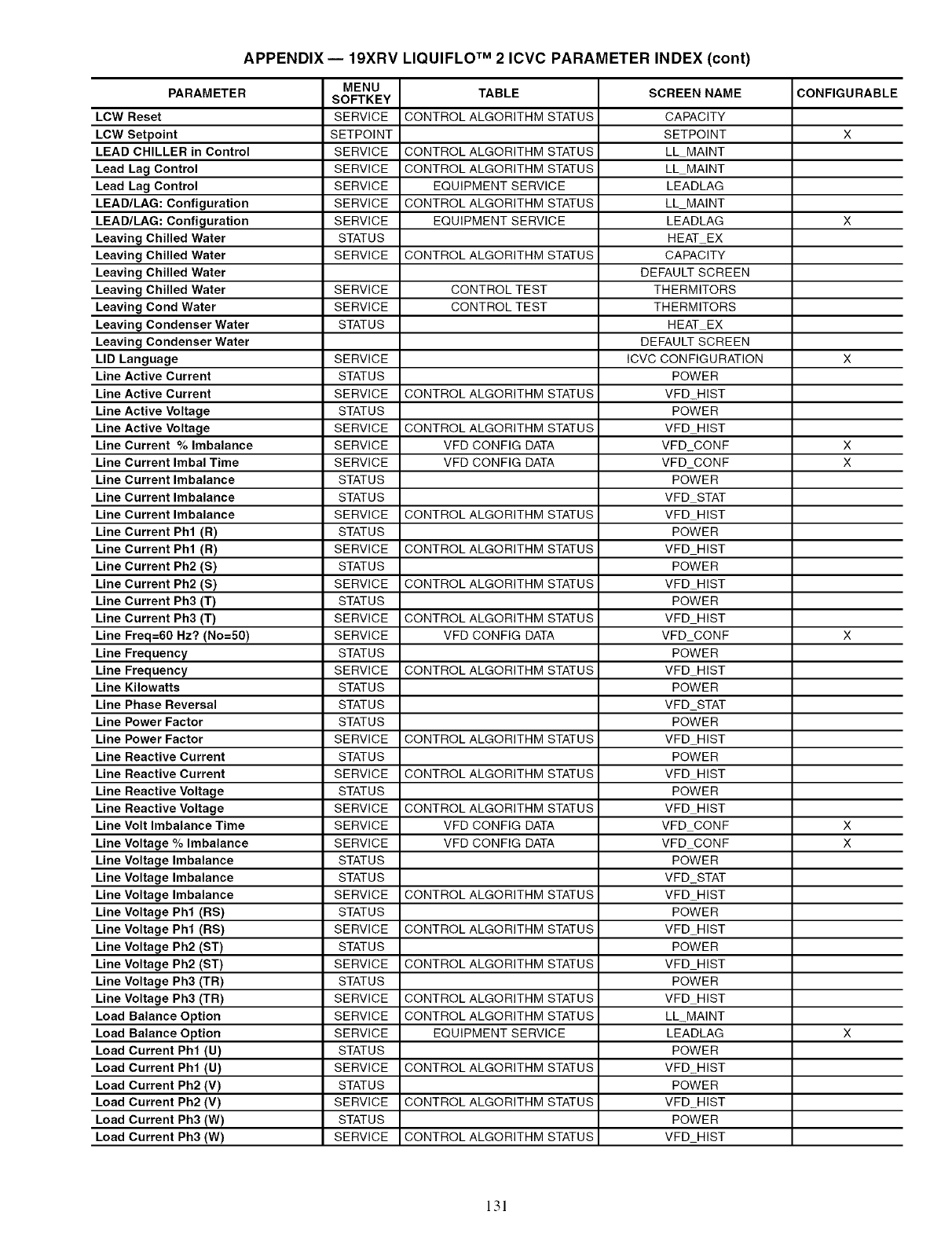
APPENDIX -- 19XRV LIQUlFLO TM 2 ICVC PARAMETER INDEX (cont)
MENU TABLE SCREEN NAME CONFIGURABLE
PARAMETER SOFTKEY
LCW Reset SERVICE CONTROL ALGORITHM STATUS CAPACITY
LCW Setpoint SETPOINT SETPOINT X
LEAD CHILLER in Control SERVICE CONTROL ALGORITHM STATUS LLMAINT
Lead Lag Control SERVICE CONTROL ALGORITHM STATUS LLMAINT
Lead Lag Control SERVICE EQUIPMENT SERVICE LEADLAG
LEAD/LAG: Configuration SERVICE CONTROL ALGORITHM STATUS LLMAINT
LEAD/LAG: Configuration SERVICE EQUIPMENT SERVICE LEADLAG X
Leaving Chilled Water STATUS HEAT EX
Leaving Chilled Water SERVICE CONTROL ALGORITHM STATUS CAPACITY
Leaving Chilled Water DEFAULT SCREEN
Leaving Chilled Water SERVICE CONTROL TEST THERMITORS
Leaving Cond Water SERVICE CONTROL TEST THERMITORS
Leaving Condenser Water STATUS HEAT EX
Leaving Condenser Water DEFAULT SCREEN
LID Language SERVICE ICVC CONFIGURATION X
Line Active Current STATUS POWER
Line Active Current SERVICE CONTROL ALGORITHM STATUS VFD HIST
Line Active Voltage STATUS POWER
Line Active Voltage SERVICE CONTROL ALGORITHM STATUS VFD HIST
Line Current % Imbalance SERVICE VFD CONFIG DATA VFD CONF X
Line Current Imbal Time SERVICE VFD CONFIG DATA VFD CONF X
Line Current Imbalance STATUS POWER
Line Current Imbalance STATUS VFD STAT
Line Current Imbalance SERVICE CONTROL ALGORITHM STATUS VFD HIST
Line Current Phl (R) STATUS POWER
Line Current Phl (R) SERVICE CONTROL ALGORITHM STATUS VFD HIST
Line Current Ph2 (S) STATUS POWER
Line Current Ph2 (S) SERVICE CONTROL ALGORITHM STATUS VFD HIST
Line Current Ph3 (T) STATUS POWER
Line Current Ph3 (T) SERVICE CONTROL ALGORITHM STATUS VFD HIST
Line Freq=60 Hz? (No=50) SERVICE VFD CONFIG DATA VFD CONF X
Line Frequency STATUS POWER
Line Frequency SERVICE CONTROL ALGORITHM STATUS VFD HIST
Line Kilowatts STATUS POWER
Line Phase Reversal STATUS VFD STAT
Line Power Factor STATUS POWER
Line Power Factor SERVICE CONTROL ALGORITHM STATUS VFD HIST
Line Reactive Current STATUS POWER
Line Reactive Current SERVICE CONTROL ALGORITHM STATUS VFD HIST
Line Reactive Voltage STATUS POWER
Line Reactive Voltage SERVICE CONTROL ALGORITHM STATUS VFD HIST
Line Volt Imbalance Time SERVICE VFD CONFIG DATA VFD CONF X
Line Voltage % Imbalance SERVICE VFD CONFIG DATA VFD CONF X
Line Voltage Imbalance STATUS POWER
Line Voltage Imbalance STATUS VFD STAT
Line Voltage Imbalance SERVICE CONTROL ALGORITHM STATUS VFD HIST
Line Voltage Phl (RS) STATUS POWER
Line Voltage Phl (RS) SERVICE CONTROL ALGORITHM STATUS VFD HIST
Line Voltage Ph2 (ST) STATUS POWER
Line Voltage Ph2 (ST) SERVICE CONTROL ALGORITHM STATUS VFD HIST
Line Voltage Ph3 (TR) STATUS POWER
Line Voltage Ph3 (TR) SERVICE CONTROL ALGORITHM STATUS VFD HIST
Load Balance Option SERVICE CONTROL ALGORITHM STATUS LL MAINT
Load Balance Option SERVICE EQUIPMENT SERVICE LEADLAG X
Load Current Phl (U) STATUS POWER
Load Current Phl (U) SERVICE CONTROL ALGORITHM STATUS VFD HIST
Load Current Ph2 (V) STATUS POWER
Load Current Ph2 (V) SERVICE CONTROL ALGORITHM STATUS VFD HIST
Load Current Ph3 (W) STATUS POWER
Load Current Ph3 (W) SERVICE CONTROL ALGORITHM STATUS VFD HIST
131
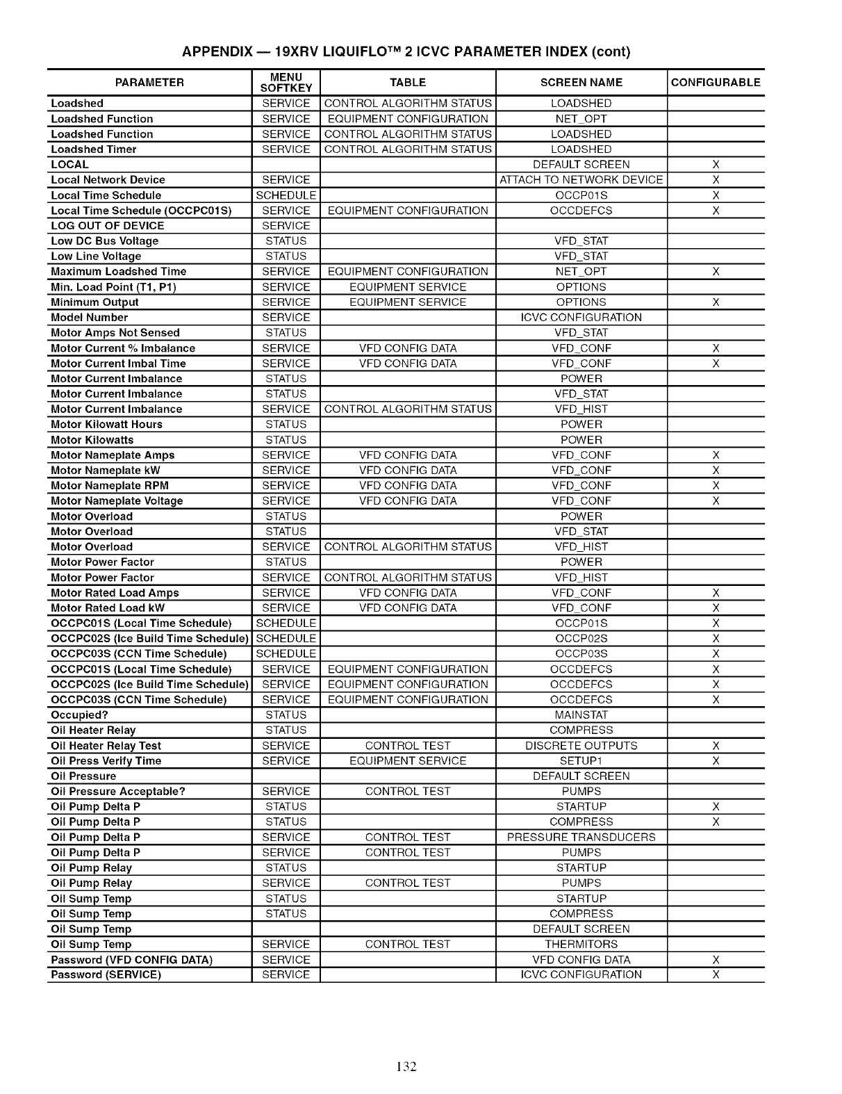
APPENDIX -- 19XRV LIQUlFLO TM 2 ICVC PARAMETER INDEX (cont)
MENU TABLE SCREEN NAME CONFIGURABLE
PARAMETER SOFTKEY
Loadshed SERVICE CONTROL ALGORITHM STATUS LOADSHED
Loadshed Function SERVICE EQUIPMENT CONFIGURATION NET OPT
Loadshed Function SERVICE CONTROL ALGORITHM STATUS LOADSHED
Loadshed Timer SERVICE CONTROL ALGORITHM STATUS LOADSHED
LOCAL DEFAULT SCREEN X
Local Network Device SERVICE ATTACH TO NETWORK DEVICE X
Local Time Schedule SCHEDULE OCCP01S X
Local Time Schedule (OCCPC01 S) SERVICE EQUIPMENT CONFIGURATION OCCDEFCS X
LOG OUT OF DEVICE SERVICE
Low DC Bus Voltage STATUS VFD STAT
Low Line Voltage STATUS VFD STAT
Maximum Loadshed Time SERVICE EQUIPMENT CONFIGURATION NET OPT X
Min. Load Point (T1, P1) SERVICE EQUIPMENT SERVICE OPTIONS
Minimum Output SERVICE EQUIPMENT SERVICE OPTIONS X
Model Number SERVICE ICVC CONFIGURATION
Motor Amps Not Sensed STATUS VFD STAT
Motor Current % Imbalance SERVICE VFD CONFIG DATA VFD CONF X
Motor Current Imbal Time SERVICE VFD CONFIG DATA VFD CONF X
Motor Current Imbalance STATUS POWER
Motor Current Imbalance STATUS VFD STAT
Motor Current Imbalance SERVICE CONTROL ALGORITHM STATUS VFD HIST
Motor Kilowatt Hours STATUS POWER
Motor Kilowatts STATUS POWER
Motor Nameplate Amps SERVICE VFD CONFIG DATA VFD CONF X
Motor Nameplate kW SERVICE VFD CONFIG DATA VFD CONF X
Motor Nameplate RPM SERVICE VFD CONFIG DATA VFD CONF X
Motor Nameplate Voltage SERVICE VFD CONFIG DATA VFD CONF X
Motor Overload STATUS POWER
Motor Overload STATUS VFD STAT
Motor Overload SERVICE CONTROL ALGORITHM STATUS VFD HIST
Motor Power Factor STATUS POWER
Motor Power Factor SERVICE CONTROL ALGORITHM STATUS VFD HIST
Motor Rated Load Amps SERVICE VFD CONFIG DATA VFD CONF X
Motor Rated Load kW SERVICE VFD CONFIG DATA VFD CONF X
OCCPC01S (Local Time Schedule) SCHEDULE OCCP01S X
OCCPC02S (Ice Build Time Schedule) SCHEDULE OCCP02S X
OCCPC03S (CCN Time Schedule) SCHEDULE OCCP03S X
OCCPC01S (Local Time Schedule) SERVICE EQUIPMENT CONFIGURATION OCCDEFCS X
OCCPC02S (Ice Build Time Schedule) SERVICE EQUIPMENT CONFIGURATION OCCDEFCS X
OCCPC03S (CCN Time Schedule) SERVICE EQUIPMENT CONFIGURATION OCCDEFCS X
Occupied? STATUS MAINSTAT
Oil Heater Relay STATUS COMPRESS
Oil Heater Relay Test SERVICE CONTROL TEST DISCRETE OUTPUTS X
Oil Press Verify Time SERVICE EQUIPMENT SERVICE SETUP1 X
Oil Pressure DEFAULT SCREEN
Oil Pressure Acceptable? SERVICE CONTROL TEST PUMPS
Oil Pump Delta P STATUS STARTUP X
Oil Pump Delta P STATUS COMPRESS X
Oil Pump Delta P SERVICE CONTROL TEST PRESSURE TRANSDUCERS
Oil Pump Delta P SERVICE CONTROL TEST PUMPS
Oil Pump Relay STATUS STARTUP
Oil Pump Relay SERVICE CONTROL TEST PUMPS
Oil Sump Temp STATUS STARTUP
Oil Sump Temp STATUS COMPRESS
Oil Sump Temp DEFAULT SCREEN
Oil Sump Temp SERVICE CONTROL TEST THERMITORS
Password (VFD CONFIG DATA) SERVICE VFD CONFIG DATA X
Password (SERVICE) SERVICE ICVC CONFIGURATION X
132
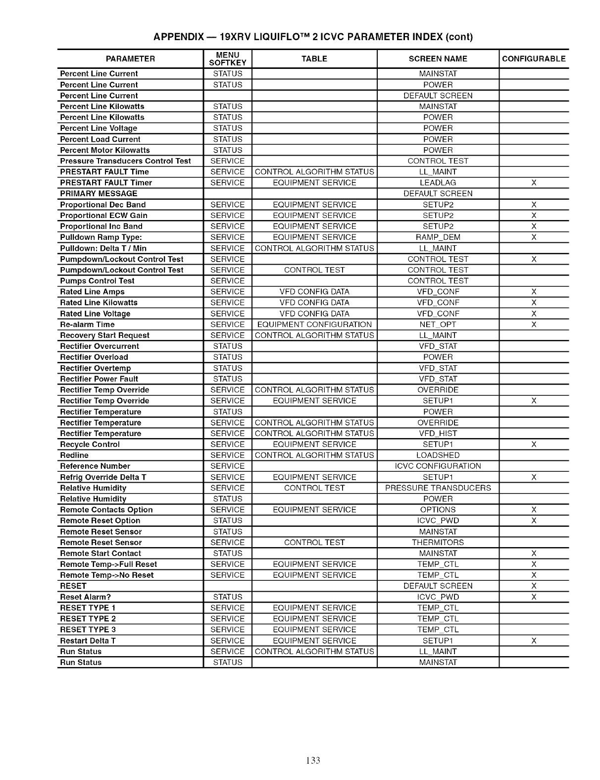
APPENDIX -- 19XRV LIQUlFLO TM 2 ICVC PARAMETER INDEX (cont)
MENU TABLE SCREEN NAME CONFIGURABLE
PARAMETER SOFTKEY
Percent Line Current STATUS MAINSTAT
Percent Line Current STATUS POWER
Percent Line Current DEFAULT SCREEN
Percent Line Kilowatts STATUS MAINSTAT
Percent Line Kilowatts STATUS POWER
Percent Line Voltage STATUS POWER
Percent Load Current STATUS POWER
Percent Motor Kilowatts STATUS POWER
Pressure Transducers Control Test SERVICE CONTROL TEST
PRESTART FAULT Time SERVICE CONTROL ALGORITHM STATUS LL MAINT
PRESTART FAULT Timer SERVICE EQUIPMENT SERVICE LEADLAG X
PRIMARY MESSAGE DEFAULT SCREEN
Proportional Dec Band SERVICE EQUIPMENT SERVICE SETUP2 X
Proportional ECW Gain SERVICE EQUIPMENT SERVICE SETUP2 X
Proportional Inc Band SERVICE EQUIPMENT SERVICE SETUP2 X
Pulldown Ramp Type: SERVICE EQUIPMENT SERVICE RAMP DEM X
Pulldown: Delta T/Min SERVICE CONTROL ALGORITHM STATUS LL MAINT
Pumpdown/Lockout Control Test SERVICE CONTROL TEST X
Pumpdown/Lockout Control Test SERVICE CONTROL TEST CONTROL TEST
Pumps Control Test SERVICE CONTROL TEST
Rated Line Amps SERVICE VFD CONFIG DATA VFD CONF X
Rated Line Kilowatts SERVICE VFD CONFIG DATA VFD CONF X
Rated Line Voltage SERVICE VFD CONFIG DATA VFD CONF X
Re-alarm Time SERVICE EQUIPMENT CONFIGURATION NET OPT X
Recovery Start Request SERVICE CONTROL ALGORITHM STATUS LLMAINT
Rectifier Overcurrent STATUS VFD STAT
Rectifier Overload STATUS POWER
Rectifier Overtemp STATUS VFD STAT
Rectifier Power Fault STATUS VFD STAT
Rectifier Temp Override SERVICE CONTROL ALGORITHM STATUS OVERRIDE
Rectifier Temp Override SERVICE EQUIPMENT SERVICE SETUP1 X
Rectifier Temperature STATUS POWER
Rectifier Temperature SERVICE CONTROL ALGORITHM STATUS OVERRIDE
Rectifier Temperature SERVICE CONTROL ALGORITHM STATUS VFD HIST
Recycle Control SERVICE EQUIPMENT SERVICE SETUP1 X
Redline SERVICE CONTROL ALGORITHM STATUS LOADSHED
Reference Number SERVICE ICVC CONFIGURATION
Refrig Override Delta T SERVICE EQUIPMENT SERVICE SETUP1 X
Relative Humidity SERVICE CONTROL TEST PRESSURE TRANSDUCERS
Relative Humidity STATUS POWER
Remote Contacts Option SERVICE EQUIPMENT SERVICE OPTIONS X
Remote Reset Option STATUS ICVC PWD X
Remote Reset Sensor STATUS MAINSTAT
Remote Reset Sensor SERVICE CONTROL TEST THERMITORS
Remote Start Contact STATUS MAINSTAT X
Remote Temp->Full Reset SERVICE EQUIPMENT SERVICE TEMP CTL X
Remote Temp->No Reset SERVICE EQUIPMENT SERVICE TEMP CTL X
RESET DEFAULT SCREEN X
Reset Alarm? STATUS ICVC PWD X
RESET TYPE 1 SERVICE EQUIPMENT SERVICE TEMP CTL
RESET TYPE 2 SERVICE EQUIPMENT SERVICE TEMP CTL
RESET TYPE 3 SERVICE EQUIPMENT SERVICE TEMP CTL
Restart Delta T SERVICE EQUIPMENT SERVICE SETUP1 X
Run Status SERVICE CONTROL ALGORITHM STATUS LL MAINT
Run Status STATUS MAIN STAT
133
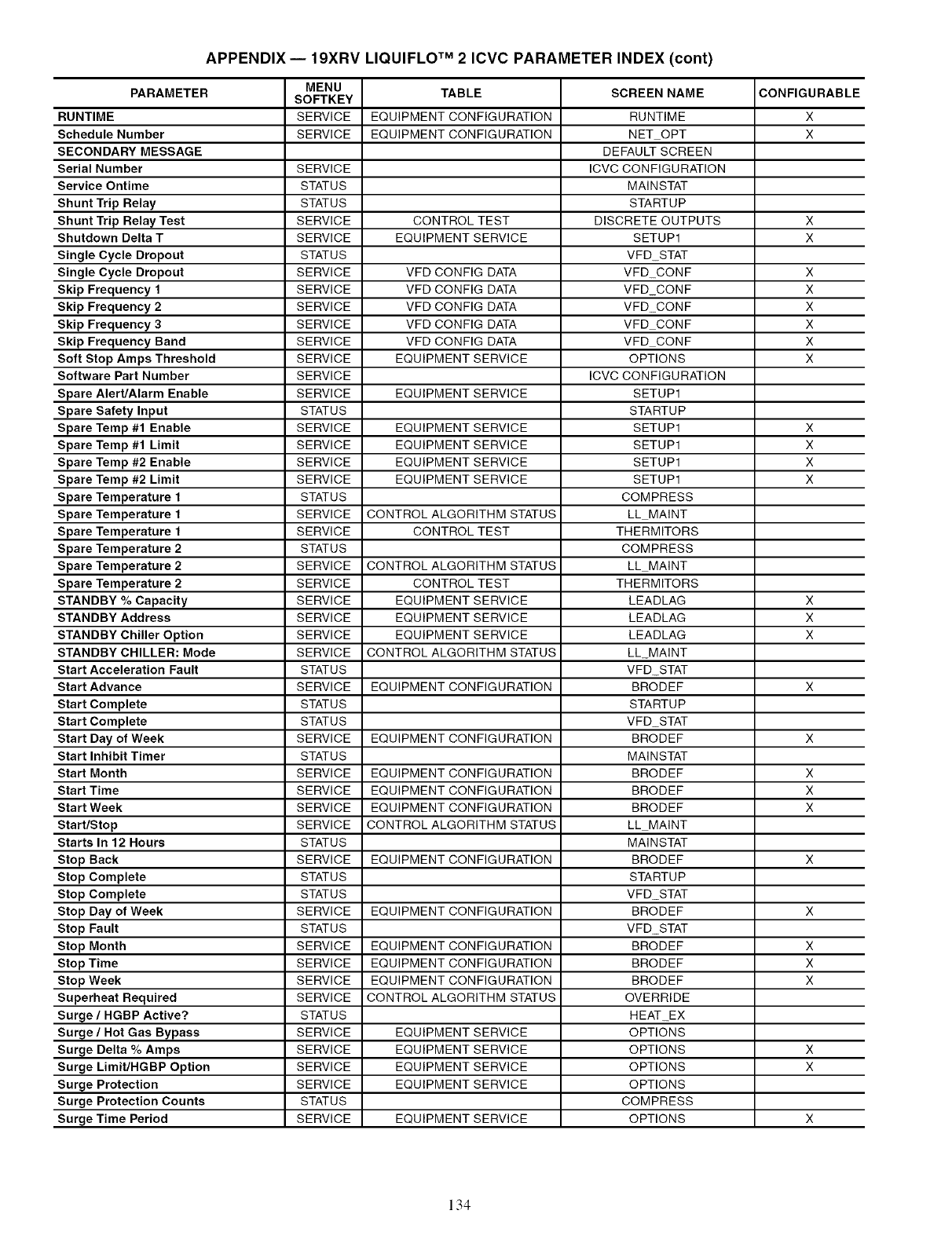
APPENDIX -- 19XRV LIQUlFLO TM 2 ICVC PARAMETER INDEX (cont)
MENU TABLE SCREEN NAME CONFIGURABLE
PARAMETER SOFTKEY
RUNTIME SERVICE EQUIPMENT CONFIGURATION RUNTIME X
Schedule Number SERVICE EQUIPMENT CONFIGURATION NET OPT X
SECONDARY MESSAGE DEFAULT SCREEN
Serial Number SERVICE ICVC CONFIGURATION
Service Ontime STATUS MAINSTAT
Shunt Trip Relay STATUS STARTUP
Shunt Trip Relay Test SERVICE CONTROL TEST DISCRETE OUTPUTS X
Shutdown Delta T SERVICE EQUIPMENT SERVICE SETUP1 X
Single Cycle Dropout STATUS VFD STAT
Single Cycle Dropout SERVICE VFD CONFIG DATA VFD_CONF X
Skip Frequency 1 SERVICE VFD CONFIG DATA VFD CONF X
Skip Frequency 2 SERVICE VFD CONFIG DATA VFD_CONF X
Skip Frequency 3 SERVICE VFD CONFIG DATA VFD CONF X
Skip Frequency Band SERVICE VFD CONFIG DATA VFD CONF X
Soft Stop Amps Threshold SERVICE EQUIPMENT SERVICE OPTIONS X
Software Part Number SERVICE ICVC CONFIGURATION
Spare Alert/Alarm Enable SERVICE EQUIPMENT SERVICE SETUP1
Spare Safety Input STATUS STARTUP
Spare Temp #1 Enable SERVICE EQUIPMENT SERVICE SETUP1 X
Spare Temp #1 Limit SERVICE EQUIPMENT SERVICE SETUP1 X
Spare Temp #2 Enable SERVICE EQUIPMENT SERVICE SETUP1 X
Spare Temp #2 Limit SERVICE EQUIPMENT SERVICE SETUP1 X
Spare Temperature 1 STATUS COMPRESS
Spare Temperature 1 SERVICE CONTROL ALGORITHM STATUS LL MAINT
Spare Temperature 1 SERVICE CONTROL TEST THERMITORS
Spare Temperature 2 STATUS COMPRESS
Spare Temperature 2 SERVICE CONTROL ALGORITHM STATUS LL MAINT
Spare Temperature 2 SERVICE CONTROL TEST THERMITORS
STANDBY % Capacity SERVICE EQUIPMENT SERVICE LEADLAG X
STANDBY Address SERVICE EQUIPMENT SERVICE LEADLAG X
STANDBY Chiller Option SERVICE EQUIPMENT SERVICE LEADLAG X
STANDBY CHILLER: Mode SERVICE CONTROL ALGORITHM STATUS LL_MAINT
Start Acceleration Fault STATUS VFD_STAT
Start Advance SERVICE EQUIPMENT CONFIGURATION BRODEF X
Start Complete STATUS STARTU P
Start Complete STATUS VFD_STAT
Start Day of Week SERVICE EQUIPMENT CONFIGURATION BRODEF X
Start Inhibit Timer STATUS MAINSTAT
Start Month SERVICE EQUIPMENT CONFIGURATION BRODEF X
Start Time SERVICE EQUIPMENT CONFIGURATION BRODEF X
Start Week SERVICE EQUIPMENT CONFIGURATION BRODEF X
Start/Stop SERVICE CONTROL ALGORITHM STATUS LL MAINT
Starts In 12 Hours STATUS MAINSTAT
Stop Back SERVICE EQUIPMENT CONFIGURATION BRODEF X
Stop Complete STATUS STARTU P
Stop Complete STATUS VFD_STAT
Stop Day of Week SERVICE EQUIPMENT CONFIGURATION BRODEF X
Stop Fault STATUS VFD_STAT
Stop Month SERVICE EQUIPMENT CONFIGURATION BRODEF X
Stop Time SERVICE EQUIPMENT CONFIGURATION BRODEF X
Stop Week SERVICE EQUIPMENT CONFIGURATION BRODEF X
Superheat Required SERVICE CONTROL ALGORITHM STATUS OVERRIDE
Surge/HGBP Active? STATUS HEAT_EX
Surge/Hot Gas Bypass SERVICE EQUIPMENT SERVICE OPTIONS
Surge Delta % Amps SERVICE EQUIPMENT SERVICE OPTIONS X
Surge Limit/HGBP Option SERVICE EQUIPMENT SERVICE OPTIONS X
Surge Protection SERVICE EQUIPMENT SERVICE OPTIONS
Surge Protection Counts STATUS COMPRESS
Surge Time Period SERVICE EQUIPMENT SERVICE OPTIONS X
134
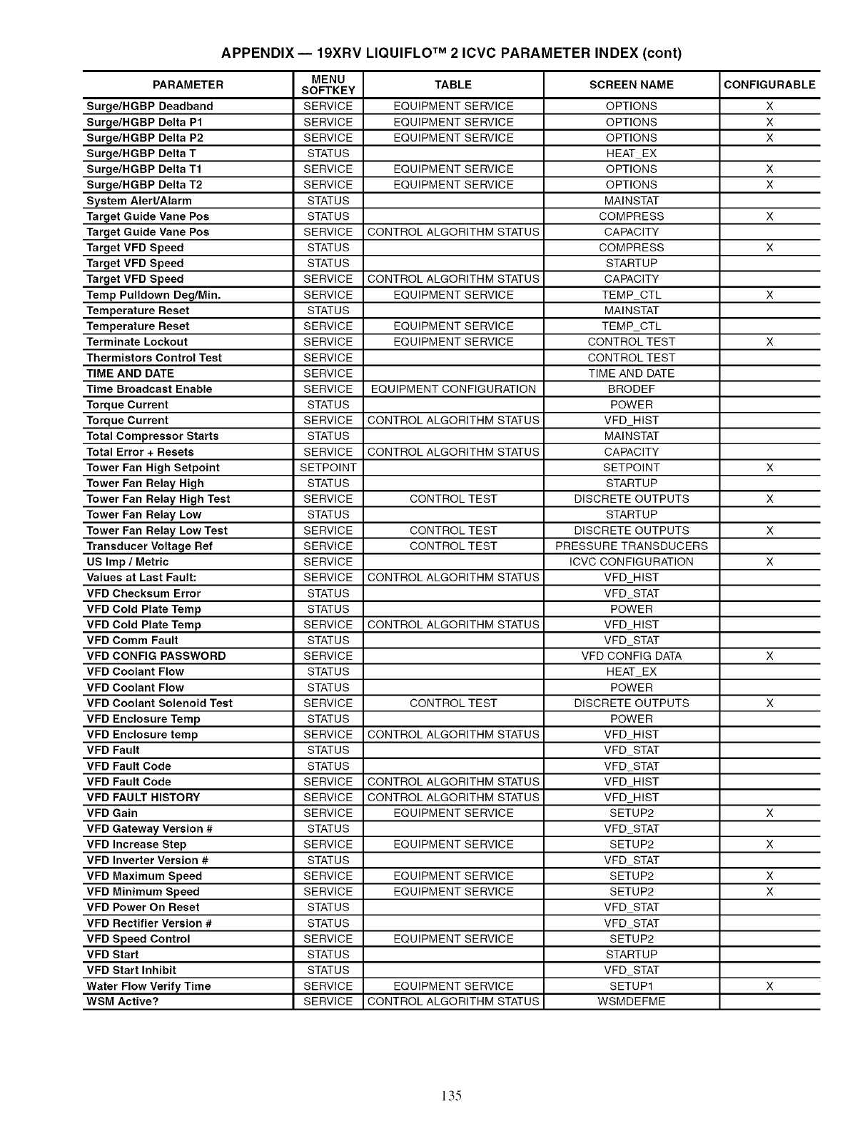
APPENDIX -- 19XRV LIQUlFLO TM 2 ICVC PARAMETER INDEX (cont)
MENU TABLE SCREEN NAME CONFIGURABLE
PARAMETER SOFTKEY
Surge/HGBP Deadband SERVICE EQUIPMENT SERVICE OPTIONS X
Surge/RGBP Delta P1 SERVICE EQUIPMENT SERVICE OPTIONS X
Surge/RGBP Delta P2 SERVICE EQUIPMENT SERVICE OPTIONS X
Surge/RGBP Delta T STATUS HEAT EX
Surge/RGBP Delta T1 SERVICE EQUIPMENT SERVICE OPTIONS X
Surge/RGBP Delta T2 SERVICE EQUIPMENT SERVICE OPTIONS X
System Alert/Alarm STATUS MAINSTAT
Target Guide Vane Pos STATUS COMPRESS X
Target Guide Vane Pos SERVICE CONTROL ALGORITHM STATUS CAPACITY
Target VFD Speed STATUS COMPRESS X
Target VFD Speed STATUS STARTUP
Target VFD Speed SERVICE CONTROL ALGORITHM STATUS CAPACITY
Temp Pulldown Deg/Min. SERVICE EQUIPMENT SERVICE TEMP CTL X
Temperature Reset STATUS MAINSTAT
Temperature Reset SERVICE EQUIPMENT SERVICE TEMP CTL
Terminate Lockout SERVICE EQUIPMENT SERVICE CONTROL TEST X
Thermistors Control Test SERVICE CONTROL TEST
TIME AND DATE SERVICE TIME AND DATE
Time Broadcast Enable SERVICE EQUIPMENT CONFIGURATION BRODEF
Torque Current STATUS POWER
Torque Current SERVICE CONTROL ALGORITHM STATUS VFD HIST
Total Compressor Starts STATUS MAINSTAT
Total Error + Resets SERVICE CONTROL ALGORITHM STATUS CAPACITY
Tower Fan High Setpoint SETPOINT SETPOINT X
Tower Fan Relay High STATUS STARTUP
Tower Fan Relay High Test SERVICE CONTROL TEST DISCRETE OUTPUTS X
Tower Fan Relay Low STATUS STARTUP
Tower Fan Relay Low Test SERVICE CONTROL TEST DISCRETE OUTPUTS X
Transducer Voltage Ref SERVICE CONTROL TEST PRESSURE TRANSDUCERS
US Imp /Metric SERVICE ICVC CONFIGURATION X
Values at Last Fault: SERVICE CONTROL ALGORITHM STATUS VFD HIST
VFD Checksum Error STATUS VFD STAT
VFD Cold Plate Temp STATUS POWER
VFD Cold Plate Temp SERVICE CONTROL ALGORITHM STATUS VFD HIST
VFD Comm Fault STATUS VFD STAT
VFD CONFIG PASSWORD SERVICE VFD CONFIG DATA X
VFD Coolant Flow STATUS HEAT EX
VFD Coolant Flow STATUS POWER
VFD Coolant Solenoid Test SERVICE CONTROL TEST DISCRETE OUTPUTS X
VFD Enclosure Temp STATUS POWER
VFD Enclosure temp SERVICE CONTROL ALGORITHM STATUS VFD HIST
VFD Fault STATUS VFD STAT
VFD Fault Code STATUS VFD STAT
VFD Fault Code SERVICE CONTROL ALGORITHM STATUS VFD HIST
VFD FAULT HISTORY SERVICE CONTROL ALGORITHM STATUS VFD HIST
VFD Gain SERVICE EQUIPMENT SERVICE SETUP2 X
VFD Gateway Version # STATUS VFD STAT
VFD Increase Step SERVICE EQUIPMENT SERVICE SETUP2 X
VFD Inverter Version # STATUS VFD STAT
VFD Maximum Speed SERVICE EQUIPMENT SERVICE SETUP2 X
VFD Minimum Speed SERVICE EQUIPMENT SERVICE SETUP2 X
VFD Power On Reset STATUS VFD STAT
VFD Rectifier Version # STATUS VFD STAT
VFD Speed Control SERVICE EQUIPMENT SERVICE SETUP2
VFD Start STATUS STARTUP
VFD Start Inhibit STATUS VFD STAT
Water Flow Verify Time SERVICE EQUIPMENT SERVICE SETUP1 X
WSM Active? SERVICE CONTROL ALGORITHM STATUS WSMDEFME
135
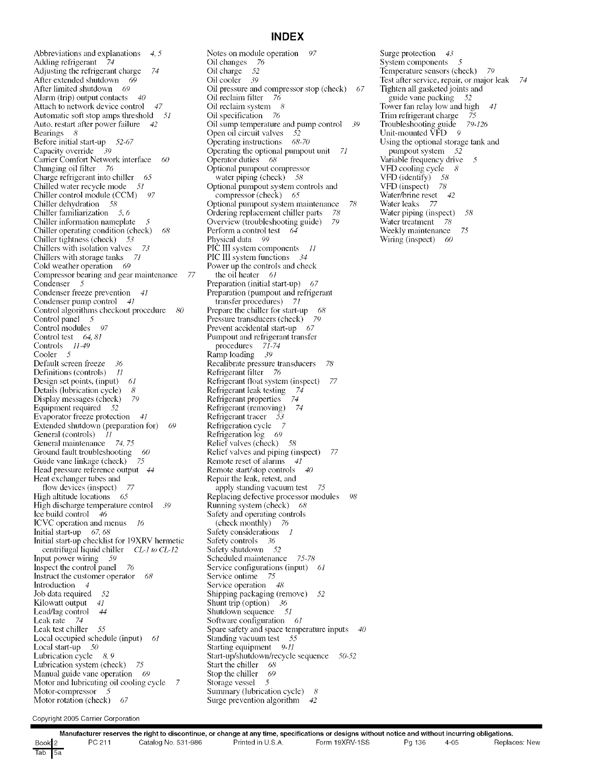
INDEX
Abbreviations and explanations 4, 5 Notes on module operation 97
Adding refrigerant 74 Oil changes 76
Adjusting the refrigerant charge 74 Oil charge .52
After extended shutdown 69 Oil cooler 39
Alter limited shutdown 69 Oil pressure _mdcompressor stop (check) 67
Alarm (trip) output contacts 40 Oil reclaim filter 76
Attach to network device control 47 Oil reclaim system 8
Automatic soft stop amps threshold 51 Oil specification 76
Auto. restart alter power failure 42 Oil sump temperature and pump control 39
Bearings 8Open oil circuit valves .52
Before initial start-up .52-67 Operating instructions 68-70
Capacity override .;9 Operating the optional pumpout unit 71
Carrier Comfort Network interface 60 Operator duties 68
Changing oil filter 76 Optional pumpout compressor
Charge refrigerant into chiller 65 water piping (check) 5_5'
Chilled water recycle mode 51 Optional pumpout system controls and
Chiller control module (CCM) 97 compressor(check) 65
Chiller dehydration 58 Optional pumpout system maintenance 78
Chiller familiarization 5, 6 Ordering replacement chiller parts 78
Chiller information nameplate 5Overview (troubleshooting guide) 79
Chiller operating condition (check) 68 Perform a control test 64
Chiller tightness (check) 53 Physical data 99
Chillers with isolation valves 73 PIC III system components 11
Chillers with storage tanks 71 PIC III system functions .;4
Cold weather operation 69 Power up the controls and check
Compressor bearing and gear maintenance 77 the oil heater 61
Condenser 5Preparation (initialstart-up) 67
Condenser freeze prevention 41 Preparation (pumpout and refrigerant
Condenser pump control 41 transfer procedures) 71
Control algorithms checkout procedure 80 Prepare the chiller for start-up 68
Controlpanel 5Pressure transducers (check) 79
Control modules 97 Prevent accidental start-up 67
Control test 64,81 Pumpont and refrigerant transfer
Controls 11-49 procedures 71-74
Cooler 5Ramp loading 39
Defimlt screen freeze .;6 Recalibmte pressure transducers 7,5'
Definitions (controls) 11 Refrigerant filter 76
Design set points, (input) 61 Refrigerant float system (inspect) 77
Details (lubrication cycle) 8Refrigerant leak testing 74
Display messages (check) 79 Refrigerant properties 74
Equipment required .52 Refrigerant (removing) 74
Evaporator freeze protection 41 Refrigerant tracer 53
Extended shutdown (preparation for) 69 Refrigeration cycle 7
General (controls) 11 Refrigeration log 69
General maintenance 74, 75 Relief valves (check) 58
Ground fault troubleshooting 60 Relief valves and piping (inspect) 77
Guide vane linkage (check) 7.5 Remote reset of alarms 41
Head pressure reference output 44 Remote start/stop controls 40
Heat exchanger tubes and Repair the leak, retest, and
flow devices (inspect) 77 apply standing vacuum test 7.5
High altitude locations 65 Replacing defective processor modules 98'
High discharge temperature control .;9 Running system (check) 68
Ice build control 46 Safety and operating controls
ICVC operation and menus 16 (check monthly) 76
Initial start-up 6Z 6_5' Safety considerations 1
Initial start-up checklist for 19XRV hermetic Safety controls .;6
centrifugal liquid chiller CL-lro CL-12 Safety shutdown 52
Input power wiring 59 Scheduled maintenance 75-78
Inspect the control panel 76 Service configurations (input) 61
Instruct the customer operator 68 Ser_.ice ontime 7.5
Introduction 4Seta.'ice operation 48'
Job data required .52 Shipping packaging (remove) .52
Kilowatt output 41 Shunt trip (option) 36
Lead/lag control 44 Shutdown sequence 51
Leak rate 74 Software configuration 61
Leak test chiller .5.5 Spare safety and space temperature inputs 40
Local occupied schedule (input) 61 Standing vacuum test 55
Local start-up 50 Starting equipment 9-11
Lubrication cycle 8, 9 Start-up/shutdown/recycle sequence 50-.52
Lubrication system (check) 7.5 Start the chiller 68
Manual guide vane operation 69 Stop the chiller 69
Motor and lubricating oil cooling cycle 7Storage vessel 5
Motor-compressor 5Sunnnary (lubrication cycle) 8
Motor rotation (check) 67 Surge prevention algorithm 42
Surge protection 43
System components 5
Temperature sensors (check) 79
Test after service, repair, or m:tior leak
Tighten all gasketed joints and
guide vane packing .52
Tower fan relay low and high 41
Trim refrigerant charge 7.5
Troubleshooting guide 79-126
Unit-mounted VFD 9
Using the optional storage tank and
pumpout system 52
Variable frequency drive 5
VFD cooling cycle 8
VFD (identify) 58
VFD (inspect) 78
Water/brine reset 42
Water leaks 77
Water piping (inspect) 58
Water treatment 78
Weekly nmintenance 7.5
Wiring (inspect) 60
74
Copyright 2005 Carrier Corporation
Manufacturer reserves the right to discontinue, or change at any time, specifications or designs without notice and without incurring obligations.
PC 211 Catalog No. 531-986 Printed in U.S.A. Form 19XRV-1SS Pg 136 4-05 Replaces: New
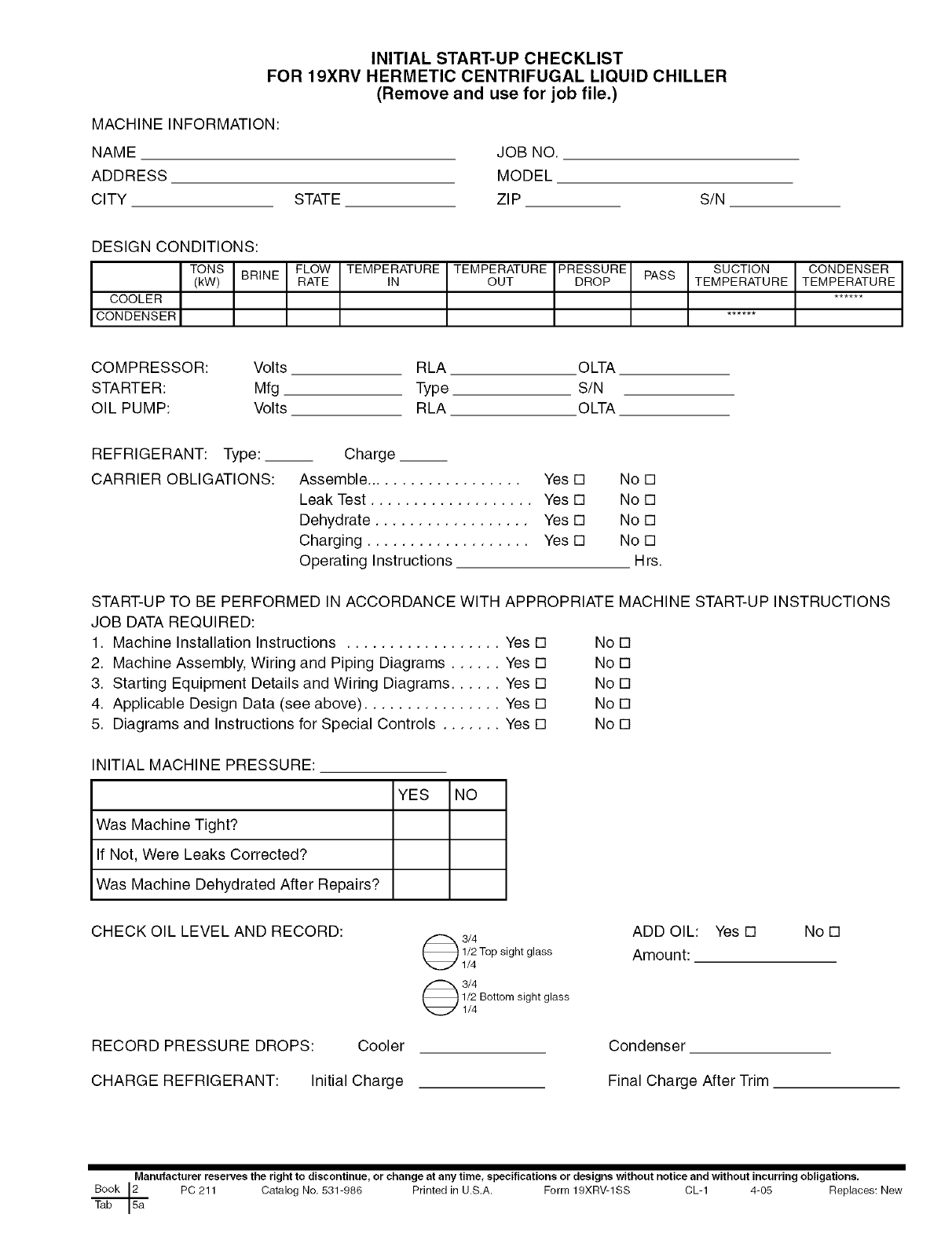
INITIAL START-UP CHECKLIST
FOR 19XRV HERMETIC CENTRIFUGAL LIQUID CHILLER
(Remove and use for job file.)
MACHINE INFORMATION:
NAME
ADDRESS
CITY STATE
JOB NO.
MODEL
ZIP S/N
DESIGN CONDITIONS:
TONS BRINE
(kW)
COOLER
CONDENSER
FLOW TEMPERATURE
RATE IN TEMPERATURE PRESSURE PASS SUCTION
OUT DROP TEMPERATURE CONDENSER
TEMPERATURE
COMPRESSOR: Volts
STARTER: Mfg
OIL PUMP: Volts
RLA OLTA
Type S/N
RLA OLTA
REFRIGERANT: Type: __
CARRIER OBLIGATIONS:
Charge __
Assemble ................... Yes [] No []
Leak Test ................... Yes [] No []
Dehydrate .................. Yes [] No []
Charging ................... Yes [] No []
Operating Instructions Hrs.
START-UP TO BE PERFORMED IN ACCORDANCE WITH APPROPRIATE MACHINE START-UP INSTRUCTIONS
JOB DATA REQUIRED:
1. Machine Installation Instructions .................. Yes [] No []
2. Machine Assembly, Wiring and Piping Diagrams ...... Yes [] No []
3. Starting Equipment Details and Wiring Diagrams ...... Yes [] No []
4. Applicable Design Data (see above) ................ Yes [] No []
5. Diagrams and Instructions for Special Controls ....... Yes [] No []
INITIAL MACHINE PRESSURE:
YES NO
Was Machine Tight?
If Not, Were Leaks Corrected?
Was Machine Dehydrated After Repairs?
CHECK OIL LEVEL AND RECORD:
RECORD PRESSURE DROPS: Cooler
CHARGE REFRIGERANT: Initial Charge
3/4
1/2 Top sight glass
1/4
3/4
1/2 Bottom sight glass
1/4
ADD OIL: Yes []
Amount:
No []
Condenser
Final Charge After Trim
Manufacturer reserves the right to discontinue, or change at any time_ specifications or designs without notice and without incurring obligations.
Book 2h PC 211 Catalog No, 531-986 Printed in U.S,A. Form 19XRV-1SS CL-1 4-05 Replaces: New
F
Tab
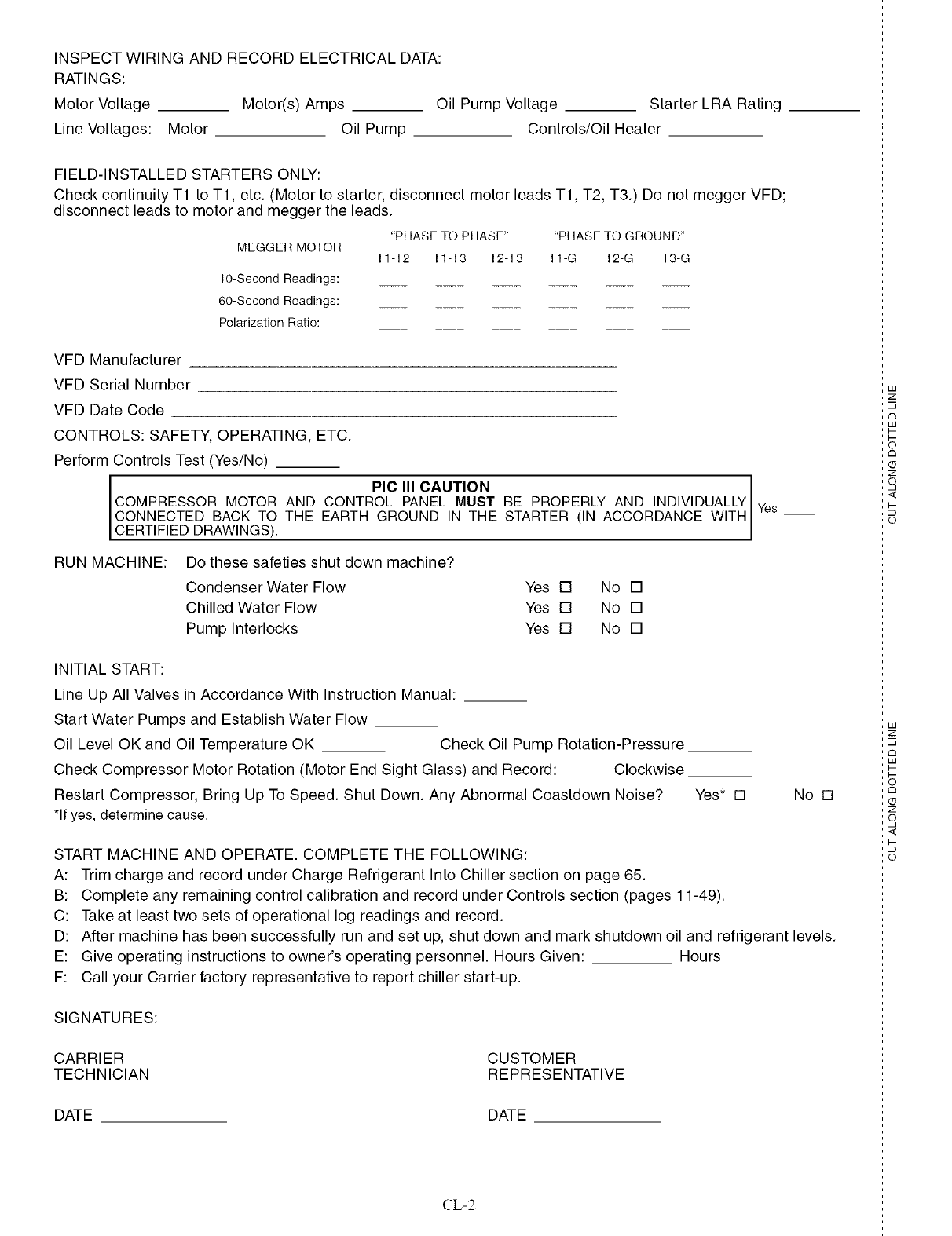
INSPECT WIRING AND RECORD ELECTRICAL DATA:
RATINGS:
Motor Voltage Motor(s) Amps Oil Pump Voltage Starter LRA Rating
Line Voltages: Motor Oil Pump Controls/Oil Heater
FIELD-INSTALLED STARTERS ONLY:
Check continuity T1 to T1, etc. (Motor to starter, disconnect motor leads T1, T2, T3.) Do not megger VFD;
disconnect leads to motor and megger the leads.
MEGGER MOTOR "PHASE TO PHASE .... PHASE TO GROUND"
T1 -T2 T1 -T3 T2-T3 T1-G T2-G T3-G
10-Second Readings:
60-Second Readings:
Polarization Ratio:
VFD Manufacturer
VFD Serial Number
VFD Date Code
CONTROLS: SAFETY, OPERATING, ETC.
Perform Controls Test (Yes/No)
PIC III CAUTION
COMPRESSOR MOTOR AND CONTROL PANEL MUST BE PROPERLY AND INDIVIDUALLY
CONNECTED BACK TO THE EARTH GROUND IN THE STARTER (IN ACCORDANCE WITH
CERTIFIED DRAWINGS).
RUN MACHINE: Do these safeties shut down machine?
Condenser Water Flow Yes [] No []
Chilled Water Flow Yes [] No []
Pump Interlocks Yes [] No []
Yes
INITIAL START:
Line Up All Valves in Accordance With Instruction Manual:
Start Water Pumps and Establish Water Flow
Oil Level OK and Oil Temperature OK Check Oil Pump Rotation-Pressure
Check Compressor Motor Rotation (Motor End Sight Glass) and Record: Clockwise
Restart Compressor, Bring Up To Speed. Shut Down. Any Abnormal Coastdown Noise?
*If yes, determine cause.
Yes* [] No []
START MACHINE AND OPERATE. COMPLETE THE FOLLOWING:
A: Trim charge and record under Charge Refrigerant Into Chiller section on page 65.
B: Complete any remaining control calibration and record under Controls section (pages 11-49).
C: Take at least two sets of operational log readings and record.
D: After machine has been successfully run and set up, shut down and mark shutdown oil and refrigerant levels.
E: Give operating instructions to owner's operating personnel. Hours Given: Hours
F: Call your Carrier factory representative to report chiller start-up.
SIGNATURES:
CARRIER
TECHNICIAN CUSTOMER
REPRESENTATIVE
DATE DATE
CL-2
U3
z
u
c_
U3
c_
z
q
I-
o
LU
2:
u
tm
LU
I-
c_
Z
o,
I-
o
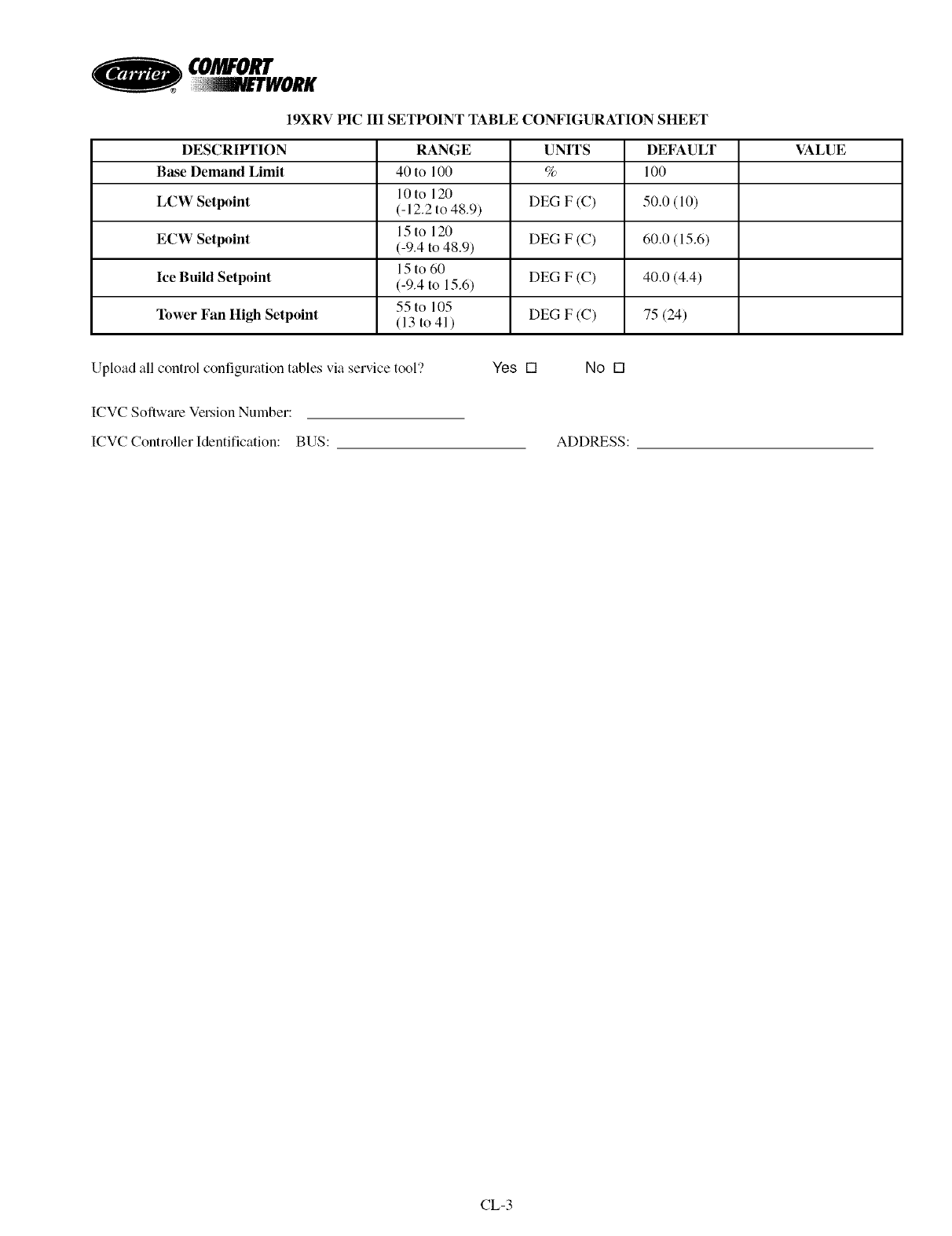
CO/WO
19XRV PIC III SETPOINT 3ABLE CONFIGURATION StIEET
DESCRIlrrlON RANGE UNITS DEFAULT VALUE
Base Demand Limit 40 to 100 %100
10to 120
LCW Setpoint (- 12.2 to 48.9) DEG F (C) 50.0 (10)
15to 120
ECW Setpoint (-9.4 to 48.9) DEG F (C) 60.0 (15.6)
15 to 60
Ice Build Setpoint (-9.4 to 15.6) DEG F (C) 40.0 (4.4)
55 to 105
Tower Fan Itigh Setpoint (13 to 41 ) DEG F (C) 75 (24)
Upload all control configuration tables via service tool'? Yes [] No []
ICVC Softwme Version Number:
ICVC Controller Identification: BUS: ADDRESS:
CL-3
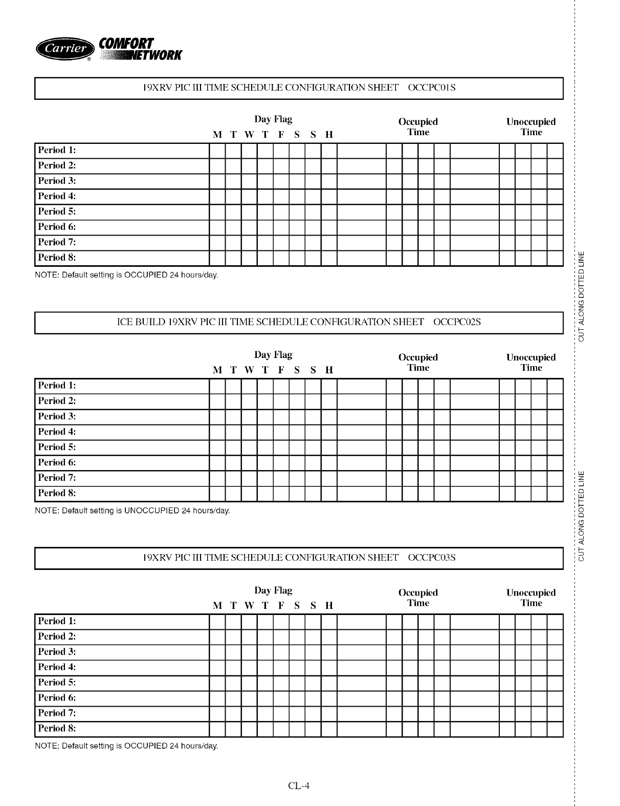
O
I
Period 1:
Period 2:
Period 3:
Period 4:
Period 5:
Period 6:
Period 7:
19XRV PIC III TIME SCHEDULE CONFIGURATION SHEET OCCPC01S
Day Flag Occupied
M T W T F S S II Time
Period 8:
NOTE: Default setting isOCCUPIED 24 hours/day.
IICE BUILD 19XRV PIC III TIME SCHEDULE CONFIGURATION SHEET OCCPC02S
Period 1:
Period 2:
Period 3:
Period 4:
Period 5:
Period 6:
Period 7:
Period 8:
Unoccupied
Time
NOTE: Default setting is UNOCCUPIED 24 hours/day.
I
Day Flag Occupied Unoccupied
M T W T F S S It Time Time
19XRV PIC III TIME SCHEDULE CONFIGURATION SHEET OCCPC03S
Day Flag Occupied Unoccupied
M T W T F S S It Time Time
CL-4
I
Period 1:
Period 2:
Period 3:
Period 4:
Period 5:
Period 6:
Period 7:
Period 8:
NOTE: Default setting isOCCUPIED 24 hours/day.
I
I
LU
z
m
c_
LU
i-
tm
z
o,
I-
o
LU
z
m
tm
LU
I-
Z
o,
I-
o
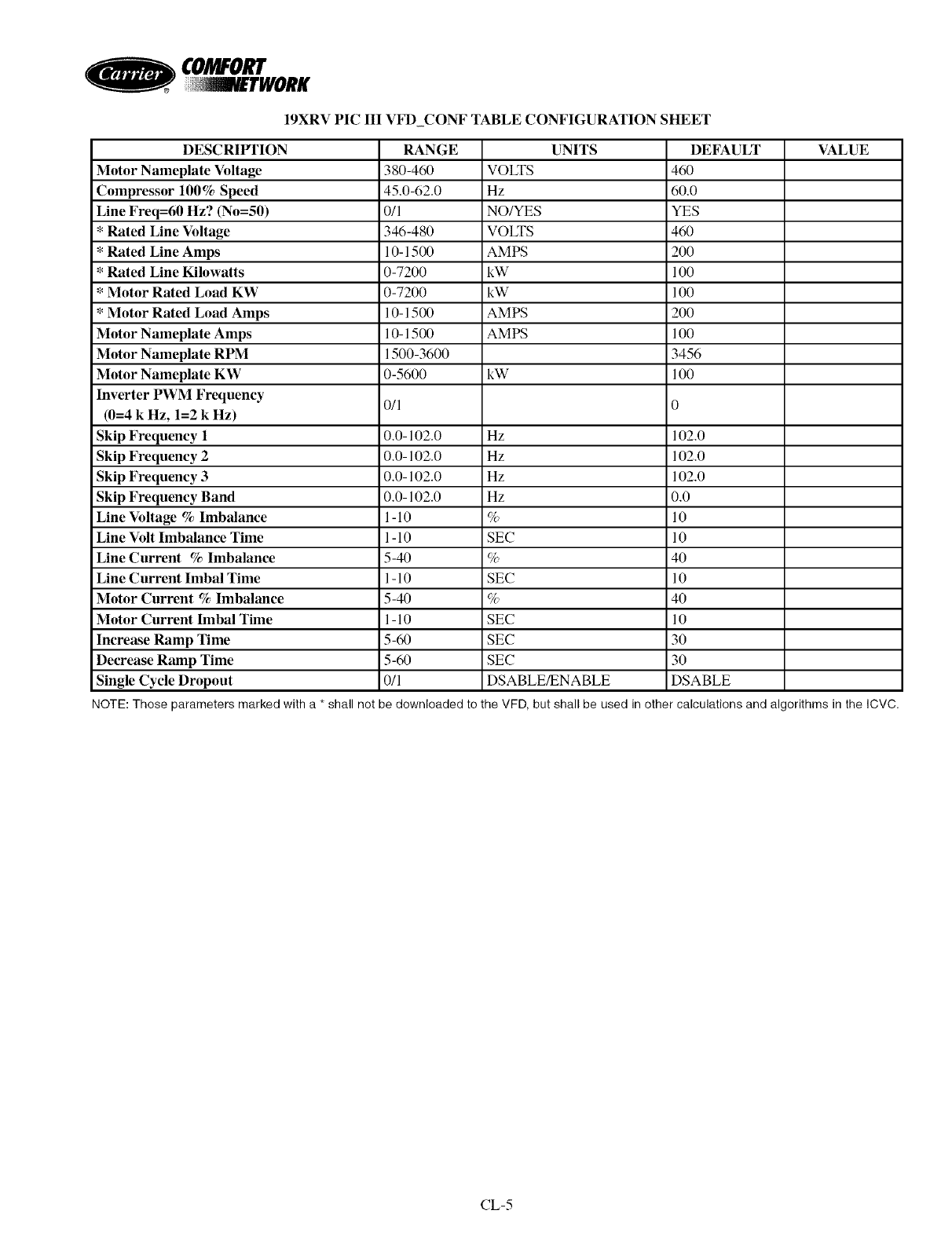
19XRV PIC III VFD_CONF TABLE CONFIGURATION SIIEET
DESCRIIrFION RANGE UNITS DEFAULT VALUE
Motor Nameplate Voltage 380-460 VOLTS 460
Compressor 100% Speed 45.0-62.0 Hz 60.0
Line Freq=60 Hz? (No=50) 0/l NO/YES YES
* Rated Line Voltage 346-480 VOLTS 460
* Rated Line Amps l 0-1500 AMPS 200
* Rated Line Kilowatts 0-7200 kW 100
* Motor Rated Load KW 0-7200 kW 100
* Motor Rated Load Amps 10-1500 AMPS 200
Motor Nameplate Amps l 0-1500 AMPS 100
Motor Nameplate RPM 1500-3600 3456
Motor Nameplate KW 0-5600 kW 100
Inverter PWM Frequency 0/l 0
(0=4 k Hz, 1=2 k Hz)
Skip Frequency I 0.0-102.0 Hz 102.0
Skip Frequency 2 0.0-102.0 Hz 102.0
Skip Frequency 3 0.0-102.0 Hz 102.0
Skip Frequency Band 0.0-102.0 Hz 0.0
Line Voltage % Imbalance l -l0 % l0
Line Volt Imbalance Time l -l0 SEC l0
Line Current % Imbalance 5-40 % 40
Line Current Imbal Time l-l0 SEC l0
Motor Current % Imbalance 5-40 % 40
Motor Current Imbal Time l - l0 SEC l0
Increase Ramp Time 5-60 SEC 30
Decrease Ramp Time 5-60 SEC 30
Single Cycle Dropout 0/l DSABLE/ENABLE DSABLE
NOTE: Those parameters marked with a * shall not be downloaded to the VFD, but shall be used in other calculations and algorithms in the ICVC.
CL-5
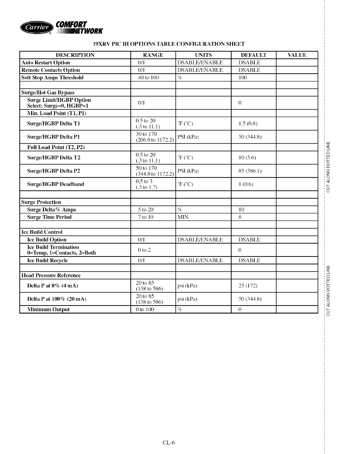
O
19XRV PIC HI OIq'IONS TABLE CONFIGURATION SIIEET
DESCRIF1TON
Auto Restart Option
Remote Contacts Option
Soft Stop Amps Threshold
Surge/llot Gas Bypass
Surge Limit/HGBP Option
Select: Surge=0, HGBP=I
Min. Load Point (T1, P1)
Surge/ItGBP Delta T1
Surge/ItGBP Delta P1
Full Load Point (T2, P2)
Surge/ltGBP Delta T2
Surge/IR_BP Delta P2
Surge/liGBP Deadband
Surge Protection
Surge Delta% Amps
Surge Time Period
Ice Build Control
Ice Build Option
Ice Build Termination
0=Temp, l=Contacts, 2=Both
Ice Build Recycle
Iiead Pressure Reference
Delta Pat 0% (4 mA)
Delta P at 100% (20 mA)
Minimum Output
RANGE
0/1
0/1
40 to 100
0/1
0.5 to 20
(.3to 11.1)
30 to 170
(206.9 to 1172.2)
0.5 to 20
(.3to 11.1)
50 to 170
(344.8 to 1172.2)
0.5 to 3
(.3 to 1.7)
5to 20
7to 10
0/1
Oto 2
0/1
20 to 85
(138 to 586)
20 to 85
(138 to 586)
0 to 100
UNITS
DSABLE/ENABLE
DSABLE/ENABLE
%
^F fie)
PSI (kPa)
^F fie)
PSI (kPa)
^F (^C)
%
MIN
DSABLE/ENABLE
DSABLE/ENABLE
psi (kPa)
psi (kPa)
%
DEFAULT
DSABLE
DSABLE
100
1.5(0.8)
50 (344.8)
10 (5.6)
85 (586.1)
1 (0.6)
10
8
DSABLE
0
DSABLE
25 (172)
50 (344.8)
0
VALUE
LI3
z
m
C3
LI3
z
S
.<
D
o
HA
z
m
C3
HA
C3
(9
Z
o,
<
D
o
CL-6
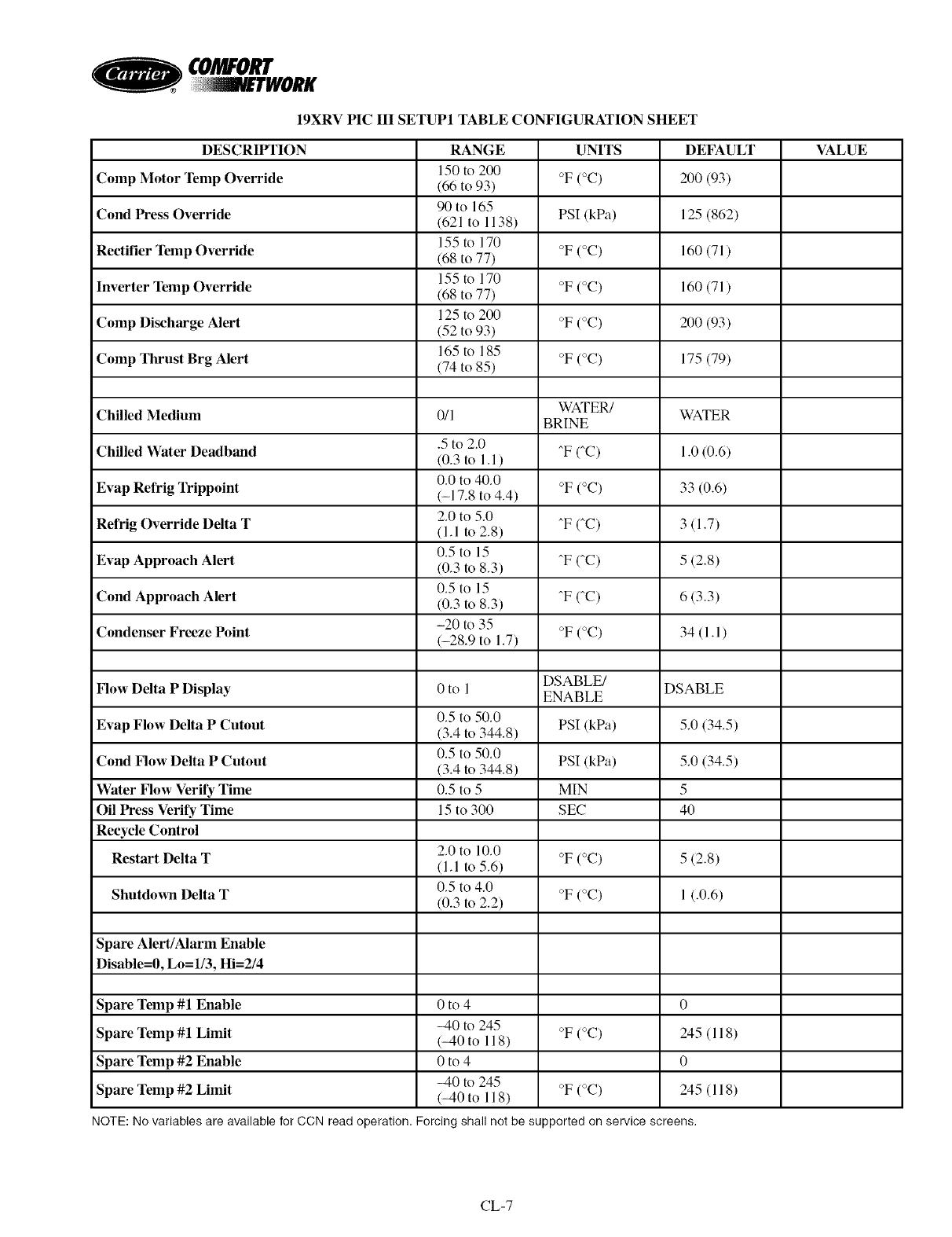
CO/WO
19XRV PIC IIl SETUP1 TABLE CONFIGURATION SttEET
DESCRHrl'ION RANGE UNITS DEFAULT VALUE
Comp Motor Temp Override 150 to 200
(66 to 93) °F (°C) 200 (93)
Cond Press Override 90 to 165
(621 to 1138) PSI (kPa) 125 (862)
155 to 170
Rectifier Temp Override (68 to 77) °F (°C) 160 (71)
155 to 170
Inverter Temp Override (68 to 77) °F (°C) 160 (71)
125 to 200
Comp Discharge Alert (52 to 93) °F (°C) 200 (93)
165 to 185
Comp Thrust Brg Alert (74 to 85) °F (°C) 175 (79)
WATER/
Chilled Medium 0/1 WATER
BRINE
.5 to 2.0
Chilled Water Deadband (0.3 to 1.1) T (_C) 1.0 (0.6)
0.0 to 40.0
Evap Refrig Trippoint (-17.8 to 4.4) °F (°C) 33 (0.6)
2.0 to 5.0
Refrig Override Delta T (1.1 to 2.8) T (_C) 3 (1.7)
0.5 to 15
Evap Approach Alert (0.3 to 8.3) T CC) 5 (2.8)
0.5 to 15
Cond Approach Alert (0.3 to 8.3) T (_C) 6 (3.3)
Condenser Freeze Point -20 to 35
(-28.9 to 1.7) °F (°C) 34(1.1)
DSABLE/
Flow Delta P Display 0 to 1 ENABLE DSABLE
Evap Flow Delta P Cutout 0.5 to 50.0
(3.4 to 344.8) PSI (kPa) 5.0 (34.5)
Cond Flow Delta P Cutout 0.5 to 50.0
(3.4 to 344.8) PSI (kPa) 5.0 (34.5)
Water Flow Verify Time 0.5 to 5 MIN 5
Oil Press Verify Time 15 to 300 SEC 40
Recycle Control
2.0 to 10.0
Restart Delta T (1.1 to 5.6) °F (°C) 5 (2.8)
Shutdown Delta T 0.5 to 4.0
(0.3 to 2.2) °F (°C) 1 (.0.6)
Spare Alert/Alarm Enable
Disable=0, Lo=l/3, Iii=214
Spare Temp #1 Enable 0 to 4 0
Spare Temp #1 Limit _40 to 245
(_40 to 118) °F (°C) 245 (118)
Spare Temp #2 Enable 0 to 4 0
Spare Temp #2 Limit _40 to 245
(_40 to 118) °F (°C) 245 (118)
NOTE:Novariablesareavailablefor CCNreadoperation. Forcing shallnotbesupported on servicescreens.
CL-7
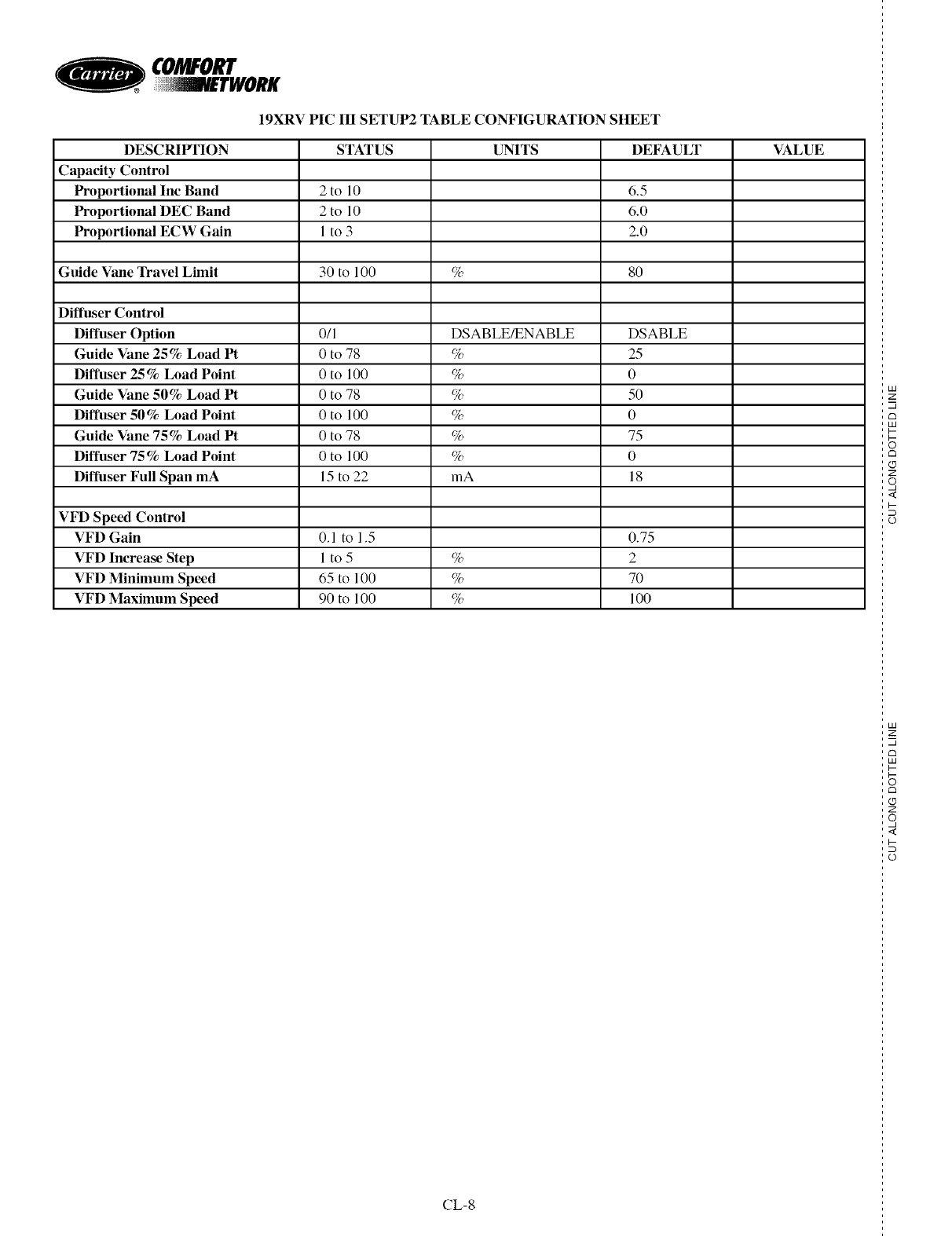
O
19XRV PIC IH SETUP2 TABLE CONFIGURATION SIIEET
DESCRIPFION STATUS UNITS DEFAULT VALUE
Capacity Control
Proportional Inc Band 2 to 10 6.5
Proportional DEC Band 2 to 10 6.0
Proportional ECW Gain I to 3 2.0
Guide Vane Travel Limit 30 to 100 % 80
Diffuser Control
Diffuser Option 0/1 DSABLE/ENABLE DSABLE
Guide Vane 25% Load Pt 0to 78 %25
Diffuser 25% Load Point 0to 100 % 0
Guide Vane 50% Load Pt 0to 78 % 50
Diffuser 50% Load Point 0to 100 % 0
Guide Vane 75% Load Pt 0to 78 % 75
Diffuser 75% Load Point 0to 100 %0
Diffuser Full Span mA 15 to 22 mA 18
VFD Speed Control
VFD Gain 0.1 to 1.5 0.75
VFD Increase Step 1 to 5 % 2
VFD Minimum Speed 65 to 100 % 70
VFD Maximum Speed 90 to 100 % 100
CL-8
U3
z
m
u3
z
q
D
L)
U3
z
m
u3
Z
q
L)
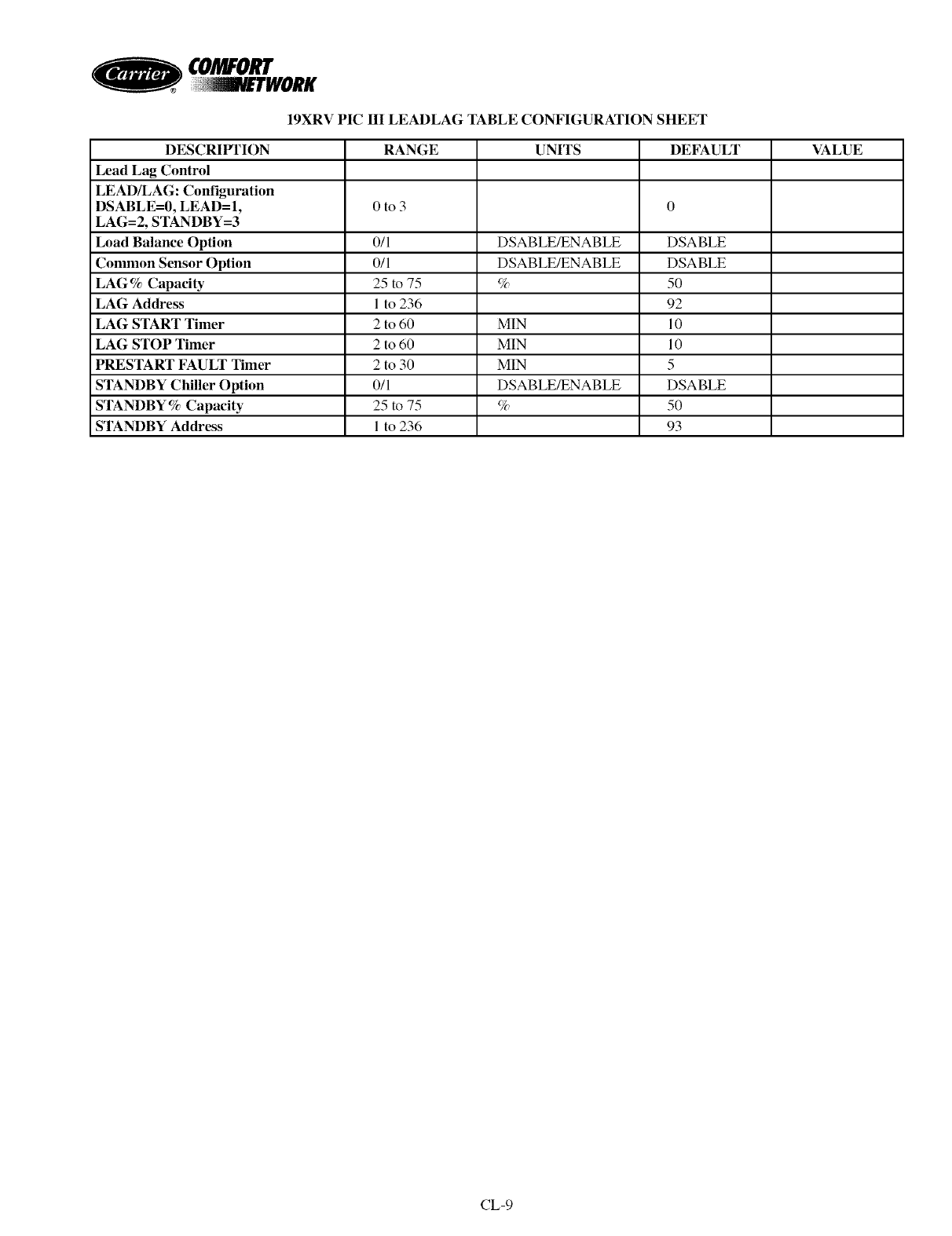
CO/WO
19XRV PIC HI LEADLAG TABLE CONFIGURATION StlEET
DESCRIF1TON RANGE UNITS DEFAULT VALUE
Lead Lag Control
LEAD/LAG: Configuration
DSABLE=0, LEAD=l, 0 to 3 0
LAG=2, STANDBY=3
Load Balance Option 0/1 DSABLE/ENABLE DSABLE
Common Sensor Option 0/1 DSABLE/ENABLE DSABLE
LAG% Capacity 25 to 75 % 50
LAG Address 1 to 236 92
LAG START Timer 2 to 60 MIN 10
LAG STOP Timer 2 to 60 MIN 10
PRESTART FAULT Timer 2 to 30 MIN 5
STANDBY Chiller Option 0/1 DSABLE/ENABLE DSABLE
STANDBY% Capacity 25 to 75 % 50
STANDBY Address I to 236 93
CL-9
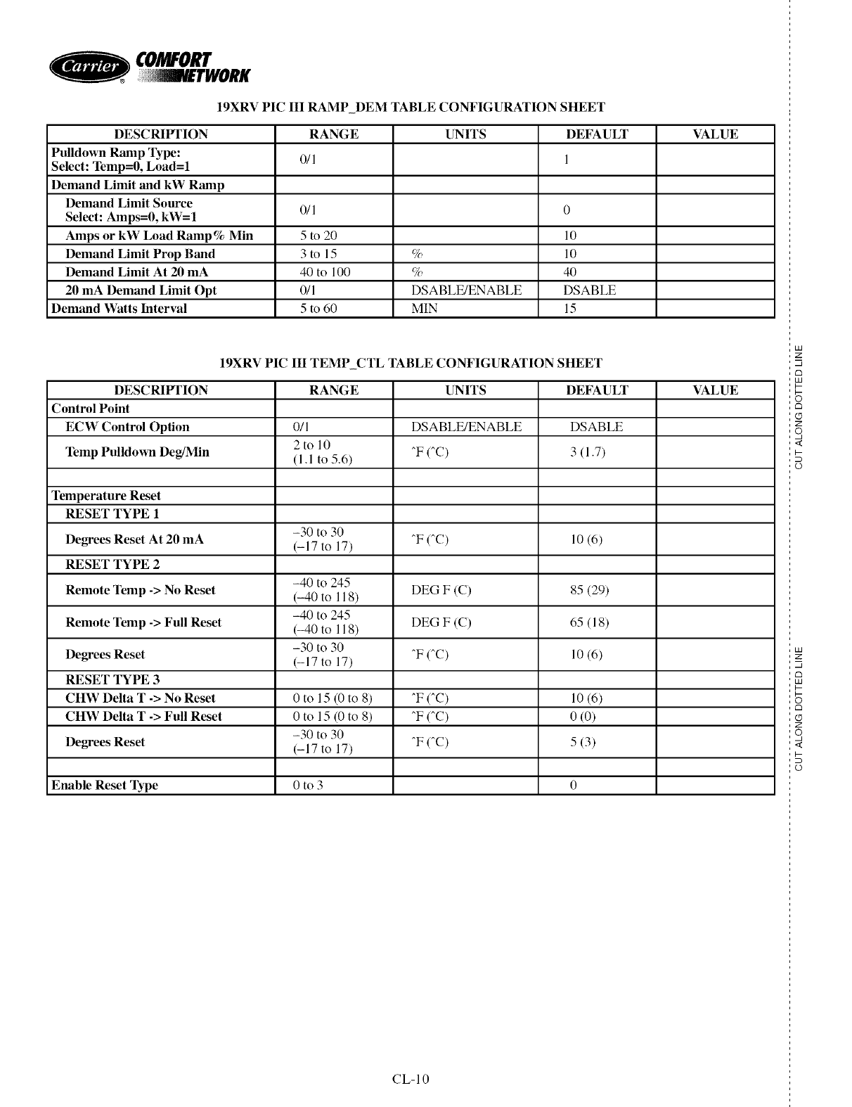
O
19XRV PIC III RAMP_DEM TABLE CONFIGURATION SIIEET
DESCRIFI'ION RANGE UNITS DEFAULT VALUE
Pulldown Ramp Type: 0/1 1
Select: Temp=0, Load=l
Demand Limit and kW Ramp
Demand Limit Source 0/1 0
Select: Amps=0, kW= 1
Amps or kW Load Ramp% Min 5 to 20 10
Demand Limit Prop Band 3 to 15 % 10
Demand Limit At 20 mA 40 to 100 % 40
20 mA Demand Limit Opt 0/1 DSABLE/ENABLE DSABLE
Demand Watts Interval 5 to 60 MIN 15
19XRV PIC Ill TEMP_CTL TABLE CONFIGURATION SIIEET
DESCRIlrl'ION RANGE UNITS DEFAULT VALUE
Control Point
ECW Control Option 0/1 DSABLE/ENABLE DSABLE
2to 10
Temp Pulldown Deg/Min (1.1 to 5.6) ^F (^C) 3 (1.7)
Temperature Reset
RESET TYPE 1
-30 to 30
Degrees Reset At 20 mA (-17 to 17) ^F (_C) 10 (6)
RESET TYPE 2
-40 to 245
Remote Temp -> No Reset (-40 to 118) DEG F (C) 85 (29)
-40 to 245
Remote Temp -> Full Reset (-40 to 118) DEG F (C) 65 (18)
-30 to 30
Degrees Reset (-17 to 17) ^F (^C) 10 (6)
RESET TYPE 3
CIIW Delta T -> No Reset 0 to 15 (0 to 8) ^F (_C) 10 (6)
CIIW Delta T -> Full Reset 0 to 15 (0 to 8) _F (_C) 0 (0)
-30 to 30
Degrees Reset (-17 to 17) ^F (_C) 5 (3)
Enable Reset Type 0 to 3 0
CL-10
lad
z
m
lad
_3
Z
o,
<
lad
z
m
_3
lad
Z
o,
<
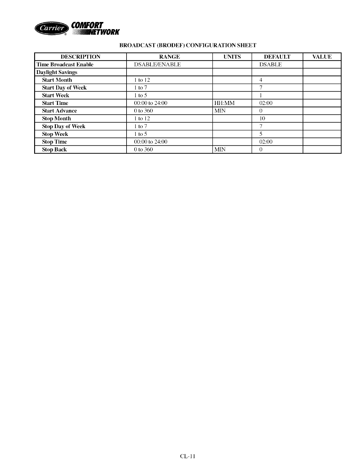
CO/WO
BROADCAST (BRODEF) CONFIGURATION StlEET
DESCRIF1TON RANGE UNITS DEFAULT VALUE
Time Broadcast Enable DSABLE/ENABLE DSABLE
Daylight Savings
Start Month I to 12 4
Start Day of Week 1 to 7 7
Start \¥eek 1 to 5 1
Start Time 00:00 to 24:00 HH:MM 02:00
Start Advance 0 to 360 MIN 0
Stop Month 1 to 12 10
Stop Day of Week 1 to 7 7
Stop Week 1 to 5 5
Stop Time 00:00 to 24:00 02:00
Stop Back 0 to 360 MIN 0
CL-II
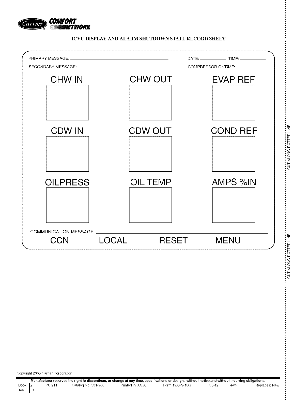
CO/_O_
ICVC DISPLAY AND ALARM SItUTDOWN STATE RECORD SIIEET
fPRIMARY MESSAGE:
SECONDARY MESSAGE:
CHW IN CHW OUT
DATE: TIME:
COMPRESSOR ONTIME:
EVAP REF
CDW IN CDW OUT COND REF
OILPRESS OILTEMP AMPS %IN
COMMUNICATION MESSAGE
CCN LOCAL RESET MENU J
Copyright 2005 Carrier Corporation
Manufacturer reserves the right to discontinue, or change at any time, specifications or designs without notice and without incurring obligations.
Book 2J2 PC 211 Catalog No. 531-988 Printed in U.SA. Form 19XRV-1SS CL-12 4-05 Replaces: New
F
Tab
LU
z
u
C3
LU
tm
Z
o,
<
i-
o
LU
2:
u
rm
LU
I-
S
c_
Z
o,
<
i-
o
