CARRIER Controls And HVAC Accessories Manual L0601172
User Manual: CARRIER CARRIER Controls and HVAC Accessories Manual CARRIER Controls and HVAC Accessories Owner's Manual, CARRIER Controls and HVAC Accessories installation guides
Open the PDF directly: View PDF ![]() .
.
Page Count: 6
Installation Instructions
NOTE: Read the entire instruction manual before starting the
installation.
SAFETY CONSIDERATIONS
Installation and servicing of this equipment can be hazardous
due to mechanical and electrical components. Only trained
and qualified personnel should install, repair, or service this
equipment.
Untrained personnel can perform basic maintenance func-
tions such as cleaning and replacing air filters. All other opera-
tions must be performed by trained service personnel. When
working on this equipment, observe precautions in the litera-
ture, on tags, and on labels attached to or shipped with the
unit and other safety precautions that may apply.
Follow all safety codes. Installation must be in compliance
with local and national building codes. Wear safety glasses,
protective clothing, and work gloves. Have fire extinguisher
available. Read these instructions thoroughly and follow all
warnings or cautions included in literature and attached to the
unit.
Recognize safety information. This is the safety-alert symbol z_.
When you see this symbol on the unit and in instructions or
manuals, be alert to the potential for personal injury. Under-
stand these signal words; DANGER, WARNING, and CAU-
TION. These words are used with the safety-alert symbol.
DANGER identifies the most serious hazards which will result
in severe personal injury or death. WARNING signifies haz-
ards which could result in personal injury or death. CAUTION
is used to identify unsafe practices which may result in minor
personal injury or product and property damage. NOTE is
used to highlight suggestions which will result in enhanced
installation, reliability, or operation.
Follow all safety codes. Wear safety glasses and work gloves.
Have a fire extinguisher available.
Before proceeding with installation, inspect thoroughly for
shipping damage. Notify shipper immediately if any damage
is found. Check for proper clearances of moving parts.
The qualified installer or agency must use factory- authorized
kits or accessories when modifying this product. Refer to the
individual instructions packaged with the kits or accessories
when installing.
INTRODUCTION
Slip-in style dampers are designed for easy installation in
rectangular ductwork on residential new construction or retro-
fit applications. A 24vac, direct-drive actuator is used for
smooth, quiet performance.
ELECTRICAL SHOCK HAZARD
Failure to follow this warning could result in personal
injury or death.
Before performing installation, service or maintenance
operations on this system, turn off all main power
switches and/or disconnects. There may be more than
1 disconnect switch. Turn off accessory heater power
switch if applicable. Lock out and tag switch with a
suitable warning label.
INSTALLATION CONSIDERATIONS
1. Place dampers away from areas that may be noise
sensitive. It is recommended to install zone dampers
near furnace plenum when possible. This may help
ease installation, as well as dissipate air noise
associated with zoning.
2. Install dampers in rectangular or square duct systems
only. Any frame misalignment will jam damper blades.
3. Install dampers so actuator is visible for inspection and
accessible in the event it would ever need service.
4. Use sheet metal screws to secure damper in ductwork
(do not try to weld dampers in any way).
5. To ensure proper fit and operation dampers must be
sized according to ductwork. Dampers are made
slightly smaller than nominal duct dimensions (See
Table 1).
UNIT OPERATION HAZARD
Failure to follow this caution may result in equipment dam-
age or improper operation.
Never force dampers into an undersized duct system. The
excess pressure can cause damper blades to jam.
NOTE: All dampers must be properly installed and supported
according to local codes or SMACNA standards. Seal duct
joints using duct tape, mastic, or other approved methods. Do
not allow mastic to come in contact with actuator.
INSTALLATION
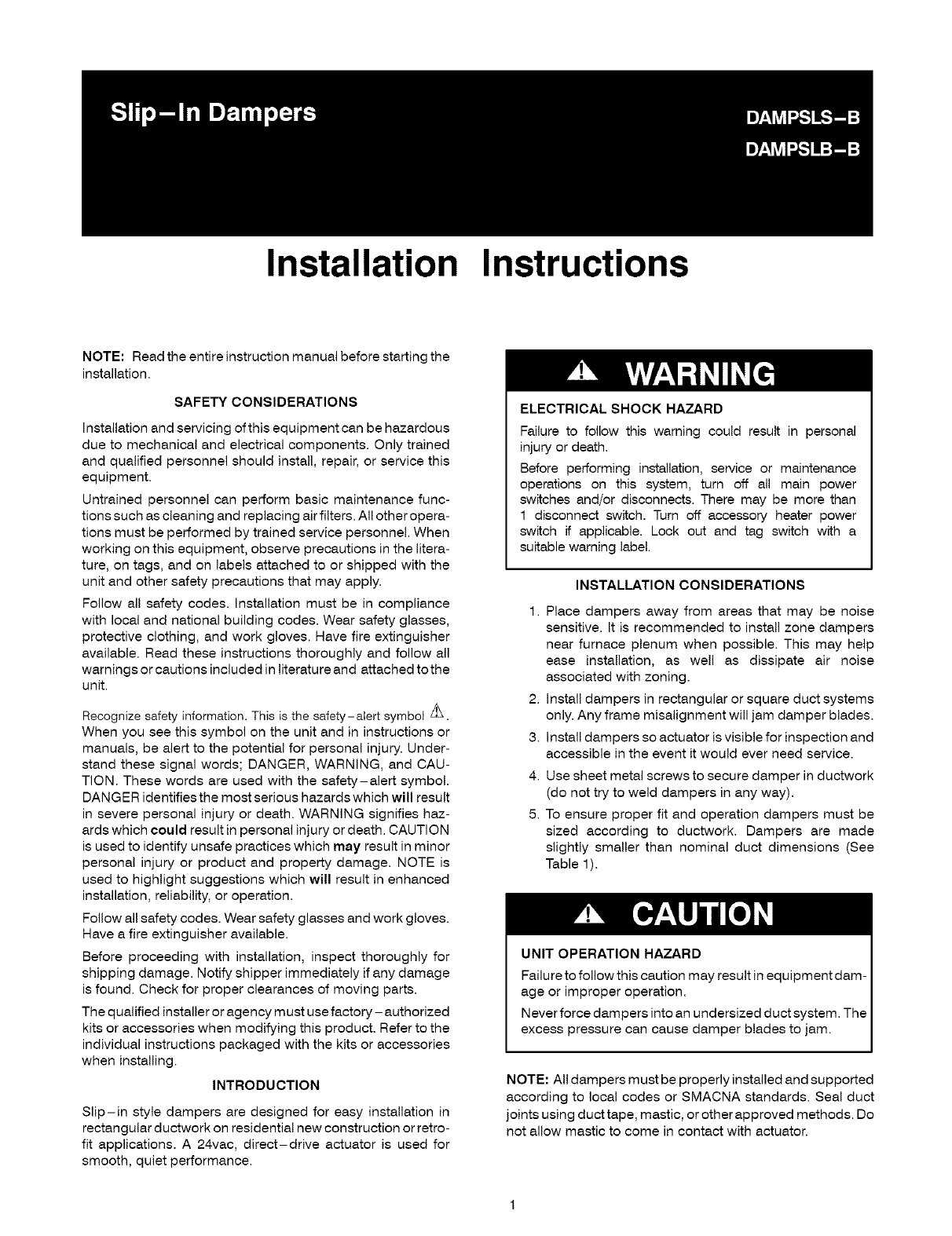
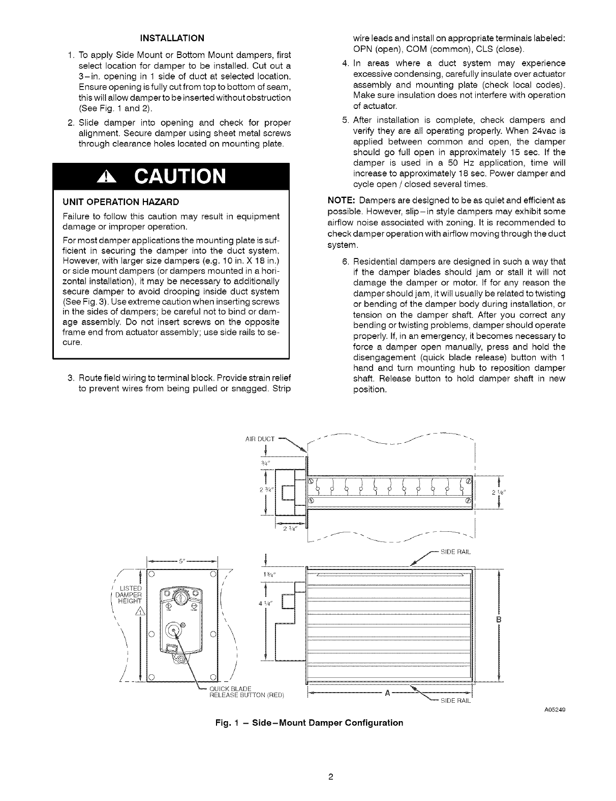
1. To apply Side Mount or Bottom Mount dampers, first
select location for damper to be installed. Cut out a
3-in. opening in 1 side of duct at selected location.
Ensure opening is fully cut from top to bottom of seam,
this will allow damper to be inserted without obstruction
(See Fig. 1 and 2).
2. Slide damper into opening and check for proper
alignment. Secure damper using sheet metal screws
through clearance holes located on mounting plate.
UNIT OPERATION HAZARD
Failure to follow this caution may result in equipment
damage or improper operation.
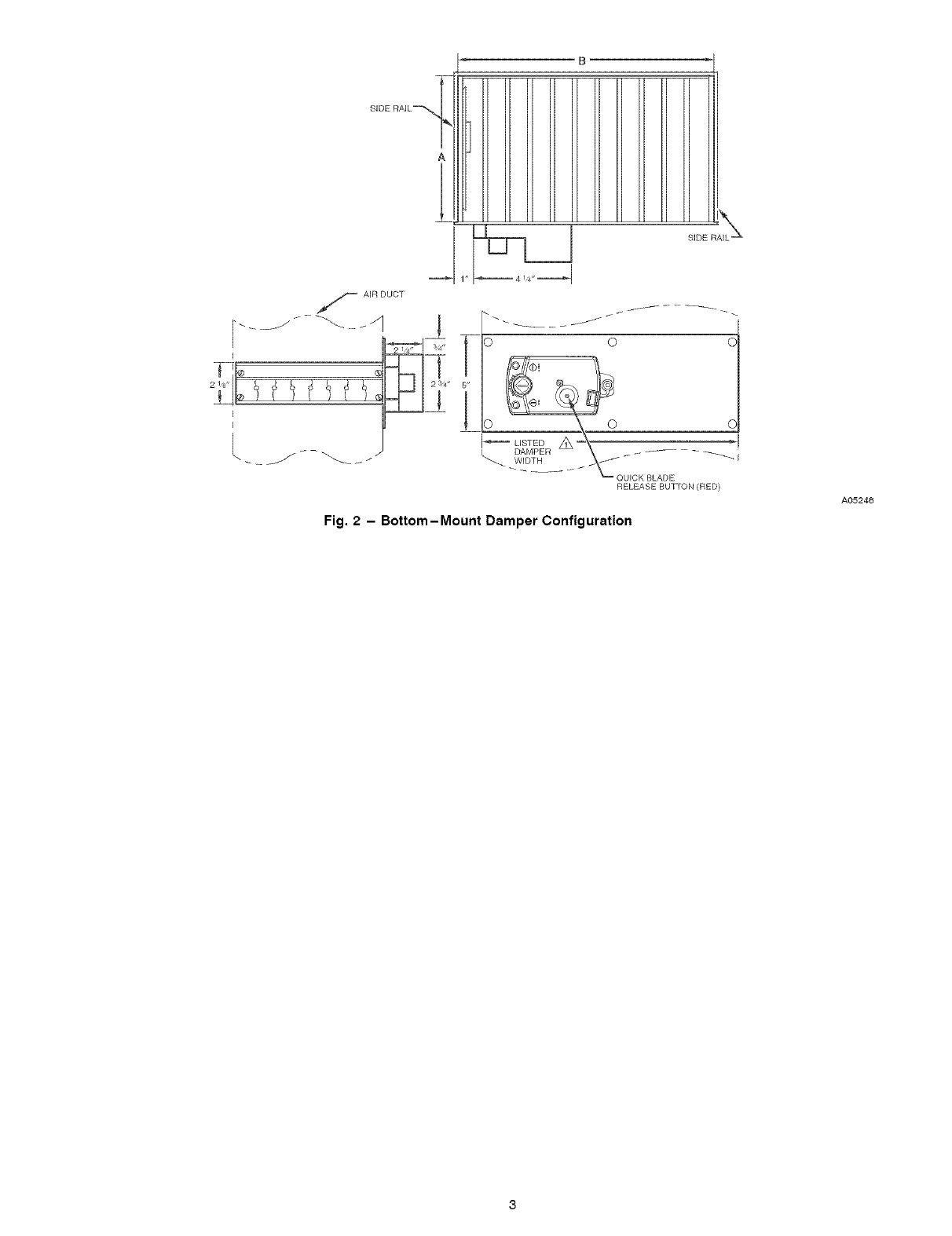
For most damper applications the mounting plate is suf-
ficient in securing the damper into the duct system.
However, with larger size dampers (e.g. 10 in. X 18 in.)
or side mount dampers (or dampers mounted in a hori-
zontal installation), it may be necessary to additionally
secure damper to avoid drooping inside duct system
(See Fig. 3). Use extreme caution when inserting screws
in the sides of dampers; be careful not to bind or dam-
age assembly. Do not insert screws on the opposite
frame end from actuator assembly; use side rails to se-
cure.
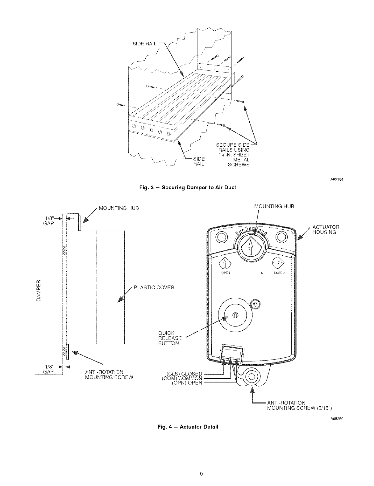
3. Routefieldwiringtoterminalblock. Provide strain relief
to prevent wires from being pulled or snagged. Strip
wire leads and install on appropriate terminals labeled:
OPN (open), COM (common), CLS (close).
4. In areas where a duct system may experience
excessive condensing, carefully insulate over actuator
assembly and mounting plate (check local codes).
Make sure insulation does not interfere with operation
of actuator.
5. After installation is complete, check dampers and
verify they are all operating properly. When 24vac is
applied between common and open, the damper
should go full open in approximately 15 sec. If the
damper is used in a 50 Hz application, time will
increase to approximately 18 sec. Power damper and
cycle open /closed several times.
NOTE: Dampers are designed to be as quiet and efficient as
possible. However, slip-in style dampers may exhibit some
airflow noise associated with zoning. It is recommended to
check damper operation with airflow moving through the duct
system.
6. Residential dampers are designed in such a way that
if the damper blades should jam or stall it will not
damage the damper or motor. If for any reason the
damper should jam, it will usually be related to twisting
or bending of the damper body during installation, or
tension on the damper shaft. After you correct any
bending or twisting problems, damper should operate
properly. If, in an emergency, it becomes necessary to
force a damper open manually, press and hold the
disengagement (quick blade release) button with 1
hand and turn mounting hub to reposition damper
shaft. Release button to hold damper shaft in new
position.
/_T 0
/LISTED
\ °
Ci ! 1_4"
i/
I
QUICK BLAr)E
RELEASE BUTTON (RED)
f --
/_ SIDE RAIL
Fig. 1 - Side-Mount Damper Configuration
2 l,g'
A05249
B
i
O ©O
_ LISTED Z_--_ _1
DAMPER \_" _ "_-- -- -- _ I
WIDTH
----- "_ QUICK BLADE
RELEASE BUTTON (RED)
Fig. 2 - Bottom-Mount Damper Configuration
AO5248

Catalog number A B
DAM PSLS08X08- B 713/16 713/16
DAMPSLB08X08-B 7 13/16 7 13/16
DAM PSLS08Xl 0 - B 9 7/8 7 13/16
DAM PSLB08Xl 0- B 7 13/16 9 7/8
DAM PSLS08Xl 2- B 11 7/8 7 13/16
DAM PSLB08Xl 2- B 7 13/16 11 7/8
DAM PSLS08Xl 4 - B 13 7/8 7 13/16
DAMPSLB08X14-B 7 13/16 13 7/8
DAM PSLS08Xl 6 - B 15 7/8 7 13/16
DAMPSLB08X16-B 7 13/16 15 7/8
DAM PSLS08Xl 8 - B 17 7/8 7 13/16
DAMPSLB08X18-B 7 13/16 17 7/8
DAM PSLS08X20- B 7 13/16 19 7/8
DAM PSLB08X20- B 19 7/8 7 13/16
DAMPSLS08X22-B 7 13/16 21 7/8
DAM PSLB08X22- B 21 7/8 7 13/16
DAMPSLS08X24-B 7 13/16 23 7/8
DAM PSLB08X24- B 23 7/8 7 13/16
DAMPSLSl0Xl0-B 9 7/8 9 13/16
DAMPSLB10Xl0-B 9 13/16 9 7/8
DAM PSLSl 0Xl 2- B 11 7/8 913/16
DAM PSLB10Xl 2- B 9 13/16 11 7/8
DAMPSLS10X14-B 13 7/8 9 13/16
DAMPSLB10X14-B 913/16 13 7/8
DAMPSLS10X16-B 15 7/8 9 13/16
DAMPSLB10X16-B 9 13/16 15 7/8
DAMPSLS10X18-B 17 7/8 9 13/16
DAMPSLB10X18-B 9 13/16 17 7/8
DAMPSLSl0X20-B 19 7/8 913/16
DAMPSLB10X20-B 9 13/16 19 7/8
DAMPSLS10X22-B 21 7/8 9 13/16
DAMPSLB1OX22-B 9 13/16 21 7/8
DAMPSLSl 0X24-B 23 7/8 9 13/16
DAM PSLB10X24- B 9 13/16 23 7/8
DAM PSLS12Xl 2- B 11 7/8 11 13/16
DAMPSLB12X12-B 11 13/16 11 7/8
DAM PSLSl 2X14- B 13 7/8 11 13/16
DAMPSLB12X14-B 11 13/16 13 7/8
DAM PSLSl 2X16- B 15 7/8 11 13/16
DAM PSLB12X16- B 11 13/16 15 7/8
DAM PSLSl 2X18- B 17 7/8 11 13/16
DAMPSLB12X18-B 11 13/16 77/8
DAM PSLS12X20-B 19 7/8 11 13/16
DAMPSLB12X20-B 11 13/16 19 7/8
DAMPSLS14X14-B 13 7/8 13 13/16
DAMPSLB14X14-B 13 13/16 13 7/8
DAMPSLS14X16-B 15 7/8 13 13/16
DAMPSLB14X16-B 13 13/16 15 7/8
DAMPSLS14X20-B 19 7/8 13 13/16
DAMPSLB14X20-B 13 13/16 19 7/8
DAMPSLS16X16-B 15 7/8 15 13/16
DAMPSLB16X16-B 15 13/16 15 7/8
DAMPSLB16X20-B 19 7/8 15 13/16
Table 1--Slip-In Damper Dimensions (In,)
Description
SIDE MOUNT 8X8
BOTTOM MOUNT 8X8
SIDE MOUNT 8X10
BOTTOM MOUNT 8X10
SIDE MOUNT 8X12
BOTTOM MOUNT 8X12
SIDE MOUNT 8X14
BOTTOM MOUNT 8X14
SIDE MOUNT 8X16
BOTTOM MOUNT 8X16
SIDE MOUNT 8X18
BOTTOM MOUNT 8X18
SIDE MOUNT 8X20
BOTTOM MOUNT 8X20
SIDE MOUNT 8X22
BOTTOM MOUNT 8X22
SIDE MOUNT 8X24
BOTTOM MOUNT 8X24
SIDE MOUNT 10X10
BOTTOM MOUNT 10X10
SIDE MOUNT 10X12
BOTTOM MOUNT 10X12
SIDE MOUNT 10X14
BOTTOM MOUNT 10X14
SIDE MOUNT 10X16
BOTTOM MOUNT 10X16
SIDE MOUNT 10X18
BOTTOM MOUNT 10X18
SIDE MOUNT 10X20
BOTTOM MOUNT 10X20
SIDE MOUNT 10X22
BOTTOM MOUNT 10X22
SIDE MOUNT 10X24
BOTTOM MOUNT 10X24
SIDE MOUNT 12X12
BOTTOM MOUNT 12X12
SIDE MOUNT 12X14
BOTTOM MOUNT 12X14
SIDE MOUNT 12X16
BOTTOM MOUNT 12X16
SIDE MOUNT 12X18
BOTTOM MOUNT 12X18
SIDE MOUNT 12X20
BOTTOM MOUNT 12X20
SIDE MOUNT 14X14
BOTTOM MOUNT 14X14
SIDE MOUNT 14X16
BOTTOM MOUNT 14X16
SIDE MOUNT 14X20
BOTTOM MOUNT 14X20
SIDE MOUNT 16X16
BOTTOM MOUNT 16X16
BOTTOM MOUNT 16X20
SIDERAIL
RAILSUSING
1 4 IN. SHEET
_' SIDE METAL
\_\ RAIL SCREWS
Fig. 3 - Securing Damper to Air Duct
A95184
!/8"-_
GAP
££
LU
Z
<
a
1/8"-_
GAP k-- ANTI-ROTATION
MOUNTING SCREW
HUB
/PLASTIC COVER
QUICK
RELEASE
BUTTON
CLS) CLOSED
(C_M) COMMON
(OPN) OPEN
Fig. 4 - Actuator Detail
MOUNTING HUB
OPEN C LOSEO
ACTUATOR
HOUSING
_ ANTI-ROTATION
MOUNTING SCREW (5/16")
A05250

Copyright2005CAC/BDP•7310W.MorrisSt.*Indianapolis, iN 46231 Printed in USA. Edition Date: 11/05
Manufacturer reserves the right to change_ at any time_ specifications and designs without notice and without obligations,
6
Catalog No: IM-DAMP-18 - Pilot
Rep{aces: IM-DAMP-15
