CARRIER Package Units(both Units Combined) Manual L0606347
User Manual: CARRIER CARRIER Package Units(both units combined) Manual CARRIER Package Units(both units combined) Owner's Manual, CARRIER Package Units(both units combined) installation guides
Open the PDF directly: View PDF ![]() .
.
Page Count: 48
50TM016-028
Single-Package Rooftop Units
Electric Cooling with Electric Heat Option
Installation, Start-Up and
Service Instructions
CONTENTS
Page
SAFETY CONSIDERATIONS ......................... 1
INSTALLATION .................................. 1-29
Step 1 -- Provide Unit Support ...................... 1
• ROOF CURB
• ALTERNATE UNIT SUPPORT
Step 2 -- Rig and Place Unit ......................... 4
• POSITIONING
• ROOF MOUNT
Step 3 -- Field Fabricate Ductwork .................. 9
Step 4 -- Make Unit Duct Connections .............. 9
Step 5 -- Trap Condensate Drain .................... 9
Step 6 -- Make Electrical Connections ............. 10
• FIELD POWER SUPPLY
• FIELD CONTROL WIRING
• OPTIONALNON-FUSED DISCONNECT
• OPTIONAL CONVENIENCE OUTLET
Step 7 -- Make Outdoor-Air Inlet
Adjustments ........................................ 13
• MANUAL OUTDOOR-AIR DAMPER
Step 8 -- Install Outdoor-Air Hood .................. 13
Step 9 -- Install All Accessories .................... 14
• MOTORMASTER® I CONTROL INSTALLATION
• MOTORMASTER V CONTROL INSTALLATION
Step 10 -- Adjust Factory-Installed Options ........ 16
• PREMIERLINK IMCONTROL
• ENTHALPY SWITCH/RECEIVER
• OUTDOOR ENTHALPY CONTROL
• DIFFERENTIAL ENTHALPY CONTROL
• ENTHALPY SENSORS AND CONTROL
• OPTIONAL ECONOMI$ERIV AND ECONOMI$ER2
• ECONOMI$ERIV STANDARD SENSORS
• ECONOMI$ERIV CONTROL MODES
Step 11 --Install Humidistat for
Optional MoistureMi$er TM Package .............. 28
START-UP ....................................... 30-36
SERVICE ........................................ 37-42
TROUBLESHOOTING ............................ 43-45
INDEX .............................................. 46
START-UP CHECKLIST .......................... CL-I
Untrained personnel can perform basic maintenance func-
tions of cleaning coils and filters and replacing filtel.s. All other
operations should be performed by trained service personnel.
When working on air-conditioning equipment, observe precau-
tions in the literature, tags and labels attached to the unit, and
other safety precautions that may apply.
Follow all safety codes. Wear safety glasses and work
gloves. Use quenching cloth for unbrazing operations. Have
fire extinguishers available for ;dl brazing operations.
Before performing service or maintenance operations on
unit, turn off main power switch to unit. Electrical shock
could cause personal injury.
IIMPORTANT: Units have high ambient operating limits. If I
limits are exceeded, the unit will automatically lock the I
compressor out of operation. Manual reset will be required
to restart the compressor:
INSTALLATION
Step 1-- Provide Unit Support
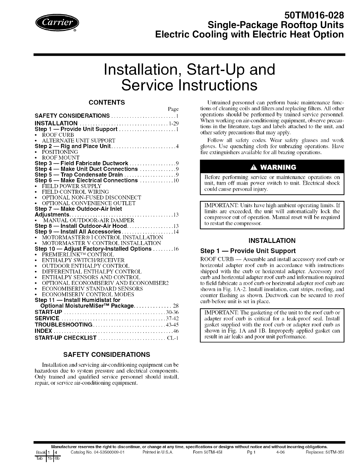
ROOF CURB -- Asselnble and install accessory roof curb or
horizontal a&tpter roof curb in accordance with instructions
shipped with the curb or horizontal adapter Accessory roof
curb and horizontal adapter roof curb and information required
to field fabricate a roof curb or horizontal adapter roof curb are
shown in Fig. IA-2. Install insulation, cant strips, roofing, and
counter flashing as shown. Ductwork can be secured to roof
curb before unit is set in place.
IMPORTANT: The gasketing of the unit to the roof curb or
adapter roof curb is critical for a leak-proof seal. Install
gasket supplied with the roof curb or adapter roof curb as
shown in Fig. IA and lB. hnpropefly applied gasket can
result in air leaks and poor unit performance.
SAFETY CONSIDERATIONS
Installation and servicing air-conditioning equipment can be
hazardous due to system pressure and electrical components.
Only trained and qualified service personnel should install,
repair, or service air-conditioning equipment.
Manufacturer reserves the right to discontinue, or change at any time, specifications or designs without notice and without incurring obligations.
Catalog No. 04-53500009-01 Printed in U.S.A, Form 5OTM-4SI Pg 1 4-06 Replaces: 50TM-3SI
_K o _EF sc_ _I ON
_1 !kbi
CR7 CU/BO!OAO0 2 - STANDARD14.HIGHCURB
{305}
c,_rr ,so AO 2 o uNf '_ECX'/N
o0, I'G INBTDL L DTION
C bgB('zO_ 2{" _r _.....
". ",/ lIE IU _N vkl/b
[s o, J C INS All ATIOq
E" 2 3/ 6"
(i885) i
(REF SUPPLY OPEhiNG) _
A
A
G'I/4 _ _ _ i
5/.i/2"" PLA\ V[EW 01: ROOf: CURB
Z7!7 _ .... T *,, o cN
J
S i>P v RE RN i '
(0' :_ .... i
*JE CURB
75)
' I
................. ] ................ i
NOTE =
i. ROOF CUR[ ACC[ _,SOR' ]5 71[>P[D D[S_ [f_{_LED.
P. INSULATED PDNELS_ I _ THICK NEOPRENE COATED i¸¸I/2 LB DENSITY
3. I}IMFNS[ONS IN ( } ARE /N _1ill ]HETERS.
4 c::_ {}IRE(}I {Of,, OF AiR iLOt_
5. ROOFCURB_ /6 GA. (VA03 $6) 91L.
B. A 90 DEGREE ELBOW MUST BE INSTALLED ON THE SUPPLY DUCT
WORK BELOW THE UNIT OIBCHARBE FOR UNITB EQUIPPED WITH ,
ELECTRIC HEATERS.
\OE:
T) PR:V{ \T I{ I#ZAR} "c_ :r "N N i/*r *......
BULB UP IN E DR/,IN PAN O IE NDOOR
;C ON, ,,q T CAI 0/v B[ 1TCqE{) #5 WtOWii.
, ..................... {
i ONOTN{ ER J
ANO i
i COM RFS{ (}R i
i
]....... 7
/
3 I'IENI]ONS (degree or/d rchet}
($I}
NOH. /4<" X 4 _ \
(32) X (102) \_
IYP< /- P_C9
O" i
(44)
(310) (_78)
3/4" ,NSULA[{ PAN[L :OR !I[}E
/UPPIY AND RETLRN
(CRRFCUR_O12AO0 ONLY)
/ I/4 ° I
TABI E
....O" 3"
(76)
Ub, l l {7\E{ iNG 0 _AI °'c :'
• -o,i odg of mnf Lo *_),- o,'toL,
GASKET
(SUPPL {£O ]Tk CURB)
OUOT ......
FIELO SUI>I>I /E} (IANJ $i_1 )
/
!(F ! E_9 SUPPL ] ED)
R]GD NSUL AT[ON
(FEID SLRPL B)
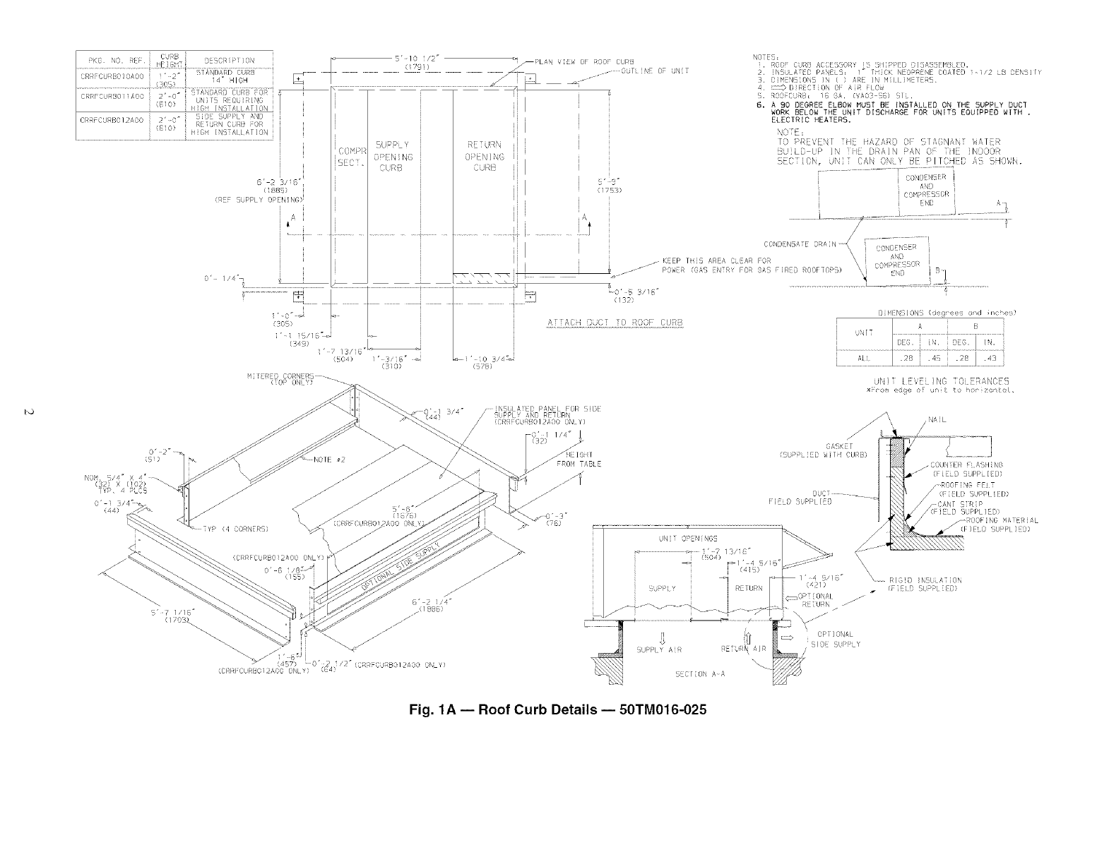
Fig. 1A iRoof Curb Details i50TM016-025
,..,J
ROOFCURB I CURB I DESCRIPTION i
ACCESSORY IHEIGHT] d
ROD,co,o]CR,,CUROO AO01,"HIOH __._ ,, m
a_i,
I
13/ _,,i
_<3;D:
i5 1/16 i
i
I
(226_)
i L3/161
i (31o):
I
KEP ] S AREA CLEAR I))R I
(GAS NTRY FOR GAS IRFD F
NOTES:
1, RGOFCURB ACCESSORY IS SHIPPES OISASSEMBLED.
2. SIWENSIONS IN (I ARE IN NILLIWETENS.
..........F'--I
2 1/41_ I
(886} i
!IN RF SUPPLY OR NIRB _
ii -
ii •
I
INSULA- ED _ANE
/
_Ui_pLV OP N_'[x,G C Ui_B ii l
INSULATED PANEL
I
tRE IURN OPENI G
i
IiCURB
I
(132/
1O"
DIMENSIONS {DEGREES AND INCHES1
A B
UNIT DEC. IN. DEC. IN.
ALL .28 .45 .28 .43
MAX CURB LEVELING TOLERANCES:
FROM EDGE OF UNIT TO HORIZONTAL
f
1 7 i3/6"
(504)
I
: ii_D79}
PLAN VIEW OF ROOR CUR8
:_--OUTLiN[ OF UNIT
CON_ RSATE DRAN
8J
3. [_DIRECTION OF AIRFLOW,
4, ROOF CURS: IS SA, (VAO3-5S} STEEL.
5. TO PREVENT THE HAZARD OF STAGNANT WATER BUILD-UP IN THE DRAIN PAN
OF THE INOOOR SECTION. UNIT CAN ONLY BE PITCHES AS SHOWN,
6. INSULATED PANELS: T" THICN NEOPRENE COATED I-T/2 LB DENSITY.
7, A9_ ELBOW MUST BE INSTALLED ON THE SUPPLY DUCT WORE BELOW
THE UNIT DISCHARGE FOR UNITS [OUIPPES WITH ELECTRIC HEATERS,
TOP ONLY
_ D
i
i 7 51/!0"
L
LNOM S/4': X 4: TYP 4 PLACES
_EIBHI FROM TABLE
ATTACH DUCT WORK T i JRTTS (SUPPLIED WITH
COUNTER FLASH( NS
(FIELD SUPPLIEOI
NOOF I NG FELT
SUPP Dt]C_T-LIEU (FIELD SUPPLIED)
FIELD CANT STRIP
(PIELO SUPPLIED}
----_\ " _ IELD SUPPLIESI
12 F_'"T'S'u" _ _ ........150'1) F(';I'IS 5/18'
(4419/18' L RIGID INSULATION
SUPPLY RETURN _' (FIELD SUPPLIES)
_OPT ]ONAL
RETURN
j,,,:
su,;
£a_ SECTION A'A _!/J
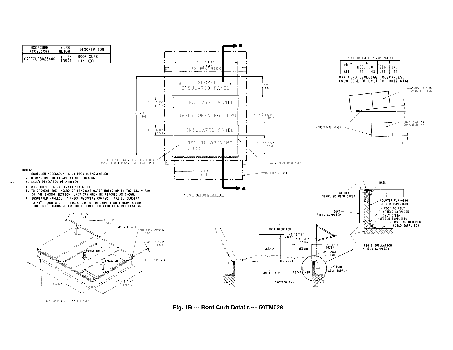
Fig. 1B -- Roof Curb Details -- 50TM028
25% VENT AIR/ /
ECONOMIZER --_/
HOOD _._
BLOCK-OFFAl__ l
PAN
HORIZONTAL SUPPI
I
i
Y" TRANSITION DUCT
CURB (CRRFCURB013A00)
14-3/4"
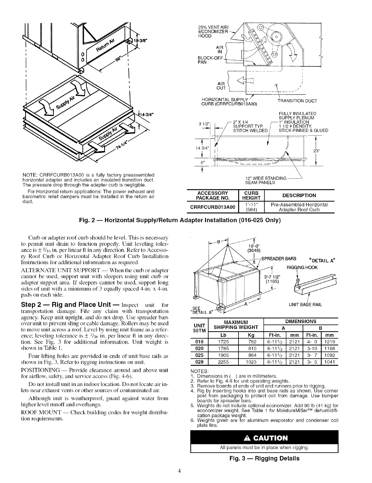
NOTE: CRRFCURB013A00 is a fully factory preassembled
horizontal adapter and includes an insulated transition duct,
The pressure drop through the adapter curb is negligible,
For Horizontal return applications: The power exhaust and
barometric relief dampers must be installed in the return air
duct,
FULLY INSULATED
SUPPLY PLENUM
31_ _ _ 2"uXI'_R T TYP. /_ I"ll/NSUDLEATIsITNy,
I ] /STITCH WELDED/STICK PINNED & GLUED
143/4"1 i 23
12" WIDE STANDING
SEAM PANELS
ACCESSORY CURB DESCRIPTION
PACKAGE NO. HEIGHT
1'-11" Pre-Assembled Horizontal
CRRFCURB013A00 (584) Adapter Roof Curb
Fig. 2 -- Horizontal Supply/Return Adapter Installation (016-025 Only)
Curb or adapter roof curb should be level. This is necessary
to permit unit &'ain to function properly. Unit leveling toler-
ance is + 1/16 in. per linear ft in any direction. Refer to Accesso-
ry Roof Curb or Horizont_d Adapter Roof Curb Installation
Instructions for additional information as required. /
ALTERNATE UNIT SUPPORT -- When the curb or adapter .__
cannot be used, support unit with sleepers using unit curb or
adapter support area. If sleepers cannot be used, support long
sides of unit with a minimum of 3 equally spaced 4-in. x 4-in.
pads on each side.
Step 2 -- Rig and Place Unit--Inspect unit for SEE
transportation &mmge. File any chfim with transpom_tion DETAILA"
agency. Keep unit upright, and do not drop. Use spleader bm_
over unit to prevent sling or cable damage. Rollers may be used UNIT
to move unit across a roof. Level by using unit frmne as a refer- 50TM
ence; leveling tolerance is + I/v, in. per line;u ft in any direc-
tion. See Fig. 3 for additional information. Unit weight is
shown in Table 1.
Four lifting holes am provided in ends of unit base rails as
shown in Fig. 3. Refer to rigging instructions on unit.
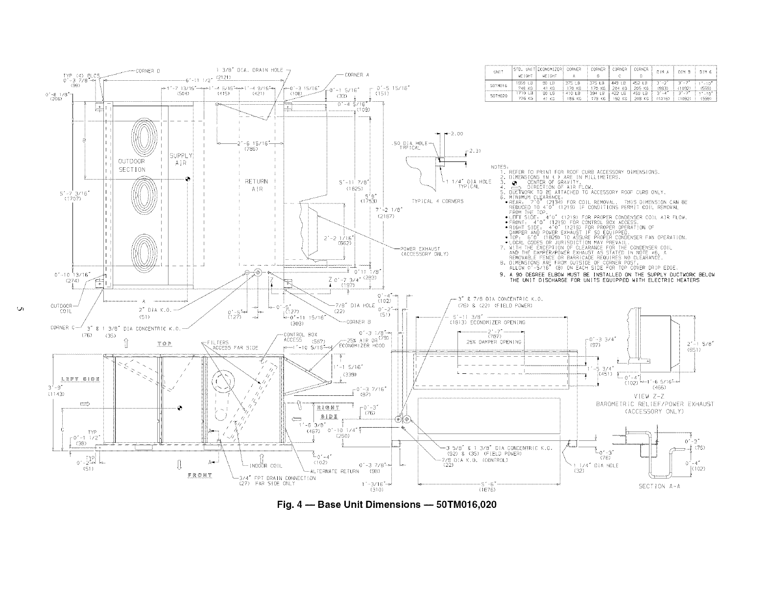
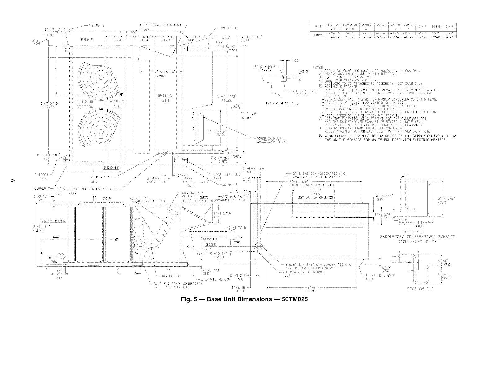
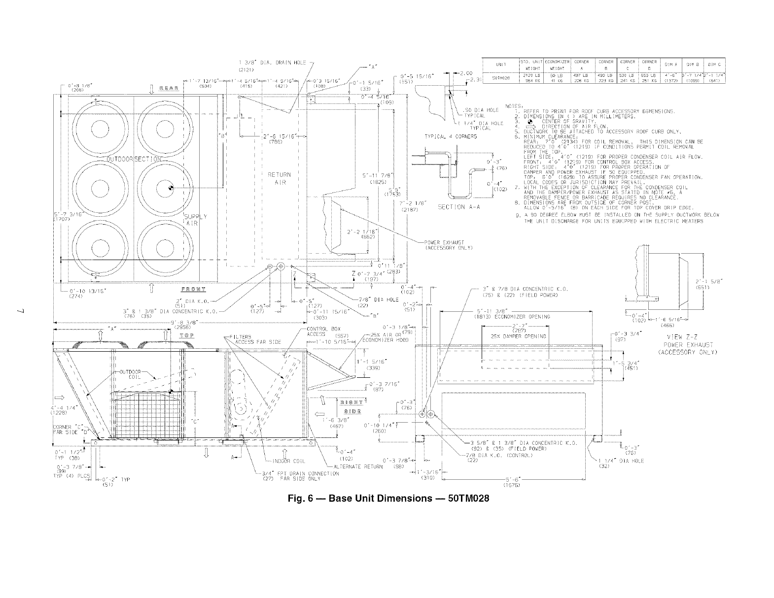
POSITIONING -- Provide clearance around and above unit
for airflow, safety, and service access (Fig. 4-6).
Do not insUdl unit in an indoor location. Do not locate air in-
lets near exhaust vents or other sources of contaminated _fil:
Although unit is weatherproof, guard against water from
higher level runoff and overhangs.
ROOF MOUNT -- Check building codes for weight distribu-
tion requirements.
10'-0"
(3048)
,SPREADER BARS "DETAIL A"
RIGGING HOOK
3'-7 1/2"
(t to51
UNIT BASE RAIL
016
020
025
028
NOTES:
1. Dimensions in (
MAXIMUM
SHIPPING WEIGHT
Lb Kg
1725 782
1785 810
1905 864
2255 1023
DIMENSIONS
A B
Ft-in. mm R-in. mm
6-111_ 2121 4- 0 1219
6-111_ 2121 3-10 1168
6-111_ 2121 3- 7 1092
6-111_ 2121 3- 5 1041
) are in millimeters,
2. Refer to Fig. 4-6 for unit operating weights.
3. Remove boards at ends of unit and runners prior to rigging.
4. Rig by inserting hooks into unit base rails as shown. Use corner
post from packaging to protect coil from damage. Use bumper
boards for spreader bars.
5. Weights do not include optional economizer. Add 90 Ib (41 kg) for
economizer weight. See Table 1 for MoistureMi$er TM dehumidifi-
cation package weight.
6. Weights given are for aluminum evaporator and condenser coil
plate fins.
All panels must be in place when rigging.
Fig. 3-- Rigging Details
{274}
J/
/
0UTDGOR /_ I} DK.0.
COIL /
/s1_ J
(' NI:R C /-"
...... g 3/8" { A COND NTR C K0/
((} (3!
::ss _f
G' 4_
9. A 90 DEGREE ELBOW MUST BE INSTALLED ON THE SUPPLY DUCTWORK BELOW
THE UNIT DISCHARGE FOR UNITS EOUIPPEO WITH ELECTRIC HEATERS
/3__7/8 ©]_\ D©NCENTR}C _.O.
{5/)
'_3/4 _ £PT DRA]N CONNECTION
{27) FAR SiDE @4i Y
(3_0} (1676)
Fig. 4 -- Base Unit Dimensions i50TM016,020
S CT] ON A a
_B
Fig. 5 JBase Unit Dimensions J50TM025
-q
i/{ _ ){D- i)RA/\ iI0 uJ ...... /CON .......... ....... I .... ..... ] 'M _ / O _ J C i
<P21' / / "Am i L,E_GHr / _,E_G,:T [ A i _ I C i C i .......... / i
(2O,
i i .... _-_j i ..... ........ | _ :\ j ',, _ .50 i) A I01{ 1 R f i P S 0 R : RB AC RY S N [ N
J ] i | "_ YPCA[ 2 DISEN510 9 F. ( ) ArCE N H LL IETER8.
, _ .... ;//d ,,/, p>
].. , i " 5 DC _ORK ]0 8E /rTt_C ED ]0 DCCE5807_ _OOf CURS ONL ,
_. _ B _2' 6 IS/SB%q IICAL 4 COINE45 6 bllN MUhl C ESbtNOE
(788 , i REAR 70" (21 ]4) FOR C)i R MO'_A F 0 HEN N }AN B
_ _ RIDUCi ) 0 4"0" (129) COND J ONE Pqb I COil bO_AI
i .....................1 _ IP,O EOR.i _ Y LET SIDE: 4"0 _ (i219} FOR PROPER CONDEN5 R CO}L A{A FLOI,.
i _ i 0"7 FRONT: 4"0" (1219) OR CONTRO BOX 4CCESS,
i _ ._ _76 RC'C" 2 ) :0_ PROPER O)RZ_ ON OF
AETUY_N i I (" _ {sSM)E AN _ )OWE EXHAUST IF 50 OU P)ED,
5- e L_ j / o> 8,o ° (189) io ASS /E >RO>R CON) NSER FAh, O>ERAI ON
O" 4 _ LOCAl CO{)S 0 J; !)C /8N SAY PR[_A ,
| - 59" | | /(1C2 ,x M!ll lie EXC PT ON OF C ARANC [0 q CON[)[ £{R COl
[ &N) H{ [}A,NRiR/R()W[IR EXiqAU AS $ AIEi) IN NOI _B, A
: _ .....,/<3 <q _-
s2REIO/ABLE FENCE OR BARR CDDE RE© AEE NO CLEARANCE
J _ I j ' 2 //8' • m s 8 DISENS]ON5 4RE FROb 0 TS]DE OF CORI, ER :_05 ,
,,,,,,, . . /,L OW 0' 5/ I/ (!) Oq ELCi /[): OR 0 CO_ER ID8 .
707) LV i l k ,_"-_ l l (2182) :! CT O_ ,- A 9. & 0 i)EGR [ BO_ bIU i i qfl_\ LI! )N /l[ XJi> DUO/WORK 8 (X,
IH[ N I I)[ ItAA([ FOR UN l! QLJIPP[I) ,, ['E( R}( [A/ R
X 2' 2 /)8"1 _-L
, i i 862) i "_.
l i l ""iPO_ ER EX A8 T
\_ i o',/c, _Rv w
i ...... ...... i
0'1 1/8"
Z O' 7_/4: {:} { /
l (i97 ' /8"
n' . , -F_B@_Y C""_ 3" 7/8 )]A CONCENTRIC KO, (/}
1 3,1o _ (02, /",
/' (78) 8 ( ) (iE{)>OWE_)
.2/4) " l} A K.O _ _" O" S" _7/8 _ DIA IOLE ,.- .....
( ) 0<s_d ;_ (2) _ (2) 0
3" 8 sis" ." :, CO,,C:N< c _ o /(1 _3 ,_ _,o" /_ sl ] _,, . :,8 o _ ;'
{2() (3) i : 0 _) "3" ! ,/' 1 ] ) OONOMIZER 0 N NO L 0"£4 /B ---
........................................................................................................................... -: ........................... _r)'( {}8 /8: ........................................................................................... ...._CON[ _0.... X 0" 17 ; /{ _ } // •/' 7" *'1 /i (471[g)
T-/s _ .v78 1 i{///' ./ (,_{7) 1 " .... 4"
@_ I ir R /c.c ..... .:.7 2, ,_ R . // 5_. O/t_PER OPENING i1 'i_3_ ' ".'ZEta, Z Z
"/\ c:_'5 Dr 5"IO 8/IS _/cO0+iZER oo) i i
.......... /, {,, , Or,, E _ [ XIiAU
_, /i F:;;..................................... ] ..................:ff , 4 l (_ C SSORYONY)
,/ h" /17" I/......................................................................... i 1" { :_/4 _
i (3:87
©" 8 7/1_" ///i ............................................................................] -;i 71
4"41/4
(228)
X)RNER "0" ,
FAR SIDE °9"
.... [N{)OOR 0011 (I02) O" 3 ?/8:'_ _- (22) _1 i/4 _ Olt_ OLi
O" • '8" _ t
(99) ', --AL RNA E RE U2\ (_}) (2)
T'_ (4) _LC5 ' 2" TYP " 3/4 _ )RAIN CONNIC ON •"/6"_
:; (27) FAR 91) ONY (310 L_ 5' 6
(S]) (1 78)
Fig. 6 iBase Unit Dimensions i50TM028
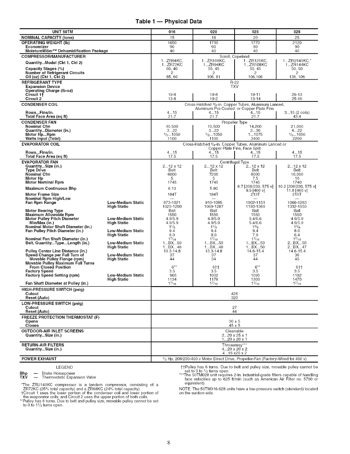
Table1 -- Physical Data
UNIT 50TM 016 020 025 028
NOMINAL CAPACITY (tone) 15 16 20 25
OPERATING WEIGHT (Ib) 1650 1710 1770 2120
Economizer 90 90 90 90
MoistureMi$er TM Dehumidification Package 40 40 40 40
COMPRESSOR/MANUFACTURER Scroll, Copeland
Quantity..,Model (Ckt 1, Ckt 2) 1_.ZR94KC, 1...ZRIOSKC, I 1._ZR125KC, 1_.ZRU140KC,*
1..,ZR72KC 1,_ZR94KC 1._ZR108KC 1_.ZR144KC
Capacity Stages (%) 60, 40 55, 45 I 55, 45 50, 50
Number of Refrigerant Circuits 2 2 2 2
Oil (oz) (Ckt 1, Ckt 2) 85, 60 106, 81 106,106 136, 106
REFRIGERANT TYPE R-22
Expansion Device TXV
Operating Charge (Ib-oz)
c,rcuittt 19-6 I 19-6 I 18-11I 26-13Circuit 2 13-8 19-2 13-14 25-10
CONDENSER COIL Cross-Hatched 3/8-in. Copper Tubes, Aluminum Lanced,
Aluminum Pre-Coated, or Copper Plate Fins
Rows,..Fins/in, 4...15 I 4_.15 I 4_.15 I 3_,15 (2 coils)
Total Face Area (sq ft) 21,7 21,7 21.7 43.4
CONDENSER FAN Propeller Type
Nominal Cfm 10,500 10,500 I 14,200 21,000
Quantity..,Diameter (in.) 3,.,22 3,..22 I 2.,.30 6.,,22
Motor Hp,.,Rpm V2_.1050 V2...1050 1,,,1075 V2...1050
Watts Input (Total) 1100 1100 3400 2200
EVAPORATOR COIL Cross-Hatched 3/8-in. Copper Tubes, Aluminum Lanced or
Copper Plate Fins, Face Split
4...15 I 4...15 I 4_.15 I 4._15
17.5 17,5 17.5 17,5
Centrifugal Type
2,,,12 x 12 2.,,12 x 12 2,.,12 x 12
Rows,..Finslin,
Total Face Area (sq ft)
EVAPORATOR FAN
Quantity...Size (in,)
Type Drive
Nominal Cfm
Motor Hp
Motor Nominal Rpm
Maximum Continuous Bhp
Motor Frame Size
Nominal Rpm High/Low
Fan Rpm Range Low-Medium Static
Belt
6000
5
1745
6.13
184T
873-1021
Belt
7200
5
1745
5.90
184T
910-1095
Belt
8000
7.5
1745
8.7 [208/230, 575 v]
9,5 [460 v]
213T
1002-1151
Motor Bearing Type
Maximum Allowable Rpm
Motor Pulley Pitch Diameter
Min/Max (in.)
Nominal Motor Shaft Diameter (in.)
Fan Pulley Pitch Diameter (in.)
Nominal Fan Shaft Diameter (in.)
Belt, Quantity..,Type...Length (in,)
Pulley Center Line Distance (in,)
Speed Change per Full Turn of
Movable Pulley Flange (rpm)
Movable Pulley Maximum Full Turns
From Closed Position
Factory Speed
Factory Speed Setting (rpm)
High Static
Low-Medium Static
High Static
Low-Medium Static
High Static
Low-Medium Static
High Static
Low-Medium Static
High Static
Low-Medium Static
High Static
1025-1200
Ball
1550
4.9/5,9
4.9/5,9
1_&
9,4
8,0
17/16
1,,,BX...50
1,,,BX...48
13.3-14.8
37
44
6**
3,5
965
1134
17/16
1069-1287
Ball
1550
4,9/5.9
4,9/5.9
11/8
9.4
8.0
17/16
1..,BX,..50
1._BX,.,48
13.3-14.8
37
34
6tt
3.5
1002
1178
17/16
1193-1369
Ball
1550
5.4/6.6
5.4/6.6
13/8
9.4
7.9
17/16
1._BX_.53
1_.BX._50
14.6-15.4
37
44
6**
3.5
1095
1303
17/16
2,.,12 x 12
Belt
10,000
10
1740
10.2 [208/230, 575 v]
11,8 [460 v]
215T
1066-1283
1332-1550
Ball
1550
4.9/5,9
4.9/5,9
13/8
8,0
6.4
17/16
2,..BX-,50
2,.,BX-,47
14.6-15,4
36
45
6tt
3.5
1182
1470
17/16
Fan Shaft Diameter at Pulley (in.)
HIGH-PRESSURE SWITCH (psig)
Cutout 426
Reset (Auto) 320
LOW-PRESSURE SWITCH (psig)
Cutout 27
Reset (Auto) 44
FREEZE PROTECTION THERMOSTAT (F)
Opens 30 _+5
Closes 45 _+5
OUTDOOR-AIR INLET SCREENS Cleanable
Quantity,.,Size (in,) 2...20 x 25 x 1
1,,.20 x 20 x 1
RETURN-AIR FILTERS Throwaway***
Quantity,..Size (in.) 4.,.20 x 20 x 2
4._16 x20 x2
POWER EXHAUST V2 Hp, 208/230-460 v Motor Direct Drive, Propeller-Fan (Factory-Wired for 460 v)
LEGEND
Bhp -- Brake Horsepower
TXV -- Thermostatic Expansion Valve
*The ZRU140KC compressor is a tandem compressor, consisting of a
ZR72KC (25% total capacity) and a ZR68KC (24% total capacity),
tCircuit 1 uses the lower portion of the condenser coil and lower portion of
the evaporator coils; and Circuit 2 uses the upper portion of both coils,
**Pulley has 6 turns. Due to belt and pulley size, movable pulley cannot be set
to 0 to 11/2turns open,
tl-Pulley has 6 turns. Due to belt and pulley size, movable pulley cannot be
set to 0 to V2 turns open,
***The 50TM028 unit requires 2-in, industrial-grade filters capable of handling
face velocities up to 625 ft/min (such as American Air Filter no. 5700 or
equivalent).
NOTE: The 50TM016-028 units have a low-pressure switch (standard) located
on the suction side.
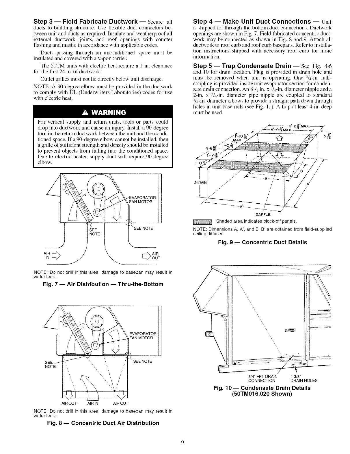
Step 3 -- Field Fabricate Ductwork -- Secure all
ducts to building structure. Use flexible duct connectors be-
tween unit and ducts as required. Insulate and weatherproof all
external ductwork, joints, and roof openings with counter
flashing and mastic in accordance with applicable codes.
Ducts passing through an unconditioned space must be
insulated and covered with a vapor barriel:
The 50TM units with electric heat require a l-in. clearance
for the first 24 in. of ductwork.
Outlet grilles must not lie directly below unit disch_u'ge.
NOTE: A 90-degree elbow must be provided in the ductwork
to comply with UL (Underwriters Laboratories) codes for use
with electric heat.
For vertical supply and leturn units, tools or pmls could
diop into ductwork and cause an injury. Inst_dl a 90-degree
turn in the return ductwork between the unit and the condi-
tioned space. If a 90-degree elbow cannot be installed, then
a grille of sufficient strength and density should be installed
to prevent objects from falling into the conditioned space.
Due to electric heatel: supply duct will require 90-degree
elbow.
EVAPORATOR-
FAN MOTOR
NOTE
LV! OUT
NOTE: Do notdrillinthisarea;damage tobasepanmay resultin
water leak.
Fig. 7 -- Air Distribution -- Thru-the-Bottom
NOTE
AIR OUT AIR IN AIR OUT
NOTE: Do not drill in this area; damage to basepan may result in
water leak.
Fig. 8-- Concentric Duct Air Distribution
Step 4 -- Make Unit Duct Connections -- Unit
is shipped for through-the-bottom duct connections. Ductwork
openings tue shown in Fig. 7. Field-fabricated concentric duct-
work may be connected as shown in Fig. 8 and 9. Attach all
ductwork to roof curb and roof curb basepans. Refer to installa-
tion instructions shipped with accessory roof curb for mole
information.
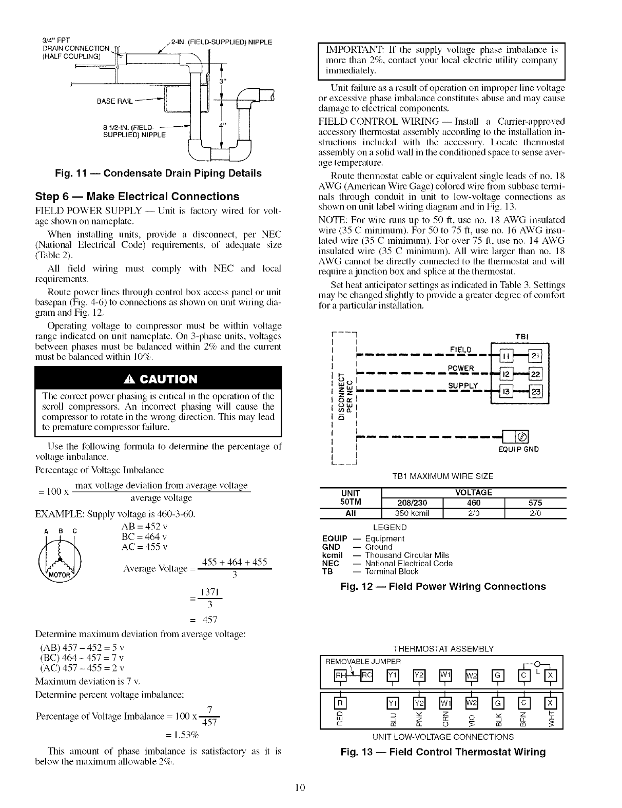
Step 5-- Trap Condensate Drain -- See Fig. 4-6
trod 10 for di'ain location. Plug is provided in drain hole and
must be removed when unit is operating. One :V4-in. half-
coupling is provided inside unit evaporator section for conden-
sate drain connection. An 81/2 in. x :V4-in. diameter nipple and a
2-in. x :V4-in. diameter pipe nipple are coupled to standard
3/4-in. diameter elbows to provide a straight path down through
holes in unit base rails (see Fig. 11). A trap at least 4-in. deep
must be used.
!
BAFFLE
Shaded area indicates block-off panels.
NOTE: Dimensions A, A', and B, B' are obtained from field-supplied
ceiling diffuser.
Fig. 9 -- Concentric Duct Details
\\\\
\\\
\\\\\\\
\\\\\
\\
3/4" FPT DRAIN 1-3/8"
CONNECTION DRAIN HOLES
Fig. 10- Condensate Drain Details
(50TM016,020 Shown)
3/4" PPT /2-IN, (FIELD-SUPPLIED)
DRAIN CONNECTION /
/HALF ]_
,e 3"
BASE RAIL _-__._
81/2-1N. (FIELD- _---'=
SUPPLIED) NIPPLE
NIPPLE
Fig. 11 -- Condensate Drain Piping Details
Step 6-- Make Electrical Connections
FIELD POWER SUPPLY -- Unit is factory wired for volt-
age shown on nameplate.
When installing units, provide a disconnect, per NEC
(National Electrical Code) requirements, of adequate size
(Table 2).
All field wMng must comply with NEC and loc:d
requirements.
Route power lines through control box access panel or unit
basepan (Fig. 4-6) to connections as shown on unit wiring dia-
gram and Fig. 12.
Operating voltage to compressor must be within voltage
range indicated on unit nmneplate. On 3-phase units, voltages
between phases must be balanced within 2% and the current
must be b_danced within 10%.
The correct power phasing is critical in the operation of the
scroll compressors. An incorrect phasing will cause the
compressor to rotate in the wrong direction. This may lead
to plemature complessor failure.
Use the following formula to determine the percentage of
voltage imbalance.
Percentage of Voltage Imbalance
= 100 x max voltage deviation fiom average voltage
average voltage
EXAMPLE: Supply voltage is 460-3-60.
AB = 452 v
AB C
BC = 464 v
AC = 455 v
Average Voltage = 455 + 464 + 455
3
1371
3
= 457
Determine maximum deviation from average voltage:
(AB) 457 - 452 = 5 v
(BC) 464 - 457 = 7 v
(AC) 457 - 455 = 2 v
Maximum deviation is 7 v.
Determine percent voltage imbalance:
Percentage of Voltage [mbalance = 100 x- 7
457
= 1.53%
This amount of phase imbalance is satisfacto Uas it is
below the maximum allowable 2%.
IMPORTANT: If the supply voltage phase imbalance is
more than 2%, contact your local electric utility company
immediately.
Unit failure as a result of operation on improper line voltage
or excessive phase imbalance constitutes abuse and may cause
damage to electrical components.
FIELD CONTROL WIRING -- Install a Carrier-approved
accessory thermostat assembly according to the installation in-
structions included with the accessory. Locate thermostat
assembly on a solid wall in the conditioned space to sense aver-
age temperature.
Route thermostat cable or equiwdent single leads of no. 18
AWG (American Wire Gage) colored wire from subbase temri-
nals through conduit in unit to low-voltage connections as
shown on unit label wiring diagram and in Fig. 13.
NOTE: For wire runs up to 50 It, use no. 18 AWG insulated
wire (35 Cminimum). For 50 to 75 fi, use no. 16 AWG insu-
lated wire (35 Cminimum). For over 75 It, use no. 14 AWG
insulated wire (35 C minimum). All wire lmger than no. 18
AWG cannot be directly connected to the thermostat and will
require a junction box and splice at the thermostat.
Set heat anticipator settings as indicated in Table 3. Settings
may be changed slightly to provide a greater degree of comfort
for a particular inst_dlation.
----] TBt
I
b
w_
zW
z z
o_
ow
o3o.
EQUIP GND
TB1 MAXIMUM WIRE SIZE
UNIT
50TM 208/230 IAll 350 kcmil
LEGEND
EQUIP -- Equipment
GND -- Ground
kcmil -- Thousand Circular Mils
NEC -- National Electrical Code
TB -- Terminal Block
VOLTAGE
460 575
2/0 2/0
Fig. 12- Field Power Wiring Connections
THERMOSTAT ASSEMBLY
JUMPER I
Cl _ Z Z 7-
cc m a_ O _ m m
UNIT LOW-VOLTAGE CONNECTIONS
Fig. 13 -- Field Control Thermostat Wiring
10
UNIT
50TM
016
020
025
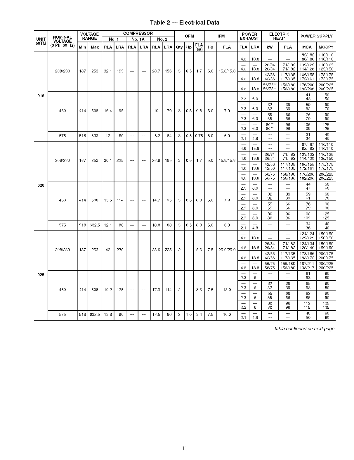
Table 2 -- Electrical Data
VOLTAGE COMPRESSOR OFM IFM
NOMINAL RANGE No, 1 No. 1A No. 2
VOLTAGE FLA
(3 Ph, 60 Hz) Min Max RLA LRA RLA LRA RLA LRA Qty Hp (ea) Hp FLA
208/230 187 253 32.1 195 20.7 156 3 0.5 1.7 5.0 15.8/15.8
460 414 508 16.4 95 10 70 3 0.5 0.8 5.0 7.9
575 518 633 12 80 8.2 54 3 0.5 0.75 5.0 6.0
208/230 187 253 30.1 225 28.8 195 3 0.5 1.7 5.0 15.8/15.8
460 414 508 15.5 114 14.7 95 3 0.8 0.8 5.0 7.9
575 518 632.5 12.1 80 10.8 80 3 0.5 0.8 5.0 6.0
208/230 187 253 42 239 33.6 225 2 1 6.6 7.5 25.0/25.0
460 414 508 19.2 125 17.3 114 2 1 3.3 7.5 13.0
575 518 632.5 13.8 80 13.5 80 2 1.0 3.4 7.5 10.0
POWER ELECTRIC POWER SUPPLY
EXHAUST HEAT*
FLA LRA kW FLA MCA MOCPt
-- 82/ 82 110/110
4.6 18.8 -- -- 86/ 86 110/110
26/34 71/ 82 109/122 110/128
4.6 18.8 26/34 71/ 82 114/128 125/180
42/56 117/135 166/155 175/175
4.6 18.8 42/56 117/135 172/161 178/175
56/75"* 156/180 176/200 200/225
4.6 18.8 56/75"* 156/180 182/206 200/225
-- 41 50
2.3 6.0 -- -- 43 50
32 39 59 60
2.3 6.0 32 39 62 70
55 66 76 90
2.3 6.0 55 66 79 90
80** 96 106 125
2.3 6.0 80** 96 109 125
-- 31 40
2.1 4.8 -- -- 34 40
-- 87/ 87 110/110
4.6 18.8 -- -- 92/ 92 110/110
26/34 71/ 82 109/122 110/125
4.6 18.8 26/34 71/ 82 114/128 125/150
42/56 117/135 166/155 175/175
4.6 18.8 42/56 117/135 172/161 175/175
56/75 156/180 176/200 200/225
4.6 18.8 56/75 156/180 182/206 200/225
-- 44 50
2.3 6.0 -- -- 47 60
32 39 59 60
2.3 6.0 32 39 61 70
55 66 76 90
2.3 6.0 55 66 79 90
80 96 106 125
2.3 6.0 80 96 109 125
-- 34 40
2.1 4.8 -- -- 36 40
-- 124/124 150/150
4.6 18.8 -- -- 129/129 150/150
26/34 71/ 82 124/134 150/150
4.6 18.8 26/34 71/ 82 129/140 180/150
42/56 117/135 178/166 200/175
4.6 18.8 42/56 117/135 183/172 200/175
56/75 156/180 187/211 200/228
4.6 18.8 56/75 156/180 193/217 200/225
-- 61 80
2.3 6 -- -- 63 80
32 39 65 80
2.3 6 32 39 68 80
55 66 82 90
2.3 6 55 66 85 90
80 96 112 125
2.3 6 80 96 115 125
-- 48 60
2.1 4.8 -- -- 50 60
Tab_confinued on next page.
1!
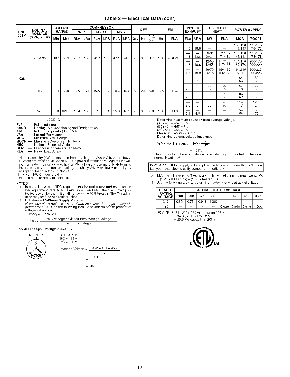
Table 2 -- Electrical Data (cont)
UNIT NOMINAL
50TM VOLTAGE
(3 Ph, 60 Hz)
208/230
028
46O
578
VOLTAGE COMPRESSOR OFM
RANGE No. I No, 1A No, 2
FLA
Min Max RLA LRA RLA LRA RLA LRA Qty Hp (ea)
187 253 20.7 156 20.7 156 47.1 245 6 0.5 1.7
IFM
Hp FLA
10.0 28.0/28.0
POWER ELECTRIC
EXHAUST HEAT*
FLA LRA kW FLA
4.6 18.8 -- --
26/34 71/ 82
4.6 18.8 26/34 71/ 82
42/56 117/135
4.6 18.8 42/56 117/135
56/75 156/180
4.6 18.8 56/75 186/180
POWER SUPPLY
MCA MOCPt
138/138 178/178
143/143 175/178
138/188 178/178
143/143 178/178
181/170 200/175
187/176 200/200
191/215 200/225
197/221 200/225
414 508 10.0 75 10.0 75 19.6 125 6 0.5 0.8
518 622.5 16.4 108 8.2 54 15.8 100 6 0.5 0.8
10.0 14.6
10,0 13,0
2.3 6 -- --
32 39
2.3 6 32 39
55 66
2.3 6 55 66
80 96
2.3 6 80 96
2.1 4.8 -- --
64 8O
66 80
67 80
70 80
84 90
87 100
114 125
117 125
54 60
56 70
LEGEND
FLA -- Full Load Amps
HACR -- Heating, Air Conditioning and Refrigeration
IFM -- Indoor (Evaporator) Fan Motor
LRA -- Locked Rotor Amps
MCA -- MinimumCircuitAmps
MOCP -- Maximum Overcurrent Protection
NEC -- National Electrical Code
OFM -- Outdoor (Condenser) Fan Motor
RLA -- Rated Load Amps
*Heater capacity (kW) is based on heater voltage of 208 v, 240 v and 480 v.
Heaters are rated at 240 v and 480 v. If power distribution voltage to unit var-
ies from rated heater voltage, heater kW will vary accordingly. To determine
heater capacity at actual unit voltage, multiply 240 v or 480 v capacity by
multipliers found in table in Note 4.
tFuse or HACR circuit breaker.
**Electric heaters are field installed.
NOTES:
1. In compliance with NEC requirements for multimotor and combination
load equipment (refer to NEC Articles 430 and 440), the overcurrent pro-
tective device for the unit shall be fuse or HACR breaker. The Canadian
units may be fuse or circuit breaker.
2. Unbalanced 3-Phase Supply Voltage
Never operate a motor where a phase imbalance in supply voltage is
greater than 2%. Use the following formula to determine the percent of
voltage imbalance,
% Voltage Imbalance
= 100 x max voltage deviation from average voltage
average voltage
EXAMPLE: Supply voltage is 480-3-60.
A B C AB = 452 v
(_ BC = 464 v
AC = 455 v
Average Voltage = 452 + 464 + 455
3
1371
3
Determine maximum deviation from average voltage.
(AB) 487 -482 = 8 v
(BC) 464 -487 = 7 v
(AC) 487 -488 = 2 v
Maximum deviation is 7 v.
Determine percent voltage imbalance.
7
% Voltage Imbalance = 100 x 45_
= 1.53%
This amount of phase imbalance is satisfactory as it is below the maxi-
mum allowable 2%.
IMPORTANT: If the supply voltage phase imbalance is more than 2%, con-]
tact your oca e ectr cut ty company tamed ate y. J
3. MCA calculation for 50TM016-028 units with electric heaters over 50 kW
= (1.28 x IFM amps) + (1.00 x heater FLA).
4. Use the following table to determine heater capacity at actual voltage.
HEATER ACTUAL HEATER VOLTAGE
RATING
VOLTAGE 200 208 230 240 380 440 460 480
240 0.694 0.781 0.918 1.000
480 0.626 0.840 0.918 1.000
EXAMPLE: 34 kW (at 230 v) heater on 208 v
= 34.0 (.751 mult factor)
= 25.8 kW capacity at 208 v.
LIST_O
=487
12
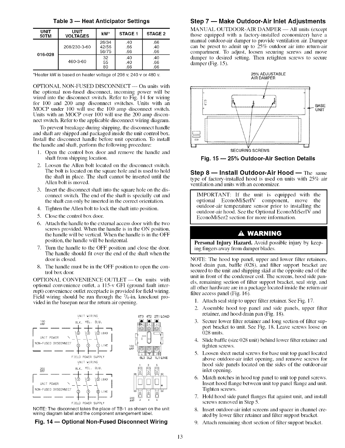
Table 3 -- Heat Anticipator Settings
UNIT
50TM
016-028
UNIT kW* STAGE 1
VOLTAGES
208/230-3-60
460-3-60
26/34 .40
42/56 .66
56/75 .66
32 .40
55 .40
80 .66
STAGE 2
.66
.40
.66
.40
.66
.66
*Heater kW is based on heater voltage of 208 v, 240 v or 480 v.
OPTIONAL NON-FUSED DISCONNECT -- On units with
the optional non-fused disconnect, incoming power will be
wired into the disconnect switch. Refer to Fig. 14 for wiling
for 100 and 200 amp disconnect switches. Units with an
MOCP under 100 will use file 100 amp disconnect switch.
Units with an MOCP over 100 will use the 200 amp discon-
nect switch. Refer to the applicable disconnect wiring diagrmn.
To prevent breakage during shipping, file disconnect handle
and shaft are shipped and packaged inside the unit control box.
Install file disconnect handle before unit operation. To install
the handle and shaft, perform the following procedure:
1. Open the control box door and remove the handle and
shaft fi'om shipping location.
2. Loosen the Allen bolt located on the disconnect switch.
The bolt is located on the square hole and is used to hold
the shaft in place. The shaft cannot be inserted until the
Allen bolt is moved.
3. |nsert the disconnect shaft into the square hole on the dis-
connect switch. The end of the shaft is specially cut and
the shaft can only be inserted in the correct orientation.
4. Tighten the Allen bolt to lock the shaft into position.
5. Close the control box dool:
6. Attach the handle to the external access door with file two
screws provided. When the handle is in the ON position,
the handle will be vertical. When the handle is in the OFF
position, the handle will be horizontal.
7. Turn the handle to the OFF position and close the door.
The handle should fit over the end of the shaft when the
door is closed.
8. The handle must be in the OFF position to open the con-
trol box dool:
OPTIONAL CONVENIENCE OUTLET-- On units with
optional convenience outlet, a l15-v GFI (ground fault inter-
rupt) convenience outlet receptacle is provided for field wiring.
Field wiring should be run through the 7/8-in. knockout pro-
vided in the basepan near the return air opening.
UNIT WIRING
I00 BLK. YEL. BLU.
AMP
FIELD POWER SUPPLY
UNIT WIRING
6T3 4T2 2T1 LOAD
100_
AMP
5L3 3L2 1L1 LINE
200 BLK. YEL, BLU.
AMP
[ ONITPDWER,
I NON FUSED DISCONNECT
F]ELD POWER SUPPLY
NOTE: The disconnect takes the place of TB-1 as shown on the unit
wiring diagram label and the component arrangement label.
Fig. 14 -- Optional Non-Fused Disconnect Wiring
Step 7 -- Make Outdoor-Air Inlet Adjustments
MANUAL OUTDOOR-AIR DAMPER -- All units (except
fllose equipped with a factory-inst_dled economizer) have a
manual outdoor-air &lmper to provide ventilation tdl: Dmnper
can be preset to admit up to 25% outdoor air into return-air
compartment. To adjust, loosen securing screws and move
&tmper to desired setting. Then retighten screws to secure
&tmper (Fig. 15).
25% ADJUSTABLE
AIR DAMPER
J
BASE
UNIT
SECURING SCREWS
Fig. 15 -- 25% Outdoor-Air Section Details
Step 8 -- Install Outdoor-Air Hood -- The same
type of factory-installed hood is used on units with 25% air
ventilation and units with an economizel:
IMPORTANT: If the unit is equipped with the
optional EconoMiSerlV component, move the
outdoor-air temperature sensor prior to installing the
outdoor-air hood. See the Optional EconoMiSerIV and
EconoMiSer2 section for more information.
Personal Injury Hazard. Avoid possible injmN by keep-
ing fingers away [roln dmnper blades.
NOTE: The hood top panel, upper trod lower filter retainers,
hood diain pan, baffle (028), and tilter support bracket are
secured to the unit and shipping skid at the opposite end of the
unit in front of the condenser coil. The screens, hood side pan-
els, remaining section of filter support bracket, seal strip, and
_dl other hardwme are in a package located inside file return-air
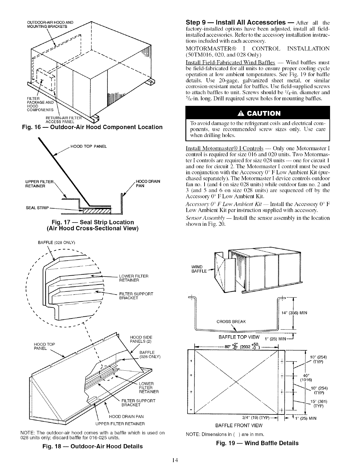
tilter access panel (Fig. 16).
1. Attach seal strip to upper filter retainel: See Fig. 17.
2. Assemble hood top panel and side panels, upper filter
retainer, and hood drain pan (Fig. 18).
3. Secure lower tilter retainer and long section of filter sup-
port bracket to unit. See Fig. 18. Leave screws loose on
028 units.
4. Slide baffle (size 028 unit) behind lower filter retainer and
tighten screws.
5. Ix_osen sheet metal screws for base unit top panel located
above outdoor-air inlet opening, and remove screws for
hood side panels located on the sides of the outdoor-air
inlet opening.
6. Match notches in hood top panel to unit top panel screws.
Insert hood thmge between unit top panel flange and unit.
Tighten screws.
7. Hold hood side panel flanges flat against unit, and install
screws removed in Step 5.
8. Insert outdoor-air inlet screens and spacer in channel cre-
ated by lower filter retainer and filter support bracket.
9. Attach remaining short section of filter support bracket.
13
OUTDOOR-AIR HOOD AND
MOUNTING BRACKETS
FILTER
PACKAGEANE
HOOD
COMPONENTS
ACCESS PANEL
Fig. 16- Outdoor-Air Hood Component Location
PANEL
UPPER FILTER.
RETAINER
HOOD DRAIN
Fig. 17 -- Seal Strip Location
(Air Hood Cross-Sectional View)
Step 9 -- Install All Accessories -- After ;dl the
factory-installed options have been adjusted, install all field-
inst_dled accessories. Refer to the accessory inst_dlation instruc-
tions included with each accessory.
MOTORMASTER® I CONTROL INSTALLATION
(50TM016, 020, and 028 Only)
Install Field-Fabricated Wind Baffles -- Wind baffles must
be field-fabricated for all units to ensure proper cooling cycle
operation at low ambient temperatures. See Fig. 19 for baffle
details. Use 20-gage, galvanized sheet metal, or similar
conosion-resistant metal for baffles. Use field-supplied screws
to attach baffles to unit. Screws should be 1/4-in. diameter and
5/8-in. long. Drill required screw holes for mounting baffles.
To avoid dmnage to the refiigelant coils and electric_d com-
ponents, use recommended screw sizes only. Use care
when drilling holes.
Install Motormaster® I Controls -- Only one Motormaster I
control is required for size 016 and 020 units. Two Motormas-
ter I controls tue required for size 028 units -- one for circuit 1
and one for circuit 2. The Motommster [ control must be used
in conjunction with the Accessory 0° F Ix_w Ambient Kit (pur-
chased separately). The Motormaster I device controls outdoor
fan no. 1 (and 4 on size 028 units) while outdoor fans no. 2 and
3 (and 5 and 6 on size 028 units) are sequenced off by the
Accessory 0° F Low Ambient Kit.
Accessom" 0 °F I_m' Ambient Kit -- Install the Accessory 0° F
Low AmiNent Kit per instruction supplied with accesso%
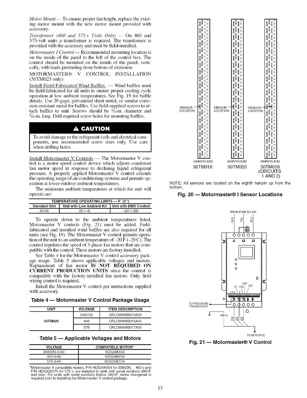
Sensor Assemb@ -- Install the sensor assembly in the location
shown in Fig. 20.
BAFFLE (028 ONLY)
j/t \
_ LOWER FILTER
//_4 RETAINER
I
FILTER SUPPORT
BRACKET
\/
\
\
\
HOOD TOP
PANEL
HOOD SIDE
PANELS (2)
BAFFLE
• LOWER
FILTER
RETAINER
FILTER SUPPORT
BRACKET
HOOD DRAIN PAN
UPPER FILTER RETAINER
NOTE: The outdoor-air hood comes with a baffle which is used on
028 units only; discard baffle for 016-025 units.
Fig. 18 -- Outdoor-Air Hood Details
WIND
BAFFLE __
i
___CROSS BREAK A
BAFFLETOP VIEW 1"(25)MIN---jl
_ 80"+2" ,_^ +50
-0" _z_z-0 )
÷*+-I--
3/4" (19)(TYP)--,,-t _,-
BAFFLE FRONTVIEW
I10" (254)
-- 40"
(1016)
•_10" (254)
- (]yp)
"-'----_1 15" (381)
- 1 (rYp)
1" (25) MIN
NOTE: Dimensions in ( ) are in mm.
Fig. 19 -- Wind Baffle Details
14
Motor Mount- To ensure proper fan height, replace the exist-
ing motor mount with the new motor mount provided with
accessory.
Trarl._fbrmer (460 and 575-v Ulli_ Only) -- On 460 and
575-volt units a transfonner is required. The transformer is
provided with the accessotTand must be field-installed.
Motormaster I Control -- Recommended mounting location is
on the inside of the panel to the left of the control box. The
control should be mounted on the inside of the panel, verti-
cally, with leads protruding from bottom of extrusion.
MOTORMASTER® V CONTROL INSTALLATION
(50TM025 only)
Install Field-Fabricated Wind Baffles -- Wind baffles must
be field-fabricated for all units to ensure proper cooling cycle
operation at low ambient temperatures. See Fig. 19 for baffle
details. Use 20-gage, galwmized sheet metal, or similar corro-
sion-resistant met:d for baffles. Use field-supplied screws to at-
tach baffles to unit. Screws should be I/4-in. diameter and
5&-in.long. Drill required sctew holes for mounting baffles.
To avoid dmnage to the refliget_tnt coils and electric_d com-
ponents, use recommended screw sizes only. Use care
when drilling holes.
Install Motormaster V Controls -- The Motortnaster V con-
trol is a motor speed control device which adjusts condenser
fan motor speed in response to declining liquid refrigetant
pressure. A properly applied Motormaster V control extends
the operating range of air-conditioning systems and permits op-
eration at lower outdoor ambient temperatures.
The minimum ambient temperatures at which the unit will
operate are:
TEMPERATURE OPERATING LIMITS -- F° (C °)
Standard Unit ]Unit with Low Ambient Kit Unit with MMV Control
40 (4) [ 25 (-4) -20 (-29)
To operate down to the ambient temperatures listed,
Motormaster V controls (Fig. 21) must be added. Field-
fabricated and inst:dled wind baftles are also required for all
units (see Fig. 19). The Motormaster V control permits opera-
tion of the unit to an ambient temperature of-20 F (-29 C). The
control regulates the speed of 3-phase fan motot:s that me com-
patible with file control. These motors are factory installed.
See Table 4 for the Motormaster V control accessory pack-
age usage. Table 5 shows applicable voltages and motors.
Replacement of fan motor IS NOT REQUIRED ON
CURRENT PRODUCTION UNITS since the control is
compatible with the factory-installed fan motors. Only field
wiring control is requited.
Install the Motormaster V control per instructions supplied
with accessory.
Table 4 -- Motormaster V Control Package Usage
UNIT
50TM025
VOLTAGE
208/230
480
575
ITEM DESCRIPTION
CRLOWAMB015A00
CRLOWAMB016A00
CRLOWAMB017A00
SENSOR
LOCATION
_o°O
_o°
_oo°o
_o°
_oo°o
_o°
_oo°o
_o°
_oo°o
_o°
_oo°o
_o°
€_o°° SENSOR--
_oo LOCAT,ON
_oo°o
_° °
_oo°o
_° °
_oo°o
_°o°
HAIRPIN END
50TM016
m m
SENSOR_ O
_ o LOCATION _0
HAIRPIN END HAIRPIN END
50TM020 50TM028
(CIRCUITS
1 AND 2)
NOTE: All sensors are located on the eighth hairpin up from the
bottom.
Fig. 20 -- Motormaster(_) I Sensor Locations
o
TO PRESSURE
TRANSDUCER
FROMFUSEBLOCK
m
Table 5 -- Applicable Voltages and Motors
VOLTAGE ] COMPATIBLE MOTOR*
208/230-3-60 I HD52AK654
460-3-60 HD52AK684
575-3-60 HD52GE576
*Motormaster V compatible motors, P/N HD52AK654 for 208/230, 460 v and
P/N HD52GE876 for 878 v, are installed in units with serial numbers 2801F
and later. For units with serial numbers before 2801F, motor changeout is
required prior to installing the Motorrnaster V control package.
TO MOTOR(S)
Fig. 21 -- Motormaster_) VControl
15
Step 10- Adjust Factory-Installed Options
PREMIERLINK TM CONTROL -- Tile PmmierLink control-
ler is available as a special order from the factory and is
compatible with the Carrier Comfort Network® (CCN)
system. This control is designed to allow users the access and
ability to change factory-defined settings, thus expanding the
function of the standard unit control board. Cmrier's diagnostic
standard tier display tools such as Navigator TM device
or Scrolling Marquee can be used with the PremierLink
controllen
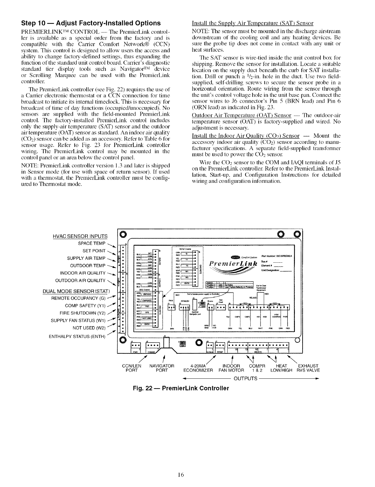
The PremierLink controller (see Fig. 22) requires the use of
a Canier electronic thermostat or a CCN connection for time
bl_)adcast to initiate its interred timeclock. This is necessm-y for
bl_)adcast of time of day functions (occupied/unoccupied). No
sensoLs me supplied with the field-mounted PmmierLink
control The factory-installed PremierLink control includes
only the supply-air temperature (SAT) sensor and the outdoor
air temperature (OAT) sensor as stan&trd+ An indoor air quality
(CO2) sensor can be added as an accessory. Refer to Table 6 for
sensor usage. Refer to Fig. 23 for PmmierLink controller
wiring+ The PremierLink control may be mounted in the
control panel or an mea below the control panel.
NOTE: PmmierLink controller version 1.3 and later is shipped
in Sensor mode (for use with space of mtum sensor). If used
with a thermostat, the PremierLink controller must be config-
ured to Thermostat mode.
Install the Supply Air Temperature (SAT) Sensor
NOTE: The sensor must be mounted in the discharge tfirstmam
downstream of the cooling coil and any heating devices. Be
sure the probe tip does not come in contact with any unit or
heat surfaces.
The SAT sensor is wire-tied inside the unit control box for
shipping. Remove the sensor for installation. Locate a suitable
location on the supply duct beneath the curb for SAT installa-
tion. Drill or punch a I/2-in. hole in the duct. Use two field-
supplied, self-drilling screws to secure the sensor probe in a
horizontal orientation. Route wiring from the sensor through
the unit's control voltage hole in the unit base pan. Connect the
sensor wires to J6 connector's Pin 5 (BRN lead) and Pin 6
(ORN lead) as indicated in Fig. 23.
Outdoor Air Temperature (OAT) Sensor -- The outdoor-air
temperature sensor ((-)AT) is factory-supplied and wired. No
adjustment is necessary.
Install the Indoor Air Quality (CO22 Sensor -- Mount the
accessory indoor air quality (COs) sensor according to manu-
facturer specifications. A sepm'ate field-supplied transformer
must be used to power the CO2 sensol:
Wire the CO2 sensor to the COM and IAQI termimds of J5
on the PremierLink controller Refer to the PremierLink Instal-
lation, Start-up, and Configuration Instructions for detailed
wiring and configuration information.
HVAC SENSOR INPUTS
SPACETEMP
SET POINT
SUPPLY AIR TEMP
OUTDOOR TEMP
INDOOR AIR QUALITY
OUTDOOR AIR QUALITY
DUAL MODE SENSOR (STAT)
COMP SAFETY (Y1)
FIRE SHUTDOWN (Y2)
SUPPLY FAN STATUS(W1)
NOT USED (W2)
ENTHALPY STATUS(ENTH) /
O O O
I ....... I
R_ I Pm_NlI,+bm: ItIC_P¢_
i _ +++_I_+i PremzerL_nk _,,=+,,+
im_" _l q ----"
%%:_II ,w+_ =, _7 u==+,+....
I J
] ¢m_ i +s_ + i r4 i
III = I_ ] +IIO_IEN[III 1 1111
.....m<2+++__ ./ ,] _++_m
- +
mm_
"++-++l.Iio +Iqq'l'l+'l'I
m_ .........
omm_
..................... .+J
/ t / f "4 "-4 "-.,
CCN/LEN NAVIGATOR 4+20MA INDOOR COMPR HEAT EXHAUST
PORT PORT ECONOMIZER PANMOTOR 1 &2 LOW/HIGH RVS VALVE
OUTPUTS
Fig. 22 -- PremierLink Controller
16
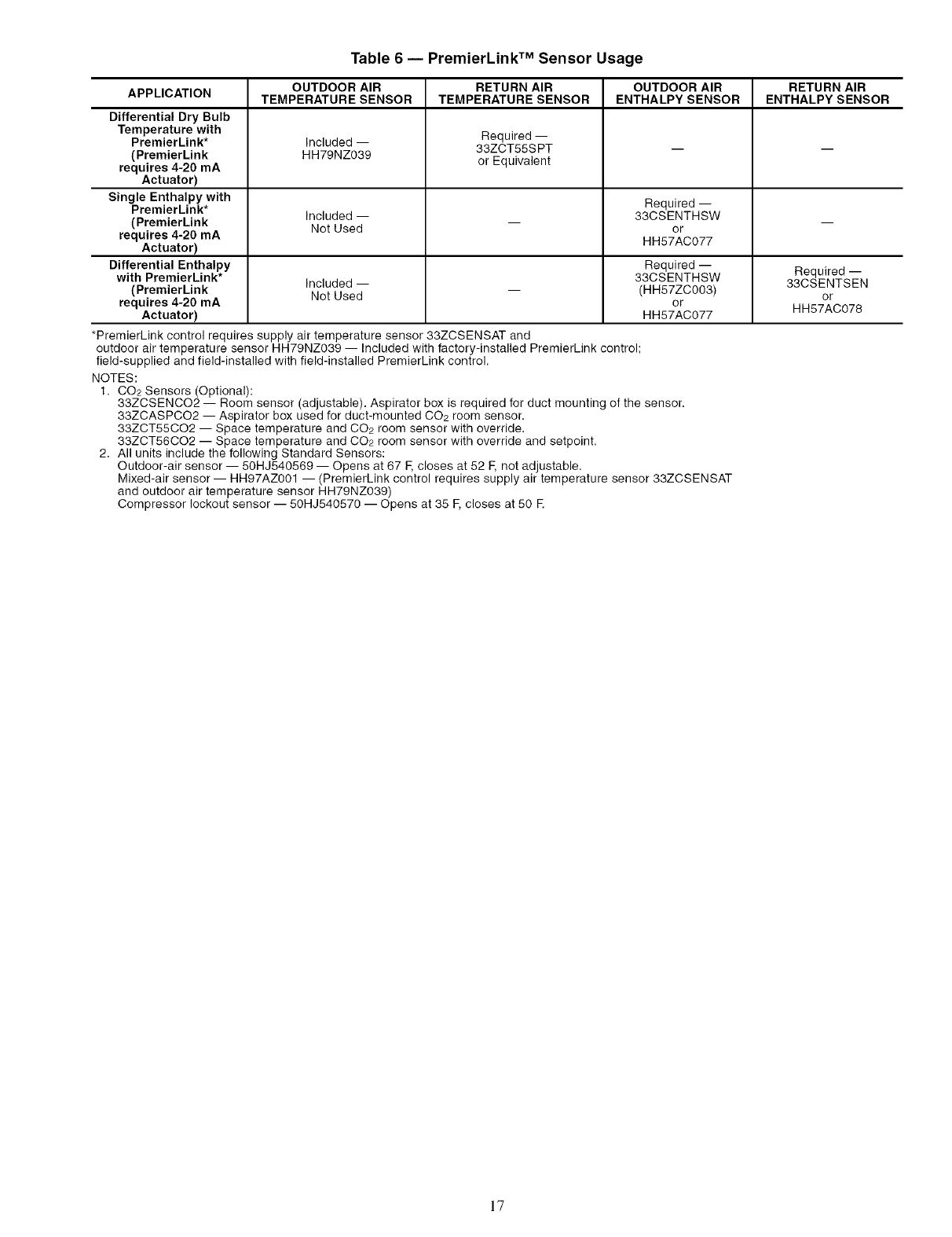
Table 6 -- PremierLink TM Sensor Usage
APPLICATION OUTDOOR AIR RETURN AIR OUTDOOR AIR RETURN AIR
TEMPERATURE SENSOR TEMPERATURE SENSOR ENTHALPY SENSOR ENTHALPY SENSOR
Differential Dry Bulb
Temperature with Required --
PremierLink* Included -- 33ZCT55S PT -- --
(PremierLink HH79NZ039
requires 4-20 mA or Equivalent
Actuator)
Single Enthalpy with Required --
PremierLink* Included -- 33CSENTHSW
(PremierLink Not Used -- or --
requires 4-20 mA HH57AC077
Actuator)
Differential Enthalpy Required -- Required-
with PremierLink* Included -- 33CSENTHSW 33CSENTSEN
(PremierLink Not Used -- (HH57ZC003) or
requires 4-20 mA or HH57AC078
Actuator) HH57AC077
*PremierLink control requires supply air temperature sensor 33ZCSENSAT and
outdoor air temperature sensor HH79NZ039 -- Included with factory-installed PremierLink control;
field-supplied and field-installed with field-installed PremierLink control.
NOTES:
1. CO2 Sensors (Optional):
33ZCSENCO2 -- Room sensor (adjustable). Aspirator box is required for duct mounting of the sensor.
33ZCASPCO2 -- Aspirator box used for duct-mounted CO2 room sensor.
33ZCT55CO2 -- Space temperature and CO2 room sensor with override.
33ZCT56CO2 -- Space temperature and CO2 room sensor with override and setpoint.
2. All units include the following Standard Sensors:
Outdoor-air sensor -- 50HJ540569 -- Opens at 67 F,closes at 52 F, not adjustable.
Mixed-air sensor -- HH97AZ001 -- (PremierLink control requires supply air temperature sensor 33ZCSENSAT
and outdoor air temperature sensor HH79NZ039)
Compressor lockout sensor -- 50HJ540570 -- Opens at 35 F, closes at 50 E
]7
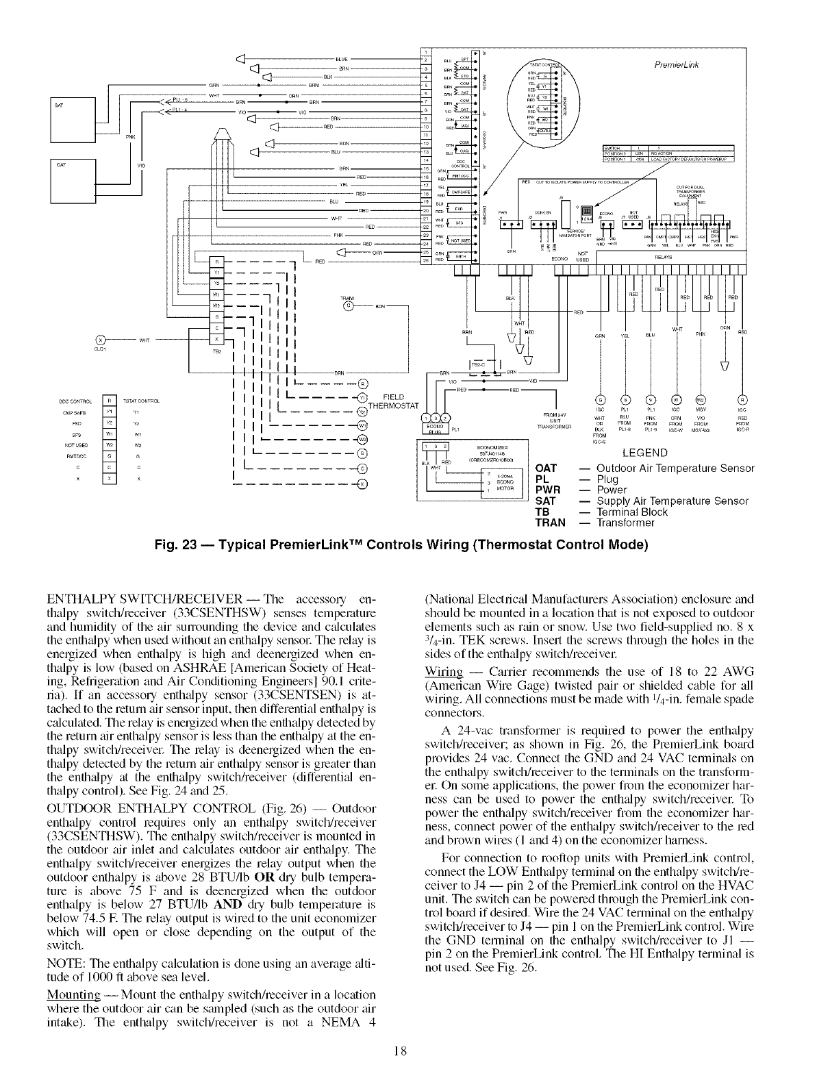
DDCCONTnOL
CMPSAFE
FSD
SFS
NOTUSEn
nMTOCC
C
X
TSTATCONTnOL
Y1
Y2
Wl
W2
G
C
X
®
_TH EFIMELDTAT
®
®
(D
©
Q
_c G
LEGEND
OAT -- Outdoor Air TemperatureSensor
PL -- Plug
PWR -- Power
SAT -- Supply Air TemperatureSensor
TB -- Terminal Block
TRAN -- Transformer
ECONOMIZE_
BOTJ401148
(CnECOMZn010B00)
Fig. 23 -- Typical PremierLink TM Controls Wiring (Thermostat Control Mode)
ENTHALPY SWITCH/RECEIVER -- The accessoly en-
thalpy switch/receiver (33CSENTHSW) senses temperature
and humidity of the air sulTounding the device and c_dculates
the enthalpy when used without an enthalpy sensoc The relay is
energized when enthalpy is high and deenergized when en-
thalpy is low (based on ASHRAE [American Society of Heat-
ing, Refrigeration and Air Conditioning Engineers] 90.1 crite-
ria). [f an accessol yenthalpy sensor (33CSENTSEN) is at-
tached to the return air sensor input, then differential enthalpy is
c_dculated. The relay is energized when the enlhalpy detected by
the return air enthalpy sensor is less than the enth_dpy at the en-
thalpy switch/receivec The relay is deenergized when the en-
thalpy detected by the return air enth_dpy sensor is gleater than
the enlh_dpy at the enthalpy switch/receiver (differential en-
thalpy control). See Fig. 24 and 25.
OUTDOOR ENTHALPY CONTROL (Fig. 26) -- Outdoor
enthalpy control lequires only an enth_dpy switch/receiver
(33CSENTHSW). The enthalpy switch/receiver is mounted in
the outdoor air inlet and calculates outdoor air enthalpy. The
enthalpy switch/receiver enelgizes the relay output when the
outdoor enthalpy is above 28 BTU/Ib OR dry bulb tempera-
ture is above 75 F and is deenergized when the outdoor
enthalpy is below 27 BTU/Ib AND diy bulb temperature is
below 74.5 E The relay output is wired to the unit economizer
which will open or close depending on the output of the
switch.
NOTE: The enlhalpy calculation is done using an average _dti-
tude of 1000 ft above sea level.
Mounting -- Mount lhe enthalpy switch/receiver in a location
where the outdoor air can be smnpled (such as the outdoor air
intake). The enthalpy switch/receiver is not a NEMA 4
(National Electrical Manufacturers Association) enclosure and
should be mounted in a location that is not exposed to outdoor
elements such as rain or snow. Use two field-supplied no. 8 x
3/4-in. TEK sclews. Insert the screws through the holes in the
sides of the enthalpy switch/receivec
Wiring -- Carrier recommends the use of 18 to 22 AWG
(American Wire Gage) twisted pair or shielded cable for all
wiring. All connections must be made with l/4-in, female spade
connectors.
A 24-vac transformer is required to power the enthalpy
switch/receiver; as shown in Fig. 26, lhe PlemierLink botud
provides 24 vac. Connect the GND and 24 VAC terminals on
the enlhalpy switchheceiver to lhe terminals on lhe tmnsform-
ec On some applications, the power from the economizer har-
ness can be used to power the enth'.Apy switch/receivec To
power the enthalpy switch/receiver from the economizer har-
ness, connect power of the enthalpy switchheceiver to the led
and brown wires (1 and 4) on the economizer harness.
For connection to rooftop units with PremierLink control,
connect the LOW Enthalpy termimfl on lhe enthalpy switch/re-
ceiver to J4 -- pin 2 of the PlemierLink control on the HVAC
unit. The switch can be powered through the PremierLink con-
trol board if desired. Wire the 24 VAC terminal on lhe enthalpy
switchheceiver to J4 -- pin 1 on the PremierLink control. Wire
the GND termin:d on the enthalpy switch/receiver to Jl --
pin 2 on the PremierLink control The HI Enthalpy terminal is
not used. See Fig. 26.
18
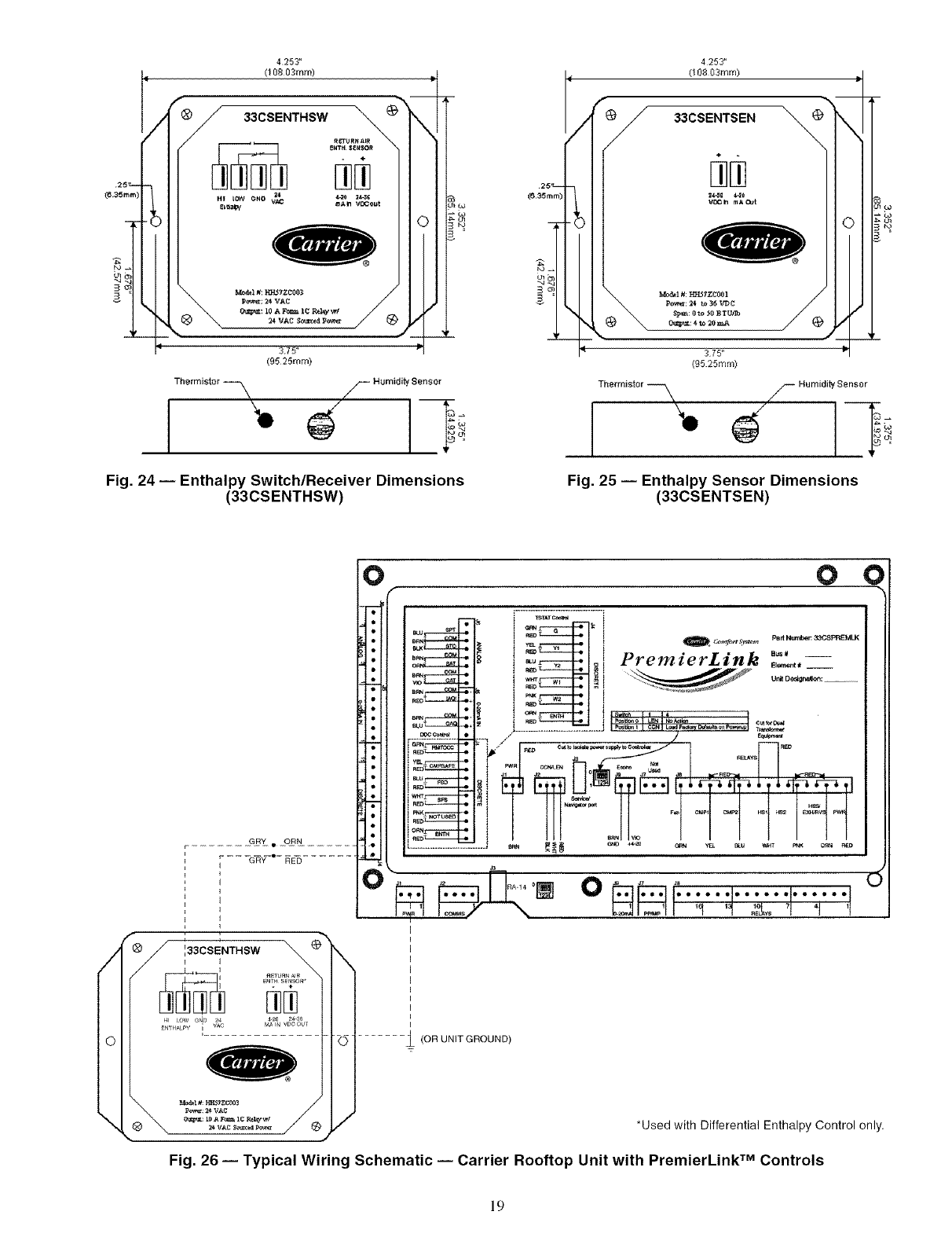
@
Thermistor FHumidity Sensor Thermistor
1.
S Humidity Sensor
Fig. 24 -- Enthalpy Switch/Receiver Dimensions
(33CSENTHSW) Fig. 25 -- Enthalpy Sensor Dimensions
(33CSENTSEN)
/
\
...... .gB_....9.ON... ......
- - - -G_Y--'- _E_ .......
0 0 ¢
I
I
I
I
I
I
I
I
I
I
__ (OR UNIT GROUND)
T_T_T_ I
_U SPT _O_ {
IPart Nurn_m 33CSPREMLK
I_K _r_ 1 _ c_ei maP_ _i _2 _v pw
*Used with Differential Enthalpy Control only.
Fig. 26 -- Typical Wiring Schematic -- Carrier Rooftop Unit with PremierLink TM Controls
19
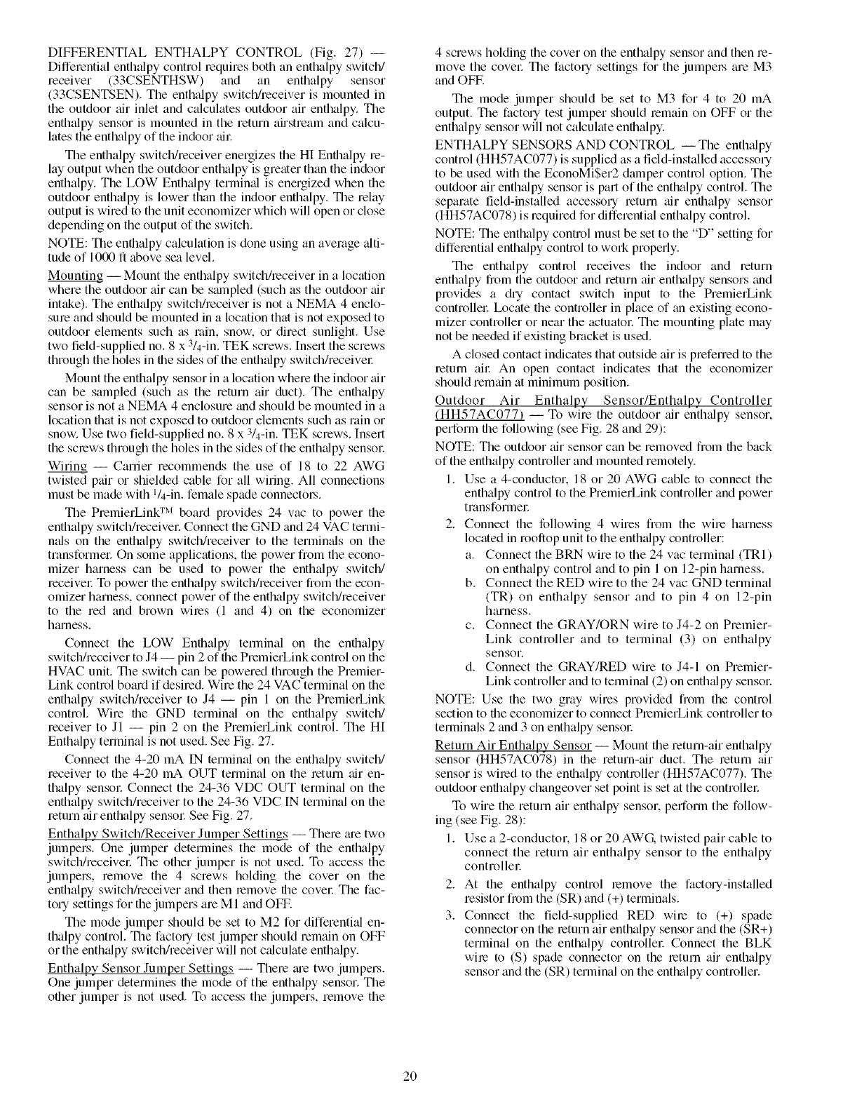
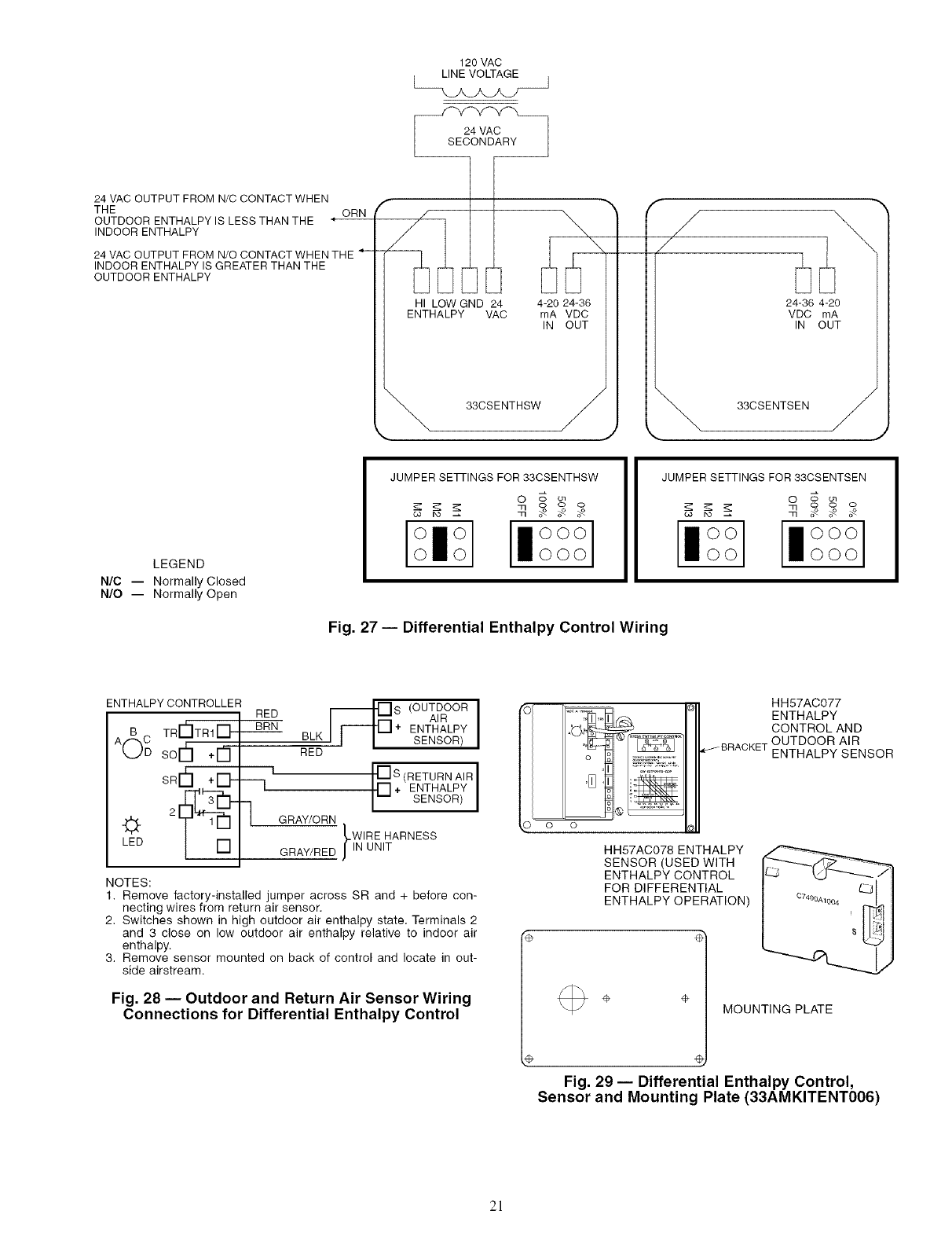
DIFFERENTIAL ENTHALPY CONTROL (Fig. 27) --
Differential enthalpy control requires both an enthalpy switch/
receiver (33CSENTHSW) and an enthalpy sensor
(33CSENTSEN). The enthalpy switch/receiver is mounted in
the outdoor air inlet and calculates outdoor air enthalpy. The
enthalpy sensor is mounted in the return airstream and calcu-
lates the enthalpy of the indoor ail:
The enthalpy switch/receiver energizes the HI Enthalpy re-
lay output when the outdoor enthalpy is greater than the indoor
enthalpy. The LOW Enthalpy terminal is energized when the
outdoor enthalpy is lower than the indoor enthalpy. The relay
output is wired to the unit economizer which will open or close
depending on the output of the switch.
NOTE: The enthalpy calculation is done using an average alti-
tude of 1000 ft above sea level.
Mounting -- Mount the enthalpy switch/receiver in a location
where the outdoor air can be smnpled (such as the outdoor air
intake). The enthalpy switch/receiver is not a NEMA 4 enclo-
sure and should be mounted in a location that is not exposed to
outdoor elements such as rain, snow, or direct sunlight. Use
two field-supplied no. 8 x 3/4-in. TEK screws. Insert the screws
through the holes in file sides of the enthtflpy switch/receivel:
Mount the enthalpy sensor in a location where the indoor air
can be sampled (such as the return air duct). The enflialpy
sensor is not a NEMA 4 enclosure trod should be mounted in a
location flint is not exposed to outdoor elements such as rain or
snow. Use two field-supplied no. 8 x 3/4-in. TEK screws. Insert
the screws through the holes in the sides of the enthalpy sensol:
Wiring -- Carrier recommends the use of 18 to 22 AWG
twisted pair or shielded cable for all wiring. All connections
must be made with l/4-in, female spade connectol.s.
The PremierLink TM board provides 24 vac to power the
enthalpy switch/receivel: Connect the GND and 24 VAC termi-
nals on the enthalpy switch/receiver to the termimfls on the
transformer On some applications, the power from the econo-
mizer harness can be used to power the enthalpy switch/
receivel: To power the enthalpy switch/receiver from the econ-
omizer harness, connect power of the enthalpy switch/receiver
to the red and brown wires (1 and 4) on the economizer
hmness.
Connect the LOW Enthalpy terminal on the enthalpy
switch/receiver to J4 -- pin 2 of the PremierLink control on the
HVAC unit. The switch can be powered through the Premier-
Link control bo_ud if desired. Wire the 24 VAC terminal on the
enthalpy switch/receiver to J4 -- pin 1 on the PremierLink
control. Wire file GND terminal on the enthalpy switch/
receiver to Jl -- pin 2 on the PremierLink control. The HI
Enthalpy terminal is not used. See Fig. 27.
Connect the 4-20 mA IN terminal on the enthalpy switch/
receiver to the 4-20 mA OUT terminal on the return air en-
thalpy sensol: Connect the 24-36 VDC OUT terminal on the
enthalpy switch/receiver to the 24-36 VDC IN terminal on the
return air enthalpy sensor See Fig. 27.
Enthalpy Switch/Receiver Jumper Settings -- There me two
jumpers. One jumper determines the mode of the enthalpy
switch/receivel: The other jumper is not used. To access the
jumpers, remove the 4 screws holding the cover on the
enthalpy switch/receiver and then lemove the covel: The fac-
tory settings for the jumpers are M 1 and OFF.
The mode jumper should be set to M2 for differentkfl en-
thalpy control. The factory test jumper should remain on OFF
or the enthtflpy switch/receiver will not calculate enthalpy.
Enthalpy Sensor Jumper Settings -- There me two jumpers.
One jumper determines the mode of the enthalpy sensor. The
other jumper is not used. To access the jumpers, remove the
4 screws holding the cover on the enthalpy sensor and then m-
move the covet The factory settings for the jumpel,s am M3
and OFF.
The mode jumper should be set to M3 for 4 to 20 mA
output. The factory test jumper should remain on OFF or the
enthalpy sensor will not calculate enflialpy.
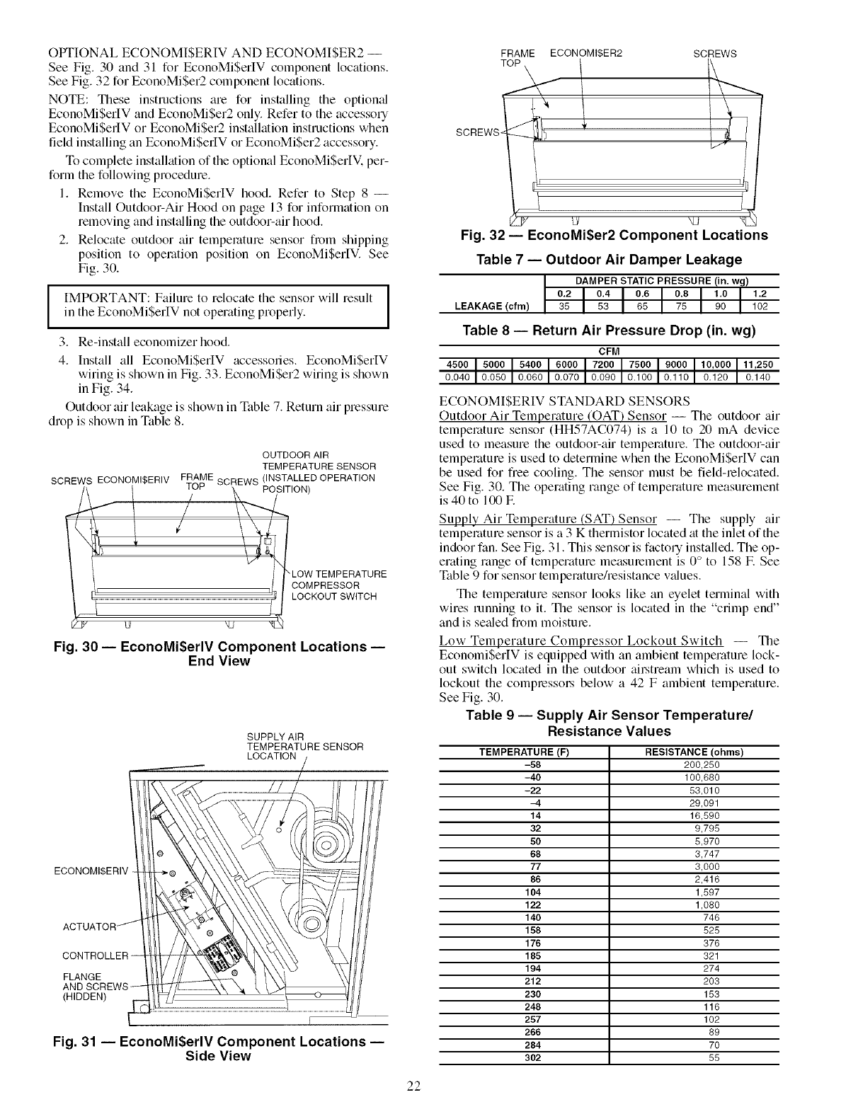
ENTHALPY SENSORS AND CONTROL -- The enthalpy
control (HH57AC077) is supplied as a field-installed accessory
to be used with the EconoMi$er2 damper control option. The
outdoor air enth_dpy sensor is part of the enthalpy control. The
separate field-installed accessory return air enflialpy sensor
(HH57AC078) is required for differential enthalpy control.
NOTE: The enthalpy control must be set to the "D" setting for
differential enthalpy control to work properly.
The enthalpy control receives the indoor and return
enthalpy from the outdoor and return air enthalpy sensors and
provides a dry contact switch input to the PremierLink
controllel: Ix)cate the controller in place of gin existing econo-
mizer controller or near the actuatol: The mounting plate may
not be needed if existing bracket is used.
A closed contact indicates that outside air is preferred to the
mtum ail: An open contact indicates that the economizer
should remain tit minimum position.
Outdoor Air Enthalpy Sensor/Enthalpy Controller
(HH57AC077) -- To wire the outdoor air enthtflpy sensor,
perform file following (see Fig. 28 and 29):
NOTE: The outdoor air sensor can be removed from file back
of the enthalpy controller and mounted remotely.
1. Use a 4-conductor, 18 or 20 AWG cable to connect the
enthalpy control to the PremierLink controller and power
transformeg
2. Connect the following 4 wires from the wire harness
located in rooftop unit to the enthtdpy controller:
a. Connect the BRN wire to the 24 vac terminal (TRI)
on enthalpy control and to pin 1 on 12-pin harness.
b. Connect the RED wire to the 24 vac GND terminal
(TR) on enthalpy sensor and to pin 4 on 12-pin
harness.
c. Connect the GRAY/ORN wire to J4-2 on Premier-
Link controller and to terminal (3) on enthalpy
sensoE
d. Connect the GRAY/RED wire to J4-1 on Premier-
Link controller and to terminal (2) on enthtdpy sensol:
NOTE: Use the two gray wires provided from the control
section to the economizer to connect PmmierLink controller to
terminals 2 and 3 on enthalpy sensol:
Return Air Enthalpy Sensor -- Mount the return-air enthalpy
sensor (HH57AC078) in file return-air duct. The return air
sensor is wired to the enflialpy controller (HH57AC077). The
outdoor enthalpy changeover set point is set at the controllel:
To wire the return air enthalpy sensor, perform the follow-
ing (see Fig. 28):
1. Use a 2-conductor, 18 or 20 AWG, twisted pair cable to
connect the return air enthalpy sensor to the enthalpy
controllel:
2. At the enthalpy control remove the factory-installed
resistor fi_m the (SR) and (+) terminals.
3. Connect the field-supplied RED wire to (+) spade
connector on the return air enthalpy sensor and the (SR+)
terminal on the enthalpy controllel: Connect the BLK
wire to (S) spade connector on the mtum air enthalpy
sensor and the (SR) terminal on the enthalpy controller.
2O
120 VAC
LINE VOLTAGE
k._,.J_Aj--
24 VAC OUTPUT FROM N/C CONTACT WHEN
THE ORN
OUTDOOR ENTHALPY IS LESS THAN THE "
INDOOR ENTHALPY
24 VAC OUTPUT FROM N/O CONTACT WHEN THE
INDOOR ENTHALPY IS GREATER THAN THE
OUTDOOR ENTHALPY
HI LOW GND 24 4-20 24-36
ENTHALPY VAC rnA VDC
IN OUT
"_, 33CSENTHSW /
J
/F
24-36 4-20
VDC rnA
IN OUT
_, 33CSENTSEN /
LEGEND
N/C -- Normally Closed
N/O -- Normally Open
JUMPER SE_INGS FOR 33CSENTHSW
[ °1[a°°°l
O010 OOO
Fig. 27 -- Differential Enthalpy Control Wiring
JUMPER SETTINGS FOR 33CSENTSEN
O _ ol
[ioOOI [ioOoOoO1
ENTHALPYCONTROLLER
RED _S (OUTDOORAIR I
TRI-_ITR1i'-LI,_IL_I BRN + ENTHALPY
BLK SENSOR)
A(_Csorh+E3--
SR¢-I+[]-
LED
--1
RED
I [] S (RETURN AIR I
[] + ENTHALPY
SENSOR
GRAY/ORN
LWIRE HARNESS
GRAY/RED JlN UNIT
NOTES:
1. Remove factory-installed jumper across SR and + before con-
necting wires from return air sensor.
2, Switches shown in high outdoor air enthalpy state. Terminals 2
and 3 close on low outdoor air enthalpy relative to indoor air
enthalpy.
3. Remove sensor mounted on back of control and locate in out-
side airstream.
Fig. 28 -- Outdoor and Return Air Sensor Wiring
Connections for Differential Enthalpy Control
HH57AC077
ENTHALPY
CONTROLAND
OUTDOOR AIR
ENTHALPY SENSOR
HH57AC078 ENTHALPY
SENSOR (USED WITH
ENTHALPY CONTROL
FOR DIFFERENTIAL
ENTHALPY OPERATION)
÷MOUNTING PLATE
4!
Fig. 29- Differential Enthalpy Control,
Sensor and Mounting Plate (33AMKITENT006)
21
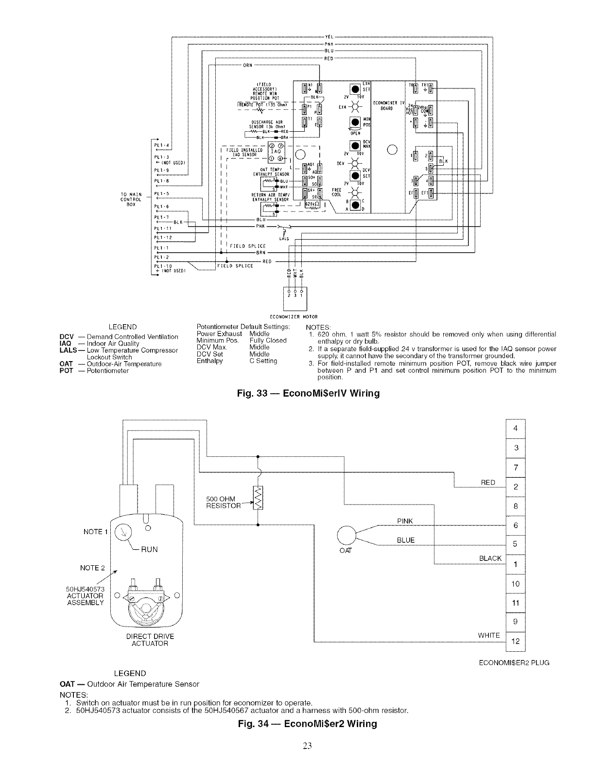
OPTIONAL ECONOMISERIV AND ECONOMISER2 --
See Fig. 30 and 31 for EconoMiSerIV component locations.
See Fig. 32 for EconoMi$er2 component locations.
NOTE: These instructions are for installing the optiomd
EconoMiSerIV and EconoMiSer2 only. Refer to the accessory
EconoMiSerIV or EconoMiSer2 installation instructions when
field installing an EconoMi$erIV or EconoMiSer2 accessory.
To complete installation of the optional EconoMiSerIV. per-
form the following procedure.
1. Remove the EconoMiSerlV hood. Refer to Step 8 --
Install Outdoor-Air Hood on page 13 for information on
removing and inst_flling the outdoor-air hood.
2. Relocate outdoor air temperature sensor from shipping
position to operation position on EconoMiSerIV. See
Fig. 30.
I
IMPORTANT: Failure to relocate the sensor will result I
in the EconoMiSerIV not operating properly. I
3. Re-install economizer hood.
4. Install all EconoMiSerIV accessories. EconoMiSerIV
wiring is shown in Fig. 33. EconoMiSer2 wiring is shown
in Fig. 34.
Outdoor air leakage is shown in Table 7. Return air pressure
drop is shown in Table 8.
OUTDOOR AIR
TEMPERATURE SENSOR
SCREWS ECONOMI$ERIV FRAME SCREWS (INSTALLED OPERATION
/\ / \ POSiT,ON)
,/
LOW TEMPERATURE
COMPRESSOR
LOCKOUT SWITCH
Fig. 30- EconoMi$erlV Component Locations --
End View
SUPPLY AIR
TEMPERATURE SENSOR
LOCATION
ECONOMI$ERIV
FLANGE
(HIDDEN)
Fig. 31 -- EconoMiSerlV Component Locations --
Side View
FRAME ECONOMI$ER2 SCREWS
TOP
SCREWS
Fig. 32 -- EconoMi$er2 Component Locations
Table 7 -- Outdoor Air Damper Leakage
DAMPER STATIC PRESSURE (in. wg)
0.2 0.4 0.6 0.8 1.0 1.2
LEAKAGE (cfm) 35 53 65 75 90 102
Table 8 -- Return Air Pressure Drop (in. wg)
CFM
4500 5000 5400 6000 7200 7500 9000 10,000 11,250
0,040 0.050 0,060 0,070 0,090 0.100 0,110 0,120 0,140
ECONOMI$ERIV STANDARD SENSORS
Outdoor Air Temperature (OAT) Sensor -- The outdoor air
temperature sensor (HH57AC074) is a 10 to 20 mA device
used to measure the outdoor-air temperature. The outdoor-air
temperature is used to determine when the EconoMiSerIV can
be used for free cooling. The sensor must be field-lelocated.
See Fig. 30. The operating range of temperature measurement
is 40 to 100E
Supply Air Temperature (SAT) Sensor -- The supply air
temperature sensor is a 3 K thermistor located at the inlet of the
indoor fan. See Fig. 31. This sensor is factory installed. The op-
erating range of temperature measmement is 0° to 158 IF.See
Table 9 for sensor temperature/resistance v_dues.
The temperature sensor looks like an eyelet terminal with
wires running to it. The sensor is located in the "crimp end"
and is settled from moisture.
Low Temperature Compressor Lockout Switch -- The
EconomiSerIV is equipped with an ambient temperature lock-
out switch located in the outdoor alLstream which is used to
lockout the compressoLs below a 42 F ambient temperature.
See Fig. 30.
Table 9 -- Supply Air Sensor Temperature/
Resistance Values
TEMPERATURE (F) RESISTANCE (ohms)
-58 200,250
-40 100,680
-22 53,010
-4 29,091
14 16,590
32 9,795
50 5,970
68 3,747
77 3,000
86 2,416
104 1,597
122 1,080
140 746
158 525
176 376
185 321
194 274
212 203
230 153
246 116
257 102
266 89
284 70
302 55
22
TO MAIN
CONTROL
BOX
P_
PLI*R
(NOT USED)
P(LI_8
Pckt - 5
PLI "9
PL1 =I
(
PR1 =R
PLI _ID
(ROT USED)
LEGEND
DCV -- Demand Controlled Ventilation
IAQ -- Indoor Air Quality
LALS-- Low Temperature Compressor
Lockout Switch
OAT -- Outdoor-Air Temperature
POT -- Potentiometer
YEL
PNK
-BLU
RED
--ORN {FIELD _NI _ _ EXHsEI
ACCESSORY) 4, ,__,
REI4OTEWIN
POSITION ROT BLK _V ]OV
SENSOR (3k Ohm) PO_
B_.X--I-RE D -
,AOSE._OL_k_ LP I _ ,0v
L_ ) AO RCV
OAT TEWP/ L- _4,.n_ _DCV
E_INALPY_LH__S+OSE_SOR _ _ 2V_ovSET
I I DLU
I I P"--_
) FIELD SPLICE LALS
L(DRN
FIE'LLD SPLICE RED )
EDONOMI ZER NOTOR
Potentiometer Default Settings: NOTES:
Power Exhaust Middle
Minimum Pos. Fully Closed
DCV Max. Middle
DCV Set Middle
Enthalpy C Setting
ECONOMISER Ii
BOARD
0,[
,[
1, 620 ohm, 1 watt 5% resistor should be removed only when using differential
enthalpy or dry bulb,
2, If a separate field-supplied 24 v transformer is used for the IAQ sensor power
supply, it cannot have the secondary of the transformer grounded.
3, For field-installed remote minimum position POT, remove black wire jumper
between P and P1 and set control minimum position POT to the minimum
position,
Fig. 33 -- EconoMi$erlV Wiring
NOTE 1
NOTE2
/
50HJ540573
ACTUATOR
ASSEMBLY
RUN
DIRECT DRIVE
ACTUATOR
500 OHM
RESISTO R---"L_
OAT
PINK
BLUE
RED
BLACK
WHITE
4
3
7
2
8
6
5
1
10
11
9
12
ECONOMI$ER2 PLUG
LEGEND
OAT -- Outdoor Air Temperature Sensor
NOTES:
1. Switch on actuator must be in run position for economizer to operate.
2. 50HJ540573 actuator consists of the 50HJ540567 actuator and a harness with 500-ohm resistor.
Fig. 34 -- EconoMi$er2 Wiring
23
ECONOMISERIV CONTROL MODES
IMPORTANT: The optional EconoMiSer2 does not
include a controllel: The EconoMiSer2 is operated by a 4 to
20 mA signal from an existing field-supplied controller
(such as PremierLink TM control). See Fig. 34 for wiring
information.
Determine the EconoMiSerIV control mode before set up of
the control. Some modes of operation may lequile diffelent sen-
sors. Refer to Table 10. The EconoMiSerlV is supplied from the
factory with a supply air temperature sensor, a low temperature
compressor lockout switch, and an outdoor air temperature
sensol: This _fllows for operation of the EconoMiSerlV with
outdoor air &y bulb changeover control. Additional accesso-
ries can be added to allow for different types of changeover
control and operation of the EconoMiSerlV and unit.
Table 10 -- EconoMi$erlV Sensor Usage
APPLICATION
Outdoor Air
Dry Bulb
Differential
Dry Bulb
Single Enthalpy
Differential
Enthalpy
002 for DCV
Control using a
Wall-Mounted
CO2 Sensor
CO2 for DCV
Control using a
Duct-Mounted
CO2 Sensor
ECONOMI$ER IV WITH OUTDOOR AIR
DRY BULB SENSOR
Accessories Required
None. The outdoor air dry bulb sensor
is factory installed.
CRTEMPSN002A00*
HH57AC078
HH57AC078
and
CRENTDIF004A00*
33ZCSENCO2
33ZCSENCO2t
and CRCBDIOX005A00tt
33ZCASPCO2**
*CRENTDIF004A00 and CRTEMPSN002A00 accessories are used on
many different base units. As such, these kits may contain parts that
will not be needed for installation.
1-33ZCSENCO2 is an accessory CO2 sensor.
**33ZCASPCO2 is an accessory aspirator box required for duct-
mounted applications.
1-]-CRCBDiOX005A00 is an accessory that contains both 33ZCSENCO2
and 33ZCASPCO2 accessories.
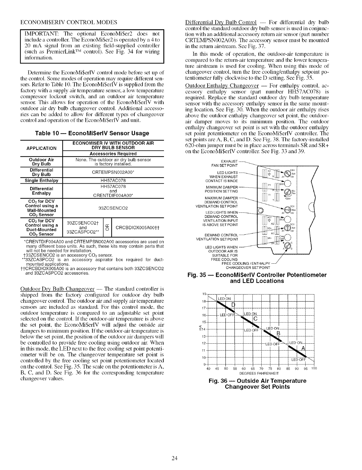
Outdoor Dry Bulb Changeover -- The standard controller is
shipped from the factory configured for outdoor dry bulb
changeover control. The outdoor air and supply air temperature
sensol_ are included as stan&trd. For this control mode, the
outdoor temperature is compmed to an adjustable set point
selected on the control. If the outdoor-air temperature is above
the set point, the EconoMiSerIV will adjust the outside air
dampers to minimum position. If the outdoor-air temperature is
below the set point, the position of the outdoor air dampers will
be controlled to provide free cooling using outdoor air. When
in this mode, the LED next to the free cooling set point potenti-
ometer will be on. The changeover temperature set point is
controlled by the free cooling set point potentiometer located
on the control. See Fig. 35. The sc_de on the potentiometer is A,
B, C, and D. See Fig. 36 for the conesponding temperature
changeover v_dues.
Differential DLy Bulb Control -- For differential dry bulb
control the standard outdoor dry bulb sensor is used in conjunc-
tion with an additional accessory return air sensor (part number
CRTEMPSN002A00). The accessory sensor must be mounted
in the return airstream. See Fig. 37.
In this mode of operation, the outdoor-tfir temperature is
compared to the return-air temperature and the lower tempera-
ture airstream is used for cooling. When using this mode of
changeover control, turn the free cooling/enthalpy setpoint po-
tentiometer fully clockwise to the D setting. See Fig. 35.
Outdoor Enthalpy Changeover -- For enthalpy control, ac-
cessory enthalpy sensor (p_ut number HH57AC078) is
required. Replace the standard outdoor dry bulb temperature
sensor with the accessory enthalpy sensor in the same mount-
ing location. See Fig. 30. When the outdoor air enthalpy rises
above the outdoor enthalpy changeover set point, the outdoor-
air damper moves to its minimum position. The outdoor
enthalpy changeover set point is set with the outdoor enth_dpy
set point potentiometer on the EconoMiSerIV controllel: The
set points are A, B, C, and D. See Fig. 38. The factory-installed
620-ohln jumper must be in place across terminals SR and SR+
on the EconoMiSerIV controllel: See Fig. 33 and 39.
FAN SET POINT
WHEN EXHAUST
CONTACT tS MADE
MINIMUM
POSITION SETTING
MAXIMUM
DEMAND CONTROL
VENTILATION SET POINT
LED LIGHTS
DEMAND CONTROL
VENTILATION INPUT
IS ABOVE SET POINT
VENTILATION SET POINT
LED LIGHTS WHEN
OUTDOOR AiR iS
SUITABLE FOR
FREE COOLING
FREE COOLING/ENTHALPY
CHANGEOVER SET POINT
Fig. 35 -- EconoMi$erlV Controller Potentiometer
and LED Locations
18-!_
17-i
16_ -- - LED OFF LED ON
<15" I
E14- ! LED OFF -
13"
12-
4O 45 50 55 60
[ L
LED O;
_'-_L_ LED ON- --
65 70 75 80 85 90 95 100
DEGREES FAHRENHEIT
Fig. 36 -- Outside Air Temperature
Changeover Set Points
24
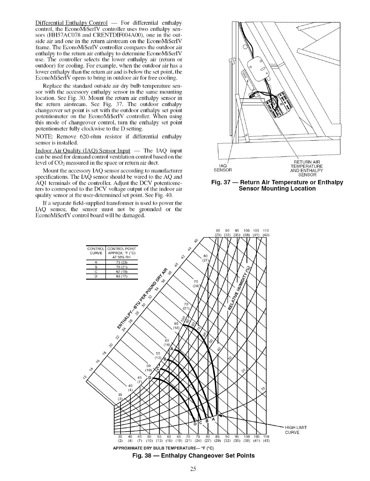
Differential Enthalpy Control -- For differential enthalpy
control, the EconoMiSerIV controller uses two enthalpy sen-
sors (HH57AC078 and CRENTDIF004A00), one in the out-
side air and one in the return airstream on the EconoMiSer[V
frame. Tile EconoMiSerIV controller compares the outdoor air
enthalpy to file return air enthalpy to determine EconoMiSer[V
use. Tile controller selects the lower enthalpy air (return or
outdoor) for cooling. For example, when file outdoor air has a
lower enthalpy than the return air and is below the set point, the
EconoMiSerIV opens to bring in outdoor _firfor fiee cooling.
Replace the standard outside air dUbulb temperature sen-
sor with the accessory enthalpy sensor in the stone mounting
location. See Fig. 30. Mount the return air enth_dpy sensor in
the return airstremn. See Fig. 37. Tile outdoor enth_dpy
changeover set point is set with the outdoor enthalpy set point
potentiometer on the EconoMiSerIV controller. When using
this mode of changeover control, turn the enthalpy set point
potentiometer fully clockwise to the D setting.
NOTE: Remove 620-ohm resistor if differentkd enthalpy
sensor is installed,
Indoor Air Ouality (IAO) Sensor Input -- Tile IAQ input
can be used for demand control ventilation control based on the
level of CO2 measured in the space or return air duct.
Mount the accessory IAQ sensor according to manufacturer
specifications. The IAQ sensor should be wired to the AQ and
AQI terminals of the controllel: Adjust the DCV potentiome-
ters to conespond to the DCV voltage output of the indoor air
quality sensor at the use>determined set point. See Fig. 40.
If a separate field-supplied transformer is used to power the
IAQ sensol: the sensor must not be grounded or the
EconoMiSer[V control board will be &imaged.
RETURN AIR
IAQ TEMPERATURE
SENSOR AND ENTHALPY
SENSOR
Fig. 37 -- Return Air Temperature or Enthalpy
Sensor Mounting Location
CONTROL CONTROLPOINT
CURVE APPROXI°F (°C)
AT 50% RH
A 73(23)
B 70(21)
C 67119 )
D 63(17)
35 40
(2) (4)
85 90 95 100 105 110
(29) (32) (35) (38) (41) (43)
i
i
i
i
i
i
i
i
ii
i
i
i
i
i
i
i
_ HIGH LIMIT
i
\ CURVE
45 50 55 60 65 70 75 80 85 90 95 100 105 110
(7) (10) (13) (16) (18) (21) (24) (27) (29) (32) (35) (38) (41) (43)
APPROXIMATE DRY BULB TEMPERATURE-- °F (°C)
Fig. 38 -- Enthalpy Changeover Set Points
25
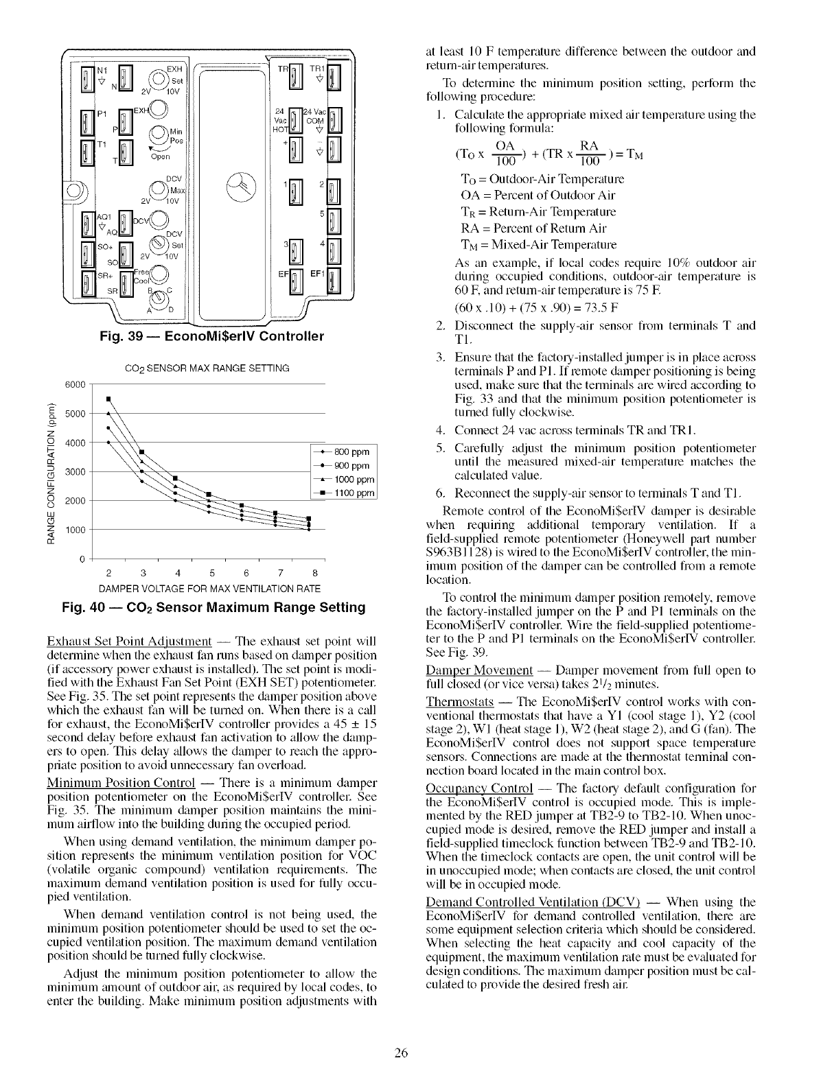
FFr_I EF1
T
....... @
2
5
....._ 4
Fig. 39- EconoMi$erlV Controller
6000
5000
z
Q 4000
3000
Z
2000
z 1000
<
CO 2 SENSOR MAX RANGE SETTING
+800 ppm
__ _ 9o0 ppm
1000 ppm
+1100 ppm
2345678
DAMPER VOLTAGE FOR MAX VENTILATION RATE
Fig. 40 -- 002 Sensor Maximum Range Setting
Exhaust Set Point Adjustment -- The exhaust set point will
determine when the exhaust fan runs based on dmnper position
(if accessol 7 power exhaust is installed). The set point is modi-
fied with the Exhaust Fan Set Point (EXH SET) potentiometel:
See Fig. 35. The set point replesents file &tmper position above
which the exhaust fan will be turned on. When there is a c_dl
for exhaust, the EconoMi$erlV controller provides a 45 _+15
second delay before exhaust fan activation to allow the damp-
ers to open. This delay _dlows the damper to reach the appro-
priate position to avoid unnecessary fan overload.
Minimum Position Control -- There is a minimum damper
position potentiometer on the EconoMi$erlV controllel: See
Fig. 35. The minimum &tmper position maintains the mini-
mum airflow into the building during the occupied period.
When using demand ventilation, the minimum dmnper po-
sition represents the minimum ventilation position for VOC
(volatile organic compound) ventilation requilements. The
maximum demand ventilation position is used for fully occu-
pied ventilation.
When demand ventilation control is not being used, the
minimum position potentiometer should be used to set the oc-
cupied ventilation position. The maximum demand ventilation
position should be turned fully clockwise.
Adjust the minimum position potentiometer to allow the
minimum mnount of outdoor air. as required by local codes, to
enter the building. Make minimum position adjustments with
at least 10 F temperature difference between the outdoor and
return-air temperatures.
To determine the minimum position setting, perform the
following procedure:
1. Calculate the appropriate mixed air temperature using the
following formula:
OA RA
(To x I---_T ) + (TR x _ ) = TM
To = Outdoor-Air Temperature
OA = Percent of Outdoor Air
TR = Return-Air Temperature
RA = Percent of Return Air
TM = Mixed-Air Temperature
As an example, if local codes require 10% outdoor air
during occupied conditions, outdoor-air temperature is
60 IF.and return-air temperature is 75 E
(60 x. 10) + (75 x .90) = 73.5 F
2. Disconnect the supply-air sensor from terminals T and
TI.
3. Ensure that the factory-installed jumper is in place across
terminals P and PI. If remote &tmper positioning is being
used, make sure that the termimds are wired according to
Fig. 33 and that the minimum position potentiometer is
turned fully clockwise.
4. Connect 24 vac across termimds TR and TRI.
5. Cmefully adjust the minimum position potentiometer
until the measured mixed-air temperature matches the
calculated v_due.
6. Reconnect the supply-air sensor to terminals T and TI.
Remote control of the EconoMi$erIV dmnper is desirable
when requiring additional temporm 7 ventilation. If a
field-supplied remote potentiometer (Honeywell part number
$963B1128) is wired to the EconoMiSerIV controller, the min-
imum position of the &tmper can be controlled from a remote
location.
To control the minimum dalnper position remotely, remove
the factory-installed jumper on the P and PI terminals on the
EconoMiSerIV controllel: Wire the field-supplied potentiome-
ter to the P and PI terminals on the EconoMiSerIV controllel:
See Fig. 39.
Damper Movement -- Damper movement from full open to
full closed (or vice versa) takes 21/2 minutes.
Thermostats -- The EconoMi$erIV control works with con-
ventional thermostats that have a YI (cool stage 1), Y2 (cool
stage 2), WI (heat stage 1), W2 (heat stage 2), and G (fan). The
EconoMi$erIV control does not support space temperature
sensors. Connections are made at the thermostat terminal con-
nection board located in the main control box.
Occupancy Control -- The factory default configuration for
the EconoMi$erIV control is occupied mode. This is imple-
mented by the RED jumper at TB2-9 to TB2-10. When unoc-
cupied mode is desired, remove the RED jumper and install a
field-supplied timeclock function between TB2-9 and TB2-10.
When the timeclock contacts are open, the unit control will be
in unoccupied mode; when contacts are closed, file unit control
will be in occupied mode.
Demand Controlled Ventilation (DCV) -- When using the
EconoMi$erIV for demand controlled ventilation, there are
some equipment selection criteria which should be considered.
When selecting the heat capacity and cool capacity of the
equipment, the maximum ventilation rote must be evaluated for
design conditions. The maximum damper position must be cal-
culated to provide the desired fresh all:
26
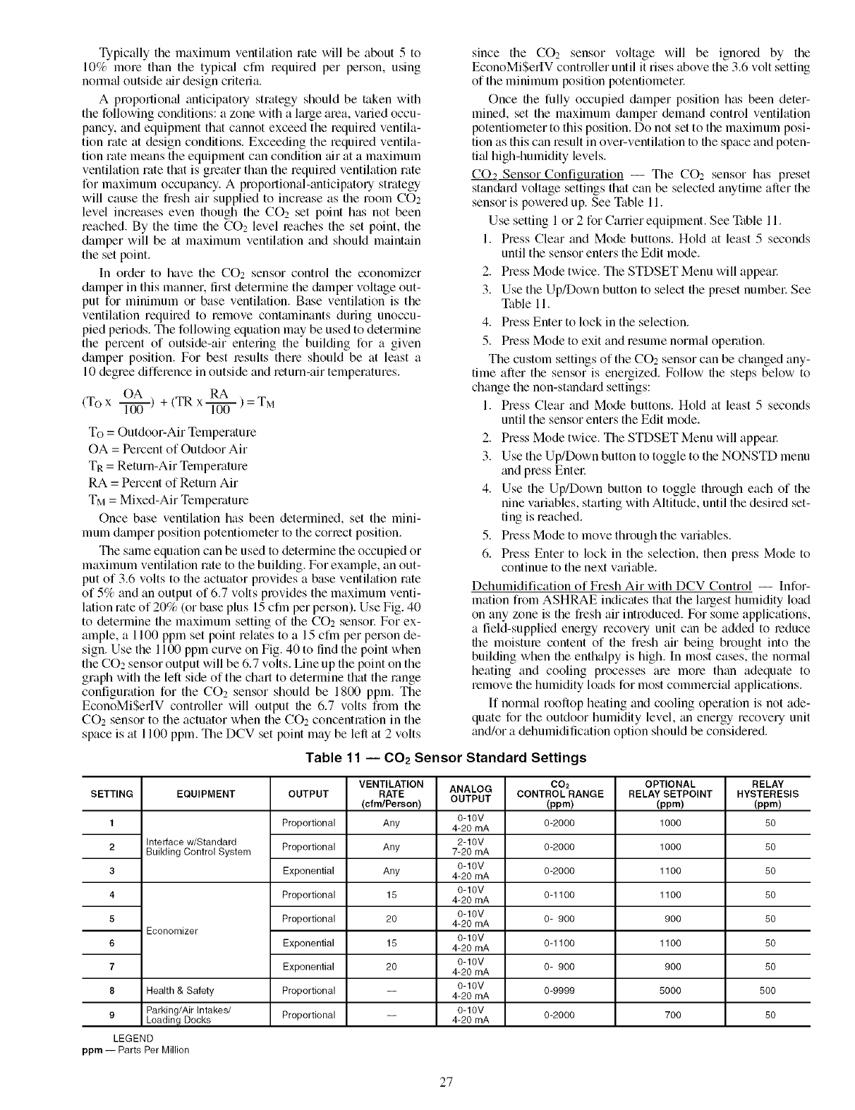
Typicallythe maximum ventilation rate will be about 5 to
10% more than the typical cfm required per person, using
nonnal outside air design criteria.
A proportional anticipato Ustrategy should be token with
the following conditions: a zone with a large area, varied occu-
pancy, and equipment that cannot exceed the requited ventila-
tion rate at design conditions. Exceeding the required ventila-
tion rate means the equipment can condition tfir at a maximum
ventilation rate that is greater than the requited ventilation rate
for maximum occupancy. A propot_tional-anticipatou strategy
will cause the fresh air supplied to increase as the room CO2
level increases even though the CO2 set point has not been
reached. By the time the CO: level teaches the set point, the
damper will be at maximum ventilation and should maintain
the set point.
In order to have the COo_ sensor control the economizer
damper in this manner, first determine the &mper voltage out-
put for minimum or base ventilation. Base ventilation is the
ventilation required to remove contmninants during unoccu-
pied periods. The following equation may be used to determine
the percent of outside-air entering the building for a given
damper position. For best results there should be at least a
10 degree difference in outside and return-air temperatures.
OA RA
(To x l---ff_-)+ (TR x _ )= TM
To = Outdoor-Air Temperature
OA = Percent of Outdoor Air
TR = Return-Air Temperature
RA = Percent of Return Air
TM = Mixed-Air Temperature
Once base ventilation has been determined, set the mini-
mum damper position potentiometer to the correct position.
The same equation can be used to determine the occupied or
maximum ventilation rate to the building. For example, an out-
put of 3.6 volts to the actuator provides a base ventilation rate
of 5% and an output of 6.7 volts provides the maximum venti-
lation rate of 20% (or base plus 15 cfm pet person). Use Fig. 40
to determine the maximum setting of the CO: sensot: For ex-
ample, a 1100 ppm set point relates to a 15 cftn per person de-
sign. Use the 1100 ppm curve on Fig. 40 to find the point when
the CO2 sensor output will be 6.7 volts. Line up the point on the
graph with the left side of the chart to determine that the range
configuration for the CO2 sensor should be 1800 ppm. The
EconoMiSerIV controller will output the 6.7 volts from the
CO2 sensor to the actuator when the CO2 concentration in the
space is at 1100 ppm. The DCV set point may be left at 2 volts
since the CO2 sensor voltage will be ignored by the
EconoMi$erIV controller until it rises above the 3.6 volt setting
of the minimum position potentiometer.
Once the fully occupied damper position has been deter-
mined, set the maximum damper demand control ventilation
potentiometer to this position. Do not set to the maximum posi-
tion as this can result in over-ventilation to the space and poten-
tial high-humidity levels.
CO.2 Sensor Configuration -- The CO2 sensor has preset
stan&trd voltage settings that can be selected anytime after the
sensor is powered up. See Table 11.
Use setting 1 or 2 for Carrier equipment. See Table 11.
1. Press Clear and Mode buttons. Hold at least 5 seconds
until the sensor enters the Edit mode.
2. Press Mode twice. The STDSET Menu will appear.
3. Use the Up/Down button to select the preset number. See
Table 11.
4. Press Enter to lock in the selection.
5. Press Mode to exit and resume normal operation.
The custom settings of the CO2 sensor can be changed any-
time after the sensor is energized. Follow the steps below to
change the non-standard settings:
1. Press Clear and Mode buttons. Hold at least 5 seconds
until the sensor enters the Edit mode.
2. Press Mode twice. The STDSET Menu will appeat:
3. Use the Up/Down button to toggle to the NONSTD menu
and press Enter
4. Use the Up/Down button to toggle through each of the
nine variables, starting with Altitude, until the desired set-
ting is reached.
5. Press Mode to move through the variables.
6. Press Enter to lock in the selection, then press Mode to
continue to the next variable.
Dehumidification of Fresh Air with DCV Control -- Infor-
mation fiom ASHRAE indicates that the lmgest humidity load
on any zone is the fresh air introduced. For some applications,
a field-supplied energy recovery unit can be added to reduce
file moisture content of the fresh air being brought into the
building when the enthalpy is high. In most cases, the normal
heating and cooling processes am morn than adequate to
remove file humidity loads for most commemi_fl applications.
If normal rooftop heating and cooling operation is not ade-
quate for the outdoor humidity level, an energy recovery unit
and/or a dehumidification option should be considered.
Table 11 -- 002 Sensor Standard Settings
SETTING EQUIPMENT
1
2 Interface w/Standard
Building Control System
3
4
5
Economizer
6
7
8 Health & Safety
9 Parking/Air Intakes/
Loading Docks
LEGEND
ppm -- Parts Per Million
OUTPUT
Proportional
Proportional
Exponential
Proportional
Proportional
Exponential
Exponential
Proportional
Proportional
VENTILATION
RATE
(cfm/Pereon)
Any
Any
Any
15
20
15
20
ANALOG
OUTPUT
0-10V
4-20 mA
2-10V
7-20 mA
0-10V
4-20 mA
0-10V
4-20 mA
0-10V
4-20 mA
0-10V
4-20 mA
0-10V
4-20 mA
0-10V
4-20 mA
0-10V
4-20 mA
CO2
CONTROLRANGE
(ppm)
0-2000
0-2000
0-2000
0-1100
0- 900
0-1100
0- 900
0-9999
0-2000
OPTIONAL
RELAY SETPOINT
(ppm)
1000
1000
1100
1100
900
1100
900
5000
7OO
RELAY
HYSTERESIS
(pprn)
5O
5O
5O
5O
5O
5O
5O
5OO
5O
27
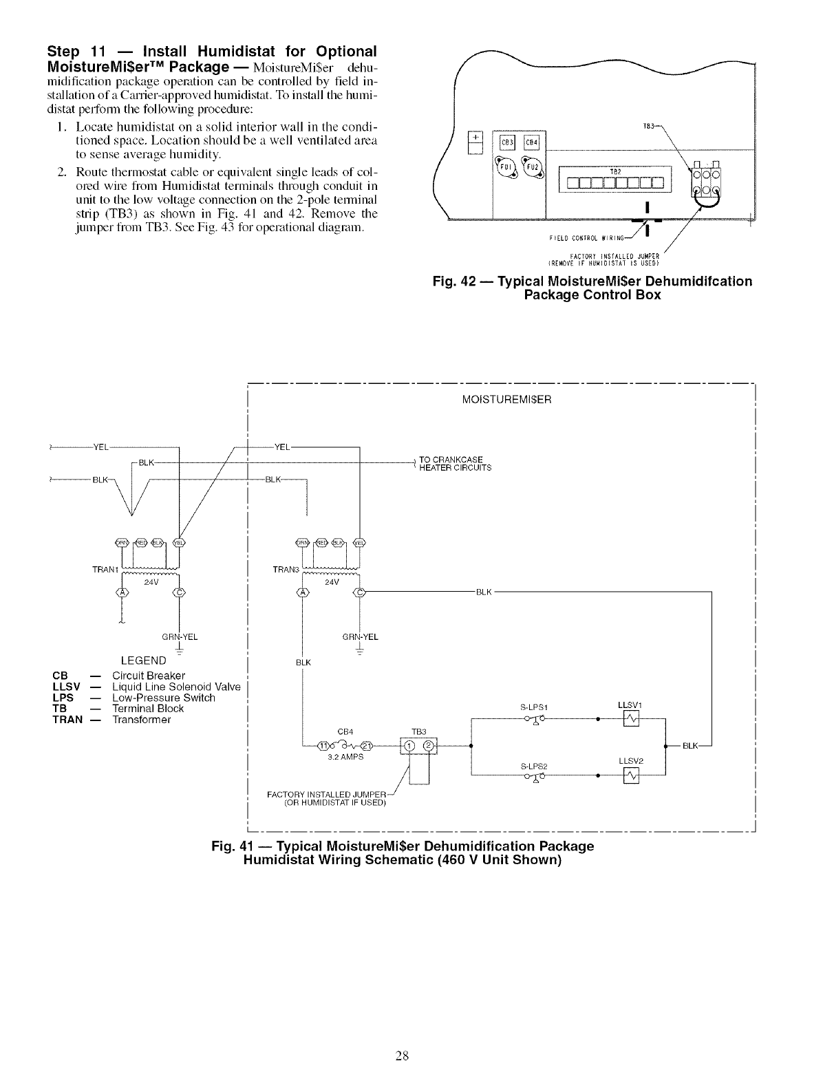
Step 11 -- Install Humidistat for Optional
MoistureMi$er TM Package-- MoistureMiSer dehu-
midification package operation can be controlled by field in-
st;dlation ofa Canier-approved humidistat, To install the humi-
distat perform the following procedure:
1, Locate humidistat on a solid interior wall in the condi-
tioned space. Location should be a well ventilated area
to sense average humidity.
2, Route thermostat cable or equivalent single leads of col-
oled wire from Humidistat termimds through conduit in
unit to the low voltage connection on the 2-pole terminal
strip (TB3) as shown in Fig, 41 and 42, Remove the
jumper from TB3, See Fig. 43 for operational diagram.
Fig. 42 -- Typical MoistureMi$er Dehumidifcation
Package Control Box
MOISTUREMI$ER
_'_YEL-
BLK
BLK_
CB --
LLSV --
LPS --
TB --
TRAN --
YEL.
i
/
TRAN_
GRN YEL
J
LEGEND
Circuit Breaker
Liquid Line Solenoid Valve
LowPressure Switch
Terminal Block
Transformer
TRAN
24V
GRN YEL
TO CRANKCASE
/ HEATER CIRCUITS
BLK
BLK
S LPS1 8 LLSVLsw2_
BLK--
3 2AMPS _ L S_SLPS2 • L
FACTORY INSTALLED JUMPER
(OR HUMIDISTAT IF USED)
Fig. 41 -- Typical MoistureMi$er Dehumidification Package
Humidistat Wiring Schematic (460 V Unit Shown)
28
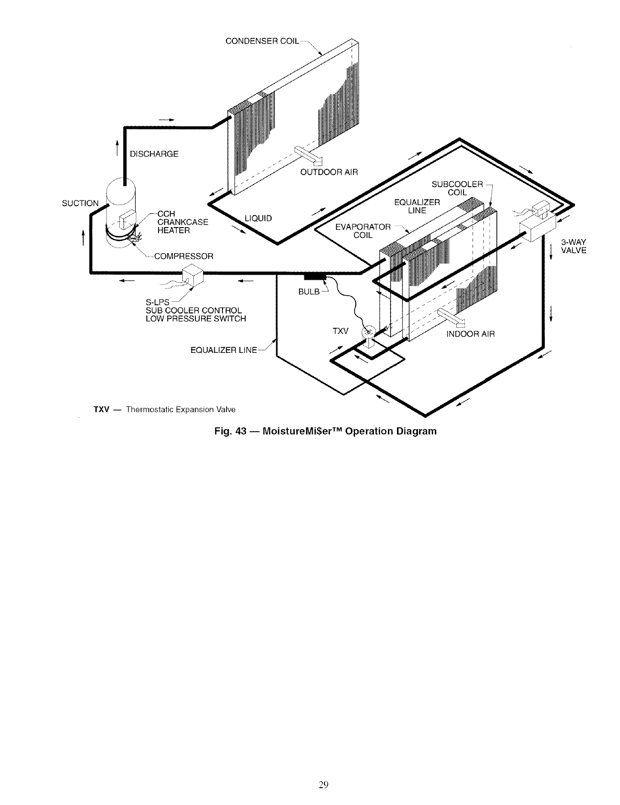
CONDENSER COIL ,
SUCTION
l DISCHARGE
p-CCH
J CRANKCASE LIQUID
HEATER
\°COMPRESSOR
OUTDOORAIR
EVAPORATOR
COIL
EQUALIZER
LINE
COIL
3-WAY
VALVE
S-LPS _
SUB COOLER CONTROL
LOW PRESSURE SWITCH
EQL
TXV INDOOR AIR
TXV -- Thermostatic Expansion Valve
Fig. 43 -- MoistureMi$er TM Operation Diagram
29
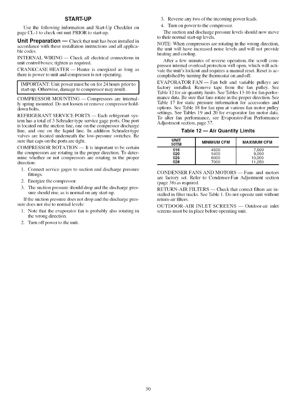
START-UP
Use the following information and St_ut-Up Checklist on
page CL-I to check out unit PRIOR to start-up.
Unit Preparation -- Check that unit has been installed in
accordance with these installation instructions and all applica-
ble codes.
INTERNAL WIRING -- Check all electric;d connections in
unit control boxes; tighten as required.
CRANKCASE HEATER--Heater is energized as long as
there is power to unit and compressor is not operating.
IMPORTANT: Unit power must be on for 24 hom_ prior to ]
start-up. Otherwise, dmnage to compressor may result. I
COMPRESSOR MOUNTING -- Compressors are intern_d-
ly spring mounted. Do not loosen or remove compressor hold-
down bolts.
REFRIGERANT SERVICE PORTS -- Each refrigerant sys-
tem has a total of 3 Schrader-type service gage ports. One port
is located on the suction line, one on the complessor discharge
line, and one on the liquid line. In addition Schmder-type
v_dves are located underneath the low-plessure switches. Be
sure that caps on the ports are tight.
COMPRESSOR ROTATION -- It is important to be certain
the compressors are rotating in the proper direction. To deter-
mine whether or not compressors tue rotating in the proper
direction:
1. Connect service gages to suction and discharge pressure
fittings.
2. Energize the compressol:
3. The suction pressure should drop and the discharge pres-
sure should rise, as is normal on any start-up.
If the suction pressme does not drop and the discharge pres-
sure does not rise to normal levels:
1. Note that the evaporator fan is probably _dso rotating in
the wrong direction.
2. Turn off power to the unit.
3. Reverse any two of the incoming power leads.
4. Turn on power to the compmssoc
The suction and discharge pressure levels should now move
to their normal start-up levels.
NOTE: When compressors are rotating in the wrong direction,
the unit will have increased noise levels and will not provide
heating and cooling.
After a few minutes of reverse operation, the scroll com-
pressor internal overload protection will open, which will acti-
vate the unit's lockout and requires a manual reset. Reset is ac-
complished by turning the thermostat on and off.
EVAPORATOR FAN- Fan belt and variable pulleys are
factory installed. Remove tape from the fan pulley. See
Table 12 for air quantity limits. See Tables 13-16 for fan perfor-
mance data. Be sure that rims rotate in the proper direction. See
Table 17 for static pressure information for accessories and
options. See Table 18 for fan rpm at various fan motor pulley
settings. See Tables 19 and 20 for evaporator fan motor data.
To alter fan performance, see Evaporator-Fan Performance
Adjustment section, page 37.
Table 12 -- Air Quantity Limits
UNIT MINIMUM CFM MAXIMUM CFM
50TM
016 4500 7,500
020 5400 9,000
025 6000 10,000
028 7000 11,250
CONDENSER FANS AND MOTORS -- Fans and motors
are factory set. Refer to Condenser-Fan Adjustment section
(page 38) as required.
RETURN-AIR FILTERS -- Check that correct filtel_ are in-
stalled in filter tracks. See Table 1. Do not operate unit without
return-air filters.
OUTDOOR-AIR INLET SCREENS -- Outdoor-air inlet
screens must be in place before operating unit.
3O
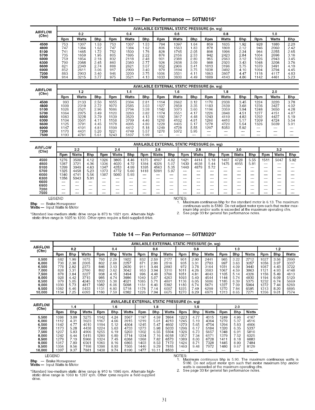
Table 13 -- Fan Performance -- 50TM016*
AIRFLOW
(Cfm)
4500
4800
5100
5700
6000
6300
6600
6900
7200
7500
AVAILABLE EXTERNAL STATIC PRESSURE (in, wg)
0.2 0.4 0.6 0,8 1.0
Rpm Watts Bhp Rpm Watts Bhp Rpm Watts Bhp Rpm Watts Bhp Rpm Watts Bhp
753 1307 1,53 753
747 1384 1,62 747
741 1465 1,72 752
735 1659 1,95 805
759 1854 2,18 832
790 2088 2.45 860
821 2340 2.74 888
852 2611 3.06 917
883 2903 3,40 946
914 3215 3,77 975
1307 1.53 784
1384 1.62 806
1500 1.76 828
1895 2.22 876
2118 2.48 901
2360 2.77 926
2621 3.07 952
2900 3.40 979
3200 3.75 1006
3521 4.13 1033
1397 1,64 859
1563 1,83 878
1745 2,05 898
2156 2,53 942
2388 2,80 965
2638 3.09 988
2906 3,41 1013
3194 3,75 1038
3501 4,11 1063
3830 4,49 1089
1635 1.92 928 1880 2.20
1808 2.12 946 2060 2.42
1996 2.34 964 2255 2.65
2423 2.84 1004 2696 3.16
2663 3.12 1026 2943 3.45
2920 3.43 1048 3208 3.76
3196 3.75 1070 3491 4.10
3492 4.10 1094 3794 4.45
3807 4.47 1118 4117 4.83
4143 4.86 1142 4461 5.23
AIRFLOW
(Cfm)
AVAILABLE EXTERNAL STATIC PRESSURE (in. wg)
1.2 1.4 1.6 1.8 2,0
Rpm Watts Bhp Rpm Watts Bhp Rpm Watts Bhp Rpm Watts Bhp Rpm Watts Bhp
4599 993 2133 2.50 1055 2394 2.81 1114
4809 1009 2319 2.72 1070 2585 3.03 1127
5100 1026 2521 2.96 1086 2794 3.28 1142
5700 1064 2975 3,49 1120 3260 3.82 1174
6000 1083 3228 3,79 1139 3520 4.13 1192
6300 1104 3501 4,11 1158 3799 4.46 1210
6600 1125 3791 4,45 1178 4095 4.80 1229
6900 1147 4101 4,81 1199 4412 5.18 1249
7200 1170 4431 5,20 1221 4749 5.57 1270
7500 1193 4781 5,61 1243 5107 5,99 --
2662 3,12 1170 2938 3.45 1224 3220 3.78
2859 3,35 1183 3139 3.68 1236 3427 4.02
3073 3,60 1196 3359 3.94 1248 3650 4.28
3551 4,17 1226 3848 4.51 1277 4151 4.87
3817 4,48 1243 4119 4.83 1292 4427 5.19
4102 4,81 1260 4410 5.17 1309 4724 5.54
4405 5,17 1278 4720 5.54 1326 5039 5.91
4728 5.55 1297 5050 5.92 -- -- --
5072 5.95 ......
AIRFLOW
(Cfm)
AVAILABLE EXTERNAL STATIC PRESSURE (in. wg)
2,2 2,4 2,6 2.8 3,0 3,2
Rpm Watts Bhp Rpm Watts Bhp Rpm Watts Bhp Rpm Watts Bhp Rpm Watts Bhp Rpm Watts Bhp
4500 1276 3509 4,12 1326 3805 4,46 1375 4107 4,82 1421 4414 5.18 1467 4728 5.55 1511 5047 5.92
4800 1287 3721 4,36 1336 4020 4,72 1384 4326 5,07 1430 4638 5.44 1475 4955 5,81 -- -- --
5100 1299 3949 4.63 1347 4253 4.99 1395 4563 5.35 1440 4879 5.72 ......
6700 1325 4458 5.23 1373 4772 5.60 1418 5091 5.97 .........
6000 1340 4741 5.56 1387 5060 5.93 ............
6300 1356 5043 5.91 ...............
6600 ..................
6900 ..................
7200 ..................
7500 ..................
LEGEND NOTES:
Bhp -- Brake Horsepower 1. Maximum continuous bhp for the standard motor is 6.13. The maximum
Watts-- Input Watts to Motor continuous watts is 5180. Do not adjust motor rpm such that motor max-
imum bhp and/or watts is exceeded at the maximum operating cfm.
*Standard low-medium static drive range is 873 to 1021 rpm. Alternate high- 2. See page 33 for general fan performance notes.
static drive range is 1025 to 1200. Other rpms require a field-supplied drive.
Table 14 -- Fan Performance -- 50TM020*
AIRFLOW
(Cfm)
5,500
6,000
6,500
7,000
7,500
8,000
8,500
9,000
9,500
10,000
AVAILABLE EXTERNAL STATIC PRESSURE (in. wg)
0.2 0,4 0,6 0.8 1,0 1.2
Rpm Bhp Watts Rpm Bhp Watts Rpm Bhp Watts Rpm Bhp Watts Rpm Bhp Watts Rpm Bhp Watts
682 1,99 1675 760 2.29 1922 832 2.59 2177 901 2,90 2441 965 3.22 2712 1027 3.56 2990
730 2,38 2005 802 2.68 2257 871 2.99 2516 935 3,31 2783 997 3.63 3057 1056 3.97 3337
778 2,82 2373 846 3.13 2630 911 3.44 2893 972 3,76 3164 1031 4.09 3440 1087 4.43 3722
828 3,31 2780 892 3.62 3042 953 3.94 3310 1011 4,26 3583 1067 4.59 3863 1121 4.93 4148
878 3,84 3227 938 4.15 3494 996 4.48 3766 1051 4,81 4043 1105 5.14 4326 1156 5.49 4613
928 4,42 3715 985 4.74 3986 1040 5.07 4263 1093 5,40 4544 1144 5.74 4830 1194 6.09 5120
979 5,05 4245 1033 5.38 4521 1085 5.71 4801 1136 6,05 5086 1185 6.39 5375 1232 6.74 5669
1030 5.73 4817 1082 6.06 5098 1131 6.40 5382 1180 6.74 5671 1227 7.09 5964 1272 7.44 6260
1082 6.46 5433 1131 6.80 5718 1178 7.14 6007 1225 7.49 6299 1270 7.84 6595 1313 8.20 6895
1134 7.25 6093 1180 7.59 6382 1226 7.94 6675 1270 8.29 6971 1313 8.65 7271 1356 9.01 7574
AVAILABLE EXTERNAL STATIC PRESSURE (in. wg)
AIRFLOW
(Cfm) 1.4 1.6 1.8 1.9 2.0
Rpm Bhp Watts Rpm Bhp Watts Rpm Bhp Watts Rpm Bhp Watts Rpm Bhp Watts
5,500 1086 3,89 3275 1142 4,24 3567 1197 4,59 3864 1223 4,77 4015 1249 4,96 4167
6,000 1112 4.31 3623 1167 4.66 3915 1219 5.01 4213 1245 5.19 4364 1270 5.37 4516
6,500 1142 4.77 4010 1194 5.12 4304 1245 5.47 4602 1270 5.65 4754 1294 5.83 4906
7,000 1173 5.28 4438 1224 5,63 4733 1273 5.98 5033 1296 6,17 5184 1320 6,35 5337
7,500 1207 5.83 4906 1255 6,19 5203 1302 6,55 5504 1326 6,73 5657 1348 6,91 5810
8,000 1242 6.44 5415 1289 6.80 5714 1334 7.16 6018 1357 7.34 6171 1379 7.52 6325
8,500 1279 7.10 5966 1324 7.45 6268 1368 7.82 6573 1389 8.00 6728 1411 8.18 6883
9,000 1317 7.80 6561 1360 8.16 6865 1403 8.53 7173 1424 8.71 7328 1445 8.90 7484
9,500 1356 8,56 7198 1398 8,93 7505 1440 9,29 7815 1460 9,48 7972 1480 9,67 8129
10,000 1397 9.37 7881 1438 9.74 8190 1477 10.11 8503 ......
LEGEND NOTES:
Bhp -- Brake Horsepower 1. Maximum continuous bhp is 5.90. The maximum continuous watts is
Watts-- Input Watts to Motor 5180. Do not adjust motor rpm such that motor maximum bhp and/or
watts is exceeded at the maximum operating cfm.
*Standard low-medium static drive range is 910 to 1095 rpm. Alternate high- 2. See page 33 for general fan performance notes.
static drive range is 1069 to 1287 rpm. Other rpms require a field-supplied
drive.
3!
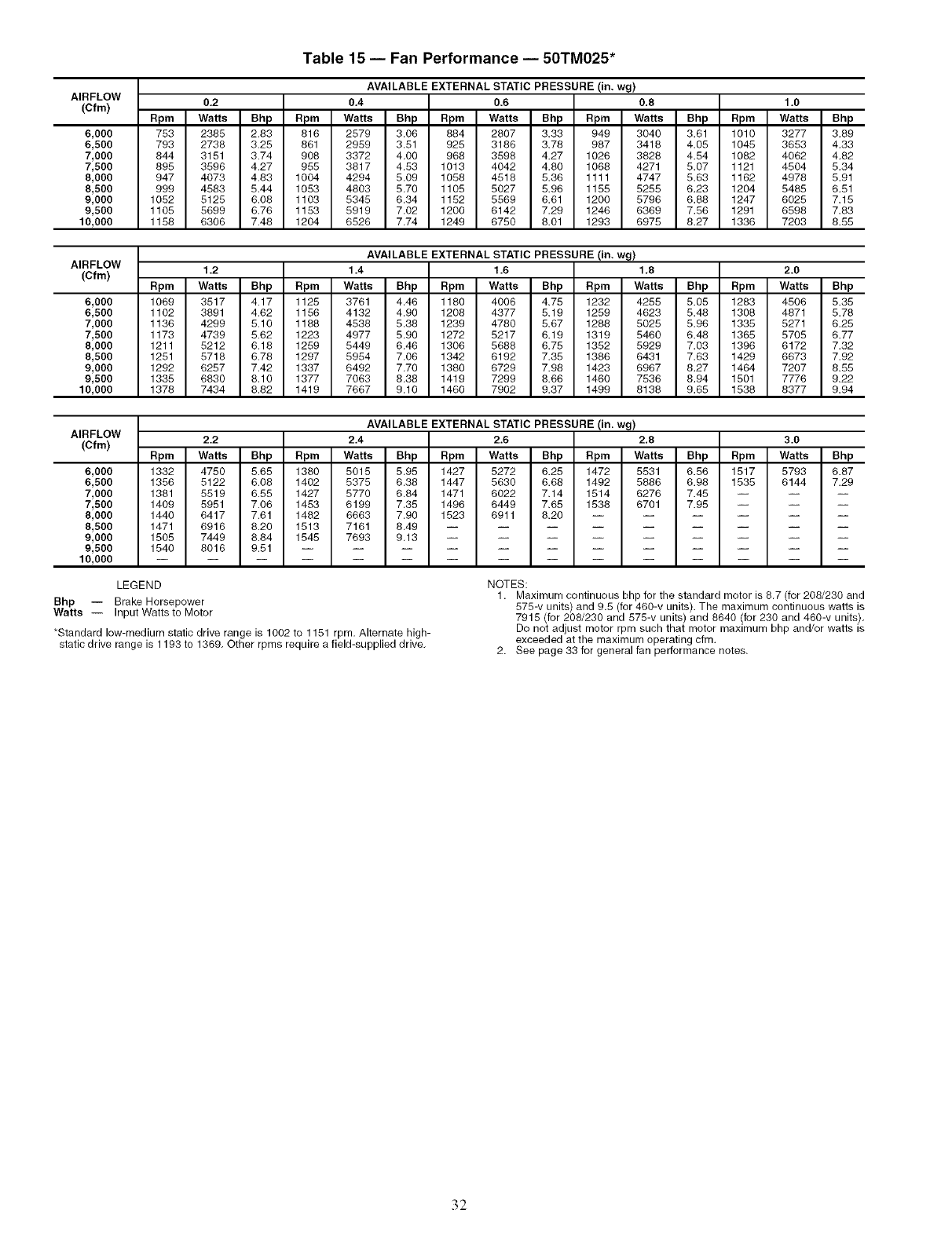
AIRFLOW
(Cfm)
6,000
6,500
7,000
7,500
8,000
8,500
9,000
9,500
10,000
Table 15- Fan Performance- 50TM025"
AVAILABLE EXTERNAL STATIC PRESSURE (in. wg)
0.2 0.4 0.6 0.8 1.0
Rpm Watts Bhp Rpm Watts Bhp Rpm Watts Bhp Rpm Wa_s Bhp Rpm Wat_ Bhp
753 2385 2.83 816 2579 3.06 884 2807 3.33 949 3040 3.61 1010 3277 3.89
793 2738 3.25 861 2959 3.51 925 3186 3.78 987 3418 4.05 1045 3653 4.33
844 3151 3.74 908 3372 4.00 968 3598 4.27 1026 3828 4.54 1082 4062 4.82
895 3596 4.27 955 3817 4.53 1013 4042 4.80 1068 4271 5.07 1121 4504 5.34
947 4073 4.83 1004 4294 5.09 1058 4518 5.36 1111 4747 5.63 1162 4978 5.91
999 4583 5.44 1053 4803 5.70 1105 5027 5.96 1155 5255 6,23 1204 5485 6.51
1052 5125 6.08 1103 5345 6.34 1152 5569 6.61 1200 5796 6.88 1247 6025 7.15
1105 5699 6.76 1153 5919 7.02 1200 6142 7.29 1246 6369 7.56 1291 6598 7.83
1158 6306 7.48 1204 6526 7.74 1249 6750 8.01 1293 6975 8.27 1336 7203 8.55
AIRFLOW
(Cfm)
6,000
6,500
7,000
7,500
8,000
8,500
9,000
9,500
10,000
AVAILABLE EXTERNAL STATIC PRESSURE (in. wg)
1.2 1.4 1.6 1,8 2.0
Rpm Watts Bhp Rpm Watts Bhp Rpm Watts Bhp Rpm Watts Bhp Rpm Watts Bhp
1089 3517 4.17 1125 3761 4.48 1180 4008 4.75 1232 4255 5.05 1283 4506 5.35
1102 3891 4.62 1156 4132 4.90 1208 4377 5.19 1259 4623 5.48 1308 4871 5.78
1136 4299 5.10 1188 4538 5.38 1239 4780 5.87 1288 5025 5.98 1335 5271 6.25
1173 4739 5.62 1223 4977 5.90 1272 5217 8.19 1319 5460 6.48 1365 5705 6.77
1211 5212 8.18 1259 5449 8.48 1308 5888 8.75 1352 5929 7.03 1398 8172 7.32
1251 5718 8.78 1297 5954 7.08 1342 6192 7.35 1386 6431 7.63 1429 8873 7.92
1292 6257 7.42 1337 6492 7.70 1380 6729 7.98 1423 6967 8.27 1464 7207 8.55
1335 6830 8.10 1377 7063 8.38 1419 7299 8.86 1460 7536 8.94 1501 7776 9.22
1378 7434 8.82 1419 7667 9.10 1460 7902 9.37 1499 8138 9.65 1538 8377 9.94
AIRFLOW
(Cfm)
6,000
6,500
7,000
7,500
8,000
8,500
9,000
9,500
10,000
AVAILABLE EXTERNAL STATIC PRESSURE (in. wg)
2.2 2,4 2.6 2,8 3.0
Rpm Wa_s Bhp Rpm Wa_s Bhp Rpm Watts Bhp Rpm Watts Bhp Rpm Watts Bhp
1332 4750 5.85 1380 5015 5.95 1427 5272 8.25 1472 5531 8.56 1517 5793 6.87
1356 5122 8.08 1402 5375 6.38 1447 5630 8.88 1492 5888 8.98 1535 6144 7.29
1381 5519 6.55 1427 5770 6.84 1471 6022 7.14 1514 6276 7.45 -- -- --
1409 5951 7.06 1453 6199 7,35 1496 6449 7.65 1538 6701 7.95 -- -- --
1440 6417 7.61 1482 6663 7.90 1523 6911 8.20 ......
1471 6916 8.20 1513 7161 8.49 .........
1505 7449 8.84 1545 7693 9.13 .........
1540 8016 9.51 ............
LEGEND
Bhp -- Brake Horsepower
Watts -- Input Wattsto Motor
*Standard low-medium static drive range is 1002 to 1151 rpm. Alternate high-
static drive range is 1193 to 1369. Other rpms require a field-supplied drive.
NOTES:
1. Maximum continuous bhp for the standard motor is 8.7 (for 208/230 and
575-v units) and 9.5 (for 460-v units). The maximum continuous watts is
7915 (for 208/230 and 575-v units) and 8640 (for 230 and 460-v units).
Do not adjust motor rpm such that motor maximum bhp and/or watts is
exceeded at the maximum operating cfm.
2. See page 33 for general fan performance notes.
32
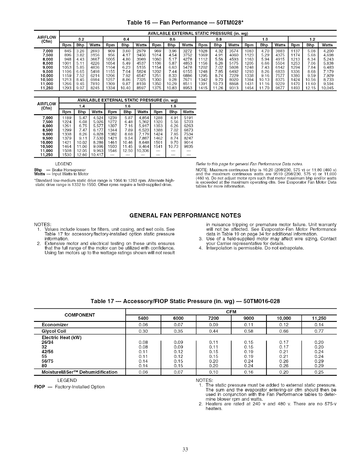
Table 16 -- Fan Performance -- 50TM028"
AIRFLOW
(Cfm)
AVAILABLE EXTERNAL STATIC PRESSURE (in. wg)
0.2 0,4 0,6 0,8 1.0 1.2
Rpm Bhp Watts Rpm Bhp Watts Rpm Bhp Watts Rpm Bhp Watts Rpm Bhp Watts Rpm Bhp Watts
7,000 845 3.26 2693 909 3.60 2979 969 3.96 3272 1028 4.32 3574 1083 4.70 3883 1137 5.08 4,200
7,500 896 3.82 3156 956 4.17 3450 1014 4.54 3752 1069 4.91 4060 1123 5.29 4375 1174 5.68 4,698
8,000 948 4.43 3667 1005 4.80 3969 1060 5.17 4278 1112 5.56 4593 1163 5.94 4915 1213 6.34 5,243
8,500 1001 5.11 4226 1054 5.49 4537 1106 5.87 4853 1156 6.26 5175 1205 6.66 5504 1253 7.06 5,838
9,000 1053 5.85 4836 1104 6.23 5155 1154 6.63 5478 1202 7.02 5808 1248 7.43 6142 1294 7.84 6,483
9,500 1106 6.65 5498 1155 7.04 5824 1202 7.44 6155 1248 7.85 6492 1293 8.26 6833 1336 8.68 7,179
10,000 1159 7.52 6214 1206 7.92 6547 1251 8.33 6886 1295 8.74 7229 1338 9.16 7577 1380 9.59 7,929
10,500 1213 8.45 6984 1257 8.86 7325 1300 9.28 7671 1342 9.70 8020 1384 10.13 8375 1424 10.56 8,733
11,000 1266 9.45 7810 1309 9.87 8159 1350 10.29 8511 1391 10.73 8868 1431 11.16 9229 1470 11.60 9,594
11,250 1293 9.97 8245 1334 10.40 8597 1375 10.83 8953 1415 11,26 9313 1454 11.70 9677 1493 12.15 10,045
AIRFLOW
(Cfm)
7,000
7,500
8,000
8,500
9,000
9,500
10,000
10,500
11,000
11,250
AVAILABLE EXTERNAL STATIC PRESSURE (in. wg)
1.4 1.6 1.8
Rpm Bhp Watts Rpm Bhp Watts Rpm Bhp Watts
1189 5.47 4,524 1239 5.87 4,854 1288 4.91 5191
1224 6,08 5,026 1272 6.48 5,362 1320 5,56 5703
1261 6,75 5,577 1307 7.16 5,917 1353 6,26 6263
1299 7.47 6,177 1344 7.89 6,523 1388 7,02 6873
1338 8.26 6,828 1382 8.68 7,179 1424 7.85 7534
1379 9.11 7,530 1421 9.54 7,887 1462 8,74 8247
1421 10.02 8,286 1461 10,46 8,648 1501 9,70 9014
1464 11.00 9,096 1503 11,45 9,464 1541 10,73 9835
1508 12.05 9,963 1546 12.50 10,336 -- -- --
1530 12.60 10,417 ......
LEGEND
Bhp -- Brake Horsepower
Watts -- Input Watts to Motor
*Standard low-medium static drive range is 1066 to 1283 rpm. Alternate high-
static drive range is 1332 to 1550. Other rpms require a field-supplied drive.
Refer to this page for general Fan Performance Data note&
NOTE: Maximum continuous bhp is 10.20 (208/230, 575 v) or 11.80 (460 v)
and the maximum continuous watts are 9510 (208/230, 575 v) or 11,000
(460 v). Do not adjust motor rpm such that motor maximum bhp and/or watts
is exceeded at the maximum operating cfm. See Evaporator Fan Motor Data
tables for more information.
GENERAL FAN PERFORMANCE NOTES
NOTES:
1. Values include losses for filters, unit casing, and wet coils. See
Table 17 for accessory/factory-installed option static pressure
information.
2. Extensive motor and electrical testing on these units ensures
that the full range of the motor can be utilized with confidence.
Using fan motors up to the wattage ratings shown will not result
in nuisance tripping or premature motor failure. Unit warranty
will not be affected. See Evaporator-Fan Motor Performance
data in Table 19 on page 34 for additional information.
3. Use of a field-supplied motor may affect wire sizing. Contact
your Carrier representative for details.
4. Interpolation is permissible. Do not extrapolate.
Table 17 -- Accessory/FlOP Static Pressure (in. wg) -- 50TM016-028
CFM
7200 9000
Economizer
Glycol Coil
Electric Heat (kW)
26/34
32
42/56
55
56/75
80
MoietureMi$er TM Dehumidification
LEGEND
FlOP -- Factory-Installed Option
COMPONENT 5400 I 6000 10,000 11,250
0.06 J0.07 0.09 0.11 0.12 0.14
0.30 0.35 0.44 0.58 0.66 0.77
0.08 0.09 0.11 0.15 0.17 0.20
0.08 0.09 0.11 0.15 0.17 0.20
0.11 0.12 0.15 0.19 0.21 0.24
0.11 0.12 0.15 0.19 0.21 0.24
0.14 0.15 0.20 0.24 0.26 0.29
0.14 0.15 0.20 0.24 0.26 0.29
0.06 0.07 0.10 0.16 0.20 0.25
NOTES:
1. The static pressure must be added to external static pressure.
The sum and the evaporator entering-air cfm should then be
used in conjunction with the Fan Performance tables to deter-
mine blower rpm and watts.
2. Heaters are rated at 240 v and 480 v. There are no 575-v
heaters.
33
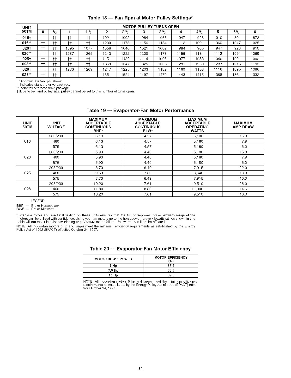
Table 18 -- Fan Rpm at Motor Pulley Settings*
UNIT
50TM 0 16 1 116 2 216
016t tt tt tt tt 1021 1002
016"* tt tt tt tt 1200 1178
020t tt tt 1095 1077 1058 1040
020** tt tt 1287 1265 1243 1222
025t tt tt tt ?t 1151 1132
025** tt tt tt tt 1369 1347
028t tt tt 1283 1269 1247 1225
028** tt tt -- -- 1551 1524
*Approximate _n rpm shown.
tlndicates standard drive package.
**Indicates alternate drive package.
ttDue to belt and pulley size, pulley cannot be set to this number of turns open.
MOTOR PULLEY TURNS OPEN
3316 4 416 5 516 6
984 965 947 928 910 891 873
1156 1134 1112 1091 1069 1047 1025
1021 1002 984 965 947 928 910
1200 1178 1156 1134 1112 1091 1069
1114 1098 1077 1058 1040 1021 1002
1325 1303 1281 1259 1237 1218 1193
1203 1182 1160 1138 1116 1098 1066
1497 1470 1443 1418 1388 1361 1332
Table 19- Evaporator-Fan Motor Performance
UNIT UNIT
50TM VOLTAGE
208/230
016 460
575
208/230
020 460
575
206/230
025 460
575
208/230
028 460
575
LEGEND
BHP -- Brake Horsepower
BkW-- Brake Kilowatts
MAXIMUM MAXIMUM MAXIMUM
ACCEPTABLE ACCEPTABLE ACCEPTABLE MAXIMUM
CONTINUOUS CONTINUOUS OPERATING AMP DRAW
BHP* BkW* WATTS
6.13 4.57 5,180 15.8
6.13 4.57 5,180 7.9
6.13 4.57 5,180 6.0
5.90 4.40 5,180 15.8
5.90 4.40 5,180 7.9
5.90 4.40 5,180 6.0
8.70 6.49 7,915 22.0
9.50 7.08 8,640 13.0
8.70 6.49 7,915 10.0
10.20 7.61 9,510 28.0
11.80 8.80 11,000 14.6
10.20 7.61 9,510 13.0
*Extensive motor and electrical testing on these units ensures that the full horsepower (brake kilowatt) range of the
motors can be utilized with confidence. Using your fan motors up to the horsepower (brake kilowatt) ratings shown in this
table will not result in nuisance tripping or premature motor failure. Unit warranty will not be affected.
NOTE: All indoor-fan motors 5 hp and larger meet the minimum efficiency requirements as established by the Energy
Policy Act of 1992 (EPACT) effective October 24, 1997.
Table 20 -- Evaporator-Fan Motor Efficiency
MOTOR HORSEPOWER MOTOR EFFICIENCY
!%)
5 Hp 87.5
7,5 Hp 88,5
10 Hp 89,5
NOTE: All indoor-fan motors 5 hp and larger meet the minimum efficiency
requirements as established by the Energy Policy Act of 1992 (EPACT) effec-
tive October 24, 1997.
34
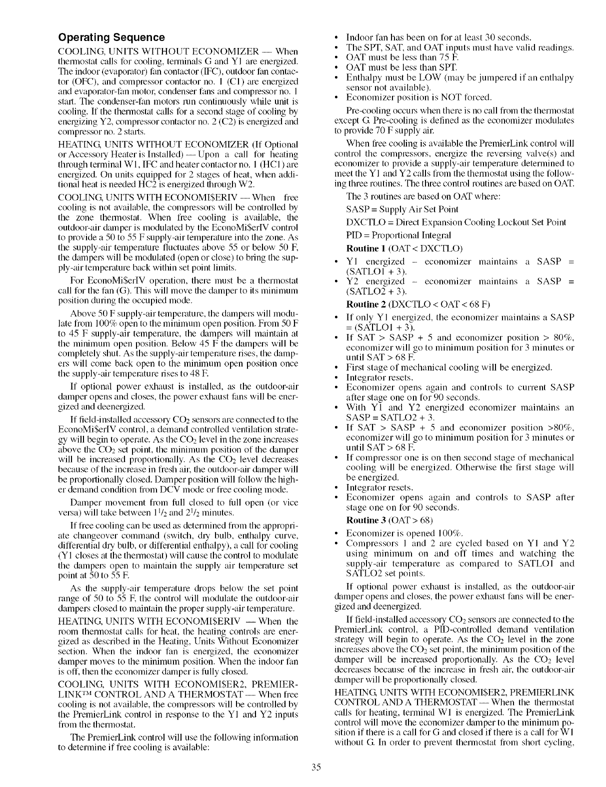
Operating Sequence
COOLING, UNITS WITHOUT ECONOMIZER -- When
thennostat calls for cooling, termimds G and YI ale energized.
The indoor (evaporator) fan contactor (IFC), outdoor fan contac-
tot (OFC), and compressor contactor no. 1 (Ci) m'e energized
and evaporator-fan motol: condenser fans and compressor no. 1
stall. The condenser-fan motors run continuously while unit is
cooling. If the thermostat calls for a second stage of cooling by
energizing Y2, compressor contactor no. 2 (C2) is energized and
compressor no. 2 starts.
HEATING. UNITS WITHOUT ECONOMIZER (If Optional
or Accessory Heater is Installed) --Upon a call for heating
through terminal WI, IFC and heater contactor no. 1 (HCi) are
energized. On units equipped for 2 stages of heat, when addi-
tional heat is needed HC2 is energized through W2.
COOLING. UNITS WITH ECONOMISERIV --When free
cooling is not available, the compressors will be controlled by
the zone thermostat. When free cooling is available, the
outdoor-air &unper is modulated by the EconoMiSerlV control
to provide a 50 to 55 F supply-air temperature into the zone. As
the supply-air temperature fluctuates above 55 or below 50 IF.
the dampel.s will be modulated (()pen or close) to bring the sup-
ply-air temperature back within set point limits.
For EconoMiSerIV operation, there must be a thermostat
call for the fan (G). This will move the damper to its minimum
position during the occupied mode.
Above 50 F supply-air temperature, the dmnpers will modu-
late from 100% open to the minimum open position. From 50 F
to 45 F supply-air temperature, the &_mpers will maintain at
the minimum open position. Below 45 F the dampers will be
completely shut. As the supply-air temperature rises, the damp-
ers will come back open to the minimum open position once
the supply-air temperature rises to 48 E
If optional power exhaust is inst_flled, as the outdoor-air
damper opens and closes, the power exhaust fans will be ener-
gized and deenergized.
If Iield-installed accessory CO2 sensors are connected to the
EconoMiSerIV control, a demand controlled ventilation strate-
gy will begin to operate. As the CO2 level in the zone increases
above the CO2 set point, the minimum position of the &_mper
will be increased proportionally. As the CO2 level decreases
because of the increase in fresh ail: the outdoor-air damper will
be proportionally closed. Dmnper position will follow the high-
er demand condition from DCV mode or free cooling mode.
Damper movement from full closed to lhll open (or vice
vel_a) will take between 11/2and 21/2 minutes.
If free cooling can be used as determined from the appropri-
ate changeover command (switch, diy bulb, enthalpy curve,
differential dry bulb, or differential enthalpy), a call for cooling
(YI closes at the thermostat) will cause the control to modulate
the &tmpel_ open to maintain the supply air temperature set
point at 50 to 55 IF.
As the supply-air temperature diops below the set point
range of 50 to 55 IF.the control will modulate the outdoor-air
dampers closed to maintain the proper supply-air temperature.
HEATING, UNITS WITH ECONOMISERIV -- When the
room thermostat calls for heat, the heating controls are ener-
gized as described in the Heating, Units Without Economizer
section. When the indoor fan is energized, the economizer
damper moves to the minimum position. When the indoor fan
is off. then the economizer dmnper is fully closed.
COOLING. UNITS WITH ECONOMISER2, PREMIER-
LINK TM CONTROL AND A THERMOSTAT -- When free
cooling is not available, the compressol_ will be controlled by
the PremierLink control in response to the YI and Y2 inputs
from the thermostat.
The PremierLink control will use the following information
to determine if free cooling is available:
•Indoor fan has been on for at least 30 seconds.
• The SPT, SAT. and OAT inputs must have valid readings.
• OAT must be less than 75 E
•OAT must be less than SPT.
• Enthalpy must be LOW (may be jumpered if an enthalpy
sensor not available).
•Economizer position is NOT forced.
Pre-cooling occm.s when there is no call from the thermostat
except G Pre-cooling is defined as the economizer modulates
to provide 70 F supply _fil:
When free cooling is available the PremierLink control will
control the compressors, energize the reversing valve(s) and
economizer to provide a supply-air temperature determined to
meet the YI and Y2 calls from the therlnostat using the follow-
ing three routines. The three control routines are based on OAT.
The 3 routines are based on OAT where:
SASP = Supply Air Set Point
DXCTLO = Direct Expansion Cooling Lockout Set Point
PID = Proportional Integral
Routine 1 (OAT < DXCTLO)
• YI energized - economizer maintains a SASP =
(SATLOI + 3).
• Y2 energized - economizer maintains a SASP =
(SATLO2 + 3).
Routine 2 (DXCTLO < OAT < 68 F)
• If only YI energized, the economizer maintains a SASP
= (SATLOI + 3).
• If SAT > SASP + 5 and economizer position > 80%,
economizer will go to minimum position for 3 minutes or
until SAT > 68 E
• First stage of mechanical cooling will be energized.
• Integrator resets.
• Economizer opens again and controls to current SASP
after stage one on for 90 seconds.
• With Yi and Y2 energized economizer maintains an
SASP = SATLO2 + 3.
• If SAT > SASP + 5 and economizer position >80%,
economizer will go to minimum position for 3 minutes or
until SAT > 68 IF.
• If compressor one is on then second stage of mechanical
cooling will be energized. Otherwise the first stage will
be energized.
• Integrator resets.
• Economizer opens again and controls to SASP after
stage one on for 90 seconds.
Routine 3 (OAT > 68)
• Economizer is opened 100%.
• Compressors 1 and 2 are cycled based on YI and Y2
using minimum on and off times and watching the
supply-air temperature as compared to SATLOI and
SATLO2 set points.
If optional power exhaust is installed, as the outdoor-air
&tmper opens and closes, the power exhaust fans will be ener-
gized and deenergized.
If field-installed accessory CO2 sensors me connected to the
PremierLink control, a PlD-controlled demand ventilation
strategy will begin to operate. As the CO2 level in the zone
increases above the CO2 set point, the minimum position of the
&_mper will be increased proportionally. As the CO2 level
decreases because of the increase in fresh air, the outdoor-air
&tmper will be proportionally closed.
HEATING. UNITS WITH ECONOMISER2, PREMIERLINK
CONTROL AND A THERMOSTAT -- When the thermostat
calls for heating, terminal WI is energized. The PremierLink
control will move the economizer damper to the minimum po-
sition if there is a call for G and closed if there is a call for WI
without G. In order to prevent thermostat from short cycling,
35
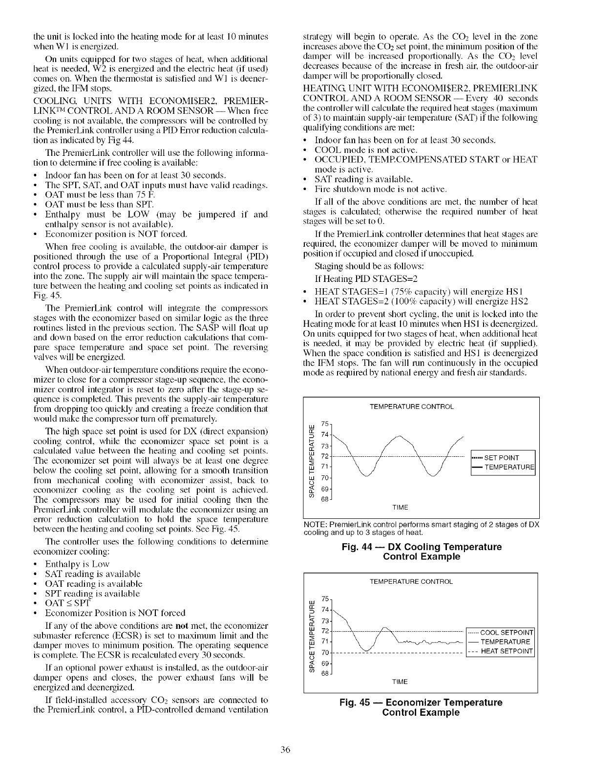
the unit is locked into the heating mode for at least 10 minutes
when WI is energized.
On units equipped for two stages of heat, when additional
heat is needed, W2 is energized and the electric heat (if used)
comes on. When the thermostat is satisfied and WI is deener-
gized, the [FM stops.
COOLING. UNITS WITH ECONOMI$ER2, PREMIER-
LINK TM CONTROL AND A ROOM SENSOR --When free
cooling is not available, the compressors will be controlled by
the PremierLink controller using a PID Error reduction cfdcula-
tion as indicated by Fig 44.
The PremierLink controller will use the following informa-
tion to determine if fiee cooling is available:
• Indoor fan has been on for at least 30 seconds.
• The SPT. SAT. and OAT inputs must have valid readings.
• OAT must be less than 75 E
• OAT must be less than SPT.
• Enthalpy must be LOW (may be jumpered if and
enthalpy sensor is not available).
• Economizer position is NOT forced.
When free cooling is available, the outdoor-air damper is
positioned through the use of a Proportional Integral (PID)
control process to provide a calculated supply-air temperature
into the zone. The supply air will maintain the space tempera-
ture between the heating and cooling set points as indicated in
Fig. 45.
The PlemierLink control will integrate the compressw_
stages with the economizer based on similar logic as the three
routines listed in the previous section. The SASP will float up
and down based on the error reduction calculations that com-
ptue space temperature and space set point. The reversing
vfdves will be energized.
When outdoor-air temperature conditions require the econo-
mizer to close for a compressor stage-up sequence, the econo-
mizer control integrator is reset to zero after the stage-up se-
quence is completed. This plevents the supply-air temperature
from diopping too quickly and creating a freeze condition that
would make the compressor turn off prematurely.
The high space set point is used for DX (direct expansion)
cooling control, while the economizer space set point is a
cfdculated value between the heating and cooling set points.
The economizer set point will always be at least one degree
below the cooling set point, allowing for a smooth transition
from mechanical cooling with economizer assist, back to
economizer cooling as the cooling set point is achieved.
The compressors may be used for initifd cooling then the
PremierLink controller will modulate the economizer using an
error reduction calculation to hold the space temperature
between the heating and cooling set points. See Fig. 45.
The controller uses the following conditions to determine
economizer cooling:
• Enthalpy is Low
• SAT reading is available
• OAT reading is available
• SPT reading is available
• OAT < SPT
• Economizer Position is NOT forced
If any of the above conditions ale not met, the economizer
submaster reference (ECSR) is set to maximum limit and the
dmnper moves to minimum position. The operating sequence
is complete. The ECSR is lecalculated eve U30 seconds.
If an optional power exhaust is instfdled, as the outdoor-air
dmnper opens and closes, the power exhaust fans will be
energized and deenergized.
If field-installed accessory CO2 sensors me connected to
the PlemierLink control, a PID-controlled demand ventilation
strategy will begin to operate. As the CO2 level in the zone
increases above the CO2 set point, the minimum position of the
damper will be increased proportionally. As the CO2 level
decreases because of the increase in fresh all: the outdoor-air
damper will be proportionally closed.
HEATING. UNIT WITH ECONOMISER2, PREMIERLINK
CONTROL AND A ROOM SENSOR -- Every 40 seconds
the controller will cfflculate the required heat stages (maximum
of 3) to mainttfin supply-air temperature (SAT) if the following
qufdifying conditions are met:
• Indoor fan has been on for fit least 30 seconds.
• COOL mode is not active.
• OCCUPIED, TEMRCOMPENSATED START or HEAT
mode is active.
• SAT reading is available.
• Fire shutdown mode is not active.
If all of the above conditions me met, the number of heat
stages is cfflculated; otherwise the required number of heat
stages will be set to 0.
If the PremierLink controller detemfines that heat stages are
required, the economizer damper will be moved to minimum
position if occupied and closed if unoccupied.
Staging should be as follows:
If Heating PID STAGES=2
• HEAT STAGES=I (75% capacity) will energize HSI
• HEAT STAGES=2 (100% capacity) will energize HS2
In order to prevent short cycling, the unit is locked into the
Heating mode for fit least 10 minutes when HS 1 is deenergized.
On units equipped for two stages of heat, when additional heat
is needed, it may be provided by electric heat (if supplied).
When the space condition is satisfied and HSI is deenergized
the IFM stops. The fan will run continuously in the occupied
mode as required by national energy and fresh air standards.
TEMPERATURE CONTROL
w 75,
'_ 734
CE
724-
714
I-
w 704
o
694
CO 68 J
TIME
...... SET POINT
-- TEMPERATURE
NOTE: PremierLink control performs smart staging of 2 stages of DX
cooling and up to 3 stages of heat.
Fig. 44 -- DX Cooling Temperature
Control Example
TEMPERATURECONTROL
D 74
_ 73
72 ......... ....................................F-----coo,SETPO, T
_- 711 \ /I-- TEMPERATURE
ow ii t v L___HEATSETPOINT
TIME
Fig. 45 -- Economizer Temperature
Control Example
36
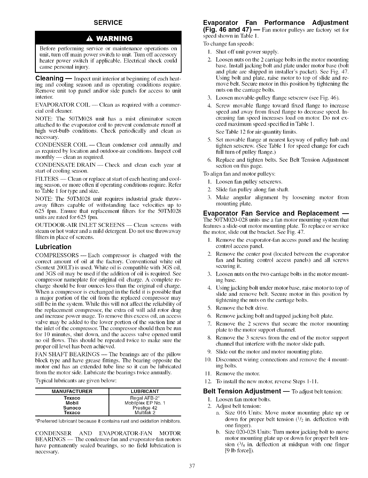
SERVICE
Before performing service or maintenance operations on
unit, turn off main power switch to unit. Tnm off accessory
heater power switch if applicable. Electrical shock could
cause pel.sonal injury.
Cleaning -- Inspect unit interior at beginning of each heat-
ing and cooling season and as operating conditions require.
Remove unit top panel and/or side panels for access to unit
intefiol:
EVAPORATOR COIL -- Clean as required with a commer-
cial coil cleanel;
NOTE: The 50TM028 unit has a mist eliminator screen
attached to the evaporator coil to prevent condensate runoff at
high wet-bulb conditions. Check periodically and clean as
necessmy.
CONDENSER COIL--Clean condenser coil annually and
as required by location and outdoor-air conditions. Inspect coil
monthly -- clean as required.
CONDENSATE DRAIN- Check and clean each year at
start of cooling season.
FILTERS -- Clean or replace at start of each heating and cool-
ing season, or more often if operating conditions require. Refer
to Table 1 for type and size.
NOTE: The 50TM028 unit requires industri_d grade throw-
away filters capable of withstanding face velocities up to
625 fpm. Ensure that replacement filters for the 50TM028
units are rated for 625 fpm.
OUTDOOR-AIR INLET SCREENS -- Clean screens with
steam or hot water and a mild detergent. Do not use throwaway
filters in place of screens.
Lubrication
COMPRESSORS- Each compressor is charged with the
correct amount of oil at the factory. Conventional white oil
(Sontext 200LT) is used. White oil is compatible with 3GS oil,
and 3GS oil may be used if the addition of oil is required. See
compressor nameplate for original oil charge. A complete re-
chmge should be four ounces less than the origimfl oil charge.
When a compressor is exchanged in the field it is possible that
a major portion of the oil from the replaced compressor may
still be in the system. While this will not affect the reliability of
the replacement compressol: the extra oil will add rotor di'ag
and increase power usage. To remove this excess oil, an access
valve may be added to the lower portion of the suction line at
the inlet of the compressol: The compressor should then be mn
for 10 minutes, shut down, and the access valve opened until
no oil fows. This should be repeated twice to make sure the
proper oil level has been achieved.
FAN SHAFT BEARINGS -- The bearings are of the pillow
block type and have grease fittings. The bearing opposite the
motor end has an extended tube line so it can be lubricated
from the motor side. Lubricate the bearings twice annually.
Typical lubricants me given below:
MANUFACTURER LUBRICANT
Texaco Regal AFB-2*
Mobil Mobilplex EP No. 1
Sunoco Prestige 42
Texaco Multifak 2
*Preferred lubricant because it contains rust and oxidation inhibitors.
CONDENSER AND EVAPORATOR-FAN MOTOR
BEARINGS -- The condenser-fan and evaporator-fan motors
have permanently sealed bemings, so no field lubrication is
necesstuy.
Evaporator Fan Performance Adjustment
(Fig. 46 and 47) -- Fan motor pulleys ;u'e factory set for
speed shown in Table 1.
To change fan speeds:
1. Shut offunit power supply.
2. Ix_osen nuts on the 2 cmriage bolts in the motor mounting
base. Install jacking bolt and plate under motor base (bolt
and plate are shipped in inst_fller's packet). See Fig. 47.
Using bolt and plate, raise motor to top of slide and re-
move belt. Secure motor in this position by tightening the
nuts on the carriage bolts.
3. Ix_osen movable-pulley flange setscrew (see Fig. 46).
4. Screw movable flange towmd fixed flange to increase
speed and away from fixed flange to decrease speed. In-
creasing fan speed increases load on motol: Do not ex-
ceed maximum speed specified in Table 1.
See Table 12 for air quantity limits.
5. Set movable flange at nearest keyway of pulley hub and
tighten setscrew. (See Table 1 for speed change for each
lull turn of pulley flange.)
6. Replace and tighten belts. See Belt Tension Adjustment
section on this page.
To align fan and motor pulleys:
1. Ix)osen fan pulley setscrews.
2. Slide fan pulley along fan shaft.
3. Make anguku" alignment by loosening motor from
mounting pkite.
Evaporator Fan Service and Replacement --
The 50TM020-028 units use a fan motor mounting system that
features a slide-out motor mounting pkite. To replace or service
the motor, slide out the bracket. See Fig. 47.
1. Remove the evaporator-fan access panel and the heating
control access panel.
2. Remove the center post (located between the evaporator
fan and heating control access panels) and all screws
securing it.
3. Ix_osen nuts on the two carriage bolts in the motor mount-
ing base.
4. Using jacking bolt under motor base, raise motor to top of
slide and remove belt. Secure motor in this position by
tightening the nuts on the carriage bolts.
5. Remove the belt (hive.
6. Remove jacking bolt and tapped jacking bolt plate.
7. Remove the 2 screws that secure the motor mounting
plate to the motor support channel.
8. Remove the 3 screws from the end of the motor support
channel that interfere with the motor slide path.
9. Slide out the motor and motor mounting pkite.
10. Disconnect wiring connections and remove the 4 mount-
ing bolts.
11. Remove the motol:
12. To install the new motol: reverse Steps 1-11.
Belt Tension Adjustment -- Toadjustbelt tension:
1. Ix_osen fan motor bolts.
2. Adjust belt tension:
a. Size 016 Units: Move motor mounting plate up or
down for proper belt tension (l/z in. deflection with
one finger).
b. Size 020-028 Units: Turn motor jacking bolt to move
motor mounting plate up or down for proper belt ten-
sion (:Vs in. deflection at midspan with one finger
[9 lb force]).
37
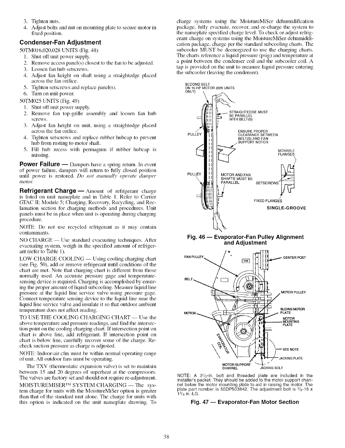
3. Tightennuts.
4. Adjustboltsandnutonmountingplatetosecuremotorin
fixedposition.
Condenser-Fan Adjustment
50TM0I 6,020,028 UNITS (Fig. 48)
1. Shut off unit power supply.
2. Remove access panel(s) closest to the fan to be adjusted.
3. Ix)osen fan hub setscrews.
4. Adjust fan height on shaft using a straightedge placed
across the fan orifice.
5. Tighten setscrews and replace panel(s).
6. Turn on unit powel:
50TM025 UNITS (Fig. 49)
1. Shut off unit power supply.
2. Remove fan top-grille assembly and loosen fan hub
screws.
3. Adjust Nn height on unit, using a straightedge placed
across the fan orifice.
4. Tighten setscrews and replace lubber hubcap to prevent
hub fiom busting to motor shaft.
5. Fill hub recess with permagum if robber hubcap is
missing.
Power Failure -- Dampers have a spring return. In event
of power failure, dampers will return to fully closed position
until power is restored. Do not manually operate damper
1710tOE
Refrigerant Charge -- Amount of refiigerant chalge
is listed on unit nameplate and in Table 1. Refer to C;uTier
GTAC II; Module 5; Charging, Recovery, Recycling, and Rec-
lamation section for charging methods and procedures. Unit
panels must be in place when unit is operating during ch;uging
procedure.
NOTE: Do not use recycled refrigerant as it may contain
contaminants.
NO CHARGE -- Use stan&ud evacuating techniques. After
evacuating system, weigh in the specified amount of refriger-
ant 0efer to Table 1).
LOW CHARGE COOLING -- Using cooling charging chmt
(see Fig. 50), add or remove refrigerant until conditions of the
chart are met. Note that charging chart is different from those
normally used. An accurate pressure gage and temperature-
sensing device is required. Charging is accomplished by ensur-
ing the proper mnount of liquid subcooling. Measure liquid line
pressure at the liquid line service valve using pressure gage.
Connect temperature sensing device to the liquid line near the
liquid line service valve and insulate it so that outdoor ambient
temperature does not affect reading.
TO USE THE COOLING CHARGING CHART -- Use the
above temperature and pressure readings, and find the intersec-
tion point on the cooling charging chart. If intel_ection point on
chart is above line, add refrigerant. If intersection point on
chart is below line, ctuefully recover some of the charge. Re-
check suction pressure as ch;uge is adjusted.
NOTE: Indoor-air cfin must be within normal operating range
of unit. All outdoor fans must be operating.
The TXV (thermostatic expansion v;dve) is set to maintain
between 15 and 20 degrees of superheat at the compressors.
The v;dves abe factory set and should not require re-adjustment.
MOISTUREMISER TM SYSTEM CHARGING -- The sys-
tem charge for units with the MoistureMiSer option is greater
than that of the standard unit alone. The charge for units with
this option is indicated on the unit nameplate drawing. To
chmge systems using the MoistureMiSer dehumidification
package, fully evacuate, recovo: and re-chtuge the system to
the nmneplate specified charge level. To check or adjust refrig-
erant chalge on systems using the MoistureMiSer dehumidifi-
cation package, chtu'ge per the sttm&u'd subcooling ch_u'ts. The
subcooler MUST be deenergized to use the chtuging charts.
The ch_uts reference a liquid pressme (psig) and temperatme at
a point between the condenser coil and the subcooler coil. A
tap is provided on the unit to measure liquid pressure entering
the subcooler (leaving the condenser).
SECOND BELT
ON 10 liP MOTOR (028 UNITS
ONLY)
/
PULLEY
PULLEY
BE PARALLEL
WITR BELT(S)
ENSURE PROPER
CLEARANCE BETWEEN
BELT(S) AND FAN
SUPPORT NOTCH
MOTORANDFAN
SHAFTS MUST BE
PARALLEL
MOVABLE
FLANGES
SETSCREWS_
FIXED FLANGES
SINGLE-GROOVE
Fig. 46- Evaporator-Fan Pulley Alignment
and Adjustment
FAN PULLEY ° CENTER POST
BELT_ MOTOR PULLEY
MOTOR PLATE
R_MOTOR
MOUNTING
PLATE
_o
SEE NOTE
J'M OTO R 2U ppo R_ _l_!r !"1_i'_ TM
CHANNEL JACKING BOLT
NOTE: A 3V2-in. bolt and threaded plate are included in the
installer's packet. They should be added to the motor support chan-
nel below the motor mounting plate to aid in raising the motor. The
plate part number is 50DP503842. The adjustment bolt is 3/8-16 x
13/4 in.-LG.
Fig. 47 -- Evaporator-Fan Motor Section
38
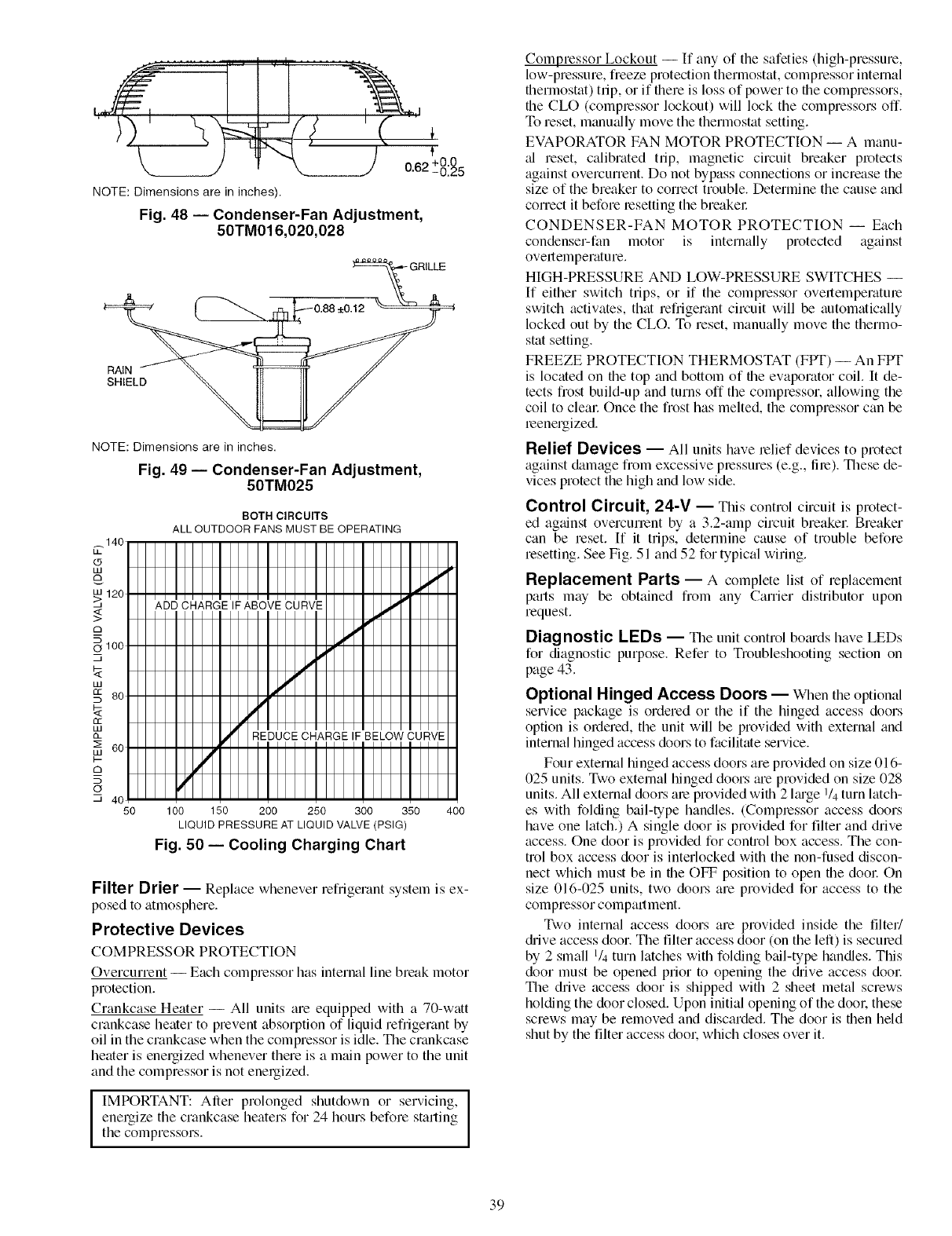
._ r , i ........
t) ) oo +o:o=
NOTE: Dimensions are in inches).
Fig. 48 -- Condenser-Fan Adjustment,
50TM016,020,028
RAIN
SHIELD
NOTE: Dimensions are in inches.
Fig. 49 -- Condenser-Fan Adjustment,
50TM025
BOTH CIRCUITS
ALL OUTDOOR FANS MUST BE OPERATING
50 100 150 200 250 300 350 400
LIQUID PRESSURE AT LIQUID VALVE (PSIG)
Fig. 50 -- Cooling Charging Chart
Filter Drier -- Replace whenever refiigerant system is ex-
posed to atmosphere.
Protective Devices
COMPRESSOR PROTECTION
Overcurrent -- Each compressor has internal line break motor
protection.
Crankcase Heater -- All units are equipped with a 70-watt
crankcase heater to prevent absorption of liquid refrigerant by
oil in the crankcase when the compressor is idle. The crankcase
heater is energized whenever there is a main power to the unit
and the compressor is not energized.
I IMPORTANT: After prolonged shutdown or servicing,
energize the crankcase heaters for 24 hours before starting
the compressors.
Compressor Lockout iIf any of the safeties (high-pressure.
low-pressure, freeze protection thermostat, compressor internal
flierlnostat) trip, or if there is loss of power to the compressors,
die CLO (complessor lockout) will lock the compressors off.
To reset, manually move the therlnostat setting.
EVAPORATOR FAN MOTOR PROTECTION i A manu-
al reset, calibrated trip, magnetic circuit breaker protects
against overcurrent. Do not bypass connections or increase the
size of the breaker to correct trouble. Determine the cause and
correct it before lesetting the breakel:
CONDENSER-FAN MOTOR PROTECTION -- Each
condenser-fan motor is internally protected against
overtemperature.
HIGH-PRESSURE AND LOW-PRESSURE SWITCHES --
If either switch trips, or if the compressor overtemperatule
switch activates, that refrigerant circuit will be automatically
locked out by the CLO. To reset, manually move the thermo-
stat setting.
FREEZE PROTECTION THERMOSTAT (FPT) i An FPT
is located on the top and bottom of die evaporator coil. It de-
tects frost build-up and turns off the compressor, allowing the
coil to cleal: Once the frost has melted, the compressor can be
leenergized.
Relief Devices -- All units have relief devices to protect
against damage from excessive plessures (e.g., fire). These de-
vices protect the high and low side.
Control Circuit, 24-V -- This control circuit is protect-
ed against overcunent by a 3.2-amp circuit breaker Breaker
can be reset. [f it trips, determine cause of trouble before
resetting. See Fig. 51 and 52 for typical wiring.
Replacement Parts -- A complete list of replacement
parts may be obtained from any Carrier distributor upon
request.
Diagnostic LEDs -- qn_e unit control bomds have LEDs
for diagnostic purpose. Refer to Troubleshooting section on
page 43.
Optional Hinged Access Doors -- When the optional
service package is ordered or the if the hinged access doors
option is ordered, the unit will be provided with external and
internal hinged access doors to facilitate service.
Four external hinged access doors are provided on size 016-
025 units. Two external hinged doors ;ue provided on size 028
units. All external doors ale provided wifli 2 huge V4 turn hitch-
es with folding bail-type handles. (Complessor access doors
have one hitch.) A single door is provided for filter and drive
access. One door is provided for control box access. The con-
trol box access door is interlocked with the non-fused discon-
nect which must be in the OFF position to open the dool: On
size 016-025 units, two doors are provided for access to the
compressor compartment.
Two internal access doors are provided inside the filter/
diive access door The filter access door (on the left) is secmed
by 2 small 1/4turn latches with folding bail-type handles. This
door must be opened prior to opening the diive access door
The drive access door is shipped with 2 sheet metal screws
holding the door closed. Upon initial opening of the dool: these
screws may be removed and discarded. The door is fllen held
shut by the filter access dook which closes over it.
39
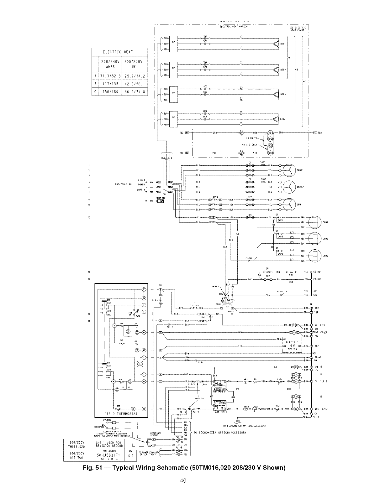
2081230V
TM016.020
2081230V
017 TON
ELECTRIC HEAT
208/240v 200/230V
AMPS KW
A 71.3/823 25.71342
B1171135 42.21561
C 156/180 56,2/74,8
t3
-BL _C_
: -BL
I"
_c_
_BL
, Y[
IHc_
U "
ELECTRIC HEAT OPTION SEE ELECTRIC
HEAT CHARY
/, (B O_LY)_
,{A _ C ONLY)
I I
BL_ at_
SUPPLY" Y[L _L CC_
II I I L°"-_
1 1 ,_ I _ _--_-- _---_'<_-_
BL_ CAP2 y[L_) OFW_
o, :,: ....
m_ ore _, Bt_
_L_ _
_ic_ :LsELECIRTIC _BR_
I B_ BR_ > TRA_
_2
RE_ TO ECONOMIIZR OPIIONIACCgSSORY
..... _'_;_gt ........... Bp_ _. TO ECONOMIZER OPTIONIACCESSORY
-<'I--
REVIS]O.RZCOR_ L __ _ ,_._ |
P^_l _uwB[r _ vlo _vio
50HJ503171 60 oPtmN _ .coy _eL-<<-- _t j
SHY 2OF 3
Fig. 51 -- Typical Wiring Schematic (50TM016,020 208/230 VShown)
4O
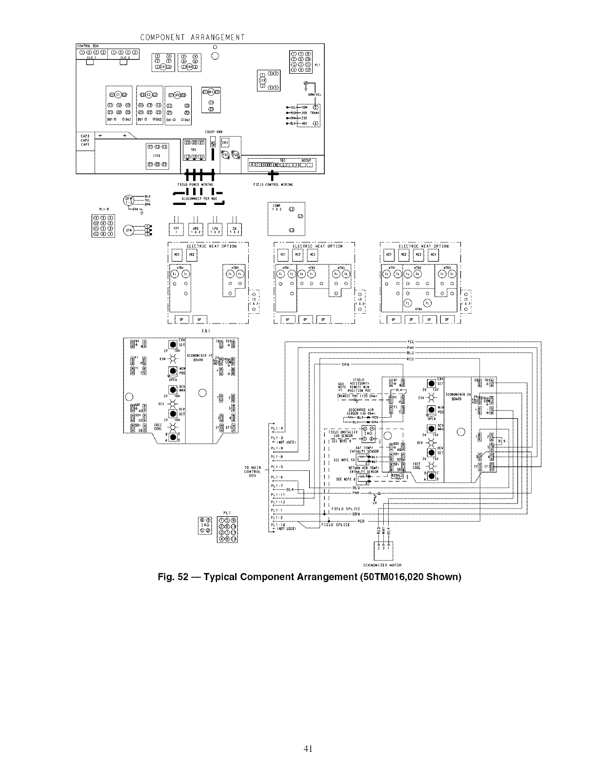
COMPONENT ARRANGEMENT
CONTROLBOX 0
BL_
PL1-R
=
0
_111 I--
OISCONNECTPERHElm _
m m
F _{_cT_T_ci_ 6_,_T_" q
iEO_O i
!;2
LF:_.P,_....... J
{A)
zv 10v
to MAI_
CONYROL
BOX
PLI
F _¢ii_c _- G_Ti_i" q
i° °__o_
LFLI._.FLO .... j
iE]E]E]E]
: o o o o o o o
) o_ -oi
Fig. 52 -- Typical Component Arrangement (50TM016,020 Shown)
41
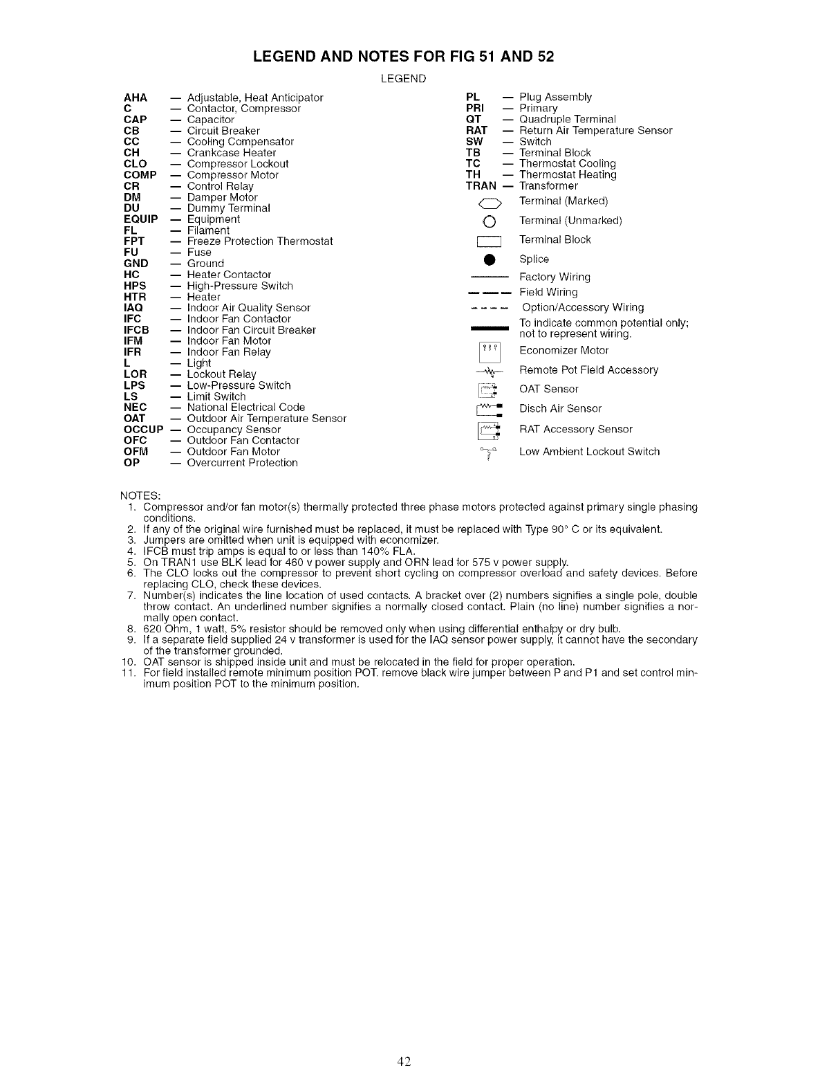
LEGEND AND NOTES FOR FIG 51 AND 52
LEGEND
AHA -- Adjustable, Heat Anticipator PL -- Plug Assembly
C -- Contactor, Compressor PRI -- Primary
CAP -- Capacitor QT -- Quadruple Terminal
CB -- Circuit Breaker RAT -- Return Air Temperature Sensor
CC -- Cooling Compensator SW -- Switch
CH -- Crankcase Heater TB -- Terminal Block
CLO -- Compressor Lockout TC -- Thermostat Cooling
COMP -- Compressor Motor TH -- Thermostat Heating
CR -- Control Relay TRAN -- Transformer
DM -- Damper Motor
DU -- Dummy Terminal Q Terminal (Marked)
EQUIP -- Equipment O Terminal (Unmarked)
FL -- Filament
FPT -- Freeze Protection Thermostat [_ Terminal Block
FU -- Fuse
GND -- Ground • Splice
HC -- Heater Contactor Factory Wiring
HPS -- High-Pressure Switch
HTR -- Heater E mE Field Wiring
IAQ -- Indoor Air Quality Sensor Option/Accessory Wiring
IFC -- Indoor Fan Contactor
IFCB -- Indoor Fan Circuit Breaker _ To indicate common potential only;
IFM -- Indoor Fan Motor not to represent wiring.
IFR -- Indoor Fan Relay Economizer Motor
L -- Light
LOR -- Lockout Relay _ Remote Pot Field Accessory
LPS -- Low-Pressure Switch OAT Sensor
LS -- Limit Switch
NEC -- National Electrical Code _ Disch Air Sensor
OAT -- Outdoor Air Temperature Sensor
OCCUP -- Occupancy Sensor RAT Accessory Sensor
OFC -- Outdoor Fan Contactor
OFM -- Outdoor Fan Motor Low Ambient Lockout Switch
OP -- Overcurrent Protection
NOTES:
1. Compressor and/or fan motor(s) thermally protected three phase motors protected against primary single phasing
conditions.
2. If any of the original wire furnished must be replaced, it must be replaced with Type 90 ° C or its equivalent.
3. Jumpers are omitted when unit is equipped with economizer.
4. IFCB must trip amps is equal to or less than 140% FLA.
5. On TRAN1 use BLK lead for 460 v power supply and ORN lead for 575 v power supply.
6. The CLO locks out the compressor to prevent short cycling on compressor overload and safety devices. Before
replacing CLO, check these devices.
7. Number(s) indicates the line location of used contacts. A bracket over (2) numbers signifies a single pole, double
throw contact. An underlined number signifies a normally closed contact. Plain (no line) number signifies a nor-
mally open contact.
8. 620 Ohm, 1 watt, 5% resistor should be removed only when using differential enthalpy or dry bulb.
9. If a separate field supplied 24 v transformer is used for the IAQ sensor power supply, it cannot have the secondary
of the transformer grounded.
10. OAT sensor is shipped inside unit and must be relocated in the field for proper operation.
11. For field installed remote minimum position POT. remove black wire jumper between P and P1 and set control min-
imum position POT to the minimum position.
42
TROUBLESHOOTING
Unit Troubleshooting -- Refer to Tables 21 and 22 for
troubleshooting details.
EconoMi$erlV Troubleshooting-- See Table 23
for EconoMi$erIV logic.
A fiJnctional view of the EconoMiSer is shown in Fig. 53.
Typical settings, sensor ranges, and jumper positions me also
shown. An EconoMi$erIV simulator program is available flom
Cartier to help with EconoMiSerIV tr;fining and troubleshooting.
ECONOMI$ERIV PREPARATION -- This procedure is
used to prepare the EconoMiSerIV for troubleshooting. No
troubleshooting or testing is done by performing the following
procedure.
NOTE: This procedure requires a 9-v battery. 1.2 kilo-ohm
resistol: and a 5.6 kilo-ohm resistor which are not supplied
with the EconoMiSerlV.
IMPORTANT: Be sure to record the positions of all poten-tiometers before starting troubleshooting.
1. Disconnect power at TR and TRI. All LEDs should be
off. Exhaust fan contacts should be open.
2. Disconnect device at P and Pl.
3. Jumper P to Pl.
4. Disconnect wires at T and TI. Place 5.6 kilo-ohm resistor
across T and TI.
5. Jumper TR to 1.
6. Jumper TR to N.
7. If connected, remove sensor from terminals So and +.
Connect 1.2 kilo-ohm 4074EJM checkout resistor across
terminals So and +.
8. Put 620-ohm resistor across terminals SR and +.
9. Set minimum position, DCV set point, and exhaust
potentiometers fully CCW (counterclockwise).
10. Set DCV maximum position potentiometer fiJlly CW
Iclockwise).
11. Set enthalpy potentiometer to D.
12. Apply power (24 vac) to termimds TR and TRI.
DIFFERENTIAL ENTHALPY-- To check differential
enthalpy:
1. Make sure EconoMiSerIV preparation procedure has
been performed.
2. Place 620-ohm resistor across So and +.
3. Place 1.2 kilo-ohm resistor across SR and +. The Free
Cool LED should be lit.
4. Remove 620-ohm resistor across So and +. The Free
Cool LED should turn off.
5. Return EconoMiSerIV settings and wiring to normal
after completing troubleshooting.
SINGLE ENTHALPY -- To check single enth_dpy:
1. Make sure EconoMiSerIV preparation procedure has
been performed.
2. Set the enthalpy potentiometer to A (fully CCW). The
Free Cool LED should be lit.
3. Set the enthalpy potentiometer to D (fully CW). The Free
Cool LED should turn off.
4. Return EconoMiSerIV settings and wiring to normal
after completing troubleshooting.
DCV (Demand Controlled Ventilation) AND POWER
EXHAUST -- To check DCV and Power Exhaust:
1. Make sure EconoMiSerlV preparation procedure has
been performed.
2. Ensure terminals AQ and AQI are open. The LED for
both DCV and Exhaust should be off. The actuator
should be fully closed.
3. Connect a 9-v battery to AQ (positive node) and AQI
(negative node). The LED for both DCV and Exhaust
should turn on. The actuator should drive to between 90
and 95% open.
4. Turn the Exhaust potentiometer CW until the Exhaust
LED turns off. The LED should turn off when the
potentiometer is approximately 90%. The actuator should
lemain in position.
5. Turn the DCV set point potentiometer CW until the DCV
LED turns off. The DCV LED should turn off when the
potentiometer is approximately 9-v. The actuator should
chive fully closed.
6. Turn the DCV and Exhaust potentiometers CCW until
the Exhaust LED turns on. The exhaust contacts will
close 30 to 120 seconds after the Exhaust LED turns on.
7. Return EconoMiSerlV settings and wiring to normal
after completing troubleshooting.
DCV MINIMUM AND MAXIMUM POSITION -- To check
the DCV minimum and maximum position:
1. Make sure EconoMiSerIV preparation procedure has
been performed.
2. Connect a 9-v battely to AQ (positive node) and AQI
(negative node). The DCV LED should turn on. The
actuator should drive to between 90 and 95% open.
3. Turn the DCV Maximum Position potentiometer to mid-
point. The actuator should drive to between 20 and 80%
open.
4. Turn the DCV Maximum Position potentiometer to fully
CCW. The actuator should drive fully closed.
5. Turn the Minimum Position potentiometer to midpoint.
The actuator should drive to between 20 and 80% open.
6. Turn the Minimum Position Potentiometer fully CW. The
actuator should drive fully open.
7. Remove the jumper from TR and N. The actuator should
&ive fully closed.
8. Return EconoMi$erIV settings and wiring to normal
after completing troubleshooting.
SUPPLY-AIR INPUT -- To check supply-air input:
1. Make sure EconoMiSerlV preparation procedure has
been performed.
2. Set the Enthalpy potentiometer to A. The Free Cool LED
turns on. The actuator should drive to between 20 and
80% open.
3. Remove the 5.6 kilo-ohm resistor and jumper T to TI.
The actuator should drive fully open.
4. Remove the jumper across T and TI. The actuator should
&ive fully closed.
5. Return EconoMiSerIV settings and wiring to normal
after completing troubleshooting.
ECONOMISERIV TROUBLESHOOTING COMPLE-
TION -- This procedure is used to return the EconoMiSerlV
to operation. No troubleshooting or testing is done by perform-
ing the following procedure.
1. Disconnect power at TR and TRI.
2. Set enthalpy potentiometer to previous setting.
3. Set DCV maximum position potentiometer to previous
setting.
4. Set minimum position, DCV set point, and exhaust
potentiometels to previous settings.
5. Remove 620-olun resistor from terminals SR and +.
6. Remove 1.2 kilo-olnn checkout resistor from termimds So
and +. If used, reconnect sensor from temfin_ds So and +.
7. Remove jumper from TR to N.
8. Remove jumper from TR to 1.
9. Remove 5.6 kilo-ohln resistor from T and TI. Reconnect
wires at T and TI.
10. Remove jumper from P to PI. Reconnect device at P and
PI.
11. Apply power (24 vac) to terminals TR and TRI.
43
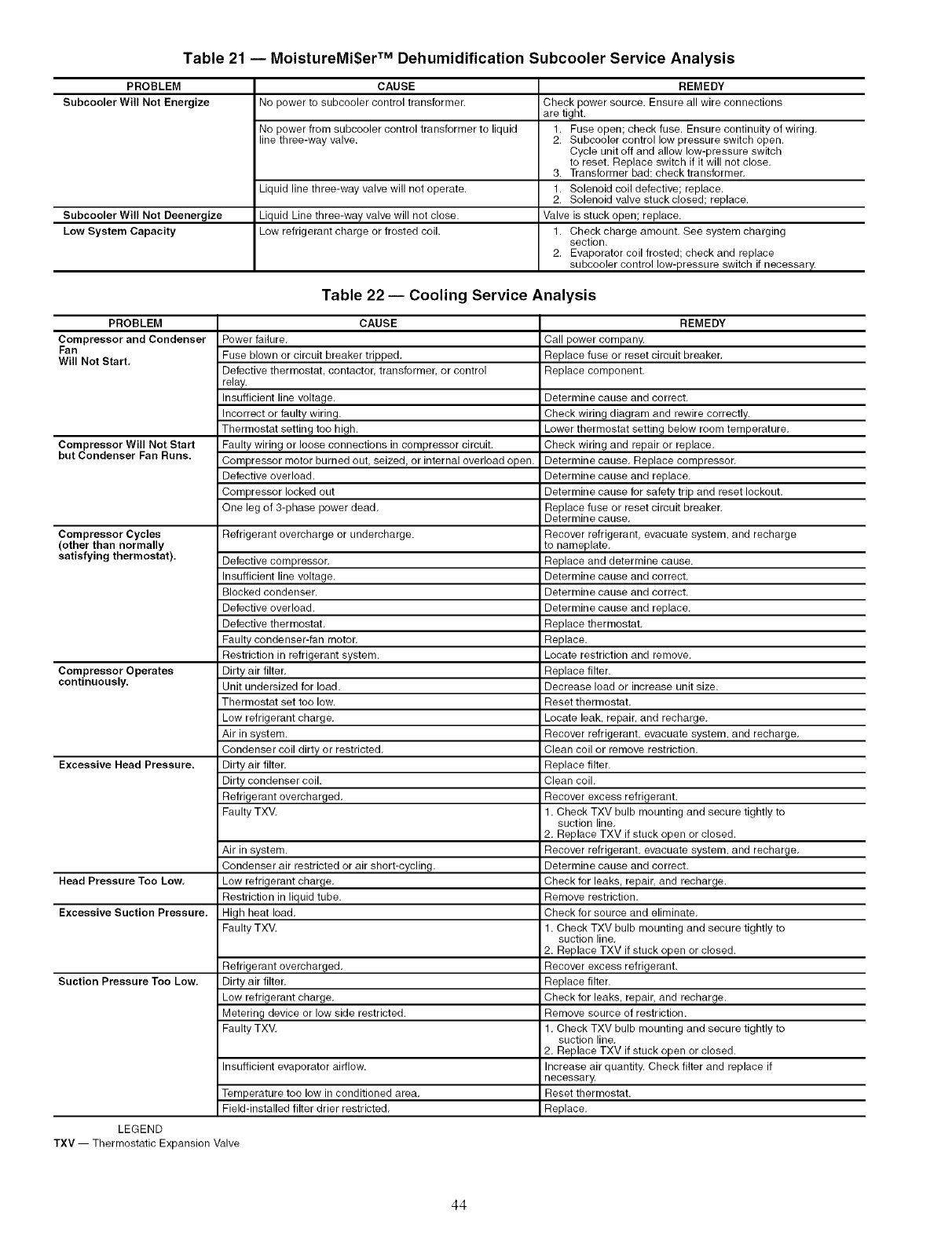
Table 21 -- MoistureMi$er TM Dehumidification Subcooler Service Analysis
PROBLEM
Subcooler Will Not Energize
Subcooler Will Not Deenergize
Low System Capacity
CAUSE
No power to subcooler control transformer.
No power from subceoler control transformer to liquid
line three-way valve.
Liquid line three-way valve will not operate.
Liquid Line three-way valve will not close.
Low refrigerant charge or frosted coil.
REMEDY
Check power source. Ensure all wire connections
are tight.
1. Fuse open; check fuse. Ensure continuity of wiring,
2. Subcooler control low pressure switch open.
Cycle unit off and allow low-pressure switch
to reset. Replace switch if it will not close,
3. Transformer bad; check transformer,
1. Solenoid coil defective; replace.
2. Solenoid valve stuckclosed; replace.
Valve is stuck open; replace.
1. Check charge amount. See system charging
section.
2. Evaporator coil frosted; check and replace
subceeler control low-pressure switch if necessary.
Table 22 -- Cooling Service Analysis
PROBLEM CAUSE REMEDY
Compressor and Condenser Power failure, Call power company.
Fan Fuse blown or circuit breaker tripped, Replace fuse or reset circuit breaker,
Will Not Start, Defective thermostat, contactor, transformer, or control Replace component,
relay.
Insufficient line voltage. Determine cause and correct,
Incorrect or faulty wiring. Check wiring diagram and rewire correctly.
Thermostat setting too high. Lower thermostat setting below room temperature,
Compressor Will Not Start Faulty wiring or loose connections in compressor circuit, Check wiring and repair or replace,
but Condenser Fan Runs. Compressor motor burned out, seized, or internal overload open. Determine cause, Replace compressor,
Defective overload. Determine cause and replace,
Compressor locked out Determine cause for safety trip and reset lockout,
One leg of 3-phase power dead, Replace fuse or reset circuit breaker,
Determine cause,
Compressor Cycles Refrigerant overcharge or undercharge. Recover refrigerant, evacuate system, and recharge
(other than normally to nameplate,
satisfying thermostat). Defective compressor, Replace and determine cause.
Insufficient line voltage. Determine cause and correct,
Blocked condenser. Determine cause and correct,
Defective overload. Determine cause and replace,
Defective thermostat, Replace thermostat,
Faulty condenser-fan motor, Replace,
Restriction in refrigerant system. Locate restriction and remove,
Compressor Operates Dirty air filter, Replace filter.
continuously. Unit undersized for load. Decrease load or increase unit size.
Thermostat set too low. Reset thermostat,
Low refrigerant charge, Locate leak, repair, and recharge,
Air in system. Recover refrigerant, evacuate system, and recharge,
Condenser coil dirty or restricted, Clean coil or remove restriction,
Excessive Head Pressure. Dirty air filter, Replace filter.
Dirty condenser coil. Clean coil,
Refrigerant overcharged, Recover excess refrigerant.
Faulty TXV. 1. Check TXV bulb mounting and secure tightly to
suction line,
2. Replace TXV if stuck open or closed,
Air in system. Recover refrigerant, evacuate system, and recharge,
Condenser air restricted or air short-cycling. Determine cause and correct,
Head Pressure Too Low, Low refrigerant charge, Check for leaks, repair, and recharge.
Restriction in liquid tube. Remove restriction,
Excessive Suction Pressure. High heat load, Check for source and eliminate,
Faulty TXV, 1. Check TXV bulb mounting and secure tightly to
suction line,
2. Replace TXV if stuck open or closed.
Refrigerant overcharged, Recover excess refrigerant.
Suction Pressure Too Low. Dirty air filter, Replace filter.
Low refrigerant charge, Check for leaks, repair, and recharge.
Metering device or low side restricted. Remove source of restriction.
Faulty TXV. 1. Check TXV bulb mounting and secure tightly to
suction line,
2. Replace TXV if stuck open or closed.
Insufficient evaporator airflow. Increase air quantity. Check filter and replace if
necessary,
Temperature too low in conditioned area. Reset thermostat.
Field-installed filter drier restricted. Replace.
LEGEND
TXV -- Thermostatic Expansion Valve
44
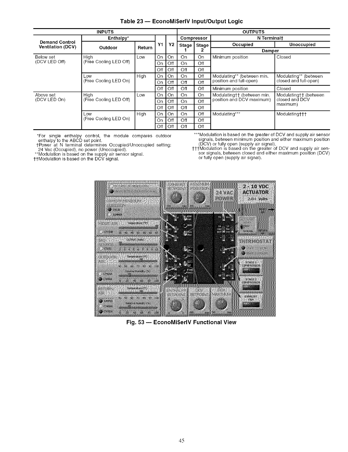
Table 23 -- EconoMi$erlV Input/Output Logic
Demand Control
Ventilation (DCV)
Below set
(DCV LED Off)
Above set
(DCV LED On)
INPUTS
Enthalpy* Compressor
Outdoor Return Y1 Y2 Stage Stage
1 2
High Low On On On On
(Free Cooling LED Off) On Off On Off
Off Off Off Off
Low High On On On Off
(Free Cooling LED On) On Off Off Off
Off Off Off Off
High Low On On On On
(Free Cooling LED Off) On Off On Off
Off Off Off Off
Low High On On On Off
(Free Cooling LED On) On Off Off Off
Off Off Off Off
*For single enthalpy
enthalpy to the ABCD
1-Power at N terminal determines Occupied/Unoccupied
24 Vac (Occupied), no power (Unoccupied).
**Modulation is based on the supply air sensor signal.
ttModulation is based on the DCV signal.
OUTPUTS
N TerminaH-
Occupied Unoccupied
Damper
Minimum position Closed
Modulating** (between min.
3osition and full-open)
Minimum position
Modulatingl-t (between min.
3osition and DCV maximum)
Modulating***
Modulating** (between
closed and full-open)
Closed
Modulatingtl- (between
closed and DCV
maximum)
Modulatingl-l-t
control, the module compares outdoor
set point. setting:
***Modulation is based on the greater of DCV and supply air sensor
signals, between minimum position and either maximum position
(DCV) or fully open (supply air signal).
tttModulation is based on the greater of DCV and supply air sen-
sor signals, between closed and either maximum position (DCV)
or fully open (supply air signal).
Fig. 53 -- EconoMi$erlV Functional View
45
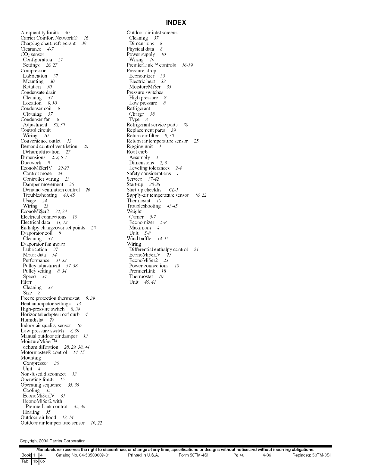
Air quantity limits 30
Carrier Comfort Network0) 16
ChaNingchart, refrigerant 39
Clearance 4-7
CO2 sensor
Configuration 27
Settings 26, 27
Compressor
Lubrication 37
Mounting 30
Rotation 30
Condensate drain
Cleaning .;7
Location 9, 10
Condenser coil 8
Cleaning 37
Condenser fan 8
Adjustment 3& 39
Control circuit
Wiring 10
Convenience outlet 13
Demand control ventilation 26
Dehumidification 27
Dimensions 2, 3, 5-7
Ductwork 9
EconoMi$erIV 22-27
Control mode 24
Controller wiring 23
Damper nlovement 26
Demand ventilation control 26
Troubleshooting 43, 45
Usage 24
Wiring 23
EconoMi$er2 22, 23
Electrical connections 10
Electricaldata 11, 12
Enthalpy changeover set points 25
Evaporator coil 8
Cleaning 37
Evaporator fan motor
Lubrication .;7
Motor data 34
Performance 31-33
Pulley adjustment 3Z .;8
Pulley setting 8, 34
Speed 34
Filter
Cleaning .;7
Size 8
Freeze protection thermostat 8, 39
Heat anticipator settings 13
High-pressure switch 8, 39
Horizontal adapter roof curb 4
Humidistat 28
Indoor air quality sensor 16
Low-pressure switch & .;9
Manual outdoor air damper 13
MoistumMiSer TM
dehumidification 28, 29, 38, 44
Motormasterq_) control 14, 15
Mounting
Compressor 30
Unit 4
Non-fused disconnect 13
Operating limits 15
Operating sequence 35, 36
Cooling 35
EconoMi$erlV 35
EconoMi$er2 with
PremierLink control 3.5,.;6
Heating 35
Outdoor air hood 13, 14
Outdoor air temperature sensor 16, 22
INDEX
Outdoor air inlet screens
Cleaning 37
Dimensions 8
Physical data 8
Power supply 10
Wiring 10
PremierLink TM controls 16-19
Pressure, drop
Economizer 33
Electric heat 33
MoistureMiSer 33
Pressure switches
High pressure 8
Low pressure 8
Refrigerant
Charge 38
Type 8
Refrigerant service ports 30
Replacement parts .;9
Return air filter 8,30
Return air temperature sensor 25
Rigging unit 4
Roof curb
Assembly 1
Dimensions 2, 3
Leveling tolerances 2-4
Safety considerations 1
Service 37-42
Start-up .;0-36
Start-up checklist CL-1
Supply-air temperature sensor 16,22
Thermostat 10
Troubleshooting 43-45
Weight
Corner 5-7
Economizer 5-8
Maximum 4
Unit 5-8
Wind baffle 14,15
Wiring
Differentialenthalpy control 21
EconoMiSerlV 23
EconoMiSer2 23
Power connections 10
PremierLink 18
Thermostat 10
Unit 40, 41
Copyright 2006 Carrier Corporation
Manufacturer reserves the right to discontinue, or change at any time, specifications or designs without notice and without incurring obligations.
Catalog No. 04-53500009-01 Printed in U.S.A. Form 50TM-4SI Pg 46 4-06 Replaces: 50TM-3SI

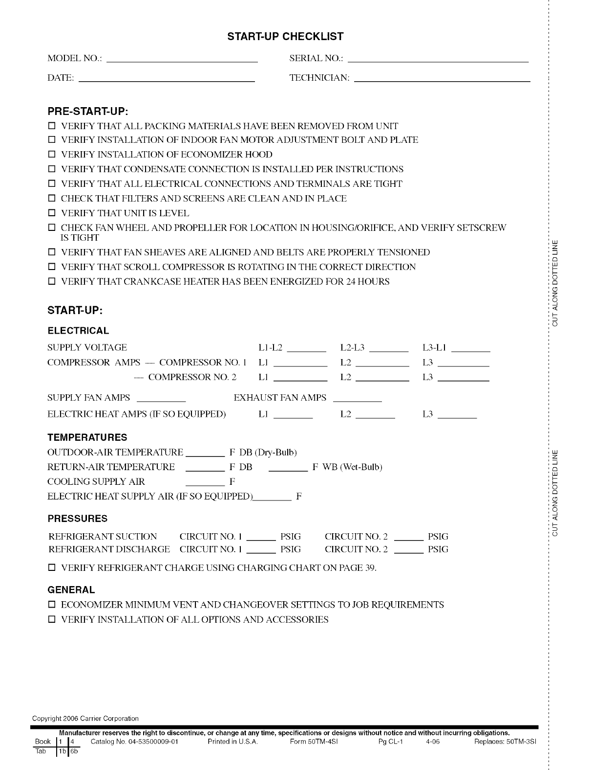
MODEL NO.:
DATE:
START-UP CHECKLIST
SERIAL NO.:
TECHNICIAN:
PRE-START-UP:
[] VERIFY THAT ALL PACKING MATERIALS HAVE BEEN REMOVED FROM UNIT
[] VERIFY INSTALLATION OF INDOOR FAN MOTOR ADJUSTMENT BOLT AND PLATE
[] VERIFY INSTALLATION OF ECONOMIZER HOOD
[] VERIFY THAT CONDENSATE CONNECTION IS INSTALLED PER INSTRUCTIONS
[] VERIFY THAT ALL ELECTRICAL CONNECTIONS AND TERMINALS ARE TIGHT
[] CHECK THAT FILTERS AND SCREENS ARE CLEAN AND IN PLACE
[] VERIFY THAT UNIT IS LEVEL
[] CHECK FAN WHEEL AND PROPELLER FOR LOCATION IN HOUSING/ORIFICE, AND VERIFY SETSCREW
IS TIGHT
[] VERIFY THAT FAN SHEAVES ARE ALIGNED AND BELTS ARE PROPERLY TENSIONED
[] VERIFY THAT SCROLL COMPRESSOR IS ROTATING IN THE CORRECT DIRECTION
[] VERIFY THAT CRANKCASE HEATER HAS BEEN ENERGIZED FOR 24 HOURS
START-UP:
ELECTRICAL
SUPPLY VOLTAGE
COMPRESSOR AMPS -- COMPRESSOR NO. 1
-- COMPRESSOR NO. 2
LI-L2 L2-L3 L3-LI
LI L2 L3
LI L2 L3
SUPPLY FAN AMPS EXHAUST FAN AMPS
ELECTRIC HEAT AMPS (IF SO EQUIPPED) LI L2 L3
TEMPERATU RES
OUTDOOR-AIR TEMPERATURE F DB (Dry-Bulb)
RETURN-AIR TEMPERATURE F DB
COOLING SUPPLY AIR IF
ELECTRIC HEAT SUPPLY AIR (IF SO EQUIPPED)_ F
F WB (Wet-Bulb)
PRESSURES
REFRIGERANT SUCTION CIRCUIT NO. I PSIG CIRCUIT NO. 2
REFRIGERANT DISCHARGE CIRCUIT NO. 1 PSIG CIRCUIT NO. 2
[] VERIFY REFRIGERANT CHARGE USING CHARGING CHART ON PAGE 39.
PSIG
PSIG
GENERAL
[] ECONOMIZER MINIMUM VENT AND CHANGEOVER SETI'INGS TO JOB REQUIREMENTS
[] VERIFY INSTALLATION OF ALL OPTIONS AND ACCESSORIES
Copyright 2006 Carrier Corporation
Manufacturer reserves the right to discontinue, or change at any time, specifications or designs without notice and without incurring obligations.
Book 1 14 Catalog No. 04-53500009-01 Printed in U.S,A. Form 50TM-4SI Pg CL-1 4-06 Replaces: 50TM-3Sl
Tab 1b 16b
LU
z
m
c_
LU
I--
rm
Z
o,
<
I-
o
LU
z
m
rm
LU
I-
c_
Z
o,
<
I-
o
