CARRIER Package Units(both Units Combined) Manual L0703136
User Manual: CARRIER CARRIER Package Units(both units combined) Manual CARRIER Package Units(both units combined) Owner's Manual, CARRIER Package Units(both units combined) installation guides
Open the PDF directly: View PDF ![]() .
.
Page Count: 16
Turn to the Expertg_
Installation Instructions
IMPORTANT: This installation instruction contains basic unit
installation information including installation of field control
devices. For information on unit start-up, service, and operation,
refer to the unit Controls, Start- Up, Operation, Service, and
Troubleshooting Instructions also enclosed in the unit literature
packet.
TABLE OF CONTENTS
SAFETY CONSIDERATIONS ........................ 1
INSTALLATION ................................... 2
Step 1 - Provide Unit Support ...................... 2
Step 2 - Rig and Place Unit ........................ 2
Step 3 - Field Fabricate Ductwork ................... 6
Step 4 - Make Unit Duct Connections ................ 6
Step 5 - Install Flue Hood and Inlet Hood ............. 6
Step 6 - Install External Trap for Condensate Drain ..... 8
Step 7 - Orifice Change ........................... 9
Step 8 - Install Gas Piping ........................ 10
Step 9 - Make Electrical Connections ............... 10
Step 10 - Install Outdoor-Air Hoods (Units with
Economizer ............................ 13
Step 11 - Install All Accessories .................... 13
Step 12 - Configure Controls ...................... 13
SAFETY CONSIDERATIONS
Installation and servicing of air-conditioning equipment can be
hazardous due to system pressure and electrical components.
Only trained and qualified service personnel should install, repair,
or service air-conditioning equipment.
Untrained personnel can perform the basic maintenance functions
of cleaning coils and filters and replacing filters. All other
operations should be performed by trained service personnel.
When working on air-conditioning equipment, observe
precautions in the literature, tags and labels attached to the unit,
and other safety precautions that may apply.
Follow all safety codes. Wear safety glasses and work gloves. Use
quenching cloth for unbrazing operations. Have fire extinguishers
available for all brazing operations.
Recognize safety information. This is the safety-alert symbol
Z_. When you see this symbol on the furnace and in
instructions or manuals, be alert to the potential for personal
injury.
Understand the signal words DANGER, WARNING. and
CAUTION. These words are used with the safety-alert symbol.
DANGER identifies the most serious hazards which win result in
severe personal injury or death. WARNING signifies a hazard
which could result in personal injury or death. CAUTION is used
to identify unsafe practices which may result in minor personal
injury or product and property damage. NOTE is used to
highlight suggestions which will result in enhanced installation.
reliability, or operation.
ELECTRICAL SHOCK HAZARD
Failure to follow this warning could cause personal
injury or death.
Before performing service or maintenance operations
on unit, turn off main power switch to unit and install
lockout tag. Ensure electrical service to rooftop unit
agrees with voltage and amperage listed on the unit
rating plate.
UNIT OPERATION AND SAFETY HAZARD
Failure to follow this warning could cause personal
injury, death and/or equipment damage.
Puron (R-410a) refrigerant systems operate at higher
pressures than standard R-22 systems. Do not use R-22
service equipment or components on Puron refrigerant
equipment.
FIRE,EXPLOSIONHAZARD
Failuretofollowthiswarningcouldresultinpersonal
injury,deathand/orpropertydamage.
Improperinstallation,adjustment,alteration,service,or
maintenancecancausepropertydamage,personal
inju_,orlossof life.RefertotheUser'sInformation
Manualprovidedwiththisunitformoredetails.
Donotstoreorusegasolineorotherflammablevapors
andliquidsinthevicinityofthisoranyotherappliance.
What to do if you smell gas:
1. DO NOT try to light any appliance.
2. DO NOT touch any electrical switch, or use any
phone in your building.
3. IMMEDIATELY call your gas supplier from a
neighbor's phone. Follow the gas supplier's
instructions.
4. If you cannot reach your gas supplier, call the fire
department.
FIRE, EXPLOSION HAZARD
Failure to follow this warning could cause death and/or
property damage.
Disconnect gas piping from unit when leak testing at
pressure greater than 1/2 psig. Pressures greater than 1/2
psig will cause gas valve damage resulting in hazardous
condition. If gas valve is subjected to pressure greater
than 1/2 psig, it must be replaced before use. When
pressure testing field-supplied gas piping at pressures of
1/2 psig or less, a unit connected to such piping must
be isolated by manually closing the gas valve(s).
IMPORTANT: Units have high ambient operating limits. If
limits are exceeded, the units will automatically lock the
compressor out of operation. Manual reset will be required to
restart the compressor.
INSTALLATION
Step 1 --Provide Unit Support
Roof Curb
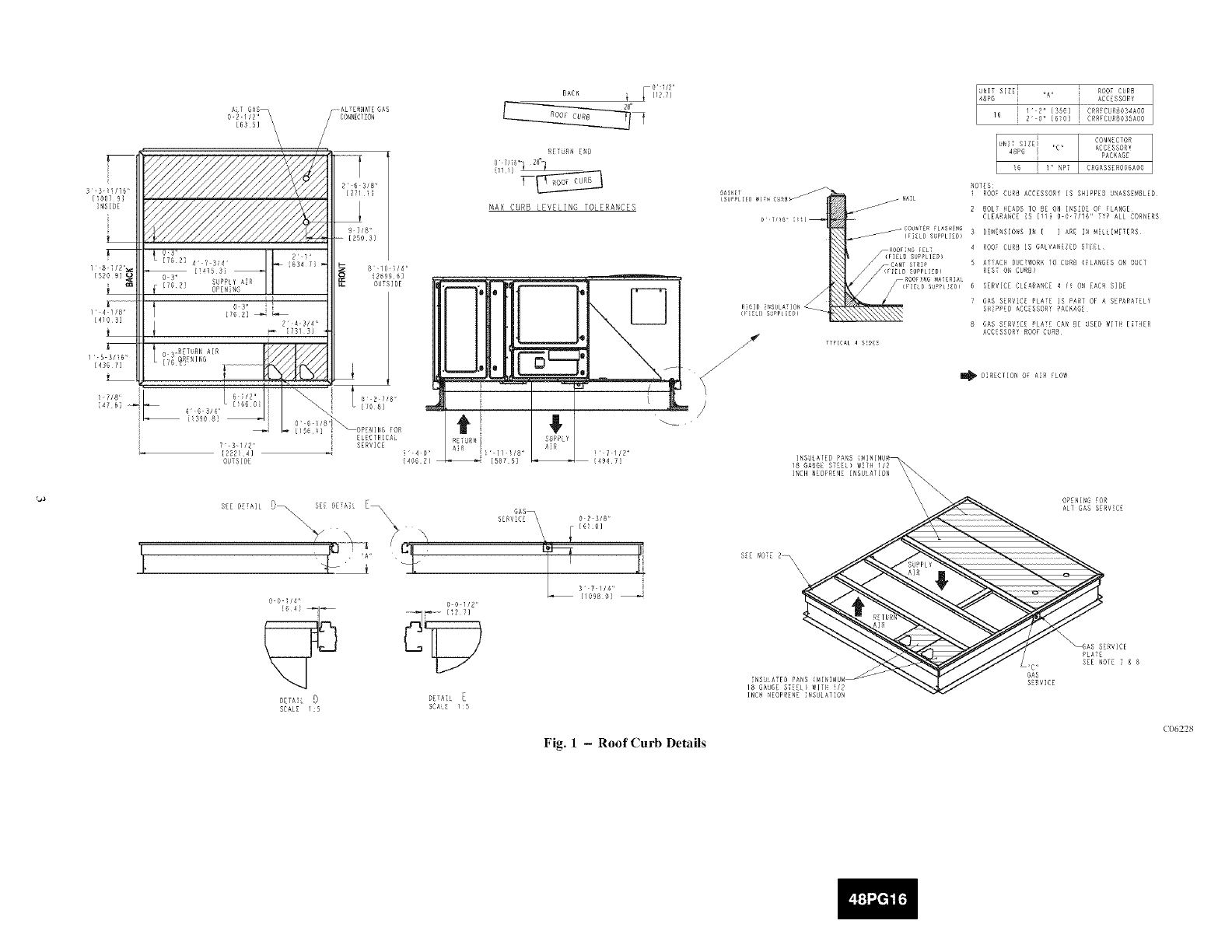
Assemble or install accessory roof curb in accordance with
instructions shipped with this accessory. (See Fig. 1.) Install
insulation, cant strips, roofing, and counter flashing as shown.
Ductwork can be installed to roof curb before unit is set in place.
Ductwork must be attached to curb and not to the unit. Curb must
be level. This is necessary to permit unit drain to function
properly. Unit leveling tolerance is -+1/16 in. per linear ft in an 5,
direction. Refer to Accessory Roof Curb Installation Instructions
for additional information as required. When accessory roof curb
is used, unit may be installed on class A. B, or C roof covering
material. Carrier roof curb accessories are for flat roofs or slab
mounting.
IMPORTANT: The gasketing of the unit to the roof curb is
critical for a watertight seal. Install gasket with the roof curb as
shown in Fig. 1. Improperly applied gasket can also result in air
leaks and poor unit performance. Do not slide unit to position on
roof curb.
Alternate Unit Support
When a curb cannot be used. install unit on a noncombustible
surface. Support unit with sleepers, using unit curb support area.
If sleepers cannot be used. support long sides of unit with a
minimum of 3 equally spaced 4-in. x 4-in. pads on each side.
Step 2 --Rig and Place Unit
Inspect unit for transportation damage. See Table 1 for physical
data. File any claim with transportation agency.
PROPERTY DAMAGE HAZARD
Failure to follow this warning could result in personal
injury, death and property damage.
All panels must be in place when rigging and lifting.
Do not drop unit; keep upright. Use wooden top skid or spreader
bars over unit to prevent sling or cable damage. Rollers may be
used to move unit across a roof. Level by using unit rail as a
reference: leveling tolerance is -+ 1/16 in. per linear fl in any
direction. See Fig. 2 for additional information. Unit rigging
weight is shown in Fig. 2.
Rigging holes are provided in the unit base rails as shown in Fig.
2. Refer to rigging instructions on unit.
Positioning
Maintain clearance, per Fig. 3. around and above unit to provide
minimum distance from combustible materials, proper airflow,
and service access.
Do not install unit in an indoor location. Do not locate air inlets
near exhaust vents or other sources of contaminated air. For
proper unit operation, adequate combustion and ventilation air
must be provided in accordance with Section 5.3 (Air for
Combustion and Ventilation) of the National Fuel Gas Code,
ANSI Z223.1 (American National Standards Institute).
Although unit is weatherproof, guard against water from higher
level runoff and overhangs.
Locate mechanical draft system flue assembly at least 4 ft from
any opening through which combustion products could enter the
building, and at least 4 ft from any adjacent building (or per local
codes). When unit is located adjacent to public walkways, flue
assembly must be at least 7 ft above grade. Locate unit at least 10
ft away from adjacent units.
Roof Mount
Check building codes for weight distribution requirements. Unit
operating weight is shown in Table 1.
AT BASK
[635]
\
:1 i
[]007 91 _
_NSIDE
_ 0 ¸3¸' B I_
[76 2] 4 /3/4 ¸ _ iB34 71 _
[520 9] O S_¸ SUPPLY A_R
_ ITDR} OPENING
/ ¸ 4 I/B '¸ 1
_ 1731 3}
O 6 /8'
L 2
OUTSIDE
810
269
OUT
O 2 7!8
[1081
ELECTRICA_
SERVICE
BACK ]_ _[[127]
RETURN ENB
MAX CURB LEVELING TOLERAS,CES
Tff
OASKEI
{SUPPLIED _IT_ C_RB_
__ RIGID ]NSUL#TIOR
J
J
!-
J
i
/
_ NAL
CO:P,TE R LAS iNG
(r LD S pPLI_O)
_OOr NG FEL
_ FIELO S PLIED
CANT STR P
(F [LD SgPPLi DI
_ ROOFING MAERIA
RETURN i
_4B. AiR i_ ¸- I_ 8 ¸'
i406 Bl [587 B]
}71/B'
[494 7]
UNIT SIZEi ROOF CURB
48PGl'6 i "A" ACCESSOR_
I" 2"_3561 CRRPCURBOS_AOG
2 0" [6_0] CRRECURBOSSAOB
UNiT SIZEi CONNECIOR
48PG i 'C" ACCESSORY
PACKAGE
!6 ! !" NPT CRGASSDRBBBAOO
NOTES
I ROOF CURB ACCESSORY iS SHIPPED UNASSE_DLED
2 BOLT iIEADS TO BE OR INSiB£ OF FLANGE
CLEARANCE IS [_ii g O7116" TYP ALL CORNERS
DIMENSIONS IN [ ] ARE IN M_LLIMETERS
ROOF CURB IS GALVANIZED SIEEi
AiiACR DUCTWORK i0 CBRB (_LANGES ON OUCT
REST ON CURB)
SERVICE CLEARANCE 4F_ ON EACH SIDE
GAS SERVICE RLME IS PAR/ OF _ SEPARA?ELY
S_IPPDD ACCESSORY PACKAGE
GAS SERVICE PLATE CAN BE USED _IT_ EITHER
ACCESSOR_ RODECURB
II_ DIRECTION 0 AiR FLOW
SE BETAiE_
SE DEAIL _\\ \
Oo1/41
DETAIL D
SCALE /:5
o o l/B,,
DEAi
SCALE l:S
O2 3_8'
\W IB_ B]
37 1/_'
[IO98 87
Fig. 1-Roof Curb Details
18 GAUGE STEEL> _IT_ i/B
INCH NEOPRENE INSBiATION
OPDNING FOR
ALT GAS SERVICE
_Eb_BR_ICE
_C' SEE NODE 7 _ B
SERVICE
C06228
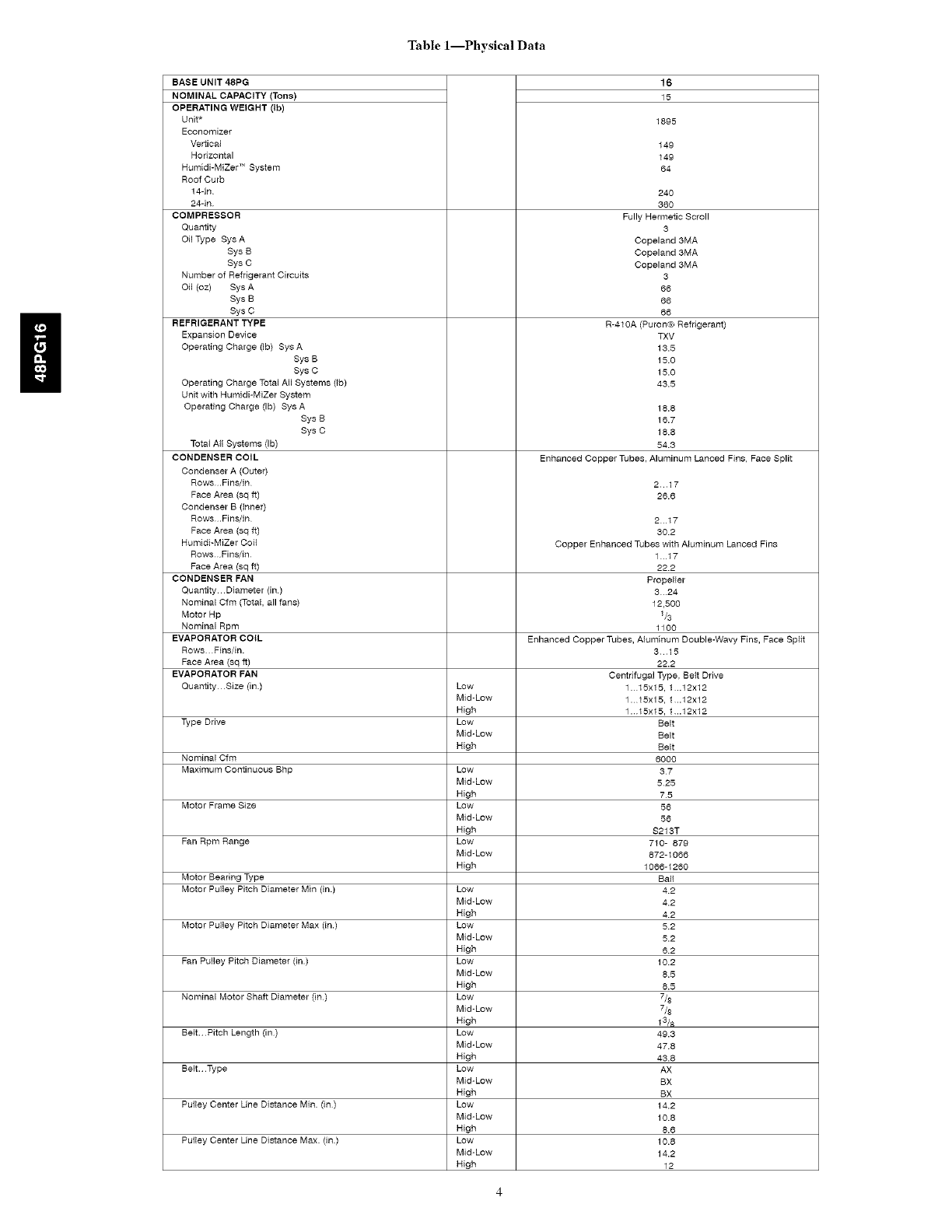
Table l--Physical Data
BASE UNIT 48RG
NOMINAL CAPACITY (Tons)
OPERATING WEIGHT (Ib)
Unit*
Economizer
Ver[ica_
Horizontal
Humidi-MiZer TM System
Roof Curb
14-in
24qn
COMPRESSOR
Quantity
Oil Type Sys A
Sys B
Sys C
Number of Refrigerant Circuits
Oil (oz) Sys A
Sys B
Sys C
REFRIGERANT TYPE
Expansion Device
Operating Charge (Ib) Sys A
Sys B
Sys C
Operating Charge Total All Systems (tb)
Unit with Humidi-MiZer System
Operating Charge (Ib) Sys A
Sys B
Sys C
Total Ati Systems (Ib)
CONDENSER COIL
Condenser A (Outer)
Rows.Fins/in
Face Area (sq ft)
Condenser B (Inner)
Rows.Fins/in
Face Area (sq ft)
HumidFMiZer Coi_
Rows Fins/in
Face Area (sq ft)
CONDENSER FAN
Quantity Diameter (in)
Nominal Cfm {Total, all fans)
Motor Hp
Nominal Rpm
EVAPORATOR COIL
Rows Fins/in.
Face Area (sq ft)
EVAPORATOR FAN
Quantity Size (in)
Type Drive
Nominal Cfm
Maximum Continuous Bhp
Motor Frame Size
Fan Rpm Range
Motor Bearing Type
Motor Pulley Pitch Diameter Min (in.)
Motor Pulley Pitch Diameter Max (in.)
Fan Pulley Pitch Diameter (in.)
Nominal Motor Shaft Diameter (in)
Belt. Pitch Length (in)
Belt. Type
Pulley Center Line Distance Min (in)
Pulley Center Line Distance Max (in)
Low
Mid-Low
High
Low
Mid-Low
High
Low
Mid-Low
High
Low
Mid-Low
High
Low
Mid-Low
High
Low
Mid-Low
High
Low
Mid-Low
High
Low
Mid-Low
High
Low
Mid-Low
High
Low
Mid-Low
High
Low
Mid-Low
High
Low
Mid-Low
High
Low
Mid-Low
High
16
15
1895
149
149
64
Enhanced Copper Tubes, Aluminum Lanced Fins, Face Split
217
28.6
217
30.2
Copper Enhanced Tubes with Atuminum Lanced Fins
1 17
22.2
Propeller
324
12,500
_/3
1100
Enhanced Copper Tubes, A_uminum Double-Wavy Fins, Face Sp_it
315
22.2
Centrifugal Type, Belt Drive
1. 15x15, 1 ..12x12
1. 15x15, 1 ..12x12
1. 15x15, 1 ..12x12
Belt
Belt
Belt
8000
57
525
75
58
56
S215T
7t0- 879
872-1066
1068-1280
Ball
4.2
4.2
4.2
5.2
5.2
6.2
10.2
8.5
8.5
7/8
7/8
t3!_
49.3
47.8
43.8
AX
BX
BX
14.2
18.8
8.6
10.8
14.2
12
TXV
15.5
15.0
15.0
45.5
18.8
18.7
18.8
54.3
24O
36O
Fully Hermetic Scroll
5
Copeland 3MA
Copeland 3MA
Copeland 3MA
3
66
68
66
R-4t 0A (Puron® Refrigerant)
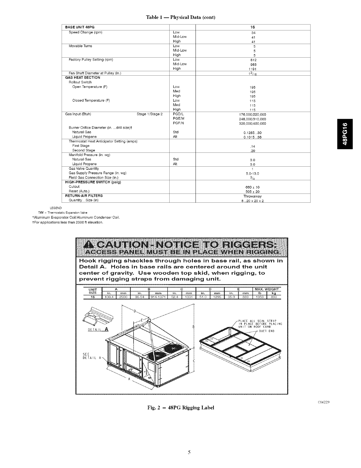
Table 1-- Physical Data (cont)
BASE UNIT 48PG
Speed Change (rpm)
Movab{e Turns
Factory Pulley Setting (rpm)
Fan Shaft Diameter at Rutiey (in.)
GAS HEAT SECTION
Rollout Switch
Open Temperature (F)
Closed Temperature (F)
Gas Input (Btuh) Stage l/Stage 2
Burner Orifice Diameter (in..drill size)t
Natural Gas
Liquid Propane
Thermostat Heat Anticipator Setting (amps)
First Stage
Second Stage
Manifo{d Pressure (in wg)
Natural Gas
Liquid Propane
Gas Valve Quantity
Gas Supply Pressure Range (in wg)
Field Gas Connection Size (in.)
HIGH-PRESSURE SWITCH (psig)
Cutout
Reset (Auto.)
RETURN-AIR FILTERS
Quantity Size (in)
LEGEND
TXV Thermostatic ExpansionValve
*Aluminum Evaporator Coil/Aluminum Condenser Coil.
tFor applications less than 2000 ft elevation.
Low
Mid-Low
High
Low
Mid-Low
High
Low
Mid-Low
High
Low
Med
High
Low
Med
High
PGD/L
PGE/M
PGF/N
16
34
41
41
5
5
5
812
983
1191
13/16
195
195
195
115
115
115
176,000/220,000
248,000/310,000
320,000/400,000
Std 0.1285.30
AIt 0.1015.88
14
20
Std 30
AIt 80
1
5.0-13.0
3/4
660 + 10
505 + 20
Throwaway
8 .20x20x2
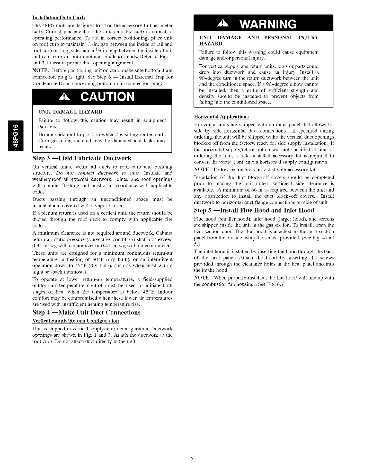
Hook rigging shackles through holes in base rail, as shown in
DetailA. Holes in base rails are centered around the unit
center of gravity. Use wooden top skid, when rigging, to
prevent rigging straps from damaging unit.
UNIT A B C DEMAX, WEIGHT
SIZE in, mm in. mm in, mm in. mm in. mm Ib k_
16 100.4 2550 36 54 914 1371 52.4 1331 5%0 1295 350 889 1959 890
Fig. 2 - 48PG Rigging Label
(;06229
Installation Onto Curb
The 48PG units are designed to fit on the accessory full perimeter
curb. Correct placement of the unit onto the curb is critical to
operating performance. To aid in correct positioning, place unit
on roof curb to maintain 1/4-in. gap between the inside of rail and
roof curb on long sides and a l/2-in, gap between the inside of rail
and roof curb on both duct and condenser ends. Refer to Fig. 1
and 3, to assure proper duct opening alignment.
NOTE: Before positioning unit on curb. make sure bottom drain
connection plug is tight. See Step 6 -- Install External Trap for
Condensate Drain concerning bottom drain connection plug.
UNIT DAMAGE HAZARD
Failure to follow this caution may result in equipment
damage.
Do not slide unit to position when it is sitting on the curb.
Curb gasketing material may be damaged and leaks may
result.
Step 3 --Field Fabricate Ductwork
On vertical units, secure all ducts to roof curb and building
structure. Do not connect ducm'ork to unit. Insulate and
weatherproof all external ductwork, joints, and roof openings
with counter flashing and mastic in accordance with applicable
codes.
Ducts passing through an unconditioned space must be
insulated and covered with a vapor barrier.
If a plenum return is used on a vertical unit, the return should be
ducted through the roof deck to comply with applicable fire
codes.
A minimum clearance is not required around ductwork. Cabinet
return-air static pressure (a negative condition) shall not exceed
0.35 in. wg with economizer or 0.45 in. wg without economizer.
These units are designed for a minimum continuous return-air
temperature in heating of 50°F (dry bulb), or an intermittent
operation down to 45°F (dry bulb), such as when used with a
night set-back thermostat.
To operate at lower return-air temperatures, a field-supplied
outdoor-air temperature control must be used to initiate both
stages of heat when the temperature is below 45°F. Indoor
comfort may be compromised when these lower air temperatures
are used with insufficient heating temperature rise.
Step 4 --Make Unit Duct Connections
Vertical Supply/Return Configuration
Unit is shipped in vertical supply/return configuration. Ductwork
openings are shown in Fig. 1 and 3. Attach the ductwork to the
roof curb. Do not attach duct directly to the unit.
UNIT DAMAGE AND PERSONAL INJURY
HAZARD
Failure to follow this warning could cause equipment
damage and/or personal injury.
For vertical supply and return units, tools or parts could
drop into ductwork and cause an injury. Install a
90-degree turn in the return ductwork between the unit
and the conditioned space. If a 90-degree elbow cannot
be installed, then a grille of sufficient strength and
density should be installed to prevent objects from
falling into the conditioned space.
Horizontal Applications
Horizontal units are shipped with an outer panel that allows for
side by side horizontal duct connections. If specified during
ordering, the unit will be shipped withe the vertical duct openings
blocked off from the factory, ready for side supply installation. If
the horizontal supply/return option was not specified at time of
ordering the unit, a field-installed accessory kit is required to
convert the vertical unit into a horizontal supply configuration.
NOTE: Follow instructions provided with accessory kit.
Installation of the duct block-off covers should be completed
prior to placing the unit unless sufficient side clearance is
available. A minimum of 66 in. is required between the unit and
any obstruction to install the duct block-off covers. Install
ductwork to horizontal duct flange connections on side of unit.
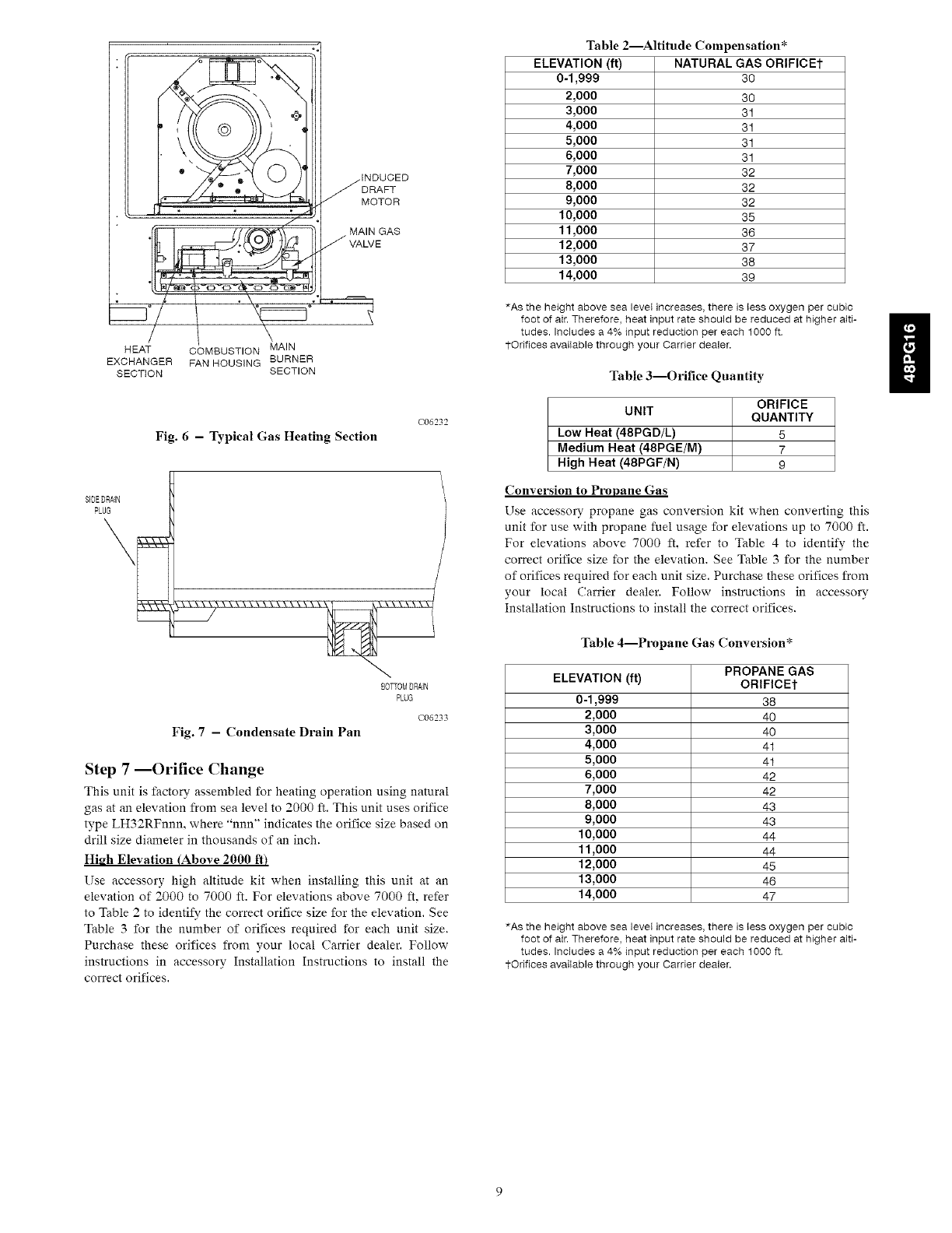
Step 5--Install Flue Hood and Inlet Hood
Flue hood (smaller hood), inlet hood (larger hood), and screens
are shipped inside the unit in the gas section. To install, open the
heat section door. The flue hood is attached to the heat section
panel from the outside using the screws provided. (See Fig. 4 and
5.)
The inlet hood is installed by inserting the hood through the back
of the heat panel. Attach the hood by inserting the screws
provided through the clearance holes in the heat panel and into
the intake hood.
NOTE: When properly installed, the flue hood will line up with
the combustion fan housing. (See Fig. 6.)
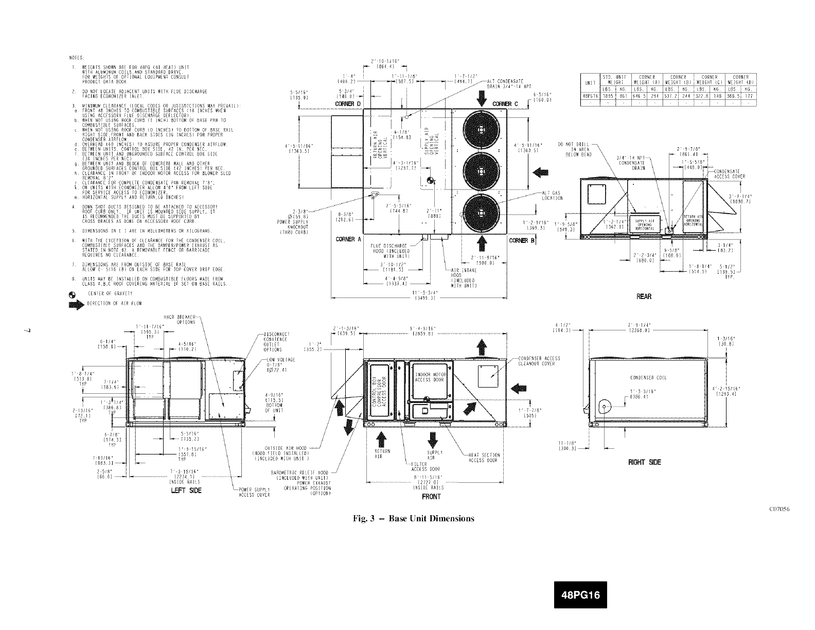
_OIES
I WE:6HTS SHOWN ARE FOR 48PG I_I ilEAT)UN[T
W:TH ALU_[NU_ CO:LSAND STANDARR DRIVE
EOR WRIGHTS OR OPTIONAL [OU:PMEN: ¸ CONSULT
PRODUCT DAIA BOOK
R BO NOT LOCATE ADJACENT UNITS W[TIi ELUE B[SCHARGE
EARING ECO_ONIZER [I_[E:
3 _INIMUN CLSARANCE ([ORAL CODES OR JUSISO[CTIONS MAT PRRVAI])
:RONT 48 INCHES TO CO_RUST:CL_ SURFACES [18 [NC_ES _RN
US:NG ACCESSORY ELD[ RiSCHARGR REFLECTOR)¸
b _HEC ROT USINO ROOf CURB I: I_CH} RO[lO_ OF BASE RAN lO
CO_BUST:B[R RDREACES
_HER NO: USINB ROOF CURB {0 INCHES1 i0 ROTTO_ OF BASE RA:L
R:BRT S:D[FRBNT AND _AC_ SIDES 136 :NCiIESI :OR PROPER
CONDENSER A:RFEOW
d OVERHEAR 160 INCHES)iO ARSUR_ PRORER CONDENSER AIRFLOW
_ REIWREN UN[_S, CONIROL BOX SIDE, 4Z IN PER NEC
[ BETWI:_N UN[i A_B UNOROUNCED SURFACE CONTROL BOX SERE
136 INCHES PER NEC)
g RETW[RN UNIT ANO BROCK BE RBNCRETR _ALI ANR OTHER
GROUN_ER SURFACES CONTROL _OX S:RE 142 INRFRSI PER NEC
_ CLEARANCE IN FRONT OT INDOOR _0iOR ACCESS FOR BLOWER SLED
RfMBVAL 8_ _
: CIRARANC[ fOR CONPLRTE CONDENSATE PAN RR_OVAL 7"8
_ ON UNITS WITH _CONO_[RER AL{BW 4"0" IRO_ LEfl SlOE
EOR SERVICE ACCESS TO ECONOMIZER¸
m IIORIZONTA[ SUPPL¥ AND REtURN,TO INCHES)
4 DOWN SilOT DUCTS RESIGNED TO BR ATTACHE_ TO ACCESSORT
ROOF CRRO ONLY¸ if UNII :S MOUNI[_ SlOE SUPPLY [[
[S RRCOMMRNDED THE _UCIS _USI BE SDPPORIED BY
CROSS BRACES AS RONE ON ACCESSORY ROOF CURB
R D:_ENS:ONS IN I ARE [N _ILI[_ETE£S OR _ILOGRAMS
_ _IIIL T_I[E_CERI:ON OT CLEARANCE FOR :_[ CO_OENSER COIL,
COM_DSTI_IE SURTACRS AND TI4EDAMPER/POWER EXHAUST AS
STATRD IN NOTR _R A REMOVAC[{ FENCE OR _ARR[CADR
REQUIRES NO CleARANCE
f OIMENS:ONS ARE iROM OUISIOE OE CASE RAIL
ALIO_ O ¸ 5/16 [81 ON EACH SlOE FOR tOP COVER DRIP EBGR
8 UNITS _AY BE [NS:AIIED ON CO_B_ST[BLE E[OORS _AR_ IRO_
CLASS A,B,C ROOF COVERING MATERIAL :F SET ON CASE RAILS¸
CENTER O_ GRAVIIT
Im4_I_[RECT[ON OF A[R FIO_
R 5M6"
{135 O]
4" 5 IWl_"
1_363 51
@[59 81
POWRRRUP£17
_NOR_OUT
(THRU CURB}
11 53/4'
134993]
IINCL@E8
WITH UNTil
797/8"
[86141
:" 55/S" I
65/8"
R R 3/4' {168 O}
[6DO 0}
[4480]r- 1: CONBENSAIE
I_ARRERS ROVER
TTR
REAR
6 1/4"
[/586]_
8114"
[513 8] ///_
l'flP {18S 61
i
[380 8]
R/_'f!'3/16'<
6 7/8'
[1_4/173]
7 13//6"
[183 3]_
R RIB"
[5_6]
TYR
:7P
R1R/T6'
[2234 l] .....................
[NSIOE RAILS
LEFT SIDE
BAROMRTRIC REIEIE
(:NCLUDED W:TH UNIT)
POWER _XBAUST
_POWER SUPPLY ORERAIING POS:FION
ACCESS COVER (OPiION)
4 1/2" l 91/4"
£ 4 9/16" {114 7]_ [2568 O]
CONIT{NSER COlE
_ ACCESS DOOR _ 15 _/611
gg_ ............ .............
[<,OR
;OO i :::=::::::3" _ OOi) T:7/C_ ' ' ?
RETURN SUPPIf _N AT S CTION
L A:R AC(ESSDOOR RICHT SIDE
ACCRSS DOOR
C 1 51}6'
.........................................[R7Z7 O]
:NSIOE RAILS
FRONT
Fig. 3 - Base Unit Dimensions
13//G"
[30 8i
l
4' Z 1R/16 ¸¸
[:2934]
(107056
FLUE HOOD INLET HOOD
°1
GAS SECTION
ACCESS DOOR
Fig. 4 - Flue and Inlet Hood Locations
C06230
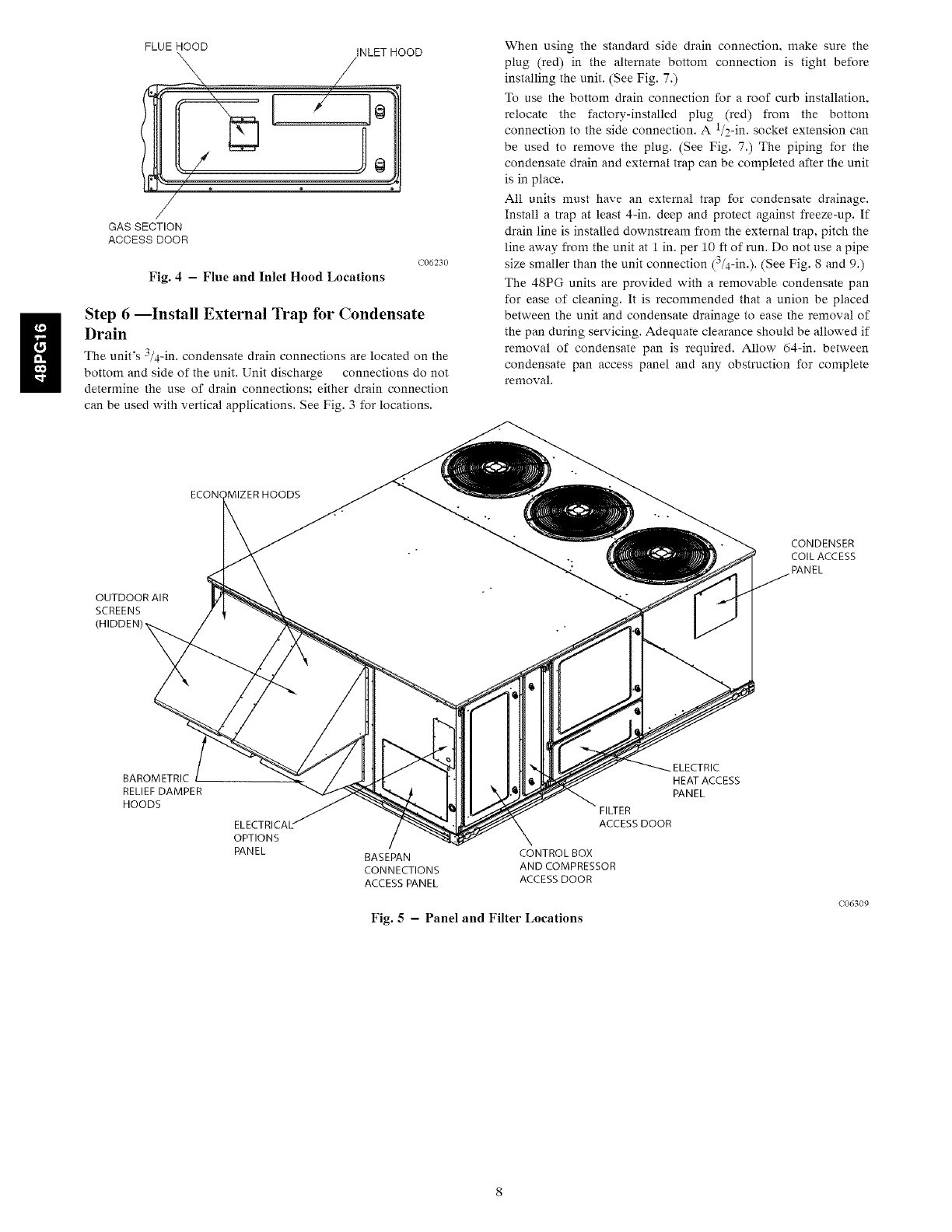
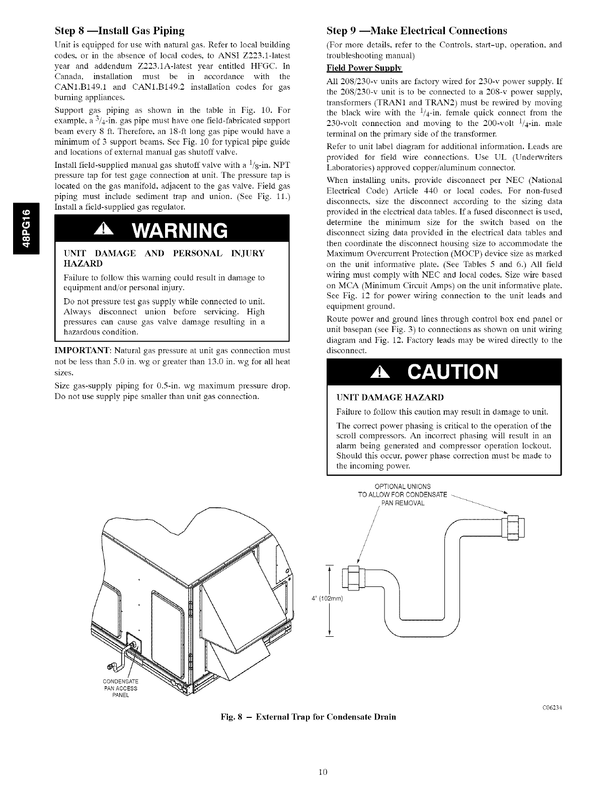
Step 6 --Install External Trap for Condensate
Drain
The unit's 3/4-in. condensate drain connections are located on the
bottom and side of the unit. Unit discharge connections do not
determine the use of drain connections: either drain connection
can be used with vertical applications. See Fig. 3 for locations.
When using the standard side drain connection, make sure the
plug (red) in the alternate bottom connection is tight before
installing the unit. (See Fig. 7.)
To use the bottom drain connection for a roof curb installation.
relocate the factory-installed plug (red) from the bottom
connection to the side connection. A 1/2-in. socket extension can
be used to remove the plug. (See Fig. 7.) The piping for the
condensate drain and external trap can be completed after the unit
is in place.
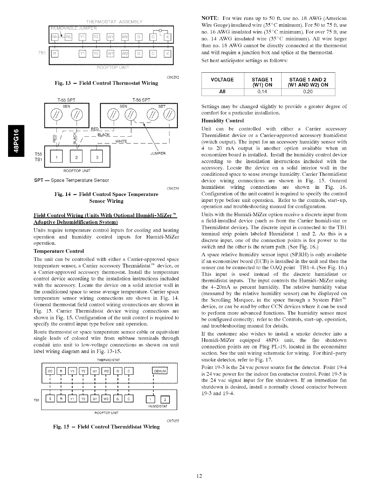
All units must have an external trap for condensate drainage.
Install a trap at least 4-in. deep and protect against freeze-up. If
drain line is installed downstream from the external trap, pitch the
line away from the unit at 1 in. per 10 ft of run. Do not use a pipe
size smaller than the unit connection (3/4-in.). (See Fig. 8 and 9.)
The 48PG units are provided with a removable condensate pan
for ease of cleaning. It is recommended that a union be placed
between the unit and condensate drainage to ease the removal of
the pan during servicing. Adequate clearance should be allowed if
removal of condensate pan is required. Allow 64-in. between
condensate pan access panel and any obstruction for complete
removal.
ECON( ,MIZER HOODS
OUTDOOR AIR
SCREENS
CONDENSER
COIL ACCESS
PANEL
BAROMETRIC
RELIEF DAMPER
HOODS
ELECTRICAL"
OPTIONS
PANEL
ELECTRIC
HEAT ACCESS
PANEL
FILTER
ACCESS DOOR
BASEPAN CONTROL BOX
CONNECTIONS AND COMPRESSOR
ACCESS PANEL ACCESS DOOR
Fig. 5 - Panel and Filter Locations
C06309
MOTOR
MAIN GAS
HEAT COMBUSTION MAIN
EXCHANGER FAN HOUSING BURNER
SECTION SECTION
Fig. 6- Typical Gas Heating Section
C06232
SIDEDRAIN
PLUG
222................
BOTTOMDRAIN
PLUG
C06233
Fig. 7 -Condensate Drain Pan
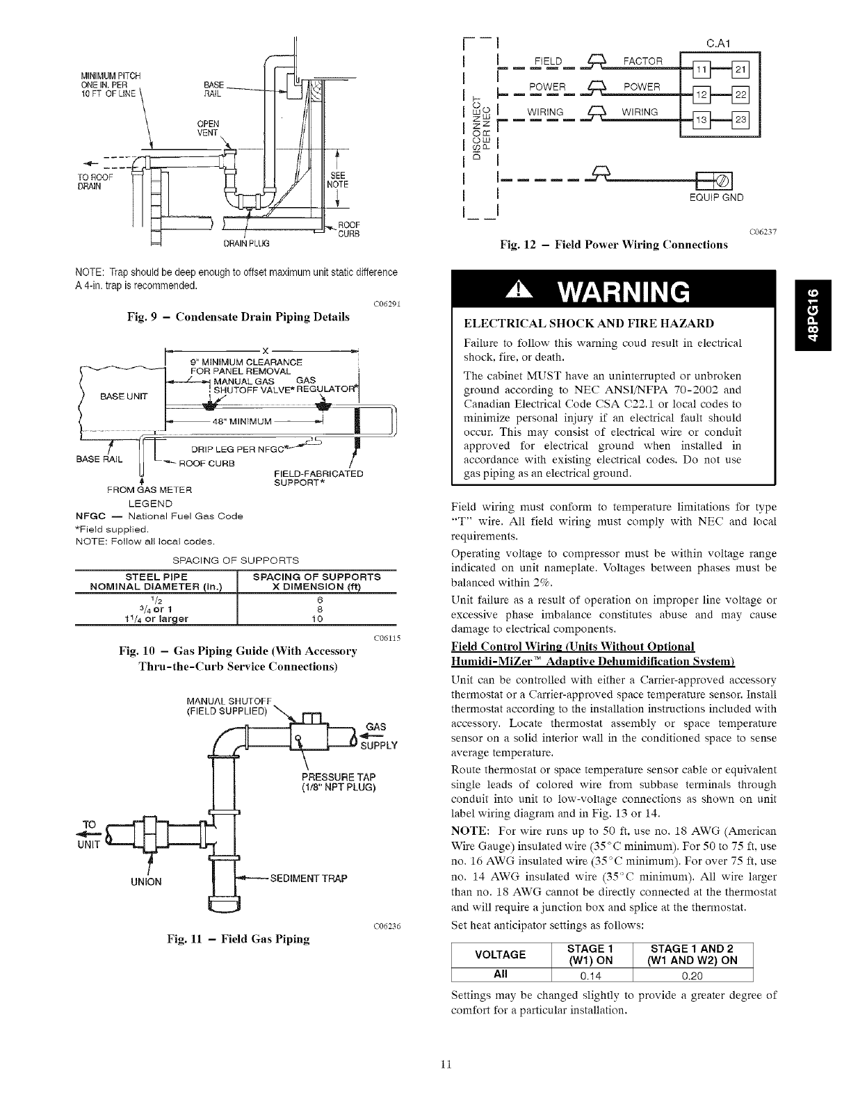
Step 7 --Orifice Change
This unit is factory assembled for heating operation using natural
gas at an elevation from sea level to 2000 ft. This unit uses orifice
type LH32RFnnn, where "nnn" indicates the orifice size based on
drill size diameter in thousands of an inch.
High Elevation (Above 2000 ft)
Use accessory high altitude kit when installing this unit at an
elevation of 2000 to 7000 ft. For elevations above 7000 ft, refer
to Table 2 to identify the correct orifice size for the elevation. See
Table 3 for the number of orifices required for each unit size.
Purchase these orifices from your local Carrier dealer. Follow
instructions in accessory Installation Instructions to install the
correct orifices.
Table 2--Altitude Compensation*
ELEVATION (ft) NATURAL GAS ORIFICE1"
0-1,999 30
2,000 30
3,000 31
4,000 31
5,000 31
6,000 31
7,000 32
8,000 32
9,000 32
10,000 35
11,000 36
12,000 37
13,000 38
14,000 39
*As the height above sea level increases, there is less oxygen per cubic
foot of air. Therefore, heat input rate should be reduced at higher alti-
tudes. Includes a 4% input reduction per each 1000 ft.
1-Orifices available through your Carrier dealer.
Table 3--Orifice Quantity
ORIFICE
UNIT QUANTITY
Low Heat (48PGD/L) 5
Medium Heat (48PGE/M) 7
High Heat (48PGF/N) 9
Conversion to Propane Gas
Use accesso_ propane gas conversion kit when converting this
unit for use with propane fuel usage for elevations up to 7000 ft.
For elevations above 7000 ft, refer to Table 4 to identify the
correct orifice size for the elevation. See Table 3 for the number
of orifices required for each unit size. Purchase these orifices from
your local Carrier dealer. Follow instructions in accesso_
Installation Instructions to install the correct orifices.
Table 4--Propane Gas Conversion*
PROPANE GAS
ELEVATION (ft) ORIFICE1"
0-1,999 38
2,000 40
3,000 40
4,000 41
5,000 41
6,000 42
7,000 42
8,000 43
9,000 43
10,000 44
11,000 44
12,000 45
13,000 46
14,000 47
*As the height above sea level increases, there is less oxygen per cubic
foot of air. Therefore, heat input rate should be reduced at higher atti-
tudes. Includes a 4% input reduction per each 1000 ft.
1-Orifices available through your Carrier dealer.
n
Step 8 --Install Gas Piping
Unit is equipped for use with natural gas. Refer to local building
codes, or in the absence of local codes, to ANSI Z223.1-1atest
year and addendum Z223.1A-latest year entitled HFGC. In
Canada, installation must be in accordance with the
CAN1.B149.1 and CAN1.B149.2 installation codes for gas
burning appliances.
Support gas piping as shown in the table in Fig. 10. For
example, a 3/4-in. gas pipe must have one field-fabricated support
beam every 8 ft. Therefore. an 18-ft long gas pipe would have a
minimum of 3 support beams. See Fig. 10 for typical pipe guide
and locations of external manual gas shutoff valve.
Install field-supplied manual gas shutoff valve with a l/8-in. NPT
pressure tap for test gage connection at unit. The pressure tap is
located on the gas manifold, adjacent to the gas valve. Field gas
piping must include sediment trap and union. (See Fig. 11.)
Install a field-supplied gas regulator.
UNIT DAMAGE AND PERSONAL INJURY
HAZARD
Failure to follow this warning could result in damage to
equipment and/or personal injury.
Do not pressure test gas supply while connected to unit.
Always disconnect union before servicing. High
pressures can cause gas valve damage resulting in a
hazardous condition.
IMPORTANT: Natural gas pressure at unit gas connection must
not be less than 5.0 in. wg or greater than 13.0 in. wg for all heat
sizes.
Size gas-supply piping for 0.5-in. wg maximum pressure drop.
Do not use supply pipe smaller than unit gas connection.
Step 9 --Make Electrical Connections
(For more details, refer to the Controls, start-up, operation, and
troubleshooting manual)
Field Power Supply
All 208/230-v units are factory wired for 230-v power supply. If
the 208/230-v unit is to be connected to a 208-v power supply,
transformers (TRAN1 and TRAN2) must be rewired by moving
the black wire with the l/4-in, female quick connect from the
230-volt connection and moving to the 200-volt l/4-in, male
terminal on the primary side of the transformer.
Refer to unit label diagram for additional information. Leads are
provided for field wire connections. Use UL (Underwriters
Laboratories) approved copper/aluminum connector.
When installing units, provide disconnect per NEC (National
Electrical Code) Article 440 or local codes. For non-fused
disconnects, size the disconnect according to the sizing data
provided in the electrical data tables. If a fused disconnect is used,
determine the minimum size for the switch based on the
disconnect sizing data provided in the electrical data tables and
then coordinate the disconnect housing size to accommodate the
Maximum Overcurrent Protection (MOCP) device size as marked
on the unit informative plate. (See Tables 5 and 6.) All field
wiring must comply with NEC and local codes. Size wire based
on MCA (Minimum Circuit Amps) on the unit informative plate.
See Fig. 12 for power wiring connection to the unit leads and
equipment ground.
Route power and ground lines through control box end panel or
unit basepan (see Fig. 3) to connections as shown on unit wiring
diagram and Fig. 12. Factory leads may be wired directly to the
disconnect.
UNIT DAMAGE HAZARD
Failure to follow this caution may result in damage to unit.
The correct power phasing is critical to the operation of the
scroll compressors. An incorrect phasing will result in an
alarm being generated and compressor operation lockout.
Should this occur, power phase correction must be made to
the incoming power.
CONDENSATE
PAN ACCESS
PANEL
OPTIONALUNIONS
TOALLOWFORCONDENSATE_
PANREMOVAL _
Fig. 8 -External Trap for Condensate Drain
C06234
10
MINIMUMPITCH _-'_t. --
>/
I I _ DRAINPLUG
I
SEE
NOTE
_..ROOF
CURB
NOTE: Trap should be deep enough to offset maximum unit static difference
A 4-in. trap is recommended.
C06291
Fig. 9 - Condensate Drain Piping Details
F X *,--
9" MINIMUM CLEARANCE
_ SHuToPANELREMOVAL {
MANUAL GAS GAS .d
FF VALVE* REGULATOR_ I
R__ DRIP LEG PER NFGC_
BASE ROOF CURB
FIELD-FABRICATED
SUPPORT*
FROM GAS METER
LEGEND
NFGC -- National Fuel Gas Code
*Field supplied.
NOTE: Follow all local codes.
SPACING OF SUPPORTS
STIEEL P,PE ]{ SPACING OF SUPPOBTS
NOMINAL DIAMETER (in.) X DIMENSION (ft)
1/2 _ 6
3/4 Or 1 8
11/4 Or larger 10
C06115
Fig. 10 - Gas Piping Guide (With Accessory
Thru-the-Curb Service Connections)
MANUALSHUTOFF
(FIELDSUPPLIED) "_ r'F1
_'_ SUPPLY
PRESSURETAP
(1/8" NPT PLUG)
LINIT UNO__N _- '_----- SEDIMENTTRAP
C06236
Fig. 11 - Field Gas Piping
zLU
Z Z
OCt
©LU
£3
Jm[
I
I
I
r
I
I
I
I
FIELD _ FACTOR
POWER
WIRING ff:_ WIR!_G
C.A1
EQUIP GND
C06237
Fig. 12 - Field Power Wiring Connections
ELECTRICAL SHOCK AND FIRE HAZARD
Failure to follow this warning coud result in electrical
shock, fire. or death.
The cabinet MUST have an uninterrupted or unbroken
ground according to NEC ANSI/NFPA 70-2002 and
Canadian Electrical (:ode CSA C22.1 or local codes to
minimize personal injury if an electrical fault should
occur. This may consist of electrical wire or conduit
approved for electrical ground when installed in
accordance with existing electrical codes. Do not use
gas piping as an electrical ground.
Field wiring must conform to temperature limitations for type
"T" wire. All field wiring must comply with NEC and local
requirements.
Operating voltage to compressor nmst be within voltage range
indicated on unit nameplate. Voltages between phases must be
balanced within 2%.
Unit failure as a result of operation on improper line voltage or
excessive phase imbalance constitutes abuse and may cause
damage to electrical components.
Field Control Wiring (Units Without Optional
Humidi-MiZer TM Adaptive Dehumidification System)
Unit can be controlled with either a Carrier-approved accessory
thermostat or a Carrier-approved space temperature sensor. Install
thermostat according to the installation instructions included with
accessory. Locate thermostat assembly or space temperature
sensor on a solid interior wall in the conditioned space to sense
average temperature.
Route thermostat or space temperature sensor cable or equivalent
single leads of colored wire from subbase terminals through
conduit into unit to low-voltage connections as shown on unit
label wiring diagram and in Fig. 13 or 14.
NOTE: For wire runs up to 50 ft. use no. 18 AWG (American
Wire Gauge) insulated wire (35 °C minimum). For 50 to 75 ft, use
no. 16 AWG insulated wire (35°C minimum). For over 75 ft, use
no. 14 AWG insulated wire (35°C minimum). All wire larger
than no. 18 AWG cannot be directly connected at the thermostat
and will require a junction box and splice at the thermostat.
Set heat anticipator settings as follows:
STAGE 1 STAGE 1 AND 2
VOLTAGE (Wl) ON (Wl AND W2) ON
All 0.14 0.20
Settings may be changed slightly to provide a greater degree of
comfort for a particular installation.
n
11
::: ): :,
::C(' T( :: t,,t
C06292
Fig. 13 - Field Control Thermostat Wiring
T-56 SPT
SEN SET
JUMPER
SPT -- Space Temperature Sensor
Fig. 14 - Field Control Space Temperature
Sensor Wiring
C06239
Field Control Wiring (Units With Optional Humidi-MiZer TM
Adaptive Dehumidification System)
Units require temperature control inputs for cooling and heating
operation and humidity control inputs for Humidi-MiZer
operation.
Temperature Control
The unit can be controlled with either aCarrier-approved space
temperature sensor, a Carrier accessory Thermidistat TM device, or
a Carrier-approved accessory thermostat. Install the temperature
control device according to the installation instructions included
with the accessory. Locate the device on a solid interior wall in
the conditioned space to sense average temperature. Carrier space
temperature sensor wiring connections are shown in Fig. 14.
General thermostat field control wiring connections are shown in
Fig. 13. Carrier Thermidistat device wiring connections are
shown in Fig. 15. Configuration of the unit control is required to
specify the control input type before unit operation.
Route thermostat or space temperature sensor cable or equivalent
single leads of colored wire from subbase terminals through
conduit into unit to low-voltage connections as shown on unit
label wiring diagram and in Fig. 13-15.
THERMIDISTAT
TBI
DUE c DDD
I I I I I I I I I
I I I I I I I I I
I I I I I I I I I
RUMIDISTAT
ROOFTOP UNIT
C07055
Fig. 15 - Field Control Thermidistat Wiring
NOTE: For wire runs up to 50 ft, use no. 18 AWG (American
Wire Gauge) insulated wire (35 °C minimum). For 50 to 75 ft, use
no. 16 AWG insulated wire (35°C minimum). For over 75 ft, use
no. 14 AWG insulated wire (35"_C minimum). All wire larger
than no. 18 AWG cannot be directly connected at the thermostat
and will require a junction box and splice at the thermostat
Set heat anticipator settings as follows:
VOLTAGE STAGE 1 STAGE 1 AND 2
(Wl) ON (Wl AND W2) ON
All 0.14 0.20
Settings may be changed slightly to provide a greater degree of
comfort for a particular installation.
Humidity Control
Unit can be controlled with either a Carrier accessory
Thermidistat device or a Carrier-approved accessory humidistat
(switch output). The input for an accessory humidity sensor with
4 to 20 mA output is another option available when an
economizer board is installed. Install the humidity control device
according to the installation instructions included with the
accessory. Locate the device on a solid interior wall in the
conditioned space to sense average humidity. Carrier Thermidistat
device wiring connections are shown in Fig. 15. General
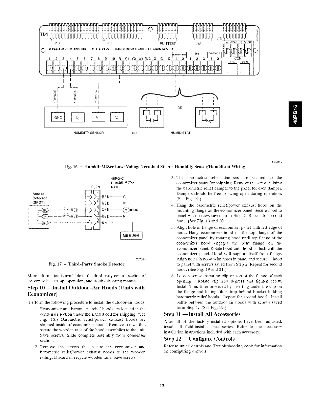
humidistat wiring connections are shown in Fig. 16.
Configuration of the unit control is required to specify the control
input type before unit operation. Refer to the controls, start-up,
operation and troubleshooting manual for configuration.
Units with the Humidi-MiZer option receive a discrete input from
a field-installed device (such as from the Carrier humidi-stat or
Thermidistat device). The discrete input is connected to the TB1
terminal strip points labeled Humidistat 1 and 2. As this is a
discrete input, one of the connection points is for power to the
switch and the other is the return path. (See Fig. 16.)
A space relative humidity sensor input (SP.RH) is only available
if an economizer board (ECB) is installed in the unit and then the
sensor can be connected to the OAQ point TB1-4. (See Fig. 16.)
This input is used instead of the discrete humidistat or
thermidistat inputs. The input controls the Humidi-MiZer using
the 4-20mA as percent humidity. The relative humidity value
(measured by the relative humidity sensor) can be displayed on
the Scrolling Marquee, in the space through a System PiloU"
device, or can be read by other CCN devices where it can be used
to perform more advanced functions. The humidity sensor must
be configured correctly; refer to the Controls, start-up, operation,
and troubleshooting manual for details.
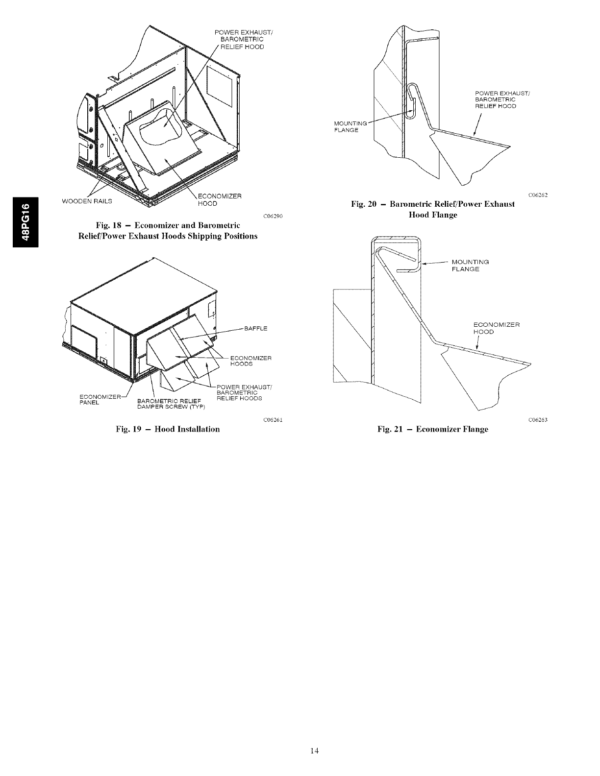
If the customer also wishes to install a smoke detector into a
Humidi-MiZer equipped 48PG unit. the fire shutdown
connection points are on Plug PL-19, located in the economizer
section. See the unit wiring schematic for wiring. For third-party
smoke detector, refer to Fig. 17.
Point 19-3 is the 24 vac power source for the detector. Point 19-4
is 24 vac power for the indoor fan contactor control. Point 19-5 is
the 24 vac signal input for fire shutdown. If an immediate fan
shutdown is desired, install a normally closed contactor between
19-3 and 19-4.
12
I I
I I
J I
OR
HUMIDITY SENSOR OR HUMIDISTAT
Fig. 16 - Humidi-MiZer Low-Voltage Terminal Strip -Humidity Sensor/Humidistat Wiring
C07045
Pk19
smoke _[-:
Detector' @ N
(SPOT) ; _ )-
48PG_
Humldi;-MiZer
RTU
Fig. 17 - Third-Party Smoke Detector
C07046
More information is available in the third party control section of
the controls, start-up, operation, and troubleshooting manual.
Step 10 --Install Outdoor-Air Hoods (Units with
Economizer)
Perform the following procedure to install the outdoor-air hoods:
1. Economizer and barometric relief hoods are located in the
condenser section under the slanted cnil fnr shipping. (See
Fig. 18.) Barometric relief/power exhaust hoods are
shipped inside of economizer hoods. Remove screws that
secure the wooden rails of the hood assemblies to the unit.
Save screws. Slide complete assembly from condenser
section.
2. Remove the screws that secure the economizer and
barometric relief/power exhaust hoods to the wooden
railing. Discard or recycle wooden rails. Save screws.
3. The barometric relief dampers are secured to the
economizer panel for shipping. Remove the screw holding
the barometric relief damper to the panel for each damper.
Dampers should be free to swing open during operation.
(See Fig. 19.)
4. Hang the barometric relief/power exhaust hood on the
mounting flange on the economizer panel. Secure hood to
panel with screws saved from Step 2. Repeat for second
hood. (See Fig. 19 and 20.)
5. Align hole in flange of economizer panel with left edge of
hood. Hang economizer hood on the top flange of the
economizer panel by rotating hood until top flange of the
economizer hood engages the bent flange on the
economizer panel. Rotate hood until hood is flush with the
economizer panel. Hood will support itself from flange.
Align holes in hood with holes in panel and secure hood
to panel with screws saved from Step 2. Repeat for second
hood. (See Fig. 19 and 21.)
6. Loosen screws securing clip on top of the flange of each
opening. Rotate clip 180 degress and tighten screw.
Install l-in. filter provided by inserting under the clip on
the flange and letting filter drop behind bracket holding
barometric relief hoods. Repeat for second hood. Install
baffle between the outdoor air hoods with screws saved
form Step 1. (See Fig. 19.)
Step 11 --Install All Accessories
After all of the factory-installed options have been adjusted,
install all field-installed accessories. Refer to the accessory
installation instructions included with each accessory.
Step 12 --Configure Controls
Refer to unit Controls and Troubleshooting book for information
on configuring controls.
13
POWER EXHAUST/
BAROMETRIC
MOUNTING /
FLANGE
POWER EXHAUST/
BAROMETRIC
RELIEF HOOD
/
nECONOMIZER
WOODEN RAILS HOOD
Fig. 18 - Economizer and Barometric
Relief/Power Exhaust Hoods Shipping Positions
C06290
BAFFLE
ECONOMIZER
HOODS
XHAUST/
ECONOMIZER _ i BAROMETRIC
PANEL BAROMETRIC RELIEF RELIEF HOODS
DAMPER SCREW (TYP)
C06261
Fig. 19 -Hood Installation
Fig. 20 - Barometric Relief/Power Exhaust
Hood Flange
MOUNTING
FLANGE
ECONOMIZER
HOOD
J
Fig. 21 - Economizer Flange
(;06262
(;06263
14
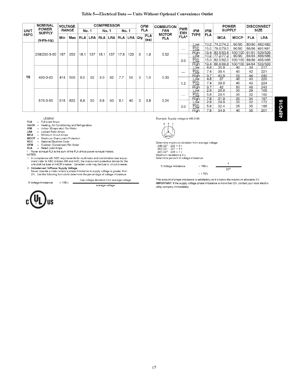
Table5--Electrical Data -- Units Without Optional Convenience Outlet
NOMINAL
UNIT POWER
48PG SUPPLY
(V-Ph-Hz)
208/230-3-60
16 460-3-60
575-3-60
VOLTAGE COMPRESSOR OFM COMBUTION
RANGE No. 1 No. 1 No. 1 FLA FAN
FLA MOTOR
Min Max RLA LRA RLA LRA RLA LRA Qty (ea) FLA
187 253 18.1 137 18.1 137 17.6 123 3 1.9 0.52
414 506 9.0 62 9.0 62 7.7 50 3 1.0 0.30
518 633 6.8 50 6.8 50 6.1 40 3 0.8 0.24
PWR
EXH
FLA*
3.0
1.2
3.0
POWER
IFM IFM SUPPLY
TYPE FLA MCA MOCP
Low 10.2 74.2/74.2 90/90
_'_ 15.0 79.0/79.0 90/90
Hioh 19.4 83.8/63.8 100/100
Low 10.2 77.2/77.2 90/90
_'_ 15.0 82.0/82.0 100/100
High 19.4 86.8/66.8 100/100
I ow 4 8 35 8 40
_ni$ 7.4 38.4 45
Hinh 9 7 40 8 50
Lo_w 4.8 37 45
_7.4 39.6 45
High 9,7 42 50
Low 2.8 26.6 30
_V_dA] 5.6 29.4 35
High 7.8 31.9 35
I ow P 8 P9 6 35
_ 5.6 32.4 35
Hiah 7,6 34,9 40
DISCONNECT
SIZE
FLA LRA
80/80 482/482
86/86 491/491
91/91 529/529
84/84 486/486
89/89 495/495
94/94 533/533
39 917
42 221
44 940
40 220
43 224
46 243
29 168
32 182
34 197
39 179
35 186
38 201
LEGEND
FLA - Full Load Amps
HACR - Reating, Air Condltioning and Refrigeration
IFM -indoor (Evaporator) Fan Motor
LRA - Looked Rotor Amps
MCA - MinimumCircuitAmps
MOCP- MaximumOvercurrentProtection
NEC -National E]eotdcal Code
OFM - Outdoor (Condenser) Fan Motor
RLA -Rated Load Amps
* Power exhaust FLA is the sum of the FLA of two power exhaust motors
NOTES:
1 In compliance with NED requirements for multimotor and combination load equip-
ment (refer to NEC Articles 430 and 440), the overcurrent protective device for the
unit shall be fuse or HACR breaker Canadian units may be fuse or circuit breaker
2 Unbalanced 3-Phase Supply Voltage
Never operate a motor where a phase imbalance in supply voltage is greater than
2% Use the following formula to determine the percentage of voltage imbalance
max voltage deviation from average voltage
% Voltage Imbalance = 1 go x
average voltage
Example: Supply vo{tage is 460-3-60
,_ B c
Determine maximum deviation from average voltage
(AB) 227 223 3 v
(BC) 231 227 4v
(AO) 227 226 1 v
Maximum deviation is 4v
Determine percent of voltage imbalance
%Voltage imbalance = 1 go x
= 1 76%
4
227
This amount of phase imbalance is satisfactory as it is below the maximum allowable 2%
IMPORTANT: If the supply voltage phase imbalance is more than 2%, contact your local electric
utility company immediately
!!
15
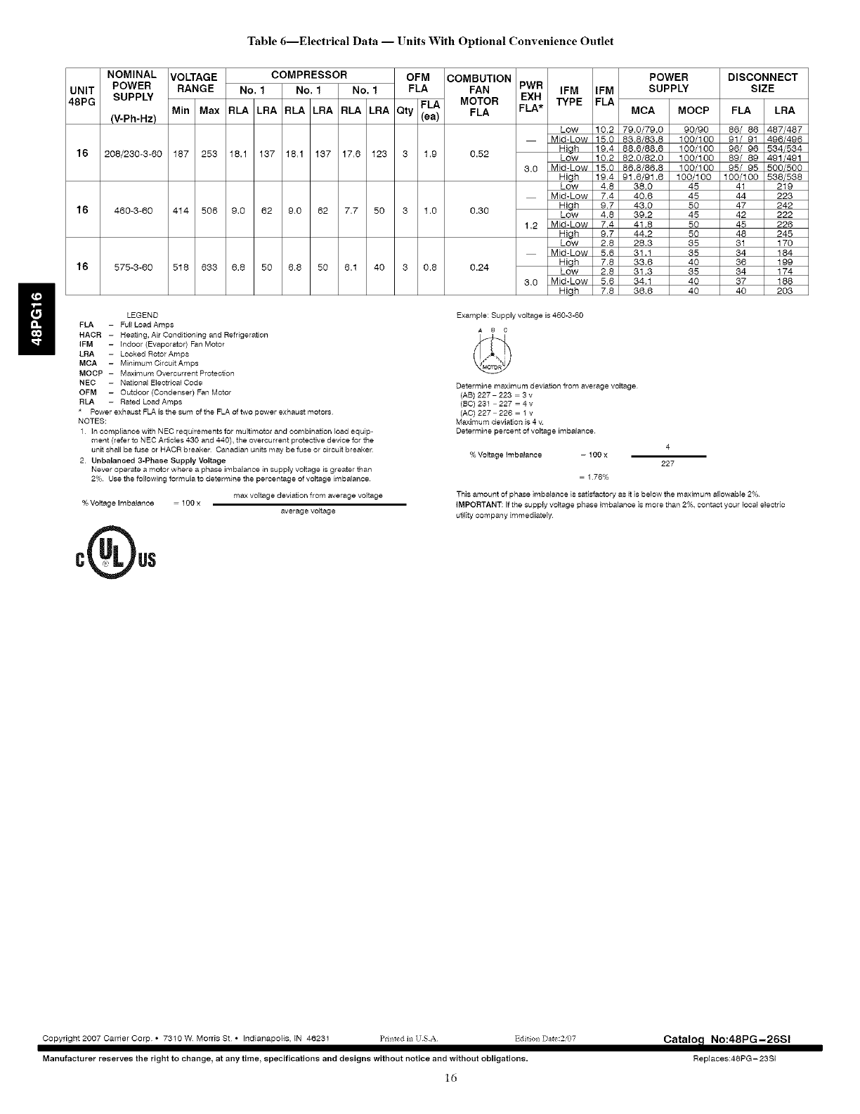
Table 6---Electrical Data -- Units With Optional Convenience Outlet
UNIT
48PG
16
16
16
NOMINAL
POWER
SUPPLY
(V-Ph-Hz)
208/230-3-80
460-3-80 414 506 9,0 82
575-8-80 518 883 8,8 50
VOLTAGE COMPRESSOR OFM COMBUTION
RANGE No. 1No. 1No. 1FLA FAN PWR
FLA MOTOR EXH
Min Max RLA LRA RLA LRA RLA LRA Qty (ea) FLA FLA*
187 253 18.1 137 18.1 137 17.6 123 3 1.9 0.52
9,0 82 7.7 50 31.0 0.30
8.8 50 8.1 40 3 0.8 0.24
LEGEND
FLA - Full Load Amps
HACR - Heating, Air Conditioning and Refrigeration
IFM -indoor (Evaporator) Far) Motor
LRA - Locked Rotor Amps
MCA - MinimumCircuitAmps
MOCP- MaximumOvercurrentProtaction
NEC - National Eleotdcal Code
OFM - Outdoor (Condenser) Fan Motor
RLA - Rated Load Amps
* Power exhaust FLA. is the sum of the FLA of two power exhaust motors
NOTES:
1in compliance with NEC requirements for multimotor and combination load equip-
ment (refer to NEC Articles 430 and 440), the overcurrent protective device for the
unit shall be fuse or HACR breaker Canadian units may be fuse or circuit breaker
2 Unbalanced 3-Phase Supply Voltage
Never operate a motor where a phase imbalance in supply voltage is greater than
2% Use the following formula to determine the percentage of voltage imbalance
max voltage deviation from average voltage
% Voltage Imbalance 1 go x
average voltage
IFM IFM
TYPE FLA
POWER
SUPPLY
MCA MOCP
Low 10,2 79.0/79.0 90/90
Mid-Low 15,0 83.8/83.8 100/100
High 19,4 88.8/88.8 100/100
Low 10,2 82.0/82.0 100/100
3,0 Mid-Low 15,0 86.8/86.8 100/100
High 19,4 91.8/91.8 100/100
DISCONNECT
SIZE
FLA LRA
86/ 86 487/487
91/ 91 498/496
96/ 98 534/534
89/ 89 491/491
95/ 95 500/500
!00/!00 538/538
Low 4,8 38,0 45
Mid-Low 7,4 40,6 45
High 9,7 43,0 50
Low 4,8 39,2 45
1,2 Mid-Low 7,4 41,8 50
High 9,7 44,2 50
Low 2,8 28,3 35
Mid-Low 5,6 31,1 35
High 7,8 33,6 40
Low 2.8 31,3 35
3,0 Mid-Low 5,6 34,1 40
Hiqh 7,8 36,6 40
41 219
44 223
47 242
42 222
45 228
48 245
31 170
34 184
38 199
34 174
37 188
40 203
Example: Supply vo{tage is 460-3-60
,_ e c
Determine maximum deviation from average voltage
(AB) 227 223 3 v
(BC) 231 227 4v
(AO) 227 226 1 v
Maximum deviation is 4v
Determine percent of voltage imbalance
% Voltage imbalance 1 go x
1 76%
4
227
This amount of phase imbalance is satisfactory as it is below the maximum allowable 2%
IMPORTANT: If the supply voltage phase imbalance is more than 2%, contact your local electric
utility company immediately
Copyright 2007 Cartier Corp ° 7310 W Morris St • Indianapolis, IN 46231 ]_dnted ta USA
Manufacturer reserves the right to change_ at any tirne_ specifications and designs without notice and without obligations.
ld
Catalol_ No:48PG-26SI
Replaces:48PG - 23SI
