CARRIER Package Units(both Units Combined) Manual L0709352
User Manual: CARRIER CARRIER Package Units(both units combined) Manual CARRIER Package Units(both units combined) Owner's Manual, CARRIER Package Units(both units combined) installation guides
Open the PDF directly: View PDF ![]() .
.
Page Count: 7
Wall Thermostat Interface Retrofit Kit Accessory For
Packaged Terminal Air Conditioner
or Heat Pump
Cancels: IlK 84-07-7
Installation Instructions
IlK 84-07-13
9/1/04
SAFETY CONSIDERATIONS
Only trained, qualified personnel and service mechanics
should install electrical accessories on packaged terminal air
conditioners or heat pumps.
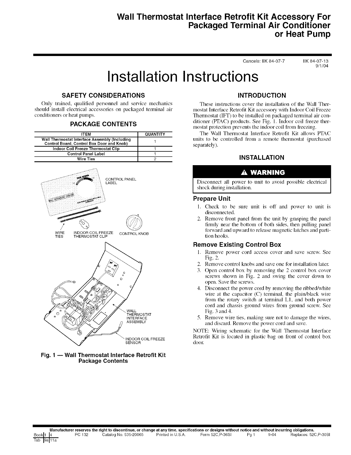
PACKAGE CONTENTS
ITEM QUANTITY
Wall Thermostat Interface Assembly (Including 1
Control Board, Control Box Door and Knob)
Indoor Coil Freeze Thermostat Clip 1
Control Panel Label 1
Wire Ties 2
INTRODUCTION
These instructions cover the installation of the Wall Ther-
mostat Interface Retrofit Kit accessory with Indoor Coil Freeze
Therlnostat (IFT) to be installed on packaged temtinal air con-
ditioner (PTAC) products. See Fig. 1. Indoor coil fieeze ther-
mostat protection prevents the indoor coil fiom freezing.
The Wall Thermostat Interface Retrofit Kit allows PTAC
units to be controlled from a remote thermostat (purchased
sep_u'ately).
INSTALLATION
CONTROLPANEL
LABEL
WIRE INDOOR COIL FREEZE CONTROL KNOB
TIES THERMOSTAT CLIP
WALL
THERMOSTAT
INTERFACE
ASSEMBLY
_INDOOR COILFREEZE
SENSOR
Fig. 1 -- Wall Thermostat Interface Retrofit Kit
Package Contents
Disconnect all power to unit to avoid possible electrical
shock during inst_dlation.
Prepare Unit
I. Check to be sure unit is off and power to unit is
disconnected.
2. Remove front panel frt)m the unit by grasping the panel
firmly near the bottom of both sides, then pulling panel
forward and upward to release magnetic latches and p_u'ti-
tion hooks.
Remove Existing Control Box
1. Relnove power cord access cover and save screw. See
Fig. 2.
2. Remove control knobs and save one for inst_dlation later
3. Open control box by removing the 2 control box cover
screws shown in Fig. 2 and swing the cover down to
open. Save the screws.
4. Disconnect the power cord by removing the ribbed/white
wire at the capacitor (C) terminal, the plain/black wire
from the rotguy switch at terminal LI, and both power
cord and chassis ground wires from ground screw. See
Fig. 3 and 4.
5. Remove wire ties, making sum not to damage the wires,
and discard. Remove the power cord and save.
NOTE: Wiring schematic for the Wall Thermostat Interface
Retrofit Kit is located in plastic bag on front of control box
door
Manufacturer reserves the right to discontinue, or change at any time, specifications or designs without notice and without incurring obligations.
PC 132 Catalog No. 535-20065 Printed in U.S.A. Form 52C,P-36SI Pg 1 9-04 Replaces: 52C,P-3081
POWER
CORD
ACCESS
COVER
CORD
CONTROL
• BOX COVER
SCREWS
OUTDOOR
THERMOSTAT
(OFT)
MOUNTING
SCREWS
Fig. 2 -- Control Box Component Location
_/ WIRE TIE
OUTDOOR COIL
FREEZE THERMOSTAT
(OFT)
RIBBED/WHITE WIRE (L2)
TO CAPACITOR (C)
WIRE TIE
PLAIN/BLACK WIRE (L1)
GROUND SCREW TO ROTARY SWITCH
(GND) RED
YELLOW_ PINK
BLACK _ BLACK
INDOOR _ = ROTARY SWITCH
THERMOSTAT _
Fig. 3 iTypical Control Wiring -- Standard Units
(Heat Pump Unit Shown)
Select Unit -- Refer to the installation instructions for the
unit being retrofit. For Cooling with Electric Heat units see
below. For Heat Pump units see page 3. For Cooling Only units
see page 5.
COOLING WITH ELECTRIC HEAT UNITS
1. Remove the following wires from the rotary switch:
a. Yellow wire from COME
b. Red fan motor wire from LO, and the black fan motor
wire from HI.
c. Pink wire from L2.
d. Red wire from LS.
e. Violet heater wire from HT.
2. Remove the control box door and thermostat bulb from
front of coil and discard.
3. Reinstall the previously saved power cord access cover to
the new control box door supplied with kit.
4. Attach the new control box door by sliding it onto the
control box hinge pins. See Fig. 5.
5. Secure power cord, control board and chassis ground
wiles to control box door
6. Attach ribbed/white wire (L2) from power cord to temfi-
nal C on capacitol: See Fig. 4.
7. Reconnect the following wires on control board (see
Fig. 6):
a. Plain/black wire (LI) from power cord to LI (brass
post terminal) on lelay K2.
b. Pink wire to L2 on relay K2AI.
c. Violet heater wire to Heat2 on lelay K2AI.
NOTE: The male piggy back terminal is not used.
This termimd may either be removed or pinched back
to fit the connector onto Heat2 relay terminal.
d. Red heater wire to Heatl on relay K2.
e. Yellow compressor wire to COME on relay KI.
8. Attach the Red fan motor wire to termimd 1 on fan speed
selector switch (FSS) and the Black fan motor wile to ter-
minal 3 on FSS. See Fig. 6.
9. Dress wiles using wire ties provided. See Fig. 7.
10. Close the control box door and secure by re-attaching
screws saved earliel:
11. Attach control knob that was removed earliel: to fan
speed selector switch.
12. Install Indoor Coil Freeze Thermostat (IFT) into coil.
a. Use a pen to m_ke an opening in the fins to install
freeze sensor (Fig. 8).
• For 7000 Btuh and 9000 Btuh units, make an open-
ing 4-in. fiom the right side of the coil between the
third and fourth row from the top.
• For 12,000 Btuh and 15,000 Btuh units, make an
opening 4-in. from the right side of the coil
between the second and third row fiom the top.
b. Route Indoor Coil Freeze Sensor:
• Remove disch;uge deck. See Fig. 8.
• Route fieeze sensor fiom PC board through plastic
bushing in side panel with electric heater wiles. See
Fig. 7.
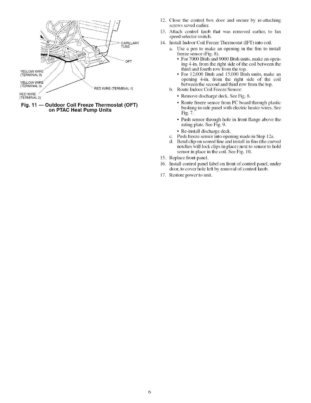
• Push sensor through hole in fi_)nt flange above the
_uting plate. See Fig. 9.
• Re-install discharge deck.
c. Push freeze sensor into opening made in Step 12a.
d. Bend clip on scored line and install in fins (the curved
notches will lock clips in place) next to sensor to hold
sensor in place in the coil. See Fig. 10.
13. Replace front panel.
14. Install control panel label on front of control panel, under
door. to cover hole left by removal of control knob.
15. Restore power to unit.
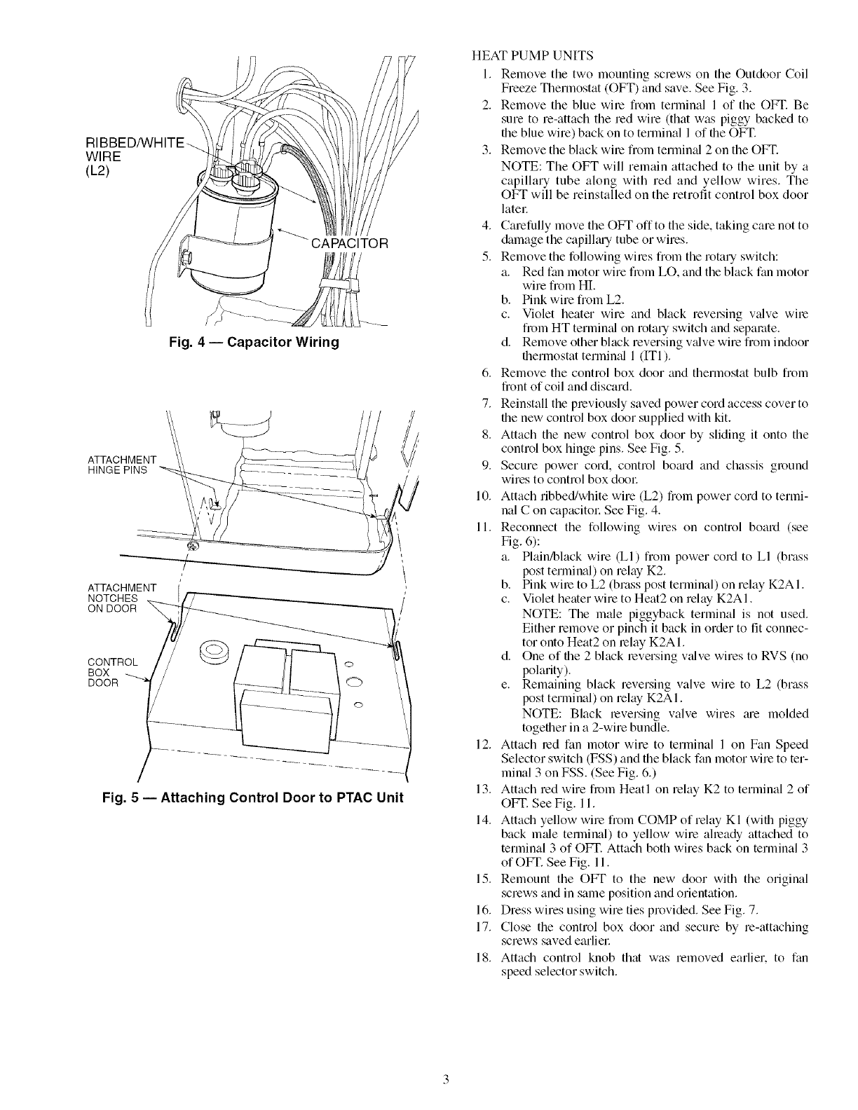
WIRE
(L2)
Fig. 4 -- Capacitor Wiring
ATTACHMENT
HINGE PINS
ATTACHMENT (
NOTCHES _ [/'7--"-"_
ON DOOR %_ _,
BOX --__J / / /l \ _-. /
Fig. 5 -- Attaching Control Door to PTAC Unit
HEAT PUMP UNITS
1. Remove the two mounting screws on the Outdoor Coil
Freeze Thermostat (OFT) and save. See Fig. 3.
2. Remove the blue wile from terminal 1 of the OFT. Be
sure to re-attach the red wire (that was piggy backed to
the blue wire) back on to terminal 1 of file OFT.
3. Remove the black wile from terminal 2 on the OFT.
NOTE: The OFT will remain attached to the unit by a
capillary tube along with red and yellow wires. The
OFT will be reinstalled on the retrofit control box door
latec
4. Carefully move the OFT offto the side, taking care not to
damage the capillmy tube or wires.
5. Remove the following wiles from the rotary switch:
a. Red fan motor wire from LO, and the black fan motor
wire from HI.
b. Pink wire from L2.
c. Violet heater wire and black revel.sing valve wile
from HT terminal on rotary switch and separate.
d. Remove other black reversing v_dvewire from indoor
thermostat termimd 1 (ITI).
6. Remove the control box door and thermostat bulb from
front of coil and discard.
7. Reinstall the previously saved power cord access cover to
file new control box door supplied with kit.
8. Attach the new control box door by sliding it onto the
control box hinge pins. See Fig. 5.
9. Secure power cord, control bomd and chassis ground
wires to control box dool:
10. Attach ribbed/white wire (L2) from power cord to termi-
nal C on capacitol: See Fig. 4.
11. Reconnect the following wires on control board (see
Fig. 6):
a. Plain/black wire (LI) fiom power cord to LI (brass
post terminal) on relay K2.
b. Pink wire to L2 (brass post terminal) on relay K2AI.
c. Violet heater wire to Heat2 on relay K2AI.
NOTE: The male piggyback terminal is not used.
Either remove or pinch it back in order to fit connec-
tor onto Heat2 on relay K2AI.
d. One of the 2 black reversing valve wires to RVS (no
polarity).
e. Remaining black reversing valve wire to L2 (brass
post terminal) on relay K2AI.
NOTE: Black reversing valve wires me molded
together in a 2-wire bundle.
12. Attach md fan motor wire to terminal 1 on Fan Speed
Selector switch (FSS) and the black fan motor wire to ter-
minal 3 on FSS. (See Fig. 6.)
13. Attach md wire from Heatl on relay K2 to terminal 2 of
OFT. See Fig. 11.
14. Attach yellow wire fiom COMP of relay KI (with piggy
back male terlninal) to yellow wire already attached to
terminal 3 of OFT. Attach both wires back on terminal 3
of OFT. See Fig. 11.
15. Remount the OFT to the new door with the original
screws and in same position and orientation.
16. Dress wires using wire ties provided. See Fig. 7.
17. Close the control box door and secure by re-attaching
screws saved earliec
18. Attach control knob that was removed earlier, to fan
speed selector switch.
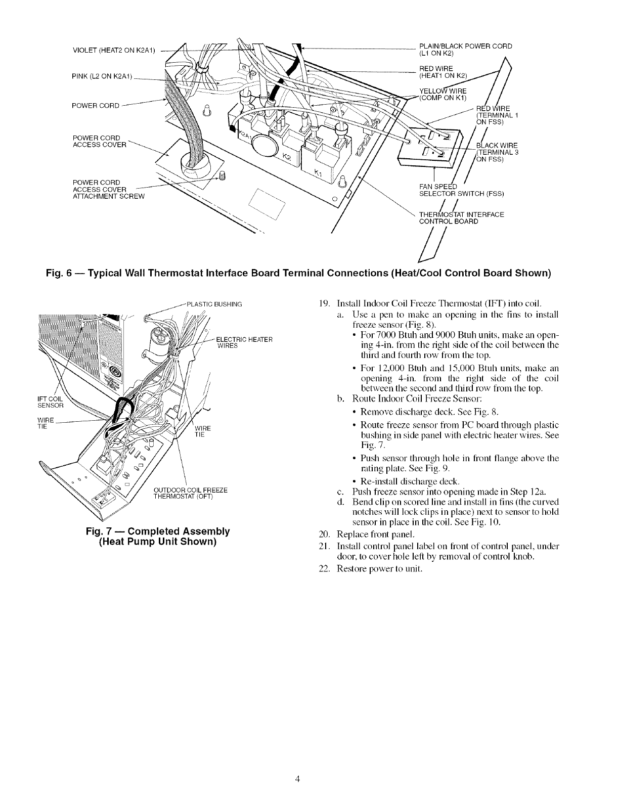
PLAIN/BLACK POWER CORD
VIOLET (HEAT2 ON K2A1) (L1 ON K2)
RED WIRE
PINK (L2 ON K2A1) (H EATI_,_,// /
POWER CORD YELLOW WIRE //
RED WIRE
(TERMINAL 1
ON FSS)
POWER CORD /
ACCESS BLACK WIRE
POWER CORD
ACCESS COVER
ATTACHMENT SCREW
FAN SPEED
SELECTOR SWITCH (FSS)
//
THERMOSTAT INTERFACE
CONTROL BOARD
#
Fig. 6 -- Typical Wall Thermostat Interface Board Terminal Connections (Heat/Cool Control Board Shown)
IFT COIL
SENSOR
WIRE
TIE
BUSHING
/ ELECTRIC HEATER
WIRES
TIE
OUTDOOR COIL FREEZE
THERMOSTAT (OFT)
Fig. 7 -- Completed Assembly
(Heat Pump Unit Shown)
19. Install Indoor Coil Freeze Thermostat (Ibm) into coil.
a. Use a pen to make an opening in the fins to install
freeze sensor (Fig. 8).
• For 7000 Btuh and 9000 Btuh units, make an open-
ing 4-in. from the right side of the coil between the
third and fourth row from the top.
• For 12,000 Btuh and 15,000 Btuh units, make an
opening 4-in. from file right side of file coil
between the second and third row from the top.
b. Route Indoor Coil Freeze Sensor:
• Remove dischtuge deck. See Fig. 8.
• Route freeze sensor from PC board through plastic
bushing in side panel with electric heater wiles. See
Fig. 7.
• Push sensor through hole in fiont flange above the
rating plate. See Fig. 9.
• Re-install discharge deck.
c. Push fieeze sensor into opening made in Step 12a.
d. Bend clip on scored line and install in fins (the curved
notches will lock clips in place) next to sensor to hold
sensor in place in the coil. See Fig. 10.
20. Replace fiont panel.
21. Install control panel label on fiont of control panel, under
door, to cover hole left by removal of control knob.
22. Restore power to unit.
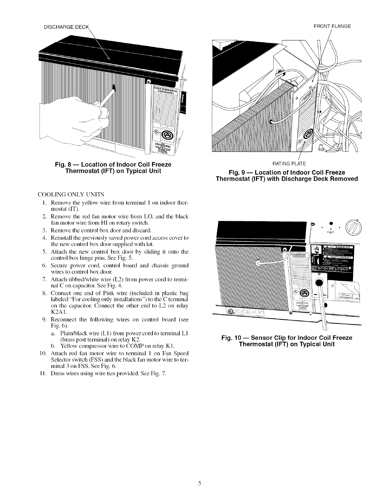
DISCHARGE DECK FRONT FLANGE
Fig. 8 -- Location of Indoor Coil Freeze
Thermostat (IFT) on Typical Unit
COOLING ONLY UNITS
1. Remove the yellow wire fiom terminal 1 on indoor ther-
mostat (IT).
2. Remove the red fan motor wire fiom LO, and the black
fan motor wire from HI on rotary switch.
3. Remove the control box door and discard.
4. Reinstall the previously saved power cord access cover to
the new control box door supplied with kit.
5. Attach the new control box door by sliding it onto the
control box hinge pins. See Fig. 5.
6. Secure power cord, control board and chassis ground
wiles to control box dool:
7. Attach ribbed/white wire (L2) fiom power cord to temfi-
nal C on capacitol: See Fig. 4.
8. Connect one end of Pink wire (included in plastic bag
labeled "For cooling only installations") to the C termimd
on the capacitoc Connect the other end to L2 on lelay
K2A 1.
9. Reconnect the following wires on control board (see
Fig. 6).
a. Plain/black wire (LI) from power cord to termimd LI
(brass post terminal) on relay K2.
b. Yellow compressor wire to COMP on relay KI.
10. Attach red fan motor wire to terminal 1 on Fan Speed
Selector switch (FSS) and the black fan motor wile to ter-
minal 3 on FSS. See Fig. 6.
11. Dress wiles using wire ties provided. See Fig. 7.
RATINGPLATE
Fig. 9 -- Location of Indoor Coil Freeze
Thermostat (IFT) with Discharge Deck Removed
Fig. 10 -- Sensor Clip for Indoor Coil Freeze
Thermostat (IFT) on Typical Unit
TUBE
YELLOW WIRE
(TERMINAL 3)
OFT
YELLOW WIRE _
(TERMINAL 3) \ RED WIRE (TERMINAL 1)
RED WIRE
(TERMINAL 2)
Fig. 11 -- Outdoor Coil Freeze Thermostat (OFT)
on PTAC Heat Pump Units
12. Close file control box door and secure by re-attaching
screws saved eafliel:
13. Attach control knob that was removed earliel: to fan
speed selector switch.
14. Install Indoor Coil Freeze Thermostat (IF_) into coil.
a. Use a pen to make an opening in the fins to install
freeze sensor (Fig. 8).
• For 7000 Btuh and 9000 Btuh units, make tin open-
ing 4-in. from the right side of the coil between the
flfird and fourth row from the top.
• For 12,000 Btuh and 15,000 Btuh units, make tm
opening 4-in. from file right side of file coil
between the second and third row from the top.
b. Route Indoor Coil Freeze Sensor:
• Remove dischtuge deck. See Fig. 8.
• Route freeze sensor from PC board through plastic
bushing in side panel with electric heater wiles. See
Fig. 7.
• Push sensor through hole in front flange above the
rating plate. See Fig. 9.
• Re-install discharge deck.
c. Push freeze sensor into opening made in Step 12a.
d. Bend clip on scored line and install in fins (the curved
notches will lock clips in place) next to sensor to hold
sensor in place in file coil. See Fig. 10.
15. Replace front panel.
16. Install control panel label on front of control panel, under
door, to cover hole left by removal of control knob.
17. Restore power to unit.

Copyright 2004 Carrier Corporation
Manufacturer reserves the right to discontinue, or change at any time, specifications or designs without notice and without incurring obligations,
PC 132 Catalog No. 535-20065 Printed in U.S.A. Form 52C,P-36SI Pg 8 9-04 Replaces: 52C,P-30SI
