CARRIER Controls And HVAC Accessories Manual L0801202
User Manual: CARRIER CARRIER Controls and HVAC Accessories Manual CARRIER Controls and HVAC Accessories Owner's Manual, CARRIER Controls and HVAC Accessories installation guides
Open the PDF directly: View PDF ![]() .
.
Page Count: 10
Installation Instructions
NOTE: Read the entire instruction manual before starting the
installation.
SAFETY CONSIDERATIONS
Installing and servicing heating equipment can be hazardous due
to gas and electrical components. Only trained and qualified
personnel should install, repair, or service heating equipment.
Untrained personnel can perform basic maintenance functions
such as cleaning and replacing air filters. Trained service
personnel must perform all other operations. When working on
heating equipment, observe precautions in the literature, on tags,
and on labels attached to or shipped with the unit, and other
safety precautions that may apply.
Follow all safety codes. In the United States. follow all safety
codes including the National Fuel Gas Code (NFGC) NFPA No.
54-2006/ANSI Z223.1-2006. In Canada, refer to the National
Standard of Canada, Natural Gas and Propane Installation Codes
(NSCNGPIC), CAN/CGA-B149.1 and .2-M05.
Wear safety glasses and work gloves. Have a fire extinguisher
available during start-up, adjustment steps, and service calls.
Recognize safety information. This is the safety-alert symbol
/_. When you see this symbol on the furnace and in
instructions or manuals, be alert to the potential for personal
injury.
Understand the signal words DANGER, WARNING. CAUTION
and NOTE. The words DANGER, WARNING, and CAUTION
are used with the safety-alert symbol. DANGER identifies the
most serious hazards which will result in severe personal injury or
death. WARNING signifies a hazard which could result in
personal injury or death. CAUTION is used to identify unsafe
practices which may result in minor personal injury or product
and property damage. NOTE is used to highlight suggestions
which will result in enhanced installation, reliability, or operation.
FIRE, EXPLOSION, ELECTRICAL SHOCK, AND
CARBON MONOXIDE POISONING HAZARD
Failure to follow this warning could result in personal
injury or death.
This conversion kit shall be installed by a qualified service
agency in accordance with the manufacturer's instructions
and all applicable codes and requirements of the authority
having jurisdiction. If the information in these instructions
is not followed exactly, a fire, explosion, or production of
carbon monoxide may result causing property damage,
personal injury, or loss of life. The qualified service agency
is responsible for the proper installation of this furnace with
this kit. The installation is not proper and complete until the
operation of the converted appliance is checked as specified
in the manufacturer's instructions supplied with the kit.
INTRODUCTION
This instruction covers the installation of gas conversion kit Part
No. KGANP4301STM to convert the following furnaces from
natural gas usage to propane gas usage:
Models 58MVC and 355CAV 4-Way Multipoise. Hot Surface
Ignition, Variable-Speed. Step-Modulating, Condensing
Furnaces. This kit is designed for use in furnaces with 60,000
through 120,000 Btuh gas input rates.
This kit is designed for use in the furnaces listed above. The gas
valve will be a White-Rodgers.
FIRE, EXPLOSION, ELECTRICAL SHOCK AND
CARBON MONOXIDE POISONING HAZARD
Failure to follow this warning could result in personal
injury, death or property damage.
Improper installation, adjustment, alteration, service.
maintenance, or use can cause carbon monoxide poisoning,
explosion, fire, electrical shock, or other conditions, which
could result in personal injury or death. Consult your
distributor or branch for information or assistance. The
qualified installer or agency nmst use only
factory-authorized kits or accessories when servicing this
product.
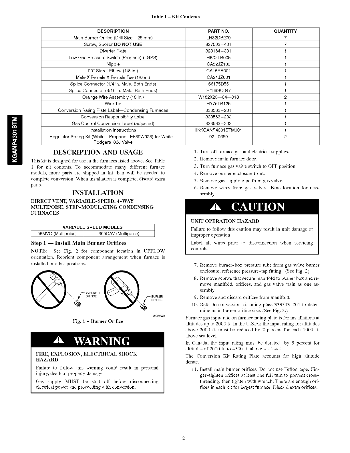
Table1- Kit Contents
DESCRIPTION PART NO. QUANTITY
Main Burner Orifice (Drill Size 1.25 mm) LH32DB209 7
Screw, Spoiler DO NOT USE 327593-401 7
Diverter Plate 323184-301 1
Low Gas Pressure Switch (Propane) (LGPS) HK02LB008 1
Nipple CA52JZ103 1
90 ° Street Elbow (1/8 in.) CA15RA001 1
Male X Female X Female Tee (1/8 in.) CA21JZ001 1
Splice Connector (1/4 in. Male, Both Ends) 66175D55 1
Splice Connector (3/16 in. Male, Both Ends) HY89SC047 1
Orange Wire Assembly (18 in.) W182X23 04 018 2
Wire Tie HY76TB125 1
Conversion Rating Plate Label Condensing Furnaces 333583-201 1
Conversion Responsibility Label 333583-203 1
Gas Control Conversion Label (adjusted) 333583-202 1
Installation Instructions IIKKGANP4301STMO01 1
Regulator Spring Kit (White Propane-EF39W023) for White- 92-0659 2
Rodgers 36J Valve
DESCRIPTION AND USAGE
This kit is designed for use in the furnaces listed above. See Table
1 for kit contents. To accommodate many different furnace
models, more parts are shipped in kit than will be needed to
complete conversion. When installation is complete, discard extra
parts.
INSTALLATION
DIRECT VENT, VARIABLE-SPEED, 4-WAY
MULTIPOISE, STEP-MODULATING CONDENSING
FURNACES
VARIABLE SPEED MODELS
58MVC (Multipoise) 355CAV (Multipoise)
Step 1-- Install Main Burner Orifices
NOTE: See Fig. 2 for component location in UPFLOW
orientation. Reorient component arrangement when furnace is
installed in other positions.
A96249
Fig. 1 - Burner Orifice
FIRE, EXPLOSION, ELECTRICAL SHOCK
HAZARD
Failure to follow this warning could result in personal
injury, death or property damage.
Gas supply MUST be shut off before disconnecting
electrical power and proceeding with conversion.
1. Turn off furnace gas and electrical supplies.
2. Remove main furnace door.
3. Turn furnace gas valve switch to OFF position.
4. Remove burner enclosure front.
5. Remove gas supply pipe from gas valve.
6. Remove wires from gas valve. Note location for reas-
sembly.
UNIT OPERATION HAZARD
Failure to follow this caution may result in unit damage or
improper operation.
Label all wires prior to disconnection when servicing
controls.
7. Remove burner-box pressure tube from gas valve burner
enclosure; reference pressure-tap fitting. (See Fig. 2).
8. Remove screws that secure manifold to burner box and re-
move manifold, orifices, and gas valve train as one as-
sembly.
9. Remove and discard orifices from manifold.
10. Refer to conversion kit rating plate 333583-201 to deter-
mine main burner orifice size. (See Fig. 3.)
Furnace gas input rate on furnace rating plate is for installations at
altitudes up to 2000 ft. In the U.S.A.; the input rating for altitudes
above 2000 ft. must be reduced by 2 percent for each 1000 ft.
above sea level.
In Canada, the input rating must be derated by 5 percent for
altitudes of 2000 ft. to 4500 ft. above sea level.
The Conversion Kit Rating Plate accounts for high altitude
derate.
11. Install main burner orifices. Do not use Teflon tape. Fin-
ger-tighten orifices at least one full turn to prevent cross-
threading, then tighten with wrench. There are enough ori-
fices in each kit for largest furnace. Discard extra orifices.
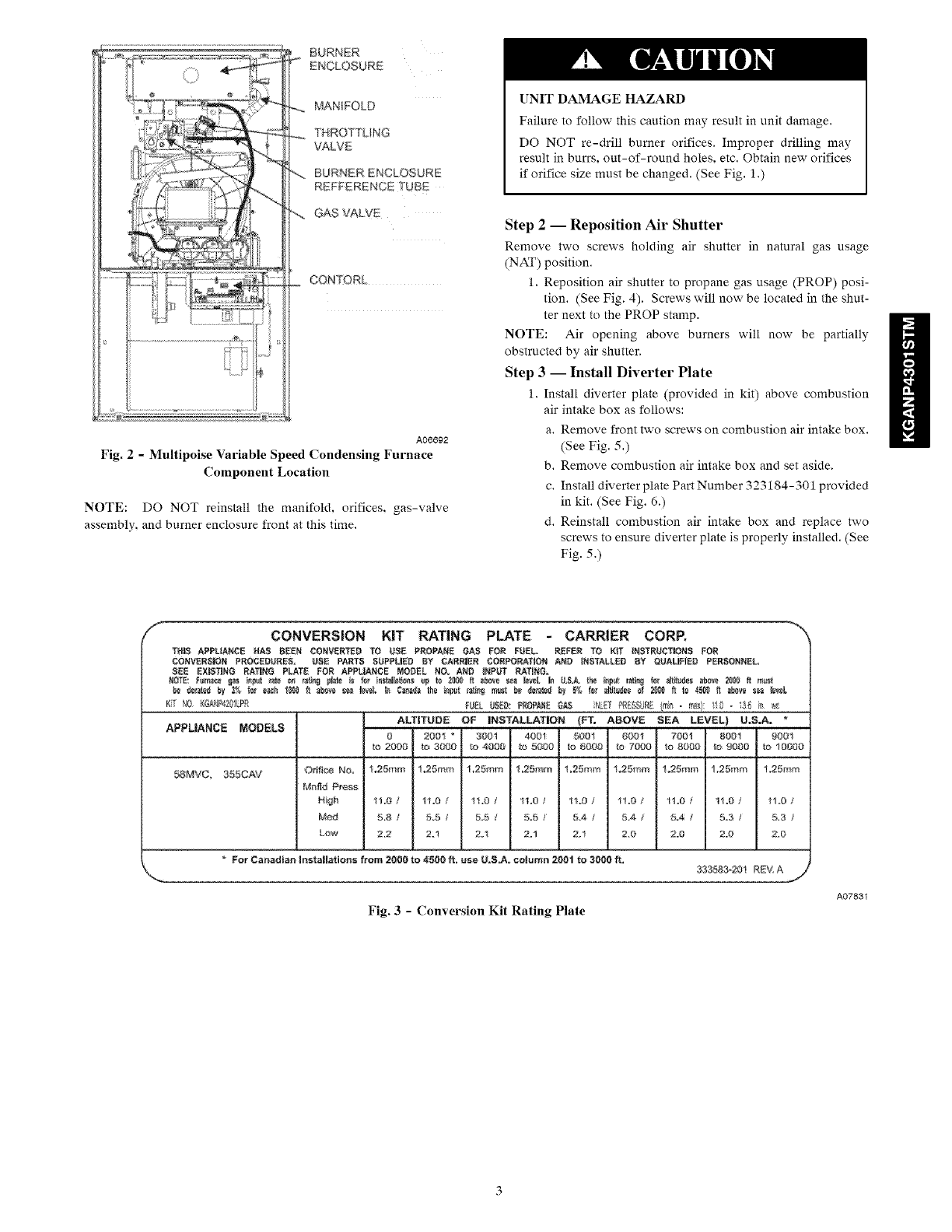
BURNER
D'4CLOSURE
MANIFOLD
THROTTLING
VALVE
BURNERENCLOSURE
REFFERENCETUBE
GAS VALVE
CONTORL
AO6692
Fig. 2 - Multipoise Variable Speed Condensing Furnace
Component Location
NOTE: DO NOT reinstall the manifold, orifices, gas-valve
assembly, and burner enclosure front at this time.
UNIT DAMAGE HAZARD
Failure to follow this caution may result in unit damage.
DO NOT re-drill burner orifices. Improper drilling may
result in burrs, out-of-round holes, etc. Obtain new orifices
if orifice size must be changed. (See Fig. 1.)
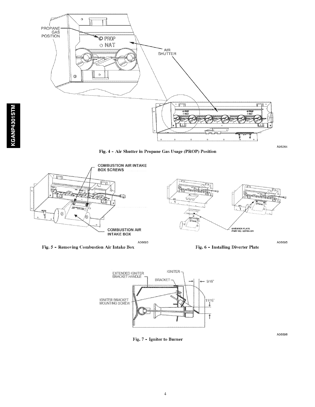
Step 2 -- Reposition Air Shutter
Remove two screws holding air shutter in natural gas usage
(NAT) position.
1. Reposition air shutter to propane gas usage (PROP) posi-
tion. (See Fig. 4). Screws will now be located in the shut-
ter next to the PROP stamp.
NOTE: Air opening above burners will now be partially
obstructed by air shutter.
Step 3 -- Install Diverter Plate
1. Install diverter plate (provided in kit) above combustion
air intake box as follows:
a. Remove front two screws on combustion air intake box.
(See Fig. 5.)
b. Remove combustion air intake box and set aside.
c. Install diverter plate Part Number 323184-301 provided
in kit. (See Fig. 6.)
d. Reinstall combustion air intake box and replace two
screws to ensure diverter plate is properly installed. (See
Fig. 5.)
f
/CONVERSION KIT RATING PLATE - CARRIER CORE
T_L_ APPUARCE HAS B_EN CONVERTED TO USE PEOPARE GA_ FOR FUEL REFER TO KiT _MSTRUCT_N_ FOR
CONVERt;lOB PROCEO_REE, USE PART5 SUPPLIED BY CARBIER CORPORATION AND [NETALLBB BY _JALFIEB PERSONNEL,
R;ED EXIR;TING EATING PLATE FOR; APPt3ANCE MODEL N0. AND iNPUT P,ATNG_
KT fi0KG#_P_Z_I_ F%L U_E0:PROPANEGAS N_T PRESSU,__ - ram::I - 3_ _ _'_
ALTITUDE OF INBTALLATION {FT, ABOVE S_A LEVEL) U,B.A, *
APPLIANC_ NOD_L8 0 2001 _ 3001 4001 5001 0001 7001 8001 _001
_0 2000 tO,3000 tO 4000 IO 5000 _o 6000 tO _OO0 tO 8000 I0 9000 _0 10000
58MVC, 355CAM Orifice No. %25mm !.25mm 1,25mm 1,25mm 1,25mm 1,25mm 1.25mm !.25mm 1,25mm
M_fld #ross
High 1%0 /1!.0 /!1.0 ¢11,0 /11.0 i11.0 /11.0 f11.0 /110 /
M_ 5.8 /5.5 /5.5 /5=5 _ 5.4 /5.4 /B=4 _ 5=3 /5.3
Low 2.2 2.! 2_1 2.1 2.1 2.0 2.0 2.0 2.13
ForCanadianinstalhtions from 2000to 4,500ft. useLI,R;J',.column200"tte 3000ft, :,'_33583,.20t REVA
Fig. 3 - Conversion Kit Rating Plate
A07831
!
GAS
POSITION PROP
o NAT
Fig. 4- Air Shutter in Propane Gas Usage (PROP) Position
A96264
A06693
Fig. 5- Removing Combustion Air Intake Box Fig. 6-Installing Diverter Plate
A06695
Fig. 7 - Igniter to Burner
A06_6
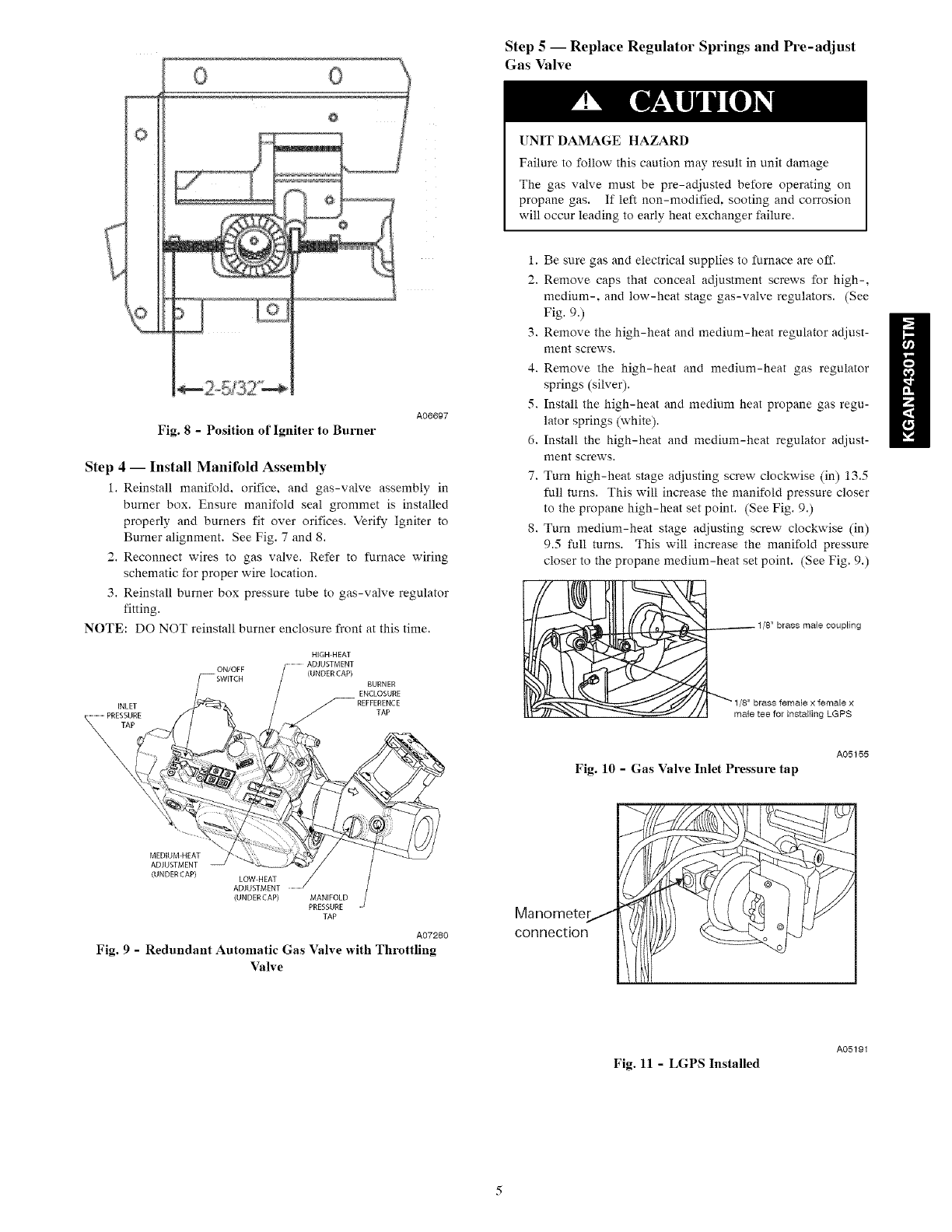
Fig. 8 - Position of Igniter to Burner
A06697
Step 4-- Install Manifold Assembly
1. Reinstall manifold, orifice, and gas-valve assembly in
burner box. Ensure manifold seal grommet is installed
properly and burners fit over orifices. Verify Igniter to
Burner alignment. See Fig. 7 and 8.
2. Reconnect wires to gas valve. Refer to furnace wiring
schematic for proper wire location.
3. Reinstall burner box pressure tube to gas-valve regulator
fitting.
NOTE: DO NOT reinstall burner enclosure front at this time.
INLET
PRESSURE
\
ON/OFF
NIGH HEAT
(UNDER CAP)
BURNER
ENCLOSURE
REFFERENCE
TAP
MEDIUM NEAT
ADJUSTMENT
(UNDERCAP) LOW HEAT /
ADJUSTMENT ...............
(UNDERCAP) MANIFOLD
PRESSURE
TAP
A07280
Fig. 9 -Redundant Automatic Gas Valve with Throttling
Valve
Step 5 -- Replace Regulator Springs and Pre-adjust
Gas Valve
UNIT DAMAGE HAZARD
Failure to follow this caution may result in unit damage
The gas valve must be pre-adjusted before operating on
propane gas. If left non-modified, sooting and corrosion
will occur leading to early heat exchanger failure.
1. Be sure gas and electrical supplies to furnace are off.
2. Remove caps that conceal adjustment screws for high-,
medium-, and low-heat stage gas-valve regulators. (See
Fig. 9.)
3. Remove the high-heat and medium-heat regulator adjust-
ment screws.
4. Remove the high-heat and medium-heat gas regulator
springs (silver).
5. Install the high-heat and medium heat propane gas regu-
lator springs (white).
6. Install the high-heat and medium-heat regulator adjust-
ment screws.
7. Turn high-heat stage adjusting screw clockwise (in) 13.5
full turns. This will increase the manifold pressure closer
to the propane high-heat set point. (See Fig. 9.)
8. Turn medium-heat stage adjusting screw clockwise (in)
9.5 full turns. This will increase the manifold pressure
closer to the propane medium-heat set point. (See Fig. 9.)
_8" brass male coupling
brass female x female x
male tee for installing LGPS
Fig. 10 - Gas Valve Inlet Pressure tap
A05155
Manomete__
connection _ _
Fig. 11 -LGPS Installed
A05191
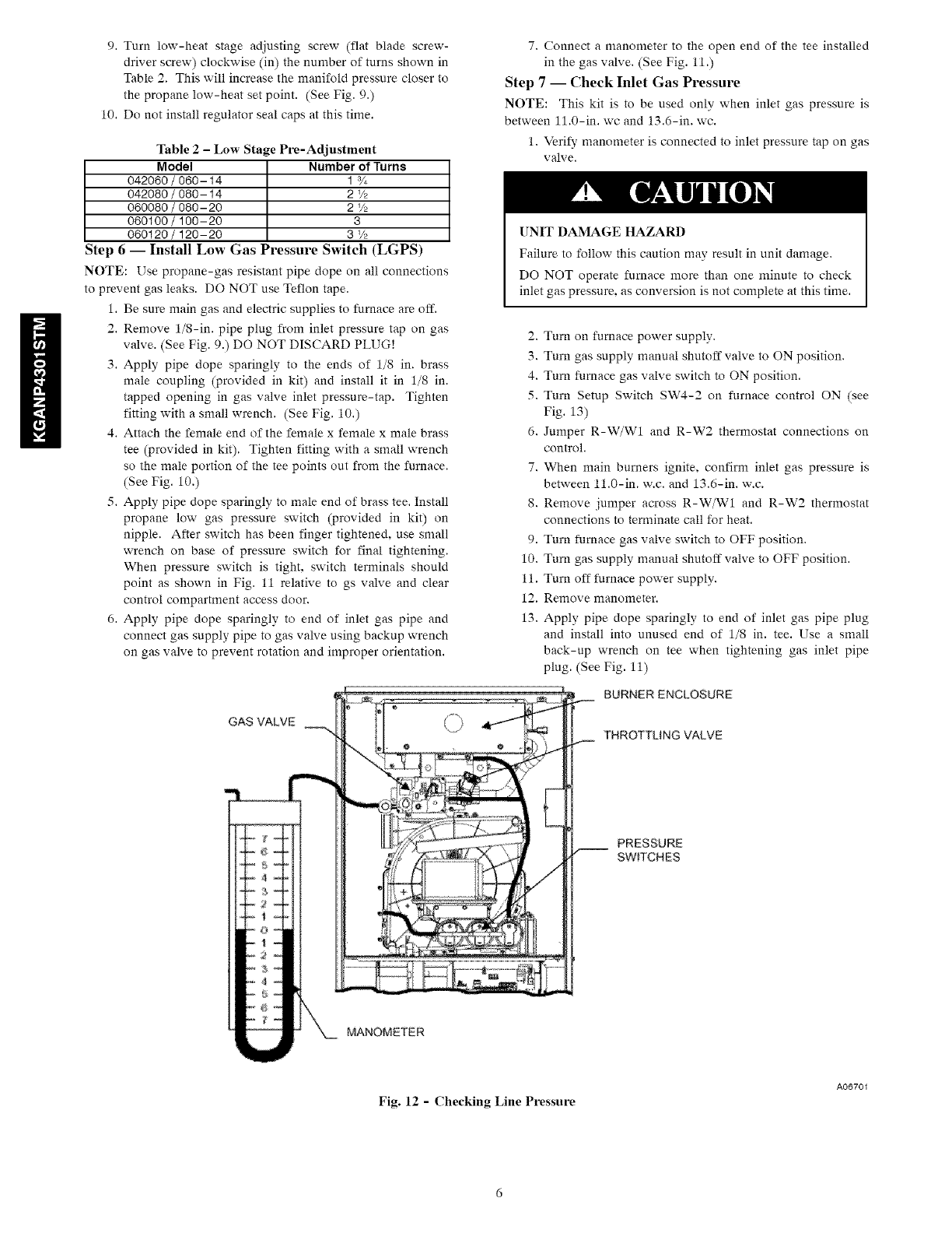
9. Turn low-heat stage adjusting screw (flat blade screw-
driver screw) clockwise (in) the number of turns shown in
Table 2. This will increase the manifold pressure closer to
the propane low-heat set point. (See Fig. 9.)
10. Do not install regulator seal caps at this time.
Table 2 -Low Stage Pie-Adjustment
Model Number of Turns
042060 /060-14 1%
042080 /080-14 2 Vz
060080 /080-20 2 _/z
060100 /100-20 3
060120 /120-20 3 _/_
Step 6 -- Install Low Gas Pressure Switch (LGPS)
NOTE: Use propane-gas resistant pipe dope on all connections
to prevent gas leaks. DO NOT use Teflon tape.
1. Be sure main gas and electric supplies to furnace are off.
2. Remove 1/8-in. pipe plug from inlet pressure tap on gas
valve. (See Fig. 9.) DO NOT DISCARD PLUG!
3. Apply pipe dope sparingly to the ends of 1/8 in. brass
male coupling (provided in kit) and install it in 1/8 in.
tapped opening in gas valve inlet pressure-tap. Tighten
fitting with a small wrench. (See Fig. 10.)
4. Attach the female end of the female x female x male brass
tee (provided in kit). Tighten fitting with a small wrench
so the male portion of the tee points out from the furnace.
(See Fig. 10.)
5. Apply pipe dope sparingly to male end of brass tee. Install
propane low gas pressure switch (provided in kit) on
nipple. After switch has been finger tightened, use small
wrench on base of pressure switch for final tightening.
When pressure switch is tight, switch terminals should
point as shown in Fig. 11 relative to gs valve and clear
control compartment access door.
6. Apply pipe dope sparingly to end of inlet gas pipe and
connect gas supply pipe to gas valve using backup wrench
on gas valve to prevent rotation and improper orientation.
7. Connect a manometer to the open end of the tee installed
in the gas valve. (See Fig. 11.)
Step 7-- Check Inlet Gas Pressure
NOTE: This kit is to be used only when inlet gas pressure is
between 11.0-in. wc and 13.6-in. wc.
1. Veri_, manometer is connected to inlet pressure tap on gas
valve.
UNIT DAMAGE HAZARD
Failure to follow this caution may result in unit damage.
DO NOT operate furnace more than one minute to check
inlet gas pressure, as conversion is not complete at this time.
GAS VALVE
-2_4
2. Turn on furnace power supply.
3. Turn gas supply manual shutoff valve to ON position.
4. Turn furnace gas valve switch to ON position.
5. Turn Setup Switch SW4-2 on furnace control ON (see
Fig. 13)
6. Jumper R-W/W1 and R-W2 thermostat connections on
control.
7. When main burners ignite, confirm inlet gas pressure is
between 11.0-in. w.c. and 13.6-in. w.c.
8. Remove jumper across R-W/W1 and R-W2 thermostat
connections to terminate call for heat.
9. Turn furnace gas valve switch to OFF position.
10. Turn gas supply manual shutoff valve to OFF position.
11. Turn off furnace power supply.
12. Remove manometer.
13. Apply pipe dope sparingly to end of inlet gas pipe plug
and install into unused end of 1/8 in. tee. Use a small
back-up wrench on tee when tightening gas inlet pipe
plug. (See Fig. 11)
MANOMETER
BURNER ENCLOSURE
THROTTLING VALVE
PRESSURE
SWITCHES
Fig. 12 -Checking Line Pressure
A06701
USERINTERFACE CONTINUOUSFAN SW4 SETU_
ORADVANCEO (OF)AI_LOW SWITCHES
PRODUCT SETUPSWITCHES OAT
MODEL PLUG MONFTO_ CONNECTOR
_LOWER O_ - " OAJ
DELAY
(A/C) AIR FlOW
SFUP SW_TCHES _'
115VAC (_2)NEUTRAL
CONNECTIONS
PEt LOWVOLTAGEMAFN _ EXAMPLE:
HARNESSCONNECTOR
soFrwAfl_ pART DATE
VERSION NUMBER COD_
NUM_
\
VOLTA_ CONNECTIONS
Fig. 13 - Furnace Control
HUMIDIFIER
TEflM_NAL(2_VAC
0,5 AMPMA×,
CONDmONING
RELAYD_SABLE
JUMPE_
CONNECTOR
(FACTORY
ONLY)
\ PL3 ECMB_OWE_
HARNESS
N_ONNECTO_
NUMBER
PL2 HOTSURFACE
_GNITE__INOUCER
MOTORCONNECTOR
A07422
Step 8 -- Pressure Switch Wiring (refer to furnace
wiring diagram)
1. Disconnect orange wire from low-heat pressure switch
LPS on inducer housing.
2. Connect uninsulated terminal of one orange wire (pro-
vided in kit) to splice connector. Connect other end to C
terminal on low gas pressure switch LGPS. Connect the
other end of the splice connector to the orange wire dis-
connected in Step 1.
3. Connect insulated terminal of second orange wire (pro-
vided in kit) to N.O. terminal on low gas pressure switch
LGPS. Connect other end to pressure switch LPS located
on inducer housing.
4. Route orange wires along wire harness. If possible, secure
with wire tie provided in kit.
Step 9 -- Check Furnace Operation and Make
Necessary Adjustments
1. Be sure main gas and electric supplies to furnace are off.
2. Remove 1/8-in. pipe plug from manifold pressure tap on
throttling valve. (See Fig. 9.)
3. Attach manometer to manifold pressure tap on throttling
valve (See Fig. 14.)
4. Turn gas supply manual shutoff valve to ON position.
5. Turn furnace gas valve switch to ON position.
6. Check all threaded pipe connections for gas leaks.
7. Turn on furnace power supply.
Step 10 -- Gas Input Rate Information
The gas-input rate for propane is the same as for natural gas. See
furnace rating plate (Fig. 16) for input rate. The input rate for
propane is determined by manifold pressure and orifice size (See
Fig. 3.) The gas-valve regulator must be set for high heat first,
then medium heat and then set for low heat.
NOTE: Manifold pressure MUST always be measured with the
burner enclosure front REMOVED. (See Fig. 2.) Furnace gas
input rate on rating plate is for installations at altitudes up to 2000
ft.
In the U.S.A.. the input rating for altitudes above 2000 ft. must be
reduced by 2 percent for each 1000 ft. above sea level.
In Canada, the input rating must be derated by 5 percent for
altitudes of 2000 ft. to 4500 ft. above sea level.
The Conversion Kit Rating Plate accounts for high altitude
derate.
Step 11 -- Set Gas Input Rate
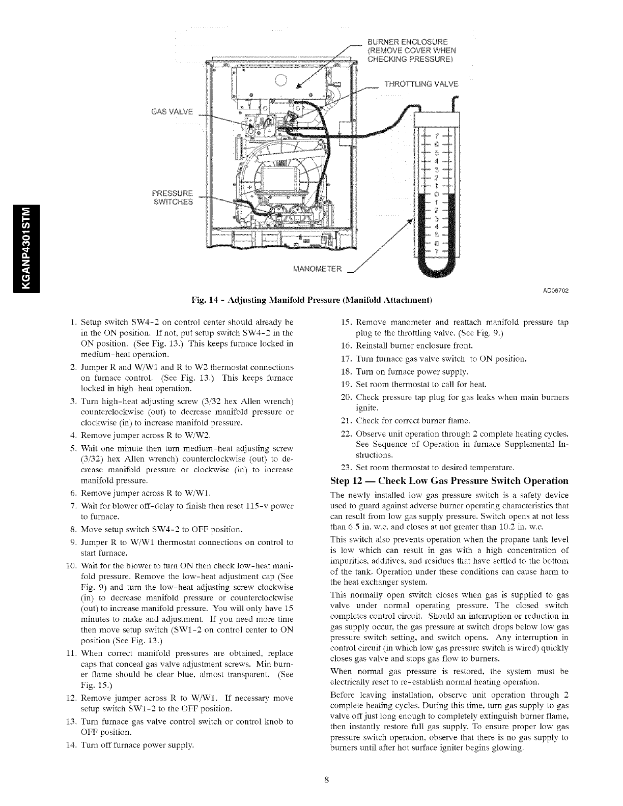
BURNER ENCLOSURE
(REMOVE COVBR WHEN
CHECKING PRESSURE}
GAS VALVE
THROTTLING VALVE
MANOMETER
AD06702
Fig. 14 - Adjusting Manifold Pressure (Manifold Attachment)
1. Setup switch SW4-2 on control center should already be
in the ON position. If not, put setup switch SW4-2 in the
ON position. (See Fig. 13.) This keeps furnace locked in
medium-heat operation.
2. Jumper R and W/W1 and R to W2 thermostat connections
on furnace control. (See Fig. 13.) This keeps furnace
locked in high-heat operation.
3. Turn high-heat adjusting screw (3/32 hex Allen wrench)
counterclockwise (out) to decrease manifold pressure or
clockwise (in) to increase manifold pressure.
4. Remove jumper across R to W/W2.
5. Wait one minute then turn medium-heat adjusting screw
(3/32) hex Allen wrench) counterclockwise (out) to de-
crease manifold pressure or clockwise (in) to increase
manifnld pressure.
6. Remove jumper across R to W/W1.
7. Wait for blower off-delay to finish then reset 115-v power
to furnace.
8. Move setup switch SW4-2 to OFF position.
9. Jumper R to W/W1 thermostat connections on control to
start furnace.
10. Wait for the blower to turn ON then check low-heat mani-
fold pressure. Remove the low-heat adjustment cap (See
Fig. 9) and turn the low-heat adjusting screw clockwise
(in) to decrease manifold pressure or counterclockwise
(out) to increase manifold pressure. You will only have 15
minutes to make and adjustment. If you need more time
then move setup switch (SW1-2 on control center to ON
position (See Fig. 13.)
11. When correct manifold pressures are obtained, replace
caps that conceal gas valve adjustment screws. Min burn-
er flame should be clear blue. almost transparent. (See
Fig. 15.)
12. Remove jumper across R to W/W1. If necessary move
setup switch SW1-2 to the OFF position.
13. Turn furnace gas valve control switch or control knob to
OFF position.
14. Turn off furnace power supply.
15. Remove manometer and reattach manifold pressure tap
plug to the throttling valve. (See Fig. 9.)
16. Reinstall burner enclosure front.
17. Turn furnace gas valve switch to ON position.
18. Turn on furnace power supply.
19. Set room thermostat to call for heat.
20. Check pressure tap plug for gas leaks when main burners
ignite.
21. Check for correct burner flame.
22. Observe unit operation through 2 complete heating cycles.
See Sequence of Operation in furnace Supplemental In-
structions.
23. Set room thermostat to desired temperature.
Step 12 -- Check Low Gas Pressure Switch Operation
The newly installed low gas pressure switch is a safety device
used to guard against adverse burner operating characteristics that
can result from low gas supply pressure. Switch opens at not less
than 6.5 in. w.c. and closes at not greater than 10.2 in. w.c.
This switch also prevents operation when the propane tank level
is low which can result in gas with a high concentration of
impurities, additives, and residues that have settled to the bottom
of the tank. Operation under these conditions can cause harm to
the heat exchanger system.
This normally open switch closes when gas is supplied to gas
valve under normal operating pressure. The closed switch
completes control circuit. Should an interruption or reduction in
gas supply occur, the gas pressure at switch drops below low gas
pressure switch setting, and switch opens. Any interruption in
control circuit (in which low gas pressure switch is wired) quickly
closes gas valve and stops gas flow to burners.
When normal gas pressure is restored, the system must be
electrically reset to re-establish normal heating operation.
Before leaving installation, observe unit operation through 2
complete heating cycles. During this time, turn gas supply to gas
valve off just long enough to completely extinguish burner flame.
then instantly restore full gas supply. To ensure proper low gas
pressure switch operation, observe that there is no gas supply to
burners until after hot surface igniter begins glowing.
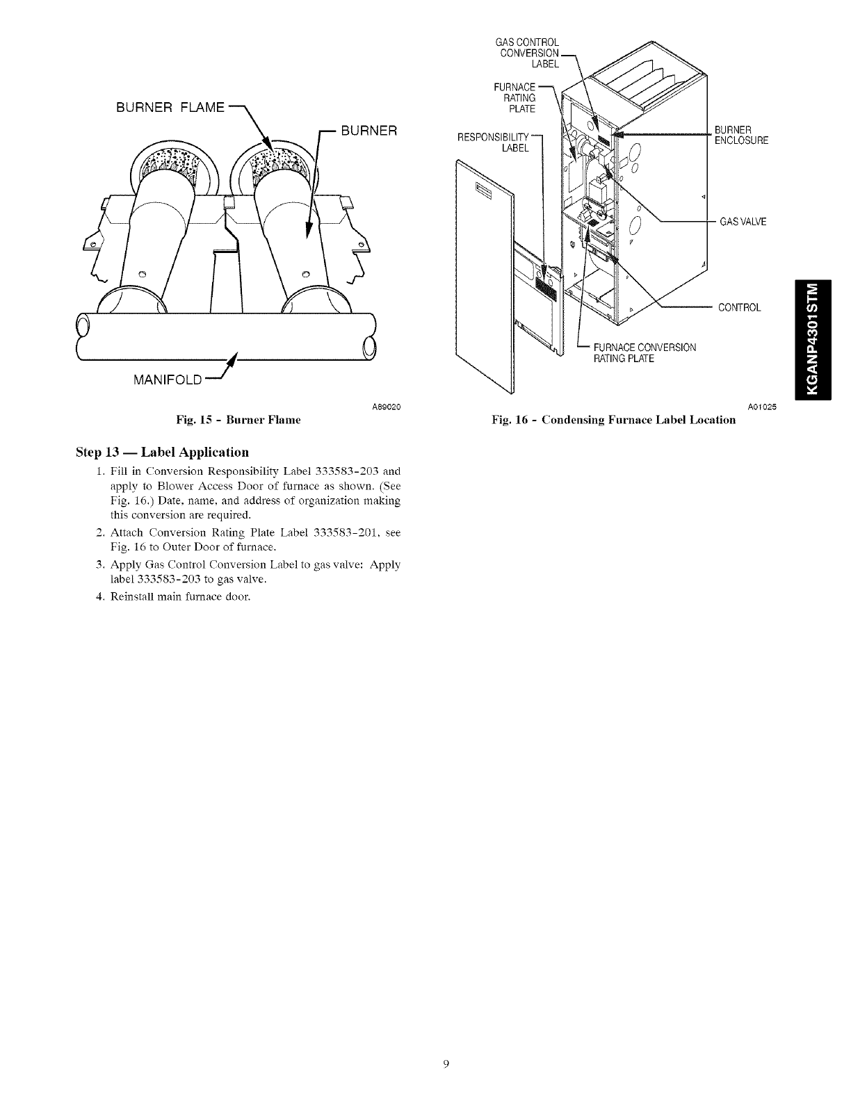
BURNER FLAME
BURNER
MANIFOLD
Fig. 15 - Burner Flame
A89020
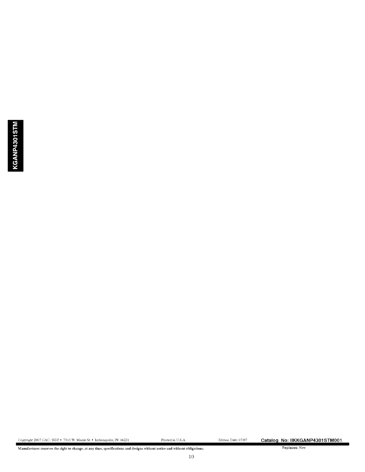
Step 13 -- Label Application
1. Fill in Conversion Responsibility Label 333583-203 and
apply to Blower Access Door of furnace as shown. (See
Fig. 16.) Date. name. and address of organization making
this conversion are required.
2. Attach Conversion Rating Plate Label 333583-201, see
Fig. 16 to Outer Door of furnace.
3. Apply Gas Control Conversion Label to gas valve: Apply
label 333583-203 to gas valve.
4. Reinstall main furnace door.
GASCONTROL
LABEL
RATING
PLATE
LABEL
FURNACECONVERSION
RATINGPLATE
BURNER
ENCLOSURE
-GASVALVE
CONTROL
A01025
Fig. 16 -Condensing Furnace Label Location
Copyright 2007 CAC BDP • 73t0 W Molds St • Indianapolis, IN 46231 Pdi_ted in USA
Manufacturer rese_'es the tight to change, at any time. specifications and designs without notice and without obllgatlolls.
Catalo_ No: IIKKGANP4301STM001
Rep_aoes: New
10
