CARRIER Home Generator Manual L0810472
User Manual: CARRIER CARRIER Home Generator Manual CARRIER Home Generator Owner's Manual, CARRIER Home Generator installation guides
Open the PDF directly: View PDF ![]() .
.
Page Count: 20

Air=cooled Generator
tery C
Installation Guidelines
TABLE
o___F
CONTENTS
Table of Contents
Table of Contents ................................inside Front Cover
Section | - General information ............................... IFC
1.1 Introduction .......................................................... IF(;
1.2 Battery Charger Compatibility ................................. 1
1.2.1 Determination of Generator/Translkr
Switch Model Type ........................................ 1
Section 2 -Load Shed Transfer Switch
Installation .................................................... 2
2.1 Load Shed Transl_r Switch (RTSS) Installation ...... 2
2.1.1 Wiring and Connections at the
Translkr Switch ............................................. 2
2.1.2 Wiring and Connections at the Generator ...... 2
2.1.3 Operational Testing ....................................... 2
Section 3 - Standard or Service Entrance Transfer
Switch installation ...................................... 3
3.1 Standard Transl_r Switch (RTSN) or (RTSE) Service
Entrance Rated Transl_r Switch Installation ........... 3
3.1.1 Wiring and Connections at the
3.1.2
3.1.3
3.1.4
Section 4
4.1.1
4.1.2
4.1.3
4.1.4
Section 5
Section 6
Translkr Switch ............................................. 3
Charger Mounting .......................................... 4
Wiring and Connections at the Generator ...... 5
Operational Testing ....................................... 6
-GenReady installation ................................. 6
Wiring and Connections at the
Translkr Switch ............................................. 6
Charger Mounting .......................................... 7
Wiring and Connections at the Generator ...... 7
Operational Testing ....................................... 8
-Interconnection Diagrams ..........................9
-Notes .............................................................16
For authorized service, reference
the dealer Iocator number found
in the generatorowner's manual
or on the generator.
1.1 iNTRODUCTiON
This battery charger supplies a trickle charging cur-
rent and voltage to maintain the charge on the gen-
erator starting battery inside the generator enclosure.
The charger will not replenish a fully discharged bat-
tery. It is intended to be connected to a 120VAC gen-
erator backed-up circuit only. If it is not connected
to a generator backed-up circuit the battery could go
"dead" while the generator is running for extended
periods of time.
Figure 1.1 -- Charger as Supplied indicating
input and Output Wiring
AC Input DC Output
_WARNING _"
Z_ This battery charger must be properly installed
and wired for correct operation of all 2008
model line Air-cooled Standby Generators.
Failure to do so will result in a dead battery
condition at the generator.
NOTE:
This installation guide should be used in conjunc-
tion with the "Installation and Owner's Manual"
that is furnished with the Air-cooled Standby
Generator and the Installation and appropriate
transfer switch manual. Please review all manuals
prior to installation of the generator and transfer
switch. This battery charger is not required with
the Liquid-cooled Generator product line. This
battery charger is not required for Air-cooled
Standby Generators prior to the 2008 model line.
This unit is not compatible with other generator
manufacturer's products.
Section 1- General Information
Battery ChargerInstallation Guidelines GENERAL
NFORMATON
These Installation Guidelines are designed to famil-
iarize personnel with the installation process for the
battery charger required for the air-cooled generator
only. It does not replace or supersede any information
contained in any of the written documents shipped
with the unit. This booklet should only be used in
conjunction with the Owner's Manual, Installation
Guide and other technical documents shipped with
the unit.
Future product updates and/or modifications will be
reflected in the written documentation included with
the equipment. Always read all accompanying docu-
mentation carefully before attempting to install any
generator, transfer switch or related equipment.
NOTE:
It is essential to comply with all regulations estab-
lished by the Occupational Safety and Health
Administration (OSHA) and strict adherence to all
local, state and national codes is mandatory.
This device should be installed with all local
electrical codes and/or the latest edition of the
National Electrical Code. All wiring must be the
correct size and type, and must conform to local
codes, standards, and regulations.
1.2 BATTERY CHARGER
COMPATiBiLiTY
This battery charger is compatible, and required with
all 2008 model line Air-cooled Standby Generators.
For all generators that were supplied with a transfer
switch/load center, the charger is already installed in
the transfer switch enclosure and this charger is not
needed. For all generators that were NOT supplied
with a transfer switch!load center, the charger is NOT
already installed and MUST be installed according to
these guidelines.
•1.2.1 DETERMiNATiON OF GENERATOR/
TRANSFERSWITCH MODEL TYPE
The Battery charger included with this manual only
needs to be used with certain transfer switch configu-
rations. Some transfer switch configurations already
have the battery charger installed in the transfer
switch. Before proceeding it is necessary to select the
transfer switch used from the following table.
Switch Type Switch Description Notes Proceed to Section
RTSD Pre-wire with 8 circuit load Battery charger is included and pre-wired with
the translkr switch. Discard this charger. No Stop Here
center further installation is required
RTSF Pre-wire with 10 circuit Battery charger is included and pre-wired with
the translkr switch. Discard this charger. No Stop Here
ST100R10C load center further installation is required
Pre-wire with 12 circuit Battery charger is included and pre-wired with
RTSH load center the translkr switch. Discard this charger. No Stop Here
further installation is required
RTSP Pre-wire with 14 circuit Battery charger is included and pre-wired with
the translkr switch. Discard this charger. No Stop Here
ST100R14C load center further installation is required
RTSW Pre-wire with 16 circuit Battery charger is included and pre-wired with
ST100R16C load center the translkr switch. Discard this charger. No Stop Here
KGATX0216100 further installation is required
RTSS Power Manager LTS -Load Battery charger is included with the transikr
KGALT0101200 Shed with 16 circuit load 2
switch. Proceed with connections.
SR200RDPM center
RTSN
SRXXXR Standard The included battery charger must be installed 3
and connected
KGATX
RTSE The included battery charger must be installed
SRXXXRD Service Entrance Rated 3
KGATD and connected
005448-0 The included battery charger must be installed 4
005449-0 GenReady and connected
KGATD0101RSP
NOTE: Switch Type is the first four (4) digits of the model number and can be found on the data label inside the switch.
q
INSTALLATION Section 2-Load Shed Transfer Switch Installation
Battery Charger Installation Guidelines
2.] LOAD SHED TRANSFERSWITCH
(RTSS)INSTALLATION
•2.1.] WIRING AND CONNECTIONS AT THE
TRAN_
Connect the 15B, 0, and 23 low voltage control wires
to the load shed controller connector J5 per the wir-
ing diagram. Wires should be sized according to the
following table.
CHARGER DC OUTPUT {TRANSFER SWITCH
TO GENERATOR) WIRE SIZE CHART
Maximum Wire Run Recommended Wire
Length Size (stranded copper)
35 feet (10.67m) No. 16 AWG.
60 feet (18.29m) No. 14 AWG.
90 feet (27.43m) No. 12 AWG.
NOTE:
The charger is already mounted in the transfer
switch (Figure 2, I).
NOTE:
See RTSS Installation/Wiring Diagram in the
"Interconnection Diagrams" section for connec-
tions.
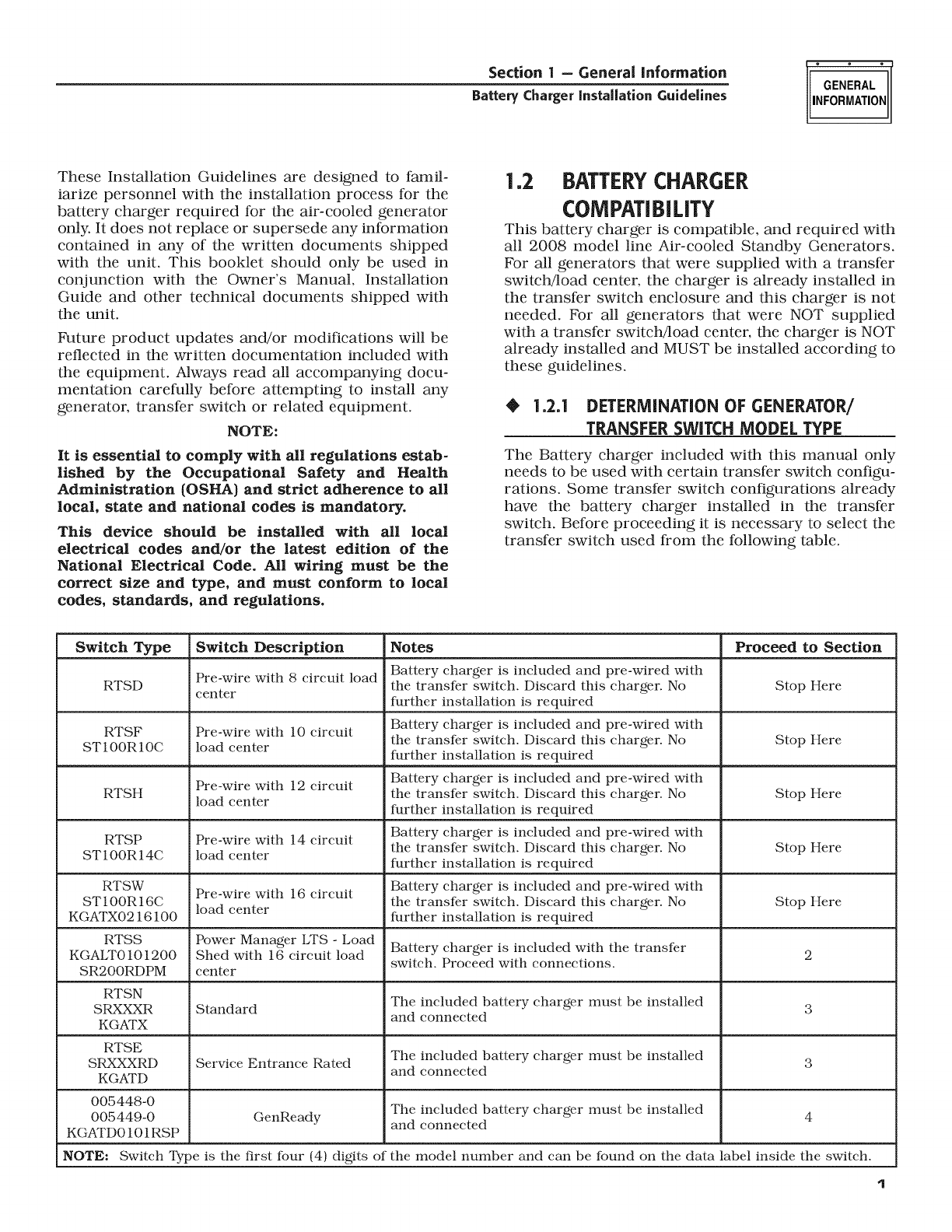
Figure 2.1 -- Wiring Connections at the Transfer
Switch
Charger
•2.1.2 WIRING AND CONNECTIONS AT THE
_ENERATO_
1. Crimp spade lugs onto all three low voltage wires,
15B, 0, and 23 (Purchased or supplied separate-
ly).
2. Connect the low voltage wires, 15B, 0, and 23 to
the terminal strip on the controller (Figure 2.2).
Figure 2.2 -- Connection of Charger DC Output
Wires in Generator Control Panel
2.]. PERATI NAL TE TiN
1. If already connected, disconnect the battery in
the generator. Remove the negative cable first fol-
lowed by the positive cable. Take care not to short
the cables together.
2. Ensure power is applied to the battery charger
input.
3. Connect a volt meter across the battery leads.
The voltage reading should be between 12.8 VDC
and 13.8 VDC (Figure 2.3).
Figure 2.3 -- Measurement of Charger Output
with Battery Disconnected
2
Section 3 =Standard or Service Entrance Transfer Switch Installation
Battery ChargerInstallation Guidelines
iNSTALLATiON
4. If the voltage is within range installation of the
battery charger is complete. If the voltage is not
within range verify all wiring and sizing and
retest.
5. Re-connect the battery cables. Positive cable first
followed by the negative cable.
3.1 STANDARD TRANSFER SWITCH
(RTSN)OR(RTSE)SERVICE
ENTRANCE RATED TRANSFER
SWITCH INSTALLATION
•3.]A WiRiNG AND CONNECTIONS AT THE
TRANSFER SWITCH
Choose the appropriate option.
NOTE:
See the appropriate RTSN or RTSE Installation/
Wiring Diagram in the "Interconnection Diagrams"
section for connections.
Option ] - Protected Load Provided in Load
Center
1. Install a 15Abreaker in the load center (Purchased
or supplied separately). The breaker must be on
a generator backed-up circuit or the battery in
the generator will not maintain its charge during
extended run periods.
2. Run the 120VAC hot wire and neutral wires to the
generator.
NOTE:
See the appropriate RTSN or RTSE Installation/
Wiring Diagram in the "Interconnection Diagrams"
section for connections.
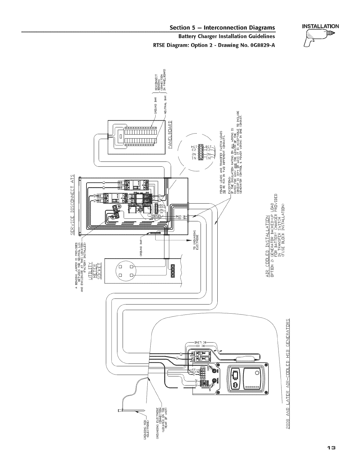
Option 2 - Protected Load Provided in the RTS,
Fuse Block Installation
NOTE:
This section is only appropriate for 2008 RTSN or
RTSE transfer switches,
1. Mount the optional 5amp 600V fuse and holder
in the transfer switch. (Purchased or supplied
separately). Pre-2008 transfer switches will not
have holes pre-drilled for the fuse holder. In this
case, it is necessary to drill holes in the enclosure
to mount the fuse holder (see Figures 3.1 and
3.4).
2. Connect one side of the fuse to terminal (T1) of
the transfer switch using a spade lug. Pre-2008
transfer switches will not have the spade lug
attached to terminal T1. The spade terminal is
available separately if required (see Figures 3.2
and 3.4).
3. Run the other side of the fuse holder 120VAC
Hot) along with the neutral from the neutral lug
to the generator (see Figures 3.1 and 3.5).
NOTE:
See the appropriate RTSN or RTSE Installation/
Wiring Diagram for connections,
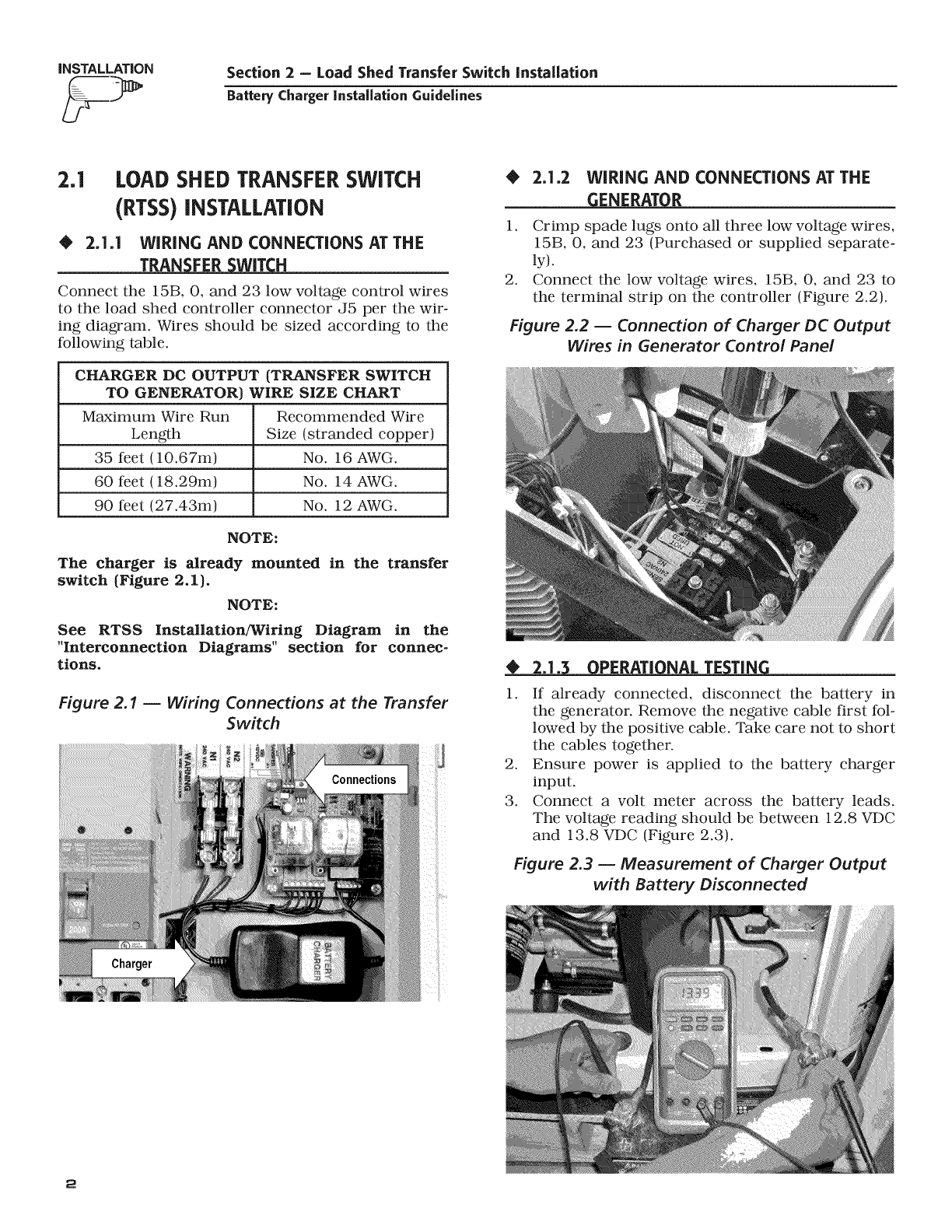
Figure 3.1 -- RTSN Fuse Block installation and
Neutral Connection
)
Figure 3.2 -- RTSN Fuse Block installation T1
Connection
3
iNSTALLATION Section 3 -Standard or Service Entrance Transfer Switch installation
Battery Charger Installation Guidelines
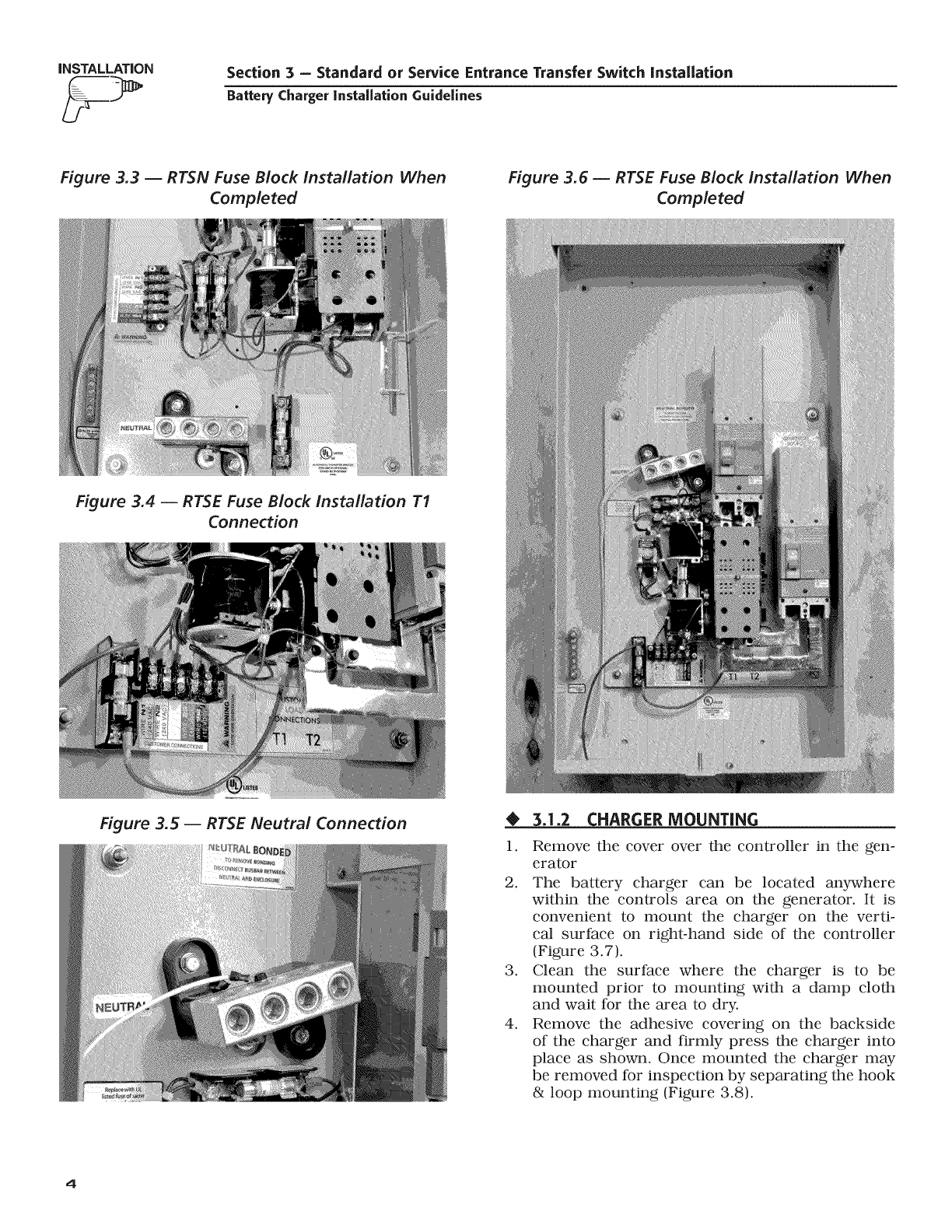
Figure 3.3 -- RTSN Fuse Block installation When
Completed
Figure 3.6 -- RTSE Fuse Block Installation When
Completed
Figure 3.4 -- RTSE Fuse Block installation T1
Connection
Figure 3.5 -- RTSE Neutral Connection •3.1.2 CHARGER MOUNTING
1. Remove the cover over the controller in the gen-
erator
2. The battery charger can be located anywhere
within the controls area on the generator. It is
convenient to mount the charger on the verti-
cat surface on right-hand side of the controller
(Figure 3.7).
3. Clean the surface where the charger is to be
mounted prior to mounting with a damp cloth
and wait for the area to dry.
4. Remove the adhesive covering on the backside
of the charger and firmly press the charger into
place as shown. Once mounted the charger may
be removed for inspection by separating the hook
& loop mounting (Figure 3.8).
4
Section 3 =Standard or Service Entrance Transfer Switch Installation
Battery ChargerInstallation Guidelines
iNSTALLATiON
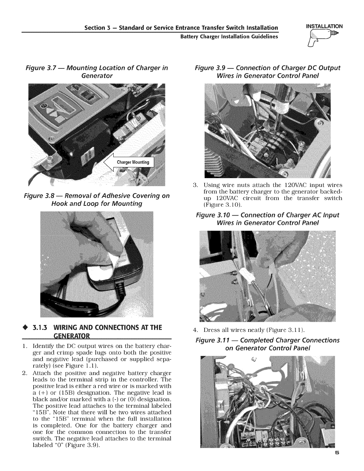
Figure 3.7 -- Mounting Location of Charger in
Generator
Figure 3.9 -- Connection of Charger DC Output
Wires in Generator Centre/Panel
Figure 3.8- Removal of Adhesive Covering on
Hook and Loop for Mounting
.Using wire nuts attach the 120VAC input wires
from the battery charger to the generator backed-
up 120VAC circuit from the transfer switch
(Figure 3.10).
Figure 3.10 -- Connection of Charger AC Input
Wires in Generator Control Pane/
•3.1.3 WIRING AND CONNECTIONS AT THE
_ENERATOR
1.
.
Identify the DC output wires on the battery char-
ger and crimp spade lugs onto both the positive
and negative lead (purchased or supplied sepa-
rately) (see Figure 1.1).
Attach the positive and negative battery charger
leads to the terminal strip in the controller. The
positive lead is either a red wire or is marked with
a (+) or (15B) designation. The negative lead is
black and/or marked with a (-) or (0) designation.
The positive lead attaches to the terminal labeled
"15B". Note that there will be two wires attached
to the "15B" terminal when the full installation
is completed. One for the battery charger and
one for the common connection to the transfer
switch. The negative lead attaches to the terminal
labeled "0" (Figure 3.9).
4. Dress all wires neatly (Figure 3.11).
Figure 3.11 -- Completed Charger Connections
on Generator Control Panel
Q_
INSTALLATION Section 4- GenReady Installation
Battery Charger installation Guidelines
NOTE:
See the appropriate RTSN or RTSE Installation/
Wiring Diagram in the "Interconnection Diagrams"
section for connections.
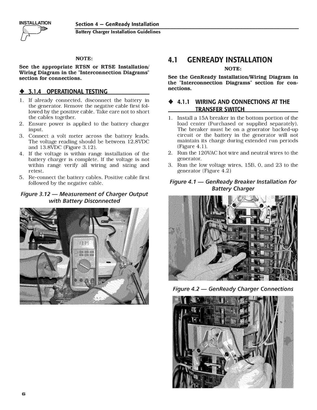
OPERATIONAL TESTING
If already connected, disconnect the battery in
the generator. Remove the negative cable first fol-
lowed by the positive cable. Take care not to short
the cables together.
2. Ensure power is applied to the battery charger
input.
3. Connect a volt meter across the battery leads.
The voltage reading should be between 12.8VDC
and 13.8VDC (Figure 3.12).
4. If the voltage is within range installation of the
battery charger is complete. If the voltage is not
within range verify all wiring and sizing and
retest.
5. Re-connect the battery cables. Positive cable first
followed by the negative cable.
Figure 3.12 -- Measurement of Charger Output
with Battery Disconnected
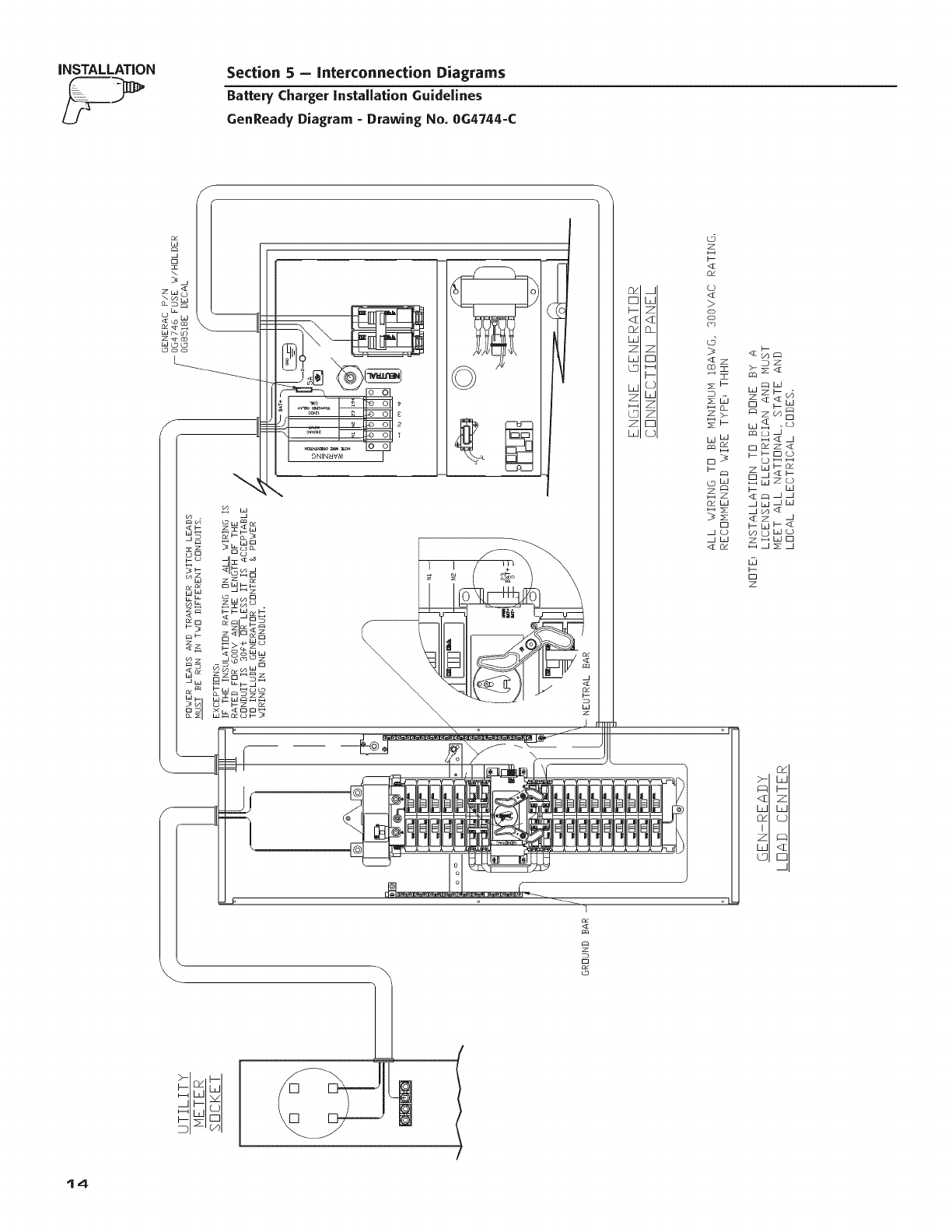
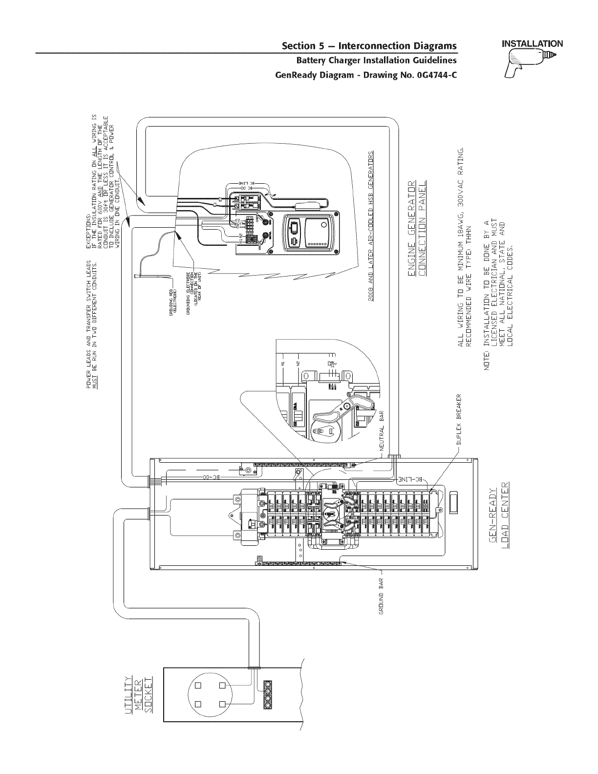
4.1 GENREADYINSTALLATION
NOTE:
See the GenReady Installation/Wiring Diagram in
the "Interconnection Diagrams" section for con-
nections.
4.1.1 WiRiNG AND CONNECTIONS AT THE
TRAN_
1. Install a 15A breaker in the bottom portion of the
load center (Purchased or supplied separately).
The breaker must be on a generator backed-up
circuit or the battery in the generator will not
maintain its charge during extended run periods
(Figure 4.1 ).
2. Run the 120VAC hot wire and neutral wires to the
generator.
3. Run the low voltage wires, 15B, 0, and 23 to the
generator (Figure 4.2)
Figure 4.1 -- GenReady Breaker Installation for
Battery Charger
Figure 4.2 -- GenReady Charger Connections
6
Section 4 - GenReady Installation
Battery ChargerInstallation Guidelines
iNSTALLATiON
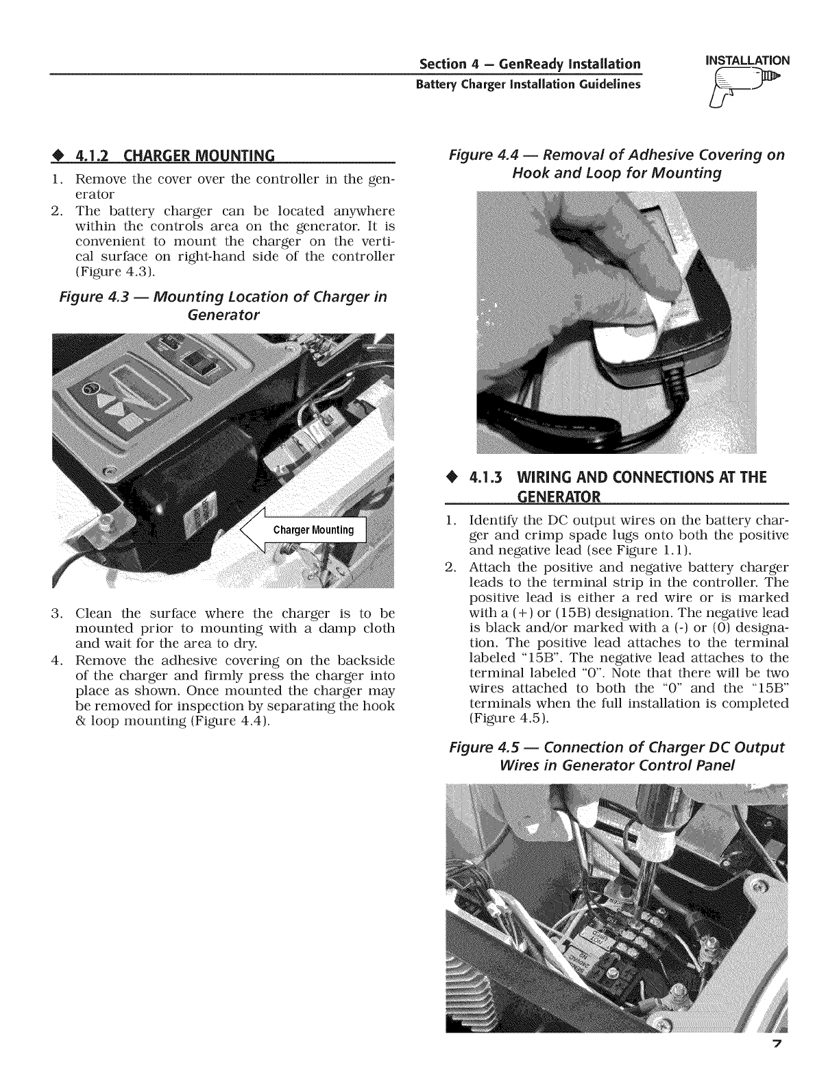
O4.1.2 CHARGER MOUNTING
1.
2.
Remove the cover over the controller in the gen-
erator
The battery charger can be located anywhere
within the controls area on the generator. It is
convenient to mount the charger on the verti-
cal surface on right-hand side of the controller
(Figure 4.3).
Figure 4.3 -- Mounting Location of Charger in
Generator
Figure 4.4 -- Removal of Adhesive Covering on
Hook and Loop for Mounting
.
4.
Clean the surface where the charger is to be
mounted prior to mounting with a damp cloth
and wait for the area to dry.
Remove the adhesive covering on the backside
of the charger and firmly press the charger into
place as shown. Once mounted the charger may
be removed for inspection by separating the hook
& loop mounting (Figure 4.4).
1.
.
4.1.3 WIRING AND CONNECTIONS AT THE
GENERATOR
Identify the DC output wires on the battery char-
ger and crimp spade lugs onto both the positive
and negative lead (see Figure 1.1).
Attach the positive and negative battery charger
leads to the terminal strip in the controller. The
positive lead is either a red wire or is marked
with a (+) or (15B) designation. The negative lead
is black and/or marked with a (-) or (0) designa-
tion. The positive lead attaches to the terminal
labeled "15B". The negative lead attaches to the
terminal labeled "0". Note that there will be two
wires attached to both the "0" and the "15B"
terminals when the full installation is completed
(Figure 4.5).
Figure 4.5 -- Connection of Charger DC Output
Wires in Generator Control Panel
7
INSTALLATION Section 4 - GenReady Installation
Battery Charger instaUationGuidelines
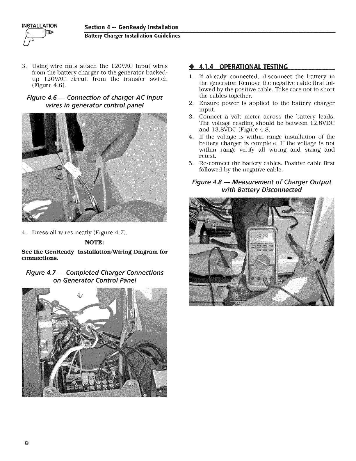
.Using wire nuts attach the 120VAC input wires
from the battery charger to the generator backed-
up 120VAC circuit from the transfer switch
(Figure 4.6).
Figure 4.6 -- Connection of charger AC input
wires in generator control panel
_J_DPERATI NAL TE TIN
1. If already connected, disconnect the battery in
the generator. Remove the negative cable first fol-
lowed by the positive cable. Take care not to short
the cables together.
2. Ensure power is applied to the battery charger
input.
3. Connect a volt meter across the battery leads.
The voltage reading should be between 12.8VDC
and 13.8VDC (Figure 4.8.
4. If the voltage is within range installation of the
battery charger is complete. If the voltage is not
within range verify all wiring and sizing and
retest.
5. Re-connect the battery cables. Positive cable first
followed by the negative cable.
Figure 4.8 -- Measurement of Charger Output
with Battery Disconnected
4. Dress all wires neatly (Figure 4.7).
NOTE:
See the GenReady Installation/Wiring Diagram for
connections.
Figure 4.7 -- Completed Charger Connections
on Generator Control Panel
8

Section 5 - Interconnection Diagrams
Battery Charger installation Guidelines
RTSS Diagram - Drawing No. 0G8774-A
iNSTALLATION
\
®
z
W
<E
z
W
W_
®
ow
z_
Ow
\
<I
9
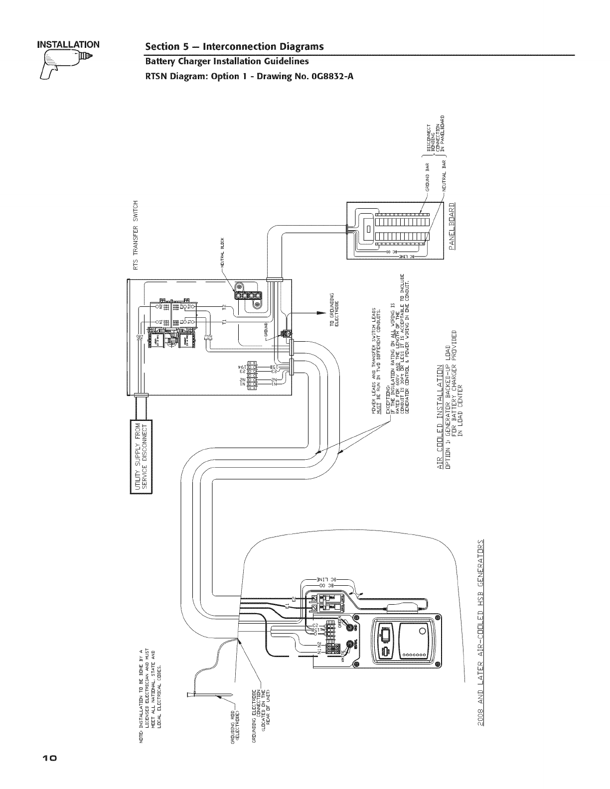
INSTALLATION Section 5 - Interconnection Diagrams
Battery Charger installation Guidelines
RTSN Diagram: Option 1- Drawing No. 0G8832-A
z
_zg8
w_ o
m_u
_dd
mm
mm_
<z @
_m
au_8
0
<_
Io
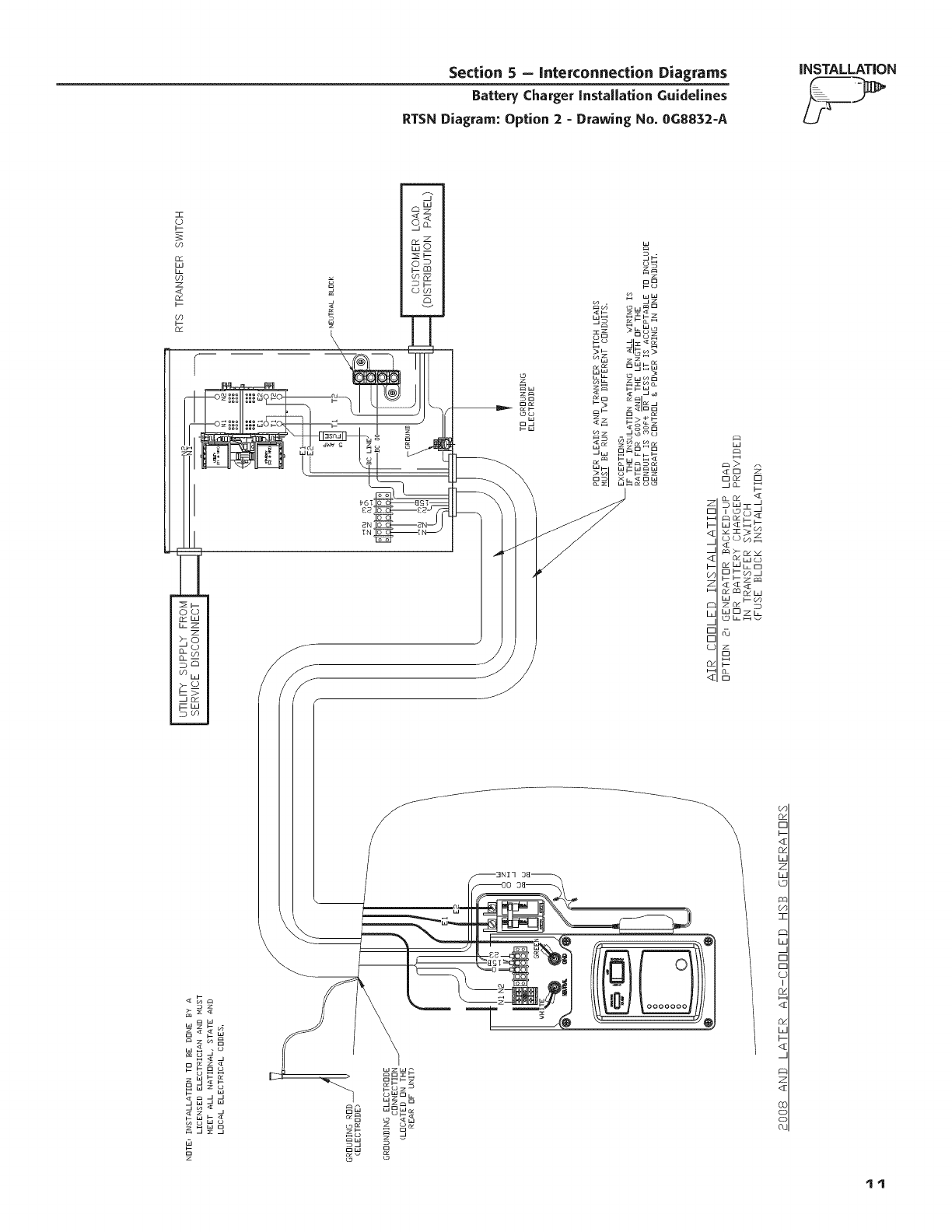
Section 5 - Interconnection Diagrams
Battery Charger installation Guidelines
RTSN Diagram: Option 2 - Drawing No. 0G8832-A
iNSTALLATION
8
o_ o
_WC3
Wb_C3
F--ZC a
b--_
d5
z
El
wzw_
_Sz_
oWo L
wOw_
_w
ow
o
o_
r-
I-
<:z
o_
L
z
L
c
O:
]Z
b
£
[-
LC
I
O_
Od
L
i--
<_
z
<z
OC
CL
tt
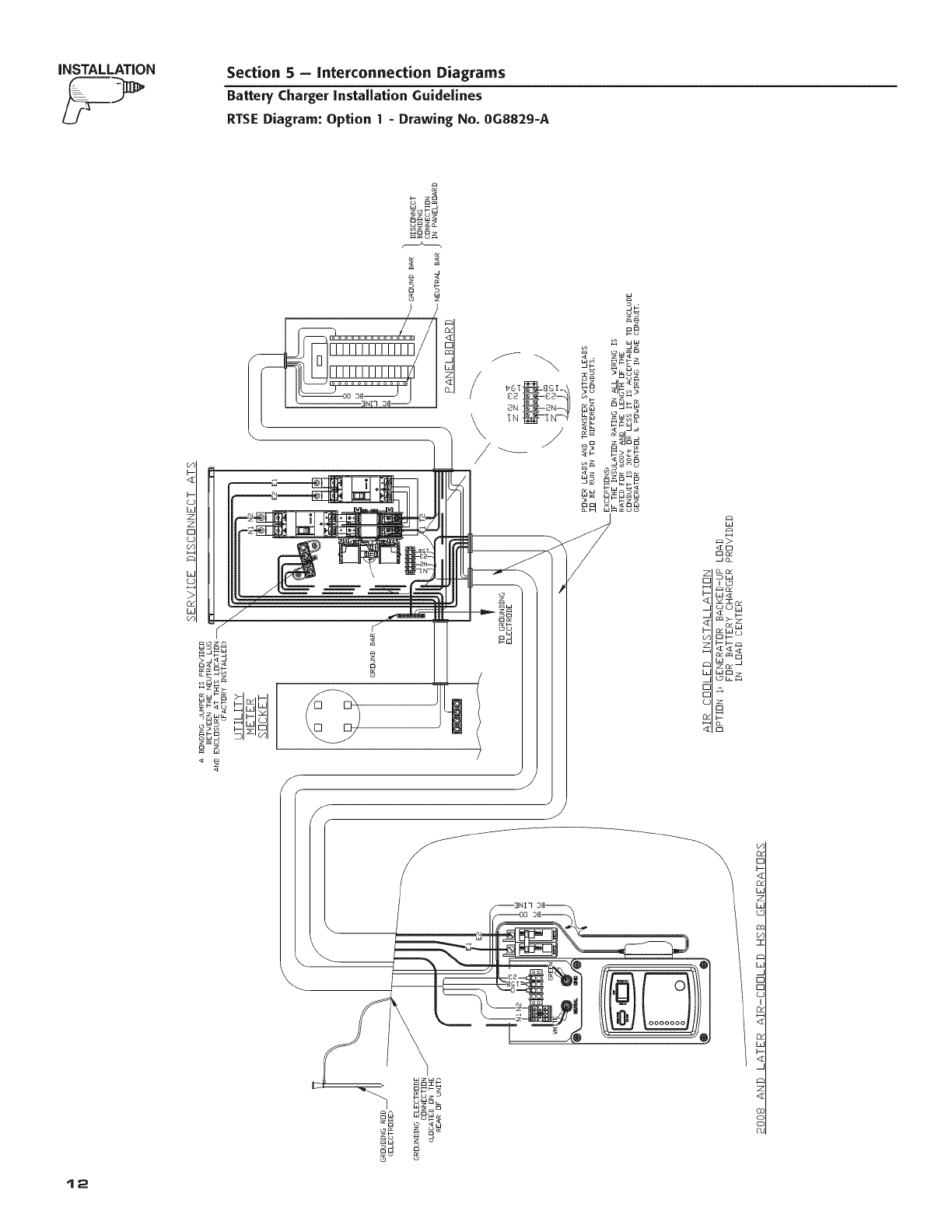
INSTALLATION Section 5 - Interconnection Diagrams
Battery Charger installation Guidelines
RTSE Diagram: Option 1- Drawing No. 0G8829-A
h
_- z_
o om
w _
Y
_o
o_
_W
c_w_
Ell--
Zl--I --
WC::I
_o__z
_g
12
Section 5 - Interconnection Diagrams
Battery Charger installation Guidelines
RTSE Diagram: Option 2 - Drawing No. 0G8829-A
iNSTALLATiON
b
_2
zo
w _
o
J
8
€:q
D_
jo_
_w
I £3
w_
DI--
_-- I--
WD
OL
n
_g
_z
wo
LD
(4J
_w
z_
<_
8
13
iNSTALLATiON Section 5 - Interconnection Diagrams
Battery Charger installation Guidelines
GenReady Diagram -Drawing No. 0G4744-C
x.
o_ w_
wo
z z _
Ow_O
_w_
z_O_
o w _
_oWw
--D o
_w
_ L_d
\
z
04
0
<[
04
LJ
Z
LJ
LD
w
z
LU
Z
LJ
L
Z
,q]
£L
Z
r--
i--
I--
QC
L
Z
Z
r--
QC
Lg
Z
I--
<_
0¢
(D
>
oo
co
<[z
co I
D--
_w
z>-
03;
LoW
0dW
O
_W
DZ
Wz_
Z_ W
_zS_
_ D
WH_
D_Z_
z_
D_
_wZ_
_ W
_w_W
_Z _
_W_
_W_
z_WD
D
Z
i'
W!
t4
Section 5 - Interconnection Diagrams
Battery CEarger instaUation Guidelines
GenReady Diagram - Drawing No. 0G4744-C
iNSTALLATiON
Od
0
<[
_d
W
Z
W
U
W
Z
G
Z
W
L
Z
<I
O_
z
E
QI
L
z
z
r-
L5
z
<_
<[
>
oo
co
d
Wz_
sS _z_B
zW_
0 0_
s_ S_d
_z
_W _
_W s3_
@
o
z
w
%
W

Section 6-Notes
Battery Charger instaUationGuidelines
t6

Section 6 -- Notes
Battery ChargerinstaUation Guidelines
t7