CARRIER Package Units(both Units Combined) Manual L0811829
WEATHERMASTER 48ZG L0811829
User Manual: CARRIER CARRIER Package Units(both units combined) Manual CARRIER Package Units(both units combined) Owner's Manual, CARRIER Package Units(both units combined) installation guides
Open the PDF directly: View PDF ![]() .
.
Page Count: 66
WEATHERMASTER ®
48ZG,ZN030-105
48ZT, ZW, Z6,Z8075-105
Single Package Gas Heating and Electric Cooling Units
with Direct Spark Ignition and COMFORTLINK TM Controls
Installation Instructions
CONTENTS
Page
GENERAL ........................................ 1
SAFETY CONSIDERATIONS ..................... 1,2
INSTALLATION ................................ 2-59
Jobsite Survey ................................... 2
Unit Placement ................................... 2
Roof Mount ...................................... 2
Slab Mount ....................................... 2
Curb Casketing .................................. 2
Field-Fabricated Ductwork ....................... 2
Rigging .......................................... 2
Condensate Drain Connections ................. 23
Install Outdoor Hoods
(48ZG,ZN,Z6,Z8 Units) ......................... 33
• UNIT SIZES 030-050
• UNIT SIZES 055-105
Install Economizer Hoods (48ZT, ZW Units) ...... 35
• INSTALL SMALL HOODS
• INSTALL LARGE HOODS
Field Wire Routing .............................. 36
• UNIT SIZES 030-050
• UNIT SIZES 055-105
Field Electrical Connections .................... 36
• POWER WIRING
Air Pressure Tubing ............................. 51
• INLET GUIDE VANES
• VARIABLE FRQUENCY DRIVE
• MODULATING POWER EXHAUST
• RETURN/EXHAUST POWER EXHAUST
Supply-Fan Shipping Brackets .................. 53
• UNIT SIZES 030-050
• UNIT SIZES 055-070
• UNIT SIZES 075-105
Return/Exhaust Fan Shipping Brackets
(48Z6,Z8 Units) ................................ 53
Remove TXV Shipping Blocks ................... 54
Compressor Mounting .......................... 55
Gas Piping ...................................... 55
Optional Staged Gas Control .................... 55
Installing Flue/Inlet Hoods ...................... 56
Supply Air Thermistors
(Staged Gas Units Only) ...................... 56
Install Unit Accessories ......................... 59
CONTROLS INSTALLATION .................. 59-66
Constant Volume Units .......................... 59
• CONTROL WIRING
Variable Air Volume Units ....................... 59
Optional and Accessory Control Wiring ......... 60
Carrier Comfort Network ®(CCN) Interface ....... 60
Smoke Control Modes ........................... 61
GENERAL
This installation instruction contains basic unit installation
information, including installation of thermostats and remote
temperature sensors.
For additional information and service instructions, refer to
the Controls and Troubleshooting literature also enclosed in
this literature packet.
The 48ZT, ZW units are equipped with standard integral
economizer and high-capacity power exhaust.
The 48Z6,Z8 units are equipped with factory-installed
return!exhaust fans.
The staged gas control (SGC) option adds the capability to
control the rooftop unit's gas heating system to a specified sup-
ply air temperature set point for purposes of tempering a cool
mixed-air condition.
SAFETY CONSIDERATIONS
Installation and servicing of air-conditioning equipment can
be hazardous due to system pressure and electrical compo-
nents. Only trained and qualified service personnel should
install, repair, or service air-conditioning equipment.
Untrained personnel can perform basic maintenance func-
tions of cleaning coils and filters and replacing filters. All
other operations should be performed by trained service per-
sonnel. When working on air-conditioning equipment, observe
precautions in the literature, tags and labels attached to the unit,
and other safety precautions that may apply.
Follow all safety codes, including ANSI (American Nation-
al Standards Institute) Z223.1. Wear safety glasses and work
gloves. Use quenching cloth for unbrazing operations. Have
fire extinguisher available for all brazing operations.
Before performing service or maintenance operations on
unit, turn off main power switch to unit. Electrical shock
could cause personal iniury.
Do not try to light any appliance. Do not touch any electri-
cal switch; do not use any phone in your building. Ilmnedi-
ately call your gas supplier from a neighbor's phone.
Follow the gas supplier's instructions. If you cannot reach
your gas supplier, call the fire department.
Improper installation, adjustment, alteration, service, or
maintenance can cause injury or property damage. Refer to
this manual. For assistance or additional information, con-
sult a qualified installer, service agency, or the gas supplier.
Manufacturer reserves the right to discontinue, or change at any time, specifications or designs without notice and without incurring obligations.
Catalog No. 04-53480044-O1 Printed in U.S.A. Form 48Z-7SI Pg 1 6-08 Replaces: 48Z-4SI
Disconnect gas piping from units when leak testing at pres-
sures greater than 0.5 psig. Pressures greater than 0.5 psig
will cause gas valve damage resulting in a hazardous
condition. If gas valve is subjected to pressure greater than
0.5 psig, it must be replaced. When pressure testing field-
supplied gas piping at pressures of 0.5 psig or less, the unit
connected to such piping must be isolated by manually
closing the gas valve.
INSTALLATION
Jobsite Survey EComplete the following checks before
installation.
1. Consult local building codes and the NEC (National
Electrical Code) (ANSI!NFPA [American National Stan-
dards Institute/National Fire Protection Association] 70)
for special installation requirements.
2. Determine unit location (from project plans) or select unit
location.
3. Check for possible overhead obstructions which may in-
terfere with unit lifting or rigging.
Do not lift unit with forklift truck. Move unit with over-
head rigging only.
Curb Gasketing
SIZE 030-050 UNITS -- After ductwork has been connected
to the roof curb, attach adhesive-backed gasketmg on all end
rails, cross rails, and duct rails. Be sure all joints and corners of
gasket are square and flush to prevent possible water leaks.
Follow all applicable building codes.
SIZE 055-105 UNITS -- After ductwork has been connected
to the roof curb, apply gasket material (1/:-in. thick x ll/:-in.
wide neoprene) where indicated.
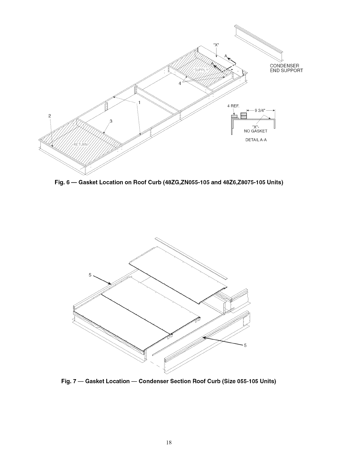
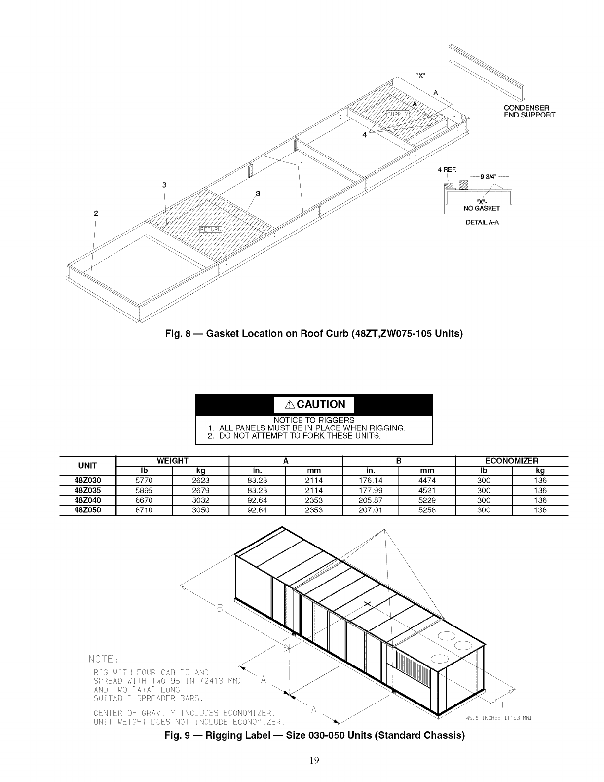
Single-Thickness Gasketing (See Fig 6-8 for Item Num-
bersl -- Apply gasketing in the following places:
1. Along both side rails (1) -- 2 places, full length
2. Along return air end rail (2) -- 1 place
3. Around return air internal duct flange (3) -- 1 or 2 places
4. Around supply air internal duct flanges (4) -- 3 places
Double-Thickness Gasketing (See Fig 6 and 8 and Detail
A-A! -- Locate a line 93/4-in. from the supply air end of the
accessory curb. Apply a double-thickness of gasket material
along with line per detail A-A.
NOTE: Do not apply gasket material along the outside edge of
the curb (area "X"). This pan area of the curb extends out
beneath the end of the unit's air handler section; applying gas-
ket here develops a potential water trap area on top of the curb.
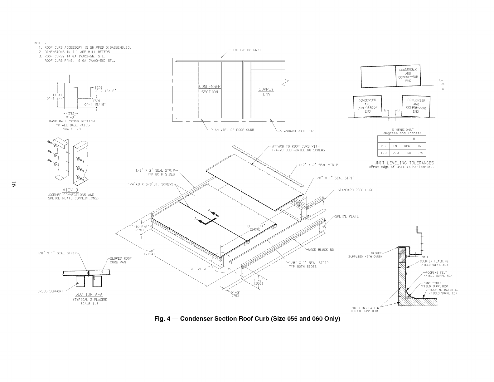
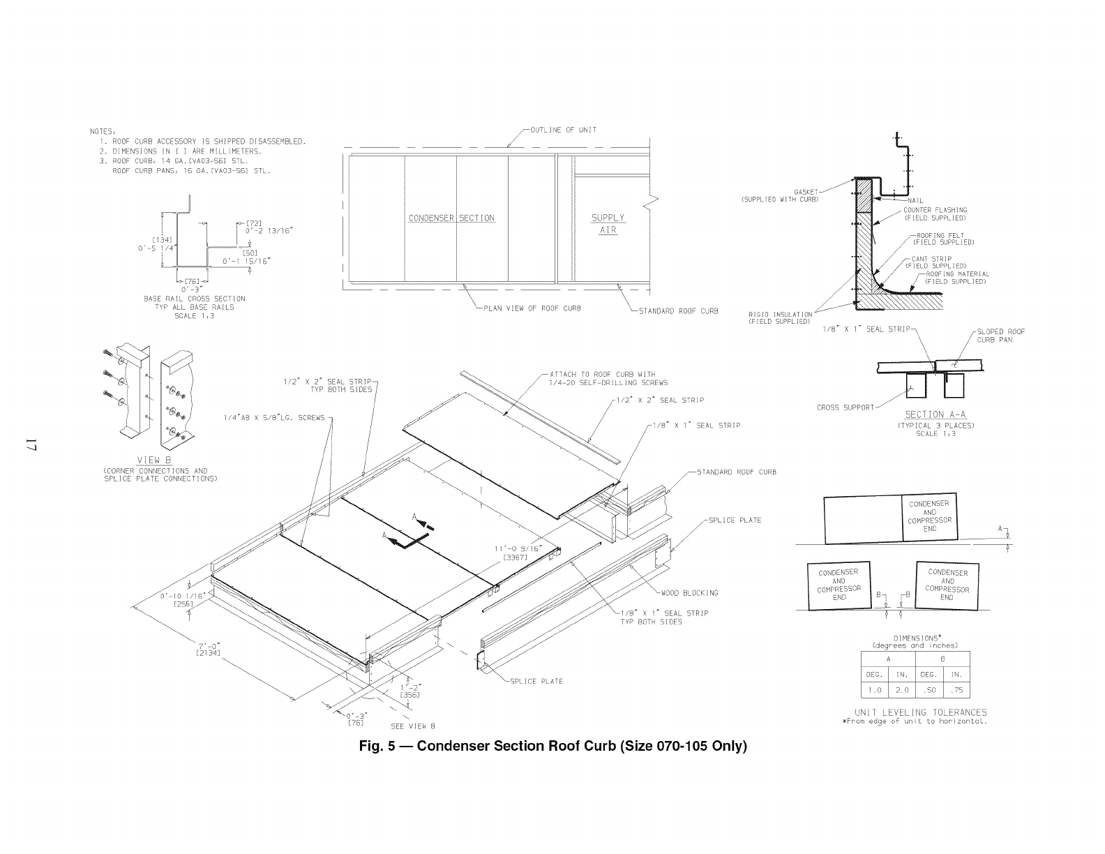
Condenser Section Roof Curb (See Fig. 7) -- Apply single-
thickness gasket along both side rails (5).
Field-Fabricated Ductwork
Unit Placement EInspect unit for transportation dam-
age. File claim with transportation agency.
Provide clearance around and above unit for airflow, safety,
and service access. Do not restrict top (area above condenser
fans) in any way. Allow at least 6 ft on all sides for rated perfor-
mance, code compliance, and service.
Check unit dimensional drawings for unit arrangement and
lnmimum performance and service clearances.
Do not install unit in an indoor location. Do not locate air in-
lets near exhaust vents or other sources of contaminated air.
On units equipped with power exhaust option, high velocity
air is exhausted out the hood. Unit should be positioned with at
least 10 ft clearance between the exhaust hood and any obstruc-
tion. Although unit is weatherproof, guard against water from
higher level runoff and overhangs.
Level by using unit frame as a reference. Physical data is
shown in Tables 1A-6.
Roof Mount _Check building codes for weight distribu-
tion requirements. Unit weight is shown in Tables 1A-1C and
2. Unit may be mounted on class A, B, or C roofing material.
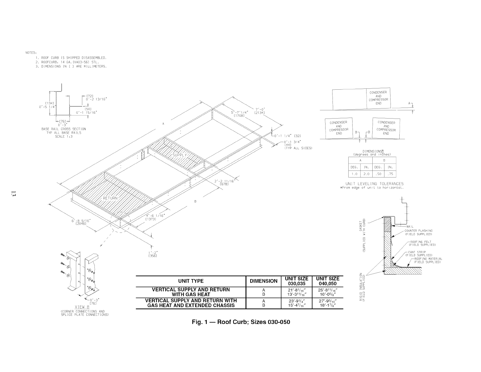
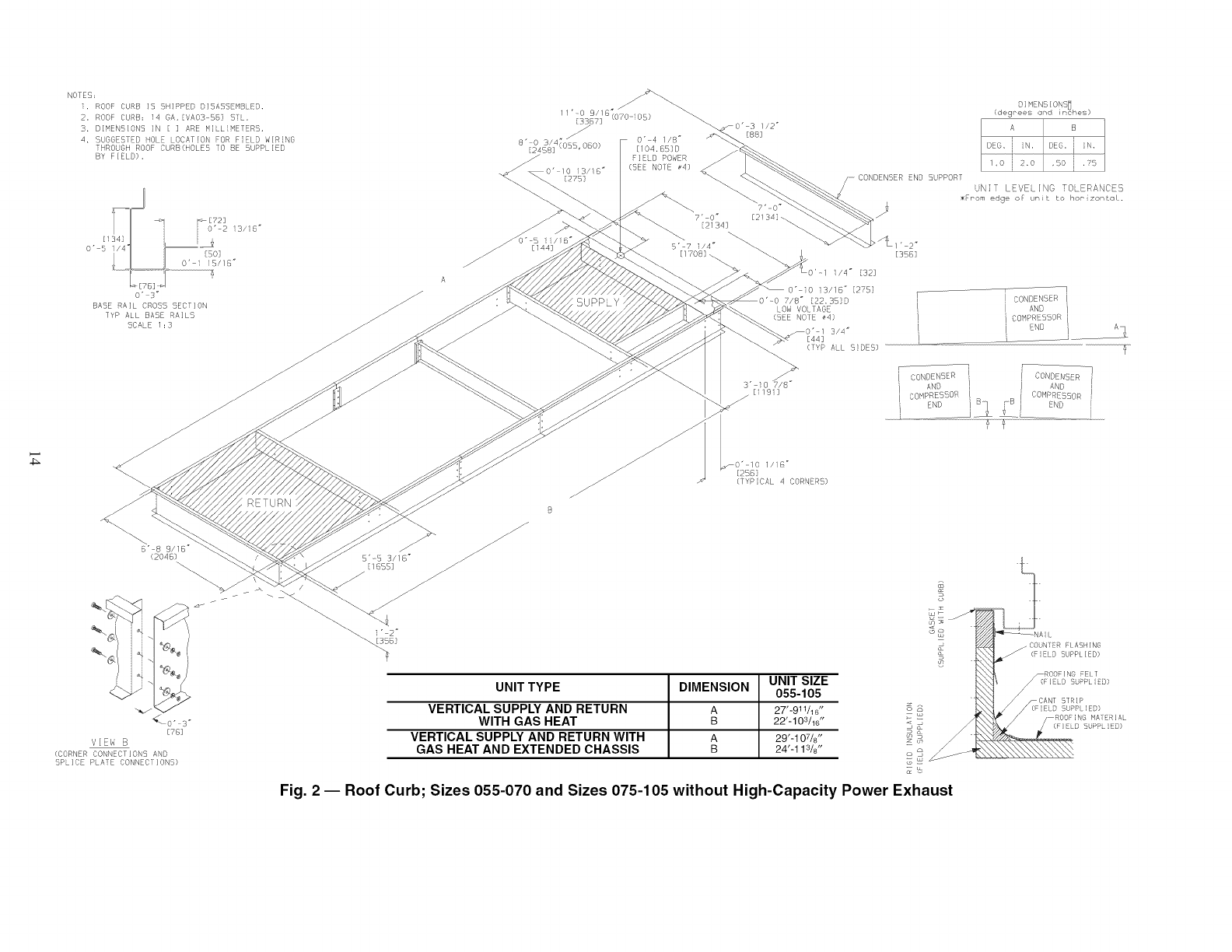
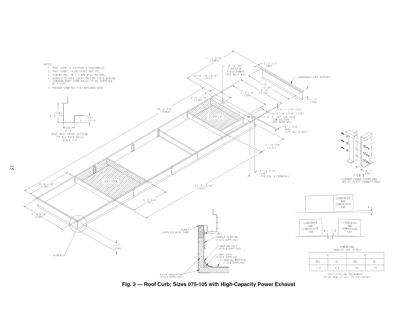
ROOF CURB -- Assemble and install roof curb as described
in instructions shipped with the accessory. Accessory roof curb
and information required to field fabricate a roof curb is shown
in Fig. 1-5. Install insulation, cant strips, roofing and counter
flashing as required. For unit condensate dram to function
properly, curb must be level or within tolerances shown m
Fig. 1-5.
STEEL BEAMS -- If roof curb is not used, support unit with
steel beams along its entire length and then support steel as re-
quired. As a minimum, unit must be supported across its width
at each lifting lug location.
Slab Mount _Provide a level concrete slab that extends
beyond unit cabinet at least 6 inches. Make a slab 8 in. thick
with 4 in. above grade. Use gravel apron m front of condenser
coil air inlet to prevent grass and foliage from obstructing
airflow. Ensure that slab is of sufficient height to allow for con-
densate trap of 4 in. on sizes 030-070 or 7 m. on sizes 075-105.
For vertical supply and return units, tools or parts could
drop into ductwork and cause an injury. Install a 90-degree
turn in the supply and return ductwork between the unit
and the conditioned space. If a 90-degree elbow cannot be
installed, then a grille of sufficient strength and density
should be installed to prevent objects from falling into the
conditioned space. Failure to follow these instructions
could result in personal injury or property damage due to
falling objects.
The 48ZG, ZN, ZT, ZW, Z6,Z8 units are designed for vertical
supply/return only. Field-fabricated ductwork must be attached
to the roof curb, on to the support steel, prior to the final rigging
and installation of the unit. Supply and return duct dhnensions
are shown in Fig. 1-3.
To attach ductwork to roof curb, insert duct approximately 10
to 11 m. up into roof curb. Connect ductwork to 14-gage roof
curb material with sheet metal screws driven from inside the duct.
Secure all ducts to the building structure, using flexible duct
connectors between roof curbs and ducts as required. Ducts
passing through an unconditioned space must be insulated and
covered with a vapor barrier. Outlet grilles must not lie directly
below unit discharge. The return duct must have a 90-degree
elbow before opening into the building space if the unit is
equipped with power exhaust.
Design supply duct strong enough to handle expected static
pressures.
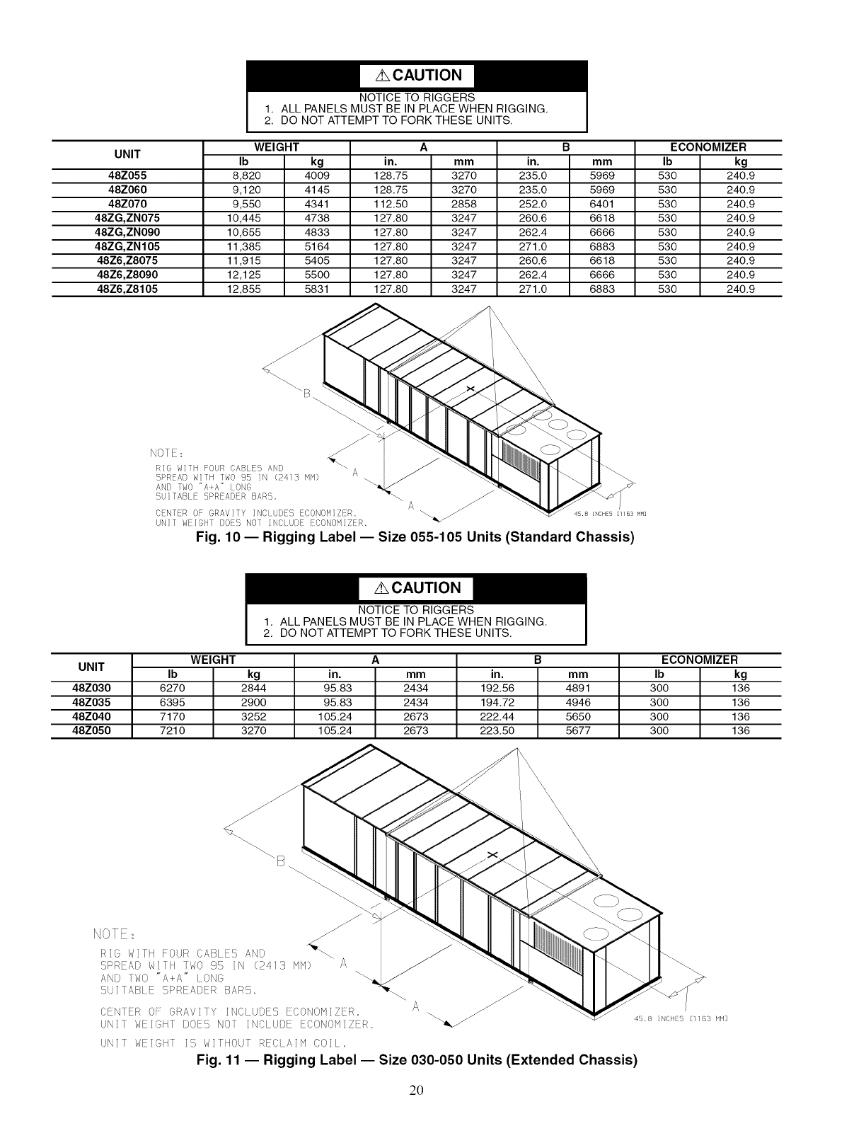
Rigging _Do not drop unit; keep upright. Use spreader
bars over unit to prevent sling or cable damage. Sheets of ply-
wood placed along the condenser coils will provide additional
protection. All lifting lugs MUST be used when lifting unit.
Level by using unit frame as a reference. See Fig. 9-13 for m-
formation. Unit and accessory weights are shown in Tables 1A-
1C and 2. Weight distribution and center of gravity can be
found in Fig. 14.
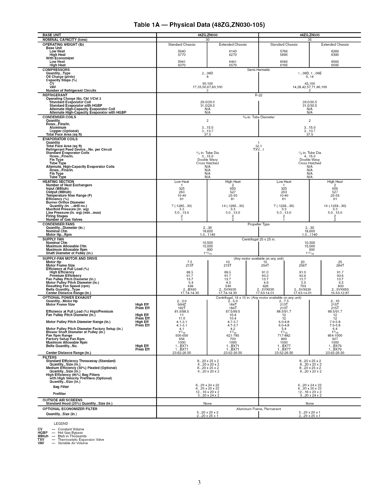
Table 1A -- Physical Data (48ZG,ZN030-105)
BASE UNIT
NOMINAL CAPACITY (tons)
OPERATING WEIGHT (Ib)
Base Unit
Low Heat
High Heat
With Economizer
Low Heat
High Heat
COMPRESSORS
Quantity...Type
Oil Charge (pints)
Capacity Steps (%)
CV
VAV
Number of Refriqerant Circuits
REFRIGERANT
Operating Charge (Ib), Ckt 1/Ckt 2
Standard Evaporator Coil
Standard Evaporator with HGBP
Alternate High-Capacity Evaporator Coil
Alternate Hi_lh-Capacity Evaporator with HGBP
CONDENSER COILS
Quantity
Rows...Fins/in.
Aluminum
Copper (Optional)
Total Face Area (soI ft)
EVAPORATOR COILS
Quantity
Total Face Area (sq ft)
Refrigerant Feed Device...No. per Circuit
Standard Evaporator Coils
Rows...Fins/in.
Fin Type
Tube Type
Alternate, High-Capacity Evaporator Coils
Rows...Fins/in.
Fin Type
Tube Type
HEATING SECTION
Number of Heat Exchangers
Input (MBtuh)
Output (MBtuh)
Temperature Rise Range (F)
Efficiency (%)
Burner Orifice Diameter
Quantity (in....drill no.)
Manifold Pressure (in. wg)
Line Pressure (in. wg) (min...max)
Firing Stages
Number of Gas Valves
CONDENSER FANS
Quantity...Diameter (in.)
Nominal Cfm
Motor Hp...Rpm
SUPPLY FAN
Nominal Cfm
Maximum Allowable Cfm
Maximum Allowable Rpm
Shaft Diameter at Pulley (in.)
SUPPLY-FAN MOTOR AND DRIVE
Motor Hp
Motor Frame Size
Efficiencyat Full Load (%)
High Efficiency
Premium Efficiency
Fan Pulley Pitch Diameter (in.)
Motor Pulley Pitch Diameter (in.)
Resulting Fan Speed (rpm)
Belts Quantity...Type
Center Distance Range (in.)
OPTIONAL POWER EXHAUST
Quantity...Motor Hp
Motor Frame Size
Efficiency at Full Load (%) High/Premium
Fan Pulley Pitch Diameter (in.)
Motor Pulley Pitch Diameter Range (in.)
Motor Pulley Pitch Diameter Factory Setup (in.)
Blower Shaft Diameter at Pulley (in.)
Fan Rpm Range
Factory Setup Fan Rpm
Maximum Allowable Rpm
Belts Quantity...No.
Center Distance Range (in.)
FILTERS
Standard Efficiency Throwaway (Standard)
Quantity...Size (in.)
Medium Efficiency (30%) Pleated (Optional)
Quantity...Size (in.)
High Efficiency (90%) Bag Filters
with High Velocity Prefilters (Optional)
Quantity...Size (in.)
Bag Filter
High Elf
Prem Elf
High Elf
Prem Elf
High Elf
Prem Elf
High Elf
Prem Elf
48ZG,ZN030 48ZG,ZN035
30 35
Standard Chassis Extended Chassis Standard Chassis Extended Chassis
5640 6140 5766 6266
5770 6270 5895 6395
5941 6441 6066 6566
6070 6570 6195 6695
Semi-Hermetic
2...06D I 1 ...06D, 1 ...06E
8 I 8,14
50,100 43,100
17,33,50,67,83,100 14,28,42,57,71,86,100
2 2
R-22
29,0/29.0 I 29.0/30.5
31.0/29.0 31.0/30.5
N/A N/A
N/A N/A
s/s-in. Tube Diameter
3...15.0 3...15.0
3...13.7 3...13.7
37.5 37.5
1
32.1
TXV...1
Low Heat
1
325
263
10-40
81
7 (.1285...30)
3.3
5.0...13.0
2
1
7.5
213T
88.5
91.7
13.7
3.4
438
2...BX60
17.74-14.30
2...3.0
56HZ
182T
81.0/88.5
11
11.0
4.1-3.1
4.1-3.1
4.1
17/16
500-656
656
1000
1...BX71
1...BX71
23.62-26.50
1/2 in. Tube Dia
3...15.0
Double Wavy
Cross Hatched
N/A
N/A
N/A
N/A
1/2 in. Tube Dia
4...15.0
Double Wavy
Cross Hatched
N/A
N/A
N/A
N/A
2_.30 2_.30
18,600 18,600
1.0...1140 1.0...1140
10,500 10,500
15,000 15,000
900 900
High Heat Low Heat
2 1
650 325
527 263
25-55 10-40
81 81
14 (.1285...30) 7 (. 1258...30)
3.3 3.3
5.0...13.0 5.0...13.0
2 2
2 1
Propeller Type
I
Centrifugal 25 x 25 in.
I
(Any motor available on any unit)
10 15
215T 254T
89.5 81.0
81.7 83.0
13.7 13.7
4.3 4.9
548 626
2...5VX630 2...5VX630
17.74-14.30 17.63-14.01
Centrifugal, 18 x 15 in. (Any motor available on any unit)
8_.20 x 25 x 2
8...20 x 20 x 2
8_.20 x 25 x 2
8...20 x 20 x 2
2...5.0
184T
184T
87.5/89.5
10.4
10.4
4.7-3.7
4.7-3.7
4.2
17/16
621-785
703
1000
1...BX71
1...BX71
23.62-26.50
2...7.5
213T
213T
88.5/81.7
12
12
6.0-4.8
6.0-4.8
5.4
1_16
717-882
800
1000
1...BX77
1...BX77
23.62-26.50
6...20 x 24 x 22
6_.20 x 20 x 22
12...16 x 20 x 2
3...20 x 24 x 2
20
256T
91.0
83.6
13.7
5.5
703
2...5VX630
17.63-14.01
8-.20 x 25 x 2
8...20 x 20 x 2
8...20 x 25 x 2
8...20 x 20 x 2
Prefilter
OUTSIDE AIR SCREENS
Standard Hood (25%) Quantity...Size (in.) None None
OPTIONAL ECONOMIZER FILTER Aluminurn Frame, Perrnanent
Ouantity...Size (in.) 2...205"20Xx2520Xx2 I 2...205"20Xx2520Xx11
LEGEND
CV -- Constant Volume
HGBP -- Hot Gas Bypass
MBtuh -- Btuh in Thousands
TXV -- Thermostatic Expansion Valve
VAV -- Variable Air Volume
6...20 x 24 x 22
6...20 x 20 x 22
12...16 x 20 x 2
3...20 x 24 x 2
High Heat
2
650
527
25-55
81
14 (.1258...30)
3.3
5.0...13.0
2
2
25
284T
91.7
93.6
13.7
6.5
830
2...5VX650
16.63-12.87
2...10
215T
215T
89.5/91.7
12
12
7.0-5.8
7.0-5.8
6.4
17/16
854-1000
927
1000
1...BX79
1...BX79
23.62-26.50
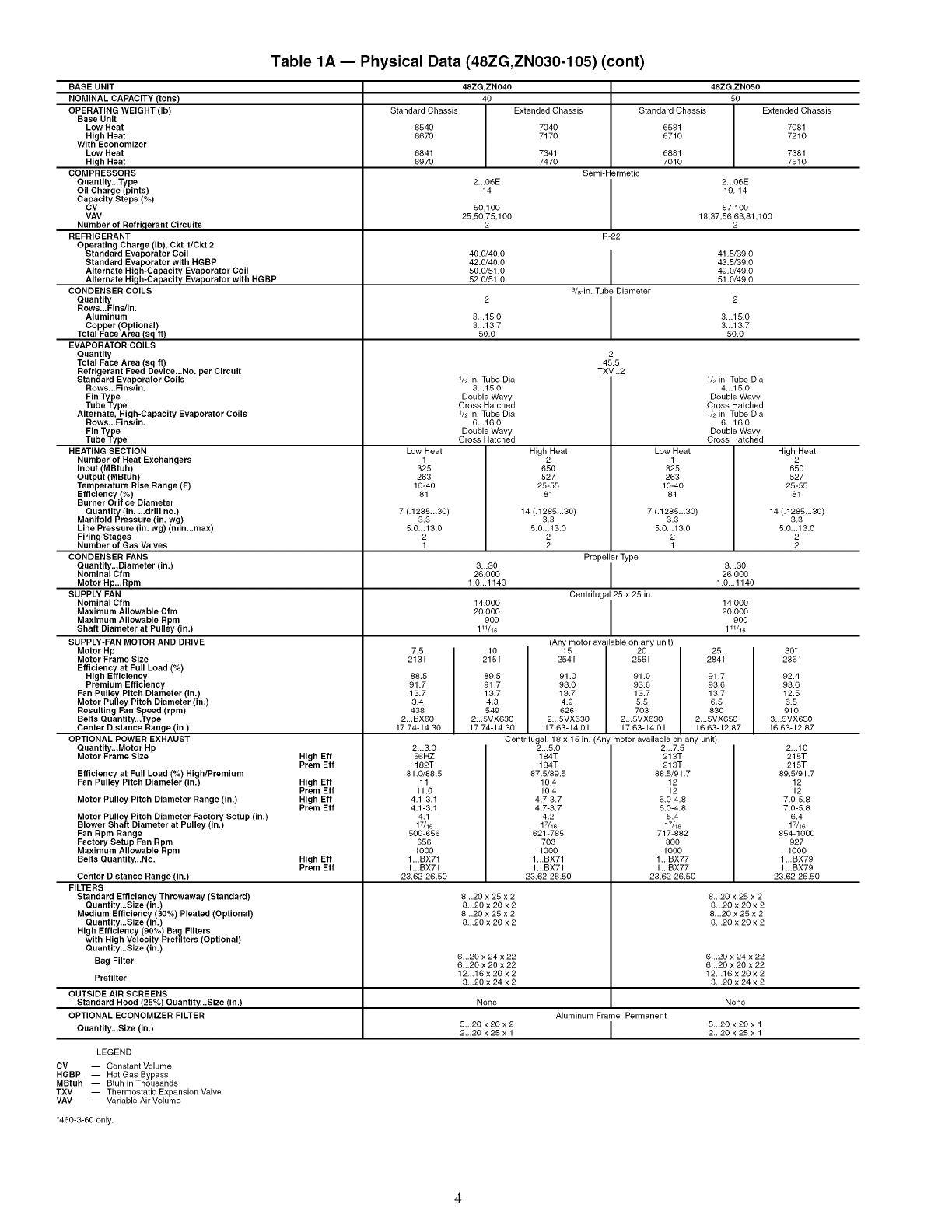
Table 1A- Physical Data (48ZG,ZN030-105) (cont)
BASE UNIT
NOMINAL CAPACITY (tons)
OPERATING WEIGHT (Ib)
Base Unit
Low Heat
High Heat
With Economizer
Low Heat
High Heat
COMPRESSORS
Quantity...Type
Oil Charge (pints)
Capacity Steps (%)
CV
VAV
Number of Refriclerant Circuits
REFRIGERANT
Operating Charge (Ib), Ckt 1/Ckt 2
Standard Evaporator Coil
Standard Evaporator with HGBP
Alternate High-Capacity Evaporator Coil
Alternate Hi_lh-Capacity Evaporator with HGBP
CONDENSER COILS
Quantity
Rows...Fins/in.
Aluminum
Copper (Optional)
Total Face Area/sq ft)
EVAPORATOR COILS
Quantity
Total Face Area (sq ft)
Refrigerant Feed Device...No. per Circuit
Standard Evaporator Coils
Rows...Fins/in.
Fin Type
Tube Type
Alternate, High-Capacity Evaporator Coils
Rows...Fins/in.
Fin Type
Tube Type
HEATING SECTION
Number of Heat Exchangers
Input (MBtuh)
Output (MBtuh)
Temperature Rise Range (F)
Efficiency (%)
Burner Orifice Diameter
Quantity (in....drill no.)
Manifold Pressure (in. wg)
Line Pressure (in. wg) (min...max)
Firing Stages
Number of Gas Valves
CONDENSER FANS
Quantity...Diameter (in.)
Nominal Cfm
Motor Hp...Rpm
SUPPLY FAN
Nominal Cfm
Maximum Allowable Cfm
Maximum Allowable Rpm
Shaft Diameter at Pulley (in.)
SUPPLY-FAN MOTOR AND DRIVE
Motor Hp
Motor Frame Size
Efficiencyat Full Load (%)
High Efficiency
Premium Efficiency
Fan Pulley Pitch Diameter (in.)
Motor Pulley Pitch Diameter (in.)
Resulting Fan Speed (rpm)
Belts Quantity...Type
Center Distance Range (in.)
OPTIONAL POWER EXHAUST
Quantity...Motor Hp
Motor Frame Size
Efficiency at Full Load (%) High/Premium
Fan Pulley Pitch Diameter (in.)
Motor Pulley Pitch Diameter Range (in.)
Motor Pulley Pitch Diameter Factory Setup (in.)
Blower Shaft Diameter at Pulley (in.)
Fan Rpm Range
Factory Setup Fan Rpm
Maximum Allowable Rpm
Belts Quantity...No.
Center Distance Range (in.)
FILTERS
Standard Efficiency Throwaway (Standard)
Quantity...Size (in.)
Medium Efficiency (30%) Pleated (Optional)
Quantity...Size (in.)
High Efficiency (90%) Bag Filters
with High Velocity Prefilters (Optional)
Quantity...Size (in.)
Bag Filter
High Elf
Prem Elf
High Elf
Prem Elf
High Elf
Prem Elf
High Elf
Prem Elf
48ZG,ZN040 48ZG,ZN050
40 50
Standard Chassis Extended Chassis Standard Chassis Extended Chassis
8540 7040 8581 7081
8870 7170 8710 7210
8841 7341 8881 7381
8970 7470 7010 7510
Semi-Hermetic
2...06E 2...06E
14 19, 14
50,100 57,100
25,50,75,100 18,37,58,63,81,100
2 2
R-22
40.0/40.0 I 41.5/39.0
42.0/40.0 I 43.5/39.0
50.0/51,0 49,0/49.0
52.0/51,0 51,0/49,0
s/8-in. Tube Diameter
3...15.0 3...15.0
3,..13.7 3,..13.7
50,0 50.0
Low Heat
1
325
283
10-40
81
7 (.1285...30)
3.3
5,0,,.13.0
2
1
7.5
213T
88.5
91.7
13.7
3.4
438
2...BX60
17.74-14.30
2...3.0
56HZ
182T
81.0/88.5
11
11.0
4.1-3.1
4.1-3.1
4.1
17/16
500-656
658
1000
1...BX71
1...BX71
23.82-28.50
1/2 in. Tube Dia
3...15.0
Double Wavy
Cross Hatched
1/2 in. Tube Dia
8...16.0
Double Wavy
Cross Hatched
2
45.5
TXV...2
Low Heat
1
325
283
10-40
81
7 (.1285...30)
3.3
5.0.,.13,0
2
1
V2 in. Tube Dia
4...15.0
Double Wavy
Cross Hatched
V2 in. Tube Dia
8...16.0
Double Wavy
Cross Hatched
3...30 3-.30
26,000 26,000
1.0.,.1140 1.0..,1140
14,000 14,000
20,000 20,000
900 900
1W16 111/16
10
215T
89.5
91.7
13.7
4.3
549
2...5VX630
17.74-14.30
High Heat
2
850
527
25-55
81
14 (.1285.,.30)
3.3
5.0...13.0
2
2
Propeller Type
I
Centrifugal 25 x 25 in.
I
(Any motor available on any unit)
15 20
254T 256T
91.0 91.0
93.0 93.6
13.7 13.7
4.9 5,5
626 703
2.,.5VX630 2.-5VX630
17.63-14.01 17.63-14.01
8...20 x 25 x 2
8...20 x 20 x 2
8...20 x 25 x 2
8...20 x 20 x 2
6...20 x 24 x 22
6...20 x 20 x 22
12...16 x 20 x 2
3...20 x 24 x 2
25
284T
91.7
93.6
13.7
6.5
83O
2...5VX650
16.83-12.87
Centrifugal, 18 x 15 in. (Any motor available on any unit)
2...5.0
184T
184T
87.5/89.5
10.4
10.4
4.7-3.7
4.7-3.7
4,2
17/16
621-785
703
1000
1,..BX71
1,..BX71
23.62-26.50
2...7.5
213T
213T
88.5/91.7
12
12
6.0-4.8
6.0-4.8
5.4
17/16
717-882
800
1000
1...BX77
1...BX77
23.82-28.50
8...20 x 25 x 2
8...20 x 20 x 2
8...20 x 25 x 2
8...20 x 20 x 2
Prefilter
OUTSIDE AIR SCREENS
Standard Hood (25%) Quantity...Size (in.) None None
OPTIONAL ECONOMIZER FILTER Aluminum Frame, Permanent
Quantity...Size (in.) 5...20 x 20 x 2 I 5...20 x 20 x 12.,,20 x 25 x 1 2..,20 x 25 x 1
LEGEND
CV -- Constant Volume
HGBP -- Hot Gas Bypass
MBtuh -- Btuh in Thousands
TXV -- Thermostatic Expansion Valve
VAV -- Variable Air Volume
6.-20 x 24 x 22
6...20 x 20 x 22
12...16 x 20 x 2
3...20 x 24 x 2
High Heat
2
650
527
25-55
81
14 (,1285..,30)
3.3
5.0...13.0
2
2
30*
286T
92.4
93.6
12.5
8.5
910
3...5VX630
16.63-12.87
2...10
215T
215T
89.5/91.7
12
12
7.0-5.8
7.0-5.8
8.4
1_16
854-1000
927
1000
1...BX79
1...BX79
23.62-28.50
*460-3-60 only.
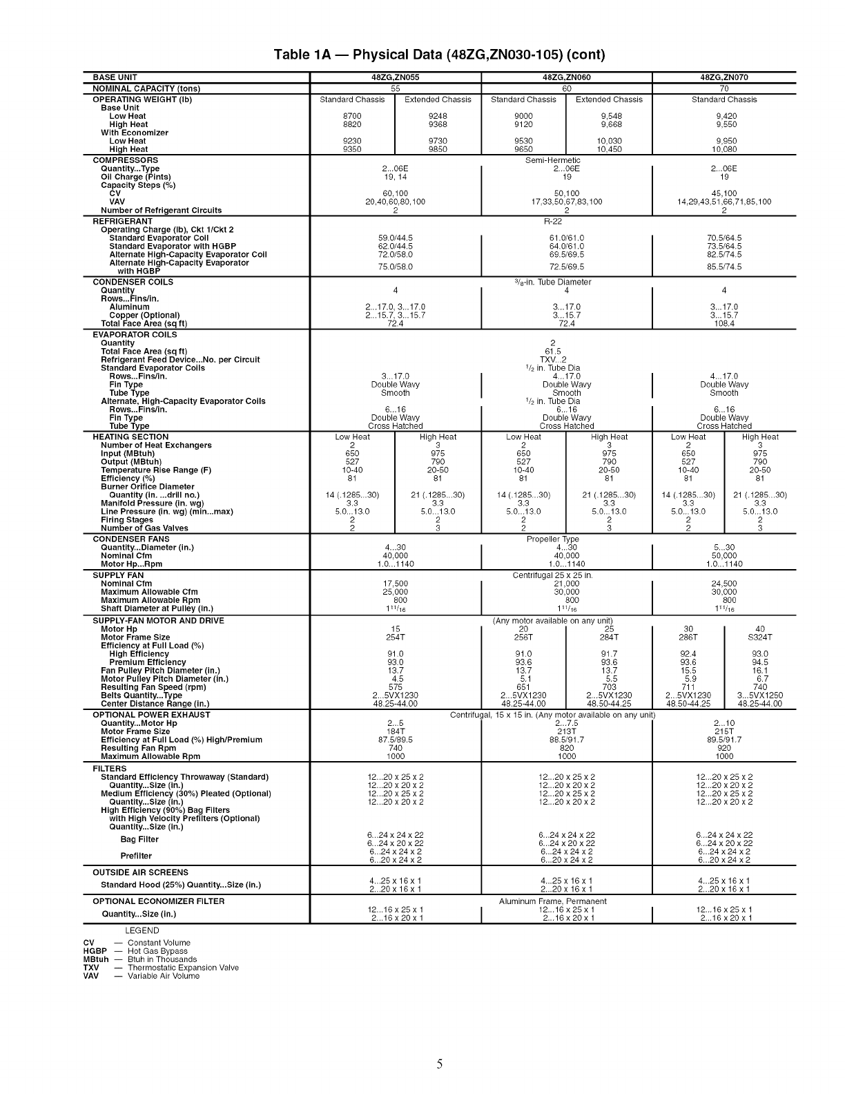
Table 1A- Physical Data (48ZG,ZN030-105) (cont)
48ZG,ZN055 48ZG,ZN060 48ZG,ZN070
55 60 70
Standard Chassis Extended Chassis Standard Chassis Extended Chassis Standard Chassis
8700 9248 9000 9,648 9,420
8820 9368 9120 9,668 9,550
9230 9730 9530 10,030 9,950
9350 9850 9650 10450 10,080
Semi-Hermetic
2...06E 2...06E I 2...06E
19, 14 19 I 19
60,100 50,100 45,100
20,40,60,80,100 17,33,50,67,83,100 14,29,43,51,66,71,85,100
2 2 2
R-22
59.0/44.5 61.0/61.0 I 70.5/64.5
62.0/44.5 64.0/61.0 I 73.5/64.5
72.0/58.0 69.5/69.5 82.5/74.5
75.0/58.0 72.5/69.5 85.5/74.5
3&-in. Tube Diameter
4 4 I 4
2...17.0, 3...17.0 3...17.0 I 3...17.0
2...15.7, 3...15.7 3...15.7 3...15.7
72.4 72.4 108.4
BASE UNIT
NOMINAL CAPACITY (tons)
OPERATING WEIGHT (Ib)
Base Unit
Low Heat
High Heat
With Economizer
Low Heat
High Heat
COMPRESSORS
Quantity...Type
Oil Charge (Pints)
Capacity Steps (%)
CV
VAV
Number of Refrigerant Circuits
REFRIGERANT
Operating Charge (Ib), Ckt l/Ckt 2
Standard Evaporator Coil
Standard Evaporator with HGBP
Alternate High-Capacity Evaporator Coil
Alternate High-Capacity Evaporator
with HGBP
CONDENSER COILS
Quantity
Rows._Fins/in.
Aluminum
Copper (Optional)
Total Face Area (sq ft)
EVAPORATOR COILS
Quantity
Total Face Area (sq ft)
Refrigerant Feed Device...No. per Circuit
Standard Evaporator Coils
Rows...Fins/in.
Fin Type
Tube Type
Alternate, High-Capacity Evaporator Coils
Rows...Fins/in.
Fin Type
Tube Type
HEATING SECTION
Number of Heat Exchangers
Input (MBtuh)
Output (MBtuh)
Temperature Rise Range (F)
Efficiency (%)
Burner Orifice Diameter
Quantity (in....drill no.)
Manifold Pressure (in. wg)
Line Pressure (in. wg) (min...max)
Firing Stages
Number of Gas Valves
CONDENSER FANS
Quantity...Diameter (in.)
Nominal Cfm
Motor Hp...Rpm
SUPPLY FAN
Nominal Cfm
Maximum Allowable Cfm
Maximum Allowable Rpm
Shaft Diameter at Pulley (in.)
SUPPLY-FAN MOTOR AND DRIVE
Motor Hp
Motor Frame Size
Efficiency at Full Load (%)
High Efficiency
Premium Efficiency
Fan Pulley Pitch Diameter (in.)
Motor Pulley Pitch Diameter (in.)
Resulting Fan Speed (rpm)
Belts Quantity...Type
Center Distance Range (in.)
OPTIONAL POWER EXHAUST
Quantity...Motor Hp
Motor Frame Size
Efficiency at Full Load (%) High/Premium
Resulting Fan Rpm
Maximum Allowable Rpm
FILTERS
Standard Efficiency Throwaway (Standard)
Quantity...Size (in.)
Medium Efficiency (30%) Pleated (Optional)
Quantity...Size (in.)
High Efficiency (90%) Bag Filters
with High Velocity Prefilters (Optional)
Quantity...Size (in.)
Bag Filter
3...17.0
Double Wavy
Smooth
6...16
Double Wavy
Cross Hatched
Low Heat
2
650
527
10-40
81
14 (.1285...30)
3.3
5.0...13.0
2
2
High Heat
3
975
79O
20-50
81
21 (.1285...30)
3.3
5.0...13.0
2
3
4...17.0
Double Wavy
Smooth
6...16
Double Wavy
Cross Hatched
Low Heat High Heat
2 3
650 975
627 790
10-40 20-50
81 81
14 (.1285...30) 21 (.1285...30)
3.3 3.3
5.0...13.0 5.0...13.0
2 2
2 3
4...30 5...30
40,000 50,000
1.0...1140 1.0...1140
17,500 24,500
25,000 30,000
800 800
111/16 111/16
15
254T
91.0
93.0
13.7
4.5
575
2...5VX1230
48.25-44.00
2_.5
184T
87.5/89.5
74O
1000
2
61.5
TXV...2
1/2 in. Tube Dia
4...17.0
Double Wavy
Smooth
1/2 in. Tube Dia
6...16
Double Wavy
Cross Hatched
Low Heat High Heat
2 3
650 975
527 790
10-40 20-50
81 81
14 (.1285...30) 21 (.1285...30)
3.3 3.3
5.0...13.0 5.0...13.0
2 2
2 3
Propeller Type
I I
40,000
1.0..1140
Centrifugal 25 x 25 in.
21,000 I
30,000
800
111/16
(Any motor available on any unit)
20 25
256T 284T
91.0 91.7
93.6 93.6
13.7 13.7
5.1 5.5
651 703
2...5VX1230 2...5VX1230
48.25-44.00 48.50-44.25
Centrifugal, 15 x 15 in. (Any motor available on any unit)
2...7.5
213T
88.5/91.7
820
1000
12...20 x 25 x 2
12...20 x 20 x 2
12...20 x 25 x 2
12...20 x 20 x 2
6...24 x 24 x 22
6...24 x 20 x 22
6...24 x 24 x 2
6...20 x 24 x 2
12...20 x 25 x 2
12...20 x 20 x 2
12...20 x 25 x 2
12...20 x 20 x 2
6...24 x 24 x 22
6...24 x 20 x 22
6...24 x 24 x 2
6...20 x 24 x 2
3O 4O
286T S324T
92.4 93.0
93.6 94.5
15.5 16.1
5.9 6.7
711 740
2...5VX1230 3...5VX1250
48.50-44.25 48.25-44.00
2...10
215T
89.5/91.7
92O
1000
12...20 x 25 x 2
12...20 x 20 x 2
12...20 x 25 x 2
12...20 x 20 x 2
Prefilter
OUTSIDE AIR SCREENS
Standard Hood (25%) Ouantity...Size (in.) 4...25 x 16 x 1 4 25 x 16 x 1 4 .25 x 16 x 1
2...20 x 16x 1 2...20 x 16x 1 2...20 x 16 x 1
OPTIONAL ECONOMIZER FILTER Aluminum Frame Permanent
Ouantity...Size (in.) 12'"16 x 25 x 11 I 12...16 x 25 x 1 I 12""16 x 25 x 112...16 x 20 x 2...16 x 20 x 1 2,..16 x 20 x
LEGEND
CV i Constant Volume
HGBP -- Hot Gas Bypass
MBtuh -- Btuh in Thousands
TXV -- Thermostatic Expansion Valve
VAV -- Variable Air Volume
6...24 x 24 x 22
6...24 x 20 x 22
6...24 x 24 x 2
6...20 x 24 x 2
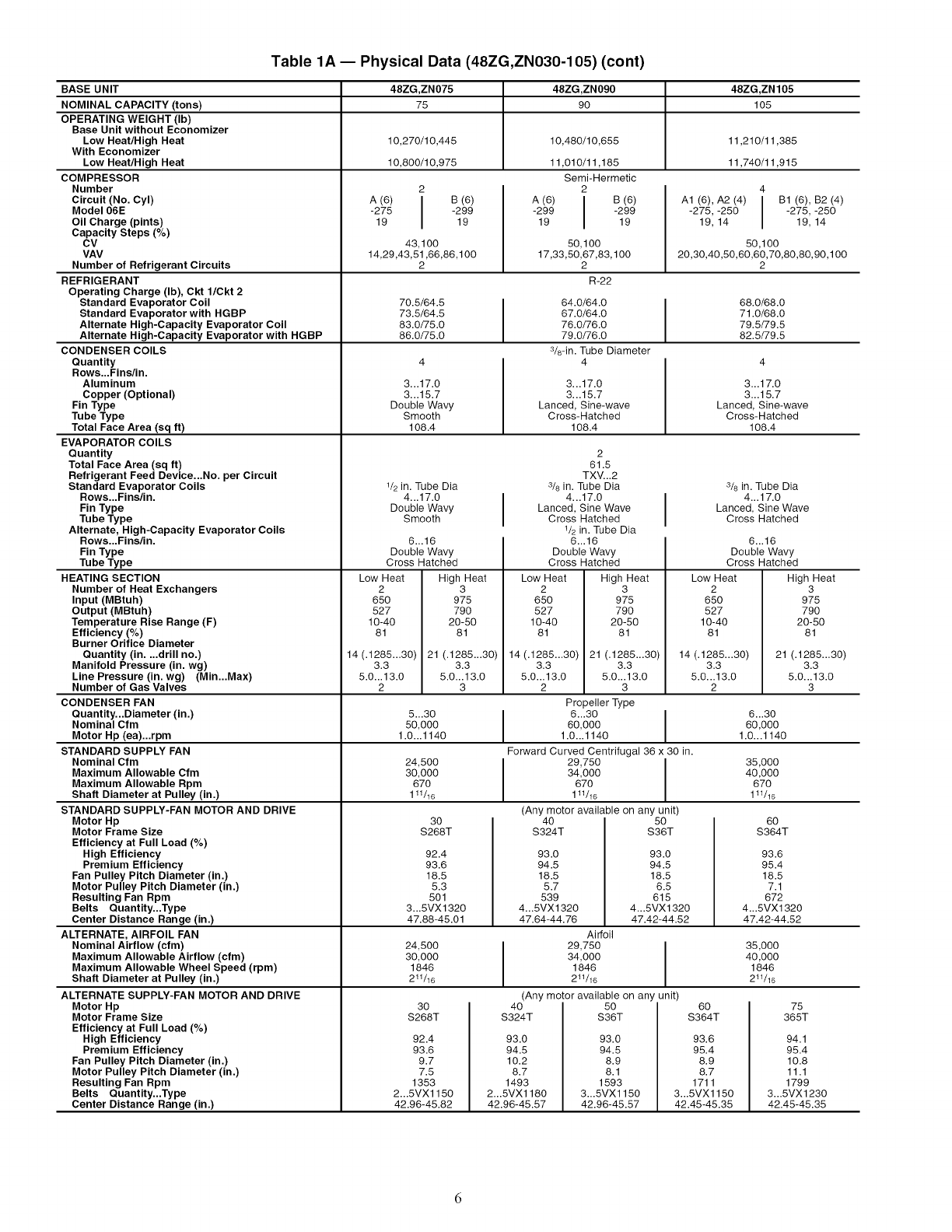
Table 1A- Physical Data (48ZG,ZN030-105) (cont)
BASE UNIT
NOMINAL CAPACITY (tons)
OPERATING WEIGHT (Ib)
Base Unit without Economizer
Low Heat/High Heat
With Economizer
Low Heat/High Heat
COMPRESSOR
Number
Circuit (No. Cyl)
Model 06E
Oil Charge (pints)
Capacity Steps (%)
CV
VAV
Number of Refrigerant Circuits
REFRIGERANT
Operating Charge (Ib), Ckt 1/Ckt 2
Standard Evaporator Coil
Standard Evaporator with HGBP
Alternate High-Capacity Evaporator Coil
Alternate High-Capacity Evaporator with HGBP
CONDENSER COILS
Quantity
Rows...Fins/in.
Aluminum
Copper (Optional)
Fin Type
Tube Type
Total Face Area (sq ft)
EVAPORATOR COILS
Quantity
Total Face Area (sq ft)
Refrigerant Feed Device...No. per Circuit
Standard Evaporator Coils
Rows...Fins/in.
Fin Type
Tube Type
Alternate, High-Capacity Evaporator Coils
Rows...Fins/in.
Fin Type
Tube Type
HEATING SECTION
Number of Heat Exchangers
Input (MBtuh)
Output (MBtuh)
Temperature Rise Range (F)
Efficiency (%)
Burner Orifice Diameter
Quantity (in....drill no.)
Manifold Pressure (in. wg)
Line Pressure (in. wg) (Min...Max)
48ZG,ZN075 48ZG,ZN090 48ZG,ZN105
75 90 105
10,270/10,445 10,480/10,655 11,210/11,385
10,800/10,975 11,010/11,185 11,740/11,915
Semi-Hermetic
22
A (6) IB (6)
-275 I -29919 19
43,100
14,29,43,51,66,86,100
2
70.5/64.5
73.5/64.5
83.0/75.0
86.0/75.0
3...17.0
3...15.7
Double Wavy
Smooth
108.4
1/2in. Tube Dia
4...17.0
Double Wavy
Smooth
6...16
Double Wavy
Cross Hatched
Low Heat
2
65O
527
10-40
81
14 (.1285...30)
3.3
5.0...13.0
2
High Heat
3
975
790
20-50
81
21 (.1285...30)
3.3
5.0...13.0
3
A (6) IB (6)
-299 I -29919 19
50,100
17,33,50,67,83,100
2
R-22
64.0/64.0
67.0/64.0
76.0/76.0
79.0/76.0
3&-in. Tube Diameter
4
3...17.0
3...15.7
Lanced, Sine-wave
Cross-Hatched
108.4
A1 (6), A2 (4) IB1 (6), B2 (4)
-275, -250 I -275, -250
19, 14 19, 14
50,100
20,30,40,50,60,60,70,80,80, 90,1 O0
2
68.0/68.0
71.0/68.0
79.5/79.5
82.5/79.5
2
61.5
TXV...2
3/s in. Tube Dia
4...17.0
Lanced, Sine Wave
Cross Hatched
1/2 in. Tube Dia
6...16
Double Wavy
Cross Hatched
Low Heat
2
65O
527
10-40
81
14 (.1285...30)
3.3
5.0...13.0
2
High Heat
3
975
790
20-50
81
21 (.1285...30)
3.3
5.0...13.0
3
3...17.0
3...15.7
Lanced, Sine-wave
Cross-Hatched
108.4
3/s in. Tube Dia
4...17.0
Lanced, Sine Wave
Cross Hatched
6...16
Double Wavy
Cross Hatched
Low Heat
2
650
527
10-40
81
14 (.1285...30)
3.3
5.0...13.0
2Number of Gas Valves
CONDENSER FAN
Quantity...Diameter (in.) 5...30 6...30
Nominal Cfm 50,000 60,000
Motor Hp (ea)...rpm 1.0...1140 1.0...1140
STANDARD SUPPLY FAN
Nominal Cfm 24,500 35,000
Maximum Allowable Cfm 30,000 40,000
670 670
111/16 111/16
30 60
$268T $364T
Propeller Type
I 630 I
60,000
1.0...1140
Forward Curved Centrifugal 36 x 30 in.
34,000
670
111/16
(Any motor available on any unit)
40 50
S324T S36T
93.0 93.0
94.5 94.5
18.5 18.5
5.7 6.5
539 615
4...5VXl 320 4...5VX1320
47.64-44.76 47.42-44.52
Airfoil
29,750
34,000
1846
211/16
(Any motor available on an unit)
92.4
93.6
18.5
5.3
501
3...5VX1320
47.88-45.01
24,500
30,000
1846
211/16
40
$324T
93.0
94.5
10.2
8.7
1493
2...5VX1180
42.96-45.57
50
S36T
93.0
94.5
8.9
8.1
1593
3...5VX1150
42.96-45.57
60
S364T
93.6
95.4
8.9
8.7
1711
3...5VX1150
42.45-45.35
30
$268T
92.4
93.6
9.7
7.5
1353
2...5VX1150
42.96-45.82
Maximum Allowable Rpm
Shaft Diameter at Pulley (in.)
STANDARD SUPPLY-FAN MOTOR AND DRIVE
Motor Hp
Motor Frame Size
Efficiency at Full Load (%)
High Efficiency
Premium Efficiency
Fan Pulley Pitch Diameter (in.)
Motor Pulley Pitch Diameter (in.)
Resulting Fan Rpm
Belts Quantity...Type
Center Distance Range (in.)
ALTERNATE, AIRFOIL FAN
Nominal Airflow (cfm)
Maximum Allowable Airflow (cfm)
Maximum Allowable Wheel Speed (rpm)
Shaft Diameter at Pulley (in.)
ALTERNATE SUPPLY-FAN MOTOR AND DRIVE
Motor Hp
Motor Frame Size
Efficiency at Full Load (%)
High Efficiency
Premium Efficiency
Fan Pulley Pitch Diameter (in.)
Motor Pulley Pitch Diameter (in.)
Resulting Fan Rpm
Belts Quantity...Type
Center Distance Range (in.)
93.6
95.4
18.5
7.1
672
4...5VX1320
47.42-44.52
35,000
40,000
1846
211/16
High Heat
3
975
790
20-50
81
21 (.1285...30)
3.3
5.0...13.0
3
94.1
95.4
10.8
11.1
1799
3...5VX1230
42.45-45.35
75
365T
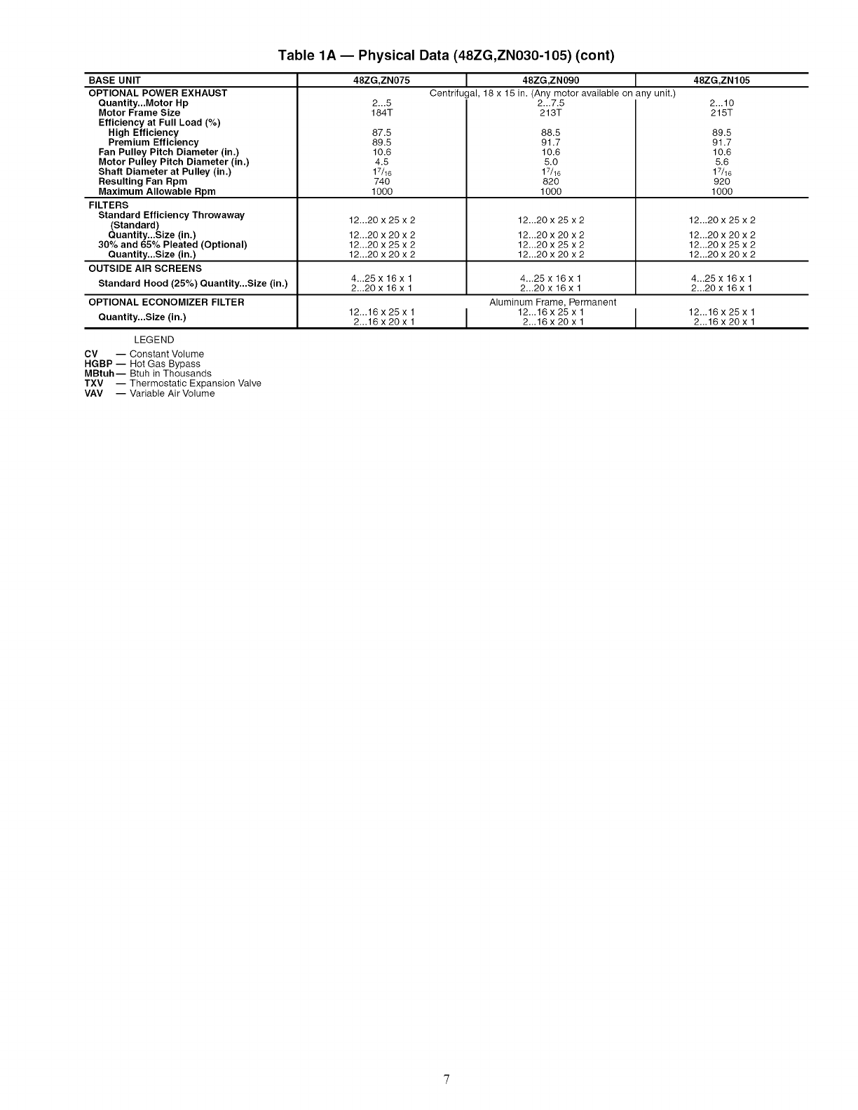
Table 1A- Physical Data (48ZG,ZN030-105) (cont)
BASE UNIT
OPTIONAL POWER EXHAUST
Quantity...Motor Hp
Motor Frame Size
Efficiency at Full Load (%)
High Efficiency
Premium Efficiency
Fan Pulley Pitch Diameter (in.)
Motor Pulley Pitch Diameter (in.)
Shaft Diameter at Pulley (in.)
Resulting Fan Rpm
Maximum Allowable Rpm
FILTERS
Standard Efficiency Throwaway
(Standard)
Quantity...Size (in.)
30% and 65% Pleated (Optional)
Quantity...Size (in.)
OUTSIDE AIR SCREENS
48ZG,ZN07S I48ZG,ZN0g0 I48ZG,ZN10S
Centrifugal, 18 x 15 in. (Any motor available on any unit.)
2...7.5
213T
2...5
184T
87.5
89.5
10.6
4.5
17/16
740
1000
88.5
91.7
10.6
5.0
17/16
820
1000
2...10
215T
89.5
91.7
10.6
5.6
17/16
920
1000
LEGEND
CV -- Constant Volume
HGBP -- Hot Gas Bypass
MBtuh-- Btuh in Thousands
TXV -- Thermostatic Expansion Valve
VAV -- Variable Air Volume
12...20 x 25 x 2 12...20 x 25 x 2 12...20 x 25 x 2
12...20 x 20 x 2 12...20 x 20 x 2 12...20 x 20 x 2
12...20 x 25 x 2 12...20 x 25 x 2 12...20 x 25 x 2
12...20 x 20 x 2 12...20 x 20 x 2 12...20 x 20 x 2
4...25 x 16 x 1 4...25 x 16x 1 4...25 x 16x 1
Standard Hood (25%) Quantity...Size (in.) 2...20 x 16 x 1 2...20 x 16 x 1 2...20 x 16 x 1
OPTIONAL ECONOMIZER FILTER Aluminum Frame, Permanent
Quantity...Size (in.) 12...16 x 25 x 1 12...16 x 25 x 1 I 12...16 x 25 x 12...16x20x1 2...16x20x1 2...16x20x1
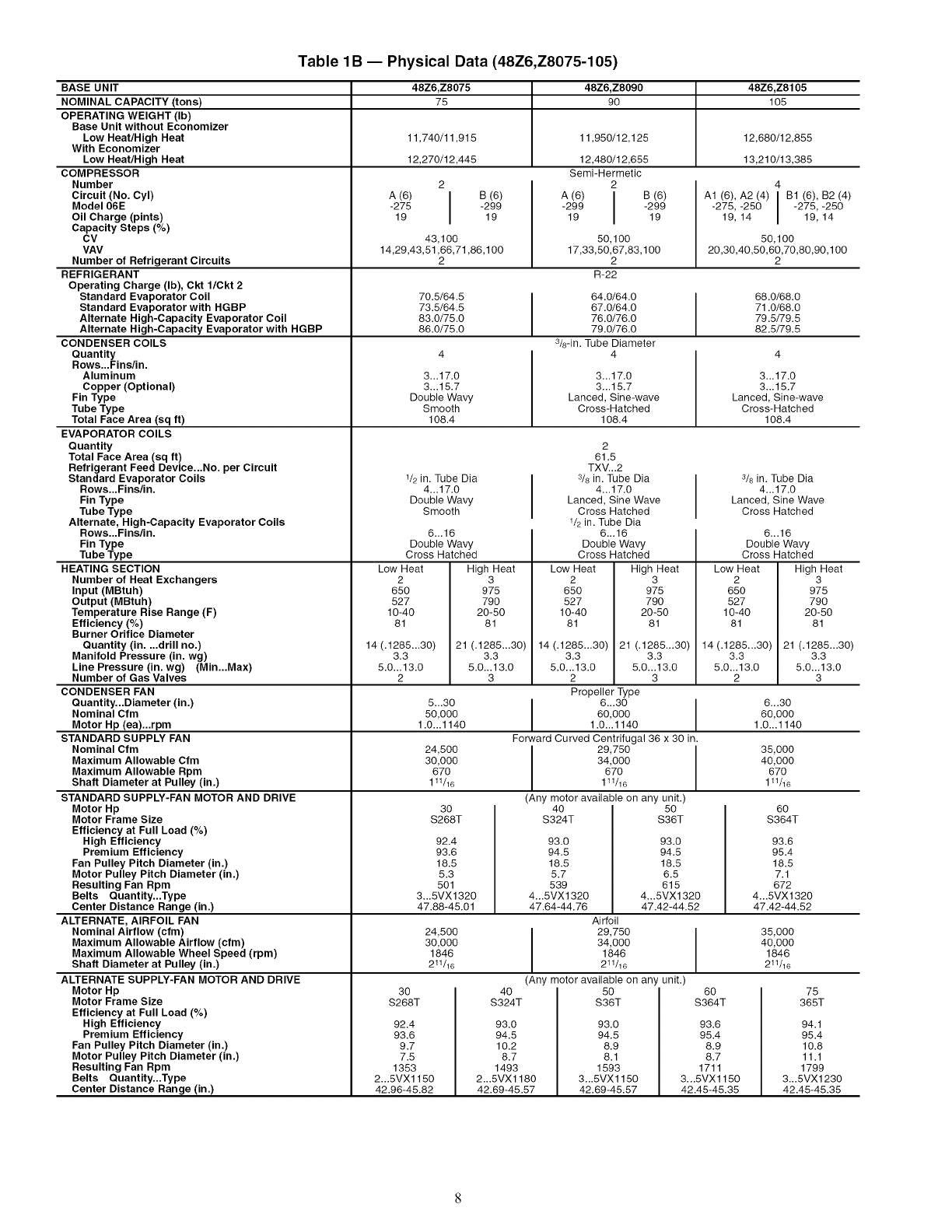
Table 1B -- Physical Data (48Z6,Z8075-105)
BASE UNIT
NOMINAL CAPACITY (tons)
OPERATING WEIGHT (Ib)
Base Unit without Economizer
Low Heat/High Heat
With Economizer
Low Heat/High Heat
COMPRESSOR
Number
Circuit (No. Cyl)
Model 06E
Oil Charge (pints)
Capacity Steps (%)
CV
VAV
Number of Refrigerant Circuits
REFRIGERANT
Operating Charge (Ib), Ckt 1/Ckt 2
Standard Evaporator Coil
Standard Evaporator with HGBP
Alternate High-Capacity Evaporator Coil
Alternate High-Capacity Evaporator with HGBP
CONDENSER COILS
Quantity
Rows...Fins/in.
Aluminum
Copper (Optional)
Fin Type
Tube Type
Total Face Area (sq ft)
EVAPORATOR COILS
Quantity
Total Face Area (sq ft)
Refrigerant Feed Device...No. per Circuit
Standard Evaporator Coils
Rows...Fins/in.
Fin Type
Tube Type
Alternate, High-Capacity Evaporator Coils
Rows...Fins/in.
Fin Type
Tube Type
HEATING SECTION
Number of Heat Exchangers
Input (MBtuh)
Output (MBtuh)
Temperature Rise Range (F)
Efficiency (%)
Burner Orifice Diameter
Quantity (in....drill no.)
Manifold Pressure (in. wg)
Line Pressure (in. wg) (Min...Max)
48Z6,Z8075 48Z6,Z8090 48Z6,Z8105
75 90 105
11,740/11,915 11,950/12,125 12,680/12,855
12,270/12,445 12,480/12,655 13,210/13,385
Semi-Hermetic
2
A (6) IB (6)
-299 I -29919 19
2
A (6) IB (6)
-275 I -29919 19
43,100
14,29,43,51,66,71,86,1 O0
2
50,100
17,33,50,67,83,100
2
R-22
4
A1 (6), A2 (4) IB1 (6), B2 (4)
-275, -250 I -275, -250
19, 14 19, 14
50,100
20,30,40,50,60,70,80,90,100
2
70.5/64.5 I 64.0/64.0 68.0/68.0
73.5/64.5 I 67.0/64.0 71.0/68.0
83.0/75.0 76.0/76.0 79.5/79.5
86.0/75.0 79.0/76.0 82.5/79.5
3/8-in. Tube Diameter
4 4 4
3...17.0
3...15.7
Double Wavy
Smooth
108.4
1/2 in. Tube Dia
4...17.0
Double Wavy
Smooth
6...16
Double Wavy
Cross Hatched
Low Heat
2
650
527
10-40
81
14 (.1285...30)
3.3
5.0...13.0
2
3...17.0
3...15.7
Lanced, Sine-wave
Cross-Hatched
108.4
2
61.5
TXV...2
,3/8in. Tube Dia
4...17.0
Lanced, Sine Wave
Cross Hatched
1/2in. Tube Dia
6...16
Double Wavy
Cross Hatched
Low Heat
2
650
527
10-40
81
High Heat
3
975
790
20-50
81
High Heat
3
975
790
20-50
81
21 (.1285...30)
3.3
5.0...13.0
3
3...17.0
3...15.7
Lanced, Sine-wave
Cross-Hatched
108.4
14 (.1285...30) 21 (.1285...30)
3.3 3.3
5.0...13.0 5.0...13.0
2 3
Propeller Type
I 6...3oI
60,000
1.0...1140
Forward Curved Centrifugal 36 x 30 in.
I 29,750
34,000
670
111/16
(Any motor available on any unit.)
3/8 in. Tube Dia
4...17.0
Lanced, Sine Wave
Cross Hatched
6...16
Double Wavy
Cross Hatched
Low Heat
2
650
527
10-40
81
14 (.1285...30)
3.3
5.0...13.0
2Number of Gas Valves
CONDENSER FAN
Quantity...Diameter (in.) 5...30 6...30
Nominal Cfm 50,000 60,000
Motor Hp (ea)...rpm 1.0...1140 1.0...1140
STANDARD SUPPLY FAN
Nominal Cfm 24,500 35,000
Maximum Allowable Cfm 30,000 40,000
Maximum Allowable Rpm 670 670
Shaft Diameter at Pulley (in.) 111/16 111/16
30 40 50 60
$268T $324T $36T $364T
STANDARD SUPPLY-FAN MOTOR AND DRIVE
Motor Hp
Motor Frame Size
Efficiency at Full Load (%)
High Efficiency
Premium Efficiency
Fan Pulley Pitch Diameter (in.)
Motor Pulley Pitch Diameter (in.)
Resulting Fan Rpm
Belts Quantity...Type
Center Distance Range (in.)
ALTERNATE, AIRFOIL FAN
Nominal Airflow (cfm)
Maximum Allowable Airflow (cfm)
Maximum Allowable Wheel Speed (rpm)
Shaft Diameter at Pulley (in.)
ALTERNATE SUPPLY-FAN MOTOR AND DRIVE 30
S268T
92.4
93.6
9.7
7.5
1353
2...5VX1150
42.96-45.82
40
$324T
93.0
94.5
18.5
5.7
539
4...5VX1320
47.64-44.76
93.0
94.5
18.5
6.5
615
4...5VX1320
47.42-44.52
Airfoil
29,750
34,000
1846
211/16
I
92.4
93.6
18.5
5.3
501
3...5VX1320
47.88-45.01
60
$364T
93.6
95.4
8.9
8.7
1711
3...5VX1150
42.45-45.35
24,500
30,000
1846
211/16
Motor Hp
Motor Frame Size
Efficiency at Full Load (%)
High Efficiency
Premium Efficiency
Fan Pulley Pitch Diameter (in.)
Motor Pulley Pitch Diameter (in.)
Resulting Fan Rpm
Belts Quantity...Type
Center Distance Range (in.)
(Any motor available on any unit.)
93.0
94.5
10.2
8.7
1493
2...5VX1180
42.69-45.57
50
$36T
93.0
94.5
8.9
8.1
1593
3...5VX1150
42.69-45.57
High Heat
3
975
790
20-50
81
21 (.1285...30)
3.3
5.0...13.0
3
93.6
95.4
18.5
7.1
672
4...5VX1320
47.42-44.52
35,000
40,000
1846
211/16
75
365T
94.1
95.4
10.8
11.1
1799
3...5VX1230
42.45-45.35
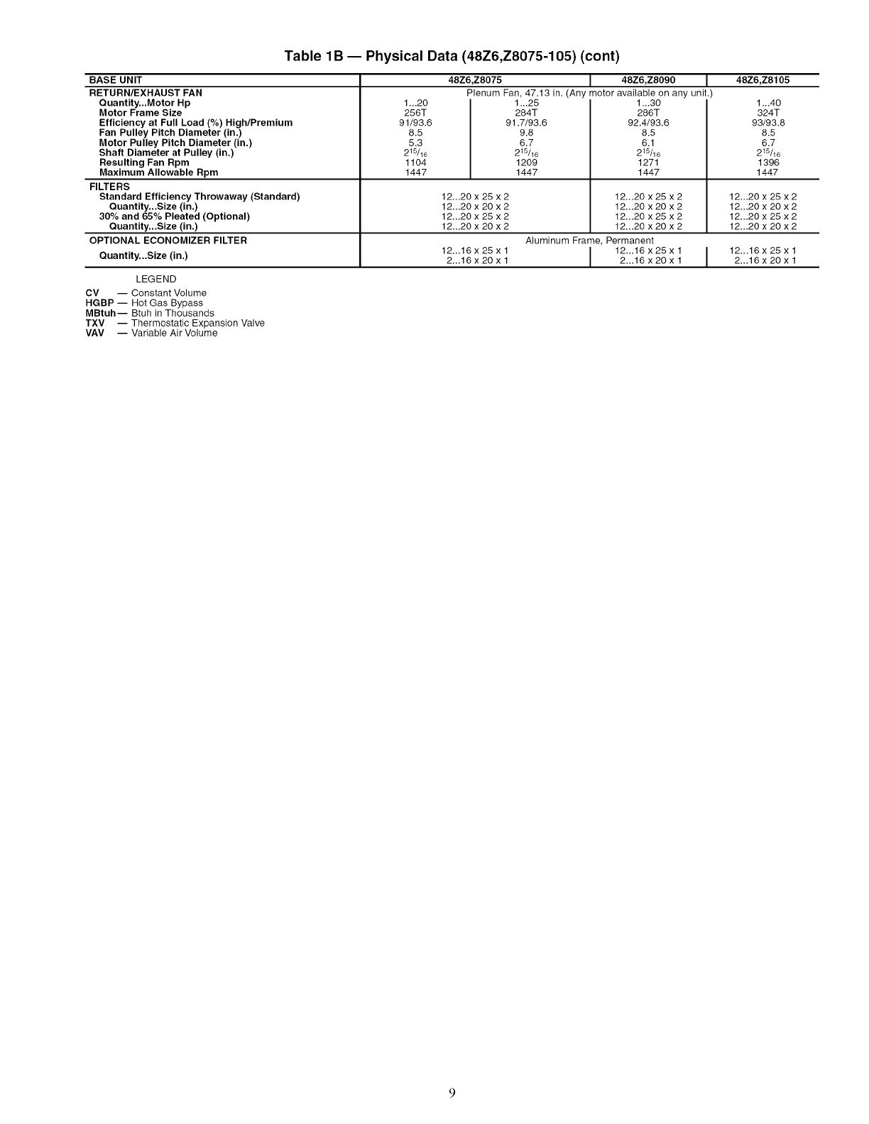
Table 1B -- Physical Data (48Z6,Z8075-105) (cont)
BASE UNIT
RETURN/EXHAUST FAN
Quantity...Motor Hp
Motor Frame Size
Efficiency at Full Load (%) High/Premium
Fan Pulley Pitch Diameter (in.)
Motor Pulley Pitch Diameter (in.)
Shaft Diameter at Pulley (in.)
Resulting Fan Rpm
Maximum Allowable Rpm
FILTERS
Standard Efficiency Throwaway (Standard)
Quantity...Size (in.)
30% and 65% Pleated (Optional)
Quantity...Size (in.)
OPTIONAL ECONOMIZER FILTER
1...20
256T
91/93.6
8.5
5.3
215/16
1104
1447
48Z6,ZS075 [48Z6,Z8090 1
Plenum Fan, 47.13 in. (Any motor available on any unit.)
1_.25
284T
91.7/93.6
9.8
6.7
215/16
1209
1447
1...30
286T
92.4/93.6
8.5
6.1
215/16
1271
1447
48Z6,Z8105
1...40
324T
93/93.8
8.5
6.7
215/16
1396
1447
LEGEND
CV -- Constant Volume
HGBP -- Hot Gas Bypass
MBtuh-- Btuh in Thousands
TXV -- Thermostatic Expansion Valve
VAV -- Variable Air Volume
12...20 x 25 x 2 12...20 x 25 x 2 12...20 x 25 x 2
12...20 x 20 x 2 12...20 x 20 x 2 12...20 x 20 x 2
12...20 x 25 x 2 12...20 x 25 x 2 12...20 x 25 x 2
12...20 x 20 x 2 12...20 x 20 x 2 12...20 x 20 x 2
Aluminum Frame, Permanent
Quantity...Size (in.) 12...16 x 25xl I 12...16 x 25 x l I 12...16 x 25xl
2...16 x 20 x 1 2...16 x 20 x 1 2...16 x 20 x 1
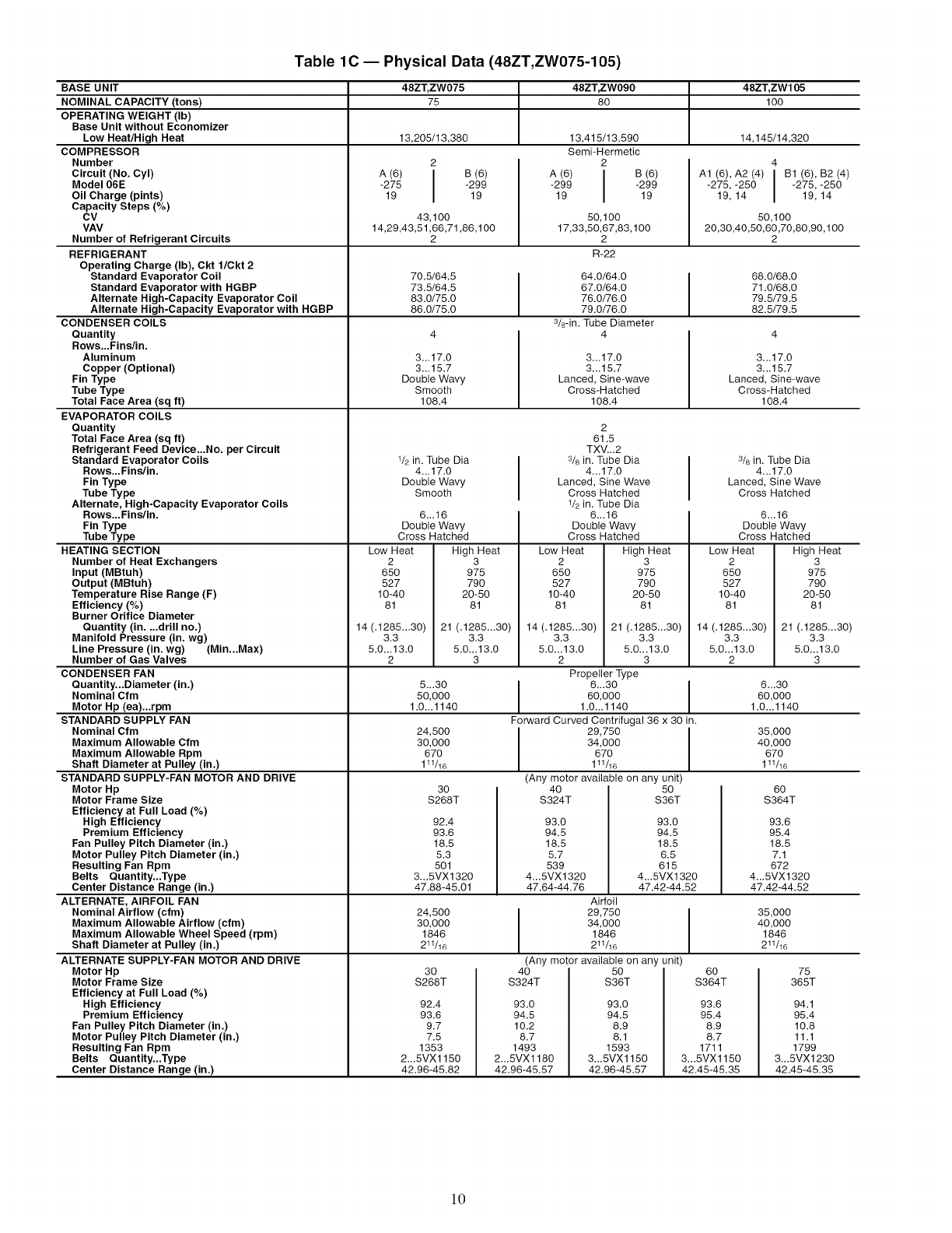
Table 1C -- Physical Data (48ZT,ZW075-105)
BASE UNIT
NOMINAL CAPACITY (tons)
OPERATING WEIGHT (Ib)
Base Unit without Economizer
Low Heat/High Heat
COMPRESSOR
Number
Circuit (No. Cyl)
Model 06E
Oil Charge (pints)
Capacity Steps (%)
CV
VAV
Number of Refrigerant Circuits
REFRIGERANT
Operating Charge (Ib), Ckt 1/Ckt 2
Standard Evaporator Coil
Standard Evaporator with HGBP
Alternate High-Capacity Evaporator Coil
Alternate High-Capacity Evaporator with HGBP
CONDENSER COILS
Quantity
Rows...Fins/in.
Aluminum
Copper (Optional)
Fin Type
Tube Type
Total Face Area (sq ft)
EVAPORATOR COILS
Quantity
Total Face Area (sq ft)
Refrigerant Feed Device...No. per Circuit
Standard Evaporator Coils
Rows...Fins/in.
Fin Type
Tube Type
Alternate, High-Capacity Evaporator Coils
Rows...Fins/in.
Fin Type
Tube Type
HEATING SECTION
Number of Heat Exchangers
Input (MBtuh)
Output (MBtuh)
Temperature Rise Range (F)
Efficiency (%)
Burner Orifice Diameter
Quantity (in....drill no.)
Manifold Pressure (in. wg) (Min...Max)
48ZT, ZW075 48ZT,ZW090 48ZT, ZW105
75 80 100
13,205/13,380 13,415/13,590 14,145/14,320
Semi-Hermetic
2
A (6) IB (6)
-299 I -29919 19
2
A (6) IB (6)
-275 I -29919 19
43,100
14,29,43,51,66,71,86,100
2
50,100
17,33,50,67,83,100
2
R-22
4
A1 (6), A2 (4) IB1 (6), B2 (4)
-275, -250 I -275, -250
19, 14 19, 14
50,100
20,30,40,50,60,70,80,90,100
2
70.5/64.5 64.0/64.0 68.0/68.0
73.5/64.5 67.0/64.0 71.0/68.0
83.0/75.0 76.0/76.0 79.5/79.5
86.0/75.0 79.0/76.0 82.5/79.5
3&-in. Tube Diameter
4 4 4
3...17.0
3...15.7
Double Wavy
Smooth
108.4
1/2 in. Tube Dia
4...17.0
Double Wavy
Smooth
6...16
Double Wavy
Cross Hatched
Low Heat
2
65O
527
10-40
81
14 (.1285...30)
3.3
5.0...13.0
2
3...17.0
3...15.7
Lanced, Sine-wave
Cross-Hatched
108.4
High Heat
3
975
790
20-50
81
21 (.1285...30)
3.3
5.0...13.0
3
2
61.5
TXV...2
3& in. Tube Dia
4...17.0
Lanced, Sine Wave
Cross Hatched
1/2in. Tube Dia
6...16
Double Wavy
Cross Hatched
Low Heat
2
650
527
10-40
81
High Heat
3
975
790
20-50
81
3...17.0
3...15.7
Lanced, Sine-wave
Cross-Hatched
108.4
3& in. Tube Dia
4...17.0
Lanced, Sine Wave
Cross Hatched
14 (.1285...30) 21 (.1285...30)
3.3 3.3
5.0...13.0 5.0...13.0
2 3
Propeller Type
I 630 I
60,000
1.0...1140
Forward Curved Centrifugal 36 x 30 in.
29,750
34,000
670
111/16
(Any motor available on any unit)
40 50
$324T $36T
93.0 93.0
94.5 94.5
18.5 18.5
5.7 6.5
539 615
4...5VX1320 4...5VX1320
47.64-44.76 47.42-44.52
Airfoil
6...16
Double Wavy
Cross Hatched
Low Heat High Heat
2 3
650 975
527 790
10-40 20-50
81 81
14 (.1285...30)
3.3
5.0...13.0
2
Line Pressure (in. wg)
Number of Gas Valves
CONDENSER FAN
Quantity...Diameter (in.) 5...30 6...30
Nominal Cfm 50,000 60,000
Motor Hp (ea)...rpm 1.0... 1140 1.0... 1140
STANDARD SUPPLY FAN
Nominal Cfm 24,500 35,000
Maximum Allowable Cfm 30,000 40,000
Maximum Allowable Rpm 670 670
Shaft Diameter at Pulley (in.) 111/16 111/16
30 60
$268T $364T
92.4
93.6
18.5
5.3
501
3...5VX1320
47.88-45.01
24,500
30,000
1846
211/16
29,750
34,000
1846
211/16
(Any motor available on any unit)
40
$324T 50
$36T
93.0
94.5
8.9
8.1
1593
3...5VX1150
42.96-45.57
60
$364T
93.6
95.4
8.9
8.7
1711
3...5VX1150
42.45-45.35
STANDARD SUPPLY-FAN MOTOR AND DRIVE
Motor Hp
Motor Frame Size
Efficiency at Full Load (%)
High Efficiency
Premium Efficiency
Fan Pulley Pitch Diameter (in.)
Motor Pulley Pitch Diameter (in.)
Resulting Fan Rpm
Belts Quantity...Type
Center Distance Range (in.)
ALTERNATE, AIRFOIL FAN
Nominal Airflow (cfm)
Maximum Allowable Airflow (cfm)
Maximum Allowable Wheel Speed (rpm)
Shaft Diameter at Pulley (in.)
ALTERNATE SUPPLY-FAN MOTOR AND DRIVE 30
$268T
21 (.1285...30)
3.3
5.0...13.0
3
92.4
93.6
9.7
7.5
1353
2...5VX1150
42.96-45.82
93.0
94.5
10.2
8.7
1493
2...5VX1180
42.96-45.57
Motor Hp
Motor Frame Size
Efficiency at Full Load (%)
High Efficiency
Premium Efficiency
Fan Pulley Pitch Diameter (in.)
Motor Pulley Pitch Diameter (in.)
Resulting Fan Rpm
Belts Quantity...Type
Center Distance Range (in.)
93.6
95.4
18.5
7.1
672
4...5VX1320
47.42-44.52
35,000
40,000
1846
211/16
75
365T
94.1
95.4
10.8
11.1
1799
3...5VX1230
42.45-45.35
10
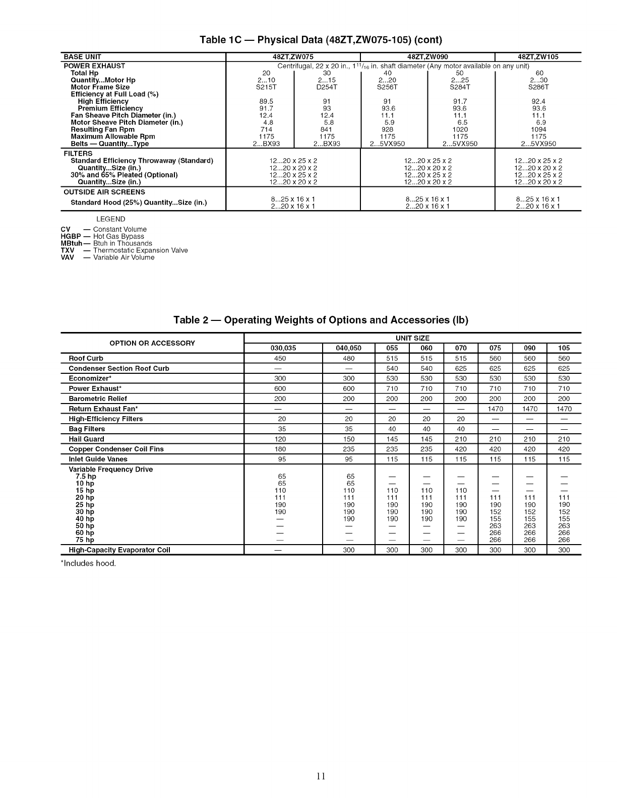
Table 1C -- Physical Data (48ZT,ZW075-105) (cont)
BASE UNIT
POWER EXHAUST
Total Hp
Quantity...Motor Hp
Motor Frame Size
Efficiency at Full Load (%)
High Efficiency
Premium Efficiency
Fan Sheave Pitch Diameter (in.)
Motor Sheave Pitch Diameter (in.)
Resulting Fan Rpm
Maximum Allowable Rpm
20
2...10
$215T
89.5
91.7
12.4
4.8
714
1175
48ZT, ZW075 I48ZT, ZW090 I48ZT, ZW105
Centrifugal, 22 x 20in.,1W16in. shaftdiameter(Any motoravailable on any unit)
30 40 50 60
2...15 2...20 2...25 2...30
D254T $256T $284T $286T
91
93
12.4
5.8
841
1175
91
93.6
11.1
5.9
928
1175
91.7
93.6
11.1
6.5
1020
1175
92.4
93.6
11.1
6.9
1094
1175
2...5VX950
Belts -- Quantity...Type 2...BX93 2...BX93 2...5VX950 2...5VX950
FILTERS
Standard Efficiency Throwaway (Standard) 12...20 x 25 x 2 12...20 x 25 x 2 12...20 x 25 x 2
Quantity...Size (in.) 12...20 x 20 x 2 12...20 x 20 x 2 12...20 x 20 x 2
30% and 65% Pleated (Optional) 12...20 x 25 x 2 12...20 x 25 x 2 12...20 x 25 x 2
Ouantity...Size (in.) 12...20 x 20 x 2 12...20 x 20 x 2 12...20 x 20 x 2
OUTSIDE AIR SCREENS
Standard Hood (25%) Quantity...Size (in.) 8...25 x 16 x 1 8...25 x 16 x 1 8...25 x 16 x 1
2...20 x 16 x 1 2...20 x 16 x 1 2...20 x 16 x 1
LEGEND
CV -- Constant Volume
HGBP -- Hot Gas Bypass
MBtuh-- Btuh in Thousands
TXV -- Thermostatic Expansion Valve
VAV -- Variable Air Volume
Table 2-- Operating Weights of Options and Accessories (Ib)
OPTION OR ACCESSORY
Roof Curb
Condenser Section Roof Curb
Economizer*
Power Exhaust*
Barometric Relief
Return Exhaust Fan*
High-Efficiency Filters
Bag Filters
Hail Guard
Copper Condenser Coil Fins
Inlet Guide Vanes
Variable Frequency Drive
030,035
450
3OO
6OO
2OO
2O
35
120
180
95
UNIT SIZE
040,050 055 060 070 075 090 105
480 515 515 515 560 560 560
-- 540 540 625 625 625 625
300 530 530 530 530 530 530
600 710 710 710 710 710 710
200 200 200 200 200 200 200
.... 1470 1470 1470
20 20 20 20 -- -- --
35 40 40 40 -- -- --
150 145 145 210 210 210 210
235 235 235 420 420 420 420
95 115 115 115 115 115 115
7.5 hp
10 hp
15 hp
20 hp
25 hp
30 hp
40 hp
50 hp
60 hp
75 hp
High-Capacity Evaporator Coil
65
65
110
111
190
190
65
65
110
111
190
190
190
300
11o
111
19o
19o
19o
30o
11o
111
19o
19o
19o
30o
11o
111
19o
19o
19o
30o
111
19o
152
155
263
266
266
300
111
19o
152
155
263
266
266
300
*Includes hood,
111
19o
152
155
263
266
266
300
11
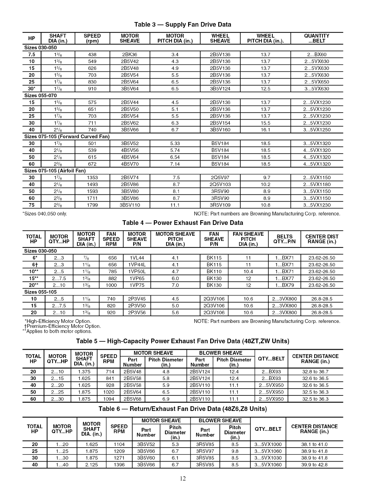
Table 3 -- Supply Fan Drive Data
IS. FTIS olooto°I OOtO°I I I OU ,t.t
HP DIA (in.) (rpm) SHEAVE PITCH DIA (in.) SHEAVE PITCH DIA (in.) .... BELT
Sizes 030-050
7.5 13/8 438 2BK36 3.4 2B5V136 13.7 2...BX60
10 13/8 549 2B5V42 4.3 2B5V136 13.7 2...5VX630
15 15/8 626 2B5V48 4.9 2B5V136 13.7 2...5VX630
20 15/8 703 2B5V54 5.5 2B5V136 13.7 2...5VX630
25 17/8 830 2B5V64 6.5 2B5V136 13.7 2...5VX650
30* 17/8 910 3B5V64 6.5 3B5V124 12.5 3...5VX630
Sizes 055-070
15 15/8 575 2B5V44 4.5 2B5V136 13.7 2...5VXl 230
20 15/8 651 2B5V50 5.1 2B5V136 13.7 2...5VXl 230
25 17/8 703 2B5V54 5.5 2B5V136 13.7 2...5VXl 230
30 17/8 711 2B5V62 6.3 2B5V154 15.5 2...5VXl 230
40 21/8 740 3B5V66 6.7 3B5V160 16.1 3...5VXl 250
Sizes 075-105 (Forward Curved Fan)
30 17/8 501 3B5V52 5.33 B5V184 18.5 3...5VXl 320
40 21/8 539 4B5V56 5.74 B5V184 18.5 4...5VXl 320
50 21/8 615 4B5V64 6.54 B5V184 18.5 4...5VXl 320
60 23/8 672 4B5V70 7.14 B5V184 18.5 4...5VXl 320
Sizes 075-105 (Airfoil Fan)
30 17/8 1353 2B5V74 7.5 2Q5V97 9.7 2...5VXl 150
40 21/8 1493 2B5V86 8.7 2Q5V103 10.2 2...5VXl 180
50 21/8 1593 3B5V80 8.1 3R5V90 8.9 3...5VXl 150
60 23/8 1711 3B5V86 8.7 3R5V90 8.9 3...5VXl 150
75 23/8 1799 3B5V110 11.1 3R5V109 10.8 3...5VXl 230
*Sizes 040,050 only. NOTE: Part numbers are Browning Manufacturing Corp. reference.
Table 4-- Power Exhaust Fan Drive Data
TOTAL IMOTOR
HP QTY...HP
Sizes 030-050
6* 2...3 7/8
61" 2...3 11/8
10"* 2...5 11/8
15"* 2...7.5 13/8
20** 2...10 13/8
Sizes 055-105
10 2_.5 11/8
15 2...7.5 13/8
20 2...10 13/8
*High-Efficiency Motor Option,
l-Premium-Efficiency Motor Option,
**Applies to both motor options,
MOTOR FAN MOTOR MOTOR SHEAVE FAN FAN SHEAVE I BELTS I CENTER DIST
SHAFT SPEED SHEAVE PITCH SHEAVE PITCH I I
D A (n.) RPM PIN DIA (in.) PIN DIA (in.) QTY._PIN RANGE (in.)
656 1VL44
656 1VP44L
785 1VP50L
882 1VP65
1000 1VP75
4.1
4.1
4.7
6.0
7.0
BKl15
BKl15
BK110
BK130
BK130
11
11
lO.4
12
12
1...BX71
1...BX71
1...BX71
1...BX77
1...BX79
23.62-26.50
23.62-26.50
23.62-26.50
23.62-26.50
23.62-26.50
740 2P3V45
820 2P3V50
920 2P3V56
4.5
5.0
5.6
2Q3V106 10.6 2...3VX800 26.8-28.5
2Q3V106 10.6 2...3VX800 26.8-28.5
2Q3V106 10.6 2...3VX800 26.8-28.5
NOTE:Partnumbers are Browning Manu_cturing Corp. re_rence.
Table 5-- High-Capacity Power Exhaust Fan Drive Data (48ZT,ZW Units)
TOTAL
HP
20
30
40
50
60
MOTOR
QT_..HP
2...10
2...15
2...20
2...25
2...30
MOTOR SPEED MOTOR SHEAVE
SHAFT Part Pitch Diameter
DIA. (in.) RPM Number (in.)
1.375 714 2B5V48 4.8
1.625 841 2B5V58 5.8
1.625 928 2B5V58 5.9
1.875 1020 2B5V64 6.5
1.875 1094 2B5V68 6.9
BLOWER SHEAVE
Part
Number
2B5V124
2B5V124
2B5V110
2B5V110
2B5V110
Pitch Diameter
(in.)
12.4
12.4
11.1
11.1
11.1
QTY...BELT
2...BX93
2...BX93
2...5VX950
2...5VX950
2...5VX950
CENTER DISTANCE
RANGE (in.)
32.8 to 36.7
32.6 to 36.5
32.6 to 36.5
32.5 to 36.3
32.5 to 36.3
Table 6-- Return/Exhaust Fan Drive Data (48Z6,Z8 Units)
TOTAL
HP
20
25
30
40
MOTOR
QTY...HP
1...20
1...25
1...30
1...40
MOTOR SPEED
SHAFT RPM
DIA. (in.)
1.625 1104
1.875 1209
1.875 1271
2.125 1396
MOTOR SHEAVE
Part Pitch
Number Diameter
(in.)
3B5V52 5.3
3B5V66 6.7
3B5V60 6.1
3B5V66 6.7
BLOWER SHEAVE
Part Pitch
Number Diameter
(in.)
3R5V85 8.5
3R5V97 9.8
3R5V85 8.5
3R5V85 8.5
QTY..BELT
3...5VX1000
3...5VX1060
3...5VX1030
3...5VX1060
CENTER DISTANCE
RANGE (in.)
38.1 to 41.0
38.9 to 41.8
38.9 to 41.8
39.9 to 42.8
]2
NOTES;
/. ROOF CURB IS SHIPPED DISASSEMBLED.
2, ROO_CURB: 14 6A, EVA03 58] STL,
3. DiHENS!ONS IN [ ] ARL NiLLIHETER5,
7" O"
[2134]
>
0"-I i/4" [32]
/0" 1 3/4"
[z4]
(TYP ALL SIDES)
r ....
i i CONDENSER
i AND
L i COMPREBSORi
I i SND i
i _ONDENSER / CONDENSER i
AND AND i
ComPRESSORis J COMPRESSORi
i No END_
8"-8 9//8"
[2048]
/
/
/
J
[78]
VIEW B
(CORNERCONNEC IONS AND
SPLICE PLA CONNECTIONS)
1/18"
[ 13731
_ [678] =
S
UNIT TYPE DIMENSION UNIT SIZE UNIT SIZE
030,035 040,050
VERTICAL SUPPLY AND RETURN A 21"-81h6" 25"-8Hh6"
WITH GAS HEAT B 13'-3H/16" 16'-05/s"
VERTICAL SUPPLY AND RETURN WITH A 23'-9V4" 27'-95/16"
GAS HEAT AND EXTENDED CHASSIS B 15'-47//6" 18'-17/8"
Fig. 1-- Roof Curb; Sizes 030-050
UNIT LEVELING TOLERANCES
÷Fr'om edge oF n t 0 _or" zor" a,
o
_S
£W
_b
t
COUNTER FLASHING
_(F/ELO SUPPLIED)
Z
NOTES_
i, ROOF CURB 15 5HIPPcD DISASSEMBLED,
2, ROOF CURB: 14 @A.[VA03 563 5TL.
3, DIMENSIONS iN ] ARE MNL[METERS,
A 5UGGLSTLD isOLE LOCATION bOR FIELD WIRING
THROUGH ROOF CURB(BOLLS TO BE 5UPPLIFD
BY FIELD),
o" 3 _
BASE RAIL CROSS EOT ON
TYP ALL BASE RAILS
5CA E 1 = 3
7"-0"
[2134]
5" 7]/4"
[1 o8} -
O" 3 //2"
[88}
CONDENSER END SUPPORT
ON T LEVELINO TOLERANCES
_Fr, om edge o un to hop zontoL.
-I i/4" [32]
i3/16" [2/5]
7/8" [22.35]D
LOW VOLTAGE
(BEE NOqE #4)
/0" I 3/4"
[4a]
(TY D ALL S!DEB)
8" _0@8 °
[1191]
/
• 2_
[358]
LCONDENSER
AND
COMPR 580R
END
_/
L----
]CONDENSER
1 AN',3 I
COHPRESSOR !
r ""_f
CONDENSER
AND
COMPRESSOR
END
_-0"-10 1/i6"
[258}
(TYPICAL 4 CORNERS}
<
6" 8 g/l@
(2046)
"m
_0" -3"
[763
Vl W B
(CORNERCONNECT ONS AND
SPICE PATE CONNECI/ON8)
UNIT TYPE DIMENSION UNIT SIZE
055-105
VERTICAL SUPPLY AND RETURN A 27'-9H/ld '
WITH GAS HEAT B 22'-10shd'
VERTICAL SUPPLY AND RETURN WITH A 29'-107/8"
GAS HEAT AND EXTENDED CHASSIS B 24'-113/d'
s
_8
Fig. 2 1Roof Curb; Sizes 055-070 and Sizes 075-105 without High-Capacity Power Exhaust
%
ROOFING FELT
/(FIELD SUPPLIED)
/
/{I CANT STRIP
(FIELO BUPPLIED)
NO1ES:
i ROOFCURBISSHIPPEDDiSASSEMGLED
2,ROOFCURB:i4GA,iVADG-56]STL
3,DIMENSIONSiN[ ]AREMILLIMETERS,
4,SUGGLSTEDHOLLLOCATIONFOR_IELDWIRING
THROUGHRO0_CURB(HOLESTOBESUPPLIED
BYFIELD_
b,PACKAGECURBAS¥P/NCRR_CURBOiGADD
o5"
8ASLRAILCROSSSPCTION
TYPALL5ASRALS
SCAr:3
JG'67/32=_
J [1987}
689/16"
2046]
VIEWB_
ENDSUPPORT
O'5I
[144]
3443/4"
[10483]
5"73/4'
[1721}
COUNTER FLASHING
_(R_ELD SUPPLIED)
ROOFING FELT
_(F_EID SUPP_ED)
30 7/8"
[1191}
/Lo o/16'
256t J
{TYP CAL 4CORNERS)
RIGID _NSULAIION
(FIELD SUPPLIED}
Fig. 3 -- Roof Curb; Sizes 075-105 with High-Capacity Power Exhaust
"_'_O' 3 _'
{76}
VIEW B
(CORNER CONNECT!ONS AND
SPL!CE PLATE CONNECTIONS}
CONI)ENSER i
AND i
DOMP SOR
CONDENSER
AND
COMPRESSOR
END
T-q
CONDENSER ]
AND z
COMPRESSOR I
END z
A_
T
DEG,
O
DIMENSIONS
(degrees and _n(hes)
A B
iN, DEG,
20 SO
UNI_ LEVE_ING _OLERANCES
*Prom edge DE uni_ to horizonia_,
IN
75
NOTES,
1, ROOF CURB ACDESBOR v £B SHIPPED DISASSEMBLED.
2, DiNENSiONS IN E ] ARE MILLIMETERS.
3. ROOF CURB: /4 BA.[VA03 SB] STL,
BOO_ CURB PANS_ 1B GA, EVAO3 BE] STL_
J
[SO}
_[76] _
o,..3 _
BASE RAI CROSS SECTION
TYP ALL BASE RAILS
BCAE 1 : 3
3/16"
V1EW B
(CORNER CONNECTONS AND
SPLCE PLATE ¢ONNECIONB)
1/2" X 2" SEAL STRIP-\
TYP BOTH SIDES
_-OUTLINE OF UNiT
iCONDENSER
SECTION SUPPLY
AIR
\\_PLAN VEW OF ROOF CURB TANDAR ROOF CURB
ATTACH TO ROOF CURB WITH
/i/4 20 SELF DRILLING SCREWS
/
/
i/2 _ X 2 _ SEAL STRIP
F-}-¸
DIMENSIONS _
(degr'ee_s and ncne_s)
A B
DEO, N. DEG, IN,
1.0 20 0 , B
UN T LEVELING TOLERANCES
• _pon edge oF n t o hopizontaL,
ol/8 _ X I" SEAl_ STRIP
_STANDABD ROOF CURB
/
A_
1/8 _ X 1" SEA _ STRIPn \\\\
CROSS SUP_OR T_
SECTION A A
(TYPICAL 2 PLACL5)
SCA'E i:3
A
8" 03/4"
E2458]
_SPLiCE PLATE
SEE VIEW B
_WOOD BLOCKING
X 1 _ BEAL STRIP
1YP BO1H SIDES
(SDPPL/EO WITH CURB}
Fig. 4 -- Condenser Section Roof Curb (Size 055 and 060 Only)
RIGID
(FIELD SUPPLIED)
_-ROOFING FELT
(FIELD SUPPLIED)
/
STRIP
SUPPLIED}
MATERIAL
(FIELD SUPPLIED)
NOTES;
I. ROOF CuRB ACCESSORY IS SHIPPED DISASSEMBLED,
2. DIMENSIONS £N [ ] ARE MILLIMETERS,
B. ROOF CURB= i4 GA,_VAO3-SB] STL.
ROOF CURB PANS: iB GA.[VA03 SB] BTL.
_.!_72_ _3/1B_
[SO]
O' I 1B/1B"
o' 3"
BASE RAIL CROSS SEC ION
TYP ALL BASE RAILS
SCALE 1 =3
ViEW B
(CORNER CONNECTIONS AND
SPLICE PLATE CONNECTONS)
7"-0"
2134]
[783
_OUTLINE OF UNiT
CONO NSER} SECTION i
PLAN VIEW 0 ROOF CURS
SUPPLY
AIR
q
\
SIANDAPD ROOF CURB
ATIAEH TO ROOF CURB WIIH
_'1/4-20 SELF-DR£LLING SCREWS
/
/r_JJ x _° SEALSTRIP
/
1/' 0 9//B _
E3367]
/' B _
3S6]
.4
SEE V1:W B
SPLICE Pl ATE
(SUPPLIED WITH CURB)
RiGiO
(FIELD SUPPLIED)
_5TANDARD ROOF CURB
/
_-SPLiCE PLATE
/
/
_WOOD BLOCKING
_-i/8" X I" SEAL STRIP
TYP BOTH BIDES
COUNTER FLASHING
(FIELD SUPPLIED)
/
CANT STRIP
_i[IELD 5UPPL[ED)
MATERIAL
(FIELD SUPPLIED)
I/8" X 1 _ SEAL BTRIP-_ \
\
CROSS SUPPORT _
SEC]ION A A
(TYPICAL 3 PLACES)
SCALE I_3
A_
f£
DIMENSIONS _
(degrees aria inches}
A B
DEG. iN, DEG. IN.
1.0 2.0 ,50 ,75
UNiT LEVELING TOLERANCES
÷FPo_ edqe o? unit to hopizontaL.
Fig. 5 -- Condenser Section Roof Curb (Size 070-105 Only)
CONDENSER
END SUPPORT
DETAIL A-A
Fig. 6- Gasket Location on Roof Curb (48ZG,ZN055-105 and 48Z6,Z8075-105 Units)
Fig. 7-- Gasket Location -- Condenser Section Roof Curb (Size 055-105 Units)
18
CONDENSER
END SUPPORT
4 REF,
DETAIL A=A
Fig. 8 -- Gasket Location on Roof Curb (48ZT,ZW075-105 Units)
NOTICE TO RIGGERS
1. ALL PANELS MUST BE IN PLACE WHEN RIGGING.
2. DO NOT ATTEMPT TO FORK THESE UNITS.
WEIGHT A B ECONOMIZER
UNIT Ib kg in. mm in. mm Ib kg
48Z030 5770 2623 83.23 2114 176.14 4474 300 136
48Z035 5895 2679 83.23 2114 177.99 4521 300 136
48Z040 6670 3032 92.64 2353 205.87 5229 300 136
48Z050 6710 3050 92.64 2353 207.01 5258 300 136
NO E _
R 8 W B OUR CABLES AND _\
SPREAD WITH TWO 95 IN (2413 HN) \A
ANO TWO "AqA" I ON6
BUI ABLE SPREADER BARS_
CENTER OF 8RAVITY INCLUDES ECONOHIZER A _._//
UNIT WEIOHT DOES NOT ]NCDE ECONOHIZER,
Fig. 9 -- Rigging Label -- Size 030-050 Units (Standard Chassis)
49,8 INCiE :_ E 163 HM]
19
NOTICE TO RIGGERS
1. ALL PANELS MUST BE IN PLACE WHEN RIGGING.
2. DO NOT ATTEMPT TO FORK THESE UNITS.
WEIGHT A B ECONOMIZER
UNIT Ib kg in. mm in. mm Ib kg
48Z055 8,820 4009 128.75 3270 235.0 5969 530 240.9
48Z060 9,120 4145 128.75 3270 235.0 5969 530 240.9
48Z070 9,550 4341 112.50 2858 252.0 6401 530 240.9
48ZG,ZN075 10,445 4738 127.80 3247 260.6 6618 530 240.9
48ZG,ZN090 10,655 4833 127.80 3247 262.4 6666 530 240.9
48ZG,ZN105 11,385 5164 127.80 3247 271.0 6883 530 240.9
48Z6,Z8075 11,915 5405 127.80 3247 260.6 6618 530 240.9
48Z6,Z8090 12,125 5500 127.80 3247 262.4 6666 530 240.9
48Z6,Z8105 12,855 5831 127.80 3247 271.0 6883 530 240.9
\B
NO/I:
RIG WIT1 FOUR CABLES AND
SPREAD W TH TWO 95 IN (24 3 HH)
AND TWO "A_A" lONG
S(J TABLE SPREADER BARB, A
CENTER OF GRAVITY ]NQUDES ECONOH]ZER, _. /
UN T WE]GIlT DOE NO7 INCLUDE ECONOMIZER,
Fig. 10 -- Rigging Label- Size 055-105 Units (Standard Chassis)
NOTICE TO RIGGERS
1. ALL PANELS MUST BE IN PLACE WHEN RIGGING.
2. DO NOT ATTEMPT TO FORK THESE UNITS.
WEIGHT A B ECONOMIZER
UNIT Ib kg in. mm in. mm Ib kg
48Z030 6270 2844 95.83 2434 192.56 4891 300 136
48Z035 6395 2900 95.83 2434 194.72 4946 300 136
48Z040 7170 3252 105.24 2673 222.44 5650 300 136
48Z050 7210 3270 105.24 2673 223.50 5677 300 136
\B
NOTE
RIO WITH FOUR CABI ES AND "'<-\
SPREAD WI1 t /WO 9B N (2413 NN} "A
AN[) /WO "A+A '_ ONG
SLJITAB E SPREADER BARS,
O NIER OF (3RAYIIY INCLUD S ECONOMIZERu
UNI] WE OH[ DOES NOI INCLUDE :CONONiZER.
>
45.8 INCHES [11{43 MM]
LNIT WEIGHT IS WITHOUT REC AIN COIl......
Fig. 11 -- Rigging Label -- Size 030-050 Units (Extended Chassis)
20
NOTICE TO RIGGERS
1. ALL PANELS MUST BE IN PLACE WHEN RIGGING.
2. DO NOT ATTEMPT TO FORK THESE UNITS.
WEIGHT A B ECONOMIZER
UNIT Ib kg in. mm in. mm Ib kg
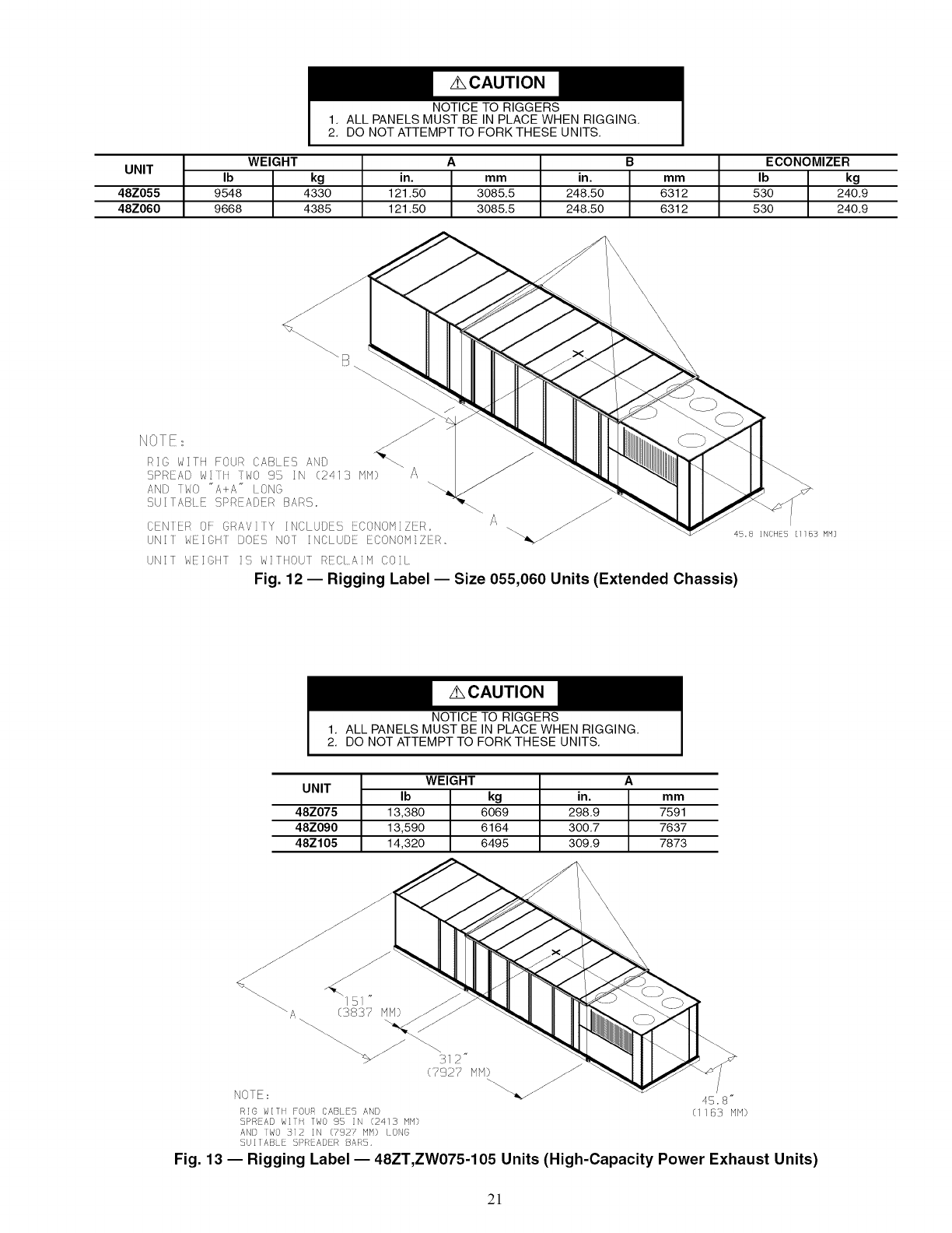
48Z055 9548 4330 121.50 3085.5 248.50 6312 530 240.9
48Z060 9668 4385 121.50 3085.5 248.50 6312 530 240.9
NOTE_ _-_
RIO WITH FOUR CABLES ANO "_\.
SPREAD W t WO 9'5 IN (2413 NP1) A
AND 1WO "A+A" LONG
SUlTAB E SPREADER BARS_
CEN ER OF GRAVlTY INCLUDES ECONOMIZER.
UNII WE oHr DOES NOI INCLUDE 80NONIZER.
A
UNIT WEICHT !S W!THOUT RECIA!N COIl_
Fig. 12 -- Rigging Label -- Size 055,060 Units (Extended Chassis)
NOTICE TO RIGGERS
1. ALL PANELS MUST BE IN PLACE WHEN RIGGING.
2. DO NOT ATTEMPT TO FORK THESE UNITS.
WEIGHT A
UNIT Ib kg in. mm
48Z075 13,380 6069 298,9 7591
48Z090 13,590 6164 300,7 7637
48Z105 14,320 6495 309,9 7873
(792 M)_
NOTE _ 4S. 8"
R!6 WITH FOUR CABI S AND (1183 NN)
SPR AD WIll IWO 95 N (2413 MM}
AN[} IWO 312 IN (£92? HH) LONG
SU IABLE SPREADER BAt_S,
Fig. 13 -- Rigging Label- 48ZT,ZW075-105 Units (High-Capacity Power Exhaust Units)
2!
f
B
2 ,_
©
4
1
UNITS 48ZG,ZN
VERTICAL SUPPLY AND RETURN/
LOW GAS HEAT
VERTICAL SUPPLY AND RETURN/
HIGH GAS HEAT
VERTICAL SUPPLY AND RETURN/
EXTENDED CHASSIS/LOW GAS HEAT
VERTICAL SUPPLY AND RETURN/
EXTENDED CHASSIS/HIGH GAS HEAT
SIZE
030
035
040
050
055
060
070
075
090
105
030
035
040
050
O55
O6O
O7O
O75
O9O
105
O3O
O35
O4O
O5O
O55
O6O
O3O
O35
O4O
O5O
O55
O6O
CORNER WEIGHTS (Ib) TOTAL
1 2 3 4 (Ib)
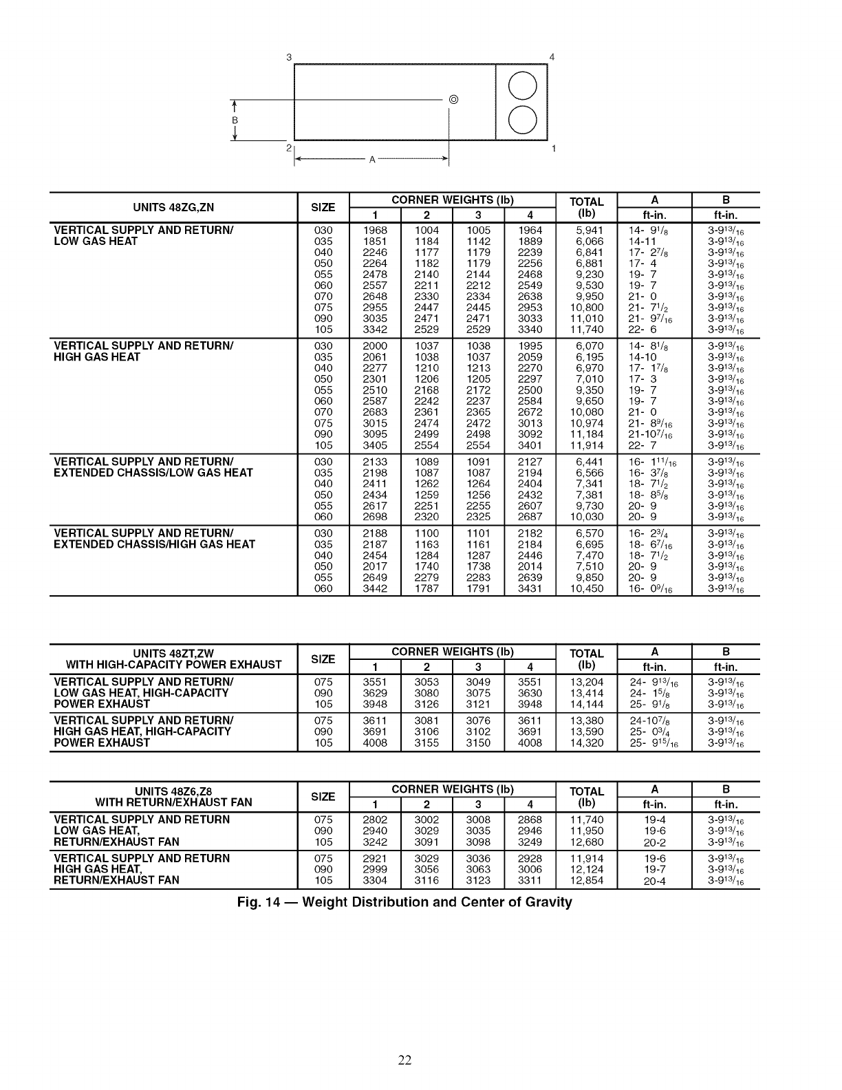
1968 1004 1005 1964 5,941
1851 1184 1142 1889 6,066
2246 1177 1179 2239 6,841
2264 1182 1179 2256 6,881
2478 2140 2144 2468 9,230
2557 2211 2212 2549 9,530
2648 2330 2334 2638 9,950
2955 2447 2445 2953 10,800
3035 2471 2471 3033 11,010
3342 2529 2529 3340 11,740
2000 1037 1038 1995 6,070
2061 1038 1037 2059 6,195
2277 1210 1213 2270 6,970
2301 1206 1205 2297 7,010
2510 2168 2172 2500 9,350
2587 2242 2237 2584 9,650
2683 2361 2365 2672 10,080
3015 2474 2472 3013 10,974
3095 2499 2498 3092 11,184
3405 2554 2554 3401 11,914
2133 1089 1091 2127 6,441
2198 1087 1087 2194 6,566
2411 1262 1264 2404 7,341
2434 1259 1256 2432 7,381
2617 2251 2255 2607 9,730
2698 2320 2325 2687 10,030
2188 1100 1101 2182 6,570
2187 1163 1161 2184 6,695
2454 1284 1287 2446 7,470
2017 1740 1738 2014 7,510
2649 2279 2283 2639 9,850
3442 1787 1791 3431 10,450
A
ft-in.
14- 91/8
14-11
17- 27/8
17-4
19-7
19-7
21- 0
21- 71/2
21- 97/16
22- 6
14- 81/6
14-10
17- 17/8
17-3
19-7
19-7
21- 0
21- 89/16
21-107/16
22- 7
16- 111/16
16- 37/8
18- 71/2
18- 85/6
20- 9
20- 9
16- 23/4
18- 67/16
18- 71/2
20- 9
20- 9
16- 09/16
B
ft-in.
3 -913/16
3 -913/16
3 -913/16
3 -913/16
3 -913/16
3 -913/16
3 -913/16
3 -913/16
3 -913/16
3-913/16
3 -913/16
3 -913/16
3 -913/16
3 -913/16
3 -913/16
3 -913/16
3 -913/16
3 -913/16
3 -913/16
3 -913/16
3 -913/16
3 -913/16
3 -913/16
3 -913/16
3 -913/16
3 -913/16
3 -913/16
3 -913/16
3 -913/16
3 -913/16
3 -913/16
3 -913/16
UNITS 48ZT, ZW
WITH HIGH-CAPACITY POWER EXHAUST
VERTICAL SUPPLY AND RETURN/
LOW GAS HEAT, HIGH-CAPACITY
POWER EXHAUST
VERTICAL SUPPLY AND RETURN/
HIGH GAS HEAT, HIGH-CAPACITY
POWER EXHAUST
SIZE
075
090
105
075
090
105
CORNER WEIGHTS (Ib) TOTAL
1 2 3 4 (Ib)
3551 3053 3049 3551 13,204
3629 3080 3075 3630 13,414
3948 3126 3121 3948 14,144
3611 3081 3076 3611 13,380
3691 3106 3102 3691 13,590
4008 3155 3150 4008 14,320
A
ft-in.
24- 913/16
24- 15_
25- 91_
24-107_
25- 0 3&
25- 915/16
B
ft-in.
3 -913/16
3 -913/16
3-913/16
3 -913/16
3 -913/16
3 -913/16
UNITS 48Z6,Z8
WITH RETURN/EXHAUST FAN
VERTICAL SUPPLY AND RETURN
LOW GAS HEAT,
RETURN/EXHAUST FAN
VERTICAL SUPPLY AND RETURN
HIGH GAS HEAT,
RETURN/EXHAUST FAN
SIZE
075
090
105
075
090
105
CORNER WEIGHTS (Ib) TOTAL
1 2 3 4 (Ib)
2802 3002 3008 2868 11,740
2940 3029 3035 2946 11,950
3242 3091 3098 3249 12,680
2921 3029 3036 2928 11,914
2999 3056 3063 3006 12,124
3304 3116 3123 3311 12,854
A
ft-in.
19-4
19-6
20 -2
19-6
19-7
20 -4
B
ft-in.
3 -913/16
3 -913/16
3 -913/16
3 -913/16
3 -913/16
3 -913/16
Fig. 14 -- Weight Distribution and Center of Gravity
22
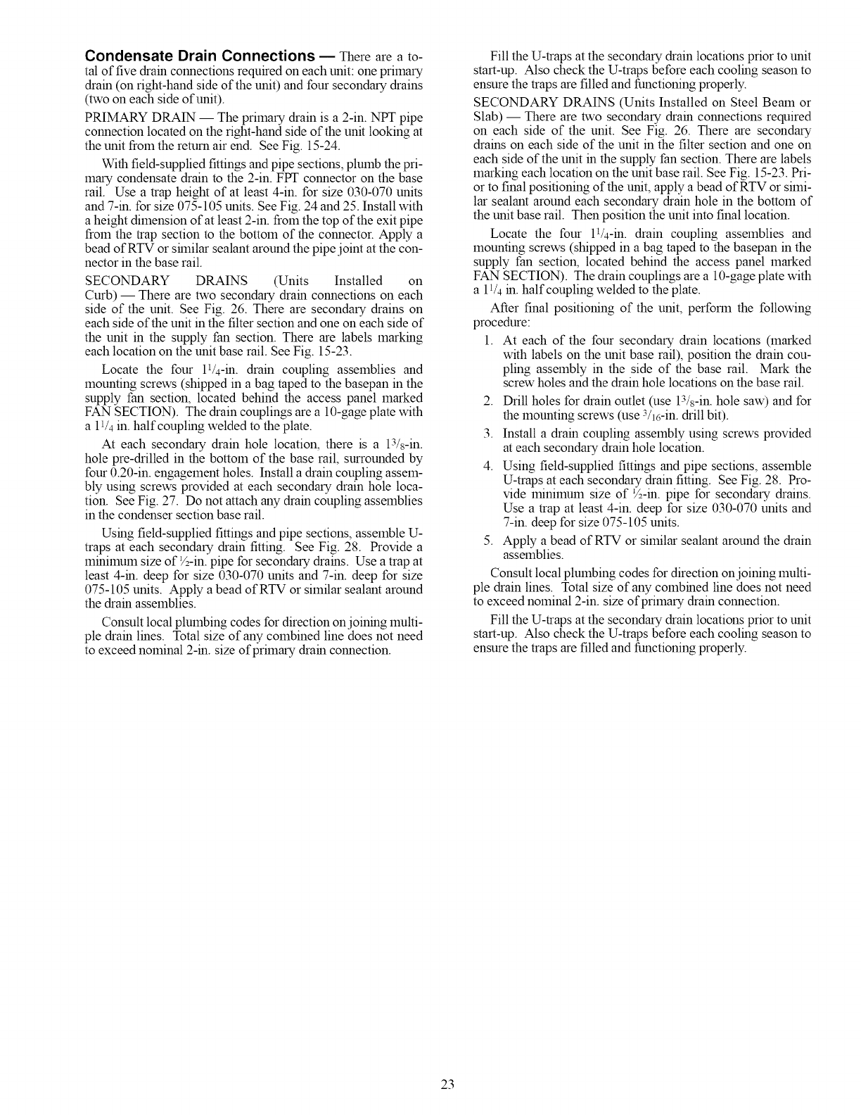
Condensate Drain Connections -- There are a to-
tal of five dram connections required on each unit: one primary
dram (on right-hand side of the unit) and four secondary drains
(two on each side of unit).
PRIMARY DRAIN -- The primary drain is a 2-in. NPT pipe
connection located on the right-hand side of the unit looking at
the unit from the return air end. See Fig. 15-24.
With field-supplied fittings and pipe sections, plumb the pri-
mary condensate drain to the 2-in. FPT connector on the base
rail. Use a trap height of at least 4-in. for size 030-070 units
and 7-m. for size 075-105 units. See Fig. 24 and 25. Install with
a height dimension of at least 2-in. from the top of the exit pipe
from the trap section to the bottom of the connector. Apply a
bead of RTV or sfinilar sealant around the pipe joint at the con-
nector in the base rail.
SECONDARY DRAINS (Units Installed on
Curb) -- There are two secondary dram connections on each
side of the unit. See Fig. 26. There are secondary drains on
each side of the unit in the filter section and one on each side of
the unit in the supply fan section. There are labels marking
each location on the unit base rail. See Fig. 15-23.
Locate the four P/4-m. drain coupling assemblies and
mounting screws (shipped in a bag taped to the basepan in the
supply fan section, located behind the access panel marked
FAN SECTION). The drain couplings are a 10-gage plate with
a 11/4in. half coupling welded to the plate.
At each secondary drain hole location, there is a 13/s-in.
hole pre-drilled in the bottom of the base rail, surrounded by
four 0.20-in. engagement holes. Install a drain coupling assem-
bly using screws provided at each secondary drain hole loca-
tion. See Fig. 27. Do not attach any dram coupling assemblies
in the condenser section base rail.
Using field-supplied fittings and pipe sections, assemble U-
traps at each secondary drain fitting. See Fig. 28. Provide a
mmilnum size of ½-in. pipe for secondary drams. Use a trap at
least 4-m. deep for size 030-070 units and 7-in. deep for size
075-105 units. Apply a bead of RTV or similar sealant around
the dram assemblies.
Consult local plumbing codes for direction onjoining multi-
ple dram lines. Total size of any combined line does not need
to exceed nominal 2-m. size of primary dram connection.
Fill the U-traps at the secondary drain locations prior to unit
start-up. Also check the U-traps before each cooling season to
ensure the traps are filled and functioning properly.
SECONDARY DRAINS (Units Installed on Steel Beam or
Slab) -- There are two secondary dram connections required
on each side of the unit. See Fig. 26. There are secondary
drams on each side of the unit in the filter section and one on
each side of the unit m the supply fan section. There are labels
marking each location on the unit base rail. See Fig. 15-23. Pri-
or to final positioning of the unit, apply a bead of RTV or simi-
lar sealant around each secondary drain hole in the bottom of
the unit base rail. Then position the unit into final location.
Locate the four 11/4-m. drain coupling assemblies and
mounting screws (shipped in a bag taped to the basepan in the
supply fan section, located behind the access panel marked
FAN SECTION). The drain couplings are a 10-gage plate with
a 11/4 m. half coupling welded to the plate.
After final positioning of the unit, perform the following
procedure:
1. At each of the four secondary drain locations (marked
with labels on the unit base rail), position the drain cou-
pling assembly in the side of the base rail. Mark the
screw holes and the drain hole locations on the base rail.
2. Drill holes for drain outlet (use 13/s-in. hole saw) and for
the mounting screws (use 3/j6-in. drill bit).
3. Install a dram coupling assembly using screws provided
at each secondary drain hole location.
4. Using field-supplied fittings and pipe sections, assemble
U-traps at each secondary drain fitting. See Fig. 28. Pro-
vide lnimmum size of ½-m. pipe for secondary drains.
Use a trap at least 4-in. deep for size 030-070 units and
7-in. deep for size 075-105 units.
5. Apply a bead of RTV or similar sealant around the drain
assemblies.
Consult local plumbing codes for direction onjoining multi-
ple drain lines. Total size of any combined line does not need
to exceed nominal 2-in. size of primary dram connection.
Fill the U-traps at the secondary drain locations prior to unit
start-up. Also check the U-traps before each cooling season to
ensure the traps are filled and functioning properly.
23
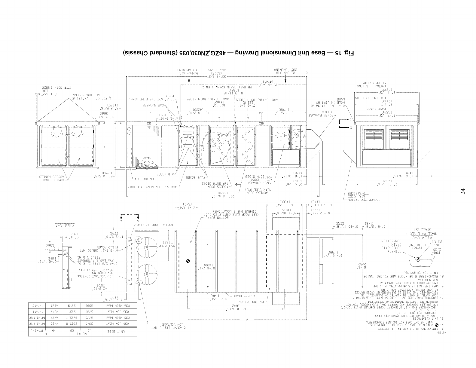
(s!sseqo pJepuets) S_O'O_ONZ'DZ8_ -- 6u!MeJO leUO!SUeUa!Ot!uN ese8 -- SL"6!_
ON NdO LO@@ <HV_I 3SV8 ONN_dO 3@@
_J V i Jdc@S /64% _ V HI@ :_ 0
.9/c 9 ¸ ,Si ..................................................
0 S_iA NNO0 NiVdC] iHVHi!:ld
[_89_]
_9:/LL 8 ,@
[8"O% i
'NN03 3dici 5V9 LdN ._ ,0 ¸ S_aiS HiO@ 'NIV_@ X@V i_@i_ HiO@ 'NiV_@ XCW
[_088i [9 Ldd]
_U_Nd[]@ .OL .OL =_/{ £,i
{.9 _7- j I60/Li
JL/i 0 .EL ...................................................................]......................._ .......................3L/S L .S ..................
$ S
"Hig { Nid<:N HS
3Ni / I i lWLI?0
,,_/i 1¸¸¸,9
qqO I NO : i [ _K}d 9N i iJ [ I
0 F:_ LL , i
"bE_ ;' .8,"8 •\ ..... i
RiO " j t,_tT_] j
LSqVHX_ -hOd7 \ _=_.......................................7/ /.................................._j
/4 F-
/ u---- o
619_ _69_
{EgE 99_8
&'_898 04iS
9"_9_8 0P98
9X 81
.@/i @ ,_L @@b_
"HI J HH
V
IdN [L_@L] ._/8=0
IV_H iigibl _80
IV_H i_9iH 080
_ZIS iiN@
iZ] ]
/' IL,'E{ -i . L_
/
/
, S_@i_; (E) dXi
_ _@OOii _:V
" NO:idO _I_TiHON(}3_
..... ;, /dd '_ OliO@ i..............................................
{ i' ":1[/ OL ," .9L/Z S-.('
........................................................................ Z 3'_ 3S
4,-"J' _ NO I" \Oq "?'<
(L3} /[/;'d _+8
/........................................................ 3"'13 t,
11 ] r -- -- ..... j N/%_C] .S/ 0L ,7 x" Z_
I :: : ! o ,so I _ _,z'
I i _., !-. " -
I ,b/ OL ,"_L7
Ii l ',,, ii i (1 N{ } (I lOD 3tJ%' (}(}OH'9 lddiHSIiS7i i_,ONooO£liN@ '
iS_ 1Okl IVW
i I J _i/,,cIS NO3 iSfiilX@_ a N{_ ,L_OAOVS
iL -- _ -- ! ..... I , 3 I )r'l "@ IIF/OH @v! i/ qi HI N ¢ "
ti " ...... €- _ ' x x_'.'"s'.,,," ;x" x -
it [ 2 : i ; s, vt8 ._13 ,i ]£RI0 <hi_ _8 >idMQ H !aNIH,,10OII;
! t%/ XR_ OO@ qq£]O iSI il '39_,NSq@ NO @tiNFOH Si iIN@ £1 +8730 SOOt
l " i// 0 / i ki};] 11% 0 (ii)_ ?( O 07N9 ;OU 0rio )IINS)I "
l.... ,>n £I ,0 08 ' [•iH3Hitld7@ 9NItI3NIDXt NOIi<'OI IddV !31tt,,3
7¢9_ ............................................ i KIViN00 'I7]IO\iVkP/IiI0 lVq0ll_,di[id0 OHV I]01,R£F UIIID,'HS kK):i
i . 0- 0 Siih i'_'HXt _Ii ()< NOX O 9 (flq taZ: 0,03q
: ....................................................................... . iI L/,_ i ,L .............................................................. !: i ............ =...... oO ,9 SSIlS
=o ,9 @N] XOt IOIIIN03
r{Ivl IlIi;,i£'dNO3 I3RIiSIII£I iON O8 d01
k_...................................................................................................V ..................................................................................................: SIOiid,'3]O iiNq '{
'!3ZII/ONOOI SQn iOSl iON S}O@ iFI9[11_ iIN/I
-- 9Vi iO', N0 ] +Lt£ZIHOH0OII i£(}qq3Ni ki i'VS9 10 .qiiiNiO _ E
'5tii£>,llqqZbl NI IS<,' [ ] Hi 5NOlINS_d@ '
:SiLOi
,q-
t'q
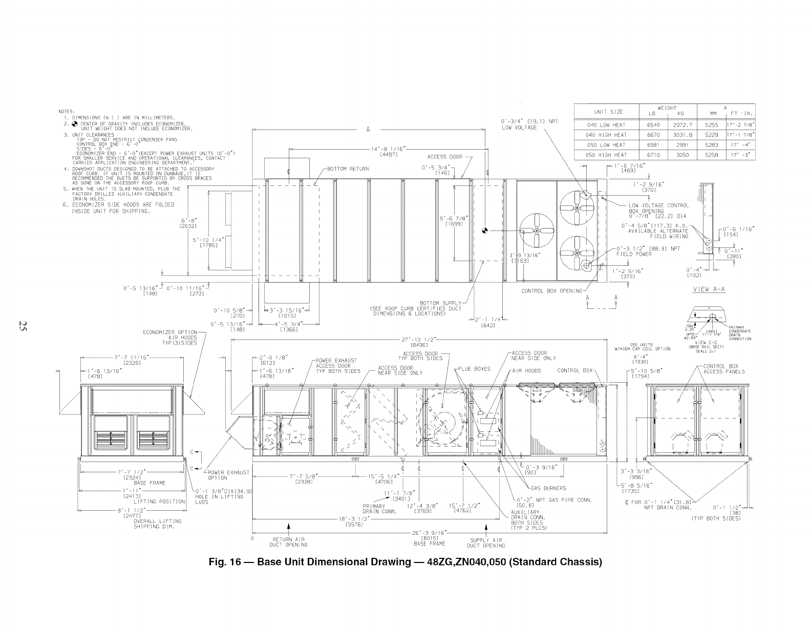
I'O
NOiES;
i. O]MENSION5 IN [ ] ARE IN MILLIMETERS,
2_ _ CENTER OF GRAVITY _NCLUDES ECONOMIZER,
UNiT WEIGHT DOES NOT INCLUOE ECONOMIZER,
3, UNIT CLEARANCES
TOP - DO NOT RESTRICT CONDENSER FAN5
4,
S,
B_
CONTROL BOX END 8" O_
SIDES 8' O"
ECONOMIZER END 6' O'(EXCEPT POWER EXHAUST UNITS 10" 0")
FOR SMALLER SERVICE AND OPERATIONAL CLEARANCES, CONTACT
CARRIER APPLICATION ENGINEERING DEPARTMENT,"
OOWNSHOT DUCTS DESIGNED TO DE ATTACHED TO ACCESSORY
ROOF CURD, IF UNIT IS MObNTEO ON OUNNAGE,_T _S
RECOMMENDED THE DUC15 BE SUPPORTED BY DROSS BRACES
AS DONE ON THE ACCESSORY ROOF CURB.
WhEN THE OMIT IS SLAB MOUNTED, PLUG THE
FACTORY DRILLED AUXILIARY CONDENSATE
BRAIN HOLES,
ECONOMIZER SiDE HOODS ARE FOLDED
INSIDE UNiT FOR 5BIPPING,
6"_8 _
[20323
5" lO 1/q'i i
[178B]
[478]
O'-S 13//8 "J O'qO 11/16 "_
[!48} [2723
ECONOMIZER OPTION_
AIR HOODS /
TYP(3)SIDE5 /
[148]
s'-5 3/4"
[1366]
_2" O i/8 _
[B12]
BOTTOM
(SEE ROOF CURB CERTIFIED DUD1
DIMENSIONS 8 LODATION5)
0"-3/4" [19,I] NP]
LOW VOLSAGE
ACCESS DOOR FLUE BOXES
f- NEAR 51DE ONLY HOODS
\\\
\\
\\\
\
UNIT SiZE
040 OW HEAT
040 HIGH HEAT
OSO LOW HEM
OSO HIGH HEA!
CON ROL BOX OPENING _
A A
WEIGHT
LB KG
6540 2972.?
6670 303i,8
658i 289i
6710 3050
A
MM FT IN. i
B2BB _7"-2 7/8"i
5229 i7" i r/S'i
B283 /7' _4 _
5258 i7' 3"
_-i"-B 7/18"
[4893
i" 2 9//6"
[370]
_LOW VOLTAGE CONTROL
BOX OPENING
0"v7/8" [22,2] BIA
0"-4 B/8_[117.B] K,O,
AVAILABLE ALTERNATE -0'-8 i/1B"
FIELD WiRiNG [154]
/0' 3 1/2" [88,9} NPT O' 11"
FIELD POWER [280]
1" 2 9//6 _ 0"_4_;_ _-' i
[370] [i02]
VIEW A-A
ODO UNTO
W/HIGH CAP COl OPTON
8" 4"
[!g30]
CON]ROL BOX_
\\
_ ........
L_CONDBNSA1E
¢2,83 CONNECTmN
V_EW C_C
(BASE_A}L SECT)
SCALE2,/
/
_?'-? i/2"--> /-POWER EXHAUST
[2324] k OP}!ON
BASE FRAME
7'-11" _i O" I 3/8"DIA[34,9]
[24133 i HOLE IN LIFTING
LIFTING POSi#lONi LUGS
B'-I ]/2"
[2477]
OVERALL LiFTiNG
SHIPPING BiN.
¢
7" 75/8" 15' 5 1/4"
[23281
9/16"
[90]
[470B] i
//" l_T/B _
[340/]
PRIMARY /2" 4 3/8" 15' 7 i/2"
DRAIN CONN, [37893 847523
18" 3 i/2"
[BBTB] _ BOTH 5IDES
(TYP 2 PLCS)
< 2B'-3 9/18"-----------------------------------
R TURN AiR [8015] SUPPLY AIR
DUCT OPENING BASE FRAME DUCT OPENING
BURNERS
_0"-2 _ NPT GAS PiPE CONN.
[50, 83
Fig. 16 -- Base Unit Dimensional Drawing -- 48ZG,ZN040,050 (Standard Chassis)
3"-3 '3/1B_\
[9gB]
L5"-8 5/16"
[1735] _\
¢ FOR 0"_I _/4"[3/,_ _'_
NPT DRAIN CONN_ O" i
[B8]
[TYP BOTH SIDES)
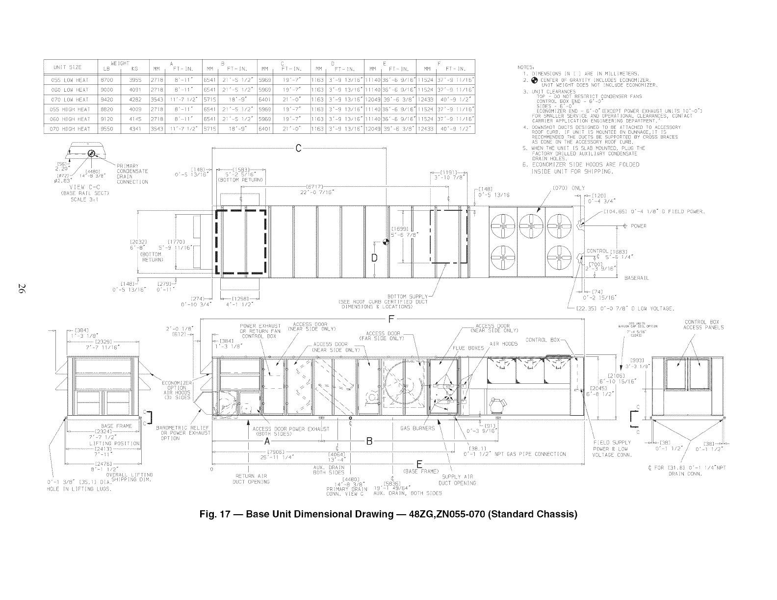
_E IOH J ,s B (} ) E E
UN i Z LB K@ Hi F I N. H /F - N_ IfiF/ F' iN. _ :T N. HH F N. if!bl F i.
O_S LOW NEAT 8¸700 3!15!_ 2718 8r 11 " 6541 2i" S i/2" 59@9 19 "¸¸;'" i@3 3" 9 13/16" 11i403@' @ 9/i@' 11524 3¸7"¸9 ii/16 '
0@0 LOW HEAl 9000 q09i 27i8 8' il _ @S41 2i" _ i/2" 59@g i9' 7" i@3 3' 9 13/16" 1114036' 8 9/i@" 11524 ]?' g ii/1E"
OFO LOW NEAT 9420 4282 3543 i/'¸7 i/2" 571b 18' 9" @401 21" O" i@3 3" 9 13/i6" 12049 39"¸@ 3/8" 12_33 40" 9 I/2"
055 I/@lq iiEAi¸ 8820 4003 2F18 B' i1 _ @5/-1 Pi" S i/2" 59@ a 19 r 7" i@3 3' 9 13/18" ili403@' @ @/i@' 1/52/, i?' 3 ii/1@'
060 ill@li iiEAi 9i20 qi!G 27i8 8" i1" 6541 2i" b i/2" 59@9 i9" ?" i@3 3'9 13/16" 1114036'¸6 9/i@' 11524 37" 9 ii/1@'
070 I1@11 iiEA_ 3S50 4341 35/-3 i1"¸¸¸¸? I/2 _ 5?!S 18' 9" 5401 21' 0 _ i@13 3' 9 13/18" 12043 33" 6 3/8" 12433 40" 3 lip °
¢2 8,"
VIEW (} C
(BASF PAl EC }
SCAI : 3_ i
CONN C ON
C
_: [1% I ;; _d
O' 5 3/i@" 5"v2 5/ @ i
{BOI iOt! RETURNI j
NOIES:
i. D 4EN OI, S N ] 5RE [Iq M LI'q TERG.
CENiER OF: GRA'_,! l Y INCLUDES ECONONiZER.
UNiT _dEi@HT DOE5 NOT iNCi UDE ECONOHiZER,
3, UNIT C EARANCE5
lOP DO NOi ¸ PESiR/CT C(}ND_N_R FANS
CONIRO_ BOX FN© @" 0 _
SIDE5 v @' 0 _
FCONOH[ZEi_ EN[} @' O" (@XCEPl ¸ POWER _XliAUSi LiNE _S 10' 0"}
FOR SNALL R SERVICE AND OPERAi!ONA_ CLEARANC S, CONiACi
CARRIER APP iCA1iON FNGiNE RiNG DEPAR]HEN_.'
_. DOWNS!IO/ DUC/S DESIGNED TO BE AiiACIIED TO ACCESS(}RY
ROOF CURB. iF UNiT iS HOUN ED OH BUNHA@ _i_ ;5
R_COHH_NBcD !HL DdCFS BE SbPPOR _B Bv (}ROSS BRACES
AS [}ONE ON FHE ACOESSORY ROOF CURB.
5_ _ilEN ql UNI lS 5LAB HObNTED, P t)C TiiF
_ACiORY DRILLED AUXI_!ARY CONDENCAI
[}_AiN iiOL ES.
@_ ECONOH/ZER S] DE li('OD! :] ARE FOI D@D
INSiBE UN]_ -OR cI_IPPiN@_
.......................................i <_" i _I j , <070ON
/l C" 4 /4"
', i ,
!/TxI L/-x
_s_ j I coc<
OtL_
i I U '
:ss ..... l
,s" / " " 4
O" 5//@ _
O' 10 3/4 _
< [38q1 2' O i/8 _
i"3 i/8" t612]
........... [123291 ...............
?'-7 il/i@"
[2478]
8' i I/2"
OV R/,IL i FlINt;
O' .</s3" 3t:. O /; ' tiPP NC D H
IO E IN I F N3 U3 ,
2111LII
[[258/ J
4' i i/2"
I>OWEI/ EXi ,sU£ I
(}R RNURN PAN
OONTROI 80X
/
/
BO I(}H S,JPPLY /
(S E ROOF CJRB CER ]FiED DUC/
D]V@NS]ON 8 (}CAT K}NS}
,\3C $5 }00R
<NE!;R 5iDE ONLY;
// / _\CC: _:} DOOR
F
RETLRN A R [4480] @ 5UPP Y ,_ ]R
DUO[ (}PIING 4' 8 3,'8" 5818J D,JCT OPEi' NO
PR]H&RY DR&IN 19" i 49¸/64"
[22,}i 3' 0 Z,/8 # D LOW ',0 TAG ,
Fig. 17- Base Unit Dimensional Drawing- 48ZG,ZN055-070 (Standard Chassis)
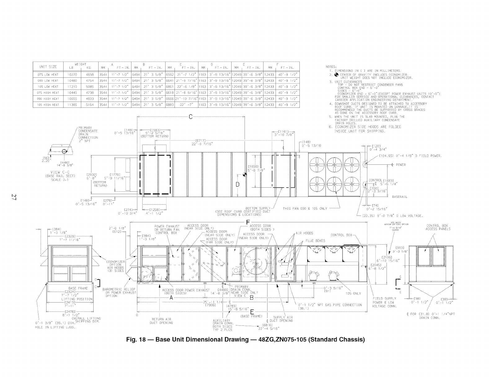
---I
072 0,', dEAT ]0 70 46_8 ZN4 I" 7 I/2 _ :}4}'4 " /8" @/D i" /" 11_3 3" 13/15" ] 047 39" { £/8" 1.4]3 40' t i/>'"
090 LOW ilEAl ]0480 4Z84 3D44 1i"¸¸¸? I/2" 6494 2i" 3 5/8" @@4/ 2]' g 7/i8 _ //B3 3' B /3/i6 _ iP049 39' B 3/8 _ />433 40' g i/2 _
i05 OW HEAT 11210 5085 354/_ 1i"¸7 I/2" @494 2_" 3 5/8" 6851 22"¸@ i/1!" 11@3 3" 8 13/i@" 12049 39' @ 3/8" 12433 40"¸9 i/2"
O_B iilCl_ I_BAT 10448 _F38 3_44 1i" _ I/2" 6494 2i' 3 5/ii" 6@/8 2i' B 9/18" //@3 3' _ /3/18 _ 120_9 3!i' B 3/8" 12433 40' 9 i/2"
090 _ilGli liEAi i0@88 4833 354_ ii"¸¸7 1/2" B49 L Pi' 3 5/8" @5@@ 2!" ]0 ?/i6"/ 1@3 3" 8 13/!B" 12049 39' @ 3/8" 12433 40"¸9 i/P"
I0_ ii1@i HBA[ ii38B 5i6_ 3_44 1i' ? i/2" 6494 2i' 3 B/B =@883 22' 7 _ 11B3 3' _ /3/16" IP049 39' B 3/8 _ /P433 40' 9 ]/2 _
/,'
/
_R [ h<AiRY
( ONN N%A ]
ORi_ N
CONNED I /ON
2" RPl
S' 2 /6 _
O' 5 13//8 _ (BDT {}I R fJRN)
i
220" [480]
i4" 8 3/8"
',/]E_'_ C C
( AtE Rail i:Cb
_@FIL :l
[20321
@'B _
[ 143 ]
NOIE8;
1. BP" N /ON N [ ] iN N { ]HEIERB.
,_ _'_:N i E R @_A,/y Tv TN("I i:CONn_ iZ R
.JiG'H6L'J "N_L O'_6iZR.
3. (N (}I[A_A (} S
TOP 90 NOT RESTRICT CONDENSER AN8
CONIRO BOX ND _" 0
BIDES _' 0"
FCONOH[Z R EN D B' O"(EXC P P%R EXSAUST UN[ B 10' 0 °)
F}:_ *_4/'11 R fRVlD: ,S,ND Os:#,NION,U ([&RAN(:, (}ON A(T
C,S R!ER APP JCAT ON ENOII'EER O BFPAR 'qENT '
4 B@NSHOT DD 8 DES GNED TO BE ATTAC D TO ACCESSORY
ROOF CURB. UN/ 5HOBN ED ON DkJN A@I ,X
RBCO:"VENB O i BkC BIr %PPORIED BY ORBS8 BRACI8
A DO",F ON {iF ACCE ORY %0 CUR .
,. ,dlEN {BE UN T b LAB OUNIE@, PlUG E
_sCl()Rv [Ri I ED AJX/I RAY CON{ '\S/4E
DAN IlOEt
(. CON@'/ Z R (;O [ODI ARE FO BED
N:}I[E UN/[ FOR } PPN@
>[3_4i
[148i j
O' 5 i3/i6"
0 ' fi 0 3/4" 4 " i /2"
/
/
/
8o1 oN iilpl v /
( EF 00 Ckk>i GFRTi iD DiET
}IN NB:ON _ iOCAi IONS)
THIS AN 090 _{ ]OB ONL%....................I
POW R EXt,RST £(}Oli [ )OBR
OR RFTURN FAI' (N!::LR _DE ONI Y)
CONi RDL BOX
F
...............sCCES8 DOOR
@O[H SIDES )
AD(X!!SB DOOR
/,,,
O" 2 1B/18"
{22_ 38) O" 0 D'B" B :OW 70LT£_[L
B' i i/2"
OV RALI / iF1 /NO
0'/ 3/8" 3 11 DI&SIi{PPING BIN
fiOL_ iN LiFI/N6 LdGB.
ECBNOBJZER
OPiiON
AIR IIO01)S
(31 SIDES
/
/i
BAROISETA!C RELIEF i
OR POWER EX!iAU}]!i
OPTION i
J ACCE5B DOOR i(IW R !X A(,i! - [4480J DR,s, CONN.
(BO ili 8 / DiS)
@ \ 0" 1 1/2 =NH G#3 PIE DONN/(}iiON
I ?BO@] [478!i] _
15" -8 B/i 6 _ '_ [38, i ]
j! X
:_E[ORN AR ,RJXi AR' _} OCT OPEN NC
DLJ('I OPENING {)RAIN C(N!,
Vl> 2 > 3 ' 4 A6"
Fig. 18 -- Base Unit Dimensional Drawing -- 48ZG,ZN075-105 (Standard Chassis)
€
POiER iOW /[38]
O' I ,0" /O'q I/S
//
@ FOR [3!8i O" i 1/4"1PT
i)RA IN BONN.
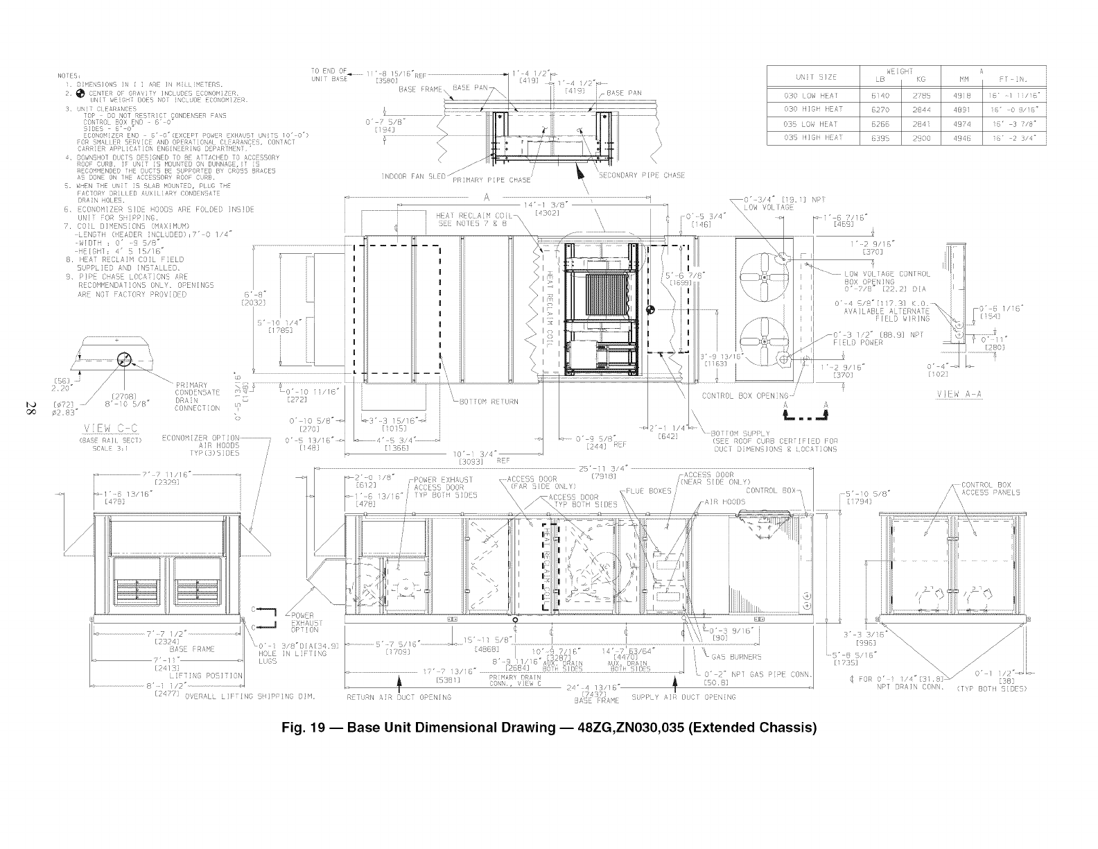
;NISiZE
030I ,,NEA!
030Nil lEA
0 0_',IIEA
03:It/NiI A
WE]OHJ
B dO
@1402785
6270 2844
52@8284i
8399 2900
A
HH
qN8
489i
4974
qt48
b! iN,
18" 1 11/i6"
i@" 0 _/S@"
16' 3 7/8"
S6" 2 3/4"
5. ,'HEN THE N T S SI£B bO NTED, Pit6 THE
F A¢f ORY DR i L L ED &UX i1 [ ARY CON[)[!NSA iE
DRAIN HOLES.
8, CONOM S!} HO0}S ,_R F()Li) D NS }
i.......................................i _..........................................iB
\
i!
Ty C3) ii DES
'/
i
k,, (}..,-._-J EXNAU5
OPT i ON
,\
' 0" i /8"1} AI 4.
IIOLE iN Li TIN@
[LOS
[ 477 O,,ERaLL LIF: iN@ ]P N@ OiF/,
_0' 3/4" (19,i3 N [
\\\ L O,s VOI I AGF
O' 5 3/4"
[ 46]
COq[ROL BOX OPENING
L.=.J
[@421
10'i3/
[30931 RLF
5' i I 3/4"
_2" 0 /8" i I>(!W :/ XHALSI (_ IN ACCE%S 30(11_
'(NIAR '}i[) OI )
CON ROL BOX\
BO 0 1,1>> '
(SEE RO0: CURB CEI/TN::IED FOR
DUO1 DiMENSiON c _ i O()A1 i(INS
..................., %_ ,,.......................I,:,_._,_u:..................................!..............................................................._...............................................
"_1, -I ,S 266 E ' _q_!3 '/`' 'L "'_,S ,I_N Ik
_,/" c _ X 8b_T AUX. DIW_ /
.............................,._.:_//,,! ........,,,,__, ............,,_.. ,, ,,_ ,,_ CONN.
t_ 15:8 ] CO ,, ',/[,, C ,_ -SO.82/" q 1 p!@" !
? _ LPP Y i" ()kC OPEN NC
R TL,RN ,',R D,CT OP NING A:} ::@s,q
}' ]o !/8"
i ]iYlq]
,< CONTRO BOX
/' \\ _CCF55 P&NEL
// "
t
.....:/
_x
C381
NPT DRAIN CONN, (T_P BOTll SIDES)
Fig. 19 1Base Unit Dimensional Drawing 148ZG,ZN030,035 (Extended Chassis)
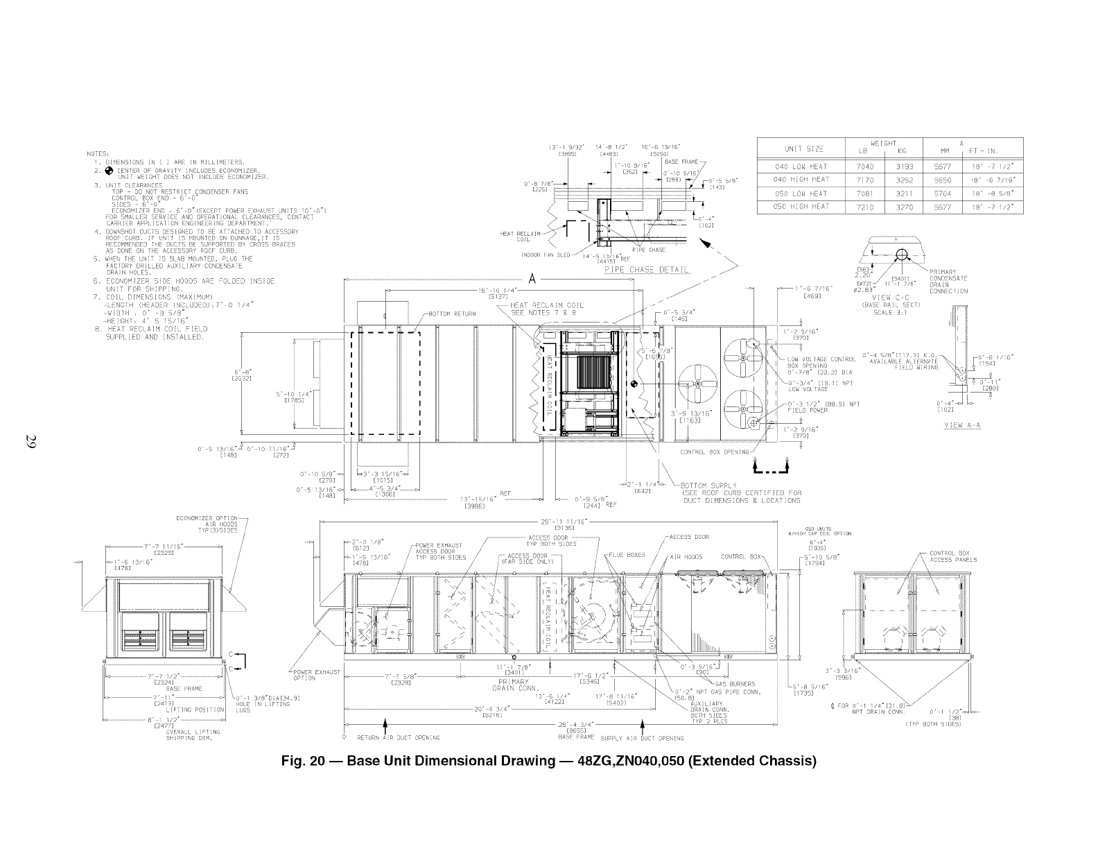
i3" / )/3J 4 8 //" /{" 8 13/ ("
ig97J [44{ 37 [{0 SO]
i"¸10 S/iS" 8,tSE FR_d_E7
I _ ES2] r |or:: C //!_
o., ,,-_ _ / i _1......_,, ,8-
[2_ / 4_
........ , °_
o \ _lLa "-_
.J P,i c:_ \ \
NOOR iAf {O //4 g /f_R
IOTES, M N N
i. [)_ E ISjOi! N { ] ARi N MILl /fEYERS
2. _ CENTER OF Gf_A,,']/Y iNELUbES ECONOMIZER.
UNiT _E{SHi DOES NOI INCLUDE ECONONIZER,
3_
cofr OL bOX _f _' O"
bilE:, E' o"
E ONONI/E£ {NO 'o"c{xc;Pr POS,,ER XlA r UN]r: 10' O°7
FO {HAL {ER {{RV{OE AN[ OPERAr iONAL CL AR/_IkC , CONTAC[
CARRI{R APi iCAIIO\ ENGiN[ERI\G DErART ENr.*
<+ OO77ff, lOT DUCT, B77131 D TO E ATTAOil D TO /,,CO FOR_
0_ f c
I4OOF OR{. IF { [ f7 !'Od T{[{} O,NNAGE, T
R{COI_M{\[}ED Til OLD r\ [7 5UPfORTTID 8Y CRO{5 {RDCE
_5 {ON ON 71E ACC %50RY ROOf CU [;.
S. ,,iEf TiE LNiT IS I AB IOUNT B, PLUG TIE
F_CIOi_Y DRILLED AUXILIARY: CONOENSArE P/l:>E (}HA_E I)i}] J A ]{ .//>
^
8. ECONO_JZER 8iOE ilOOO8 ARE FOLDZD {NS{OZ ....................................................................................................................................................._ -_
UNTT FOR SliiPPiNG. i6" i0 1,'4" //-///"
7. COl{¸¸ DIMENSIONS (FAXIMLJN) [5137] .//
{.ENGIEI (H_AOER iNCLUOEO) ,7" 0 I/4" i .........HEAT REEL ,_f:'/ COfL
WiO]H : O' .9 8/8" • i .BorroH R_rURN SEE NOTES 7 g 8 /
iil (1i : 4' /i("
8, ED _ CLA!'/ COL I LO
.................................. :" 5/5" h...............
[59883 i 44] IRE
3/<: -
:=_7" 7 11,'1B"i=
[2329]
UNil SIZE
O40 LOW HEAT
040 HiGH HFAT
OSO LOW iiEAT
850 HiGH iiEA
WEIGHT
L8 K@
7040 3193
7170 3252
708i 32ii
72i0 3270
E24 ?Z]
OVENALI L FLING
SHi _F'IN6 Ol_.
A
HH FT iN,
5877 s8' ? liP"
5650 18" 6 viiG"
8/04 ]8" 8 5/8"
_7_Z2 18' ? i/2"
OON/ROi {OX ()}{N NG /
L.....i
88TTGM SUPPt. '¸
(_]EE ROOF CtJR{7 ('ER i iF i{TD F OR
DUCT DiHENSiON8 _ lOCATIONS
BtJRNEAt
\o" 2: PT GAS PiPE CONN,
CONN.
BOr!l 5!DE5
lTYP :7 PLCS
28" 4 3/4" •
[8855] l
i_ASE FRAME SUPPLY AiR ouor OPENING
\\ \\
(_ FOR 0" 1 i/4_[31 S_
NPT OR_tiN CONN• 18
IVP OH ICES)
Fig. 20 1Base Unit Dimensional Drawing 148ZG,ZN040,050 (Extended Chassis)
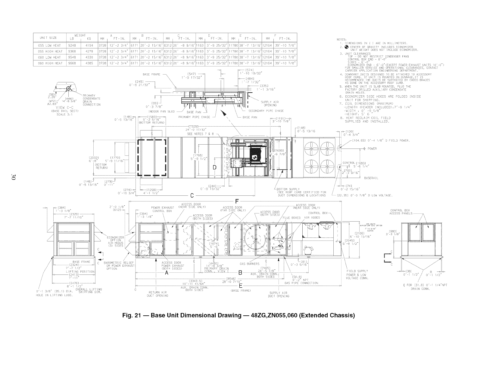
0
A[ IOl I
K N!i
0!5 LOM iIit,] i 1241 4 4 } 2_
05_, HIOH HEAT i 9388 45178 3728
OBO LOW HEAT i 9S48 4330 3728
060 HiOH HEAT i 9688 438S 3728
/, \
12"2 3 '£" j 1 20' > Ii/i("i6]12 0" 8 9,'1 "1113) 3" £ 21/32"j11J(O 11" ' 3/18"12114 3!" lO /"
12" 23/ " 1817 20' 2 15,, 6"16312 dO" 8 9/18"i1183 3" 9 25/31"111780 38" ? 3/i:%"2184 39" i¢, 7/8"
T 4 _
12" 2 3/4" j817 20' 2 15/6"6312 0" 8 9/i8_1183 3" 8 25/'32"i11780 38" 7 3/16"i184 39" i0 7/8=
12" -_/" i 17 0'2 1 /6" 312 30" 'S 9/=1123 2' ]5/ 2"i1178'028' 7 3/ _," I 4 9" 0 7/!!"
Bt, [Rt_ _ . --I
[ 4- ; I \ I II I "_ /sJ
0' c 2/32 ] s_]
14/ _=_ < [i $81 i_4
o" sis){i" ' 2 s/t," i
i (B T()H _ 1(_,)1
PRifHkR PIPE 011AsE _ \ ' B,z!!{ I>AN -_ [11 11 ,-
\ 3' i0 7/8"i
7" ? ll/l "
2"-0 i/8"
[612] _: ,
C
/0" iI 41/64"
28" 0 ?/lB*
OUOT OPENING DUCi OPENING
0" 2" N >
NOES
i, DilgEN IO S IN i i /,RE i HiLLiHErlRS.
2, _ CENlER GF GRt',I Tf INCLUDES ECONOMIZER¸
UNI_ WEIGH1 DOES NOT¸ iNCI UDE E(X)NO_I/ZER.
3, UNI T Cl EARANCES
lOP I)G NO_¸ RESiRiCi C(INI)ENSER FANS
CONTROL DOX END _' O"
SLOES _-" O"
4. OOidNSHOl DIG1S I}ES](NEO i o E s Y] £CHEO TO sCOE S()RY
ROOF: CURB, _: ki_iT [S !40U/YED ON DUNNL_GE,i i5
i_ECi)_'IHENDEI) i HE DLJCi_ B_ SUPPOi_iED _Y CROSS BRACES
AS DONE ON [HL ACGFSSORY ROO_ CURB¸
S. _qtEN Ti_E U[_IT iS SLAB t4OUNTED, PLUG THE
FACTORY DRILLED sUXiLiARY CONDENSATE
8. LCONO_iZFR 5ID- IOODS ARL -OLDEB iNSiD-
UNi[ FOR SHIPPING,
7, COIl¸¸ DiHENSiONS (HAXiN'J M)
LENGTi4 (i4_ADER iN(}IuOED):7" 0 i/4"
ii iGliY: _,' 8
8, iq A} RCLA M COI IE D
_aLpDI ED AND IN TAi [ cD,
[22.35i O' 0 7/8" ) IOi _()1 [AIE.
F Fil) SL_PI Y
POWER & LO;,)
VG ,:fie CONN.
CONI ROL BOX
z/CCE? S p/tNil Sp,,
I
ii \--.
_d >1381
0' /"/O' I/ "
//
F3R 21 .8 3,' i 1/4"NRT
:: iN SONN.
Fig. 21 iBase Unit Dimensional Drawing 148ZG,ZN055,060 (Extended Chassis)
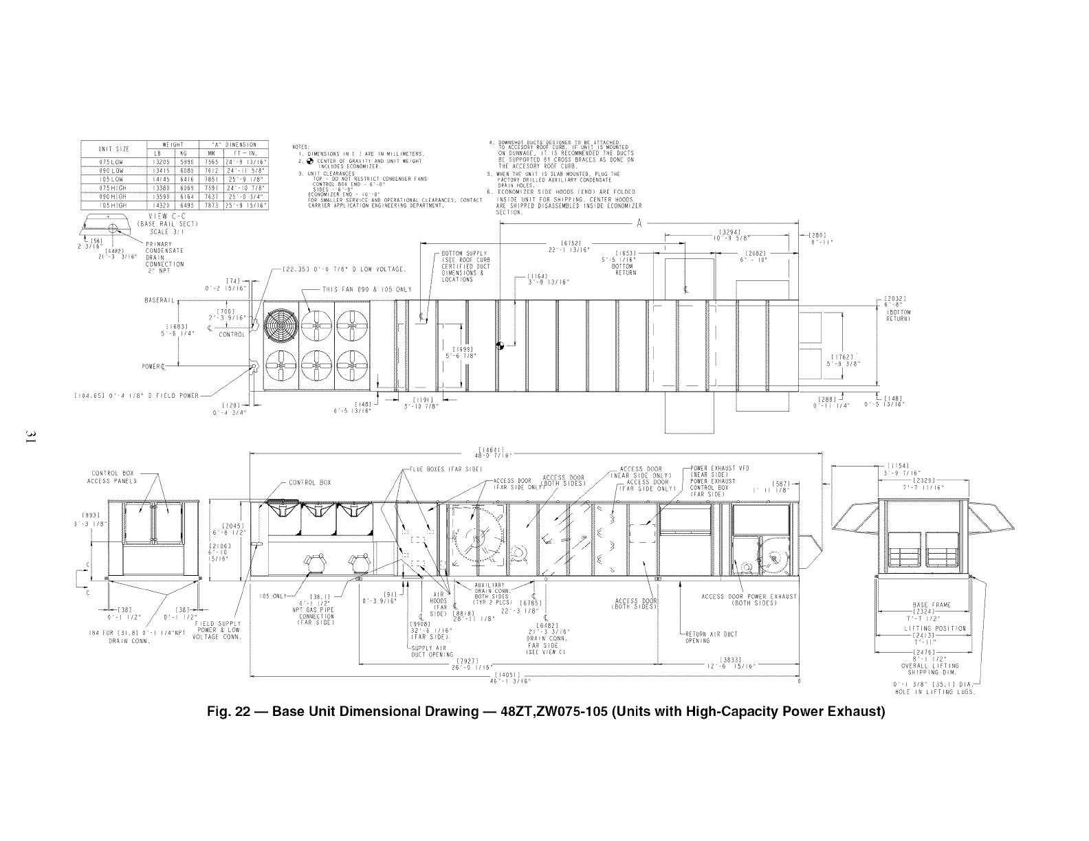
BASERAIL
0 4 3/4 _
NOTES:
I DIMENSIONS IN [ i ARE IN _ILLI_ETERS
2_ CENTER OF GRAVITY AND UNIT WEIGHT
fNCLUDES ECONOMIZER
3 UN_/ CLEARANCES
TOP DO NO] RESTRICT CONDENSER FANS
FOR SMALLER SERVICE AND OPERATIONAL CLEARANCES, CO_TACT
CARRIER APPLICATION ENGINEERinG BE_ART_ENT,
- BOTTOM SUPPLYf
I(SEE ROOF CUR8
/CERTIFIED DUCT
DIMENSIONS &
LOCATIONS
5" 6 7/8"
4 BOWNSO/ D_.C/SBESIG'_EDTO B ATTAC ED
TO ACE SOR_ ROOFCRB, IF UNIT IS _OUt_IED
ON DUNNAGE, IT _S RECOMMRNBEBTBE DUETS
8E SUPPORTEDBY CROSS BRACES AS DONB ON
THE ACEESORY ROOF CURS,
SWHENTHE _NIT IS SLAB MOUNTED,PLUG i_E
fACTORY D_ILLED AUXILIARY CO_DE_SATE
BRN_NHOLES,
6, ECONOMIZER SiDE HOODS (END) ARE FOLDED
_BS;DE UNIT FOB SHIPPING, CEBTBB HOODS
ARE SBIPPED DISASSEMBLED INSIDE ECONOMIZER
SECTION, A
o E_p,,,
[2881 _ [48]
O" I 114' O' B 13/16 =
CONTROL
ACCESS
/\
[993]
3 3
El i
/
o _ f/2" /o' i i/2"
// FIELD SUPPLY
i84 EOR {318] O I I/MNPT POWER & LOW
VOLTAGE CONN
DRAIN CORN
-CONTROL BOX
ACCESS DOOR _POWER EXHAUST VFD
_(NEAR SIDE ONLY) (NEAR SIDE)
DOOR _ POWEREXHAUST
J EONIROL 80X i li i/8 _:
[38, i7 j
O' i _/2"
NPT GAS PiPE
CONNECTION
(FAR SIDE)
, o
BOTH SIDES
( Y 2 PLCS) 678_]
SBE) /8'
[92908_" [6'82
1116' 2 '-3 316'
(FAR S DE) DRAN CONN<
SPPLY AIR FAR S DE
DUCT OP NNG (SE( YEW D)
[7927]
26' O ilB"
[lADS1
_6'- 3/16
i
ACCESS DOOR POWER
(BOTH SIDES)
-RETURN AiR BUCT
OPENING
{3833]
12'-6 15/!6'1
Fig. 22 -- Base Unit Dimensional Drawing -- 48ZT,ZW075-105 (Units with HighiCapacity Power Exhaust)
BASE FRAME
T' 7 _/2"
LIFTING POSITION [
[724i 31]_ I
'-i " [
{2476]_
8'"i _/2" [
OVERALL LiFIlMG I
SHIPPING DiM, !
0 i 3/8" [35,i] 81A, J
HOLD IN LIFTING LUGS
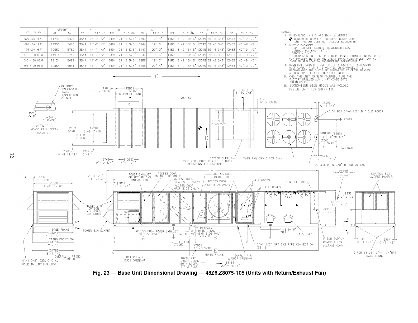
UNilS!ZE
07b LOW mEAT
090 LOW HEAl
lob _OW mEAT
O75 HIGH HEAl
090 H_GH MEAT
los HIGH HEAT
WEiGHF
LB i KG
11740 i 532b
11950 i 5420
12D80 i 579P
11914 i B742
12124 i sa99
12854 i B831
A
HM I FT IN,
3544 i_'-7 i/2"
3544 11" 7 I/2"
3544 iI _ 7 i/2"
3544 11"-7 I/2"
3944i i1" 7 i/2"
3544 11"-7 i/2"
B
MM i
D4s4i 21
BASS i 21
2/
B494 i 21
D4941 21
B494 i 21
/
FT N. I HM
"3 Y8" 5893i!
•:_s/B" _:s94
., ./B"iBlq
", SWB"pBBB!
• :_BwB"_s_r3B
° I B
FT N. MM FT IN,
9" 4" 183 =r 9 13/6"
9" B" 1BBii _" 9 13/.B °
20" 2" iNGJj3" 9 13/i6 _
9" 6" 163 3" 9 13/B"
19" 7" /'/63 3" 9 13/6 _
O" 4" 163 i; 3 ' 13/ "
E i F
MH FT IN, [ MH FT IN,
1204c 39 6 R/8" 2433 409 1/2"
1204939" 6 3/8" 933 40" 9 //2 _
1204939'6 3/8"2433 40'_9 I/2 _
PR MARY 4 "
/CONDrNSA1F 1 8_ r_ 1583]_ _,
BRA O" 5 13//8_ I 5' 2 S//D
2.[58120 CONNECTONv E £ [_8°]/8_" " NP1 1{901"OM RURN)| "
o_, 17o H I]
(BASE PAL SEC ) B' 8 _ *-9 1 /B'_ I ] I
SCALE 3; / (BOTTOM
C4B]_ -2797_
o" s lS/;D" o" is"
264.5T
__ 5"-8 7/8 _
"@
D
[274]_ BOTTOM SUPPLY
(SEE ROOF CURB CERTIFIED DUC1
O" !0 3/4 _ 4" 1 //2" DIMENSIONS 8 LOCATIONS}
NOTE5:
1, DIMENSIONS iN [ ] ARE JN MILLIMETERS,
2. _ CENTER OF GRAVITY INCLUDES ECONOMIZER_
UNiT WEIGH1 DOES NOT _NCLUDE ECONOMIZER,
3. UNiT DLEARANCES
TOP DO NOT RESTRICT CONDENSER FANS
CONTROL BOX END 6" O"
SIDES - B'_O _
ECONOMIZER END _ D'_O_(EXCEPT POWER EXHAUST UNITS iO'_O')
FOR SMALLER SERVICE AND OPERATIONAL CLEARANCES, CONTACT
CARRIER APPLICATION ENGINEERING DEPARTMENT,"
4, DOWNSHOT DUCTS DESIGNED TO BE ATTACHED TO ACCESSORY
ROOF CURB. _F UNII iS MOUNIED ON DUNNAGE, iT iS
RECOMMENDED THE DUCTS BE SUPPORTED BY CROSS BRACES
AS DONE ON THE ACCESSORY ROOF CURB,
5. WHEN THE UNiT iS SLAB MOUNTED, PLUG THE
FACTORY DRILLED AUXILIARY CONDENSAFE
DRA}N HOLES,
6, ECONOMIZER SIDE HOODS ARE FOLDED
INSIDE UN_I FOR SHIPPING,
F
_ 3ms 2' 0 1/8" [
7,, _/1_- //
l
OP ON
/i :]
c_ /
POWER EXH DAMPER
/LIFTING P@B ; T I_N I
, 7 1 _
/ 8"I/2 _
/ OVERALL LIFT NG
O" 3/8 _ EBB, ] O A. 5 PP NG DIM.
OLE IN lIFT N8 LUGS,
i [148]
O" b 13/i6
V
, \
\
T S FAN 090 g lob ONLY
_[120]
O" 4 3/4"
[I04.85] O" 4 i/8 _ D FIELD POWER.
/
i@POWR
BASERA_L
O" 2 i5/16 _
[22.35] O'_O 7/8" D LOW VOLTAGE.
F
POWER EXHAUST _CSE_n_O_R _ ACCESS DOOR
mR RE1URN FAN (NLA_ _uc _NLY) /(BO]H SIDES )
"%ONfROL BOX /_ACCESS DOOR /ACCESS DOO_ AIR HOODS
'_[384} \ / /(NEAR BiDE ONLY) /,"_ _ CONTROL BOX\
I" 3 i/8" \ / /ACCFS5 mOOR /(NEAR SIDE ONLY)/ \ F \
°_ \. ./TqPA_,£0_L? . . /_, LUEBO,ES .\
-1 111 ( %qll;d k IIit itY/AA /I'C..i"C.,'101I
1 _, n ill _!_ t -. ii k- ,_-- >_q ,-..,
/\CCLSS BOOR POWER EXHAOST [4480] iDAAIN CONN, \ \ 9_s "' _ \
(B3 -_ S_OE5) _ 14" 8 3/8_INEA£ SiOE ONLY \ \ • I05 ONLY
2B.,,i/. -_ .........................................................................\_ \
{TgO@] [47B3] \ O" l 1/2" NPT GAS PIPE CONNEO[ION
/(BASE FRAME) I S_PPLY AIR
RETURN AIR AUXILIARY ¢ DUCT OPENING
DUCT OPEN_NG DRAIN CONN.
BOTH SIDES ....... _ [B81B]
TYP 2 PLC5 22"_4 5/18"
07B UNITS
_/HIH CAP COl[ OPT{ON
7' 4 SITS +
S24Si
/
[204B] ...........
s'-s_/2"1
1/1 _ c
5,
FIELD SUPPLY
POWER _ LOW
VOLTAGE CONN,
CONTROL BOX
ACCESS PANELS
O" 1 //2" 0"-I 1/2"
/
@FOR [3/.8] O'-I 1/4"NPT
DRAIN CONN.
Fig. 23 -- Base Unit Dimensional Drawing -- 48Z6,Z8075-105 (Units with Return/Exhaust Fan)
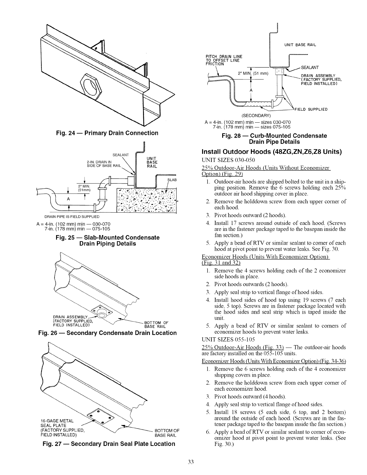
PITCH DRAIN LINE
TO OFFSET LINE
FRICTION
2" MIN (51 mm)
UNIT BASE RAIL
DRAIN ASSEMBLY
FACTORY SUPPLIED,
FIELD INSTALLED)
Fig. 24- Primary Drain Connection
SEALANT UNIT
2-IN. DRAIN IN BASE
SiDE OF BASE RAIL RAIL
DRAIN PIPE IS FIELD SUPPLIED
A = 4-in, (102 mm) min -- 030-070
7-in, (178 mm) min --075-105
Fig. 25 -- Slab-Mounted Condensate
Drain Piping Details
SLAB
DRAIN ASS
(FACTORY SUPPLIED, BOTTOM OF
FIELD INSTALLED) BASE RAIL
Fig. 26 -- Secondary Condensate Drain Location
16-GAGE METAL
SEAL PLATE
(FACTORY SUPPLIED, -----.--BOSOM OF
FIELD INSTALLED) BASE RAIL
Fig. 27 -- Secondary Drain Seal Plate Location
SUPPLIED
(SECONDARY)
A = 4-in, (102 mm) min -- sizes 030-070
7-in, (178 mm) min --sizes 075-105
Fig. 28--Curb-Mounted Condensate
Drain Pipe Details
Install Outdoor Hoods (48ZG,ZN,Z6,Z8 Units)
UNIT SIZES 030-050
25% Outdoor-Air Hoods (Units Without Economizer
Option) (Fig. 29)
1. Outdoor-air hoods are shipped bolted to the unit in a ship-
ping position. Remove the 6 screws holding each 25%
outdoor air hood shipping cover in place.
2. Remove the holddown screw from each upper corner of
each hood.
3. Pivot hoods outward (2 hoods).
4. Install 17 screws around outside of each hood. (Screws
are in the fastener package taped to the basepan inside the
fan section.)
5. Apply a bead of RTV or similar sealant to corner of each
hood at pivot point to prevent water leaks. See Fig. 30.
Economizer Hoods (Units With Economizer Option)
(Fig 31 and 32)
1. Remove the 4 screws holding each of the 2 economizer
side hoods in place.
2. Pivot hoods outwards (2 hoods).
3. Apply seal strip to vertical flange of hood sides.
4. Install hood sides of hood top using 19 screws (7 each
side, 5 top). Screws are in fastener package located with
the hood sides and seal strip which is taped inside the
unit.
5. Apply a bead of RTV or similar sealant to corners of
economizer hoods to prevent water leaks.
UNIT SIZES 055-105
25% Outdoor-Air Hoods (Fig. 33) -- The outdoor-air hoods
are factory installed on the 055-105 units.
Economizer Hoods (Units With Economizer Option) ffig. 34-36)
1. Remove the 6 screws holding each of the 4 economizer
shipping covers in place.
2. Remove the holddown screw from each upper corner of
each economizer hood.
3. Pivot hoods outward (4 hoods).
4. Apply seal strip to vertical flange of hood sides.
5. Install 18 screws (5 each side, 6 top, and 2 bottom)
around the outside of each hood. (Screws are in the fas-
tener package taped to the basepan inside the fan section.)
6. Apply a bead of RTV or shnilar sealant to corner of econ-
omizer hood at pivot point to prevent water leaks. (See
Fig. 30.)
33
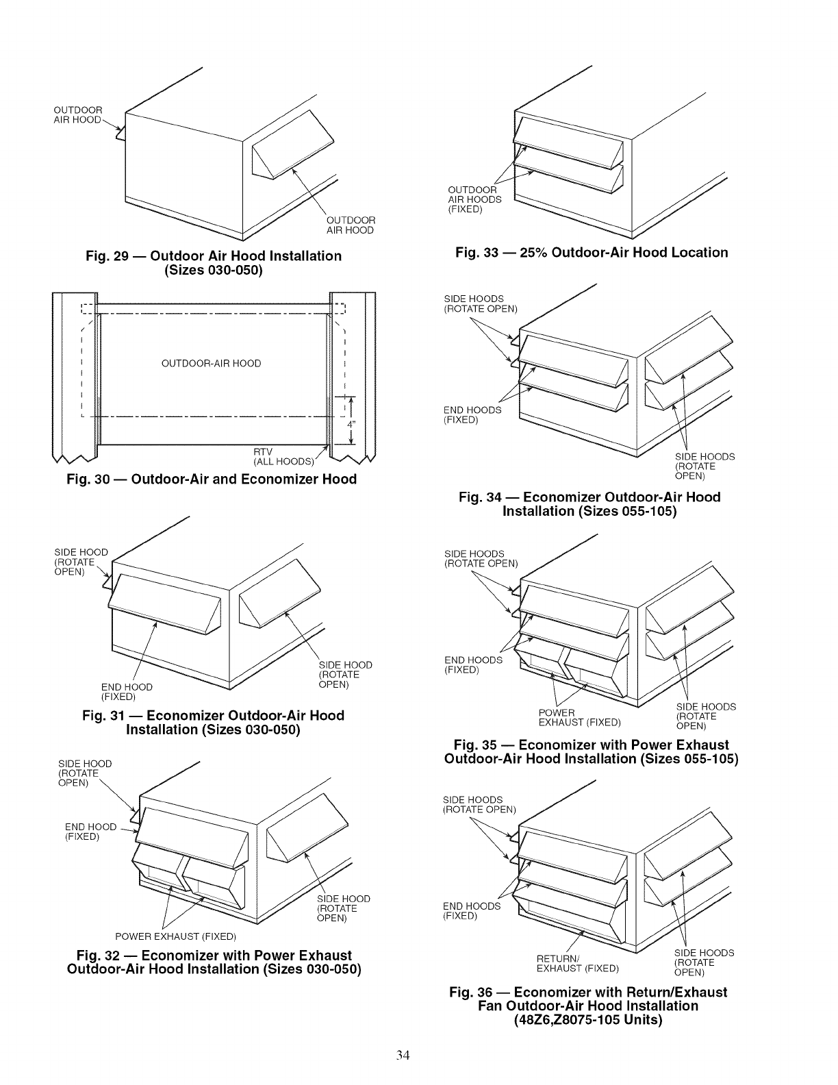
OUTDOOR
OUTDOOR
AIR HOOD
Fig. 29 -- Outdoor Air Hood Installation
(Sizes 030-050)
i--
i_
/
(
i
I
1
1
I
1
1
L _
OUTDOOR-AIRHOOD
==1
_ i
\
I
I
1
I
i
4"
__3_
RTV ,7
(ALL HOODS) _/
Fig. 30 -- Outdoor-Air and Economizer Hood
OUTDO0
AIRHOODS _
(FIXED) _
Fig. 33 -- 25% Outdoor-Air Hood Location
SIDE HOODS
(ROTATE OPEN)
END HOODS
(FIXED)
SIDE HOODS
(ROTATE
OPEN)
Fig. 34 -- Economizer Outdoor-Air Hood
Installation (Sizes 055-105)
SIDE HOOD
OPEN)
SIDE HOODS
(ROTATE OPEN)
SIDE HOOD
(ROTATE
END HOOD OPEN)
(FIXED)
Fig. 31 -- Economizer Outdoor-Air Hood
Installation (Sizes 030-050)
SIDE HOOD
(ROTATE
OPEN)
(FIXED)
END HOODS
(FIXED)
SIDE HOODS
POWER (ROTATE
EXHAUST (FIXED) OPEN)
Fig. 35 -- Economizer with Power Exhaust
Outdoor-Air Hood Installation (Sizes 055-105)
SIDE HOODS
(ROTATE OPEN)
SIDE HOOD
(ROTATE
OPEN)
POWER EXHAUST (FIXED)
Fig. 32 -- Economizer with Power Exhaust
Outdoor-Air Hood Installation (Sizes 030-050)
END HOODS
(FIXED)
SIDE HOODS
RETURN/ (ROTATE
EXHAUST (FIXED) OPEN)
Fig. 36 -- Economizer with Return/Exhaust
Fan Outdoor-Air Hood Installation
(48Z6,Z8075-105 Units)
34
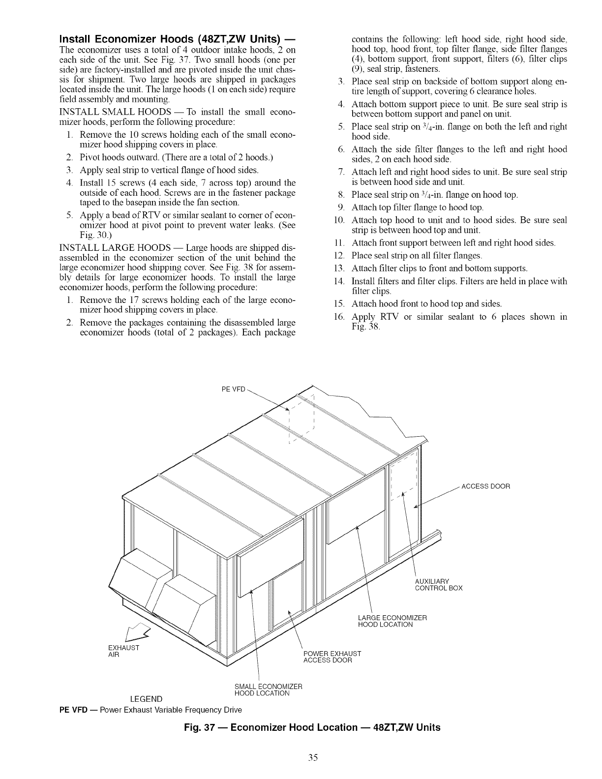
Install Economizer Hoods (48ZT, ZW Units) E
The economizer uses a total of 4 outdoor intake hoods, 2 on
each side of the unit. See Fig. 37. Two small hoods (one per
side) are factory-installed and are pivoted inside the unit chas-
sis for shipment. Two large hoods are shipped in packages
located inside the unit. The large hoods (1 on each side) require
field assembly and mounting.
INSTALL SMALL HOODS- To install the small econo-
mizer hoods, perform the following procedure:
1. Remove the 10 screws holding each of the small econo-
mizer hood shipping covers in place.
2. Pivot hoods outward. (There are a total of 2 hoods.)
3. Apply seal strip to vertical flange of hood sides.
4. Install 15 screws (4 each side, 7 across top) around the
outside of each hood. Screws are in the fastener package
taped to the basepan inside the fan section.
5. Apply a bead of RTV or shnilar sealant to corner of econ-
omizer hood at pivot point to prevent water leaks. (See
Fig. 30.)
INSTALL LARGE HOODS -- Large hoods are shipped dis-
assembled in the economizer section of the unit behind the
large economizer hood shipping cover. See Fig. 38 for assem-
bly details for large economizer hoods. To install the large
economizer hoods, perform the following procedure:
1. Remove the 17 screws holding each of the large econo-
mizer hood shipping covers in place.
2. Remove the packages containing the disassembled large
economizer hoods (total of 2 packages). Each package
contains the following: left hood side, right hood side,
hood top, hood front, top filter flange, side filter flanges
(4), bottom support, front support, filters (6), filter clips
(9), seal strip, fasteners.
3. Place seal strip on backside of bottom support along en-
tire length of support, covering 6 clearance holes.
4. Attach bottom support piece to unit. Be sure seal strip is
between bottom support and panel on unit.
5. Place seal strip on 3/4-in. flange on both the left and right
hood side.
6. Attach the side filter flanges to the left and right hood
sides, 2 on each hood side.
7. Attach left and right hood sides to unit. Be sure seal strip
is between hood side and unit.
8. Place seal strip on 3/4-in. flange on hood top.
9. Attach top filter flange to hood top.
10. Attach top hood to unit and to hood sides. Be sure seal
strip is between hood top and unit.
11. Attach front support between left and right hood sides.
12. Place seal strip on all filter flanges.
13. Attach filter clips to front and bottom supports.
14. Install filters and filter clips. Filters are held in place with
filter clips.
15. Attach hood front to hood top and sides.
16. Apply RTV or similar sealant to 6 places shown in
Fig. 38.
ACCESS DOOR
EXHAUST
AIR
AUXILIARY
CONTROLBOX
LARGE ECONOMIZER
HOOD LOCATION
POWER EXHAUST
ACCESS DOOR
SMALLECONOMIZER
HOODLOCATION
LEGEND
PE VFD -- Power Exhaust Variable Frequency Drive
Fig. 37 -- Economizer Hood Location -- 48ZT, ZW Units
35
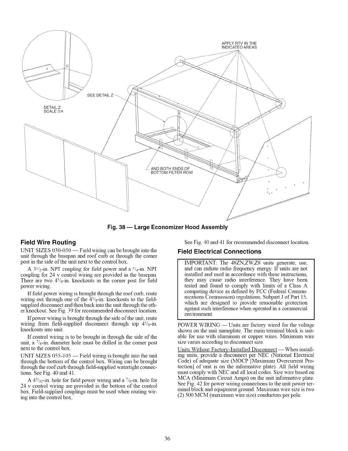
APPLY RTV IN THE
INDICATED AREAS
DETAIL Z
SCALE 3:4
SEE DETAIL Z
\\\\
AND BOTH ENDS OF
BOTTOM FILTER ROW
Fig. 38 -- Large Economizer Hood Assembly
Field Wire Routing
UNIT SIZES 030-050 -- Field wiring can be brought into the
unit through the basepan and roof curb or through the corner
post in the side of the unit next to the control box.
A 31/2-in. NPT coupling for field power and a 3/4-in. NPT
coupling for 24 v control wiring are provided in the basepan.
There are two 45/8-in. knockouts in the corner post for field
power wiring.
If field power wiring is brought through the roof curb, route
wiring out through one of the 45/8-in. knockouts to the field-
supplied disconnect and then back into the unit through the oth-
er knockout. See Fig. 39 for recolrnnended disconnect location.
If power wiring is brought through the side of the unit, route
wiring from field-supplied disconnect through top 45/s-in.
knockouts into unit.
If control wiring is to be brought in through the side of the
unit, a 7/s-in. diameter hole must be drilled in the corner post
next to the control box.
UNIT SIZES 055-105 -- Field wiring is brought into the unit
through the bottom of the control box. Wiring can be brought
through the roof curb through field-supplied watertight connec-
tions. See Fig. 40 and 41.
A 45/32-in. hole for field power wiring and a 7/s-in. hole for
24 v control wiring are provided in the bottom of the control
box. Field-supplied couplings must be used when routing wir-
ing into the control box.
See Fig. 40 and 41 for recolmnended disconnect location.
Field Electrical Connections
IMPORTANT: The 48ZN,ZW, Z8 units generate, use,
and can radiate radio frequency energy. If units are not
installed and used in accordance with these instructions,
they may cause radio interference. They have been
tested and found to comply with limits of a Class A
computing device as defined by FCC (Federal Cogunu-
nications Colrnnission) regulations, Subpart J of Part 15,
which are designed to provide reasonable protection
against such interference when operated in a cogunercial
enviromnent.
POWER WIRING -- Units are factory wired for the voltage
shown on the unit nameplate. The main terminal block is suit-
able for use with aluminum or copper wires. Maximum wire
size varies according to disconnect size.
Units Without Factory-Installed Disconnect -- When install-
ing units, provide a disconnect per NEC (National Electrical
Code) of adequate size (MOCP [Maxhnum Overcurrent Pro-
tection] of unit is on the informative plate). All field wiring
must comply with NEC and all local codes. Size wire based on
MCA (Minimum Circuit Amps) on the unit informative plate.
See Fig. 42 for power wiring connections to the unit power ter-
minal block and equipment ground. Maximum wire size is two
(2) 500 MCM (maximum wire size) conductors per pole.
36
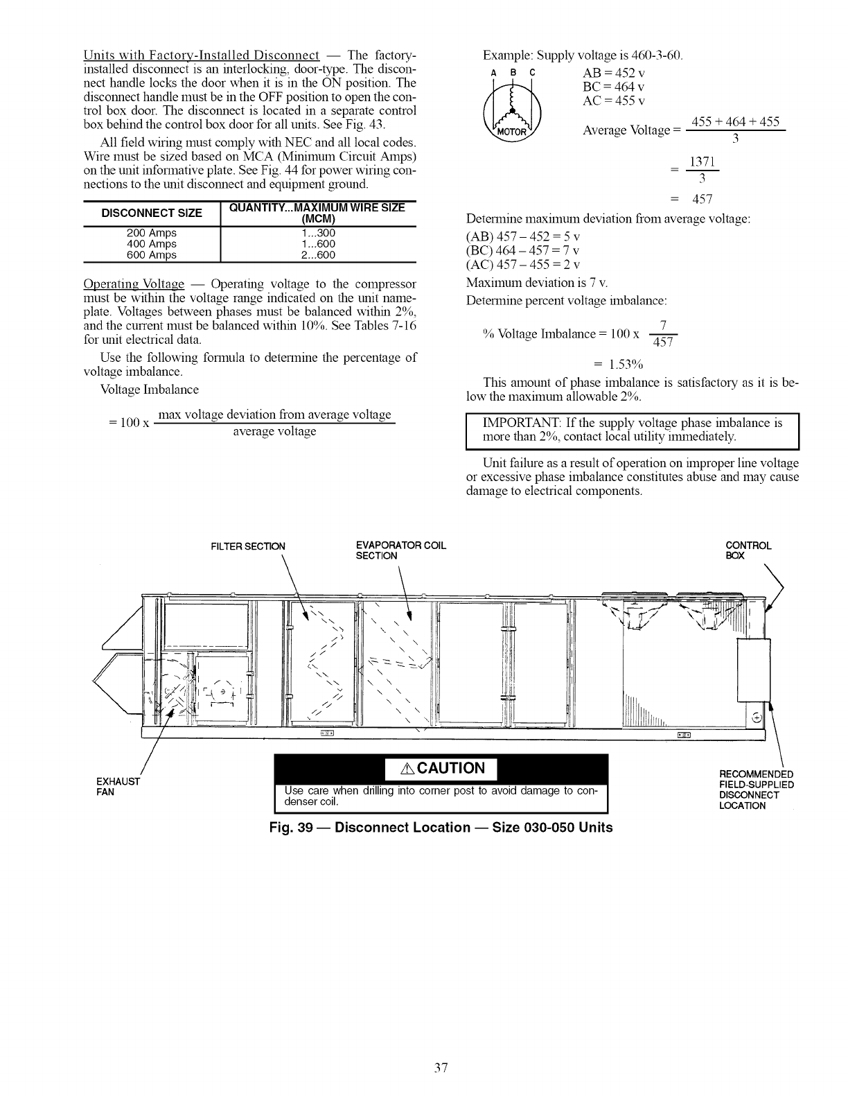
Units with Factory-Installed Disconnect -- The factory-
installed disconnect is an interlocking, door-type. The discon-
nect handle locks the door when it is in the ON position. The
disconnect handle must be in the OFF position to open the con-
trol box door. The disconnect is located in a separate control
box behind the control box door for all units. See Fig. 43.
All field wiring must comply with NEC and all local codes.
Wire must be sized based on MCA (Minimum Circuit Amps)
on the unit informative plate. See Fig. 44 for power wiring con-
nections to the unit disconnect and equipment ground.
DISCONNECT SIZE QUANTITY...MAXIMUM WIRE SIZE
(MCM)
200 Amps 1 ,,,300
400 Amps 1 ,,,600
600 Amps 2,,,600
Operating Voltage -- Operating voltage to the compressor
must be within the voltage range indicated on the unit name-
plate. Voltages between phases must be balanced within 2%,
and the current must be balanced within 10%. See Tables 7-16
for unit electrical data.
Use the following formula to determine the percentage of
voltage imbalance.
Voltage hnbalance
= 100 x max voltage deviation from average voltage
average voltage
Example: Supply voltage is 460-3-60.
A B C AB = 452 v
BC = 464 v
AC = 455 v
Average Voltage = 455 + 464 + 455
3
1371
3
= 457
Determine maximum deviation from average voltage:
(AB) 457 - 452 = 5 v
(BC) 464 - 457 = 7 v
(AC) 457 - 455 = 2 v
Maximum deviation is 7 v.
Determine percent voltage hnbalance:
7
% Voltage Imbalance = 100 x 45----5-
= 1.53%
This amount of phase imbalance is satisfactory as it is be-
low the maximum allowable 2%.
I IMPORTANT: If the supply voltage phase hnbalance is I
more than 2%, contact local utility ilmnediately. I
Unit failure as a result of operation on hnproper line voltage
or excessive phase imbalance constitutes abuse and may cause
damage to electrical components.
EXHAUST
FAN
/
FILTER SECTION EVAPORATOR COIL
SECTION
7/ \\
\--
\\ \
\\ N, \
\ \
/./'
/-.... \ \
// \ \
t_
Use care when drilling into corner post to avoid damage to con-
denser coil,
CONTROL
BOX
cYlfl!
I
RECOMMENDED
FIELD-SUPPLIED
DISCONNECT
LOCATION
Fig. 39 -- Disconnect Location -- Size 030-050 Units
37
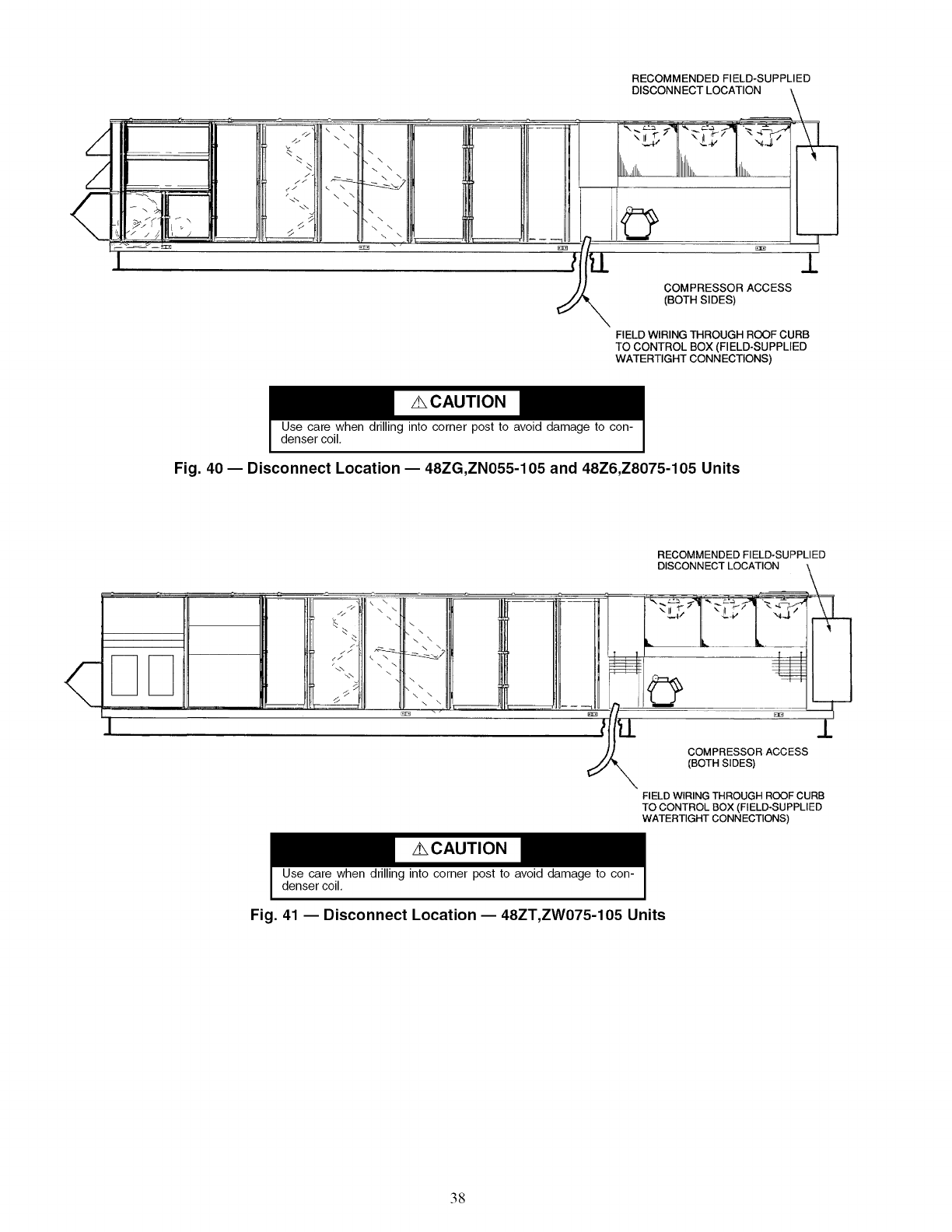
RECOMMENDED FIELD-SUPPLIED
ii /..
\
COMPRESSOR ACCESS
(BOTH SIDES)
FIELD WIRING THROUGH ROOF CURB
TO CONTROL BOX (FIELD-SUPPLIED
WATERTIGHT CONNECTIONS)
Use care when drilling into corner post to avoid damage to con-
denser coil,
Fig. 40- Disconnect Location -- 48ZG,ZN055-105 and 48Z6,Z8075-105 Units
RECOMMENDED FIELD-SUPPLIED
DISCONNECT LOCATION
COMPRESSOR ACCESS
(BOTH SIDES)
FIELD WIRING THROUGH ROOF CURB
TO CONTROL BOX (FIELD-SUPPLIED
WATERTIGHT CONNECTIONS)
Use care when drilling into corner post to avoid damage to con-
denser coil,
Fig. 41 -- Disconnect Location -- 48ZT,ZW075-105 Units
38
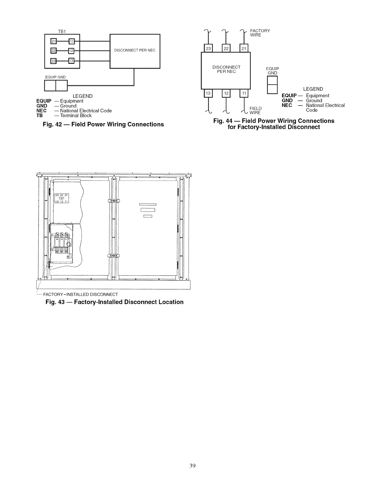
TB1
EF-----EH DISCONNECT PER NEC
EQUIP GND
LEGEND
EQUIP --Equipment
GND -- G round
NEC --National Electrical Code
TB --Terminal Block
Fig. 42 -- Field Power Wiring Connections
DISCONNECT
PER NEC
FACTORY
WIRE
EQUIP
GND
B
I?=FIEL D
L, WIRE
LEGEND
EQUIP-- Equipment
GND -- Ground
NEC -- National Electrical
Code
Fig. 44 -- Field Power Wiring Connections
for Factory-Installed Disconnect
FACTORY-INSTALLED DISCONNECT
Fig. 43 -- Factory-Installed Disconnect Location
39
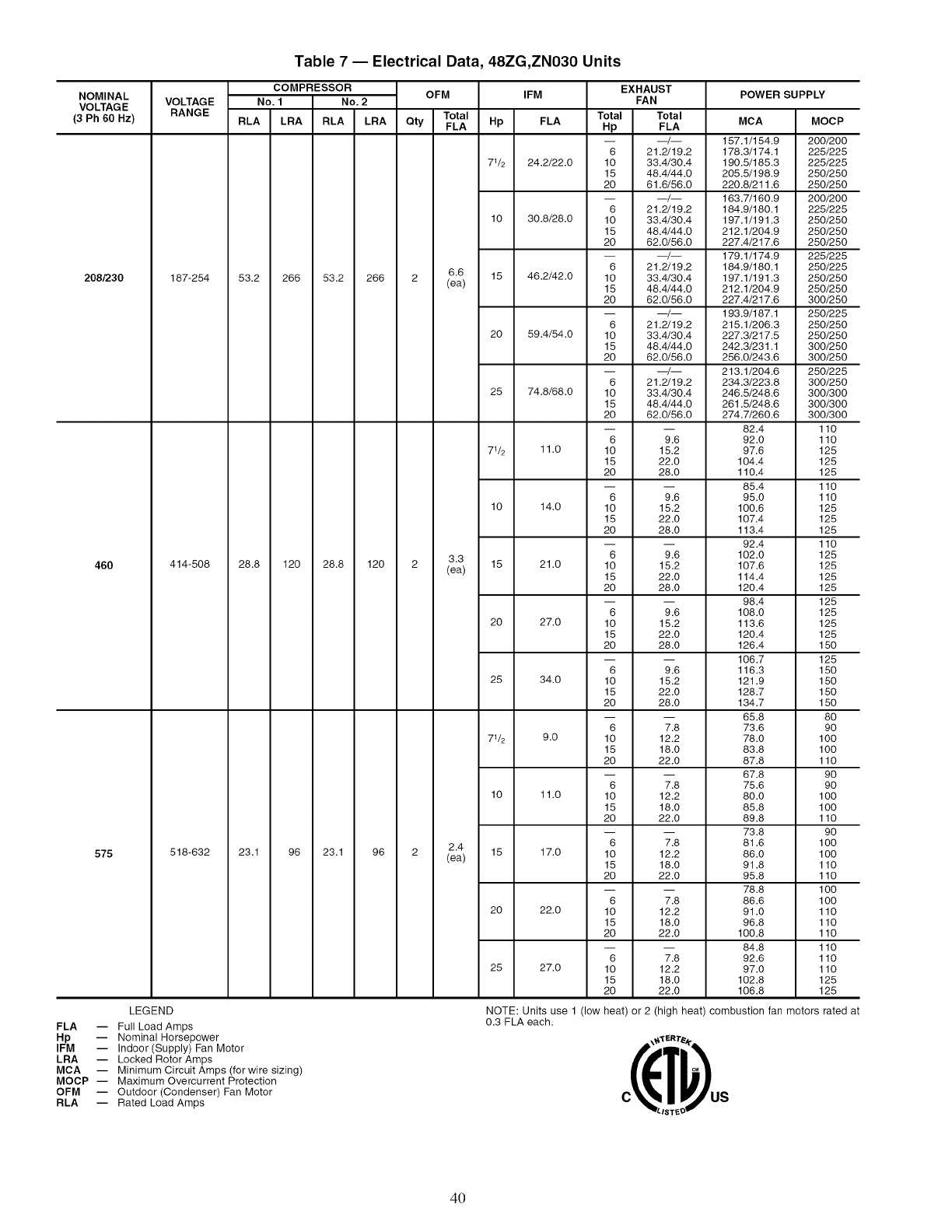
NOMINAL
VOLTAGE
(3 Ph 60 Hz)
208/230
46O
575
FLA --
Hp
IFM --
LRA --
MCA --
MOCP --
OFM --
RLA --
Table 7 -- Electrical Data, 48ZG,ZN030 Units
COMPRESSOR OFM IFM
VOLTAGE No. 1 No. 2
RANGE Total
RLA LRA RLA LRA Qty FLA Hp FLA
71/2 24.2/22.0
10 30.8/28.0
6.6 15 46.2/42.0
187-254 53.2 266 53.2 266 2 (ea)
20 59.4/54.0
25 74.8/68.0
71/2 11.0
10 14.0
3.3 15 21.0
414-508 28.8 120 28.8 120 2 (ea)
20 27.0
25 34.0
71/2 9.0
10 11.0
2.4 15 17.0
518-632 23.1 96 23.1 96 2 (ea)
20 22.0
25 27.0
EXHAUST
FAN
Total Total
Hp FLA
-- __/__
6 21.2/19.2
10 33.4/30.4
15 48.4/44.0
20 61.6/56.0
-- __/__
6 21.2/19.2
10 33.4/30.4
15 48.4/44.0
20 62.0/56.0
-- __/__
6 21.2/19.2
10 33.4/30.4
15 48.4/44.0
20 62.0/56.0
-- __/__
6 21.2/19.2
10 33.4/30.4
15 48.4/44.0
20 62.0/56.0
-- __/__
6 21.2/19.2
10 33.4/30.4
15 48.4/44.0
20 62.0/56.0
6 9.6
10 15.2
15 22.0
20 28.0
6 9.6
10 15.2
15 22.0
20 28.0
6 9.6
10 15.2
15 22.0
20 28.0
6 9.6
10 15.2
15 22.0
20 28.0
6 9.6
10 15.2
15 22.0
20 28.0
6 7.8
10 12.2
15 18.0
20 22.0
6 7.8
10 12.2
15 18.0
20 22.0
6 7.8
10 12.2
15 18.0
20 22.0
6 7.8
10 12.2
15 18.0
20 22.0
6 7.8
10 12.2
15 18.0
20 22.0
POWER SUPPLY
MCA MOCP
157.1/154.9 200/200
178.3/174.1 225/225
190.5/185.3 225/225
205.5/198.9 250/250
220.8/211.6 250/250
163.7/160.9 200/200
184.9/180.1 225/225
197.1/191.3 250/250
212.1/204.9 250/250
227.4/217.6 250/250
179.1/174.9 225/225
184.9/180.1 250/225
197.1/191.3 250/250
212.1/204.9 250/250
227.4/217.6 300/250
193.9/187.1 250/225
215.1/206.3 250/250
227.3/217.5 250/250
242.3/231.1 300/250
256.0/243.6 300/250
213.1/204.6 250/225
234.3/223.8 300/250
246.5/248.6 300/300
261.5/248.6 300/300
274.7/260.6 300/300
82.4 110
92.0 110
97.6 125
104.4 125
110.4 125
85.4 110
95.0 110
100.6 125
107.4 125
113.4 125
92.4 110
102.0 125
107.6 125
114.4 125
120.4 125
98.4 125
108.0 125
113.6 125
120.4 125
126.4 150
106.7 125
116.3 150
121.9 150
128.7 150
134.7 150
65.8 80
73.6 90
78.0 100
83.8 100
87.8 110
67.8 90
75.6 90
80.0 1O0
85.8 1O0
89.8 110
73.8 90
81.6 100
86.0 100
91.8 110
95.8 110
78.8 1O0
86.6 1O0
91.0 110
96.8 110
100.8 110
84.8 110
92.6 110
97.0 110
102.8 125
106.8 125
LEGEND
Full Load Amps
Nominal Horsepower
Indoor (Supply) Fan Motor
Locked Rotor Amps
Minimum Circuit Amps (for wire sizing)
Maximum Overcurrent Protection
Outdoor (Condenser) Fan Motor
Rated Load Amps
NOTE: Units use 1 (low
0.3 FLA each. heat) or 2 (high heat) combustion fan motors rated at
ISTE
40
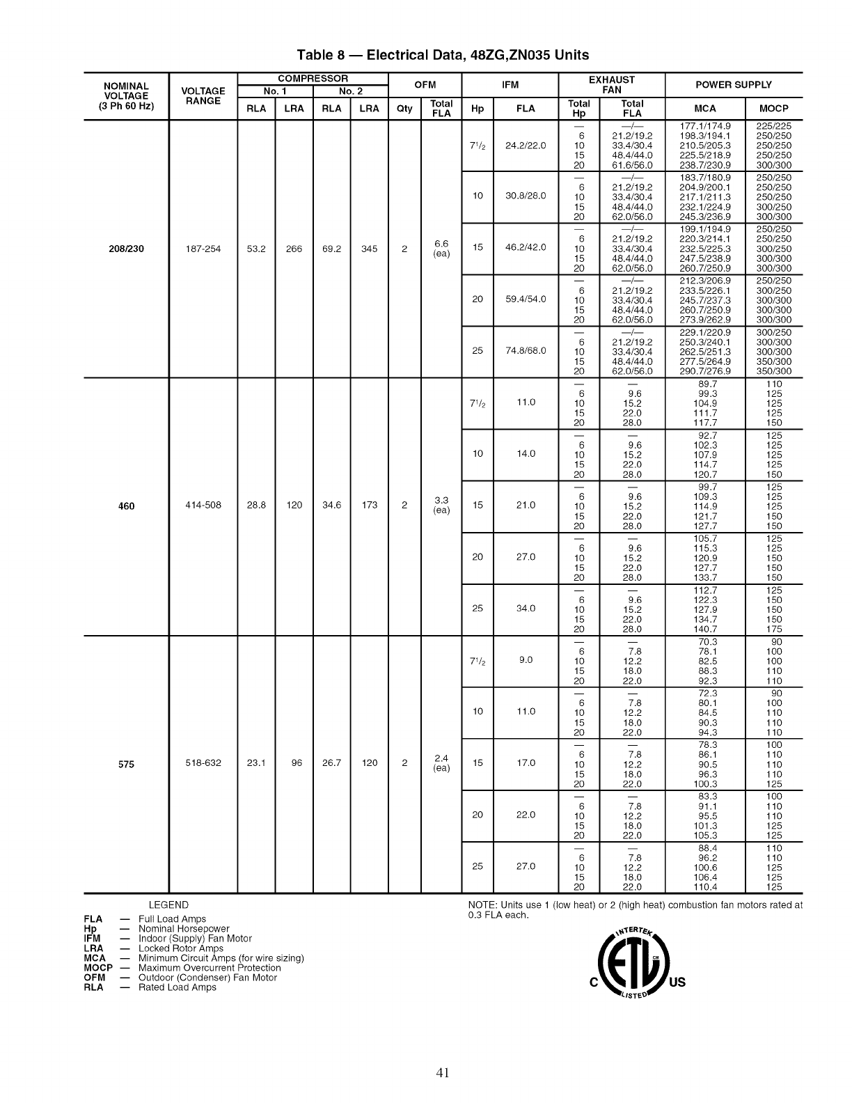
Table 8 -- Electrical Data, 48ZG,ZN035 Units
NOMINAL
VOLTAGE
(3 Ph 60 Hz)
208/230
460
575
COMPRESSOR OFM IFM
VOLTAGE No. 1 No. 2
RANGE Total
RLA LRA RLA LRA Qty FLA Hp FLA
71/2 24.2/22.0
10 30.8/28.0
6.6 15 46.2/42.0
187-254 53.2 266 69.2 345 2 (ea)
20 59.4/54.0
25 74.8/68.0
71/2 11.0
10 14.0
3.3 15 21.0
414-508 28.8 120 34.6 173 2 (ea)
20 27.0
25 34.0
71/2 9.0
10 11.0
2.4 15 17.0
518-632 23.1 96 26.7 120 2 (ea)
20 22.0
25 27.0
EXHAUST
FAN
Total Total
Hp FLA
6 21.2/19.2
10 33.4/30.4
15 48.4/44.0
20 61.6/56.0
6 21.2/19.2
10 33.4/30.4
15 48.4/44.0
20 62.0/56.0
6 21.2/19.2
10 33.4/30.4
15 48.4/44.0
20 62.0/56.0
6 21.2/19.2
10 33.4/30.4
15 48.4/44.0
20 62.0/56.0
6 21.2/19.2
10 33.4/30.4
15 48.4/44.0
20 62.0/56.0
6 9.6
10 15.2
15 22.0
20 28.0
6 9.6
10 15.2
15 22.0
20 28.0
6 9.6
10 15.2
15 22.0
20 28.0
6 9.6
10 15.2
15 22.0
20 28.0
6 9.6
10 15.2
15 22.0
20 28.0
6 7.8
10 12.2
15 18.0
20 22.0
6 7.8
10 12.2
15 18.0
20 22.0
6 7.8
10 12.2
15 18.0
20 22.0
6 7.8
10 12.2
15 18.0
20 22.0
6 7.8
10 12.2
15 18.0
20 22.0
POWER SUPPLY
MCA MOCP
177.1/174.9 225/225
198.3/194.1 250/250
210.5/205.3 250/250
225.5/218.9 250/250
238.7/230.9 300/300
183.7/180.9 250/250
204.9/200.1 250/250
217.1/211.3 250/250
232.1/224.9 300/250
245.3/236.9 300/300
199.1/194.9 250/250
220.3/214.1 250/250
232.5/225.3 300/250
247.5/238.9 300/300
260.7/250.9 300/300
212.3/206.9 250/250
233.5/226.1 300/250
245.7/237.3 300/300
260.7/250.9 300/300
273.9/262.9 300/300
229.1/220.9 300/250
250.3/240.1 300/300
262.5/251.3 300/300
277.5/264.9 350/300
290.7/276.9 350/300
89.7 110
99.3 125
104.9 125
111.7 125
117.7 150
92.7 125
102.3 125
107.9 125
114.7 125
120.7 150
99.7 125
109.3 125
114.9 125
121.7 150
127.7 150
105.7 125
115.3 125
120.9 150
127.7 150
133.7 150
112.7 125
122.3 150
127.9 150
134.7 150
140.7 175
70.3 90
78.1 100
82.5 100
88.3 110
92.3 110
72.3 90
80.1 100
84.5 110
90.3 110
94.3 110
78.3 100
86.1 110
90.5 110
96.3 110
100.3 125
83.3 100
91.1 110
95.5 110
101.3 125
105.3 125
88.4 110
96.2 110
100.6 125
106.4 125
110.4 125
LEGEND
FLA -- Full Load Amps
Hp -- Nominal Horsepower
IFM -- Indoor (Supply) Fan Motor
LRA -- Locked Rotor Amps
MCA -- Minimum Circuit Amps (for wire sizing)
MOCP -- Maximum Overcurrent Protection
OFM -- Outdoor (Condenser) Fan Motor
RLA -- Rated Load Amps
NOTE: Units use 1 (low heat) or 2 (high heat) combustion
0.3 FLA each.
/ST_
fan motors rated at
4!
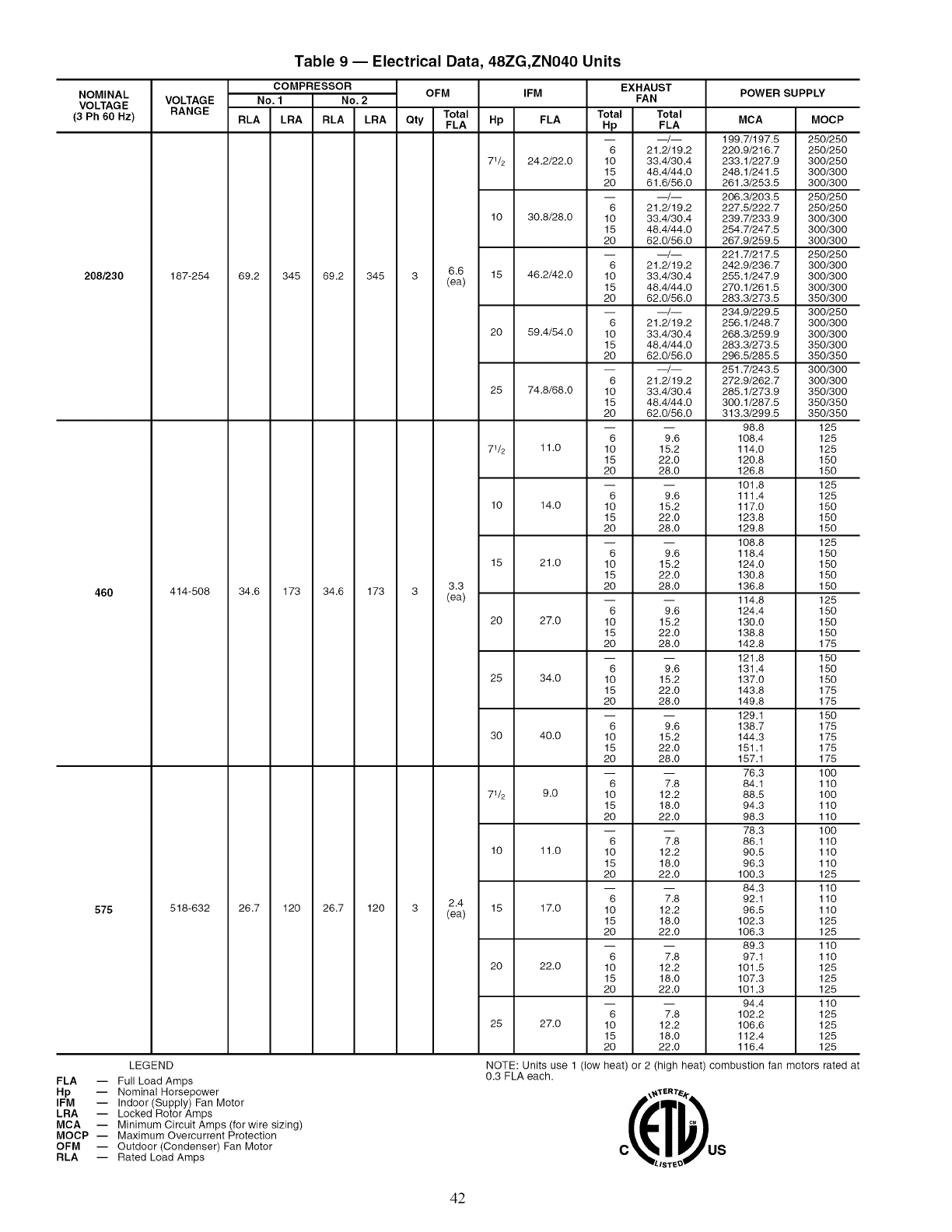
NOMINAL
VOLTAGE
(3 Ph 60 Hz)
208/230
46O
575
FLA --
Hp
IFM --
LRA --
MCA --
MOCP --
OFM --
RLA --
Table 9 -- Electrical Data, 48ZG,ZN040 Units
COMPRESSOR OFM
VOLTAGE No. 1 No. 2
RANGE Total
RLA LRA RLA LRA Qty FLA
6.6
187-254 69.2 345 69.2 345 3 (ea)
3.3
414-508 34.6 173 34.6 173 3 (ea)
2.4
518-632 26.7 120 26.7 120 3 (ea)
LEGEND
Full Load Amps
Nominal Horsepower
Indoor (Supply) Fan Motor
Locked Rotor Amps
Minimum Circuit Amps (for wire sizing)
Maximum Overcurrent Protection
Outdoor (Condenser) Fan Motor
Rated Load Amps
IFM
Hp FLA
71/2 24.2/22.0
10 30.8/28.0
15 46.2/42.0
20 59.4/54.0
25 74.8/68.0
71/2 11.0
10 14.0
15 21.0
20 27.0
25 34.0
30 40.0
71/2 9.0
10 11.0
15 17.0
20 22.0
25 27.0
NOTE: Units use 1 (low
0.3 FLA each.
EXHAUST
FAN
Total Total
Hp FLA
-- __/__
6 21.2/19.2
10 33.4/30.4
15 48.4/44.0
20 61.6/56.0
-- __/__
6 21.2/19.2
10 33.4/30.4
15 48.4/44.0
20 62.0/56.0
-- __/__
6 21.2/19.2
10 33.4/30.4
15 48.4/44.0
20 62.0/56.0
-- __/__
6 21.2/19.2
10 33.4/30.4
15 48.4/44.0
20 62.0/56.0
-- __/__
6 21.2/19.2
10 33.4/30.4
15 48.4/44.0
20 62.0/56.0
6 9.6
10 15.2
15 22.0
20 28.0
6 9.6
10 15.2
15 22.0
20 28.0
6 9.6
10 15.2
15 22.0
20 28.0
6 9.6
10 15.2
15 22.0
20 28.0
6 9.6
10 15.2
15 22.0
20 28.0
6 9.6
10 15.2
15 22.0
20 28.0
6 7.8
10 12.2
15 18.0
20 22.0
6 7.8
10 12.2
15 18.0
20 22.0
6 7.8
10 12.2
15 18.0
20 22.0
6 7.8
10 12.2
15 18.0
20 22.0
6 7.8
10 12.2
15 18.0
20 22.0
heat) or 2 (high
POWER SUPPLY
MCA
199.7/197.5
220.9/216.7
233.1/227.9
248.1/241.5
261.3/253.5
206.3/203.5
227.5/222.7
239.7/233.9
254.7/247.5
267.9/259.5
221.7/217.5
242.9/236.7
255.1/247.9
270.1/261.5
283.3/273.5
234.9/229.5
256.1/248.7
268.3/259.9
283.3/273.5
296.5/285.5
251.7/243.5
272.9/262.7
285.1/273.9
300.1/287.5
313.3/299.5
98.8
108.4
114.0
120.8
126.8
101.8
111.4
117.0
123.8
129.8
108.8
118.4
124.0
130.8
136.8
114.8
124.4
130.0
138.8
142.8
121.8
131.4
137.0
143.8
149.8
129.1
138.7
144.3
151.1
157.1
76.3
84.1
88.5
94.3
98.3
78.3
86.1
90.5
96.3
100.3
84.3
92.1
96.5
102.3
106.3
89.3
97.1
101.5
107.3
101.3
94.4
102.2
106.6
112.4
116.4
heat) combustion
MOCP
250/250
250/250
300/250
300/300
300/300
250/250
250/250
300/300
300/300
300/300
250/250
300/300
300/300
300/300
350/300
300/250
300/300
300/300
350/300
350/350
300/300
300/300
350/300
350/350
350/350
125
125
125
150
150
125
125
150
150
150
125
150
150
150
150
125
150
150
150
175
150
150
150
175
175
150
175
175
175
175
100
110
100
110
110
100
110
110
110
125
110
110
110
125
125
110
110
125
125
125
110
125
125
125
125
fan motors rated at
c¢T o
/-IST_O
42
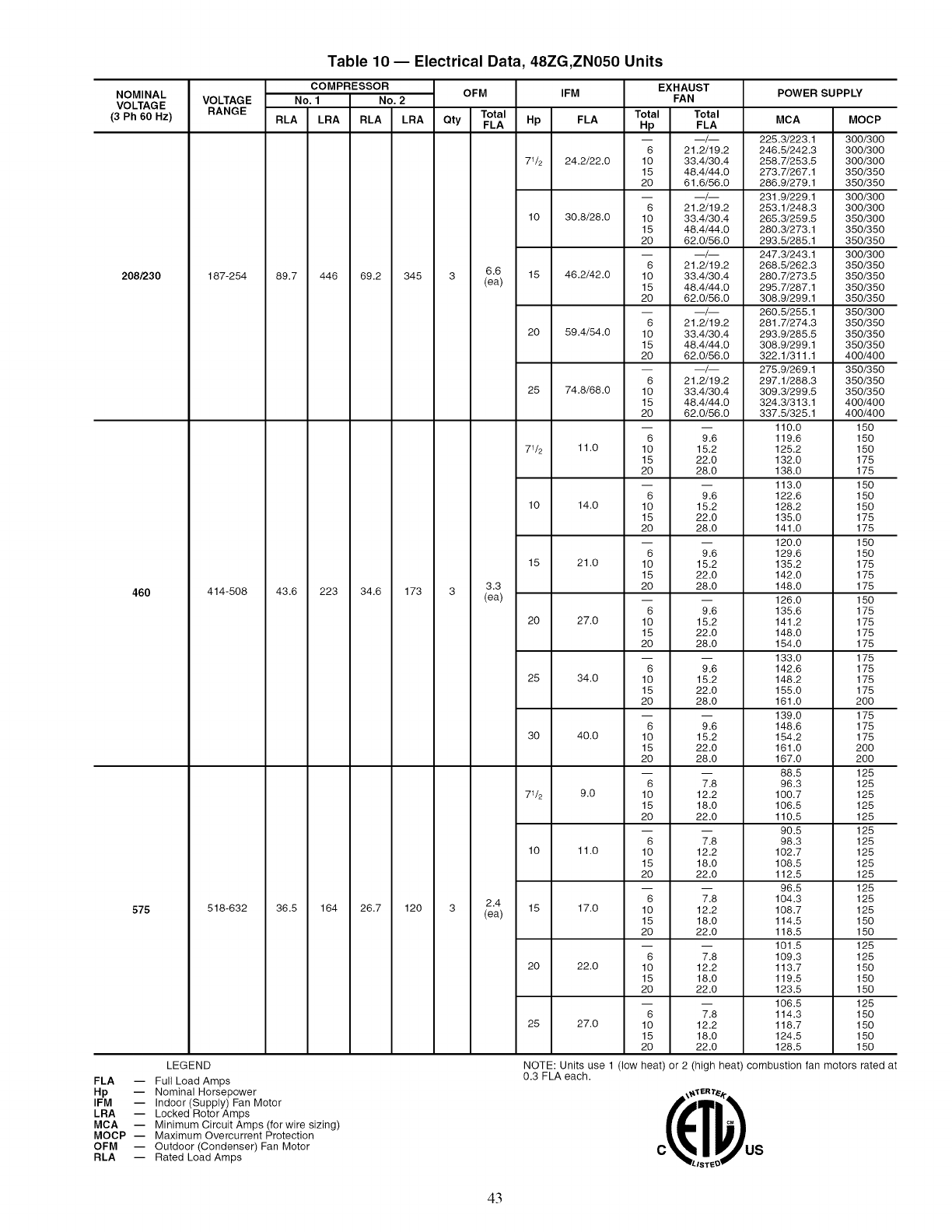
Table 10- Electrical Data, 48ZG,ZN050 Units
NOMINAL
VOLTAGE
(3 Ph 60 Hz)
208/230
460
575
COMPRESSOR OFM
VOLTAGE No. 1 No. 2
RANGE Total
RLA LRA RLA LRA Qty FLA
187-254 89.7 446 69.2 345
414-508 43.6 223 34.6 173
518-632 36.5 164 26.7 120
LEGEND
FLA -- Full Load Amps
Hp -- Nominal Horsepower
IFM -- Indoor (Supply) Fan Motor
LRA -- Locked Rotor Amps
MCA -- Minimum Circuit Amps (for wire sizing)
MOCP -- Maximum Overcurrent Protection
OFM -- Outdoor (Condenser) Fan Motor
RLA -- Rated Load Amps
EXHAUST
IFM FAN
Total Total
Hp FLA Hp FLA
6 21.2/19.2
71/2 24.2/22.0 10 33.4/30.4
15 48.4/44.0
20 61.6/56.0
6 21.2/19.2
10 30.8/28.0 10 33.4/30.4
15 48.4/44.0
20 62.0/56.0
6 21.2/19.2
6.6 15 46.2/42.0 10 33.4/30.4
3 (ea) 15 48.4/44.0
20 62.0/56.0
6 21.2/19.2
20 59.4/54.0 10 33.4/30.4
15 48.4/44.0
20 62.0/56.0
6 21.2/19.2
25 74.8/68.0 10 33.4/30.4
15 48.4/44.0
20 62.0/56.0
6 9.6
71/2 11.0 10 15.2
15 22.0
20 28.0
6 9.6
10 14.0 10 15.2
15 22.0
20 28.0
6 9.6
15 21.0 10 15.2
15 22.0
3.3 20 28.0
3 (ea) _ _
6 9.6
20 27.0 10 15.2
15 22.0
20 28.0
6 9.6
25 34.0 10 15.2
15 22.0
20 28.0
6 9.6
30 40.0 10 15.2
15 22.0
20 28.0
6 7.8
71/2 9.0 10 12.2
15 18.0
20 22.0
6 7.8
10 11.0 10 12.2
15 18.0
20 22.0
2.4 6 7.8
3 (ea) 15 17.0 10 12.2
15 18.0
20 22.0
6 7.8
20 22.0 10 12.2
15 18.0
20 22.0
6 7.8
25 27.0 10 12.2
15 18.0
20 22.0
POWER SUPPLY
MCA MOCP
225.3/223.1 300_00
246.5/242.3 300_00
258.7/253.5 300_00
273.7/267.1 350_50
286.9_79.1 350_50
231.9_29.1 300_00
253.1_48.3 300_00
265.3/259.5 350_00
280.3/273.1 350_50
293.5/285.1 350_50
247.3/243.1 300_00
268.5/262.3 350_50
280.7/273.5 350_50
295.7/287.1 350_50
308.9_99.1 350_50
260.5/255.1 350_00
281.7/274.3 350_50
293.9_85.5 350_50
308.9_99.1 350_50
322.1/311.1 400_00
275.9_69.1 350_50
297.1_88.3 350_50
309.3/299.5 350_50
324._313.1 400_00
337._325.1 400_00
110.0 150
119.6 150
125.2 150
132.0 175
138.0 175
113.0 150
122.6 150
128.2 150
135.0 175
141.0 175
120.0 150
129.6 150
135.2 175
142.0 175
148.0 175
126.0 150
135.6 175
141.2 175
148.0 175
154.0 175
133.0 175
142.6 175
148.2 175
155.0 175
161.0 200
139.0 175
148.6 175
154.2 175
161.0 200
167.0 200
88.5 125
96.3 125
100.7 125
106.5 125
110.5 125
90.5 125
98.3 125
102.7 125
108.5 125
112.5 125
96.5 125
104.3 125
108.7 125
114.5 150
118.5 150
101.5 125
109.3 125
113.7 150
119.5 150
123.5 150
106.5 125
114.3 150
118.7 150
124.5 150
128.5 150
NOTE: Units use 1 (low heat) or 2 (high heat) combustion
0.3 FLA each.
\_'1 ER T_'/r
/-IST_..D
fan motors rated at
43

Table 11 -- Electrical Data, 48ZG,ZN055 Units
NOMINAL
VOLTAGE
(3 Ph 60 Hz)
208/230
460
575
COMPR COMPR OFM IFM
VOLTAGE NO. 1 NO. 2
RANGE RLA LRA RLA LRA Total Hp FLA
FLA
15 46.2/42
20 59.4/54
187-254 108 506 74.4 345 26.4 25 74.8/68
30 88.0/80
40 114.4/104
15 21.0
20 27.0
414-508 50.6 253 34.6 173 13.2 25 34.0
30 40.0
40 52.0
15 17.0
20 22.0
518-632 39.1 176 28.8 120 9.6 25 27.0
LEGEND
FLA -- Full Load Amps
Hp -- Nominal Horsepower
IFM -- Indoor (Supply) Fan Motor
LRA -- Locked Rotor Amps
MCA -- Minimum Circuit Amps (for wire sizing)
MOCP-- Maximum Overcurrent Protection
OFM -- Outdoor (Condenser) Fan Motor
RLA -- Rated Load Amps
30 32.0
40 41.0
BASE UNIT EXHAUST
ONLY FAN
MCA MOCP Total Total MCA
Hp FLA
10 34/30 315.0/307.4
281.6/277.4 350/350 15 48/44 330.0/321.4
20 62/56 343.2/333.4
10 34/30 328.2/319.4
294.8/289.4 400/350 15 48/44 343.2/333.4
20 62/56 356.4/345.4
10 34/30 343.6/333.4
310.2/303.4 400/400 15 48/44 358.6/347.4
20 62/56 371.8/359.4
10 34/30 356.8/345.4
323.4/315.4 400/400 15 48/44 371.8/359.4
20 62/56 385.0/371.4
10 34/30 384.9/369.8
351.5/339.4 450/400 15 48/44 399.9/383.4
20 62/56 412.6/395.4
10 15.2 147.3
132.1 175 15 22.0 154.1
20 28.0 160.1
10 15.2 153.3
138.1 175 15 22.0 160.1
20 28.0 166.1
10 15.2 160.3
145.1 175 15 22.0 167.1
20 28.0 173.1
10 15.2 166.3
151.1 200 15 22.0 173.1
20 28.0 179.1
10 15.2 178.6
163.4 200 15 22.0 185.4
20 28.0 191.4
10 12.2 116.5
104.3 125 15 18.0 122.3
20 22.0 126.3
10 12.2 121.5
109.3 125 15 18.0 127.3
20 22.0 131.3
10 12.2 126.5
114.3 150 15 18.0 132.3
20 22.0 136.3
10 12.2 131.5
119.3 150 15 18.0 137.3
20 22.0 141.3
10 12.2 141.0
128.8 150 15 18.0 146.8
20 22.0 150.8
BASE UNIT WITH
EXHAUST FAN
MOCP
400/400
400/400
450/400
400/400
450/400
450/450
450/400
450/450
450/450
450/450
450/450
450/450
450/450
500/450
500/500
175
200
200
200
200
200
200
200
200
200
200
225
225
225
225
150
150
150
150
150
150
150
150
175
150
175
175
175
175
175
NOTE: Units use 2 (low heat) or 3 (high heat) combustion fan
motors rated at 0.3 FLA each.
/*IST_D
44
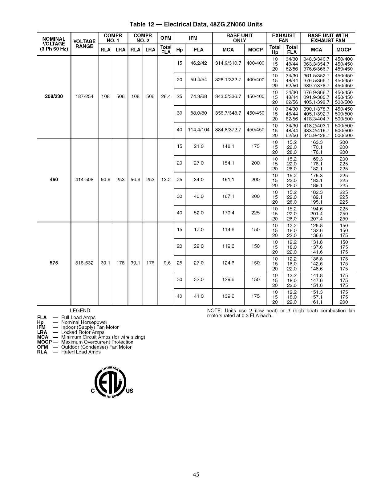
Table 12- Electrical Data, 48ZG,ZN060 Units
NOMINAL
VOLTAGE
(3 Ph 60 Hz)
208/230
460
575
COMPR COMPR OFM IFM
VOLTAGE NO. 1 NO. 2
RANGE RLA LRA RLA LRA Total Hp FLA
FLA
15 46.2/42
20 59.4/54
187-254 108 506 108 506 26.4 25 74.8/68
30 88.0/80
40 114.4/104
15 21.0
20 27.0
414-508 50.6 253 50.6 253 13.2 25 34.0
30 40.0
40 52.0
15 17.0
20 22.0
518-632 39.1 176 39.1 176 9.6 25 27.0
LEGEND
FLA -- Full Load Amps
Hp -- Nominal Horsepower
IFM -- Indoor (Supply) Fan Motor
LRA -- Locked Rotor Amps
MCA -- Minimum Circuit Amps (for wire sizing)
MOCP-- Maximum Overcurrent Protection
OFM -- Outdoor (Condenser) Fan Motor
RLA -- Rated Load Amps
30 32.0
40 41.0
BASE UNIT EXHAUST
ONLY FAN
MCA MOCP Total Total MCA
Hp FLA
10 34/30 348.3/340.7
314.9/310.7 400/400 15 48/44 363.3/354.7
20 62/56 376.6/366.7
10 34/30 361.5/352.7
328.1/322.7 400/400 15 48/44 376.5/366.7
20 62/56 389.7/378.7
10 34/30 376.9/366.7
343.5/336.7 450/400 15 48/44 391.9/380.7
20 62/56 405.1/392.7
10 34/30 390.1/378.7
356.7/348.7 450/450 15 48/44 405.1/392.7
20 62/56 418.3/404.7
10 34/30 418.2/403.1
384.8/372.7 450/450 15 48/44 433.2/416.7
20 62/56 445.9/428.7
10 15.2 163.3
148.1 175 15 22.0 170.1
20 28.0 176.1
10 15.2 169.3
154.1 200 15 22.0 176.1
20 28.0 182.1
10 15.2 176.3
161.1 200 15 22.0 183.1
20 28.0 189.1
10 15.2 182.3
167.1 200 15 22.0 189.1
20 28.0 195.1
10 15.2 194.6
179.4 225 15 22.0 201.4
20 28.0 207.4
10 12.2 126.8
114.6 150 15 18.0 132.6
20 22.0 136.6
10 12.2 131.8
119.6 150 15 18.0 137.6
20 22.0 141.6
10 12.2 136.8
124.6 150 15 18.0 142.6
20 22.0 146.6
10 12.2 141.8
129.6 150 15 18.0 147.6
20 22.0 151.6
10 12.2 151.3
139.6 175 15 18.0 157.1
20 22.0 161.1
BASE UNIT WITH
EXHAUST FAN
MOCP
450/400
450/450
450/450
450/450
450/450
450/450
450/450
450/450
500/500
450/450
500/500
500/500
500/500
500/500
500/500
200
200
200
200
225
225
225
225
225
225
225
225
225
250
250
150
150
175
150
175
175
175
175
175
175
175
175
175
175
200
NOTE: Units use 2 (low heat) or 3 (high heat) combustion fan
motors rated at 0.3 FLA each.
/-IST_D
45
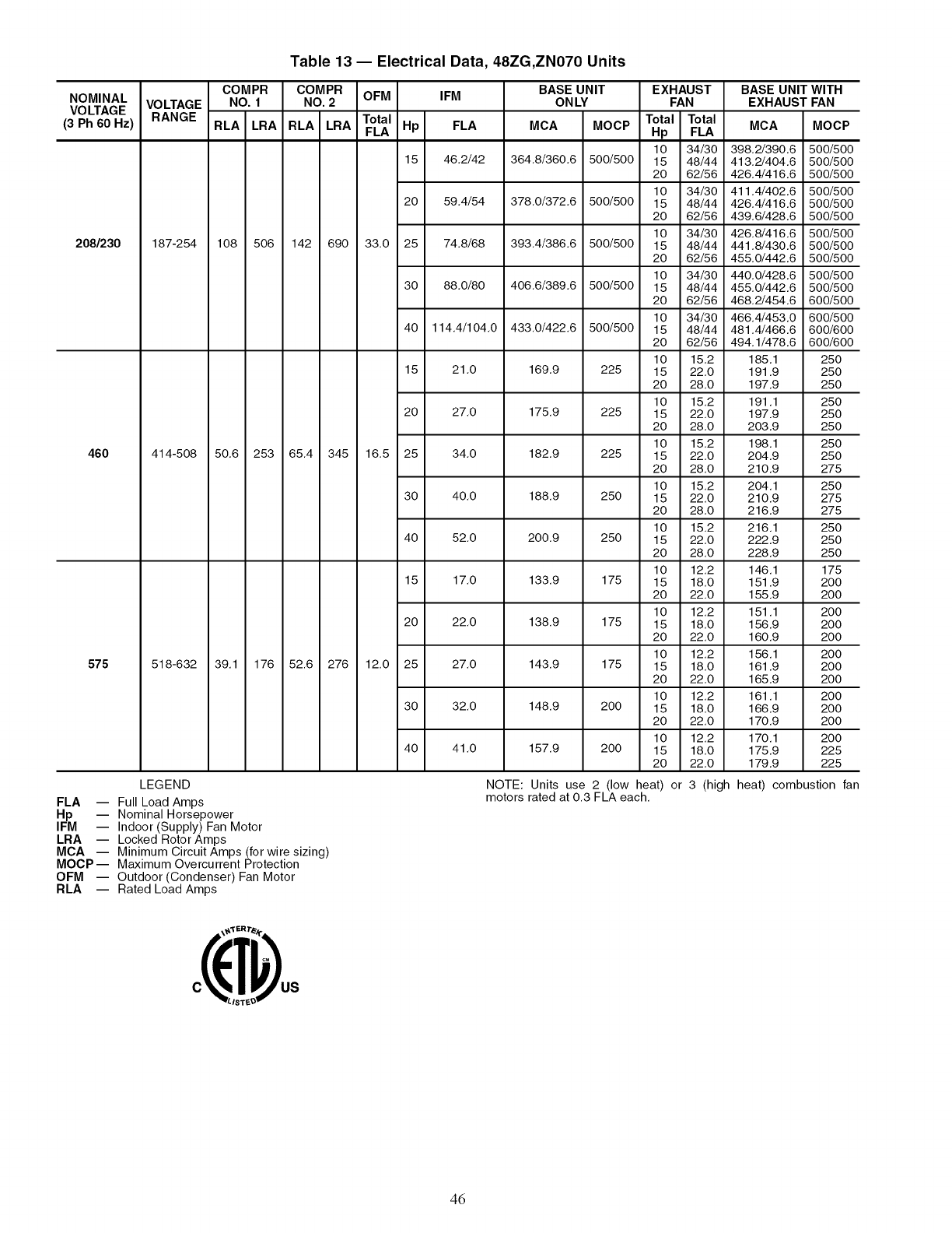
Table 13- Electrical Data, 48ZG,ZN070 Units
NOMINAL
VOLTAGE
(3 Ph 60 Hz)
208/230
460
575
VOLTAGE
RANGE
COMPR
NO. 1
RLA LRA
COMPR OFM IFM
NO. 2
RLA LRA Total Hp FLA
FLA
15 46.2/42
20 59.4/54
187-254 108 506 142 690 33.0 25 74.8_8
30 88.0/80
40 114.4/104.0
15 21.0
20 27.0
414-508 50.6 253 65.4 345 16.5 25 34.0
30 40.0
40 52.0
15 17.0
20 22.0
518-632 39.1 176 52.6 276 12.0 25 27.0
LEGEND
FLA -- Full Load Amps
Hp -- Nominal Horsepower
IFM -- Indoor (Supply) Fan Motor
LRA -- Locked Rotor Amps
MCA -- Minimum Circuit Amps (for wire sizing)
MOCP-- Maximum Overcurrent Protection
OFM -- Outdoor (Condenser) Fan Motor
RLA -- Rated Load Amps
30 32.0
40 41.0
BASE UNIT EXHAUST
ONLY FAN
MCA MOCP Total Total
Hp FLA
10 34/30
364.8/360.6 500/500 15 48/44
20 62/56
10 34/30
378.0/372.6 500/500 15 48/44
20 62/56
10 34/30
393.4/386.6 500/500 15 48/44
20 62/56
10 34/30
406.6/389.6 500/500 15 48/44
20 62/56
10 34/30
433.0/422.6 500/500 15 48/44
20 62/56
10 15.2
169.9 225 15 22.0
20 28.0
10 15.2
175.9 225 15 22.0
20 28.0
10 15.2
182.9 225 15 22.0
20 28.0
10 15.2
188.9 250 15 22.0
20 28.0
10 15.2
200.9 250 15 22.0
20 28.0
10 12.2
133.9 175 15 18.0
20 22.0
10 12.2
138.9 175 15 18.0
20 22.0
10 12.2
143.9 175 15 18.0
20 22.0
10 12.2
148.9 200 15 18.0
20 22.0
10 12.2
157.9 200 15 18.0
20 22.0
BASE UNIT WITH
EXHAUST FAN
MCA MOCP
398.2_90.6 500_00
413.2_04.6 500_00
426.4_16.6 500_00
411.4_02.6 500_00
426.4_16.6 500_00
439.6_28.6 500_00
426.8_16.6 500_00
441.8_30.6 500_00
455.0_42.6 500_00
440.0_28.6 500_00
455.0_42.6 500_00
468.2_54.6 600_00
466.4_53.0 600_00
481.4_66.6 600_00
494.1_78.6 600_00
185.1 250
191.9 250
197.9 250
191.1 250
197.9 250
203.9 250
198.1 250
204.9 250
210.9 275
204.1 250
210.9 275
216.9 275
216.1 250
222.9 250
228.9 250
146.1 175
151.9 200
155.9 200
151.1 200
156.9 200
160.9 200
156.1 200
161.9 200
165.9 200
161.1 200
166.9 200
170.9 200
170.1 200
175.9 225
179.9 225
NOTE: Units use 2 (low heat)
motors rated at 0.3 FLA each. or 3 (high heat) combustion fan
/*IST_D
46
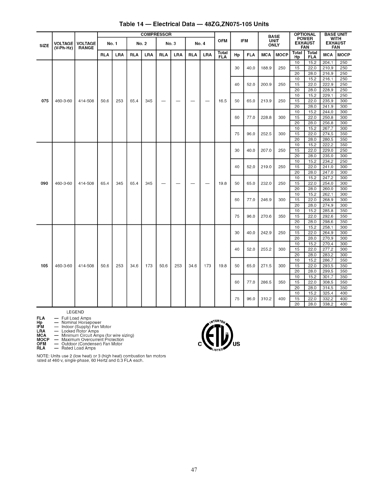
SIZE VOLTAGE VOLTAGE
(V-Ph-Hz) RANGE
Table 14 -- Electrical Data -- 48ZG,ZN075-105 Units
OPTIONAL BASE UNIT
COMPRESSOR BASE POWER WITH
OFM IFM UNIT
No. 1 No. 2 No. 3 No. 4 ONLY EXHAUST EXHAUST
FAN FAN
Total Total
Total Hp FLA MCA MOCP MCA MOCP
RLA LRA RLA LRA RLA LRA RLA LRA FLA Hp FLA
10 15.2 204.1 250
30 40.0 188.9 250 15 22.0 210.9 250
40 52.0 200.9 250
075 460-3-60 414-508 50.6 253 65.4 345 .... 16.5 50 65.0 213.9 250
60 77.0 228.8 300
75 96.0 252.5 300
30 40.0 207.0 250
40 52.0 219.0 250
090 460-3-60 414-508 65.4 345 65.4 345 .... 19.8 50 65.0 232.0 250
60 77.0 246.9 300
75 96.0 270.6 350
30 40.0 242.9 250
40 52.0 255.2 300
105 460-3-60 414-508 50.6 253 34.6 173 50.6 253 34.6 173 19.8 50 65.0 271.5 300
LEGEND
FLA -- Full Load Amps
Hp -- Nominal Horsepower
IFM -- Indoor (Supply) Fan Motor
LRA -- Locked Rotor Amps
MCA -- Minimum Circuit Amps (for wire sizing)
MOCP -- Maximum Overcurrent Protection
OFM -- Outdoor (Condenser) Fan Motor
RLA -- Rated Load Amps
60 77.0 286.5 350
75 96.0 310.2 400
/STE
NOTE: Units use 2 (low heat) or 3 (high heat) combustion fan motors
rated at 460 v, single-phase, 60 Hertz and 0.3 FLA each.
20 28.0 216.9 250
10 15.2 216.1 250
15 22.0 222.9 250
20 28.0 228.9 250
10 15.2 229.1 250
15 22.0 235.9 300
20 28.0 241.9 300
10 15.2 244.0 300
15 22.0 250.8 300
20 28.0 256.8 300
10 15.2 267.7 300
15 22.0 274.5 350
20 28.0 280.5 350
10 15.2 222.2 350
15 22.0 229.0 250
20 28.0 235.0 300
10 15.2 234.2 250
15 22.0 241.0 300
20 28.0 247.0 300
10 15.2 247.2 300
15 22.0 254.0 300
20 28.0 260.0 300
10 15.2 262.1 300
15 22.0 268.9 300
20 28.0 274.9 300
10 15.2 285.8 350
15 22.0 292.6 350
20 28.0 298.6 350
10 15.2 258.1 300
15 22.0 264.9 300
20 28.0 270.9 300
10 15.2 270.4 300
15 22.0 277.2 300
20 28.0 283.2 300
10 15.2 286.7 350
15 22.0 293.5 350
20 28.0 299.5 350
10 15.2 301.7 350
15 22.0 308.5 350
20 28.0 314.5 350
10 15.2 325.4 400
15 22.0 332.2 400
20 28.0 338.2 400
47
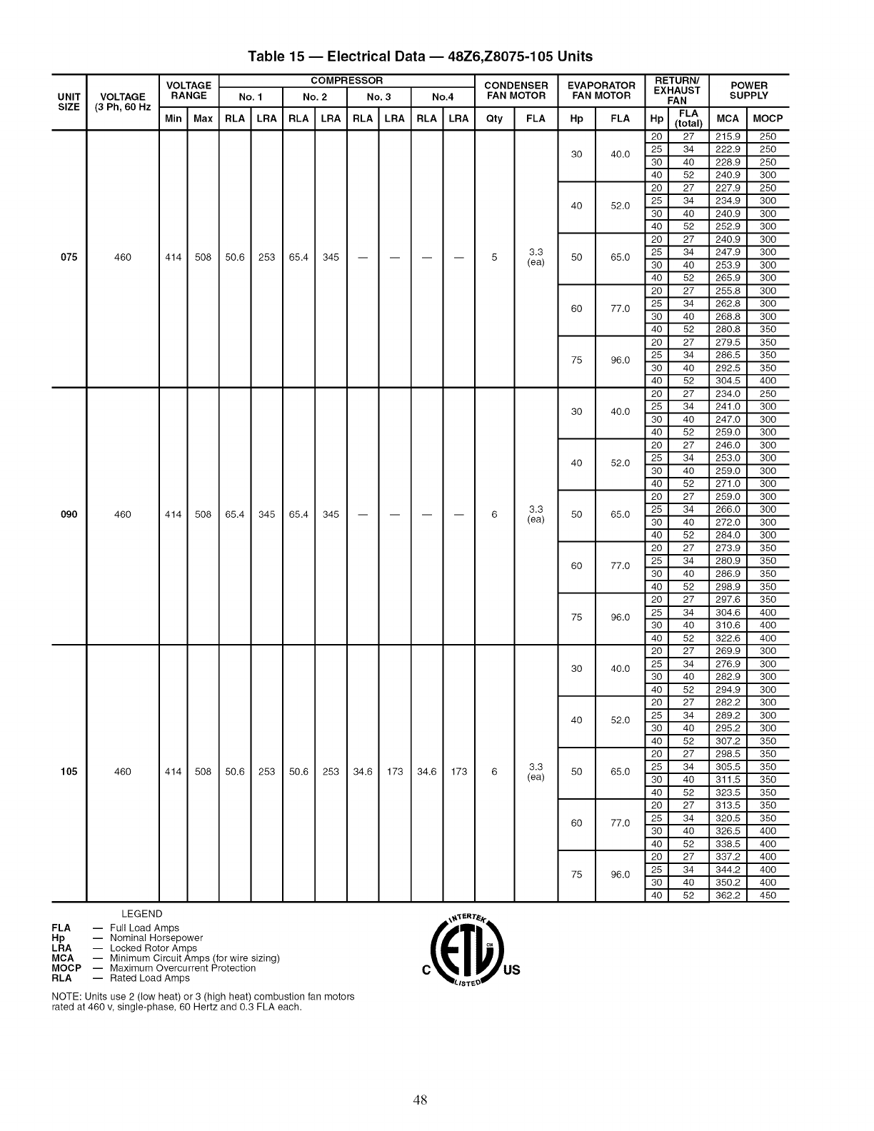
UNIT VOLTAGE
SIZE (3 Ph, 60 Hz
075 460
090 460
105 460
VOLTAGE
RANGE
Table 15 -- Electrical Data -- 48Z6,Z8075-105 Units
COMPRESSOR CONDENSER EVAPORATOR
No. 1 No. 2 No. 3 No.4 FAN MOTOR FAN MOTOR
HpMin Max RLA LRA RLA LRA RLA LRA RLA LRA Qty FLA
414 508 50.6 253 65.4 345 --
414 508 65.4 345 65.4 345 --
414 508 50.6 253 50.6 253 34.6 173 34.6 173 6
3O
LEGEND
FLA -- Full Load Amps
Hp -- Nominal Horsepower
LRA -- Locked Rotor Amps
MCA -- Minimum Circuit Amps (for wire sizing)
MOCP -- Maximum Overcurrent Protection
RLA -- Rated Load Amps
4O
NOTE: Units use 2 (low heat) or 3 (high heat) combustion fan motors
rated at 460 v, single-phase, 60 Hertz and 0.3 FLA each.
3.3
(ea) 50
6O
75
3O
4O
3.3
(ea) 50
6O
75
3O
4O
3.3 50
(ea)
6O
75
RETURN/
EXHAUST POWER
SUPPLY
FAN
FLA
FLA Hp (total) MCA MOCP
20 27 215.9 250
25 34 222.9 250
40.0 30 40 228.9 250
40 52 240.9 300
20 27 227.9 250
25 34 234.9 300
52.0 30 40 240.9 300
40 52 252.9 300
20 27 240.9 300
25 34 247.9 300
65.0 30 40 253.9 300
40 52 265.9 300
20 27 255.8 300
25 34 262.8 300
77.0 30 40 268.8 300
40 52 280.8 350
20 27 279.5 350
25 34 286.5 350
96.0 30 40 292.5 350
40 52 304.5 400
20 27 234.0 250
25 34 241.0 300
40.0 30 40 247.0 300
40 52 259.0 300
20 27 246.0 300
25 34 253.0 300
52.0 30 40 259.0 300
40 52 271.0 300
20 27 259.0 300
25 34 266.0 300
65.0 30 40 272.0 300
40 52 284.0 300
20 27 273.9 350
25 34 280.9 350
77.0 30 40 286.9 350
40 52 298.9 350
20 27 297.6 350
96.0 25 34 304.6 400
30 40 310.6 400
40 52 322.6 400
20 27 269.9 300
40.0 25 34 276.9 300
30 40 282.9 300
40 52 294.9 300
20 27 282.2 300
52.0 25 34 289.2 300
30 40 295.2 300
40 52 307.2 350
20 27 298.5 350
65.0 25 34 305.5 350
30 40 311.5 350
40 52 323.5 350
20 27 313.5 350
77.0 25 34 320.5 350
30 40 326.5 400
40 52 338.5 400
20 27 337.2 400
96.0 25 34 344.2 400
30 40 350.2 400
40 52 362.2 450
LIST_O
48
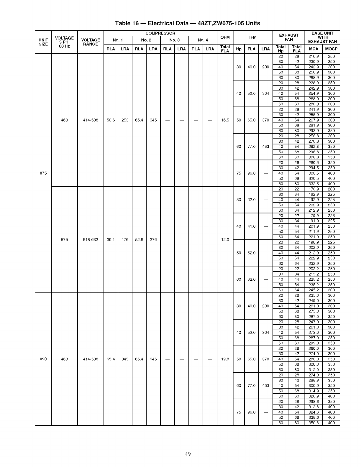
UNIT
SIZE
O75
090
VOLTAGE
3 PH,
60 Hz
460
575
460
VOLTAGE
RANGE
Table 16 -- Electrical Data- 48ZT,ZW075-105 Units
COMPRESSOR BASE UNIT
OFM IFM EXHAUST WITH
No. 1 No. 2 No. 3 No. 4 FAN EXHAUST FAN
Total Total
Total Hp FLA LRA MCA MOCP
RLA LRA RLA LRA RLA LRA RLA LRA FLA Hp FLA
20 28 216.9 250
30 42 230.9 250
30 40.0 230 40 54 242.9 300
50 68 256.9 300
60 80 268.9 300
20 28 228.9 250
30 42 242.9 300
40 52.0 304 40 54 254.9 300
50 68 268.9 300
60 80 280.9 300
20 28 241.9 300
30 42 255.9 300
414-508 50.6 253 65.4 345 .... 16.5 50 65.0 370 40 54 267.9 300
50 68 281.9 300
60 80 293.9 350
20 28 256.8 300
30 42 270.8 300
60 77.0 453 40 54 282.8 350
50 68 296.8 350
60 80 308.8 350
20 28 280.5 350
30 42 294.5 350
75 96.0 -- 40 54 306.5 400
50 68 320.5 400
60 80 332.5 400
20 22 170.9 200
30 34 182.9 225
30 32.0 -- 40 44 192.9 225
50 54 202.9 250
60 64 212.9 250
20 22 179.9 225
30 34 191.9 225
40 41.0 -- 40 44 201.9 250
50 54 211.9 250
60 64 221.9 250
518-632 39.1 176 52.6 276 .... 12.0 20 22 190.9 225
30 34 202.9 250
50 52.0 -- 40 44 212.9 250
50 54 222.9 250
60 64 232.9 250
20 22 203.2 250
30 34 215.2 250
60 62.0 -- 40 44 225.2 250
50 54 235.2 250
60 64 245.2 300
20 28 235.0 300
30 42 249.0 300
30 40.0 230 40 54 261.0 300
50 68 275.0 300
60 80 287.0 350
20 28 247.0 300
30 42 261.0 300
40 52.0 304 40 54 273.0 300
50 68 287.0 350
60 80 299.0 350
20 28 260.0 300
30 42 274.0 300
414-508 65.4 345 65.4 345 .... 19.8 50 65.0 370 40 54 286.0 350
50 68 300.0 350
60 80 312.0 350
20 28 274.9 350
30 42 288.9 350
60 77.0 453 40 54 300.9 350
50 68 314.9 350
60 80 326.9 400
20 28 298.6 350
30 42 312.6 400
75 96.0 -- 40 54 324.6 400
50 68 338.6 400
60 80 350.6 400
49
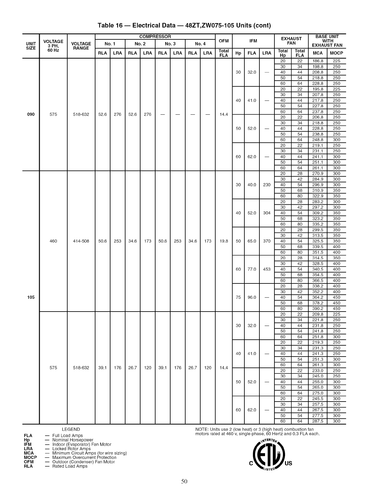
VOLTAGE
UNIT 3 PH,
SIZE 60 Hz
090 575
46O
105
575
Table 16 -- Electrical Data -- 48ZT,ZW075-105 Units (cont)
COMPRESSOR EXHAUST BASE UNIT
OFM IFM WITH
VOLTAGE No. 1 No. 2 No. 3 No. 4 FAN EXHAUST FAN
RANGE Total Total
RLA LRA RLA LRA RLA LRA RLA LRA Total Hp FLA LRA MCA MOCP
FLA Hp FLA
20 22 186.8 225
30 34 198.8 250
30 32.0 -- 40 44 208.8 250
50 54 218.8 250
60 64 228.8 250
20 22 195.8 225
30 34 207.8 250
40 41.0 -- 40 44 217.8 250
50 54 227.8 250
60 64 237.8 250
518-632 52.6 276 52.6 276 .... 14.4 20 22 206.8 250
30 34 218.8 250
50 52.0 -- 40 44 228.8 250
50 54 238.8 250
60 64 248.8 300
20 22 219.1 250
30 34 231.1 250
60 62.0 -- 40 44 241.1 300
50 54 251.1 300
60 64 261.1 300
20 28 270.9 300
30 42 284.9 300
30 40.0 230 40 54 296.9 300
50 68 310.9 350
60 80 322.9 350
20 28 283.2 300
30 42 297.2 300
40 52.0 304 40 54 309.2 350
50 68 323.2 350
60 80 335.2 350
20 28 299.5 350
30 42 313.5 350
414-508 50.6 253 34.6 173 50.6 253 34.6 173 19.8 50 65.0 370 40 54 325.5 350
518-632 39.1 176 26.7 120 39.1 176 26.7 120 14.4
LEGEND
FLA -- Full Load Amps
Hp -- Nominal Horsepower
IFM -- Indoor (Evaporator) Fan Motor
LRA -- Locked Rotor Amps
MCA -- Minimum Circuit Amps (for wire sizing)
MOCP -- Maximum Overcurrent Protection
OFM -- Outdoor (Condenser) Fan Motor
RLA -- Rated Load Amps
50 68 339.5 400
60 80 351.5 400
20 28 314.5 350
30 42 328.5 400
60 77.0 453 40 54 340.5 400
50 68 354.5 400
60 80 366.5 400
20 28 338.2 400
30 42 352.2 400
75 96.0 -- 40 54 364.2 450
50 68 378.2 450
60 80 390.2 450
20 22 209.8 225
30 34 221.8 250
30 32.0 -- 40 44 231.8 250
50 54 241.8 250
60 64 251.8 300
20 22 219.3 250
30 34 231.3 250
40 41.0 -- 40 44 241.3 250
50 54 251.3 300
60 64 261.3 300
20 22 233.0 250
30 34 245.0 250
50 52.0 -- 40 44 255.0 300
50 54 265.0 300
60 64 275.0 300
20 22 245.5 300
30 34 257.5 300
60 62.0 -- 40 44 267.5 300
50 54 277.5 300
60 64 287.5 300
NOTE: Units use 2 (low heat)or 3 (high heat)combustion fan
motors rated at 460 _ single-phase, 60 Hertz and 0.3 FLA each.
LIST_O
50
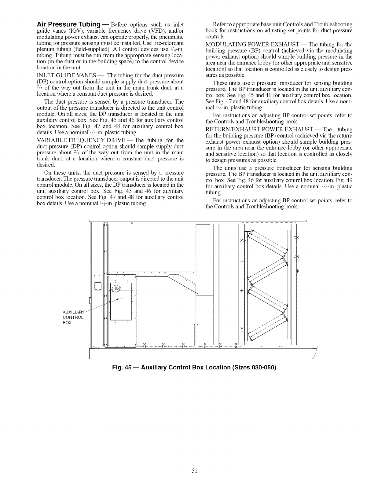
Air Pressure Tubing- Before options such as inlet
guide vanes (IGV), variable frequency drive (VFD), and/or
modulating power exhaust can operate properly, the pneumatic
robing for pressure sensing must be installed. Use fire-retardant
plenum robing (field-supplied). All control devices use V4-in.
robing. Tubing must be mn from the appropriate sensing loca-
tion (in the duct or in the building space) to the control device
location in the unit.
INLET GUIDE VANES -- The tubing for the duct pressure
(DP) control option should sample supply duct pressure about
2/3 of the way out from the unit in the main trunk duct, at a
location where a constant duct pressure is desired.
The duct pressure is sensed by a pressure transducer. The
output of the pressure transducer is directed to the unit control
module. On all sizes, the DP transducer is located in the unit
auxiliary control box. See Fig. 45 and 46 for auxiliary control
box location. See Fig. 47 and 48 for auxiliary control box
details. Use a nominal a/4-in, plastic robing.
VARIABLE FREQUENCY DRIVE -- The robing for the
duct pressure (DP) control option should sample supply duct
pressure about 2/3 of the way out from the unit in the main
trunk duct, at a location where a constant duct pressure is
desired.
On these units, the duct pressure is sensed by a pressure
transducer. The pressure transducer output is directed to the unit
control module. On all sizes, the DP transducer is located in the
unit auxiliary control box. See Fig. 45 and 46 for auxiliary
control box location. See Fig. 47 and 48 for auxiliary control
box details. Use a nominal 1/4-in. plastic tubing.
Refer to appropriate base unit Controls and Troubleshooting
book for instructions on adjusting set points for duct pressure
controls.
MODULATING POWER EXHAUST -- The tubing for the
building pressure (BP) control (achieved via the modulating
power exhaust option) should sample building pressure in the
area near the entrance lobby (or other appropriate and sensitive
location) so that location is controlled as closely to design pres-
sures as possible.
These units use a pressure transducer for sensing building
pressure. The BP transducer is located in the unit auxiliary con-
trol box. See Fig. 45 and 46 for auxiliary control box location.
See Fig. 47 and 48 for auxiliary control box details. Use a nom-
inal 1/4-m. plastic tubing.
For instructions on adjusting BP control set points, refer to
the Controls and Troubleshooting book.
RETURN/EXHAUST POWER EXHAUST -- The tubing
for the building pressure (BP) control (achieved via the return!
exhaust power exhaust option) should sample building pres-
sure in the area near the entrance lobby (or other appropriate
and sensitive location) so that location is controlled as closely
to design pressures as possible.
The units use a pressure transducer for sensing building
pressure. The BP transducer is located in the unit auxiliary con-
trol box. See Fig. 46 for auxiliary control box location. Fig. 49
for auxiliary control box details. Use a nominal 1/4-in. plastic
robing.
For instructions on adjusting BP control set points, refer to
the Controls and Troubleshooting book.
AUXILIARY z
CONTROL
BOX
I
I
Xc
I
I
I
I
I
I
I
I
4I
I
I
I
I
I
I
I
_ _ _ d.......................................................:............................................................:;............................
Fig. 45 -- Auxiliary Control Box Location (Sizes 030-050)
51
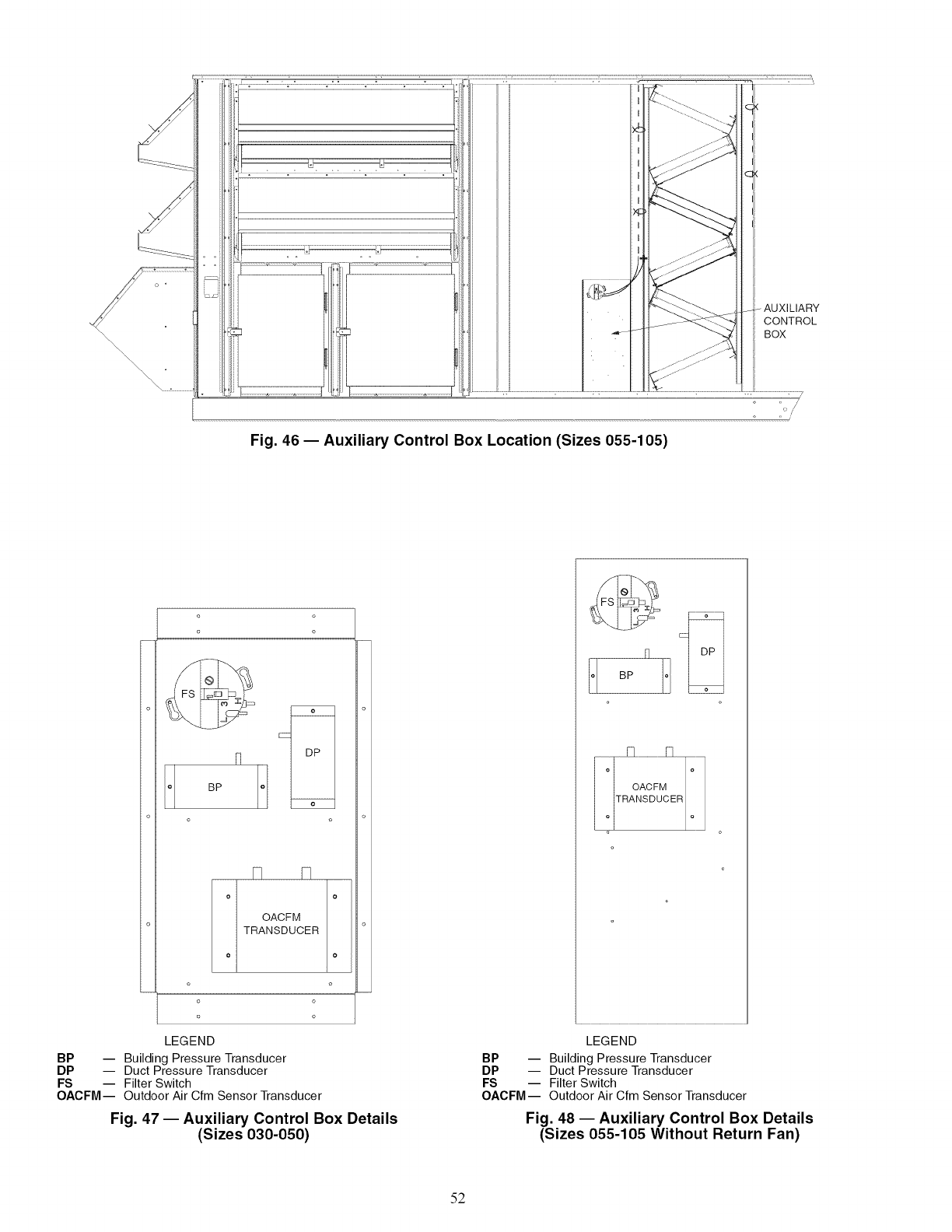
- AUXILIARY
CONTROL
BOX
o o ,J
,, /
Fig. 46- Auxiliary Control Box Location (Sizes 055-105)
o
o
fl
BP o
o
N A
IOACFMI
TRANSDUCER
o o
o o
LEGEND
BP -- Building Pressure Transducer
DP -- Duct Pressure Transducer
FS -- Filter Switch
OACFM-- Outdoor Air Cfm Sensor Transducer
Fig. 47 -- Auxiliary Control Box Details
(Sizes 030-050)
oBP o
LEGEND
BP -- Building Pressure Transducer
DP -- Duct Pressure Transducer
FS -- Filter Switch
OACFM-- Outdoor Air Cfm Sensor Transducer
Fig. 48 -- Auxiliary Control Box Details
(Sizes 055-105 Without Return Fan)
52
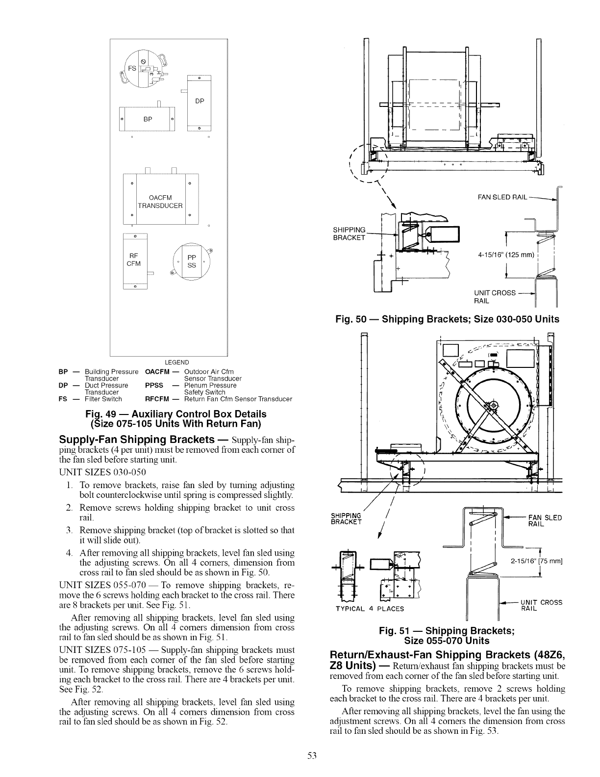
[1'
i .1_
i [+ + ÷ .. --
.q5
\_ FAN SLED RAImLm__
SHIPPING_ I
BRACKET
4-15/16" 125
UNIT CROSS
RAIL
Fig. 50 -- Shipping Brackets; Size 030-050 Units
LEGEND
BP -- Building Pressure OACFM -- OutdoorAir Cfm
Transducer Sensor Transducer
DP -- Duct Pressure PPSS -- Plenum Pressure
Transducer Safety Switch
FS -- Filter Switch RFCFM -- Return Fan Cfm Sensor Transducer
Fig. 49 -- Auxiliary Control Box Details
(Size 075-105 Units With Return Fan)
Supply-Fan Shipping Brackets -- Supply-fan ship-
ping brackets (4 per unit) must be removed from each corner of
the fan sled before starting unit.
UNIT SIZES 030-050
1.
2.
3.
4.
To remove brackets, raise fan sled by turning adjusting
bolt counterclockwise until spring is compressed slightly.
Remove screws holding shipping bracket to unit cross
rail.
Remove shipping bracket (top of bracket is slotted so that
it will slide out).
After removing all shipping brackets, level fan sled using
the adjusting screws. On all 4 corners, dimension from
cross rail to fan sled should be as shown in Fig. 50.
UNIT SIZES 055-070--To remove shipping brackets, re-
move the 6 screws holding each bracket to the cross rail. There
are 8 brackets per unit. See Fig. 51.
After removing all shipping brackets, level fan sled using
the adjusting screws. On all 4 corners dimension from cross
rail to fan sled should be as shown in Fig. 51.
UNIT SIZES 075-105--Supply-fan shipping brackets must
be removed from each corner of the fan sled before starting
unit. To remove shipping brackets, remove the 6 screws hold-
ing each bracket to the cross rail. There are 4 brackets per unit.
See Fig. 52.
After removing all shipping brackets, level fan sled using
the adjusting screws. On all 4 corners dimension from cross
rail to fan sled should be as shown in Fig. 52.
/
SHIPPING //
BRACKET /
TYPICAL 4 PLACES
SLE0
RAIL
2-15/16" [75 mm]
•i ---i UNIT CROSS
RAIL
Fig. 51 -- Shipping Brackets;
Size 055-070 Units
Return/Exhaust-Fan Shipping Brackets (48Z6,
Z8 Units) -- Return!exhaust fan shipping brackets must be
removed from each corner of the fan sled before starting unit.
To remove shipping brackets, remove 2 screws holding
each bracket to the cross rail. There are 4 brackets per unit.
After removing all shipping brackets, level the fan using the
adjustment screws. On all 4 corners the dimension from cross
rail to fan sled should be as shown in Fig. 53.
53
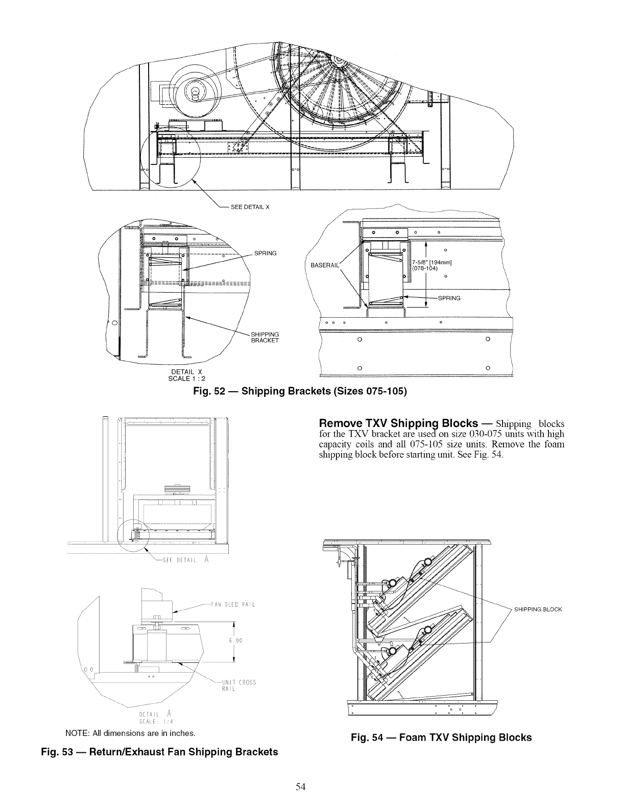
SEE DETAIL X
SPR,NG
DETAIL X
SCALE 1 : 2
o o o
o o o o
t o
7-5/8" [194mm]
(078-104)
--- _RING
e
o
0 o
o 0
Fig. 52 -- Shipping Brackets (Sizes 075-105)
Remove TXV Shipping Blocks _ Shipping blocks
for the TXV bracket are used on size 030-075 units with high
capacity coils and all 075-105 size units. Remove the foam
shipping block before starting unit. See Fig. 54.
SEE [)EI A I xs
'? 0 i....
i _ .......
" ............U!'I ] (lOSS
RA L
s:, _ A
'/' "t
NOTE: All dimensions are in inches.
Fig. 53 -- Return/Exhaust Fan Shipping Brackets
SHIPPING BLOCK
Fig. 54 -- Foam TXV Shipping Blocks
54
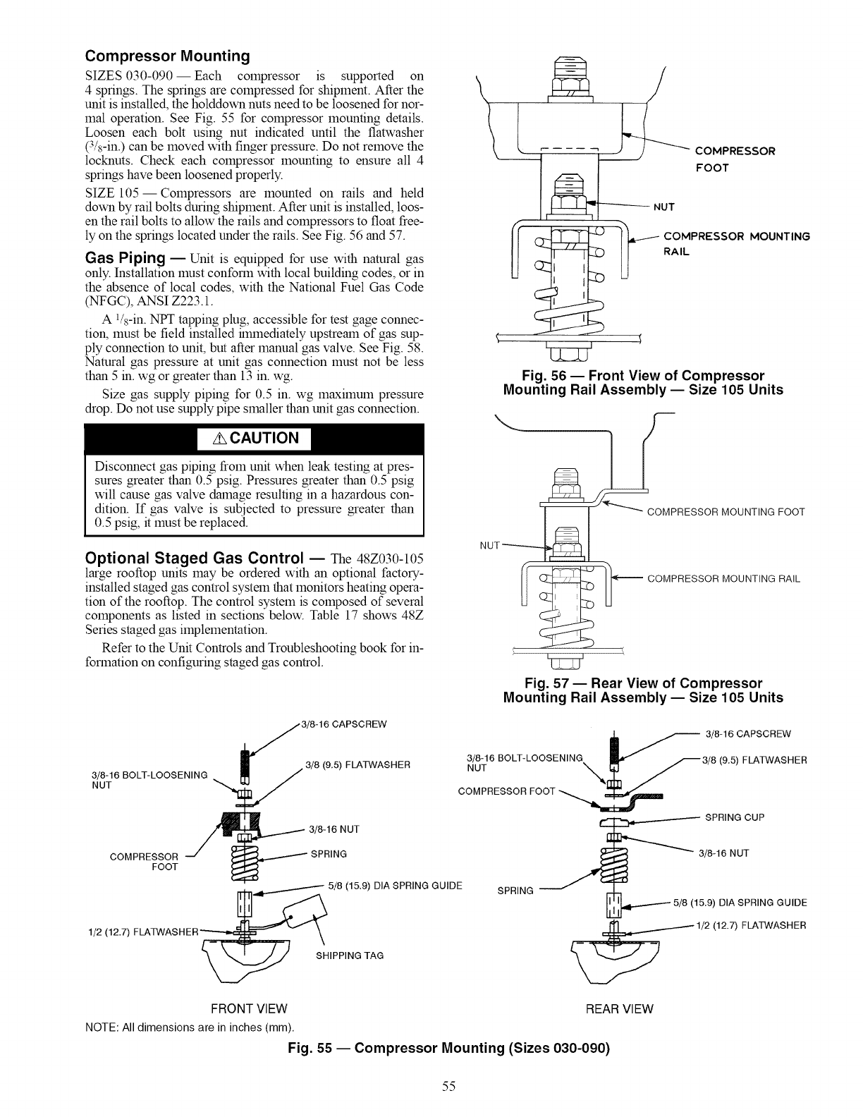
Compressor Mounting
SIZES 030-090 -- Each compressor is supported on
4 springs. The springs are compressed for shipment. After the
unit is installed, the holddown nuts need to be loosened for nor-
mal operation. See Fig. 55 for compressor mounting details.
Loosen each bolt using nut indicated until the flatwasher
(3/s-in.) can be moved with finger pressure. Do not remove the
locknuts. Check each compressor mounting to ensure all 4
springs have been loosened properly.
SIZE 105- Compressors are mounted on rails and held
down by rail bolts during shipment. After unit is installed, loos-
en the rail bolts to allow the rails and compressors to float free-
ly on the springs located under the rails. See Fig. 56 and 57.
Gas Piping -- Unit is equipped for use with natural gas
only. Installation must conform with local building codes, or in
the absence of local codes, with the National Fuel Gas Code
(NFGC), ANSI Z223.1.
A 1&-in. NPT tapping plug, accessible for test gage connec-
tion, must be field installed hmnediately upstream of gas sup-
ply connection to unit, but after manual gas valve. See Fig. 58.
Natural gas pressure at unit gas connection must not be less
than 5 in. wg or greater than 13 in. wg.
Size gas supply piping for 0.5 in. wg maximum pressure
drop. Do not use supply pipe smaller than unit gas connection.
Disconnect gas piping from unit when leak testing at pres-
sures greater than 0.5 psig. Pressures greater than 0.5 psig
will cause gas valve damage resulting in a hazardous con-
dition. If gas valve is subjected to pressure greater than
0.5 psig, it must be replaced.
Optional Staged Gas Control -- The 48Z030-105
large rooftop units may be ordered with an optional factory-
installed staged gas control system that monitors heating opera-
tion of the rooftop. The control system is composed of several
components as listed in sections below. Table 17 shows 48Z
Series staged gas implementation.
Refer to the Unit Controls and Troubleshooting book for in-
formation on configuring staged gas control.
3/8-16 BOLT-LOOSENING
NUT
COMPRESSOR
FOOT 4
3/8-16 CAPSCREW
_,, 3/8 (9,5) FLATWASHER
_._ 3/8-16 NUT
_ SPRING
, _ 5/8 (15.9) DIA SPRING GUIDE
1/2 (12.7) FLATWASHER _
S'HIPPING TAG
_COMPRESSOR
FOOT
NUT
COMPRESSOR MOUNTING
RAIL
Fig. 56 -- Front View of Compressor
Mounting Rail Assembly- Size 105 Units
RESSOR MOUNTING FOOT
/ OOMPRESSORMOUNT,NGRA,L
Fig. 57 -- Rear View of Compressor
Mounting Rail Assembly- Size 105 Units
i _ 3/8-16CAPSCREW
3/8-16 BOLT-LOOSENING _ _ 3/8 (9.5_ FLATWASHER
COMPRESSOR FOOT
_ SPRING CUP
SPRING _ _ 3/8-16 NUT
I __[_....._ 5/8 (15.9) DIA SPRING GUIDE
1/2 (12.7) FLATWASHER
FRONT VIEW REAR VIEW
NOTE: All dimensions are in inches (mm).
Fig. 55 -- Compressor Mounting (Sizes 030-090)
55
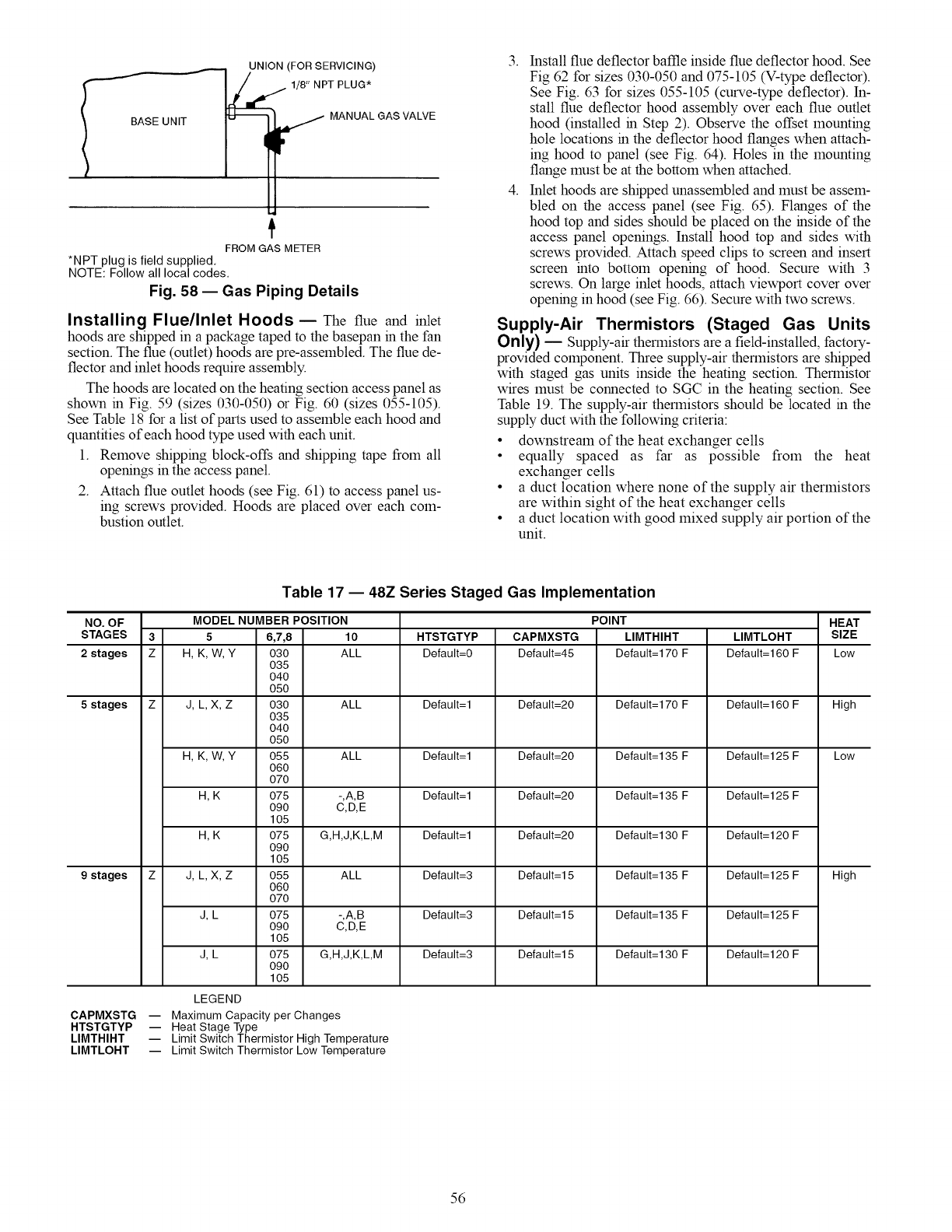
JNION (FOR SERVICING)
1/8" NPT PLUG*
MANUAL GAS VALVE
t
FROM GAS METER
*NPT plug is field supplied,
NOTE: Follow all local codes,
Fig. 58 -- Gas Piping Details
Installing Flue/Inlet Hoods -- The flue and inlet
hoods are shipped in a package taped to the basepan in the fan
section. The flue (outlet) hoods are pre-assembled. The flue de-
flector and inlet hoods require assembly.
The hoods are located on the heating section access panel as
shown in Fig. 59 (sizes 030-050) or Fig. 60 (sizes 055-105).
See Table 18 for a list of parts used to assemble each hood and
quantities of each hood type used with each unit.
1. Remove shipping block-offs and shipping tape from all
openings in the access panel.
2. Attach flue outlet hoods (see Fig. 61) to access panel us-
ing screws provided. Hoods are placed over each com-
bustion outlet.
3. Install flue deflector baffle inside flue deflector hood. See
Fig 62 for sizes 030-050 and 075-105 (V-type deflector).
See Fig. 63 for sizes 055-105 (curve-type deflector). In-
stall flue deflector hood assembly over each flue outlet
hood (installed in Step 2). Observe the offset mounting
hole locations in the deflector hood flanges when attach-
ing hood to panel (see Fig. 64). Holes in the mounting
flange must be at the bottom when attached.
4. Inlet hoods are shipped unassembled and must be assem-
bled on the access panel (see Fig. 65). Flanges of the
hood top and sides should be placed on the inside of the
access panel openings. Install hood top and sides with
screws provided. Attach speed clips to screen and insert
screen into bottom opening of hood. Secure with 3
screws. On large inlet hoods, attach viewport cover over
opening in hood (see Fig. 66). Secure with two screws.
Supply-Air Thermistors (Staged Gas Units
Only) -- Supply-air thermistors are a field-installed, factory-
provided component. Three supply-air thermistors are shipped
with staged gas units inside the heating section. Thermistor
wires must be connected to SGC in the heating section. See
Table 19. The supply-air thermistors should be located in the
supply duct with the following criteria:
• downstream of the heat exchanger cells
• equally spaced as far as possible from the heat
exchanger cells
• a duct location where none of the supply air thermistors
are within sight of the heat exchanger cells
• a duct location with good mixed supply air portion of the
unit.
NO. OF
STAGES
2 stages
5 stages
9 stages
CAPMXSTG
HTSTGTYP
LIMTHIHT
LIMTLOHT
3
Z
Table 17 -- 48Z Series Staged Gas Implementation
MODEL NUMBER POSITION
5 6,7,8 10
H, K, W, Y 030 ALL
O35
O4O
O5O
J, L, X, Z030 ALL
O35
O4O
O5O
H, K, W, Y 055 ALL
O6O
O7O
H, K 075 -,A,B
090 C,D,E
1O5
H, K 075 G,H,J,K,L,M
O9O
1O5
J, L, X, Z055 ALL
O6O
O7O
J, L 075 -,A,B
090 C,D,E
1O5
J, L 075 G,H,J,K,L,M
O9O
1O5
LEGEND
-- Maximum Capacity per Changes
-- Heat Stage Type
-- Limit Switch Thermistor High Temperature
-- Limit Switch Thermistor Low Temperature
HTSTGTYP
Default=0
Default=l
Default=l
Default=l
Default=l
Default=3
Default=3
Default=3
POINT
CAPMXSTG
Default=45
Default=20
Default=20
Default=20
Default=20
Default=l 5
Default=l 5
Default=l 5
LIMTHIHT
Default=170 F
Default=170 F
Default=135 F
Default=135 F
Default=130 F
Default=135 F
Default=135 F
Default=130 F
LIMTLOHT
Default=160 F
Default=160 F
Default=125 F
Default=125 F
Default=120 F
Default=125 F
Default=125 F
Default=120 F
HEAT
SIZE
Low
High
Low
High
56
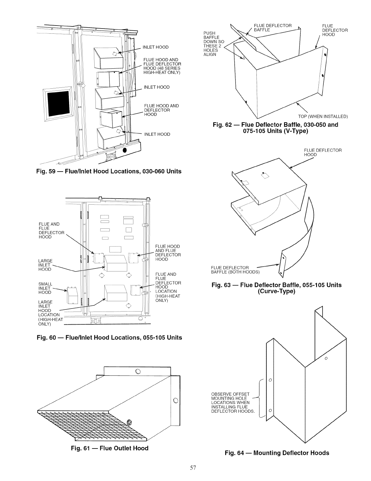
INLET HOOD
FLUE HOOD AND
FLUE DEFLECTOR
HOOD (48 SERIES
HIGH-HEAT ONLY)
INLET HOOD
PUSH
BAFFLE
DOWN SO
THESE 2
HOLES
ALIGN
FLUE DEFLECTOR FLUE
BAFFLE DEFLECTOR
HOOD
FLUE HOOD AND
DEFLECTOR
HOOD
INLET HOOD
TOP (WHEN INSTALLED)
Fig. 62 -- Flue Deflector Baffle, 030-050 and
075-105 Units (V-Type)
FLUE DEFLECTOR
HOOD
Fig. 59 -- Flue/Inlet Hood Locations, 030-060 Units
(HIGH-HEAT C) °
ONLY)
Fig. 60- Flue/Inlet Hood Locations, 055-105 Units
©
I
Ol
FLUE DEFLECTOR
BAFFLE (BOTH HOODS)
Fig. 63 -- Flue Deflector Baffle, 055-105 Units
(Curve-Type)
OBSERVE OFFSET
MOUNTING HOLE
LOCATIONS WHEN
INSTALLING FLUE
DEFLECTOR HOODS,
Fig. 61 -- Flue Outlet Hood Fig. 64 -- Mounting Deflector Hoods
57
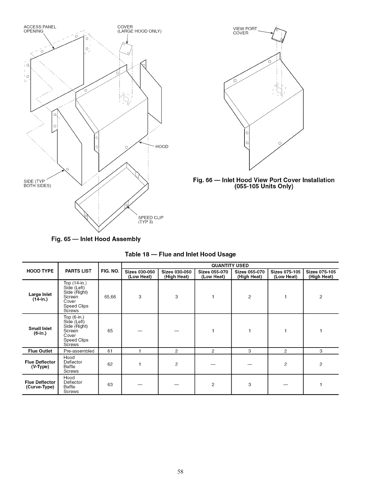
ACCESS PANEL
OPENING X
J
/
<
COVER
(LARGE HOOD ONLY)
i
VIEW PORT /_
cow
"\\\
SIDE (TYP
BOTH SIDES)
Fig. 66 -- Inlet Hood View Port Cover Installation
(055-105 Units Only)
SPEED CLIP
(TYP 3)
Fig. 65 -- Inlet Hood Assembly
HOOD TYPE
Large Inlet
(14-in.)
Small Inlet
(6-in.)
Flue Outlet
Flue Deflector
(V-Type)
Flue Deflector
(Curve-Type)
Table 18 -- Flue and Inlet Hood Usage
PARTS LIST
Top (14-in.)
Side (Left)
Side (Right)
Screen
Cover
Speed Clips
Screws
Top (6-in.)
Side (Left)
Side (Right)
Screen
Cover
Speed Clips
Screws
Pre-assembled
Hood
Deflector
Baffle
Screws
Hood
Deflector
Baffle
Screws
FIG. NO.
65,66
65
61
62
63
Sizes 030-050
(Low Heat)
Sizes 030-050
(High Heat)
QUANTITY USED
Sizes 055-070
(Low Heat)
Sizes 055-070
(High Heat)
Sizes 075-105
(Low Heat)
Sizes 075-105
(High Heat)
3
2
58
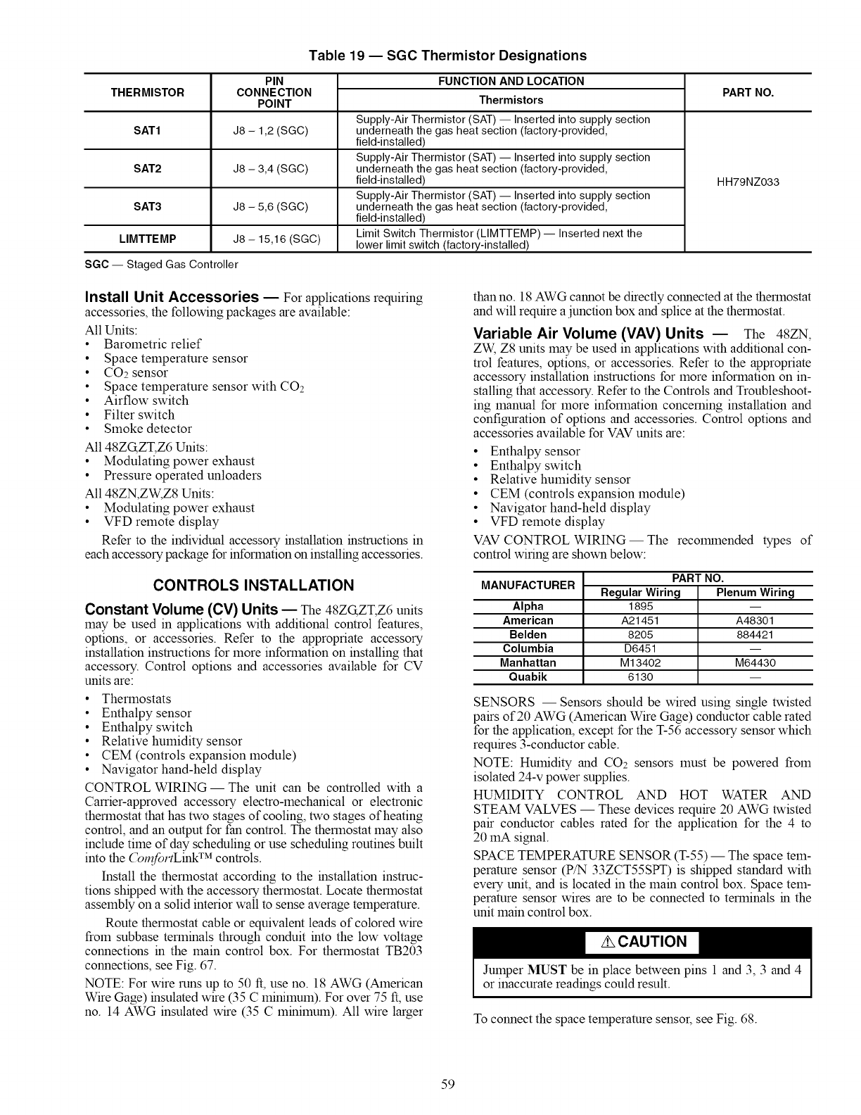
Table 19 -- SGC Thermistor Designations
PIN
CONNECTION
POINT
FUNCTION AND LOCATION
THERMISTOR Thermistors PART NO.
Supply-Air Thermistor (SAT) -- Inserted into supply section
SAT1 J8 - 1,2 (SGC) underneath the gas heat section (factory-provided,
field-installed)
Supply-Air Thermistor (SAT) -- Inserted into supply section
SAT2 J8 - 3,4 (SGC) underneath the gas heat section (factory-provided,
field-installed) HH79NZ033
Supply-Air Thermistor (SAT) -- Inserted into supply section
SAT3 J8 - 5,6 (SGC) underneath the gas heat section (factory-provided,
field-installed)
Limit Switch Thermistor (LIMTTEMP) -- Inserted next the
LIMTTEMP J8 - 15,16 (SGC) lower limit switch (factory-installed)
SGC -- Staged Gas Controller
Install Unit Accessories -- For applications requiring
accessories, the following packages are available:
All Units:
• Barometric relief
• Space temperature sensor
• CO2 sensor
• Space temperature sensor with CO2
• Airflow switch
• Filter switch
• Smoke detector
All 48ZG,ZT,Z6 Units:
• Modulating power exhaust
• Pressure operated unloaders
All 48ZN,ZW, Z8 Units:
• Modulating power exhaust
• VFD remote display
Refer to the individual accessory installation instructions in
each accessory package for information on installing accessories.
CONTROLS INSTALLATION
Constant Volume (CV) Units -- The 48ZG,ZT;Z6 units
may be used in applications with additional control features,
options, or accessories. Refer to the appropriate accessory
installation instructions for more information on installing that
accessory. Control options and accessories available for CV
units are:
• Thermostats
• Enthalpy sensor
• Enthalpy switch
• Relative humidity sensor
• CEM (controls expansion module)
• Navigator hand-held display
CONTROL WIRING- The unit can be controlled with a
Carrier-approved accessory electro-mechanical or electronic
thermostat that has two stages of cooling, two stages of heating
control, and an output for fan control. The thermostat may also
include time of day scheduling or use scheduling routines built
into the (_mfortLink TM controls.
Install the thermostat according to the installation instruc-
tions shipped with the accessory thermostat. Locate thermostat
assembly on a solid interior wall to sense average temperature.
Route thermostat cable or equivalent leads of colored wire
from subbase terminals through conduit into the low voltage
connections in the main control box. For thermostat TB203
connections, see Fig. 67.
NOTE: For wire runs up to 50 ft, use no. 18 AWG (American
Wire Gage) insulated wire (35 C minimum). For over 75 ft, use
no. 14 AWG insulated wire (35 C minimum). All wire larger
than no. 18AWG cannot be directly connected at the thermostat
and will require a junction box and splice at the thermostat.
Variable Air Volume (VAV) Units -- The 48ZN,
ZW, Z8 units may be used in applications with additional con-
trol features, options, or accessories. Refer to the appropriate
accessory installation instructions for more information on in-
stalling that accessory. Refer to the Controls and Troubleshoot-
ing manual for more information concerning installation and
configuration of options and accessories. Control options and
accessories available for VAV units are:
• Enthalpy sensor
• Enthalpy switch
• Relative humidity sensor
• CEM (controls expansion module)
• Navigator hand-held display
• VFD remote display
VAV CONTROL WIRING-- The recolranended types of
control wiring are shown below:
MANUFACTURER
Alpha
American
Belden
Columbia
Manhattan
Quabik
PART NO.
Regular Wiring
1895
A21451
8205
D6451
M13402
6130
PlenumWiring
A48301
884421
M64430
SENSORS -- Sensors should be wired using single twisted
pairs of 20 AWG (American Wire Gage) conductor cable rated
for the application, except for the T-56 accessory sensor which
requires 3-conductor cable.
NOTE: Humidity and CO2 sensors must be powered from
isolated 24-v power supplies.
HUMIDITY CONTROL AND HOT WATER AND
STEAM VALVES -- These devices require 20 AWG twisted
pair conductor cables rated for the application for the 4 to
20 mA signal.
SPACE TEMPERATURE SENSOR (T-55) -- The space tem-
perature sensor (P/N 33ZCT55SPT) is shipped standard with
every unit, and is located in the main control box. Space tem-
perature sensor wires are to be connected to terminals in the
unit main control box.
Jumper MUST be in place between pins 1 and 3, 3 and 4
or inaccurate readings could result.
To connect the space temperature sensor, see Fig. 68.
59
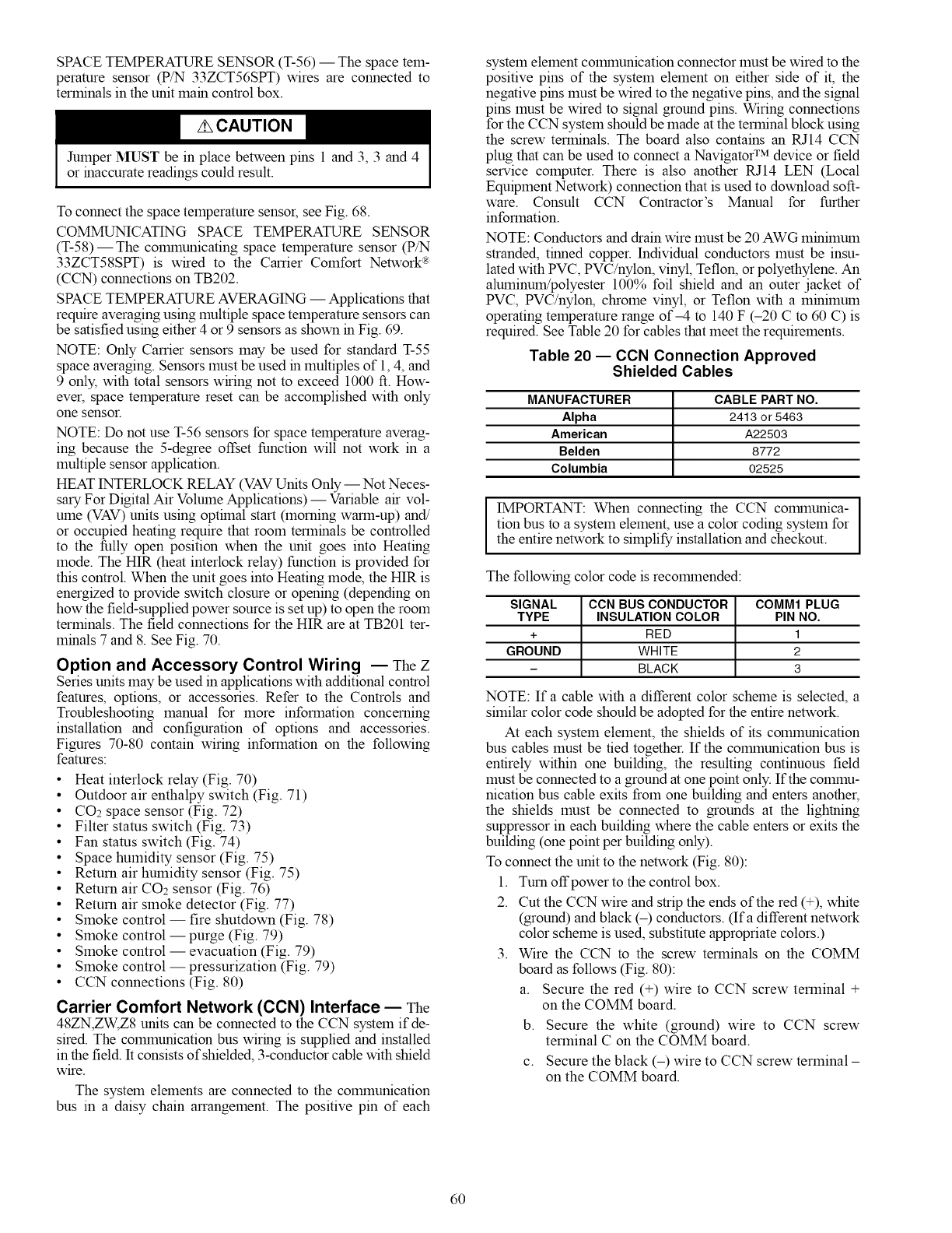
SPACE TEMPERATURE SENSOR (T-56) -- The space tem-
perature sensor (P/N 33ZCT56SPT) wires are connected to
terminals in the unit main control box.
Jumper MUST be in place between pins 1 and 3, 3 and 4
or inaccurate readings could result.
To connect the space temperature sensor, see Fig. 68.
COMMUNICATING SPACE TEMPERATURE SENSOR
(T-58)--The colmnunicating space temperature sensor (P/N
33ZCT58SPT) is wired to the Carrier Comfort Network _-R:
(CCN) connections on TB202.
SPACE TEMPERATURE AVERAGING -- Applications that
require averaging using multiple space temperature sensors can
be satisfied using either 4 or 9 sensors as shown in Fig. 69.
NOTE: Only Carrier sensors may be used for standard T-55
space averaging. Sensors must be used in multiples of 1,4, and
9 only, with total sensors wiring not to exceed 1000 ft. How-
ever, space temperature reset can be accomplished with only
one sensor.
NOTE: Do not use T-56 sensors for space temperature averag-
ing because the 5-degree offset function will not work in a
multiple sensor application.
HEAT INTERLOCK RELAY (VAVUnits Only -- Not Neces-
salTFor Digital Air Volume Applications) -- Variable air vol-
ume (VAV) units using opthnal start (morning warm-up) and/
or occupied heating require that room terminals be controlled
to the fully open position when the unit goes into Heating
mode. The HIR (heat interlock relay) function is provided for
this control. When the unit goes into Heating mode, the HIR is
energized to provide switch closure or opening (depending on
how the field-supplied power source is set up) to open the room
terminals. The field connections for the HIR are at TB201 ter-
minals 7 and 8. See Fig. 70.
Option and Accessory Control Wiring -- The Z
Series units may be used in applications with additional control
features, options, or accessories. Refer to the Controls and
Troubleshooting manual for more information concerning
installation and configuration of options and accessories.
Figures 70-80 contain wiring information on the following
features:
• Heat interlock relay (Fig. 70)
• Outdoor air enthalpy switch (Fig. 71)
• CO2 space sensor (Fig. 72)
• Filter status switch (Fig. 73)
• Fan status switch (Fig. 74)
• Space humidity sensor (Fig. 75)
• Return air humidity sensor (Fig. 75)
• Return air CO2 sensor (Fig. 76)
• Return air smoke detector (Fig. 77)
• Smoke control -- fire shutdown (Fig. 78)
• Smoke control- purge (Fig. 79)
• Smoke control -- evacuation (Fig. 79)
• Smoke control -- pressurization (Fig. 79)
• CCN connections (Fig. 80)
Carrier Comfort Network (CCN) Interface -- The
48ZN,ZW,Z8 units can be connected to the CCN system if de-
sired. The colmnunication bus wiring is supplied and installed
in the field. It consists of shielded, 3-conductor cable with shield
wire.
The system elements are connected to the colmnunicafion
bus in a daisy chain arrangement. The positive pin of each
system element COlrnnunication connector must be wired to the
positive pins of the system element on either side of it, the
negative pins must be wired to the negative pins, and the signal
pins must be wired to signal ground pins. Wiring connections
for the CCN system should be made at the terminal block using
the screw terminals. The board also contains an RJ14 CCN
plug that can be used to connect a Navigator TM device or field
service computer. There is also another RJ14 LEN (Local
Equipment Network) connection that is used to download soft-
ware. Consult CCN Contractor's Manual for further
information.
NOTE: Conductors and drain wire must be 20 AWG minimum
stranded, tinned copper. Individual conductors must be insu-
lated with PVC, PVC/nylon, vinyl, Teflon, or polyethylene. An
aluminum!polyester 100% foil shield and an outer jacket of
PVC, PVC/nylon, chrome vinyl, or Teflon with a minimum
operating temperature range of-4 to 140 F (-20 C to 60 C) is
required. See Table 20 for cables that meet the requirements.
Table 20 -- CCN Connection Approved
Shielded Cables
MANUFACTURER CABLEPARTNO.
Alpha 2413 or 5463
American A22503
Belden 8772
Columbia 02525
IMPORTANT: When connecting the CCN colrnnunica-
tion bus to a system element, use a color coding system for
the entire network to simplify installation and checkout.
The following color code is recolrnnended:
SIGNAL CCN BUS CONDUCTOR COMM1 PLUG
TYPE INSULATION COLOR PIN NO.
+ RED 1
GROUND WHITE 2
- BLACK 3
NOTE: If a cable with a different color scheme is selected, a
similar color code should be adopted for the entire network.
At each system element, the shields of its colmnunication
bus cables must be tied together. If the colmnunication bus is
entirely within one building, the resulting continuous field
must be connected to a ground at one point only. If the colmnu-
nication bus cable exits from one building and enters another,
the shields must be connected to grounds at the lightning
suppressor in each building where the cable enters or exits the
building (one point per building only).
To connect the unit to the network (Fig. 80):
1. Turn offpower to the control box.
2. Cut the CCN wire and strip the ends of the red (+), white
(ground) and black (-) conductors. (Ira different network
color scheme is used, substitute appropriate colors.)
3. Wire the CCN to the screw terminals on the COMM
board as follows (Fig. 80):
a. Secure the red (+) wire to CCN screw terminal +
on the COMM board.
b. Secure the white (ground) wire to CCN screw
terminal C on the COMM board.
c. Secure the black (-) wire to CCN screw terminal -
on the COMM board.
6O
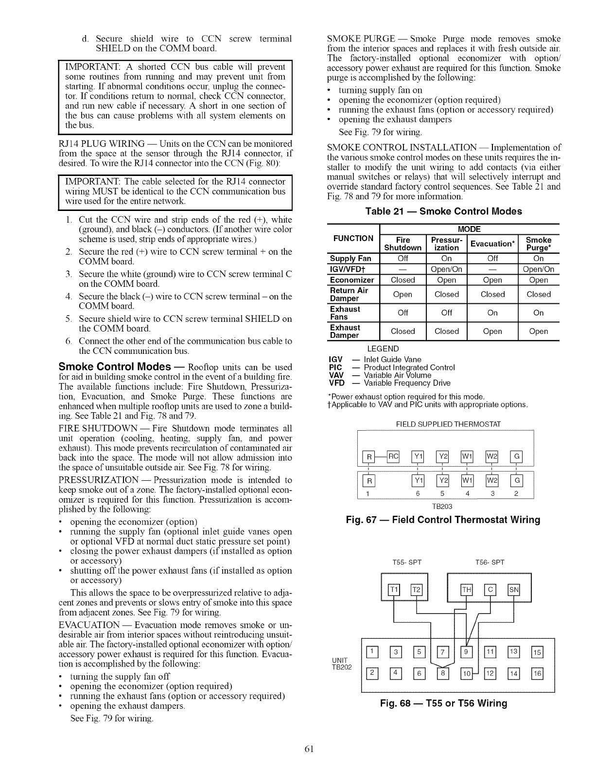
d. Secureshieldwire to CCN screwterminal
SHIELDontheCOMMboard.
IMPORTANT:A shortedCCNbuscablewill prevent
someroutinesfromrunningandmaypreventunitfrom
starting.If abnormalconditionsoccur,unplugtheconnec-
tor.If conditionsreturntonormal,checkCCNconnector,
andrunnewcableif necessary.A shortinonesectionof
thebuscancauseproblemswithallsystemelementson
thebus.
RJ14PLUGWIRING-- UnitsontheCCNcanbemonitored
fromthespaceatthesensorthroughtheRJ14connector,if
desired.TowiretheRJ14connectorintotheCCN(Fig.80):
IMPORTANT:ThecableselectedfortheRJ14connector
wiring MUST be identical to the CCN colmnunication bus
wire used for the entire network.
1.
2.
3.
4.
5.
6.
Cut the CCN wire and strip ends of the red (+), white
(ground), and black (-) conductors. (If another wire color
scheme is used, strip ends of appropriate wires.)
Secure the red (+) wire to CCN screw terminal + on the
COMM board.
Secure the white (ground) wire to CCN screw terminal C
on the COMM board.
Secure the black (-) wire to CCN screw terminal - on the
COMM board.
Secure shield wire to CCN screw terminal SHIELD on
the COMM board.
Connect the other end of the colrnnunication bus cable to
the CCN colrnnunication bus.
Smoke Control Modes -- Rooftop units can be used
for aid in building smoke control in the event of a building fire.
The available functions include: Fire Shutdown, Pressuriza-
tion, Evacuation, and Smoke Purge. These functions are
enhanced when multiple rooftop units are used to zone a build-
ing. See Table 21 and Fig. 78 and 79.
FIRE SHUTDOWN- Fire Shutdown mode terminates all
unit operation (cooling, heating, supply fan, and power
exhaust). This mode prevents recirculation of contaminated air
back into the space. The mode will not allow admission into
the space of unsuitable outside air. See Fig. 78 for wiring.
PRESSURIZATION- Pressurization mode is intended to
keep smoke out of a zone. The factory-installed optional econ-
omizer is required for this function. Pressurization is accom-
plished by the following:
• opening the economizer (option)
• running the supply fan (optional inlet guide vanes open
or optional VFD at normal duct static pressure set point)
• closing the power exhaust dampers (if installed as option
or accessory)
• shutting offthe power exhaust fans (if installed as option
or accessory)
This allows the space to be overpressurized relative to adja-
cent zones and prevents or slows entry of smoke into this space
from adjacent zones. See Fig. 79 for wiring.
EVACUATION- Evacuation mode removes smoke or un-
desirable air from interior spaces without reintroducing unsuit-
able air. The factory-installed optional economizer with option!
accessory power exhaust is required for this function. Evacua-
tion is accomplished by the following:
• turning the supply fan off
• opening the economizer (option required)
• running the exhaust fans (option or accessory required)
• opening the exhaust dampers.
See Fig. 79 for wiring.
SMOKE PURGE--Smoke Purge mode removes smoke
from the interior spaces and replaces it with fresh outside air.
The factory-installed optional economizer with option/
accessory power exhaust are required for this function. Smoke
purge is accomplished by the following:
• turning supply fan on
• opening the economizer (option required)
• running the exhaust fans (option or accessory required)
• opening the exhaust dampers
See Fig. 79 for wiring.
SMOKE CONTROL INSTALLATION -- hnplementation of
the various smoke control modes on these units requires the in-
staller to modify the unit wiring to add contacts (via either
manual switches or relays) that will selectively interrupt and
ovemde standard factory control sequences. See Table 21 and
Fig. 78 and 79 for more information.
Table 21 -- Smoke Control Modes
FUNCTION
Supply Fan
IGV/VFDI"
Economizer
Return Air
Damper
Exhaust
Fans
Exhaust
Damper
Fire
Shutdown
Off
Closed
Open
Off
Closed
LEGEND
MODE
Pressur-
ization
On
Open/On
Open
Closed
Off
Closed
Evacuation* Smoke
Purge*
Off On
-- Open/On
Open Open
Closed Closed
On On
Open Open
IGV -- Inlet Guide Vane
PIC -- Product Integrated Control
VAV -- Variable Air Volume
VFD -- Variable Frequency Drive
*Power exhaust option required for this mode.
l-Applicable to VAV and PIC units with appropriate options.
FIELD SUPPLIED THERMOSTAT
....
1 6 5 4 3 2
TB203
Fig. 67 -- Field Control Thermostat Wiring
D
UNIT
TB202 D
TS5-SPT T56-SPT
%% D
Pq% D
%
%
Fig. 68 -- T55 or T56 Wiring
61
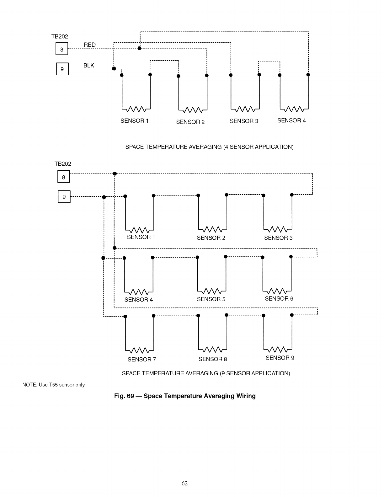
TB202 RED 4,
r- .......... -_-
......#L_K_........O-.
SENSOR 2 SENSOR 3
SENSOR 1 SENSOR 4
SPACE TEMPERATURE AVERAGING (4 SENSOR APPLICATION)
TB202
%
NOTE: Use T55 sensor only.
SENSOR 1 SENSOR 2 SENSOR 3
SENSOR 4 LJ
SENSOR 5 SENSOR 6
..........LT...................U"...............U..........'
SENSOR 7 SENSOR 8 SENSOR 9
SPACE TEMPERATURE AVERAGING (9 SENSOR APPLICATION)
Fig. 69 -- Space Temperature Averaging Wiring
62
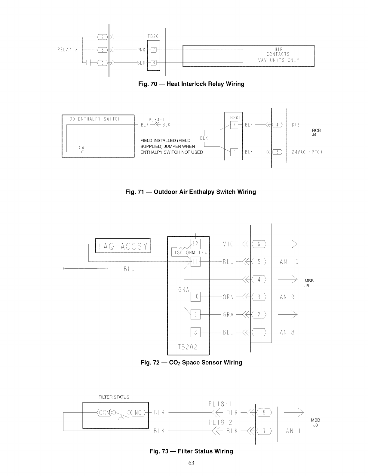
RE AY 3
F)._ /B2o_
F>...................................................PNKj[_J ..........
I I
@ Blu_
lllA
CONTACTS
VAV UNIIS ONLY I
Fig. 70 -- Heat Interlock Relay Wiring
OD EN[/ALPY SW FC
LOW I PL34 I
BLK_BLK ..........................................................................................................................
FIELDINSTALLED(FIELD BLK
SUPPLIED) JUMPER WHEN [
ENTHALPY SWITCH NOT USED
%2011
4IN B K_4 DI2
RCB
J4
24VAC (PIC)
Fig. 71 -- Outdoor Air Enthalpy Switch Wiring
..........................................B/U ........................................................
(}[{A
TB202
..........................rio .............((
sl _..............((
OliN
GRA --(_
........................BLU
AN 10
>
AN 9
AN 8
MBB
J8
Fig. 72 -- CO2 Space Sensor Wiring
FILTER STATUS
[K
B[_K
PI_I8 I
_ B/K
Fig. 73 -- Filter Status Wiring
63
%
J
MBB
J8
AN II
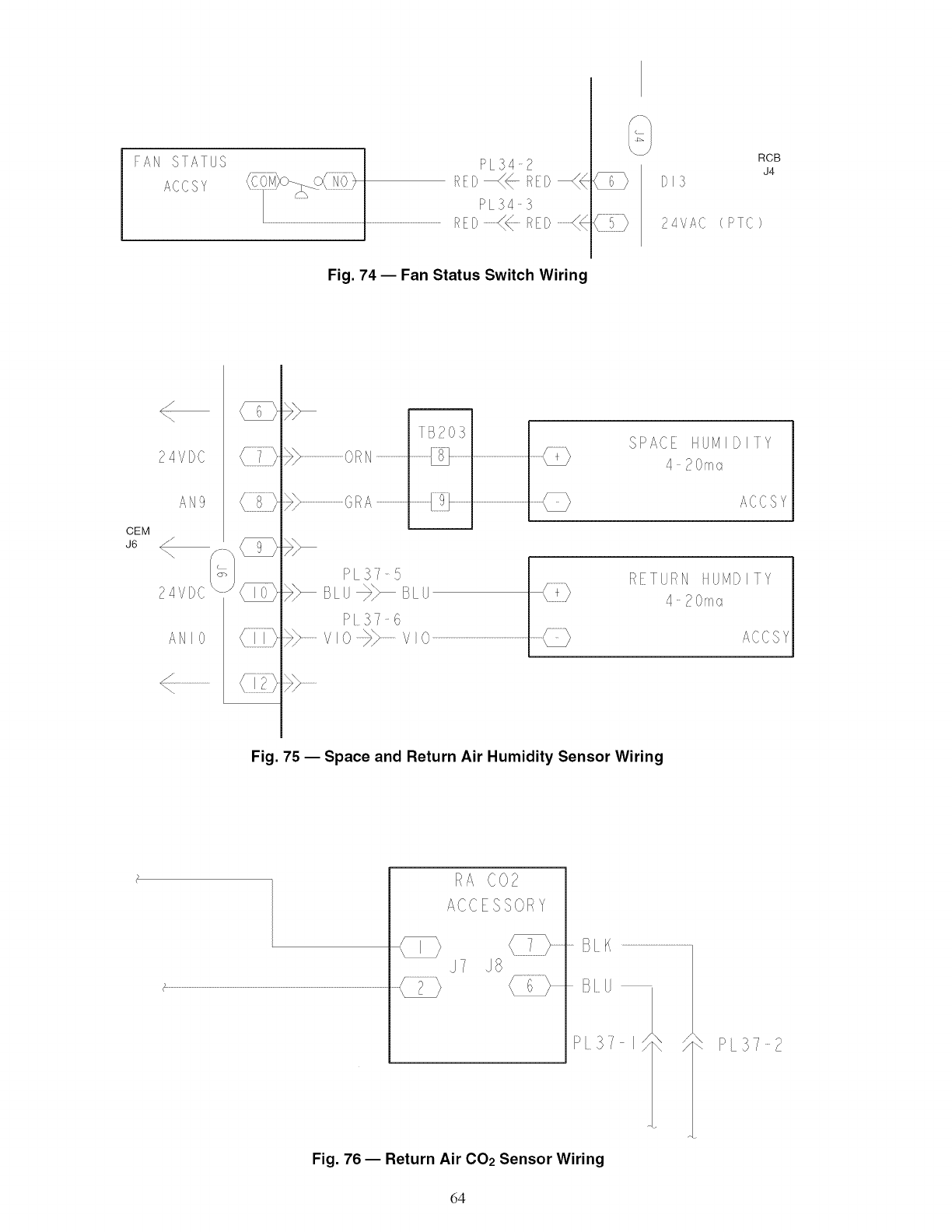
FAN STATUS
ACCSY
PL342
REl}_4- R_:I>_4
PL543
PEP............{< RrD............{< (PTC
RCB
J4
Fig. 74 -- Fan Status Switch Wiring
CEM
J6
?4VDC
AN9
<f
24VDC
ANIO
C_
C_
{]]}
(i}
m
TB20}
>>...................................o/<N............................................._ ..............
PL 37 5
BLU_ BLU
P!37 6
>>..............vo>> ..............vo ...................................................................................
SPACE HUM IDI Y
4 20ma
ACCSY
RET;RN H ;vID ITY
4 20ma
ACCSY
Fig. 75 -- Space and Return Air Humidity Sensor Wiring
RA C02
ACCESSORY
J7
_F PL37 2
Fig. 76 -- Return Air CO2 Sensor Wiring
64
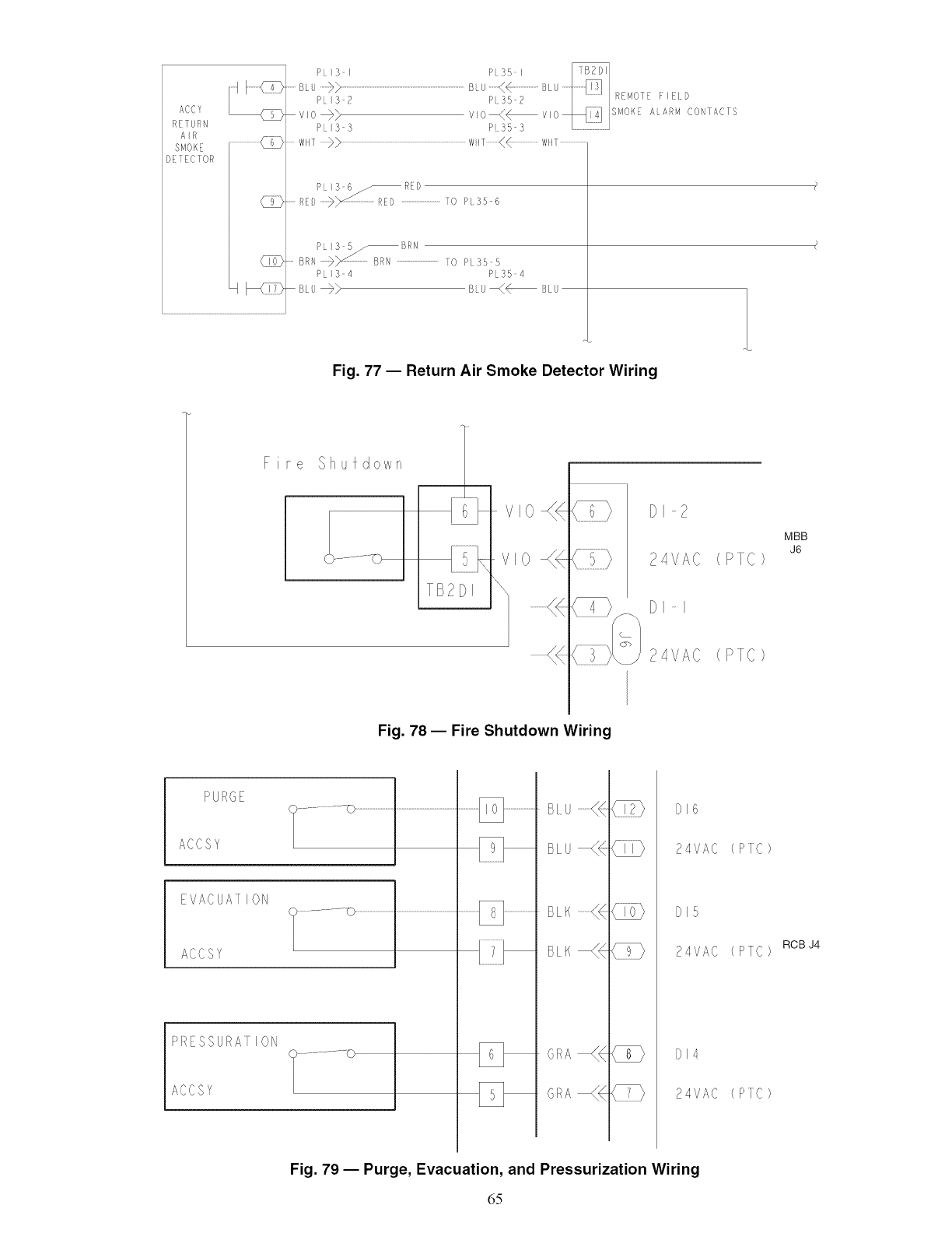
ACC¥
RETURN
AiR ...........................@
SMOK_
DEIEC]OR
(I(:(D
PLI3 I P 35 I
LU >> BLU < .......... BLU
PI_:_2 Pss2 RMo: _lD
v_o_> vo<_v,o_/ q /sM°_,,L,,/_CON1A¢IS
PLI3 3 P 35 3
......Writ_> ..............................................................................................................W_T(+ ....................Writ.......................
PL _3 6/ RED
.......RED RED ..................................o P 35 6
PLI3 b_ f/RN
BRN _y 5F{\ ....................................TO PL35 5
PLI3o4 PL35 4
BLU_} BLU _/<--BLU
Fig. 77 -- Return Air Smoke Detector Wiring
Fire Shu/down 1
TB2DI
vlo4
\
{
C4>
3
( >
24VAC
DI
24VAC
(PIe)
(PTC)
MBB
J6
Fig. 78- Fire Shutdown Wiring
PU:/GE
ACCSY
}................ -0 .................................
EVACUAI ION
ACCSY
>/ESSURA] ION
ACCSY
}................ _0
BE
BE
BL
BI
DI6
24VAC
DIS
24VAC
DI4
24VAC
PIC
PTC
PIC
RCB J4
Fig. 79 -- Purge, Evacuation, and Pressurization Wiring
65
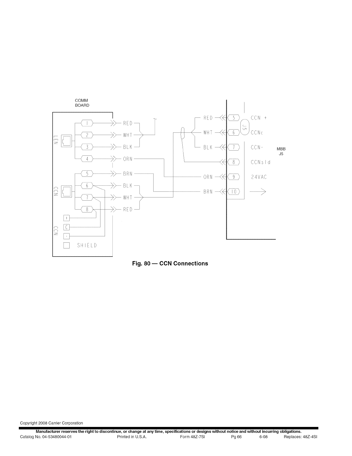
COMM
BOARD
i
RED
_w
...........B K
I
Ill(i}........... _ RD
_q
z_
RED_<
WHT_
BLK_
or_H...........((
BRN...........(<
CCN +
CCNc
CCN
CCNsld
24VAC
MBB
J5
Fig. 80- CCN Connections
Copyright 2008 Carrier Corporation
Manufacturer reserves the right to discontinue, or change at any time, specifications or designs without notice and without incurring obligations.
Catalog No. 04-53480044-01 Printed in U.S.A. Form 48Z-7SI Pg 66 6-08 Replaces: 48Z-4Sl
