CARRIER Package Units(both Units Combined) Manual L0812445
User Manual: CARRIER CARRIER Package Units(both units combined) Manual CARRIER Package Units(both units combined) Owner's Manual, CARRIER Package Units(both units combined) installation guides
Open the PDF directly: View PDF ![]() .
.
Page Count: 4
Installation Instructions
NOTE: Read and become fanfiliar with these instructions before beginning installation.
SAFETY CONSIDERATIONS
Installing and servicing air-conditioning equipment can be
hazardous due to system pressures and electrical components. Only
trained and qualified personnel should install or service
air-conditioning equipment. When working on air-conditioning
equipment, observe the precautions provided in literature, tags, and
labels attached to the unit.
Follow all safety codes. Wear safety glasses, protective clothing,
and work gloves. Use quenching cloth for brazing operations.
Have fire extinguisher available. Read these instructions
thoroughly and follow all warnings or cautions included in
literature and attached to the unit. Consult local building codes and
National Electrical Code (NEC) for special requirements.
Recognize safety information. This is the safety-alert symbol/_.
When you see this symbol on the unit and in instructions or
manuals, be alert to the potential for personal injury.
Understand these signal words: DANGER, WARNING, and
CAUTION. These words are used with the safety-alert symbol.
DANGER identifies the most serious hazards which will result in
severe personal injury or death. WARNING signifies hazards
which could result in personal injury or death. CAUTION is used
to identify unsafe practices which may result in nfinor personal
injury or product and property damage. NOTE is used to highlight
suggestions which will result in enhanced installation, reliability, or
operation.
ELECTRICAL SHOCK HAZARD AND/OR UNIT
OPERATION AND DAMAGE HAZARD
Failure to follow this warning could result in personal injury
or death and/or unit operation and damage.
- Follow the National Electrical Code (NEC) or local
codes and ordinances.
- For personal safety, this unit MUST BE properly
grounded.
- Protective devices (fuses or circuit breakers) acceptable
for unit installations are specified on the nameplate of
each unit.
- DO NOT use an extension cord with this unit.
- Alunfinum building wiring may present special problems.
Consult a qualified electrician for assistance.
When unit is in STOP position, there is still voltage to
electrical controls.
INTRODUCTION
These instructions cover the installation of the 265v Electrical
Subbase Accessory. The 265v Electrical Subbase Accessory
package consists of the electrical subbase, 2 adjustable side
extension panels, power cord cover, and 4 attachment screws.
Table 1--Package Contents
ITEM
Electrical Subbase
Adjustable Side Extension Panels
Power Cord Cover
Attachment Screws (black)
QUANTITY
1
2
1
4
GENERAL
The 265v Electrical Subbase Accessory nmst be used whenever the
packaged ternfinal air conditioner or heat pump is installed in a
wall less than 2 in. (50.8 ram) thick, or where wall sleeve extends 4
in. (101.6 ram) or more into room, or for additional support or
leveling of air conditioner or heat pump. Wall sleeve must be 3-1/4
in. (82.6 ram) minimum into room and 3-1/4 in. (82.6 ram)
nfininmm to 5-1/2 in. (139.7 ram) naaxinmm above floor.
The electrical subbase has a factory-installed electrical junction
box containing a receptacle for corded packaged ternfinal air
conditioner (PTAC) units, Knockouts are provided for power
source connections,
INSTALLATION
IMPORTANT: Refer to chassis nameplate for power source
requirements.
Building power source wiring can enter subbase through any
conduit knockout hole in bottom of subbase or through the
knockouts in the electrical junction box walls.
All wiring must comply with local electrical codes and National
Electrical Code (NEC).
NOTE: The factory-installed receptacle must match the chassis
plug. Refer to PTAC Owner's Manual to choose the correct
subbase.
Step 1 --Disconnect all power to unit and remove front panel.
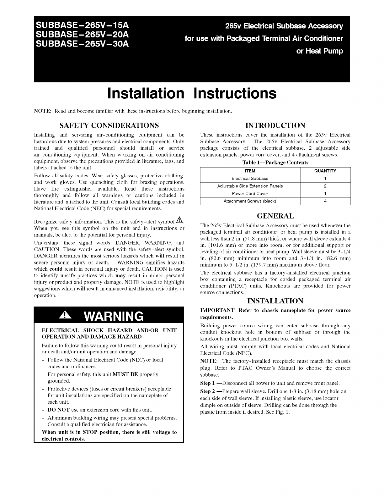
Step 2 --Prepare wall sleeve. Drill one 1/8 in. (3.18 ram) hole on
each side of wall sleeve. If installing plastic sleeve, use locator
dimple on outside of sleeve. Drilling can be done through the
plastic from inside if desired. See Fig. 1.
ADJUSTABLE
SIDE EXTENSION _
ATTACHMENT SCREW- PANELS
SUBBASE TO WALL
SLEEVE NOTE:
PANELS SLIDE INTO
INSIDE OF SUBBASE
ATTACHMENT SCREW-
SUBBASE TO
SIDE PANEL
LEVELING
BOLT
ACCESS
COVERS
BOX
RECEPTACLE
EXTENSION PANELS
SHOWN BENT TO FIT
AGAINST WALL
LOOATOR .... i
E. o,OPLEF
r_ _ _ ADJUSTABLE
I/ SIDE EXTENSION
// I/PANELS
_'1/ _ SIDEI _/_
_,_ TAB !_
ZZ Z ENGAGEMENT
- _J_ HOLES
- ATTACHMENT SCREW-
_ SUBBASE TO WALL
SLEEVE
POWER
CORD LEVELING ATTACHMENT SCREW-SUBBASE
NOTCH BOLT TO SIDE PANEL
A08513
Fig. 1 -Electrical Subbase Assembly
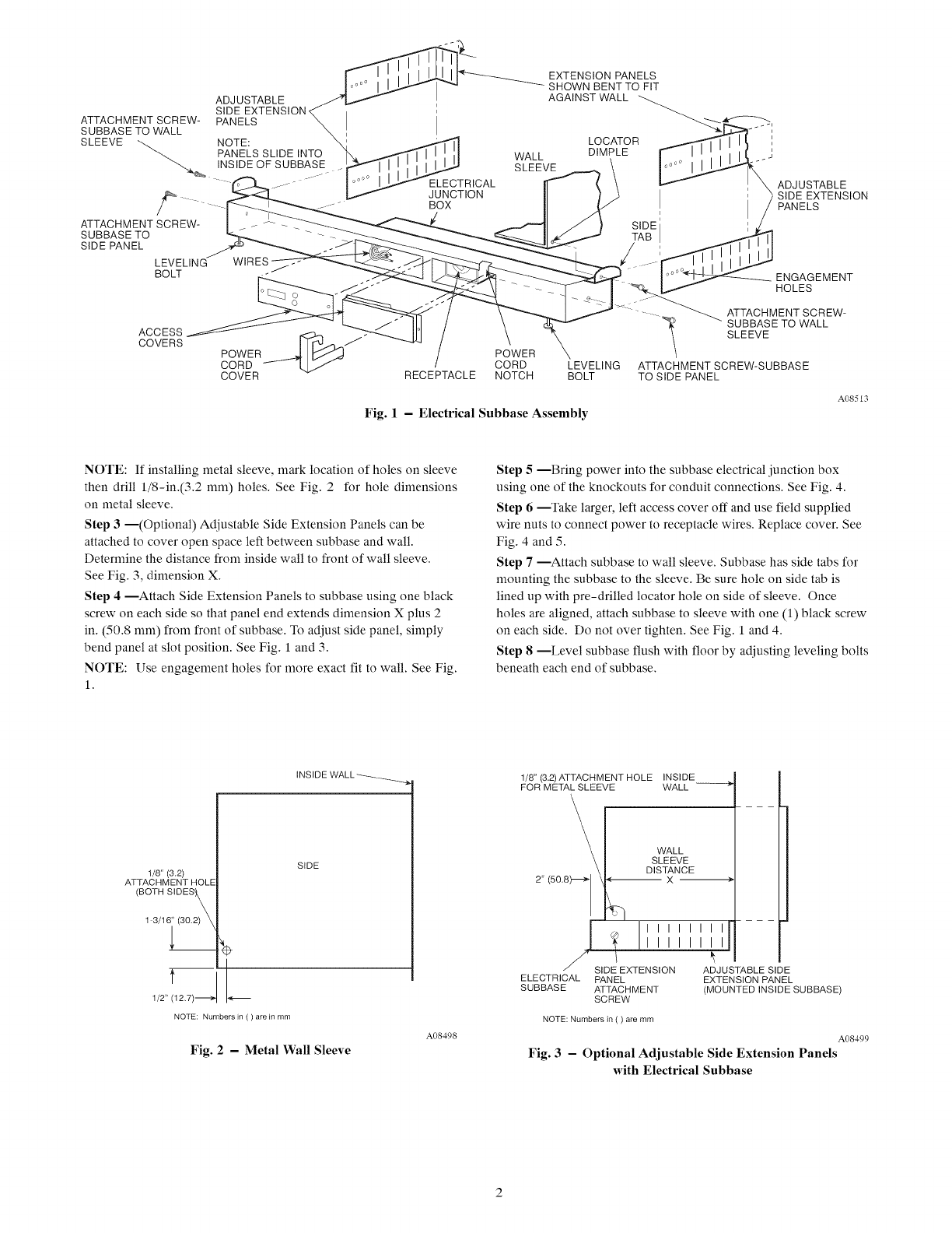
NOTE: If installing metal sleeve, mark location of holes on sleeve
then drill 1/8-in.(3.2 ram) holes. See Fig. 2 for hole dimensions
on metal sleeve.
Step 3 --(Optional) Adjustable Side Extension Panels can be
attached to cover open space left between subbase and wall.
Determine the distance from inside wall to front of wall sleeve.
See Fig. 3, dimension X.
Step 4 --Attach Side Extension Panels to subbase using one black
screw on each side so that panel end extends dimension X plus 2
in. (50.8 ram) from front of subbase. To adjust side panel, simply
bend panel at slot position. See Fig. 1 and 3.
NOTE: Use engagement holes for more exact fit to wall. See Fig.
1.
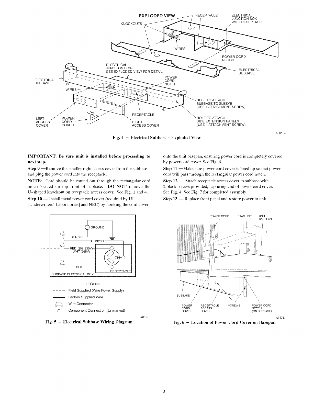
Step 5 --Bring power into the subbase electrical junction box
using one of the knockouts for conduit connections. See Fig. 4.
Step 6 --Take larger, left access cover off and use field supplied
wire nuts to connect power to receptacle wires. Replace cover. See
Fig. 4 and 5.
Step 7 --Attach subbase to wall sleeve. Subbase has side tabs for
mounting the subbase to the sleeve. Be sure hole on side tab is
lined up with pre-drilled locator hole on side of sleeve. Once
holes are aligned, attach subbase to sleeve with one (1) black screw
on each side. Do not over tighten. See Fig. 1 and 4.
Step 8 --Level subbase flush with floor by adjusting leveling bolts
beneath each end of subbase.
INSIDE WALL-_
1/8" (3.2)
ATTACHMENT HOLE
(BOTH SIDESy
1 3/16_
SIDE
T
1/2" (12.7)-_"
NOTE: Numbers in ( ) are in rnrn
Fig. 2 - Metal Wall Sleeve
A08498
1/8" (3.2) ATTACH M ENT HOLE INSIDE
FOR METAL SLEEVE WALL ------e,
WALL
SLEEVE
DISTANCE
2" (50.8 X
r- ---- --
_sl II I I I I I I I
_1 L/I I ILl
DE _EXTENSION ADJUSTABLE SIDE
ELECTRICAL PANEL EXTENSION PANEL
SUBBASE ATTACHMENT (MOUNTED INSIDE SUBBASE)
SCREW
NOTE: Numbers in ( ) are mm
A08499
Fig. 3 - Optional Adjustable Side Extension Panels
with Electrical Subbase
EXPLODED VIEW
KNOCKOUTS
RECEPTACLE ELECTRICAL
JUNCTION BOX
WITH RECEPTACLE
NOTCH
ELECTRICAL
JUNCTION BOX- ELECTRICAL
SEE EXPLODED VIEW FOR DETAIL SUBBASE
POWER
ELECTRICAL CORD
SUBBASE
W,RES .HOLE TO ATTACH
SUBBASE TO SLEEVE
(USE 1 ATTACHMENT SCREW)
LEFT POWER _:P_" RECEPTACLE _ HOLE TO ATTACH
ACCESS CORD f _ RIGHT SIDE EXTENSION PANELS
COVER COVER ACCESS COVER (USE 1 ATTACHMENT SCREW
Fig. 4-Electrical Subbase -Exploded View
A08514
IMPORTANT: Be sure unit is installed before proceeding to
next step.
Step 9 --Remove the smaller right access cover from the subbase
and plug the power cord into the receptacle.
NOTE: Cord should be routed out through the rectangular cord
notch located on top-front of subbase. DO NOT remove the
U-shaped knockout on receptacle access cover. See Fig. 1 and 4.
Step 10 -- Install metal power cord cover (required by UL
[Underwriters' Laboratories] and NEC) by hooking the cord cover
GROUND __
_ _ \--GRN/YEL _
GRN/YEL_
/2
- - _ RED (208-230V)-
SUBBASE ELECTRICAL BOX
LEGEND
.... Field Supplied (Wire Power Supply)
Factory Supplied Wire
Wire Connector
O Component Connection (Unmarked)
Fig. 5 - Electrical Subbase Wiring Diagram
A08510
onto the unit basepan, ensuring power cord is completely covered
by power cord cover. See Fig. 6.
Step 11 --Make sure power cord cover is lined up so that power
cord will pass through the rectangular power cord notch.
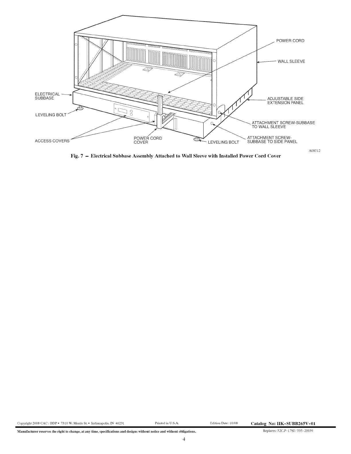
Step 12 -- Attach receptacle access cover to subbase with
2 black screws provided, capturing end of power cord cover.
See Fig. 4. See Fig. 7 for completed assembly.
Step 13 -- Replace front panel and restore power to unit.
POWER CORD
/PTAC UNIT UNIT
BASEPAN
SUBBASE
/
/
POWER RECEPTACLE SCREWS POWER CORD
CORD ACCESS NOTCH
COVER COVER (ON SUBBASE)
A08511
Fig. 6 - Location of Power Cord Cover on Basepan
POWER CORD
ELECTRICAL
SUBBASE
LEVELING BOLT
POWER CORD
ACCESS COVERS COVER
WALL SLEEVE
__ ADJUSTABLE SIDE
EXTENSION PANEL
ATTACHMENT SCREW-SUBBASE
TO WALL SLEEVE
ATTACHMENT SCREW-
LEVELING BOLT SUBBASE TO SIDE PANEL
Fig. 7 - Electrical Subbase Assembly Attached to Wall Sleeve with Installed Power Cord Cover
A08512
Copyright 2008 CA( /BDP ° 7310 W. MorrisSt. ° hldianapolis. IN 46231 Printed in U.S.A.
Manufacturer reserves the right to change_ at any time_ specifications and designs without notice and without obligations.
4
Edition Date: 10/08 Catalog No: IIK-SUBB265V-01
Replaces: 52(.P 17S1/535 20039
