CARRIER Package Units(both Units Combined) Manual L0912106
User Manual: CARRIER CARRIER Package Units(both units combined) Manual CARRIER Package Units(both units combined) Owner's Manual, CARRIER Package Units(both units combined) installation guides
Open the PDF directly: View PDF ![]() .
.
Page Count: 44
Irn ®
to the Expertg_
Installation Instructions
NOTE: Read the entire instruction manual before starting
the installation
TABLE OF CONTENTS
SAFETY CONSIDERATIONS .................... 1
INSTALLATION ............................... 5
Step 1 - Plan for Unit Location .................. 5
Step 2 - Plan for Sequence of Unit Installation ...... 6
Step 3 - Inspect Unit ........................... 6
Step 4 - Provide Unit Support ................... 6
Step 5 - Field Fabricate Ductwork ................ 8
Step 6 - Rig and Place Unit ..................... 8
Step 7 - Convert to Horizontal and Connect
Ductwork ............................ 9
Step 8 - Install Outside Air Hood ................ 9
Step 9 - Install Flue Hood ..................... 10
Step 10 - Install Gas Piping .................... 11
Step 11 - Install External Condensate Trap
and Line ........................... 13
Step 12 - Make Electrical Connections ........... 13
Step 13 - Humidi-MiZer TM--
Space RH Controller .................. 37
Step 14 - Adjust Factory-Installed Options ........ 43
Step 15 - Install Accessories ................... 43
SAFETY CONSIDERATIONS
Improper installation, adjustment, alteration, service,
maintenance, or use can cause explosion, fire, electrical
shock or other conditions which may cause personal
injury or property damage. Consult a qualified installer,
service agency, or your distributor or branch for
information or assistance. The qualified installer or
agency must use factory-authorized kits or accessories
when modifying this product. Refer to the individual
instructions packaged with the kits or accessories when
installing.
Follow all safety codes. Wear safety glasses and work
gloves. Use quenching cloths for brazing operations and
have a fire extinguisher available. Read these instructions
thoroughly and follow all warnings or cautions attached to
the unit. Consult local building codes and appropriate
national electrical codes (in USA, ANSI/NFPA70,
National Electrical Code (NEC); in Canada, CSA C22.1)
for special requirements.
It is important to recognize safety information. This is the
safety-alert symbol A'x. When you see this symbol on the
unit and in instructions or manuals, be alert to the
potential for personal injury.
Understand the signal words DANGER, WARNING,
CAUTION, and NOTE. These words are used with the
safety-alert symbol. DANGER identifies the most serious
hazards which will result in severe personal injury or
death. WARNING signifies hazards which could result in
personal injury or death. CAUTION is used to identify
unsafe practices, which may result in minor personal
injury or product and property damage. NOTE is used to
highlight suggestions which will result in enhanced
installation, reliability, or operation.
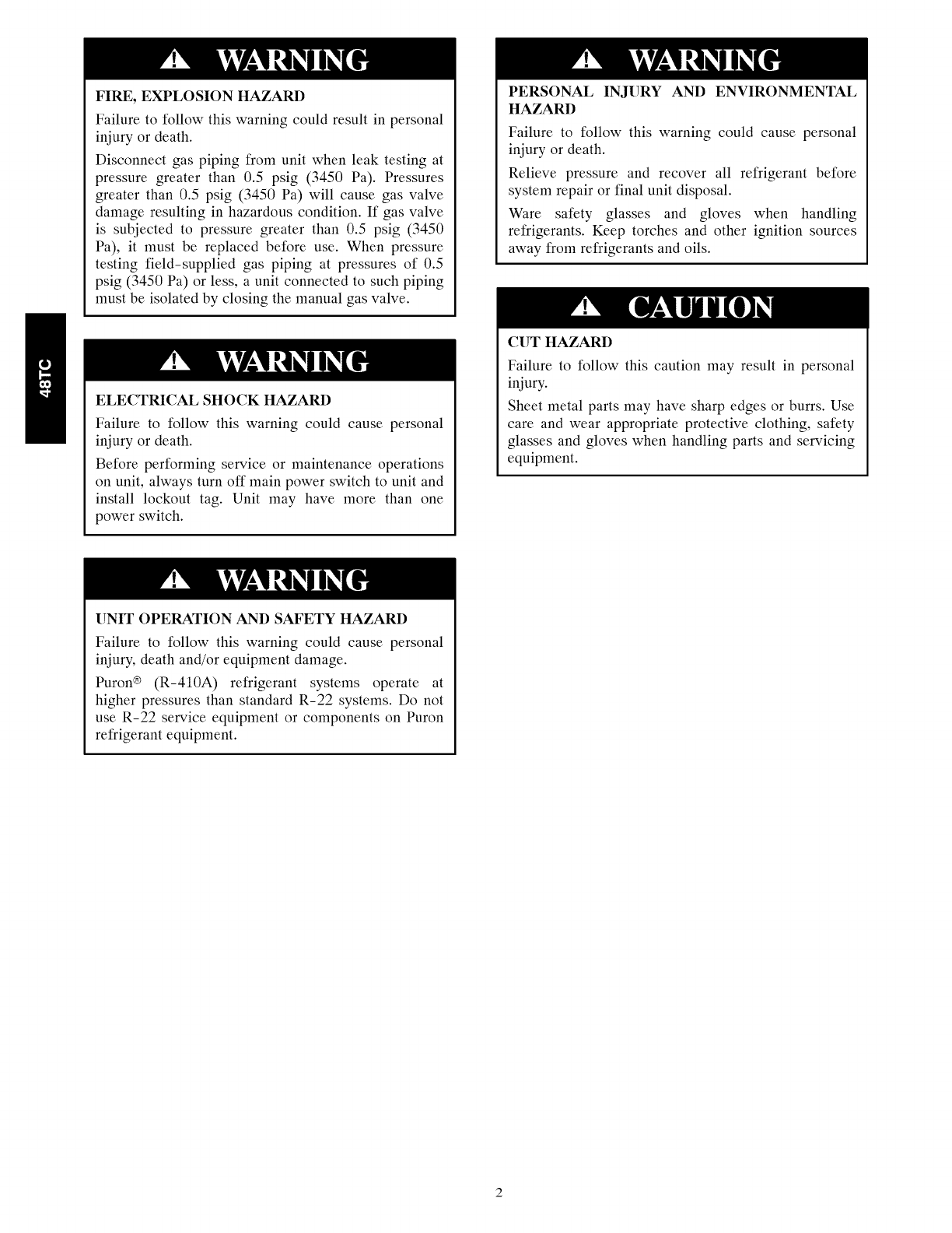
FIRE,EXPLOSIONHAZARD
Failuretofollowthiswarningcouldresultinpersonal
injuryordeath.
Disconnectgaspipingfromunitwhenleaktestingat
pressuregreaterthan0.5psig(3450Pa).Pressures
greaterthan0.5psig(3450Pa)will causegasvalve
damageresultinginhazardouscondition.If gasvalve
is subjectedto pressuregreaterthan0.5psig(3450
Pa),it mustbereplacedbeforeuse.Whenpressure
testingfield-suppliedgaspipingat pressuresof 0.5
psig(3450Pa)orless,aunitconnectedto suchpiping
mustbeisolatedbyclosingthemanualgasvalve.
ELECTRICALSHOCKHAZARD
Failure to follow this warning could cause personal
injury or death.
Before performing service or maintenance operations
on unit, always turn oft" main power switch to unit and
install lockout tag. Unit may have more than one
power switch.
PERSONAL INJURY AND ENVIRONMENTAL
HAZARD
Failure to follow this warning could cause personal
injury or death.
Relieve pressure and recover all refrigerant before
system repair or final unit disposal.
Ware safety glasses and gloves when handling
refrigerants. Keep torches and other ignition sources
away from refrigerants and oils.
CUT HAZARD
Failure to follow this caution may result in personal
injury.
Sheet metal parts may have sharp edges or burrs. Use
care and wear appropriate protective clothing, safety
glasses and gloves when handling parts and servicing
equipment.
UNIT OPERATION AND SAFETY HAZARD
Failure to follow this warning could cause personal
injury, death and/or equipment damage.
Puron ® (R-410A) refrigerant systems operate at
higher pressures than standard R-22 systems. Do not
use R-22 service equipment or components on Puron
refrigerant equipment.
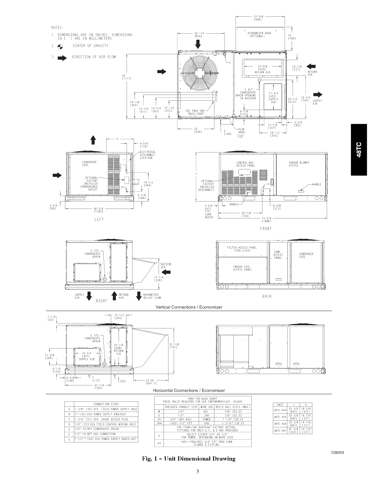
NOTES:
1 DIMENSIONS ARE IN INCHES, DIMENSIONS
IN [ ] ARE IN MILLIMETERS
2 _ CENTER OF GRAVITY
3 _ DIRECTION OF AIR FLOW
44
[111_]
18 f
[41
16 !/8 14 1/4 12 //4
[411] [563] [512]
N _L 4 B/8
/[1/8]
fELECTRICAL
DISCONNECT
32 1/4
[818]
Lc
,Z
[lO0]
53 3/8
E848]
ECONOMIZER HOOD
(OPTIONAL}
ik RE'TURN AIR
2B 5/8
[652]
E ALT l_iil l
CONDENSATE
GRAIN OPENING
IN 8ASERAN
6 1/4
I 12 1/8
_FLUE [307]
HOOD _ 18 !/2
TOP E_Yo]
f
16
[406]
10 718
[277] _
RETURN
AIR
26 //2 [747] SUPPLY
[B71B]IAR
B 3/B
[85]
B 3/4
[95]
[1!87]
LEFT
CONTROL BOX INDOOR 8LOWER
ACCESS PANEL ACCESS
DISCONNEcTOPTIONAL--'__FACTORY
INSTALLED
_oo _ __ _: "
Bs/B-- I_ HANDLE_ LBs,8
[67] [213]
TYP
CURB _ 30 1/8
[1888]
o6
FRONT
AIR RIGHT AIR
BAROMETRICRELIEF FLOW
FILTER ACCESS PANEL
(TOOL LESS} COMP
ACCESS CONDENSER
COIL
PANEL
INDOOR COIL
ACCESS PANEL
BACK
Vertical Connections /Economizer
!1 B/8
[289]
B //8
[155]
t
E1 E1
_oo " :_ _ 'DO
Horizontal Connections /Economizer
CONNECTION SIZES
A 3/8 II [55] DIA FIELD POWER SUPPLY HOLE
8 2" [BO] BIA POWER SUPPLY NROCNOUT
C 3/4" [B1] DIA GAUGE ACCESS PLUG
D7/811 [22] DIA FIEL8 CONTROL WIRING HOLE
E 314" 14 NPT cONDENSATE DRAIN
F liB" 14 NPT GAS CONNECTION
8 B llZ II [64] 81A POWER sUPPLY NNOCK OUT
THRU THE BASE CHART
THESE HOLES REQUIRED FOR USE CRBTMPWROOIAOl, OOBAOl
THREADED CONDUIT SIZE WINE USE REQ'D HOLE SIZES (MAX)
lIB II A_C 7/8" [22Z]
1/211 24V //811 [222]
Y¢ 3/411 (OO/,OO3) POWER / !/8" [284]
Z@* {003) ]12 II FPT GAS 1 3116 II [300]
FOR "THRU THE BASEPAN" FACTORY OPTION,
FITTINGS FOR ONLY ×,Y, & Z ARE PROVIDE8
SELECT EITHER B/4" OR I/2"
÷ FOR POWER, DEPENDING OR WIRE SIZE
÷÷ (OOl} PROVIGES 3/4" FPT THRU CURB
FLANGE & FITTIRG
UNIT !8 %/8
48TC AB4 [B47] [472]
_urcA0__L?,';,%18
Fig. 11Unit Dimensional Drawing
C09303
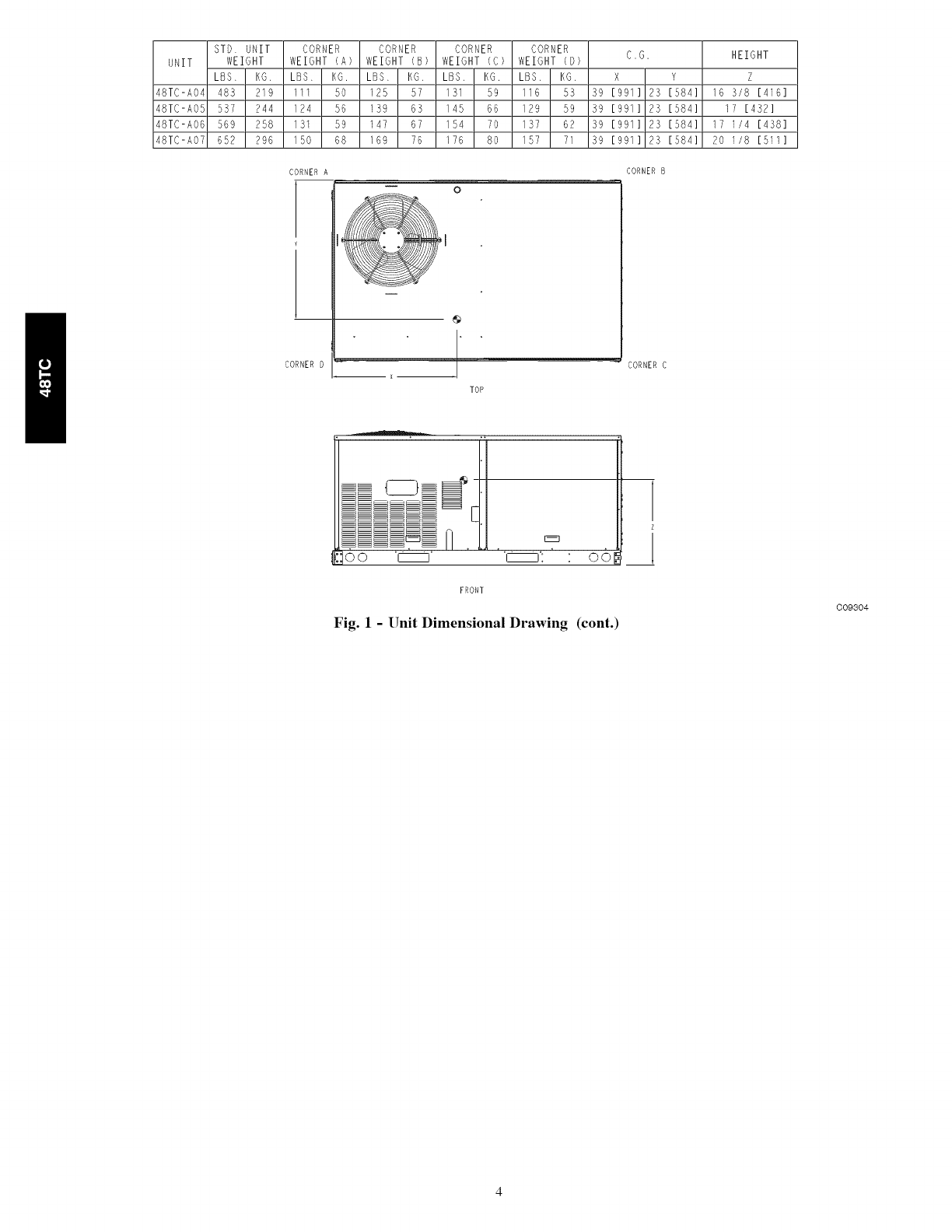
STD UNIT CORNER CORNER CORNER CORNER C.G. HEIGHT
UNIT WEIGHT WEIGHT (A) WEIGHT (B) WEIGHT (C) WEIGHT (D)
LBS. KG, LBS. KO. LBS. KG. LBS, KG. LBS, KG. X Y Z
48TC-A04 483 219 111 50 125 57 131 59 116 53 59 [991] 25 [584] 16 3/8 [416]
48TC-AO5 557 244 124 56 I39 63 145 66 129 59 59 [991] 23 [584] 17 [432]
48TC-A06 569 258 131 59 147 67 154 70 137 62 59 [991] 25 [584] 17 1/4 [458]
48TC-A07 652 296 150 68 169 76 176 80 157 71 39 [991] 23 [584] 20 1/8 [511]
CORNER A CORNERB
CORNERO
L@,
0
@
" CORNERC
× --
TOP
,:]oo
E_
FRONT
Fig. 1-Unit Dimensional Drawing (cont.)
1
i
C09304
INSTALLATION
Jobsite Survey
Complete the following checks before installation.
1. Consult local building codes and the NEC (National
Electrical Code) ANSI/NFPA 70 for special installa-
tion requirements.
2. Determine unit location (from project plans) or select
unit location.
3. Check for possible overhead obstructions which may
interfere with unit lifting or rigging.
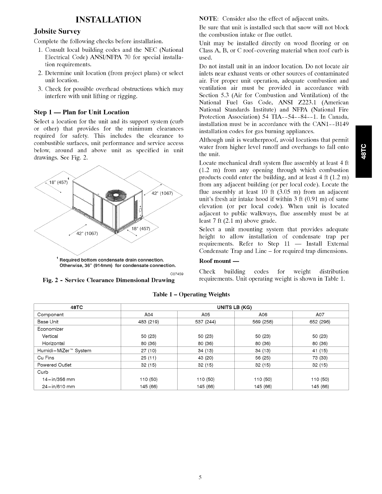
Step 1 -- Plan for Unit Location
Select a location for the unit and its support system (curb
or other) that provides for the minimum clearances
required for safety. This includes the clearance to
combustible surfaces, unit performance and service access
below, around and above unit as specified in unit
drawings. See Fig. 2.
<
_42" (1067) J
J
_. jJ
.//
1 Required bottom condensate drain connection.
Otherwise, 36" (914mm) for condensate connection.
C07459
Fig. 2 - Service Clearance Dimensional Drawing
NOTE: Consider also the effect of adjacent units.
Be sure that unit is installed such that snow will not block
the combustion intake or flue outlet.
Unit may be installed directly on wood flooring or on
Class A, B, or C roof-covering material when roof curb is
used.
Do not install unit in an indoor location. Do not locate air
inlets near exhaust vents or other sources of contaminated
air. For proper unit operation, adequate combustion and
ventilation air must be provided in accordance with
Section 5.3 (Air for Combustion and Ventilation) of the
National Fuel Gas Code, ANSI Z223.1 (American
National Standards Institute) and NFPA (National Fire
Protection Association) 54 TIA--54--84--1. In Canada,
installation must be in accordance with the CANl--B149
installation codes for gas burning appliances.
Although unit is weatherproof, avoid locations that permit
water from higher level runoff and overhangs to fall onto
the unit.
Locate mechanical draft system flue assembly at least 4 ft
(1.2 m) from any opening through which combustion
products could enter the building, and at least 4 ft (1.2 m)
from any adjacent building (or per local code). Locate the
flue assembly at least 10 ft (3.05 m) from an adjacent
unit's fresh air intake hood if within 3 ft (0.91 m) of same
elevation (or per local code). When unit is located
adjacent to public walkways, flue assembly must be at
least 7 ft (2.1 m) above grade.
Select a unit mounting system that provides adequate
height to allow installation of condensate trap per
requirements. Refer to Step 11 -- Install External
Condensate Trap and Line - for required trap dimensions.
Roof mount --
Check building codes for weight distribution
requirements. Unit operating weight is shown in Table 1.
Table 1-Operating Weights
48TC UNITS LB (KG)
Component A04 A05 A08 A07
Base Unit 483 (219) 537 (244) 569 (258) 852 (298)
Economizer
Vertical 50 (23) 50 (23) 50 (23) 50 (23)
Horizontal 80 (38) 80 (38) 80 (38) 80 (38)
Humidi-MiZer T_System 27 (10) 34 (13) 34 (13) 41 (15)
Cu Fins 25 (11) 43 (20) 56 (25) 73 (33)
Powered Outlet 32 (15) 32 (15) 32 (15) 32 (15)
Curb
14-in/356 mm 110 (50) 110 (50) 110 (50) 110 (50)
24-in/610 mm 145 (66) 145 (66) 145 (66) 145 (66)
Step 2 1 Plan for Sequence of Unit Installation
The support method used for this unit will dictate different
sequences for the steps of unit installation. For example,
on curb-mounted units, some accessories must be
installed on the unit before the unit is placed on the curb.
Review the following for recommended sequences for
installation steps.
Curb-mounted installation i
Install curb
Install field-fabricated ductwork inside curb
Install accessory thru-base service connection package
(affects curb and unit) (refer to accessory installation
instructions for details)
Prepare bottom condensate drain connection to suit
planned condensate line routing (refer to Step 11 for
details)
Rig and place unit
Install outdoor air hood
Install flue hood
Install gas piping
Install condensate line trap and piping
Make electrical connections
Install other accessories
Pad-mounted installation i
Prepare pad and unit supports
Check and tighten the bottom condensate
connection plug
Rig and place unit
Convert unit to side duct connection arrangement
Install field-fabricated ductwork at unit duct openings
Install outdoor air hood
Install flue hood
Install gas piping
Install condensate line trap and piping
Make electrical connections
Install other accessories
drain
Frame-mounted installation i
Frame-mounted applications generally follow the
sequence for a curb installation. Adapt as required to
suit specific installation plan.
Step 3 1 Inspect unit
Inspect unit for transportation damage. File any claim
with transportation agency.
Confirm before installation of unit that voltage, amperage
and circuit protection requirements listed on unit data
plate agree with power supply provided.
Step 41Provide Unit Support
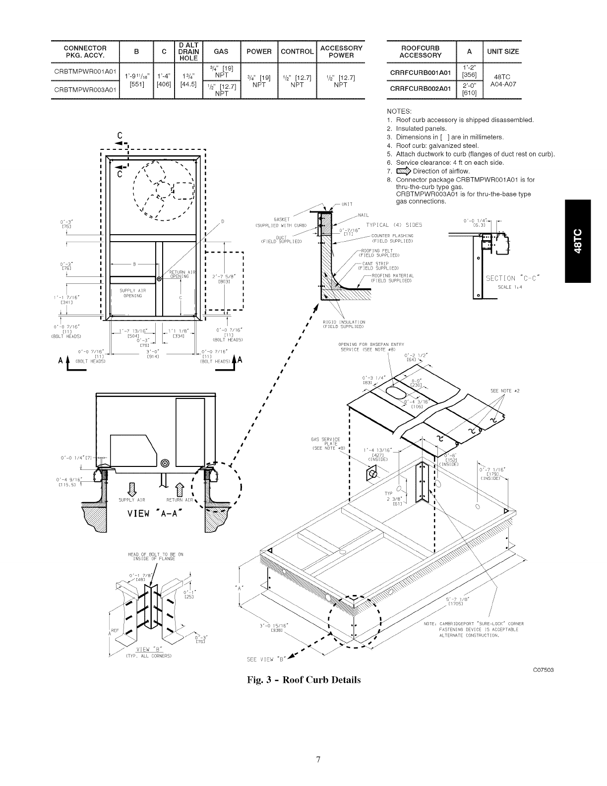
Roof Curb Mount i
Accessory roof curb details and dimensions are shown in
Fig. 3. Assemble and install accessory roof curb in
accordance with instructions shipped with the curb.
NOTE: The gasketing of the unit to the roof curb is
critical for a watertight seal. Install gasket supplied with
the roof curb as shown in Fig. 3. Improperly applied
gasket can also result in air leaks and poor unit
performance.
Curb should be level. This is necessary for unit drain to
function properly. Unit leveling tolerances are show in
Fig. 4. Refer to Accessory Roof Curb Installation
Instructions for additional information as required.
Install insulation, cant strips, roofing felt, and counter
flashing as shown. Ductwork ntust be attached to curb and
not to the unit. The accessory thru-the-base power and
gas connection package must be installed before the unit
is set on the roof curb. If field-installed thru-the-roof
curb gas connections are desired, use factory-supplied
1/2-in. pipe coupling and gas plate assembly to mount the
thru-the-roof curb connection to the roof curb. Gas
connections and power connections to the unit must be
field installed after the unit is installed on the roof curb.
If electric and control wiring is to be routed through the
basepan, attach the accessory thru-the-base service
connections to the basepan in accordance with the
accessory installation instructions.
Slab Mount (Horizontal Units Only) i
Provide a level concrete slab that extends a minimum of
6 in. (150 mm) beyond unit cabinet. Install a gravel apron
in front of condenser coil air inlet to prevent grass and
foliage from obstructing airflow.
NOTE: Horizontal units may be installed on a roof curb
if required.
Alternate Unit Support (In Lieu of Curb or Slab
Mount) i
A non-combustible sleeper rail can be used in the unit
curb support area. If sleeper rails cannot be used, support
the long sides of the unit with a minimum of 3 equally
spaced 4-in. x 4-in. (102 mm x 102 mm) pads on each
side.
CONNECTOR
PKG. ACCY.
CRBTMPWROO1A01
CRBTMPWROO3A01
D ALT
B C DRAIN
HOLE
1'-9W16" 1'-4" lS//'
[551] [406] [44.5]
GAS
3/4"[_9}
NPT
1/2" [12.7]
NPT
POWER
3//, [19]
NPT
CONTROL
1/2" [12.7]
NPT
ACCESSORY
POWER
1_,, [12.7]
NPT
ROOFCURB I A I UNIT SIZE
ACCESSORY
CRRFCURB001A01 48TC
2'-0"
CRRFCURB002A01 _ A04-A07
o" B"
[TB]
0'3"
[78]
1" I 7/18" I
[34/] I
T _
O" 0 7/16"
[/1]
(BOLT HEADS)
O" 0 7/16"
LT [11]
A HEAl)}
C
_II "1
I
C#\ j %%
! \ _)4- \ I --- "11
I I _ ii
I
\\ #_#
\1 t. # #
SUPPLY AIR l
OPENING
1" 7 13/16" 1"1 1/8"
EBo_o_;+
I
I
I
I
I
I
I
I
I
I
If
i/
I
I- ..... q
I
I
I
I 2" 7 518"
I [8
I
I
I
I
' F
O' 0 7/+B"
E++]
(BOLT HEM)S)
O' 0 7//6"
++E+U iA
(BOLT
O' 0 I/4"[?]
8
SUPPLY AIR
@
RETURN AIR _.
VIEW "A-A"
#
#
NOTES:
1. Roof curb accessory is shipped disassembled.
2. Insulated panels.
3. Dimensions in [ ] are in millimeters.
4. Roof curb: galvanized steel.
5. Attach ductwork to curb (flanges of duct rest on curb).
6. Service clearance: 4 ft on each side.
Direction of airflow.
7.
8. Connector package CRBTMPWROO1A01 is for
thru-the-curb type gas.
CRBTMPWROO3A01 is for thru-the-base type
gas connections.
TYPICAL (4) S[OES
o' 7/+B _
R[D]D ]NSbLATION
(F]ELD SUPPLIED)
OPENING FOR BABEPAN ENTRY
SERVICE (SEE NOTE #8)
/ O" 2112"
//4 =
1' 4 13/15"
_ [427]
HEAD OF BOLT TO BE ON
INSIDE OF FLANGE
)
Fig. 3 - Roof Curb Details
S' ?SIS" /
[I 705]
NOTE= CAMBR]DGEPORT +SURE LOCK" CORNER
FASTENING DEV]CE IB ACCEPTABLE
ALTERNATE CONSTRUCTION.
C07503
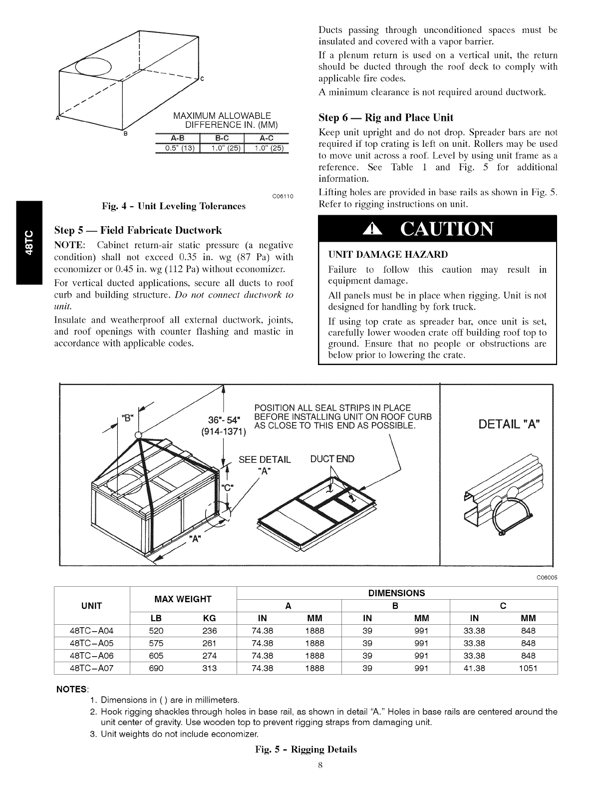
c
UM ALLOWABLE
-"'_--_ DIFFERENCE IN. (MM)
8A-B I B-c [ A-C
0.5" (13) J_ 1.0" (25) [ 1.0" (25)
Fig. 4 - Unit Leveling Tolerances
C06110
Step 5 -- Field Fabricate Ductwork
NOTE: Cabinet return-air static pressure (a negative
condition) shall not exceed 0.35 in. wg (87 Pa) with
economizer or 0.45 in. wg (112 Pa) without economizer.
For vertical ducted applications, secure all ducts to roof
curb and building structure. Do not connect ductwork to
unit.
Insulate and weatherproof all external ductwork, joints,
and roof openings with counter flashing and mastic in
accordance with applicable codes.
Ducts passing through unconditioned spaces must be
insulated and covered with a vapor barrier.
If a plenum return is used on a vertical unit, the return
should be ducted through the roof deck to comply with
applicable fire codes.
A minimum clearance is not required around ductwork.
Step 6-- Rig and Place Unit
Keep unit upright and do not drop. Spreader bars are not
required if top crating is left on unit. Rollers may be used
to move unit across a roof. Level by using unit frame as a
reference. See Table 1 and Fig. 5 for additional
information.
Lifting holes are provided in base rails as shown in Fig. 5.
Refer to rigging instructions on unit.
UNIT DAMAGE HAZARD
Failure to follow this caution may result in
equipment damage.
All panels must be in place when rigging. Unit is not
designed for handling by fork truck.
If using top crate as spreader bar, once unit is set,
carefully lower wooden crate off building roof top to
ground. Ensure that no people or obstructions are
below prior to lowering the crate.
36"- 54"
(914-1371)
SEE DETAIL
POSITION ALL SEAL STRIPS IN PLACE
BEFORE INSTALLING UNIT ON ROOF CURB
AS CLOSE TO THIS END AS POSSIBLE.
"A"
<
DETAIL "A"
UNIT MAX WEIGHT
LB KG IN IN
48TC-A04 520 236 74.38 33.38
48TC-A05 575 261 74.38 33.38
48TC-A06 605 274 74.38 33.38
48TC-A07 690 313 74.38 41.38
A
IVllVl
1888
1888
1888
1888
DIMENSIONS
B
IN MM
39 991
39 991
39 991
39 991
C06005
C
MM
848
848
848
1051
NOTES:
1. Dimensions in ( ) are in millimeters.
2. Hook rigging shackles through holes in base rail, as shown in detail "A." Holes in base rails are centered around the
unit center of gravity. Use wooden top to prevent rigging straps from damaging unit.
3. Unit weights do not include economizer.
Fig. 5- Rigging Details
Before setting the unit onto the curb, recheck gasketing on
curb.
Positioning on Curb --
Position unit on roof curb so that the following clearances
are maintained: 1/4 in. (6.4 ram) clearance between the
roof curb and the base rail inside the front and rear, 0.0 in.
clearance between the roof curb and the base rail inside on
the duct end of the unit. This will result in the distance
between the roof curb and the base rail inside on the
condenser end of the unit being approximately equal to
Fig. 3, section C-C.
Although unit is weatherproof, guard against water from
higher level runoff and overhangs.
UNIT DAMAGE HAZARD
Failure to follow this caution may result in
equipment damage.
All panels must be in place when rigging. Unit is not
designed for handling by fork truck.
Flue vent discharge must have a minimum horizontal
clearance of 4 f! (1220 mm) from electric and gas meters,
gas regulators; and gas relief equipment. Minimum
distance between unit and other electrically live parts" is
48 inches (1220 mm).
Flue gas can deteriorate building materials. Orient unit
such that flue gas will not affect building materials.
Locate mechanical draft system flue assembly at least 48
in. (1220 ram) from an adjacent building or combustible
material.
NOTE: Installation of accessory flue discharge deflector
kit will reduce the minimum clearance to combustible
material to 18 in. (460 ram).
After unit is in position, remove rigging skids and
shipping materials.
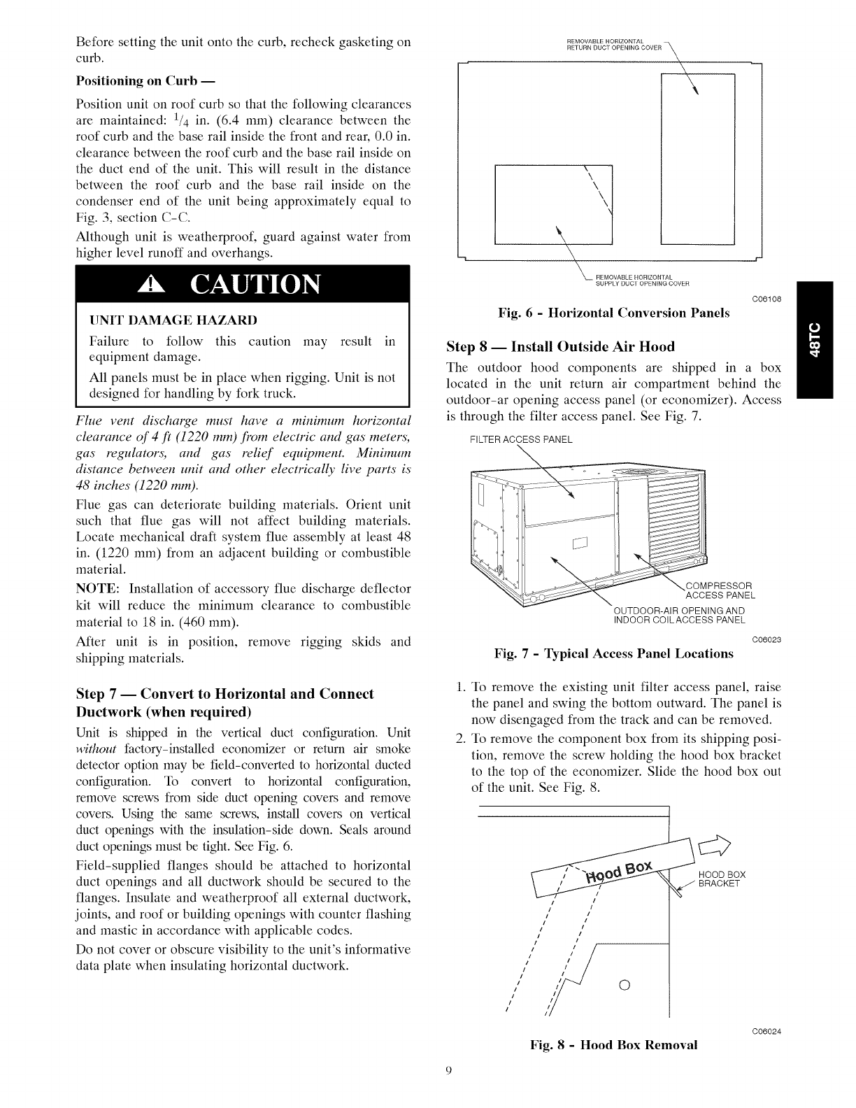
Step 7 -- Convert to Horizontal and Connect
Ductwork (when required)
Unit is shipped in the vertical duct configuration. Unit
without factory-installed economizer or return air smoke
detector option may be field-converted to horizontal ducted
configuration. To convert to horizontal configuration,
remove screws from side duct opening covers and remove
covers. Using the same screws, install covers on vertical
duct openings with the insulation-side down. Seals around
duct openings must be tight. See Fig. 6.
Field-supplied flanges should be attached to horizontal
duct openings and all ductwork should be secured to the
flanges. Insulate and weatherproof all external ductwork,
joints, and roof or building openings with counter flashing
and mastic in accordance with applicable codes.
Do not cover or obscure visibility to the unit's informative
data plate when insulating horizontal ductwork.
\\
\\
\\
_M_ REMOVABLE ItORIZONTAL
SUPPLY DUCI OPENING COVER
Fig. 6 -Horizontal Conversion Panels
C06108
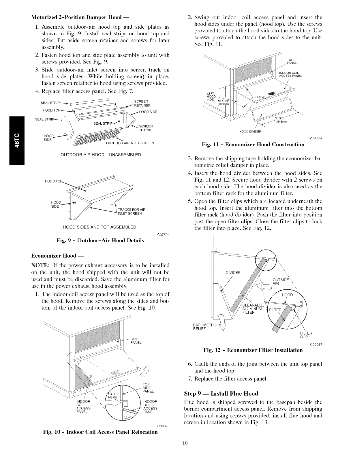
Step 8-- Install Outside Air Hood
The outdoor hood components are shipped in a box
located in the unit return air compartment behind the
outdoor-ar opening access panel (or economizer). Access
is through the filter access panel. See Fig. 7.
FILTER ACCESS PANEL
COMPRESSOR
ACCESS PANEL
OUTDOOR-AIR OPENING AND
INDOOR COILACCESS PANEL
C06023
Fig. 7-Typical Access Panel Locations
1. To remove the existing unit filter access panel, raise
the panel and swing the bottom outward. The panel is
now disengaged from the track and can be removed.
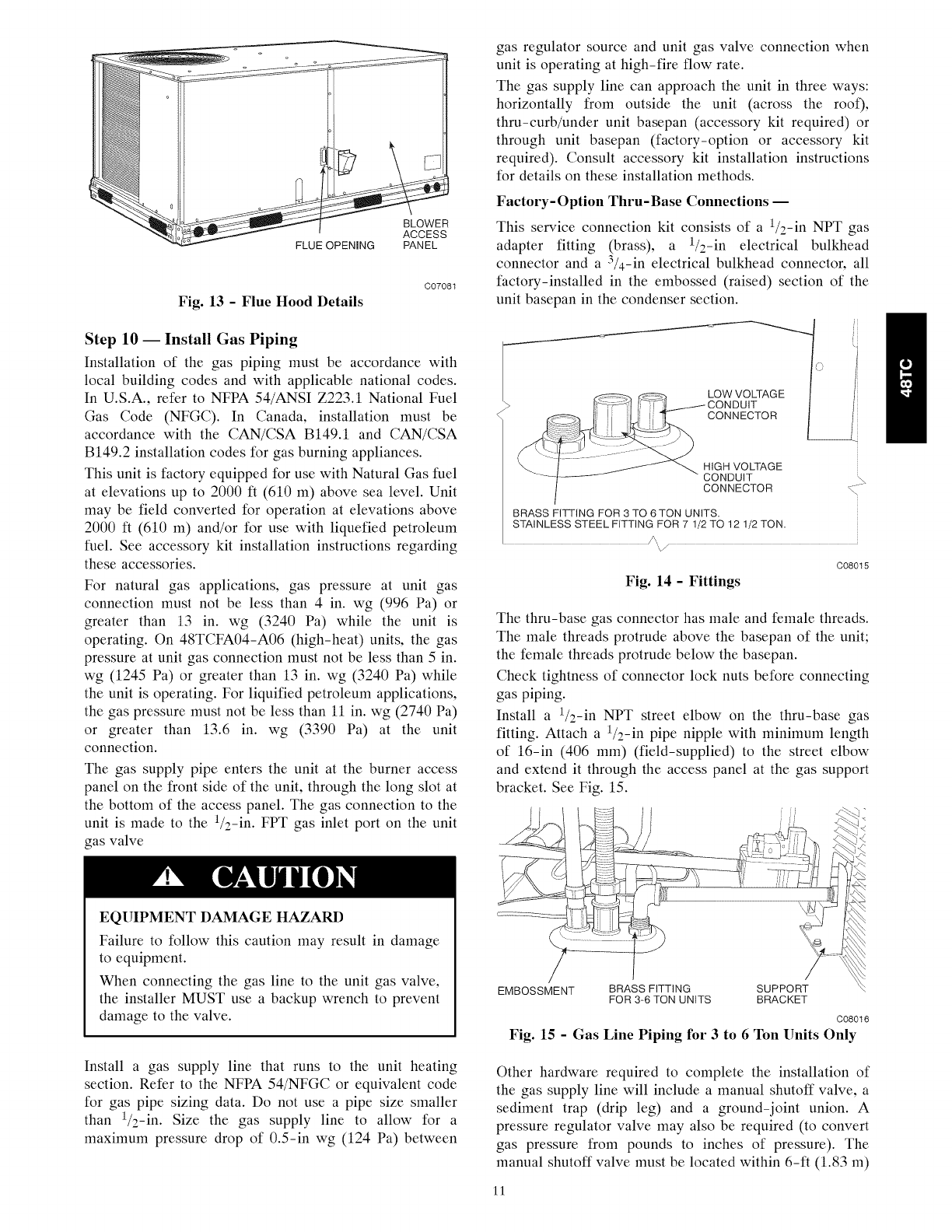
2. To remove the component box from its shipping posi-
tion, remove the screw holding the hood box bracket
to the top of the economizer. Slide the hood box out
of the unit. See Fig. 8.
HOOD BOX
BRACKET
/
/
/
/
iI
i I
iI
ii
i I
iI
I
II
/I
i /
I I
0
Fig. 8-Hood Box Removal
C06024
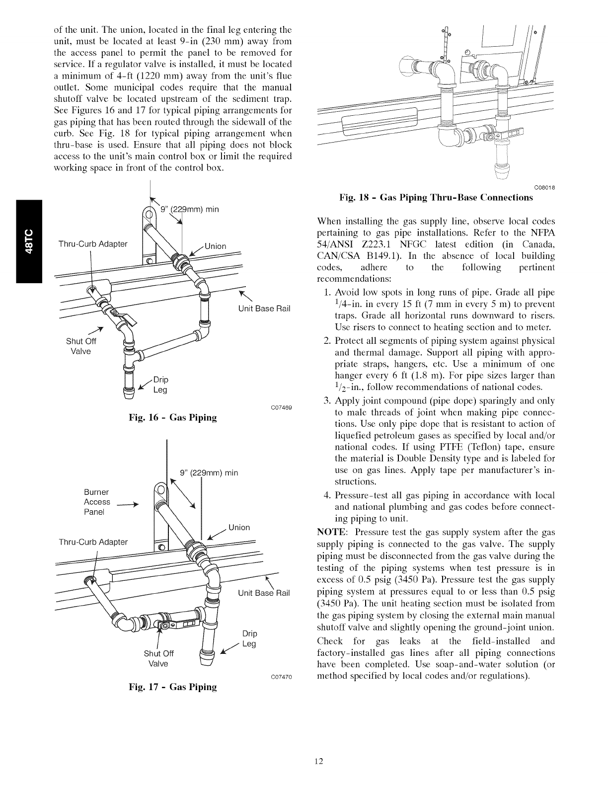
Motorized 2-Position Damper Hood i
1. Assemble outdoor-air hood top and side plates as
shown in Fig. 9. Install seal strips on hood top and
sides. Put aside screen retainer and screws for later
assembly.
2. Fasten hood top and side plate assembly to unit with
screws provided. See Fig. 9.
3. Slide outdoor-air inlet screen into screen track on
hood side plates. While holding screen) in place,
fasten screen retainer to hood using screws provided.
4. Replace filter access panel. See Fig. 7.
SEAL STRIP"-,--,q_ _ SCREEN
RETAINER
HOOD TOP _ _,,,,.,4.,,,,._HOOD SIDE
SEAL STRIP_ _ I _) SCREEN
Ull)j TRACKS
HOO D,,,.,..-,--,-""T_ _ J
S,OE //_
OUTDOOR AIR INLET SCREEN
OUTDOOR-AIR HOOD UNASSEMBLED
HOOD
SIDE
TRACKS FOR AIR
;REEN
HOOD SIDES AND TOP ASSEMBLED
Fig. 9 - Outdoor-Air Hood Details
C07504
2. Swing out indoor coil access panel and insert the
hood sides under the panel (hood top). Use the screws
provided to attach the hood sides to the hood top. Use
screws provided to attach the hood sides to the unit.
See Fig. 11.
33/8"
HOOD DIVIDER
C06026
Fig. 11 - Economizer Hood Construction
3. Remove the shipping tape holding the economizer ba-
rometric relief damper in place.
4. Insert the hood divider between the hood sides. See
Fig. 11 and 12. Secure hood divider with 2 screws on
each hood side. The hood divider is also used as the
bottom filter rack for the aluminum filter.
5. Open the filter clips which are located underneath the
hood top. Insert the aluminum filter into the bottom
filter rack (hood divider). Push the filter into position
past the open filter clips. Close the filter clips to lock
the filter into place. See Fig. 12.
Economizer Hood i
NOTE: If the power exhaust accessory is to be installed
on the unit, the hood shipped with the unit will not be
used and must be discarded. Save the aluminum filter for
use in the power exhaust hood assembly.
1. The indoor coil access panel will be used as the top of
the hood. Remove the screws along the sides and bot-
tom of the indoor coil access panel. See Fig. 10. ALUMINUM
FILTER
SiDE
PANEL
iNDOOR
COIL
ACCESS
PANEL
TOP
PANEL
INDOOR
COiL
PANEL
C06025
Fig. 10 - Indoor Coil Access Panel Relocation
BAROMETRIC
RELIEF
FILTER
CLIP
C06027
Fig. 12 - Economizer Filter Installation
6. Caulk the ends of the joint between the unit top panel
and the hood top.
7. Replace the filter access panel.
Step 9 1 Install Flue Hood
Flue hood is shipped screwed to the basepan beside the
burner compartment access panel. Remove from shipping
location and using screws provided, install flue hood and
screen in location shown in Fig. 13.
10
FLUE OPENING
BLOWER
ACCESS
PANEL
Fig. 13 - Flue Hood Details
C07081
Step 10 -- Install Gas Piping
Installation of the gas piping must be accordance with
local building codes and with applicable national codes.
In U.S.A., refer to NFPA 54/ANSI Z223.1 National Fuel
Gas Code (NFGC). In Canada, installation must be
accordance with the CAN/CSA B149.1 and CAN/CSA
B149.2 installation codes for gas burning appliances.
This unit is factory equipped for use with Natural Gas fuel
at elevations up to 2000 ft (610 m) above sea level. Unit
may be field converted for operation at elevations above
2000 ft (610 m) and/or for use with liquefied petroleum
fuel. See accessory kit installation instructions regarding
these accessories.
For natural gas applications, gas pressure at unit gas
connection must not be less than 4 in. wg (996 Pa) or
greater than 13 in. wg (3240 Pa) while the unit is
operating. On 48TCFA04-A06 (high-heat) units, the gas
pressure at unit gas connection must not be less than 5 in.
wg (1245 Pa) or greater than 13 in. wg (3240 Pa) while
the unit is operating. For liquified petroleum applications,
the gas pressure must not be less than 11 in. wg (2740 Pa)
or greater than 13.6 in. wg (3390 Pa) at the unit
connection.
The gas supply pipe enters the unit at the burner access
panel on the front side of the unit, through the long slot at
the bottom of the access panel. The gas connection to the
unit is made to the 1/2-in. FPT gas inlet port on the unit
gas valve
EQUIPMENT DAMAGE HAZARD
Failure to follow this caution may result in damage
to equipment.
When connecting the gas line to the unit gas valve,
the installer MUST use a backup wrench to prevent
damage to the valve.
Install a gas supply line that runs to the unit heating
section. Refer to the NFPA 54/NFGC or equivalent code
for gas pipe sizing data. Do not use a pipe size smaller
than 1/2-in. Size the gas supply line to allow for a
maximum pressure drop of 0.5-in wg (124 Pa) between
gas regulator source and unit gas valve connection when
unit is operating at high-fire flow rate.
The gas supply line can approach the unit in three ways:
horizontally from outside the unit (across the roof),
thru-curb/under unit basepan (accessory kit required) or
through unit basepan (factory-option or accessory kit
required). Consult accessory kit installation instructions
for details on these installation methods.
Factory- Option Thru-Base Connections --
This service connection kit consists of a 1/2-in NPT gas
adapter fitting (brass), a 1/2-in electrical bulkhead
connector and a 3/4-in electrical bulkhead connector, all
factory-installed in the embossed (raised) section of the
unit basepan in the condenser section.
LOW VOLTAGE
CONNECTOR
HIGH VOLTAGE
CONDUIT
CONNECTOR
BRASS FITTING FOR 3 TO 6 TON UNITS.
STAINLESS STEEL FITTING FOR 7 1/2 TO 12 1/2 TON.
C08015
Fig. 14 - Fittings
The thru-base gas connector has male and female threads.
The male threads protrude above the basepan of the unit;
the female threads protrude below the basepan.
Check tightness of connector lock nuts before connecting
gas piping.
Install a 1/2-in NPT street elbow on the thru-base gas
fitting. Attach a 1/2-in pipe nipple with minimum length
of 16-in (406 mm) (field-supplied) to the street elbow
and extend it through the access panel at the gas support
bracket. See Fig. 15.
EMBOSSMENT BRASS FITTING SUPPORT
FOR 3-6 TON UNITS BRACKET
C08016
Fig. 15 - Gas Line Piping for 3 to 6 Ton Units Only
Other hardware required to complete the installation of
the gas supply line will include a manual shutoff valve, a
sediment trap (drip leg) and a ground-joint union. A
pressure regulator valve may also be required (to convert
gas pressure from pounds to inches of pressure). The
manual shutoff valve must be located within 6-ft (1.83 m)
11
of the unit. The union, located in the final leg entering the
unit, must be located at least 9-in (230 mm) away from
the access panel to permit the panel to be removed for
service. If a regulator valve is installed, it must be located
a minimum of 4-fl (1220 mm) away from the unit's flue
outlet. Some municipal codes require that the manual
shutoff valve be located upstream of the sediment trap.
See Figures 16 and 17 for typical piping arrangements for
gas piping that has been routed through the sidewall of the
curb. See Fig. 18 for typical piping arrangement when
thru-base is used. Ensure that all piping does not block
access to the unit's main control box or limit the required
working space in front of the control box.
_mm) rain
Thru-Curb Adapter Jnion
Shut Off
Valve
\
Unit Base Rail
_/Drip
Leg
Fig. 16 - Gas Piping
C07469
Burner
Access
Panel
Thru-Curb Adapter
min
Union
Unit Bas_e Rail
/
Shut Off
Valve
Fig. 17 - Gas Piping
Drip
Leg
C07470
C08018
Fig. 18 - Gas Piping Thru-Base Connections
When installing the gas supply line, observe local codes
pertaining to gas pipe installations. Refer to the NFPA
54/ANSI Z223.1 NFGC latest edition (in Canada,
CAN/CSA B149.1). In the absence of local building
codes, adhere to the following pertinent
recommendations:
1. Avoid low spots in long runs of pipe. Grade all pipe
1/4-in. in every 15 fl (7 mm in every 5 m) to prevent
traps. Grade all horizontal runs downward to risers.
Use risers to connect to heating section and to meter.
2. Protect all segments of piping system against physical
and thermal damage. Support all piping with appro-
priate straps, hangers, etc. Use a minimum of one
hanger every 6 fl (1.8 m). For pipe sizes larger than
1/2-in., follow recommendations of national codes.
3. Apply joint compound (pipe dope) sparingly and only
to male threads of joint when making pipe connec-
tions. Use only pipe dope that is resistant to action of
liquefied petroleum gases as specified by local and/or
national codes. If using PTFE (Teflon) tape, ensure
the material is Double Density type and is labeled for
use on gas lines. Apply tape per manufacturer's in-
structions.
4. Pressure-test all gas piping in accordance with local
and national plumbing and gas codes before connect-
ing piping to unit.
NOTE: Pressure test the gas supply system after the gas
supply piping is connected to the gas valve. The supply
piping must be disconnected from the gas valve during the
testing of the piping systems when test pressure is in
excess of 0.5 psig (3450 Pa). Pressure test the gas supply
piping system at pressures equal to or less than 0.5 psig
(3450 Pa). The unit heating section must be isolated from
the gas piping system by closing the external main manual
shutoff valve and slightly opening the ground-joint union.
Check for gas leaks at the field-installed and
factory-installed gas lines after all piping connections
have been completed. Use soap-and-water solution (or
method specified by local codes and/or regulations).
12
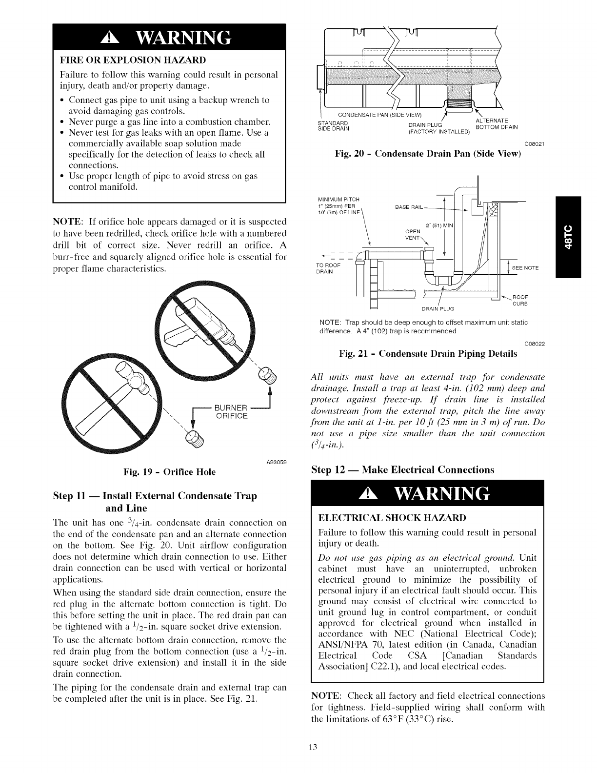
FIRE OR EXPLOSION HAZARD
Failure to follow this warning could result in personal
injury, death and/or property damage.
• Connect gas pipe to unit using a backup wrench to
avoid damaging gas controls.
• Never purge a gas line into a combustion chamber.
• Never test for gas leaks with an open flame. Use a
commercially available soap solution made
specifically for the detection of leaks to check all
connections.
• Use proper length of pipe to avoid stress on gas
control manifold.
NOTE: If orifice hole appears damaged or it is suspected
to have been redrilled, check orifice hole with a numbered
drill bit of correct size. Never redrill an orifice. A
burr-free and squarely aligned orifice hole is essential for
proper flame characteristics.
Fig. 19 - Orifice Hole
A93059
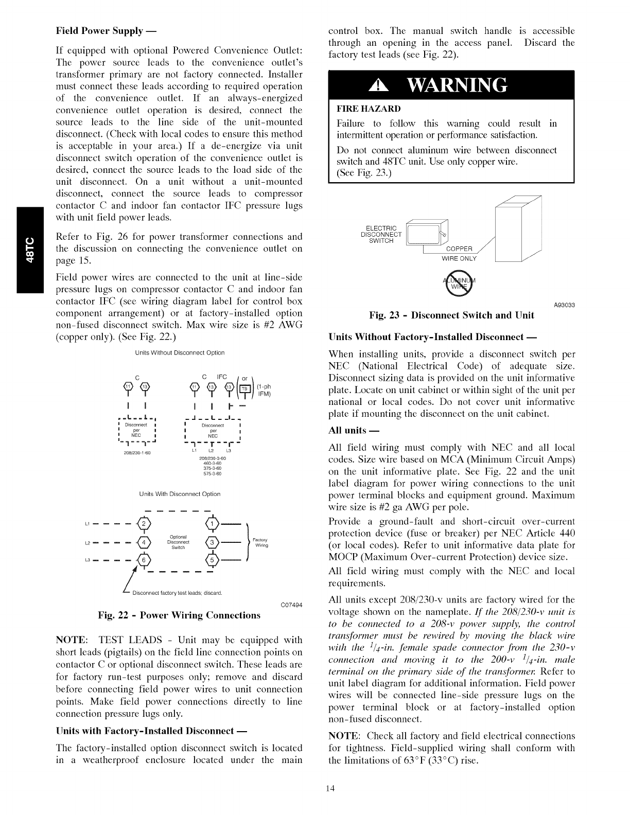
Step 11 -- Install External Condensate Trap
and Line
The unit has one 3/4-in. condensate drain connection on
the end of the condensate pan and an alternate connection
on the bottom. See Fig. 20. Unit airflow configuration
does not determine which drain connection to use. Either
drain connection can be used with vertical or horizontal
applications.
When using the standard side drain connection, ensure the
red plug in the alternate bottom connection is tight. Do
this before setting the unit in place. The red drain pan can
be tightened with a ]/2-in. square socket drive extension.
To use the alternate bottom drain connection, remove the
red drain plug from the bottom connection (use a ]/2-in.
square socket drive extension) and install it in the side
drain connection.
The piping for the condensate drain and external trap can
be completed after the unit is in place. See Fig. 21.
CONDENSATE PAN (SIDE VIEW)
ALTERNATE
STANDARD DRAIN PLUG
SIDE DRAIN BOTTOM DRAIN
(FACTORY-INSTALLED)
Fig. 20 -Condensate Drain Pan (Side View)
C08021
MINIMUM PITCH
TO ROOF
DRAIN
2" (54) MIN
DRAIN PLUG
SEE NOTE
_'---..ROOF
CURB
NOTE: Trap should be deep enough to offset maximum unit static
difference. A 4" (102) trap is recommended
C08022
Fig. 21 - Condensate Drain Piping Details
All units" must have an external trap for condensate
drainage. Install a trap at least 4-in. (102 mm) deep and
protect against freeze-up. If drain line is installed
downstream from the external trap, pitch the line away
from the unit at i-in. per 10 f! (25 mm in 3 in) of run. Do
not use a pipe size smaller than the unit connection
(-%-in.).
Step 12 -- Make Electrical Connections
ELECTRICAL SHOCK HAZARD
Failure to follow this warning could result in personal
injury or death.
Do not use gas piping as an electrical ground. Unit
cabinet must have an uninterrupted, unbroken
electrical ground to minimize the possibility of
personal injury if an electrical fault should occur. This
ground may consist of electrical wire connected to
unit ground lug in control compartment, or conduit
approved for electrical ground when installed in
accordance with NEC (National Electrical Code);
ANSI/NFPA 70, latest edition (in Canada, Canadian
Electrical Code CSA [Canadian Standards
Association] C22.1), and local electrical codes.
NOTE: Check all factory and field electrical connections
for tightness. Field-supplied wiring shall conform with
the limitations of 63°F (33°C) rise.
13
Field Power Supply --
If equipped with optional Powered Convenience Outlet:
The power source leads to the convenience outlet's
transformer primary are not factory connected. Installer
must connect these leads according to required operation
of the convenience outlet. If an always-energized
convenience outlet operation is desired, connect the
source leads to the line side of the unit-mounted
disconnect. (Check with local codes to ensure this method
is acceptable in your area.) If a de-energize via unit
disconnect switch operation of the convenience outlet is
desired, connect the source leads to the load side of the
unit disconnect. On a unit without a unit-mounted
disconnect, connect the source leads to compressor
contactor C and indoor fan contactor IFC pressure lugs
with unit field power leads.
Refer to Fig. 26 for power transformer connections and
the discussion on connecting the convenience outlet on
page 15.
Field power wires are connected to the unit at line-side
pressure lugs on compressor contactor C and indoor fan
contactor IFC (see wiring diagram label for control box
component arrangement) or at factory-installed option
non-fused disconnect switch. Max wire size is #2 AWG
(copper only). (See Fig. 22.)
Units Without Disconnect Option
C
79
J I
.=L=.L= I
I Disconnect a
aper a
INEC a
_-i--7-a
208/230-1-60
9 C?tFC_ (+)
I I I"--
=J=-L-J=_
I Disconnect I
I per I
I NEC I
-7--T--I--
L1 L2 L3
208/230-3-60
460-3-60
375-3-60
575-3-60
(1-ph
IFM)
Units With Disconnect Option
LI
L2 ....
L3 ....
,q> }
,@ o,°2i!i'o,
ZDisconnect factory test leads; discard.
Fig. 22 -Power Wiring Connections
C07494
NOTE: TEST LEADS - Unit may be equipped with
short leads (pigtails) on the field line connection points on
contactor C or optional disconnect switch. These leads are
for factory run-test purposes only; remove and discard
before connecting field power wires to unit connection
points. Make field power connections directly to line
connection pressure lugs only.
Units with Factory-Installed Disconnect --
The factory-installed option disconnect switch is located
in a weatherproof enclosure located under the main
control box. The manual switch handle is accessible
through an opening in the access panel. Discard the
factory test leads (see Fig. 22).
FIRE HAZARD
Failure to follow this warning could result in
intermittent operation or performance satisfaction.
Do not connect aluminum wire between disconnect
switch and 48TC unit. Use only copper wire.
(See Fig. 23.)
ELECTRIC
DISCONNECT
SWITCH WIRE ONLY
@
Fig. 23 - Disconnect Switch and Unit
A93033
Units Without Factory-Installed Disconnect --
When installing units, provide a disconnect switch per
NEC (National Electrical Code) of adequate size.
Disconnect sizing data is provided on the unit informative
plate. Locate on unit cabinet or within sight of the unit per
national or local codes. Do not cover unit informative
plate if mounting the disconnect on the unit cabinet.
All units --
All field wiring must comply with NEC and all local
codes. Size wire based on MCA (Minimum Circuit Amps)
on the unit informative plate. See Fig. 22 and the unit
label diagram for power wiring connections to the unit
power terminal blocks and equipment ground. Maximum
wire size is #2 ga AWG per pole.
Provide a ground-fault and short-circuit over-current
protection device (fuse or breaker) per NEC Article 440
(or local codes). Refer to unit informative data plate for
MOCP (Maximum Over-current Protection) device size.
All field wiring must comply with the NEC and local
requirements.
All units except 208/230-v units are factory wired for the
voltage shown on the nameplate. If the 208/230-v unit is"
to be connected to a 208-v power suppl); the control
transformer must be rewired by moving the black wire
with the 1/4-in. female spade connector from the 230-v
connection and mowng it to the 200-v 1/4-in. male
terminal on the primary side of the transformen Refer to
unit label diagram for additional information. Field power
wires will be connected line-side pressure lugs on the
power terminal block or at factory-installed option
non-fused disconnect.
NOTE: Check all factory and field electrical connections
for tightness. Field-supplied wiring shall conform with
the limitations of 63°F (33°C) rise.
14
Convenience Outlets-
ELECTRICAL OPERATION HAZARD
Failure to follow this warning could result in personal
injury or death.
Units with convenience outlet circuits may use
multiple disconnects. Check convenience outlet for
power status before opening unit for service. Locate
its disconnect switch, if appropriate, and open it.
Tag-out this switch, if necessary.
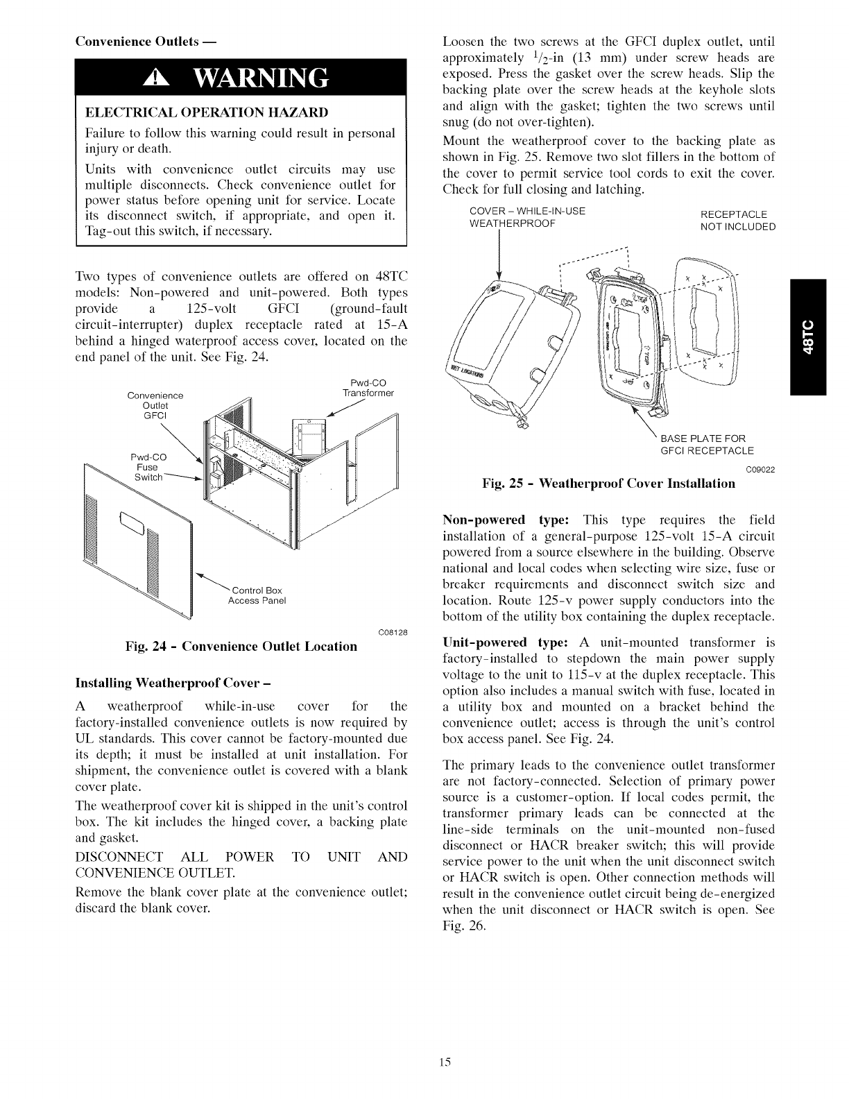
Two types of convenience outlets are offered on 48TC
models: Non-powered and unit-powered. Both types
provide a 125-volt GFCI (ground-fault
circuit-interrupter) duplex receptacle rated at 15-A
behind a hinged waterproof access cover, located on the
end panel of the unit. See Fig. 24.
Pwd-CO
Convenience Transformer
Outlet S
GFCI
Pwd-CO
Fuse
'_ Control Box
Access Panel
C08128
Fig. 24 - Convenience Outlet Location
Installing Weatherproof Cover -
A weatherproof while-in-use cover for the
factory-installed convenience outlets is now required by
UL standards. This cover cannot be factory-mounted due
its depth; it must be installed at unit installation. For
shipment, the convenience outlet is covered with a blank
cover plate.
The weatherproof cover kit is shipped in the unit's control
box. The kit includes the hinged cover, a backing plate
and gasket.
DISCONNECT ALL POWER TO UNIT AND
CONVENIENCE OUTLET.
Remove the blank cover plate at the convenience outlet;
discard the blank cover.
Loosen the two screws at the GFCI duplex outlet, until
approximately 1/2-in (13 mm) under screw heads are
exposed. Press the gasket over the screw heads. Slip the
backing plate over the screw heads at the keyhole slots
and align with the gasket; tighten the two screws until
snug (do not over-tighten).
Mount the weatherproof cover to the backing plate as
shown in Fig. 25. Remove two slot fillers in the bottom of
the cover to permit service tool cords to exit the cover.
Check for full closing and latching.
COVER - WHILE-IN-USE
WEATHERPROOF RECEPTACLE
NOTINCLUDED
BASE PLATE FOR
GFCIRECEPTACLE
C09022
Fig. 25 -Weatherproof Cover Installation
Non-powered type: This type requires the field
installation of a general-purpose 125-volt 15-A circuit
powered from a source elsewhere in the building. Observe
national and local codes when selecting wire size, fuse or
breaker requirements and disconnect switch size and
location. Route 125-v power supply conductors into the
bottom of the utility box containing the duplex receptacle.
Unit-powered type: A unit-mounted transformer is
factory-installed to stepdown the main power supply
voltage to the unit to l15-v at the duplex receptacle. This
option also includes a manual switch with fuse, located in
a utility box and mounted on a bracket behind the
convenience outlet; access is through the unit's control
box access panel. See Fig. 24.
The primary leads to the convenience outlet transformer
are not factory-connected. Selection of primary power
source is a customer-option. If local codes permit, the
transformer primary leads can be connected at the
line-side terminals on the unit-mounted non-fused
disconnect or HACR breaker switch; this will provide
service power to the unit when the unit disconnect switch
or HACR switch is open. Other connection methods will
result in the convenience outlet circuit being de-energized
when the unit disconnect or HACR switch is open. See
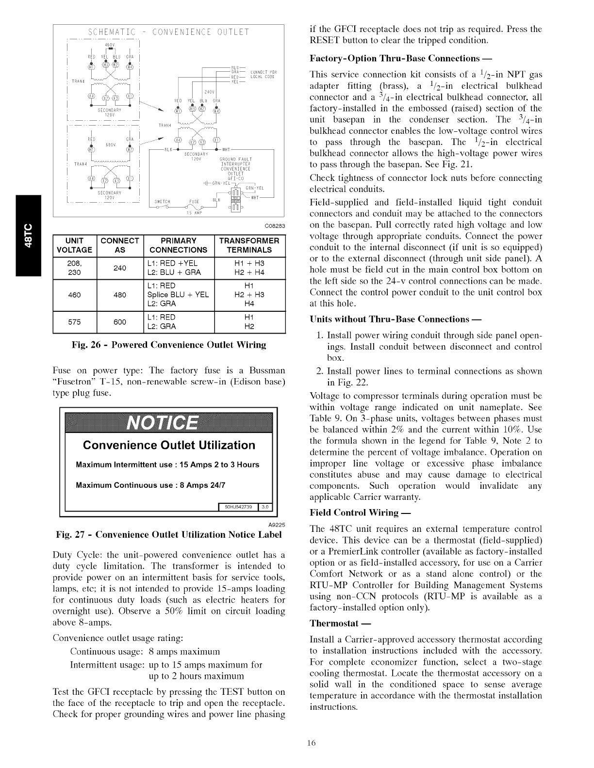
Fig. 26.
15
S?HE aTIfl ..,_1 E IEi/CE C,'TLET
460,/
i_ D ' U Gi!_
....E".M3
T_N4 ........
SECC, ND;R}
120V
BLL
7GR_ C0N_ECT _>E[_
RE{}¸ LOCAL (109E
_EL
I..... _ _ED'ELBLJ G:¢!_I
_, {}i), 'x£ ,}
o, ;o ;q2#U
6FI CO
,IbG_ 'EL
S_/ITCH FSE LK ,,HT
C08283
UNIT CONNECT PRIMARY TRANSFORMER
VOLTAGE AS CONNECTIONS TERMINALS
208, LI: RED+YEL H1 + H3
240
230 L2: BLU + GRA H2 + H4
L1: RED H1
460 480 Splice BLU + YEL H2 + H3
L2: GRA H4
L1: RED H1
575 600 L2: GRA H2
Fig. 26 - Powered Convenience Outlet Wiring
Fuse on power type: The factory fuse is a Bussman
"Fusetron" T-15, non-renewable screw-in (Edison base)
type plug fuse.
Convenience Outlet Utilization
Maximum Intermittent use : 15 Amps 2 to 3 Hours
Maximum Continuous use : 8 Amps 24/7
I 50HJ542739 13.0
A9225
Fig. 27 -Convenience Outlet Utilization Notice Label
Duty Cycle: the unit-powered convenience outlet has a
duty cycle limitation. The transformer is intended to
provide power on an intermittent basis for service tools,
lamps, etc; it is not intended to provide 15-amps loading
for continuous duty loads (such as electric heaters for
overnight use). Observe a 50% limit on circuit loading
above 8-amps.
Convenience outlet usage rating:
Continuous usage: 8 amps maximum
Intermittent usage: up to 15 amps maximum for
up to 2 hours maximum
Test the GFCI receptacle by pressing the TEST button on
the face of the receptacle to trip and open the receptacle.
Check for proper grounding wires and power line phasing
if the GFCI receptacle does not trip as required. Press the
RESET button to clear the tripped condition.
Factory- Option Thru-Base Connections --
This service connection kit consists of a 1/2-in NPT gas
adapter fitting (brass), a 1/2-in electrical bulkhead
connector and a 3/4-in electrical bulkhead connector, all
factory-installed in the embossed (raised) section of the
unit basepan in the condenser section. The 3/4-in
bulkhead connector enables the low-voltage control wires
to pass through the basepan. The 1/2-in electrical
bulkhead connector allows the high-voltage power wires
to pass through the basepan. See Fig. 21.
Check tightness of connector lock nuts before connecting
electrical conduits.
Field-supplied and field-installed liquid tight conduit
connectors and conduit may be attached to the connectors
on the basepan. Pull correctly rated high voltage and low
voltage through appropriate conduits. Connect the power
conduit to the internal disconnect (if unit is so equipped)
or to the external disconnect (through unit side panel). A
hole must be field cut in the main control box bottom on
the left side so the 24-v control connections can be made.
Connect the control power conduit to the unit control box
at this hole.
Units without Thru-Base Connections --
1. Install power wiring conduit through side panel open-
ings. Install conduit between disconnect and control
box.
2. Install power lines to terminal connections as shown
in Fig. 22.
Voltage to compressor terminals during operation must be
within voltage range indicated on unit nameplate. See
Table 9. On 3-phase units, voltages between phases must
be balanced within 2% and the current within 10%. Use
the formula shown in the legend for Table 9, Note 2 to
determine the percent of voltage imbalance. Operation on
improper line voltage or excessive phase imbalance
constitutes abuse and may cause damage to electrical
components. Such operation would invalidate any
applicable Carrier warranty.
Field Control Wiring --
The 48TC unit requires an external temperature control
device. This device can be a thermostat (field-supplied)
or a PremierLink controller (available as factory-installed
option or as field-installed accessory, for use on a Carrier
Comfort Network or as a stand alone control) or the
RTU-MP Controller for Building Management Systems
using non-CCN protocols (RTU-MP is available as a
factory-installed option only).
Thermostat i
Install a Carrier-approved accessory thermostat according
to installation instructions included with the accessory.
For complete economizer function, select a two-stage
cooling thermostat. Locate the thermostat accessory on a
solid wall in the conditioned space to sense average
temperature in accordance with the thermostat installation
instructions.
16
If the thermostat contains a logic circuit requiring 24-v
power, use a thermostat cable or equivalent single leads of
different colors with minimum of seven leads. If the
thermostat does not require a 24-v source (no "C"
connection required), use a thermostat cable or equivalent
with minimum of six leads. Check the thermostat
installation instructions for additional features which
might require additional conductors in the cable.
Using unit-mounted convenience outlets: Units with
unit-mounded convenience outlet circuits will often
require that two disconnects be opened to de-energize all
power to the unit. Treat all units as electrically energized
until the convenience outlet power is also checked and
de-energization is confirmed. Observe National Electrical
Code Article 210, Branch Circuits, for use of convenience
outlets.
For wire runs up to 50 ft. (15 m), use no. 18 AWG
(American Wire Gage) insulated wire [35°C (95°F)
minimum]. For 50 to 75 ft. (15 to 23 m), use no. 16 AWG
insulated wire [35°C (95°F) minimum]. For over 75 ft.
(23 m), use no. 14 AWG insulated wire [35°C (95°F)
minimum]. All wire sizes larger than no. 18 AWG cannot
be directly connected to the thermostat and will require a
junction box and splice at the thermostat.
Typical
Thermostat
Connections
©
@
@
G
(Note 1)
©
®
(Note 2)
Central
Terminal
Board
FwSl
%
%
Fq
T
H
E
R
M
O
S
T
A
T
Note 1 :
Note 2:
mmm
Typical multi4unction marking. Follow manufacturer's configuration
instructions to select Y2.
Y2 to Y2 connection required on single-stage cooling units when
integrated economizer function is desired.
Field Wiring
C08069
Fig. 28 - Low-Voltage Connections
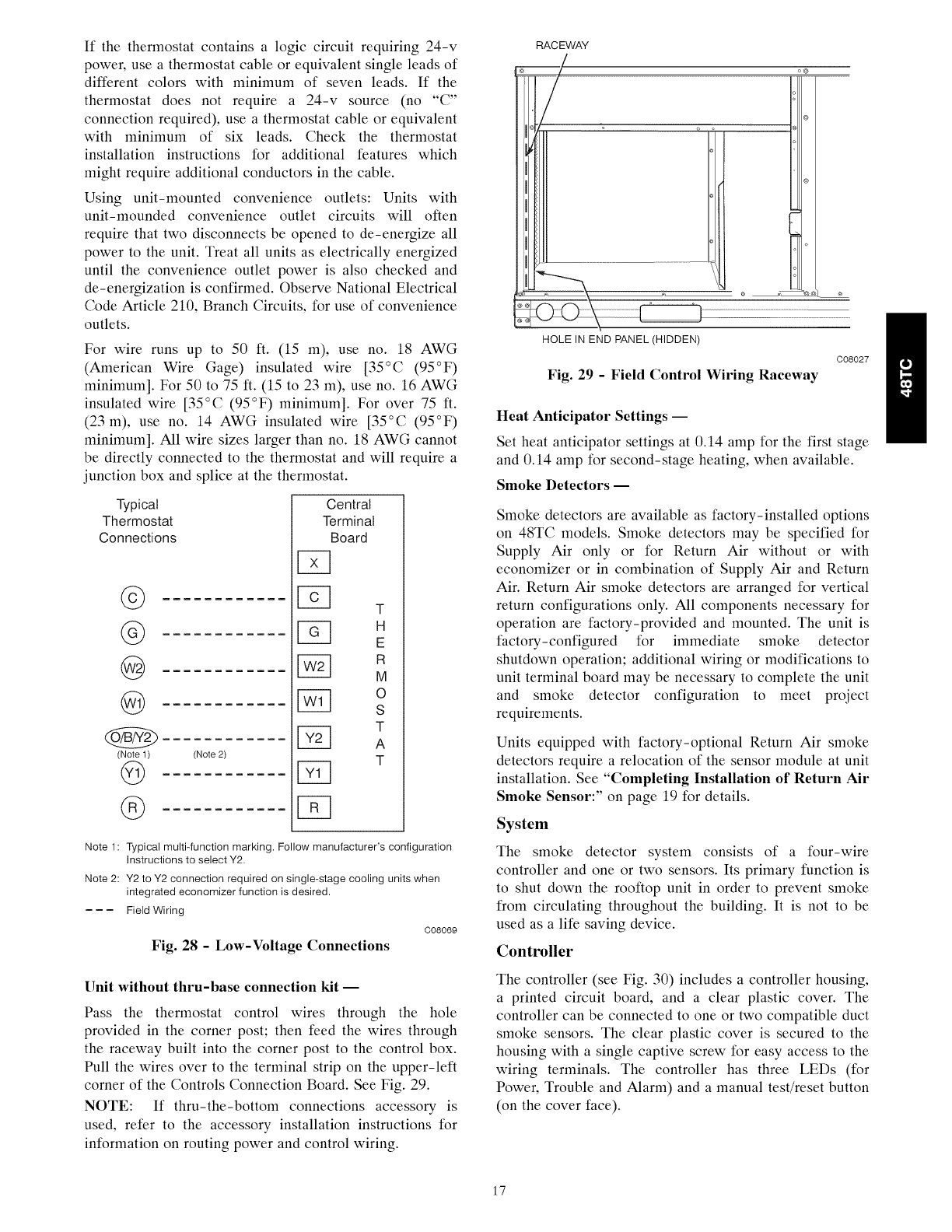
Unit without thru-base connection kit --
Pass the thermostat control wires through the hole
provided in the corner post; then feed the wires through
the raceway built into the corner post to the control box.
Pull the wires over to the terminal strip on the upper-left
corner of the Controls Connection Board. See Fig. 29.
NOTE: If thru-the-bottom connections accessory is
used, refer to the accessory installation instructions for
information on routing power and control wiring.
RACEWAY
HOLE IN END PANEL (HIDDEN)
C08027
Fig. 29 - Field Control Wiring Raceway
Heat Anticipator Settings --
Set heat anticipator settings at 0.14 amp for the first stage
and 0.14 amp for second-stage heating, when available.
Smoke Detectors --
Smoke detectors are available as factory-installed options
on 48TC models. Smoke detectors may be specified for
Supply Air only or for Return Air without or with
economizer or in combination of Supply Air and Return
Air. Return Air smoke detectors are arranged for vertical
return configurations only. All components necessary for
operation are factory-provided and mounted. The unit is
factory-configured for immediate smoke detector
shutdown operation; additional wiring or modifications to
unit terminal board may be necessary to complete the unit
and smoke detector configuration to meet project
requirements.
Units equipped with factory-optional Return Air smoke
detectors require a relocation of the sensor module at unit
installation. See "Completing Installation of Return Air
Smoke Sensor:" on page 19 for details.
System
The smoke detector system consists of a four-wire
controller and one or two sensors. Its primary function is
to shut down the rooftop unit in order to prevent smoke
from circulating throughout the building. It is not to be
used as a life saving device.
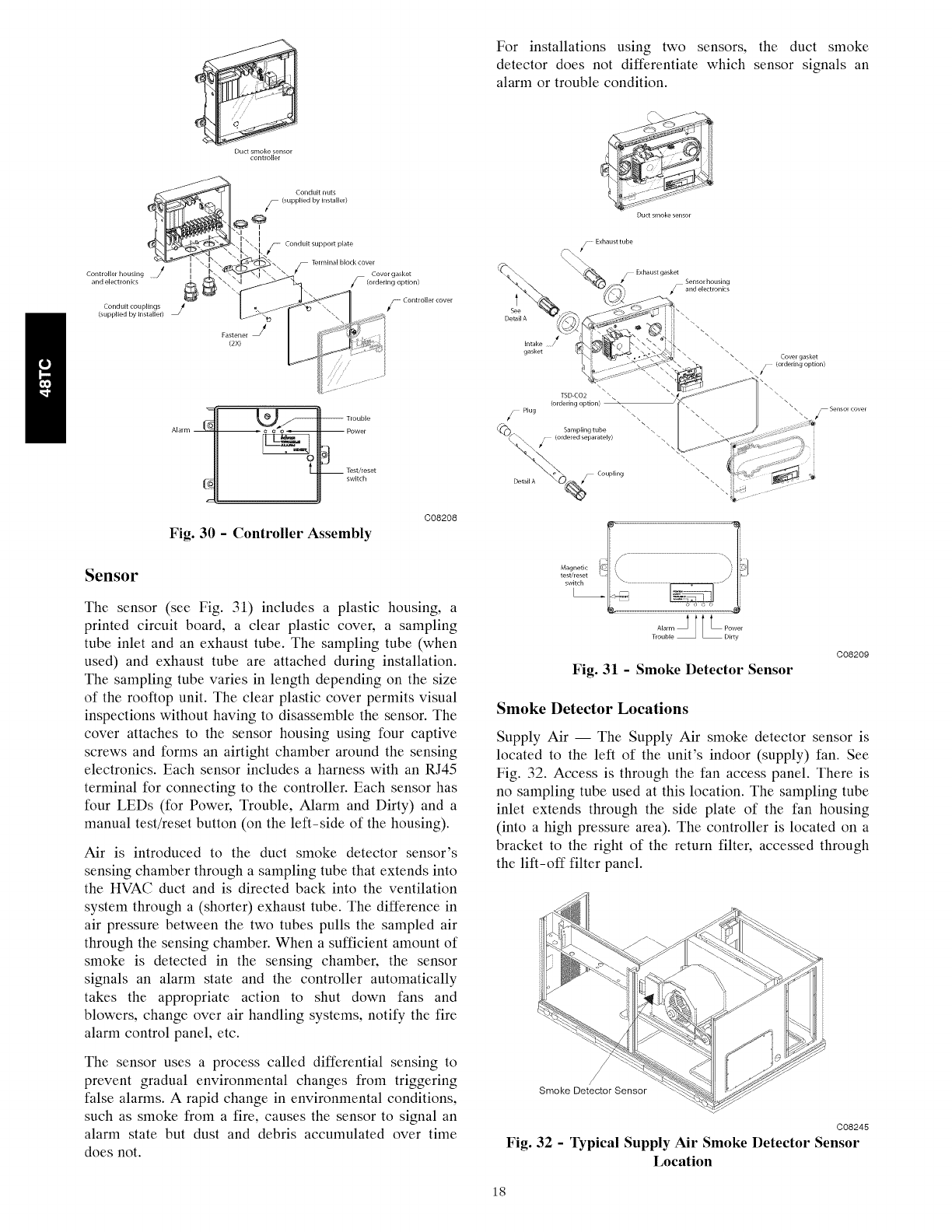
Controller
The controller (see Fig. 30) includes a controller housing,
a printed circuit board, and a clear plastic cover. The
controller can be connected to one or two compatible duct
smoke sensors. The clear plastic cover is secured to the
housing with a single captive screw for easy access to the
wiring terminals. The controller has three LEDs (for
Power, Trouble and Alarm) and a manual test/reset button
(on the cover face).
17
Duct smoke sensor
controller
Controller housing
and electronics
Conduit couplings J
(supplied by installer)
Fastener J
(2x)
Conduit nuts
_ (supplied by installer)
Conduitsupport plate
;_Terminalblockcover Covergasket
F(ordefing option)
_ Controller cover
Trouble
Fig. 30 - Controller Assembly
C08208
Sensor
The sensor (see Fig. 31) includes a plastic housing, a
printed circuit board, a clear plastic cover, a sampling
tube inlet and an exhaust tube. The sampling tube (when
used) and exhaust tube are attached during installation.
The sampling tube varies in length depending on the size
of the rooftop unit. The clear plastic cover permits visual
inspections without having to disassemble the sensor. The
cover attaches to the sensor housing using four captive
screws and forms an airtight chamber around the sensing
electronics. Each sensor includes a harness with an RJ45
terminal for connecting to the controller. Each sensor has
four LEDs (for Power, Trouble, Alarm and Dirty) and a
manual test/reset button (on the left-side of the housing).
Air is introduced to the duct smoke detector sensor's
sensing chamber through a sampling tube that extends into
the HVAC duct and is directed back into the ventilation
system through a (shorter) exhaust tube. The difference in
air pressure between the two tubes pulls the sampled air
through the sensing chamber. When a sufficient amount of
smoke is detected in the sensing chamber, the sensor
signals an alarm state and the controller automatically
takes the appropriate action to shut down fans and
blowers, change over air handling systems, notify the fire
alarm control panel, etc.
The sensor uses a process called differential sensing to
prevent gradual environmental changes from triggering
false alarms. A rapid change in environmental conditions,
such as smoke from a fire, causes the sensor to signal an
alarm state but dust and debris accumulated over time
does not.
For installations using two sensors, the duct smoke
detector does not differentiate which sensor signals an
alarm or trouble condition.
/Exhausttube
t
See
Detail A
Intake /
j Exhaustgasket Sensorhousing
F and electronics
\\\\\\\
gasket \\
\ \ \ \ \ Cover gasket
\\ /(ordering option)
\ \\\ \\\\\
// Plug \_\\ \\ ff Sensor cover
Magnetic I_l_ .....
.......JjL ......
rou e ir
T bl D ty
Fig. 31 -Smoke Detector Sensor
C08209
Smoke Detector Locations
Supply Air -- The Supply Air smoke detector sensor is
located to the left of the unit's indoor (supply) fan. See
Fig. 32. Access is through the fan access panel. There is
no sampling tube used at this location. The sampling tube
inlet extends through the side plate of the fan housing
(into a high pressure area). The controller is located on a
bracket to the right of the return filter, accessed through
the lift-off filter panel.
,/
Smoke Detector Sensor
C08245
Fig. 32 - Typical Supply Air Smoke Detector Sensor
Location
18
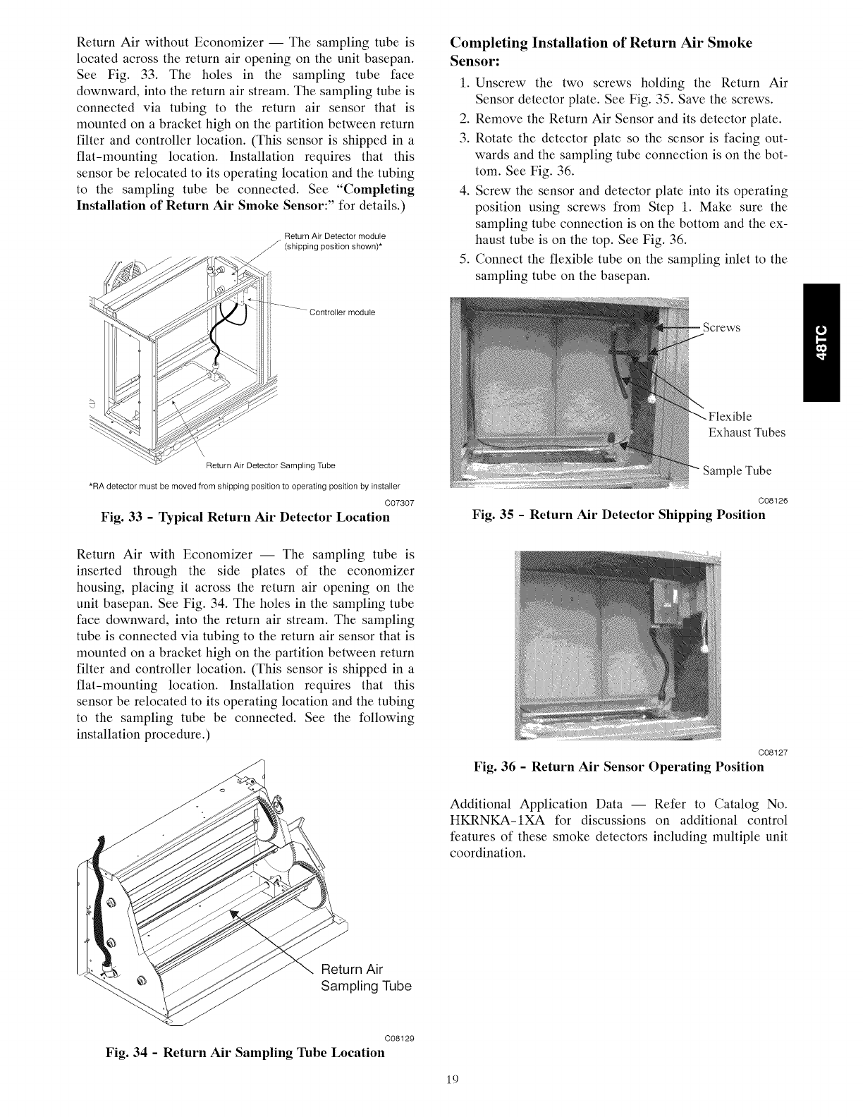
Return Air without Economizer -- The sampling tube is
located across the return air opening on the unit basepan.
See Fig. 33. The holes in the sampling tube face
downward, into the return air stream. The sampling tube is
connected via tubing to the return air sensor that is
mounted on a bracket high on the partition between return
filter and controller location. (This sensor is shipped in a
flat-mounting location. Installation requires that this
sensor be relocated to its operating location and the tubing
to the sampling tube be connected. See "Completing
Installation of Return Air Smoke Sensor:" for details.)
Return Air Detector module
_ (shipping position shown)*
Return Air Detector Sampling Tube
*RA detector must be moved from shipping position to operating position by installer
C07307
Fig. 33 - Typical Return Air Detector Location
Return Air with Economizer -- The sampling tube is
inserted through the side plates of the economizer
housing, placing it across the return air opening on the
unit basepan. See Fig. 34. The holes in the sampling tube
face downward, into the return air stream. The sampling
tube is connected via tubing to the return air sensor that is
mounted on a bracket high on the partition between return
filter and controller location. (This sensor is shipped in a
flat-mounting location. Installation requires that this
sensor be relocated to its operating location and the tubing
to the sampling tube be connected. See the following
installation procedure.)
Completing Installation of Return Air Smoke
Sensor:
1. Unscrew the two screws holding the Return Air
Sensor detector plate. See Fig. 35. Save the screws.
2. Remove the Return Air Sensor and its detector plate.
3. Rotate the detector plate so the sensor is facing out-
wards and the sampling tube connection is on the bot-
tom. See Fig. 36.
4. Screw the sensor and detector plate into its operating
position using screws from Step 1. Make sure the
sampling tube connection is on the bottom and the ex-
haust tube is on the top. See Fig. 36.
5. Connect the flexible tube on the sampling inlet to the
sampling tube on the basepan.
Exhaust Tubes
Sample Tube
C08126
Fig. 35 -Return Air Detector Shipping Position
C08127
Fig. 36 -Return Air Sensor Operating Position
Additional Application Data -- Refer to Catalog No.
HKRNKA-1XA for discussions on additional control
features of these smoke detectors including multiple unit
coordination.
_/< Return Air
Sampling Tube
C08129
Fig. 34 - Return Air Sampling Tube Location
19
PremierLink (Factory-Option) --
HVAC SENSOR INPUTS
SPACE TEMP _._
SET POINT ._
SUPPLY AIR TEMP -__
OUTDOOR TEMP _--_
INDOOR AIR QUALITY -_
OUTDOOR AIR QUALITY
DUAL MODE SENSOR!STAT
COMP SAFETY (Y1) 7
FIRE SHUTDOWN (Y2) /_
SUPPLY FAN STATUS (Wl)
NOT USED (W2) _'_
..I
ENTHALPY STATUS (ENTH)
o c
_ 8_mu{Z_°AJ .............................
TSTATC_ ]
8tU s_r Gm ,_ _¢ I
_N Am ! C t& t_m Paff Nt_be_ 330SPREMLK
2;_1oi PremcerL_nk _,.... --
.m__ [
lII=, .....-..............°tt
\ k_Jl,_0'l| 'I 'I &° '1 'i '1
/f/t",..
CCN/LEN NAVIGATOR 4-20MA INDOOR COMPR HEAT EXHAUST
PORT PORT ECONOMIZER FAN MOTOR 1 & 2 LOW/HIGH RVS VALVE
OUTPUTS
Fig. 37 - PremierLink Controller
C08199
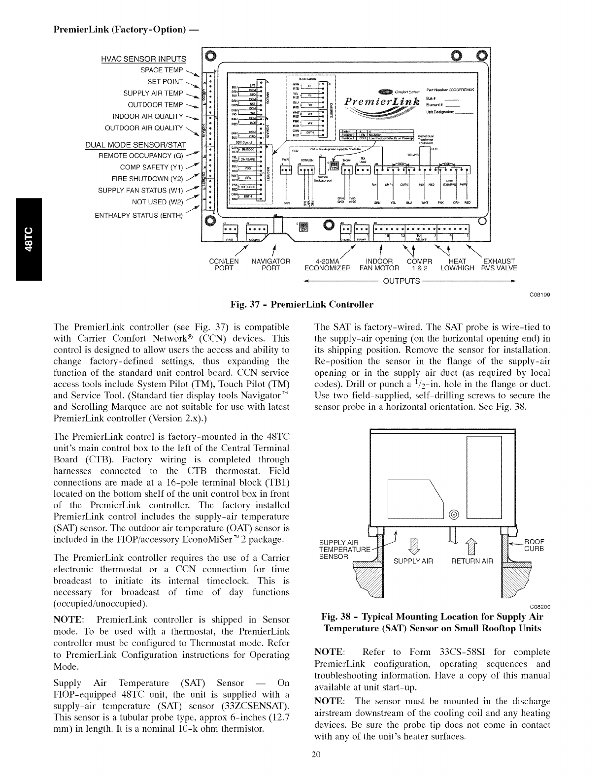
The PremierLink controller (see Fig. 37) is compatible
with Carrier Comfort Network ® (CCN) devices. This
control is designed to allow users the access and ability to
change factory-defined settings, thus expanding the
function of the standard unit control board. CCN service
access tools include System Pilot (TM), Touch Pilot (TM)
and Service Tool. (Standard tier display tools Navigator TM
and Scrolling Marquee are not suitable for use with latest
PremierLink controller (Version 2.x).)
The PremierLink control is factory-mounted in the 48TC
unit's main control box to the left of the Central Terminal
Board (CTB). Factory wiring is completed through
harnesses connected to the CTB thermostat. Field
connections are made at a 16-pole terminal block (TB1)
located on the bottom shelf of the unit control box in front
of the PremierLink controller. The factory-installed
PremierLink control includes the supply-air temperature
(SAT) sensor. The outdoor air temperature (OAT) sensor is
included in the FIOP/accessory EconoMi$er TM 2 package.
The PremierLink controller requires the use of a Carrier
electronic thermostat or a CCN connection for time
broadcast to initiate its internal timeclock. This is
necessary for broadcast of time of day functions
(occupied/unoccupied).
NOTE: PremierLink controller is shipped in Sensor
mode. To be used with a thermostat, the PremierLink
controller must be configured to Thermostat mode. Refer
to PremierLink Configuration instructions for Operating
Mode.
Supply Air Temperature (SAT) Sensor -- On
FlOP-equipped 48TC unit, the unit is supplied with a
supply-air temperature (SAT) sensor (33ZCSENSAT).
This sensor is a tubular probe type, approx 6-inches (12.7
mm) in length. It is a nominal 10-k ohm thermistor.
The SAT is factory-wired. The SAT probe is wire-tied to
the supply-air opening (on the horizontal opening end) in
its shipping position. Remove the sensor for installation.
Re-position the sensor in the flange of the supply-air
opening or in the supply air duct (as required by local
codes). Drill or punch a 1/2-in. hole in the flange or duct.
Use two field-supplied, self-drilling screws to secure the
sensor probe in a horizontal orientation. See Fig. 38.
\
SENSOR _ SUPPLYAIR
m
RETURN AIR
C08200
Fig. 38 - Typical Mounting Location for Supply Air
Temperature (SAT) Sensor on Small Rooftop Units
NOTE: Refer to Form 33CS-58SI for complete
PremierLink configuration, operating sequences and
troubleshooting information. Have a copy of this manual
available at unit start-up.
NOTE: The sensor must be mounted in the discharge
airstream downstream of the cooling coil and any heating
devices. Be sure the probe tip does not come in contact
with any of the unit's heater surfaces.
2O
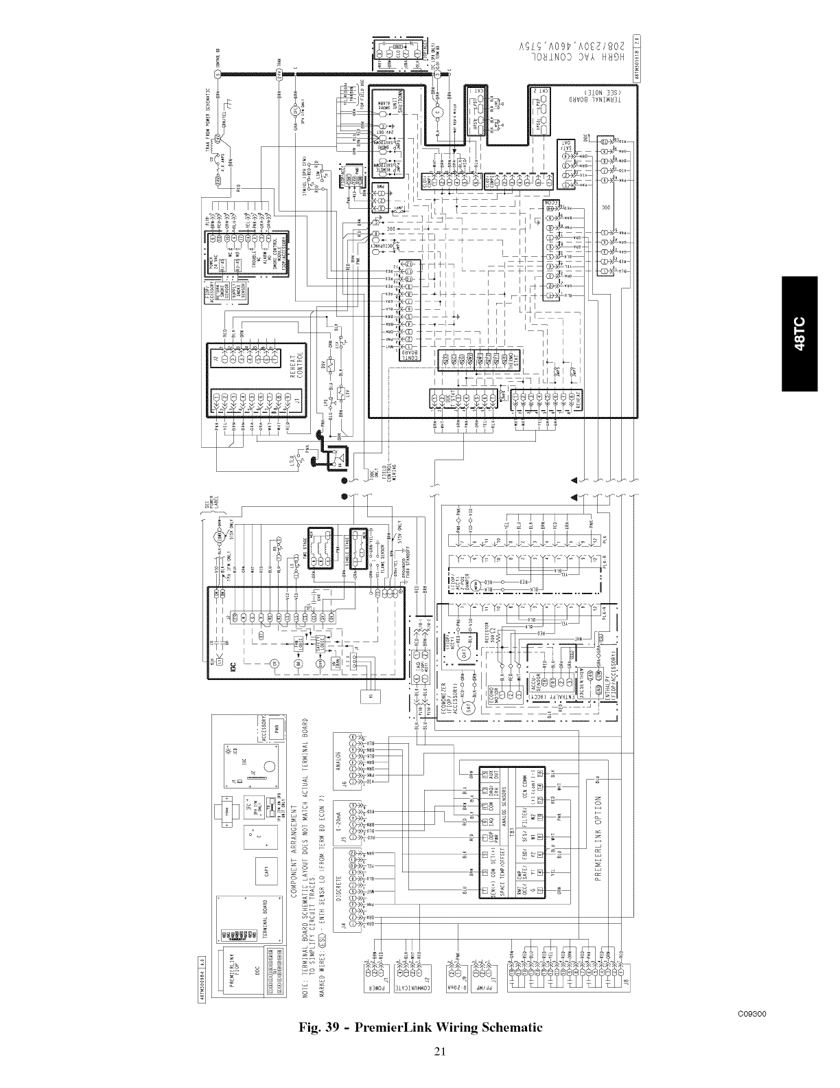
Fig. 39 - PremierLink Wiring Schematic
21
C09300
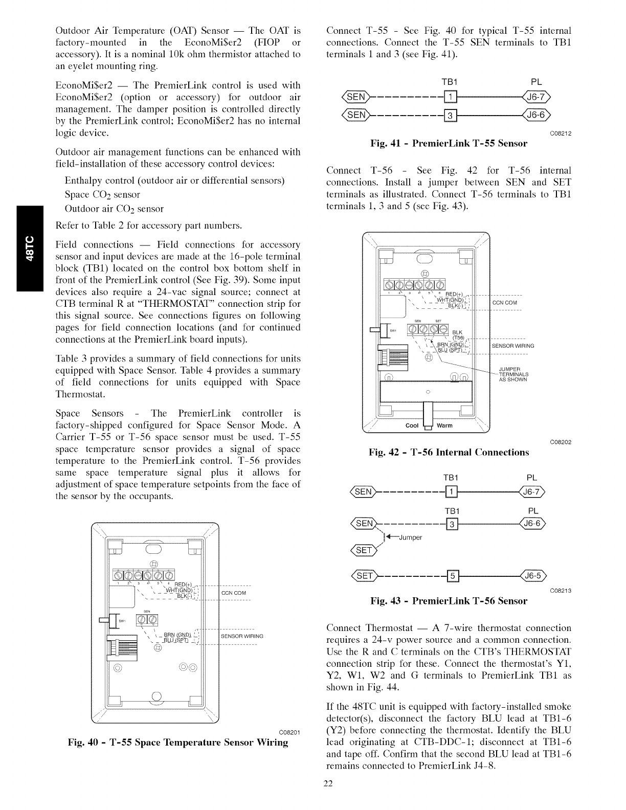
Outdoor Air Temperature (OAT) Sensor I The OAT is
factory-mounted in the EconoMi$er2 (FIOP or
accessory). It is a nominal 10k ohm thermistor attached to
an eyelet mounting ring.
EconoMi$er2 I The PremierLink control is used with
EconoMiSer2 (option or accessory) for outdoor air
management. The damper position is controlled directly
by the PremierLink control; EconoMi$er2 has no internal
logic device.
Outdoor air management functions can be enhanced with
field-installation of these accessory control devices:
Enthalpy control (outdoor air or differential sensors)
Space CO: sensor
Outdoor air CO: sensor
Refer to Table 2 for accessory part numbers.
Field connections I Field connections for accessory
sensor and input devices are made at the 16-pole terminal
block (TB1) located on the control box bottom shelf in
front of the PremierLink control (See Fig. 39). Some input
devices also require a 24-vac signal source; connect at
CTB terminal R at "THERMOSTAT" connection strip for
this signal source. See connections figures on following
pages for field connection locations (and for continued
connections at the PremierLink board inputs).
Table 3 provides a summary of field connections for units
equipped with Space Sensor. Table 4 provides a summary
of field connections for units equipped with Space
Thermostat.
Space Sensors -The PremierLink controller is
factory-shipped configured for Space Sensor Mode. A
Carrier T-55 or T-56 space sensor must be used. T-55
space temperature sensor provides a signal of space
temperature to the PremierLink control. T-56 provides
same space temperature signal plus it allows for
adjustment of space temperature setpoints from the face of
the sensor by the occupants.
s_
©
_ .\ 5,,_ 0Ep(+)j.
_, _ _W_HL(Q_N_)L',
\ BL@)t]
Wl
\ / BRN (GND& [ ',
@
4:b,
©
CCN COM
SENSOR WIRING
C08201
Fig. 40 -T-55 Space Temperature Sensor Wiring
Connect T-55 -See Fig. 40 for typical T-55 internal
connections. Connect the T-55 SEN terminals to TB1
terminals 1 and 3 (see Fig. 41).
TB1 PL
C08212
Fig. 41 - PremierLink T-55 Sensor
Connect T-56 -See Fig. 42 for T-56 internal
connections. Install a jumper between SEN and SET
terminals as illustrated. Connect T-56 terminals to TB1
terminals 1, 3 and 5 (see Fig. 43).
©
©
CCN COM
SENSOR WIRING
JUMPER
TERM INALS
AS SHOWN
Fig. 42 -T-56 Internal Connections
C08202
<NA>
!_l'---Jumper
TB1
D
TB1
%
PL
PL
D
C08213
Fig. 43 -PremierLink T-56 Sensor
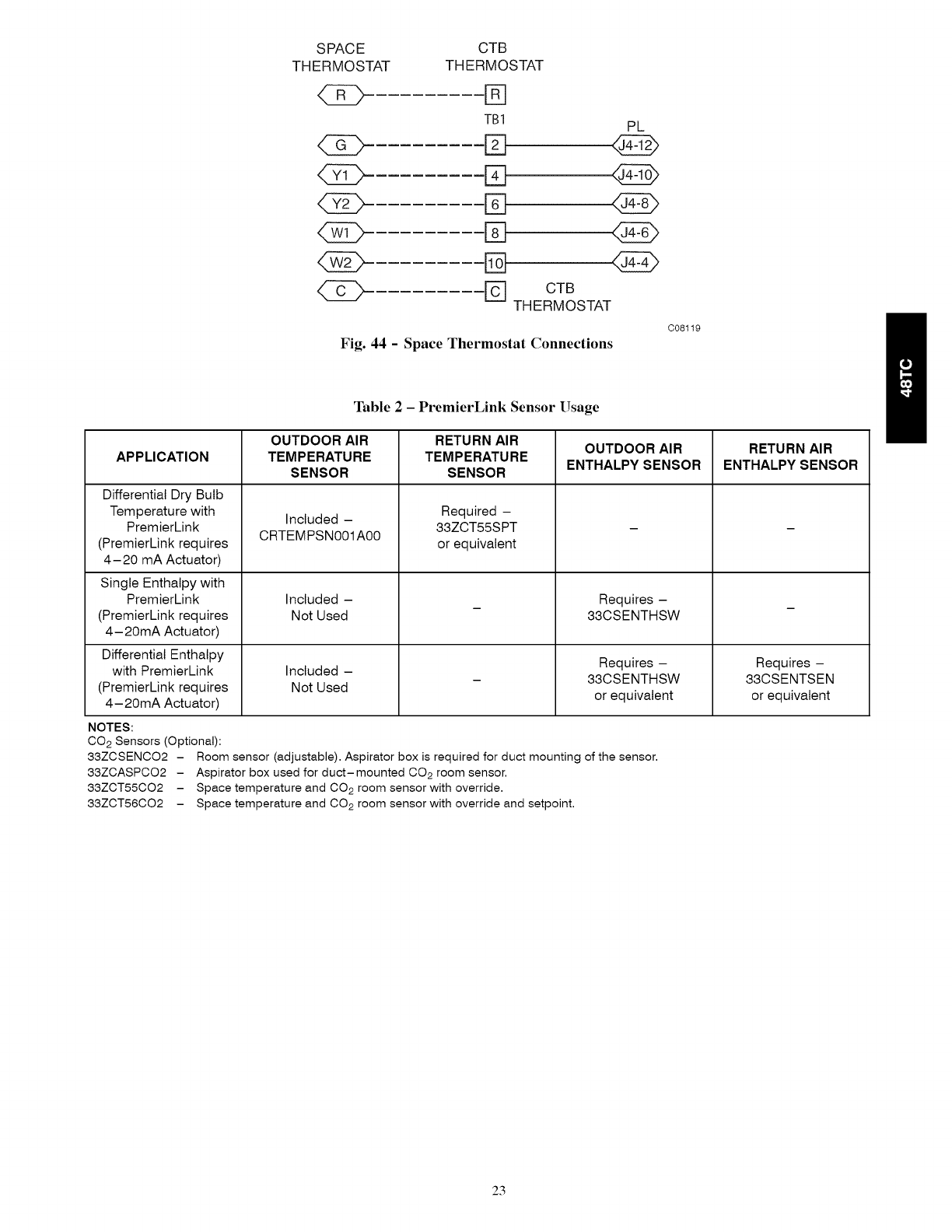
Connect Thermostat I A 7-wire thermostat connection
requires a 24-v power source and a common connection.
Use the R and C terminals on the CTB's THERMOSTAT
connection strip for these. Connect the thermostat's Y1,
Y2, W1, W2 and Gterminals to PremierLink TB1 as
shown in Fig. 44.
If the 48TC unit is equipped with factory-installed smoke
detector(s), disconnect the factory BLU lead at TB1-6
(Y2) before connecting the thermostat. Identify the BLU
lead originating at CTB-DDC-1; disconnect at TB1-6
and tape off. Confirm that the second BLU lead at TB1-6
remains connected to PremierLink J4-8.
22
SPACE CTB
THERMOSTAT THERMOSTAT
D
TB1 PL
42D E]
(Z) %
CTB
THERMOSTAT
Fig. 44 - Space Thermostat Connections
C08119
Table 2-PremierLink Sensor Usage
OUTDOOR AIR RETURN AIR OUTDOOR AIR RETURN AIR
APPLICATION TEMPERATURE TEMPERATURE ENTHALPY SENSOR ENTHALPY SENSOR
SENSOR SENSOR
Differential Dry Bulb
Temperature with
PremierLink
(PremierLink requires
4- 20 mA Actuator)
Single Enthalpy with
PremierLink
(PremierLink requires
4- 20mA Actuator)
Differential Enthalpy
with PremierLink
(PremierLink requires
4- 20mA Actuator)
Included -
CRTEMPSNOO1AO0
Included -
Not Used
Included -
Not Used
Required -
33ZCT55SPT
or equivalent
Requires -
33CSENTHSW
Requires -
33CSENTHSW
or equivalent
NOTES:
CO 2 Sensors (Optional):
33ZCSENC02 - Room sensor (adjustable). Aspirator box is required for duct mounting of the sensor.
33ZCASPC02 - Aspirator box used for duct-mounted CO 2 room sensor.
33ZCT55C02 - Space temperature and CO2 room sensor with override.
33ZCT56C02 - Space temperature and CO2 room sensor with override and setpoint.
Requires -
33CSENTSEN
or equivalent
23
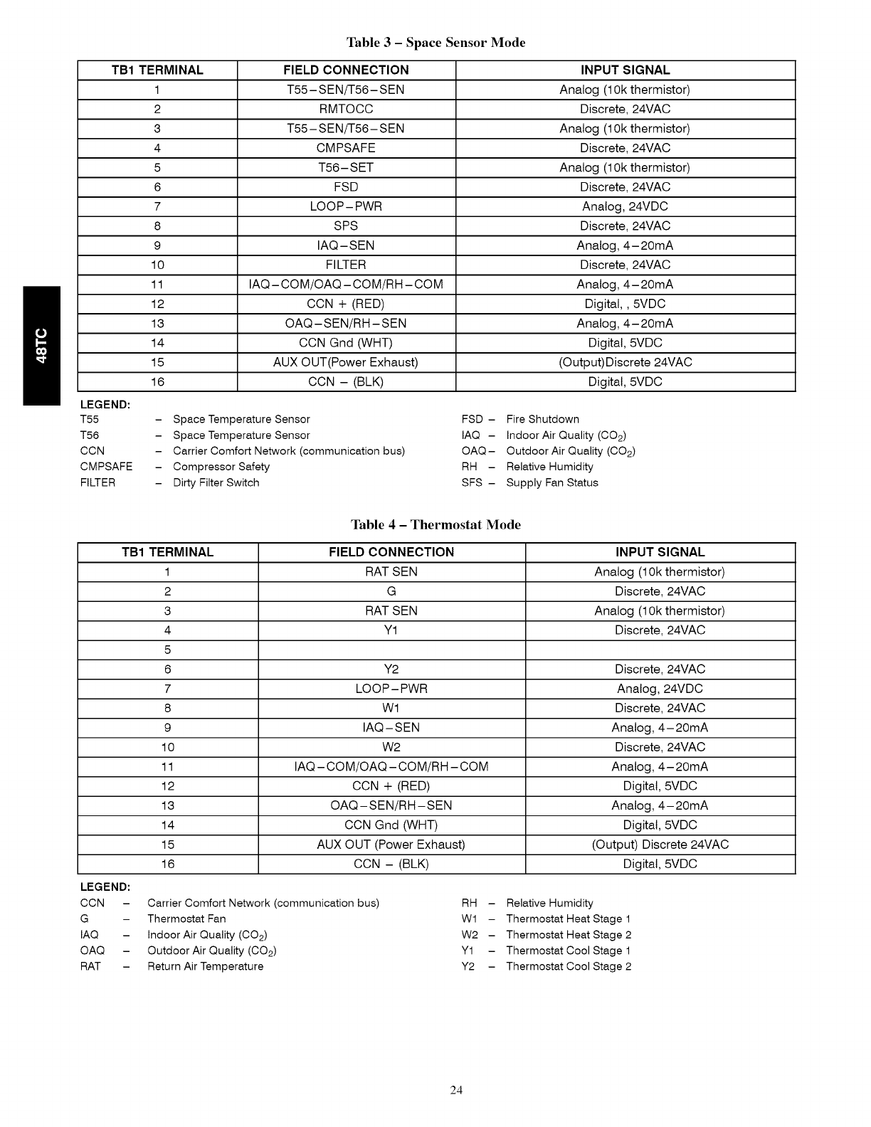
Table 3 - Space Sensor Mode
TB1 TERMINAL
1
2
3
4
5
6
7
8
9
10
11
12
13
14
15
16
LEGEND:
T55
T56
CCN
CMPSAFE -
FILTER
FIELD CONNECTION INPUT SIGNAL
T55- SEN/T56- SEN Analog (1Okthermistor)
RMTOCC Discrete, 24VAC
T55- SEN/T56- SEN Analog (1Okthermistor)
CMPSAFE Discrete, 24VAC
T56- SET Analog (1Okthermistor)
FSD Discrete, 24VAC
LOOP- PWR Analog, 24VDC
SPS Discrete, 24VAC
IAQ-SEN Analog, 4-20mA
FILTER Discrete, 24VAC
IAQ- COM/OAQ- COM/RH- COM Analog, 4-20mA
CCN + (RED) Digital,, 5VDC
OAQ-SEN/RH-SEN Analog, 4-20mA
CCN Gnd (WriT) Digital, 5VDC
AUX OUT(Power Exhaust) (Output)Discrete 24VAC
CCN - (BLK) Digital, 5VDC
Space Temperature Sensor
Space Temperature Sensor
Carrier Comfort Network (communication bus)
Compressor Safety
Dirty Filter Switch
FSD - Fire Shutdown
IAQ - Indoor Air Quality (C02)
OAQ- Outdoor Air Quality (C02)
RH - Relative Humidity
SFS - Supply Fan Status
Table 4 - Thermostat Mode
TB1 TERMINAL FIELD CONNECTION INPUT SIGNAL
1 RAT SEN Analog (10k thermistor)
2 G Discrete, 24VAC
3 RAT SEN Analog (1Ok thermistor)
4 Y1 Discrete, 24VAC
5
6 Y2 Discrete, 24VAC
7 LOOP- PWR Analog, 24VDC
8 Wl Discrete, 24VAC
9 IAQ-SEN Analog, 4-20mA
10 W2 Discrete, 24VAC
11 IAQ- COM/OAQ- COM/RH-COM Analog, 4- 20mA
12 CCN + (RED) Digital, 5VDC
13 OAQ - SEN/RH - SEN Analog, 4- 20mA
14 CCN Gnd (WriT) Digital, 5VDC
15 AUX OUT (Power Exhaust) (Output) Discrete 24VAC
16 CCN - (BLK) Digital, 5VDC
LEGEND:
CCN -
G
IAQ -
OAQ -
RAT -
Carrier Comfort Network (communication bus)
Thermostat Fan
Indoor Air Quality (C02)
Outdoor Air Quality (C02)
Return Air Temperature
RH - Relative Humidity
Wl - Thermostat Heat Stage 1
W2 - Thermostat Heat Stage 2
Y1 - Thermostat Cool Stage 1
Y2 - Thermostat Cool Stage 2
24
If the 48TC unit has an economizer system and
free-cooling operation is required, a sensor representing
Return Air Temperature must also be connected
(field-supplied and installed). This sensor may be a T-55
Space Sensor (see Fig. 40) installed in the space or in the
return duct, or it may be sensor PNO 33ZCSENSAT,
installed in the return duct. Connect this sensor to TBI-1
and TB1-3 per Fig. 41.
Configure the unit for Thermostat Mode I Connect to the
CCN bus using a CCN service tool and navigate to
PremierLink Configuration screen for Operating Mode.
Default setting is Sensor Mode (value 1). Change the
value to 0 to reconfigure the controller for Thermostat
Mode.
When the PremierLink is configured for Thermostat
Mode, these functions are not available: Fire Shutdown
(FSD), Remote Occupied (RMTOCC), Compressor Safety
(CMPSAFE), Supply Fan Status (SFS), and Filter Pressure
Switch (FILTER).
Economizer controls i
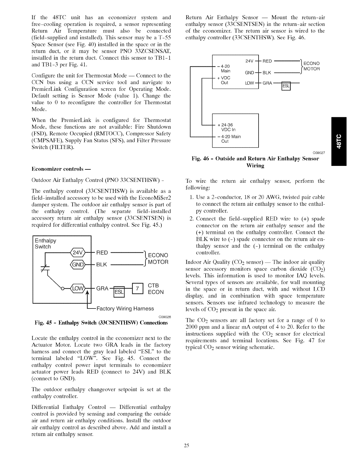
Return Air Enthalpy Sensor I Mount the return-air
enthalpy sensor (33CSENTSEN) in the return-air section
of the economizer. The return air sensor is wired to the
enthalpy controller (33CSENTHSW). See Fig. 46.
-4-20
Main
+ VDC
Out
+ 24-36
VDC In
-4-20 Main
Out
|
24V ? RED --'_ECONO
GND T| BLK .JMOTOR
LOW 1- GRA _
C09027
Fig. 46 - Outside and Return Air Enthalpy Sensor
Wiring
Outdoor Air Enthalpy Control (PNO 33CSENTHSW) -
The enthalpy control (33CSENTHSW) is available as a
field-installed accessory to be used with the EconoMi$er2
damper system. The outdoor air enthalpy sensor is part of
the enthalpy control. (The separate field-installed
accessory return air enthalpy sensor (33CSENTSEN) is
required for differential enthalpy control. See Fig. 45.)
Enthalpy
Switch
=RED '_ECONO
BLK ,JMOTOR
GRA_ E__ CTB
ECON
m Factory Wiring Harness
C09026
Fig. 45 -Enthalpy Switch (33CSENTHSW) Connections
Locate the enthalpy control in the economizer next to the
Actuator Motor. Locate two GRA leads in the factory
harness and connect the gray lead labeled "ESL" to the
terminal labeled "LOW". See Fig. 45. Connect the
enthalpy control power input terminals to economizer
actuator power leads RED (connect to 24V) and BLK
(connect to GND).
The outdoor enthalpy changeover setpoint is set at the
enthalpy controller.
To wire the return air enthalpy sensor, perform the
following:
1. Use a 2-conductor, 18 or 20 AWG, twisted pair cable
to connect the return air enthalpy sensor to the enthal-
py controller.
2. Connect the field-supplied RED wire to (+) spade
connector on the return air enthalpy sensor and the
(+) terminal on the enthalpy controller. Connect the
BLK wire to (-) spade connector on the return air en-
thalpy sensor and the (-) terminal on the enthalpy
controller.
Indoor Air Quality (CO2 sensor) I The indoor air quality
sensor accessory monitors space carbon dioxide (CO2)
levels. This information is used to monitor IAQ levels.
Several types of sensors are available, for wall mounting
in the space or in return duct, with and without LCD
display, and in combination with space temperature
sensors. Sensors use infrared technology to measure the
levels of CO2 present in the space air.
The CO2 sensors are all factory set for a range of 0 to
2000 ppm and a linear mA output of 4 to 20. Refer to the
instructions supplied with the CO2 sensor for electrical
requirements and terminal locations. See Fig. 47 for
typical CO2 sensor wiring schematic.
Differential Enthalpy Control I Differential enthalpy
control is provided by sensing and comparing the outside
air and return air enthalpy conditions. Install the outdoor
air enthalpy control as described above. Add and install a
return air enthalpy sensor.
25
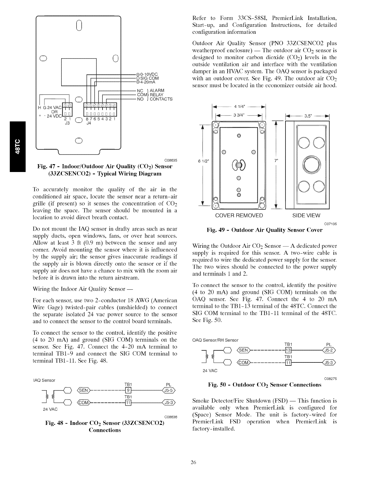
0
H
2 1 O 87654321
J3 J4
Q0q0VDC
® SIG COM
® 4-20mA
NC '} ALARM
COM_, RELAY
NO J CONTACTS
O
C08635
Fig. 47 - Indoor/Outdoor Air Quality (CO2) Sensor
(33ZCSENCO2) - Typical Wiring Diagram
To accurately monitor the quality of the air in the
conditioned air space, locate the sensor near a return-air
grille (if present) so it senses the concentration of CO2
leaving the space. The sensor should be mounted in a
location to avoid direct breath contact.
Do not mount the IAQ sensor in drafty areas such as near
supply ducts, open windows, fans, or over heat sources.
Allow at least 3 ft (0.9 m) between the sensor and any
corner. Avoid mounting the sensor where it is influenced
by the supply air; the sensor gives inaccurate readings if
the supply air is blown directly onto the sensor or if the
supply air does not have a chance to mix with the room air
before it is drawn into the return airstream.
Wiring the Indoor Air Quality Sensor --
For each sensor, use two 2-conductor 18 AWG (American
Wire Gage) twisted-pair cables (unshielded) to connect
the separate isolated 24 vac power source to the sensor
and to connect the sensor to the control board terminals.
To connect the sensor to the control, identify the positive
(4 to 20 mA) and ground (SIG COM) terminals on the
sensor. See Fig. 47. Connect the 4-20 mA terminal to
terminal TB1-9 and connect the SIG COM terminal to
terminal TBI-ll. See Fig. 48.
IAQ Sensor
TB1 PL
TB1
<gg> []
24 VAC
C08636
Fig. 48 - Indoor CO2 Sensor (33ZCSENCO2)
Connections
Refer to Form 33CS-58SI, PremierLink Installation,
Start-up, and Configuration Instructions, for detailed
configuration information
Outdoor Air Quality Sensor (PNO 33ZCSENCO2 plus
weatherproof enclosure) -- The outdoor air CO2 sensor is
designed to monitor carbon dioxide (CO2) levels in the
outside ventilation air and interface with the ventilation
damper in an HVAC system. The OAQ sensor is packaged
with an outdoor cover. See Fig. 49. The outdoor air CO2
sensor must be located in the economizer outside air hood.
61t2"
_1-- 41/4" ......................t_
_4_---- 33/4" --_b,,]
© @
@
@
@
COVER REMOVED
--,--
7u
...... 3.5" ........
OC
O
OO
SIDE VIEW
C07135
Fig. 49 - Outdoor Air Quality Sensor Cover
Wiring the Outdoor Air CO2 Sensor -- A dedicated power
supply is required for this sensor. A two-wire cable is
required to wire the dedicated power supply for the sensor.
The two wires should be connected to the power supply
and terminals 1 and 2.
To connect the sensor to the control, identify the positive
(4 to 20 mA) and ground (SIG COM) terminals on the
OAQ sensor. See Fig. 47. Connect the 4 to 20 mA
terminal to the TB1-13 terminal of the 48TC. Connect the
SIG COM terminal to the TBI-ll terminal of the 48TC.
See Fig. 50.
OAQ Sensor/RH Sensor TB1 PL
TB1
@ Fq
24 VAC
C08275
Fig. 50 - Outdoor CO 2 Sensor Connections
Smoke Detector/Fire Shutdown (FSD) -- This function is
available only when PremierLink is configured for
(Space) Sensor Mode. The unit is factory-wired for
PremierLink FSD operation when PremierLink is
factory-installed.
26
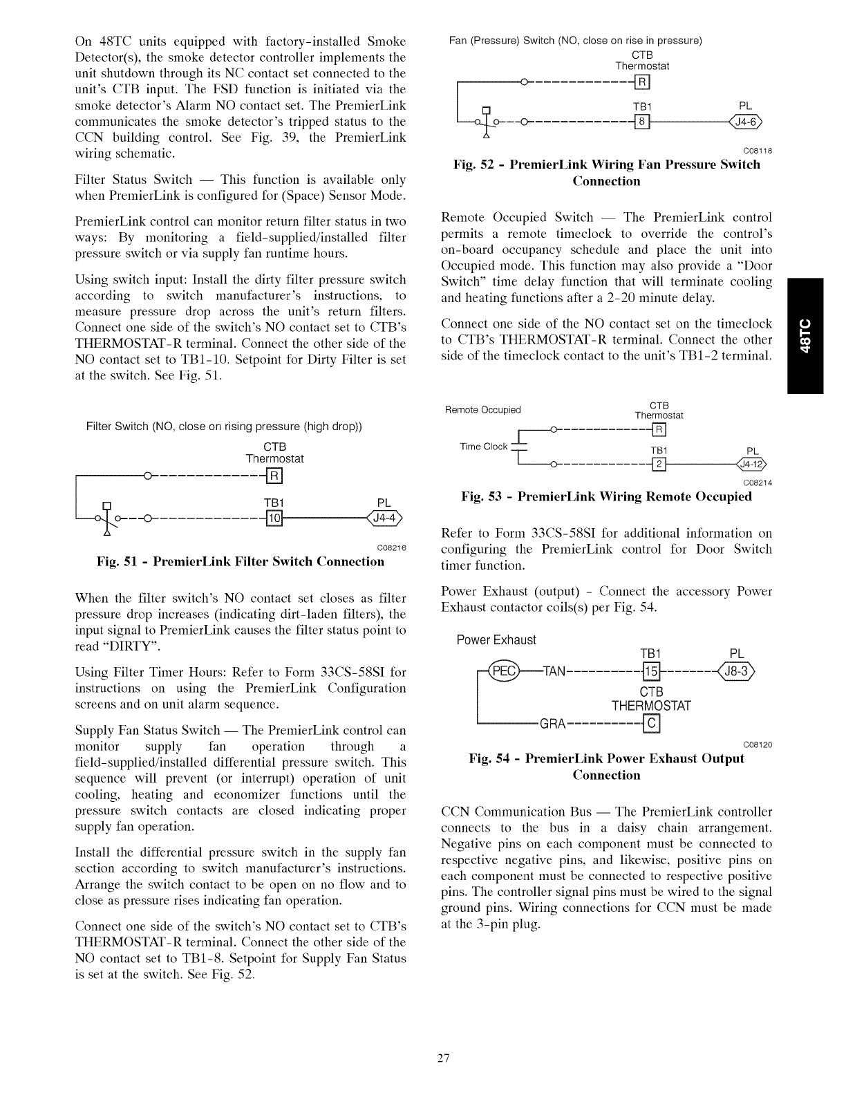
On 48TC units equipped with factory-installed Smoke
Detector(s), the smoke detector controller implements the
unit shutdown through its NC contact set connected to the
unit's CTB input. The FSD function is initiated via the
smoke detector's Alarm NO contact set. The PremierLink
communicates the smoke detector's tripped status to the
CCN building control. See Fig. 39, the PremierLink
wiring schematic.
Filter Status Switch I This function is available only
when PremierLink is configured for (Space) Sensor Mode.
PremierLink control can monitor return filter status in two
ways: By monitoring a field-supplied/installed filter
pressure switch or via supply fan runtime hours.
Using switch input: Install the dirty filter pressure switch
according to switch manufacturer's instructions, to
measure pressure drop across the unit's return filters.
Connect one side of the switch's NO contact set to CTB's
THERMOSTAT-R terminal. Connect the other side of the
NO contact set to TBI-10. Setpoint for Dirty Filter is set
at the switch. See Fig. 51.
Filter Switch (NO, close on rising pressure (high drop))
CTB
Thermostat
TB1 PL
--o D 427
C08216
Fig. 51 - PremierLink Filter Switch Connection
When the filter switch's NO contact set closes as filter
pressure drop increases (indicating dirt-laden filters), the
input signal to PremierLink causes the filter status point to
read "DIRTY".
Using Filter Timer Hours: Refer to Form 33CS-58SI for
instructions on using the PremierLink Configuration
screens and on unit alarm sequence.
Supply Fan Status Switch I The PremierLink control can
monitor supply fan operation through a
field-supplied/installed differential pressure switch. This
sequence will prevent (or interrupt) operation of unit
cooling, heating and economizer functions until the
pressure switch contacts are closed indicating proper
supply fan operation.
Install the differential pressure switch in the supply fan
section according to switch manufacturer's instructions.
Arrange the switch contact to be open on no flow and to
close as pressure rises indicating fan operation.
Connect one side of the switch's NO contact set to CTB's
THERMOSTAT-R terminal. Connect the other side of the
NO contact set to TB1-8. Setpoint for Supply Fan Status
is set at the switch. See Fig. 52.
Fan (Pressure) Switch (NO, close on rise in pressure)
CTB
Thermostat
o[]
L@o- TB1
--0 []
C08118
Fig. 52 -PremierLink Wiring Fan Pressure Switch
Connection
Remote Occupied Switch I The PremierLink control
permits a remote timeclock to override the control's
on-board occupancy schedule and place the unit into
Occupied mode. This function may also provide a "Door
Switch" time delay function that will terminate cooling
and heating functions after a 2-20 minute delay.
Connect one side of the NO contact set on the timeclock
to CTB's THERMOSTAT-R terminal. Connect the other
side of the timeclock contact to the unit's TB1-2 terminal.
Remote Occupied CTB
Thermostat
c----o []
I
TB1 PL
Time Clock T 0 _ @
C08214
Fig. 53 - PremierLink Wiring Remote Occupied
Refer to Form 33CS-58SI for additional information on
configuring the PremierLink control for Door Switch
timer function.
Power Exhaust (output) - Connect the accessory Power
Exhaust contactor coils(s) per Fig. 54.
Power Exhaust TB1
_TAN D
OTB
THERMOSTAT
L GRA D
PL
C08120
Fig. 54 -PremierLink Power Exhaust Output
Connection
CCN Communication Bus I The PremierLink controller
connects to the bus in a daisy chain arrangement.
Negative pins on each component must be connected to
respective negative pins, and likewise, positive pins on
each component must be connected to respective positive
pins. The controller signal pins must be wired to the signal
ground pins. Wiring connections for CCN must be made
at the 3-pin plug.
27
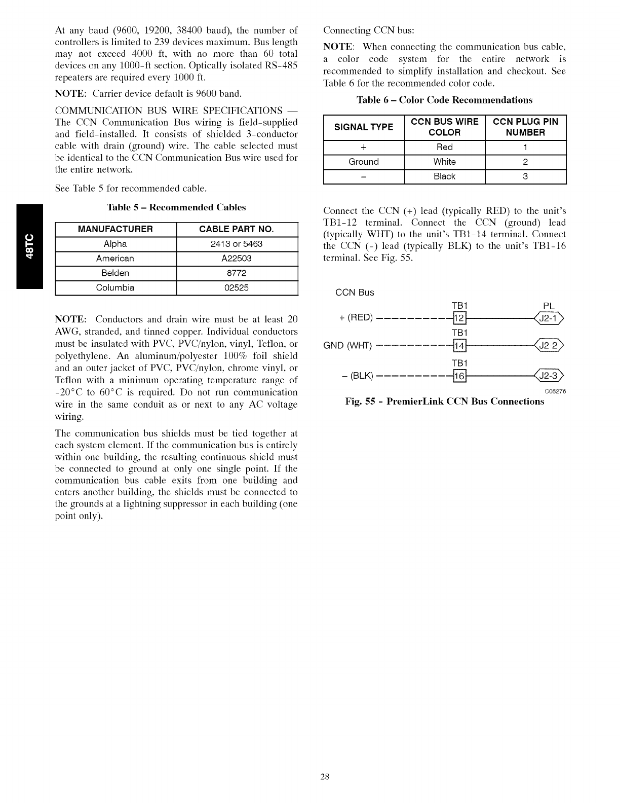
At any baud (9600, 19200, 38400 baud), the number of
controllers is limited to 239 devices maximum. Bus length
may not exceed 4000 It, with no more than 60 total
devices on any 1000-ft section. Optically isolated RS-485
repeaters are required every 1000 ft.
NOTE: Carrier device default is 9600 band.
COMMUNICATION BUS WIRE SPECIFICATIONS --
The CCN Communication Bus wiring is field-supplied
and field-installed. It consists of shielded 3-conductor
cable with drain (ground) wire. The cable selected must
be identical to the CCN Communication Bus wire used for
the entire network.
See Table 5 for recommended cable.
Table 5-Recommended Cables
MANUFACTURER CABLE PART NO.
Alpha 2413 or 5463
American A22503
Belden 8772
Columbia 02525
NOTE: Conductors and drain wire must be at least 20
AWG, stranded, and tinned copper. Individual conductors
must be insulated with PVC, PVC/nylon, vinyl, Teflon, or
polyethylene. An aluminum/polyester 100% foil shield
and an outer jacket of PVC, PVC/nylon, chrome vinyl, or
Teflon with a minimum operating temperature range of
-20°C to 60°C is required. Do not run communication
wire in the same conduit as or next to any AC voltage
wiring.
The communication bus shields must be tied together at
each system element. If the communication bus is entirely
within one building, the resulting continuous shield must
be connected to ground at only one single point. If the
communication bus cable exits from one building and
enters another building, the shields must be connected to
the grounds at a lightning suppressor in each building (one
point only).
Connecting CCN bus:
NOTE: When connecting the communication bus cable,
a color code system for the entire network is
recommended to simplify installation and checkout. See
Table 6 for the recommended color code.
Table 6-Color Code Recommendations
CCN BUS WIRE CCN PLUG PIN
SIGNAL TYPE COLOR NUMBER
+ Red 1
Ground White 2
- Black 3
Connect the CCN (+) lead (typically RED) to the unit's
TBI-12 terminal. Connect the CCN (ground) lead
(typically WHT) to the unit's TBI-14 terminal. Connect
the CCN (-) lead (typically BLK) to the unit's TBI-16
terminal. See Fig. 55.
CCN Bus
TB1 PL
+ (RED) "D
TB1
GND (WHT) '[l"_m
TB1
C08276
Fig. 55 -PremierLink CCN Bus Connections
28
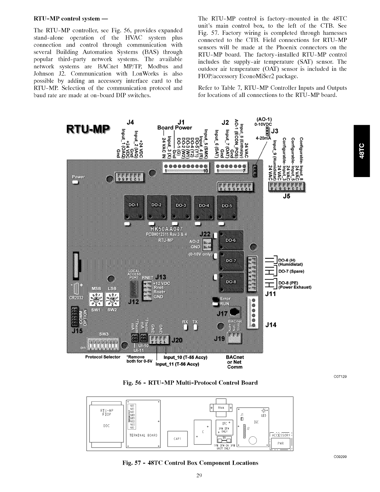
RTU-MP control system --
The RTU-MP controller, see Fig. 56, provides expanded
stand-alone operation of the HVAC system plus
connection and control through communication with
several Building Automation Systems (BAS) through
popular third-party network systems. The available
network systems are BACnet MP/TR Modbus and
Johnson J2. Communication with LonWorks is also
possible by adding an accessory interface card to the
RTU-MP. Selection of the communication protocol and
baud rate are made at on-board DIP switches.
The RTU-MP control is factory-mounted in the 48TC
unit's main control box, to the left of the CTB. See
Fig. 57. Factory wiring is completed through harnesses
connected to the CTB. Field connections for RTU-MP
sensors will be made at the Phoenix connectors on the
RTU-MP board. The factory-installed RTU-MP control
includes the supply-air temperature (SAT) sensor. The
outdoor air temperature (OAT) sensor is included in the
FIOP/accessory EconoMi$er2 package.
Refer to Table 7, RTU-MP Controller Inputs and Outputs
for locations of all connections to the RTU-MP board.
J4 J1 J2 >
o
Board Power "-
(AO-I)
0-10VDC
J3
Iv =
B B
or_ =
J5
DO_ (H)
(Humidistat)
--_J DO-7 (Spare)
DO=8 (PE)
Power Exhaust)
Jll
J14
Protocol Selector *Remove Input j0 (T-55 Accy) BACnet
both for 0-SV InpuL11 (T_ Accy) or Net
Comm
Fig. 56 -RTU-MP Multi-Protocol Control Board
C0712g
RTU-MP
FIOP
DDC
]+
+
TERMINAL BOARD
I . + UNIT 0_L¥
+
I_c_ss_S-_:
Fig. 57 -48TC Control Box Component Locations
C09299
29
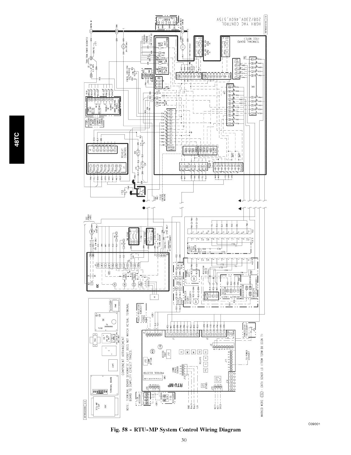
illl iii
Fig. 58 - RTU-MP System Control Wiring Diagram
3O
C09301
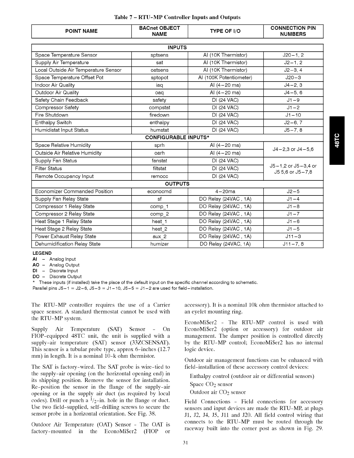
Table 7-RTU-MP Controller Inputs and Outputs
POINT NAME BACnet OBJECT TYPE OF I/O CONNECTION PIN
NAME NUMBERS
INPUTS
Space Temperature Sensor sptsens AI (10K Thermistor) J20-1,2
Supply Air Temperature sat AI (10K Thermistor) J2-1,2
Local Outside Air Temperature Sensor oatsens AI (10K Thermistor) J2-3, 4
Space Temperature Offset Pot sptopot AI (lOOK Potentiometer) J20-3
Indoor Air Quality iaq AI (4-20 ma) J4-2, 3
Outdoor Air Quality oaq AI (4-20 ma) J4-5, 6
Safety Chain Feedback safety DI (24 VAC) J1-9
Compressor Safety compstat DI (24 VAC) J1-2
Fire Shutdown firedown DI (24 VAC) J1 - 10
Enthatpy Switch enthatpy DI (24 VAC) J2-6, 7
Humidistat Input Status humstat DI (24 VAC) J5-7, 8
CONFIGURABLE INPUTS*
Space Relative Humidity sprh AI (4-20 ma) J4-2,3 or J4-5,6
Outside Air Relative Humidity oarh AI (4-20 ma)
Supply Fan Status fanstat DI (24 VAC)
Filter Status filtstat DI (24 VAC) J5-1,2 or J5-3,4 or
J5 5,6 or J5-7,8
Remote Occupancy Input remocc DI (24 VAC)
OUTPUTS
econocmd 4-20ma J2-5
sf DO Relay (24VAC, 1A) J1-4
comp_l DO Relay (24VAC, 1A) J1-8
comp_2 DO Relay (24VAC, 1A) J1-7
heat_l DO Relay (24VAC, 1A) J1-6
heat_2 DO Relay (24VAC, 1A) J1-5
aux_2 DO Relay (24VAC, 1A) J11-3
humizer DO Relay (24VAC, 1A) J11-7, 8
Economizer Commanded Position
Supply Fan Relay State
Compressor 1 Relay State
Compressor 2 Relay State
Heat Stage 1 Relay State
Heat Stage 2 Relay State
Power Exhaust Relay State
Dehumidification Relay State
LEGEND
AI - Analog Input
AO - Analog Output
DI - Discrete Input
DO - Discrete Output
* These inputs (if installed) take the place of the default input on the specific channel according to schematic.
Parallel pins J5-1 = J2-6, J5-3 = J1-10, J5-5 = J1-2 are used for field-installation.
The RTU-MP controller requires the use of a Carrier
space sensor. A standard thermostat cannot be used with
the RTU-MP system.
Supply Air Temperature (SAT) Sensor - On
FIOP-equipped 48TC unit, the unit is supplied with a
supply-air temperature (SAT) sensor (33ZCSENSAT).
This sensor is a tubular probe type, approx 6-inches (12.7
mm) in length. It is a nominal 10-k ohm thermistor.
The SAT is factory-wired. The SAT probe is wire-tied to
the supply-air opening (on the horizontal opening end) in
its shipping position. Remove the sensor for installation.
Re-position the sensor in the flange of the supply-air
opening or in the supply air duct (as required by local
codes). Drill or punch a 1/2-in. hole in the flange or duct.
Use two field-supplied, self-drilling screws to secure the
sensor probe in a horizontal orientation. See Fig. 38.
Outdoor Air Temperature (OAT) Sensor - The OAT is
factory-mounted in the EconoMi$er2 (FIOP or
accessory). It is a nominal 10k ohm thermistor attached to
an eyelet mounting ring.
EconoMi$er2 The RTU-MP control is used with
EconoMiSer2 (option or accessory) for outdoor air
management. The damper position is controlled directly
by the RTU-MP control; EconoMi$er2 has no internal
logic device.
Outdoor air management functions can be enhanced with
field-installation of these accessory control devices:
Enthalpy control (outdoor air or differential sensors)
Space CO2 sensor
Outdoor air CO2 sensor
Field Connections Field connections for accessory
sensors and input devices are made the RTU-MR at plugs
J1, J2, J4, J5, Jll and J20. All field control wiring that
connects to the RTU-MP must be routed through the
raceway built into the corner post as shown in Fig. 29.
31
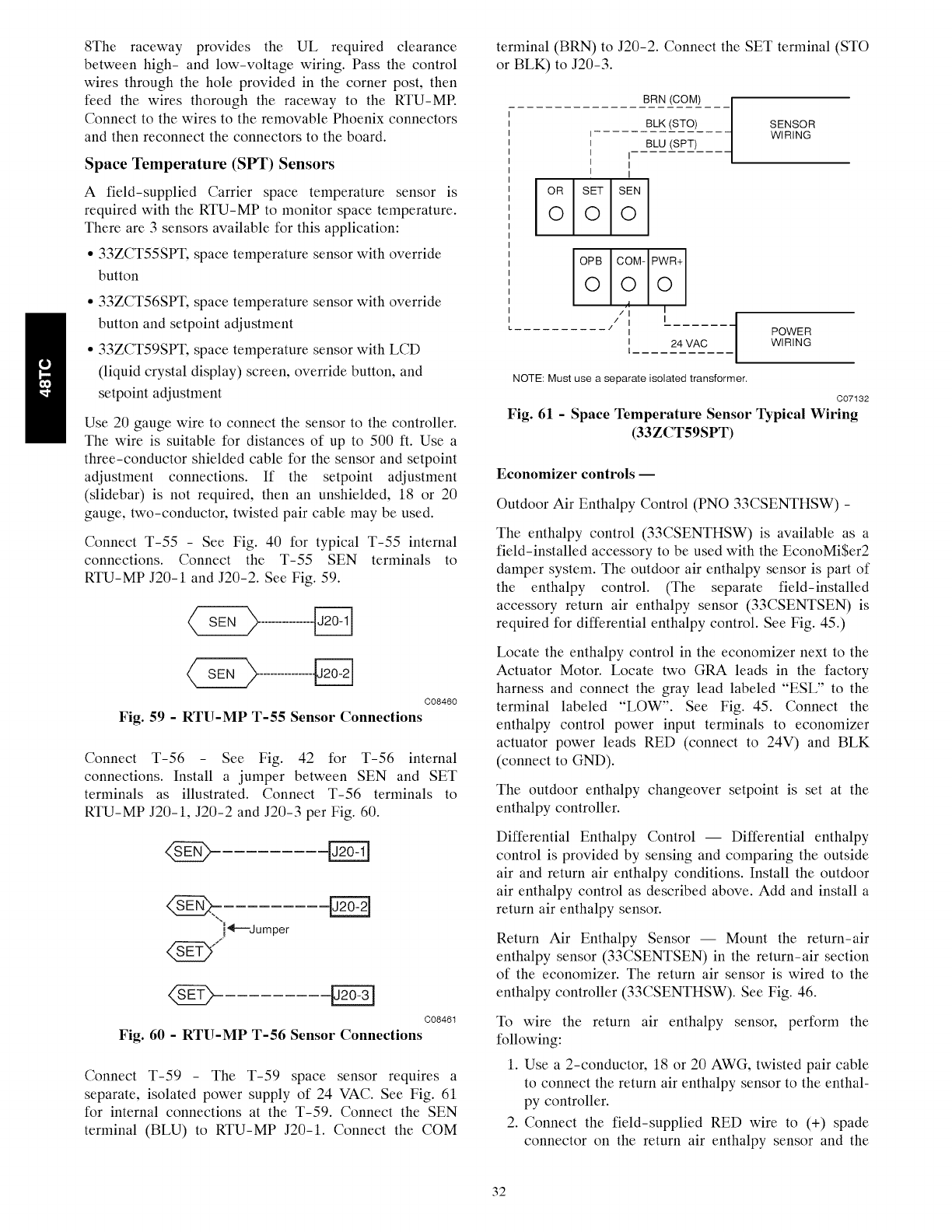
8The raceway provides the UL required clearance
between high- and low-voltage wiring. Pass the control
wires through the hole provided in the corner post, then
feed the wires thorough the raceway to the RTU-MR
Connect to the wires to the removable Phoenix connectors
and then reconnect the connectors to the board.
Space Temperature (SPT) Sensors
A field-supplied Carrier space temperature sensor is
required with the RTU-MP to monitor space temperature.
There are 3 sensors available for this application:
• 33ZCT55SPT, space temperature sensor with override
button
• 33ZCT56SPT, space temperature sensor with override
button and setpoint adjustment
• 33ZCT59SPT, space temperature sensor with LCD
(liquid crystal display) screen, override button, and
setpoint adjustment
Use 20 gauge wire to connect the sensor to the controller.
The wire is suitable for distances of up to 500 ft. Use a
three-conductor shielded cable for the sensor and setpoint
adjustment connections. If the setpoint adjustment
(slidebar) is not required, then an unshielded, 18 or 20
gauge, two-conductor, twisted pair cable may be used.
Connect T-55 -See Fig. 40 for typical T-55 internal
connections. Connect the T-55 SEN terminals to
RTU-MP J20-1 and J20-2. See Fig. 59.
C08460
Fig. 59 -RTU-MP T-55 Sensor Connections
Connect T-56 See Fig. 42 for T-56 internal
connections. Install a jumper between SEN and SET
terminals as illustrated. Connect T-56 terminals to
RTU-MP J20-1, J20-2 and J20-3 per Fig. 60.
"i,_---Jumper
C08461
Fig. 60 - RTU-MP T-56 Sensor Connections
Connect T-59 - The T-59 space sensor requires a
separate, isolated power supply of 24 VAC. See Fig. 61
for internal connections at the T-59. Connect the SEN
terminal (BLU) to RTU-MP J20-1. Connect the COM
terminal (BRN) to J20-2. Connect the SET terminal (STO
or BLK) to J20-3.
BRN (COM)
BLK (STO)
I
I BLU (SPT)
I I
I I
I I
OR SET SEN
iooo
OPB COM- PWR+
ooo
/I I
........... J I
i 24 VAC
I
SENSOR
WIRING
POWER
WIRING
NOTE: Must use a separate isolated transformer.
C07132
Fig. 61 - Space Temperature Sensor Typical Wiring
(33ZCT59SPT)
Economizer controls --
Outdoor Air Enthalpy Control (PNO 33CSENTHSW) -
The enthalpy control (33CSENTHSW) is available as a
field-installed accessory to be used with the EconoMi$er2
damper system. The outdoor air enthalpy sensor is part of
the enthalpy control. (The separate field-installed
accessory return air enthalpy sensor (33CSENTSEN) is
required for differential enthalpy control. See Fig. 45.)
Locate the enthalpy control in the economizer next to the
Actuator Motor. Locate two GRA leads in the factory
harness and connect the gray lead labeled "ESL" to the
terminal labeled "LOW". See Fig. 45. Connect the
enthalpy control power input terminals to economizer
actuator power leads RED (connect to 24V) and BLK
(connect to GND).
The outdoor enthalpy changeover setpoint is set at the
enthalpy controller.
Differential Enthalpy Control -- Differential enthalpy
control is provided by sensing and comparing the outside
air and return air enthalpy conditions. Install the outdoor
air enthalpy control as described above. Add and install a
return air enthalpy sensor.
Return Air Enthalpy Sensor -- Mount the return-air
enthalpy sensor (33CSENTSEN) in the return-air section
of the economizer. The return air sensor is wired to the
enthalpy controller (33CSENTHSW). See Fig. 46.
To wire the return air enthalpy sensor, perform the
following:
1. Use a 2-conductor, 18 or 20 AWG, twisted pair cable
to connect the return air enthalpy sensor to the enthal-
py controller.
2. Connect the field-supplied RED wire to (+) spade
connector on the return air enthalpy sensor and the
32
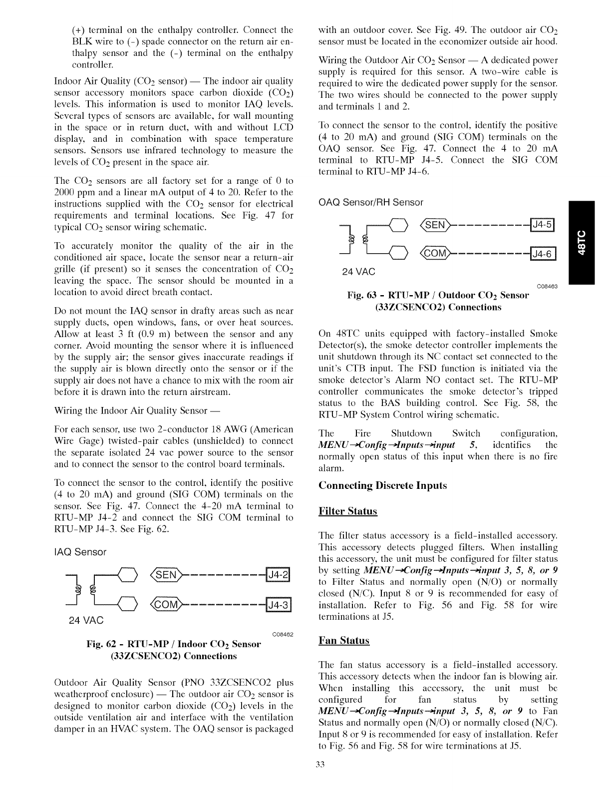
(+) terminal on the enthalpy controller. Connect the
BLK wire to (-) spade connector on the return air en-
thalpy sensor and the (-) terminal on the enthalpy
controller.
Indoor Air Quality (CO 2 sensor) -- The indoor air quality
sensor accessory monitors space carbon dioxide (CO2)
levels. This information is used to monitor IAQ levels.
Several types of sensors are available, for wall mounting
in the space or in return duct, with and without LCD
display, and in combination with space temperature
sensors. Sensors use infrared technology to measure the
levels of CO2 present in the space air.
The CO2 sensors are all factory set for a range of 0 to
2000 ppm and a linear mA output of 4 to 20. Refer to the
instructions supplied with the CO2 sensor for electrical
requirements and terminal locations. See Fig. 47 for
typical CO2 sensor wiring schematic.
To accurately monitor the quality of the air in the
conditioned air space, locate the sensor near a return-air
grille (if present) so it senses the concentration of CO2
leaving the space. The sensor should be mounted in a
location to avoid direct breath contact.
Do not mount the IAQ sensor in drafty areas such as near
supply ducts, open windows, fans, or over heat sources.
Allow at least 3 ft (0.9 m) between the sensor and any
corner. Avoid mounting the sensor where it is influenced
by the supply air; the sensor gives inaccurate readings if
the supply air is blown directly onto the sensor or if the
supply air does not have a chance to mix with the room air
before it is drawn into the return airstream.
Wiring the Indoor Air Quality Sensor --
For each sensor, use two 2-conductor 18 AWG (American
Wire Gage) twisted-pair cables (unshielded) to connect
the separate isolated 24 vac power source to the sensor
and to connect the sensor to the control board terminals.
To connect the sensor to the control, identify the positive
(4 to 20 mA) and ground (SIG COM) terminals on the
sensor. See Fig. 47. Connect the 4-20 mA terminal to
RTU-MP J4-2 and connect the SIG COM terminal to
RTU-MP J4-3. See Fig. 62.
IAQ Sensor
24 VAC
C08462
Fig. 62 - RTU-MP /Indoor CO 2 Sensor
(33ZCSENCO2) Connections
Outdoor Air Quality Sensor (PNO 33ZCSENCO2 plus
weatherproof enclosure) -- The outdoor air CO2 sensor is
designed to monitor carbon dioxide (CO2) levels in the
outside ventilation air and interface with the ventilation
damper in an HVAC system. The OAQ sensor is packaged
with an outdoor cover. See Fig. 49. The outdoor air CO2
sensor must be located in the economizer outside air hood.
Wiring the Outdoor Air CO2 Sensor -- A dedicated power
supply is required for this sensor. A two-wire cable is
required to wire the dedicated power supply for the sensor.
The two wires should be connected to the power supply
and terminals 1 and 2.
To connect the sensor to the control, identify the positive
(4 to 20 mA) and ground (SIG COM) terminals on the
OAQ sensor. See Fig. 47. Connect the 4 to 20 mA
terminal to RTU-MP J4-5. Connect the SIG COM
terminal to RTU-MP J4-6.
OAQ Sensor/Fill Sensor
24 VAC
C08463
Fig. 63 - RTU-MP /Outdoor CO 2 Sensor
(33ZCSENCO2) Connections
On 48TC units equipped with factory-installed Smoke
Detector(s), the smoke detector controller implements the
unit shutdown through its NC contact set connected to the
unit's CTB input. The FSD function is initiated via the
smoke detector's Alarm NO contact set. The RTU-MP
controller communicates the smoke detector's tripped
status to the BAS building control. See Fig. 58, the
RTU-MP System Control wiring schematic.
The Fire Shutdown Switch configuration,
MENU _Config-_Inputs-+input 5, identifies the
normally open status of this input when there is no fire
alarm.
Connecting Discrete Inputs
Filter Status
The filter status accessory is a field-installed accessory.
This accessory detects plugged filters. When installing
this accessory, the unit must be configured for filter status
by setting MENU--_onfig-_Inputs-,qnput 3, 5, 8, or 9
to Filter Status and normally open (N/O) or normally
closed (N/C). Input 8 or 9 is recommended for easy of
installation. Refer to Fig. 56 and Fig. 58 for wire
terminations at J5.
Fan Status
The fan status accessory is a field-installed accessory.
This accessory detects when the indoor fan is blowing air.
When installing this accessory, the unit must be
configured for fan status by setting
MENU-_onfig-_Inputs-+input 3, 5, 8, or 9 to Fan
Status and normally open (N/O) or normally closed (N/C).
Input 8 or 9 is recommended for easy of installation. Refer
to Fig. 56 and Fig. 58 for wire terminations at J5.
33
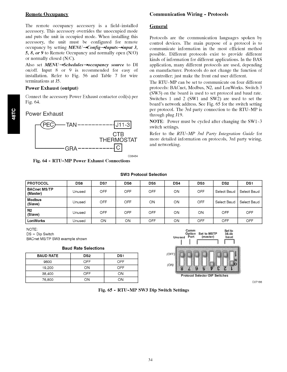
Remote Occupancy Communication Wiring - Protocols
The remote occupancy accessory is a field-installed
accessory. This accessory overrides the unoccupied mode
and puts the unit in occupied mode. When installing this
accessory, the unit must be configured for remote
occupancy by setting MENU_Config-Hnputs--,input 3,
5, 8, or 9 to Remote Occupancy and normally open (N/O)
or normally closed (N/C).
Also set MENU--_Schedules--_occupancy source to DI
on/off. Input 8 or 9 is recommended for easy of
installation. Refer to Fig. 56 and Table 7 for wire
terminations at J5.
Power Exhaust (output)
Connect the accessory Power Exhaust contactor coil(s) per
Fig. 64.
Power Exhaust
TAN
CTB
THERMOSTAT
GRA
C08464
Fig. 64 -RTU-MP Power Exhaust Connections
General
Protocols are the communication languages spoken by
control devices. The main purpose of a protocol is to
communicate information in the most efficient method
possible. Different protocols exist to provide different
kinds of information for different applications. In the BAS
application, many different protocols are used, depending
on manufacturer. Protocols do not change the function of
a controller; just make the front end user different.
The RTU-MP can be set to communicate on four different
protocols: BACnet, Modbus, N2, and LonWorks. Switch 3
(SW3) on the board is used to set protocol and baud rate.
Switches 1 and 2 (SWl and SW2) are used to set the
board's network address. See Fig. 65 for the switch setting
per protocol. The 3rd party connection to the RTU-MP is
through plug J19.
NOTE: Power must be cycled after changing the SW1-3
switch settings.
Refer to the RTU-MP 3rd Part)' Integration Guide for
more detailed information on protocols, 3rd party wiring,
and networking.
SW3 Protocol Selection
PROTOCOL DS8 DS7 DS6 DS5 DS4 DS3 DS2 DS1
BACnet MS/'FP Unused OFF OFF OFF ON OFF Select Baud Select Baud
(Master)
Modbus Unused OFF OFF ON ON OFF Select Baud Select Baud
(Slave)
N2 Unused OFF OFF OFF ON ON OFF OFF
(Slave)
LonWorks Unused ON ON OFF ON OFF OFF OFF
NOT E: C_a_ _(
DS = Dip Switch O_t_ S_ _ NSTP 3&4_
BAOnet MS/TP SW6 example shown j J [ i
Baud Rate Selections
BAUD RATE DS2 DS1
9600 OFF OFF
19,200 ON OFF
38,400 OFF ON
76,800 ON ON
Fig. 65 - RTU-MP SW3 Dip Switch Settings
C07166
34
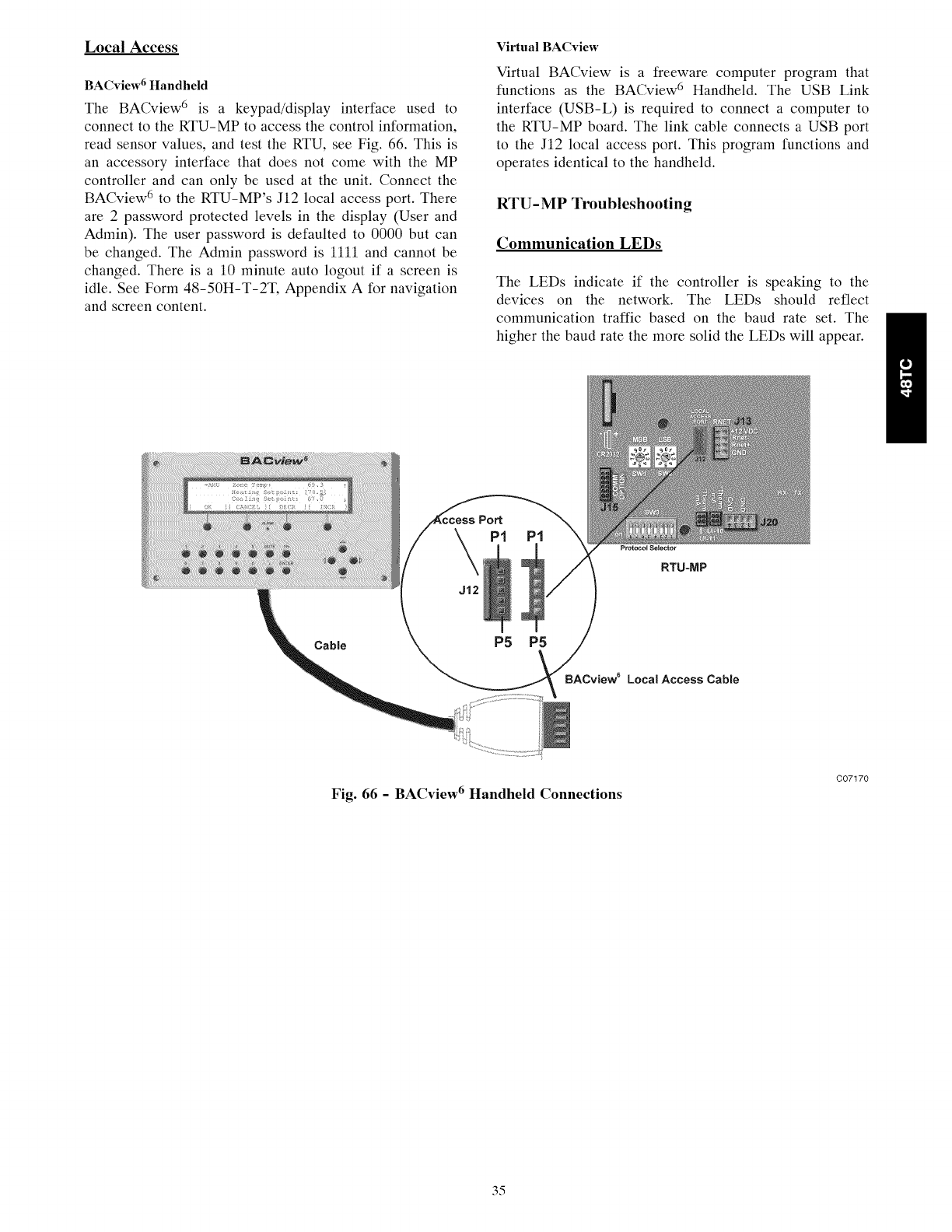
Local Access
BACview 6 Handheld
The BACview 6 is a keypad/display interface used to
connect to the RTU-MP to access the control information,
read sensor values, and test the RTU, see Fig. 66. This is
an accessory interface that does not come with the MP
controller and can only be used at the unit. Connect the
BACview 6 to the RTU-MP's J12 local access port. There
are 2password protected levels in the display (User and
Admin). The user password is defaulted to 0000 but can
be changed. The Admin password is 1111 and cannot be
changed. There is a 10 minute auto logout if a screen is
idle. See Form 48-50H-T-2T, Appendix A for navigation
and screen content.
Virtual BACview
Virtual BACview is a freeware computer program that
functions as the BACview 6 Handheld. The USB Link
interface (USB-L) is required to connect a computer to
the RTU-MP board. The link cable connects a USB port
to the J12 local access port. This program functions and
operates identical to the handheld.
RTU-MP Troubleshooting
Communication LEDs
The LEDs indicate if the controller is speaking to the
devices on the network. The LEDs should reflect
communication traffic based on the baud rate set. The
higher the baud rate the more solid the LEDs will appear.
Port
P1
J12
PI
Protocol Selector
RTU-MP
Cable P5 P5
BACview sLoca| Access CaNe
Fig. 66 -BACview 6 Handheld Connections
C07170
35
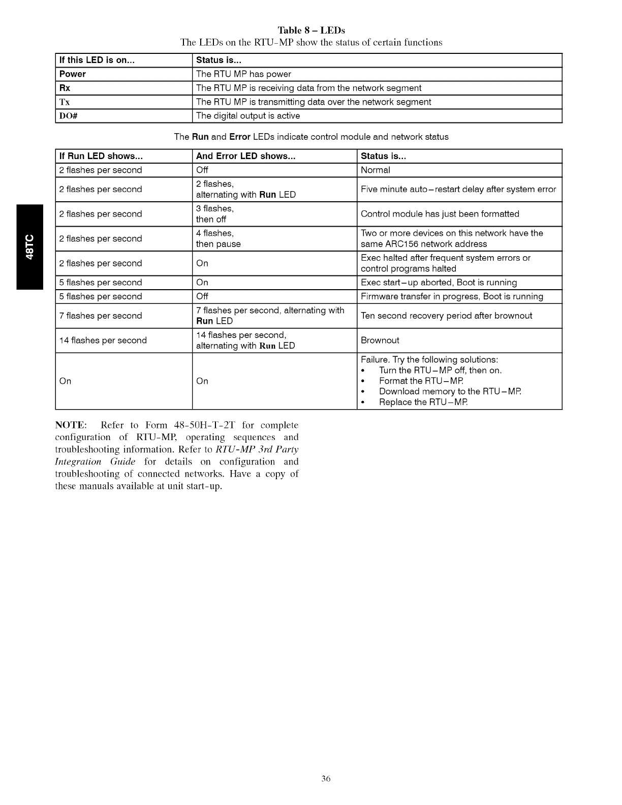
Table 8-LEDs
The LEDs on the RTU-MP show the status of certain functions
If this LED is on... Status is...
Power The RTU MP has power
Rx The RTU MP is receiving data from the network segment
Tx The RTU MP is transmitting data over the network segment
DO# The digital output is active
The Run and Error LEDs indicate control module and network status
If Run LED shows... And Error LED shows... Status is...
2 flashes per second Off Normal
2 flashes,
2 flashes per second alternating with Run LED Five minute auto-restart delay after system error
3 flashes, Control module has just been formatted
2 flashes per second then off
4 flashes, Two or more devices on this network have the
2 flashes per second then pause same ARC156 network address
Exec halted after frequent system errors or
2 flashes per second On control programs halted
5 flashes per second On Exec start-up aborted, Boot is running
5 flashes per second Off Firmware transfer in progress, Boot is running
7 flashes per second 7 flashes per second, alternating with Ten second recovery period after brownout
Run LED
14 flashes per second, Brownout
14 flashes per second alternating with Run LED
On On
Failure. Try the following solutions:
• Turn the RTU-MP off, then on.
• Format the RTU- MR
• Download memory to the RTU-MR
• Replace the RTU- MR
NOTE: Refer to Form 48-50H-T-2T for complete
configuration of RTU-ME operating sequences and
troubleshooting information. Refer to RTU-MP 3rd Party
Integration Guide for details on configuration and
troubleshooting of connected networks. Have a copy of
these manuals available at unit start-up.
36
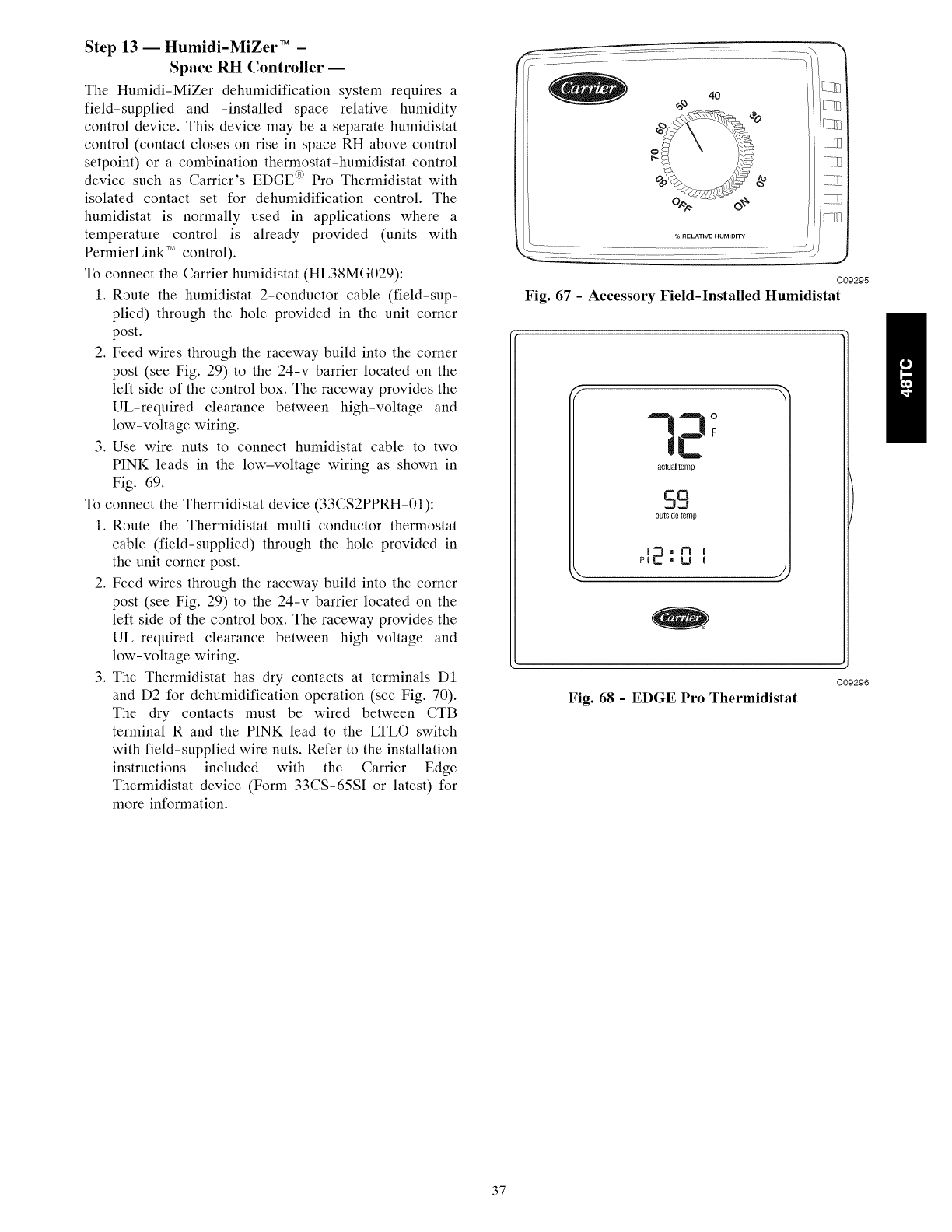
Step 13 -- Humidi-MiZer TM -
Space RH Controller --
The Humidi-MiZer dehumidification system requires a
field-supplied and -installed space relative humidity
control device. This device may be aseparate humidistat
control (contact closes on rise in space RH above control
setpoint) or a combination thermostat-humidistat control
device such as Carrier's EDGE (n_Pro Thermidistat with
isolated contact set for dehumidification control. The
humidistat is normally used in applications where a
temperature control is already provided (units with
PermierLink TM control).
To connect the Carrier humidistat (HL38MG029):
1. Route the humidistat 2-conductor cable (field-sup-
plied) through the hole provided in the unit corner
post.
2. Feed wires through the raceway build into the corner
post (see Fig. 29) to the 24-v barrier located on the
left side of the control box. The raceway provides the
UL-required clearance between high-voltage and
low-voltage wiring.
3. Use wire nuts to connect humidistat cable to two
PINK leads in the low-voltage wiring as shown in
Fig. 69.
To connect the Thermidistat device (33CS2PPRH-01):
1. Route the Thermidistat multi-conductor thermostat
cable (field-supplied) through the hole provided in
the unit corner post.
2. Feed wires through the raceway build into the corner
post (see Fig. 29) to the 24-v barrier located on the
left side of the control box. The raceway provides the
UL-required clearance between high-voltage and
low-voltage wiring.
3. The Thermidistat has dry contacts at terminals DI
and D2 for dehumidification operation (see Fig. 70).
The dry contacts must be wired between CTB
terminal R and the PINK lead to the LTLO switch
with field-supplied wire nuts. Refer to the installation
instructions included with the Carrier Edge
Thermidistat device (Form 33CS-65SI or latest) for
more information.
4O
_o E-31-
L:IT
LL
C09295
Fig. 67 - Accessory Field-Installed Humidistat
IC
actualtemp
59
outside temp
P _mU I
Fig. 68 -EDGE Pro Thermidistat
C09296
37
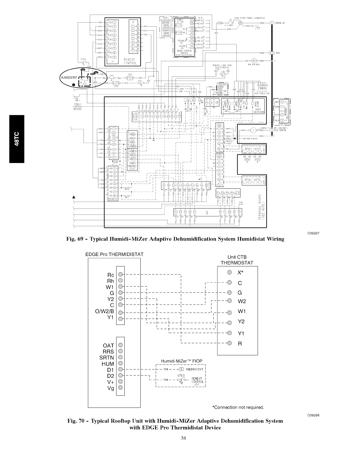
r,_m
CONTROL i
WIRING
r
_ __ ,_HT
P,4K
YEL
_LU
WH
_H
A
%
}
%
(}
:i.... I
FC (PH OL}
CLOlTERMBB
Fig. 69 -Typical Humidi-MiZer Adaptive Dehumidification System Humidistat Wiring
C09297
EDGE Pro THERMIDISTAT
Rc ....
Rh Q
Wl ....
G ....
Y2 .........
C ....
O/W2/B ....
Y1 ....
OAT Q
RRS Q
SRTN @
HUM @
D1 ....
D2
V+
Vg
I
l q
I
I I
l H 1
I I
I I
_ l l ll 1
I I
-- i-
___4__
I
I
Unit CTB
THERMOSTAT
Q X*
i...... _ C
I
I
]-- l Q G
I
l I ---- W2
I
Wl
I
I
I_ Y2
_1
Y1
-- R
HumidilMiZer TM FlOP
I............................ 7
'
..... PNI_ I l _ THERMOSTAT i
q i LTLO i
-i- -PNK -- -- <_1/'o _ REHEAT I
'_ CONTROL
I...................... u__J
*Connection not required.
Fig. 70 -Typical Rooftop Unit with Humidi-MiZer Adaptive Dehumidification System
with EDGE Pro Thermidistat Device
C09298
38
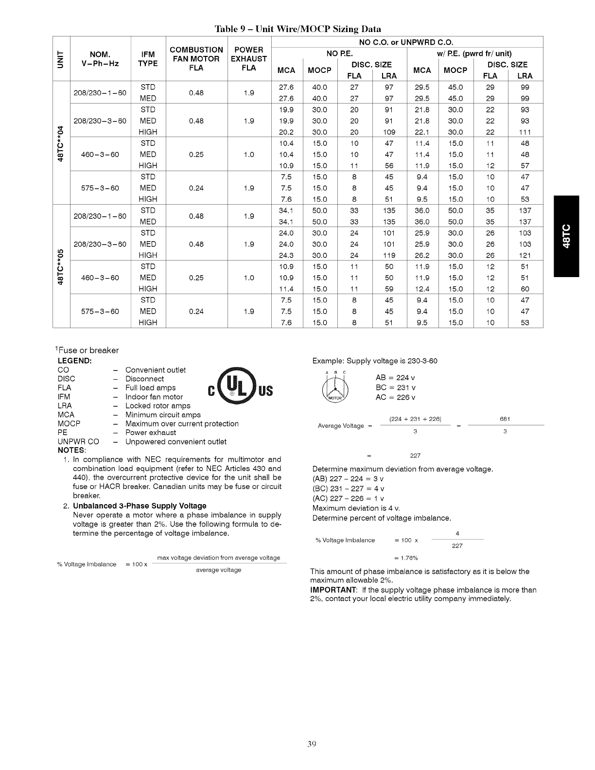
---- NOM. IFM FANMOTOR
V-Ph-Hz TYPE FLA
Table 9 -Unit Wire/MOCP Sizing Data
NO C.O. or UNPWRD C.O.
COMBUSTION POWER NORE. w/RE, (pwrdfr/unit)
DISC. SIZE
EXHAUST
FLA
1.9
1.9
1.0
1.9
1.9
1.9
1.0
1.9
MCA
27.6
27.6
19.9
19.9
20.2
10.4
10.4
10.9
7.5
7.5
7.6
34.1
34.1
24.0
24.0
24.6
10.9
10.9
11.4
7.5
7.5
7.6
DISC. SIZE
MOCP FLA LRA
40.0 27 97
40.0 27 97
30.0 20 91
30.0 20 91
30.0 20 109
15.0 10 47
15.0 10 47
15.0 11 56
15.0 8 45
15.0 8 45
15.0 8 51
50.0 33 135
50.0 33 135
30.0 24 101
30.0 24 101
30.0 24 119
15.0 11 50
15.0 11 50
15.0 11 59
15.0 8 45
15.0 8 45
15.0 8 51
MCA
29.5
29.5
21.8
21.8
22.1
11.4
11.4
11.9
9.4
9.4
9.5
36.0
36.0
25.9
25.9
26.2
11.9
11.9
12.4
9.4
9.4
9.5
MOCP
45.0
45.0
30.0
30.0
30.0
15.0
15.0
15.0
15.0
15.0
15.0
50.0
50.0
30.0
30.0
30.0
15.0
15.0
15.0
15.0
15.0
15.0
STD
208/260-1 - 60 0.48
MED
STD
208/260- 3- 60 MED 0.48
o HIGH
-k
O STD
460-6-60 MED 0.25
HIGH
STD
575-6-60 MED 0.24
HIGH
STD
208/260-1 - 60 0.48
MED
STD
208/260- 3- 60 MED 0.48
It)
o HIGH
-k
O STD
460-6-60 MED 0.25
HIGH
STD
575-6-60 MED 0.24
HIGH
FLA LRA
29 99
29 99
22 96
22 96
22 111
11 48
11 48
12 57
10 47
10 47
10 53
35 137
35 137
26 103
26 103
26 121
12 51
12 51
12 60
10 47
10 47
10 53
1Fuse or breaker
LEGEND:
CO -Convenient outlet v Q US
DISC - Disconnect
FLA -Full load amps
IFM - Indoor fan motor
LRA - Locked rotor amps
MCA - Minimum circuit amps
MOCP - Maximum over current protection
PE - Power exhaust
UNPWR CO - Unpowered convenient outlet
NOTES:
1. In compliance with NEC requirements for multimotor and
combination load equipment (refer to NEC Articles 430 and
440), the overcurrent protective device for the unit shall be
fuse or HACR breaker. Canadian units may be fuse or circuit
breaker.
2. Unbalanced 3-Phase Supply Voltage
Never operate a motor where a phase imbalance in supply
voltage is greater than 2%. Use the following formula to de-
termine the percentage of voltage imbalance.
max voltage deviation from average voltage
% Voltage imbalance = 1O0 x average voltage
Example: Supply voltage is 260-3-60
AB = 224 v
BC = 231 v
AC = 226 v
(224 + 231 + 226)
Average Voltage = 3
681
=3
= 227
Determine maximum deviation from average voltage.
(AB) 227 - 224 = 3 v
(BC) 261 - 227 = 4 v
(AC) 227- 226 = 1 v
Maximum deviation is 4 v.
Determine percent of voltage imbalance.
4
% Voltage imbalance = 100 x 227
= 1.76%
This amount of phase imbalance is satisfactory as it is below the
maximum allowable 2%.
IMPORTANT: If the supply voltage phase imbalance is more than
2%, contact your local electric utility company immediately.
39
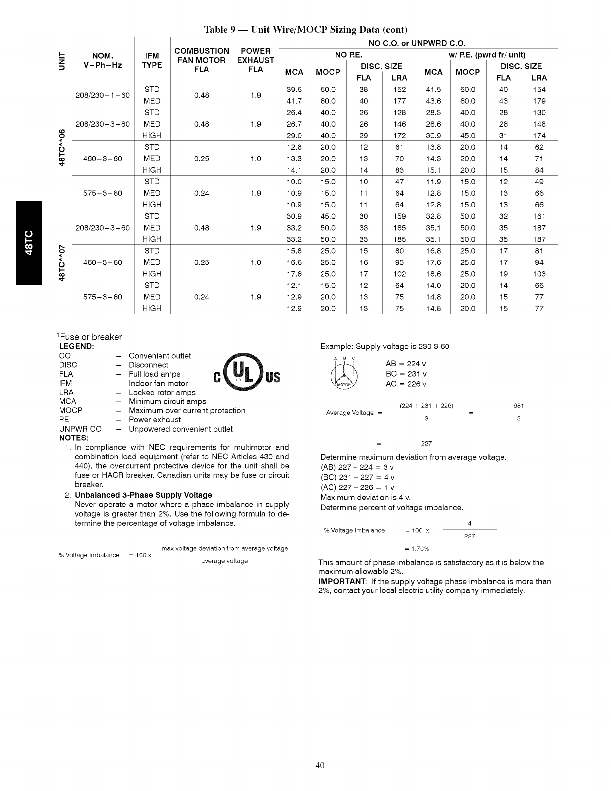
(D
?
-k
O
NOM. IFM FAN MOTOR
V-Ph-Hz TYPE FLA
Table 9 -- Unit Wire/MOCP Sizing Data (cont)
NO C.O. or UNPWRD C.O.
COMBUSTION POWER NORE. w/RE, (pwrdfr/unit)
DISC. SIZE
EXHAUST
FLA
1.9
1.9
1.0
1.9
1.9
1.0
1.9
MCA
69.6
41.7
26.4
26.7
29.0
12.8
13.6
14.1
10.0
10.9
10.9
30.9
33.2
33.2
15.8
16.6
17.6
12.1
12.9
12.9
DISC. SIZE
MOCP FLA LRA
60.0 68 152
60.0 40 177
40.0 26 128
40.0 26 146
40.0 29 172
20.0 12 61
20.0 16 70
20.0 14 86
15.0 10 47
15.0 11 64
15.0 11 64
45.0 30 159
50.0 33 185
50.0 33 185
25.0 15 80
25.0 16 96
25.0 17 102
15.0 12 64
20.0 16 75
20.0 16 75
MCA
41.5
46.6
28.6
28.6
30.9
16.8
14.6
15.1
11.9
12.8
12.8
32.8
35.1
35.1
16.8
17.6
18.6
14.0
14.8
14.8
MOCP
60.0
60.0
40.0
40.0
45.0
20.0
20.0
20.0
15.0
15.0
15.0
50.0
50.0
50.0
25.0
25.0
25.0
20.0
20.0
20.0
STD
208/260-1 - 60 0.48
MED
STD
208/260- 6- 60 MED 0.48
HIGH
STD
460-6-60 MED 0.25
HIGH
STD
575-6-60 MED 0.24
HIGH
STD
208/260- 6- 60 MED 0.48
HIGH
STD
460-6-60 MED 0.25
HIGH
STD
575-6-60 MED 0.24
HIGH
FLA LRA
40 154
46 179
28 130
28 148
61 174
14 62
14 71
15 84
12 49
13 66
13 66
32 161
35 187
35 187
17 81
17 94
19 103
14 66
15 77
15 77
1Fuse or breaker
LEGEND:
CO -Convenient outlet v Q US
DISC - Disconnect
FLA - Full load amps
IFM - Indoor fan motor
LRA - Locked rotor amps
MCA - Minimum circuit amps
MOCP - Maximum over current protection
PE - Power exhaust
UNPWR CO - Unpowered convenient outlet
NOTES:
1. In compliance with NEC requirements for multimotor and
combination load equipment (refer to NEC Articles 430 and
440), the overcurrent protective device for the unit shall be
fuse or HACR breaker. Canadian units may be fuse or circuit
breaker.
2. Unbalanced 3-Phase Supply Voltage
Never operate a motor where a phase imbalance in supply
voltage is greater than 2%. Use the following formula to de-
termine the percentage of voltage imbalance.
max voltage deviation from average voltage
% Voltage imbalance = 100 x average voltage
Example: Supply voltage is 260-3-60
AB =224 v
BC = 261 v
AC = 226 v
(224 + 231 + 226)
Average Voltage = 3
681
=3
= 227
Determine maximum deviation from average voltage.
(AB) 227 - 224 =3 v
(BC) 261 - 227 =4 v
(AC) 227- 226 =1 v
Maximum deviation is 4 v.
Determine percent of voltage imbalance.
4
% Voltage imbalance = 100 x 227
= 1.76%
This amount of phase imbalance is satisfactory as it is below the
maximum allowable 2%.
IMPORTANT: If the supply voltage phase imbalance is more than
2%, contact your local electric utility company immediately.
40

I-- NOM. IFM FAN MOTOR
V-Ph-Hz TYPE FLA
208/230-1 -60
208/230- 3- 60
?
460- 3- 60
575- 3- 60
208/230-1 - 60
208/230- 3- 60
It)
?
460- 3- 60
575- 3- 60
Table 9 -- Unit Wire/MOCP Sizing Data (cont)
w/PWRD C.O.
COMBUSTION POWER NO RE.
EXHAUST
FLA
1.9
1.9
1.0
1.9
1.9
1.9
1.0
1.9
MCA
32.4
32.4
24.7
24.7
25.0
12.6
12.6
13.1
9.2
9.2
9.3
38.9
38.9
28.8
28.8
29.1
13.1
13.1
13.6
9.2
9.2
9.3
DISC. SIZE
MOCP FLA LRA
45.0 33 102
45.0 33 102
30.0 25 96
30.0 25 96
30.0 26 114
15.0 13 49
15.0 13 49
15.0 13 58
15.0 9 47
15.0 9 47
15.0 10 53
60.0 39 140
60.0 39 140
40.0 29 106
40.0 29 106
40.0 30 124
15.0 13 52
15.0 13 52
20.0 14 61
15.0 9 47
15.0 9 47
15.0 10 53
MCA
34.3
34.3
26.6
26.6
26.9
13.6
13.6
14.1
11.1
11.1
11.2
40.8
40.8
30.7
30.7
31.0
14.1
14.1
14.6
11.1
11.1
11.2
w/RE. (pwrd fr/unit)
DISC. SIZE
MOCP FLA LRA
50.0 35 104
50.0 35 104
30.0 28 98
30.0 28 98
30.0 28 116
20.0 14 50
20.0 14 50
20.0 15 59
15.0 12 49
15.0 12 49
15.0 12 55
60.0 41 142
60.0 41 142
40.0 31 108
40.0 31 108
40.0 32 126
20.0 14 53
20.0 14 53
20.0 15 62
15.0 12 49
15.0 12 49
15.0 12 55
STD 0.48
MED
STD
MED 0.48
HIGH
STD
MED 0.25
HIGH
STD
MED 0.24
HIGH
STD 0.48
MED
STD
MED 0.48
HIGH
STD
MED 0.25
HIGH
STD
MED 0.24
HIGH
1Fuse or breaker
LEGEND:
CO
DISC
FLA
IFM
LRA
MCA
MOCP
PE
UNPWR CO -
NOTES:
Example: Supply voltage is 230-3-60
C°nvenient°utlet QUS _
Disconnect AB = 224 v
Full load amps C BC = 231 v
Indoor fan motor AC = 226 v
Locked rotor amps
Minimum circuit amps (224 + 231 +226)
Maximum over current protection Average Voltage =
Power exhaust 3
Unpowered convenient outlet
1. In compliance with NEC requirements for multimotor and
combination load equipment (refer to NEC Articles 430 and
440), the overcurrent protective device for the unit shall be
fuse or HACR breaker. Canadian units may be fuse or circuit
breaker.
2. Unbalanced 3-Phase Supply Voltage
Never operate a motor where a phase imbalance in supply
voltage is greater than 2%. Use the following formula to de-
termine the percentage of voltage imbalance.
max voltage deviation from average voltage
% Voltage imbalance = 1O0 x average voltage
681
=3
= 227
Determine maximum deviation from average voltage.
(AB) 227 - 224 = 3 v
(BC) 231 - 227 = 4 v
(AC) 227- 226 = 1 v
Maximum deviation is 4 v.
Determine percent of voltage imbalance.
4
% Voltage imbalance = 100 x 227
= 1.76%
This amount of phase imbalance is satisfactory as it is below the
maximum allowable 2%.
IMPORTANT: If the supply voltage phase imbalance is more than
2%, contact your local electric utility company immediately.
41
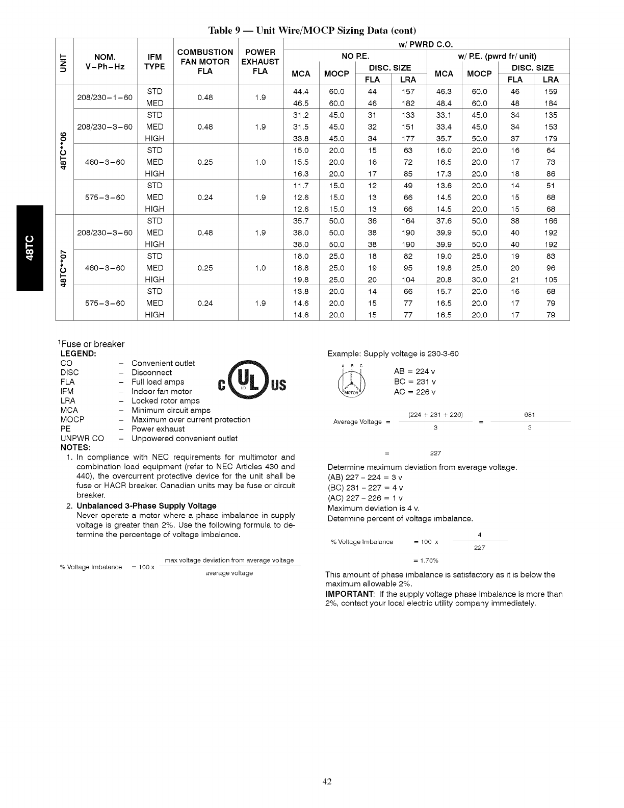
_D
?
-k
0
NOM.
V-Ph-Hz
IFM FAN MOTOR
TYPE FLA
Table 9 -- Unit Wire/MOCP Sizing Data (cont)
w/PWRD C.O.
COMBUSTION POWER NO RE.
EXHAUST
FLA
1.9
1.9
1.0
1.9
1.9
1.0
1.9
MCA
44.4
46.5
31.2
31.5
36.8
15.0
15.5
16.6
11.7
12.6
12.6
35.7
38.0
38.0
18.0
18.8
19.8
13.8
14.6
14.6
DISC. SIZE
MOCP FLA LRA
60.0 44 157
60.0 46 182
45.0 31 133
45.0 32 151
45.0 34 177
20.0 15 63
20.0 16 72
20.0 17 85
15.0 12 49
15.0 13 66
15.0 13 66
50.0 36 164
50.0 38 190
50.0 38 190
25.0 18 82
25.0 19 95
25.0 20 104
20.0 14 66
20.0 15 77
20.0 15 77
MCA
46.3
48.4
33.1
33.4
35.7
16.0
16.5
17.3
13.6
14.5
14.5
37.6
39.9
39.9
19.0
19.8
20.8
15.7
16.5
16.5
w/RE. (pwrd fr/unit)
DISC. SIZE
MOCP FLA LRA
60.0 46 159
60.0 48 184
45.0 34 165
45.0 34 156
50.0 67 179
20.0 16 64
20.0 17 76
20.0 18 86
20.0 14 51
20.0 15 68
20.0 15 68
50.0 68 166
50.0 40 192
50.0 40 192
25.0 19 86
25.0 20 96
60.0 21 105
20.0 16 68
20.0 17 79
20.0 17 79
STD
208/260-1 - 60 0.48
MED
STD
208/260- 3- 60 MED 0.48
HIGH
STD
460-6-60 MED 0.25
HIGH
STD
575-6-60 MED 0.24
HIGH
STD
208/260- 3- 60 MED 0.48
HIGH
STD
460-6-60 MED 0.25
HIGH
STD
575-6-60 MED 0.24
HIGH
1Fuse or breaker
LEGEND:
CO
DISC
FLA
IFM
LRA
MCA
MOCP
PE
UNPWR CO -
NOTES:
Example: Supply voltage is 260-3-60
C°nvenient°utlet QUS _
Disconnect AB = 224 v
Full load amps CBC = 231 v
Indoor fan motor AC = 226 v
Locked rotor amps
Minimum circuit amps (224 + 231 +226)
Maximum over current protection Average Voltage =
Power exhaust 3
Unpowered convenient outlet
1. In compliance with NEC requirements for multimotor and
combination load equipment (refer to NEC Articles 430 and
440), the overcurrent protective device for the unit shall be
fuse or HACR breaker. Canadian units may be fuse or circuit
breaker.
2. Unbalanced 3-Phase Supply Voltage
Never operate a motor where a phase imbalance in supply
voltage is greater than 2%. Use the following formula to de-
termine the percentage of voltage imbalance.
max voltage deviation from average voltage
% Voltage imbalance = 1O0 x average voltage
681
=3
= 227
Determine maximum deviation from average voltage.
(AB) 227 - 224 = 3 v
(BC) 261 - 227 = 4 v
(AC) 227- 226 = 1 v
Maximum deviation is 4 v.
Determine percent of voltage imbalance.
4
% Voltage imbalance = 100 x 227
= 1.76%
This amount of phase imbalance is satisfactory as it is below the
maximum allowable 2%.
IMPORTANT: If the supply voltage phase imbalance is more than
2%, contact your local electric utility company immediately.
42
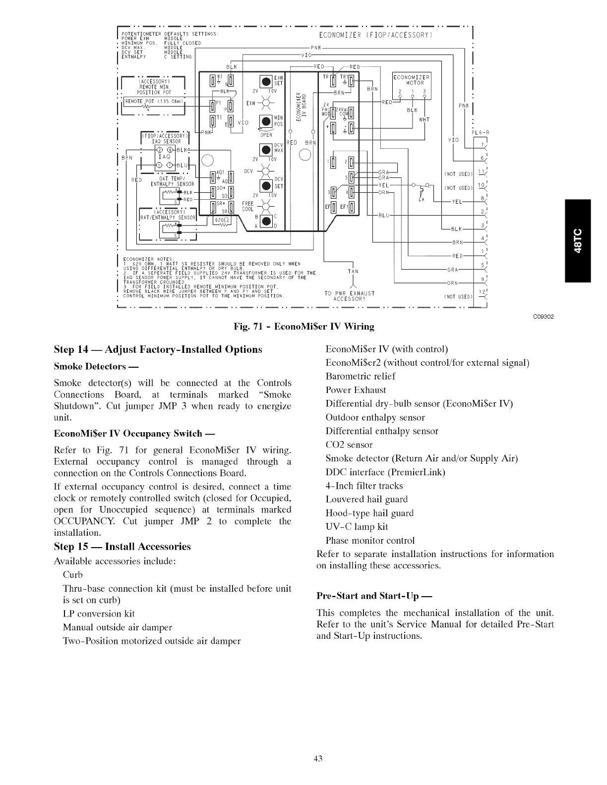
POTENTIOMETER DEFAULTS SETTINGS:
POWER EXH MIDDLE
MINIMUM POS FULLY CLOSED
DCV MAX MIDDLE
DCV SET MIDDLE
ENTHALPY C SETTING
I (ACCESSORY) 1
REMOTE MIN
POSITION POT
_rF_SA_C_Ri;
AO SENSOR
BLU F
"OATTE--'%7
E,_,ALPYSERSOR
BLK --RED
IRAT/ENTHALPY SENSOF
B'L,
.pNK_ TI T_
EXH
SET
2V IOV
NIN0 POS
T-_--J-
OPE_
DCV
MAX
SO 2V I OV
COOL
o c
ECONOMIZER
PNI<
VEO-
[D B
ECONOMIZER NOTES:
l 620 OHM, l WATT 5% RESISTER SHOULD BE REMOVED ONLY WHEN --I
USING DIFFERENTIAL ENTHALPY OR DRY BULB i
2 IF A SEPERATE FIELD SUPPLIED 24V TRANSFORMER IS USED FOR THE TAN
IAO SENSOR POWER SUPPLY, IT CANNOT HAVE THE SECONDARY OF THE I
TRANSFORMER GROUNDED A
3 FOR FIELD INSTALLED REMOTE MINIMUM POSITION POT,
REMOVE BLACK WIRE JUMPER BETWEEN P AND Pl AND SET TO PWR EXHAUST
CONTROL MINIMUM POSITION POT TO THE MINIMUM POSITION ACCESSORY
(FIOPIACCESSORY)
BRN--
RED--
"GRA--
"ORN--
(NOT USED)
PL6-R
L<
E_
:<
12 I
-<
_.J
Fig. 71 -EconoMi$er IV Wiring
C09302
Step 14 -- Adjust Factory-Installed Options
Smoke Detectors --
Smoke detector(s) will be connected at the Controls
Connections Board, at terminals marked "Smoke
Shutdown". Cut jumper JMP 3 when ready to energize
unit.
EconoMi$er IV Occupancy Switch --
Refer to Fig. 71 for general EconoMi$er IV wiring.
External occupancy control is managed through a
connection on the Controls Connections Board.
If external occupancy control is desired, connect a time
clock or remotely controlled switch (closed for Occupied,
open for Unoccupied sequence) at terminals marked
OCCUPANCY. Cut jumper JMP 2 to complete the
installation.
Step 15 -- Install Accessories
Available accessories include:
Curb
Thru-base connection kit (must be installed before unit
is set on curb)
LP conversion kit
Manual outside air damper
Two-Position motorized outside air damper
EconoMi$er IV (with control)
EconoMi$er2 (without control/for external signal)
Barometric relief
Power Exhaust
Differential dry-bulb sensor (EconoMi$er IV)
Outdoor enthalpy sensor
Differential enthalpy sensor
CO2 sensor
Smoke detector (Return Air and/or Supply Air)
DDC interface (PremierLink)
4-Inch filter tracks
Louvered hail guard
Hood-type hail guard
UV-C lamp kit
Phase monitor control
Refer to separate installation instructions for information
on installing these accessories.
Pre-Start and Start-Up --
This completes the mechanical installation of the unit.
Refer to the unit's Service Manual for detailed Pre-Start
and Start-Up instructions.
43

Copyright 2009 Carrier Corp. •7310 W. Morris St. • Indianapolis, IN 46231 Printed in U.S.A. Edition Date: 06/09
Manufacturer reserves the right to change, at any time, specification8 and design8 without notice and without obligations,
Catalog No:48TC-05SI
Replaces: 48T0- lSl
44
