CARRIER Controls And HVAC Accessories Manual L0912362
User Manual: CARRIER CARRIER Controls and HVAC Accessories Manual CARRIER Controls and HVAC Accessories Owner's Manual, CARRIER Controls and HVAC Accessories installation guides
Open the PDF directly: View PDF ![]() .
.
Page Count: 2
INSTALLATION INSTRUCTIONS
FOR CPADCURB001A00
PACKAGE USAGE
Adaptor Kit Use with existing curb
CPRFCU RB006A00
CPADCURB001A00 or
CPRFCU RB007A00
PACKAGE CONTENTS
DESCRIPTION QTY
Installation Instructions 1
End 2
Side 2
Cross Support 1
Short Support 2
#10 Screws 1/2" (13mm)long 24
Gasketing 1 1/2" (38mm) x 114" (6mm)
1" (25mm) x 314" (19mm)
SAFETY CONSIDERATIONS
Installation and se_wicing of air-conditioning equipment can be
hazardous due to system pressure and electrical components. Only
trained and qualified service personnel should install, repair, or smwice
air-conditioning equipment.
Untrained personnel can perform the basic maintenance functions of
replacing filters. All other operations should be performed by trained
service personnel. When working on air-conditioning equipment, obsmwe
precautions in the literature, tags and labels attached to the unit, and other
safety precautions that may apply.
Recognize safety information. This is the safety--alert symbol _
When you see this symbol on the unit and in instructions or manuals, be
alert to the potential for personal injury.
Understand these signal words; DANGER, WARNING, and CAUTION.
These words are used with the safety--alert symbol. DANGER identifies
the most serious hazards which will result in severe personal injury or
death. WARNING signifies hazards which could result in personal
injury or death. CAUTION is used to identify unsafe practices which
may result in minor personal injury or product and property damage.
NOTE is used to highlight suggestions which will result in enhanced
installation, reliability, or operation.
PROPERTY DAMAGE HAZARD
Failure to follow this caution may result in property damage.
To prevent iniuries and rain damage, do not leave roof
opening uncovered. If installation is not completed
inm_ediatety after roof opening is cut and framed, provide an
adequate temporary cover for the roof opening.
GENERAL
These adaptor kits are designed to allow SPP units with base rails to
sit on existing, old style CPRFCURB006A00 or CPRFCURB007A00
curbs. This kit is for the small cabinet SPP units.
INSTRUCTIONS
1. Install the CPRFCURB006A00 or CPRFCURB007A00 curb per
instructions provided with curb.
If this is a retrofit applications, make sure the existing
CPRFCURB006A00 or CPRFCURB007A00 dimensions match
those in Fig. 4. If they don't match, then exiting curb is not as
expected and adaptor kit may not fit as designed.
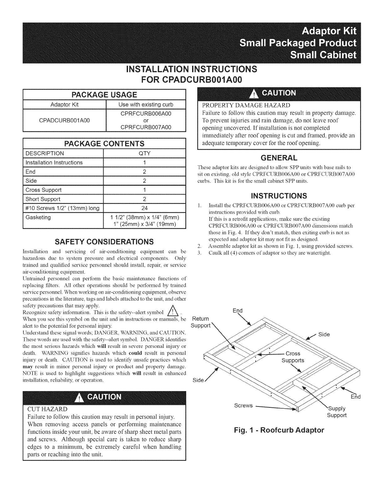
2. Assemble adaptor kit as shown in Fig. 1, using provided screws.
3. Caulk all (4) comers of adaptor so they are watertight.
Return
Support X
End
Side
CUT HAZARD
Failure to follow this caution may result in personal iniury.
When removing access panels or performing maintenance
functions inside your unit, be aware of sharp sheet metal parts
and screws. Although special care is taken to reduce sharp
edges to a minimum, be extremely careful when handling
parts or reaching into the unit.
Screws
Fig. 1 - Roofcurb Adaptor
Supply
Support
23/16"===_-
(56)
15/8"--
(41) --T
16"
(406[
303/8"J_
(772)
(254) !
R/A
OPENING
45 15/16"
(1167) _'
21(548)9/16" ------------_- _'_ (_5_)--41|
S/A
OPENING
2 3/16"
(56)
*Measurements in 0 are in mm
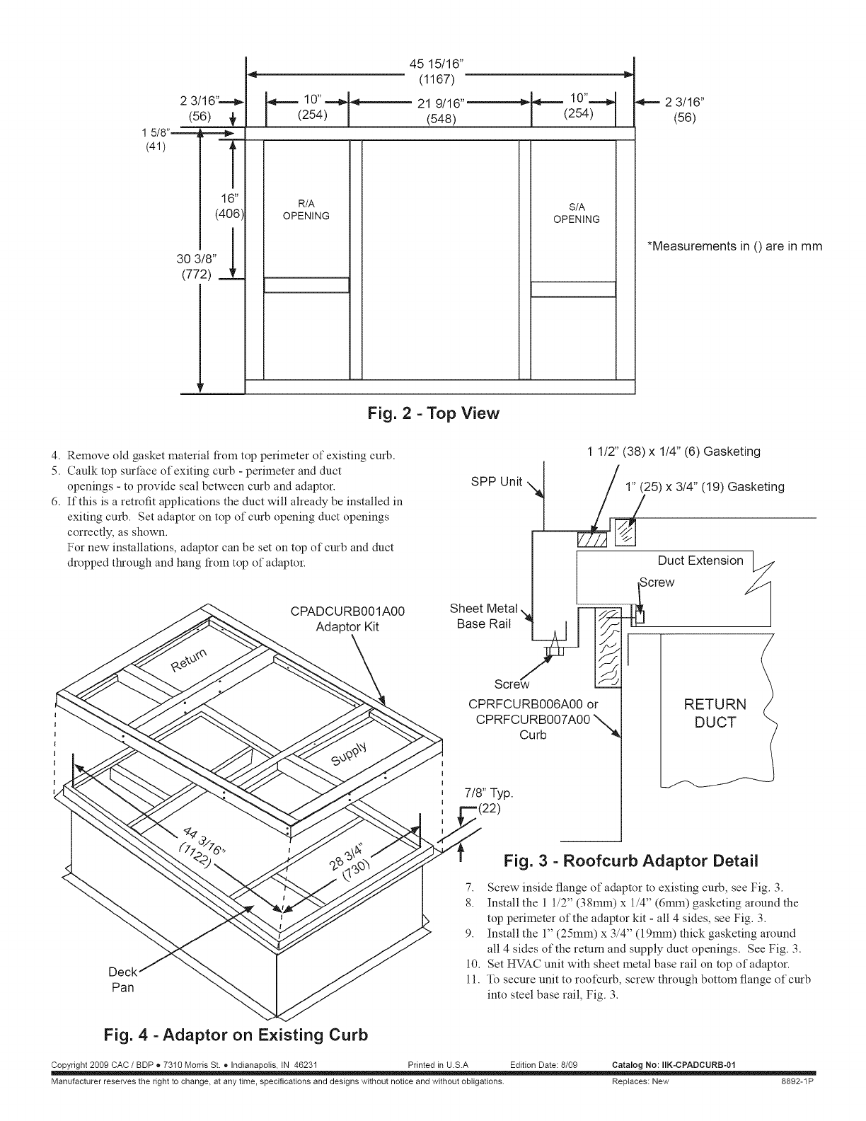
Fig. 2 - Top View
4. Remove old gasket material fiom top perimeter of existing curb.
5. Caulk top surface of exiting curb - perimeter and duct
openings - to provide seal between curb and adaptor.
6. If this is a retrofit applications the duct will already be installed in
exiting curb. Set adaptor on top of curb opening duct openings
correctly, as shown.
For new installations, adaptor can be set on top of curb and duct
dropped through and hang from top of adaptor.
CPADCURB001A00
Adaptor Kit
SPP Unit t
1 1/2" (38) x 1/4" (6) Gasketing
1" (25) x 3/4" (19) Gasketing
Sheet Metal ,_
BaseRait ' ' ] I_
Screw/
CPRFCURB006A00 or
CPRFCURB007A00
Curb
7/8" Typ.
Duct Extension_
Screw
Deck
Pan
Fig. 3- Roofcurb Adaptor Detail
7. Screw inside flange of adaptor to existing curb, see Fig. 3.
8. Install the 1 1/2" (38mm) x 1/4" (6mm) gasketing around the
top perimeter of the adaptor kit - all 4 sides, see Fig. 3.
9. Install the 1" (25mm) x 3/4" (19mm) thick gasketing around
all 4 sides of the return and supply duct openings. See Fig. 3.
10. Set HVAC unit with sheet metal base rail on top of adaptor.
11. To secure unit to roofcurb, screw through bottom flange of curb
into steel base rail, Fig. 3.
Fig. 4 -Adaptor on Existing Curb
Copyright 2009 CAC /BDP o 7310 Morris St. e Indianapolis, IN 46231 Printed in U.S.A Edition Date: 8/09 Catalog No: IIK-CPADCURB-Ol
Manufacturer reserves the right to change, at any time, specifications and designs without notice and without obligations. Replaces: New 8892-1P
