CARRIER Air Conditioner/heat Pump(outside Unit) Manual L1002284
User Manual: CARRIER CARRIER Air conditioner/heat pump(outside unit) Manual CARRIER Air conditioner/heat pump(outside unit) Owner's Manual, CARRIER Air conditioner/heat pump(outside unit) installation guides
Open the PDF directly: View PDF ![]() .
.
Page Count: 26
rll
®
to the Expertg
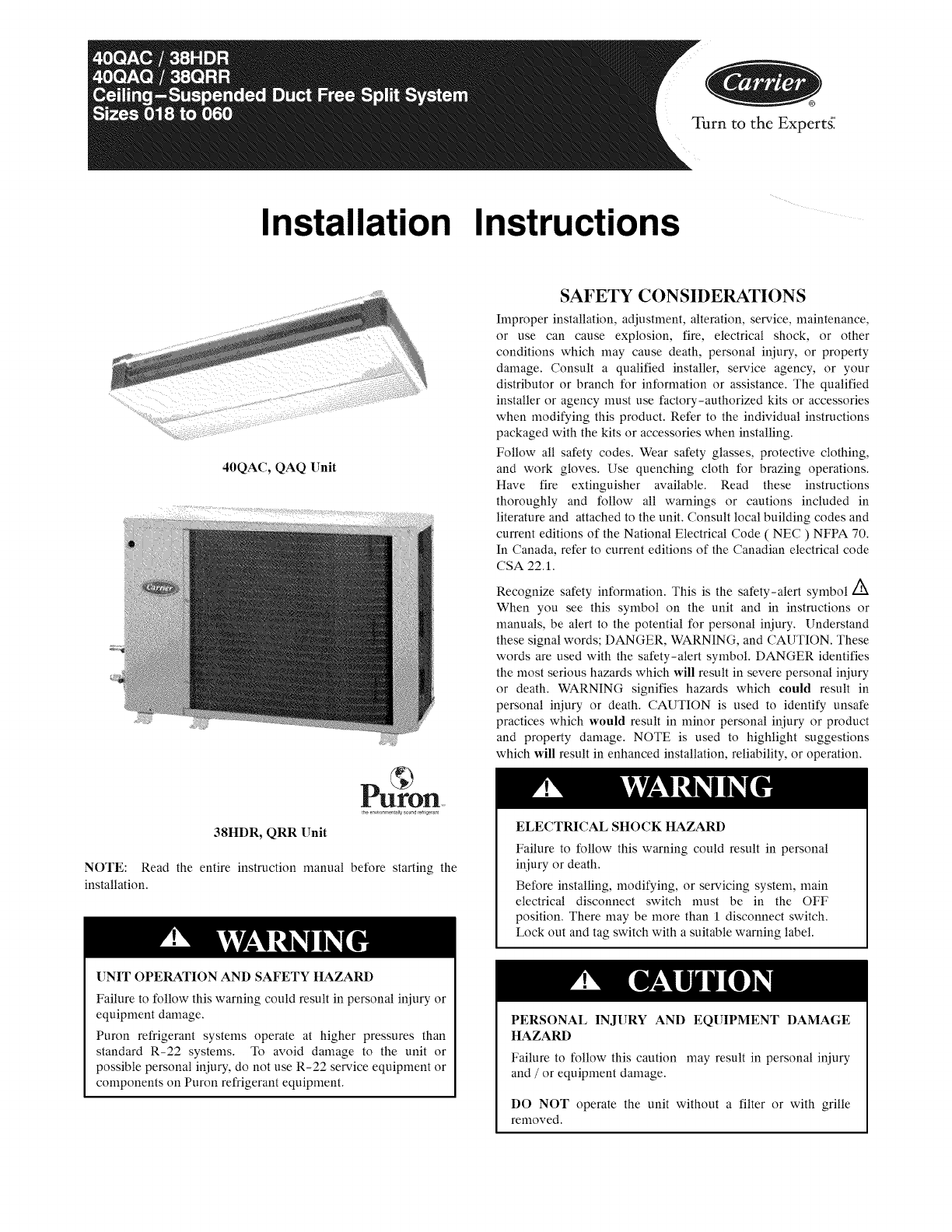
Installation Instructions
40QAC, QAQ []nit
38HDR, QRR []nit
NOTE: Read the entire instruction manual before starting the
installation.
[]NIT OPERATION AND SAFETY HAZARD
Failure to follow this warning could result in personal injury or
equipment damage.
Puron refrigerant systems operate at higher pressures than
standard R-22 systems. To avoid damage to the unit or
possible personal injury, do not use R-22 service equipment or
components on Puron refrigerant equipment.
SAFETY CONSIDERATIONS
Improper installation, adjustment, alteration, service, maintenance,
or use can cause explosion, fire, electrical shock, or other
conditions which may cause death, personal injury, or property
damage. Consult a qualified installer, service agency, or your
distributor or branch for information or assistance. The qualified
installer or agency must use factory-authorized kits or accessories
when modifying this product. Refer to the individual instructions
packaged with the kits or accessories when installing.
Follow all safety codes. Wear safety glasses, protective clothing,
and work gloves. Use quenching cloth for brazing operations.
Have fire extinguisher available. Read these instructions
thoroughly and follow all warnings or cautions included in
literature and attached to the unit. Consult local building codes and
current editions of the National Electrical Code ( NEC ) NFPA 70.
In Canada, refer to current editions of the Canadian electrical code
CSA 22.1.
Recognize safety information. This is the safety-alert symbol
When you see this symbol on the unit and in instructions or
manuals, be alert to the potential for personal injury. Understand
these signal words; DANGER, WARNING, and CAUTION. These
words are used with the safety-alert symbol. DANGER identifies
the most serious hazards which will result in severe personal injury
or death. WARNING signifies hazards which could result in
personal injury or death. CAUTION is used to identify unsafe
practices which would result in minor personal injury or product
and property damage. NOTE is used to highlight suggestions
which will result in enhanced installation, reliability, or operation.
ELECTRICALSHOCK HAZARD
Failure to follow this warning could result in personal
injury or death.
Before installing, modifying, or servicing system, main
electrical disconnect switch must be in the OFF
position. There may be more than 1 disconnect switch.
Lock out and tag switch with a suitable warning label.
PERSONAL INJURY AND EQUIPMENT DAMAGE
HAZARD
Failure to follow this caution may result in personal injury
and /or equipment damage.
DO NOT operate the unit without a filter or with grille
removed.
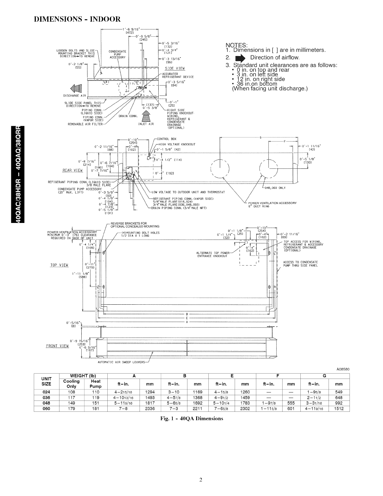
DIMENSIONS - INDOOR
NOTES:
1. Dimensions in [ ] are in millimeters.
2. _ Direction of airflow.
3. Standard unit clearances are as follows:
• 0 in. on tou and rear
• 3 in. on left side
• 12 in. on riqht side
• 36 in.on bottom
(When facing unit discharge.)
0"-10" CONTROL BOX ; G- F___]__I
[254] HIGH VOLTAGE KNOCKOUT
O" 2 11116" "-4"
[881 [102] 0'-1 5/8" [42] 1
....... I--°- -----I ..........................................................................................
[214_ I _ -%2_Y'31 II i $ 11 _ /I \ P"
[19O] ..... I I_
REAR VIEW I 0"-77/[B'_ I [t_'T_,_ [ ) { )I
--- | [ _ '4* I 0"-4" [102] \/" k_/
CONDENSATEPUNPA3[SE AoLR EY.F:A2E. UIR\\........ \ / o.8.O,ON,
(20" MAX. LIFT) 0"-3 5/8" LOW VOLTAGE TO OUTDOOR UNIT AND THERMOSTAT
_ _;:I _\\-_-_--L::F::;RANT pIp IN° CONN .(VAPOR SIDE) _, /
I]I _ _8;_?LE PLARE (018, 024) _ POWER VENTILATION ACCESSORY
0'-4 7/8" L_ 3/4"MALE FLARE(036,048,OEO)
_-_ ____ _O3/_NNpAIPING CONN, (3/4. HALE NFT) B DUCT RING
[131]
_0'-1 11116"
[42]
0"_-5 I/8"
[130]
L
POWER VENTILATION ACCESSORY
MINIMUM 0'-3 _ [763 CLEARANCE
REOUIRED IN BACK OF UNIT
V--_- {-
O' 4_/4 °
1t093
TOP VIEW o'-11L
J [2783
0"-8/16"
[8] -_7
FRONT VIEW [253]
0"-6 9/16"
[I87]
AUTOMATIC AIR SWEEP LOUVERS _
-- REVERSE BRACKETS FOR
OPT IONAL CONCEALED MOUNTING _ O' - 10_
(4)MOUNTING BOLT HOLES 0"-1 1/8" [254]
-1/2 DIA X 1 LONG 0'-1 1/4" [291 '-4"
...............................................rlO.q
ALTERNATE TOP POWER-'/ I [I72]_-,-II_I[
ENTRANCE KNOCKOU] !! L I
B
I
8
E
A
_0'-2 tl/]6"
[69]
TOP ACCESS FOR WIRING,
REFRIGERANT g ACCESSORY
CONDENSATE DRAINAGE
[OPTIONAL)
ACCESS TO CONDENSATE
PUHP THRU SIDE PANEL
WEIGHT (Ib) A
UNIT
SIZE Cooling Heat if-in, mm
Only Pump
024 108 110 4-215/16 1294
036 117 119 4-1013/16 1493
048 149 151 5-119/16 1817
060 179 181 7-8 2336
B E F
if-in, mm if-in, mm if-in, mm if-in.
3-10 1169 4-15/8 1260 -- -- 1-95/8
4--57/8 1368 4--91/2 1459 -- -- 2--11/2
5--65/8 1692 5--101/4 1783 1--97/8 555 3--31/16
7--3 2211 7--65/6 2302 1-- 115/6 601 4-- 119/16
A08580
mm
549
648
992
1512
Fig. 1 - 40QA Dimensions
UNIT SERIES
38HDRO18
38HDRO24
38NDR030
38NDR036
38HDRO48
38NDRO60
I
1.2
t
I
1,2
1,2
ELECTRICAL
CHARACTERISTICS
x0 0 0
X 0 0 0
x0 0 I 0
x o x I x
xox I x
XlOlXlX
6 '-9, 6 eb
('0 "T', (_0 ,
04 0 04 0
,_ o
V
A
L
LIL,
OPERATING
A B C D E FG H J KLMN P WEIGHTIIbsl
Z5 I18" 36 15116" 14 9116" 16" Z3 7116" 17 3116" 17 118" 22" 13" 6 518" 11 I14" 518" 215116" 6" 155
31 1/8" 36 15/16" 14 9/16" 16" 23 T/16" 17 3/16" 23 1/8" 28" 14" 6 3/4" 11 5/8" 5/8" 215116" 6" 180
37 3116" 44 9116" 17 I116" 18 7116" 30 IIZ" 19 518" 29 3/16" 34 I116" 13 11116" 8 118" t5 7/8" 314" 3 7/16" 6 I12" ZOO
37 3/16" 44 91t6" 17 1/16" 18 7/16" 30 1/2" 19 5/8" 29 3/16" 34 1/16" 13 11/16" B 1/8" t5 7/8" 314" 3 7/16" 6 1/2" 218
4_ 3/16" 44 9/161 17 1/161 18 T116" 30 I/Z I19 _181 3S _/161 40 1/161 14 I/Z I 8 I/Z I 18 7/S I 718" 3 7/16" 6 IIZ" Z8J
43 3116" 44 9116" 17 I116" 18 7/16" 30 IIZ" 19 518" 35 3/16" 40 I116" 14 IIZ" 8 I12" 18 7/8" 718" 3 7/16" 6 I12" 294
x : YES
0 : NO
E
lAIR p
I 1/2" f2 1/2"
_--'_L 4 3/16-
t '
K
lAIR J_
H'"'"''"'"'""......... FIELD CONTROL SUPPLY""-----....
WIRE ENTRY
7/8" HOLE W/GROMMET
/-_M VAPOR LINE CONN.
FEMALE SWEAT CONN.
_-_3/8" LIOUID LINE
FEMALE SWEAT CONN,
1
L
!
1
1"
re,,,_
J r
0
B.
HI
2.
3,
4,
5
JUNCTION 80X FOR
POWERSUPLLY AND
CONTROLCONNECTIONS
_t 1/2"
t
L4 I12"
SHIPPING
WEIGHTllbs)
171
198
223
240
309
SHIPPING
DIMENSIONS(L x W x H)
429110-x 18-x281/10-
42 9110" X18" X 34 1/10"
50 1/2" X 20 1/2" X 40 2/10"
50 1/2" X 20 1/2" X40 2/10"
SO 112" X20 1/2" X4G 2/10"
319 50 1/2" X 20 1/2" X46 2/10"
REOUIRED CLEARANCES: WITH COIL rACING WALL; ALLOWG" MIN
CLEARANCEON COIL SIDE AND COIL END AND 3G" MIN CLEARANCE
ON COMPRESSOREND AND FAN SIDE. WITH FAN FACING WALL; ALLOW 8" MIN
CLEARANCEON FAN SIDE AND COIL END AND 36" MIN CLEARANCE
ON COMPRESSOREND AND COIL SIDE. WITN MULTI UNIT APPLICATION;
ARRANGEUNITS SO DISCHARGE OF ONE DOES NOT ENTER INLET OF ANOTHER.
MINIMUM OUTDOOR OPERATING AMBIENT IN COOLING
MODE IS 55°F. MAX. 125°F.
SERIES DESIGNATION IS THE 13TH POSITION OF THE
UNIT MODEL NUMBER,
CENTER OF GRAVITY_
ALL DIMENSIONS ARE IN "INCHES" UNLESS NOTED.
UNITSI_ MOUNT_ PAD
D_
18,24 23" X 42"
30,36,48.60 24" X 50"
POWERSUPPLY CONN.
HOLE SIZES PROVIDED:
718"-1/?"TRADE
13/1G"-314"TRADE
1 318"-1"TRADE
17111
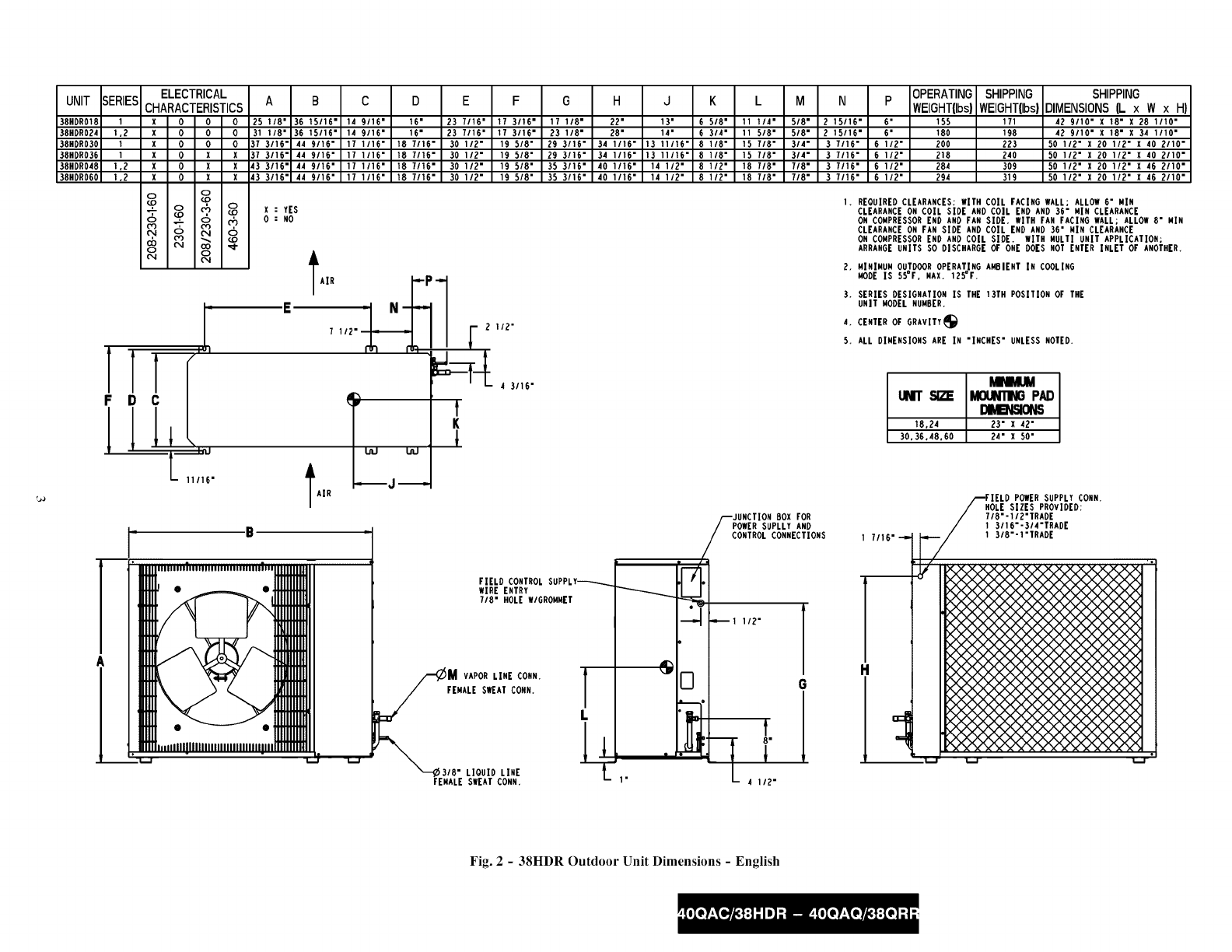
Fig. 2 -38HDR Outdoor Unit Dimensions -English
UNIT
38HDR018
38HDR024
38HDR030
38HDR036
38HDR048
38HDR060
I
1,2
I
I
1.2
1,2
I
F
I
I
A
I
EL_
CHARACll_
xOOO
xOOO
xO OIO
x o XlX
x o XlX
XlOlXIX
!!/1
t- 175
A B C D E F G H J K L M
638.2 938.2 369.9 406,4 595.3 436,6 435.0 558,8 330.2 t68,3 285,8 15,9
790.6 938,2 369,9 406.4 595.3 436.6 587.4 711.2 355.6 171,5 295.3 15,9
944,6 1t3t.9 433,4 4G8.3 774,7 498,5 741,4 865.2 347.7 20G.4 403.2 19.0
944.6 1131.9 433.4 468.3 774.7 498.5 741.4 865.2 347.7 206.4 403.2 19.0
t097.0 1t31.9 433.4 468,3 774.7 498.5 893,8 1017,G 368,3 215,9 479,4 22,2
1097,0 1131_9 433,4 468,3 774.7 498,5 893,8 1017,G 368,3 215,9 479.4 22,2
X = YES
O: NO
lAIR LL I
190,5_
t
K
1
2,
3.
4,
5,
N p 0PB_ATING_
WBQHT'_G)int0t.mKO)Dt,ABVSK3NSLxWx
74,6 t52.4 70,4 77,7 1090,2 X 457,7 X 714,3
74_G 152.4 81.8 90,0 1090.2 X 457,7 X 8GG,7
87.3 tG5.t 90.9 101.4 1282.7 X520.7 X1020,7
87.3 165.1 99.0 109.0 12B2.7x520.7x1020.7
87,3 t65.t t29,0 140,4 1282,7 X 520,7 X 1173,1
87.3 165.1 t33,6 145.0 1282,7x 520.7x 1173.1
REOUIREDCLEARAHCES: WITH COIL FACIHG WALL; ALLOW152,4 XIH
CLEARANCEON COIL SIDE AND COIL END AND 914,4 MIN CLEARANCE
OH GOMPRESSOREHD AND FAH SIDE, WITH FAN FACING WALL; ALLOW203.2 MIN
CLEARANCEON FAN SIDE AND COIL END AND 914,4 MIN CLEARANCE
ON COMPRESSOREHD AND COIL SIDE. WITH MULTI UNIT APPLICATION;
ARRANGEUNITS SO DISCHARGEOF ONE DOES NOT ENTER INLET OF ANOTHER,
MINIMUM OUTDOOROPERATING AMBIENT [H COOLING
MODE IS 12._C. MAX. 51.?C.
SERIES DESIGNATION IS THE 13TH POSITION OF THE
UNIT MODELNUMBER,
CENTEROF GRAVITY_
ALL DIMEHSIONS ARE IN "MM" UNLESS NOTED.
uNrr sizz MOUNTINGPAD
18.24 584.2 X t066.8
30,36.48,60 609,6 X1270,0
B
• '"'"'".................... 'FIELD CONTROLSUPPLY_
WIRE ENTRY
22.22 HOLE W/GROMMET
JUNCTION BOX FOR
POWERSUPLLY AND
CONTROLCONNECTIONS
,I f
D
"L
r
38,1
_M VAPORLINE CONN. ]
FEMALE SWEATCONN. GI/
l
FEMALESWEATCONN.
H
1
36.5-"
FIELD POWERSUPPLYCONN.
HOLE SIZES PROVIDED:
22.22 -12.70 TRADE
30,16 -19,05 TRADE
34.92 -25.40 TRADE
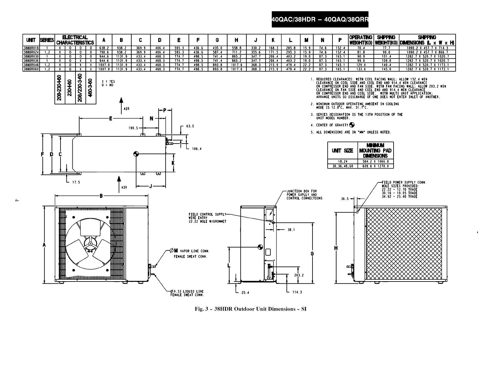
Fig. 3 -38HDR Outdoor Unit Dimensions -SI
UNIT 5B_IES
38QRR018
38QRRO24
38QRR030
38QRRO36
38QRR048
380RR060
0
0
0
0
0
0
T
F
I
E_C_CAL
CHARACT_S_CS
x 0 0 0
XlOlOlO
X0010
X0xlx
X 0 XlX
Xl°lXIN
A B C D E F G H JK L M N P
25 1/8" 36 t5/t6" 14 9/16" t6" 23 7/16" 17 3/16" t7 1/8" 22" 13" 6 5/8" 1t 1/4" 5/8" 2 15!16" 6"
31 I18" 36 15116" 14 9116" 16" 23 7116" 17 3116" 23 I18" 28" 14" 6 314" 11 518" 518" 2 15116" 6"
37 3116" 44 9116" 17 1116" 18 7116" 30 112" 19 518" 29 3116" 34 1116" 13 11116" 8 118" 15 718" 314" 3 7116" 6 112"
37 3116" 44 9116" 17 1116" 18 7116" 30 112" 19 518" 29 3116" 34 1116" 13 11116" 8 118" 15 718" 314" 3 7116" 6 112"
43 3116" 44 9116" 17 1116" 18 7116" 30 112" 19 518" 35 3116" 40 1116" 14 112" 8 112" 18 718" 718" 3 7116" 6 112"
43 3116" 44 9116" 17 1116" 18 7116" 30 112" 19 518" 35 3116" 40 1116" 14 112" 8 112" 18 718" 718" 3 7116" 6 112"
IAIR
I
IAIR
f
K
l
VAPOR LINE CONN,
FEMALE SWEAT CONN,
LIOUID LINE
MALE FLARE CONN.
FIELD CONTROL SUPPLY_---_
WIRE ENTRY
718" HOLE WIGROMMET
I
L
oF-i
[]
2.
3,
4,
5.
JUNCTION BOX FOR
POWER SUPLLY AND
CONTROL CONNECTIONS
_t 1/2"
G
,1
8"
X : YES
0:NO
OPB_ATING SHIPPING SHIPPING
WBGHTabs)WBGHTllbs)DIMB_ISIONS(L x WxHI
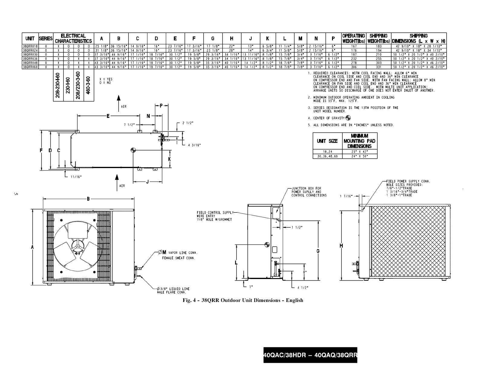
167 183 429110.x_o,,x 28ino"
176 194 42 9/10" X 18" X 34 1/10"
187 210 50 1/2" X 20 1/2" X 40 2/10"
232 255 50 1/2" X 20 1/2" X 40 2/10"
278 303 50 t/2" X 20 t/2" X 46 2!10"
306 331 50 112" X 20 112" X 46 2110"
REOUIRED CLEARANCES: WITH COIL FACING WALL; ALLOW 6" MIN
CLEARANCE ON COIL SIDE AND COIL END AND 36" MIN CLEARANCE
ON COMPRESSOR END AND FAN SIDE. WITH FAN FACING WALL; ALLOW 8" MIN
CLEARANCE ON FAN SIDE AND COIL END AND 36" MIN CLEARANCE
ON COMPRESSOR END AND COIL SIDE. WITH MULTI UNIT APPLICATION;
ARRANGE UNITS SO DISCHARGE OF ONE DOES NOT ENTER INLET OF ANOTHER.
MINIMUM OUTDOOR OPERATING AMBIENT IN COOLING
MODE IS 55°F, MAX. 125°F.
SERIES DESIGNATION IS THE 13TH POSITION OF THE
UNIT MODEL NUMBER,
CENTER OF GRAVITY_
ALL DIMENSIONS ARE IN "INCHES" UNLESS NOTED.
_IhlIVlUM
UMT SITW MOUNTINGPAD
DIMB_ISIONS
18,24 23" X 42"
30,36,48,60 24" X 50"
POWER SUPPLY CONN,
HOLE SIZES PROVIDED:
718"-II2"TRADE
1 3116"-314"TRADE
1 318"-I"TRADE
Fig. 4 -38QRR Outdoor Unit Dimensions -English
UMT SB:IIES BCDE FGHJK L M
380RR018 0 638.2 938.2 369.9 406.4 595.3 436.6 435.0 558.8 330.2 168.3 285.8
380RR024 0 790.6 938.2 369.9 406.4 595.3 436.6 587.4 711.2 355.6 171.5 295.3
380RR030 0 944.6 1131,9 433,4 468.3 774,7 498,5 741.4 865.2 347,7 206,4 403.2 1282.7 X 520.7 X 1020,7
380RR036 0 944.6 1131.9 433.4 468.3 7?4.7 498.5 741.4 865.2 347.7 206.4 403.2 1282.7 X 520.7 X 1020.7
380RH048 0 1097,0 1131.9 433,4 468.3 774.7 498,5 893.8 1017.6 368.3 215,9 479.4 1282,7 X 520.7 X 1173,1
380RR060 0 1097.0 1131.9 433.4 468.3 774.7 498.5 893.8 1017,6 368,3 215.9 479.4 1282.7 X 520.7 X 1173.1
B.ECTRICAL
CHARAC'I'B_ISTICS
x 0 0 0
x 0 0 0
x 0 0 I0
x 0 x I x
x 0 x I x
XlOlXlX
o 8
X:YES
0:NO
!!r'll
IAIR J uu'
F
I
-B
OPERATING
N P WBOHT(KO)
15.9 74.6 152.4 75.9
15.9 74.6 t52.4 80.0
19.0 87.3 165.1 85.0
19.0 87.3 165.1 105,4
22.2 87.3 t65.1 126.4
22.2 87.3 165.1 139.0
I.
I 2.
E4.
190,5 F 63.5 5,
SI-IPRNG
WBGHT(KO)
83.2
88.2
95,4
115.9
137.7
150,4
SHIPPING
DIMB_51ONG(L xWxH)
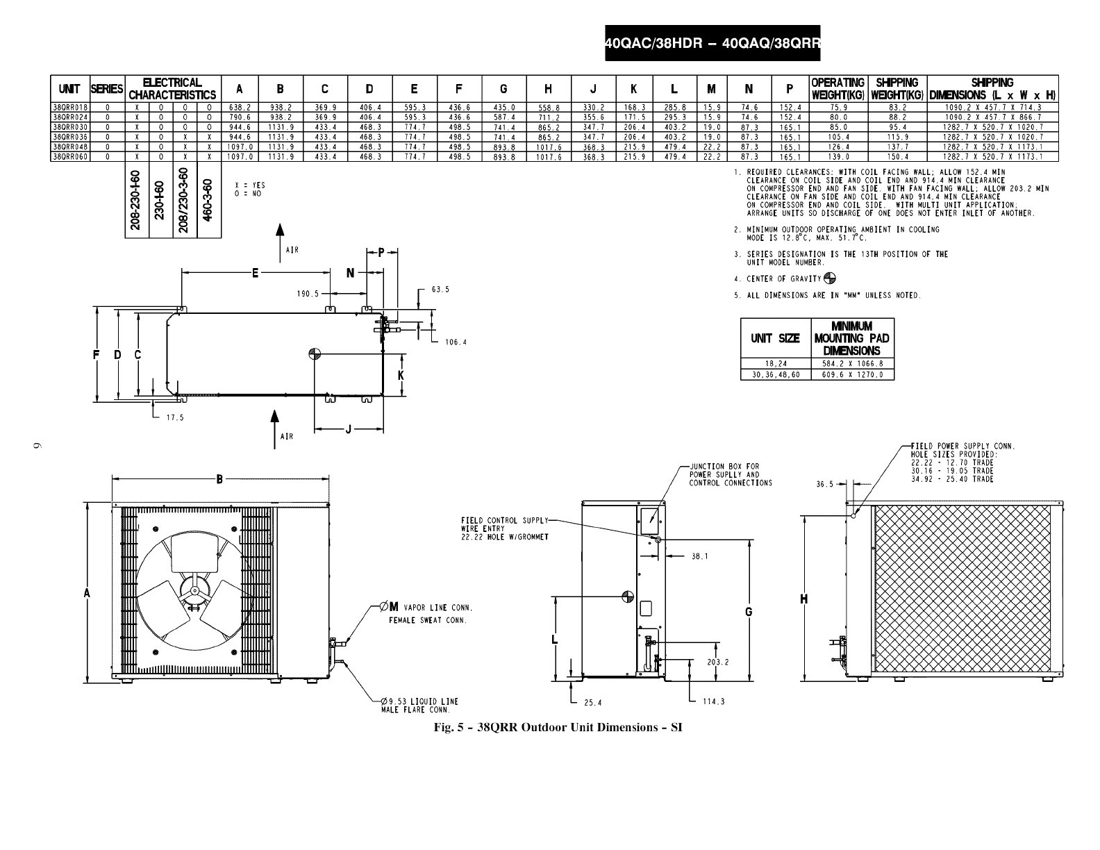
1090.2 X 457.7 X 714.3
1090.2 X 457.7 X 866.7
REOUIRED CLEARANCES: WITH COIL FACING WALL; ALLOW152,4 MIN
CLEARANCE ON COIL SIDE AND COIL END AND 914.4 MIN CLEARANCE
ON COMPRESSOR END AND FAN SIDE, WITH FAN FACING WALL; ALLOW 203,2 MIN
CLEARANCE ON FAN SIDE AND COIL END AND 914.4 MIN CLEARANCE
ON COMPRESSOR END AND COIL SIDE. WITH MULTI UNIT APPLICATION;
ARRANGE UNITS SO DISCHARGE OF ONE DOES NOT ENTER INLET OF ANOTHER.
t
K
MINIMUM OUTDOOROPERATING AMBIENT IN COOLING
MODE IS 12.8°C, MAX. 51.7°C.
106.4
FIELD CONTROL SUPPLY_------_
WIRE ENTRY
22.22 HOLE WlGROMMET
VAPOR LINE CONN.
FEMALE SWEAT CONN,
LIOUIDLINE
MALE FLARE CONN.
T
L
o
.I/
o
@[]
r
° _.L._u
JUNCTION BOX FOR
POWER SUPLLY AND
CONTROL CONNECTIONS
38.1
G
t
SERIES DESIGNATION IS THE 13TH POSITION OF THE
UNIT MODEL NUMBER.
CENTER OF GRAVITY_
ALL DIMENSIONS ARE IN "MM" UNLESS NOTED.
MINIMUM
UNIT SI2_ MOUNTINGPAD
DIIVlB_51ONS
18,24 584,2 X 1066.8
30.36,48,60 609,6 X 1270.0
36.5 _
FFIELD POWER SUPPLY CORN,
/HOLE SIZES PROVIDED:
/22,22 - 12.70 TRADE
/30.16 -19.05 TRADE
_/34.92-25.40TRADE
25,4
q 203.2
1
114.3
Fig. 5 -38QRR Outdoor Unit Dimensions -SI
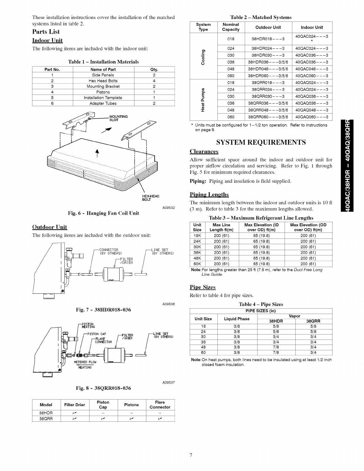
These installation instructions cover the installation of the matched
systems listed in table 2.
Parts List
Indoor Unit
The following items are included with the indoor unit:
Table I -Installation Materials
Part No. Name of Part Qty.
1 Side Panels 2
2 Hex Head Bolts 4
3 Mounting Bracket 2
4 Pistons 1
5 Installation Template 1
6 Adapter Tubes 2
MOUNTING
SLOT
HEX-HEAD
BOLT
Fig. 6 - Hanging Fan Coil Unit
Outdoor Unit
The following items are included with the outdoor unit:
A09532
u-FILTER /
Fig. 7 -38HDR018-036
A09536
_F PISTON
HEATING
PISTON CAP FILTER _._LINE SET
__ET_ERE_I_/--FLARE /--/DRIER !(BY OTHERS)
HEATING
Fig. 8 -38QRR018-036
A09537
Piston Flare
Model Filter Drier Pistons
Cap Connector
38HDR _" - - -
38QRR w- w- w- w-
Table 2 - Matched Systems
System Nominal
Type Capacity Outdoor Unit Indoor Unit
40QACO24- - -3
018 38HDRO18---3 .
024 38HDR024---3 40QAC024---3
==
"- 030 38HDR030---3 40QAC036---3
"5
o
O 036 38HDR036---3/5/6 40QAC036---3
048 38HDRO48- - -3/5/6 40QACO48- - -3
060 38HDRO60- - -3/5/6 4OQACO6O- - -3
018 38QRRO18---3 40QAQO24---3
_. 024 38QRRO24- - -3 40QAQO24- - -3
_= 030 38QRRO30---3 40QAQO36---3
iD.
036 38QRRO36- - -3/5/6 40QAQO36- - -3
:'r 048 38QRRO48- - -3/5/6 40QAQO48- - -3
060 38QRRO60- - -3/5/6 4OQAQO6O- - -3
Units must be configured for 1-1/2 ton operation. Refer to instructions
on page 9.
SYSTEM REQUIREMENTS
Clearances
Allow sufficient space around the indoor and outdoor unit for
proper airflow circulation and servicing. Refer to Fig. 1 through
Fig. 5 for minimum required clearances,
Piping: Piping and insulation is field supplied,
PiDin_ Lengths
The minimum length between the indoor and outdoor units is 10 fl
(3 m). Refer to table 3 for the maximum lengths allowed.
Table 3 -Maximum Refrigerant Line Lengths
Unit Max Line Max Elevation (ID Max Elevation (OD
Size Length if(m) over OD) if(m) over OD) if(m)
18K 200 (61) 65 (19.8) 200 (61)
24K 200 (61) 65 (19.8) 200 (61)
3OK 200 (61) 65 (19.8) 200 (61)
36K 200 (61) 65 (19.8) 200 (61)
48K 200 (61) 65 (19.8) 200 (61)
6OK 200 (61) 65 (19.8) 200 (61)
Note:For lengths greater than 25 ft (7.6 m), refer to the Duct Free Long
Line Guide.
Pipe Sizes
Refer to table 4 for pipe sizes.
Table 4 - Pipe Sizes
PIPE SIZES (in)
Unit Size
18
24
30
36
48
60
Liquid Phase
3/8
3/8
3/8
3/8
3/8
3/8
Vapor
38HDR 38QRR
5/8 5/8
5/8 5/8
3/4 3/4
3/4 3/4
7/8 3/4
7/8 3/4
Note:On heat pumps, both lines need to be insulated using at least 1/2 inch
closed foam insulation.
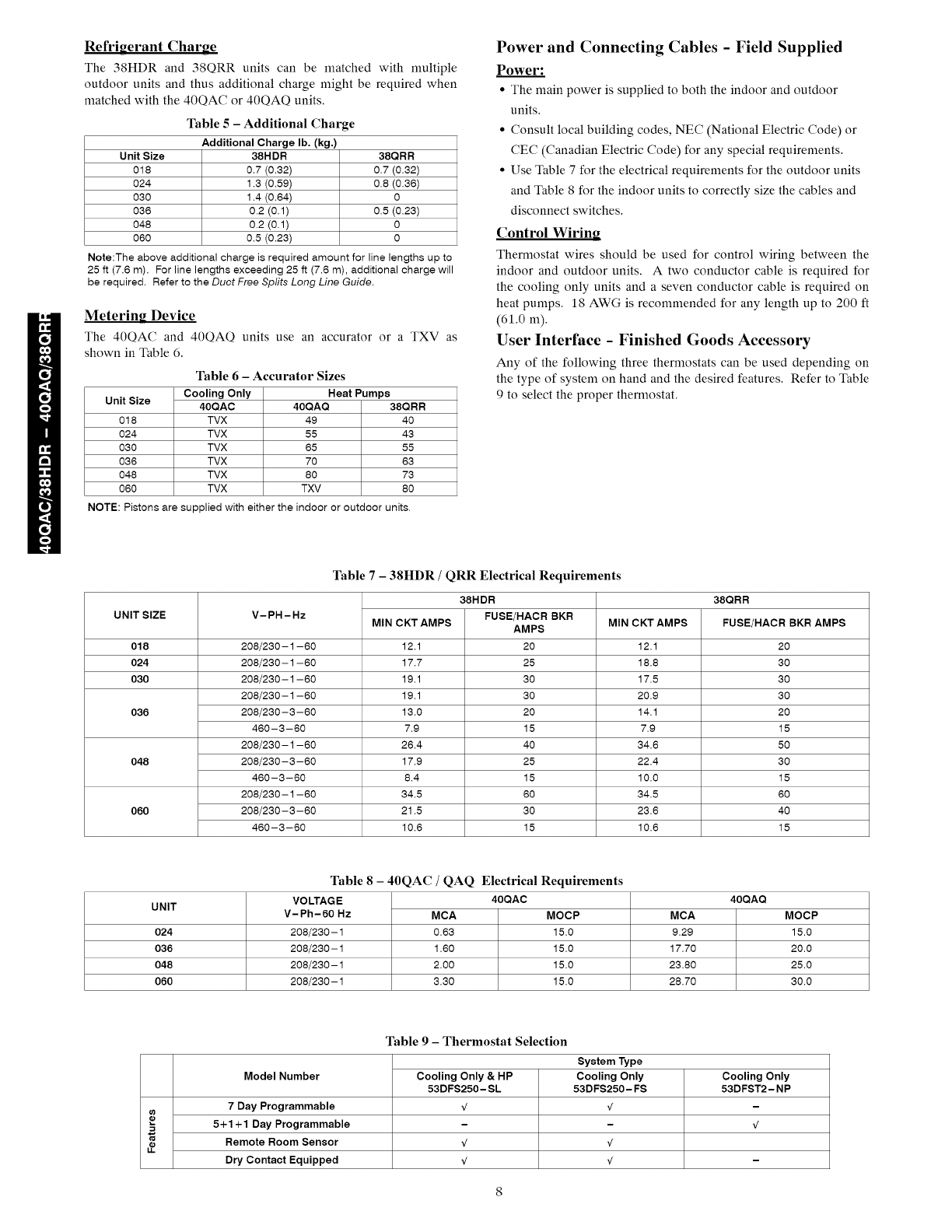
Refriuerant Charge
The 38HDR and 38QRR units can be matched with multiple
outdoor units and thus additional charge might be required when
matched with the 40QAC or 40QAQ units.
Table 5-Additional Charge
Additional Charge lb. (kg.)
Unit Size 38HDR 38QRR
018 0.7 (0.32) 0.7 (0.32)
024 1.3 (0.59) 0.8 (0.36)
030 1.4 (0.64) 0
036 0.2 (0.1) 0.5 (0.23)
048 0.2 (0.1) 0
060 0.5 (0.23) 0
Note:The above additional charge is required amount for line lengths up to
25 ft (7.6 m). For line lengths exceeding 25 ft (7.6 m), additional charge will
be required. Refer to the Duct Free Splits Long Line Guide.
Metering Device
The 40QAC and 40QAQ units use an accurator or a TXV as
shown in Table 6.
Table 6- Accurator Sizes
Unit Size Cooling Only Heat Pumps
40QAC 40QAQ 38QRR
018 TVX 49 40
024 TVX 55 43
030 TVX 65 55
036 TVX 70 63
048 TVX 80 73
060 TVX TXV 80
NOTE: Pistons are supplied with either the indoor or outdoor units.
Power and Connecting Cables -Field Supplied
Power:
• The main power is supplied to both the indoor and outdoor
units.
• Consult local building codes, NEC (National Electric Code) or
CEC (Canadian Electric Code) for any special requirements.
• Use Table 7 for the electrical requirements for the outdoor units
and Table 8 for the indoor units to correctly size the cables and
disconnect switches.
Control Wiring
Thermostat wires should be used for control wiring between the
indoor and outdoor units. A two conductor cable is required for
the cooling only units and a seven conductor cable is required on
heat pumps, 18 AWG is recommended for any length up to 200 ft
(61.0 m).
User Interface - Finished Goods Accessory
Any of the following three thermostats can be used depending on
the type of system on hand and the desired features. Refer to Table
9to select the proper thermostat.
UNIT SIZE V-PH-Hz
Table 7-38HDR /QRR Electrical Requirements
38HDR
FUSE/HACR BKR
MIN CKT AMPS MIN CKT AMPS
AMPS
20
25
30
30
20
15
40
25
15
60
30
15
018 208/230-1-60 12.1 12.1
024 208/230-1-60 17.7 18.8
030 208/230-1-60 19.1 17.5
208/230-1-60 19.1 20.9
036 208/230 -3 -60 13.0 14.1
460-3 -60 7.9 7.9
208/230-1-60 26.4 34.6
048 208/230-3 -60 17.9 22.4
460-3 -60 8.4 10.0
208/230-1-60 34.5 34.5
060 208/230 -3 -60 21.5 23.6
460-3-60 10.6 10.6
40QAQ
38QRR
FUSE/HACR BKR AMPS
20
30
30
30
20
15
50
30
15
60
40
15
UNIT MCA MOCP
024 9.29 15.0
036 17.70 20.0
048 23.80 25.0
060 28.70 30.0
Table 9 - Thermostat Selection
Table 8 -40QAC /QAQ Electrical Requirements
VOLTAGE 40QAC
V-Ph-60 Hz MCA MOCP
208/230-1 0.63 15.0
208/230-1 1.60 15.0
208/230-1 2.00 15.0
208/230-1 3.30 15.0
Model Number
System Type
Cooling Only
53DFS250-FS
Cooling Only & HP
53DFS250-SL
7 Day Programmable
5+1 +1 Day Programmable
=
Remote Room Sensor _/
#_
Dry Contact Equipped _/ -
Cooling Only
53DFST2-NP
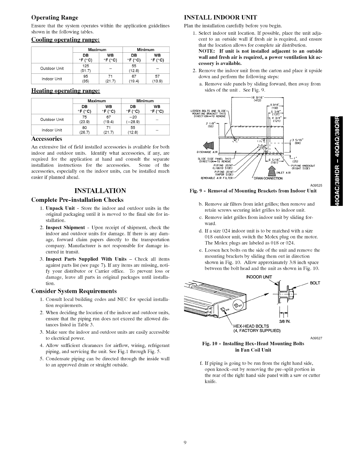
Operating Range
Ensure that the system operates within the application guidelines
shown in the following tables.
Cooling operating range:
Maximum
DB WB
°F (°C) °F (°C)
128
Outdoor Unit - -
(51.7)
95 71 57
Indoor Unit (35) (21.7) (13.9)
Heating operating range:
Outdoor Unit
Indoor Unit
Accessories
Maximum
DB WB
°F (°C) °F (°C)
75 67
(23.9) (19.4)
80 71
(26.7) (21.7)
Minimum
DB WB
°F (°C) °F (°C)
55
(12.8)
67
(19.4)
Minimum
DB WB
°F (°C) °F (°C)
-20
(-28.9)
55
(12.8)
An extensive list of field installed accessories is available for both
indoor and outdoor units. Identify what accessories, if any, are
required for the application at hand and consult the separate
installation instructions for the accessories. Some of the
accessories, especially on the indoor units, can be installed much
easier if planned ahead.
INSTALLATION
Complete Pro-installation Checks
1. Unpack Unit - Store the indoor and outdoor units in the
original packaging until it is moved to the final site for in-
stallation.
2. Inspect Shipment - Upon receipt of shipment, check the
indoor and outdoor units for damage. If there is any dana-
age, forward claim papers directly to the transportation
company. Manufacturer is not responsible for damage in-
curred in transit.
3. Inspect Parts Supplied With Units - Check all items
against parts list (see page 7). If any items are missing, noti-
fy your distributor or Carrier office. To prevent loss or
damage, leave all parts in original packages until installa-
tion.
Consider System Requirements
1. Consult local building codes and NEC for special installa-
tion requirements.
2. When deciding the location of the indoor and outdoor units,
ensure that the piping run does not exceed the allowed dis-
tances listed in Table 3.
3. Make sure the indoor and outdoor units are easily accessible
to electrical power.
4. Allow sufficient clearances for airflow, wiring, refrigerant
piping, and servicing the unit. See Fig.l through Fig. 5.
5. Condensate piping can be directed through the inside wall
to an approved drain or straight outside.
INSTALL INDOOR UNIT
Plan the installation carefully before you begin.
1. Select indoor unit location. If possible, place the unit adja-
cent to an outside wall if fresh air is required, and ensure
that the location allows for complete air distribution.
NOTE: If unit is not installed adjacent to an outside
wall and fresh air is required, a power ventilation kit ac-
cessory is available.
2. Remove the indoor unit from the carton and place it upside
down and perform the following steps:
a. Remove side panels by sliding forward, then away from
sides of the unit. See Fig. 9.
[4721
;3/16"
LOOSEN BOLTS AND SLIDE- "_3Js"_J
HOUNTIBG BRACKET THIS )[3_8
OIRECIION_TO RENOVE 4_2_i. _4314"
2I/8 ,4
'L'OE 'BE ,,ELT.',J //i/ F, ,,,B. --L,.
BIRECTION_TO REHOVE i _ [!611_ [253
/:\.,.,...oo<o.,
(LIQUID SIDE) /N,.E ,B,0...,BE,
_WPOBSIBE_//
R,EMOVABLE AIR FILTER _ _DRAINCONNECTION
A09525
Fig. 9-Removal of Mounting Brackets from Indoor Unit
b. Remove air filters from inlet grilles; then remove and
retain screws securing inlet grilles to indoor unit.
c. Remove inlet grilles from indoor unit by sliding for-
ward.
d. If a size 024 indoor unit is to be matched with a size
018 outdoor unit, switch the Molex plug on the motor.
The Molex plugs are labeled as 018 or 024.
e. Loosen hex bolts on the side of the unit and remove the
mounting brackets by sliding them out in direction
shown in Fig. 10. Allow approximately 3/8 inch space
between the bolt head and the unit as shown in Fig. 10.
INDOORUNIT
BO,T
_EAD BOLTS 3/8 IN.
(4, FACTORY SUPPLIED)
A09527
Fig. 10 - Installing Hex-Head Mounting Bolts
in Fan Coil Unit
f. If piping is going to be run from the right hand side,
open knock-out by removing the pre-split portion in
the rear of the right hand side panel with a saw or cutter
knife.
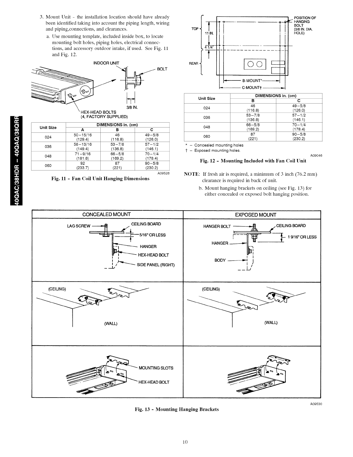
3.MountUnit- the installation location should have already
been identified taking into account the piping length, wiring
and piping,connections, and clearances.
a. Use mounting template, included inside box, to locate
mounting bolt holes, piping holes, electrical connec-
tions, and accessory outdoor intake, if used. See Fig. 11
and Fig. 12.
INDOORUNIT
_,._ BOLT
_EAD BOLTS 3/8 IN.
(4, FACTORY SUPPLIED)
Unit Size
O24
O36
O48
O6O
A
50-15/16
(129.4)
58-13/16
(149.4)
71-9/16
(181.8)
92
(233.7)
DIMENSIONS in. (cm)
B
46
(116.8)
53 -7/8
(136.8)
66-5/8
(169.2)
87
(221)
c
49-5/8
(126.0)
57-1/2
(146.1)
70-1/4
(178.4)
90-5/8
(230.2)
A09528
Fig. 11 - Fan Coil Unit Hanging Dimensions
TOP -
REAR,
,_ 4 1/4+ "®'-'(
B-MOUNT*
3-MOUNT1"
POSITION OF
--_"HANGING
BOLT
(3]8 IN. DIA.
HOLE)
Unit Size
O24
O36
O48
O6O
- Concealed mounting holes
- Exposed mounting holes.
DIMENSIONS in. (cm)
B C
46 49-5/8
(116.8) (126.0)
56 - 7/8 57-1/2
(136.8) (146.1)
66- 5/8 70-1/4
(169.2) (178.4)
87 90-5/8
(221) (230.2)
Fig. 12 - Mounting Included with Fan Coil Unit
A09046
NOTE: If fresh air is required, a n_ininmm of 3 inch (76.2 ram)
clearance is required in back of unit.
b. Mount hanging brackets on ceiling (see Fig. 13) for
either concealed or exposed bolt hanging position.
(CEILING)
CONCEALED MOUNT EXPOSED MOUNT
LAGSCREW _ ,_f CEILINGBOARD
___5/16" OR LESS
I I
I/_"'-_. SIDEPANEL(RIGHT)
__.1_
(WALL)
-:ADBOLT
HANGERBOLT _ _ CEILINGBOARD
HANGER_-_f
i I
BODY _ j
I
I/
(CEIUNG)
(WALL)
A09530
Fig. 13 - Mounting Hanging Brackets
10
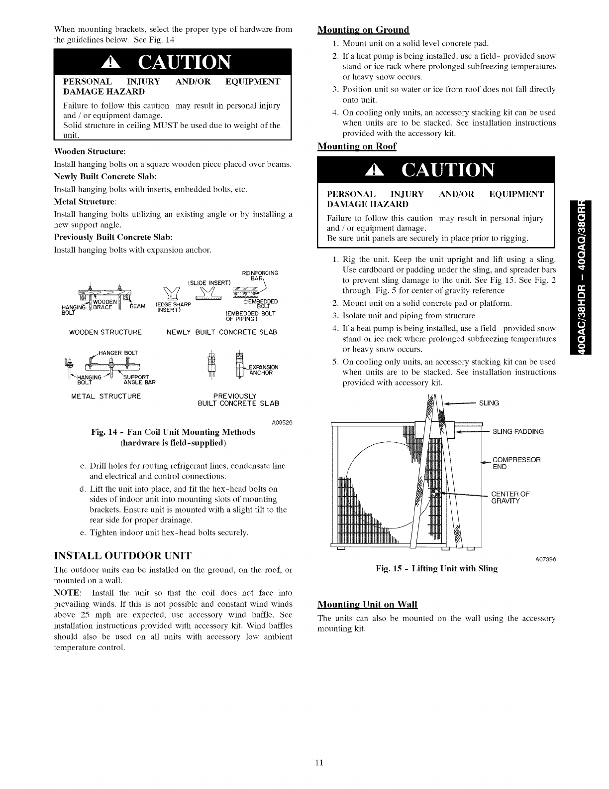
Whenmountingbrackets,selectthepropertypeofhardwarefrom
theguidelinesbelow.SeeFig.14
PERSONALINJURY AND/OR EQUIPMENT
DAMAGEHAZARD
Failureto follow this caution may result in personal injury
and /or equipment damage.
Solid structure in ceiling MUST be used due to weight of the
unit.
Wooden Structure:
Install hanging bolts on a square wooden piece placed over beams.
Newly Built Concrete Slab:
Install hanging bolts with inserts, embedded bolts, etc.
Metal Structure:
Install hanging bolts utilizing an existing angle or by installing a
new support angle.
Previously Built Concrete Slab:
Install hanging bolts with expansion anchor.
REINFORCING
(SLIDE INSERT) BAR_
_EDDED
!I OODENil BEAM BO T
(EDGE SHARP
HANGING jlt BRACE INSERT)
BOLT (EMBEDDED BOLT
OF PIPING )
WOODEN STRUCTURE NEWLY BUILT CONCRETE SLAB
RANG, ORT ANC.OR
BOLT ANGLE BAR
METAL STRUCTURE PREVIOUSLY
BUILT CONCRETESLAB
Fig. 14 - Fan Coil Unit Mounting Methods
(hardware is field-supplied)
A09526
c. Drill holes for routing refrigerant lines, condensate line
and electrical and control connections.
d. Lift the unit into place, and fit the hex-head bolts on
sides of indoor unit into mounting slots of mounting
brackets. Ensure unit is mounted with a slight tilt to the
rear side for proper drainage.
e. Tighten indoor unit hex-head bolts securely.
INSTALL OUTDOOR UNIT
The outdoor units can be installed on the ground, on the roof, or
mounted on a wall.
NOTE: Install the unit so that the coil does not face into
prevailing winds. If this is not possible and constant wind winds
above 25 mph are expected, use accessory wind baffle. See
installation instructions provided with accessory kit. Wind baffles
should also be used on all units with accessory low ambient
temperature control.
Mounting on Ground
1. Mount unit on a solid level concrete pad.
2. If a heat pump is being installed, use a field- provided snow
stand or ice rack where prolonged subfreezing temperatures
or heavy snow occurs.
3. Position unit so water or ice from roof does not fall directly
onto unit.
4. On cooling only units, an accessory stacking kit can be used
when units are to be stacked. See installation instructions
provided with the accessory kit.
Mounting on Roof
PERSONAL INJURY AND/OR EQUIPMENT
DAMAGE HAZARD
Failure to follow this caution may result in personal injury
and /or equipment damage.
Be sure unit panels are securely in place prior to rigging.
1. Rig the unit. Keep the unit upright and lift using a sling.
Use cardboard or padding under the sling, and spreader bars
to prevent sling damage to the unit. See Fig 15. See Fig. 2
through Fig. 5 for center of gravity reference
2. Mount unit on a solid concrete pad or platform.
3. Isolate unit and piping from structure
4. If a heat pump is being installed, use a field- provided snow
stand or ice rack where prolonged subfreezing temperatures
or heavy snow occurs.
5. On cooling only units, an accessory stacking kit can be used
when units are to be stacked. See installation instructions
provided with accessory kit.
SUNG
SUNG PADDING
COMPRESSOR
END
CENTER OF
GRAVFY
Fig. 15 - Lifting []nit with Sling
A07396
Mounting Unit on Wall
The units can also be mounted on the wall using the accessory
mounting kit.
11
Complete Outdoor Refrigerant Piping Connec-
tions
Follow the following general guidelines:
1. Use refrigerant grade field - supplied tubing.
Refer to Table 4 for the correct line sizes.
2. Do not use less than 10 ft (93.05 m) of interconnecting
tubing.
[]NIT DAMAGE HAZARD
Failure to follow this caution may result in equipment
damage or improper operation.
If any section of pipe is buried, there nmst be a 6 in. (152.4
ram) vertical rise to the valve connections on the outdoor
unit. If more than the recommended length is buried,
refrigerant may nfigrate to cooler, buried section during
extended periods of system shutdown. This causes
refrigerant slugging and could possibly damage the
compressor at start-up.
When more than 80 fl (24.4 m) of interconnecting tubing is used,
consult the Duct-Free Split System Long Line Application Guide
for required accessories.
3. On cooling only units, insulate the liquid line. On heat
pumps, insulate both lines. A minimum of 1/2 inch foam
pipe insulation is recommended.
4. Run the refrigerant tubes as directly as possible and avoid
unnecessary turns and bends.
5. Suspend refrigerant tubes to avoid damage to insulation or
tubes so they do not transnfit vibration to the structure.
6. When passing refrigerant tubes through the wall, seal the
opening so rain and insects do not enter the structure. Leave
some slack in refrigerant tubes between structure and out-
door unit to absorb vibration.
NOTE: A fusible plug is located in unit suction line; do not cap
this plug. If local codes require additional safety devices, install as
directed.
Connection at Outdoor Unit
[]NIT DAMAGE HAZARD
Failure to follow this caution may result in equipment damage
or improper operation.
To prevent damage to unit or service valves observe the
following:
• A brazing shield MUST be used.
• Wrap service valves with wet cloth or use a heat sink
material.
1. Braze the connector tubes (field supplied for the 38HDR
units and factory supplied for the 38QRR units) to the inlet
of the factory supplied filter drier. If a cooling only unit is
being installed move to step 3 (see Fig. 8).
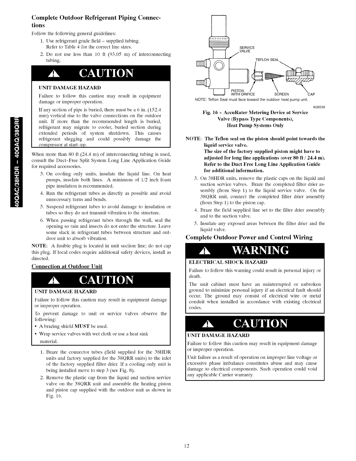
2. Remove the plastic cap from the liquid and suction service
valve on the 38QRR unit and assemble the heating piston
and piston cap supplied with the outdoor unit as shown in
Fig. 16.
I 1 SERVICE
VALVE
1]_ TEFLON SEAL
NOTE:TeflonSeal mustface toward the outdoor heat pumpunit.
A09538
Fig. 16 -AccuRater Metering Device at Service
Valve (Bypass Type Components),
Heat Pump Systems Only
NOTE: The Teflon seal on the piston should point towards the
liquid service valve.
The size of the factory supplied piston might have to
adjusted for long line applications (over 80 ft /24.4 m).
Refer to the Duct Free Long Line Application Guide
for additional information.
3. On 38HDR units, remove the plastic caps on the liquid and
suction service valves. Braze the completed filter drier as-
sembly (from Step 1) to the liquid service valve. On the
38QRR unit, connect the completed filter drier assembly
(from Step 1) to the piston cap.
4. Braze the field supplied line set to the filter drier assembly
and to the suction valve.
5. Insulate any exposed areas between the filter drier and the
liquid valve.
Complete Outdoor Power and Control Wiring
ELECTRICAL SHOCK HAZARD
Failure to follow this warning could result in personal iniury or
death.
The unit cabinet must have an uninterrupted or unbroken
ground to nfininfize personal iniury if an electrical fault should
occur. The ground may consist of electrical wire or metal
conduit when installed in accordance with existing electrical
codes.
[]NIT DAMAGE HAZARD
Failure to follow this caution may result in equipment damage
or improper operation.
Unit failure as a result of operation on improper line voltage or
excessive phase imbalance constitutes abuse and may cause
damage to electrical components. Such operation could void
any applicable Carrier warranty.
12
ELECTRICALSHOCKHAZARD
Failure to follow this warning could result in personal injury or
death.
Before perfornfing service or maintenance, be sure indoor unit
main power switch is turned OFF and indoor blower has
stopped.
Lock out and tag switch with suitable warning label.
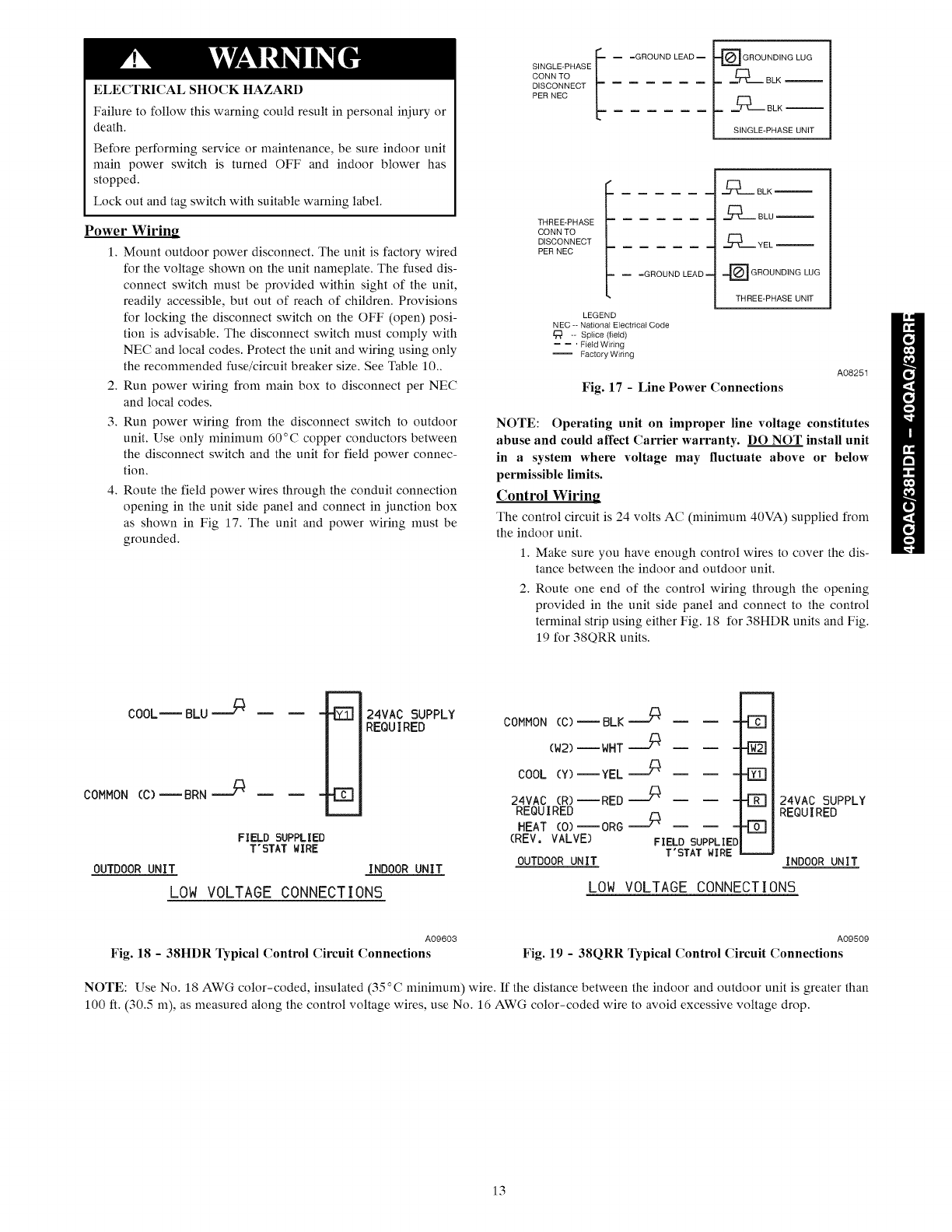
Power Wiring
1. Mount outdoor power disconnect. The unit is factory wired
for the voltage shown on the unit nameplate. The fused dis-
connect switch nmst be provided within sight of the unit,
readily accessible, but out of reach of children. Provisions
for locking the disconnect switch on the OFF (open) posi-
tion is advisable. The disconnect switch must comply with
NEC and local codes. Protect the unit and wiring using only
the recommended fuse/circuit breaker size. See Table 10..
2. Run power wiring from main box to disconnect per NEC
and local codes.
3. Run power wiring from the disconnect switch to outdoor
unit. Use only minimum 60°C copper conductors between
the disconnect switch and the unit for field power connec-
tion.
4. Route the field power wires through the conduit connection
opening in the unit side panel and connect in junction box
as shown in Fig 17. The unit and power wiring must be
grounded.
SINGLE-PHASE _ m =GROUNDLEADm _GROUNDINGLUG
I 7 2SE
THREE-PHASE
CONN TO
DISCONNECT
PER NEC
=GROUND LEAD
LEGEND
NEC -- National Electrical Code
-- Splice (field)
-- -- ' Field Wiring
-- Factory Widng
.-,/_ BLK
._.-- BLU
._._ YEL
_[_ GROUNDING LUG
THREE-PHASE UNIT
Fig. 17 -Line Power Connections
A08251
NOTE: Operating unit on improper line voltage constitutes
abuse and could affect Carrier warranty. DO NOT install unit
in a system where voltage may fluctuate above or below
permissible limits.
Control Wiring
The control circuit is 24 volts AC (mininmn_ 40VA) supplied from
the indoor unit.
1. Make sure you have enough control wires to cover the dis-
tance between the indoor and outdoor unit.
2. Route one end of the control wiring through the opening
provided in the unit side panel and connect to the control
ternfinal strip using either Fig. 18 for 38HDR units and Fig.
19 for 38QRR units.
COOLm BLU
COMMON (C)_BRN
FIELD SUPPLIED
T'STAT WIRE
24VAC SUPPLY
REQUIRED
42Z]
COMMON (C)_BLK ==''_
(W2)--WHT _
COOL (Y)--YEL _
24VAC (R)--RED _
REQUIRED
HEAT (O)--ORG _
(REV, VALVE) FIELD SUPPLIE
T'STAT WIRE
OUTDOORUNIT
-E]
-E]
-EZ]
OUTDOOR UNIT INDOOR UNIT
LOW VOLTAGE CONNECTIONS LOW VOLTAGE CONNECTIONS
24VAC SUPPLY
REQUIRED
INDOOR UNIT
A09603
Fig. 18 -38HDR Typical Control Circuit Connections
A09509
Fig. 19 -38QRR Typical Control Circuit Connections
NOTE: Use No. 18 AWG color-coded, insulated (35°C nfininmm) wire. If the distance between the indoor and outdoor unit is greater than
100 ft. (30.5 m), as measured along the control voltage wires, use No. 16 AWG color-coded wire to avoid excessive voltage drop.
13
ELECTRICAL DATA
38HDR
UNIT SIZE
018
024
030
036
048
060
V-PH-Hz
208/230-1-60
208/230-1-60
208/230-1-60
208/230-1-60
208/230-3-60
460-3-60
208/230-1-60
208/230-3-60
460-3-60
208/230-1-60
208/230-3-60
460-3-60
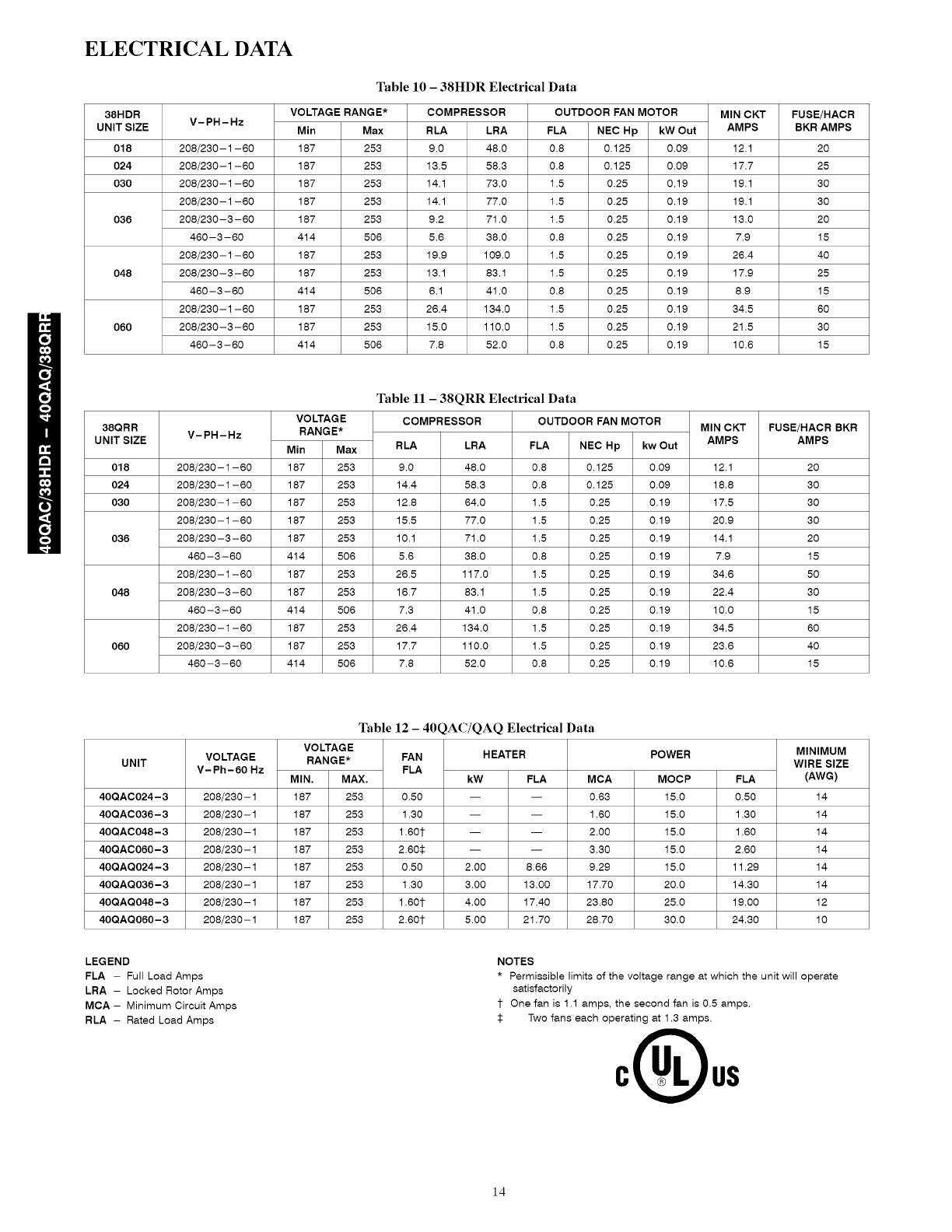
Table 10 - 38HDR Electrical Data
VOLTAGE RANGE* COMPRESSOR OUTDOOR FAN MOTOR
Min Max RLA LRA FLA NEC Hp kW Out
253 9.0 48.0 0.8 0.125 0.09
253 13.5 58.3 0.8 0.125 0.09
253 14.1 73.0 1.5 0.25 0.19
253 14.1 77.0 1.5 0.25 0.19
253 9.2 71.0 1.5 0.25 0.19
506 5.6 38.0 0.8 0.25 0.19
253 19.9 109.0 1.5 0.25 0.19
253 13.1 83.1 1.5 0.25 0.19
506 6.1 41.0 0.8 0.25 0.19
253 26.4 134.0 1.5 0.25 0.19
253 15.0 110.0 1.5 0.25 0.19
506 7.8 52.0 0.8 0.25 0.19
187
187
187
187
187
414
187
187
414
187
187
414
MIN CKT FUSE/HACR
AMPS BKR AMPS
12.1 20
17.7 25
19.1 30
19.1 30
13.0 20
7.9 15
26.4 40
17.9 25
8.9 15
34.5 60
21.5 30
10.6 15
38QRR
UNIT SIZE
018
024
030
036
048
060
V-PH-Hz
208/230-1-60
208/230-1-60
208/230-1-60
208/230-1-60
208/230-3-60
460-3-60
208/230-1-60
208/230-3-60
460-3-60
208/230-1-60
208/230-3-60
460-3-60
VOLTAGE
RANGE*
Min Max
187 253
187 253
187 253
187 253
187 253
414 506
187 253
187 253
414 506
187 253
187 253
414 506
Table 11 -38QRR Electrical Data
COMPRESSOR
RLA LRA
9.0 48.0
14.4 58.3
12.8 64.0
15.5 77.0
10.1 71.0
5.6 38.0
26.5 117.0
16.7 83.1
7.3 41.0
26.4 134.0
17.7 110.0
7.8 52.0
OUTDOOR FAN MOTOR MIN CKT
FLA NEC Hp kw Out AMPS
0.8 0.125 0.09 12.1
0.8 0.125 0.09 18.8
1.5 0.25 0.19 17.5
1.5 0.25 0.19 20.9
1.5 0.25 0.19 14.1
0.8 0.25 0.19 7.9
1.5 0.25 0.19 34.6
1.5 0.25 0.19 22.4
0.8 0.25 0.19 10.0
1.5 0.25 0.19 34.5
1.5 0.25 0.19 23.6
0.8 0.25 0.19 10.6
FUSE/HACR BKR
AMPS
2O
3O
3O
3O
2O
15
5O
3O
15
6O
4O
15
UNIT
40QAC024-3
40QAC036-3
40QAC048-3
40QAC060-3
40QAQ024-3
40QAQ036-3
40QAQ048-3
40QAQ060-3
VOLTAGE
V-Ph-60 Hz
208/230-1
208/230-1
208/230-1
208/230-1
208/230-1
208/230-1
208/230-1
208/230-1
Table 12 -40QAC/QAQ Electrical Data
VOLTAGE
RANGE* FAN HEATER POWER
FLA
MIN. MAX. kW FLA
187 253 0.50 -- --
187 253 1.30 -- --
187 253 1.60t --
187 253 2.60_ --
MCA
0.63
1.60
-- 2.00
-- 3.30
MOCP FLA
15.0 0.50
15.0 1.30
15.0 1.60
15.0 2.60
15.0 11.29
20.0 14.30
25.0 19.00
30.0 24.30
187 253 0.50 2.00
187 253 1.30 3.00
187 253 1.60t 4.00
187 253 2.60t 5.00
8.66 9.29
13.00 17.70
17.40 23.80
21.70 28.70
MINIMUM
WIRE SIZE
(AWG)
14
14
14
14
14
14
12
10
LEGEND
FLA - Full Load Amps
LRA - Locked Rotor Amps
MCA - Minimum Circuit Amps
RLA - Rated Load Amps
NOTES
*Permissible limits of the voltage range at which the unit will operate
satisfactorily
1- One fan is 1.1 amps, the second fan is 0.5 amps.
Two fans each operating at 1.3 amps.
14
SCHEMATIC - COOLING ONLY
IND)O { UNIT
2CS/2SO SO [_Rn-
,'LK--
ClSCON4ECT
>E_ NEC LU=
_LU
gLK k
THER"O,____T AT
PL2
)L2 --[LU X/_ WH T"--I
r'-SLk LJ _{: WHT 1I
DR FR2 I'L3 z HI _
FRI F¢ #L 8 ME
I J TH" I ! _( : I !E} <G !E) H [[!L}I -Lt YEL _/@fEL,,_ _:iL}I
I I .I." I "d6* _,<r,{<BR / I _
9L C3, O48, )r" _ "
?LJ _ 4HT --
t \ /:_> IFM?
8LK 230_' 048,0 C O['LY
_L_, ( N_)ENSATE I>JNP
A{;tE SORY _EPO'/E '_HEN
L_L_J TRAI _S i_ _CCE;SO Y IS U',E
_ NOTE ? --4HT_WHT
0_2 TBf TB PL[ S....!YE
WH
c_
PL2
-----t --
_ T_4
' ALTERN#TE T'STAT ,4/AIR
,WEE> F J['<TI _
,EE NTE
LEGEND NOTE5
{_} TER 4INAL CLARKE
0 TERt IN_L ,:JNMARKE }
• SPLICE
D TERHINAL sLeeK
FACTOR_ _II_INO
FIEL9 CO_:TROL WIRI_S
FIELd) PO,_ER WIr_I_(_
_ PRINTED CIRCUIT 80ARD
_CCESSO_Y OR OPTIONAL WIRIN6
AS_ '_[R SWEEP _OTOR
#JR 4EEP _IT;H
CAP CA >±CITOR
c_ CONTROL RELAY
[R DEFI@ T IELAY
EQUII .GN). E_UII :"El T POUiD
F>T FREEZE PROTECTI(N THE_MO TAT
F! FAN _ELAY
FU FUE
IFH INDO0_ FAN MOTO[
OL o _'ERLOAO
[CP PpI[ TE CI ICUIT OR#l}
PR 'UP DELAY _EL_
PL 'LUG
p ,lip MOTOR
P ,_P SliT )FF SW/TCH
<6SI)R S#FETY S_ITCH )ELAY RELAy
Tb TERMINAL BL(CK
T)R TI_E )ELAy RELAy
TR#% TRAN F'Rt ER
:_> I
-.] I
2. bI!E [[, ACCORDANCE_ITH ATION#L
ELECTRICALCOlE .E.C. AN[} LOCAL{:ODES.
3. TRAnSFORmERIS THERMALLYP_OTECTEt A_D
WILL RESET AUTOMATICALLY
IFM{S} ARE I_HERE_TLY THERmaLLYPROTECTEd.
S. USE COPPERCONDUCTOr,S ONLY.
_. WHENUSI_S THE_I_OSTATWITH AIR SWEEPFdNCTION:
¸YELLOWWIREFRO_ _3 TO BE CONNECTEDTO _SRI.
BL_¢I._ WIRE TO BE _I_;(:r)N_4ECTE_)FROM_SR_.
LEA/E ISLe'OKWIRE TIE W_>I_E[} TO YELLOWWIRE.
COMPONENT ARRANGEMENT
i iiiiii
E(;JIP (_N)
F]EL PO_E_
OI_CON_ECT PER NE¢
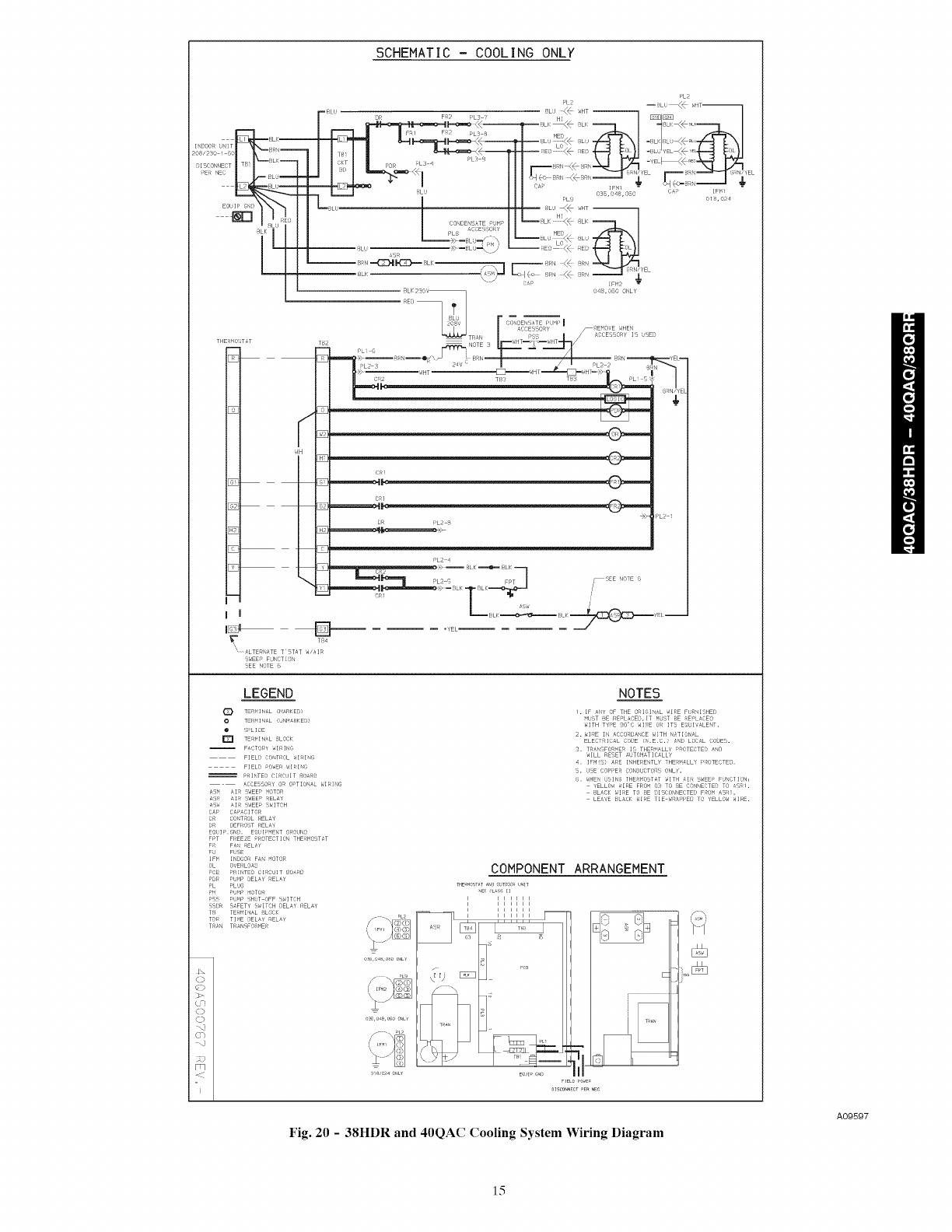
Fig. 20 -38HDR and 40QAC Cooling System Wiring Diagram
A09597
15
SCHEMATIC -HEATPUMP
LEGEND NOTES
TER<INAL ([ARKEP
O TER I'/_L ,:JNHARKE}
• SPLICE
D TERHINAL SLOCK
F_OTOF_Y_II_INS
FIELO CO_:TROLWIRI_C_
FIELO PO,_Er_WIthIN6
_ PRINTEr} CIRCUIT _O_RO
_CCESSORYOP OPTIOnaL WIfdN6
AS_ AIR SWEEPHOTOR
_SR AIR SWEEPRELAY
_'S_ AI_ SWEEPS_ITCH
CAP CAP_CITOI_
CR CONTROLI_EL'_Y
[}R OEFi_OSTRELAY
EeUII_._I_). EeUIP_ENT Si_OUNO
FPT FREEZE PROTECTIO_ THERMO_T_T
FR F_ rtEL_Y
FU FUSE
H_ HEATER£EL_Y
HTk HE_'TE_
HTT HE_'TER TE_P. THEf_MOST_'T
IFM INOOORFAN _OTOR
OL OVERLOAb
PC_ PRINTEr} CIRCUIT _C}_R[]
P_r_ Pt_r, DELAYRELAY
PL PLd5
P_ PtJ_P _IOTOR
PSS PU_P SHOT OFF SWITCH
_SO_ S_FET_ SWITCH _)EL_YRELAY
_ TErMINaL 8LOCK
T_)R TI_E _)ELAY_ELAY
T_A'_ TRANSFORMER
C>
(>
()
:.J
Fq
f:
2. _I!E if, #CCORDANOE_ITH ATION#L
ELEOT:(I}AL COlE .E.}.) _N[} LOCALCODE.
3. TRaNSFORmERIS THER_'ALLYPROTECTE_ A_40
_ILL RESET AUTOHATICALLY
IFM{S} ARE I_HEI_E_TLY THEI_I_LL_ I'ROTECTEO.
S. USE COPPEf_ CONOUCTO_SONLY.
_. _HEN USIN8 THE_I_OST_TWITH _IR SWEEP FdNOTION,
YELLO,_WI_E FRO_ (_S TO _E CONNECTEOTO _SRI.
BL_Cl._ ,_IRE TO _E OISCOXNECTEOF_O_.I_SRI.
LEAVE BL'_CK_II_E TIE _PPE[} TO _ELLOWWIRE.
7. J'JMPE_ _IRE {0 TO Y_) REOUIREOWHENHEATPU_4P
INO00_ UNIT IS bSED _ITH COOLIN6 ONLY08TOOOk
UNIT _IRE _UST BE FIEL[} SUPI'LIE[_.
COMPONENT ARRANGEMENT
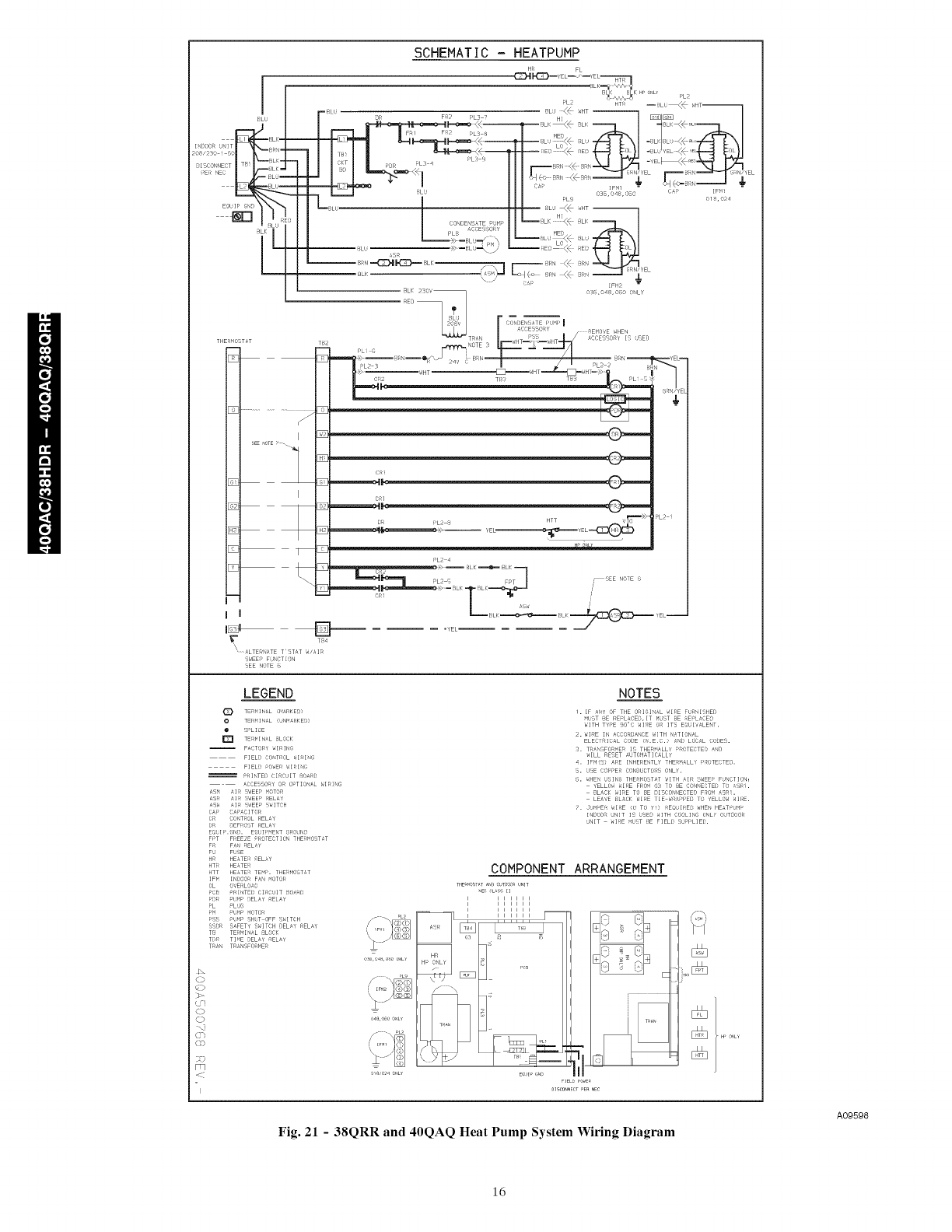
Fig. 21 -38QRR and 40QAQ Heat Pump System Wiring Diagram
A09598
16
Complete Indoor Piping
The piping to the indoor unit can be routed from the back, side and
top. If the unit is being piped from the top or the side see note
below.
1. On heat 400A0024 - 048, the cooling piston {indoor} is
shipped in the factory installed metering device with the in-
door unit. Use Table 6 to verify that you have the correct
piston size for the system being installed.
2. Run the line set and the control wiring from the outdoor to
the indoor unit through the hole in the wall. Keep the piping
general guidelines in mind.
3. Cut the liquid and suction line to the correct length using a
tube cutter.
4. Remove the flare nuts from the indoor piping connections.
Install them onto the liquid and suction lines and make flare
connections.
5. Apply a small amount of refrigerant oil to the flare connec-
tion and tubing.
6. Align the tubing with the refrigerant connections on the in-
door unit.
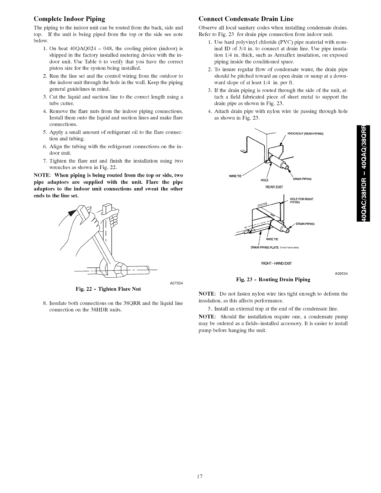
7. Tighten the flare nut and finish the installation using two
wrenches as shown in Fig. 22.
NOTE: When piping is being routed from the top or side, two
pipe adaptors are supplied with the unit. Flare the pipe
adaptors to the indoor unit connections and sweat the other
ends to the line set.
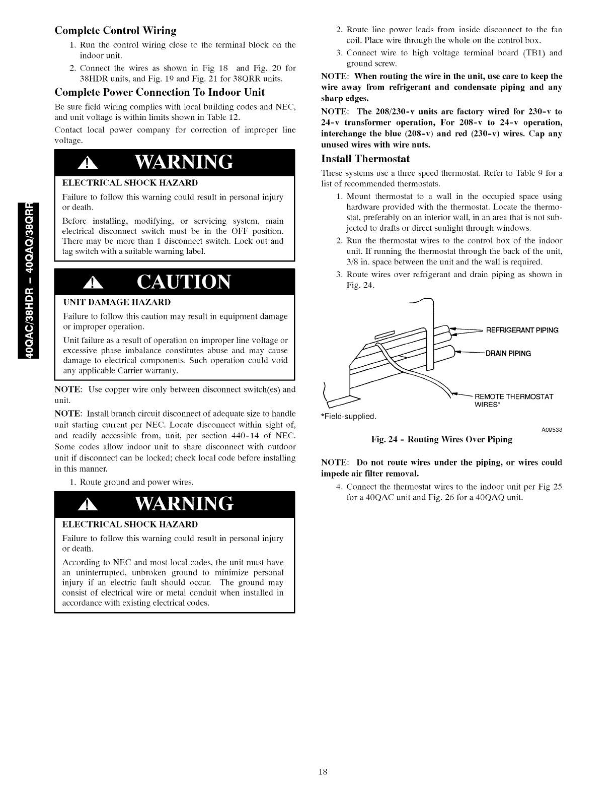
Connect Condensate Drain Line
Observe all local sanitary codes when installing condensate drains.
Refer to Fig. 23 for drain pipe connection from indoor unit.
1. Use hard polyvinyl chloride (PVC) pipe material with nom-
inal ID of 3/4 in. to connect at drain line. Use pipe insula-
tion 1/4 in. thick, such as Armaflex insulation, on exposed
piping inside the conditioned space.
2. To insure regular flow of condensate water, the drain pipe
should be pitched toward an open drain or sump at a down-
ward slope of at least 1/4 in. per ft.
3. If the drain piping is routed through the side of the unit, at-
tach a field fabricated piece of sheet metal to support the
drain pipe as shown in Fig. 23.
4. Attach drain pipe with nylon wire tie passing through hole
as shown in Fig. 23.
WIRE TIE
KNOCKOUT {REAR PIPING)
HOLE DRAIN PIPING
REAR EXIT
HOLE FOR RIGHT
PIPING
,_._ DRAIN PIPING
DRAIN PIPING PLATE (F_eldFabrtcaed)
A07354
Fig. 22 -Tighten Flare Nut
8. Insulate both connections on the 38QRR and the liquid line
connection on the 38HDR units.
RIGHT- HAND EXIT
A09534
Fig. 23 -Routing Drain Piping
NOTE: Do not fasten nylon wire ties tight enough to deform the
insulation, as this affects performance.
5. Install an external trap at the end of the condensate line.
NOTE: Should the installation require one, a condensate pump
may be ordered as a fields-installed accessory. It is easier to install
pump before hanging the unit.
17
Complete Control Wiring
1. Run the control wiring close to the ternfinal block on the
indoor unit.
2. Connect the wires as shown in Fig 18 and Fig. 20 for
38HDR units, and Fig. 19 and Fig. 21 for 38QRR units.
Complete Power Connection To Indoor Unit
Be sure field wiring complies with local building codes and NEC,
and unit voltage is within linfits shown in Table 12.
Contact local power company for correction of improper line
voltage.
ELECTRICALSHOCK HAZARD
Failure to follow this warning could result in personal injury
or death.
Before installing, modifying, or servicing system, main
electrical disconnect switch nmst be in the OFF position.
There may be more than 1 disconnect switch. Lock out and
tag switch with a suitaMe warning label.
[]NIT DAMAGE HAZARD
Failure to follow this caution may result in equipment damage
or improper operation.
Unit failure as a result of operation on improper line voltage or
excessive phase imbalance constitutes abuse and may cause
damage to electrical components. Such operation could void
any applicable Carrier warranty.
NOTE: Use copper wire only between disconnect switch(es) and
unit.
NOTE: Install branch circuit disconnect of adequate size to handle
unit starting current per NEC. Locate disconnect within sight of,
and readily accessible from, unit, per section 440-14 of NEC.
Some codes allow indoor unit to share disconnect with outdoor
unit if disconnect can be locked; check local code before installing
in this manner.
1. Route ground and power wires.
ELECTRICALSHOCK HAZARD
Failure to follow this warning could result in personal injury
or death.
According to NEC and most local codes, the unit must have
an uninterrupted, unbroken ground to nfininfize personal
iniury if an electric fault should occur. The ground may
consist of electrical wire or metal conduit when installed in
accordance with existing electrical codes.
2. Route line power leads from inside disconnect to the fan
coil. Place wire through the whole on the control box.
3. Connect wire to high voltage ternfinal board (TBI) and
ground screw.
NOTE: When routing the wire in the unit, use care to keep the
wire away from refrigerant and condensate piping and any
sharp edges.
NOTE: The 208/230-v units are factory wired for 230-v to
24-v transformer operation, For 208-v to 24-v operation,
interchange the blue (208-v) and red (230-v) wires. Cap any
unused wires with wire nuts.
Install Thermostat
These
list of
1.
2,
3,
systems use a three speed thermostat. Refer to Table 9 for a
recommended thermostats.
Mount thermostat to a wall in the occupied space using
hardware provided with the thermostat. Locate the thermo-
stat, preferably on an interior wall, in an area that is not sub-
jected to drafts or direct sunlight through windows.
Run the thermostat wires to the control box of the indoor
unit. If running the thermostat through the back of the unit,
3/8 in. space between the unit and the wall is required.
Route wires over refrigerant and drain piping as shown in
Fig. 24.
_ REFRIGERANTPIPING
*Field-supplied.
A09533
Fig. 24 - Routing Wires Over Piping
NOTE: Do not route wires under the piping, or wires could
impede air filter removal.
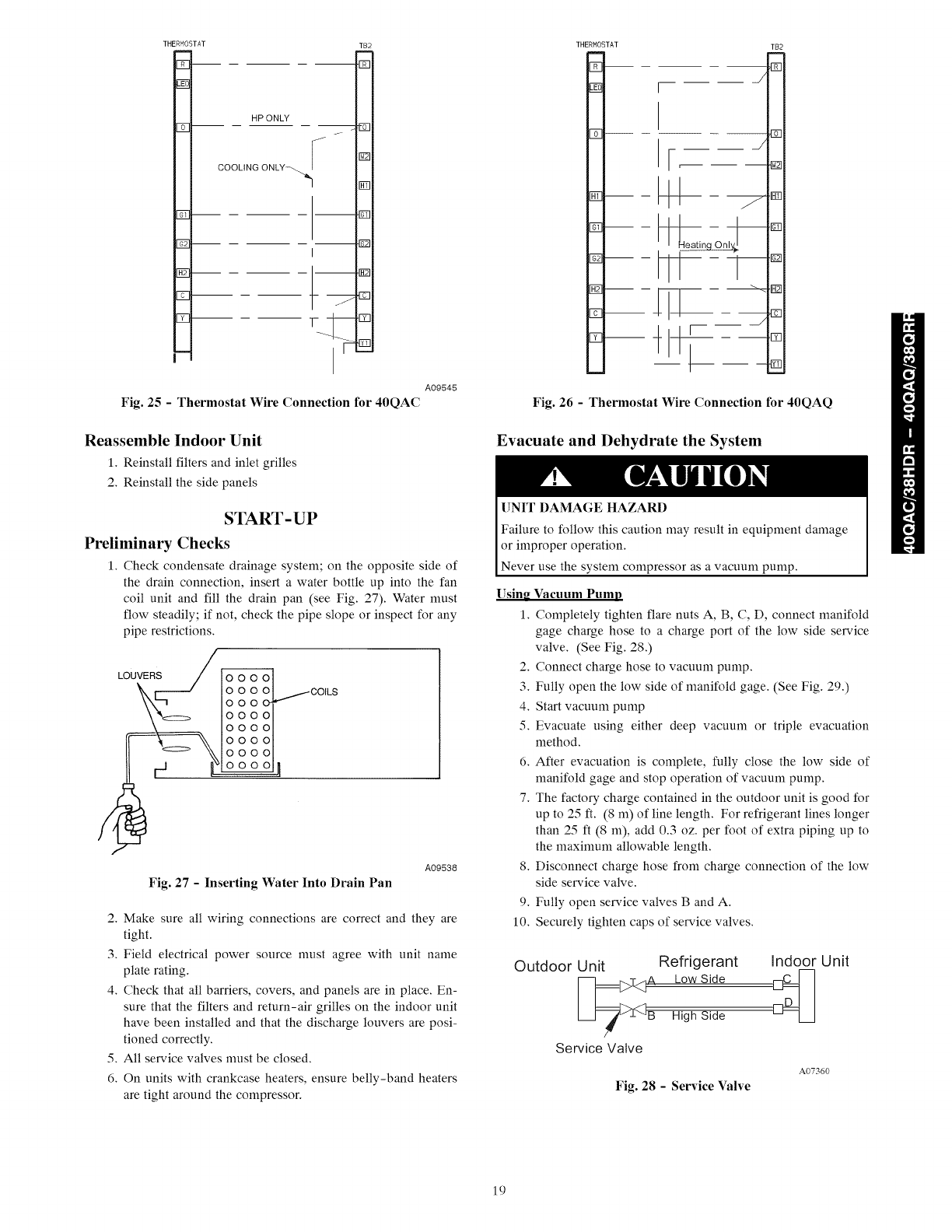
4. Connect the thermostat wires to the indoor unit per Fig 25
for a 40QAC unit and Fig. 26 for a 40QAQ unit.
18
THERHOSTAT
FT-
FT
H_-
FT
FT
HP ONLY
f
COOLING ONLY--_ _
TB2
D
D
r_q
E0
D
D
rfq
Fig. 25 -Thermostat Wire Connection for 40QAC
A09545
Reassemble Indoor Unit
1. Reinstall filters and inlet grilles
2. Reinstall the side panels
START-UP
Preliminary Checks
1. Check condensate drainage system; on the opposite side of
the drain connection, insert awater bottle up into the fan
coil unit and fill the drain pan (see Fig. 27). Water must
flow steadily; if not, check the pipe slope or inspect for any
pipe restrictions.
LOUVERS
Fig. 27 - Inserting Water Into Drain Pan
A09538
2. Make sure all wiring connections are correct and they are
tight.
3. Field electrical power source must agree with unit name
plate rating.
4. Check that all barriers, covers, and panels are in place. En-
sure that the filters and return-air grilles on the indoor unit
have been installed and that the discharge louvers are posi-
tioned correctly.
5. All service valves must be closed.
6. On units with crankcase heaters, ensure belly-band heaters
are tight around the compressor.
THERMOSTAT
m
E
E
B-
E
IT
EI
J
r
r J
I
T82
[]
m
[]
Fig. 26 - Thermostat Wire Connection for 40QAQ
Evacuate and Dehydrate the System
UNIT DAMAGE HAZARD
Failure to follow this caution may result in equipment damage
or improper operation.
Never use the system compressor as a vacuum pump.
Using Vacuum Pump
1. Completely tighten flare nuts A, B, C, D, connect manifold
gage charge hose to a charge port of the low side service
valve. (See Fig. 28.)
2. Connect charge hose to vacuum pump.
3. Fully open the low side of manifold gage. (See Fig. 29.)
4. Start vacuum pump
5. Evacuate using either deep vacuum or triple evacuation
method.
6. After evacuation is complete, fully close the low side of
manifold gage and stop operation of vacuum pump.
7. The factory charge contained in the outdoor unit is good for
up to 25 ft. (8 m) of line length. For refrigerant lines longer
than 25 ft (8 m), add 0.3 oz. per foot of extra piping up to
the maximum allowable length.
8. Disconnect charge hose from charge connection of the low
side service valve.
9. Fully open service valves B and A.
10. Securely tighten caps of service valves.
Outdoor Unit Refrigerant
_B Low Side
High Side
Service Valve
Indoor Unit
A07360
Fig. 28 -Service Valve
19
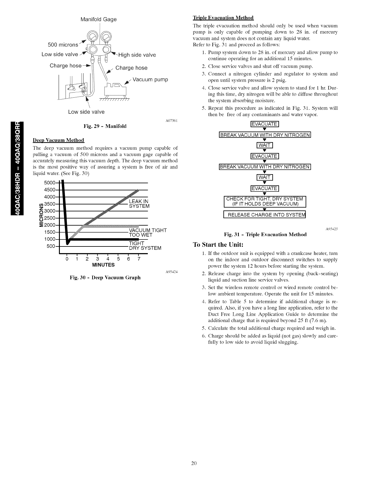
Manifold Gage
500 microns "
Low side valve _Z.)
Charge hose-_
High side valve
/Charge hose
Vacuum pump
Low side valve
A07361
Fig. 29 - Manifold
Deep Vacuum Method
The deep vacuum method requires a vacuum pump capable of
pulling a vacuum of 500 microns and a vacuum gage capable of
accurately measuring this vacuum depth. The deep vacuum method
is the most
liquid water.
o
_ositive way of assuring a system is free of air and
See Fig. 30)
LEAK IN
SYSTEM
VACUUM TIGHT
TOO WET
TIGHT
DRY SYSTEM
1234567
MINUTES
Fig. 30 -Deep Vacuum Graph
A95424
Triple Evacuation Method
The triple evacuation method should only be used when vacuum
pump is only capable of pumping down to 28 in. of mercury
vacuum and system does not contain any liquid water.
Refer to Fig. 31 and proceed as follows:
1. Pump system down to 28 in. of mercury and allow pump to
continue operating for an additional 15 minutes.
2. Close service valves and shut off vacuum pump.
3. Connect a nitrogen cylinder and regulator to system and
open until system pressure is 2 psig.
4. Close service valve and allow system to stand for 1 hr. Dur-
ing this time, dry nitrogen will be able to diffuse throughout
the system absorbing moisture.
5. Repeat this procedure as indicated in Fig. 31. System will
then be free of any contaminants and water vapor.
IEVACUATEI
IBREAK VACUUM WITH DRY NITROGEN I
[28!3
IEVACUATEI
IBREAK VACUUM WITH DRY NITROGEN I
IEvACuATEI
ICHECKFORT,GHTOR¥SYSTEMI
(IF IT HOLDS DEEP VACUUM)
I RELEASEC,ARGE,NTOSYSTE I
A95425
Fig. 31 - Triple Evacuation Method
To Start the Unit:
1. If the outdoor unit is equipped with a crankcase heater, turn
on the indoor and outdoor disconnect switches to supply
power the system 12 hours before starting the system.
2. Release charge into the system by opening (back-seating)
liquid and suction line service valves.
3. Set the wireless remote control or wired remote control be-
low ambient temperature. Operate the unit for 15 minutes.
4. Refer to Table 5 to determine if additional charge is re-
quired. Also, if you have a long line application, refer to the
Duct Free Long Line Application Guide to determine the
additional charge that is required beyond 25 ft (7.6 m).
5. Calculate the total additional charge required and weigh in.
6. Charge should be added as liquid (not gas) slowly and care-
fully to low side to avoid liquid slugging.
20
OPERATING SEQUENCE
Ceiling-suspended fan coil units have a relay board which controls
system operation in response to a room thermostat. The user may
manually select any one of 3 fan speeds for unit operation. The
discharge louvers on the unit can be stationary or swing
continuously. A switch located at the bottom of the unit will turn
the swing flmction on and off.
Ceiling-suspended systems may be equipped with an accessory
power ventilation kit and/or condensate pump.
FAN OPERATION -- Fan coils are capable of 3-speed
operation. See thermostat instructions for fan speed selection.
When the fan(s) is operating in medium or high speed and the unit
is equipped with the power ventilation kit, the ventilation fan will
operate to provide fresh air.
COOLING MODE OPERATION -- When the room thermostat
senses a demand for cooling, the fan coil relay board is energized.
The indoor fan(s) will start in the selected speed (if it is not already
operating). The reversing valve (heat pump only) will energize for
cooling operation.
The internal condensate pump (if so equipped) runs whenever the
reversing valve is energized (heat pump only) and/or the unit is in
cooling. As long as the condensate float switch and freeze
protection thermostat are closed, the cooling relays in the fan coil
unit will close. This energizes the compressor and outdoor fan in
the outdoor unit.
The compressor will continue to operate until the room thermostat
is satisfied. When the cooling demand is satisfied, the compressor
and outdoor fan will stop. If the system is in the AUTO. position,
the indoor fan will stop with the compressor.
If the unit has the accessory ventilation kit, the ventilation fan will
operate whenever the indoor fan is set for medium or high speed.
HEAT PUMP OPERATION -- When the room thermostat
senses a demand for heating the indoor fan will start in the selected
speed (if not already operating), and the reversing valve will not be
energized.
The internal condensate pump (if supplied) and freeze protection
thermostat are not operated during heating operation. The control
relay (CR2) closes, and the compressor and outdoor fan are
energized through the defrost board (DFB), which is located in the
outdoor unit. The microprocessor logic in the DFB is energized
when the compressor starts, and the defrost timer runs. Once every
90 minutes (factory default setting) of compressor run time, the
DFB logic checks the defrost thermostat (DFT). If the DFT is
open, the unit continues in heating operation. If the DFT is closed,
the DFB switches the unit to defrost mode. The timing on the DFB
may be set at either 30, 50, or 90 minutes.
DEFROST (Heat Pump Only) -- The DFB energizes the RVS
(reversing valve solenoid), and the reversing valve switches to the
cooling position. The K1 relay on the DFB opens and the outdoor
fan stops. The W2 contact on the DFB is also energized, which in
turn energizes the defrost relay on the fan coil relay board, turns off
the electric heater and stops the indoor fan.
The DFB logic checks the 10-minute defrost timer and the DFT. If
the DFT opens in less than 10 nfinutes, the DFB switches the unit
back to normal heating operation. If the DFT remains closed, the
DFB switches the unit back to heating operation after 10 minutes.
When the DFB changes back to heating mode, the RVR (reversing
valve relay) is de-energized and the reversing valve switches back
to heating operation. Both the outdoor and indoor fans come back
on, and if necessary, the electric heater also turns on. SYSTEM
SAFETIES -- The system is equipped with the following safety
devices to protect system components: Indoor coil freeze
protection thermostat -- If a coil temperature of 28 °F (-2.22 ° C) or
lower is sensed, the compressor and outdoor fan will be shut down
until the coil temperature exceeds 28°F (-2.22°C). The indoor fan
will continue to run. Condensate float switch (units equipped with
accessory condensate pump, cooling cycle only) -- If the level of
condensate in the drain pan rises too high, the condensate float
switch will turn the system off.
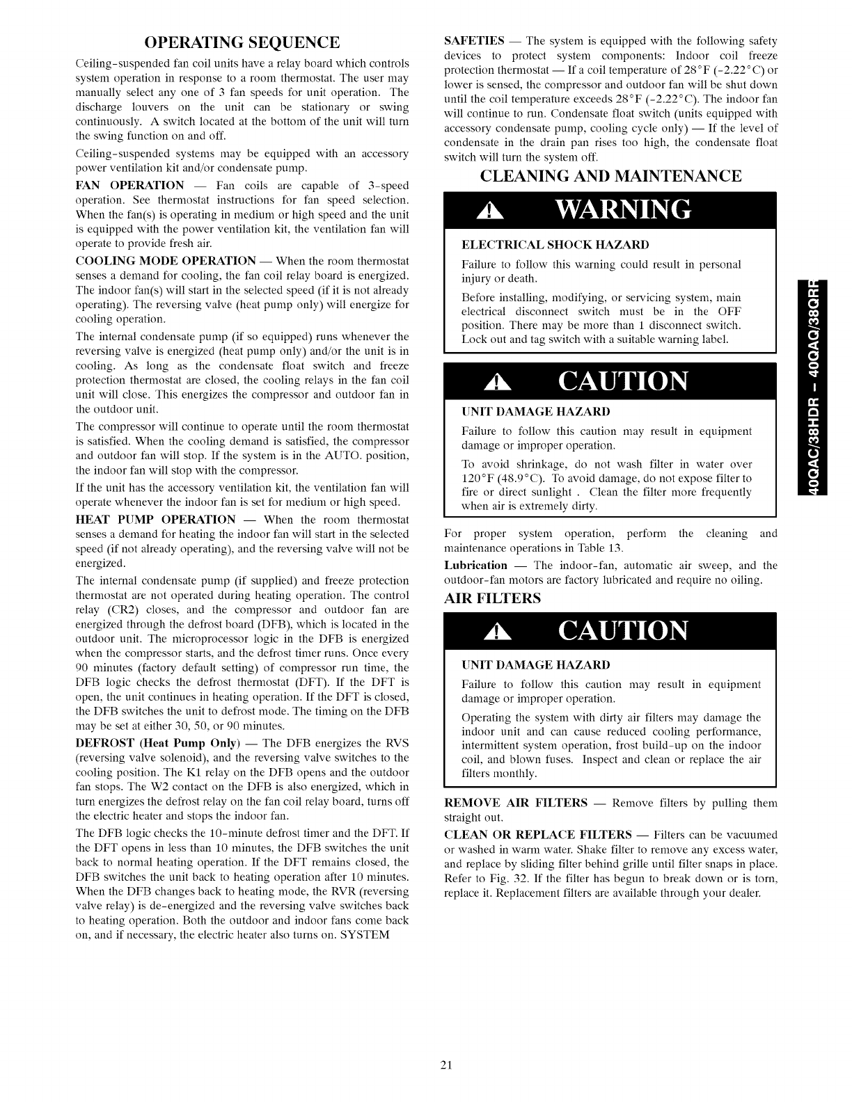
CLEANING AND MAINTENANCE
ELECTRICALSHOCK HAZARD
Failure to follow this warning could result in personal
injury or death.
Before installing, modifying, or servicing system, main
electrical disconnect switch must be in the OFF
position. There may be more than 1 disconnect switch.
Lock out and tag switch with a suitable warning label.
UNIT DAMAGE HAZARD
Failure to follow this caution may result in equipment
damage or improper operation.
To avoid shrinkage, do not wash filter in water over
120°F (48.9°C). To avoid damage, do not expose filter to
fire or direct sunlight . Clean the filter more frequently
when air is extremely dirty.
For proper system operation, perform the cleaning and
maintenance operations in Table 13.
Lubrication -- The indoor-fan, automatic air sweep, and the
outdoor-fan motors are factory lubricated and require no oiling.
AIR FILTERS
UNIT DAMAGE HAZARD
Failure to follow this caution may result in equipment
damage or improper operation.
Operating the system with dirty air filters may damage the
indoor unit and can cause reduced cooling performance,
intermittent system operation, frost build-up on the indoor
coil, and blown fuses. Inspect and clean or replace the air
filters monthly.
REMOVE AIR FILTERS -- Remove filters by pulling them
straight out.
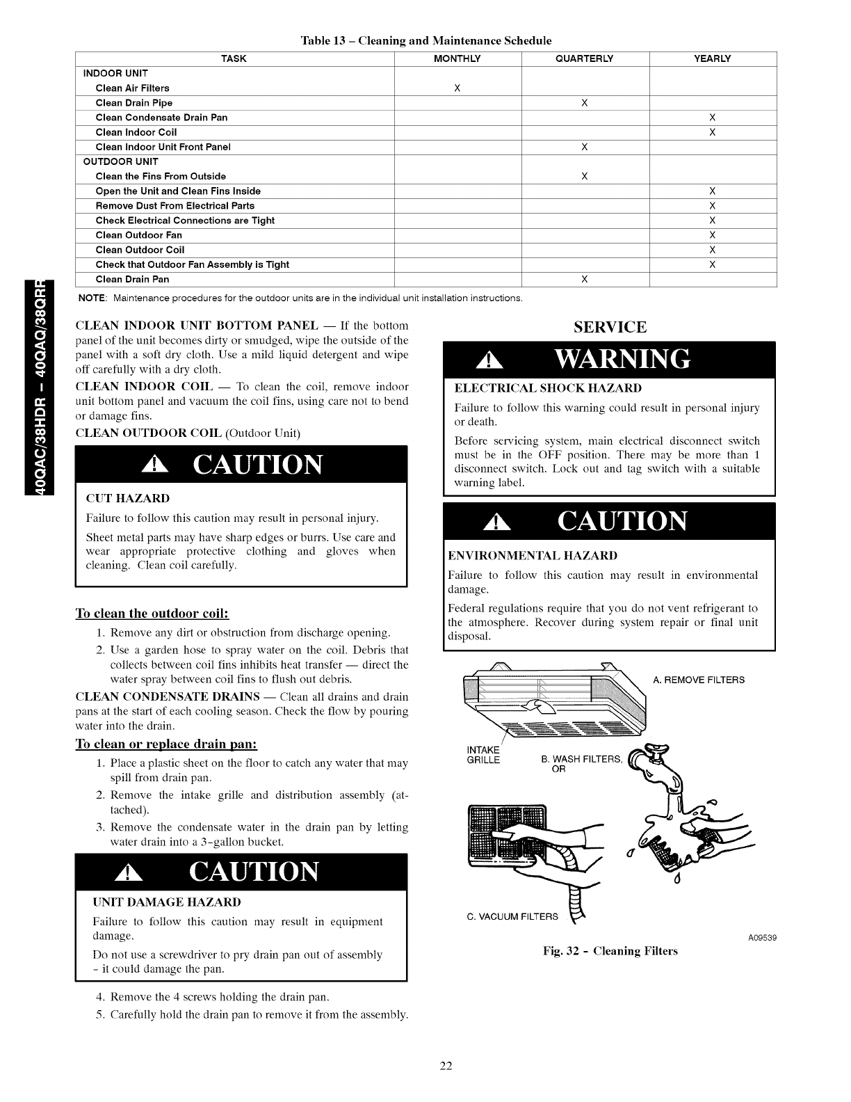
CLEAN OR REPLACE FILTERS -- Filters can be vacuumed
or washed in warm water. Shake filter to remove any excess water,
and replace by sliding filter behind grille until filter snaps in place.
Refer to Fig. 32. If the filter has begun to break down or is torn,
replace it. Replacement filters are available through your dealer.
21
TASK
INDOOR UNIT
Clean Air Filters X
Clean Drain Pipe
Clean Condensate Drain Pan
Clean Indoor Coil
Clean Indoor Unit Front Panel
OUTDOOR UNIT
Clean the Fins From Outside
Open the Unit and Clean Fins Inside
Remove Dust From Electrical Parts
Check Electrical Connections are Tight
Clean Outdoor Fan
Clean Outdoor Coil
Check that Outdoor Fan Assembly is Tight
Clean Drain Pan
NOTE: Maintenance procedures for the outdoor units are in the individual unit installation instructions.
Table 13 - Cleaning and Maintenance Schedule
MONTHLY QUARTERLY YEARLY
X
X
X
X
X
X
X
X
X
X
X
X
CLEAN INDOOR UNIT BOTTOM PANEL -- If the bottom
panel of the unit becomes dirty or smudged, wipe the outside of the
panel with a soft dry cloth. Use a mild liquid detergent and wipe
off carefully with a dry cloth.
CLEAN INDOOR COIL -- To clean the coil, remove indoor
unit bottom panel and vacuum the coil fins, using care not to bend
or damage fins.
CLEAN OUTDOOR COIL (Outdoor []nit)
CUT HAZARD
Failure to follow this caution may result in personal iniury.
Sheet metal parts may have sharp edges or burrs. Use care and
wear appropriate protective clothing and gloves when
cleaning. Clean coil carefully.
To clean the outdoor coil:
1. Remove any dirt or obstruction from discharge opening.
2. Use a garden hose to spray water on the coil. Debris that
collects between coil fins inhibits heat transfer -- direct the
water spray between coil fins to flush out debris.
CLEAN CONDENSATE DRAINS -- Clean all drains and drain
pans at the start of each cooling season. Check the flow by pouring
water into the drain.
To clean or replace drain pan:
1. Place a plastic sheet on the floor to catch any water that may
spill from drain pan.
2. Remove the intake grille and distribution assembly (at-
tached).
3. Remove the condensate water in the drain pan by letting
water drain into a 3-gallon bucket.
[]NIT DAMAGE HAZARD
SERVICE
ELECTRICALSHOCK HAZARD
Failure to follow this warning could result in personal injury
or death.
Before servicing system, main electrical disconnect switch
must be in the OFF position. There may be more than 1
disconnect switch. Lock out and tag switch with a suitable
warning label.
ENVIRONMENTAL HAZARD
Failure to follow this caution may result in environmental
damage.
Federal regulations require that you do not vent refrigerant to
the atmosphere. Recover during system repair or final unit
disposal.
A. REMOVE FILTERS
INTAKE
GRILLE B. WASH FILTERS, (((" "_
OR
Failure to follow this caution may result in equipment
damage,
Do not use a screwdriver to pry drain pan out of assembly
- it could damage the pan.
4. Remove the 4 screws holding the drain pan.
5. Carefully hold the drain pan to remove it from the assembly.
C. VACUUM FILTERS
Fig. 32 - Cleaning Filters
A09539
22
Before Calling for Service
Save the cost of a service call by doing the following:
1. Be sure main power to system is turned on.
2. Press Mode button until OFF is displayed. Wait 5 minutes.
3. Press Mode button until either COOL or HEAT is displayed
(as desired).
4. Adjust thermostat set point to desired room temperature. If
system starts within a few minutes, service may not be ne-
cessary. If system does not operate properly, check Table 14
for typical solutions.
IF SYSTEM FAILS TO OPERATE -- Be sure:
• unit ON/OFF switch is in ON position
• fuse or circuit breaker is not tripped
FRESH AIR INSTALLATION OPTION
The units have an installation option, which allows for field
installation of fresh air ventilation. Plan the installation carefully.
Before beginning, measure carefully and follow acceptable
building practices, NEC, and local codes.
Ventilation-Air Accessory -- Refer to ventilation air accessory
installation instructions.
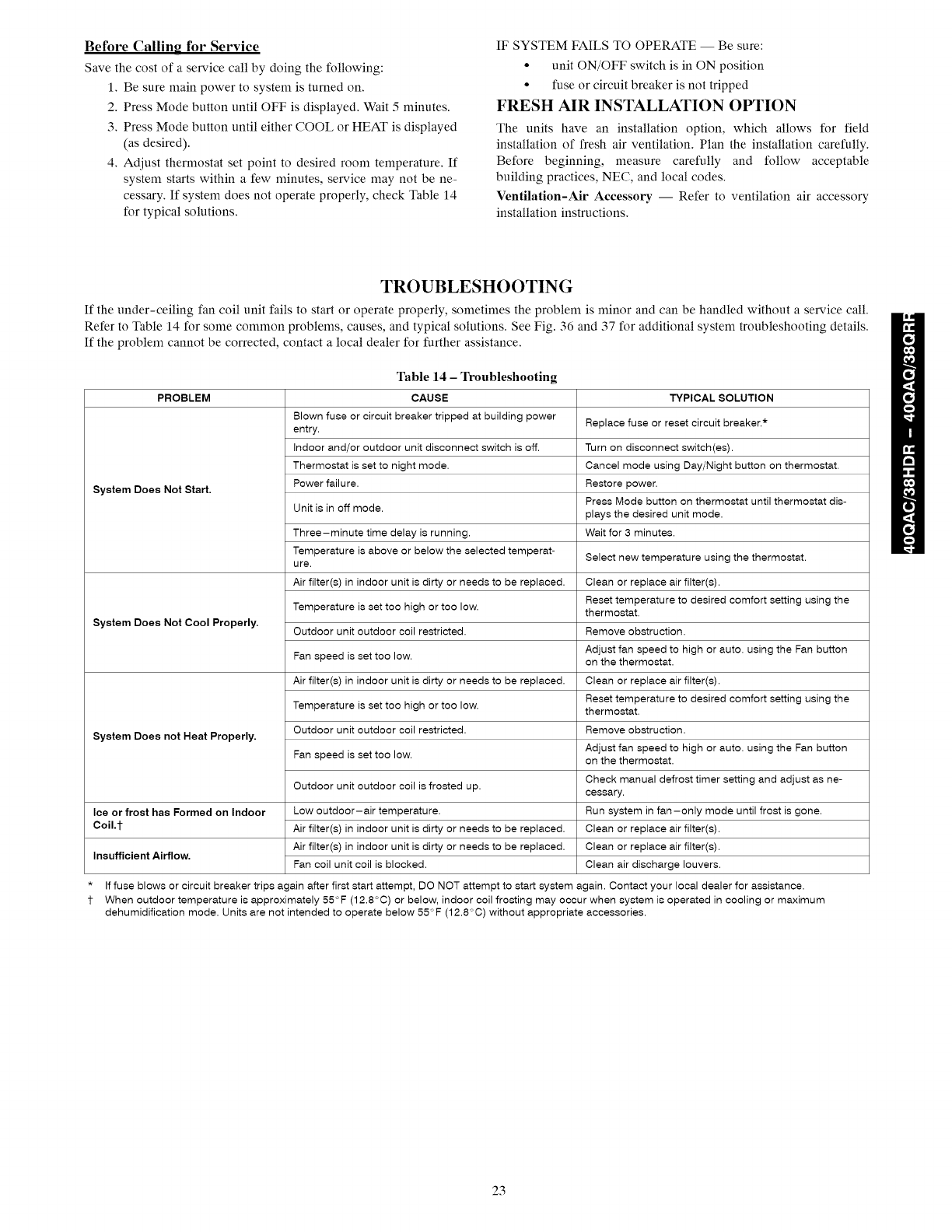
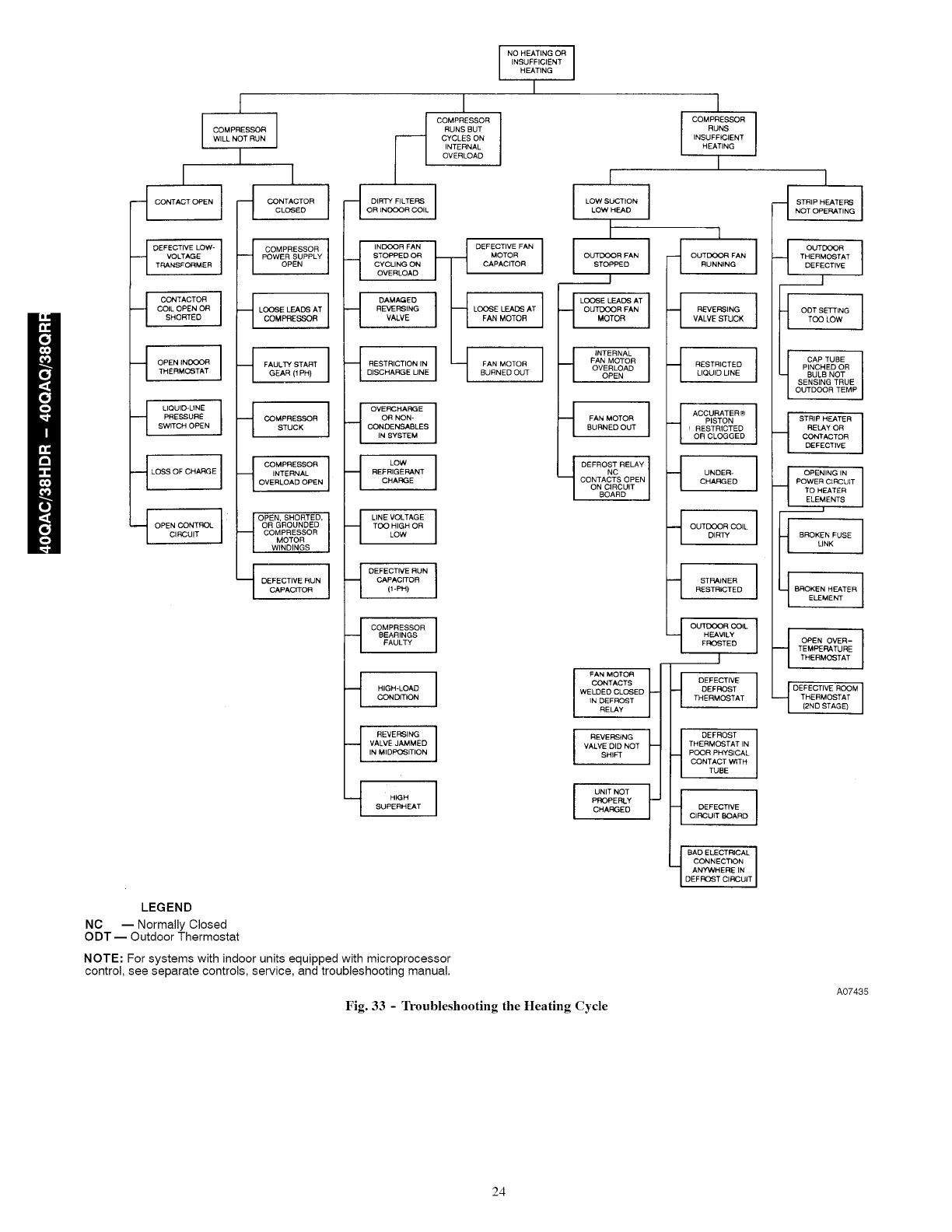
TROUBLESHOOTING
If the under-ceiling fan coil unit fails to start or operate properly, sometimes the problem is minor and can be handled without a service call.
Refer to Table 14 for some common problems, causes, and typical solutions. See Fig. 36 and 37 for additional system troubleshooting details.
If the problem cannot be corrected, contact a local dealer for further assistance.
Table 14 - Troubleshooting
PROBLEM
System Does Not Start.
System Does Not Cool Properly.
System Does not Heat Properly.
Ice or frost has Formed on Indoor
Coil J-
Insufficient Airflow.
CAUSE
Blown fuse or circuit breaker tripped at building power
entry.
Indoor and/or outdoor unit disconnect switch is off.
Thermostat is set to night mode.
Power failure.
Unit is in off mode.
Three-minute time delay is running.
Temperature is above or below the selected temperat-
ure.
Air filter(s) in indoor unit is dirty or needs to be replaced.
Temperature is set too high or too low.
Outdoor unit outdoor coil restricted.
Fan speed is set too low.
Air filter(s) in indoor unit is dirty or needs to be replaced.
Temperature is set too high or too low.
Outdoor unit outdoor coil restricted.
Fan speed is set too low.
Outdoor unit outdoor coil is frosted up.
Low outdoor-air temperature.
Air filter(s) in indoor unit is dirty or needs to be replaced.
Air filter(s) in indoor unit is dirty or needs to be replaced.
Fan coil unit coil is blocked.
TYPICAL SOLUTION
Replace fuse or reset circuit breaker.*
Turn on disconnect switch(as).
Cancel mode using Day/Night button on thermostat.
Restore power.
Press Mode button on thermostat until thermostat dis-
plays the desired unit mode.
Wait for 3 minutes.
Select new temperature using the thermostat.
Clean or replace air filter(s).
Reset temperature to desired comfort setting using the
thermostat.
Remove obstruction.
Adjust fan speed to high or auto. using the Fan button
on the thermostat.
Clean or replace air filter(s).
Reset temperature to desired comfort setting using the
thermostat.
Remove obstruction.
Adjust fan speed to high or auto. using the Fan button
on the thermostat.
Check manual defrost timer setting and adjust as ne-
cessary.
Run system in fan-only mode until frost is gone.
Clean or replace air filter(s).
Clean or replace air filter(s).
Clean air discharge louvers.
If fuse blows or circuit breaker trips again after first start attempt, DO NOT attempt to start system again. Contact your local dealer for assistance.
When outdoor temperature is approximately 55°F (12.8°C) or below, indoor coil frosting may occur when system is operated in cooling or maximum
dehumidification mode. Units are not intended to operate below 55°F (12.8°C) without appropriate accessories.
23
I
--[CONTAOTO ENJ
-"-t DEFECTIVE LOW- I
VOLTAGE
TRANSFORMER
_1 CONTACTOR I
COIL OPEN OR
SHORTED
_1 OPEN INDOOR ITHERMOSTAT
_-t LIQUID-LINE I
PRESSURE
SWITCH OPEN
_-_ LOSS OF CHARGE
_{ OPEN CONTROLCIRCUIT
t
COMPRESSOR
WILL NOT RUN
II
NTAOTOR1CLOSED
_t COMPRESSOR I
POWER SUPPLY
OPEN
_-t LOOSE LEAD'S AT I
COMPRESSOR
GEAR 11PHI
I
NO HEATING OR I
I
INSUFFICIENT
HEATING
I
I
COMPRESSOR J
RUNS BUT
CYCLES ON
INTERNAL
OVERLOAD
---[ DIRTY FILTERS ]OR INDOOR COIL
._ INDOOR FAN DEFECTIVE FAN
STOPPED OR MOTOR
CYCLING ON CAPACITOR
OVERLOAD
_ DAMAGED ]
REVERSING LOOSE LEADS AT
VALVE FAN MOTOR
_-[ RESTRICTION IN FAN MOTORDISCHARGE LINE BURNED OUT
[
ILOWSOCT'ONILOW HEAD
iISTOPPED
_.____.._1
_1 LOOSE LEADS AT I
OUTDOOR FAN
MOTOR
_1 INTERNAL I
FAN MOTOR
OVERLOAD
OPEN
I
COMPRESSOR I
RUNS
INSUFFICIENT
HEATING
I
1
OUT RFANIRUNNING
--[ REVERSING IVALVE STUCK
--[ RESTRICTED ILIQUID LINE
I
-1 STR'PHEATE_INOT OPERATING
fOUTDOOR
THERMOSTAT
DEFECTIVE
______J
ODT SET-rING
TOO LOW
CAP TUBE
PINCHED OR
BULB NOT
SENSING TRUE
_1 COMPRESSOR ISTUCK
___ COMPRESSOR ]
INTERNAL
OVERLOAD OPEN
___OPEN'SHORTED' I
OR GROUNDED
COMPRESSOR
MOTOR
WINDINGS
_l DEFECTIVE RUN ICAPACITOR
"_1 OVERCHARGE I
OR NON-
CONDENSABLES
IN SYSTEM
LOW
REFRIGERANT
CHARGE
_--I LINE VOLTAGE
TOO HIGH OR
LOW
----I DEFECTIVE RUN I
CAPACITOR
(1-PH)
_1 COMPRESSOR I
BEARINGS
FAULTY
_1 HIGH-LOAD ICONDITION
"_1 REVERSING I
VALVE JAMMED
IN MIDPOSmON
_t HIGH I
SUPERHEAT
_1 FAN MOTOR IBURNED OUT
.__ DEFROST RELAY
NC
CONTACTS OPEN
ON CIRCUIT
BOARD
I FAN MOTOR
CONTACTS
WELDED CLOSED
IN DEFROST
RELAY
I REVERSING
VALVE DID NOT
SHIFT
I UNITNOT t'-
PROPERLY
CHARGED
__{ ACCURATER®
PISTON
IRESTRICTED
OR CLOGGED
_1 UNDER- ICHARGED
"'t OUTDOOR COIL IDIRTY
_1 STRAINER IRESTRICTED
_1 OUTDOOR COIL ]
HEAVILY
FROSTED
I
DEFECTIVE I -'_
DEFROST
THERMOSTAT
OUTDOOR TEMP
I_1 STRIP HEATER
RELAY OR
CONTACTOR
DEFECTIVE
OPENING IN 1
POWER CIRCUIT
TO HEATER
ELEMENTS
BROKEN FUSE
LINK
t BROKEN HEATER ]ELEMENT
__l OPENOVER- l
TEMPERATURE
THERMOSTAT
DEFECTIVE ROOM 1
THERMOSTAT
(2ND STAGE')
DEFROST ]
THERMOSTAT IN
POOR PHYSICAL
CONTACT WITH
TUBE
DEFECTIVE ICIRCUIT BOARD
BAD ELECTRICAL
CONNECTION
DEFROST CIRCUIT
ANYWHEREIN
LEGEND
NC -- Normally Closed
ODT -- Outdoor Thermostat
NOTE: For systems with indoor units equipped with microprocessor
control, see separate controls, service, and troubleshooting manual.
Fig. 33 -Troubleshooting the Heating Cycle
A07435
24
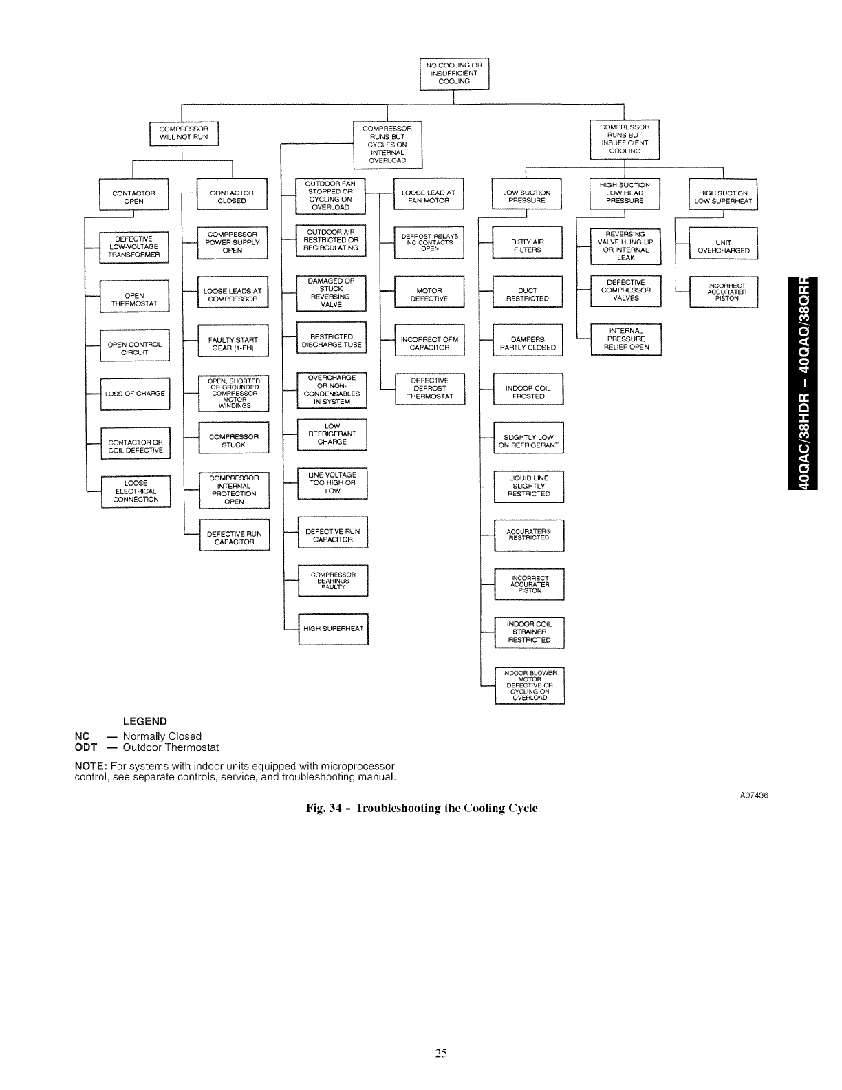
[
I COMPRESSOR i
WILL NOT RUN
I
[ ]
_{ DEFECTIVE
LOW-VOLTAGE
TRANSFORMER
--_ OPENTHERMOSTAT
_{i OPEN CONTROL ]CIRCUIT
_-[ LOSS OF CHARGE ]
_[_ LOOSE
ELECTRICAL
CONNECTION
g COMPRESSOR ]
POWER SUPPLY
OPEN
_ LOOSE LEADS AT ]COMPRESSOR
FAULTY START
GEAR (!-PH)
_[ OPEN, SHORTED,
OR GROUNDED
COMPRESSOR
MOTOR
WINDINGS
q COMPRESSORSTUCK
__ COMPRESSOR
INTERNAL
PROTECTION
OPEN
--_ DEFECTIVE RUN ]CARAC_OR
NO COOLING OR ]
INSUFFICIENT
COOUNG
I
t
COMPRESSOR
RUNS BUT
CYCLES ON
INTERNAL
OVERLOAD
OUTDOOR FAN _L
STOPPED OR
CYCUNGON
OVERLOAD
_[ OUTDOOR AIR 1
RESTRICTED OR
RECIRCULATING
DAMAGED OR
STUCK
REVERSING
VALVE
_{ RESTRICTEDDISCHARGE TUBE
--_ LOOSE LEAD AT IFAN MOTOR
_ DEFROST RELAYS i
NC CONTACTS
OPEN
_[ MOTORDEFECTIVE
_{INOORRECT OFM ]CAPACITOR
£
LOW SUCTION 1PRESSURE
_-[ DIRTY AIR
FILTERS
-_ DUCTRESTRICTED
--_ DAMPERS }
PARTLY CLOSED
l
COMPRESSOR
RUNS BUT
INSUFFICIENT
COOLING
l HIGH SUCTION
LOW HEAD
PRESSURE
__[
__{ REVERSING
VALVE HUNG UP
OR INTERNAL
LEAK
DEFECTIVE
COMPRESSOR
VALVES
1
I HIGHSOCT'ON1LOW SUPERHEAT
__]
[_ UNIT
OVERCHARGED 1
1 iNCORRECT 1
ACCURATER
PISTON
iNTERNAL 1
PRESSURE
RELIEF OPEN
___ OVERCHARGE
OR NON-
CONDENSABLES
IN SYSTEM
LOW
REFRIGERANT
CHARGE
_{_ LINE VOLTAGE
TOO HIGH OR
LOW
__{ DEFECTIVE
DEFPOST
THERMOSTAT
DEFECTIVE RUN t
CAPAC_OR
,_ COMPRESSOR ]
BEARINGS
=¢ULTY
INDOOR COIL ]FROSTED
LIQUID LINE 1
SLIGHTLY
RESTRICTED
ACCURATER®
RESTRICTED
_[ INCORRECT I
ACCURATER
PISTON
__ INDOOR COIL _
STRAINER
RESTRICTED
LEGEND
NC -- Normally Closed
ODT -- Outdoor Thermostat
NOTE: For systems with indoor units equipped with microprocessor
control, see separate controls, service, and troubleshooting manual.
INDOOR BLOWER l
MOTOR
DEFECTIVE OR
CYCLING ON
OVERLOAD
Fig. 34 - Troubleshooting the Cooling Cycle
A07436
25
Copyright 2009 Carrier Corp. • 7310 W. Morris St. • Indianapolis, IN 46231 Printed in U.S.A. Edition Date: 10/09
Manufacturer reserves the right to change, at any time, specification8 and design8 without notice and without obligations,
2d
Catalog No: 40QAC-Q-2SI
Replaces: 40QAC- Q- lSl
