CARRIER Furnace/Heater, Gas Manual L1002455
User Manual: CARRIER CARRIER Furnace/Heater, Gas Manual CARRIER Furnace/Heater, Gas Owner's Manual, CARRIER Furnace/Heater, Gas installation guides
Open the PDF directly: View PDF ![]() .
.
Page Count: 4
Installation Instructions
NOTE: Read the entire instruction manual before starting the
installation.
SAFETY CONSIDERATIONS
Improper installation, adjustment, alteration, service,
maintenance, or use can cause explosion, fire, electrical shock, or
other conditions which may cause death, personal injury, or
property damage. Consult a qualified installer, service agency, or
your distributor or branch for information or assistance. The
qualified installer or agency must use factory-authorized kits or
accessories when modifying this product. Refer to the individual
instructions packaged with the kits or accessories when installing.
Follow all safety codes. Wear safety glasses, protective clothing,
and work gloves. Have a fire extinguisher available. Read these
instructions thoroughly and follow all warnings or cautions
include in literature and attached to the unit. Consult local
building codes, the current editions of the National Fuel Gas
Code (NFGC) NFPA 54/ANSI Z223.1 and the National
Electrical Code (NEC) NFPA 70.
In Canada, refer to the current editions of the National Standards
of Canada CAN/CGA-BI49.1 and .2 Natural Gas and Propane
Installation Codes, and Canadian Electrical Code CSA C22.1
Recognize safety information. This is the safety-alert symbol/_.
When you see this symbol on the unit and in instructions or
manuals, be alert to the potential for personal injury.
Understand the signal words DANGER, WARNING, and
CAUTION. These words are used with the safety-alert symbol.
DANGER identifies the most serious hazards which will result in
severe personal injury or death. WARNING signifies hazards
which could result in personal injury or death. CAUTION is
used to identify unsafe practices which may result in minor
personal injury or product and property damage. NOTE is used
to highlight suggestions which will result in enhanced
installation, reliability, or operation.
FIRE, EXPLOSION, ELECTRICAL SHOCK
HAZARD
Failure to follow this warning could result in personal injury,
death and/or property damage.
Before installing or servicing unit, always turn off main
electrical and gas to unit. Lockout and tag with appropriate
warning label. There may be more than one disconnect
switch.
CUT HAZARD
Failure to follow this caution may result in personal iniury.
Sheet metal parts may have sharp edges or burrs. Use care
and wear appropriate protective clothing, safety glasses and
gloves when handling parts and servicing furnaces.
UNIT DAMAGE HAZARD
Failure to follow this caution may result in improper and
dangerous operation.
Label all wires prior to disconnection when servicing
controls.
INTRODUCTION
This instruction covers installation of the high output permanent
split capacitor (PSC) inducer motor kit on models 340MAV,
340AAV, 345MAV, 350MAV, 350AAV, 351DAS, 353AAV,
490AAV, 58MCA, 58MCB, 58MEB, 58MSA, 58MXA, 58MXB,
PG9MAA and PG9MAB Condensing Gas Furnaces. See Table 1
for kit applicability.
DESCRIPTION AND USAGE
Use this PSC inducer motor kit to replace a failed inducer motor
assembly.
This kit contains the following items:
Inducer assembly 1
Installation Instructions 1
NOTE: Inducer assembly consists of motor and fan, capacitor,
wheel, motor mount, inducer cover, inducer housing, vent cap,
and vent clamp.
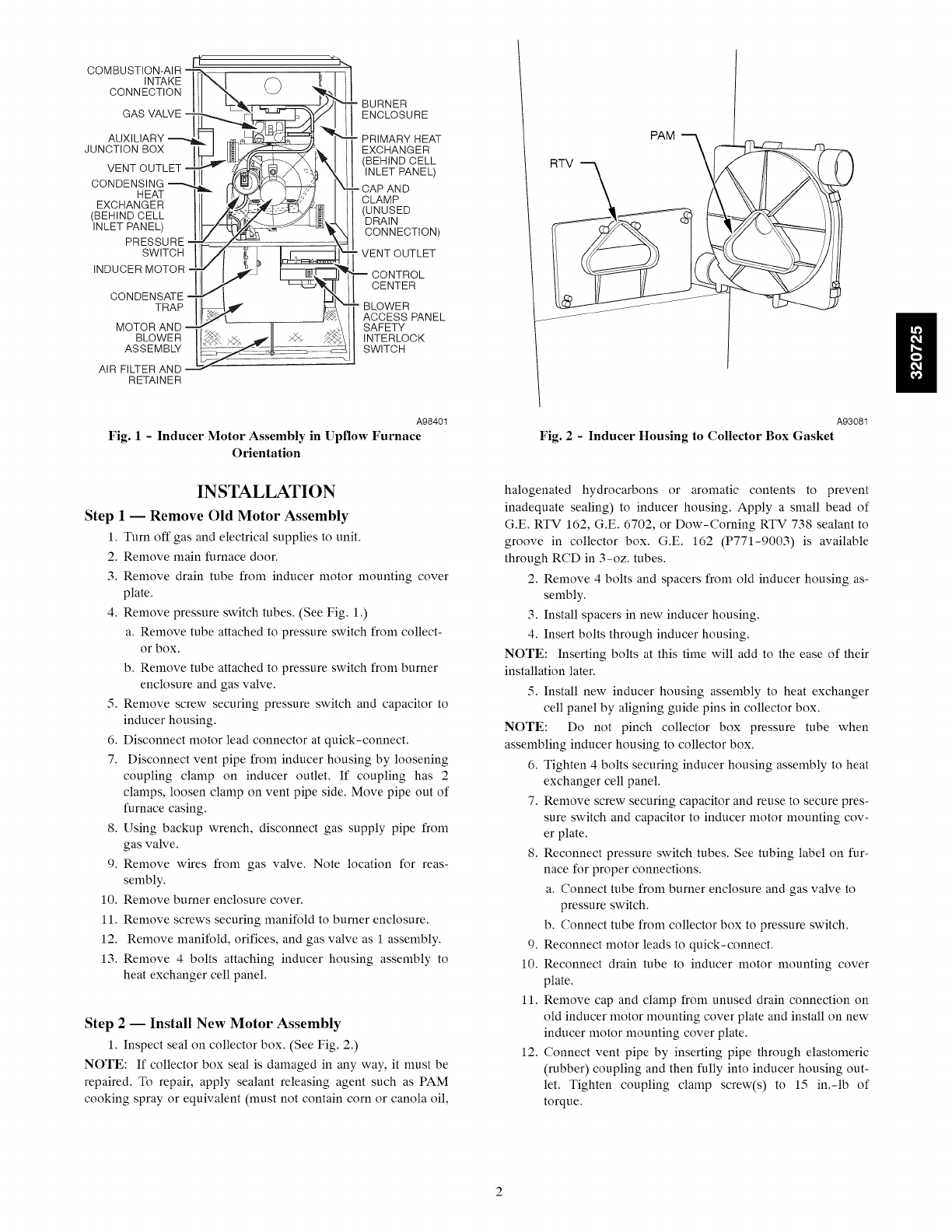
COMBUSTION-AIR -_(
INTAKE
CONNECTION
GAS VALVE -
AUXILIARY
JUNCTION BOX
VENT OUTLET -
CONDENSING
HEAT
EXCHANGER
(BEHIND CELL
INLET PANEL)
PRESSURE -
SWITCH
INDUCER MOTOR
CONDENSATE,
TRAP
MOTOR AND
BLOWER
ASSEMB_
AIR FILTER AND --
RETAINER
BURNER
ENCLOSURE
PRIMARY HEAT
EXCHANGER
(BEHIND CELL
INLET PANEL)
CAP AND
CLAMP
(UNUSED
DRAIN
CONNECTION)
VENT OUTLET
CONTROL
CENTER
BLOWER
ACCESS PANEL
SAFETY
INTERLOCK
SWITCH
A98401
Fig. 1 - Inducer Motor Assembly in Upflow Furnace
Orientation
PAM
RTV
A93081
Fig. 2 -Inducer Housing to Collector Box Gasket
INSTALLATION
Step 1 1Remove Old Motor Assembly
1. Turn off gas and electrical supplies to unit.
2. Remove main furnace door.
3. Remove drain tube from inducer motor mounting cover
plate.
4. Remove pressure switch tubes. (See Fig. 1.)
a. Remove tube attached to pressure switch from collect-
or box.
b. Remove tube attached to pressure switch from burner
enclosure and gas valve.
5. Remove screw securing pressure switch and capacitor to
inducer housing.
6. Disconnect motor lead connector at quick-connect.
7. Disconnect vent pipe from inducer housing by loosening
coupling clamp on inducer outlet. If coupling has 2
clamps, loosen clamp on vent pipe side. Move pipe out of
furnace casing.
8. Using backup wrench, disconnect gas supply pipe from
gas valve.
9. Remove wires from gas valve. Note location for reas-
sembly.
10. Remove burner enclosure cover.
11. Remove screws securing manifold to burner enclosure.
12. Remove manifold, orifices, and gas valve as 1 assembly.
13. Remove 4 bolts attaching inducer housing assembly to
heat exchanger cell panel.
Step 21Install New Motor Assembly
1. Inspect seal on collector box. (See Fig. 2.)
NOTE: If collector box seal is damaged in any way, it must be
repaired. To repair, apply sealant releasing agent such as PAM
cooking spray or equivalent (must not contain corn or canola oil,
halogenated hydrocarbons or aromatic contents to prevent
inadequate sealing) to inducer housing. Apply a small bead of
G.E. RTV 162, G.E. 6702, or Dow-Corning RTV 738 sealant to
groove in collector box. G.E. 162 (P771-9003) is available
through RCD in 3-oz. tubes.
2. Remove 4 bolts and spacers from old inducer housing as-
sembly.
3. Install spacers in new inducer housing.
4. Insert bolts through inducer housing.
NOTE: Inserting bolts at this time will add to the ease of their
installation later.
5. Install new inducer housing assembly to heat exchanger
cell panel by aligning guide pins in collector box.
NOTE: Do not pinch collector box pressure tube when
assembling inducer housing to collector box.
6. Tighten 4 bolts securing inducer housing assembly to heat
exchanger cell panel.
7. Remove screw securing capacitor and reuse to secure pres-
sure switch and capacitor to inducer motor mounting cov-
er plate.
8. Reconnect pressure switch tubes. See tubing label on fur-
nace for proper connections.
a. Connect tube from burner enclosure and gas valve to
pressure switch.
b. Connect tube from collector box to pressure switch.
9. Reconnect motor leads to quick-connect.
10. Reconnect drain tube to inducer motor mounting cover
plate.
11. Remove cap and clamp from unused drain connection on
old inducer motor mounting cover plate and install on new
inducer motor mounting cover plate.
12. Connect vent pipe by inserting pipe through elastomeric
(rubber) coupling and then fully into inducer housing out-
let. Tighten coupling clamp screw(s) to 15 in.-lb of
torque.
CARBON MONOXIDE POISONING
PROPERTY DAMAGE HAZARD
AND
Failure to follow this warning could result in personal
iniury, death and/or property damage.
After completing installation, vent pipe must be installed
and fully seated against inducer housing internal stop.
Coupling clamp screw(s) must be tightened to 15 in.-lb of
torque to prevent disassembly of vent from furnace, and to
prevent vent gas and condensate leakage.
13. Reinstall manifold assembly with gas valve to burner box.
Replace mounting screws.
14. Replace burner box cover.
15. Using a back-up wrench to prevent rotation and improper
orientation, reconnect gas supply pipe to gas valve.
16. Reconnect wires to gas valve. Refer to furnace wiring dia-
gram for proper wire location.
17. Turn on gas and electrical supplies to unit.
18. Check for gas leaks.
FIRE AND EXPLOSION HAZARD
Failure to follow this warning could result in personal
injury, death and/or property damage.
Never check for gas leaks with an open flame. Use a
commercially available soap solution made specifically for
the detection of leaks to check all connections,
19. Check furnace operation through 2 complete cycles.
20. Reinstall main furnace door.
Kit Part Number
320725-756
320725-756
Table 1-Kit Applicability
Fixed Speed Condensing Furnace Inducer Kits
340AAV 58MCA
345MAV 351 DAS 58MSA
340MAV 58MCB
036080
320725-756 048080
060080
320725-756
320725-757
320725-758
024040
036040
024060
036060
048060
036080
048080
060080
048100
060100
060120
060140
350AAV
350MAV
353AAV
024040
036040
024060
036060
048060
036080
048080
060080
048100
060100
060120
060140
024040
036040
024060
036060
048060
036080
048080
060080
048100
060100
060120
060140
040-08
040-12
060-08
060-12
060-16
080-12
080-16
080-20
100-16
100-20
120-20
140-20
58MEB
58MXA
58MXB
040-08
040-12
060-08
060-12
060-16
080-12
080-16
080-20
100-16
100-20
120-20
140-20
040-08
040-12
060-08
060-12
060-16
080-12
080-16
080-20
100-16
100-20
120-20
140-20
PG9MAA
PG9MAB
490AAV
024040
036040
024060
036060
048060
036080
048080
060080
048100
060100
060120
060140
ll
Copyright 2009 CA( _BDP • 7310 W. Morris St. • Iudianapolis, IN 46231 Printed in U.S.A.
Manufacturer reserves the right to change, at any time, specifications and designs without notice and without obligations.
4
Edition Date: 09_09 Catalo_l No: IIK320725-002
Replaces: IIK320725 001. IIK320725 753 001
