CASTLES TECHNOLOGY EZPROX RFID Devices User Manual
CASTLES TECHNOLOGY CO., LTD. RFID Devices Users Manual
UserManual.wiki
>
CASTLES TECHNOLOGY
>
EZPROX User Manual
Users Manual
Navigation menu
Upload a User Manual
Namespaces
Wiki Guide
HTML
PDF
Info
Views
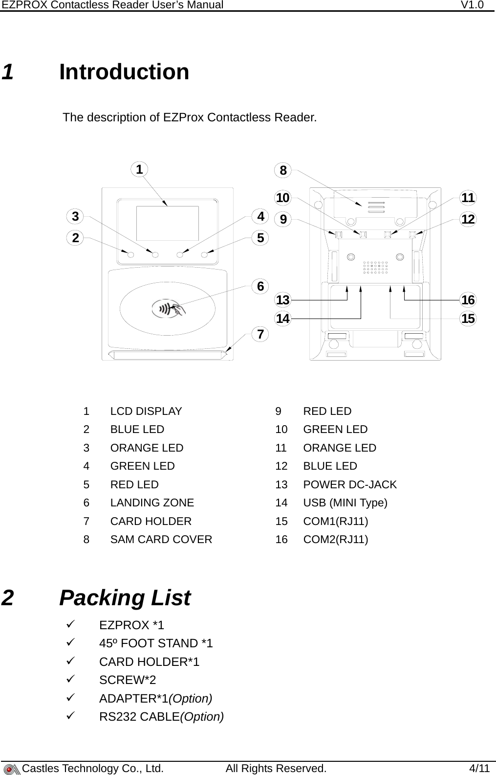
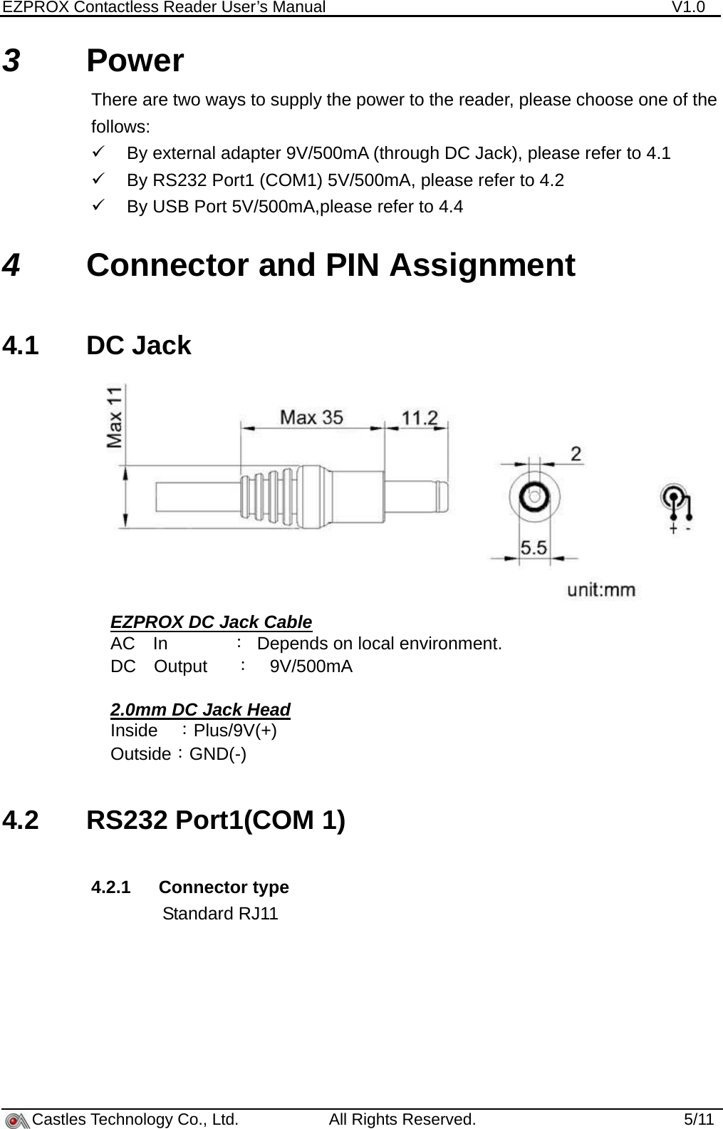
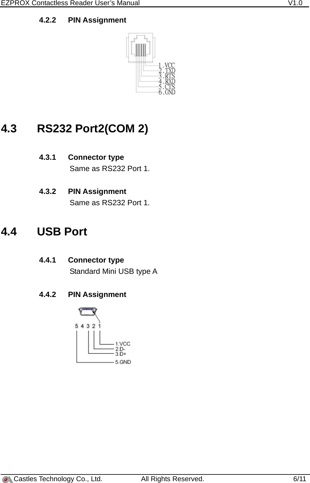
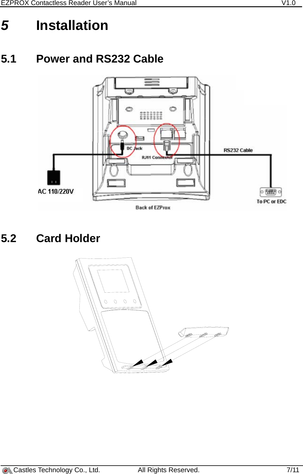
User Manual
Discussion / Help
Navigation