CASTLES TECHNOLOGY EZPROX RFID Devices User Manual
CASTLES TECHNOLOGY CO., LTD. RFID Devices Users Manual
Users Manual

EZProx Contactless Reader
User’s Manual
Version 1.0
August 2006
http://www.castech.com.tw
Doc.# Confidential Level:

EZPROX Contactless Reader User’s Manual V1.0
Castles Technology Co., Ltd. All Rights Reserved. 1/11
Table of Contents
TABLE OF CONTENTS .................................................................................................................................... 1
REVISION HISTORY......................................................................................................................................... 2
WARNING ......................................................................................................................................................... 3
ABOUT THIS MANUAL .................................................................................................................................... 3
1 INTRODUCTION....................................................................................................................................... 4
2 PACKING LIST......................................................................................................................................... 4
3 POWER..................................................................................................................................................... 5
4 CONNECTOR AND PIN ASSIGNMENT .................................................................................................. 5
4.1 DC JACK............................................................................................................................................ 5
4.2 RS232 PORT1(COM 1)...................................................................................................................... 5
4.2.1 Connector type............................................................................................................................. 5
4.2.2 PIN Assignment ........................................................................................................................... 6
4.3 RS232 PORT2(COM 2)...................................................................................................................... 6
4.3.1 Connector type............................................................................................................................. 6
4.3.2 PIN Assignment ........................................................................................................................... 6
4.4 USB PORT......................................................................................................................................... 6
4.4.1 Connector type............................................................................................................................. 6
4.4.2 PIN Assignment ........................................................................................................................... 6
5 INSTALLATION ........................................................................................................................................ 7
5.1 POWER AND RS232 CABLE................................................................................................................. 7
5.2 CARD HOLDER ................................................................................................................................... 7
5.3 45º FOOT STAND ................................................................................................................................8
5.4 SAM INSERTION ................................................................................................................................. 9
5.5 PLACEMENT NOTICE ......................................................................................................................... 10
6 LED INDICATOR .................................................................................................................................... 10
6.1 FRONT SIDE...................................................................................................................................... 10
6.2 REAR SIDE ........................................................................................................................................11
6.3 LED’S REPRESENTATION STATES .......................................................................................................11
7 CONTACTLESS CARD LANDING ZONE ..............................................................................................11

EZPROX Contactless Reader User’s Manual V1.0
Castles Technology Co., Ltd. All Rights Reserved. 2/11
Revision History
Version Date Editor Description
V1.0 2006.08.01 Mindy Created

EZPROX Contactless Reader User’s Manual V1.0
Castles Technology Co., Ltd. All Rights Reserved. 3/11
WARNING
Information in this document is subject to change without prior notice.
No part of this publication may be reproduced, transmitted, stored in a retrieval system, nor
translated into any human or computer language, in any form or by any means, electronic,
mechanical, magnetic, optical, chemical, manual, or otherwise, without the prior written
permission of Castles Technology Co., Ltd.
All trademarks mentioned are proprietary of their respective owners.
FCC Compliance Statement:
This device complies with Part 15 of the FCC Rules. Operation is subject to the following two
conditions: (1) This device may not cause harmful interference, and (2) This device must accept any
interference received, including interference that may cause undesired operation.
Note: The manufacturer is not responsible for any radio or TV interference caused by unauthorized
modifications to this equipment. Such modifications could void the user’s authority to operate the
equipment.
ABOUT THIS MANUAL
EZPROX Contactless Reader User’s Manual V1.0
Castles Technology Co., Ltd. All Rights Reserved. 4/11
1 Introduction
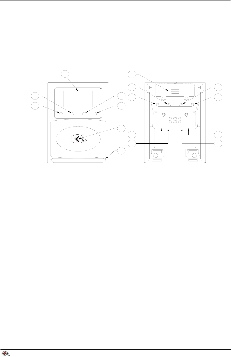
The description of EZProx Contactless Reader.
7
8
10
4
5
6
1
2
312
9
11
13
15
16
14
1 LCD DISPLAY 9 RED LED
2 BLUE LED 10 GREEN LED
3 ORANGE LED 11 ORANGE LED
4 GREEN LED 12 BLUE LED
5 RED LED 13 POWER DC-JACK
6 LANDING ZONE 14 USB (MINI Type)
7 CARD HOLDER 15 COM1(RJ11)
8 SAM CARD COVER 16 COM2(RJ11)
2 Packing List
9 EZPROX *1
9 45º FOOT STAND *1
9 CARD HOLDER*1
9 SCREW*2
9 ADAPTER*1(Option)
9 RS232 CABLE(Option)
EZPROX Contactless Reader User’s Manual V1.0
Castles Technology Co., Ltd. All Rights Reserved. 5/11
3 Power
There are two ways to supply the power to the reader, please choose one of the
follows:
9 By external adapter 9V/500mA (through DC Jack), please refer to 4.1
9 By RS232 Port1 (COM1) 5V/500mA, please refer to 4.2
9 By USB Port 5V/500mA,please refer to 4.4
4 Connector and PIN Assignment
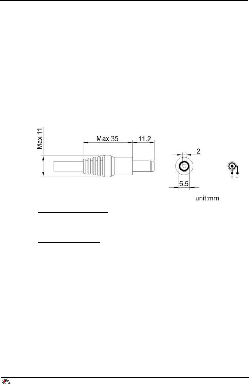
4.1 DC Jack
EZPROX DC Jack Cable
AC In : Depends on local environment.
DC Output : 9V/500mA
2.0mm DC Jack Head
Inside :Plus/9V(+)
Outside:GND(-)
4.2 RS232 Port1(COM 1)
4.2.1 Connector type
Standard RJ11
EZPROX Contactless Reader User’s Manual V1.0
Castles Technology Co., Ltd. All Rights Reserved. 6/11
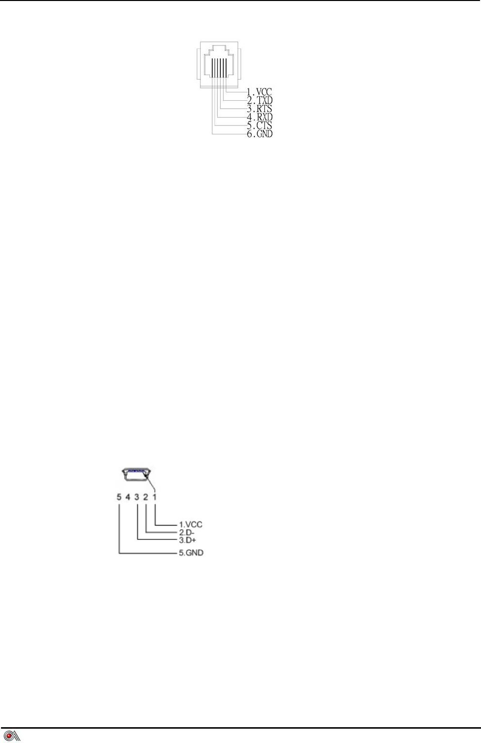
4.2.2 PIN Assignment
4.3 RS232 Port2(COM 2)
4.3.1 Connector type
Same as RS232 Port 1.
4.3.2 PIN Assignment
Same as RS232 Port 1.
4.4 USB Port
4.4.1 Connector type
Standard Mini USB type A
4.4.2 PIN Assignment
EZPROX Contactless Reader User’s Manual V1.0
Castles Technology Co., Ltd. All Rights Reserved. 7/11
5 Installation
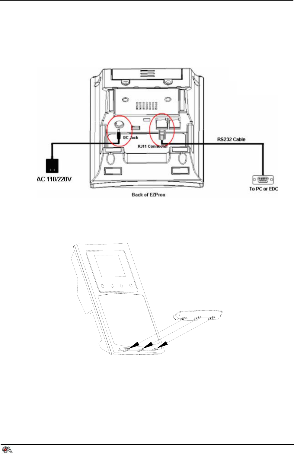
5.1 Power and RS232 Cable
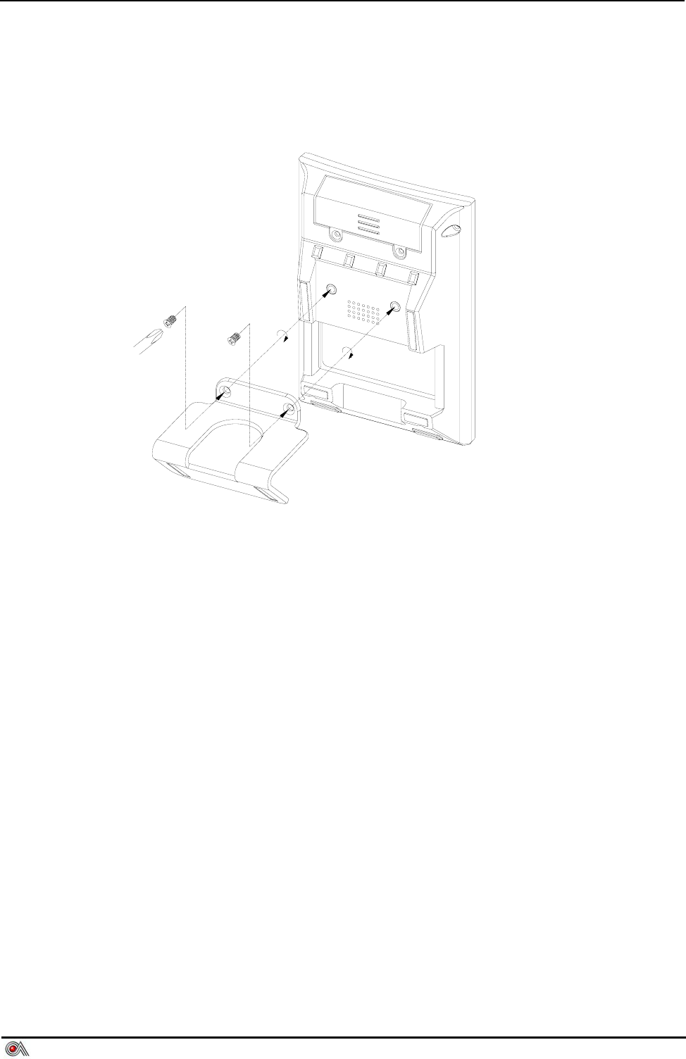
5.2 Card Holder
EZPROX Contactless Reader User’s Manual V1.0
Castles Technology Co., Ltd. All Rights Reserved. 8/11
5.3 45º Foot Stand
User can direct put Ezprox on desk with 8º angle or install this stand to make
EZPROX stand with 45º angle.
EZPROX Contactless Reader User’s Manual V1.0
Castles Technology Co., Ltd. All Rights Reserved. 9/11
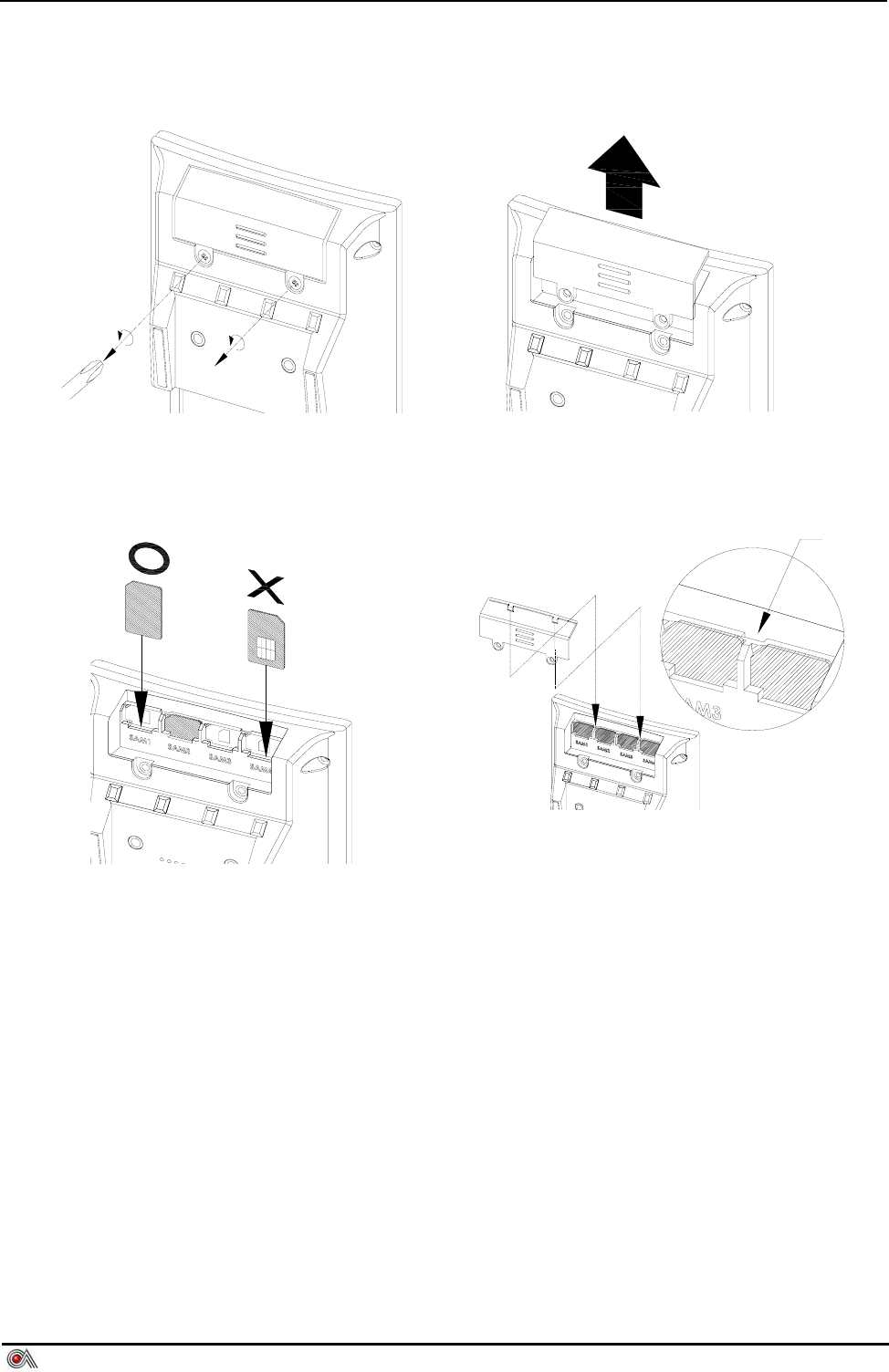
5.4 SAM Insertion
Step 1. Unscrew SAM Cover Step 2. Open SAM Cover
Step 3. Insert SAM Card Step 4. Close SAM Cover
EZPROX Contactless Reader User’s Manual V1.0
Castles Technology Co., Ltd. All Rights Reserved. 10/11
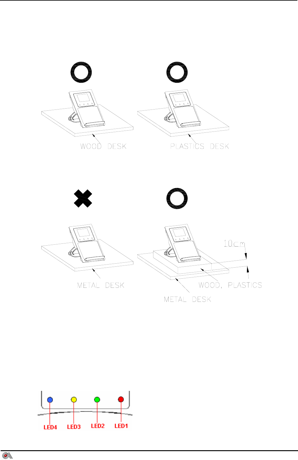
5.5 Placement Notice
6 LED Indicator
6.1 Front side
4 LEDs in front side.
EZPROX Contactless Reader User’s Manual V1.0
Castles Technology Co., Ltd. All Rights Reserved. 11/11
6.2 Rear side
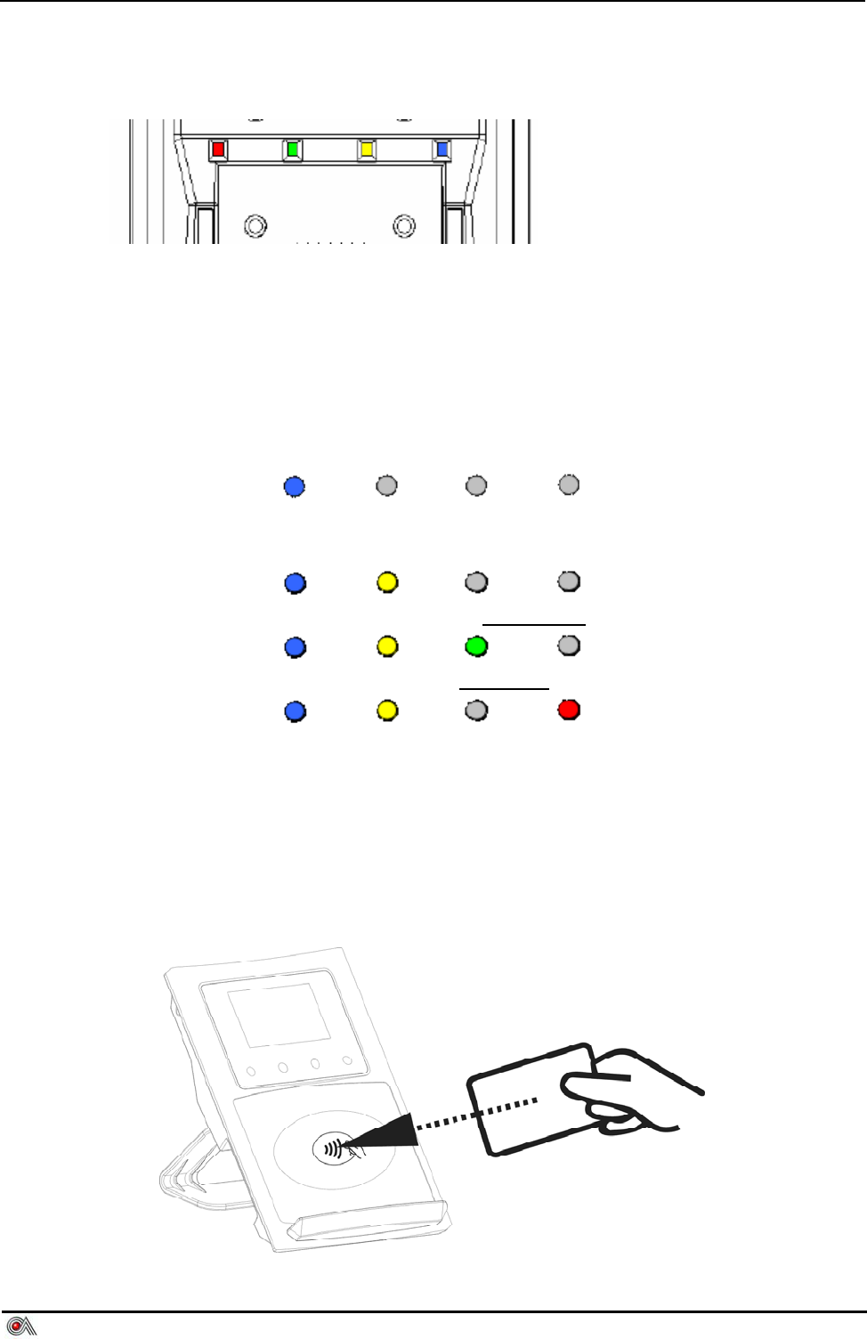
4 LEDs in rear side.
6.3 LED’s Representation States
The state of the LED indicators described as follows:
z After EZPROX initialization and ready for transaction, the blue LED
indicates terminal is ready to conduct a Contactless card ( PayPass ,
VisaWave , JCB or others ) ? transaction.
z Blue and yellow indicates that a card or device has been detected and the
processing has started
z Blue, yellow and green indicates a SUCCESS reading status.
z Blue, yellow and red indicates a FAILURE reading status.
All of the four different coloured LEDs should not light up at the same time.
7 Contactless Card Landing Zone
The icon of Land Zone has printed on the center of working area, which indicate
that where is the correct location to approach user’s card