CASTLES TECHNOLOGY UPT1000 POS Terminal User Manual
CASTLES TECHNOLOGY CO., LTD. POS Terminal Users Manual
UserManual.wiki
>
CASTLES TECHNOLOGY
>
UPT1000 User Manual
Users Manual
Navigation menu
Upload a User Manual
Namespaces
Wiki Guide
HTML
PDF
Info
Views
User Manual
Discussion / Help
Navigation
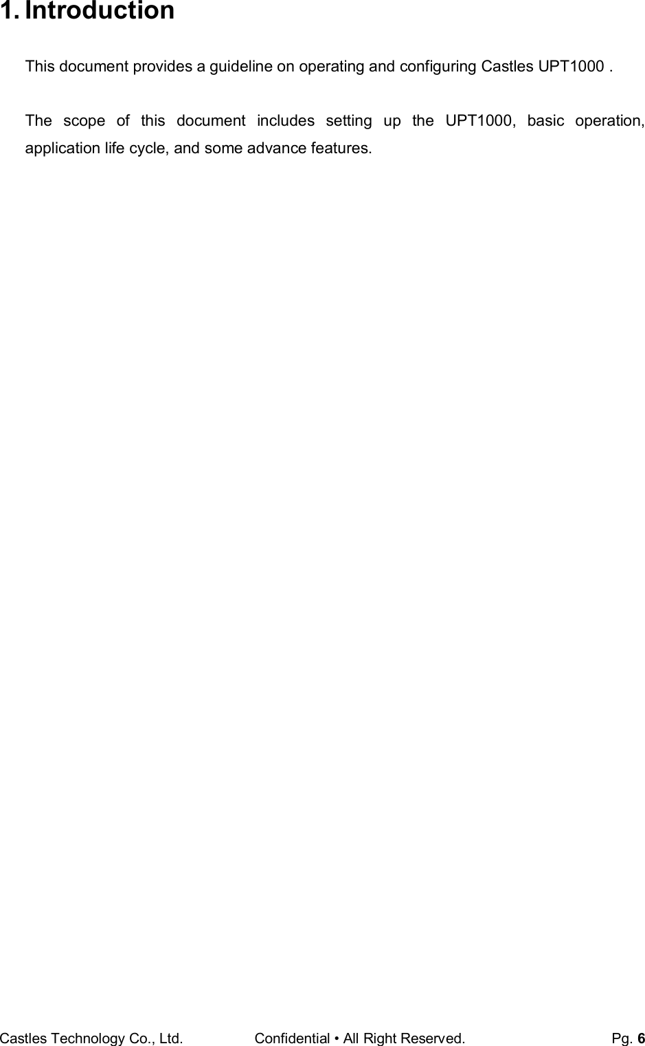
![Castles Technology Co., Ltd. Confidential • All Right Reserved. Pg. 9 3. Basic Operation 3.1. Program Manager Once the power is on in normal status, UPT1000 will enter Program Manager if no default application selected. All user applications are listed in Program Manager. Users can select an application and run the application, view the application info, delete the application, or set application to the default one to run once the power is on. Users may enter System Menu to configure UPT1000 settings. Program Manager Press[0] button to enter System Menu. Press [1] button to toggle default application selection. Press [2] button to delete application. Press [3] button to view application info. Press [OK] button to run application. Press [ ↑ ] or [↓] as the up and down buttonto select application. System Menu Page 1 Press [↓] button to page 2. Program Manager -----------01/02 1.App1 2.App2 0:Download System Menu 1.Download AP 2.System Info 3.Memory Status 4.Sys Settings 5.Test Utility 6.Factory Reset 7.Power Off](https://usermanual.wiki/CASTLES-TECHNOLOGY/UPT1000/User-Guide-3285958-Page-9.png)
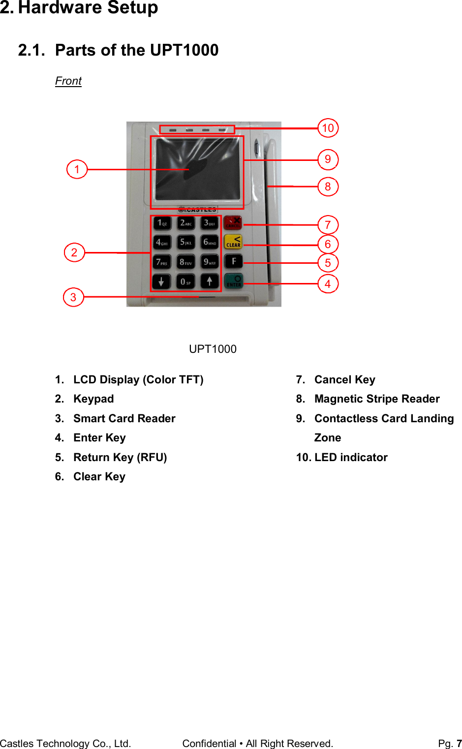
![Castles Technology Co., Ltd. Confidential • All Right Reserved. Pg. 10 Page 2 Press [↑] button to page1. Press [↓] button to page3. Page 3 Press [↑] button to page2. 3.2. Download AP Download user application or kernel modules firmware. System Menu Press [1] button to enter Download AP menu. Download AP Menu System Menu 1.FK PWD Change 2.Share obj Mng 3.Embedded TMS 4.Font Mng 5.Debug Tools 6.ULD KEY HASH 7.HW Detect System Menu 1.Download AP 2.System Info 3.Memory Status 4.Sys Settings 5.Test Utility 6.Factory Reset 7.Power Off System Menu 1.BluetoothSetup 2.Plug-in Mng 3.Key Injection](https://usermanual.wiki/CASTLES-TECHNOLOGY/UPT1000/User-Guide-3285958-Page-10.png)
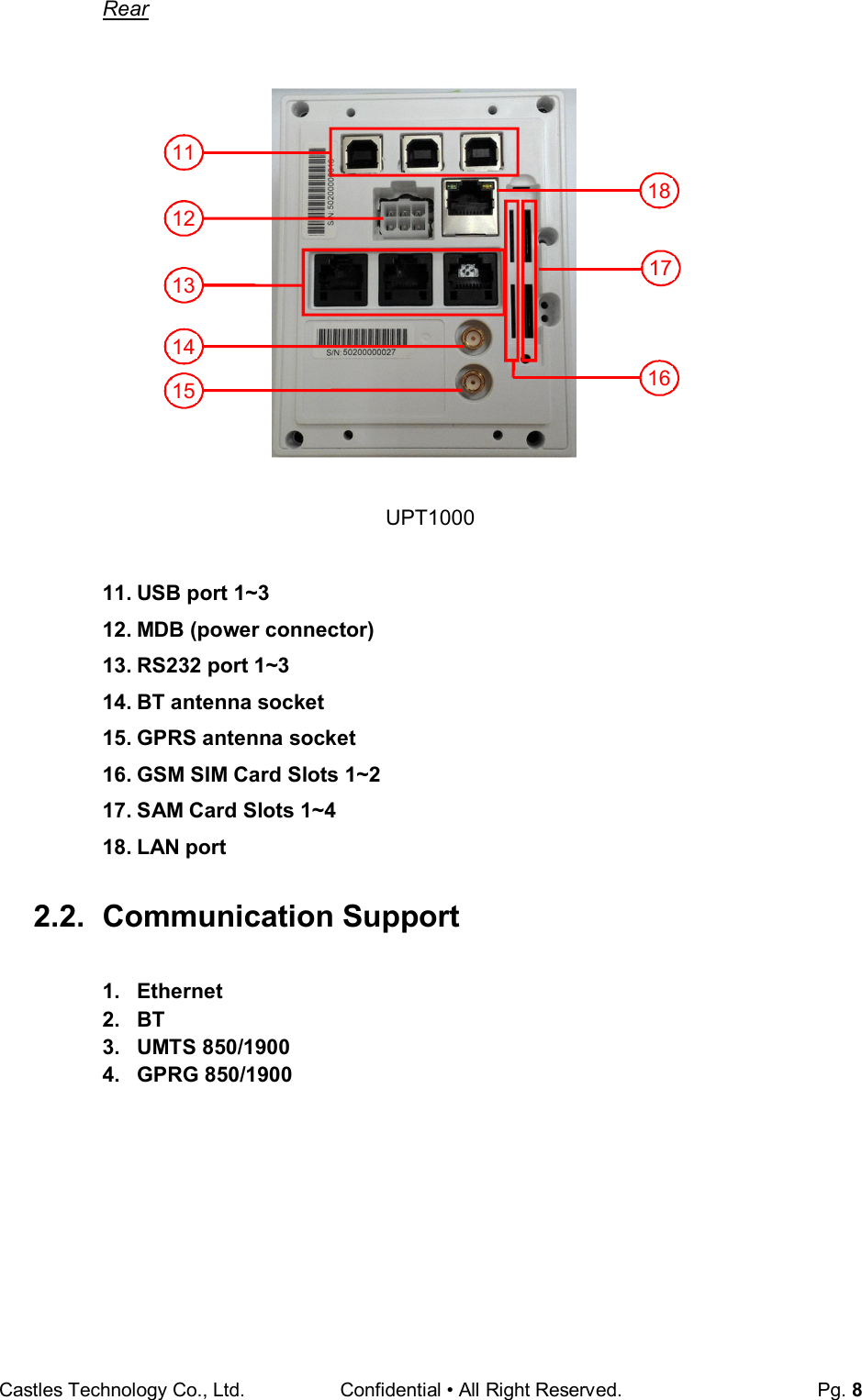
![Castles Technology Co., Ltd. Confidential • All Right Reserved. Pg. 11 Select download source: Press [1] button to select source as RS232 or USB connection and enter ULD download mode. Press [2] button to select source as USB disk. Press [3] button to select source as SD card. (Not support) 3.3. System Info View kernel module firmware information. System Menu Press [2] button to enter System Info menu. System Info Menu Page 1 Page 2 Page 3 Press [↓] button to next page. Download EX 1.RS232 or USB 2.USB Disk 3.SD Card Select DW Source System Menu 1.Download AP 2.System Info 3.Memory Status 4.Sys Settings 5.Test Utility 6.Factory Reset 7.Power Off SYSTEM INFO ---Kernel Ver--- BIOS :VR0024 SULD :VRF010 LINUXKNL:VR0024 ROOTFS :VR0010 SYSTEM INFO --- KOVer --- SECURITY :VR0025 KMS :VR0027 DRV :VR0046 USB :N/A CIF :VR0025 SAM :VR0034 SYSTEM INFO --- KOVer2 --- CL :VR0018 SC :VR0011](https://usermanual.wiki/CASTLES-TECHNOLOGY/UPT1000/User-Guide-3285958-Page-11.png)
![Castles Technology Co., Ltd. Confidential • All Right Reserved. Pg. 12 Page 4 Page 5 Page 6 Page 8 Page 9 Page 10 3.4. Memory Status View flash memory and RAM information. System Menu Press [3] button to enter Memory Status menu. Memory Status Menu SYSTEM INFO --- SO Ver3 --- GSM :VR0029 BARCODE :VR0013 TLS :VR0014 CLVW :VR0024 CTOSAPI :VR0039 SYSTEM INFO --- HWMVer --- CRDL/ETHE:ONCHIP CLM-MP : N/A --- APVer --- ULDPM :VR0036 SYSTEM INFO HUSBID:0CA6A050 CUSBID:N/A --Factory S/N--- FFFFFFFFFFFFFFFF SYSTEM INFO ----- SOVer----- UART :VR0017 USBH :VR0011 MODEM :VR0019 ETHERNET :VR0035 FONT :VR0032 LCD :VR0042 SYSTEM INFO ---- SO Ver2 --- PRT :VR0025 RTC :VR0013 ULDPM :VR0029 PPPMODEM :VR0031 KMS :VR0032 FS :VR0016 SYSTEM INFO --EXT SO Ver P.1-- CACLMDL :VR0008 CACLENTRY :VR0008 CAMPP :VR0007 CAVPW :VR0019 CAAEP :VR0004 CAJCT :VR0007 System Menu 1.Download AP 2.System Info 3.Memory Status 4.Sys Settings 5.Test Utility 6.Factory Reset 7.Power Off MEMORY STATUS --FLASH Memory-- Total: 130688KB Used : 44644KB --SDRAM Memory-- Total: 65408KB Used : 32384KB](https://usermanual.wiki/CASTLES-TECHNOLOGY/UPT1000/User-Guide-3285958-Page-12.png)
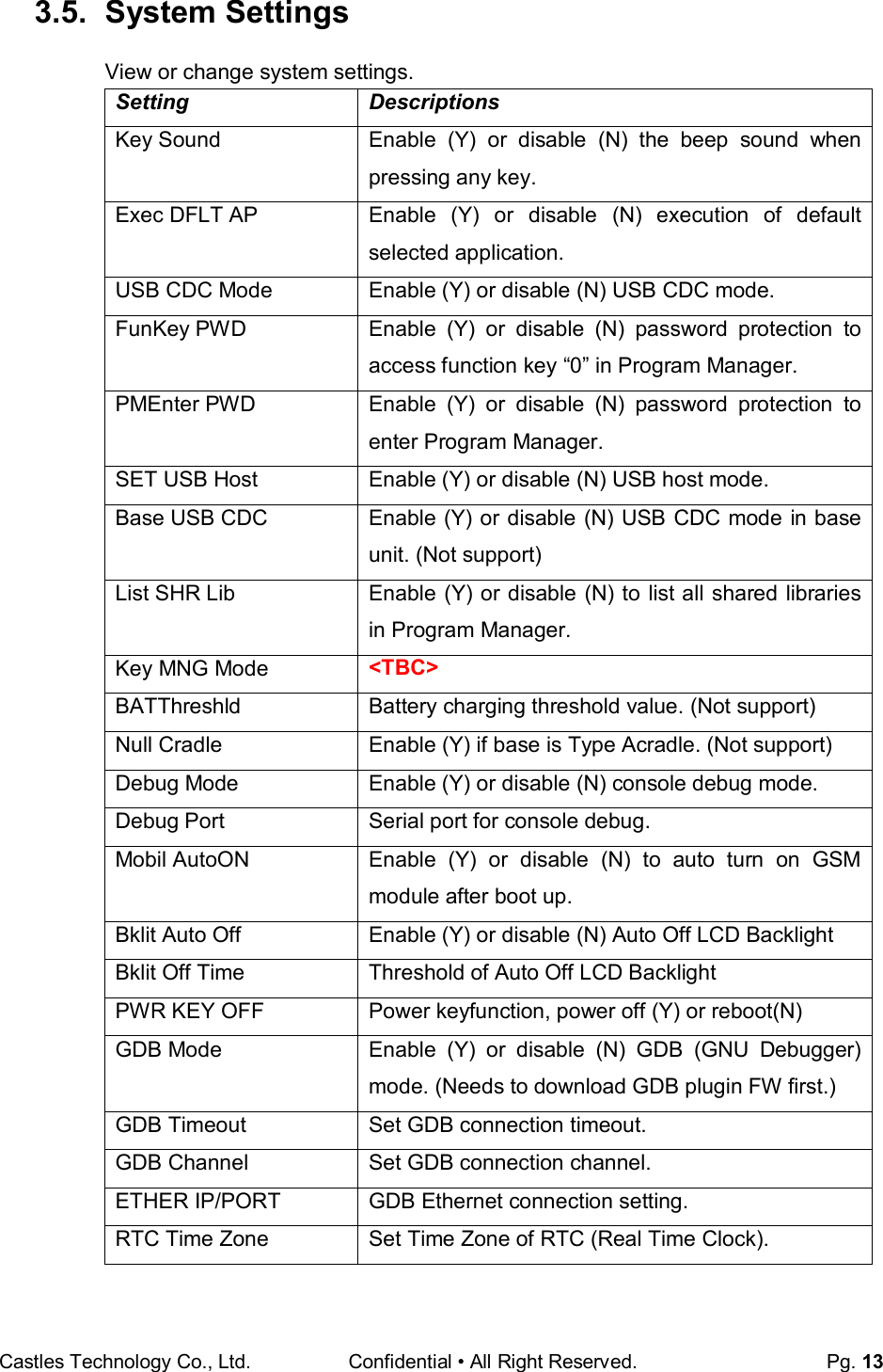
![Castles Technology Co., Ltd. Confidential • All Right Reserved. Pg. 14 NTP Enable Enable (Y) or disable (N) NTP (Network Time Protocol) function. NTP Update Freq Frequency of Network Time Protocol updating. Halt Timeout Set timeout of AP to get back to Program Manager whenever AP is in halt state. PWM Auto Enable (Y) or disable (N) power saving mode. PWM Mode Select (STB) standby mode or (SLP) sleep mode for power saving mode. PWM Time Set time period to make machine enter power saving mode from idle state. BAT PROTECT MODE Set battery protect mode. (Not support) System Menu Press [4] button to enter System Settings menu. System Settings Menu Page 1 Page 2 Page 3 Page 4 System Menu 1.Download AP 2.System Info 3.Memory Status 4.Sys Settings 5.Test Utility 6.Factory Reset 7.Power Off SYS SETTINGS Key Sound : Y Exec DFLT AP : Y -Default AP Name USB CDC Mode : Y FunKey PWD : N PMEnter PWD : N 2: Next Page SYS SETTINGS SET USB Host : N Base USB CDC : X List SHR Lib : N Key MNG Mode : 0 Bat Threshld : X Null Cradle : X 1: Prev 2: Next SYS SETTINGS Debug Mode : N Debug Port : X Mobil AutoON : N Bklit Auto Off : N BklitOff Time : X PWR KEY OFF : N 1: Prev 2: Next SYS SETTINGS GDB Mode : GMT GDB Timeout : N GDB Channel : X ETHER IP/PORT 1: Prev 2: Next](https://usermanual.wiki/CASTLES-TECHNOLOGY/UPT1000/User-Guide-3285958-Page-14.png)
![Castles Technology Co., Ltd. Confidential • All Right Reserved. Pg. 15 Page 5 Page 6 Press [↑] or [↓]button to select setting. Press [OK] button to change the setting value. Press [˂ ] button to toggle Y N Y. Press [1] button to previous page. Press [2] button to next page. SYS SETTINGS RTC Time Zone : GMT NTP Enable : N NTP Update Freq : X 1: Prev 2: Next SYS SETTINGS Halt Timeout : 0 PWM Auto : X PWM Mode : X PWM Time : X BAT PROTECT MODE : X 1: Prev Page](https://usermanual.wiki/CASTLES-TECHNOLOGY/UPT1000/User-Guide-3285958-Page-15.png)
![Castles Technology Co., Ltd. Confidential • All Right Reserved. Pg. 16 3.6. Test Utility Perform hardware components diagnosis. System Menu Press [5] button to enter Test Utility menu. Test Utility Menu Page 1 Press [1] and [OK] to diagnose LCD. Press [2] and [OK] to diagnose keyboard. Press [3] and [OK] to diagnose flash memory. Press [4] and [OK] to diagnose smart card module. Press [5] and [OK] to diagnose backlight. Press [6] and [OK] to diagnose magnetic stripe card reader. Press [↓] button to page 2. System Menu 1.Download AP 2.System Info 3.Memory Status 4.Sys Settings 5.Test Utility 6.Factory Reset 7.Power Off Main Menu 9123 1.LCD 2.Keyboard 3.Flash 4.Smart Card 5.Backlight 6.MSR -> 1/3](https://usermanual.wiki/CASTLES-TECHNOLOGY/UPT1000/User-Guide-3285958-Page-16.png)
![Castles Technology Co., Ltd. Confidential • All Right Reserved. Pg. 17 Page 2 Press [7] and [OK] to diagnose LED. Press [8] and [OK] to diagnose RTC. Press [9] and [OK] to check Printer. Press [10] and [OK] to check FONT file in UPT1000. Press [11] and [OK] to check CL transparent. Press [12] and [OK] to test Cantactless Card. Press [↑] button to page 1. Press [↓] button to page 3. Page 3 Press [13] and [OK] to execute SD Card Test. (Not support) Press [14] and [OK] to testfunctionality ofWiFi. Press [15] and [OK] to test functionality of power saving. Press [16] and [OK] to test functionality of multiple communication ways. Press [17] and [OK] to testfunctionality of Bluetooth. Press [↑] button to page2. Main Menu 9123 13.SD Card Test 14.Wi-Fi Test 15.Power Saving 16.Comm Menu 17.BT Test -> 3/3 Main Menu 9123 7.LED 8.RTC 9.Printer 10.Font 11.CL Transparent 12.CL Card Test -> 2/3](https://usermanual.wiki/CASTLES-TECHNOLOGY/UPT1000/User-Guide-3285958-Page-17.png)
![Castles Technology Co., Ltd. Confidential • All Right Reserved. Pg. 18 3.7. Factory Reset Perform factory reset, all user application, fonts and data will be deleted. System Menu Press [6] button to enter Factory Reset menu. Press [OK]. Enter password and press [OK]. Enter factory reset password.(Default password: 8418) System Menu 1.Download AP 2.System Info 3.Memory Status 4.Sys Settings 5.Test Utility 6.Factory Reset 7.Power Off FacRest Password Enter Password: **** FacRest Password OK to reset?](https://usermanual.wiki/CASTLES-TECHNOLOGY/UPT1000/User-Guide-3285958-Page-18.png)
![Castles Technology Co., Ltd. Confidential • All Right Reserved. Pg. 19 Start erasing, and then go back to Program Manager. 3.8. Power Off Power off the machine. System Menu Press [7] button to power off the machine. System Menu 1.Download AP 2.System Info 3.Memory Status 4.Sys Settings 5.Test Utility 6.Factory Reset 7.Power Off FacRestPassword Enter Password: **** Erasing…](https://usermanual.wiki/CASTLES-TECHNOLOGY/UPT1000/User-Guide-3285958-Page-19.png)
![Castles Technology Co., Ltd. Confidential • All Right Reserved. Pg. 20 3.9. FK PWD Change Change the keyin password. System Menu (Page 2) Press [1] button to enter Password Manager Menu. Enter current password. (Default password is "0000") Enter new password. Enter new password again to confirm. User must have to change the Default key to user own key at the first time. The Default Key Value in Password Manager is as below: Function Key 0000 PMEnter Key 0000 Factory Key 8418 FunKey Password Enter Password: **** FunKey Password New Password: **** Confirm Password **** PWD Changed OK System Menu 1.FK PWD Change 2.Share obj Mng 3.Embedded TMS 4.Font Mng 5.Debug Tools 6.ULD KEY HASH 7.HW Detect](https://usermanual.wiki/CASTLES-TECHNOLOGY/UPT1000/User-Guide-3285958-Page-20.png)
![Castles Technology Co., Ltd. Confidential • All Right Reserved. Pg. 21 3.10. Share Object Management View share object in machine . System Menu (Page 2) Press [2] button to enter Share Object Management menu. Share Object Management Menu Press [1] button to view shared libraries. Press [2] button to view shared files. Share objMng 1.Share LIB 2.Share File System Menu 1.FK PWD Change 2.Share obj Mng 3.Embedded TMS 4.Font Mng 5.Debug Tools 6.ULD KEY HASH 7.HW Detect](https://usermanual.wiki/CASTLES-TECHNOLOGY/UPT1000/User-Guide-3285958-Page-21.png)
![Castles Technology Co., Ltd. Confidential • All Right Reserved. Pg. 22 3.11. Embedded TMS TMS (Terminal Managerment System) setting menu. System Menu (Page 2) Press [3] button to enter TMS setting menu. CASTLES TMS Press [1] button to connect server. Press [2] button to enter system config menu. Press [3] button to reset config. Press [4] button to set compatible config. CASTLES TMS 1.Connect Server 2.System Config 3.Reset Config 4.CompatibleConfig System Menu 1.FK PWD Change 2.Share obj Mng 3.Embedded TMS 4.Font Mng 5.Debug Tools 6.ULD KEY HASH 7.HW Detect](https://usermanual.wiki/CASTLES-TECHNOLOGY/UPT1000/User-Guide-3285958-Page-22.png)
![Castles Technology Co., Ltd. Confidential • All Right Reserved. Pg. 23 3.12. Font Mng View Font Management. System Menu (Page 2) Press [4] button to view Font Management. FontManagment Press [1] button to view FNT Font list. Press [2] button to view TTF Font list. Font Mng 1.FNT File 2.TTF File System Menu 1.FK PWD Change 2.Share obj Mng 3.Embedded TMS 4.Font Mng 5.Debug Tools 6.ULD KEY HASH 7.HW Detect](https://usermanual.wiki/CASTLES-TECHNOLOGY/UPT1000/User-Guide-3285958-Page-23.png)
![Castles Technology Co., Ltd. Confidential • All Right Reserved. Pg. 24 3.13. Debug Tools Get core dump or debug log. System Menu (Page 2) Press [5] button to enter Debug Tools menu. Debug Tools Press [1] button to enter core dump menu. Press [2] button to enter debug log menu. Debug Tools 1.Core Dump 2.Debug Log System Menu 1.FK PWD Change 2.Share obj Mng 3.Embedded TMS 4.Font Mng 5.Debug Tools 6.ULD KEY HASH 7.HW Detect](https://usermanual.wiki/CASTLES-TECHNOLOGY/UPT1000/User-Guide-3285958-Page-24.png)
![Castles Technology Co., Ltd. Confidential • All Right Reserved. Pg. 25 3.14. ULD Key Hash View ULD user key hash value. System Menu (Page 2) Press [6] button to view hash value. USER ENV KEY DA9C91FE668DF4B6D637CDBCCEC201444AA2C7FF USER SIGN KEY D52F36A1B569B5ABBA4FEAEFB34BEC000101D58C System Menu 1.FK PWD Change 2.Share obj Mng 3.Embedded TMS 4.Font Mng 5.Debug Tools 6.ULD KEY HASH 7.HW Detect](https://usermanual.wiki/CASTLES-TECHNOLOGY/UPT1000/User-Guide-3285958-Page-25.png)
![Castles Technology Co., Ltd. Confidential • All Right Reserved. Pg. 26 3.15. HW Detect Run hardware detection. System Menu (Page 2) Press [7] button to run HW detection. Press any key to reboot system. HW TYPE Original HW-TYPE : EGCB New HW-TYPE : EGCB Please Any Key. System Menu 1.FK PWD Change 2.Share obj Mng 3.Embedded TMS 4.Font Mng 5.Debug Tools 6.ULD KEY HASH 7.HW Detect](https://usermanual.wiki/CASTLES-TECHNOLOGY/UPT1000/User-Guide-3285958-Page-26.png)
![Castles Technology Co., Ltd. Confidential • All Right Reserved. Pg. 27 3.16. Bluetooth Setup Setup Bluetooth config. System Menu (Page 2) Press [1] button to enter Bluetooth setting menu. Bluetooth Setup Press [1] button to enter Handset BT Setup menu. Press [2] button to enter Cradle CH Setup menu. System Menu 1.Bluetooth Setup 2.Plug-in Mng 3.Key Injection Bluetooth Setup 1.Handset BT Setup 2.Cradle CH Setup](https://usermanual.wiki/CASTLES-TECHNOLOGY/UPT1000/User-Guide-3285958-Page-27.png)
![Castles Technology Co., Ltd. Confidential • All Right Reserved. Pg. 28 3.17. Plug-in Mng View Plug-in Management. System Menu (Page 2) Press [2] button to view Plug-in Management. Press [↑] or [↓] button to select item. Press [1] button to get item information. Press [2] button to delete item. Plug-in Mng 1.Bluetooth :V9116 1.Info 2.Del System Menu 1.Bluetooth Setup 2.Plug-in Mng 3.Key Injection 4.TP Calibration System Menu 1.Bluetooth Setup 2.Plug-in Mng 3.Key Injection](https://usermanual.wiki/CASTLES-TECHNOLOGY/UPT1000/User-Guide-3285958-Page-28.png)
![Castles Technology Co., Ltd. Confidential • All Right Reserved. Pg. 29 3.18. Key Injection Key Injection function. (Factory use only.) System Menu (Page 3) Press [3] button to view Key Injection. Key Injection Waiting for Command System Menu 1.Bluetooth Setup 2.Plug-in Mng 3.Key Injection](https://usermanual.wiki/CASTLES-TECHNOLOGY/UPT1000/User-Guide-3285958-Page-29.png)
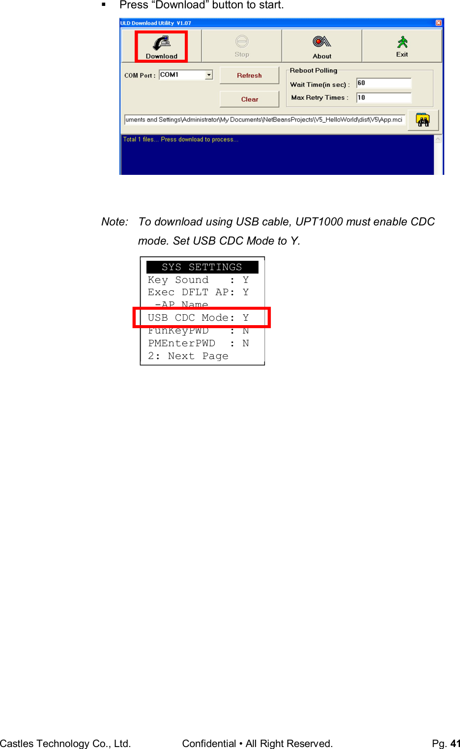
![Castles Technology Co., Ltd. Confidential • All Right Reserved. Pg. 40 Select COM port Browse and select mci file or mmci file Setup UPT1000 to enter download mode Press [0] button in Program Manager (PM) Press [1] button to select “1. Download AP“ Press [1] button again to select download via RS232 or USB](https://usermanual.wiki/CASTLES-TECHNOLOGY/UPT1000/User-Guide-3285958-Page-40.png)
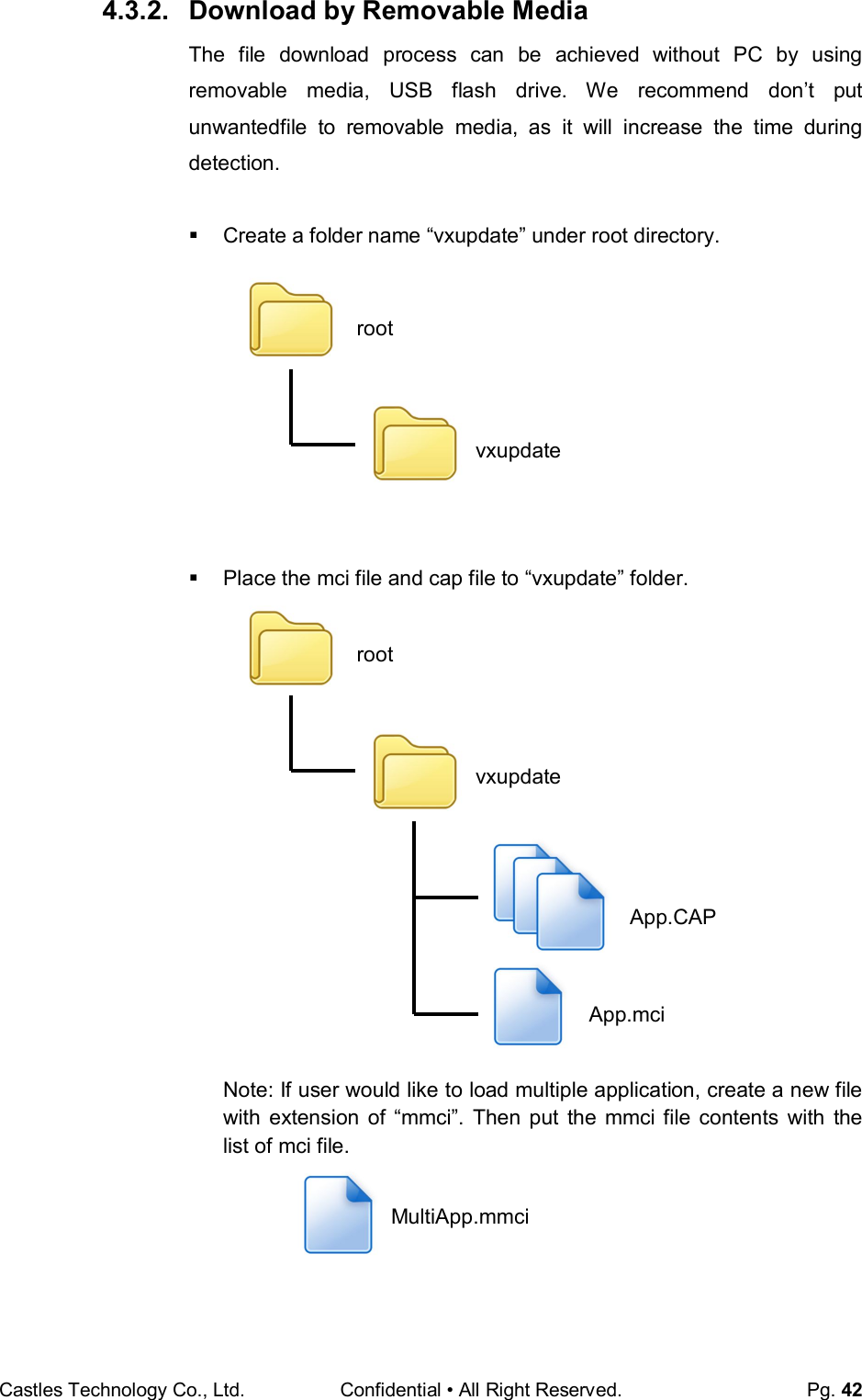
![Castles Technology Co., Ltd. Confidential • All Right Reserved. Pg. 43 Insert removable media to UPT1000, and select the removable media type in “Download AP” menu. Download AP Menu o Press [2] button to select USB flash drive. o Press [3] button to select MicroSD card. (Not support) Finally, UPT1000 will process the file in “vxupdate” folder. Download EX 1.RS232 or USB 2.USB Disk 3.SD Card Select DW Source](https://usermanual.wiki/CASTLES-TECHNOLOGY/UPT1000/User-Guide-3285958-Page-43.png)
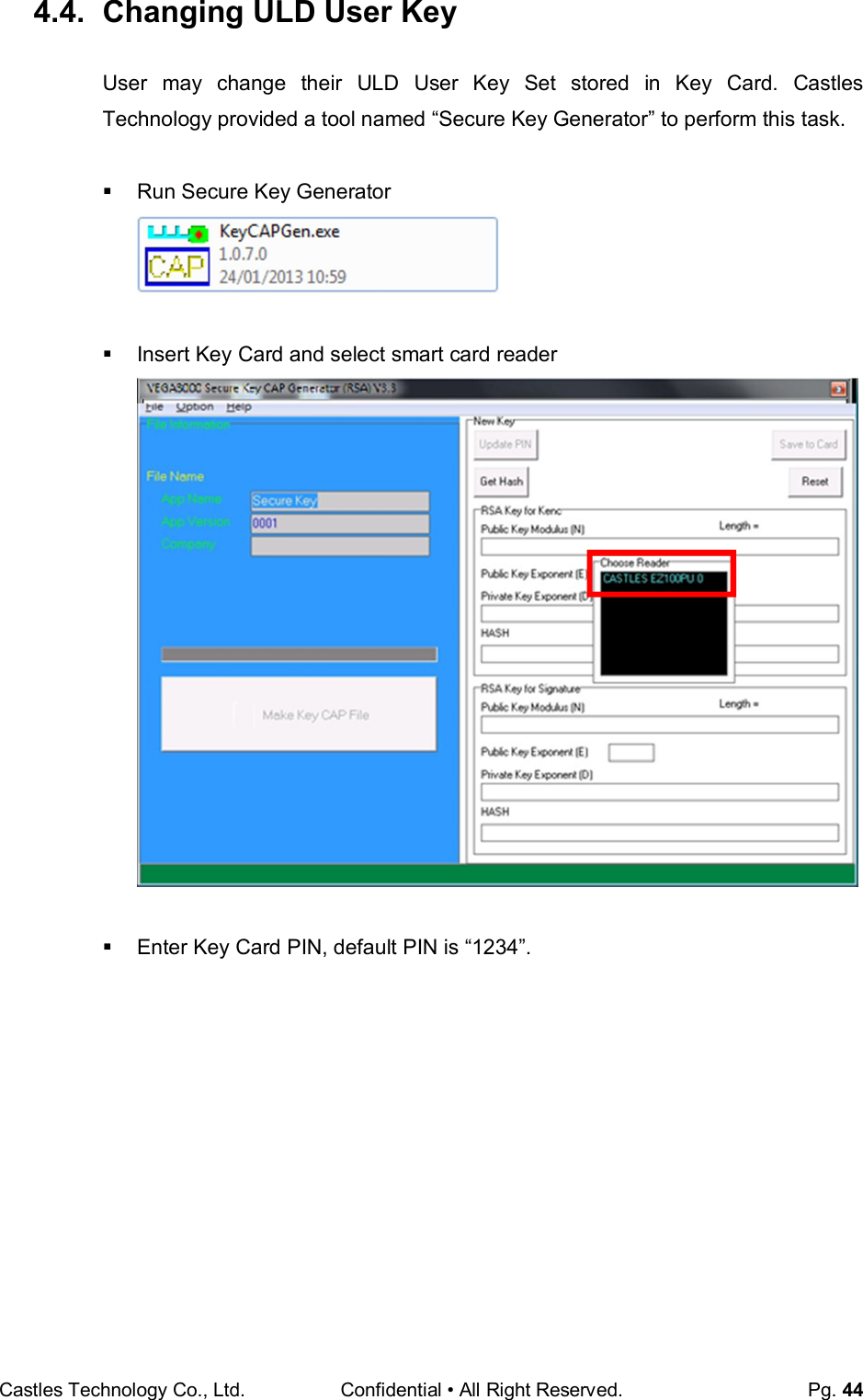
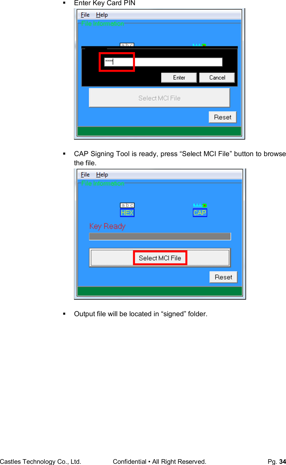
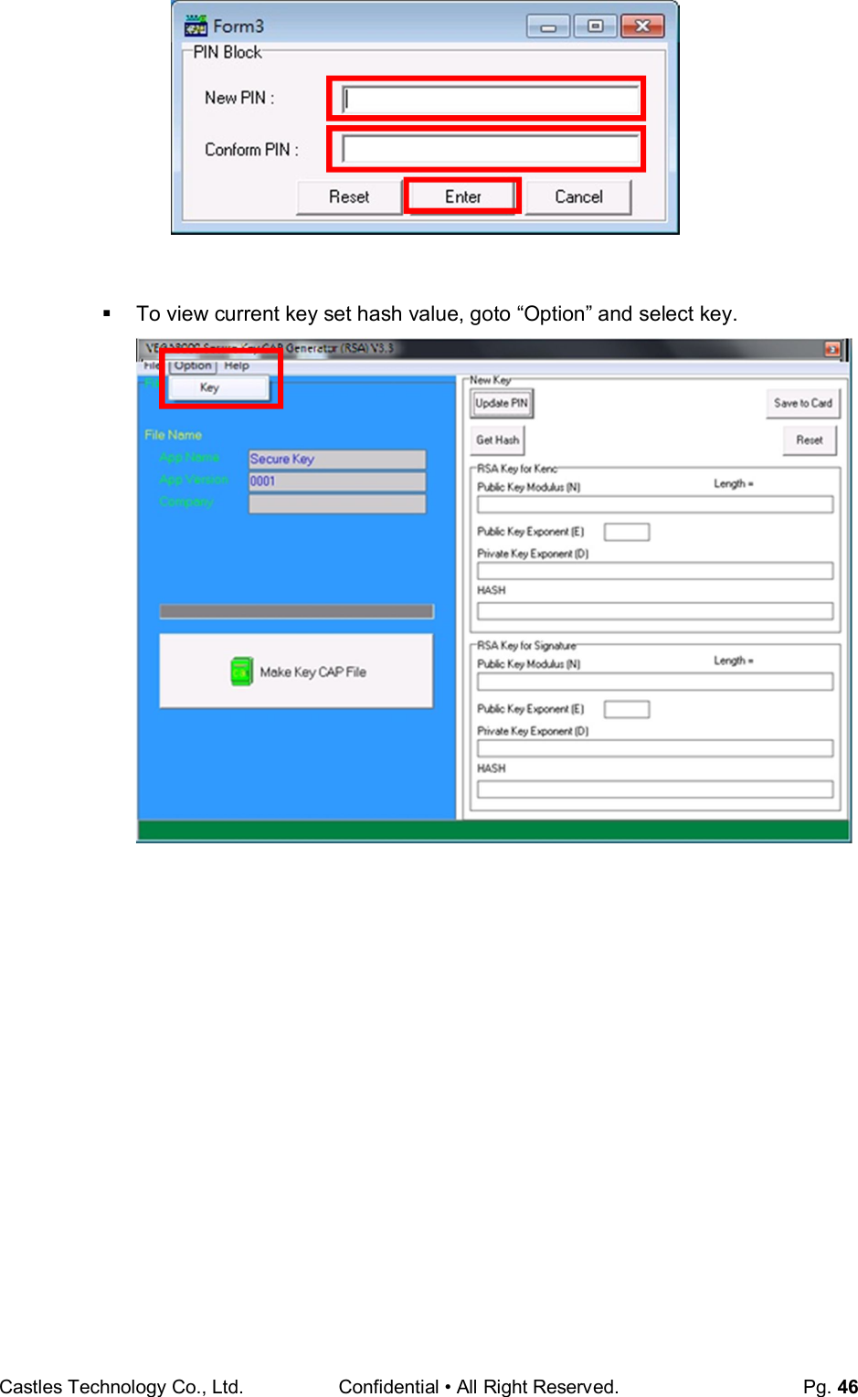
![Castles Technology Co., Ltd. Confidential • All Right Reserved. Pg. 45 To change Key Card PIN, press “Update PIN” button. If not, please skip this steps. Enter new PIN, enter new PIN again to confirm, then press [Enter] button to change PIN in Key Card.](https://usermanual.wiki/CASTLES-TECHNOLOGY/UPT1000/User-Guide-3285958-Page-45.png)
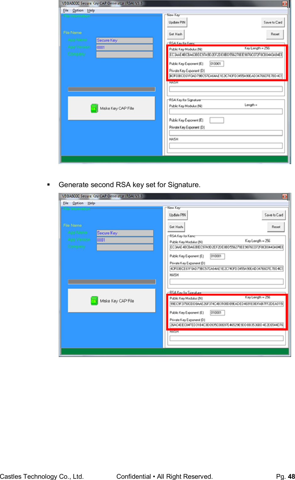
![Castles Technology Co., Ltd. Confidential • All Right Reserved. Pg. 49 Click [Get Hash] button to calculate the hash value for key sets. Please copy down all the values into a text file and keep in a safe place. You will need this if you need to create duplicate Key Card. To generate the key CAP for the newly generated user key set, press [Make Key CAP File] button.](https://usermanual.wiki/CASTLES-TECHNOLOGY/UPT1000/User-Guide-3285958-Page-49.png)
![Castles Technology Co., Ltd. Confidential • All Right Reserved. Pg. 50 The output file will be located in the Secure Key Generator folder. To update the newly generated key set to Key Card, press [Save to Card] button to write the key set to Key Card. SecureKeyGenerator key.mci key.cap](https://usermanual.wiki/CASTLES-TECHNOLOGY/UPT1000/User-Guide-3285958-Page-50.png)
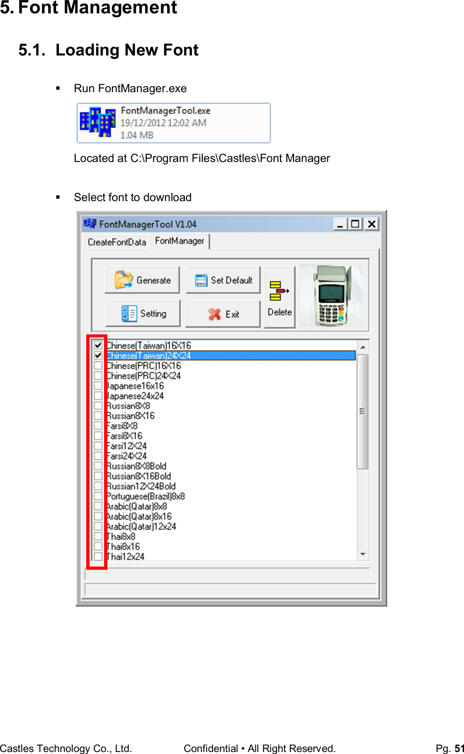
![Castles Technology Co., Ltd. Confidential • All Right Reserved. Pg. 52 Press [Setting] button to configure the type. Select VEGA5000, press [Save] button to save and return font manager. Press [Generate] to create the font file.](https://usermanual.wiki/CASTLES-TECHNOLOGY/UPT1000/User-Guide-3285958-Page-52.png)
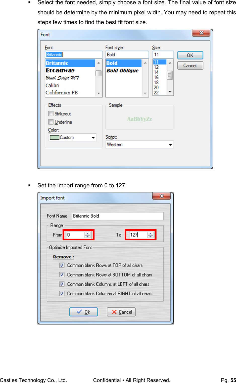
![Castles Technology Co., Ltd. Confidential • All Right Reserved. Pg. 54 5.2. Custom Font User may create font they preferred for displaying or printing on UPT1000. There are two zone defined: Zone 0x00 ~ 0x7F – ASCII characters, you may replace with the font type preferred or your own language character set. Zone 0x80 ~ 0xFF – Free to use, you may use for symbols. Following steps demonstrate how to create a 12x24 font. Run GLCD Font Creator Select [File] [New Font] [Import An Existing System Font]](https://usermanual.wiki/CASTLES-TECHNOLOGY/UPT1000/User-Guide-3285958-Page-54.png)
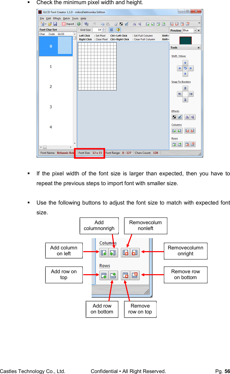
![Castles Technology Co., Ltd. Confidential • All Right Reserved. Pg. 57 After adjust font size, select [File] [Export for MicroElektronika]. Select output format as [mikroC].](https://usermanual.wiki/CASTLES-TECHNOLOGY/UPT1000/User-Guide-3285958-Page-57.png)
![Castles Technology Co., Ltd. Confidential • All Right Reserved. Pg. 58 Remove comment “// Code for char “from offset 0x00 to 0x1F. Remove empty line if found. Then click [Save] button to save to file. Run Font Manager Tool. Click [Setting] button Remove Remove Remove Remove](https://usermanual.wiki/CASTLES-TECHNOLOGY/UPT1000/User-Guide-3285958-Page-58.png)
![Castles Technology Co., Ltd. Confidential • All Right Reserved. Pg. 59 Enter the file name, font id, and select the size. Click [Create] button, and select the C file previously created using GLCD Font Generator.](https://usermanual.wiki/CASTLES-TECHNOLOGY/UPT1000/User-Guide-3285958-Page-59.png)
![Castles Technology Co., Ltd. Confidential • All Right Reserved. Pg. 60 Select [Font Manager] tab and tick the newly createdfont, and press [Generate] button to export to FNT file.](https://usermanual.wiki/CASTLES-TECHNOLOGY/UPT1000/User-Guide-3285958-Page-60.png)
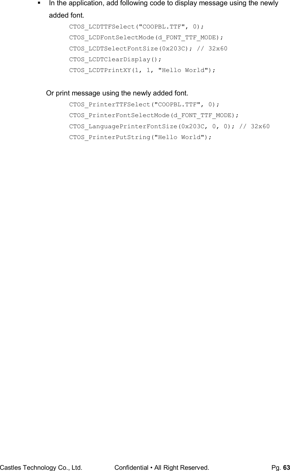
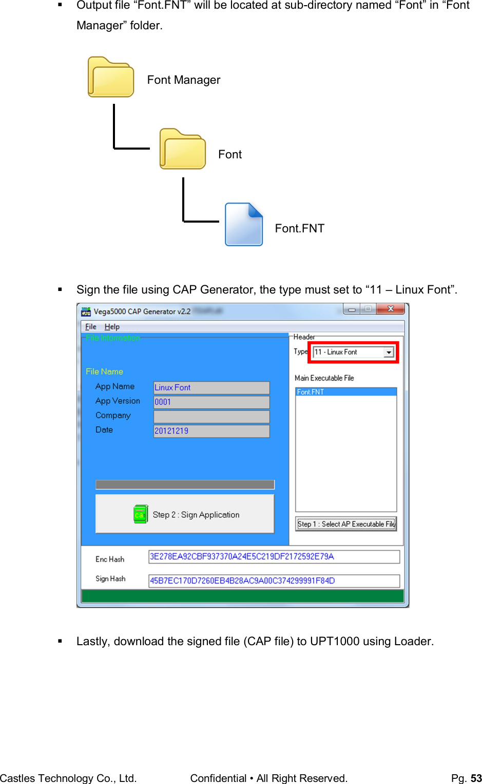
![Castles Technology Co., Ltd. Confidential • All Right Reserved. Pg. 61 Use CAP Generator to convert the FNT file to CAP. Set type to [11 – Linux Font], press [Step 1] button select the FNT file. Then press [Step 2] to generate CAP file. Download the font CAP file to UPT1000. In the application, add following code to display message using the newly created font. CTOS_LanguageConfig(0xA000,d_FONT_12x24,0,d_FALSE); CTOS_LanguageLCDSelectASCII(0xA000); CTOS_LCDTPrintXY(1, 1, "ABCDEFGH"); Or print message using the newly created font. CTOS_LanguagePrinterSelectASCII(0xA000); CTOS_PrinterPutString("ABCDEFGH");](https://usermanual.wiki/CASTLES-TECHNOLOGY/UPT1000/User-Guide-3285958-Page-61.png)
![Castles Technology Co., Ltd. Confidential • All Right Reserved. Pg. 62 5.3. Using TrueType Font (TTF) TrueType Font (TTF) is supported in UPT1000. You can download the TrueType font to UPT1000 for displaying or printing. Following steps demonstrate how to use “Cooper Black” TrueType font. Copy the TTF file needed to an empty folder. Use CAP Generator to convert the TTF file to CAP. Set type to [11 – Linux Font], press [Step 1] button select the TTF file. Then press [Step 2] to generate CAP file. Download the font CAP file to UPT1000. TTF COOPBL.TTF](https://usermanual.wiki/CASTLES-TECHNOLOGY/UPT1000/User-Guide-3285958-Page-62.png)