CASTLES TECHNOLOGY UPT1000 POS Terminal User Manual
CASTLES TECHNOLOGY CO., LTD. POS Terminal Users Manual
Users Manual

UPT1000
Book 2
User Manual
Confidential
Version 1.1
Jan. 2017
CASTLES TECHNOLOGY
Castles Technology Co., Ltd.
6F, No. 207-5, Sec. 3, Beixin Rd., XindianDistrict,
New Taipei City 23143, Taiwan R.O.C.
http://www.castech.com.tw
Castles Technology Co., Ltd. Confidential • All Right Reserved. Pg. 2
WARNING
Information in this document is subject to change without prior notice.
No part of this publication may be reproduced, transmitted, stored in a retrieval
system, nor translated into any human or computer language, in any form or by any
means, electronic, mechanical, magnetic, optical, chemical, manual, or otherwise,
without the prior written permission of Castles Technology Co., Ltd.
All trademarks mentioned are proprietary of their respective owners.

Castles Technology Co., Ltd. Confidential • All Right Reserved. Pg. 3
Revision History
Version
Date Descriptions Author
1.0 Dec 19, 2016 Initial creation. Jeff
1.1 Jan 11, 2017 Add “7. Appinex” and “7.1 Cautions”. Jeff
Castles Technology Co., Ltd. Confidential • All Right Reserved. Pg. 4
Contents
1. Introduction .................................................................................................................. 6
2. Hardware Setup............................................................................................................ 7
2.1. Parts of the UPT1000 .......................................................................................... 7
2.2. Communication Support ...................................................................................... 8
3. Basic Operation ........................................................................................................... 9
3.1. Program Manager ................................................................................................ 9
3.2. Download AP ..................................................................................................... 10
3.3. System Info........................................................................................................ 11
3.4. Memory Status .................................................................................................. 12
3.5. System Settings ................................................................................................. 13
3.6. Test Utility .......................................................................................................... 16
3.7. Factory Reset .................................................................................................... 18
3.8. Power Off .......................................................................................................... 19
3.9. FK PWD Change ............................................................................................... 20
3.10. Share Object Management ................................................................................ 21
3.11. Embedded TMS ................................................................................................. 22
3.12. Font Mng ........................................................................................................... 23
3.13. Debug Tools ...................................................................................................... 24
3.14. ULD Key Hash ................................................................................................... 25
3.15. HW Detect ......................................................................................................... 26
3.16. Bluetooth Setup ................................................................................................. 27
3.17. Plug-in Mng ....................................................................................................... 28
3.18. Key Injection ...................................................................................................... 29
4. Secure File Loading ................................................................................................... 30
4.1. ULD Key System ............................................................................................... 30
4.1.1. ULD Manufacturer Key ........................................................................... 30
4.1.2. ULD User Key ........................................................................................ 32
4.1.3. Key Change ........................................................................................... 32
4.2. File Signing ........................................................................................................ 33
4.2.1. Signing Kernel Module ........................................................................... 33
4.2.2. Signing User Files .................................................................................. 35
4.3. File Loading ....................................................................................................... 39
4.3.1. Download by User Loader ...................................................................... 39
Castles Technology Co., Ltd. Confidential • All Right Reserved. Pg. 5
4.3.2. Download by Removable Media ............................................................. 42
4.4. Changing ULD User Key.................................................................................... 44
5. Font Management ...................................................................................................... 51
5.1. Loading New Font.............................................................................................. 51
5.2. Custom Font ...................................................................................................... 54
5.3. Using TrueType Font (TTF) ............................................................................... 62
6. Technical Notes ......................................................................................................... 64
6.1. Serial Cable PIN Assignment ............................................................................. 64
7. Appendix .................................................................................................................... 65
7.1. Cautions ............................................................................................................ 65
Castles Technology Co., Ltd. Confidential • All Right Reserved. Pg. 6
1. Introduction
This document provides a guideline on operating and configuring Castles UPT1000 .
The scope of this document includes setting up the UPT1000, basic operation,
application life cycle, and some advance features.
Castles Technology Co., Ltd. Confidential • All Right Reserved. Pg. 7
2. Hardware Setup
2.1. Parts of the UPT1000
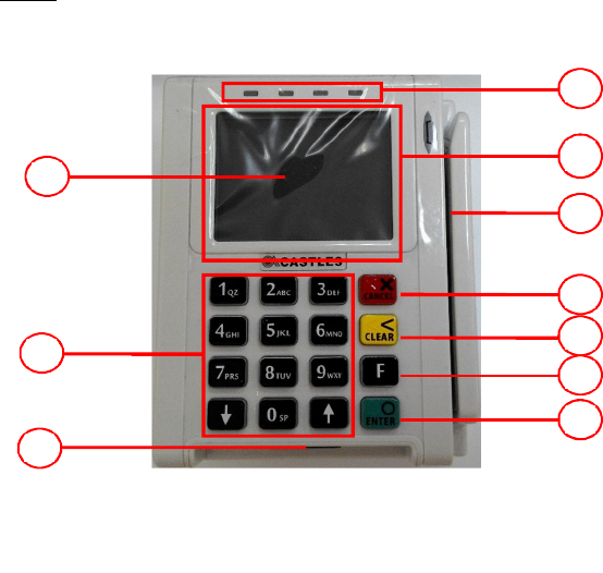
Front
1. LCD Display (Color TFT)
2. Keypad
3. Smart Card Reader
4. Enter Key
5. Return Key (RFU)
6. Clear Key
7. Cancel Key
8. Magnetic Stripe Reader
9. Contactless Card Landing
Zone
10. LED indicator
UPT1000
1
2
3
5
8
9
10
6
7
4
Castles Technology Co., Ltd. Confidential • All Right Reserved. Pg. 8
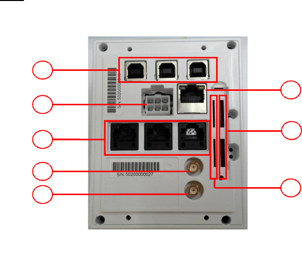
Rear
11. USB port 1~3
12. MDB (power connector)
13. RS232 port 1~3
14. BT antenna socket
15. GPRS antenna socket
16. GSM SIM Card Slots 1~2
17. SAM Card Slots 1~4
18. LAN port
2.2. Communication Support
1. Ethernet
2. BT
3. UMTS 850/1900
4. GPRG 850/1900
UPT1000
11
12
13
17
14
18
15
16

Castles Technology Co., Ltd. Confidential • All Right Reserved. Pg. 9
3. Basic Operation
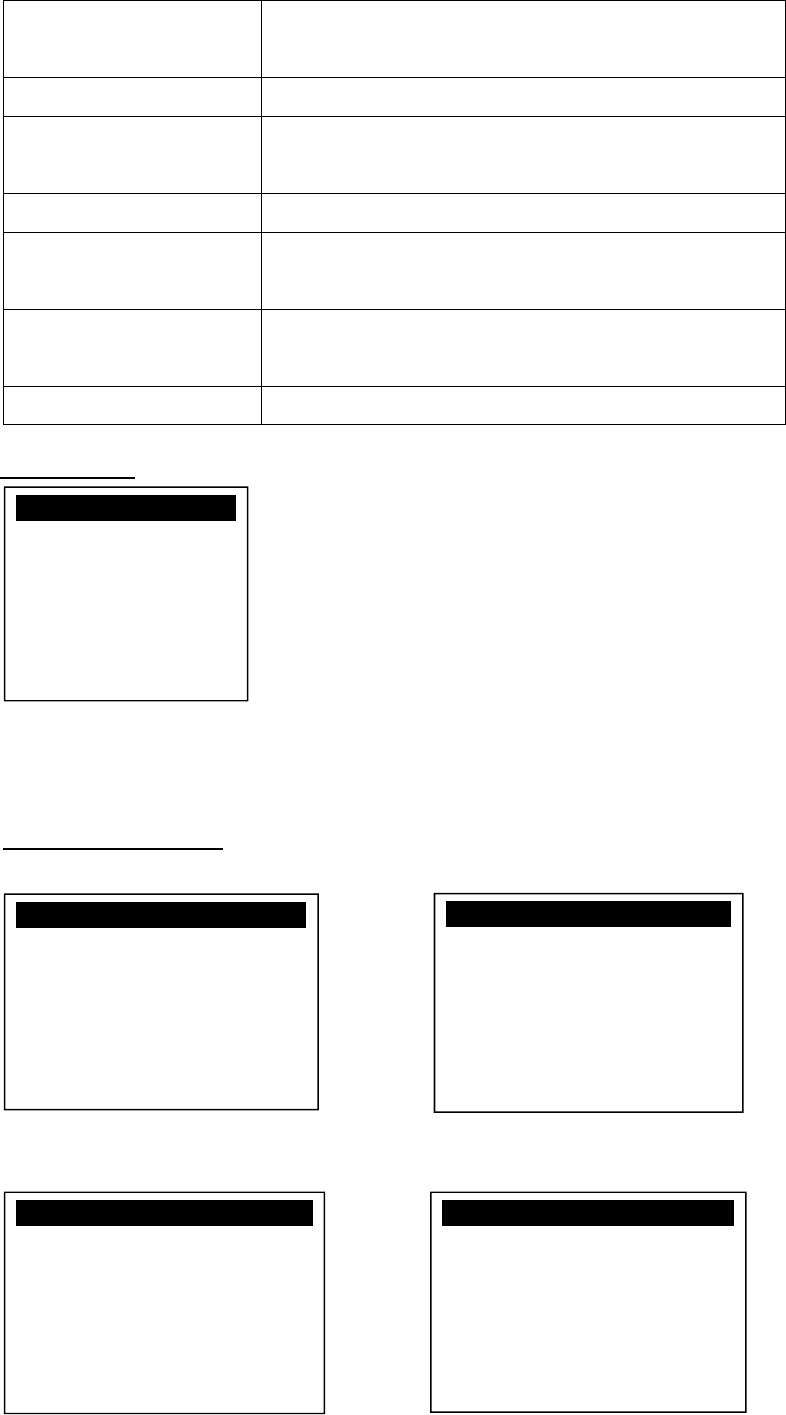
3.1. Program Manager
Once the power is on in normal status, UPT1000 will enter Program Manager if
no default application selected. All user applications are listed in Program
Manager. Users can select an application and run the application, view the
application info, delete the application, or set application to the default one to run
once the power is on. Users may enter System Menu to configure UPT1000
settings.
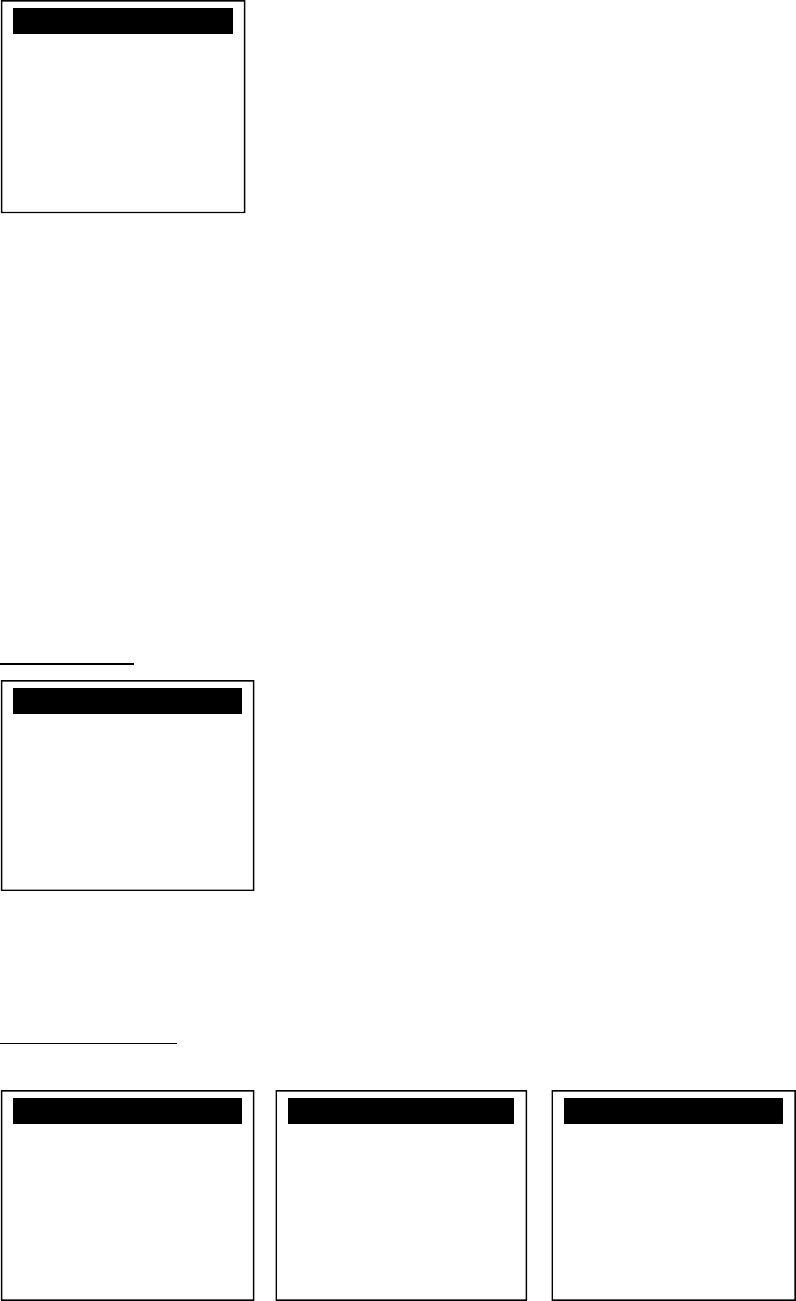
Program Manager
Press[0] button to enter System Menu.
Press [1] button to toggle default application selection.
Press [2] button to delete application.
Press [3] button to view application info.
Press [OK] button to run application.
Press [ ↑ ] or [↓] as the up and down buttonto select application.
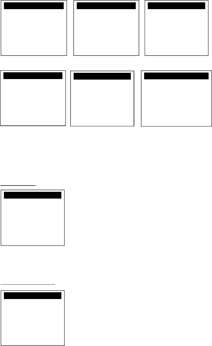
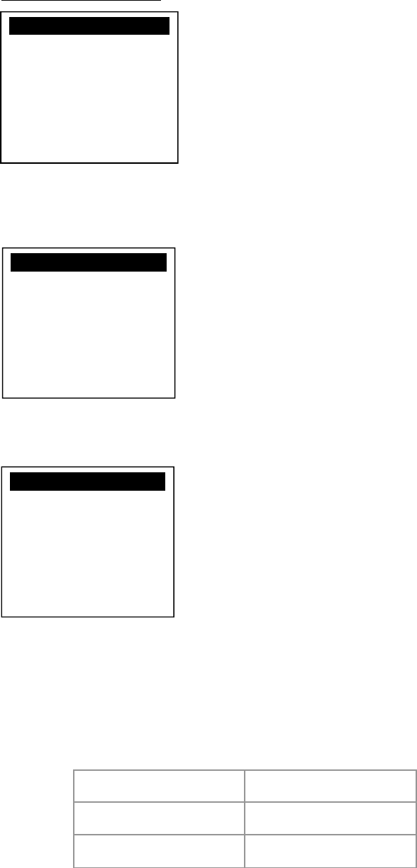
System Menu
Page 1
Press [↓] button to page 2.
Program Manager
-----------01/02
1.App1
2.App2
0:Download
System Menu
1.Download AP
2.System Info
3.Memory Status
4.Sys Settings
5.Test Utility
6.Factory Reset
7.Power Off

Castles Technology Co., Ltd. Confidential • All Right Reserved. Pg. 10
Page 2
Press [↑] button to page1.
Press [↓] button to page3.
Page 3
Press [↑] button to page2.
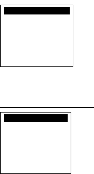
3.2. Download AP
Download user application or kernel modules firmware.
System Menu
Press [1] button to enter Download AP menu.
Download AP Menu
System Menu
1.FK PWD Change
2.Share obj Mng
3.Embedded TMS
4.Font Mng
5.Debug Tools
6.ULD KEY HASH
7
.HW Detect
System Menu
1.Download AP
2.System Info
3.Memory Status
4.Sys Settings
5.Test Utility
6.Factory Reset
7.Power Off
System Menu
1.BluetoothSetup
2.Plug-in Mng
3.Key Injection
Castles Technology Co., Ltd. Confidential • All Right Reserved. Pg. 11
Select download source:
Press [1] button to select source as RS232 or USB connection and enter ULD
download mode.
Press [2] button to select source as USB disk.
Press [3] button to select source as SD card. (Not support)
3.3. System Info
View kernel module firmware information.
System Menu
Press [2] button to enter System Info menu.
System Info Menu
Page 1 Page 2 Page 3
Press [↓] button to next page.
Download EX
1.RS232 or USB
2.USB Disk
3.SD Card
Select DW Source
System Menu
1.Download AP
2.System Info
3.Memory Status
4.Sys Settings
5.Test Utility
6.Factory Reset
7.Power Off
SYSTEM INFO
---Kernel Ver---
BIOS :VR0024
SULD :VRF010
LINUXKNL:VR0024
ROOTFS :VR0010
SYSTEM INFO
--- KOVer ---
SECURITY :VR0025
KMS :VR0027
DRV :VR0046
USB :N/A
CIF :VR0025
SAM
:VR
0034
SYSTEM INFO
--- KOVer2 ---
CL :VR0018
SC :VR0011
Castles Technology Co., Ltd. Confidential • All Right Reserved. Pg. 12
Page 4 Page 5 Page 6
Page 8 Page 9 Page 10
3.4. Memory Status
View flash memory and RAM information.
System Menu
Press [3] button to enter Memory Status menu.
Memory Status Menu
SYSTEM INFO
--- SO Ver3 ---
GSM :VR0029
BARCODE :VR0013
TLS :VR0014
CLVW :VR0024
CTOSAPI :VR0039
SYSTEM INFO
--- HWMVer ---
CRDL/ETHE:ONCHIP
CLM-MP : N/A
--- APVer ---
ULDPM :VR0036
SYSTEM INFO
HUSBID:0CA6A050
CUSBID:N/A
--Factory S/N---
FFFFFFFFFFFFFFFF
SYSTEM INFO
----- SOVer-----
UART :VR0017
USBH :VR0011
MODEM :VR0019
ETHERNET :VR0035
FONT :VR0032
LCD
:VR00
42
SYSTEM INFO
---- SO Ver2 ---
PRT :VR0025
RTC :VR0013
ULDPM :VR0029
PPPMODEM :VR0031
KMS :VR0032
FS
:VR001
6
SYSTEM INFO
--EXT SO Ver P.1--
CACLMDL :VR0008
CACLENTRY :VR0008
CAMPP :VR0007
CAVPW :VR0019
CAAEP :VR0004
CAJCT
:VR
00
07
System Menu
1.Download AP
2.System Info
3.Memory Status
4.Sys Settings
5.Test Utility
6.Factory Reset
7.Power Off
MEMORY STATUS
--FLASH Memory--
Total: 130688KB
Used : 44644KB
--SDRAM Memory--
Total: 65408KB
Used :
32384
KB

Castles Technology Co., Ltd. Confidential • All Right Reserved. Pg. 13
3.5. System Settings
View or change system settings.
Setting Descriptions
Key Sound Enable (Y) or disable (N) the beep sound when
pressing any key.
Exec DFLT AP Enable (Y) or disable (N) execution of default
selected application.
USB CDC Mode Enable (Y) or disable (N) USB CDC mode.
FunKey PWD Enable (Y) or disable (N) password protection to
access function key “0” in Program Manager.
PMEnter PWD Enable (Y) or disable (N) password protection to
enter Program Manager.
SET USB Host Enable (Y) or disable (N) USB host mode.
Base USB CDC Enable (Y) or disable (N) USB CDC mode in base
unit. (Not support)
List SHR Lib Enable (Y) or disable (N) to list all shared libraries
in Program Manager.
Key MNG Mode
<TBC>
BATThreshld Battery charging threshold value. (Not support)
Null Cradle Enable (Y) if base is Type Acradle. (Not support)
Debug Mode Enable (Y) or disable (N) console debug mode.
Debug Port Serial port for console debug.
Mobil AutoON Enable (Y) or disable (N) to auto turn on GSM
module after boot up.
Bklit Auto Off Enable (Y) or disable (N) Auto Off LCD Backlight
Bklit Off Time Threshold of Auto Off LCD Backlight
PWR KEY OFF Power keyfunction, power off (Y) or reboot(N)
GDB Mode Enable (Y) or disable (N) GDB (GNU Debugger)
mode. (Needs to download GDB plugin FW first.)
GDB Timeout Set GDB connection timeout.
GDB Channel Set GDB connection channel.
ETHER IP/PORT GDB Ethernet connection setting.
RTC Time Zone Set Time Zone of RTC (Real Time Clock).
Castles Technology Co., Ltd. Confidential • All Right Reserved. Pg. 14
NTP Enable Enable (Y) or disable (N) NTP (Network Time
Protocol) function.
NTP Update Freq Frequency of Network Time Protocol updating.
Halt Timeout Set timeout of AP to get back to Program Manager
whenever AP is in halt state.
PWM Auto Enable (Y) or disable (N) power saving mode.
PWM Mode Select (STB) standby mode or (SLP) sleep mode
for power saving mode.
PWM Time Set time period to make machine enter power
saving mode from idle state.
BAT PROTECT MODE Set battery protect mode. (Not support)
System Menu
Press [4] button to enter System Settings menu.
System Settings Menu
Page 1 Page 2
Page 3 Page 4
System Menu
1.Download AP
2.System Info
3.Memory Status
4.Sys Settings
5.Test Utility
6.Factory Reset
7.Power Off
SYS SETTINGS
Key Sound : Y
Exec DFLT AP : Y
-Default AP Name
USB CDC Mode : Y
FunKey PWD : N
PMEnter PWD : N
2: Next Page
SYS SETTINGS
SET USB Host : N
Base USB CDC : X
List SHR Lib : N
Key MNG Mode : 0
Bat Threshld : X
Null Cradle : X
1: Prev 2: Next
SYS SETTINGS
Debug Mode : N
Debug Port : X
Mobil AutoON : N
Bklit Auto Off : N
BklitOff Time : X
PWR KEY OFF : N
1: Prev 2: Next
SYS SETTINGS
GDB Mode : GMT
GDB Timeout : N
GDB Channel : X
ETHER IP/PORT
1: Prev 2: Next

Castles Technology Co., Ltd. Confidential • All Right Reserved. Pg. 15
Page 5 Page 6
Press [↑] or [↓]button to select setting.
Press [OK] button to change the setting value.
Press [˂ ] button to toggle Y N Y.
Press [1] button to previous page.
Press [2] button to next page.
SYS SETTINGS
RTC Time Zone : GMT
NTP Enable : N
NTP Update Freq : X
1: Prev 2: Next
SYS SETTINGS
Halt Timeout : 0
PWM Auto : X
PWM Mode : X
PWM Time : X
BAT PROTECT MODE : X
1: Prev Page

Castles Technology Co., Ltd. Confidential • All Right Reserved. Pg. 16
3.6. Test Utility
Perform hardware components diagnosis.
System Menu
Press [5] button to enter Test Utility menu.
Test Utility Menu
Page 1
Press [1] and [OK] to diagnose LCD.
Press [2] and [OK] to diagnose keyboard.
Press [3] and [OK] to diagnose flash memory.
Press [4] and [OK] to diagnose smart card module.
Press [5] and [OK] to diagnose backlight.
Press [6] and [OK] to diagnose magnetic stripe card reader.
Press [↓] button to page 2.
System Menu
1.Download AP
2.System Info
3.Memory Status
4.Sys Settings
5.Test Utility
6.Factory Reset
7.Power Off
Main Menu 9123
1.LCD
2.Keyboard
3.Flash
4.Smart Card
5.Backlight
6.MSR
-
> 1/3

Castles Technology Co., Ltd. Confidential • All Right Reserved. Pg. 17
Page 2
Press [7] and [OK] to diagnose LED.
Press [8] and [OK] to diagnose RTC.
Press [9] and [OK] to check Printer.
Press [10] and [OK] to check FONT file in UPT1000.
Press [11] and [OK] to check CL transparent.
Press [12] and [OK] to test Cantactless Card.
Press [↑] button to page 1.
Press [↓] button to page 3.
Page 3
Press [13] and [OK] to execute SD Card Test. (Not support)
Press [14] and [OK] to testfunctionality ofWiFi.
Press [15] and [OK] to test functionality of power saving.
Press [16] and [OK] to test functionality of multiple communication ways.
Press [17] and [OK] to testfunctionality of Bluetooth.
Press [↑] button to page2.
Main Menu 9123
13.SD Card Test
14.Wi-Fi Test
15.Power Saving
16.Comm Menu
17.BT Test
-
> 3/3
Main Menu 9123
7.LED
8.RTC
9.Printer
10.Font
11.CL Transparent
12.CL Card Test
-
> 2/3

Castles Technology Co., Ltd. Confidential • All Right Reserved. Pg. 18
3.7. Factory Reset
Perform factory reset, all user application, fonts and data will be deleted.
System Menu
Press [6] button to enter Factory Reset menu.
Press [OK].
Enter password and press [OK].
Enter factory reset password.(Default password: 8418)
System Menu
1.Download AP
2.System Info
3.Memory Status
4.Sys Settings
5.Test Utility
6.Factory Reset
7.Power Off
FacRest Password
Enter Password:
****
FacRest Password
OK to reset?

Castles Technology Co., Ltd. Confidential • All Right Reserved. Pg. 19
Start erasing, and then go back to Program Manager.
3.8. Power Off
Power off the machine.
System Menu
Press [7] button to power off the machine.
System Menu
1.Download AP
2.System Info
3.Memory Status
4.Sys Settings
5.Test Utility
6.Factory Reset
7.Power Off
FacRestPassword
Enter Password:
****
Erasing…
Castles Technology Co., Ltd. Confidential • All Right Reserved. Pg. 20
3.9. FK PWD Change
Change the keyin password.
System Menu (Page 2)
Press [1] button to enter Password Manager Menu.
Enter current password. (Default password is "0000")
Enter new password.
Enter new password again to confirm.
User must have to change the Default key to user own key at the first time.
The Default Key Value in Password Manager is as below:
Function Key
0000
PMEnter Key
0000
Factory Key
8418
FunKey Password
Enter Password:
****
FunKey Password
New Password:
****
Confirm Password
****
PWD Changed OK
System Menu
1.FK PWD Change
2.Share obj Mng
3.Embedded TMS
4.Font Mng
5.Debug Tools
6.ULD KEY HASH
7
.HW Detect
Castles Technology Co., Ltd. Confidential • All Right Reserved. Pg. 21
3.10. Share Object Management
View share object in machine .
System Menu (Page 2)
Press [2] button to enter Share Object Management menu.
Share Object Management Menu
Press [1] button to view shared libraries.
Press [2] button to view shared files.
Share objMng
1.Share LIB
2.Share File
System Menu
1.FK PWD Change
2.Share obj Mng
3.Embedded TMS
4.Font Mng
5.Debug Tools
6.ULD KEY HASH
7
.HW Detect

Castles Technology Co., Ltd. Confidential • All Right Reserved. Pg. 22
3.11. Embedded TMS
TMS (Terminal Managerment System) setting menu.
System Menu (Page 2)
Press [3] button to enter TMS setting menu.
CASTLES TMS
Press [1] button to connect server.
Press [2] button to enter system config menu.
Press [3] button to reset config.
Press [4] button to set compatible config.
CASTLES TMS
1.Connect Server
2.System Config
3.Reset Config
4.CompatibleConfig
System Menu
1.FK PWD Change
2.Share obj Mng
3.Embedded TMS
4.Font Mng
5.Debug Tools
6.ULD KEY HASH
7
.HW Detect

Castles Technology Co., Ltd. Confidential • All Right Reserved. Pg. 23
3.12. Font Mng
View Font Management.
System Menu (Page 2)
Press [4] button to view Font Management.
FontManagment
Press [1] button to view FNT Font list.
Press [2] button to view TTF Font list.
Font Mng
1.FNT File
2.TTF File
System Menu
1.FK PWD Change
2.Share obj Mng
3.Embedded TMS
4.Font Mng
5.Debug Tools
6.ULD KEY HASH
7
.HW Detect

Castles Technology Co., Ltd. Confidential • All Right Reserved. Pg. 24
3.13. Debug Tools
Get core dump or debug log.
System Menu (Page 2)
Press [5] button to enter Debug Tools menu.
Debug Tools
Press [1] button to enter core dump menu.
Press [2] button to enter debug log menu.
Debug Tools
1.Core Dump
2.Debug Log
System Menu
1.FK PWD Change
2.Share obj Mng
3.Embedded TMS
4.Font Mng
5.Debug Tools
6.ULD KEY HASH
7
.HW Detect

Castles Technology Co., Ltd. Confidential • All Right Reserved. Pg. 25
3.14. ULD Key Hash
View ULD user key hash value.
System Menu (Page 2)
Press [6] button to view hash value.
USER ENV KEY
DA9C91FE668DF4B6D637
CDBCCEC201444AA2C7FF
USER SIGN KEY
D52F36A1B569B5ABBA4F
EAEFB34BEC000101D58C
System Menu
1.FK PWD Change
2.Share obj Mng
3.Embedded TMS
4.Font Mng
5.Debug Tools
6.ULD KEY HASH
7
.HW Detect

Castles Technology Co., Ltd. Confidential • All Right Reserved. Pg. 26
3.15. HW Detect
Run hardware detection.
System Menu (Page 2)
Press [7] button to run HW detection.
Press any key to reboot system.
HW TYPE
Original
HW-TYPE : EGCB
New
HW-TYPE : EGCB
Please Any Key.
System Menu
1.FK PWD Change
2.Share obj Mng
3.Embedded TMS
4.Font Mng
5.Debug Tools
6.ULD KEY HASH
7
.HW Detect

Castles Technology Co., Ltd. Confidential • All Right Reserved. Pg. 27
3.16. Bluetooth Setup
Setup Bluetooth config.
System Menu (Page 2)
Press [1] button to enter Bluetooth setting menu.
Bluetooth Setup
Press [1] button to enter Handset BT Setup menu.
Press [2] button to enter Cradle CH Setup menu.
System Menu
1.Bluetooth Setup
2.Plug-in Mng
3.Key Injection
Bluetooth Setup
1.Handset BT Setup
2.Cradle CH Setup

Castles Technology Co., Ltd. Confidential • All Right Reserved. Pg. 28
3.17. Plug-in Mng
View Plug-in Management.
System Menu (Page 2)
Press [2] button to view Plug-in Management.
Press [↑] or [↓] button to select item.
Press [1] button to get item information.
Press [2] button to delete item.
Plug-in Mng
1.Bluetooth :V9116
1.I
n
fo 2.Del
System Menu
1.Bluetooth Setup
2.Plug-in Mng
3.Key Injection
4.TP Calibration
System Menu
1.Bluetooth Setup
2.Plug-in Mng
3.Key Injection

Castles Technology Co., Ltd. Confidential • All Right Reserved. Pg. 29
3.18. Key Injection
Key Injection function. (Factory use only.)
System Menu (Page 3)
Press [3] button to view Key Injection.
Key Injection
Waiting for
Command
System Menu
1.Bluetooth Setup
2.Plug-in Mng
3.Key Injection

Castles Technology Co., Ltd. Confidential • All Right Reserved. Pg. 30
4. Secure File Loading
Castles implemented an interface named User Loader(ULD) to provide secure file loading to
system memory. Loading of user application, kernel firmware, font and others must use User
Loader.
The loading process is secure by signing the files using ULD Key System.
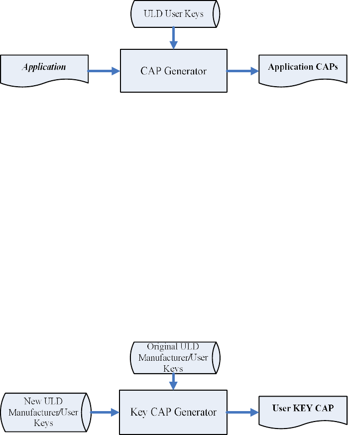
4.1. ULD Key System
The ULD Key System uses two key sets for securely managing the kernel
updating and application downloading. Each key set contains two RSA key pairs.
One is used for key encryption and the other is used for signature. These two key
sets are specified as below:
ULD Manufacturer Key Set
ULD Manufacturer Key Encryption Key (RSA)
ULD Manufacturer Signature Key (RSA)
ULD User Key Set
ULD User Key Encryption Key (RSA)
ULD User Signature Key (RSA)
For UPT1000, the RSA key length is 2048bits.
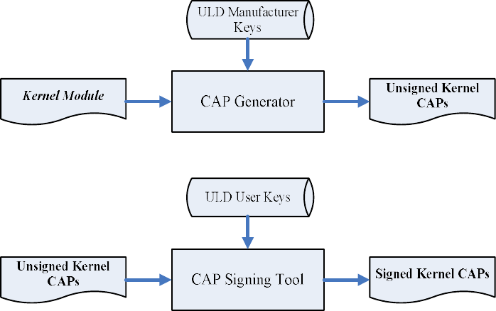
4.1.1. ULD Manufacturer Key
The system consists of several kernel modules. These kernel modules
are provided by the Manufacturer, and released in CAP format file with
encryption and signing via ULD Manufacturer Keys.
The ULD Manufacturer keys are managed and maintained by the
manufacturer. The manufacturer uses these keys to generate kernel
CAP files for updating the system. However, the system is not permitted
to be updated with these kernel CAP files directly generated by the
manufacturer. This is because only the user can have the privilege to
decide whether the system is to be updated. Therefore, before system
Castles Technology Co., Ltd. Confidential • All Right Reserved. Pg. 31
updating, the kernel CAP files must be “signed” via ULD User Key to get
the user permission. For simple expression, we call the kernel CAP files
generated by the manufacturer as “unsigned kernel CAP(s)” and call the
kernel CAP files “signed” by the user later as “signed kennel CAP(s)”.
Notes:
1. The kernel modules are encrypted by a random-generated 3DES
key, which is retrieved from the Key Encryption Block of the CAP by
ULD Manufacturer Key Encryption Key, not directly encrypted by ULD
RSA Key.
2. The “sign” action via ULD User Keys actually is done by” the second
encryption”. “The second encryption” is done by using the random-
generated 3DES key, which is encrypted by ULD User Key Encryption
Key, to perform Triple DES encryption again on the cipher data segment
of the kernel CAP files. This ensures that the system cannot retrieve the
correct data from the kernel CAPs without the user permission.
Castles Technology Co., Ltd. Confidential • All Right Reserved. Pg. 32
4.1.2. ULD User Key
ULD User Key are used to encrypt and sign the user/shared
applications. In addition, they are as goalkeepers to prevent the system
updating without user permission. This is done by the kernel CAPs
which are encrypted and signed by the manufacturer having to perform
the “signed’ action via ULD User Keys.
Notes: Applications are encrypted by a random-generated 3DES key,
which is retrieved from the Key Encryption Block of the CAP by ULD
User Key Encryption Key, not directly encrypted by ULD RSA Key.
4.1.3. Key Change
The ULD RSA Keys are able to be changed. The system uses a special
CAP file, KEY CAP, for the manufacturer and user to change their own
keys. The KEY CAP contains a new set of ULD keys (Key Encryption
Key and Signature Key). These new keys are encrypted and signed via
the original keys. In other words, if the user would like to change the
ULD User Keys, they have to use their original ULD User Keys with the
new ULD User Keys to generate a KEY CAP.
Castles Technology Co., Ltd. Confidential • All Right Reserved. Pg. 33
4.2. File Signing
4.2.1. Signing Kernel Module
Castles will release new version of kernel module in “unsigned” form.
This files required to sign with ULD User Key before it can load to
UPT1000.
Castles Technology provides a tool named “CAP Signing Tool” to
perform this task.
The CAP Signing Tool is located at:
C:\Program Files\Castles\UPT1000\tools\Signing Tool
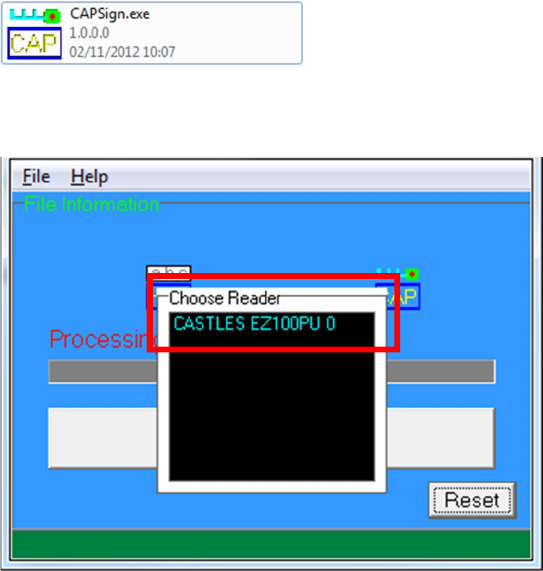
Run CAP Signing Tool
Insert Key Card and select smart card reader
Castles Technology Co., Ltd. Confidential • All Right Reserved. Pg. 34
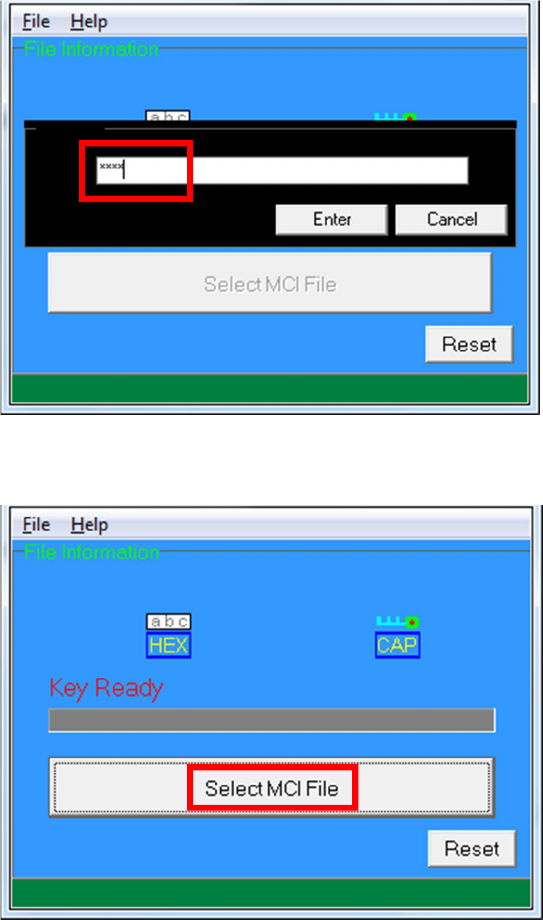
Enter Key Card PIN
CAP Signing Tool is ready, press “Select MCI File” button to browse
the file.
Output file will be located in “signed” folder.

Castles Technology Co., Ltd. Confidential • All Right Reserved. Pg. 35
4.2.2. Signing User Files
Following files are required to sign before load to UPT1000. This is to
ensure the application data and codes confidential and integrity. The
output file will be “CAP” file which format is defined by Castles.
User application
User application data files
User application library
Font file
Share library
Share files
System setting
Key CAP (Manufacturer ULD Key Set)
Castles Technology provided a tool named “CAP Generator” to perform
this task.
The CAP Generator is located at:
C:\Program Files\Castles\UPT1000\tools\CAPG (KeyCard)
Run CAP Generator
Castles Technology Co., Ltd. Confidential • All Right Reserved. Pg. 36
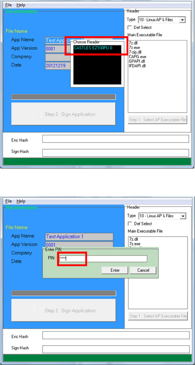
Insert Key Card and select smart card reader
Enter Key Card PIN
Castles Technology Co., Ltd. Confidential • All Right Reserved. Pg. 37
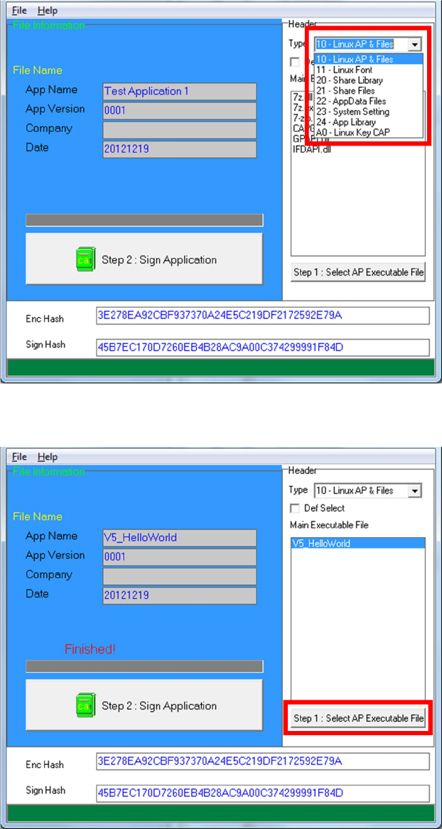
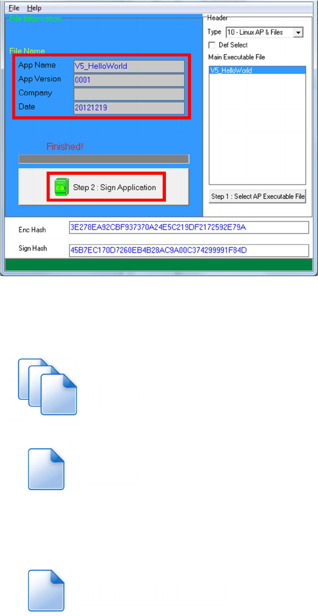
CAP Generator is ready, select the correct Type from the list.
Press “Step 1: Select AP Executable File” to select file to sign. This
is valid for all the files to sign.
Castles Technology Co., Ltd. Confidential • All Right Reserved. Pg. 38
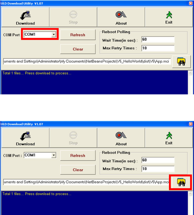
Enter file details and press “Step 2: Sign Application” to sign the file.
This is valid for all the files to sign.
The output file will be in a set. A “mci” file with one or more “CAP”
files.CAP file contents the signed file binaries, where MCI file
contents the list of CAP files.
Note: If user would like to load multiple set of signed file, create a new
file with extension of “mmci”. Then put the mmci file contents with the list
of mci file.
App.CAP
App.mci
MultiApp.mmci

Castles Technology Co., Ltd. Confidential • All Right Reserved. Pg. 39
4.3. File Loading
There are several ways of loading file to UPT1000.
Download by User Loader
Download by removable media
Download by user application
Download by Castles TMS
User Loader is a tool provided by Castles Technology. It’s the formal way to
download file to UPT1000.
User may implement their own ways of updating application or files using CTOS
API provided, CTOS_UpdateFromMMCI().
Castles TMS (CTMS or CASTLES Terminal Management System) is provided by
Castles Technology. It uses to perform remote download via Ethernet,
GPRS/UMTS or modem.
4.3.1. Download by User Loader
The User Loader works for UPT1000.
The Loader is located at:
C:\Program Files\Castles\UPT1000\tools\Loader
Run User Loader
Castles Technology Co., Ltd. Confidential • All Right Reserved. Pg. 40
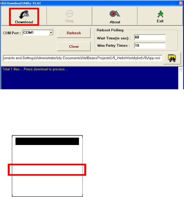
Select COM port
Browse and select mci file or mmci file
Setup UPT1000 to enter download mode
Press [0] button in Program Manager (PM)
Press [1] button to select “1. Download AP“
Press [1] button again to select download via RS232 or USB
Castles Technology Co., Ltd. Confidential • All Right Reserved. Pg. 41
Press “Download” button to start.
Note: To download using USB cable, UPT1000 must enable CDC
mode. Set USB CDC Mode to Y.
SYS SETTINGS
Key Sound : Y
Exec DFLT AP: Y
-AP Name
USB CDC Mode: Y
FunKeyPWD : N
PMEnterPWD : N
2: Next Page
Castles Technology Co., Ltd. Confidential • All Right Reserved. Pg. 42
4.3.2. Download by Removable Media
The file download process can be achieved without PC by using
removable media, USB flash drive. We recommend don’t put
unwantedfile to removable media, as it will increase the time during
detection.
Create a folder name “vxupdate” under root directory.
Place the mci file and cap file to “vxupdate” folder.
Note: If user would like to load multiple application, create a new file
with extension of “mmci”. Then put the mmci file contents with the
list of mci file.
root
vxupdate
root
vxupdate
App.CAP
App.mci
MultiApp.mmci

Castles Technology Co., Ltd. Confidential • All Right Reserved. Pg. 43
Insert removable media to UPT1000, and select the removable
media type in “Download AP” menu.
Download AP Menu
o Press [2] button to select USB flash drive.
o Press [3] button to select MicroSD card. (Not support)
Finally, UPT1000 will process the file in “vxupdate” folder.
Download EX
1.RS232 or USB
2.USB Disk
3.SD Card
Select DW Source
Castles Technology Co., Ltd. Confidential • All Right Reserved. Pg. 44
4.4. Changing ULD User Key
User may change their ULD User Key Set stored in Key Card. Castles
Technology provided a tool named “Secure Key Generator” to perform this task.
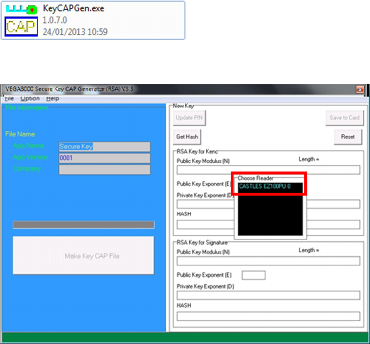
Run Secure Key Generator
Insert Key Card and select smart card reader
Enter Key Card PIN, default PIN is “1234”.
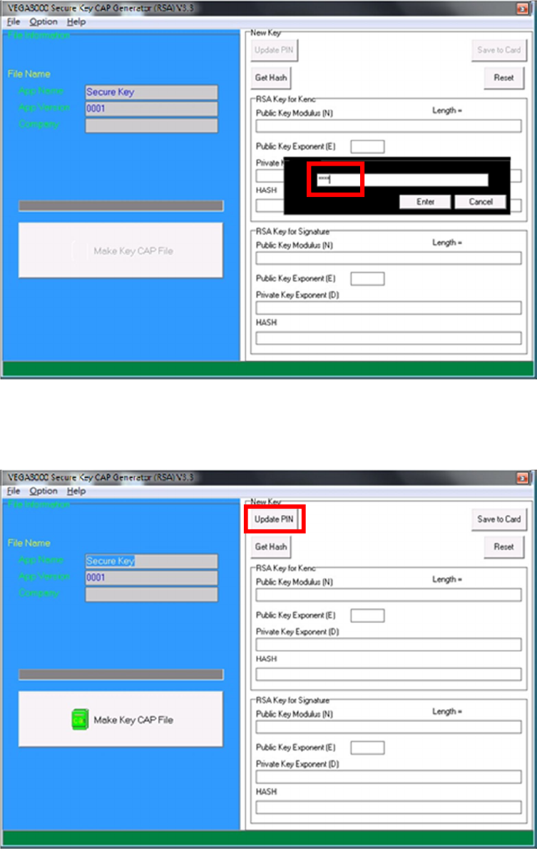
Castles Technology Co., Ltd. Confidential • All Right Reserved. Pg. 45
To change Key Card PIN, press “Update PIN” button. If not, please skip this
steps.
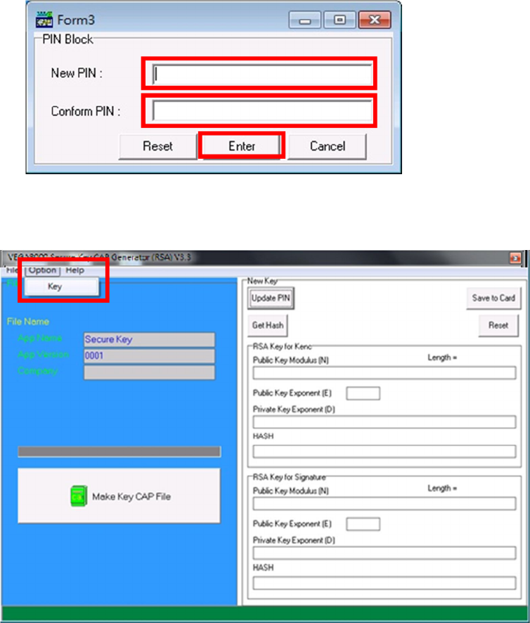
Enter new PIN, enter new PIN again to confirm, then press [Enter] button
to change PIN in Key Card.
Castles Technology Co., Ltd. Confidential • All Right Reserved. Pg. 46
To view current key set hash value, goto “Option” and select key.
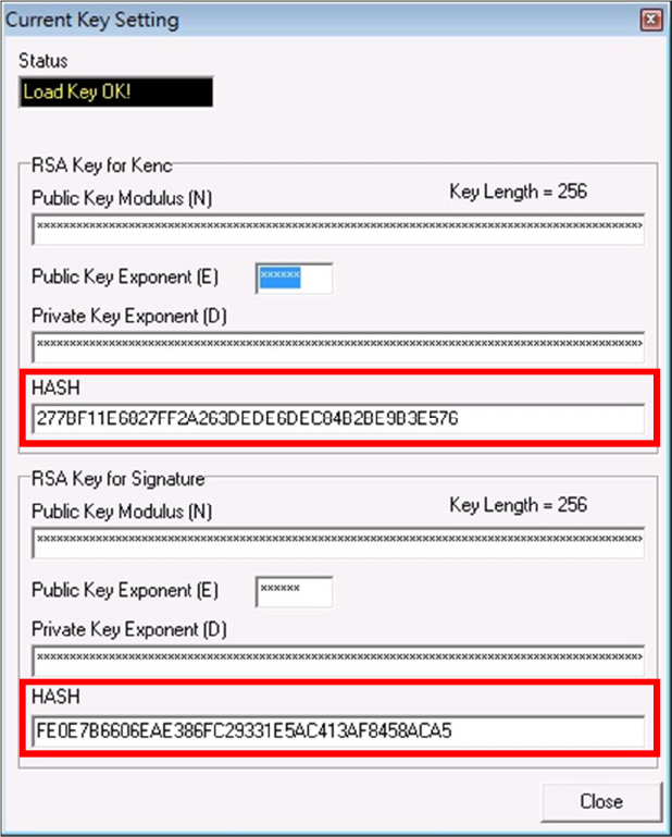
Castles Technology Co., Ltd. Confidential • All Right Reserved. Pg. 47
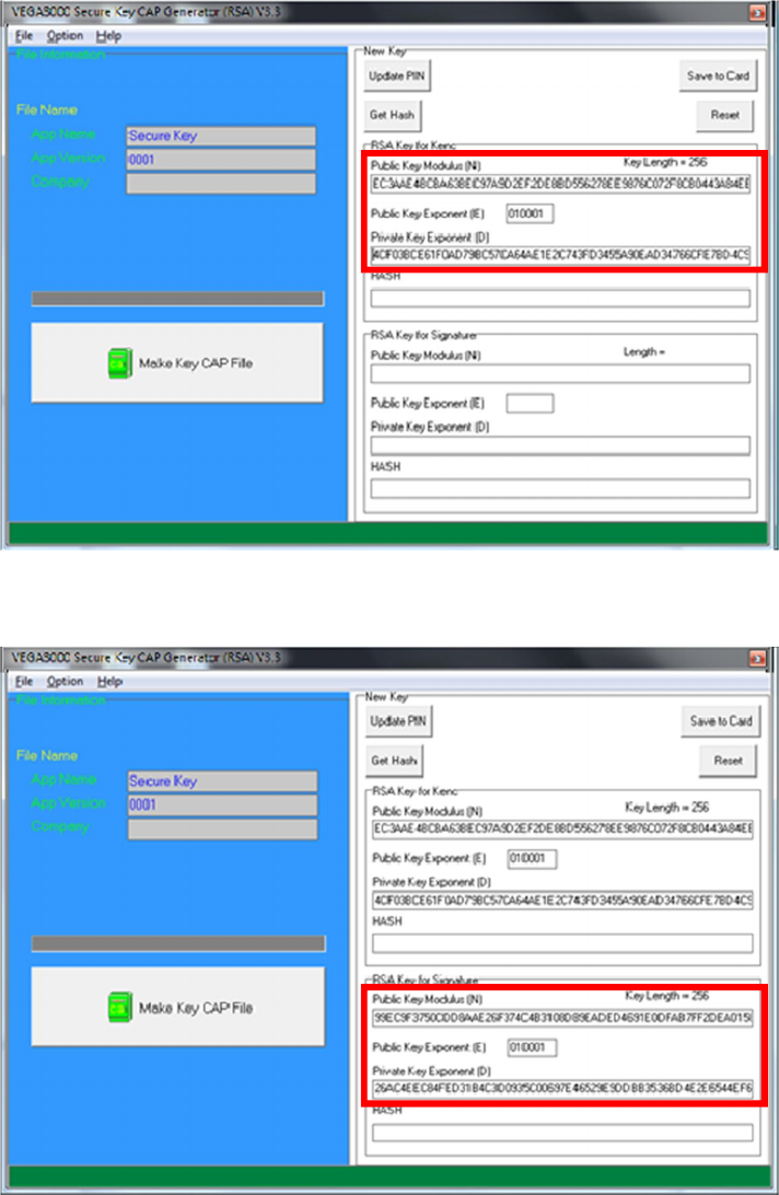
To generate new user key set
Please generate the RSA key by yourself,thelengthof the RSA key set
should be 2048 (bits).
Copy RSA key components to RSA Key for Kenc in Secure Key
Generator.
Castles Technology Co., Ltd. Confidential • All Right Reserved. Pg. 48
Generate second RSA key set for Signature.
Castles Technology Co., Ltd. Confidential • All Right Reserved. Pg. 49
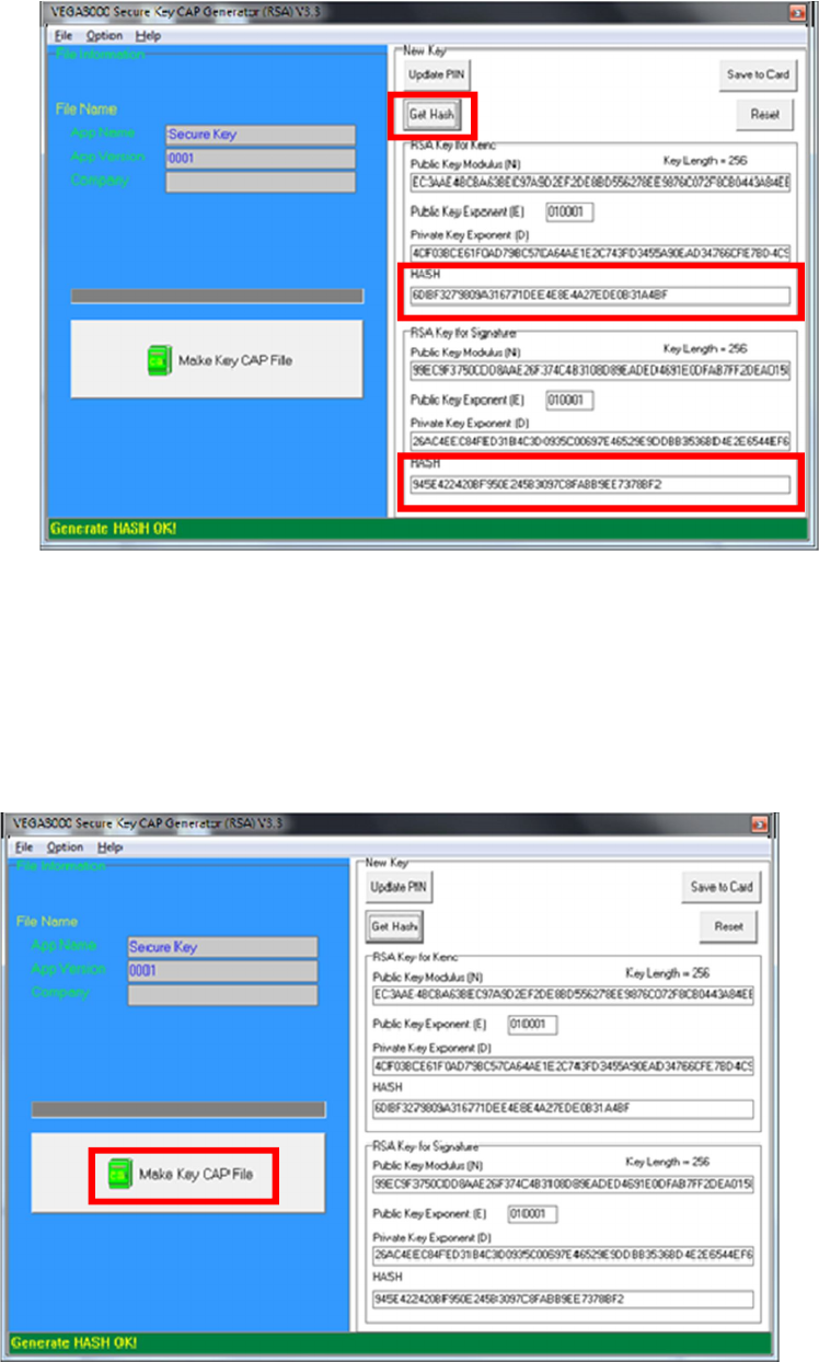
Click [Get Hash] button to calculate the hash value for key sets.
Please copy down all the values into a text file and keep in a safe place.
You will need this if you need to create duplicate Key Card.
To generate the key CAP for the newly generated user key set, press [Make
Key CAP File] button.
Castles Technology Co., Ltd. Confidential • All Right Reserved. Pg. 50
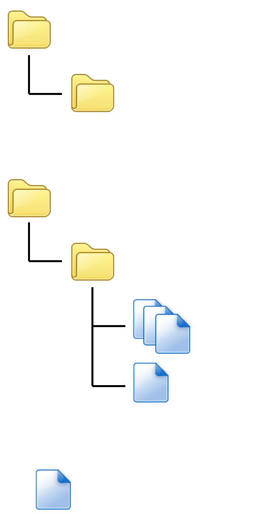
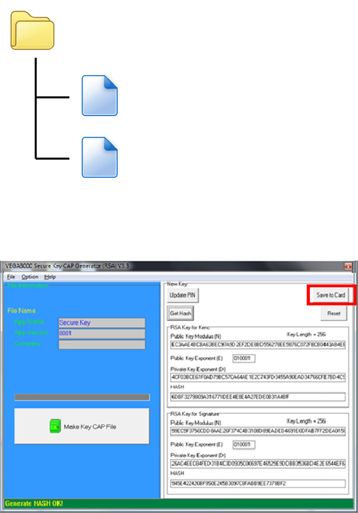
The output file will be located in the Secure Key Generator folder.
To update the newly generated key set to Key Card, press [Save to Card]
button to write the key set to Key Card.
SecureKeyGenerator
key.mci
key.cap
Castles Technology Co., Ltd. Confidential • All Right Reserved. Pg. 51
5. Font Management
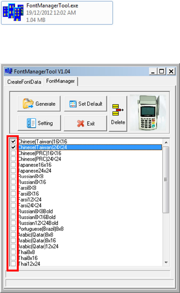
5.1. Loading New Font
Run FontManager.exe
Located at C:\Program Files\Castles\Font Manager
Select font to download
Castles Technology Co., Ltd. Confidential • All Right Reserved. Pg. 52
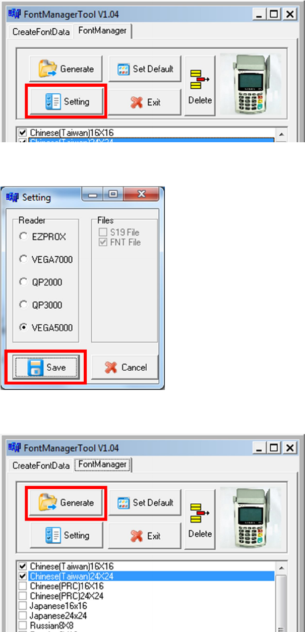
Press [Setting] button to configure the type.
Select VEGA5000, press [Save] button to save and return font manager.
Press [Generate] to create the font file.
Castles Technology Co., Ltd. Confidential • All Right Reserved. Pg. 53
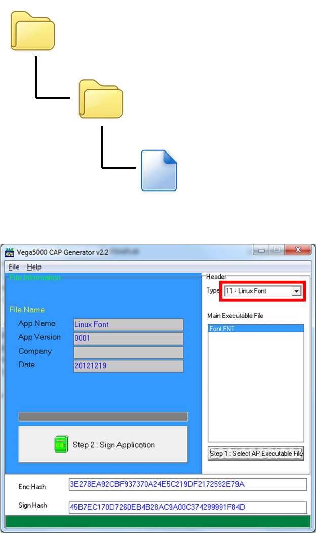
Output file “Font.FNT” will be located at sub-directory named “Font” in “Font
Manager” folder.
Sign the file using CAP Generator, the type must set to “11 – Linux Font”.
Lastly, download the signed file (CAP file) to UPT1000 using Loader.
Font Manager
Font
Font.FNT
Castles Technology Co., Ltd. Confidential • All Right Reserved. Pg. 54
5.2. Custom Font
User may create font they preferred for displaying or printing on UPT1000.
There are two zone defined:
Zone 0x00 ~ 0x7F – ASCII characters, you may replace with the font type
preferred or your own language character set.
Zone 0x80 ~ 0xFF – Free to use, you may use for symbols.
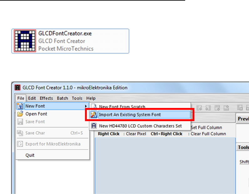
Following steps demonstrate how to create a 12x24 font.
Run GLCD Font Creator
Select [File] [New Font] [Import An Existing System Font]
Castles Technology Co., Ltd. Confidential • All Right Reserved. Pg. 55
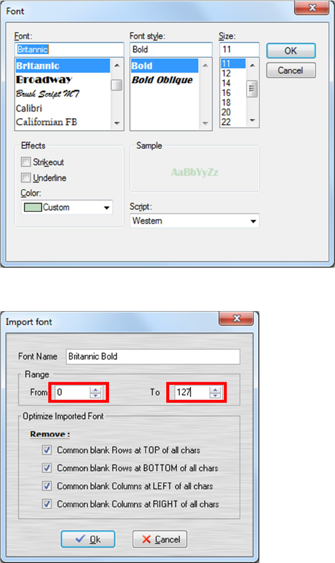
Select the font needed, simply choose a font size. The final value of font size
should be determine by the minimum pixel width. You may need to repeat this
steps few times to find the best fit font size.
Set the import range from 0 to 127.
Castles Technology Co., Ltd. Confidential • All Right Reserved. Pg. 56
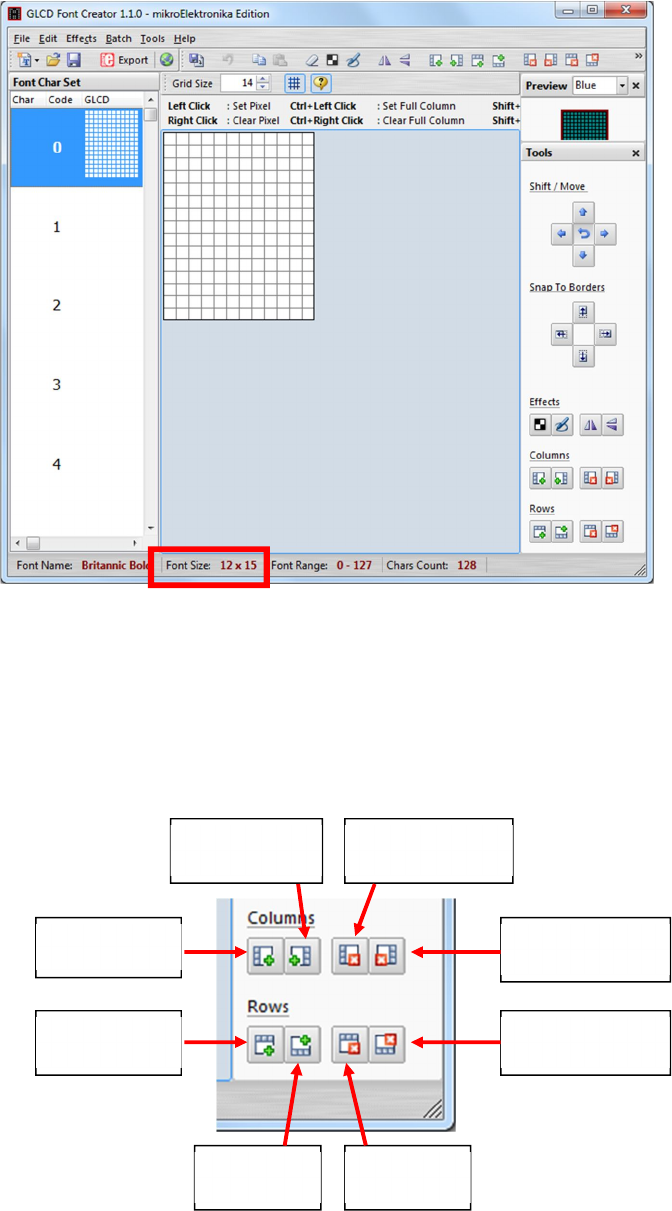
Check the minimum pixel width and height.
If the pixel width of the font size is larger than expected, then you have to
repeat the previous steps to import font with smaller size.
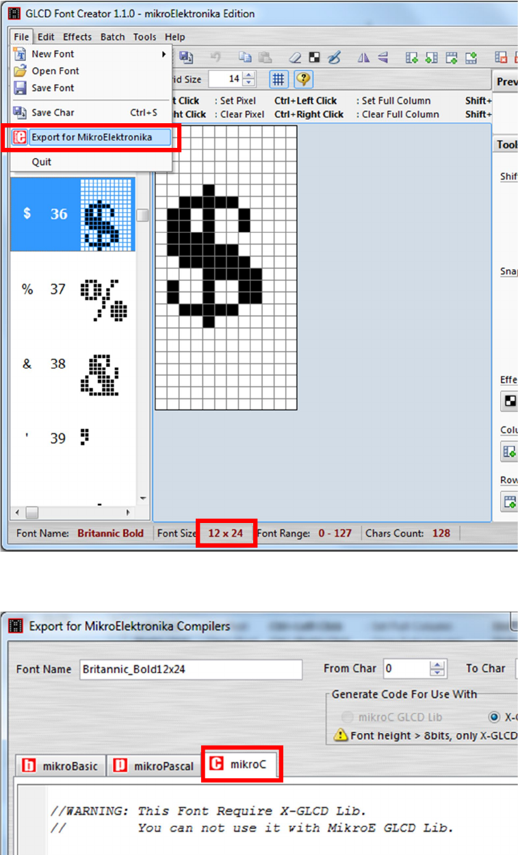
Use the following buttons to adjust the font size to match with expected font
size.
Add row on
top
Add row
on bottom
Remove
row on top
Remove row
on bottom
Add column
on
left
Add
columnonrigh
t
Removecolum
nonleft
Removecolumn
onright
Castles Technology Co., Ltd. Confidential • All Right Reserved. Pg. 57
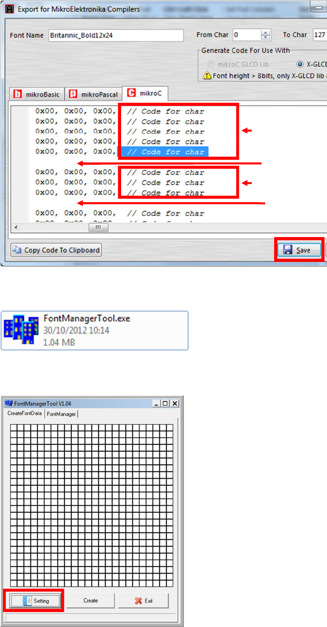
After adjust font size, select [File] [Export for MicroElektronika].
Select output format as [mikroC].
Castles Technology Co., Ltd. Confidential • All Right Reserved. Pg. 58
Remove comment “// Code for char “from offset 0x00 to 0x1F. Remove empty
line if found. Then click [Save] button to save to file.
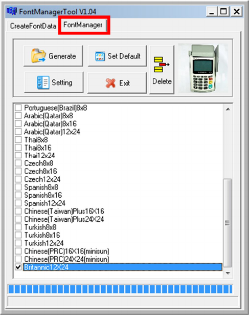
Run Font Manager Tool.
Click [Setting] button
Remove
Remove
Remove
Remove
Castles Technology Co., Ltd. Confidential • All Right Reserved. Pg. 59
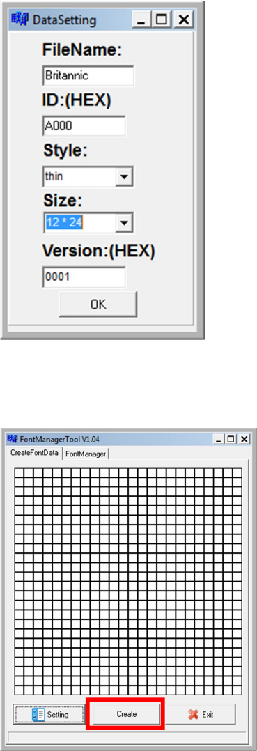
Enter the file name, font id, and select the size.
Click [Create] button, and select the C file previously created using GLCD
Font Generator.
Castles Technology Co., Ltd. Confidential • All Right Reserved. Pg. 60
Select [Font Manager] tab and tick the newly createdfont, and press
[Generate] button to export to FNT file.
Castles Technology Co., Ltd. Confidential • All Right Reserved. Pg. 61
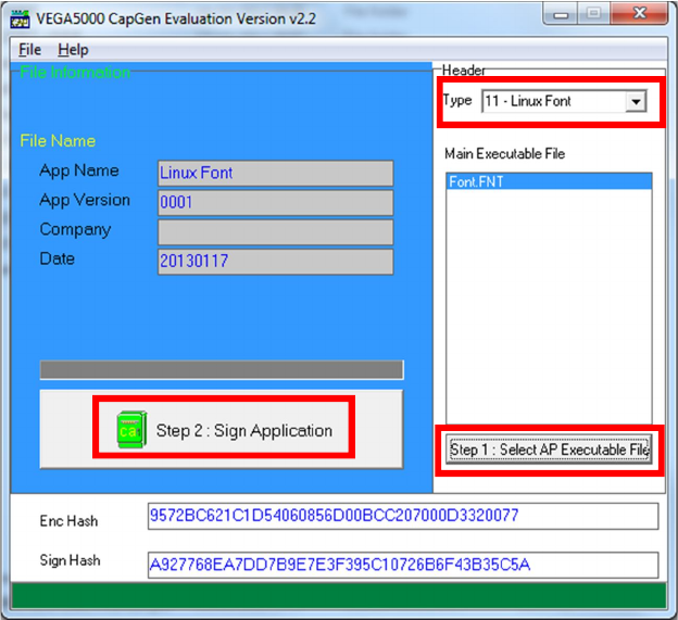
Use CAP Generator to convert the FNT file to CAP.
Set type to [11 – Linux Font], press [Step 1] button select the FNT file. Then
press [Step 2] to generate CAP file.
Download the font CAP file to UPT1000.
In the application, add following code to display message using the newly
created font.
CTOS_LanguageConfig(0xA000,d_FONT_12x24,0,d_FALSE);
CTOS_LanguageLCDSelectASCII(0xA000);
CTOS_LCDTPrintXY(1, 1, "ABCDEFGH");
Or print message using the newly created font.
CTOS_LanguagePrinterSelectASCII(0xA000);
CTOS_PrinterPutString("ABCDEFGH");
Castles Technology Co., Ltd. Confidential • All Right Reserved. Pg. 62
5.3. Using TrueType Font (TTF)
TrueType Font (TTF) is supported in UPT1000. You can download the TrueType
font to UPT1000 for displaying or printing.
Following steps demonstrate how to use “Cooper Black” TrueType font.
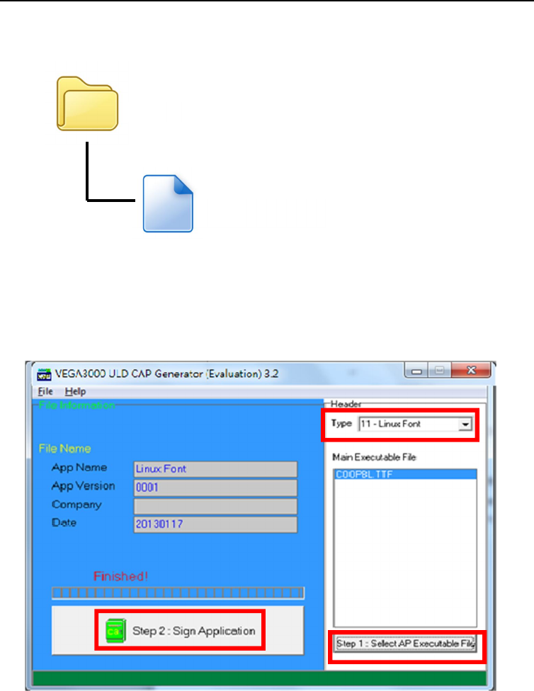
Copy the TTF file needed to an empty folder.
Use CAP Generator to convert the TTF file to CAP.
Set type to [11 – Linux Font], press [Step 1] button select the TTF file.
Then press [Step 2] to generate CAP file.
Download the font CAP file to UPT1000.
TTF
COOPBL.TTF
Castles Technology Co., Ltd. Confidential • All Right Reserved. Pg. 63
In the application, add following code to display message using the newly
added font.
CTOS_LCDTTFSelect("COOPBL.TTF", 0);
CTOS_LCDFontSelectMode(d_FONT_TTF_MODE);
CTOS_LCDTSelectFontSize(0x203C); // 32x60
CTOS_LCDTClearDisplay();
CTOS_LCDTPrintXY(1, 1, "Hello World");
Or print message using the newly added font.
CTOS_PrinterTTFSelect("COOPBL.TTF", 0);
CTOS_PrinterFontSelectMode(d_FONT_TTF_MODE);
CTOS_LanguagePrinterFontSize(0x203C, 0, 0); // 32x60
CTOS_PrinterPutString("Hello World");
Castles Technology Co., Ltd. Confidential • All Right Reserved. Pg. 64
6. Technical Notes
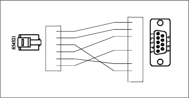
6.1. Serial Cable PIN Assignment
RJ12 6P6C
Male Plug
RS232
Female
1 ○
2 ○
3 ○
4 ○
5 ○
6 ○
○ 1
○ 2
○ 3
○ 4
○ 5
○ 6
○ 7
○ 8
○ 9
VCC
TXD
RTS
RXD
CTS
GND
VCC
RXD
TXD
GND
RTS
CTS

Castles Technology Co., Ltd. Confidential • All Right Reserved. Pg. 65
7. Appendix
7.1. Cautions
Federal Communication Commission Interference Statement
This device complies with Part 15 of the FCC Rules. Operation is subject to the following two
conditions: (1) This device may not cause harmful interference, and (2) this device must
accept any interference received, including interference that may cause undesired operation.
This equipment has been tested and found to comply with the limits for a Class B digital
device, pursuant to Part 15 of the FCC Rules. These limits are designed to provide
reasonable protection against harmful interference in a residential installation. This
equipment generates, uses and can radiate radio frequency energy and, if not installed and
used in accordance with the instructions, may cause harmful interference to radio
communications. However, there is no guarantee that interference will not occur in a
particular installation. If this equipment does cause harmful interference to radio or
television reception, which can be determined by turning the equipment off and on, the user
is encouraged to try to correct the interference by one of the following measures:
Reorient or relocate the receiving antenna.
Increase the separation between the equipment and receiver.
Connect the equipment into an outlet on a circuit different from that
to which the receiver is connected.
Consult the dealer or an experienced radio/TV technician for help.
FCC Caution:
Any changes or modifications not expressly approved by the party responsible for
compliance could void the user's authority to operate this equipment.
This transmitter must not be co-located or operating in conjunction with any other
antenna or transmitter.
Radiation Exposure Statement:
This equipment complies with FCC radiation exposure limits set forth for an uncontrolled
environment. This equipment should be installed and operated with minimum distance 20cm
between the radiator & your body.
Note: The country code selection is for non-US model only and is not available to all US
model. Per FCC regulation, all WiFi product marketed in US must fixed to US operation
channels only.
~ END ~