CASTLES TECHNOLOGY VEGA3000-UL PIN Pad User Manual VEGA5000 Book 2
CASTLES TECHNOLOGY CO., LTD. PIN Pad VEGA5000 Book 2
UserManual.wiki
>
CASTLES TECHNOLOGY
>
VEGA3000 UL User Manual
Users Manual
Navigation menu
Upload a User Manual
Namespaces
Wiki Guide
HTML
PDF
Info
Views
User Manual
Discussion / Help
Navigation
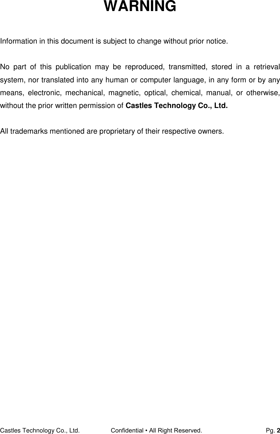
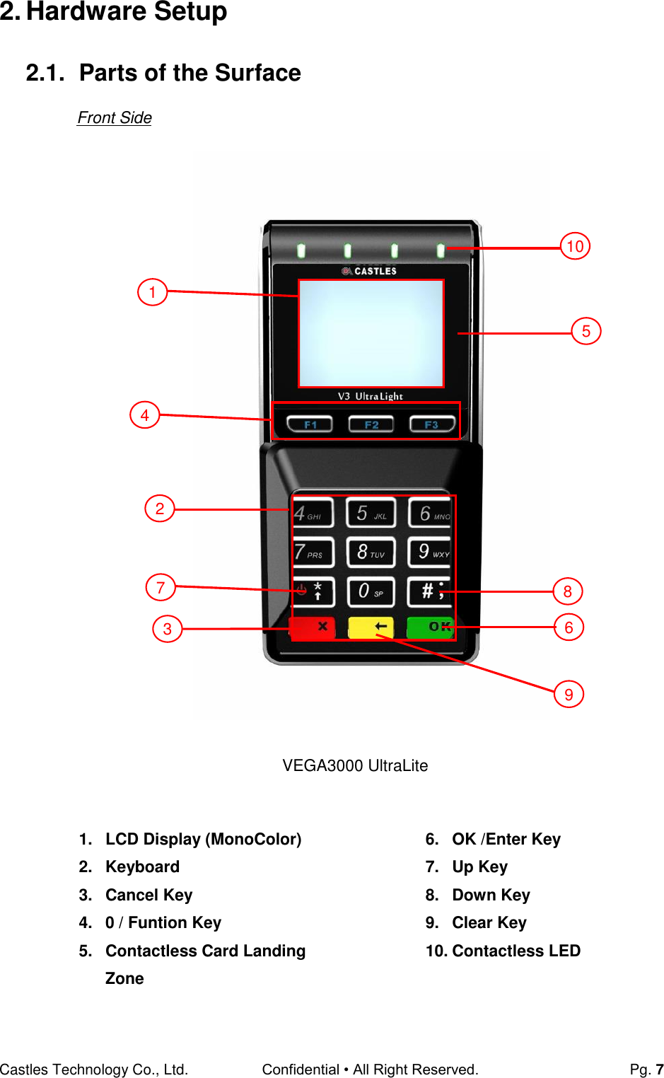

![Castles Technology Co., Ltd. Confidential • All Right Reserved. Pg. 10 3. Basic Operation 3.1. Program Manager Upon power on, terminal will enter Program Manager if not default application selected. All user applications are list in Program Manager. User may select an application and run the application or view the application info, delete the application or set to default run upon power on. User may enter System Menu to configure terminal settings. Program Manager Press[0] button to enter System Menu. Press [1] button to toggle default application selection. Press [2] button to delete application. Press [3] button to view application info. Press [OK] button to run application. Press [*] or [#] toup and down for applicationselection. System Menu Page 1 Press [#] button to page 2. Program Manager -----------01/02 1.App1 2.App2 0:Download System Menu 1.Download AP 2.System Info 3.Memory Status 4.Sys Settings 5.Test Utility 6.Factory Reset 7.Power Off](https://usermanual.wiki/CASTLES-TECHNOLOGY/VEGA3000-UL/User-Guide-3133917-Page-10.png)
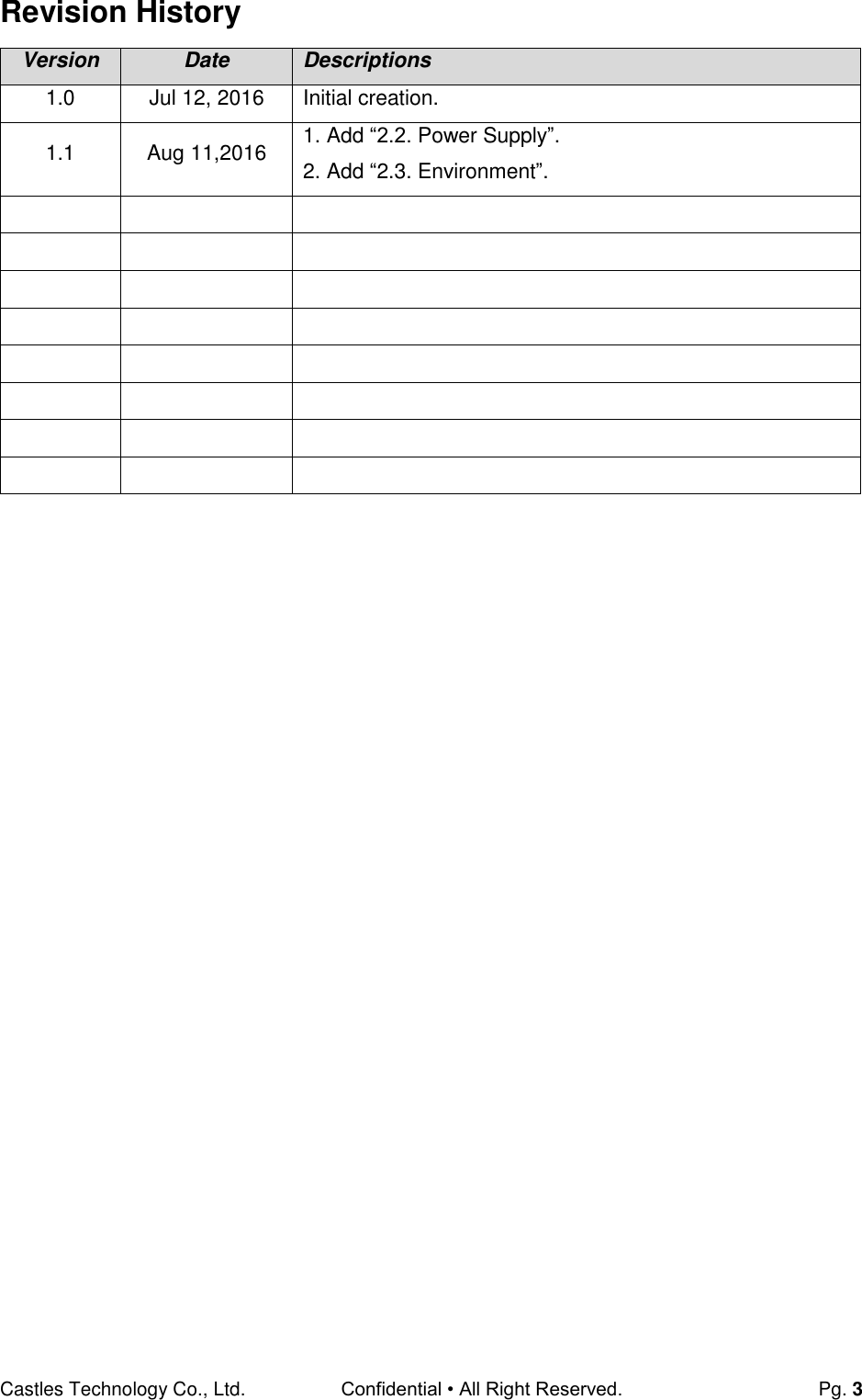
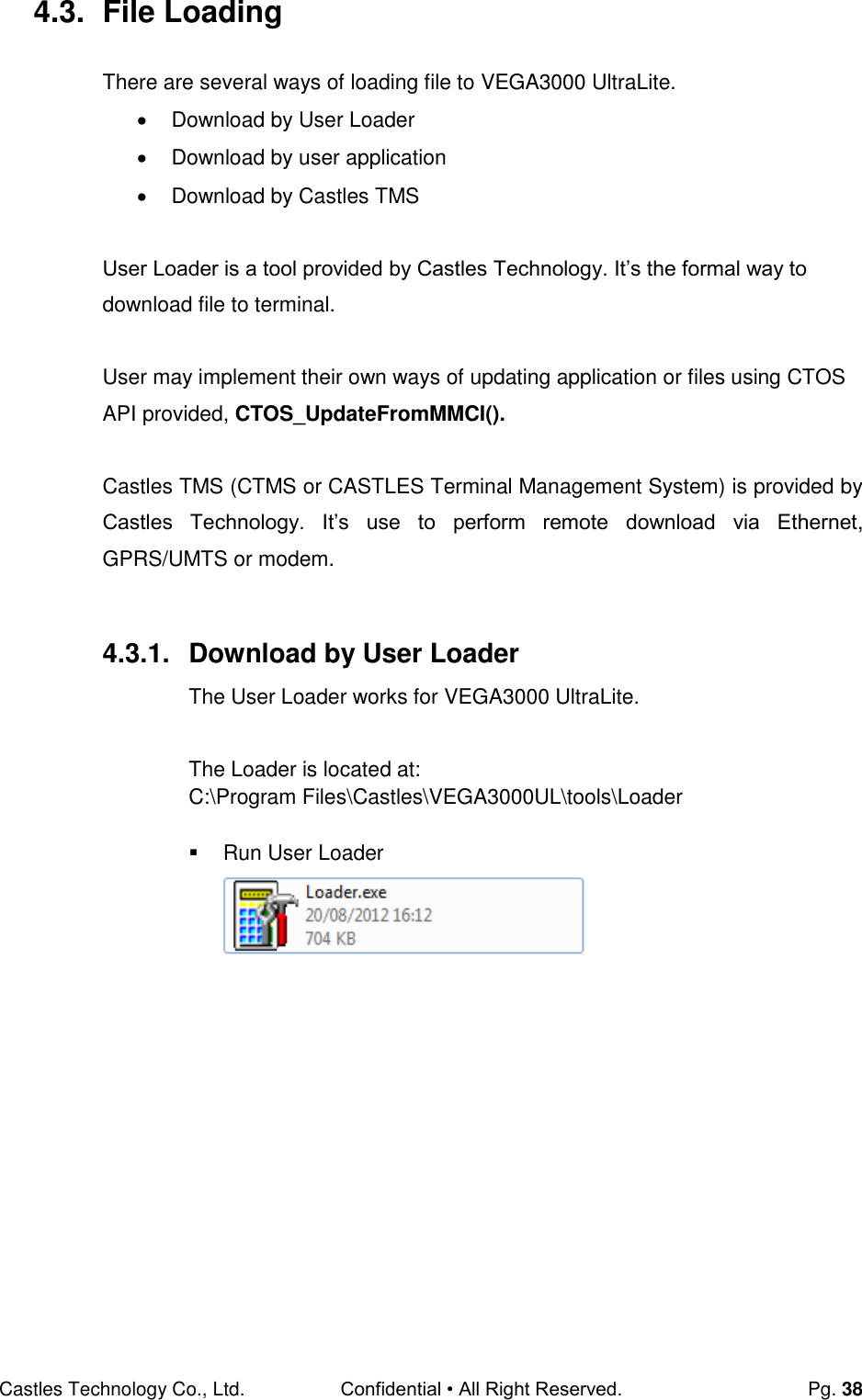
![Castles Technology Co., Ltd. Confidential • All Right Reserved. Pg. 11 Page 2 Press [*] button to page1. Press [#] button to page3. 3.2. Download AP Download user application or kernel modules firmware. System Menu Press [1] button to enter Download AP menu. Download AP Menu Select download source: Press [1] button to select source as RS232 or USB connection and enter ULD download mode. Press [2] button to select source as USB disk. System Menu 1.Download AP 2.System Info 3.Memory Status 4.Sys Settings 5.Test Utility 6.Factory Reset 7.Power Off Download EX 1.RS232 or USB 2.USB Disk 3.SD Card Select DW Source System Menu 1.PWD Change 2.ShareobjMng 3.FontMng4.ULD KEY HASH 5.Plug-in Mng 6.Key Injection 7.HW Detect](https://usermanual.wiki/CASTLES-TECHNOLOGY/VEGA3000-UL/User-Guide-3133917-Page-11.png)
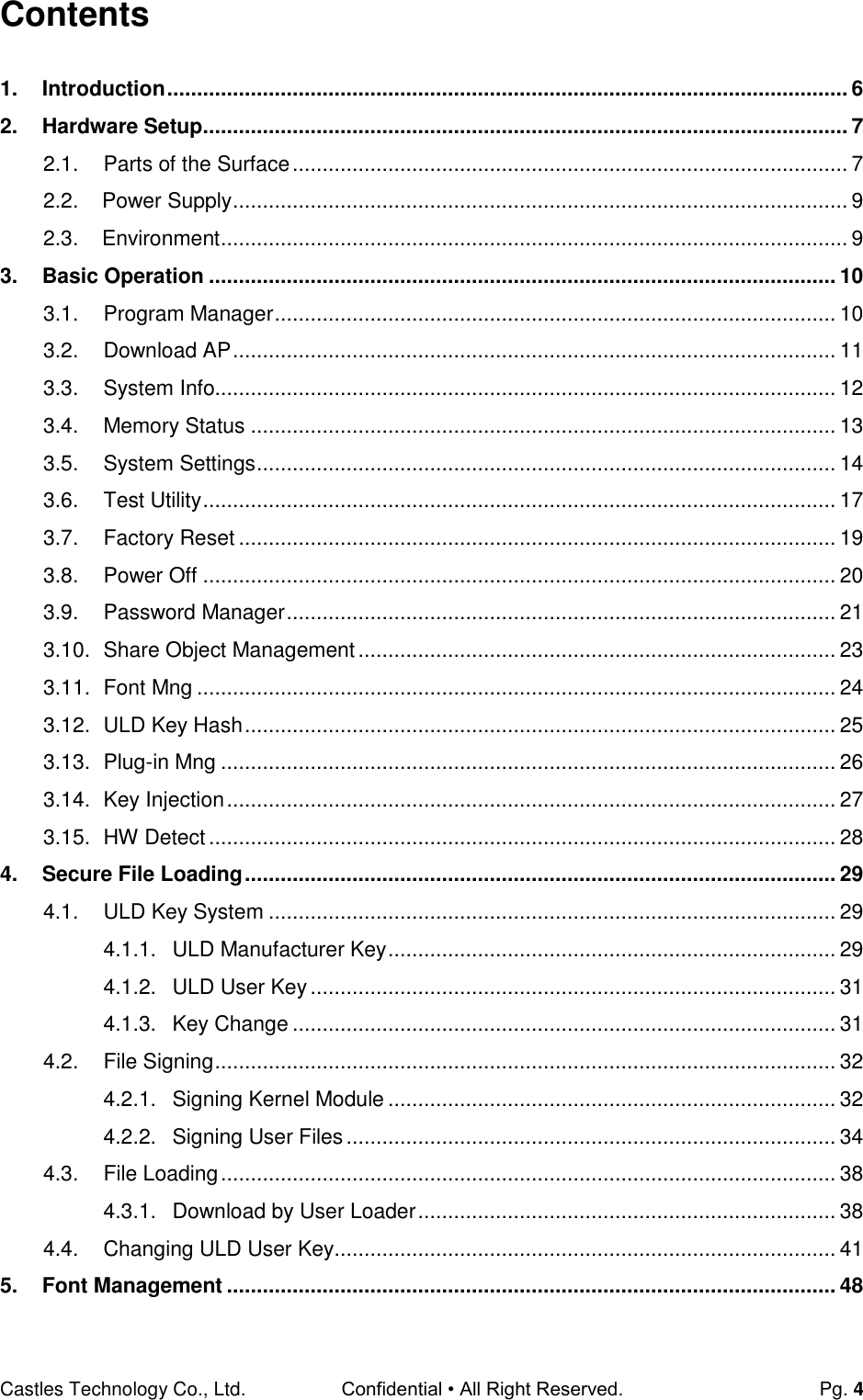
![Castles Technology Co., Ltd. Confidential • All Right Reserved. Pg. 12 Press [3] button to select source as SD card. 3.3. System Info View kernel module firmware information. System Menu Press [2] button to enter System Info menu. System Info Menu Page 1 Page 2 Page 3 Press [#] button to next page. Page 4 Page 5 Page 6 Page 8 Page9 Page 10 System Menu 1.Download AP 2.System Info 3.Memory Status 4.Sys Settings 5.Test Utility 6.Factory Reset 7.Power Off SYSTEM INFO ---Kernel Ver--- BIOS:VR0010 SULD :VRF810 LINUXKNL:VR0019 ROOTFS:VR9201 PEDST :VR0025 SYSTEM INFO --- KOVer --- SECURITY:VR0025 KMS :VR0024 DRV:VR0039 USB:N/A CIF:VR9020 SAM :VR9131 SYSTEM INFO --- SO Ver3 --- GSM:VR0018 BARCODE :VR0013 TMS:VR0013 TLS :VR0011 CLVW :VR0018 CTOSAPI :VR9029 SYSTEM INFO --- HWMVer --- CRDL/ETHE:ONCHIP CLM-MP : N/A --- APVer --- ULDPM :VR0026 SYSTEM INFO HUSBID:0CA6A050 CUSBID:N/A --Factory S/N--- FFFFFFFFFFFFFFFF CAEMVL2 :VR9113 CAEMVL2AP :VR0005 SYSTEM INFO --- KOVer2 --- CL:VR0018 SC :VR0011 SYSTEM INFO --- SOVer--- UART :VR0014 USBH :VR0011 MODEM :VR0014 ETHERNET:VR0029 FONT :VR0025 LCD :VR0034 SYSTEM INFO --- SO Ver2 --- PRT:VR0020 RTC :VR0013 ULDPM :VR0022 PPPMODEM:VR0026 KMS:VR0022 FS:VR0015 SYSTEM INFO --EXT SO Ver P.1-- CACLMDL :VR0007 CACLENTRY :VR0007 CAMPP :VR0006 CAVPW :VR0018 CAAEP :VR0004 CAJCT :VR9407](https://usermanual.wiki/CASTLES-TECHNOLOGY/VEGA3000-UL/User-Guide-3133917-Page-12.png)
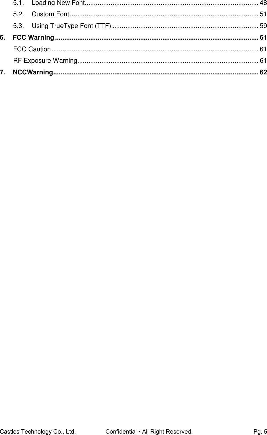
![Castles Technology Co., Ltd. Confidential • All Right Reserved. Pg. 13 Page 11 3.4. Memory Status View terminal flash memory and RAM information. System Menu Press [3] button to enter Memory Status menu. Memory Status Menu System Menu 1.Download AP 2.System Info 3.Memory Status 4.Sys Settings 5.Test Utility 6.Factory Reset 7.Power Off MEMORY STATUS --FLASH Memory-- Total: 130688KB Used :52404KB --SDRAM Memory-- Total: 65408KB Used :38004KB SYSTEM INFO --EXT SO Ver P.1-- CAVAP:VR0002 CACQP:VR6601 CAIFH :VR0002 CAEMVL2 :VRA016 CAEMVL2AP :VR0009](https://usermanual.wiki/CASTLES-TECHNOLOGY/VEGA3000-UL/User-Guide-3133917-Page-13.png)
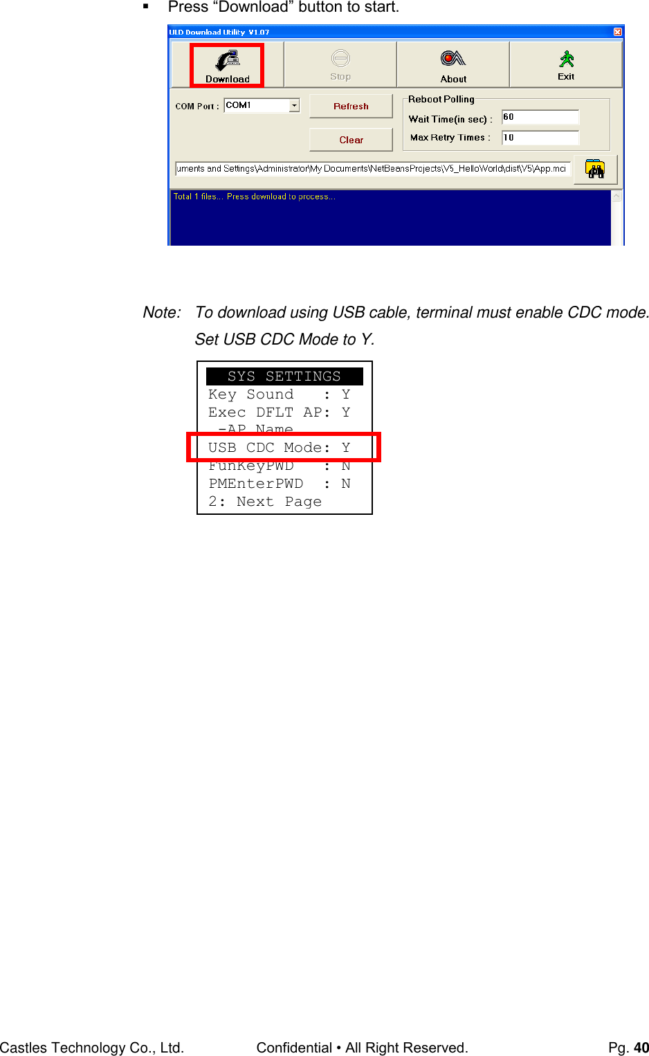
![Castles Technology Co., Ltd. Confidential • All Right Reserved. Pg. 14 3.5. System Settings View or change terminal system settings. Setting Descriptions Key Sound Enable (Y) or disable (N) the beep sound when pressing any key. Exec DFLT AP Enable (Y) or disable (N) execution of default selected application. USB CDC Mode Enable (Y) or disable (N) USB CDC mode. FunKey PWD Enable (Y) or disable (N) password protection to access function key (0, F1, F2, F3) in Program Manager. PMEnter PWD Enable (Y) or disable (N) password protection to enter Program Manager. SET USB Host Enable (Y) or disable (N) USB host mode. Base USB CDC Enable (Y) or disable (N) USB CDC mode in base unit. [Portable model only] List SHR Lib Enable (Y) or disable (N) to list all shared libraries in Program Manager. Key MNG Mode <TBC> BATThreshld Battery charging threshold value. [Portable model only] Null Cradle Enable (Y) if base is Type Acradle. [Portable model only] Debug Mode Enable (Y) or disable (N) console debug mode. Debug Port Serial port for console debug. Mobil AutoON Enable (Y) or disable (N) to auto turn on GSM module after start up the terminal. Bklit Auto Off Enable (Y) or disable (N) Auto OffLCDBacklight Bklit Off Time Thresholdof Auto Off LCD Backlight PWR KEY OFF Powerkeyfunction, power off (Y) or reboot(N) RTC Time Zone Set Time Zone of Real Time Clock. NTP Enable Enable (Y) or disable (N) Network Time Protocol. NTP Update Freq Frequency of Network Time Protocol updating. BT DIRECT ACCESS Enable (Y) or disable (N) Bluetooth direct access mode.](https://usermanual.wiki/CASTLES-TECHNOLOGY/VEGA3000-UL/User-Guide-3133917-Page-14.png)
![Castles Technology Co., Ltd. Confidential • All Right Reserved. Pg. 15 Halt Timeout Set timeout for AP to back to Program Manager whenever AP is in halt state. PWM Auto Enable (Y) or disable (N) power saving mode. PWM Mode Select (STB) standby mode or (SLP) sleep mode for power saving mode. PWM Time Set time period by which to make terminal getting into power saving mode from idle state. Auto Reboot Terminal will reboot in specific time every day. Reboot Hour The specific hour of day for Auto Reboot. Reboot Min The specific minuteof day for Auto Reboot. System Menu Press [4] button to enter System Settings menu. System Settings Menu Page 1Page 2 Page 3 Page 4 System Menu 1.Download AP 2.System Info 3.Memory Status 4.Sys Settings 5.Test Utility 6.Factory Reset 7.Power Off SYS SETTINGS Key Sound : Y Exec DFLT AP : Y -Default AP Name USB CDC Mode : Y FunKeyPWD:N PMEnterPWD:N 2: Next Page SYS SETTINGS SET USB Host: N Base USB CDC: X List SHR Lib: N Key MNG Mode: 0 Bat Threshld: X Null Cradle : X 1: Prev2: Next SYS SETTINGS Debug Mode: N Debug Port : X Mobil AutoON: N Bklit Auto Off : N BklitOff Time : X PWR KEY OFF :N 1: Prev2: Next SYS SETTINGS RTC Time Zon:GMT NTP Enable:N NTP Update F:X 1: Prev2: Next](https://usermanual.wiki/CASTLES-TECHNOLOGY/VEGA3000-UL/User-Guide-3133917-Page-15.png)
![Castles Technology Co., Ltd. Confidential • All Right Reserved. Pg. 16 Page 5Page 6 Press [*] or [#]button to select setting. Press [OK] button to change the setting value. Press [] button to toggle Y N Y. Press [1] button to previous page. Press [2] button to next page. SYS SETTINGS BT DIRECT ACCESS :X Halt Timeout :999 PWM Auto :N PWM Mode : X PWM Time 1: Prev2: Next SYS SETTINGS Auto Reboot :Y Reboot Hour:00 Reboot Min :00 1: Prev Page](https://usermanual.wiki/CASTLES-TECHNOLOGY/VEGA3000-UL/User-Guide-3133917-Page-16.png)
![Castles Technology Co., Ltd. Confidential • All Right Reserved. Pg. 17 3.6. Test Utility Perform terminal hardware components diagnosis. System Menu Press [5] button to enter Test Utility menu. Test Utility Menu Page 1 Press [1] and [OK] to diagnose LCD. Press [2] and [OK] to diagnose keyboard. Press [3] and [OK] to diagnose flash memory. Press [4] and [OK] to diagnose smart card module. Press [5] and [OK] to diagnose backlight. Press [6] and [OK] to diagnose magnetic stripe card reader. Press [#] button to page 2. Page 2 System Menu 1.Download AP 2.System Info 3.Memory Status 4.Sys Settings 5.Test Utility 6.Factory Reset 7.Power Off Main Menu 0023 1.LCD 2.Keyboard 3.Flash 4.Smart Card 5.Backlight 6.MSR -> 1/3 Main Menu 0023 7.LED 8.RTC 9.Printer 10.Font 11.CL Transparent 12.CL Card Test -> 2/3](https://usermanual.wiki/CASTLES-TECHNOLOGY/VEGA3000-UL/User-Guide-3133917-Page-17.png)
![Castles Technology Co., Ltd. Confidential • All Right Reserved. Pg. 18 Press[7] and [OK] to diagnose LED. Press [8] and [OK] to diagnose RTC. Press [9] and [OK] to check Printer. Press [10] and [OK] to check FONT file in VEGA3000 UltraLite. Press [11] and [OK] to check CL transparent. Press [12] and [OK] to test Cantactless Card. Press [*] button to page 1. Press [#] button to page 3. Page 2 Press [13] and [OK] to execute SD Card Test. Press [14] and [OK] to testfunctionalityofWiFi. Press [15] and [OK] to test functionality of power saving. Press [16] and [OK] to test functionality of multiple communication ways.\ Press [17] and [OK] to testfunctionality of Bluetooth. Press [*] button to page2. Main Menu 0023 13.SD Card Test 14.Wi-Fi Test 15.Power Saving 16.Comm Menu 17.BT Test -> 3/3](https://usermanual.wiki/CASTLES-TECHNOLOGY/VEGA3000-UL/User-Guide-3133917-Page-18.png)
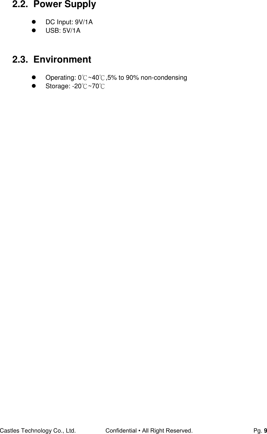
![Castles Technology Co., Ltd. Confidential • All Right Reserved. Pg. 19 3.7. Factory Reset Perform factory reset, all user application, fonts and data will be deleted. System Menu Press [6] button to enter Factory Reset menu. Enter password and press [OK]. Enter factory reset password.(Default password: 12345678) Enter new password. Enter new password again to confirm. System Menu 1.Download AP 2.System Info 3.Memory Status 4.Sys Settings 5.Test Utility 6.Factory Reset 7.Power Off FacRestPassword New Password: ******** Confirm Password ******** FacRest Password Enter Password: ******** Factory Reset OK to reset?](https://usermanual.wiki/CASTLES-TECHNOLOGY/VEGA3000-UL/User-Guide-3133917-Page-19.png)
![Castles Technology Co., Ltd. Confidential • All Right Reserved. Pg. 20 Press [OK] to execute the Factory Reset. 3.8. Power Off Power offterminal. System Menu Press [7] button to power off terminal. System Menu 1.Download AP 2.System Info 3.Memory Status 4.Sys Settings 5.Test Utility 6.Factory Reset 7.Power Off](https://usermanual.wiki/CASTLES-TECHNOLOGY/VEGA3000-UL/User-Guide-3133917-Page-20.png)
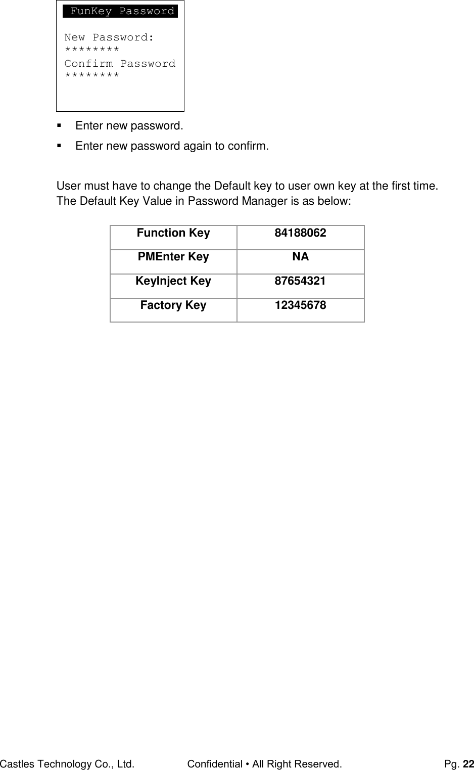
![Castles Technology Co., Ltd. Confidential • All Right Reserved. Pg. 21 3.9. Password Manager Change thekeysin Password Manager. System Menu (Page 2) Press [1] button to enterPasswordManagermenu. Press [1] button to changeFunction Key password. Press [2] button to change Program Manager Key password. Press [3] button to change Key Injection Key password. Press [4] button to change Factory Reset Key password. Please refer to the procedure of change Function Key password as below. Enter current password. (Default password is "84188062") FunKey Password Enter Password: ******** System Menu 1.PWDManager 2.ShareobjMng 3.FontMng4.ULD KEY HASH 5.Plug-in Mng 6.Key Injection 7.HW Detect Password Manager 1.Function Key 2.PMEnter Key 3.KeyInject Key 4.Factory Key](https://usermanual.wiki/CASTLES-TECHNOLOGY/VEGA3000-UL/User-Guide-3133917-Page-21.png)
![Castles Technology Co., Ltd. Confidential • All Right Reserved. Pg. 23 3.10. Share Object Management View share object in terminal. System Menu (Page 2) Press [2] button to enter Share Object Management menu. Share Object Management Menu Press [1] button to view shared library. Press [2] button to view shared file. Share objMng 1.Share LIB 2.Share File System Menu 1.PWD Change 2.ShareobjMng 3.FontMng4.ULD KEY HASH 5.Plug-in Mng 6.Key Injection 7.HW Detect](https://usermanual.wiki/CASTLES-TECHNOLOGY/VEGA3000-UL/User-Guide-3133917-Page-23.png)
![Castles Technology Co., Ltd. Confidential • All Right Reserved. Pg. 24 3.11. Font Mng View Font Management. System Menu (Page 2) Press [3] button to view Font Management. FontManagment Press [1] button to view FNT Font list. Press [2] button to view TTF Font list. Font Mng 1.FNT File 2.TTF File System Menu 1.PWD Change 2.ShareobjMng 3.FontMng4.ULD KEY HASH 5.Plug-in Mng 6.Key Injection 7.HW Detect](https://usermanual.wiki/CASTLES-TECHNOLOGY/VEGA3000-UL/User-Guide-3133917-Page-24.png)
![Castles Technology Co., Ltd. Confidential • All Right Reserved. Pg. 25 3.12. ULD Key Hash View ULD user key hash value. System Menu (Page 2) Press [4] button to view hash value. USER ENV KEY DA9C91FE668DF4B6D637CDBCCEC201444AA2C7FF USER SIGN KEY D52F36A1B569B5ABBA4FEAEFB34BEC000101D58C System Menu 1.PWD Change 2.ShareobjMng 3.FontMng4.ULD KEY HASH 5.Plug-in Mng 6.Key Injection 7.HW Detect](https://usermanual.wiki/CASTLES-TECHNOLOGY/VEGA3000-UL/User-Guide-3133917-Page-25.png)
![Castles Technology Co., Ltd. Confidential • All Right Reserved. Pg. 26 3.13. Plug-in Mng View Plug-in Management. System Menu (Page 2) Press [5] button to view Plug-in Management. Press [*]or[#]button to select item. Press [1]button to get item information. Press [2]button to delete item. Plug-in Mng 1.Info 2.Del System Menu 1.PWD Change 2.ShareobjMng 3.FontMng4.ULD KEY HASH 5.Plug-in Mng 6.Key Injection 7.HW Detect](https://usermanual.wiki/CASTLES-TECHNOLOGY/VEGA3000-UL/User-Guide-3133917-Page-26.png)
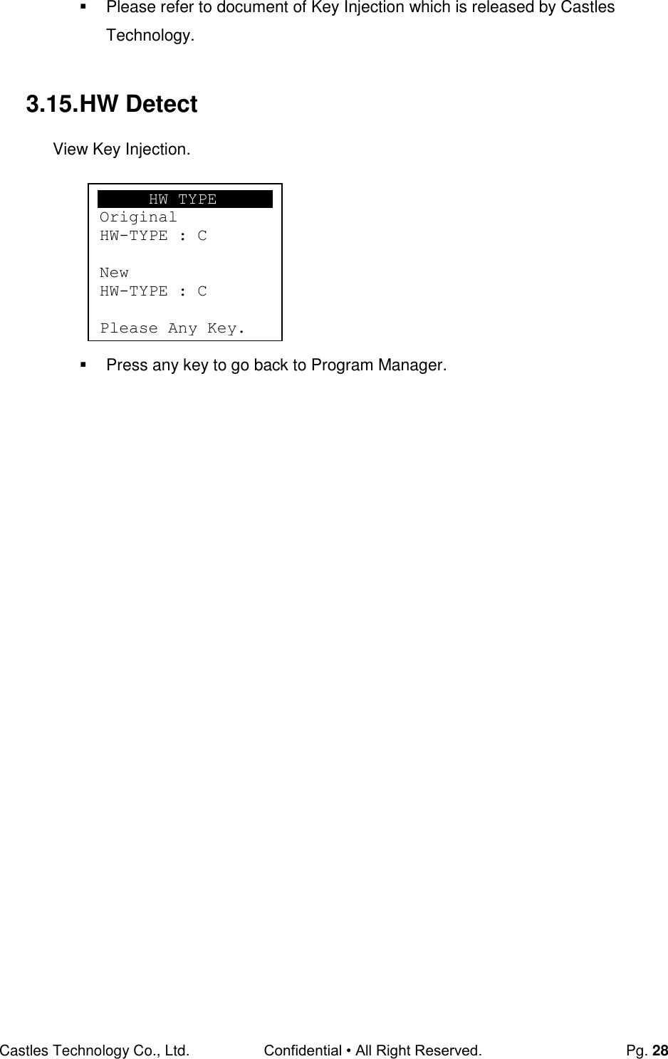
![Castles Technology Co., Ltd. Confidential • All Right Reserved. Pg. 27 3.14. Key Injection View Key Injection. System Menu (Page 2) Press [6] button to view Key Injection. Enter password and press [OK]. Enter Key Injection password.(Default password: 87654321) Enter new password. Enter new password again to confirm. System Menu 1.PWD Change 2.ShareobjMng 3.FontMng4.ULD KEY HASH 5.Plug-in Mng 6.Key Injection 7.HW Detect KeyInj Password New Password: ******** Confirm Password ******** KeyInjPassword Enter Password: ******** Key Injection Waiting for Command](https://usermanual.wiki/CASTLES-TECHNOLOGY/VEGA3000-UL/User-Guide-3133917-Page-27.png)
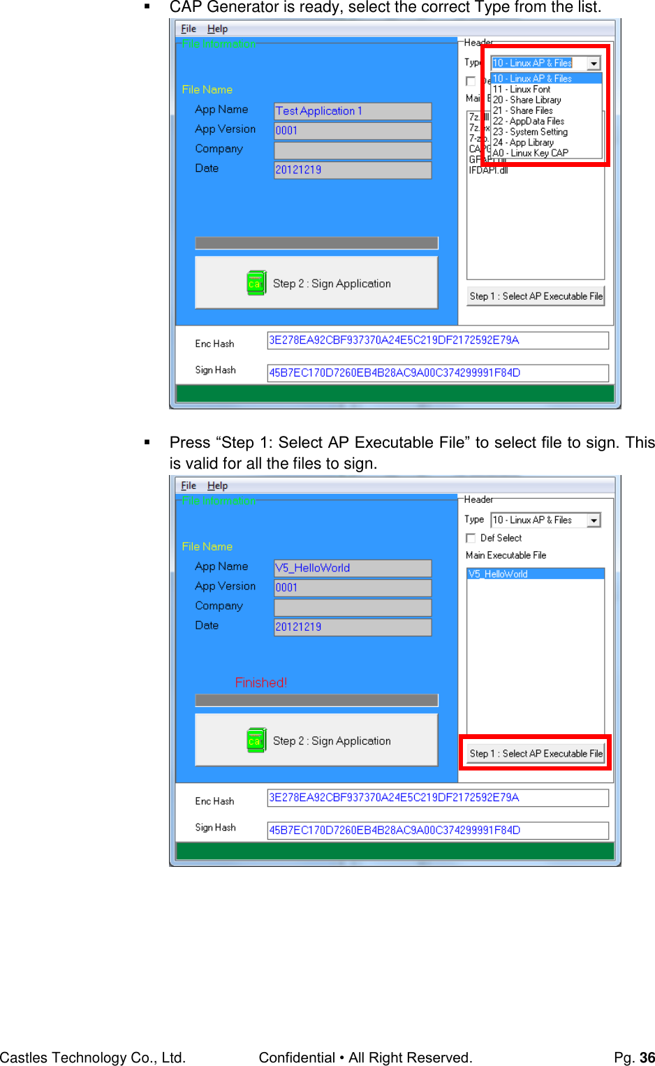
![Castles Technology Co., Ltd. Confidential • All Right Reserved. Pg. 39 Select COM port Browse and select mci file or mmci file Setup terminal to enter download mode Press [0] button in Program Manager (PM) Press [1] button to select “1. Download AP“ Press [1] button again to select download via RS232 or USB](https://usermanual.wiki/CASTLES-TECHNOLOGY/VEGA3000-UL/User-Guide-3133917-Page-39.png)
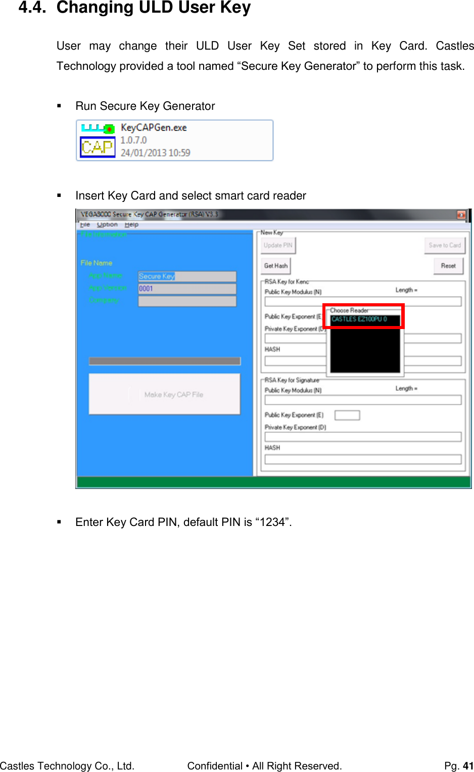
![Castles Technology Co., Ltd. Confidential • All Right Reserved. Pg. 42 To change Key Card PIN, press “Update PIN” button. If not, please skip this steps. Enter new PIN, enter new PIN again to confirm, then press [Enter] button to change PIN in Key Card.](https://usermanual.wiki/CASTLES-TECHNOLOGY/VEGA3000-UL/User-Guide-3133917-Page-42.png)
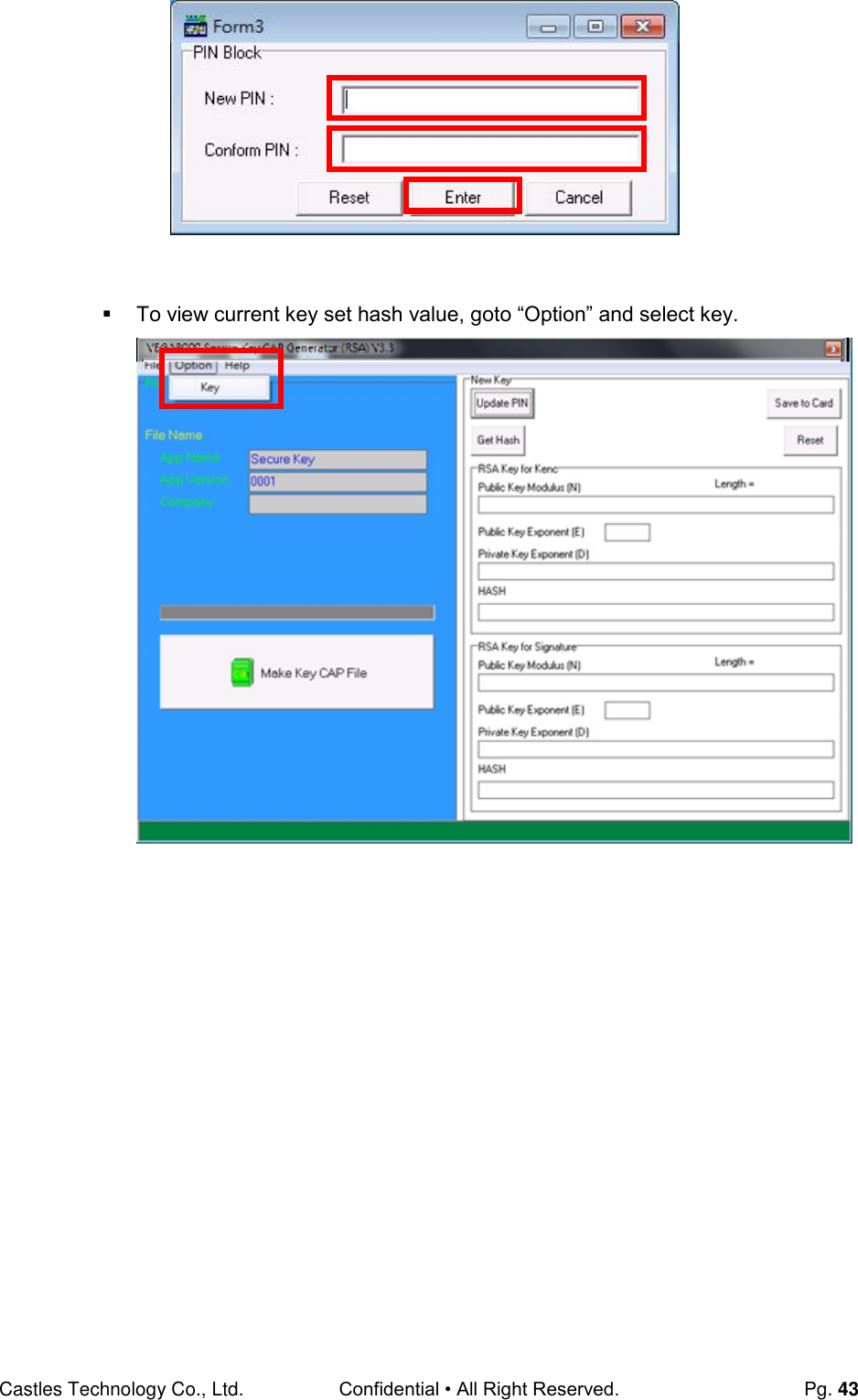
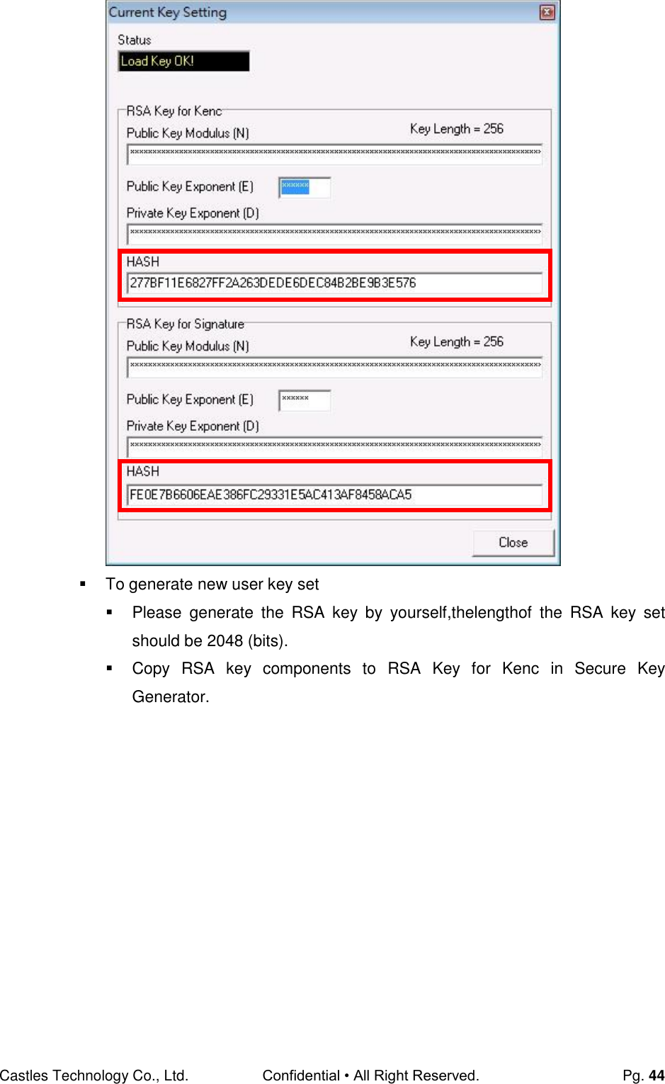
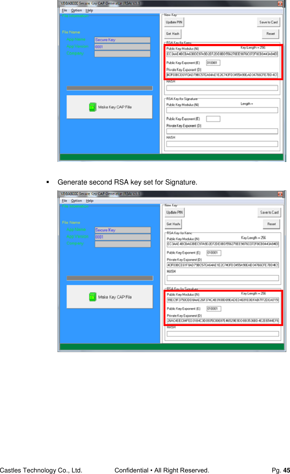
![Castles Technology Co., Ltd. Confidential • All Right Reserved. Pg. 46 Click [Get Hash] button to calculate the hash value for key sets. Please copy down all the values into a text file and keep in a safe place. You will need this if you need to create duplicate Key Card. To generate the key CAP for the newly generated user key set, press [Make Key CAP File] button.](https://usermanual.wiki/CASTLES-TECHNOLOGY/VEGA3000-UL/User-Guide-3133917-Page-46.png)
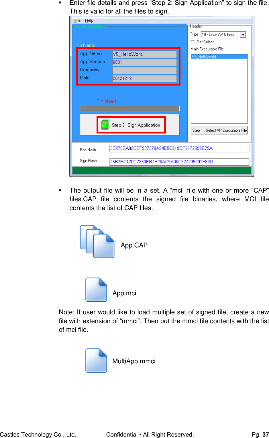
![Castles Technology Co., Ltd. Confidential • All Right Reserved. Pg. 47 The output file will be located in the Secure Key Generator folder. To update the newly generated key set to Key Card, press [Save to Card] button to write the key set to Key Card. SecureKeyGenerator key.mci key.cap](https://usermanual.wiki/CASTLES-TECHNOLOGY/VEGA3000-UL/User-Guide-3133917-Page-47.png)
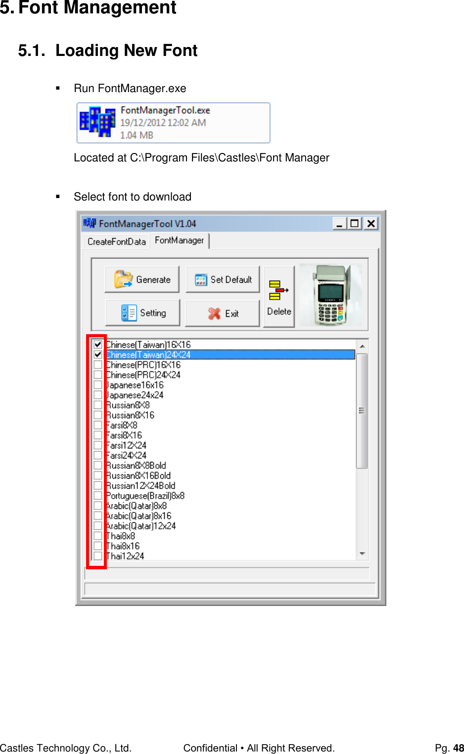
![Castles Technology Co., Ltd. Confidential • All Right Reserved. Pg. 49 Press [Setting] button to configure terminal type. Select VEGA5000, press [Save] button to save and return font manager. Press [Generate] to create the font file.](https://usermanual.wiki/CASTLES-TECHNOLOGY/VEGA3000-UL/User-Guide-3133917-Page-49.png)
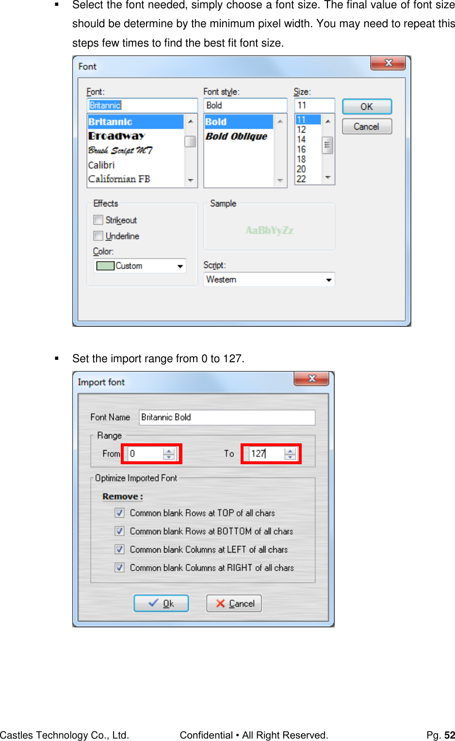
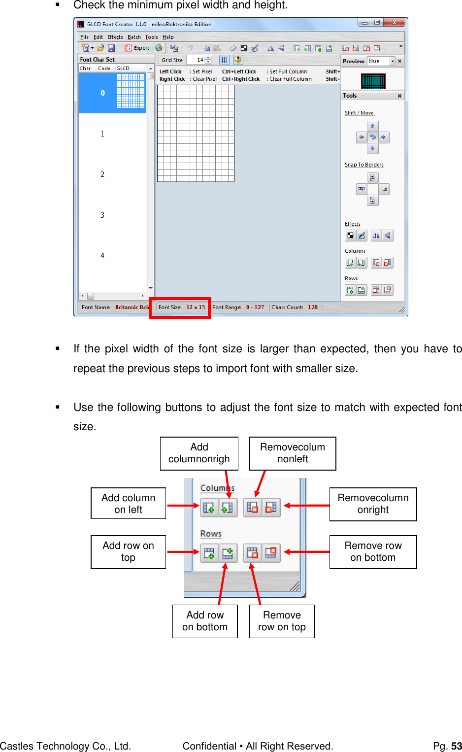
![Castles Technology Co., Ltd. Confidential • All Right Reserved. Pg. 51 5.2. Custom Font User may create font they preferred for displaying or printing on terminal. There are two zone defined: Zone 0x00 ~ 0x7F – ASCII characters, you may replace with the font type preferred or your own language character set. Zone 0x80 ~ 0xFF – Free to use, you may use for symbols. Following steps demonstrate how to create a 12x24 font. Run GLCD Font Creator Select [File] [New Font] [Import An Existing System Font]](https://usermanual.wiki/CASTLES-TECHNOLOGY/VEGA3000-UL/User-Guide-3133917-Page-51.png)
![Castles Technology Co., Ltd. Confidential • All Right Reserved. Pg. 54 After adjust font size, select [File] [Export for MicroElektronika]. Select output format as [mikroC].](https://usermanual.wiki/CASTLES-TECHNOLOGY/VEGA3000-UL/User-Guide-3133917-Page-54.png)
![Castles Technology Co., Ltd. Confidential • All Right Reserved. Pg. 55 Remove comment “// Code for char “ from offset 0x00 to 0x1F. Remove empty line if found. Then click [Save] button to save to file. Run Font Manager Tool. Click [Setting] button Remove Remove Remove Remove](https://usermanual.wiki/CASTLES-TECHNOLOGY/VEGA3000-UL/User-Guide-3133917-Page-55.png)
![Castles Technology Co., Ltd. Confidential • All Right Reserved. Pg. 56 Enter the file name, font id, and select the size. Click [Create] button, and select the C file previously created using GLCD Font Generator.](https://usermanual.wiki/CASTLES-TECHNOLOGY/VEGA3000-UL/User-Guide-3133917-Page-56.png)
![Castles Technology Co., Ltd. Confidential • All Right Reserved. Pg. 57 Select [Font Manager] tab and tick the newly createdfont, and press [Generate] button to export to FNT file.](https://usermanual.wiki/CASTLES-TECHNOLOGY/VEGA3000-UL/User-Guide-3133917-Page-57.png)
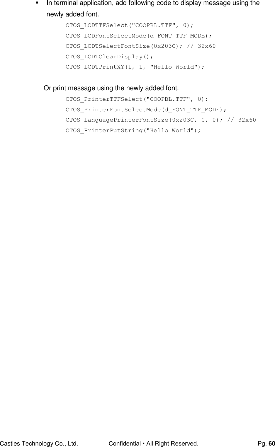
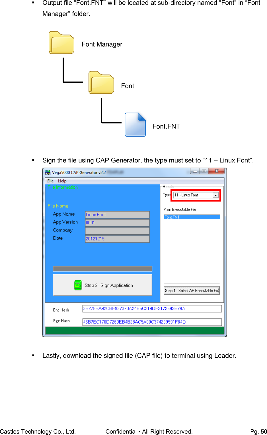
![Castles Technology Co., Ltd. Confidential • All Right Reserved. Pg. 58 Use CAP Generator to conver the FNT file to CAP. Set type to [11 – Linux Font], press [Step 1] button select the FNT file. Then press [Step 2] to generate CAP file. Download the font CAP file to terminal. In terminal application, add following code to display message using the newly created font. CTOS_LanguageConfig(0xA000,d_FONT_12x24,0,d_FALSE); CTOS_LanguageLCDSelectASCII(0xA000); CTOS_LCDTPrintXY(1, 1, "ABCDEFGH"); Or print message using the newly created font. CTOS_LanguagePrinterSelectASCII(0xA000); CTOS_PrinterPutString("ABCDEFGH");](https://usermanual.wiki/CASTLES-TECHNOLOGY/VEGA3000-UL/User-Guide-3133917-Page-58.png)
![Castles Technology Co., Ltd. Confidential • All Right Reserved. Pg. 59 5.3. Using TrueType Font (TTF) TrueType Font (TTF) is supported in VEGA3000 UltraLite.You may download the TrueType font preferred to terminal for displaying or printing. Following steps demonstrate how to use “Cooper Black” TrueType font. Copy the TTF file needed to a empty folder. Use CAP Generator to conver the TTF file to CAP. Set type to [11 – Linux Font], press [Step 1] button select the TTF file. Then press [Step 2] to generate CAP file. Download the font CAP file to terminal. TTF COOPBL.TTF](https://usermanual.wiki/CASTLES-TECHNOLOGY/VEGA3000-UL/User-Guide-3133917-Page-59.png)