CASTLES TECHNOLOGY VEGA5000SX3G EFTPOS User Manual VEGA5000 Book 2
CASTLES TECHNOLOGY CO., LTD. EFTPOS VEGA5000 Book 2
UserManual.wiki
>
CASTLES TECHNOLOGY
>
VEGA5000SX3G User Manual
User Manual
Navigation menu
Upload a User Manual
Namespaces
Wiki Guide
HTML
PDF
Info
Views
User Manual
Discussion / Help
Navigation
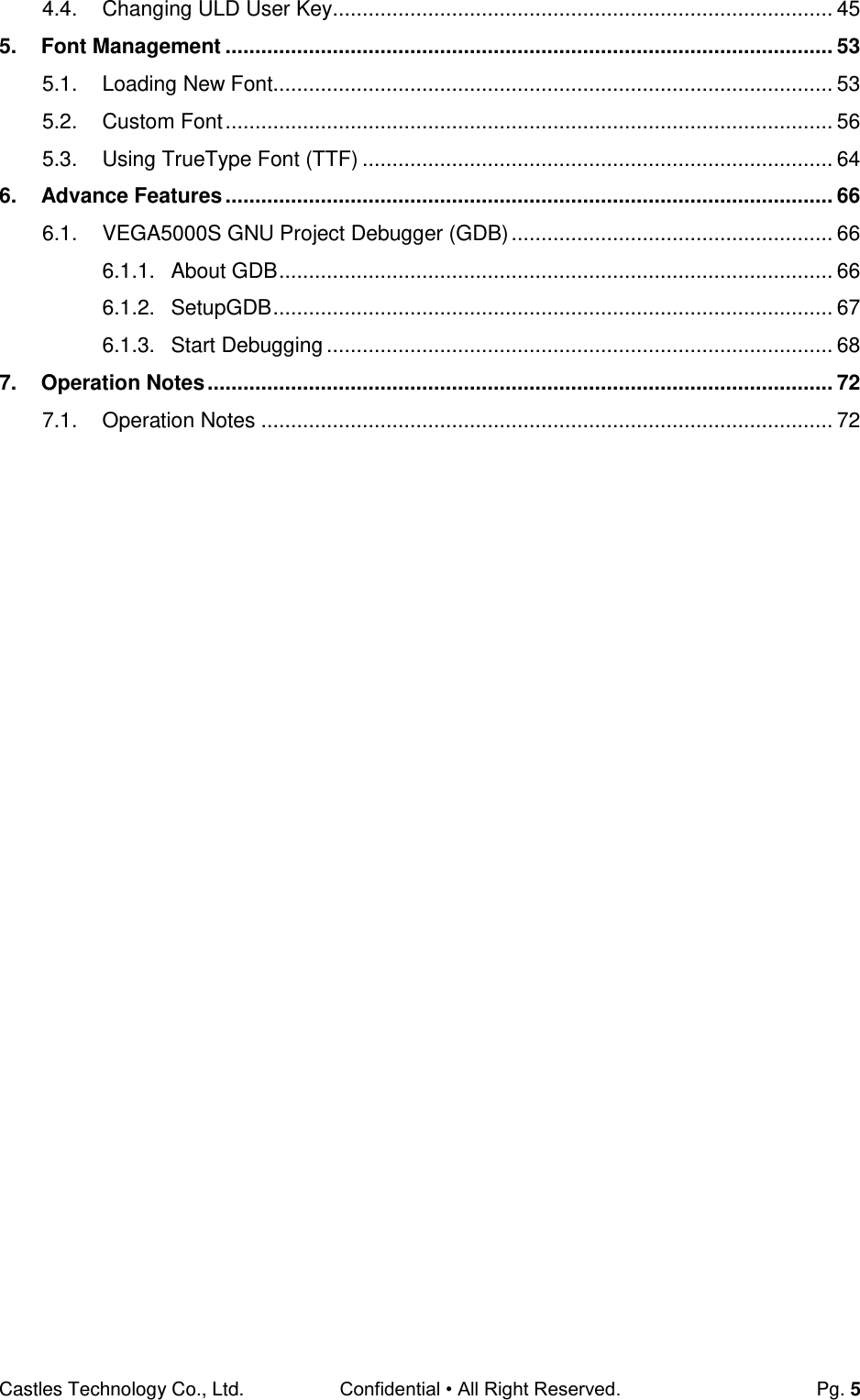
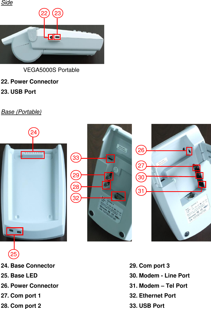
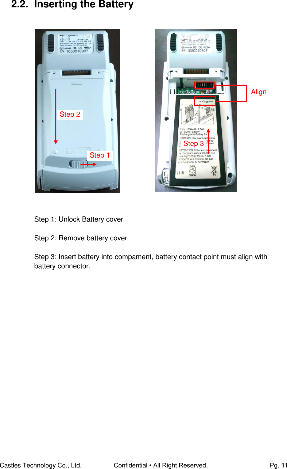
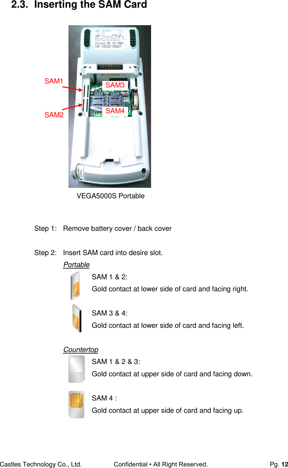
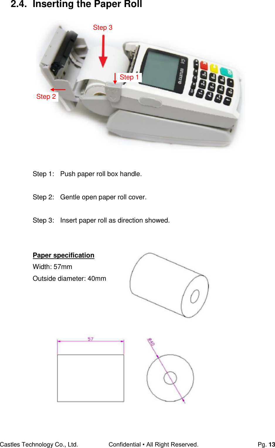
![Castles Technology Co., Ltd. Confidential • All Right Reserved. Pg. 8 2. Hardware Setup (Portable) 2.1. Parts of the Terminal Front (Portable and Countertop) 1. LCD Display ColorTFT : VEGA5000S 2. ProgrambleFunction Keys F1 : Power keyfor PT only.(Press 3s) 3. Navigation Key [] 4. Keyboard 5. Cancel Key 6. Clear Key 7. Enter Key 8. Magnectic Stripe Reader 9. Smart Card Reader 10. LED Left : Green Middle : Orange Right: Red 11. Contactless Module LED 12. Contactless Card Landing Zone 13. Paper Roll Handle VEGA5000S 1 2 3 5 8 9 10 6 7 4 13 12 11](https://usermanual.wiki/CASTLES-TECHNOLOGY/VEGA5000SX3G/User-Guide-2700345-Page-8.png)
![Castles Technology Co., Ltd. Confidential • All Right Reserved. Pg. 16 3. Basic Operation 3.1. Program Manager Upon power on, terminal will enter Program Manager if not default application selected. All user applications are list in Program Manager. User may select an application and run the application or view the application info, delete the application or set to default run upon power on. User may enter System Menu to configure terminal settings. Program Manager Press [F1] button to enter System Menu. Press [F2] button to toggle default application selection. Press [F3] button to delete application. Press [F4] button to view application info. Press [OK] button to run application. Press [] or [] button to select application. System Menu Page 1 Page 2 Press [] button to page 2. Program Manager -----------01/02 1.App1 2.App2 F1:Download System Menu 1.Download AP 2.System Info 3.Memory Status 4.Sys Settings 5.Test Utility 6.Factory Reset 7.Power Off System Menu 1.FK PWD Change 2.Share objMng 3.Castles TMS 4.ULD KEY HASH](https://usermanual.wiki/CASTLES-TECHNOLOGY/VEGA5000SX3G/User-Guide-2700345-Page-16.png)
![Castles Technology Co., Ltd. Confidential • All Right Reserved. Pg. 17 3.2. Download AP Download user application or kernel modules firmware. System Menu Press [1] button to enter Download AP menu. Download AP Menu Select download source: Press [1] button to select source as RS232 or USB connection and enter ULD download mode. Press [2] button to select source as USB disk. Press [3] button to select source as SD card. System Menu 1.Download AP 2.System Info 3.Memory Status 4.Sys Settings 5.Test Utility 6.Factory Reset 7.Power Off Download EX 1.RS232 or USB 2.USB Disk 3.SD Card Select DW Source](https://usermanual.wiki/CASTLES-TECHNOLOGY/VEGA5000SX3G/User-Guide-2700345-Page-17.png)
![Castles Technology Co., Ltd. Confidential • All Right Reserved. Pg. 18 3.3. System Info View kernel module firmware information. System Menu Press [2] button to enter System Info menu. System Info Menu Page 1 Page 2 Page 3 Press [OK] button to next page. Page 4 Page 5 Page 6 Page 7 Page 8 System Menu 1.Download AP 2.System Info 3.Memory Status 4.Sys Settings 5.Test Utility 6.Factory Reset 7.Power Off SYSTEM INFO ---Kernel Ver--- BOOTSULD : V0064 CRYPTOHAL: VF057 KMS : V0056 LINUXKNL : V0024 ROOTFS : V0050 SYSTEM INFO --- KOVer --- SECURITY : V0076 SYSUPD : V0080 KMODEM : N/A DRV : V0089 USB : V0078 SC : V0083 SYSTEM INFO --- SO Ver 1 --- UART : V0072 USBH : V0070 MODEM : V0075 ETHERNET : V0078 FONT : V0076 LCD : V0073 SYSTEM INFO --- SO Ver 2 --- PRT : V0073 RTC : V0073 ULDPM : V0078 PPP MODEM: V0086 EMVL2 : V0072 KMS : V0073 SYSTEM INFO --- SO Ver 3 --- FS : V0075 GSM : V0080 BARCODE : V0073 TMS : V0072 TLS : V0071 CLVW : V0076 SYSTEM INFO --- SO Ver 4 --- CTOSAPI : V0083 SYSTEM INFO --- HWMVer --- CRDL/ETHE: V3004 CLM-MP : V0015 --- APVer --- ULDPM : V0043 SYSTEM INFO --- HWMVer --- HUSBID:0CA6A050 CUSBID:N/A --Factory S/N--- 0000010600035717](https://usermanual.wiki/CASTLES-TECHNOLOGY/VEGA5000SX3G/User-Guide-2700345-Page-18.png)
![Castles Technology Co., Ltd. Confidential • All Right Reserved. Pg. 19 3.4. Memory Status View terminal flash memory and RAM information. System Menu Press [3] button to enter Memory Status menu. Memory Status Menu System Menu 1.Download AP 2.System Info 3.Memory Status 4.Sys Settings 5.Test Utility 6.Factory Reset 7.Power Off MEMORY STATUS --FLASH Memory-- Total: 31616KB Used : 22640KB --SDRAM Memory-- Total: 31872KB Used : 10908KB](https://usermanual.wiki/CASTLES-TECHNOLOGY/VEGA5000SX3G/User-Guide-2700345-Page-19.png)
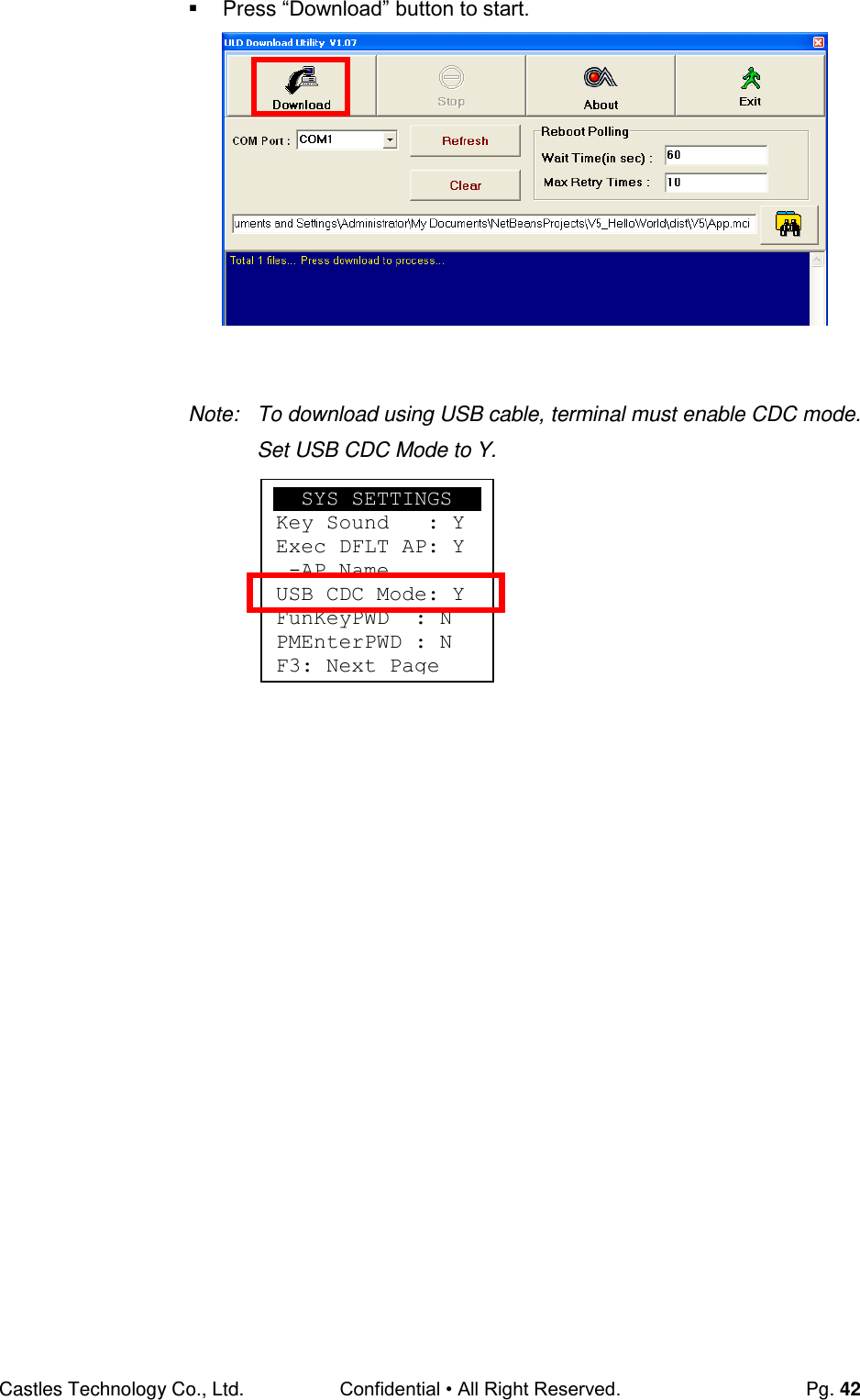
![Castles Technology Co., Ltd. Confidential • All Right Reserved. Pg. 20 3.5. System Settings View or change terminal system settings. Setting Descriptions Key Sound Enable (Y) or disable (N) the beep sound when pressing any key. Exec DFLT AP Enable (Y) or disable (N) execution of default selected application. USB CDC Mode Enable (Y) or disable (N) USB CDC mode. FunKey PWD Enable (Y) or disable (N) password protection to access function key (F1 ~ F4) in Program Manager. PMEnter PWD Enable (Y) or disable (N) password protection to enter Program Manager. SET USB Host Enable (Y) or disable (N) USB host mode. Base USB CDC Enable (Y) or disable (N) USB CDC mode in base unit. [Portable model only] List SHR Lib Enable (Y) or disable (N) to list all shared libraries in Program Manager. Key MNG Mode <TBC> Bat Threshld Battery charging threshold value. [Portable model only] Null Cradle Enable (Y) if base is null cradle. [Portable model only] Debug Mode Enable (Y) or disable (N) console debug mode. Debug Port Serial port for console debug. Mobil AutoON <TBC> GDB Mode Enable (Y) or disable (N) GDB mode. [VEGA5000S only] GDB Timeout GDB connection timeout. [VEGA5000S only] GDB Channel GDB connection channel. [VEGA5000S only] ETHER IP/PORT GDB Ethernet connection setting. [VEGA5000S only]](https://usermanual.wiki/CASTLES-TECHNOLOGY/VEGA5000SX3G/User-Guide-2700345-Page-20.png)
![Castles Technology Co., Ltd. Confidential • All Right Reserved. Pg. 21 System Menu Press [4] button to enter System Settings menu. System Settings Menu Page 1 Press [] or [] button to select setting. Press [OK] button to change the setting value. Press [] button to toggle Y N Y. Press [F3] button to next page. Page 2 Press [] or [] button to select setting. Press [OK] button to change the setting value. Press [] button to toggle Y N Y. Press [F2] button to previous page. Press [F3] button to next page. System Menu 1.Download AP 2.System Info 3.Memory Status 4.Sys Settings 5.Test Utility 6.Factory Reset 7.Power Off SYS SETTINGS Key Sound : Y Exec DFLT AP: Y -AP Name USB CDC Mode: Y FunKeyPWD : N PMEnterPWD : N F3: Next Page SYS SETTINGS SET USB Host: N Base USB CDC: X List SHR Lib: N Key MNG Mode: 0 Bat Threshld: X Null Cradle : X F2:Prev F3:Next](https://usermanual.wiki/CASTLES-TECHNOLOGY/VEGA5000SX3G/User-Guide-2700345-Page-21.png)
![Castles Technology Co., Ltd. Confidential • All Right Reserved. Pg. 22 Page 3 Press [] button to select setting. Press [OK] button to change the setting value. Press [] button to toggle Y N Y. Press [F2] button to previous page. Press [F3] button to next page. Page 4 (VEGA5000S only) Press [] button to select setting. Press [OK] button to change the setting value. Press [] button to toggle Y N Y. Press [F2] button to previous page. SYS SETTINGS Debug Mode : N Debug Port : X Mobil AutoON: Y F2:Prev F3:Next SYS SETTINGS GDB Mode : Y GDB Timeout: 60s GDB Channel : E ETHER IP/PORT 192.120.100.222 5000 F2:Prev Page](https://usermanual.wiki/CASTLES-TECHNOLOGY/VEGA5000SX3G/User-Guide-2700345-Page-22.png)
![Castles Technology Co., Ltd. Confidential • All Right Reserved. Pg. 23 3.6. Test Utility Perform terminal hardware components diagnostic. System Menu Press [5] button to enter Test Utility menu. Test Utility Menu Page 1 Press [1] button to diagnose LCD. Press [2] button to diagnose keyboard. Press [3] button to diagnose flash memory. Press [4] button to diagnose smart card module. Press [5] button to diagnose backlight. Press [6] button to diagnose magnetic stripe reader. Press [7] button to diagnose LED. Press [8] button to diagnose real time clock. Press [9] button to diagnose printer. Press [0] button to view font. Press [F2] button to enter Communication Test Menu. Press [F3] button to power off. Press [] button to next page. Note: Default password for changing RTC is 8418. System Menu 1.Download AP 2.System Info 3.Memory Status 4.Sys Settings 5.Test Utility 6.Factory Reset 7.Power Off Main Menu 0009 1:LCD 2:KBD 3:FLASH 4:SCM 5:Light 6:MSR 7:LED 8:RTC 9:PRNTR 0:FONT [F2]Comm Menu [F3]Power Off](https://usermanual.wiki/CASTLES-TECHNOLOGY/VEGA5000SX3G/User-Guide-2700345-Page-23.png)
![Castles Technology Co., Ltd. Confidential • All Right Reserved. Pg. 24 Page 2 Press [1] button to diagnose contactless reader in transparent mode. Press [2] button to diagnose contactless card. Press [3] button to diagnose SD memory card. Press [] button to previous page. Press [X] button to exit. Communication Test Menu Press [1] button to diagnose Com 1. Press [2] button to diagnose Com 2. Press [3] button to diagnose Com 3. Press [4] button to diagnose Ethernet module. Press [5] button to diagnose USB. Press [6] button to diagnose modem. Press [7] button to diagnose GPRS. Press [8] button to diagnose all, item 1 to 7. Main Menu 1:CL_Transparent 2:CL Card Test 3:SD Card Test :PAGE1 X:EXIT Communicate Test 1. COM1 2. Com2 3. Com3 4. Ethernet Test 5. USB Test 6. Modem Test 7. GPRS Test 8. All Test](https://usermanual.wiki/CASTLES-TECHNOLOGY/VEGA5000SX3G/User-Guide-2700345-Page-24.png)
![Castles Technology Co., Ltd. Confidential • All Right Reserved. Pg. 25 3.7. Factory Reset Perform factory reset, all user application, fonts and data will be deleted. System Menu Press [6] button to enter Factory Reset menu. Factory Reset Menu Press [OK] button to perform factory reset. Enter factory reset password.Default password: 8418 System Menu 1.Download AP 2.System Info 3.Memory Status 4.Sys Settings 5.Test Utility 6.Factory Reset 7.Power Off Factory Reset OK to reset ? Factory Reset Password : ****](https://usermanual.wiki/CASTLES-TECHNOLOGY/VEGA5000SX3G/User-Guide-2700345-Page-25.png)
![Castles Technology Co., Ltd. Confidential • All Right Reserved. Pg. 26 3.8. Power Off Power off terminal. System Menu Press [7] button to power off terminal. System Menu 1.Download AP 2.System Info 3.Memory Status 4.Sys Settings 5.Test Utility 6.Factory Reset 7.Power Off](https://usermanual.wiki/CASTLES-TECHNOLOGY/VEGA5000SX3G/User-Guide-2700345-Page-26.png)
![Castles Technology Co., Ltd. Confidential • All Right Reserved. Pg. 27 3.9. Function Key Password Change Change function key access password. System Menu (Page 2) Press [1] button to enter FunKey Password menu. FunKey Password Menu Enter current password. (Default password is "0000") Enter new password. Enter new password again to confirm. System Menu 1.FK PWD Change 2.Share objMng 3.Castles TMS 4.ULD KEY HASH FunKey Password Enter Password: **** FunKey Password New Password: **** Confirm Password **** FunKey Password New Password: **** Confirm Password **** PWD Changed OK](https://usermanual.wiki/CASTLES-TECHNOLOGY/VEGA5000SX3G/User-Guide-2700345-Page-27.png)
![Castles Technology Co., Ltd. Confidential • All Right Reserved. Pg. 28 3.10. Share Object Management View share object in terminal. System Menu (Page 2) Press [2] button to enter Share Object Management menu. Share Object Management Menu Press [1] button to view shared library. Press [2] button to view shared file. System Menu 1.FK PWD Change 2.Share objMng 3.Castles TMS 4.ULD KEY HASH Share objMng 1.Share LIB 2.Share File](https://usermanual.wiki/CASTLES-TECHNOLOGY/VEGA5000SX3G/User-Guide-2700345-Page-28.png)
![Castles Technology Co., Ltd. Confidential • All Right Reserved. Pg. 29 3.11. CTOS TMS Connect to TMS (Terminal Management Softare) server, set or delete TMS configuration. System Menu (Page 2) Press [3] button to enter Castles TMS menu. Castles TMS Menu Press [1] button to connect to TMS server. Press [2] button to set TMS configuration. Press [3] button to delete TMS configuration. System Menu 1.FK PWD Change 2.Share objMng 3.Castles TMS 4.ULD KEY HASH CASTLES TMS 1.Connect Server 2.SetConfig 3.DelConfig](https://usermanual.wiki/CASTLES-TECHNOLOGY/VEGA5000SX3G/User-Guide-2700345-Page-29.png)
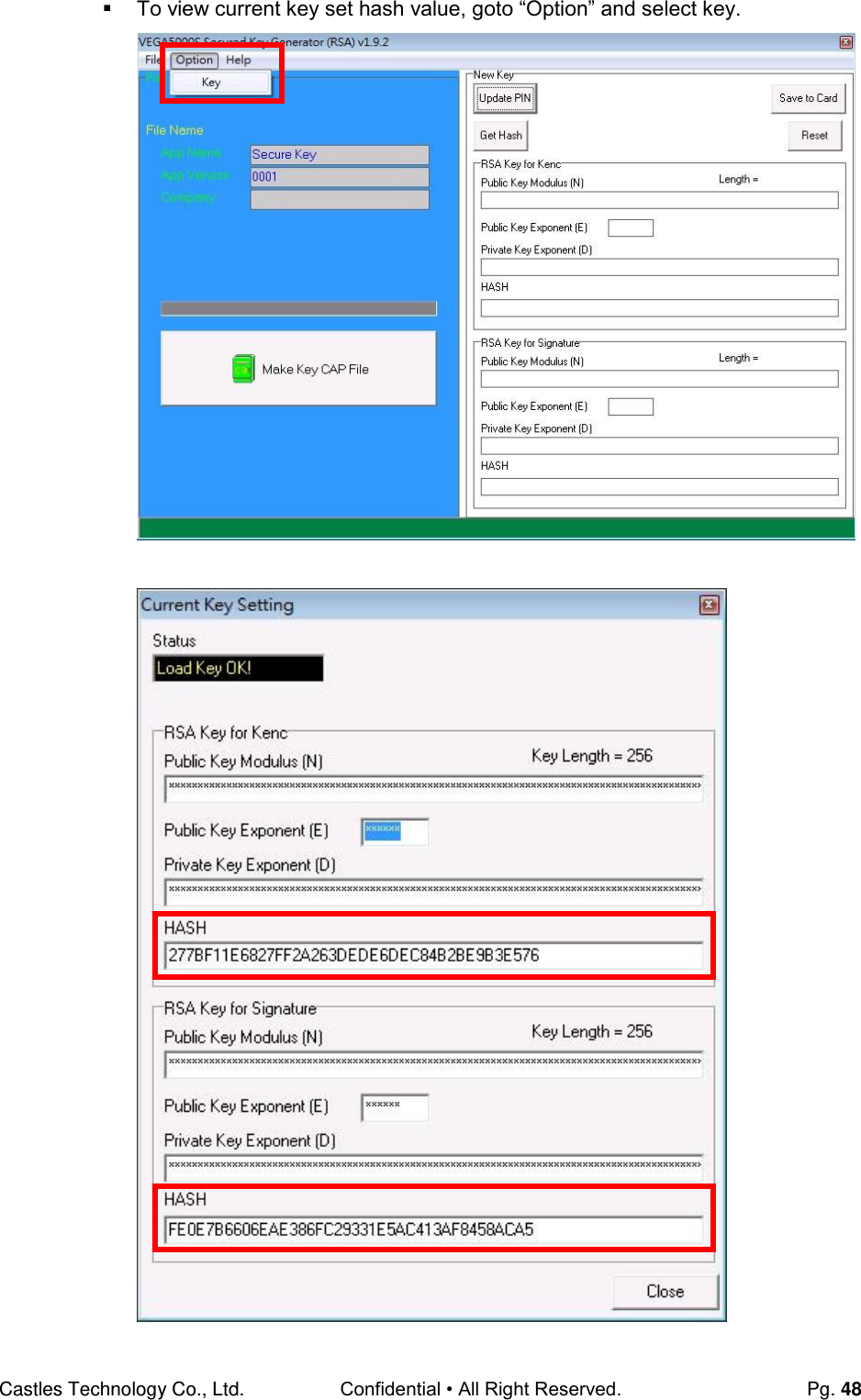
![Castles Technology Co., Ltd. Confidential • All Right Reserved. Pg. 30 3.12. ULD Key Hash View ULD user keyset hash value. System Menu (Page 2) Press [4] button to view hash value. System Menu 1.FK PWD Change 2.Share objMng 3.Castles TMS 4.ULD KEY HASH USER ENC KEY 9572BC621C1D5406 0856D00BCC207000 D3320077 USER SIGN KEY A927768EA7DD7B9E 7E3F395C10726B6F 43B35C5A](https://usermanual.wiki/CASTLES-TECHNOLOGY/VEGA5000SX3G/User-Guide-2700345-Page-30.png)
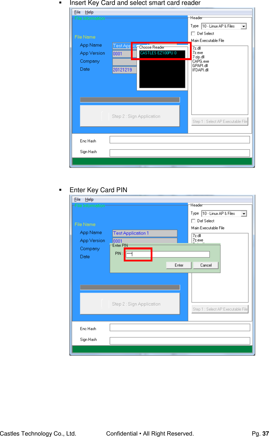
![Castles Technology Co., Ltd. Confidential • All Right Reserved. Pg. 41 Select COM port Browse and select mci file or mmci file Setup terminal to enter download mode Press [F1] button in Program Manager (PM) Press [1] button to select “1. Download AP“ Press [1] button again to select download via RS232 or USB](https://usermanual.wiki/CASTLES-TECHNOLOGY/VEGA5000SX3G/User-Guide-2700345-Page-41.png)
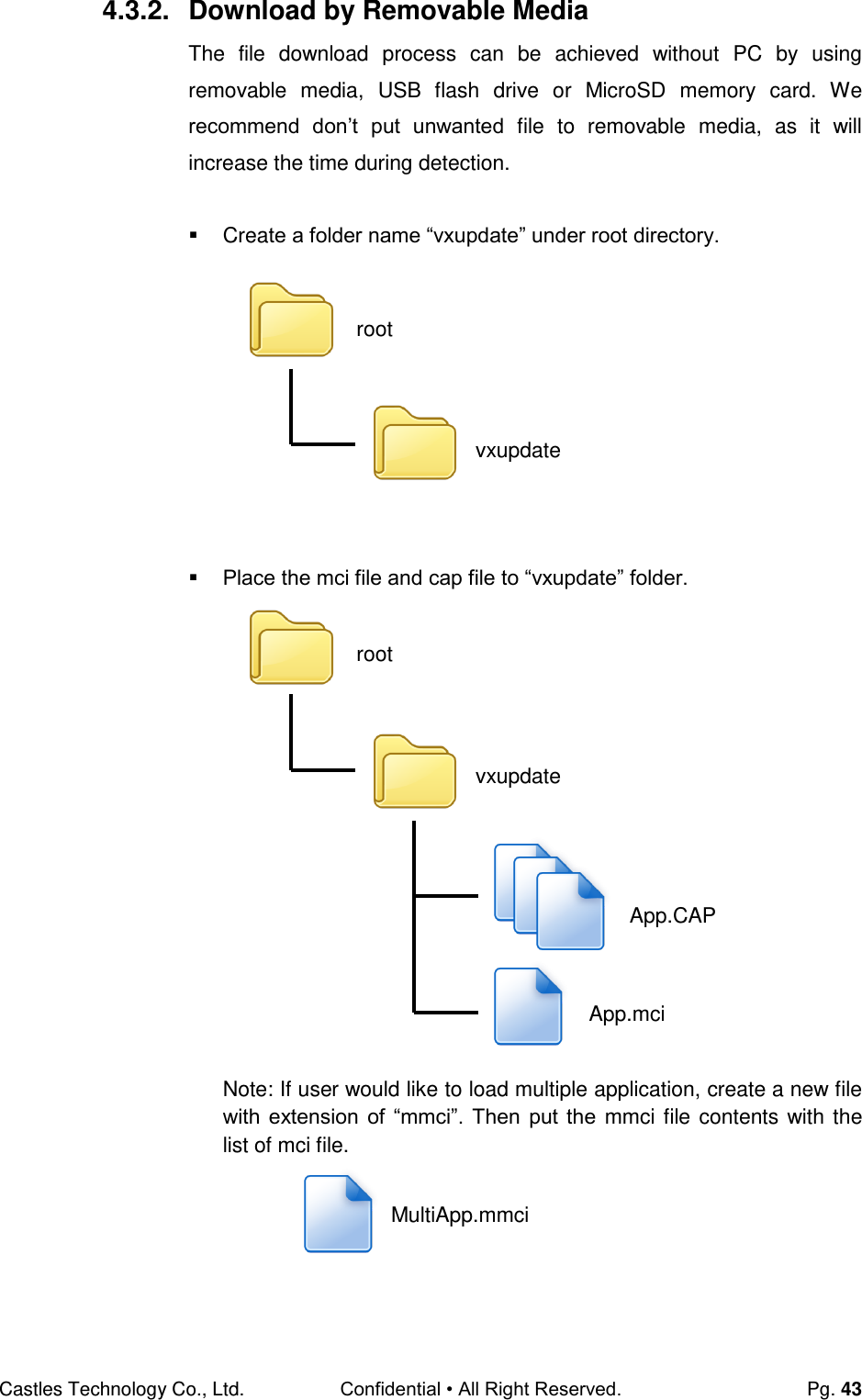
![Castles Technology Co., Ltd. Confidential • All Right Reserved. Pg. 44 Insert removable media to terminal, and select the removable media type in “Download AP” menu. Download AP Menu o Press [2] button to select USB flash drive. o Press [3] button to select MicroSD card. Finally, terminal will process the file “vxupdate” folder. Download EX 1.RS232 or USB 2.USB Disk 3.SD Card Select DW Source](https://usermanual.wiki/CASTLES-TECHNOLOGY/VEGA5000SX3G/User-Guide-2700345-Page-44.png)
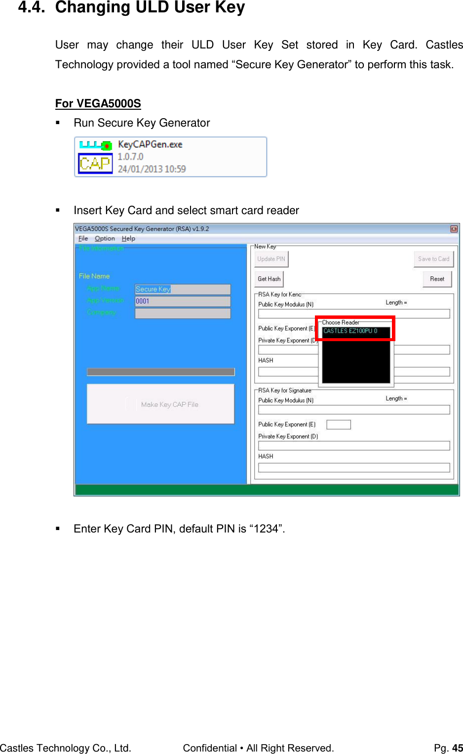
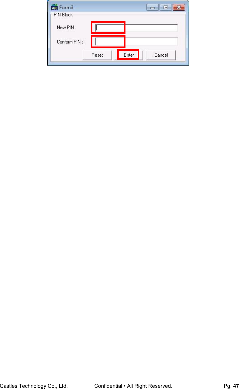
![Castles Technology Co., Ltd. Confidential • All Right Reserved. Pg. 46 To change Key Card PIN, press “Update PIN” button. If not, please skip this steps. o Enter new PIN, enter new PIN again to confirm, then press [Enter] button to change PIN in Key Card.](https://usermanual.wiki/CASTLES-TECHNOLOGY/VEGA5000SX3G/User-Guide-2700345-Page-46.png)
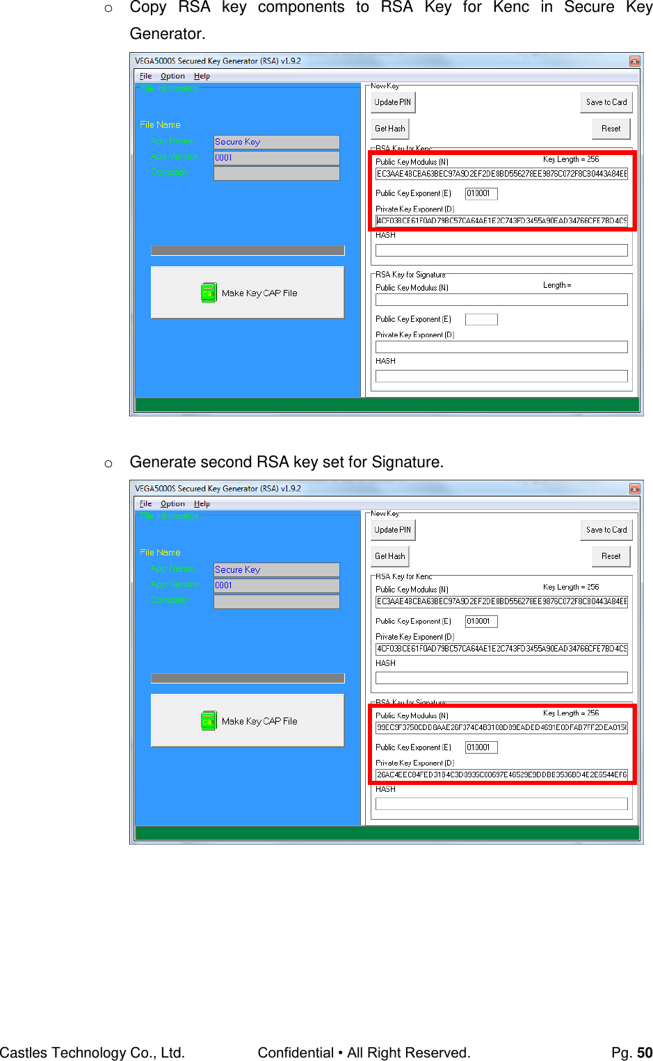
![Castles Technology Co., Ltd. Confidential • All Right Reserved. Pg. 49 To generate new user key set o Run RSA Key Generator o Select Key Length as 2048 (bits), then press [Generate] button to generate the RSA key set. Result:](https://usermanual.wiki/CASTLES-TECHNOLOGY/VEGA5000SX3G/User-Guide-2700345-Page-49.png)
![Castles Technology Co., Ltd. Confidential • All Right Reserved. Pg. 51 o Click [Get Hash] button to calculate the hash value for key sets. o Please copy down all the values into a text file and keep in a safe place. You will need this if you need to create duplicate Key Card. To generate the key CAP for the newly generated user key set, press [Make Key CAP File] button.](https://usermanual.wiki/CASTLES-TECHNOLOGY/VEGA5000SX3G/User-Guide-2700345-Page-51.png)
![Castles Technology Co., Ltd. Confidential • All Right Reserved. Pg. 52 The output file will be located in the Secure Key Generator folder. To update the newly generated key set to Key Card, press [Save to Card] button to write the key set to Key Card. SecureKeyGenerator key.mci key.cap](https://usermanual.wiki/CASTLES-TECHNOLOGY/VEGA5000SX3G/User-Guide-2700345-Page-52.png)
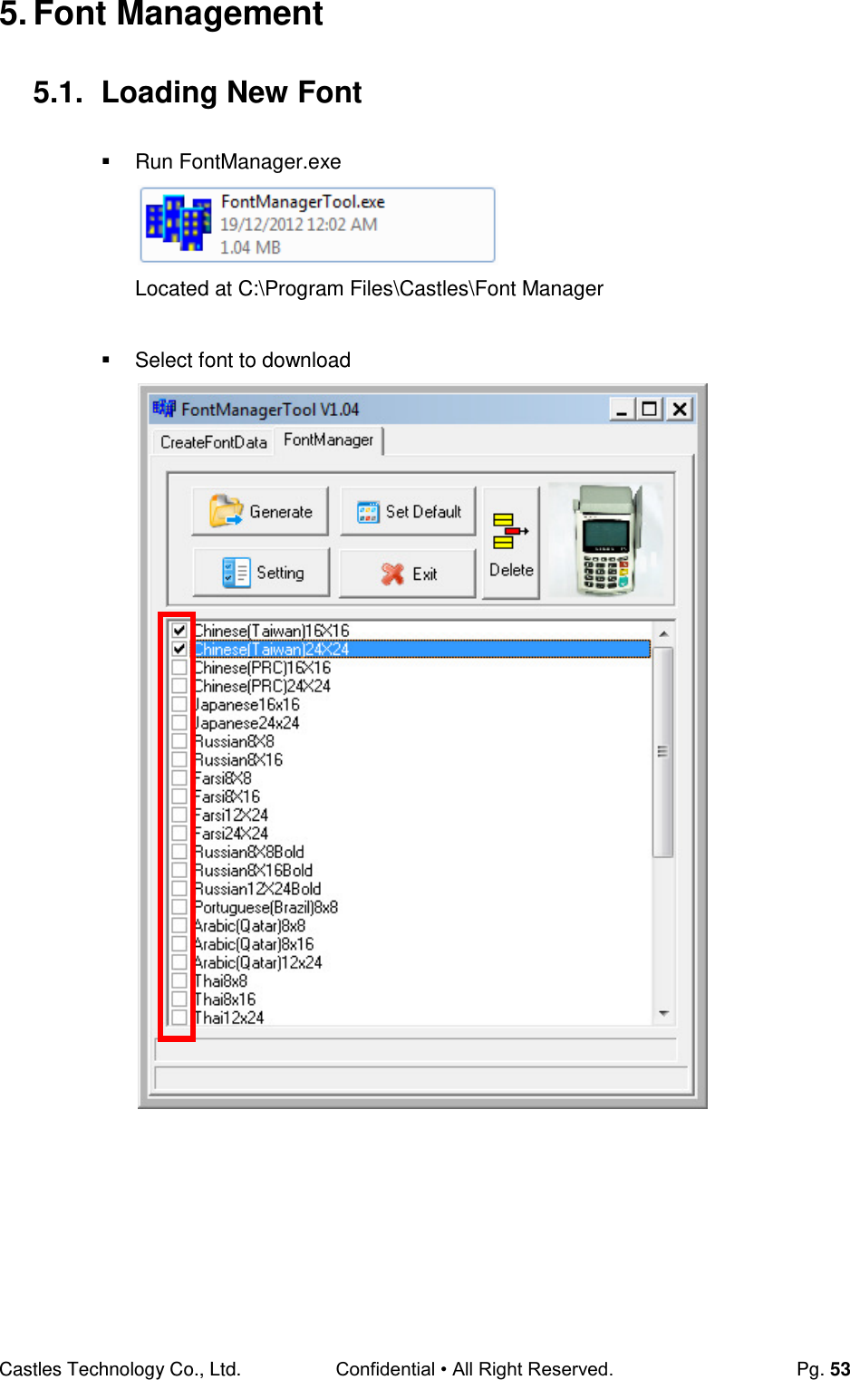
![Castles Technology Co., Ltd. Confidential • All Right Reserved. Pg. 54 Press [Setting] button to configure terminal type. Select VEGA5000, press [Save] button to save and return font manager. Press [Generate] to create the font file.](https://usermanual.wiki/CASTLES-TECHNOLOGY/VEGA5000SX3G/User-Guide-2700345-Page-54.png)
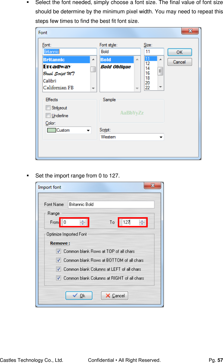
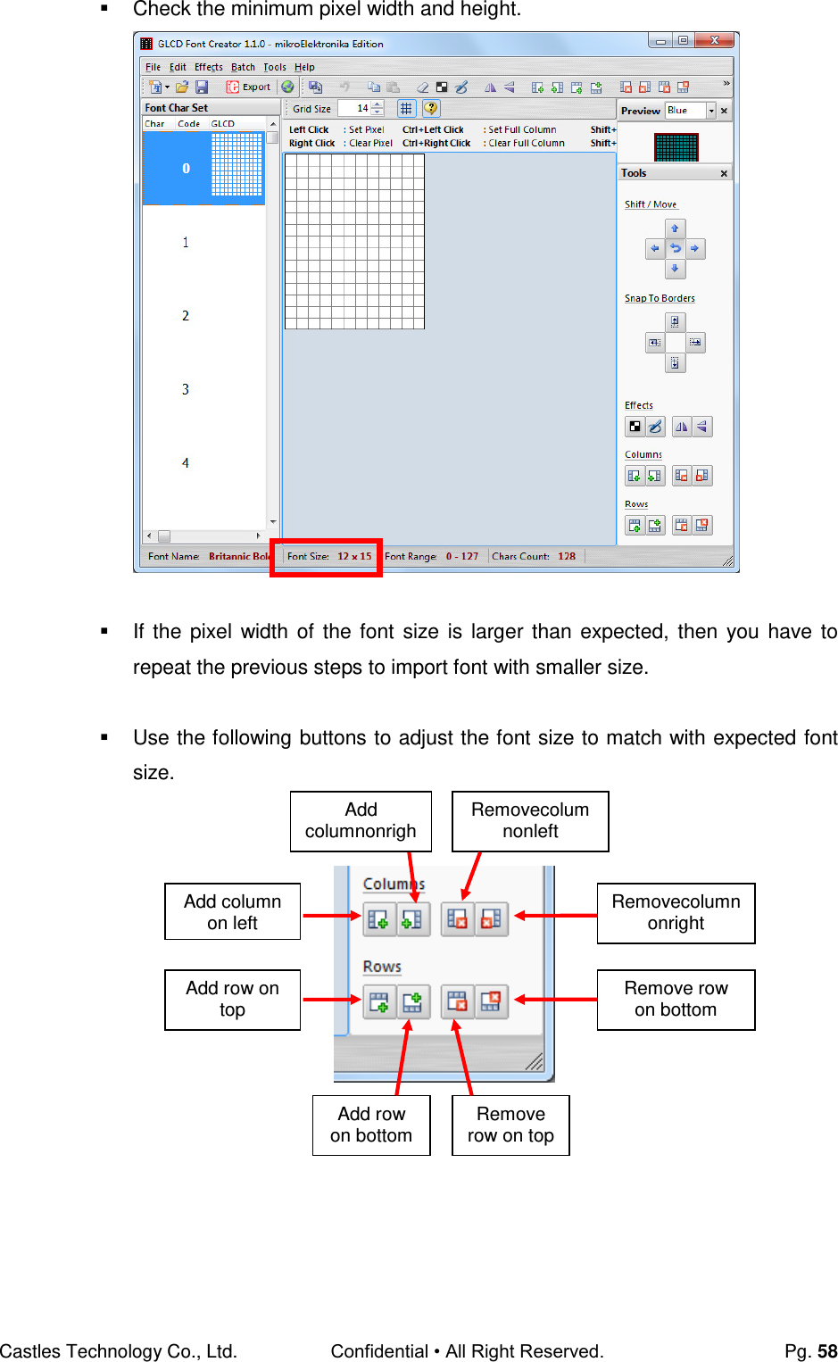
![Castles Technology Co., Ltd. Confidential • All Right Reserved. Pg. 56 5.2. Custom Font User may create font they preferred for displaying or printing on terminal. There are two zone defined: Zone 0x00 ~ 0x7F – ASCII characters, you may replace with the font type preferred or your own language character set. Zone 0x80 ~ 0xFF – Free to use, you may use for symbols. Following steps demonstrate how to create a 12x24 font. Run GLCD Font Creator Select [File] [New Font] [Import An Existing System Font]](https://usermanual.wiki/CASTLES-TECHNOLOGY/VEGA5000SX3G/User-Guide-2700345-Page-56.png)
![Castles Technology Co., Ltd. Confidential • All Right Reserved. Pg. 59 After adjust font size, select [File] [Export for MicroElektronika]. Select output format as [mikroC].](https://usermanual.wiki/CASTLES-TECHNOLOGY/VEGA5000SX3G/User-Guide-2700345-Page-59.png)
![Castles Technology Co., Ltd. Confidential • All Right Reserved. Pg. 60 Remove comment “// Code for char “ from offset 0x00 to 0x1F. Remove empty line if found. Then click [Save] button to save to file. Run Font Manager Tool. Click [Setting] button Remove Remove Remove Remove](https://usermanual.wiki/CASTLES-TECHNOLOGY/VEGA5000SX3G/User-Guide-2700345-Page-60.png)
![Castles Technology Co., Ltd. Confidential • All Right Reserved. Pg. 61 Enter the file name, font id, and select the size. Click [Create] button, and select the C file previously created using GLCD Font Generator.](https://usermanual.wiki/CASTLES-TECHNOLOGY/VEGA5000SX3G/User-Guide-2700345-Page-61.png)
![Castles Technology Co., Ltd. Confidential • All Right Reserved. Pg. 62 Select [Font Manager] tab and tick the newly creately font, and press [Generate] button to export to FNT file.](https://usermanual.wiki/CASTLES-TECHNOLOGY/VEGA5000SX3G/User-Guide-2700345-Page-62.png)
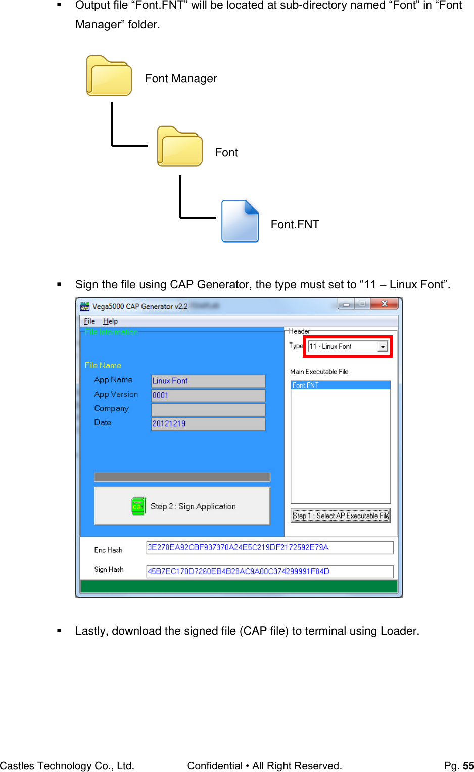
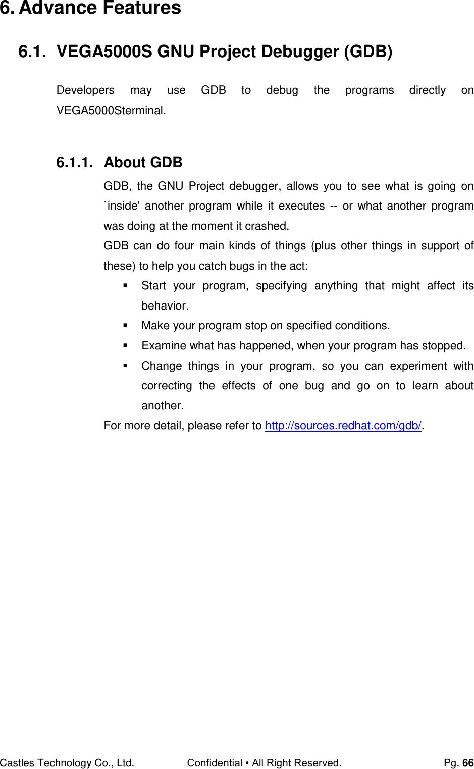
![Castles Technology Co., Ltd. Confidential • All Right Reserved. Pg. 63 Use CAP Generator to conver the FNT file to CAP. Set type to [11 – Linux Font], press [Step 1] button select the FNT file. Then press [Step 2] to generate CAP file. Download the font CAP file to terminal. In terminal application, add following code to display message using the newly created font. CTOS_LanguageConfig(0xA000,d_FONT_12x24,0,d_FALSE); CTOS_LanguageLCDSelectASCII(0xA000); CTOS_LCDTPrintXY(1, 1, "ABCDEFGH"); Or print message using the newly created font. CTOS_LanguagePrinterSelectASCII(0xA000); CTOS_PrinterPutString("ABCDEFGH");](https://usermanual.wiki/CASTLES-TECHNOLOGY/VEGA5000SX3G/User-Guide-2700345-Page-63.png)
![Castles Technology Co., Ltd. Confidential • All Right Reserved. Pg. 64 5.3. Using TrueType Font (TTF) TrueType Font (TTF) is only supported in VEGA5000S terminal.You may download the TrueType font preferred to terminal for displaying or printing. Following steps demonstrate how to use “Cooper Black” True Type font. Copy the TTF file needed to a empty folder. Use CAP Generator to conver the TTF file to CAP. Set type to [11 – Linux Font], press [Step 1] button select the TTF file. Then press [Step 2] to generate CAP file. Download the font CAP file to terminal. TTF COOPBL.TTF](https://usermanual.wiki/CASTLES-TECHNOLOGY/VEGA5000SX3G/User-Guide-2700345-Page-64.png)
![Castles Technology Co., Ltd. Confidential • All Right Reserved. Pg. 67 6.1.2. SetupGDB Access to GDB Setting Menu. Press [4] button to enter System Settings menu. Press [F3] button three times to GDB Setting Menu (page 4). Change following settings: Set GDB Mode to Y (enable) Set GDB Timeout, the time that GDB server (on terminal) waits for connection. Default is 60 seconds. Set GDB Channel, the communication channel between GDB server (on terminal) and SDK IDE on PC. ‘E’ indicates to use TCP/IP channel ‘U’ indicates USB mode Set Ethernet IP & Port, terminal IP address and GDB server (on terminal) port. Ifcoummincation channel is set to TCP/IP. Press [] button to select setting. Press [OK] button to change the setting value. Press [] button to toggle Y N Y. System Menu 1.Download AP 2.System Info 3.Memory Status 4.Sys Settings 5.Test Utility 6.Factory Reset 7.Power Off SYS SETTINGS GDB Mode : N GDB Timeout : X GDB Channel : X ETHER IP/PORT F2:Prev Page SYS SETTINGS GDB Mode : Y GDB Timeout: 60s GDB Channel : E ETHER IP/PORT 192.168.0.71 5000 F2:Prev Page Change to SYS SETTINGS GDB Mode : N GDB Timeout : X GDB Channel : X ETHER IP/PORT F2:Prev Page](https://usermanual.wiki/CASTLES-TECHNOLOGY/VEGA5000SX3G/User-Guide-2700345-Page-67.png)
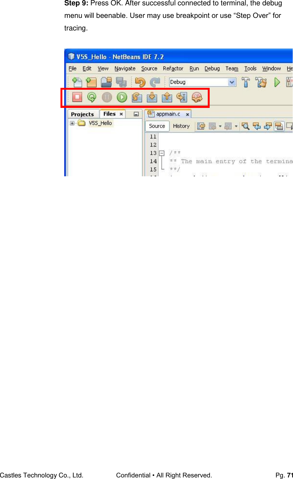
![Castles Technology Co., Ltd. Confidential • All Right Reserved. Pg. 69 Step 5: Sign the application and load the CAP files to terminal. Step 6: Execute the application. Step 7: Press [OK] button to confirm open debug mode. Terminal will wait for connection from SDK IDE until timeout. Step 7: In SDK IDE, from Debug menu select “Attach Debugger…”. Program Manager -----------01/02 1.V5S_Hello F1:Download Open Debug Mode Confirm? Y:OK N:X Press OK Local IP: 192.168.0.71 Listen Port: 5000 Listening… 59](https://usermanual.wiki/CASTLES-TECHNOLOGY/VEGA5000SX3G/User-Guide-2700345-Page-69.png)