CASTLES TECHNOLOGY VEGA5000SX3G EFTPOS User Manual VEGA5000 Book 2
CASTLES TECHNOLOGY CO., LTD. EFTPOS VEGA5000 Book 2
User Manual

Castles Technology Co., Ltd. Confidential • All Right Reserved. Pg. 2
WARNING
Information in this document is subject to change without prior notice.
No part of this publication may be reproduced, transmitted, stored in a retrieval
system, nor translated into any human or computer language, in any form or by any
means, electronic, mechanical, magnetic, optical, chemical, manual, or otherwise,
without the prior written permission of Castles Technology Co., Ltd.
All trademarks mentioned are proprietary of their respective owners.

Castles Technology Co., Ltd. Confidential • All Right Reserved. Pg. 3
Revision History
Version
Date
Descriptions
1.0
Nov 18, 2012
Initial creation.
1.01
May 12, 2014
Add the terminal starting up description
1.1
May 12, 2014
Add the description of GDB via USB
Castles Technology Co., Ltd. Confidential • All Right Reserved. Pg. 4
Contents
1. Introduction .................................................................................................................. 6
1.1. Type of Terminal .................................................................................................. 6
2. Hardware Setup (Portable) .......................................................................................... 8
2.1. Parts of the Terminal ........................................................................................... 8
2.2. Inserting the Battery ........................................................................................... 11
2.3. Inserting the SAM Card ..................................................................................... 12
2.4. Inserting the Paper Roll ..................................................................................... 13
2.5. Inserting the GSM SIM Card .............................................................................. 14
2.6. Inserting the Memory card ................................................................................. 15
3. Basic Operation ......................................................................................................... 16
3.1. Program Manager .............................................................................................. 16
3.2. Download AP ..................................................................................................... 17
3.3. System Info........................................................................................................ 18
3.4. Memory Status .................................................................................................. 19
3.5. System Settings ................................................................................................. 20
3.6. Test Utility .......................................................................................................... 23
3.7. Factory Reset .................................................................................................... 25
3.8. Power Off .......................................................................................................... 26
3.9. Function Key Password Change ........................................................................ 27
3.10. Share Object Management ................................................................................ 28
3.11. CTOS TMS ........................................................................................................ 29
3.12. ULD Key Hash ................................................................................................... 30
4. Secure File Loading ................................................................................................... 31
4.1. ULD Key System ............................................................................................... 31
4.1.1. ULD Manufacturer Key ........................................................................... 31
4.1.2. ULD User Key ........................................................................................ 33
4.1.3. Key Change ........................................................................................... 33
4.2. File Signing ........................................................................................................ 34
4.2.1. Signing Kernel Module ........................................................................... 34
4.2.2. Signing User Files .................................................................................. 36
4.3. File Loading ....................................................................................................... 40
4.3.1. Download by User Loader ...................................................................... 40
4.3.2. Download by Removable Media ............................................................. 43
Castles Technology Co., Ltd. Confidential • All Right Reserved. Pg. 5
4.4. Changing ULD User Key.................................................................................... 45
5. Font Management ...................................................................................................... 53
5.1. Loading New Font.............................................................................................. 53
5.2. Custom Font ...................................................................................................... 56
5.3. Using TrueType Font (TTF) ............................................................................... 64
6. Advance Features ...................................................................................................... 66
6.1. VEGA5000S GNU Project Debugger (GDB) ...................................................... 66
6.1.1. About GDB ............................................................................................. 66
6.1.2. SetupGDB .............................................................................................. 67
6.1.3. Start Debugging ..................................................................................... 68
7. Operation Notes ......................................................................................................... 72
7.1. Operation Notes ................................................................................................ 72
Castles Technology Co., Ltd. Confidential • All Right Reserved. Pg. 6
1. Introduction
This document provide a guildeline on operating and configuringCastles VEGA5000S
terminal.
The scope of this document includesetting up the terminal, basic operation, application
life cycle, and some advance features.
1.1. Type of Terminal
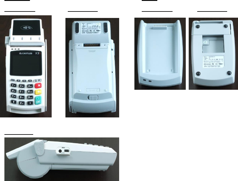
There are two types of VEGA5000S terminal, portable and countertop. The major
different is portable type can be battery operated.
Portable type is designed as two pieces of hardware, handset and base unit.
Handset unit features major components, and also optional contactless reader
and GRPS modem.Wired connection like power, modem, Ethernet, USB or serial
ports, are be located in base unit. There are additional power connection and
USB port on handset unit, allow the handset unit can be operated alone.
Handset Base
Front View Rear View Front View Rear View
Side View
Castles Technology Co., Ltd. Confidential • All Right Reserved. Pg. 7
To start up the terminal,portable type needs to press “F1” key butcountertop
typewill auto start when the power connector is connected with adapter.
Castles Technology Co., Ltd. Confidential • All Right Reserved. Pg. 8
2. Hardware Setup (Portable)
2.1. Parts of the Terminal
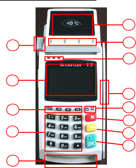
Front (Portable and Countertop)
1. LCD Display
ColorTFT : VEGA5000S
2. ProgrambleFunction Keys
F1 : Power keyfor PT
only.(Press 3s)
3. Navigation Key []
4. Keyboard
5. Cancel Key
6. Clear Key
7. Enter Key
8. Magnectic Stripe Reader
9. Smart Card Reader
10. LED
Left : Green
Middle : Orange
Right: Red
11. Contactless Module LED
12. Contactless Card Landing
Zone
13. Paper Roll Handle
VEGA5000S
1
2
3
5
8
9
10
6
7
4
13
12
11
Castles Technology Co., Ltd. Confidential • All Right Reserved. Pg. 9
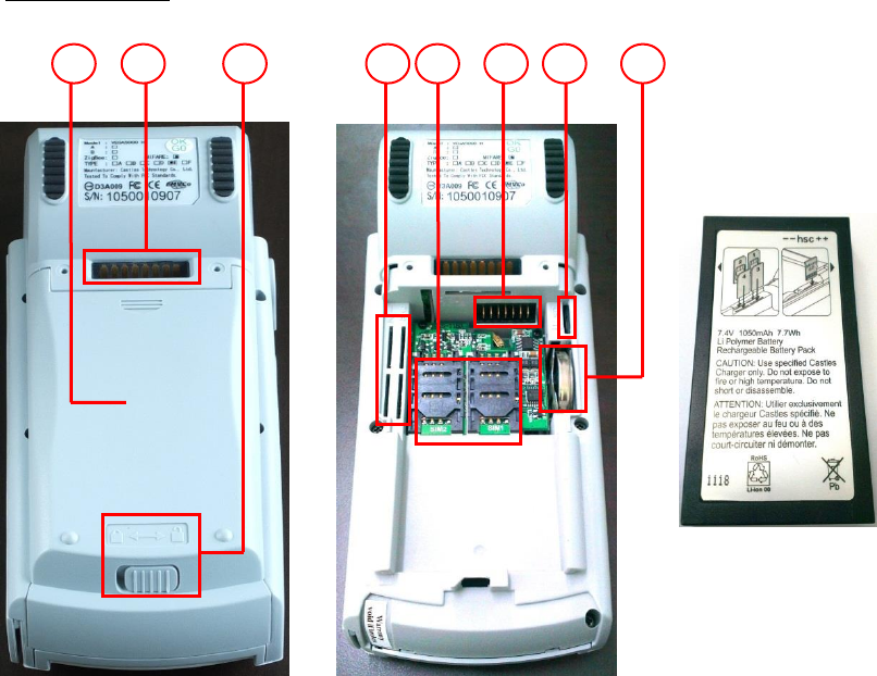
Rear (Portable)
14. Recharable Battery Cover
15. Battery Cover Lock
16. Base Connector
17. SAM Slots
18. Micro SD Card Slot
19. GSM SIM Card Slots
20. RTC Battery
21. Battery Connector
VEGA5000S
VEGA5000S
VEGA5000S
Rechargable
Battery
14
16
15
19
17
21
18
20
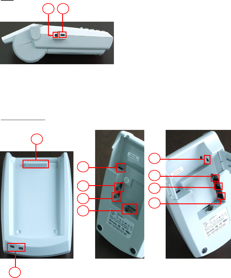
Side
22. Power Connector
23. USB Port
Base (Portable)
24. Base Connector
25. Base LED
26. Power Connector
27. Com port 1
28. Com port 2
29. Com port 3
30. Modem - Line Port
31. Modem – Tel Port
32. Ethernet Port
33. USB Port
VEGA5000S Portable
22
23
24
25
33
29
28
32
26
27
30
31
Castles Technology Co., Ltd. Confidential • All Right Reserved. Pg. 11
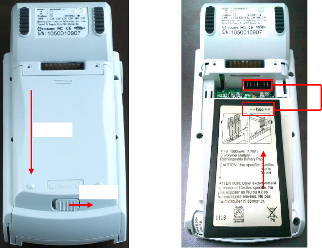
2.2. Inserting the Battery
Step 1: Unlock Battery cover
Step 2: Remove battery cover
Step 3: Insert battery into compament, battery contact point must align with
battery connector.
Align
Step 3
Step 2
Step 1
Castles Technology Co., Ltd. Confidential • All Right Reserved. Pg. 12
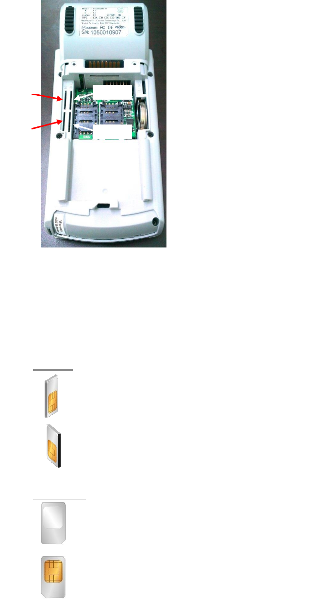
2.3. Inserting the SAM Card
Step 1: Remove battery cover / back cover
Step 2: Insert SAM card into desire slot.
Portable
SAM 1 & 2:
Gold contact at lower side of card and facing right.
SAM 3 & 4:
Gold contact at lower side of card and facing left.
Countertop
SAM 1 & 2 & 3:
Gold contact at upper side of card and facing down.
SAM 4 :
Gold contact at upper side of card and facing up.
VEGA5000S Portable
SAM1
SAM2
SAM3
SAM4
Castles Technology Co., Ltd. Confidential • All Right Reserved. Pg. 13
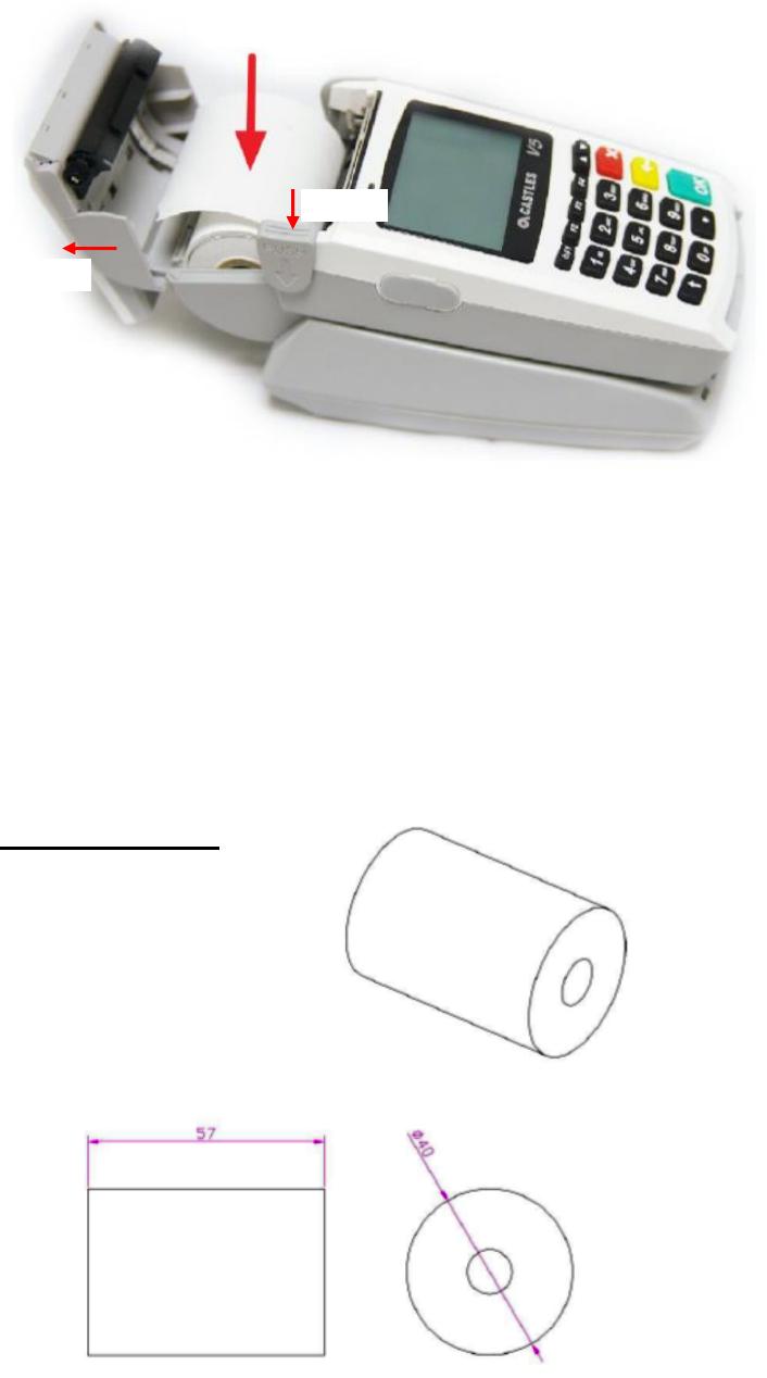
2.4. Inserting the Paper Roll
Step 1: Push paper roll box handle.
Step 2: Gentle open paper roll cover.
Step 3: Insert paper roll as direction showed.
Paper specification
Width: 57mm
Outside diameter: 40mm
Step 1
Step 2
Step 3
Castles Technology Co., Ltd. Confidential • All Right Reserved. Pg. 14
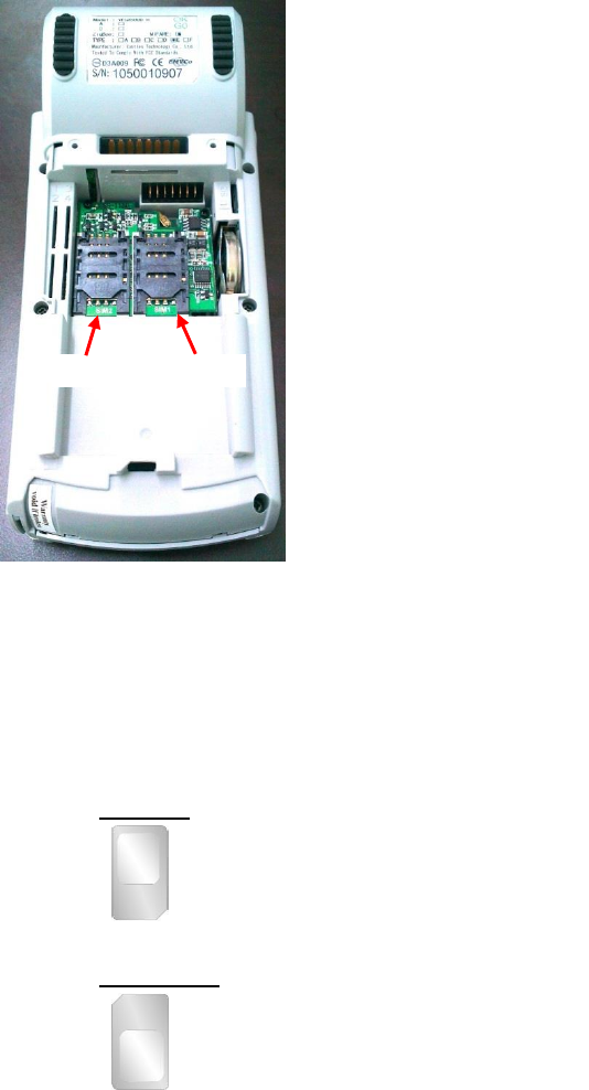
2.5. Inserting the GSM SIM Card
Step 1: Remove battery cover / back cover
Step 2: Open SIM socket and insert GSM SIM card into desire slot.
Portable
SIM 1 & 2:
Gold contact at upper side of card and facing down.
Countertop
SIM 1 & 2:
Gold contact at lower side of card and facing down.
SIM2
SIM1
VEGA5000S Portable
Castles Technology Co., Ltd. Confidential • All Right Reserved. Pg. 15
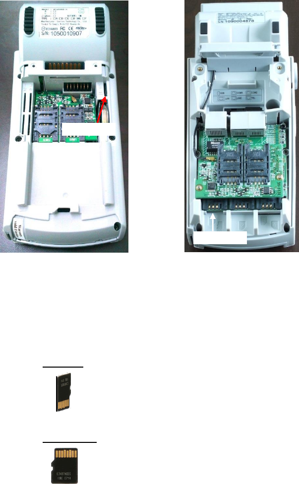
2.6. Inserting the Memory card
Step 1: Remove battery cover / back cover
Step 2: Insert Micro SD memory card.
Portable
Micro SD :
Gold contact at lower side of card and facing right.
Countertop
Micro SD :
Gold contact at upper side of card and facing up.
Micro SD
Micro SD
VEGA5000S Portable
VEGA5000S Countertop
Castles Technology Co., Ltd. Confidential • All Right Reserved. Pg. 16
3. Basic Operation
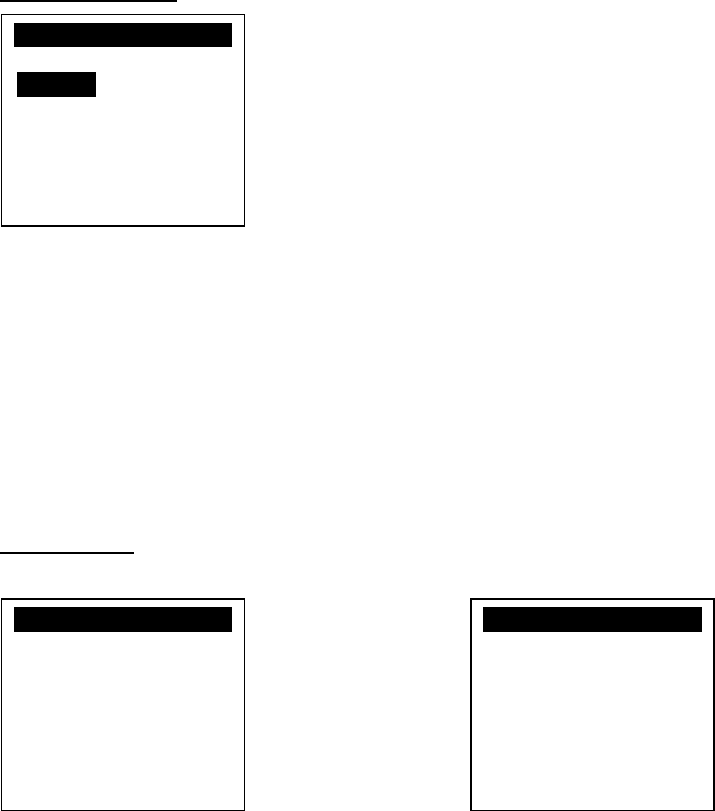
3.1. Program Manager
Upon power on, terminal will enter Program Manager if not default application
selected. All user applications are list in Program Manager. User may select an
application and run the application or view the application info, delete the
application or set to default run upon power on. User may enter System Menu to
configure terminal settings.
Program Manager
Press [F1] button to enter System Menu.
Press [F2] button to toggle default application selection.
Press [F3] button to delete application.
Press [F4] button to view application info.
Press [OK] button to run application.
Press [] or [] button to select application.
System Menu
Page 1 Page 2
Press [] button to page 2.
Program Manager
-----------01/02
1.App1
2.App2
F1:Download
System Menu
1.Download AP
2.System Info
3.Memory Status
4.Sys Settings
5.Test Utility
6.Factory Reset
7.Power Off
System Menu
1.FK PWD Change
2.Share objMng
3.Castles TMS
4.ULD KEY HASH

Castles Technology Co., Ltd. Confidential • All Right Reserved. Pg. 17
3.2. Download AP
Download user application or kernel modules firmware.
System Menu
Press [1] button to enter Download AP menu.
Download AP Menu
Select download source:
Press [1] button to select source as RS232 or USB connection and enter ULD
download mode.
Press [2] button to select source as USB disk.
Press [3] button to select source as SD card.
System Menu
1.Download AP
2.System Info
3.Memory Status
4.Sys Settings
5.Test Utility
6.Factory Reset
7.Power Off
Download EX
1.RS232 or USB
2.USB Disk
3.SD Card
Select DW Source
Castles Technology Co., Ltd. Confidential • All Right Reserved. Pg. 18
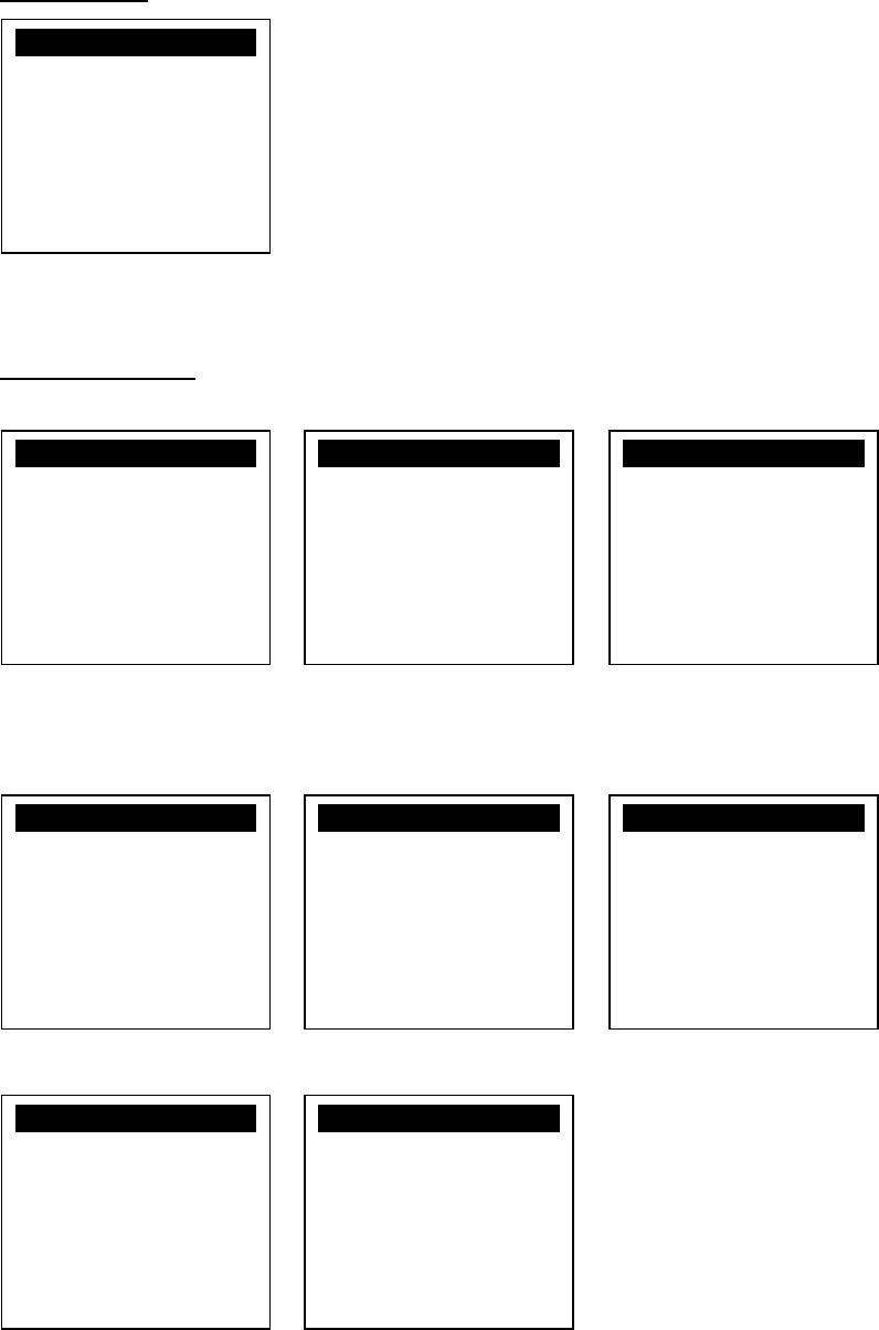
3.3. System Info
View kernel module firmware information.
System Menu
Press [2] button to enter System Info menu.
System Info Menu
Page 1 Page 2 Page 3
Press [OK] button to next page.
Page 4 Page 5 Page 6
Page 7 Page 8
System Menu
1.Download AP
2.System Info
3.Memory Status
4.Sys Settings
5.Test Utility
6.Factory Reset
7.Power Off
SYSTEM INFO
---Kernel Ver---
BOOTSULD : V0064
CRYPTOHAL: VF057
KMS : V0056
LINUXKNL : V0024
ROOTFS : V0050
SYSTEM INFO
--- KOVer ---
SECURITY : V0076
SYSUPD : V0080
KMODEM : N/A
DRV : V0089
USB : V0078
SC : V0083
SYSTEM INFO
--- SO Ver 1 ---
UART : V0072
USBH : V0070
MODEM : V0075
ETHERNET : V0078
FONT : V0076
LCD : V0073
SYSTEM INFO
--- SO Ver 2 ---
PRT : V0073
RTC : V0073
ULDPM : V0078
PPP MODEM: V0086
EMVL2 : V0072
KMS : V0073
SYSTEM INFO
--- SO Ver 3 ---
FS : V0075
GSM : V0080
BARCODE : V0073
TMS : V0072
TLS : V0071
CLVW : V0076
SYSTEM INFO
--- SO Ver 4 ---
CTOSAPI : V0083
SYSTEM INFO
--- HWMVer ---
CRDL/ETHE: V3004
CLM-MP : V0015
--- APVer ---
ULDPM : V0043
SYSTEM INFO
--- HWMVer ---
HUSBID:0CA6A050
CUSBID:N/A
--Factory S/N---
0000010600035717

Castles Technology Co., Ltd. Confidential • All Right Reserved. Pg. 19
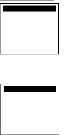
3.4. Memory Status
View terminal flash memory and RAM information.
System Menu
Press [3] button to enter Memory Status menu.
Memory Status Menu
System Menu
1.Download AP
2.System Info
3.Memory Status
4.Sys Settings
5.Test Utility
6.Factory Reset
7.Power Off
MEMORY STATUS
--FLASH Memory--
Total: 31616KB
Used : 22640KB
--SDRAM Memory--
Total: 31872KB
Used : 10908KB

Castles Technology Co., Ltd. Confidential • All Right Reserved. Pg. 20
3.5. System Settings
View or change terminal system settings.
Setting
Descriptions
Key Sound
Enable (Y) or disable (N) the beep sound when
pressing any key.
Exec DFLT AP
Enable (Y) or disable (N) execution of default
selected application.
USB CDC Mode
Enable (Y) or disable (N) USB CDC mode.
FunKey PWD
Enable (Y) or disable (N) password protection to
access function key (F1 ~ F4) in Program Manager.
PMEnter PWD
Enable (Y) or disable (N) password protection to
enter Program Manager.
SET USB Host
Enable (Y) or disable (N) USB host mode.
Base USB CDC
Enable (Y) or disable (N) USB CDC mode in base
unit. [Portable model only]
List SHR Lib
Enable (Y) or disable (N) to list all shared libraries in
Program Manager.
Key MNG Mode
<TBC>
Bat Threshld
Battery charging threshold value. [Portable model
only]
Null Cradle
Enable (Y) if base is null cradle. [Portable model
only]
Debug Mode
Enable (Y) or disable (N) console debug mode.
Debug Port
Serial port for console debug.
Mobil AutoON
<TBC>
GDB Mode
Enable (Y) or disable (N) GDB mode. [VEGA5000S
only]
GDB Timeout
GDB connection timeout. [VEGA5000S only]
GDB Channel
GDB connection channel. [VEGA5000S only]
ETHER IP/PORT
GDB Ethernet connection setting. [VEGA5000S
only]

Castles Technology Co., Ltd. Confidential • All Right Reserved. Pg. 21
System Menu
Press [4] button to enter System Settings menu.
System Settings Menu
Page 1
Press [] or [] button to select setting.
Press [OK] button to change the setting value.
Press [] button to toggle Y N Y.
Press [F3] button to next page.
Page 2
Press [] or [] button to select setting.
Press [OK] button to change the setting value.
Press [] button to toggle Y N Y.
Press [F2] button to previous page.
Press [F3] button to next page.
System Menu
1.Download AP
2.System Info
3.Memory Status
4.Sys Settings
5.Test Utility
6.Factory Reset
7.Power Off
SYS SETTINGS
Key Sound : Y
Exec DFLT AP: Y
-AP Name
USB CDC Mode: Y
FunKeyPWD : N
PMEnterPWD : N
F3: Next Page
SYS SETTINGS
SET USB Host: N
Base USB CDC: X
List SHR Lib: N
Key MNG Mode: 0
Bat Threshld: X
Null Cradle : X
F2:Prev F3:Next

Castles Technology Co., Ltd. Confidential • All Right Reserved. Pg. 22
Page 3
Press [] button to select setting.
Press [OK] button to change the setting value.
Press [] button to toggle Y N Y.
Press [F2] button to previous page.
Press [F3] button to next page.
Page 4 (VEGA5000S only)
Press [] button to select setting.
Press [OK] button to change the setting value.
Press [] button to toggle Y N Y.
Press [F2] button to previous page.
SYS SETTINGS
Debug Mode : N
Debug Port : X
Mobil AutoON: Y
F2:Prev F3:Next
SYS SETTINGS
GDB Mode : Y
GDB Timeout: 60s
GDB Channel : E
ETHER IP/PORT
192.120.100.222
5000
F2:Prev Page

Castles Technology Co., Ltd. Confidential • All Right Reserved. Pg. 23
3.6. Test Utility
Perform terminal hardware components diagnostic.
System Menu
Press [5] button to enter Test Utility menu.
Test Utility Menu
Page 1
Press [1] button to diagnose LCD.
Press [2] button to diagnose keyboard.
Press [3] button to diagnose flash memory.
Press [4] button to diagnose smart card module.
Press [5] button to diagnose backlight.
Press [6] button to diagnose magnetic stripe reader.
Press [7] button to diagnose LED.
Press [8] button to diagnose real time clock.
Press [9] button to diagnose printer.
Press [0] button to view font.
Press [F2] button to enter Communication Test Menu.
Press [F3] button to power off.
Press [] button to next page.
Note: Default password for changing RTC is 8418.
System Menu
1.Download AP
2.System Info
3.Memory Status
4.Sys Settings
5.Test Utility
6.Factory Reset
7.Power Off
Main Menu 0009
1:LCD 2:KBD
3:FLASH 4:SCM
5:Light 6:MSR
7:LED 8:RTC
9:PRNTR 0:FONT
[F2]Comm Menu
[F3]Power Off

Castles Technology Co., Ltd. Confidential • All Right Reserved. Pg. 24
Page 2
Press [1] button to diagnose contactless reader in transparent mode.
Press [2] button to diagnose contactless card.
Press [3] button to diagnose SD memory card.
Press [] button to previous page.
Press [X] button to exit.
Communication Test Menu
Press [1] button to diagnose Com 1.
Press [2] button to diagnose Com 2.
Press [3] button to diagnose Com 3.
Press [4] button to diagnose Ethernet module.
Press [5] button to diagnose USB.
Press [6] button to diagnose modem.
Press [7] button to diagnose GPRS.
Press [8] button to diagnose all, item 1 to 7.
Main Menu
1:CL_Transparent
2:CL Card Test
3:SD Card Test
:PAGE1 X:EXIT
Communicate Test
1. COM1 2. Com2
3. Com3
4. Ethernet Test
5. USB Test
6. Modem Test
7. GPRS Test
8. All Test

Castles Technology Co., Ltd. Confidential • All Right Reserved. Pg. 25
3.7. Factory Reset
Perform factory reset, all user application, fonts and data will be deleted.
System Menu
Press [6] button to enter Factory Reset menu.
Factory Reset Menu
Press [OK] button to perform factory reset.
Enter factory reset password.Default password: 8418
System Menu
1.Download AP
2.System Info
3.Memory Status
4.Sys Settings
5.Test Utility
6.Factory Reset
7.Power Off
Factory Reset
OK to reset ?
Factory Reset
Password :
****

Castles Technology Co., Ltd. Confidential • All Right Reserved. Pg. 26
3.8. Power Off
Power off terminal.
System Menu
Press [7] button to power off terminal.
System Menu
1.Download AP
2.System Info
3.Memory Status
4.Sys Settings
5.Test Utility
6.Factory Reset
7.Power Off

Castles Technology Co., Ltd. Confidential • All Right Reserved. Pg. 27
3.9. Function Key Password Change
Change function key access password.
System Menu (Page 2)
Press [1] button to enter FunKey Password menu.
FunKey Password Menu
Enter current password. (Default password is "0000")
Enter new password.
Enter new password again to confirm.
System Menu
1.FK PWD Change
2.Share objMng
3.Castles TMS
4.ULD KEY HASH
FunKey Password
Enter Password:
****
FunKey Password
New Password:
****
Confirm Password
****
FunKey Password
New Password:
****
Confirm Password
****
PWD Changed OK
Castles Technology Co., Ltd. Confidential • All Right Reserved. Pg. 28
3.10. Share Object Management
View share object in terminal.
System Menu (Page 2)
Press [2] button to enter Share Object Management menu.
Share Object Management Menu
Press [1] button to view shared library.
Press [2] button to view shared file.
System Menu
1.FK PWD Change
2.Share objMng
3.Castles TMS
4.ULD KEY HASH
Share objMng
1.Share LIB
2.Share File

Castles Technology Co., Ltd. Confidential • All Right Reserved. Pg. 29
3.11. CTOS TMS
Connect to TMS (Terminal Management Softare) server, set or delete TMS
configuration.
System Menu (Page 2)
Press [3] button to enter Castles TMS menu.
Castles TMS Menu
Press [1] button to connect to TMS server.
Press [2] button to set TMS configuration.
Press [3] button to delete TMS configuration.
System Menu
1.FK PWD Change
2.Share objMng
3.Castles TMS
4.ULD KEY HASH
CASTLES TMS
1.Connect Server
2.SetConfig
3.DelConfig

Castles Technology Co., Ltd. Confidential • All Right Reserved. Pg. 30
3.12. ULD Key Hash
View ULD user keyset hash value.
System Menu (Page 2)
Press [4] button to view hash value.
System Menu
1.FK PWD Change
2.Share objMng
3.Castles TMS
4.ULD KEY HASH
USER ENC KEY
9572BC621C1D5406
0856D00BCC207000
D3320077
USER SIGN KEY
A927768EA7DD7B9E
7E3F395C10726B6F
43B35C5A

Castles Technology Co., Ltd. Confidential • All Right Reserved. Pg. 31
4. Secure File Loading
Castles implemented an interface in terminal named User Loader(ULD) to provide secure file
loading to system memory. Loading of user application, kernel firmware, font and others
must use User Loader.
The loading process is secure by signing the files using ULD Key System.
4.1. ULD Key System
The ULD Key System uses two key sets for securely managing the kernel
updating and application downloading. Each key set contains two RSA key pairs.
One is used for key encryption and the other is used for signature. These two key
sets are specified as below:
ULD Manufacturer Key Set
ULD Manufacturer Key Encryption Key (RSA)
ULD Manufacturer Signature Key (RSA)
ULD User Key Set
ULD User Key Encryption Key (RSA)
ULD User Signature Key (RSA)
For VEGA5000S, the RSA key length is 2048bits.
4.1.1. ULD Manufacturer Key
The system consists of several kernel modules. These kernel modules
are provided by the Manufacturer, and released in CAP format file with
encryption and signing via ULD Manufacturer Keys.
The ULD Manufacturer keys are managed and maintained by the
manufacturer. The manufacturer uses these keys to generate kernel
CAP files for updating the system. However, the system is not permited
to be updated with these kernel CAP files directly generated by the
manufacturer. This is because only the user can have the privilege to
decide whether the system is to be updated. Therefore, before system
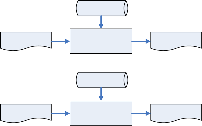
Castles Technology Co., Ltd. Confidential • All Right Reserved. Pg. 32
updating, the kernel CAP files must be “signed” via ULD User Key to get
the user permission. For simple expression, we call the kernel CAP files
generated by the manufacturer as “unsigned kernel CAP(s)” and call the
kernel CAP files “signed” by the user later as “signed kenel CAP(s)”.
Notes:
1. Tthe kernel modules are encrypted by a random-generated 3DES
key, which is retrieved from the Key Encryption Block of the CAP by
ULD Manufacturer Key Encryption Key, not directly encrypted by ULD
RSA Key.
2. The “sign” action via ULD User Keys actually is done by” the second
encryption”. “The second encryption” is done by using the random-
generated 3DES key, which is encrypted by ULD User Key Encryption
Key, to perform Triple DES encryption again on the cipher data segment
of the kernel CAP files. This ensures that the system cannot retrieve the
correct data from the kernel CAPs without the user permission.
CAP Generator
Kernel Module
ULD Manufacturer
Keys
Unsigned Kernel
CAPs
Unsigned Kernel
CAPs CAP Signing Tool Signed Kernel CAPs
ULD User Keys
Castles Technology Co., Ltd. Confidential • All Right Reserved. Pg. 33
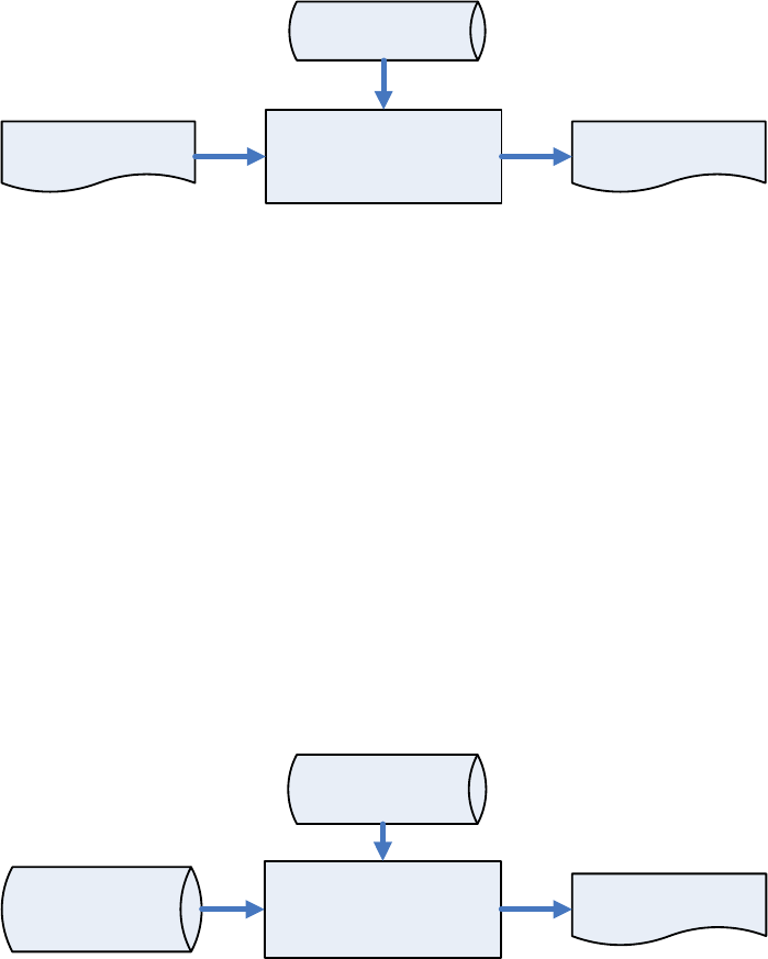
4.1.2. ULD User Key
ULD User Key are used to encrypt and sign the user/shared
applications. In addition, they are as goalkeepers to prevent the system
updating without user permission. This is done by the kernel CAPs
which are encrypted and signed by the manufacturer having to perform
the “signed’ action via ULD User Keys.
Notes: Applications are encrypted by a random-generated 3DES key,
which is retrieved from the Key Encryption Block of the CAP by ULD
User Key Encryption Key, not directly encrypted by ULD RSA Key.
Application Application CAPs
ULD User Keys
CAP Generator
4.1.3. Key Change
The ULD RSA Keys are able to be changed. The system uses a special
CAP file, KEY CAP, for the manufacturer and user to change their own
keys. The KEY CAP contains a new set of ULD keys (Key Encryption
Key and Signature Key). These new keys are encrypted and signed via
the original keys. In other words, if the user would like to change the
ULD User Keys, they have to use their original ULD User Keys with the
new ULD User Keys to generate a KEY CAP.
Key CAP Generator
Original ULD
Manufacturer/User
Keys
New ULD
Manufacturer/User
Keys
User KEY CAP
Castles Technology Co., Ltd. Confidential • All Right Reserved. Pg. 34
4.2. File Signing
4.2.1. Signing Kernel Module
Castles will release new version of kernel module in “unsigned” form.
This files required to sign with ULD User Key before it can load to
terminal.
Castles Technology provided a tool named “CAP Signing Tool” to
perform this task.
The CAP Signing Tool is located at:
VEGA5000S
C:\Program Files\Castles\VEGA5000S\tools\Signing Tool
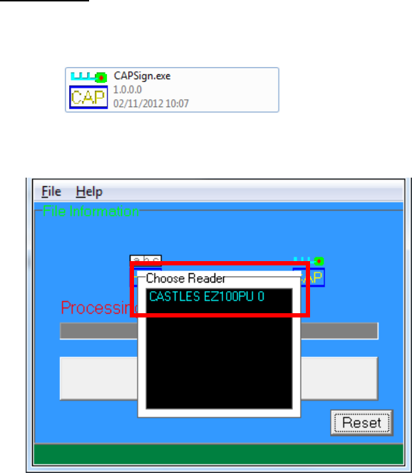
Run CAP Signing Tool
(VEGA5000S)
Insert Key Card and select smart card reader
Castles Technology Co., Ltd. Confidential • All Right Reserved. Pg. 35
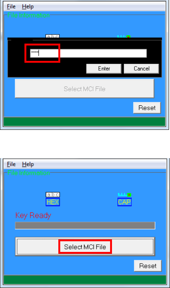
Enter Key Card PIN
CAP Signing Tool is ready, press “Select MCI File” button to browse
the file.
Output file will be located in “signed” folder.
Castles Technology Co., Ltd. Confidential • All Right Reserved. Pg. 36
4.2.2. Signing User Files
Following files are required to sign before load to terminal. This is to
ensure the application data and codes confidential and integrity. The
output fille will be “CAP” file which is file format defined by Castles.
User application
User application data files
User application library
Font file
Share library
Share files
System setting
Key CAP (Manufacturer ULD Key Set)
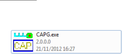
Castles Technology provided a tool named “CAP Generator” to perform
this task.
The CAP Generator is located at:
VEGA5000S
C:\Program Files\Castles\VEGA5000S\tools\CAPG (KeyCard)
Run CAP Generator
Castles Technology Co., Ltd. Confidential • All Right Reserved. Pg. 37
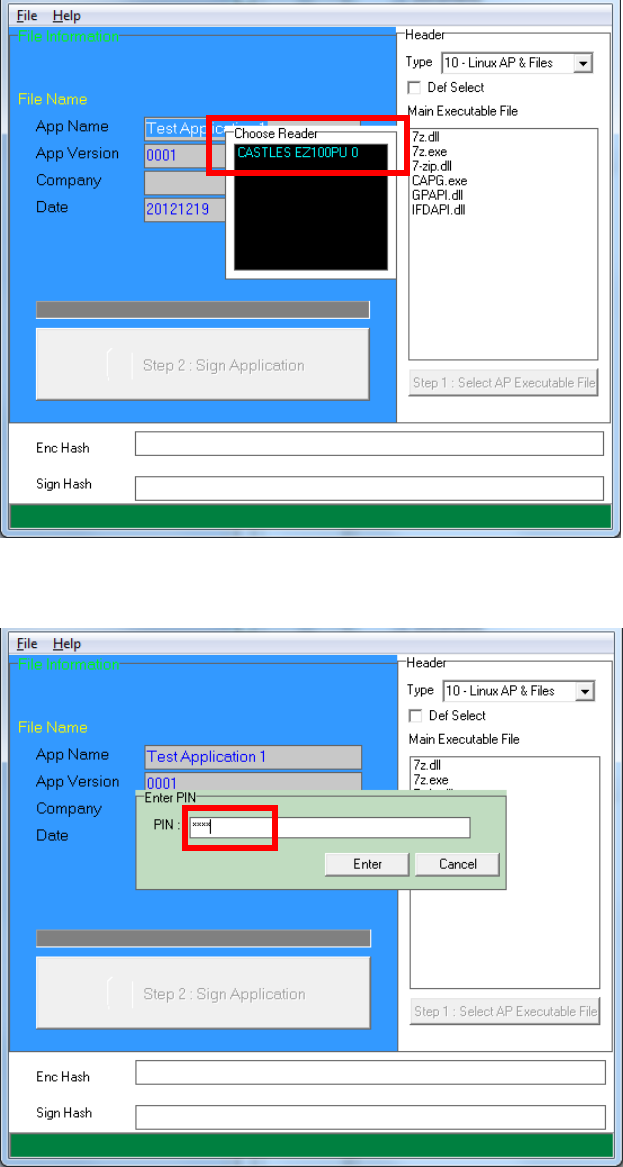
Insert Key Card and select smart card reader
Enter Key Card PIN
Castles Technology Co., Ltd. Confidential • All Right Reserved. Pg. 38
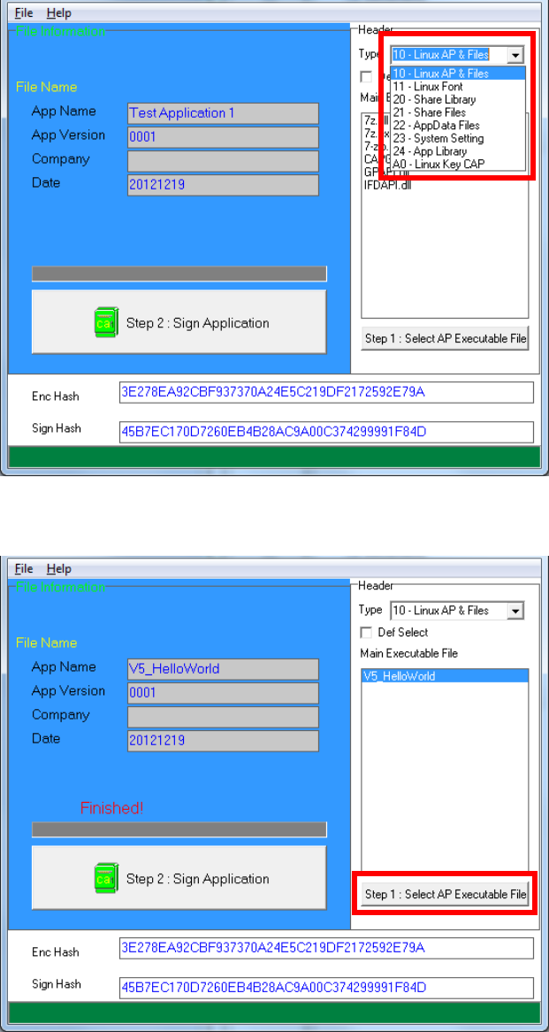
CAP Generator is ready, select the correct Type from the list.
Press “Step 1: Select AP Executable File” to select file to sign. This
is valid for all the files to sign.
Castles Technology Co., Ltd. Confidential • All Right Reserved. Pg. 39
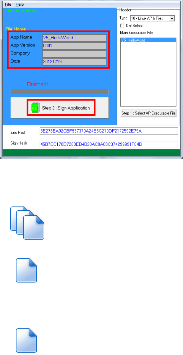
Enter file details and press “Step 2: Sign Application” to sign the file.
This is valid for all the files to sign.
The output file will be in a set. A “mci” file with one or more “CAP”
files.CAP file contents the signed file binaries, where MCI file
contents the list of CAP files.
Note: If user would like to load multiple set of signed file, create a new
file with extension of “mmci”. Then put the mmci file contents with the list
of mci file.
App.CAP
App.mci
MultiApp.mmci
Castles Technology Co., Ltd. Confidential • All Right Reserved. Pg. 40
4.3. File Loading
There are several ways of loading file to VEGA5000S terminal.
Download by User Loader
Download by removable media
Download by user application
Download by Castles TMS
User Loader is a tool provided by Castles Technology. It’s the formal way to
download file to terminal.
User may implement their own ways of updating application or files using CTOS
API provided, CTOS_UpdateFromMMCI().
Castles TMS (CTMS or CASTLES Terminal Management System) is provided by
Castles Technology. It’s use to perform remote download via Ethernet,
GPRS/UMTS or modem.
4.3.1. Download by User Loader
The Loader is located at:
VEGA5000S
C:\Program Files\Castles\VEGA5000S\tools\Loader
Run User Loader
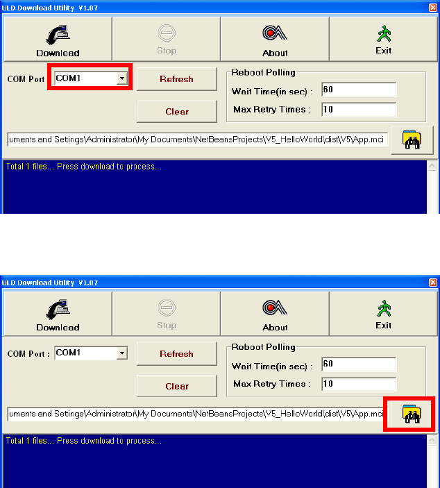
Castles Technology Co., Ltd. Confidential • All Right Reserved. Pg. 41
Select COM port
Browse and select mci file or mmci file
Setup terminal to enter download mode
Press [F1] button in Program Manager (PM)
Press [1] button to select “1. Download AP“
Press [1] button again to select download via RS232 or USB
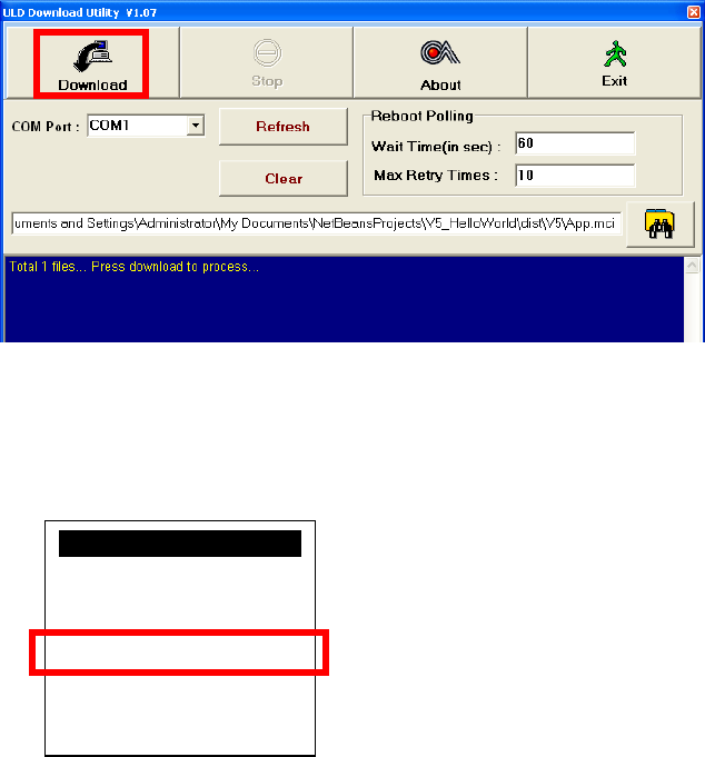
Castles Technology Co., Ltd. Confidential • All Right Reserved. Pg. 42
Press “Download” button to start.
Note: To download using USB cable, terminal must enable CDC mode.
Set USB CDC Mode to Y.
SYS SETTINGS
Key Sound : Y
Exec DFLT AP: Y
-AP Name
USB CDC Mode: Y
FunKeyPWD : N
PMEnterPWD : N
F3: Next Page
Castles Technology Co., Ltd. Confidential • All Right Reserved. Pg. 43
4.3.2. Download by Removable Media
The file download process can be achieved without PC by using
removable media, USB flash drive or MicroSD memory card. We
recommend don’t put unwanted file to removable media, as it will
increase the time during detection.
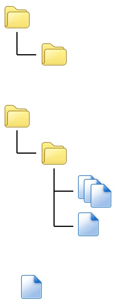
Create a folder name “vxupdate” under root directory.
Place the mci file and cap file to “vxupdate” folder.
Note: If user would like to load multiple application, create a new file
with extension of “mmci”. Then put the mmci file contents with the
list of mci file.
root
vxupdate
root
vxupdate
App.CAP
App.mci
MultiApp.mmci

Castles Technology Co., Ltd. Confidential • All Right Reserved. Pg. 44
Insert removable media to terminal, and select the removable media
type in “Download AP” menu.
Download AP Menu
o Press [2] button to select USB flash drive.
o Press [3] button to select MicroSD card.
Finally, terminal will process the file “vxupdate” folder.
Download EX
1.RS232 or USB
2.USB Disk
3.SD Card
Select DW Source
Castles Technology Co., Ltd. Confidential • All Right Reserved. Pg. 45
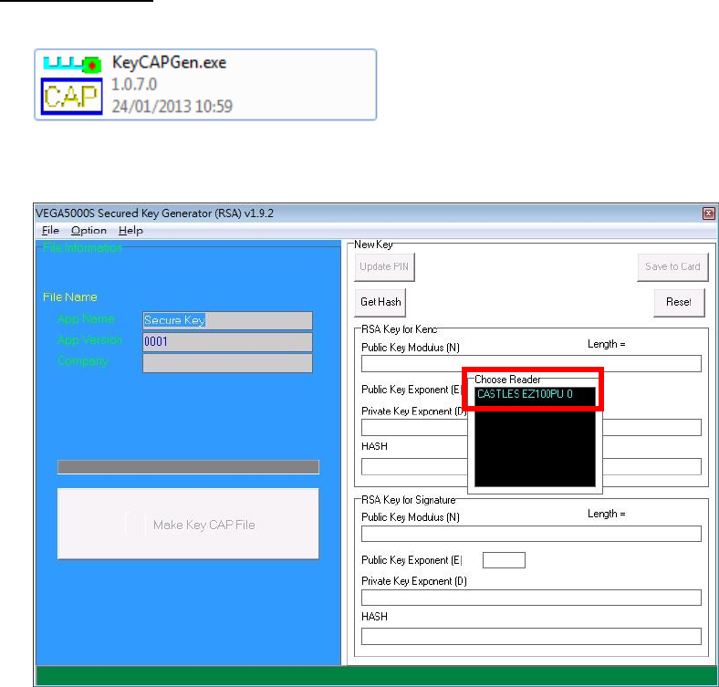
4.4. Changing ULD User Key
User may change their ULD User Key Set stored in Key Card. Castles
Technology provided a tool named “Secure Key Generator” to perform this task.
For VEGA5000S
Run Secure Key Generator
Insert Key Card and select smart card reader
Enter Key Card PIN, default PIN is “1234”.
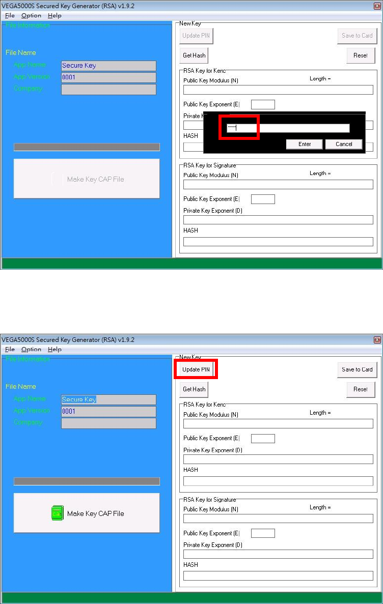
Castles Technology Co., Ltd. Confidential • All Right Reserved. Pg. 46
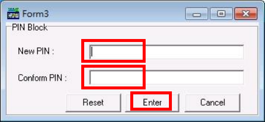
To change Key Card PIN, press “Update PIN” button. If not, please skip this
steps.
o Enter new PIN, enter new PIN again to confirm, then press [Enter] button
to change PIN in Key Card.
Castles Technology Co., Ltd. Confidential • All Right Reserved. Pg. 47
Castles Technology Co., Ltd. Confidential • All Right Reserved. Pg. 48
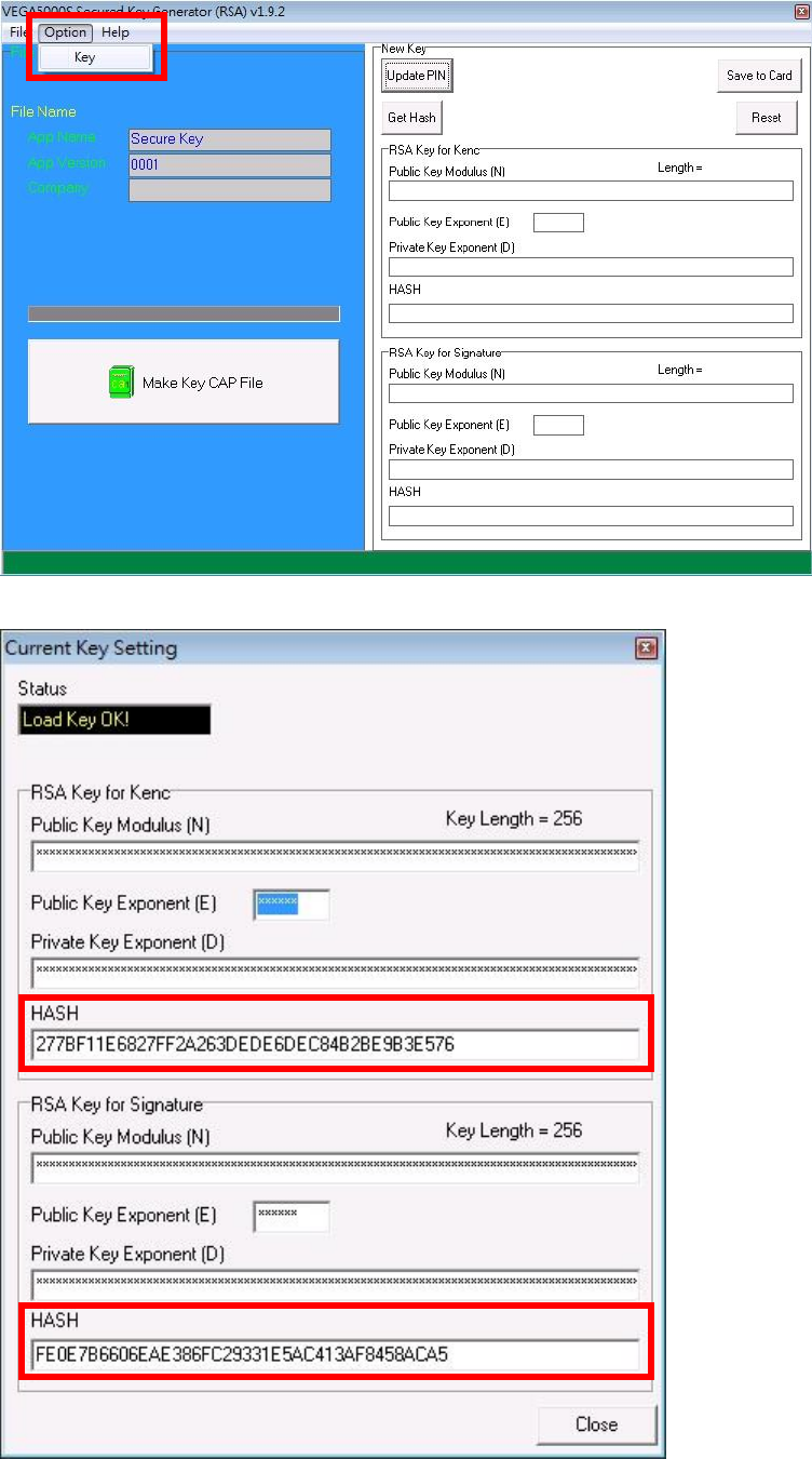
To view current key set hash value, goto “Option” and select key.
Castles Technology Co., Ltd. Confidential • All Right Reserved. Pg. 49
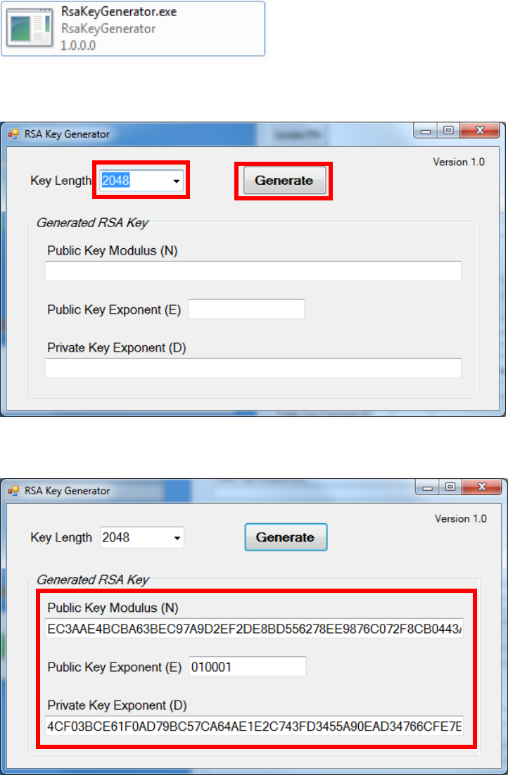
To generate new user key set
o Run RSA Key Generator
o Select Key Length as 2048 (bits), then press [Generate] button to
generate the RSA key set.
Result:
Castles Technology Co., Ltd. Confidential • All Right Reserved. Pg. 50
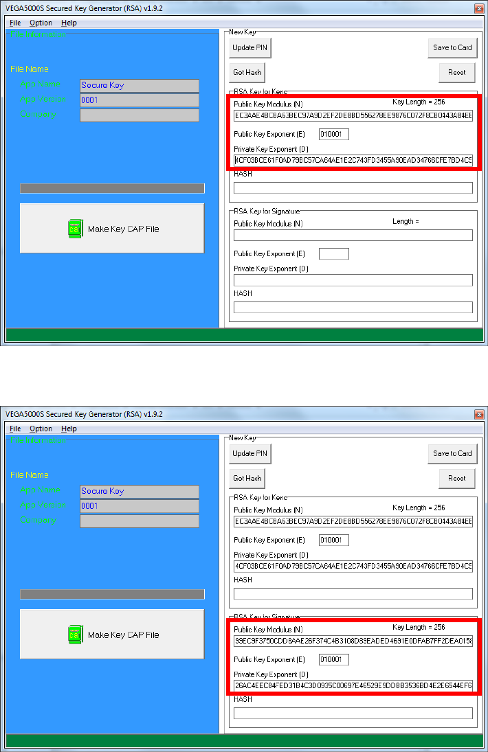
o Copy RSA key components to RSA Key for Kenc in Secure Key
Generator.
o Generate second RSA key set for Signature.
Castles Technology Co., Ltd. Confidential • All Right Reserved. Pg. 51
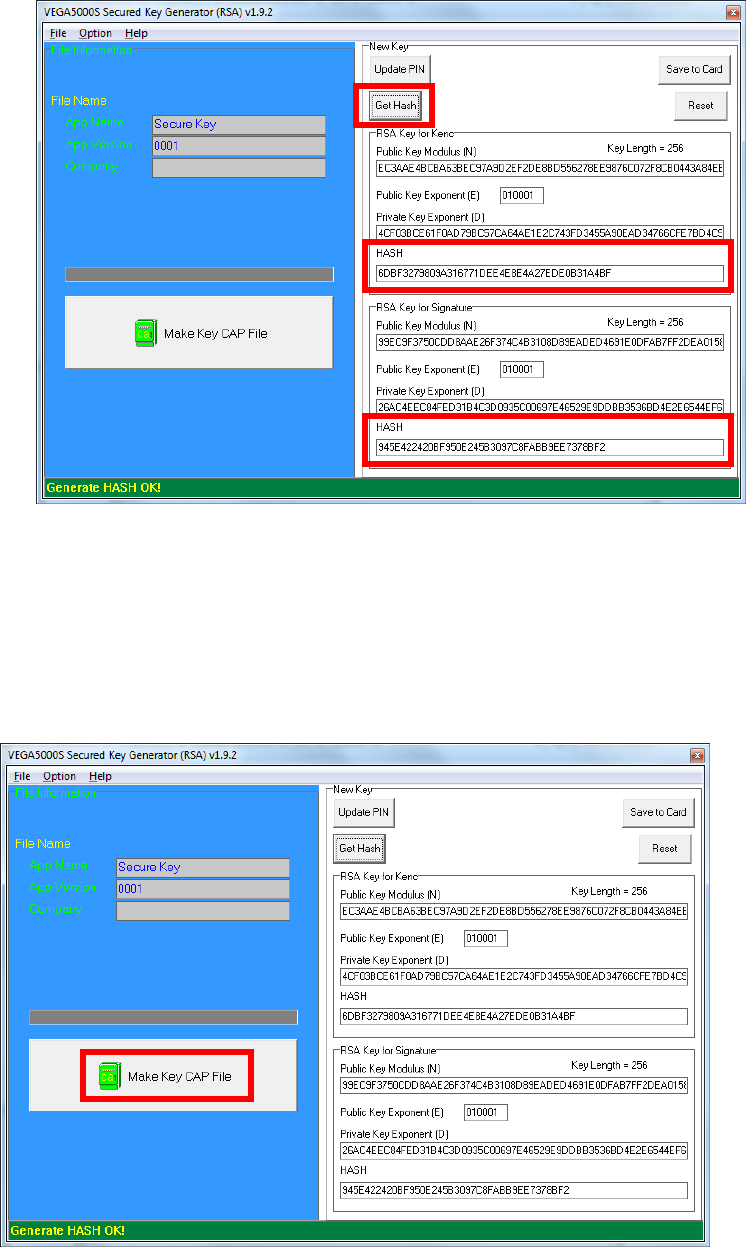
o Click [Get Hash] button to calculate the hash value for key sets.
o Please copy down all the values into a text file and keep in a safe place.
You will need this if you need to create duplicate Key Card.
To generate the key CAP for the newly generated user key set, press [Make
Key CAP File] button.
Castles Technology Co., Ltd. Confidential • All Right Reserved. Pg. 52
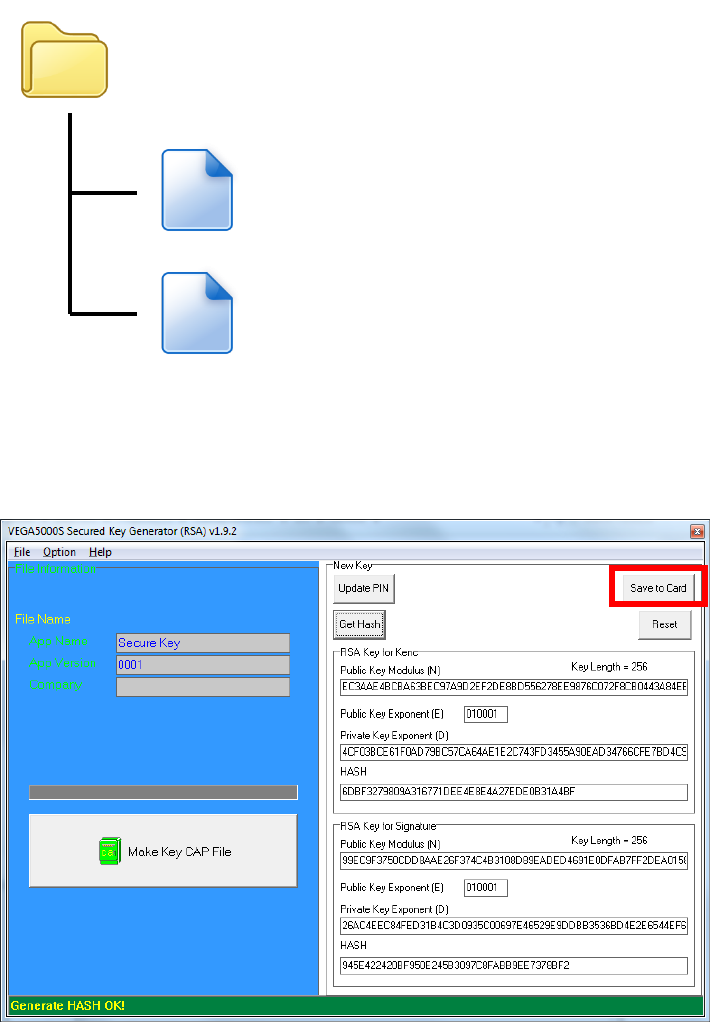
The output file will be located in the Secure Key Generator folder.
To update the newly generated key set to Key Card, press [Save to Card]
button to write the key set to Key Card.
SecureKeyGenerator
key.mci
key.cap
Castles Technology Co., Ltd. Confidential • All Right Reserved. Pg. 53
5. Font Management
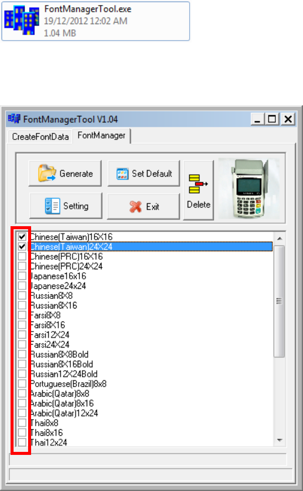
5.1. Loading New Font
Run FontManager.exe
Located at C:\Program Files\Castles\Font Manager
Select font to download
Castles Technology Co., Ltd. Confidential • All Right Reserved. Pg. 54
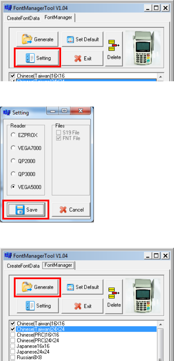
Press [Setting] button to configure terminal type.
Select VEGA5000, press [Save] button to save and return font manager.
Press [Generate] to create the font file.
Castles Technology Co., Ltd. Confidential • All Right Reserved. Pg. 55
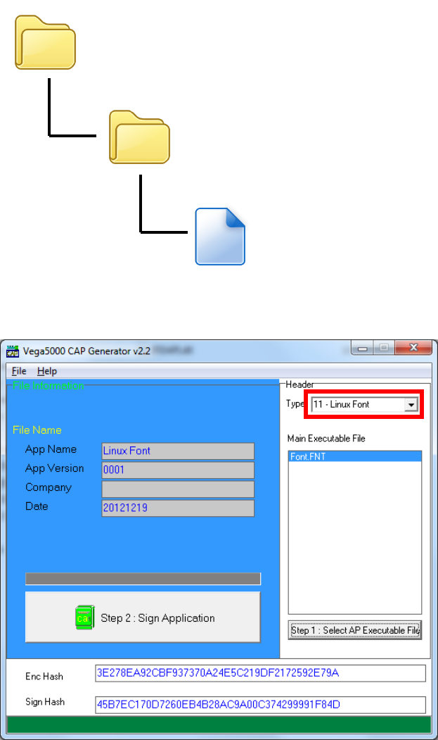
Output file “Font.FNT” will be located at sub-directory named “Font” in “Font
Manager” folder.
Sign the file using CAP Generator, the type must set to “11 – Linux Font”.
Lastly, download the signed file (CAP file) to terminal using Loader.
Font Manager
Font
Font.FNT
Castles Technology Co., Ltd. Confidential • All Right Reserved. Pg. 56
5.2. Custom Font
User may create font they preferred for displaying or printing on terminal.
There are two zone defined:
Zone 0x00 ~ 0x7F – ASCII characters, you may replace with the font type
preferred or your own language character set.
Zone 0x80 ~ 0xFF – Free to use, you may use for symbols.
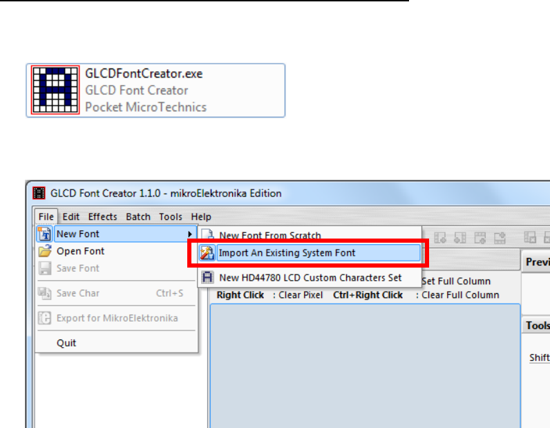
Following steps demonstrate how to create a 12x24 font.
Run GLCD Font Creator
Select [File] [New Font] [Import An Existing System Font]
Castles Technology Co., Ltd. Confidential • All Right Reserved. Pg. 57
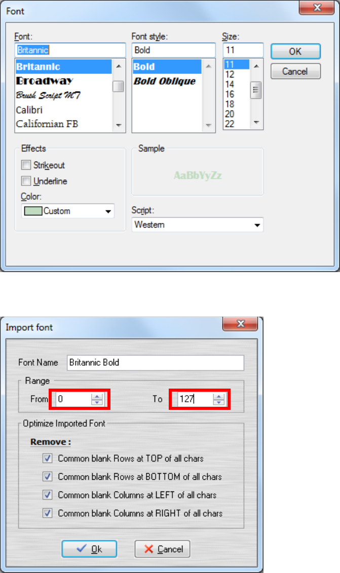
Select the font needed, simply choose a font size. The final value of font size
should be determine by the minimum pixel width. You may need to repeat this
steps few times to find the best fit font size.
Set the import range from 0 to 127.
Castles Technology Co., Ltd. Confidential • All Right Reserved. Pg. 58
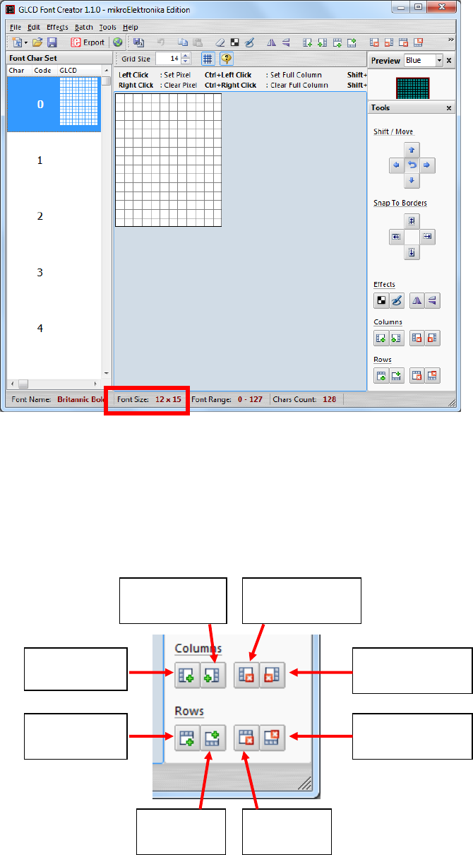
Check the minimum pixel width and height.
If the pixel width of the font size is larger than expected, then you have to
repeat the previous steps to import font with smaller size.
Use the following buttons to adjust the font size to match with expected font
size.
Add row on
top
Add row
on bottom
Remove
row on top
Remove row
on bottom
Add column
on left
Add
columnonrigh
t
Removecolum
nonleft
Removecolumn
onright
Castles Technology Co., Ltd. Confidential • All Right Reserved. Pg. 59
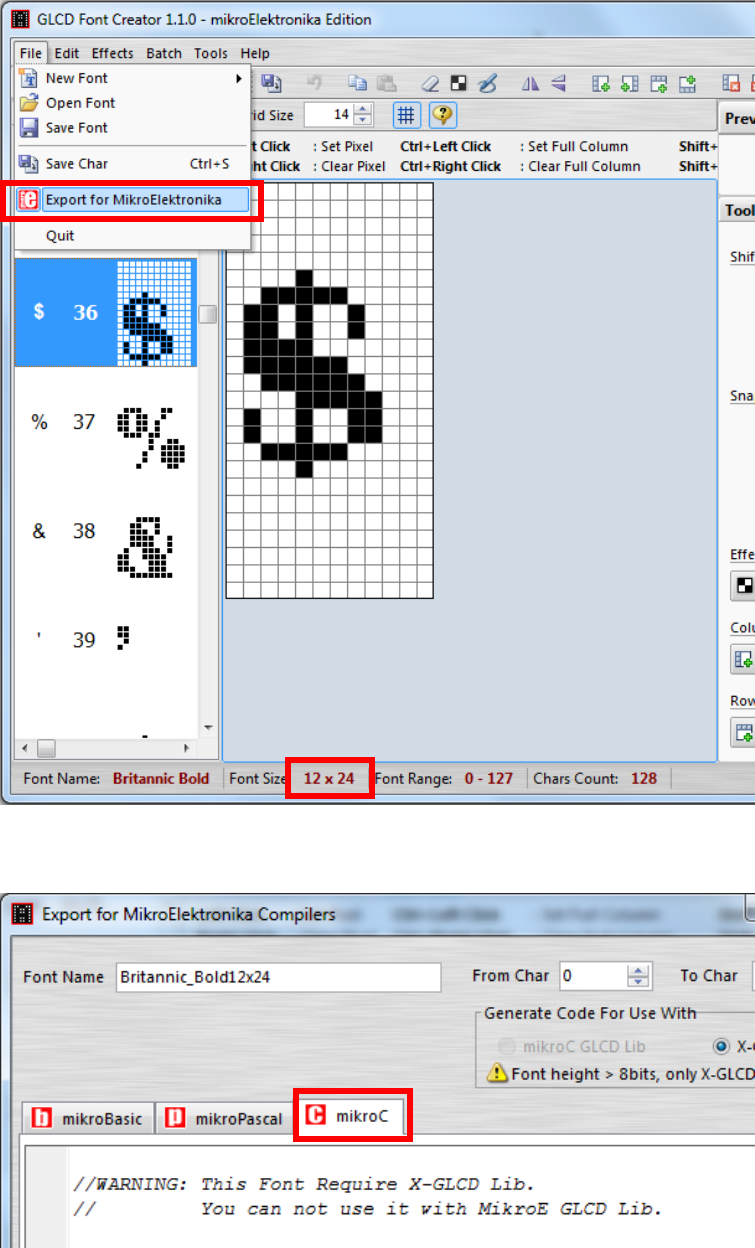
After adjust font size, select [File] [Export for MicroElektronika].
Select output format as [mikroC].
Castles Technology Co., Ltd. Confidential • All Right Reserved. Pg. 60
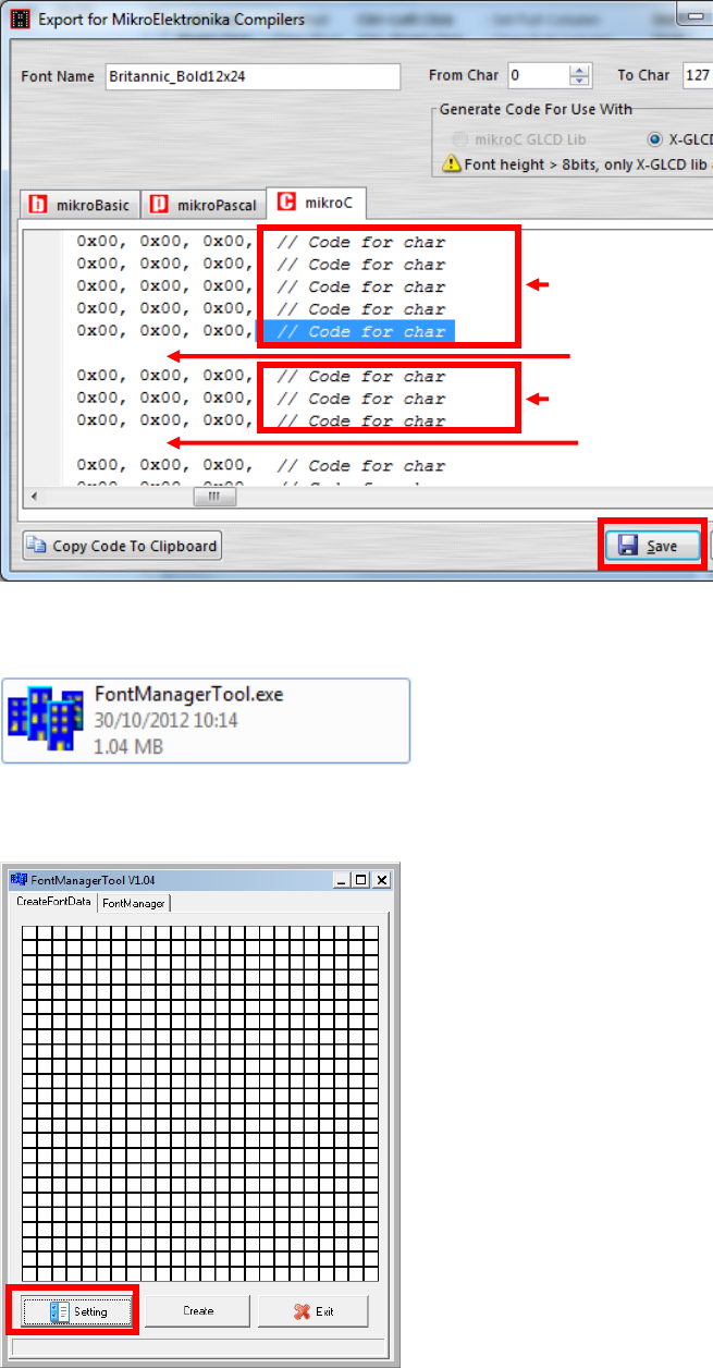
Remove comment “// Code for char “ from offset 0x00 to 0x1F. Remove
empty line if found. Then click [Save] button to save to file.
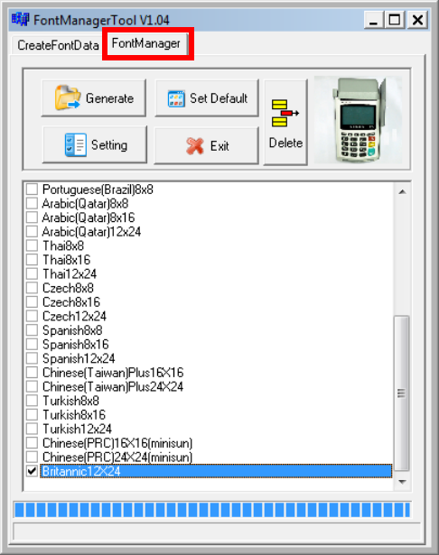
Run Font Manager Tool.
Click [Setting] button
Remove
Remove
Remove
Remove
Castles Technology Co., Ltd. Confidential • All Right Reserved. Pg. 61
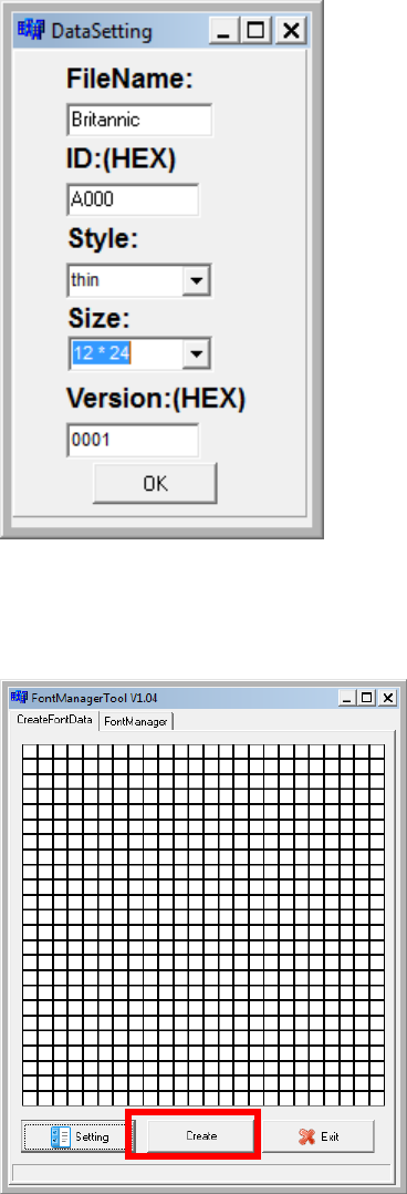
Enter the file name, font id, and select the size.
Click [Create] button, and select the C file previously created using GLCD
Font Generator.
Castles Technology Co., Ltd. Confidential • All Right Reserved. Pg. 62
Select [Font Manager] tab and tick the newly creately font, and press
[Generate] button to export to FNT file.
Castles Technology Co., Ltd. Confidential • All Right Reserved. Pg. 63
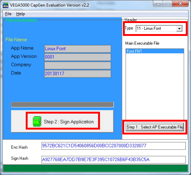
Use CAP Generator to conver the FNT file to CAP.
Set type to [11 – Linux Font], press [Step 1] button select the FNT file. Then
press [Step 2] to generate CAP file.
Download the font CAP file to terminal.
In terminal application, add following code to display message using the
newly created font.
CTOS_LanguageConfig(0xA000,d_FONT_12x24,0,d_FALSE);
CTOS_LanguageLCDSelectASCII(0xA000);
CTOS_LCDTPrintXY(1, 1, "ABCDEFGH");
Or print message using the newly created font.
CTOS_LanguagePrinterSelectASCII(0xA000);
CTOS_PrinterPutString("ABCDEFGH");
Castles Technology Co., Ltd. Confidential • All Right Reserved. Pg. 64
5.3. Using TrueType Font (TTF)
TrueType Font (TTF) is only supported in VEGA5000S terminal.You may
download the TrueType font preferred to terminal for displaying or printing.
Following steps demonstrate how to use “Cooper Black” True Type font.
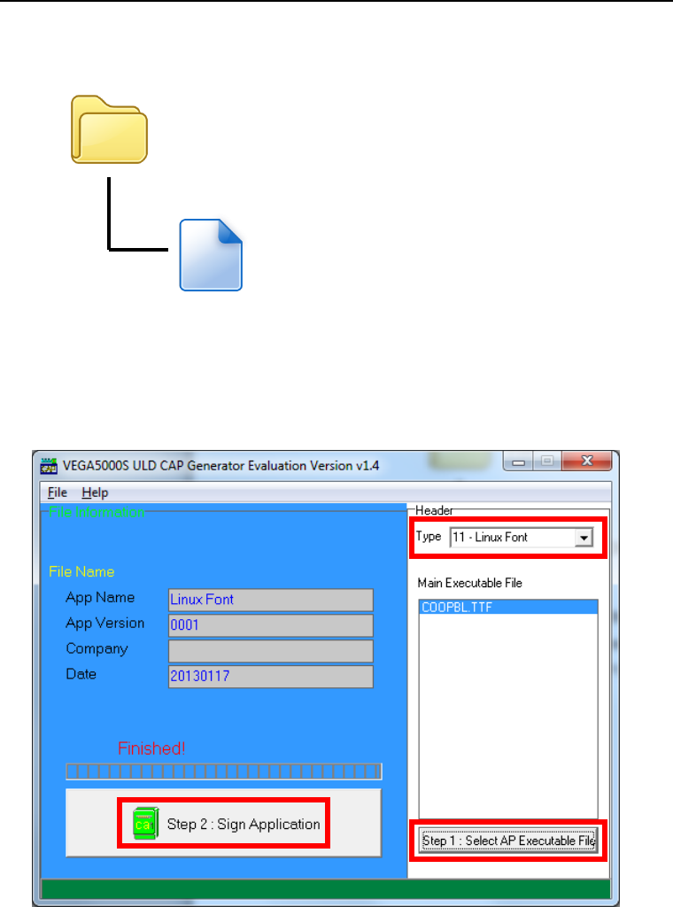
Copy the TTF file needed to a empty folder.
Use CAP Generator to conver the TTF file to CAP.
Set type to [11 – Linux Font], press [Step 1] button select the TTF file.
Then press [Step 2] to generate CAP file.
Download the font CAP file to terminal.
TTF
COOPBL.TTF
Castles Technology Co., Ltd. Confidential • All Right Reserved. Pg. 65
In terminal application, add following code to display message using the
newly added font.
CTOS_LCDTTFSelect("COOPBL.TTF", 0);
CTOS_LCDFontSelectMode(d_FONT_TTF_MODE);
CTOS_LCDTSelectFontSize(0x203C); // 32x60
CTOS_LCDTClearDisplay();
CTOS_LCDTPrintXY(1, 1, "Hello World");
Or print message using the newly added font.
CTOS_PrinterTTFSelect("COOPBL.TTF", 0);
CTOS_PrinterFontSelectMode(d_FONT_TTF_MODE);
CTOS_LanguagePrinterFontSize(0x203C, 0, 0); // 32x60
CTOS_PrinterPutString("Hello World");

Castles Technology Co., Ltd. Confidential • All Right Reserved. Pg. 66
6. Advance Features
6.1. VEGA5000S GNU Project Debugger (GDB)
Developers may use GDB to debug the programs directly on
VEGA5000Sterminal.
6.1.1. About GDB
GDB, the GNU Project debugger, allows you to see what is going on
`inside' another program while it executes -- or what another program
was doing at the moment it crashed.
GDB can do four main kinds of things (plus other things in support of
these) to help you catch bugs in the act:
Start your program, specifying anything that might affect its
behavior.
Make your program stop on specified conditions.
Examine what has happened, when your program has stopped.
Change things in your program, so you can experiment with
correcting the effects of one bug and go on to learn about
another.
For more detail, please refer to http://sources.redhat.com/gdb/.
Castles Technology Co., Ltd. Confidential • All Right Reserved. Pg. 67
6.1.2. SetupGDB
Access to GDB Setting Menu.
Press [4] button to enter System Settings menu.
Press [F3] button three times to GDB Setting Menu (page 4).
Change following settings:
Set GDB Mode to Y (enable)
Set GDB Timeout, the time that GDB server (on terminal) waits
for connection. Default is 60 seconds.
Set GDB Channel, the communication channel between GDB
server (on terminal) and SDK IDE on PC.
‘E’ indicates to use TCP/IP channel
‘U’ indicates USB mode
Set Ethernet IP & Port, terminal IP address and GDB server (on
terminal) port. Ifcoummincation channel is set to TCP/IP.
Press [] button to select setting.
Press [OK] button to change the setting value.
Press [] button to toggle Y N Y.
System Menu
1.Download AP
2.System Info
3.Memory Status
4.Sys Settings
5.Test Utility
6.Factory Reset
7.Power Off
SYS SETTINGS
GDB Mode : N
GDB Timeout : X
GDB Channel : X
ETHER IP/PORT
F2:Prev Page
SYS SETTINGS
GDB Mode : Y
GDB Timeout: 60s
GDB Channel : E
ETHER IP/PORT
192.168.0.71
5000
F2:Prev Page
Change to
SYS SETTINGS
GDB Mode : N
GDB Timeout : X
GDB Channel : X
ETHER IP/PORT
F2:Prev Page
Castles Technology Co., Ltd. Confidential • All Right Reserved. Pg. 68
6.1.3. Start Debugging
The GDB function is supported in the Castles SDK version 6.10 or
higher. Please ensure you have already installed this SDK into your
computer before using GDB.
Step 1: Run Castles CTOS Development Suite
Step 2: Open project to debug
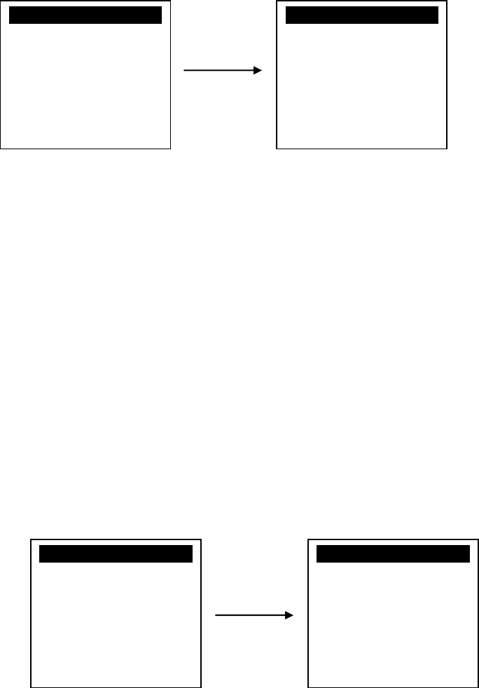
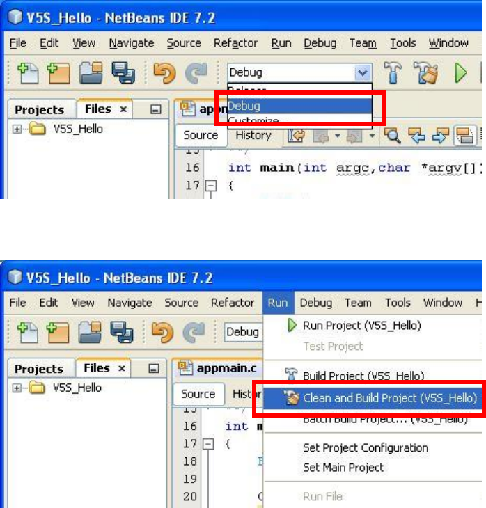
Step 3: Set project configuration to “Debug”
Step 4: Rebuild the project.
Castles Technology Co., Ltd. Confidential • All Right Reserved. Pg. 69
Step 5: Sign the application and load the CAP files to terminal.
Step 6: Execute the application.
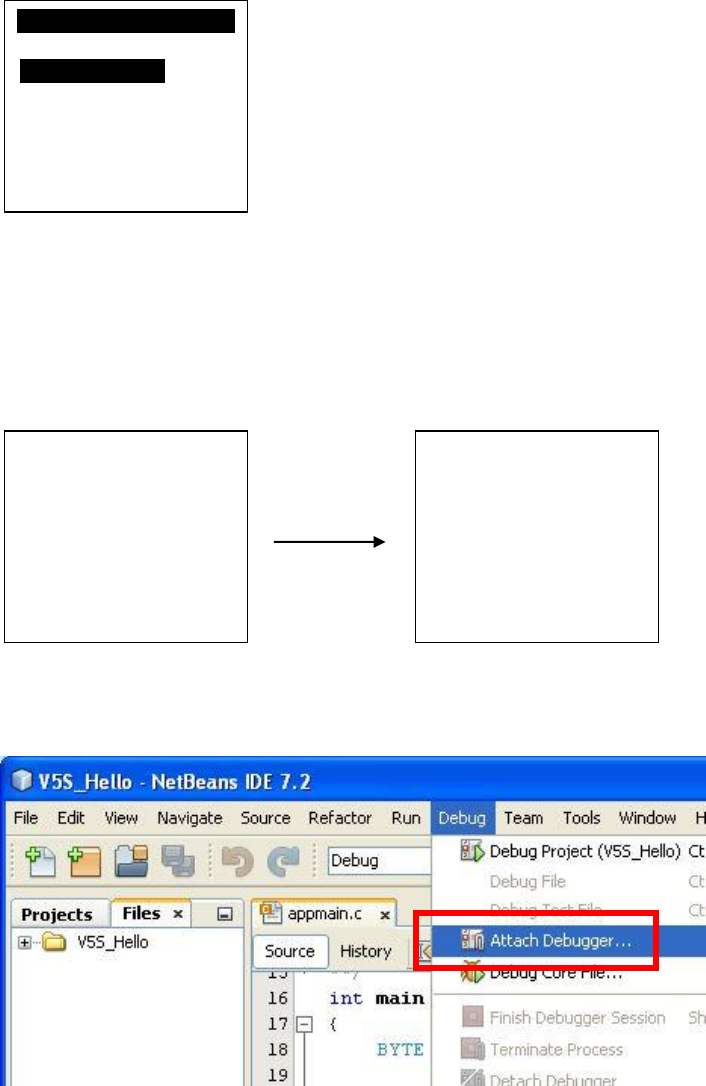
Step 7: Press [OK] button to confirm open debug mode. Terminal will
wait for connection from SDK IDE until timeout.
Step 7: In SDK IDE, from Debug menu select “Attach Debugger…”.
Program Manager
-----------01/02
1.V5S_Hello
F1:Download
Open Debug Mode
Confirm?
Y:OK N:X
Press OK
Local IP:
192.168.0.71
Listen Port:
5000
Listening… 59
Castles Technology Co., Ltd. Confidential • All Right Reserved. Pg. 70
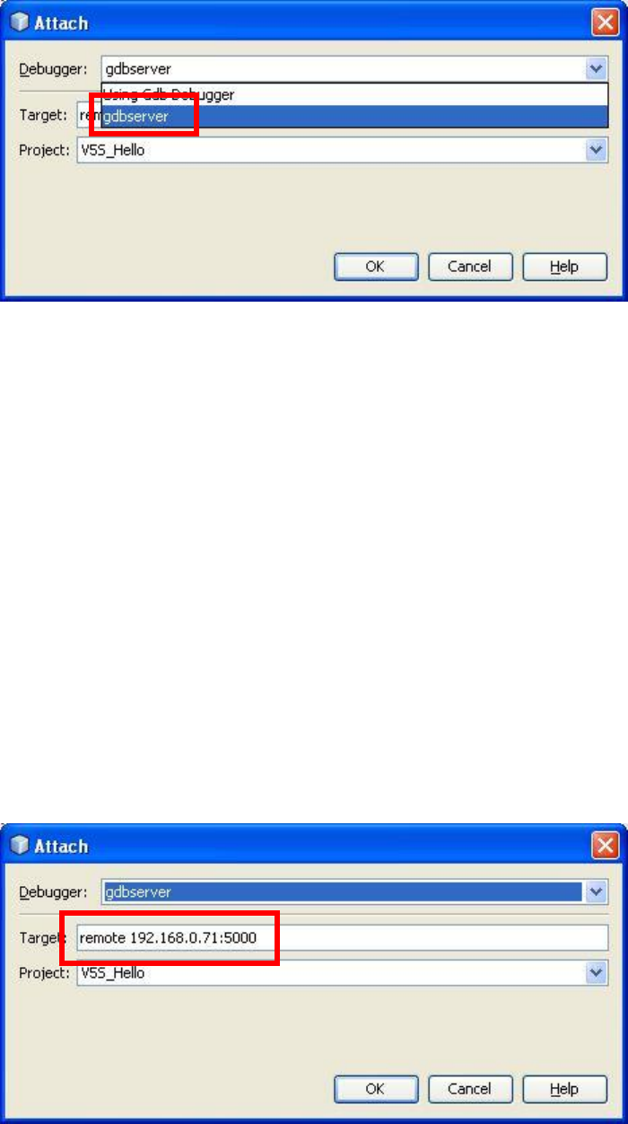
Step 8: Select debugger as “gdbserver”.
Step 8:
Ethernet Channel:
Please input the terminal IP address andGDB port in the format “remote
HostIP:HostPort” on the “Target” editor.Andselect your application from
the “Project” combobox. When finishing, press‘OK’ button to connect
with the terminal.
USB Channel:
If using USB channel to debug, input port number in the format
“remote/dev/ttySn” on the“Target” editor. ‘n’ indicates comport number
minus 1. Forexample, if the PC port that the terminal connects with is
COM3, pleaseinput“remote /dev/ttyS2” on the “Target” editor.Andselect
your application from the “Project” combobox. When finishing, press‘OK’
button to connect with the terminal.
Castles Technology Co., Ltd. Confidential • All Right Reserved. Pg. 71
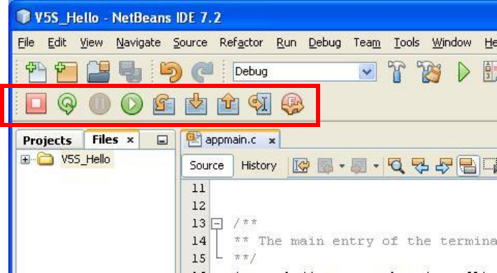
Step 9: Press OK. After successful connected to terminal, the debug
menu will beenable. User may use breakpoint or use “Step Over” for
tracing.
Castles Technology Co., Ltd. Confidential • All Right Reserved. Pg. 72
7. Operation Notes
7.1. Operation Notes
1. VEGA5000S mainly used both on table and hand-held.
2. When inserting or swiping the cards, there will be some distance between the terminal
and human body, rather than be appressed to the human body.
3. The VEGA5000S would not be put into the pocket or tie around the waist.
~ END ~

FCC Regulations
This device complies with part 15 of the FCC Rules. Operation is subject to the following two
conditions: (1) This device may not cause harmful interference, and (2) this device must accept any
interference received, including interference that may cause undesired operation.
Changes or modifications not expressly approved by the party responsible for compliance could void
the user‘s authority to operate the equipment.
*******************************************************************************************************************
*********
This equipment has been tested and found to comply with the limits for a Class B digital device,
pursuant to part 15 of the FCC Rules. These limits are designed to provide reasonable protection
against harmful interference in a residential installation. This equipment generates, uses and can
radiate radio frequency energy and, if not installed and used in accordance with the instructions, may
cause harmful interference to radio communications. However, there is no guarantee that interference
will not occur in a particular installation. If this equipment does cause harmful interference to radio or
television reception, which can be determined by turning the equipment off and on, the user is
encouraged to try to correct the interference by one or more of the following measures:
—Reorient or relocate the receiving antenna.
—Increase the separation between the equipment and receiver.
—Connect the equipment into an outlet on a circuit different from that to which the receiver is
connected.
—Consult the dealer or an experienced radio/TV technician for help.
*******************************************************************************************************************
*********
This device is designed and manufactured not to exceed the emission limits for exposure to radio
frequency (RF) energy set by the Federal Communications Commission of the U.S. Government.
This device should be installed and operated with minimum distance 10 mm between the radiator &
your body.