CCL ELECTRONICS 6068A1707 Professional Weather Station User Manual
CCL ELECTRONICS LTD Professional Weather Station
UserManual.wiki
>
CCL ELECTRONICS
>
6068A1707 User Manual
User Manual
Navigation menu
Upload a User Manual
Namespaces
Wiki Guide
HTML
PDF
Info
Views
User Manual
Discussion / Help
Navigation
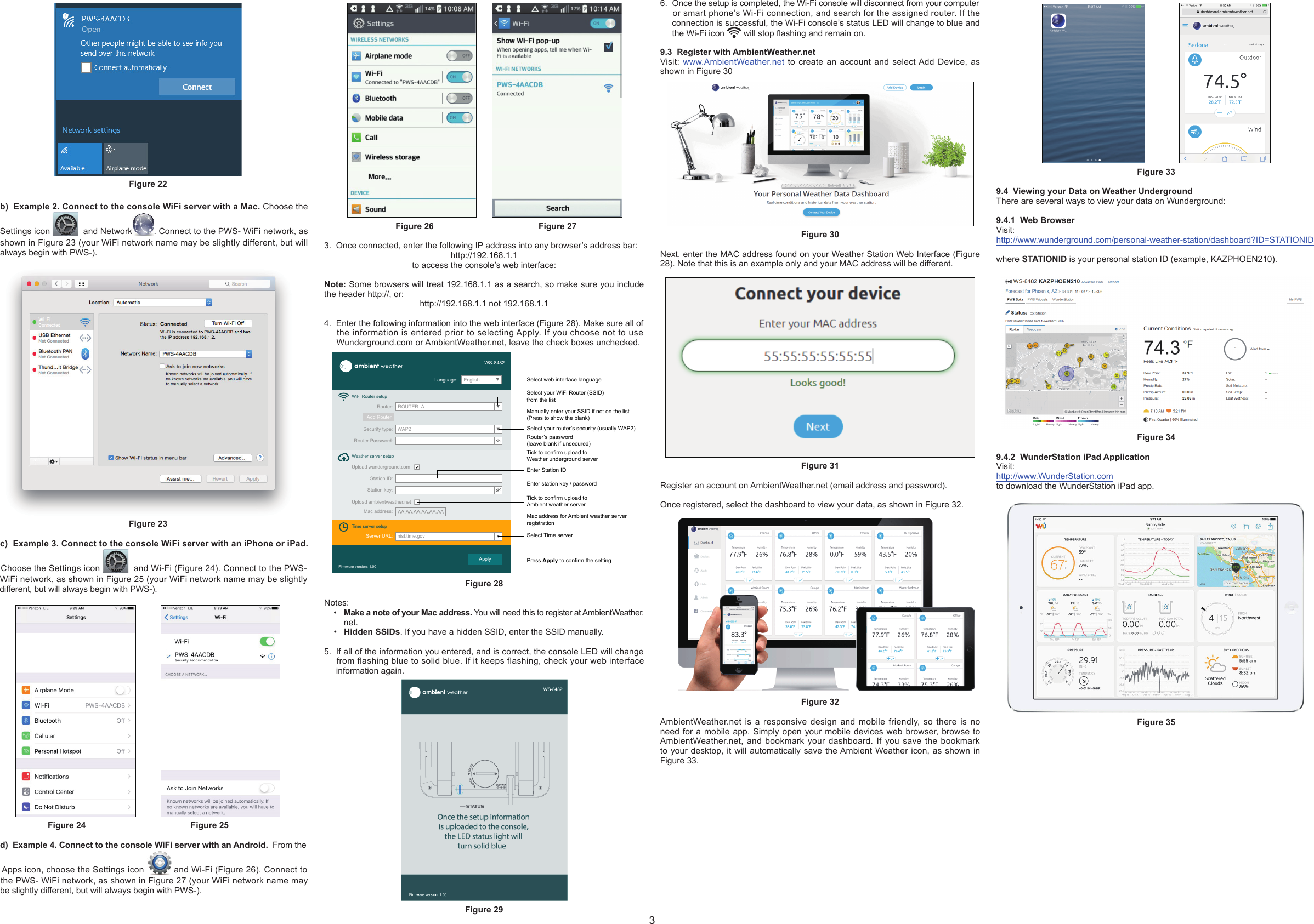
![Ambient Weather WS-8482 7-Channel Wireless InternetRemote Monitoring Weather Station with Indoor / Outdoor Temperature & Humidity User Manual1. IntroductionThank you for your purchase of the Ambient Weather WS-8482 7-Channel WirelessInternet Remote Monitoring Weather Station with Indoor / Outdoor Temperature &Humidity.The following user guide provides step by step instructions for installation, operation and troubleshooting. To download the latest full sized manual and additional troubleshooting tips, please visit:http://ambientweather.wikispaces.com/ws8482Figure 12. WarningsWarning. Only use the included approved AC adapter.3. Getting StartedNote: Remove the plastic lm from the console face before getting started.3.1 Parts ListQTY Item1Display ConsoleFrame Dimensions (L x W x H): 130 x 112 x 27.5mm (5.1 x 4.4 x 1.1 in)1Wireless Indoor/Outdoor Thermo-Hygrometer (L x W x H): 4.5 x 2.5 x 1.5”1 UL Rated Class 5 AC Adapter1 User Manual3.2 Product Features3.2.1 Display131327810111296415145161. [ ALARM / SNOOZE ] key2. LCD display3. [ CHANNEL / + ] key4. [ MODE / ALARM ] key5. [ MEM / - ] key6. Wall mount suspension eye7. [ TUNE ] key8. [ TIME SET ] key9. Backlight slide switch10. Battery compartment11. Status LED12. Power jack13. [ °C / °F ] key14. [REFRESH] key15. [ RESET ] key16. [SENSOR / WI-FI] key3.2.2 Wireless Indoor/Outdoor Thermo-Hygrometer Transmitter13254Figure 2No Description No Description1Transmitter LED (ashes when the remote is transmitting)4 [RESET] button2 Suspension eye for hanging 5 2 x AA battery compartment3 Transmitter channel (assign the transmitter to 1, 2 ,3 ,4, 5, 6, or 7 default = 1)Note: The WS-8482 supports seven wireless channels. If you have one sensor, leave the transmitter channel at Channel 1. If you have more than one sensor, set the appropriate channel, then power down and up the sensor (by removing and reinserting batteries).3.3 Powering Up3.3.1 Power Up Sequence Note: The power up sequence must be performed in the order shown in this section (remote transmitters FIRST, Display Console SECOND) to avoid sensor synchronization time out.The Indoor/Outdoor Wireless Transmitter(s):1. Remove the battery door on the sensor(s).2. If you have more than one sensor, make sure each sensor is on a different channel (reference Figure 2).3. Insert 2 x AA batteries into the battery compartment.4. Replace the battery door.The Console: Important Note: The power up sequence must be performed in this order (battery rst, AC adapter second) to prevent a low battery indication at power up.1. Place the wireless sensor(s) about 5 to 10 feet from the display console.2. Remove the battery door of the main console and insert the fresh CR2032 battery.3. Replace the battery door.4. Plug the AC adaptor into the DC jack of the console.5. After power up, all of LCD segments will be displayed. The console will enter access point (AP) mode, and the status LED on the back of the console will ash green.6. Do not touch any buttons until sensor synchronization is complete.Note: If no display is present after powering up the console, press the [RESET]button on the back of the console with an open ended paper clip or sharp tool.3.3.2 Initial Sensor SynchronizationThe console will automatically search for and connect to the sensors after it is powered up. You can also press [WI-FI / SENSOR] button to force the console to search for the sensors, and the console’s status LED will ash blue during the sensor(s) searching mode.Once the sensor connection is successful, the antenna mark and readings for temperature & humidity will appear on the display.3.4 Mount the SensorThe sensor can be free standing on a table, or mounted on a vertical wall with a nail ore screw. For best results, place between 10 and 100 feet of the display console.Figure 34. Console DisplayFigure 4 references the individual sections of the console display.Time & DateHumiditySectionTamperatureSectionFigure 45. Console LED Status LightThe console LED status light is on the back of the console. Reference Figure 5 forexplanation of the colored LED.Status LED LightAP Mode (WiFi access point mode) Flashing green LEDConnected to WiFi router Solid blue LEDWiFi search failed Flashing blue LEDFirmware updating Flashing red LEDManual sensor pairing modeby pressing the [SENSOR / WI-FI ] keyFlashing cyan LEDRefresh the upload data and sync internet time by pressing the [ Refresh ] keyFlashing purple LEDFigure 56. Battery and Memory BackupThe battery is intended for backup power only, and will not operate the display console.The following parameters are saved with back up battery if AC power is disconnected:• Date and Time• Max and Min Records• AlarmsThe following parameters are stored in memory when AC and battery power is disconnected:• Router settings• Weather server settings• Time server settings• Time zone offset• Sensor pairing7. Settings7.1 Time SettingsWhile in normal time mode, perform the following operations to set the time.Command Mode Settings Image[TIME SET] + 2 secondsEnter Time Zone SettingsPress [+] to increase, [-] to decrease. Refer-ence Figure 7. 00H → 01H...23H → -23H...-01H → 00H[TIME SET] Enter Daylight Savings Time OFF (AZ and HI) or ON (everywhere else).Press [+] or [-] to turn ON or OFF.[TIME SET] Hour Format Press [+] to toggle between 12 Hr and 24 Hr format.[TIME SET] Hour Press [+] to increase, [-] to decrease. [TIME SET] Minute Press [+] to increase, [-] to decrease.[TIME SET] Second Press [+] to reset to 0.[TIME SET] Year Press [+] to increase, [-] to decrease.[TIME SET] Month Day FormatPress [+] or [-] to switch between M-D (month-day) and D-M (day-month)[TIME SET] Month Press [+] to increase, [-] to decrease. [TIME SET] Day Press [+] to increase, [-] to decrease.[TIME SET] Enable or disable the internet time syncPress [+] or [-] to turn ON or OFF[TIME SET] Language Press [+] or [-] to change between EN (English), DE (German), FR (French), ES (Spanish) IT (Italian), NL (Dutch), and RU (Russian)EN DE FR ES IT NL RU [TIME SET] Exit Time Settings[TIME SET] + 2 seconds means press and hold the TIME SET button on the back of the display console for two seconds.[TIME SET] means press but do not hold the TIME SET button.Figure 67.1.1 Time Zone SettingsThe following table provides times zones throughout the world. Locations in the eastern hemisphere are positive, and locations in the western hemisphere are negative.Hours from GMTTime Zone Cities-12 IDLW: International Date Line West ----11 NT: Nome Nome, AK-10 AHST: Alaska-Hawaii StandardCAT: Central AlaskaHST: Hawaii StandardHonolulu, HI-9 YST: Yukon Standard Yukon Territory-8 PST: Pacic Standard Los Angeles, CA, USA-7 MST: Mountain Standard Denver, CO, USA-6 CST: Central Standard Chicago, IL, USA-5 EST: Eastern Standard New York, NY, USA-4 AST: Atlantic Standard Caracas-3 --- São Paulo, Brazil-2 AT: Azores Azores, Cape Verde Islands-1 WAT: West Africa ---0 GMT: Greenwich MeanWET: Western EuropeanLondon, England1 CET: Central European Paris, France2 EET: Eastern European Athens, Greece3 BT: Baghdad Moscow, Russia4 --- Abu Dhabi, UAE5 --- Tashkent6 --- Astana7 --- Bangkok8 CCT: China Coast Bejing9 JST: Japan Standard Tokyo10 GST: Guam Standard Sydney11 --- Magadan12 IDLE: International Date Line EastNZST: New Zealand StandardWellington, New ZealandFigure 77.2 Sensor Pairing with the Display ConsoleThe console will automatically search and connect to your wireless sensor(s). You can also press the [Wi-Fi / SENSOR] key to search for your sensor(s) manually. Once your sensor(s) pair up successfully, the sensor(s) signal strength indication and sensor information will appear on your display console.Note: The status LED will ash cyan after you press the [Wi-Fi / SENSOR] key to search the sensor(s) manually.7.3 WiFi Connection StatusWhen the console successfully connects to your Wi-Fi router, the Wi-Fi signal icon will appear on the LCD display, next to the time. If the Wi-Fi signal is not stable or the console is trying to connect to the router, the icon will ash. If the icon disappears, it means the console is not connected to the Wi-Fi router.7.4 Time Server Sync StatusAfter the console has connected to the internet, it will attempt to connect to the internet time server to obtain the time. Once the connection succeeds and the console’s time has updated, the SYNC icon will appear on the LCD. The time will automatically synchronize to the internet twice per day (noon and midnight).Also you can press the [REFRESH] key to obtain the internet time manually.7.5 Daylight Savings Time AdjustmentThe clock will automatically adjust to Daylight Savings Time, unless turned off in the Time Settings.1](https://usermanual.wiki/CCL-ELECTRONICS/6068A1707/User-Guide-3914043-Page-1.png)
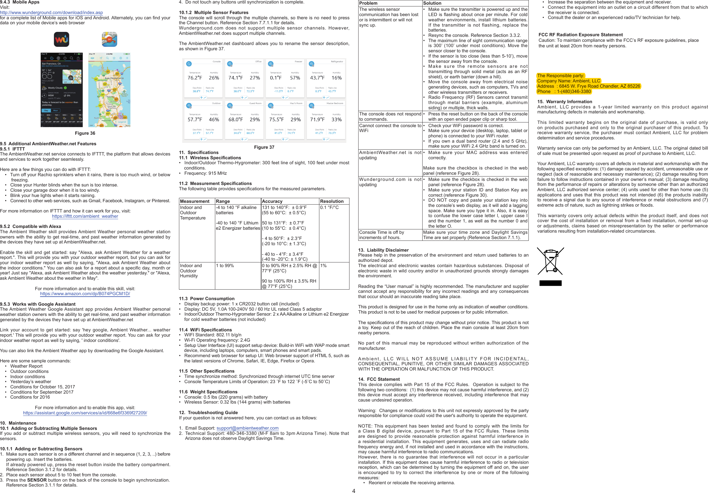
![7.6 Alarm Settings7.6.1 Setting the Alarm TimeWhile in normal time mode, perform the following operations to set the alarm time.Command Mode Settings[MODE/ALARM] + 2 secondsEnter Alarm SettingsAlarm Hour Press [+] to increase, [-] to decrease.[MODE/ALARM] Alarm Minute Press [+] to increase, [-] to decrease.[MODE/ALARM] Exit Alarm Settings [MODE/ALARM] + 2 seconds means press and hold the ALARM button on the side of the display for two seconds.[MODE/ALARM] means press but do not hold the ALARM button on the side of the display.Note: Setting the alarm time will automatically turn the alarm on.Figure 87.6.2 Turning On and Off the Alarm Feature1. While in normal time mode, press the MODE/ALARM button to display the alarmtime set in Section 7.6.1.2. Press the MODE/ALARM button again to turn on and off the alarm. The time alarmicon will be present when the alarm is set, and will disappear when the timealarm is off.3. When the alarm time is reached, the alarm will sound.7.6.3 Using the Alarm and Snooze FunctionsWhen the alarm sounds, press and hold the ALARM / SNOOZE button (on the top of the console) for two seconds to turn off the alarm sound. The alarm bell will stop ashing. The alarm will sound again in 24 hours.If no button is pressed during the alarm period, the alarm will turn off automatically after two minutes.To temporarily silence the alarm, press the ALARM / SNOOZE button on the top of the console. The alarm bell icon will keep ashing.If the snooze function is turned on, the 4-step crescendo alarm will sound every 5 minutes. Press and hold the ALARM / SNOOZE button for two seconds to turn off the alarm sound. The alarm bell will stop ashing.7.7 Temperature and Humidity Display and Settings7.7.1 Temperature Units of MeasurePress the °F / °C button on the back of the display to change the temperature units of measure.7.7.1.1 Changing Sensor Channel NumbersThe console supports up to seven wireless indoor/outdoor sensors. If you have two or more sensors, press the CHANNEL + button to switch to different channels.Press and hold the CHANNEL + button for two seconds to automatically scroll between the sensor channels every four seconds. The scroll icon will appear, as shown in Figure 9. To stop the automatic scrolling, press the CHANNEL + button again.Indoor Channel 1 Channel 6Figure 97.7.1.2 Indoor Comfort IconThe comfort indication is a pictorial indication calculated from the indoor air temperature and humidity. Each indoor channel displays a comfort icon.The comfort indication can vary at the same temperature, depending on the humidity. There is no comfort Indication when the temperature is below 0°C (32°F) or over 60°C (140°F).To hide or unhide the comfort icon, press and hold the [CHANNEL / +] and [MEM / -] keys at the same time for 2 seconds.Too cold Comfortable Too hotFigure 107.7.2 Temperature and Humidity TrendThe temperature trend arrow indicator displays the current rate of change of the indoor and outdoor temperature and humidity.Arrow indicatortrend Rising Steady FallingFigure 117.7.3 Temperature and Humidity Measurements LimitsWhen temperature is below -40 °C, (-40 °F), the LCD will display “Lo”. If temperature is above 80 °C (176 °F), LCD will display “HI”.When humidity is below 1%, the LCD will display “Lo”. If humidity is above 99%, the LCD will display “HI”.This can also indicate there is a problem with the temperature and humidity sensor.7.8 Max / Min Temperature and Humidity RecordThe console can display the daily or all time (since the last reset) MAX/MIN temperature and humidity records.1. In normal mode, press the MEM / - key to switch between the daily (D) andall time (S) (since last reset) MAX/MIN temperature and humidity values on theright side section of LCD display, as shown in Figure 12.2. When the MAX/MIN records are shown, the display will return to normalmode after 5 seconds.Daily MAX / MIN Since MAX / MINFigure 123. Press and hold the MEM/- button for two seconds to clear the all-time Max/Minrecords. The display will update as shown in Figure 13.Figure 137.9 CalibrationTo calibrate the temperature and humidity:1. In the normal time mode, Press the TUNE key on the back of the console toenter the calibration mode.2. Press CHANNEL / + or MEM / - key to select the channel.Figure 143. Press the MODE / ALARM key to switch between temperature and humidity.The parameter will ash when selected.4. In the temperature calibration mode, press the CHANNEL /+ or MEM/- keyto increase or decrease the calibrated temperature offset in 0.1º increments.Press and hold the CHANNEL /+ or MEM/- key to change rapidly, where:Calibrated Temperature = Measured Temperature + Temperature Offset5. In the humidity calibration mode, press the CHANNEL /+ or MEM/- keyto increase or decrease the calibrated humidity offset in 1% increments. Pressand hold the CHANNEL /+ or MEM/- key to change rapidly, where:Calibrated Humidity = Measured Humidity + Humidity OffsetTemperature Calibration Humidity CalibrationFigure 156. Press the TUNE key again to exit the calibration mode.Notes:• The comfort icon is based on calibrated temperature and humidity values.• To clear the calibration for a specic channel and parameter, press and hold MODE/ALARM key for 2 seconds during the temperature or humidity calibration mode.7.9.1 Calibration DiscussionThe purpose of calibration is to ne tune or correct for any sensor error associated with the devices margin of error. Errors can occur due to electronic variation (example, the temperature sensor is a resistive thermal device or RTD, the humidity sensor is a capacitance device), or degradation (contamination of sensors).Calibration is only useful if you have a known calibrated source you can compare it against, and is optional. This section discusses practices, procedures and sources for sensor calibration to reduce manufacturing and degradation errors. Do not compare your readings obtained from sources such as the internet, radio, television or newspapers. The purpose of your weather station is to measure conditions of your surroundings, which vary signicantly from location to location.Parameter Type of CalibrationDefault Typical Calibration SourceTemperature Offset Current Value Red Spirit or Mercury Thermometer (1)Humidity Offset Current Value Sling Psychrometer (2)Figure 16(1) Temperature errors can occur when a sensor is placed too close to a heat source(such as a building structure, the ground or trees).To calibrate temperature, we recommend a mercury or red spirit (uid) thermometer. Bi-metal (dial) and digital thermometers (from other weather stations) are not agood source and have their own margin of error. Using a local weather station inyour area is also a poor source due to changes in location, timing (airport weatherstations are only updated once per hour).Place the sensor in a shaded, controlled environment next to the uid thermometer,and allow the sensor to stabilize for 48 hours. Compare this temperature to theuid thermometer and adjust the console to match the uid thermometer.(2) Humidity is a difcult parameter to measure electronically and drifts over time dueto contamination. In addition, location has an adverse effect on humidity readings(installation over dirt vs. lawn for example).Ofcial stations recalibrate or replace humidity sensors on a yearly basis. Due tomanufacturing tolerances, the humidity is accurate to ± 5%. To improve thisaccuracy, the indoor and outdoor humidity can be calibrated using an accuratesource, such as a sling psychrometer.8. Additional Console Features8.1 Wireless Signal Strength and Signal Loss1. The signal strength is displayed for each wireless channels as follows:The icon blinks every time the signal is received, or once per minute.Strong wireless signalFair wireless signalWeak wireless signalFigure 172. If the signal for a specic channel has discontinued and does not recover within 15 minutes, the temperature and humidity will display “Er” for the correspondingchannel, as shown in Figure 18.3. If the signal does not recover within 48 hours, the “Er” display will be constantlydisplayed. You need to replace the batteries in the sensor and then press SENSOR /WI-FI key to pair up with the sensor again, as described in Section 7.2.Figure 188.2 Low Battery IndicationIf the console or sensor battery is low, the low battery icon will display. The icon will only appear when the corresponding channel is displayed. For example, if the Channel 2 sensor battery is low, the low battery icon is displayed when Channel 2 is displayed.Indoor low battery icon Channel 2 low battery iconFigure 198.3 Low Temperature IconWhen the temperature is less than 3 ºC (37.4 ºF), the LO temperature icon will be displayed. The purpose of this icon is ice can begin forming at this temperature. Figure 208.4 Remove Sensor from ConsoleTo de-link a sensor from the console unit, press the CHANNEL / + key or MEM / - key to the desired channel, then press and hold the ºC/ºF key for 2 seconds.9. WiFi Connection and Weather Servers9.1 Register at Wunderground.com (Weather Underground)Note: The Weather Underground website is subject to change.1. Visit Wunderground.com, and select the Join link in the upper right and cornerand create a Free Account.2. From the menu, Select More | Add a Weather Station, or visit:https://www.wunderground.com/personal-weather-station/signup3. Click Send Validation Email. Respond to the validation email from Wunderground(it may take a several minutes).4. Revisit More | Add a Weather Station, or visit:https://www.wunderground.com/personal-weather-station/signupagain and enter all of the information requested.5. Once registered, you receive a station ID and password. Make a note of this.You will need to enter it into your weather station web interface shown inFigure 28 (Figure 21 is an example and your station ID and password will bedifferent.Figure 21Note: Your station ID will have the form: KSSCCCC###, where K is for USA station (I for international), SS is your state, CCCC is your city and ### is the station number in that city.In the example above, KAZPHOEN424 is in the USA (K), State of Arizona (AZ), City of Phoenix (PHOEN) and #424.9.2 WiFi Setup1. When you first power up the console, or press and hold the WI-FI / SENSOR button for six seconds in normal mode, the console green LED will flash tosignify that it has entered WAP (wireless access point) mode, and is ready to enterfor WIFI settings.2. Use your smart phone, tablet, or computer to connect to the console through WiFi.Note that when the console programming is complete, you will resume your defaultWiFi connection. Note that you cannot connect two devices at the same timewhen programming.a) Example 1: Connect to the console WiFi server with a PC. Choose WiFinetwork settings from Windows (or search “Change Wi-Fi Settings” from Windows),and Connect to the PWS- WiFi network, as shown in Figure 22 (your WiFi network name may be slightly different, but will always begin with PWS-).2](https://usermanual.wiki/CCL-ELECTRONICS/6068A1707/User-Guide-3914043-Page-2.png)