CCL ELECTRONICS 6068A1707 Professional Weather Station User Manual
CCL ELECTRONICS LTD Professional Weather Station
User Manual
Ambient Weather WS-8482 7-Channel Wireless Internet
Remote Monitoring Weather Station with Indoor / Outdoor
Temperature & Humidity User Manual
1. Introduction
Thank you for your purchase of the Ambient Weather WS-8482 7-Channel Wireless
Internet Remote Monitoring Weather Station with Indoor / Outdoor Temperature &
Humidity.
The following user guide provides step by step instructions for installation, operation
and troubleshooting. To download the latest full sized manual and additional
troubleshooting tips, please visit:
http://ambientweather.wikispaces.com/ws8482
Figure 1
2. Warnings
Warning. Only use the included approved AC adapter.
3. Getting Started
Note: Remove the plastic lm from the console face before getting started.
3.1 Parts List
QTY Item
1Display Console
Frame Dimensions (L x W x H): 130 x 112 x 27.5mm (5.1 x 4.4 x 1.1 in)
1Wireless Indoor/Outdoor Thermo-Hygrometer (L x W x H): 4.5 x 2.5 x 1.5”
1 UL Rated Class 5 AC Adapter
1 User Manual
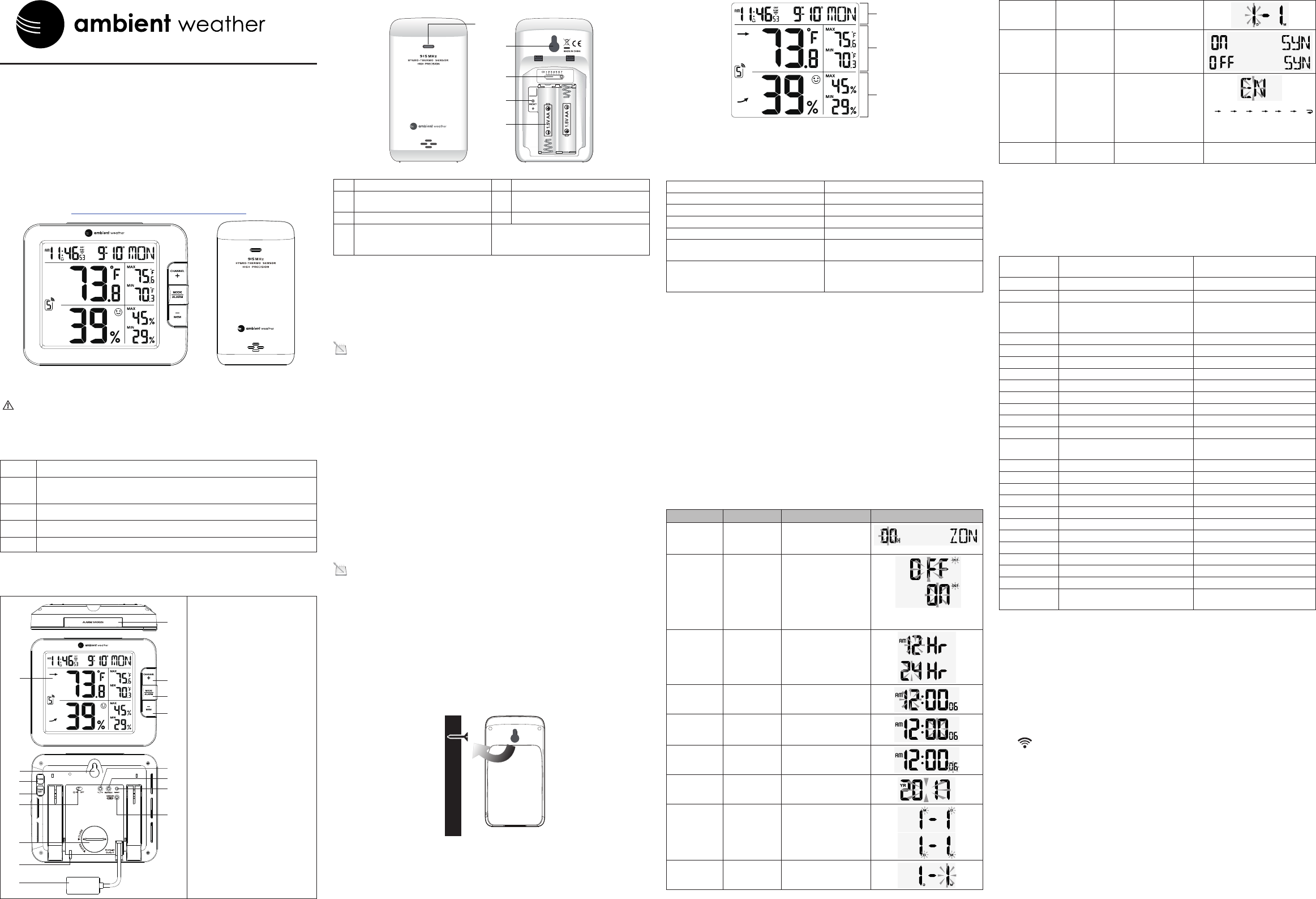
3.2 Product Features
3.2.1 Display
1
3
13
2
7
8
10
11
12
9
6
4
15
14
5
16
1. [ ALARM / SNOOZE ] key
2. LCD display
3. [ CHANNEL / + ] key
4. [ MODE / ALARM ] key
5. [ MEM / - ] key
6. Wall mount suspension eye
7. [ TUNE ] key
8. [ TIME SET ] key
9. Backlight slide switch
10. Battery compartment
11. Status LED
12. Power jack
13. [ °C / °F ] key
14. [REFRESH] key
15. [ RESET ] key
16. [SENSOR / WI-FI] key
3.2.2 Wireless Indoor/Outdoor Thermo-Hygrometer Transmitter
1
3
2
5
4
Figure 2
No Description No Description
1Transmitter LED (ashes when the
remote is transmitting)
4 [RESET] button
2 Suspension eye for hanging 5 2 x AA battery compartment
3 Transmitter channel (assign the
transmitter to 1, 2 ,3 ,4, 5, 6, or 7
default = 1)
Note: The WS-8482 supports seven wireless channels. If you have one sensor,
leave the transmitter channel at Channel 1. If you have more than one sensor, set
the appropriate channel, then power down and up the sensor (by removing and
reinserting batteries).
3.3 Powering Up
3.3.1 Power Up Sequence
Note: The power up sequence must be performed in the order shown in this
section (remote transmitters FIRST, Display Console SECOND) to avoid sensor
synchronization time out.
The Indoor/Outdoor Wireless Transmitter(s):
1. Remove the battery door on the sensor(s).
2. If you have more than one sensor, make sure each sensor is on a different
channel (reference Figure 2).
3. Insert 2 x AA batteries into the battery compartment.
4. Replace the battery door.
The Console:
Important Note: The power up sequence must be performed in this order
(battery rst, AC adapter second) to prevent a low battery indication at power up.
1. Place the wireless sensor(s) about 5 to 10 feet from the display console.
2. Remove the battery door of the main console and insert the fresh CR2032 battery.
3. Replace the battery door.
4. Plug the AC adaptor into the DC jack of the console.
5. After power up, all of LCD segments will be displayed. The console will enter access
point (AP) mode, and the status LED on the back of the console will ash green.
6. Do not touch any buttons until sensor synchronization is complete.
Note: If no display is present after powering up the console, press the [RESET]
button on the back of the console with an open ended paper clip or sharp tool.
3.3.2 Initial Sensor Synchronization
The console will automatically search for and connect to the sensors after it is
powered up. You can also press [WI-FI / SENSOR] button to force the console
to search for the sensors, and the console’s status LED will ash blue during the
sensor(s) searching mode.
Once the sensor connection is successful, the antenna mark and readings for
temperature & humidity will appear on the display.
3.4 Mount the Sensor
The sensor can be free standing on a table, or mounted on a vertical wall with a nail
ore screw. For best results, place between 10 and 100 feet of the display console.
Figure 3
4. Console Display
Figure 4 references the individual sections of the console display.
Time & Date
Humidity
Section
Tamperature
Section
Figure 4
5. Console LED Status Light
The console LED status light is on the back of the console. Reference Figure 5 for
explanation of the colored LED.
Status LED Light
AP Mode (WiFi access point mode) Flashing green LED
Connected to WiFi router Solid blue LED
WiFi search failed Flashing blue LED
Firmware updating Flashing red LED
Manual sensor pairing mode
by pressing the [SENSOR / WI-FI ] key
Flashing cyan LED
Refresh the upload data and sync internet
time
by pressing the [ Refresh ] key
Flashing purple LED
Figure 5
6. Battery and Memory Backup
The battery is intended for backup power only, and will not operate the display console.
The following parameters are saved with back up battery if AC power is
disconnected:
• Date and Time
• Max and Min Records
• Alarms
The following parameters are stored in memory when AC and battery power is
disconnected:
• Router settings
• Weather server settings
• Time server settings
• Time zone offset
• Sensor pairing
7. Settings
7.1 Time Settings
While in normal time mode, perform the following operations to set the time.
Command Mode Settings Image
[TIME SET] +
2 seconds
Enter Time
Zone Settings
Press [+] to increase,
[-] to decrease. Refer-
ence Figure 7. 00H → 01H...23H → -23H...-01H → 00H
[TIME SET] Enter Daylight
Savings Time
OFF (AZ and
HI) or ON
(everywhere
else).
Press [+] or [-] to turn
ON or OFF.
[TIME SET] Hour Format Press [+] to toggle
between 12 Hr and 24
Hr format.
[TIME SET] Hour Press [+] to increase, [-]
to decrease.
[TIME SET] Minute Press [+] to increase, [-]
to decrease.
[TIME SET] Second Press [+] to reset to 0.
[TIME SET] Year Press [+] to increase, [-]
to decrease.
[TIME SET] Month Day
Format
Press [+] or [-] to switch
between M-D (month-
day) and D-M (day-
month)
[TIME SET] Month Press [+] to increase, [-]
to decrease.
[TIME SET] Day Press [+] to increase, [-]
to decrease.
[TIME SET] Enable or
disable the
internet time
sync
Press [+] or [-] to turn
ON or OFF
[TIME SET] Language Press [+] or [-] to
change between
EN (English), DE
(German), FR
(French), ES (Spanish)
IT (Italian), NL (Dutch),
and RU (Russian)
EN
DE
FR
ES
IT
NL
RU
[TIME SET] Exit Time
Settings
[TIME SET] + 2 seconds means press and hold the TIME SET button on the back of
the display console for two seconds.
[TIME SET] means press but do not hold the TIME SET button.
Figure 6
7.1.1 Time Zone Settings
The following table provides times zones throughout the world. Locations in the
eastern hemisphere are positive, and locations in the western hemisphere are negative.
Hours from
GMT
Time Zone Cities
-12 IDLW: International Date Line West ---
-11 NT: Nome Nome, AK
-10 AHST: Alaska-Hawaii Standard
CAT: Central Alaska
HST: Hawaii Standard
Honolulu, HI
-9 YST: Yukon Standard Yukon Territory
-8 PST: Pacic Standard Los Angeles, CA, USA
-7 MST: Mountain Standard Denver, CO, USA
-6 CST: Central Standard Chicago, IL, USA
-5 EST: Eastern Standard New York, NY, USA
-4 AST: Atlantic Standard Caracas
-3 --- São Paulo, Brazil
-2 AT: Azores Azores, Cape Verde Islands
-1 WAT: West Africa ---
0 GMT: Greenwich Mean
WET: Western European
London, England
1 CET: Central European Paris, France
2 EET: Eastern European Athens, Greece
3 BT: Baghdad Moscow, Russia
4 --- Abu Dhabi, UAE
5 --- Tashkent
6 --- Astana
7 --- Bangkok
8 CCT: China Coast Bejing
9 JST: Japan Standard Tokyo
10 GST: Guam Standard Sydney
11 --- Magadan
12 IDLE: International Date Line East
NZST: New Zealand Standard
Wellington, New Zealand
Figure 7
7.2 Sensor Pairing with the Display Console
The console will automatically search and connect to your wireless sensor(s). You
can also press the [Wi-Fi / SENSOR] key to search for your sensor(s) manually.
Once your sensor(s) pair up successfully, the sensor(s) signal strength indication
and sensor information will appear on your display console.
Note: The status LED will ash cyan after you press the [Wi-Fi / SENSOR] key to
search the sensor(s) manually.
7.3 WiFi Connection Status
When the console successfully connects to your Wi-Fi router, the Wi-Fi signal
icon will appear on the LCD display, next to the time. If the Wi-Fi signal is not
stable or the console is trying to connect to the router, the icon will ash. If the icon
disappears, it means the console is not connected to the Wi-Fi router.
7.4 Time Server Sync Status
After the console has connected to the internet, it will attempt to connect to the
internet time server to obtain the time. Once the connection succeeds and the
console’s time has updated, the SYNC icon will appear on the LCD. The time will
automatically synchronize to the internet twice per day (noon and midnight).
Also you can press the [REFRESH] key to obtain the internet time manually.
7.5 Daylight Savings Time Adjustment
The clock will automatically adjust to Daylight Savings Time, unless turned off in the
Time Settings.
1
7.6 Alarm Settings
7.6.1 Setting the Alarm Time
While in normal time mode, perform the following operations to set the alarm time.
Command Mode Settings
[MODE/ALARM] + 2
seconds
Enter Alarm Settings
Alarm Hour
Press [+] to increase, [-] to decrease.
[MODE/ALARM] Alarm Minute Press [+] to increase, [-] to decrease.
[MODE/ALARM] Exit Alarm Settings
[MODE/ALARM] + 2 seconds means press and hold the ALARM button on the side
of the display for two seconds.
[MODE/ALARM] means press but do not hold the ALARM button on the side of the
display.
Note: Setting the alarm time will automatically turn the alarm on.
Figure 8
7.6.2 Turning On and Off the Alarm Feature
1. While in normal time mode, press the MODE/ALARM button to display the alarm
time set in Section 7.6.1.
2. Press the MODE/ALARM button again to turn on and off the alarm. The time alarm
icon will be present when the alarm is set, and will disappear when the time
alarm is off.
3. When the alarm time is reached, the alarm will sound.
7.6.3 Using the Alarm and Snooze Functions
When the alarm sounds, press and hold the ALARM / SNOOZE button (on the top
of the console) for two seconds to turn off the alarm sound. The alarm bell will stop
ashing. The alarm will sound again in 24 hours.
If no button is pressed during the alarm period, the alarm will turn off automatically
after two minutes.
To temporarily silence the alarm, press the ALARM / SNOOZE button on the top of
the console. The alarm bell icon will keep ashing.
If the snooze function is turned on, the 4-step crescendo alarm will sound every 5
minutes. Press and hold the ALARM / SNOOZE button for two seconds to turn off the
alarm sound. The alarm bell will stop ashing.
7.7 Temperature and Humidity Display and Settings
7.7.1 Temperature Units of Measure
Press the °F / °C button on the back of the display to change the temperature units
of measure.
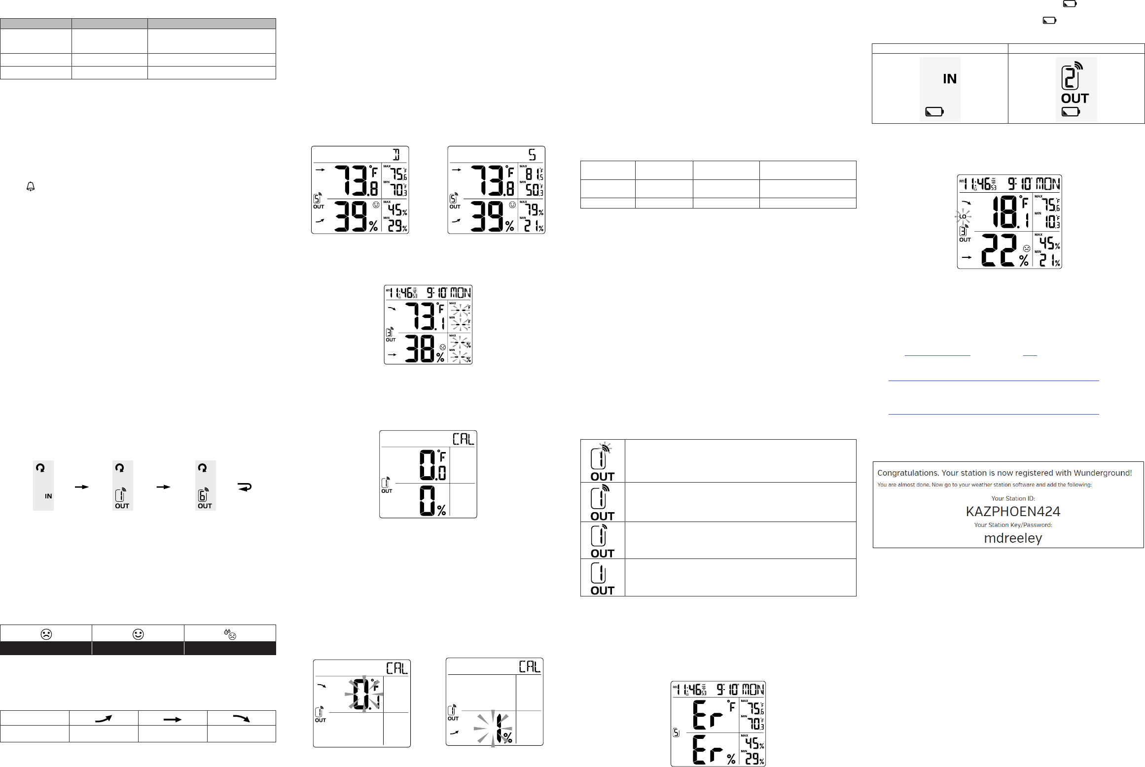
7.7.1.1 Changing Sensor Channel Numbers
The console supports up to seven wireless indoor/outdoor sensors. If you have two
or more sensors, press the CHANNEL + button to switch to different channels.
Press and hold the CHANNEL + button for two seconds to automatically scroll
between the sensor channels every four seconds. The scroll icon will appear, as
shown in Figure 9. To stop the automatic scrolling, press the CHANNEL + button again.
Indoor Channel 1 Channel 6
Figure 9
7.7.1.2 Indoor Comfort Icon
The comfort indication is a pictorial indication calculated from the indoor air
temperature and humidity. Each indoor channel displays a comfort icon.
The comfort indication can vary at the same temperature, depending on the
humidity. There is no comfort Indication when the temperature is below 0°C (32°F)
or over 60°C (140°F).
To hide or unhide the comfort icon, press and hold the [CHANNEL / +] and [MEM / -]
keys at the same time for 2 seconds.
Too cold Comfortable Too hot
Figure 10
7.7.2 Temperature and Humidity Trend
The temperature trend arrow indicator displays the current rate of change of the
indoor and outdoor temperature and humidity.
Arrow indicator
trend Rising Steady Falling
Figure 11
7.7.3 Temperature and Humidity Measurements Limits
When temperature is below -40 °C, (-40 °F), the LCD will display “Lo”. If temperature is
above 80 °C (176 °F), LCD will display “HI”.
When humidity is below 1%, the LCD will display “Lo”. If humidity is above 99%, the
LCD will display “HI”.
This can also indicate there is a problem with the temperature and humidity sensor.
7.8 Max / Min Temperature and Humidity Record
The console can display the daily or all time (since the last reset) MAX/MIN temperature
and humidity records.
1. In normal mode, press the MEM / - key to switch between the daily (D) and
all time (S) (since last reset) MAX/MIN temperature and humidity values on the
right side section of LCD display, as shown in Figure 12.
2. When the MAX/MIN records are shown, the display will return to normal
mode after 5 seconds.
Daily MAX / MIN Since MAX / MIN
Figure 12
3. Press and hold the MEM/- button for two seconds to clear the all-time Max/Min
records. The display will update as shown in Figure 13.
Figure 13
7.9 Calibration
To calibrate the temperature and humidity:
1. In the normal time mode, Press the TUNE key on the back of the console to
enter the calibration mode.
2. Press CHANNEL / + or MEM / - key to select the channel.
Figure 14
3. Press the MODE / ALARM key to switch between temperature and humidity.
The parameter will ash when selected.
4. In the temperature calibration mode, press the CHANNEL /+ or MEM/- key
to increase or decrease the calibrated temperature offset in 0.1º increments.
Press and hold the CHANNEL /+ or MEM/- key to change rapidly, where:
Calibrated Temperature = Measured Temperature + Temperature Offset
5. In the humidity calibration mode, press the CHANNEL /+ or MEM/- key
to increase or decrease the calibrated humidity offset in 1% increments. Press
and hold the CHANNEL /+ or MEM/- key to change rapidly, where:
Calibrated Humidity = Measured Humidity + Humidity Offset
Temperature Calibration Humidity Calibration
Figure 15
6. Press the TUNE key again to exit the calibration mode.
Notes:
• The comfort icon is based on calibrated temperature and humidity values.
• To clear the calibration for a specic channel and parameter, press and hold MODE/
ALARM key for 2 seconds during the temperature or humidity calibration mode.
7.9.1 Calibration Discussion
The purpose of calibration is to ne tune or correct for any sensor error associated
with the devices margin of error. Errors can occur due to electronic variation
(example, the temperature sensor is a resistive thermal device or RTD, the humidity
sensor is a capacitance device), or degradation (contamination of sensors).
Calibration is only useful if you have a known calibrated source you can compare it
against, and is optional. This section discusses practices, procedures and sources
for sensor calibration to reduce manufacturing and degradation errors. Do not
compare your readings obtained from sources such as the internet, radio, television
or newspapers. The purpose of your weather station is to measure conditions of
your surroundings, which vary signicantly from location to location.
Parameter Type of
Calibration
Default Typical Calibration Source
Temperature Offset Current Value Red Spirit or Mercury
Thermometer (1)
Humidity Offset Current Value Sling Psychrometer (2)
Figure 16
(1) Temperature errors can occur when a sensor is placed too close to a heat source
(such as a building structure, the ground or trees).
To calibrate temperature, we recommend a mercury or red spirit (uid) thermometer.
Bi-metal (dial) and digital thermometers (from other weather stations) are not a
good source and have their own margin of error. Using a local weather station in
your area is also a poor source due to changes in location, timing (airport weather
stations are only updated once per hour).
Place the sensor in a shaded, controlled environment next to the uid thermometer,
and allow the sensor to stabilize for 48 hours. Compare this temperature to the
uid thermometer and adjust the console to match the uid thermometer.
(2) Humidity is a difcult parameter to measure electronically and drifts over time due
to contamination. In addition, location has an adverse effect on humidity readings
(installation over dirt vs. lawn for example).
Ofcial stations recalibrate or replace humidity sensors on a yearly basis. Due to
manufacturing tolerances, the humidity is accurate to ± 5%. To improve this
accuracy, the indoor and outdoor humidity can be calibrated using an accurate
source, such as a sling psychrometer.
8. Additional Console Features
8.1 Wireless Signal Strength and Signal Loss
1. The signal strength is displayed for each wireless channels as follows:
The icon blinks every time the signal is received, or once per
minute.
Strong wireless signal
Fair wireless signal
Weak wireless signal
Figure 17
2. If the signal for a specic channel has discontinued and does not recover within 15
minutes, the temperature and humidity will display “Er” for the corresponding
channel, as shown in Figure 18.
3. If the signal does not recover within 48 hours, the “Er” display will be constantly
displayed. You need to replace the batteries in the sensor and then press SENSOR /
WI-FI key to pair up with the sensor again, as described in Section 7.2.
Figure 18
8.2 Low Battery Indication
If the console or sensor battery is low, the low battery icon will display. The icon
will only appear when the corresponding channel is displayed. For example, if the
Channel 2 sensor battery is low, the low battery icon is displayed when Channel
2 is displayed.
Indoor low battery icon Channel 2 low battery icon
Figure 19
8.3 Low Temperature Icon
When the temperature is less than 3 ºC (37.4 ºF), the LO temperature icon will be
displayed. The purpose of this icon is ice can begin forming at this temperature.
Figure 20
8.4 Remove Sensor from Console
To de-link a sensor from the console unit, press the CHANNEL / + key or MEM / -
key to the desired channel, then press and hold the ºC/ºF key for 2 seconds.
9. WiFi Connection and Weather Servers
9.1 Register at Wunderground.com (Weather Underground)
Note: The Weather Underground website is subject to change.
1. Visit Wunderground.com, and select the Join link in the upper right and corner
and create a Free Account.
2. From the menu, Select More | Add a Weather Station, or visit:
https://www.wunderground.com/personal-weather-station/signup
3. Click Send Validation Email. Respond to the validation email from Wunderground
(it may take a several minutes).
4. Revisit More | Add a Weather Station, or visit:
https://www.wunderground.com/personal-weather-station/signup
again and enter all of the information requested.
5. Once registered, you receive a station ID and password. Make a note of this.
You will need to enter it into your weather station web interface shown in
Figure 28 (Figure 21 is an example and your station ID and password will be
different.
Figure 21
Note: Your station ID will have the form: KSSCCCC###, where K is for USA station
(I for international), SS is your state, CCCC is your city and ### is the station
number in that city.
In the example above, KAZPHOEN424 is in the USA (K), State of Arizona (AZ), City
of Phoenix (PHOEN) and #424.
9.2 WiFi Setup
1. When you first power up the console, or press and hold the WI-FI / SENSOR
button for six seconds in normal mode, the console green LED will flash to
signify that it has entered WAP (wireless access point) mode, and is ready to enter
for WIFI settings.
2. Use your smart phone, tablet, or computer to connect to the console through WiFi.
Note that when the console programming is complete, you will resume your default
WiFi connection. Note that you cannot connect two devices at the same time
when programming.
a) Example 1: Connect to the console WiFi server with a PC. Choose WiFi
network settings from Windows (or search “Change Wi-Fi Settings” from Windows),
and Connect to the PWS- WiFi network, as shown in Figure 22 (your WiFi network
name may be slightly different, but will always begin with PWS-).
2
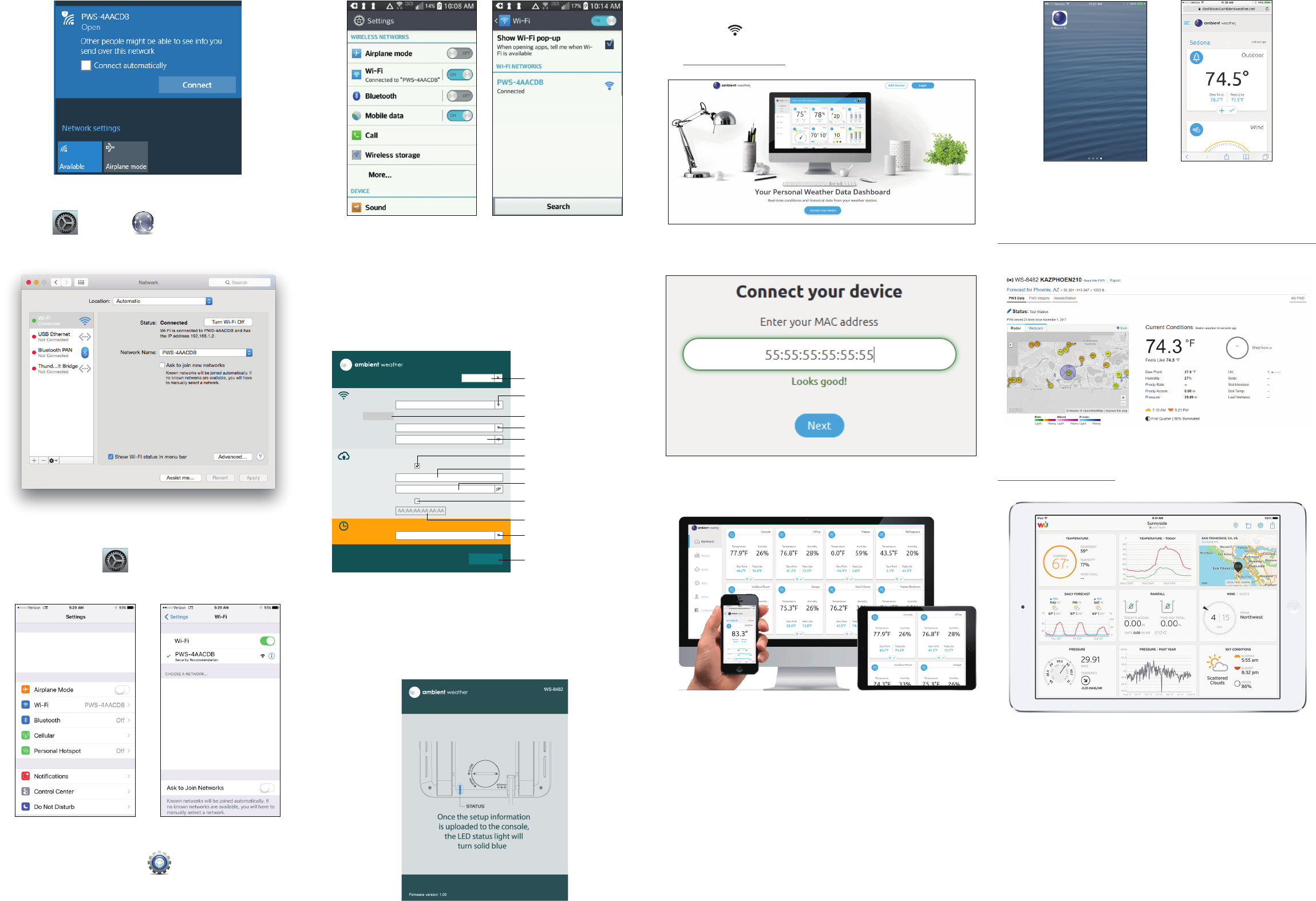
Figure 22
b) Example 2. Connect to the console WiFi server with a Mac. Choose the
Settings icon and Network . Connect to the PWS- WiFi network, as
shown in Figure 23 (your WiFi network name may be slightly different, but will
always begin with PWS-).
Figure 23
c) Example 3. Connect to the console WiFi server with an iPhone or iPad.
Choose the Settings icon and Wi-Fi (Figure 24). Connect to the PWS-
WiFi network, as shown in Figure 25 (your WiFi network name may be slightly
different, but will always begin with PWS-).
Figure 24 Figure 25
d) Example 4. Connect to the console WiFi server with an Android. From the
Apps icon, choose the Settings icon and Wi-Fi (Figure 26). Connect to
the PWS- WiFi network, as shown in Figure 27 (your WiFi network name may
be slightly different, but will always begin with PWS-).
Figure 26 Figure 27
3. Once connected, enter the following IP address into any browser’s address bar:
http://192.168.1.1
to access the console’s web interface:
Note: Some browsers will treat 192.168.1.1 as a search, so make sure you include
the header http://, or:
http://192.168.1.1 not 192.168.1.1
4. Enter the following information into the web interface (Figure 28). Make sure all of
the information is entered prior to selecting Apply. If you choose not to use
Wunderground.com or AmbientWeather.net, leave the check boxes unchecked.
WiFi Router setup
Upload wunderground.com
Station ID:
Weather server setup
Station key:
Server URL: nist.time.gov
Time server setup
Firmware version: 1.00
WS-8482
Router:
Add Router
Apply
Security type:
Router Password:
WAP2
ROUTER_A
Upload ambientweather.net
Mac address:
Select web interface language
Select your WiFi Router (SSID)
from the list
Manually enter your SSID if not on the list
(Press to show the blank)
Select your router’s security (usually WAP2)
Router’s password
(leave blank if unsecured)
Tick to confirm upload to
Weather underground server
Enter Station ID
Enter station key / password
Tick to confirm upload to
Ambient weather server
Mac address for Ambient weather server
registration
Select Time server
Press Apply to confirm the setting
Language: English
Figure 28
Notes:
• Make a note of your Mac address. You will need this to register at AmbientWeather.
net.
• Hidden SSIDs. If you have a hidden SSID, enter the SSID manually.
5. If all of the information you entered, and is correct, the console LED will change
from flashing blue to solid blue. If it keeps flashing, check your web interface
information again.
Figure 29
6. Once the setup is completed, the Wi-Fi console will disconnect from your computer
or smart phone’s Wi-Fi connection, and search for the assigned router. If the
connection is successful, the Wi-Fi console’s status LED will change to blue and
the Wi-Fi icon will stop ashing and remain on.
9.3 Register with AmbientWeather.net
Visit: www.AmbientWeather.net to create an account and select Add Device, as
shown in Figure 30
Figure 30
Next, enter the MAC address found on your Weather Station Web Interface (Figure
28). Note that this is an example only and your MAC address will be different.
Figure 31
Register an account on AmbientWeather.net (email address and password).
Once registered, select the dashboard to view your data, as shown in Figure 32.
Figure 32
AmbientWeather.net is a responsive design and mobile friendly, so there is no
need for a mobile app. Simply open your mobile devices web browser, browse to
AmbientWeather.net, and bookmark your dashboard. If you save the bookmark
to your desktop, it will automatically save the Ambient Weather icon, as shown in
Figure 33.
Figure 33
9.4 Viewing your Data on Weather Underground
There are several ways to view your data on Wunderground:
9.4.1 Web Browser
Visit:
http://www.wunderground.com/personal-weather-station/dashboard?ID=STATIONID
where STATIONID is your personal station ID (example, KAZPHOEN210).
Figure 34
9.4.2 WunderStation iPad Application
Visit:
http://www.WunderStation.com
to download the WunderStation iPad app.
Figure 35
3
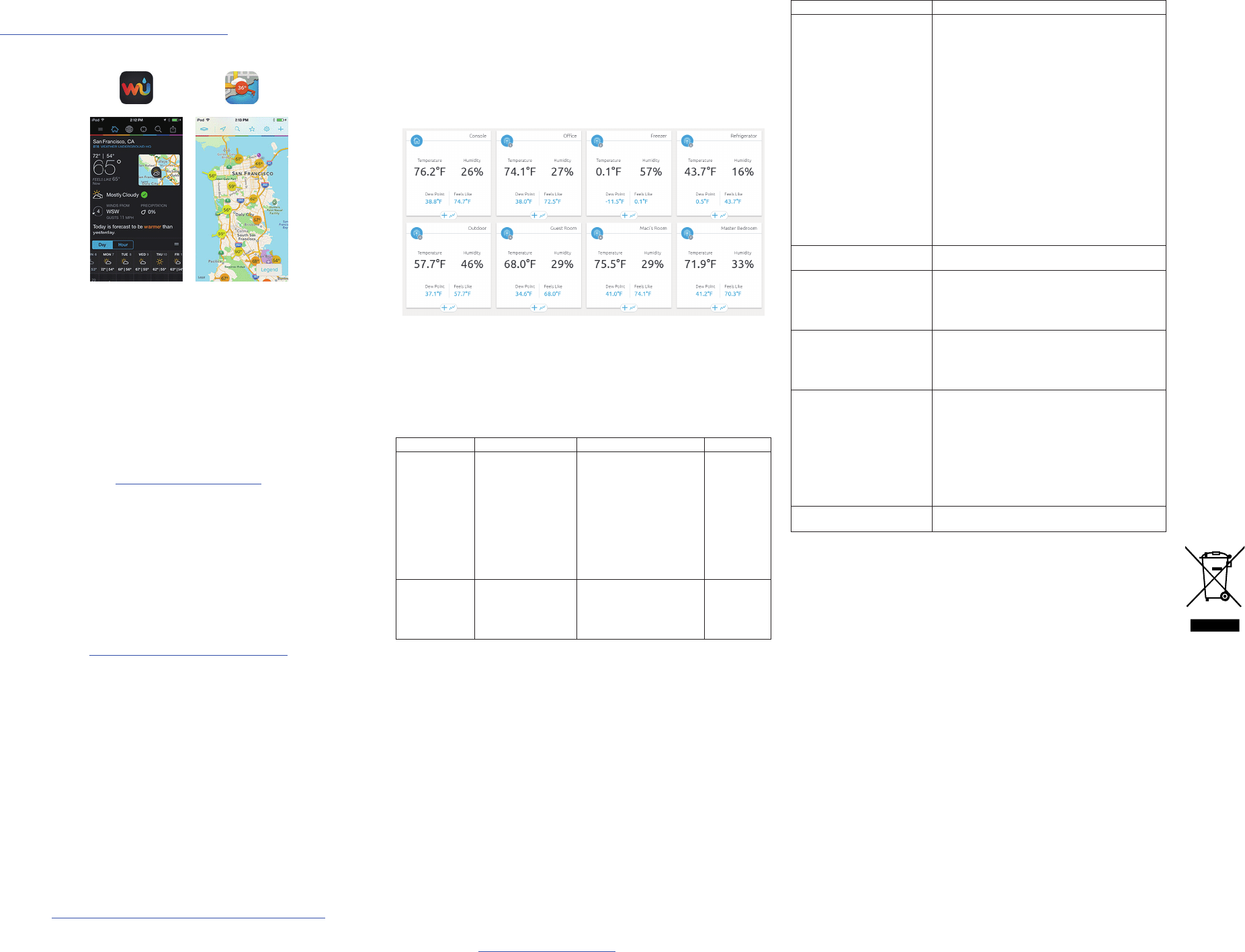
9.4.3 Mobile Apps
Visit:
http://www.wunderground.com/download/index.asp
for a complete list of Mobile apps for iOS and Android. Alternately, you can nd your
data on your mobile device’s web browser
Figure 36
9.5 Additional AmbientWeather.net Features
9.5.1 IFTTT
The AmbientWeather.net service connects to IFTTT, the platform that allows devices
and services to work together seamlessly.
Here are a few things you can do with IFTTT:
• Turn off your Rachio sprinklers when it rains, there is too much wind, or below
freezing.
• Close your Hunter blinds when the sun is too intense.
• Close your garage door when it is too windy.
• Blink your hue lights when it starts raining.
• Connect to other web services, such as Gmail, Facebook, Instagram, or Pinterest.
For more information on IFTTT and how it can work for you, visit:
https://ifttt.com/ambient weather
9.5.2 Compatible with Alexa
The Ambient Weather skill provides Ambient Weather personal weather station
owners with the ability to get real-time, and past weather information generated by
the devices they have set up at AmbientWeather.net.
Enable the skill and get started: say "Alexa, ask Ambient Weather for a weather
report.". This will provide you with your outdoor weather report, but you can ask for
your indoor weather report as well by saying, "Alexa, ask Ambient Weather about
the indoor conditions." You can also ask for a report about a specic day, month or
year! Just say "Alexa, ask Ambient Weather about the weather yesterday." or "Alexa,
ask Ambient Weather about the weather in May".
For more information and to enable this skill, visit:
https://www.amazon.com/dp/B074PGCM1D/
9.5.3 Works with Google Assistant
The Ambient Weather Google Assistant app provides Ambient Weather personal
weather station owners with the ability to get real-time, and past weather information
generated by the devices they have set up at AmbientWeather.net
Link your account to get started: say 'hey google, Ambient Weather... weather
report.' This will provide you with your outdoor weather report. You can ask for your
indoor weather report as well by saying, ' indoor conditions'.
You can also link the Ambient Weather app by downloading the Google Assistant.
Here are some sample commands:
• Weather Report
• Outdoor conditions
• Indoor conditions
• Yesterday’s weather
• Conditions for October 15, 2017
• Conditions for September 2017
• Conditions for 2016
For more information and to enable this app, visit:
https://assistant.google.com/services/a/id/668e6f3369f27209/
10. Maintenance
10.1 Adding or Subtracting Multiple Sensors
If you add or subtract multiple wireless sensors, you will need to synchronize the
sensors.
10.1.1 Adding or Subtracting Sensors
1. Make sure each sensor is on a different channel and in sequence (1, 2, 3, ..) before
powering up. Insert the batteries.
If already powered up, press the reset button inside the battery compartment.
Reference Section 3.1.2 for details.
2. Place each sensor about 5 to 10 feet from the console.
3. Press the SENSOR button on the back of the console to begin synchronization.
Reference Section 3.1.1 for details.
4. Do not touch any buttons until synchronization is complete.
10.1.2 Multiple Sensor Features
The console will scroll through the multiple channels, so there is no need to press
the Channel button. Reference Section 7.7.1.1 for details.
Wunderground.com does not support multiple sensor channels. However,
AmbientWeather.net does support multiple channels.
The AmbientWeather.net dashboard allows you to rename the sensor description,
as shown in Figure 37.
Figure 37
11. Specications
11.1 Wireless Specications
• Indoor/Outdoor Thermo-Hygrometer: 300 feet line of sight, 100 feet under most
conditions.
• Frequency: 915 MHz
11.2 Measurement Specications
The following table provides specications for the measured parameters.
Measurement Range Accuracy Resolution
Indoor and
Outdoor
Temperature
-4 to 140 °F alkaline
batteries
-40 to 140 °F Lithium
e2 Energizer batteries
131 to 140°F: ± 0.9°F
(55 to 60°C: ± 0.5°C)
50 to 131°F: ± 0.7°F
(10 to 55°C: ± 0.4°C)
- 4 to 50°F: ± 2.3°F
(-20 to 10°C: ± 1.3°C)
- 40 to - 4°F: ± 3.4°F
(-40 to -20°C: ± 1.9°C)
0.1 °F/°C
Indoor and
Outdoor
Humidity
1 to 99% 0 to 90% RH ± 2.5% RH @
77°F (25°C)
90 to 100% RH ± 3.5% RH
@ 77°F (25°C)
1%
11.3 Power Consumption
• Display backup power: 1 x CR2032 button cell (included)
• Display: DC 5V, 1.0A 100-240V 50 / 60 Hz UL rated Class 5 adaptor
• Indoor/Outdoor Thermo-Hygrometer Sensor: 2 x AA Alkaline or Lithium e2 Energizer
for cold weather batteries (not included)
11.4 WiFi Specications
• WIFI Standard: 802.11 b/g/n
• Wi-Fi Operating frequency: 2.4G
• Setup User Interface (UI) support setup device: Build-in WiFi with WAP mode smart
device, including laptops, computers, smart phones and smart pads.
• Recommend web browser for setup UI: Web browser support of HTML 5, such as
the latest versions of Chrome, Safari, IE, Edge, Firefox or Opera.
11.5 Other Specications
• Time synchronize method: Synchronized through internet UTC time server
• Console Temperature Limits of Operation: 23 ˚F to 122 ˚F (-5˚C to 50˚C)
11.6 Weight Specications
• Console: 0.5 lbs (220 grams) with battery
• Wireless Sensor: 0.32 lbs (144 grams) with batteries
12. Troubleshooting Guide
If your question is not answered here, you can contact us as follows:
1. Email Support: support@ambientweather.com
2. Technical Support: 480-346-3380 (M-F 8am to 3pm Arizona Time). Note that
Arizona does not observe Daylight Savings Time.
Problem Solution
The wireless sensor
communication has been lost
or is intermittent or will not
sync up.
•Make sure the transmitter is powered up and the
LED is ashing about once per minute. For cold
weather environments, install lithium batteries.
If the transmitter is not flashing, replace the
batteries.
• Resync the console. Reference Section 3.3.2.
•The maximum line of sight communication range
is 300’ (100’ under most conditions). Move the
sensor closer to the console.
•If the sensor is too close (less than 5-10’), move
the sensor away from the console.
•Make sure the remote sensors are not
transmitting through solid metal (acts as an RF
shield), or earth barrier (down a hill).
•Move the console away from electrical noise
generating devices, such as computers, TVs and
other wireless transmitters or receivers.
•Radio Frequency (RF) Sensors cannot transmit
through metal barriers (example, aluminum
siding) or multiple, thick walls.
The console does not respond
to commands.
• Press the reset button on the back of the console
with an open ended paper clip or sharp tool.
Cannot connect the console to
WiFi
• Check your WiFi password is correct.
•Make sure your device (desktop, laptop, tablet or
phone) is connected to your WiFi router.
•If you own a dual band router (2.4 and 5 GHz),
make sure your WiFi 2.4 GHz band is turned on.
AmbientWeather.net is not
updating
•Make sure your MAC address was entered
correctly.
Make sure the checkbox is checked in the web
panel (reference Figure 28).
Wunderground.com is not
updating
•Make sure the checkbox is checked in the web
panel (reference Figure 28).
•Make sure your station ID and Station Key are
correct (reference Figure 30).
•DO NOT copy and paste your station key into
the console’s web display, as it will add a lagging
space. Make sure you type it in. Also, it is easy
to confuse the lower case letter l, upper case I
and the number 1, as well as the number 0 and
the letter O.
Console Time is off by
increments of hours.
Make sure your time zone and Daylight Savings
Time are set properly (Reference Section 7.1.1).
13. Liability Disclaimer
Please help in the preservation of the environment and return used batteries to an
authorized depot.
The electrical and electronic wastes contain hazardous substances. Disposal of
electronic waste in wild country and/or in unauthorized grounds strongly damages
the environment.
Reading the “User manual” is highly recommended. The manufacturer and supplier
cannot accept any responsibility for any incorrect readings and any consequences
that occur should an inaccurate reading take place.
This product is designed for use in the home only as indication of weather conditions.
This product is not to be used for medical purposes or for public information.
The specications of this product may change without prior notice. This product is not
a toy. Keep out of the reach of children. Place the main console at least 20cm from
nearby persons.
No part of this manual may be reproduced without written authorization of the
manufacturer.
Ambient, LLC WILL NOT ASSUME LIABILITY FOR INCIDENTAL,
CONSEQUENTIAL, PUNITIVE, OR OTHER SIMILAR DAMAGES ASSOCIATED
WITH THE OPERATION OR MALFUNCTION OF THIS PRODUCT.
14. FCC Statement
This device complies with Part 15 of the FCC Rules. Operation is subject to the
following two conditions: (1) this device may not cause harmful interference, and (2)
this device must accept any interference received, including interference that may
cause undesired operation.
Warning: Changes or modications to this unit not expressly approved by the party
responsible for compliance could void the user's authority to operate the equipment.
NOTE: This equipment has been tested and found to comply with the limits for
a Class B digital device, pursuant to Part 15 of the FCC Rules. These limits
are designed to provide reasonable protection against harmful interference in
a residential installation. This equipment generates, uses and can radiate radio
frequency energy and, if not installed and used in accordance with the instructions,
may cause harmful interference to radio communications.
However, there is no guarantee that interference will not occur in a particular
installation. If this equipment does cause harmful interference to radio or television
reception, which can be determined by turning the equipment off and on, the user
is encouraged to try to correct the interference by one or more of the following
measures:
• Reorient or relocate the receiving antenna.
• Increase the separation between the equipment and receiver.
• Connect the equipment into an outlet on a circuit different from that to which
the receiver is connected.
• Consult the dealer or an experienced radio/TV technician for help.
The Responsible party:
Company Name: Ambient, LLC
Address : 6845 W. Frye Road Chandler, AZ 85226
Phone : 1-(480)346-3380
15. Warranty Information
Ambient, LLC provides a 1-year limited warranty on this product against
manufacturing defects in materials and workmanship.
This limited warranty begins on the original date of purchase, is valid only
on products purchased and only to the original purchaser of this product. To
receive warranty service, the purchaser must contact Ambient, LLC for problem
determination and service procedures.
Warranty service can only be performed by an Ambient, LLC. The original dated bill
of sale must be presented upon request as proof of purchase to Ambient, LLC.
Your Ambient, LLC warranty covers all defects in material and workmanship with the
following specied exceptions: (1) damage caused by accident, unreasonable use or
neglect (lack of reasonable and necessary maintenance); (2) damage resulting from
failure to follow instructions contained in your owner’s manual; (3) damage resulting
from the performance of repairs or alterations by someone other than an authorized
Ambient, LLC authorized service center; (4) units used for other than home use (5)
applications and uses that this product was not intended (6) the products inability
to receive a signal due to any source of interference or metal obstructions and (7)
extreme acts of nature, such as lightning strikes or oods.
This warranty covers only actual defects within the product itself, and does not
cover the cost of installation or removal from a fixed installation, normal set-up
or adjustments, claims based on misrepresentation by the seller or performance
variations resulting from installation-related circumstances.
4
FCC RF Radiation Exposure Statement
Caution: To maintain compliance with the FCC’s RF exposure guidelines, place
the unit at least 20cm from nearby persons.