CETIS CETIS501 Telephone User Manual E103 IP v1 0
CETIS,INC. Telephone E103 IP v1 0
UserManual.wiki
>
CETIS
>
CETIS501 User Manual
Users Manual
Navigation menu
Upload a User Manual
Namespaces
Wiki Guide
HTML
PDF
Info
Views
User Manual
Discussion / Help
Navigation
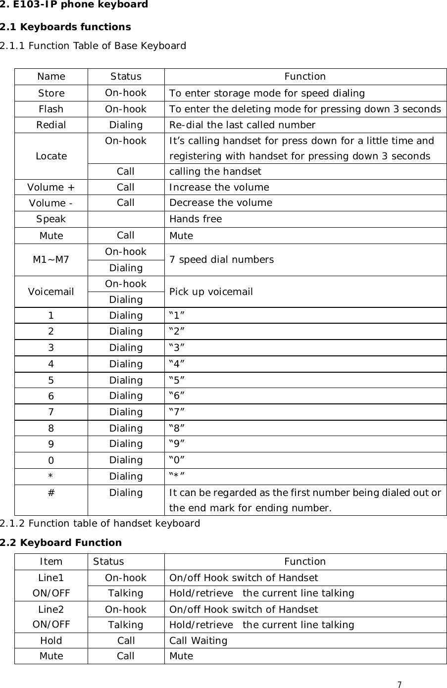
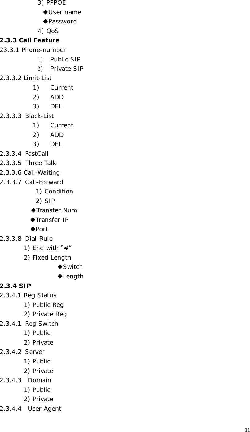
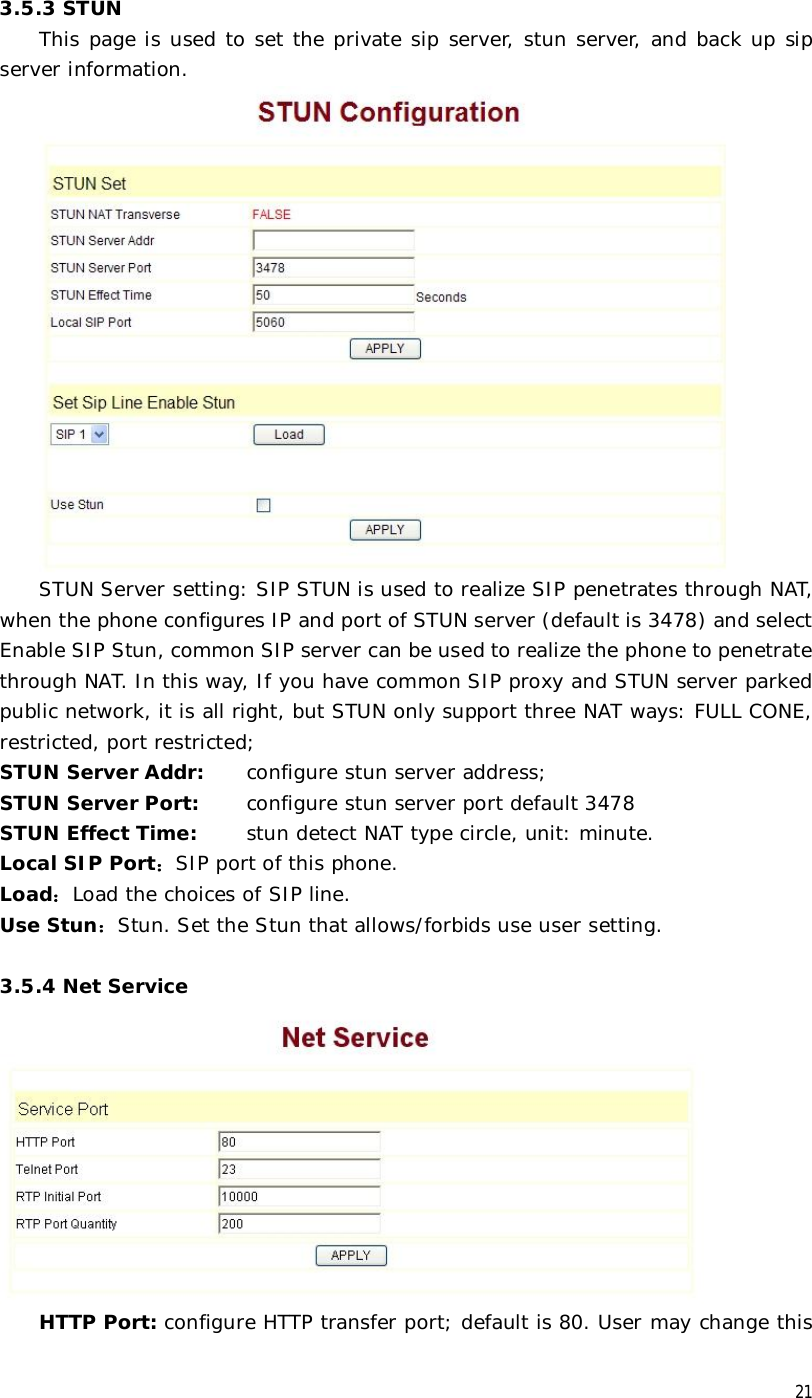
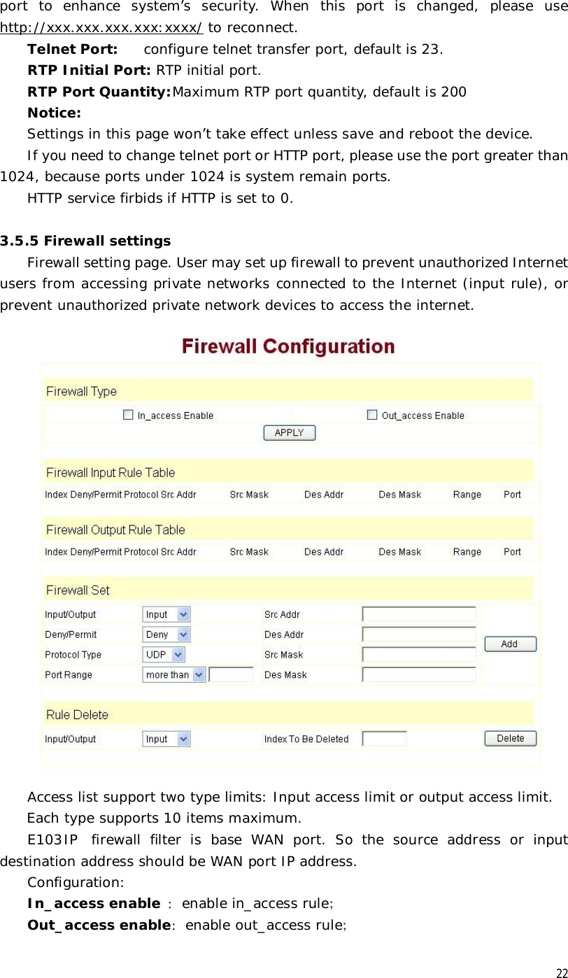
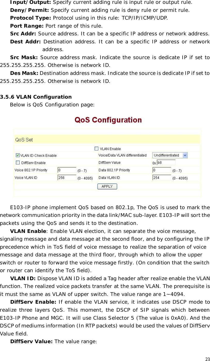
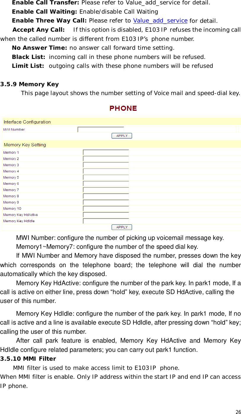
![24 0x28,0x30,0x38,0x48,0x50,0x58,0x68,0x70,0x78,0x88,0x90,0x98,0xb8.default is 0xb8 ,oxb8 stands for best fast transmission; 28-38 is guarantee for the transmission priority for the 1st rank , 48-58 is guarantee for the transmission priority for the 2nd rank, 68-78 is guarantee for the transmission priority for the 3rd rank, 88-98 is guarantee for the transmission priority for the 4th rank. 802.1P Priority: The priority of 802.1p 3.5.7 Digital Map Digit map is a set of rules to determine when the user has finished dialing. E103IP support below digital map: Digital Map is based on some rules to judge when user end their dialing and send the number to the server. E103IP support following digital map: ----End With “#”:Use # as the end of dialing. ----Fixed Length::When the length of the dialing is matched, the call will be sent. ----Timeout::Specify the timeout of the last dial digit. The call will be sent after timeout ----Prefix::User define digital map: [ ]:Represents the range of digit, can be a range such as [1-4], or use comma such as [1, 3, 5], or use a list such as [234] x :Represents any one digit between 0~9 Tn:Represents the last digit timeout. n represents the time from 0~9 second, it is necessary. Tn must be the last two digit in the entry. If Tn is not included in the entry, we use T0 as default, it means system will sent the number immediately if the number matches the entry. Example: 8[2-9]xxxxx: :All number from 8200000 to 8899999 will be sent](https://usermanual.wiki/CETIS/CETIS501/User-Guide-1691071-Page-24.png)
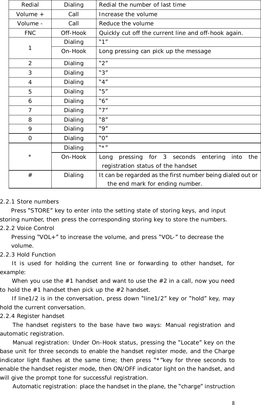
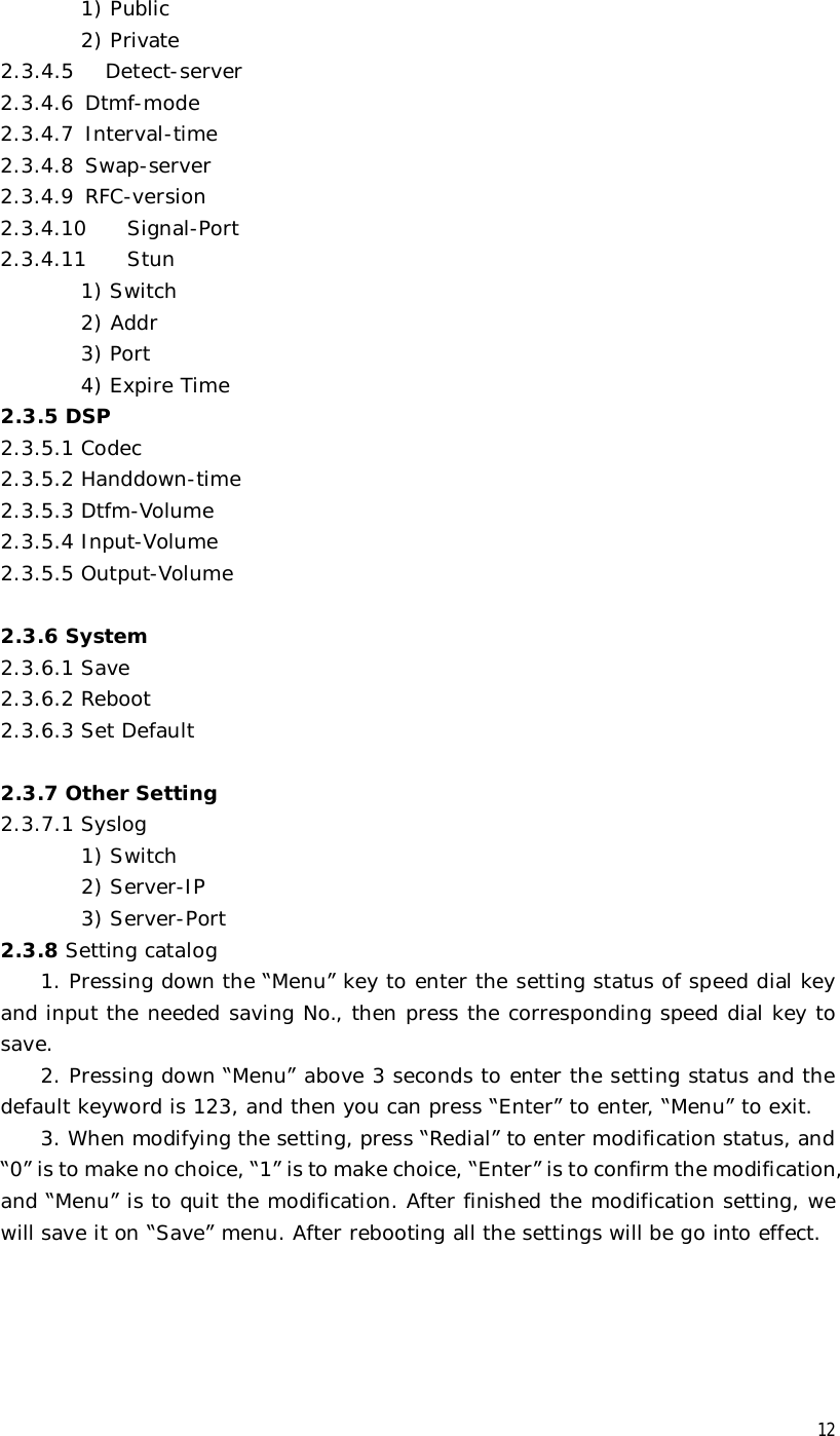
![25 immediately. 955xx:5 digits numbers begin with 9 will be sent immediately. 10060:Number 10060 will be sent will be immediately 22xxxxxT1:7 digits numbers begin with 22 will be sent after one second 39[3,9]xxxx :7 digits numbers begin with 393 or 399 will be sent immediately. 3.5.8 Call Service Settings User configure the value add service such as hotline, call forward, call transfer, call waiting, 3-way conference call, auto-answer, etc in this page。 Hotline: configure hotline number. Warm Line Time:Set waiting time for the user picking up the phone to dial hotline number, the config range is 0-9s, default is 0s. If warm line time is 0s, then hotline number will be sent right away after off-hook; If the range is 1-9s, take 3s as an example, hotline number will be sent immediately 3s later without pressing any key. As long as any key is pressed within the setting time, timer will be suspended. Auto Answer: Enable/disable auto answer function. No Disturb: DND, do not disturb, enable this option to refuse any calls. Ban Outgoing: Enable this to ban outgoing calls.](https://usermanual.wiki/CETIS/CETIS501/User-Guide-1691071-Page-25.png)