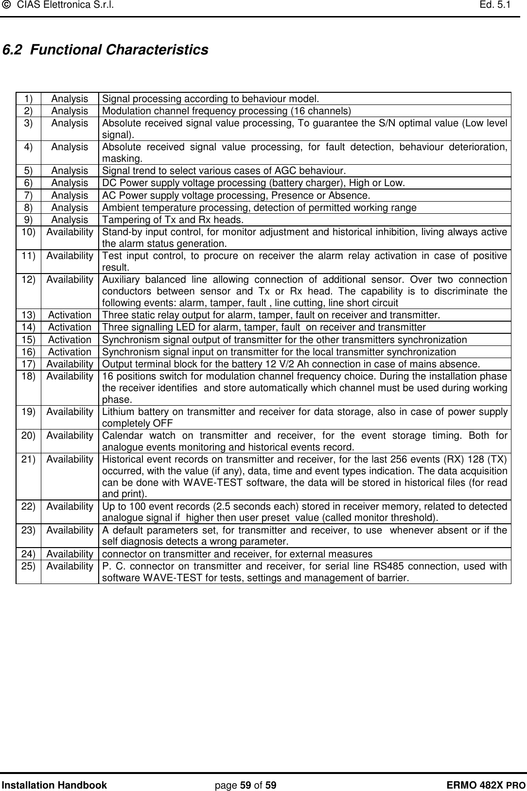
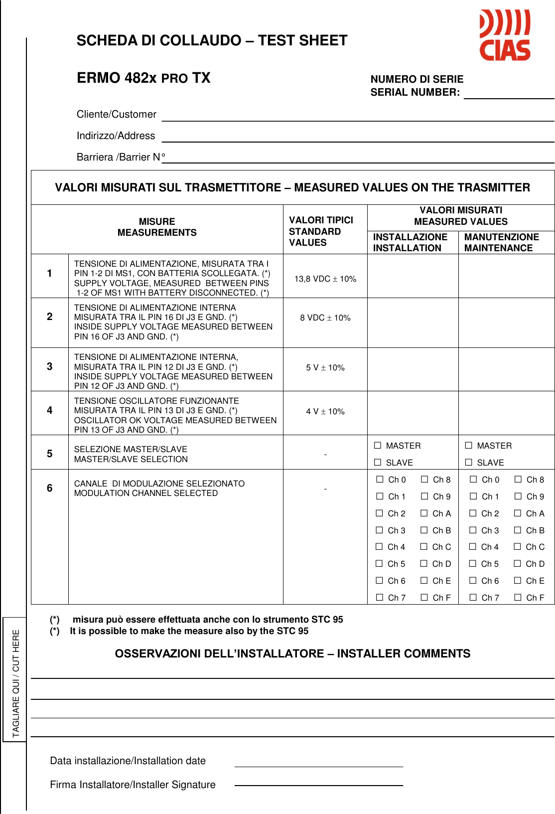
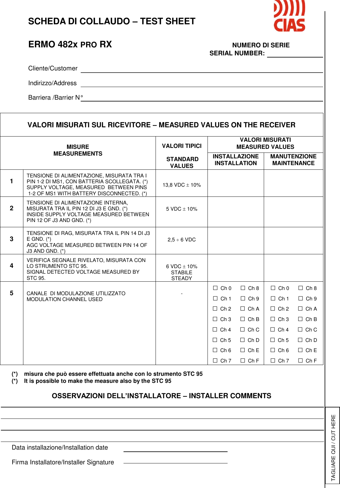
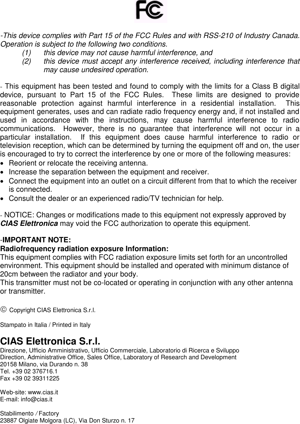
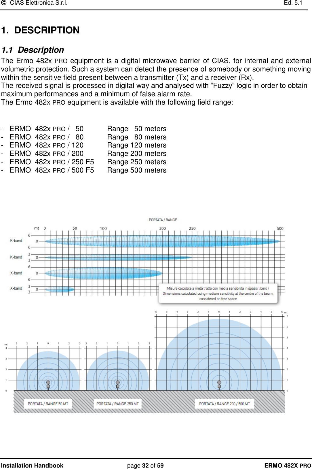
CIAS Elettronica S R L ERMO-482XPRO-K Microwave barrier User Manual Ermo 482x PRO
CIAS Elettronica S.R.L. Microwave barrier Ermo 482x PRO
UserManual.wiki
>
CIAS Elettronica S R L
>
ERMO 482XPRO K User Manual
User Manual
Navigation menu
Upload a User Manual
Namespaces
Wiki Guide
HTML
PDF
Info
Views
User Manual
Discussion / Help
Navigation


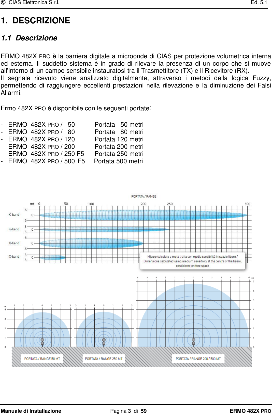
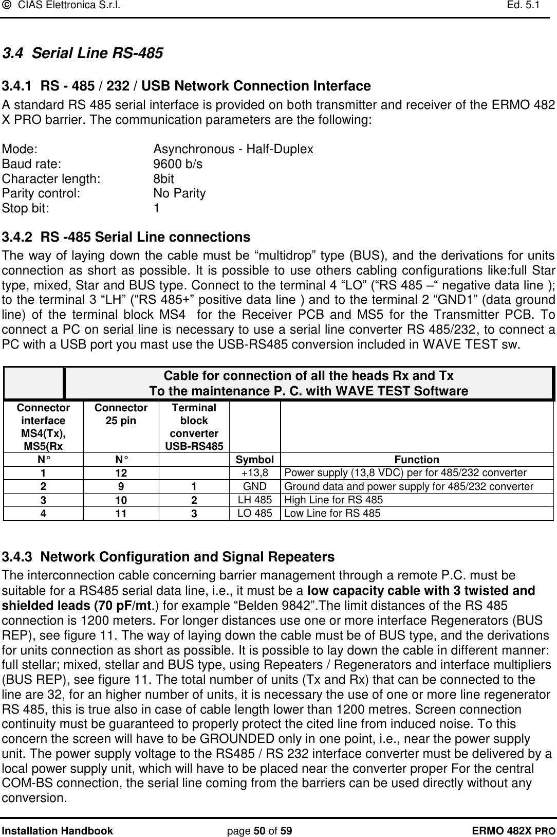
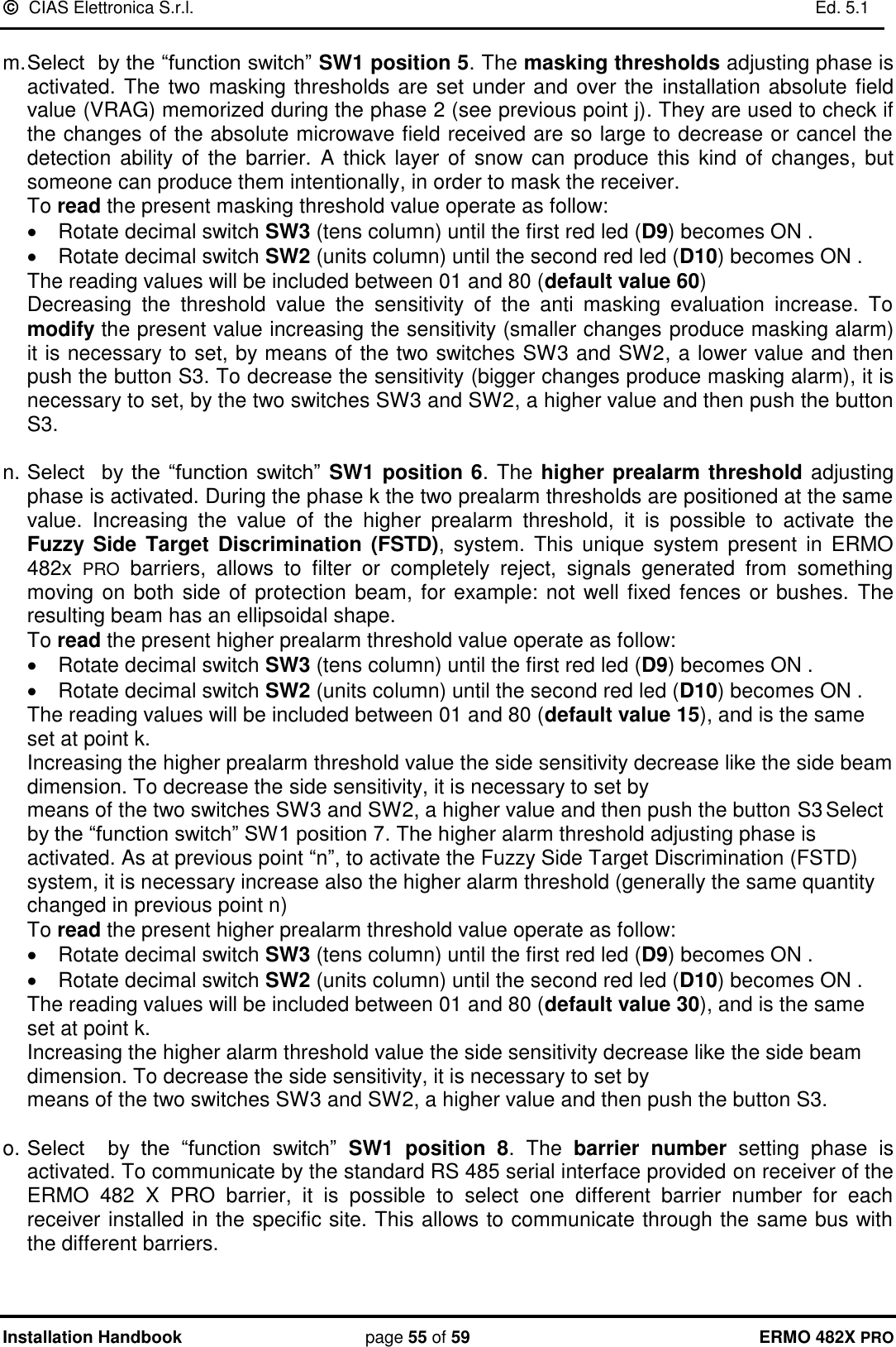
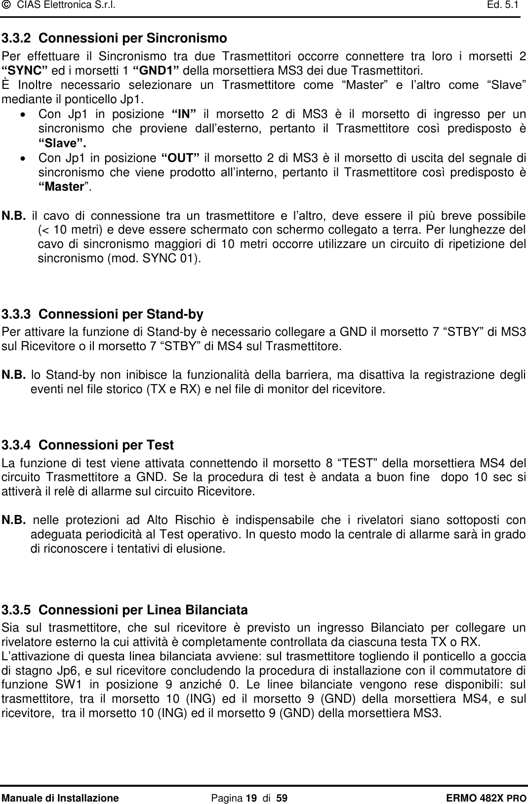
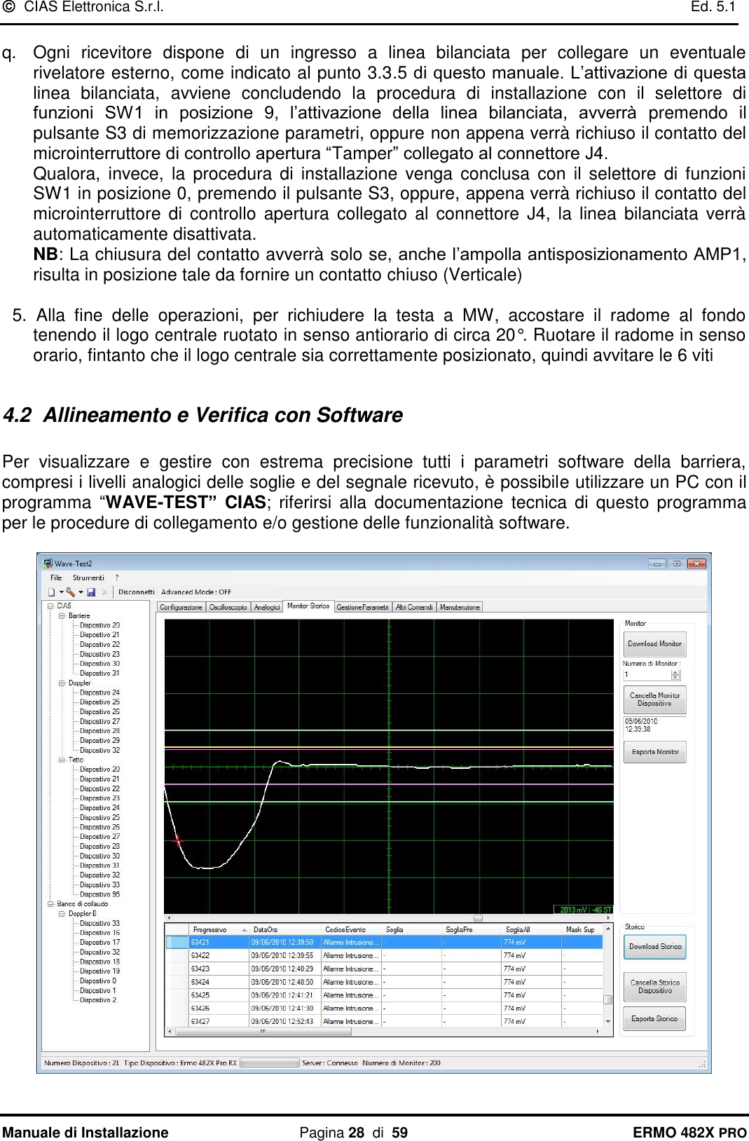
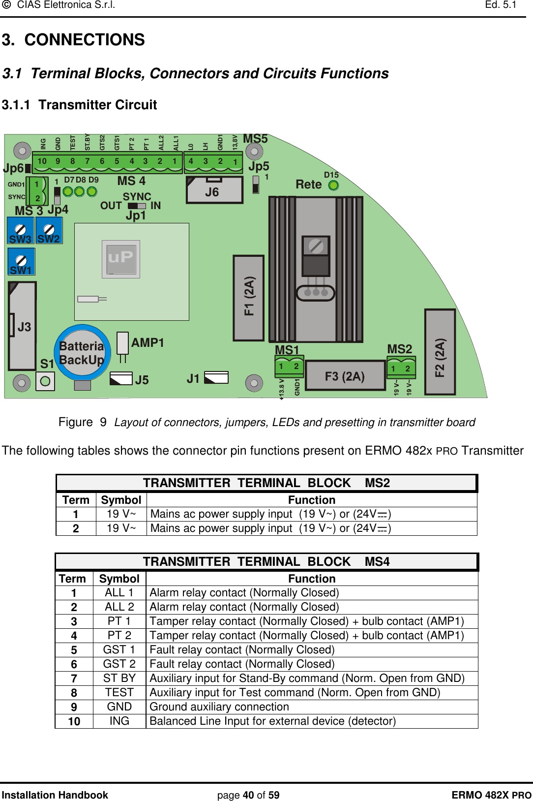
![ CIAS Elettronica S.r.l. Ed. 5.1 Manuale di Installazione Pagina 7 di 59 ERMO 482X PRO 2.5 Ampiezza dei Fasci Sensibili L'ampiezza del Campo Sensibile è in funzione sia del tipo di antenna impiegata, sia della distanza tra Trasmettitore e Ricevitore, sia dalla regolazione di sensibilità impostata. Le figure seguenti ci forniscono il diametro a metà tratta del Fascio Sensibile, in funzione della lunghezza della tratta, nel caso di sensibilità massima e minima per i diversi modelli di apparecchio impiegati. 12345678910510 15 20 25 30 35 40 45 50Diametro zonasensibilea metà tratta [m]SensibilitàMassimaLunghezzadella tratta [m]Sensibilitàminima Figura 3 Diametro della zona sensibile a metà tratta per ERMO 482X PRO / 50 20 40 60 80 100 120 140 160 180 200Diametro zonasensibilea metà tratta [m]SensibilitàMassimaLunghezzadella tratta [m]Sensibilitàminima2468101214161820 Figura 4 Diametro della zona sensibile a metà tratta per ERMO 482X PRO / 80-120-200](https://usermanual.wiki/CIAS-Elettronica-S-R-L/ERMO-482XPRO-K/User-Guide-1883626-Page-8.png)
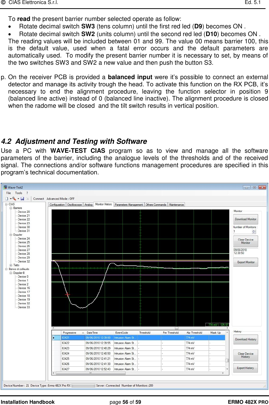
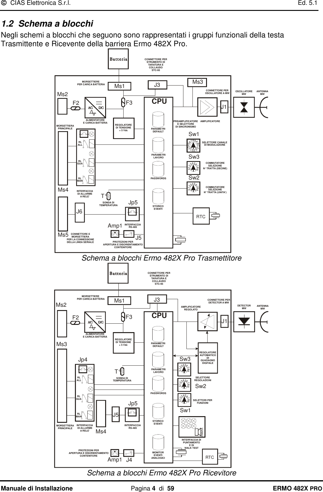
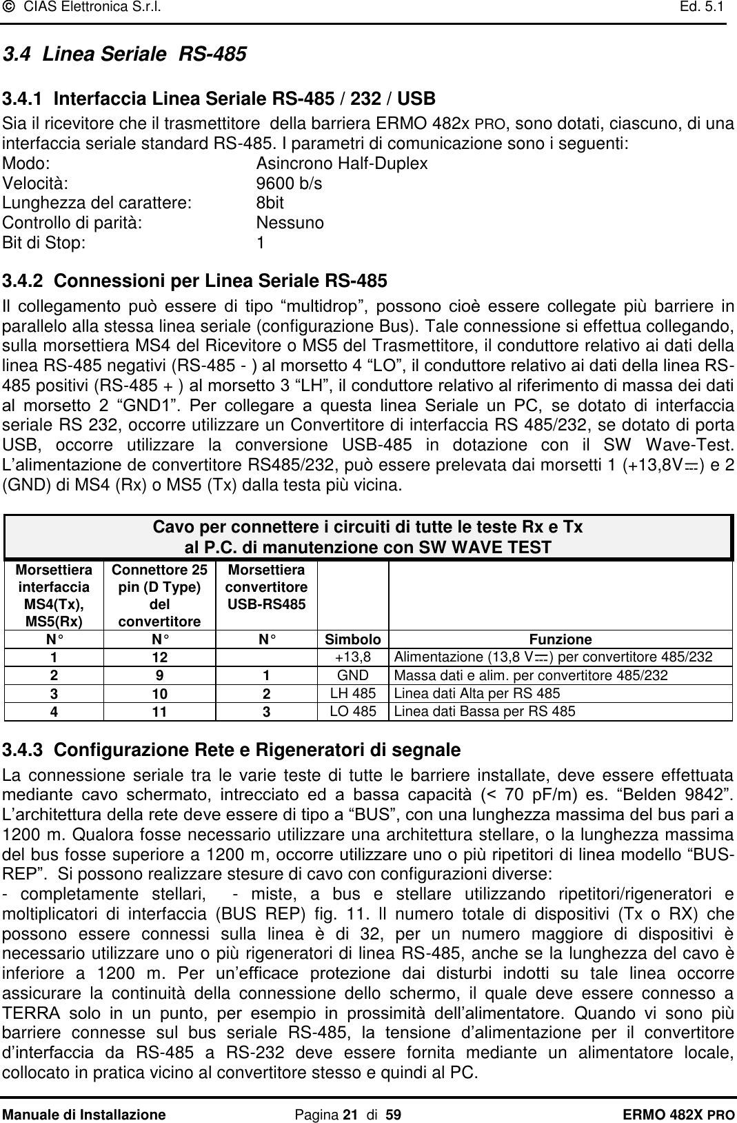
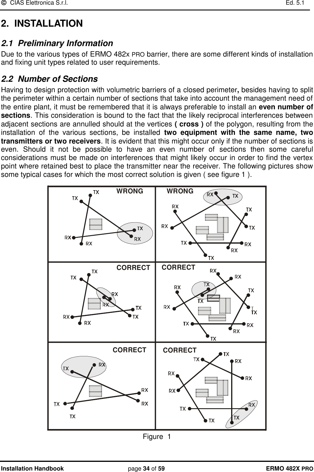
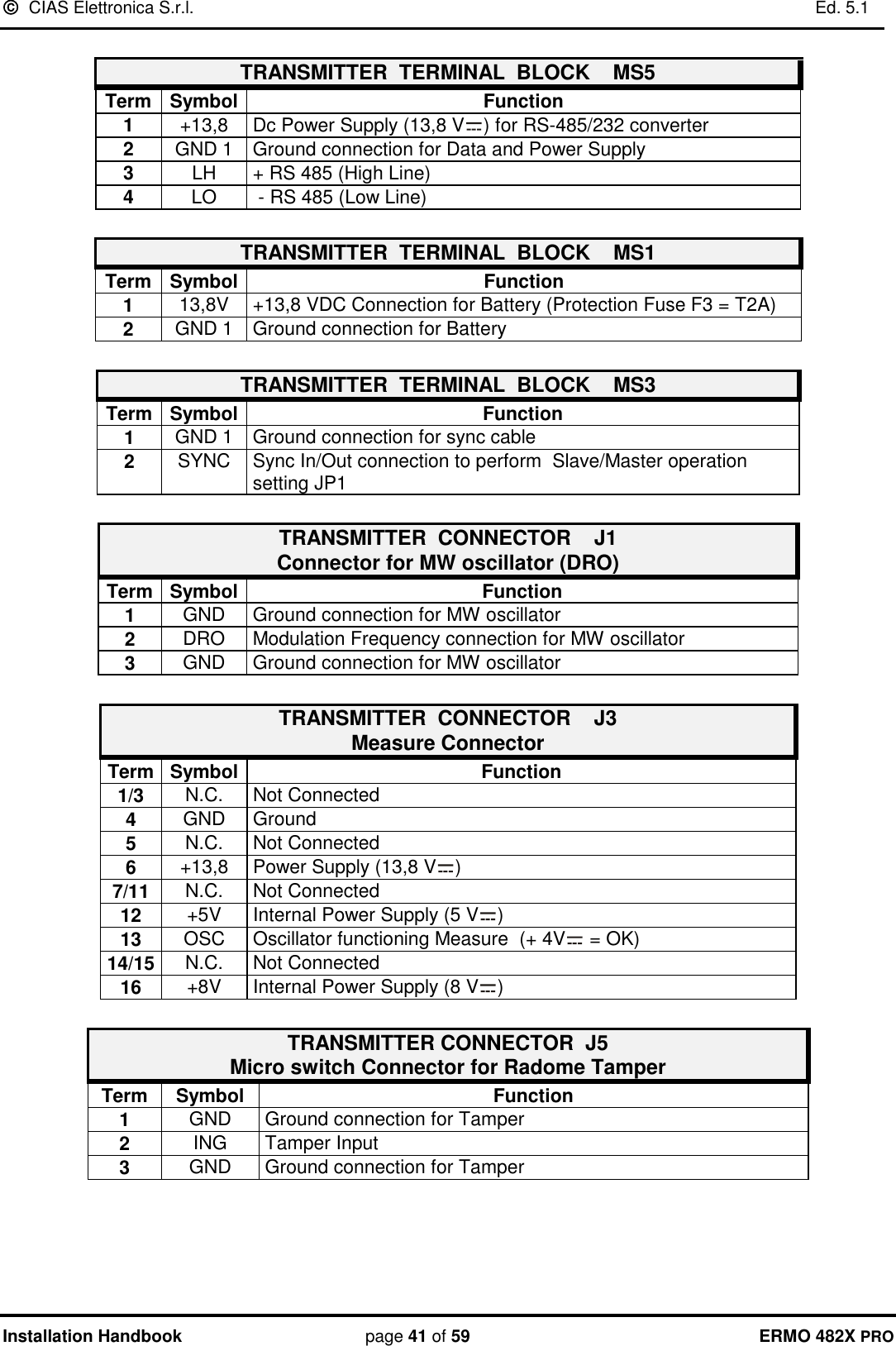
![ CIAS Elettronica S.r.l. Ed. 5.1 Manuale di Installazione Pagina 8 di 59 ERMO 482X PRO 51015202550 100 150 200 250 300 350 400 450 500Diametro zonasensibilea metà tratta [m]SensibilitàMassimaLunghezzadella tratta [m]Sensibilitàminima Figura 5 Diametro della zona sensibile a metà tratta per ERMO 482X PRO / 250-500 F5 Nota: è necessario ricordare che per l’apparato ERMO 482 X PRO, la regolazione di sensibilità deve essere presa in considerazione per ricavare la dimensione dei fasci sensibili a metà della tratta. Quanto più alte sono le soglie di preallarme e di allarme, tanto più bassa è la sensibilità e viceversa. È inoltre importante ricordare che la soglia di preallarme determina il livello di inizio elaborazione, cioè tutti i segnali che stanno al di sotto di tale soglia, sono considerati disturbo o rumore. Tutti i segnali che superano questa soglia, danno luogo alla elaborazione del segnale secondo le regole “Fuzzy” previste. Se, dopo aver superato la soglia di preallarme, il segnale di intrusione resta per circa 40 sec tra la medesima e la soglia di allarme viene generato un evento di “bersaglio fermo”, e si ha l’attivazione del relè di allarme. Le soglie di preallarme, di allarme e quindi la sensibilità, sono regolabili sia mediante i dispositivi integrati a bordo di ciascuna unità ricevente sia mediante il Software WAVE-TEST. Le impostazioni di default sono relative ad una sensibilità media adatta alla gran parte dei casi pratici.](https://usermanual.wiki/CIAS-Elettronica-S-R-L/ERMO-482XPRO-K/User-Guide-1883626-Page-9.png)
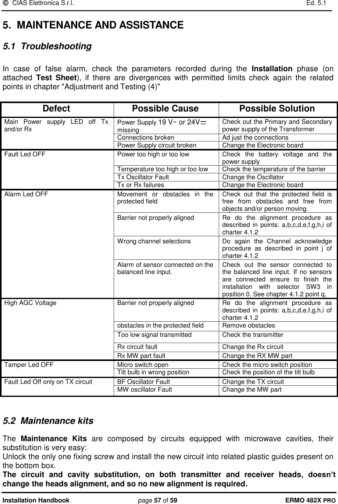
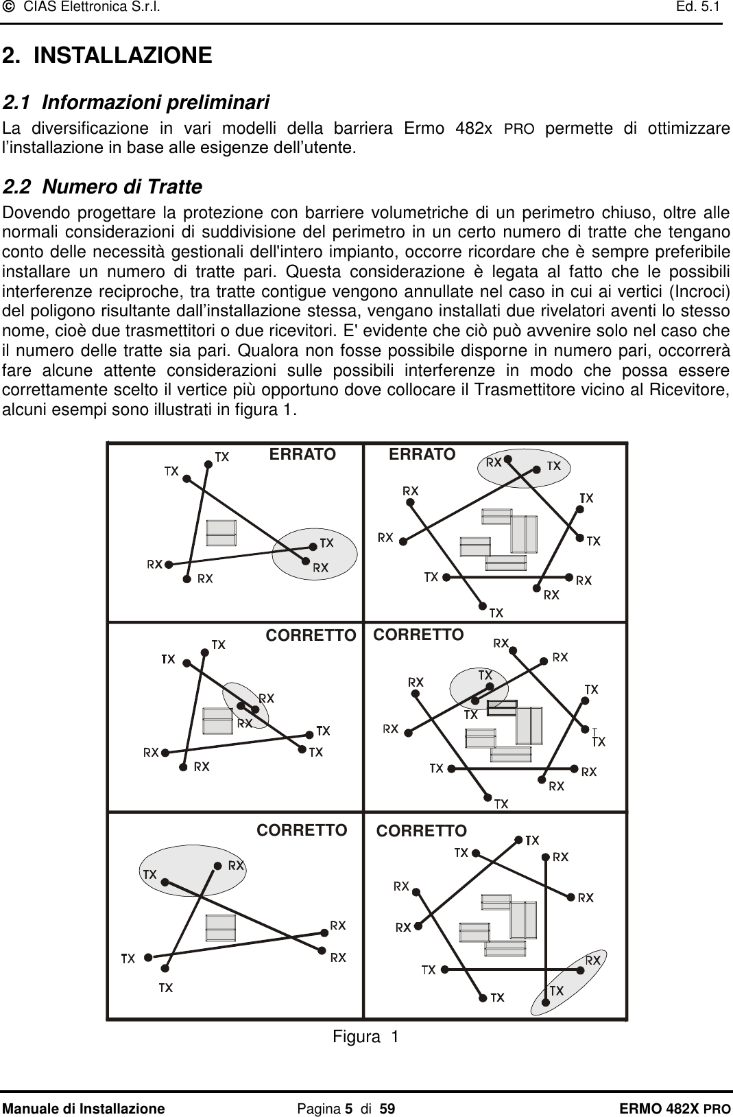
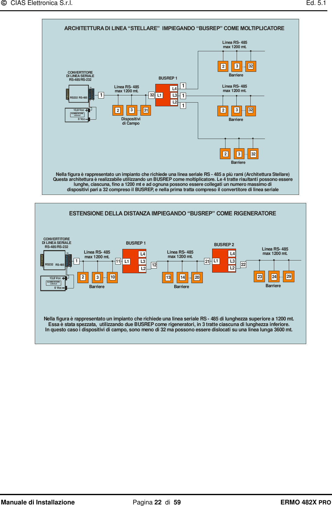
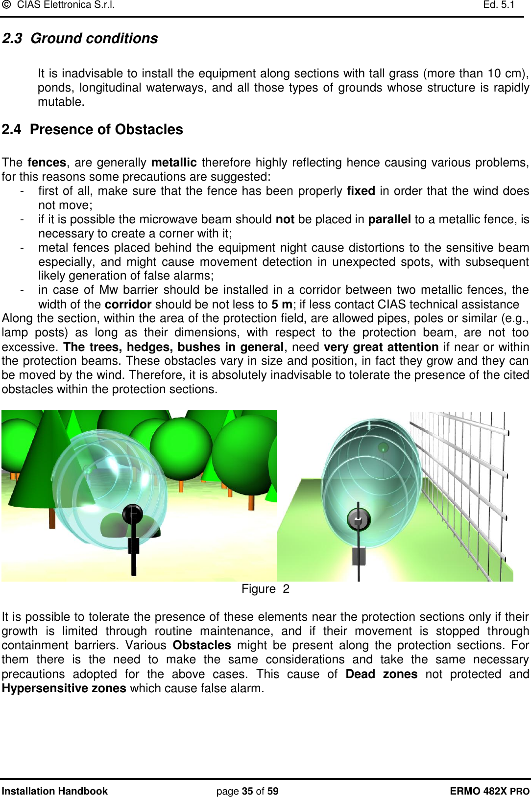
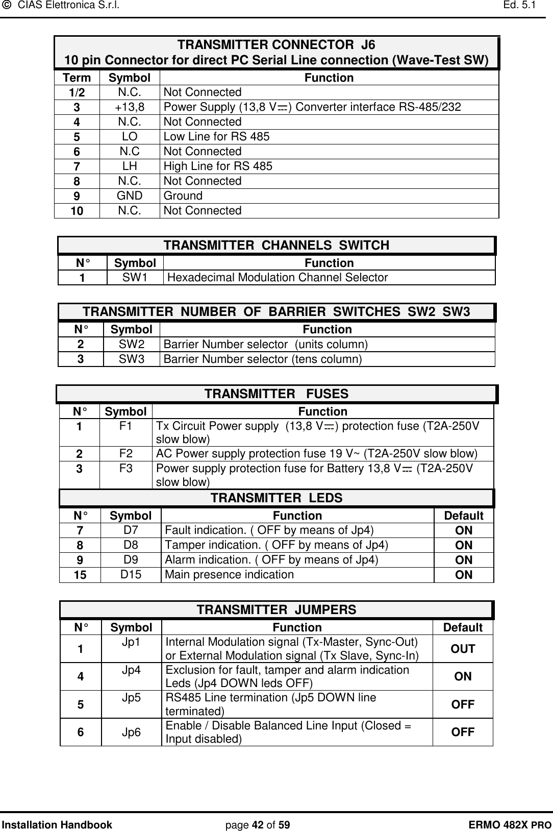
![ CIAS Elettronica S.r.l. Ed. 5.1 Manuale di Installazione Pagina 9 di 59 ERMO 482X PRO 2.6 Lunghezza delle Zone Morte in prossimità degli apparati La lunghezza delle Zone Morte in prossimità degli apparati è in funzione sia della distanza dell'apparato stesso dal suolo, sia della sensibilità impostata sul Ricevitore, sia del tipo di antenna impiegata (figure 6-7-8). L’Altezza consigliata per installazioni standard è di 80 cm circa (90cm circa per ERMO482X PRO 50-250-500), compatibilmente con le esigenze impiantistiche. La misura è da considerarsi tra il suolo e il centro dell'apparecchio. Con una sensibilità media, la distanza minima consigliata per effettuare l’Incrocio è di 5 m per le barriere da 80-120-200m, 12,5m per le barriere da 250-500m e di 3,5m per le barriere da 50m 203010405060708090100203010405060708090100123 4 5 67 8 9 10Altezza dal suoloal centroantenna [cm]SensibilitàMassimaLunghezzazona morta [m]Sensibilitàminima Figura 6 Lunghezza della zona morta in prossimità degli apparati in funzione dell’altezza dal centro degli stessi al suolo per ERMO 482x PRO. 50 203010405060708090100203010405060708090100123 4 5 67 8 9 10Altezza dal suoloal centroantenna [cm]SensibilitàMassimaLunghezzazona morta [m]Sensibilitàminima Figura 7 Lunghezza della zona morta in prossimità degli apparati in funzione dell’altezza dal centro degli stessi al suolo per ERMO 482x PRO. 80-120-200](https://usermanual.wiki/CIAS-Elettronica-S-R-L/ERMO-482XPRO-K/User-Guide-1883626-Page-10.png)
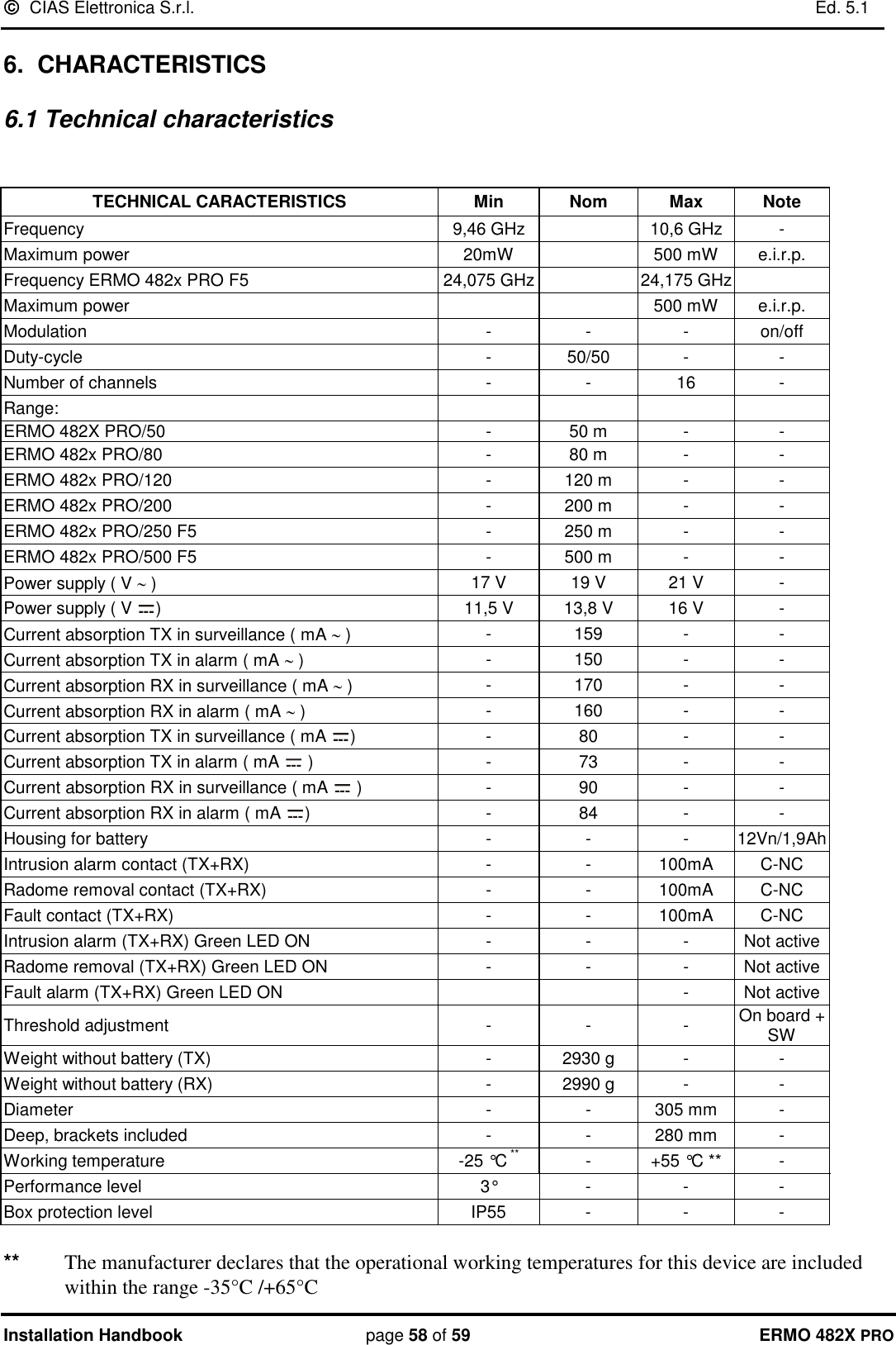
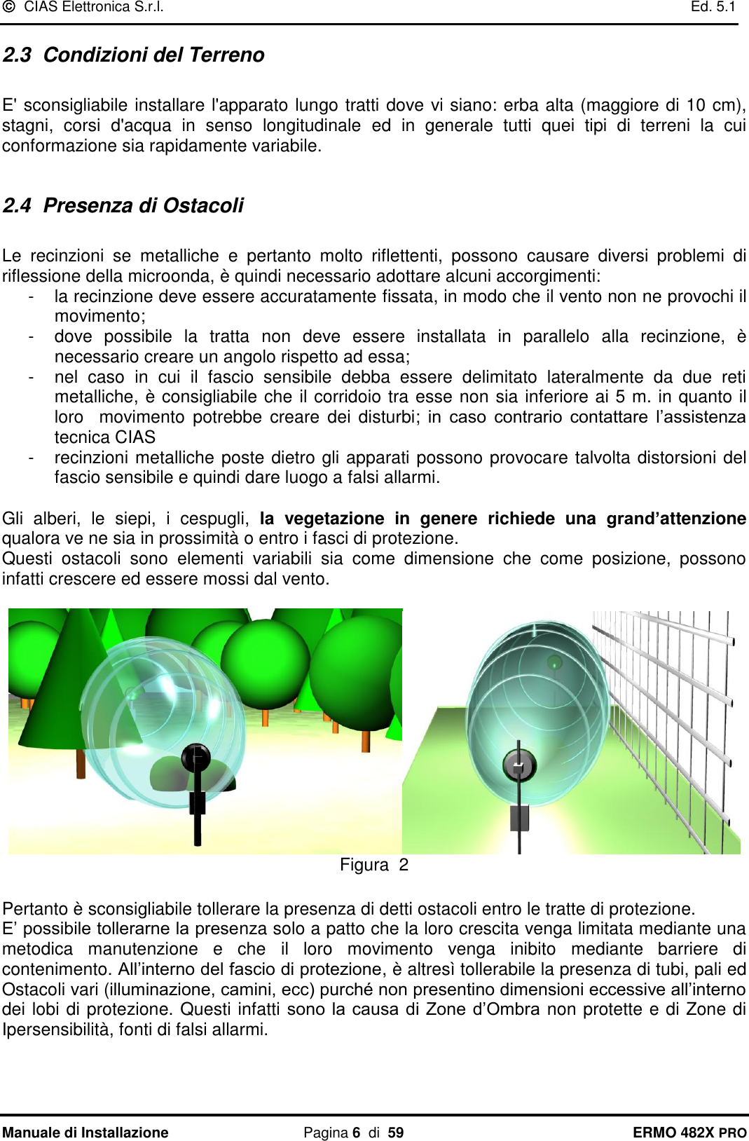
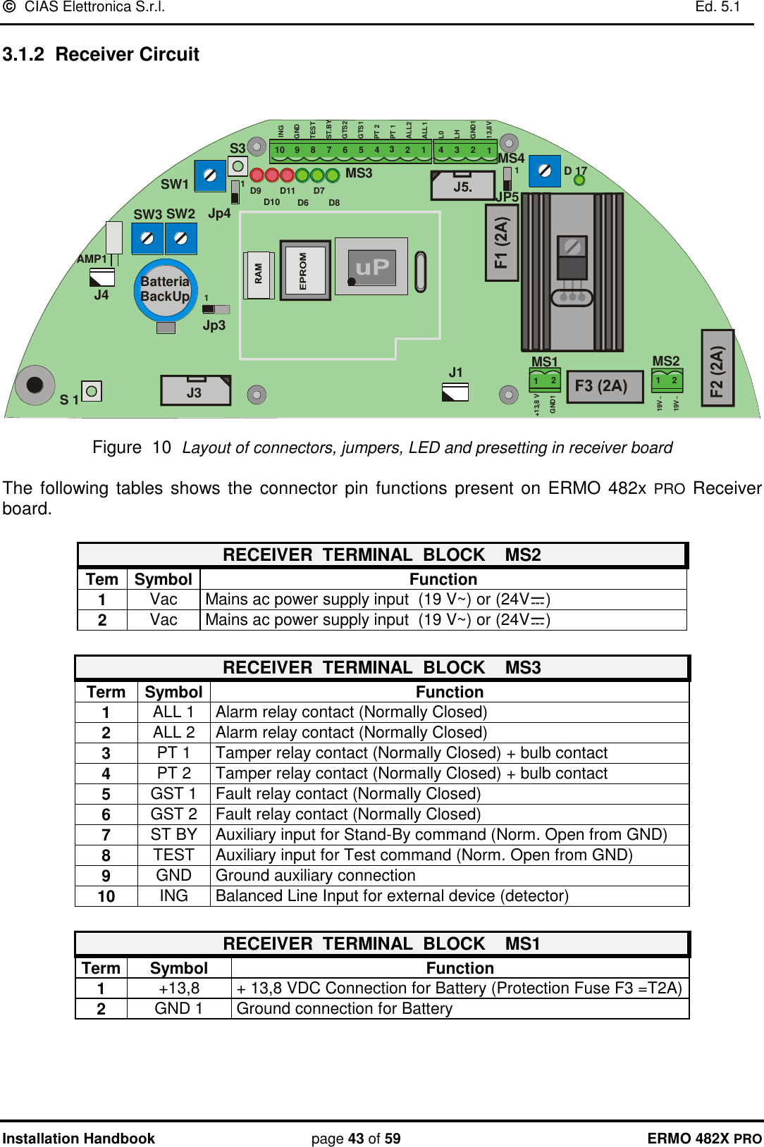
![ CIAS Elettronica S.r.l. Ed. 5.1 Manuale di Installazione Pagina 10 di 59 ERMO 482X PRO 2030104050607080901002030104050607080901002.5 5 7.5 10 12.5 15 17.5 20 22.5 25Altezza dal suoloal centroantenna [cm]SensibilitàMassimaLunghezzazona morta [m]Sensibilitàminima Figura 8 Lunghezza della zona morta in prossimità degli apparati in funzione dell’altezza dal centro degli stessi al suolo per ERMO 482x PRO / 250-500 F5 5 M80-85 cm Figura 9 - Sovrapposizione di due fasci sensibili in un incrocio-](https://usermanual.wiki/CIAS-Elettronica-S-R-L/ERMO-482XPRO-K/User-Guide-1883626-Page-11.png)
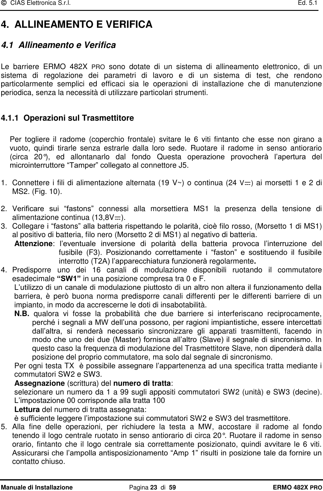
![ CIAS Elettronica S.r.l. Ed. 5.1 Manuale di Installazione Pagina 20 di 59 ERMO 482X PRO Per ciascun rivelatore esterno possono essere gestiti gli stati di: riposo allarme manomissione guasto Possono inoltre essere gestiti gli stati di: taglio Linea di collegamento tra rivelatore e testa (TX o RX) corto Circuito Linea di collegamento tra rivelatore e testa (TX o RX) Per ottenere la gestione di tutti questi stati occorre realizzare una pesatura mediante resistori collegati come nella seguente figura. 0 - 0.5CORTO CIRCUITOSTATODELL’INGRESSOTENSIONE DI INGRESSO[V cc]TAGLIOGUASTOMANOMISSIONEALLARMERIPOSO 0.5 11.51.5 22.52.5 33.53.5 44.54.5 - 5Min. Med. Max. Nella tabella riportata sono indicati i valori di tensione che si localizzano sui morsetti di ingresso della linea bilanciata per i vari stati del rivelatore esterno e della linea che lo collega alla testa TX o RX. Questi valori possono essere letti anche mediante il SW WAVE-TEST nella schermata “Valori Analogici”, sia con un PC collegato localmente che attraverso una connessione remota. AMP1MS1 MS2J2J3J4JP5SW3 SW2SW1S3D 17 S 1J1112 233445678910INGGNDTESTST.BYGTS2GTS1PT 2PT 1ALL2ALL1L0LHGND113,8VGND112+13,8 V1219V~19V~D7D9D6 D8D10D11470 470 1K1,5KRIVELATORE ESTERNOSCHEDA RICEVITOREMS3 MS4](https://usermanual.wiki/CIAS-Elettronica-S-R-L/ERMO-482XPRO-K/User-Guide-1883626-Page-21.png)
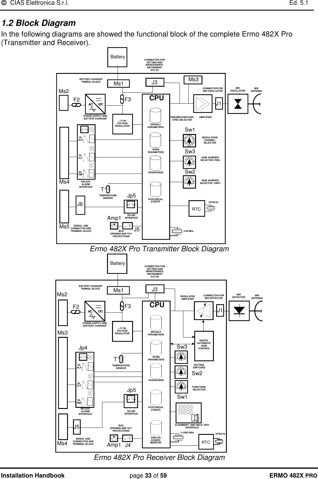
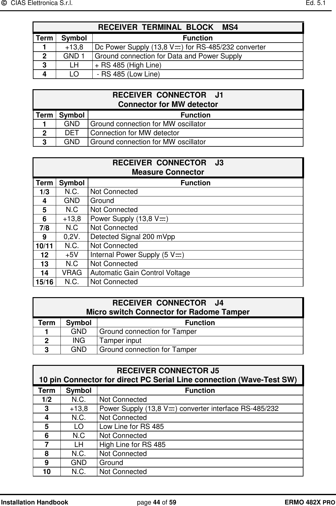
![ CIAS Elettronica S.r.l. Ed. 5.1 Installation Handbook page 36 of 59 ERMO 482X PRO 2.5 Amplitude of the Sensitive Beam The amplitude of the Sensitive Beam depends on the distance between the transmitter and the receiver, on the antenna type and on the sensitivity adjustment set. The figures below state the diameter half-way of the sensitive beam section (based on the length of the section) in case of maximum and minimum sensitivity (see next figures ). 12345678910510 15 20 25 30 35 40 45 50Half rangesensitive zonediameter [m]Range [m]MaximumsensitivityMinimumsensitivity Figure 3 Diameter of sensitive beam at the half-section length (ERMO 482x PRO/ 50) 20 40 60 80 100 120 140 160 180 2002468101214161820 Half rangesensitive zonediameter [m]Range [m]MaximumsensitivityMinimumsensitivity Figure 4 Diameter of sensitive beam at the half-section length (ERMO 482x PRO/ 80-120-200)](https://usermanual.wiki/CIAS-Elettronica-S-R-L/ERMO-482XPRO-K/User-Guide-1883626-Page-37.png)
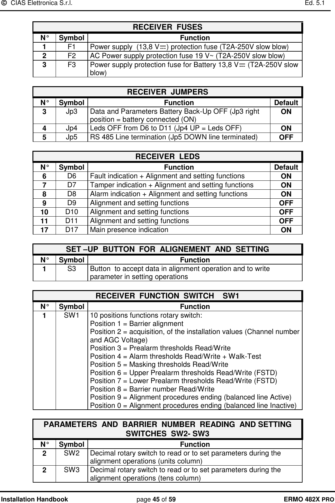
![ CIAS Elettronica S.r.l. Ed. 5.1 Installation Handbook page 37 of 59 ERMO 482X PRO 51015202550 100 150 200 250 300 350 400 450 500Half rangesensitive zonediameter [m]Range [m]MaximumsensitivityMinimumsensitivity Figure 5 Diameter of sensitive beam at the half-section length (ERMO 482x PRO/ 250-500 F5) Remark: that for the ERMO 482x PRO equipment, the sensitivity regulation to be considered to obtaining the dimensions of the sensitivity beam at half- section length, is that of the pre-alarm threshold. The higher the pre-alarm threshold the lower the sensitivity, and vice versa. It’s important to keep in mind that the pre-alarm threshold determines the beginning of the intelligent analysis: all signals below this threshold, are considered noise, and anyway of low importance. All the signals higher this threshold are analyzed following Fuzzy rules. The prealarm and alarm thresholds, are settable both with software WAVE-TEST and with rotary switches on board on each receiver. Default setting corresponds to a medium sensitivity fightable for most of the cases.](https://usermanual.wiki/CIAS-Elettronica-S-R-L/ERMO-482XPRO-K/User-Guide-1883626-Page-38.png)
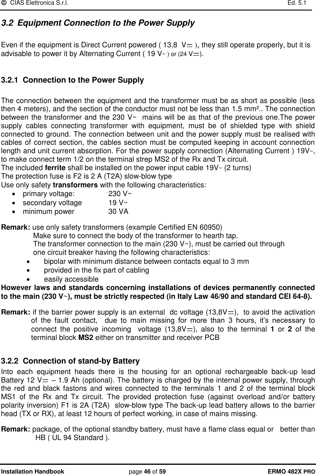
![ CIAS Elettronica S.r.l. Ed. 5.1 Installation Handbook page 38 of 59 ERMO 482X PRO 2.6 Length of the Dead Zones near the equipment The length of the Dead Zones near the equipment is based on the distance of the equipment from ground, on the sensitivity set on the receiver and on the type of antenna used. With regard to the considerations stated above, and based on plant requirements, the equipment must be installed at a certain height from ground. In mean plant the height must be 80 cm. from the ground and the centre of the equipment (90cm for 50-250-500m barriers). With medium sensitivity setting, the suggested crossing overlap is 5m., for the 80-120-200m. 12,5m for 250-500m barriers versions and 3,5m. for the 50m. version. 203010405060708090100203010405060708090100123 4 5 67 8 9 10Antenna centreheight fromground [cm]Dead Zonelenght [m]Maximumsensitivity Minimumsensitivity Figure 6 ERMO 482x PRO-50: Dead zone length near the equipment versus installation height. 203010405060708090100203010405060708090100123 4 5 67 8 9 10Antenna centreheight fromground [cm]Dead Zonelenght [m]Maximumsensitivity Minimumsensitivity Figure 7 ERMO 482 X PRO. 80-120-200: Dead zone length near the equipment versus installation height.](https://usermanual.wiki/CIAS-Elettronica-S-R-L/ERMO-482XPRO-K/User-Guide-1883626-Page-39.png)
![ CIAS Elettronica S.r.l. Ed. 5.1 Installation Handbook page 39 of 59 ERMO 482X PRO 2030104050607080901002030104050607080901002.5 5 7.5 10 12.5 15 17.5 20 22.5 25Antenna centreheight fromground [cm]Dead Zonelenght [m]Maximumsensitivity Minimumsensitivity Figure 8 ERMO 482 X PRO. 250-500 F5: Dead zone length near the equipment versus installation height. 5 M80-85 cm Dead ZoneDead Zone](https://usermanual.wiki/CIAS-Elettronica-S-R-L/ERMO-482XPRO-K/User-Guide-1883626-Page-40.png)
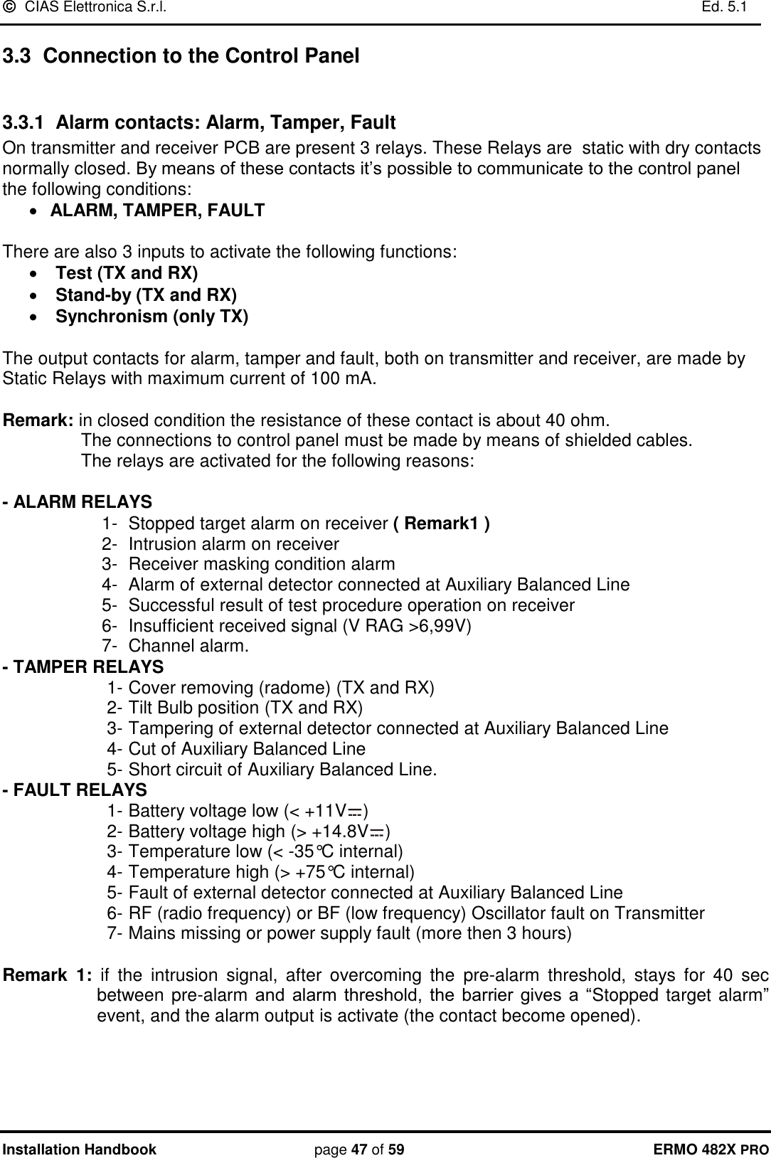
![ CIAS Elettronica S.r.l. Ed. 5.1 Installation Handbook page 49 of 59 ERMO 482X PRO In addition it’s possible to manage the following conditions: Line cut condition of the wires connecting the external detector at TX or RX PCB Short Circuit condition of the wires connecting the external detector at TX or RX PCB To manage all these conditions it’s necessary to use weighting resistors connected like that showed in the following picture. RECEIVER PCBAMP1MS1 MS2J2J3J4JP5SW3 SW2SW1S3D 17 S 1J1112 233445678910INGGNDTESTST.BYGTS2GTS1PT 2PT 1ALL2ALL1L0LHGND113,8VGND112+13,8 V1219V~19V~D7D9D6 D8D10D11MS3 MS4470 470 1K1,5KEXTERNAL DETECTOR In the following table are indicated the voltage values present at balanced inputs for the possible, detector and line, conditions. It is possible to read this values, also by means of WAVE TEST SW in the “Analogue values” window. (PC in local or remote connection) 0 - 0.5LINE SHORT CIRCUITCONDITIONS INPUT VOLTAGE[V dc]LINE CUTFAULTTAMPERALARMREST 0.5 11.51.5 22.52.5 33.53.5 44.54.5 - 5Min. Average Max.](https://usermanual.wiki/CIAS-Elettronica-S-R-L/ERMO-482XPRO-K/User-Guide-1883626-Page-50.png)