CIK Telecom HG-A800 ADSL HOME GATEWAY User Manual HG A800 v1 5 Manual v1 0 0719
CIK Telecom INC. ADSL HOME GATEWAY HG A800 v1 5 Manual v1 0 0719
User Manual
HG‐A800HomeGateway
InstallationandUserManual
Version1–July2012

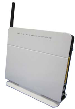
ADSL WiFi Home Gateway
2
Document Control
DateDoc
Version
Change
July17,201211streleaseofdocument
Notices
Emergency Calls
This terminal operates using mobile signals, which cannot guarantee connection in all
conditions. Therefore, you should never rely solely on the terminal equipment for essential
communications such as medical or emergency services.
Temperature
Operating temperature: 0~+50℃
Storage temperature: -40~+85℃

ADSL WiFi Home Gateway
3
Catalog
1.Overview ........................................................................................................................................................... 5
2.Specification...................................................................................................................................................... 5
2.1Features and Technical Specifications............................................................................................... 5
2.2Interface Introduction ........................................................................................................................ 7
2.2.1Indicators & Interface................................................................................................................ 7
2.2.2Package Contents....................................................................................................................... 8
2.2.3Connection Topological Diagram.............................................................................................. 9
2.3Hardware Connection........................................................................................................................ 9
3.Configuration Guide.......................................................................................................................................... 1
3.1Default Configuration........................................................................................................................ 1
3.2Customer Configuration .................................................................................................................... 1
3.2.1Log In and HG-A800 status.......................................................................................................2
3.2.1.1.Login.................................................................................................................................. 2
3.2.1.2.HG‐A800status .................................................................................................................. 3
3.2.2Network ..................................................................................................................................... 5
3.2.2.1.WANservice ....................................................................................................................... 5
3.2.2.2.DSLSettings ....................................................................................................................... 9
3.2.2.3.DMZhost ........................................................................................................................... 9
3.2.2.4.VirtualServer ................................................................................................................... 10
3.2.2.5.StaticRoute...................................................................................................................... 11
3.2.2.6.RIPconfiguration ............................................................................................................. 11
3.2.2.7.QoSconfiguration ............................................................................................................ 12
3.2.3Application .............................................................................................................................. 16
3.2.3.1.UPnPSettings................................................................................................................... 16
3.2.3.2.DynamicDNS ................................................................................................................... 16
3.2.3.3.SambaUsers .................................................................................................................... 17
3.2.4WLAN Configuration.............................................................................................................. 20
3.2.4.1.WLANbasicsetting .......................................................................................................... 20
3.2.4.2.WLANsecurity.................................................................................................................. 20
3.2.4.3.WLANadvancesettings.................................................................................................... 20
3.2.4.4.WLANMACfilters ............................................................................................................ 22
3.2.4.5.WLANBridge .................................................................................................................... 23
3.2.5LAN Configuration.................................................................................................................. 23
3.2.5.1.ConfigurationoftheHG‐A800’sIPaddress...................................................................... 23
3.2.5.2.DHCPConfiguration ......................................................................................................... 24
3.2.6Firewall.................................................................................................................................... 24
3.2.6.1.FirewallSettings............................................................................................................... 25
3.2.6.2.IPFilters ........................................................................................................................... 25
3.2.6.3.DomainFilters.................................................................................................................. 27
3.2.6.4.MACFilters ...................................................................................................................... 29
3.2.6.5.AccessControl(RemoteAccess) ....................................................................................... 29
3.2.7Voice (VoIP)............................................................................................................................. 29

ADSL WiFi Home Gateway
4
3.2.7.1.VoIPBasicSettings ........................................................................................................... 29
3.2.7.2.VoIPAdvancedSettings.................................................................................................... 31
3.2.8Tools ........................................................................................................................................ 32
3.2.8.1.AccountSettings(Users) .................................................................................................. 32
3.2.8.2.TimeSettings ................................................................................................................... 33
3.2.8.3.Diagnostics....................................................................................................................... 33
3.2.8.4.BackupSettings................................................................................................................ 34
3.2.8.5.Update(Restore)Settings ................................................................................................ 35
3.2.8.6.UpdateSoftware.............................................................................................................. 35
3.2.8.7.FactorySettings ............................................................................................................... 35
3.2.8.8.RebootRouter.................................................................................................................. 36
3.2.8.9.SystemLog ....................................................................................................................... 36
3.2.8.10.TR‐069Client.................................................................................................................. 36
3.2.8.11.SNMP ............................................................................................................................. 37
3.2.8.12.PINGReboot .................................................................................................................. 37
4.Troubleshooting............................................................................................................................................... 38
4.1Unable to Access Internet................................................................................................................ 38
4.1.1Check the Line and the Device................................................................................................ 38
4.1.2Check Your Configuration....................................................................................................... 38

ADSL WiFi Home Gateway
5
1. Overview
The HG-A800 V1.5 is an All-In-One wireless VoIP router. It includes the following
main functions:
ADSL2/2+ modem for broadband connection;
Four 10M/100M auto-sensing Ethernet ports for wire connection;
Build-in 802.11n enhanced WLAN complies with IEEE 802.11n draft v2.0 and
backward to 802.11b/g specifications. It supports 2x2 MIMO and up to
300Mbps of rate bandwidth. The throughput of WLAN to LAN is more than
100Mbps;
Supports 1 USB 2.0 host port for Printer and USB storage or 3G dongle
application;
One FXS port for VoIP call;
Supports TR-069 remote management;
2. Specification
2.1 Features and Technical Specifications
DSLStandards
z ANSI T1.413 issue 2compliant
z ITU-T G.992.1 (G.DMT) compliant
z ITU-T G.992 (G.lite) compliant
z ITU-T G.992.3/4 (ADSL2) compliant
z ITU-T G.992.5 (ADSL2+) along with Annex A and M
Configurations
z Payload Encapsulation
z RFC 2516, PPPoE (PPP over Ethernet)
z RFC 2364, PPPoA (PPP over AAL5)
z RFC 2684, Bridge
z RFC 2684 Routed
z Support 8 PVCs
z Support Port Mapping
IP
z NAT/NAPT
z Firewall, support SPI (Stateful Packet Inspection)
z DHCP Server
z Port forwarding (Support DMZ)
z IP filtering, bridge filtering, web filtering
z Static routing

ADSL WiFi Home Gateway
6
z Dynamic routing;
z SNTP;
z VPN, support IPSec/PPTP/L2TP;
z Multicast: IGMP Proxy/Snooping;
z ALG;
Ethernet
z IEEE 802.3;
z 4 port Ethernet: 10/100M Ethernet Auto MDI-X;
Wi‐Fi
z IEEE 802.11 b/g/n compliance;
z Security: WEP 64/124/256 bits, WPA/WPA2;
z WMM QoS;
z WDS wireless AP;
z RF power: 20dBm;
z Transmission Power:
802.11b: 17+/-1.5dBm;
802.11g: 14+/-1.5dBm;
802.11n: HT20 14+/-1.5dBm; HT40 12+/-1.5dBm;
z Reception Sensibility:
802.11b: -82dBm, ±2dB;
802.11g: -68dBm, ±2dB;
802.11n: HT20 -64dBm, ±2dB; HT40 -60dBm, ±2dB;
z Spurious emission/harmonics: -50dBc;
z Antenna:
2T2R MIMO mode (2 transmitter, 2 receiver);
One external antenna with 2dBi gain; One internal antenna with 4dBi gain;
Operating Temp: -10~+60℃;
z RF on/off;
z ACS(Automatic channel selection);
z MAC address white-black filter;
OperationandManagement(OAM)
z Support Web based management;
z UPnP;
z Telnet/SSH;
z Software upgrade through HTTP/TFTP/FTP;
z TR069 (CPE management through WAN interface);
z SNMP agent and tools;
QoS
z IP QoS: base on source IP address, source and destination port, protocol and DSCP;
z ATM QoS: support CBR, UBR, nrt-VBR, rt-VBR;
ADSL WiFi Home Gateway
7
z QoS features including support for extended Impulse Noise Protection (INP) for better
IPTV quality;
VoIP
z Support SIP or MGCP protocols;
z Support one analog phone;
z Flexible dial plan customization;
z Support multiple CODECs, including G.711, G.729 and so on;
z Supports DTMF tone detection and generation;
z Support Echo Cancellation, Silence suppression, Comfort Noise Generation and Voice
Activity Detection(VAD);
z SIP Call Forwarding;
z T.38 Fax Relay;
Temperature
z Operating temperature: 0~+50℃
z Storage temperature: -40~+85℃
2.2 Interface Introduction
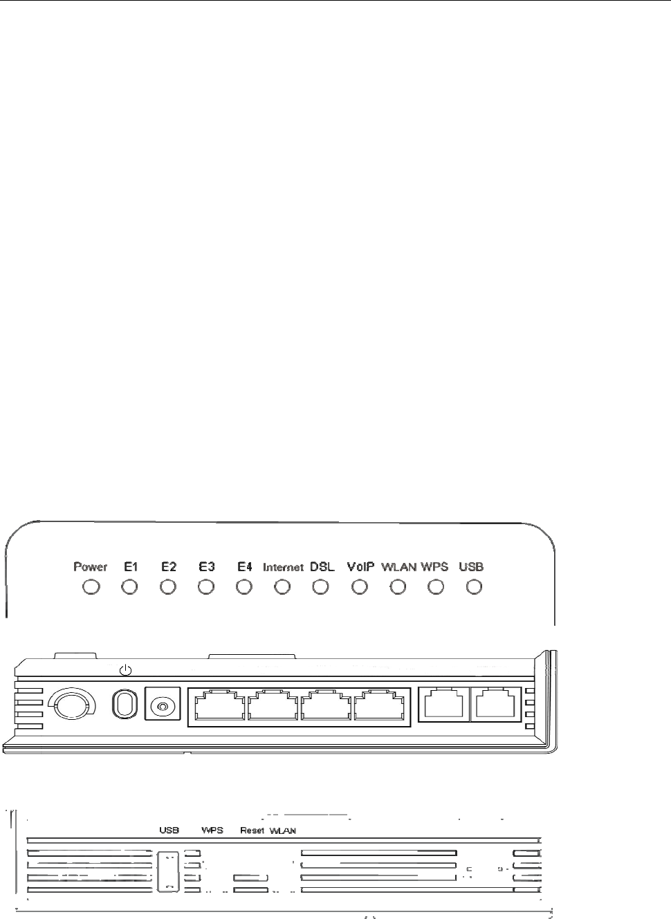
2.2.1 Indicators & Interface
Indicators:
Interface 1:
Interface 2:
Power E1 E2 E3 E4 VoIP DSL

ADSL WiFi Home Gateway
8
Item Label Description
On: Modem power up
Power Off: Modem Power off
On: Ethernet is connected
Blinking green: Ethernet Traffic flows
E1-E4 Off: Ethernet is disconnected
Blinking green: PPP/DHCP negotiation
Solid green: PPP/DHCP up
Internet Quick blinking green: Tx/Rx traffic on line
On: Modem synchronized to the DSLAM
Quick blinking green: Modem training, but not synchronized
DSL Slow blinking green: Modem Idle
On: The analog phone connected to VoIP off-hook
VoIP Off: The analog phone connected to VoIP on-hook
On: WLAN connection is available
Blinking green: Negotiation or traffic on line
WLAN Off: WLAN connection is not available
ON:WLAN connection is setup
Blinking green: connecting WLAN
WPS Off: WLAN connection is fail
On: recognize the USB device
Blinking green: USB data traffic
Indicators
USB Off: un-plug or un-recognized USB device
Power switch
Power For 12V DC power adapter
E1-E4 LAN interface for connecting to computers
VoIP Connecting to analog telephones
Interface 1
DSL Connecting to ADSL enabled telephone line
USB USB 2.0 host for Printer and USB storage or 3G dongle application
WPS WPS switch
Reset Restore to factory default settings
WLAN WLAN switch
Interface 2
WLAN antenna
2.2.2 Package Contents
Item Quantity
Power Adapter 1
Phone Line 2
RJ-45 Cable 1
Modem 1
Splitter 1
ADSL WiFi Home Gateway
9
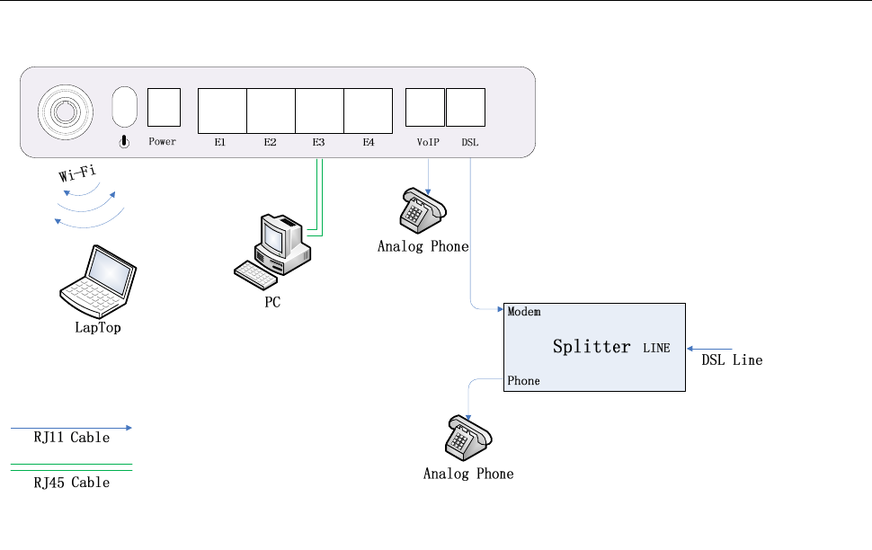
2.2.3 Connection Topological Diagram
2.3 Hardware Connection
1. Use a telephone cord to connect the LINE port of the splitter with the phone socket on the
wall (only if using ADSL).
2. Use another telephone cord to connect the ADSL port of the splitter with the DSL port of
the HG-A800 (only is using ADSL).
3. Connect Ethernet port of the HG-A800 with 10/100BASE-T port of the computer using the
network cable that comes with the unit.
4. Plug in the power cord, and turn on the power.
3. Configuration Guide
3.1 Default Configuration
The HG-A800 is pre-configured with the common VCI/VPI settings. The default dial-up
mode is bridge encapsulation. For bridge mode, there is no need to configure any more
parameters. However, the third party dial-up software is needed for connection with the
Internet.
3.2 Customer Configuration
The default IP address for HG-A800 is: 192.168.1.1; The Subnet Mask is:255.255.255.0.
Users can configure the HG-A800 through a web browser. The HG-A800 can be used as a
gateway and DNS server; users need to set the computer’s TCP/IP protocol as follow:
1. Set the computer IP address to the same subnet as the HG-A800 i.e. set the IP address
of the PC to one in the range of 192.168.1.2 - 192.168.1.254 excluding 192.168.1.1.
2. Set the computer’s gateway address to the IP address of the HG-A800.
3. Set the computer’s Primary DNS server to the IP address of the HG-A800 or to that of an
effective DNS server.
3.2.1 Log In and HG-A800 status
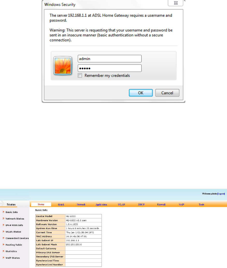
3.2.1.1. Login
Power on to start the device, then make sure your computer can PING the HG-A800 (the
factory default IP is 192.168.1.1), then run the web browser. Enter http://192.168.1.1 in
the address bar, press ENTER, and the authentication interface will pop up as below:
The default user name and password is admin for web log-on. Press ENTER or click on
‘OK’ to enter the configuration interface.
Warning: Please be sure the IP of the computer network card is in the same IP range as
the HG-A800 LAN port before trying to log on (ex: 192.168.1.2 and 192.168.1.1 are in the
same IP range). If the login is not displayed please check in Internet
Explorer--Tools---Internet Options---Connection---LAN Setup---Proxy server, disable the
function ‘Proxy for LAN’ and then retry.
If log on successfully, the main page will be displayed as follows:
3.2.1.2. HG‐A800status
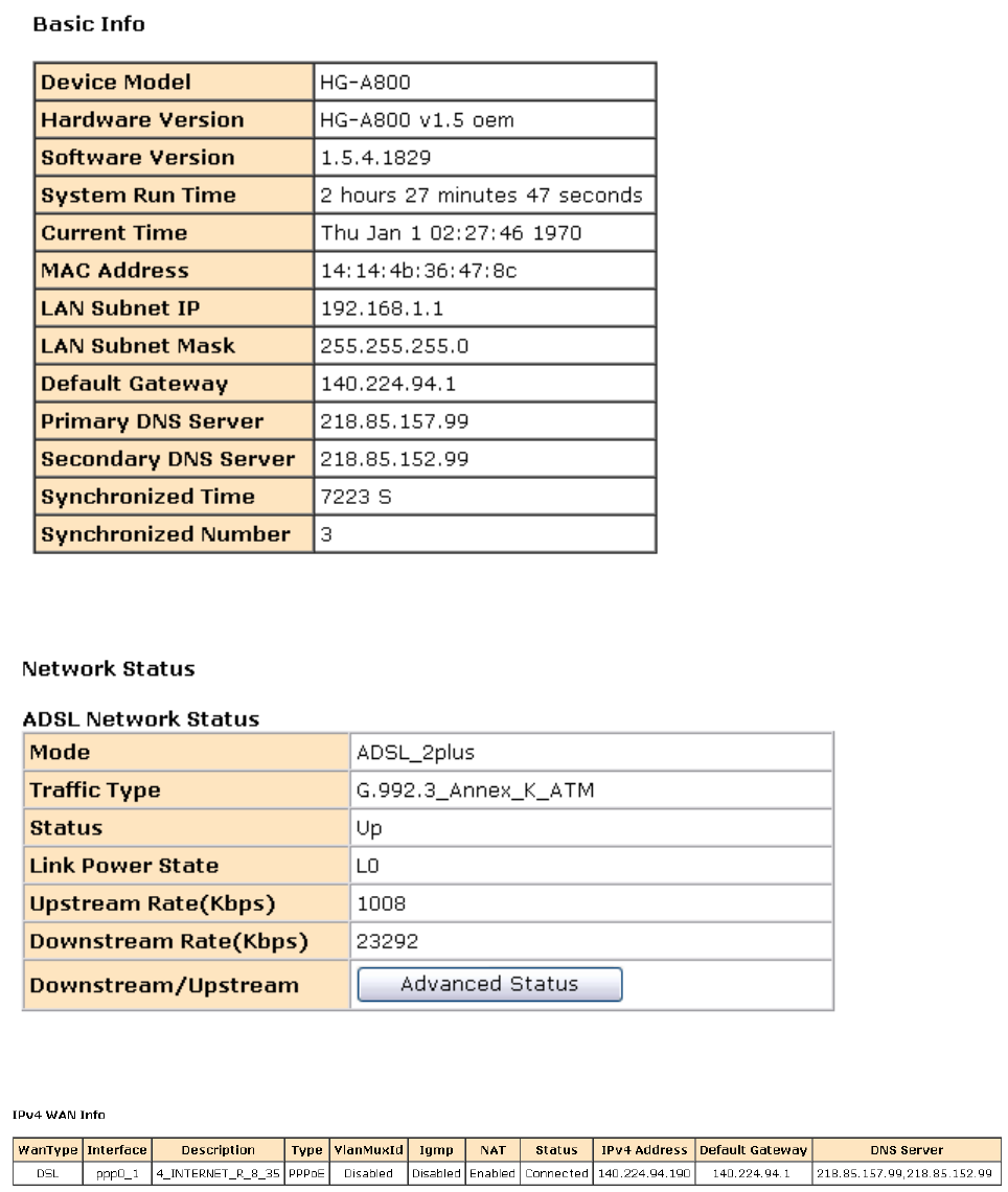
【Status】→【Basic Info】to show device information:
【Status】→【Network Status】to show DSL information:
【Status】→【IPv4 WAN Info】to show information of WAN connection:
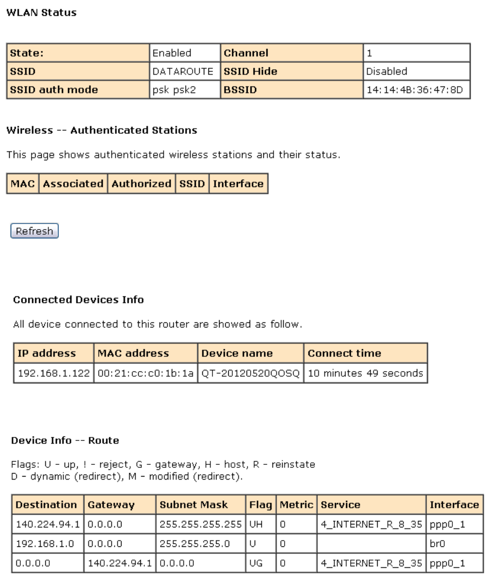
【Status】→【WLAN Status】
【Status】→【Connected Devices Info】
【Status】→【Routing Table】
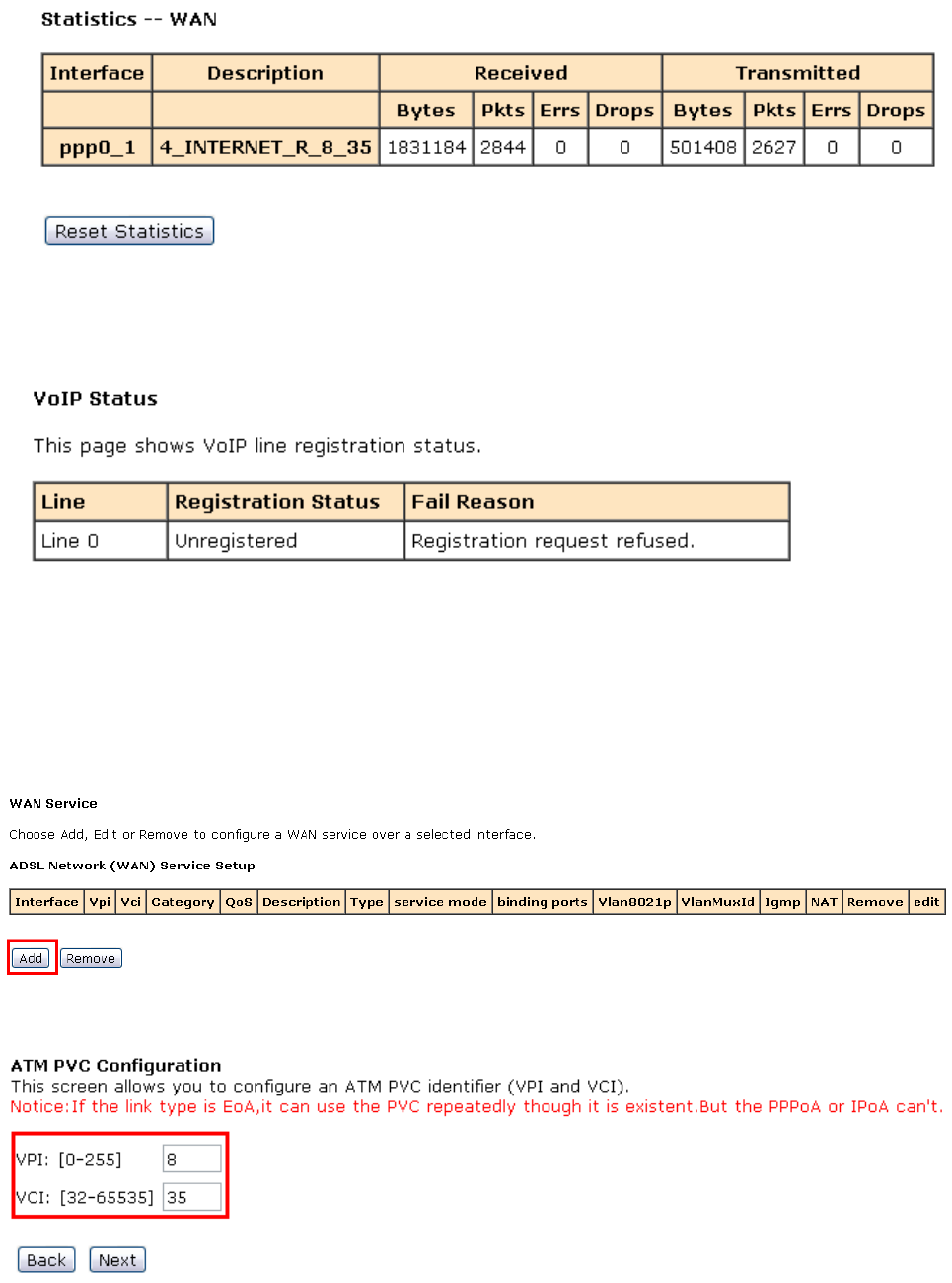
【Status】→【Statistics】
【Status】→【VoIP Status】
3.2.2 Network
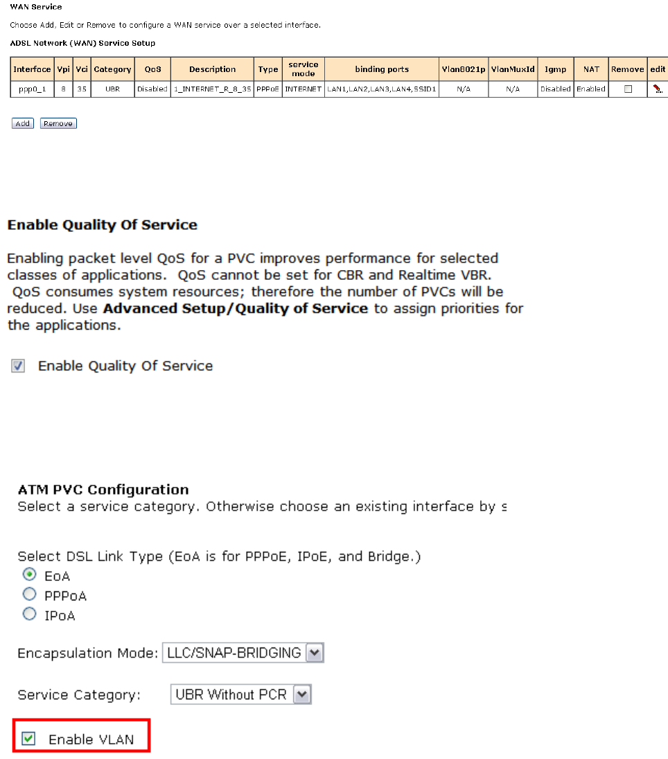
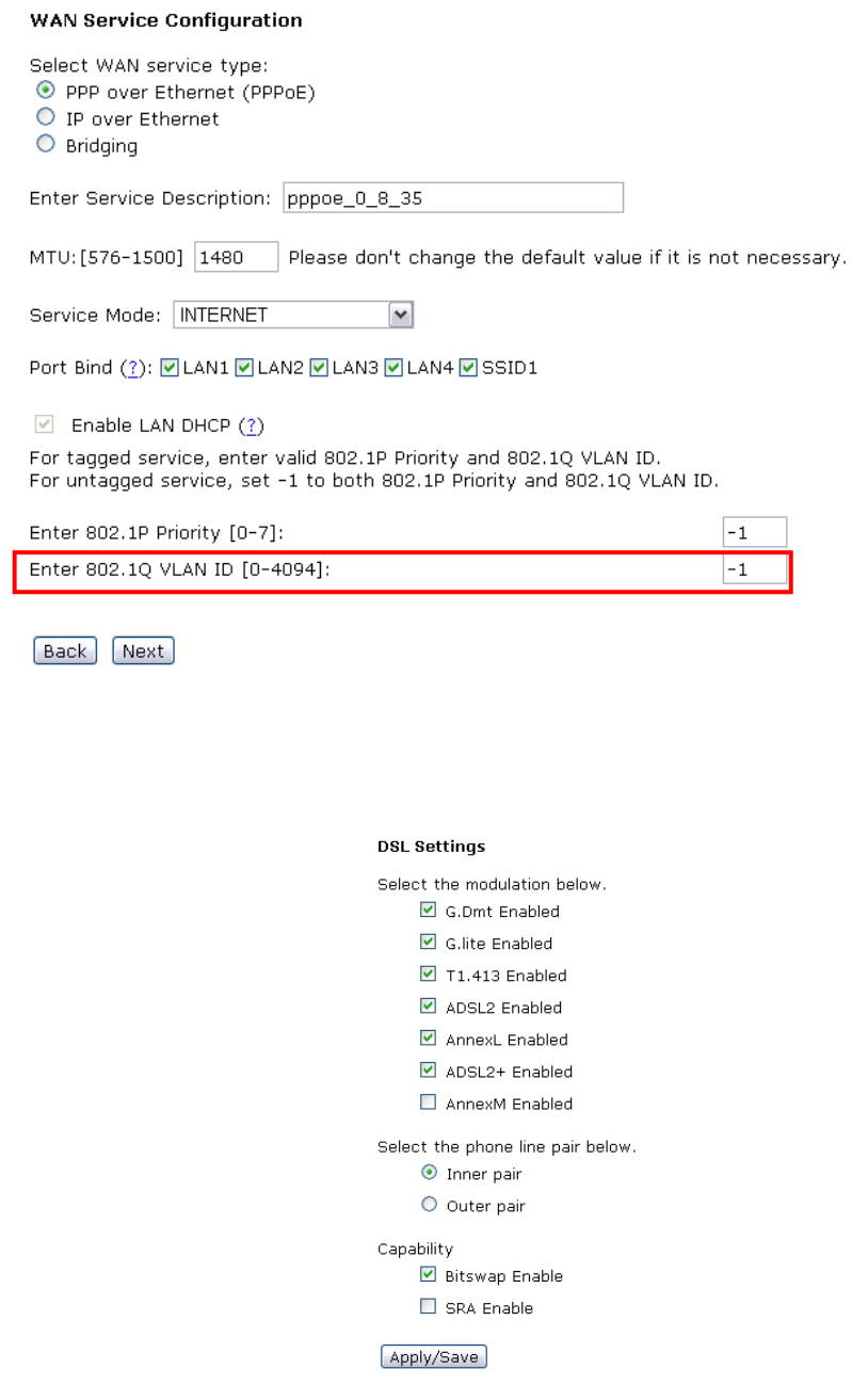
3.2.2.1. WANservice
Please go to 【Network】→【WAN Service】page.
1) Click Add button to configure an ATM PVC identifier;
2) Click Next to select a service category; (here please choose EoA for PPPoE connection)
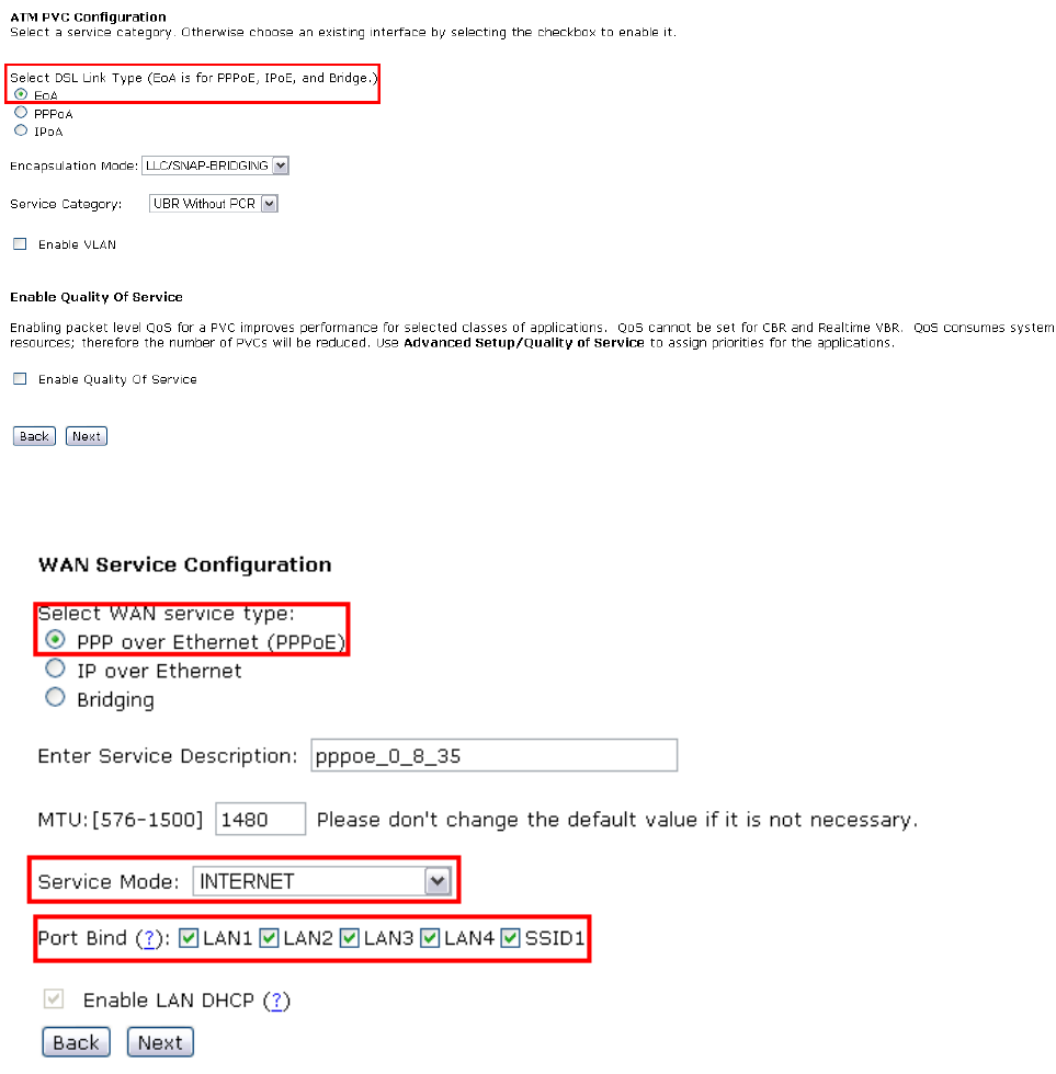
3) Click Next to select WAN service type; (here please choose PPP over Ethernet)
4) Click Next to input the username and password authorized by your ISP; (here please
make Enable NAT checked)
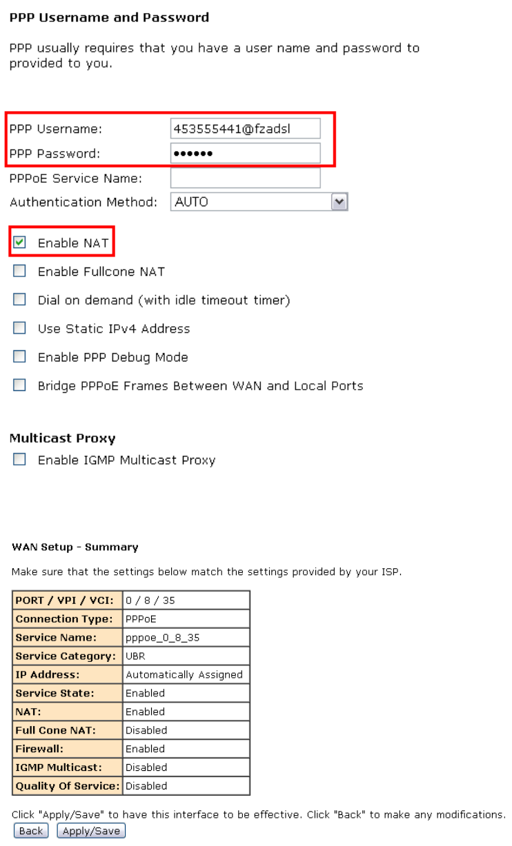
5) Click Next to check the Summary of this connection;
6) Click Apply/Save to enable the connection.
Note : if you need the Quality of service, pls enable QoS in WAN service config, then go
to 【Network】→【Qos configuration】for the QoS setting.
Note : if you need the VLAN channel, please “Enable VLAN” and set VLAN id in WAN
service config:
3.2.2.2. DSLSettings
【Network】→【DSLSettings】
3.2.2.3. DMZhost
The DSL router will forward IP packets from the WAN that do not belong to any of the
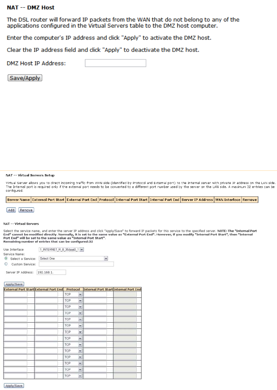
applications configured in the Virtual Servers table to the DMZ host computer.
3.2.2.4. VirtualServer
Virtual Server allows you to direct incoming traffic from WAN side (identified by Protocol and
External port) to the Internal server with private IP address on the LAN side. The Internal
port is required only if the external port needs to be converted to a different port number
used by the server on the LAN side.
【Network】→【 Virtual Servers Setup】Æ click ADD
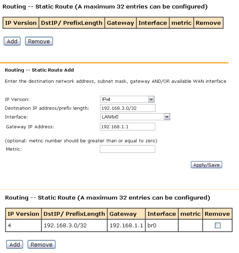
3.2.2.5. StaticRoute
The user can edit the static route table for connecting different network.
1) 【Network】→【 Static Route】
2) Click ADD to edit the IP version, Destination IP, Gateway IP, etc.
3) Click Apply
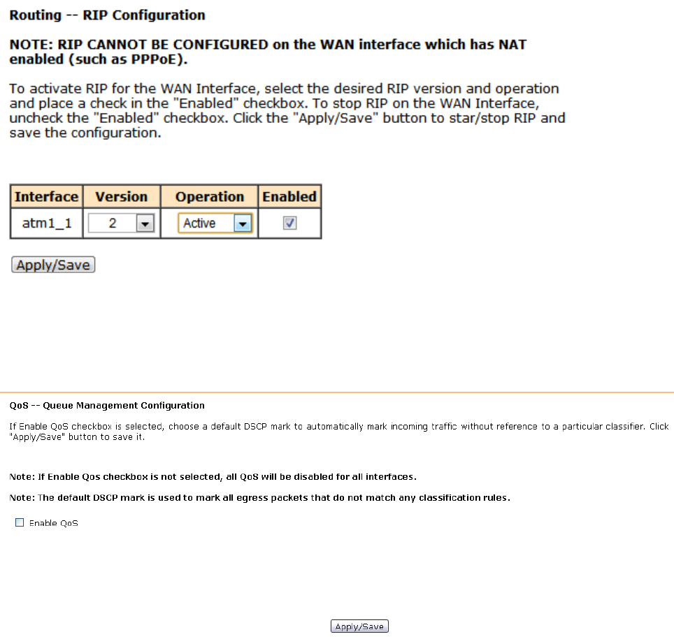
3.2.2.6. RIPconfiguration
RIP will send routing updates information of network layout. When the device receive
updated information, it will update routing table with new path.
【Network】→【RIP Configuration】
3.2.2.7. QoSconfiguration
【Network】→【QoS Configuration】
If Enable QoS checkbox is selected, a default DSCP mark should be chosen to automatically
mark incoming traffic without reference to a particular classifier. Click Apply/Save button to
save.
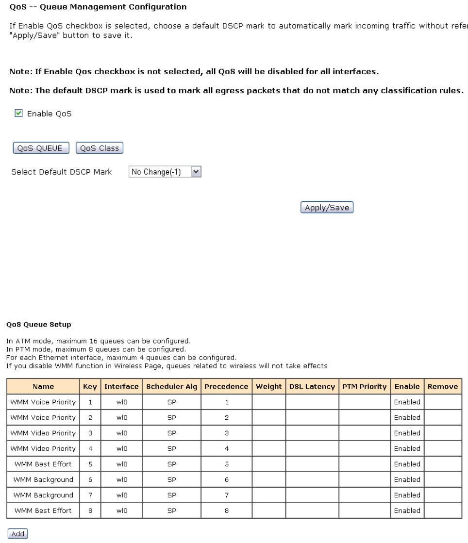
Note: If Enable QoS checkbox is not selected, all QoS will be disabled for all interface; The
default DSCP mark is used to mark all egress packets that do not match any classification
rules.
Please click QoS QUEUE button to enter the QoS Queue setup page,
click Add button. This screen allows you to configure a QoS queue and assign it to a specific
layer 2 interface. The scheduler algorithm is defined by the layer 2 interface, for example:
add Queue Q1 in wan connection(PVC=0/35):
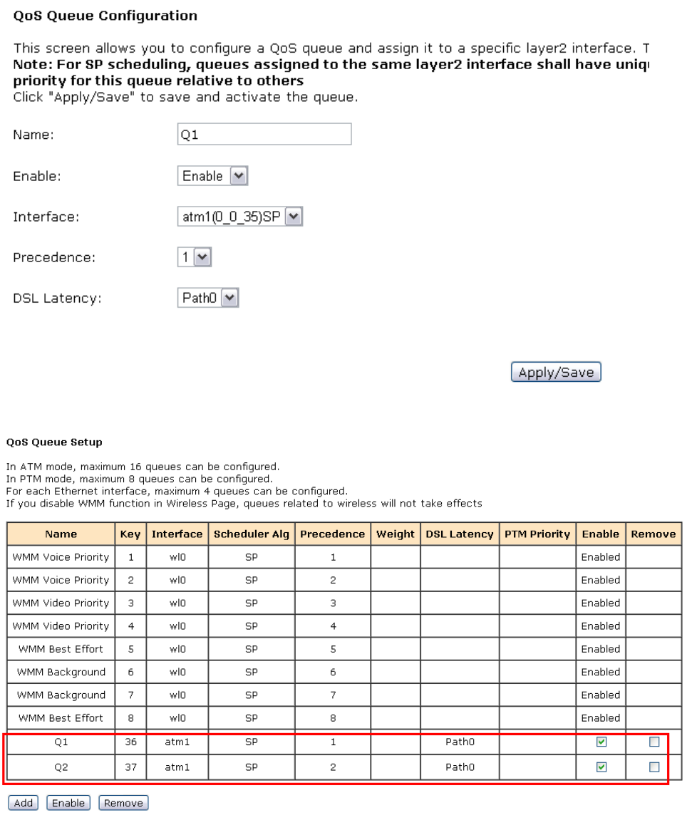
Click Apply/Save to save and activate the queue.
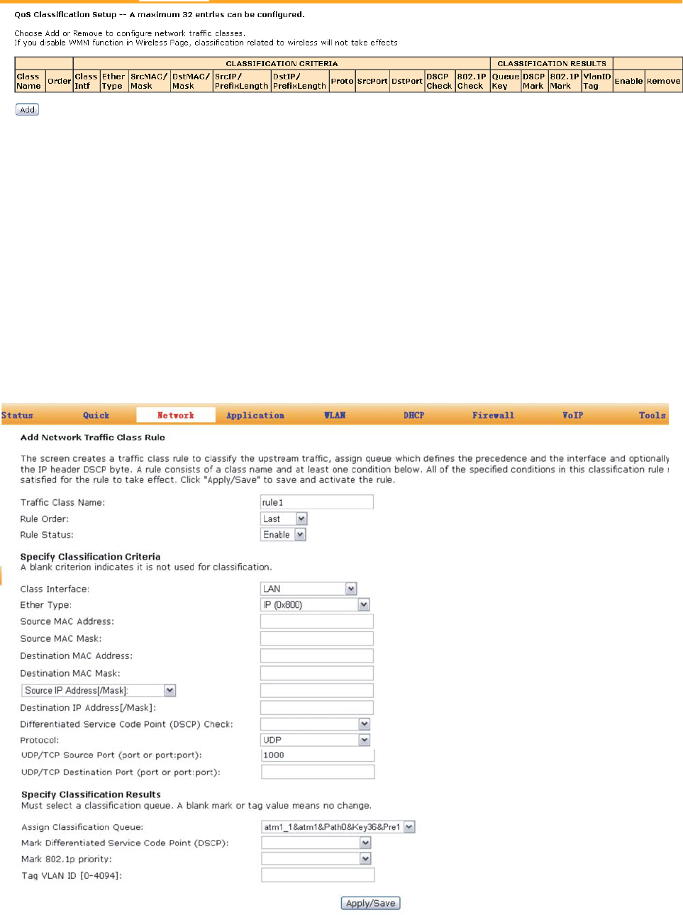
Please click QoS Class button to enter QoS Classification Setup page,
click Add button to configure network traffic classes. This screen creates a traffic class rule
to classify the upstream traffic, assign queue which defines the precedence and the interface
and optionally overwrite the IP header DSCP byte. A rule consists of a class name and at least
one condition. All of the specified conditions in this classification rule must be satisfied for the
rule to take effect. Click Apply/Save to save and activate the rule.
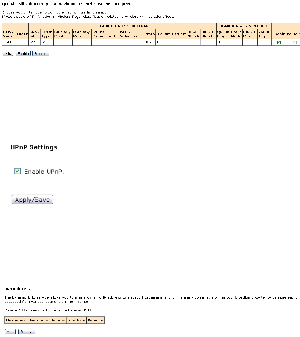
For example: add rule1 to bandage the data from UDP port 1000 to queue Q1:
1. “Traffic Class Name”: rule1
2. “Rule Status”:Enable the class
3. “Ether Type”: IP (0x800)
4. “Protocol”: protocol UDP and Source Port:1000
5. “Assign Classification Queue”to chose Queue Q1:
atm1_1&atm1&Path0&key36&pre1
3.2.3 Application
3.2.3.1. UPnPSettings
Through the UPnP (Universal Plug and Play) of HG-A800, the external PCs are able to access
the resource of the internal PCs connected with the LAN port of HG-A800.
【Application】→【UPnP Settings】
3.2.3.2. DynamicDNS
The Dynamic DNS service allows you to alias a dynamic IP address to a static hostname in
any of the many domains, allowing your Broadband Router to be more easily accessed from
various locations on the Internet.
【Application】→【Dynamic DNS】
Click ADD to add Dynamic DNS, for example:

3.2.3.3. SambaUsers
【Application】→【Samba Users】to add the Samba storage account
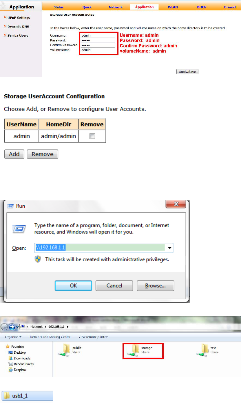
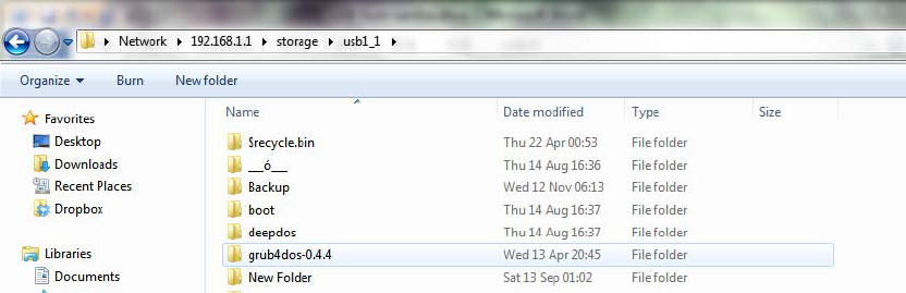
Then you can Visit the USB storage.
For example with Win7 OS, please Run: \\192.168.1.1
Double click storage:
Double click:
The usb disk will be shown:
3.2.4 WLAN Configuration
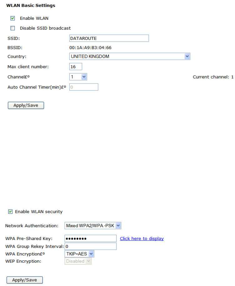
3.2.4.1. WLANbasicsetting
Click WLAN to configure the wireless feature of the modem.
1) Go to path: 【WLAN】->【WLAN Basic】page to enable/disable WLAN feature. Then click
Apply/Save button;
3.2.4.2. WLANsecurity
Go to path: 【WLAN】-> 【WLAN Security】 page to set the network authentication method,
selecting data encryption, specify whether a network key is required to authenticate to
this wireless network and specify the encryption strength. Click Apply/Save when done.
The default Wireless Key is data1234 – it is strongly recommended that this be
changed.
3.2.4.3. WLANadvancesettings
【WLAN】→【Advance Settings】
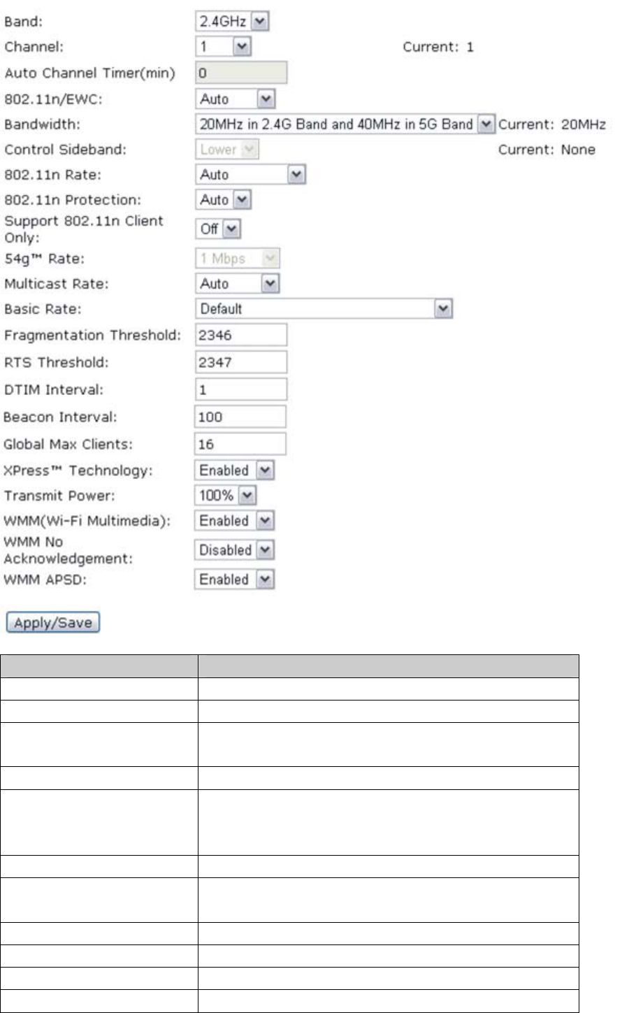
Note:
Item Description
Band Set the band of AP,default value: 2.4GHz
Channel Set the channel of AP, the maximum is 11
Auto Channel
Timer(min) Set the timer for auto-setting the channel
54g™ Rate Set the 54g™ Rate
Multicast Rate Specify a transmission speed for AP. As for the
"Auto", the AP will automatically according to the
environment select a best transmission speed.
Basic Rate Set the basic rate
Fragmentation
Threshold Default value: 2346。
RTS Threshold Default value: 2347。
DTIM Interval specified the DTIM Interval
Beacon Interval Default value: 100ms
Global Max Clients The number of clients can access to AP
XPress™ Technology Enable or disable XPress™
54g™ Mode 54g Auto:Have the greatest compatibility
54g Performance:best performance with 54g
device
54g LRS:solve the problem with 802.11b device
802.11b Only:only for 802.11b device
54g™ Protection When 54g™ protection is enabled, g-mode of 11g
will be auto enabled in 11g data transmission.
Preamble Type Set Preamble Type
Transmit Power Transmit Power with 20%,40%,60%,80%,100%.
WMM(Wi-Fi Multimedia) Set Wi-Fi Multimedia
WMM No Set WMM No
WMM APSD Set WMM APSD
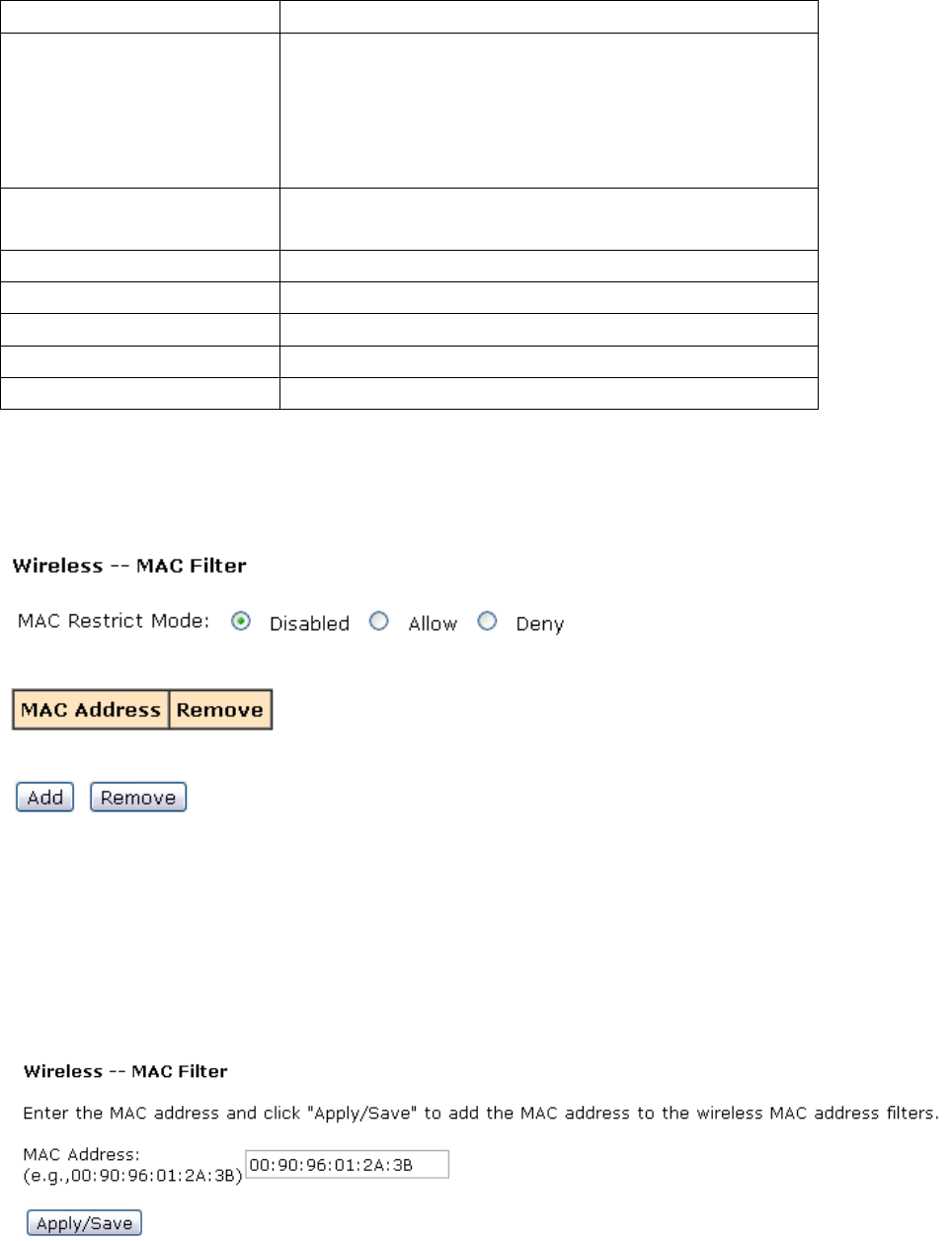
3.2.4.4. WLANMACfilters
【WLAN】→【WLAN MAC Filters】
z Allow:The computer with the matching MAC address in the list of MAC address can
access to Internet.
z Deny:The computer with the matching MAC address in the list of MAC address can
not access to Internet.
For example: The computer with MAC 00:90:96:01:2A:3B can not surf the internet through
HG-A800.
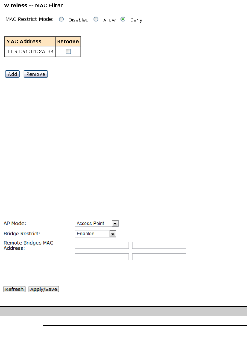
3.2.4.5. WLANBridge
This page allows you to configure wireless bridge features of the wireless LAN interface. You
can select Wireless Bridge (also known as Wireless Distribution System) to disable access
point functionality. Selecting Access Point enables access point functionality. Wireless bridge
functionality will still be available and wireless stations will be able to associate to the AP.
Select Disabled in Bridge Restrict which disables wireless bridge restriction. Any wireless
bridge will be granted access. Selecting Enabled or Enabled(Scan) enables wireless bridge
restriction. Only those bridges selected in Remote Bridges will be granted access.
Click "Refresh" to update the remote bridges. Wait for few seconds to update.
Click "Apply/Save" to configure the wireless bridge options.
【WLAN】→【WLAN Bridge】
Note:
Item description
Wireless Bridge Only support wireless bridge, not for AP AP Mode
Access Point Support all AP and wireless bridge
Enabled No limited to access Bridge
Restrict Disabled Only for specified Remote Bridges MAC Address
Remote Bridges MAC Address
3.2.5 LAN Configuration
3.2.5.1. ConfigurationoftheHG‐A800’sIPaddress
As a network device, ADSL Modem has its own IP address and MAC address. The factory sets
the default IP address of 192.168.1.1 and subnet mask of 255.255.255.0. The user can
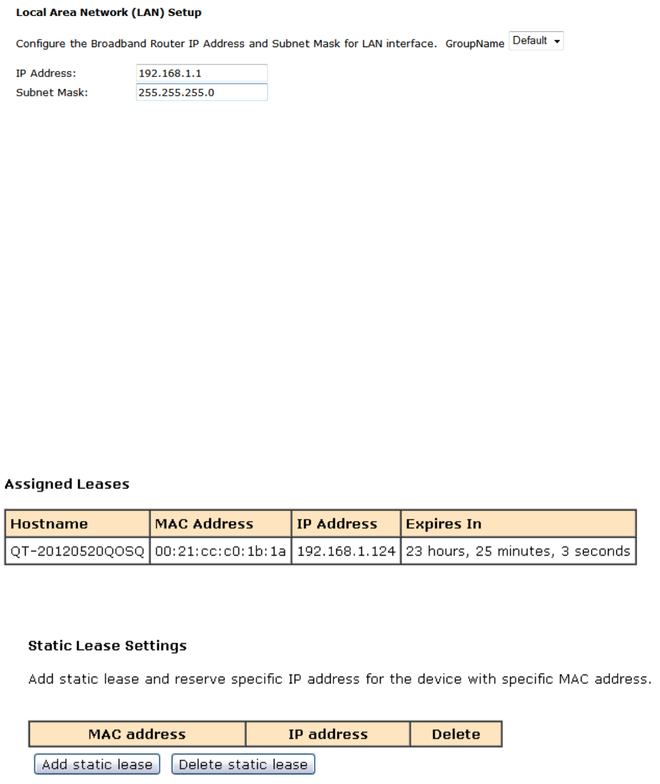
configure these addresses through the Service Settings on DHCP like this:
For example, change IP address to “192.168.1.10”. Click LAN, input IP address:
192.168.1.10, then “subnet mask”: 255.255.255.0, Press “Save” when configuration is
finished.
3.2.5.2. DHCPConfiguration
【DHCP】→【LAN Setup】
1. Click DHCP;
2. Click Service Settings;
3. Define the “Start IP address” and the “End IP address” of DHCP server (for example,
from 192.168.1.11 to 192.168.1.254);
4. Input the value of lease (Measured by the second, 0 indicates permanently valid);
5. Enable DHCP server, computer will set the IP Address of the PC with one of the addresses
192.168.1.2 ~192.168.1.254 (Excluding 192.168.1.1);
Note: When you use the DHCP Server, please make sure you don’t have multiple DHCP
Servers in one LAN.
【DHCP】→【Assigned Leases】to show the assigned IP
【DHCP】→【Static Lease】to assign a special IP address to specified MAC.
3.2.6 Firewall
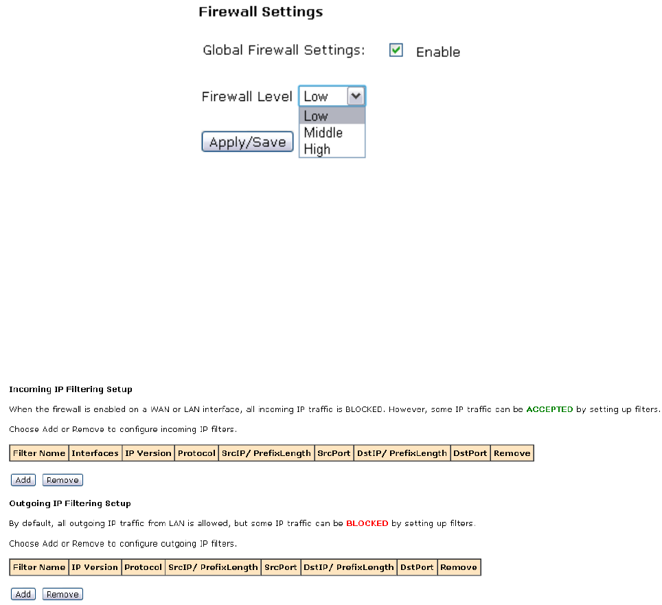
3.2.6.1. FirewallSettings
1) Please go to path:【Firewall】→【Firewall Settings】,open the Firewall settings page;
2) Check “Enable”,and then click “Apply/Save” to activate Global firewall;
Note: three Firewall levels are supported in the device, they are:
z Low: enable basic firewall features - prevent port scanning; allow PING from WAN
side; allow ICMP redirect messages from WAN side.
z Middle: in addition to Low level, prevent ICMP redirect messages.
z High: in addition to Middle level, prevent SYN Flood attack; against PING from WAN
side.
3) Select the level of security you need in the “Firewall Level” list,and then click
“Apply/Save” to save the setting.
4) After configuring, it will display the new firewall status on the page.
3.2.6.2. IPFilters
The IP filters can refuse or allow the communication between LAN computer and the Internet,
can refuse or allow specific IP address’s specific port or all ports, can refuse or allow specific
protocol type.
【Firewall】→【IP Filter】,enter the page of Incoming IP Filtering Setup。
z Inbound filter
1) Click Add button to configure incoming IP filters. The following interface allows user to
create a filter rule to identify incoming IP traffic by specifying a new filter name, protocol,
source port and WAN connection information.
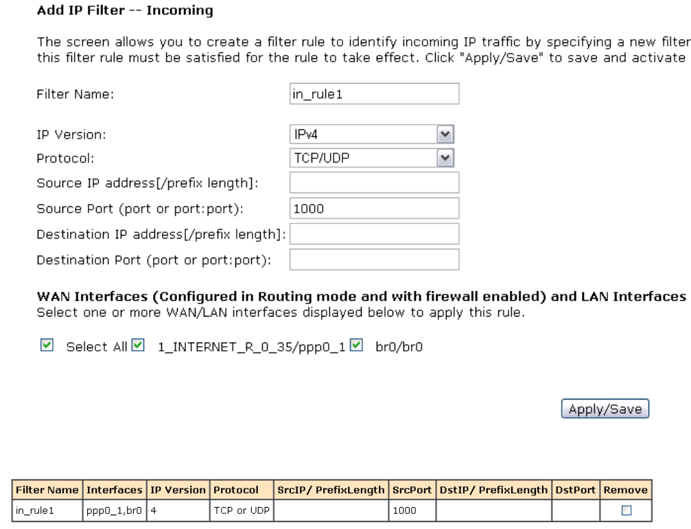
Create a rule like this:only allows the internet data inbound whose protocol is
TCP/UDP and source port is 1000. the filter name is in_rule1:
1. “Filter Name”:in_rule1。
2. “Protocol”: choose “TCP/UDP”;
3. “Source Port (port or port:port)”:1000;
4. select “Select All” to take this rule effect to all the internet connections in the
HG-A800.
2) After entering the required settings click the Apply/Save button.
3) If success, you will see the new added rule in the below figure:
4) If needs to delete the IP inbound filter rule, choose the radio buttons on the right,and
then click the “Remove”.
z Outbound filter
1) Click Add button to configure outgoing IP filters. The following interface allows user to
create a filter rule to identify incoming IP traffic by specifying a new filter name, protocol,
source port and WAN connection information.
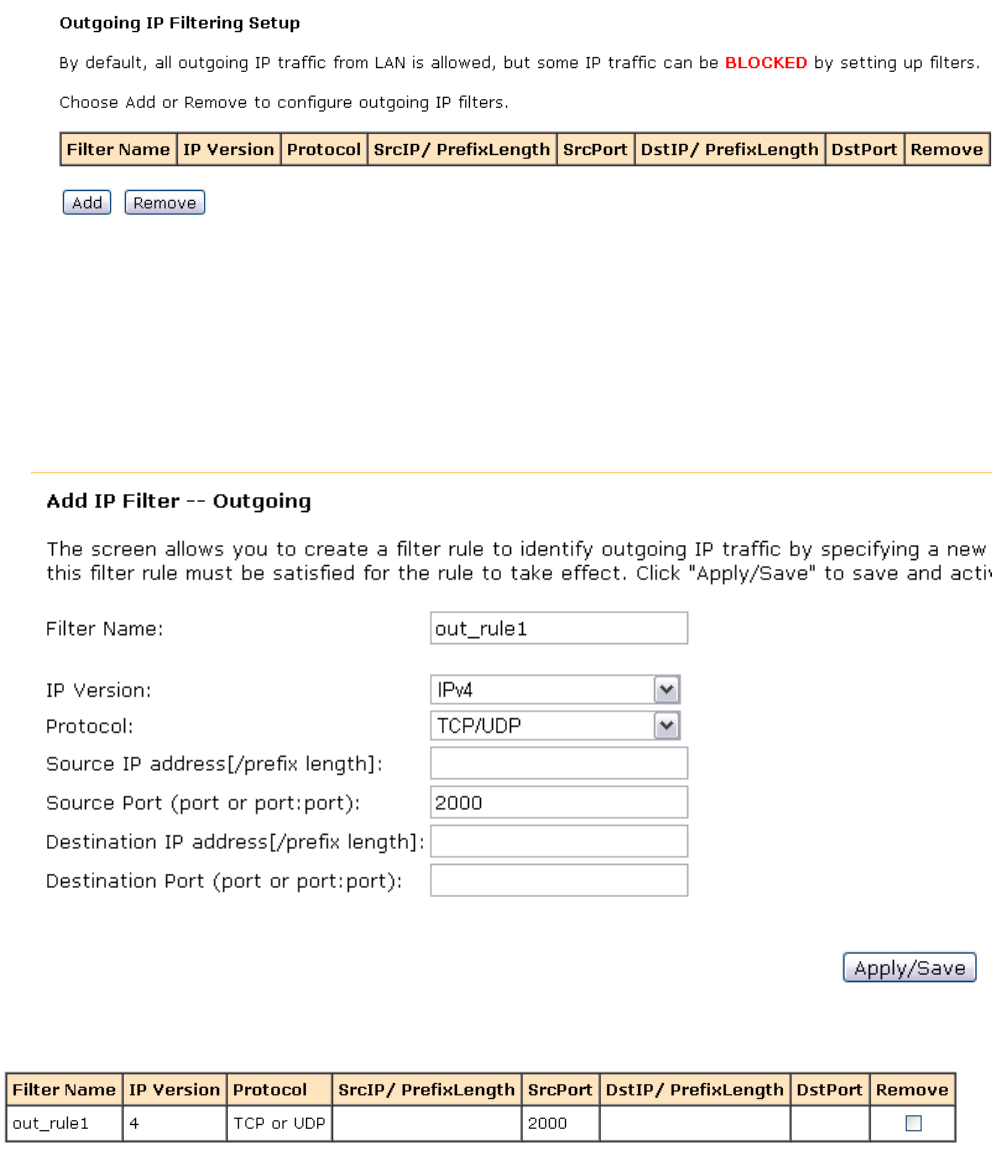
Create a rule like this:Do not allow the LAN data outbound whose protocol is TCP/UDP
and source port is 2000, the filter name is out_rule1, specific settings:
1. “Filter Name”:out_rule1;
2. “Protocol”: choose “TCP/UDP”;
3. “Source Port (port or port:port)”:2000。
2) After entering the required settings click the Apply/Save button;
3) If success, you will see the new added rule in the below figure:
4) If needs to delete the IP outbound filter rule, choose the radio buttons on the right, and
then click the “Remove”
3.2.6.3. DomainFilters
The Domain filter can prevent all the LAN computers from accessing the specific WAN domain
name; this feature will refuse all the requests to the specific domain name.
Please go to path:【Firewall】→【Domain Filter】page. Please select the list type first then
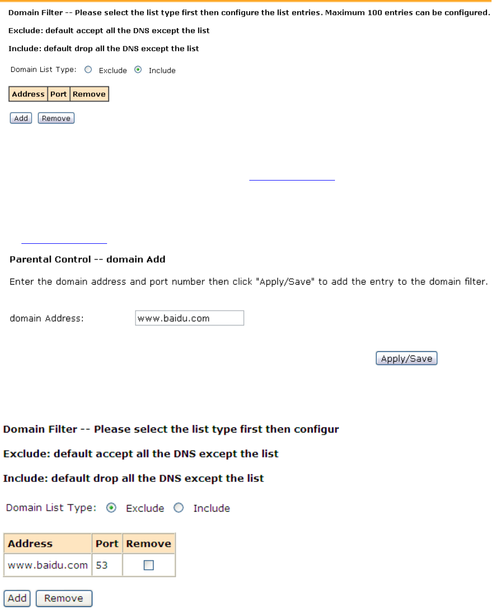
configure the list entries.
List type:
z Exclude: accept all the DNS except the list;
z Include: drop all the DNS except the list;
For Example:
If you want to forbid the user to browse www.baidu.com, you can have the following
settings:
1) Choose the Domain List Type: “Exclude”;
2) Click“add”button,enter the domain filter rule adding page, input the domain address:
www.baidu.com。
3) After entering the required settings click the Apply/Save button, you will see the
defined filter rule in the following figure.
Note: ALL the above settings will take effect after rebooting.
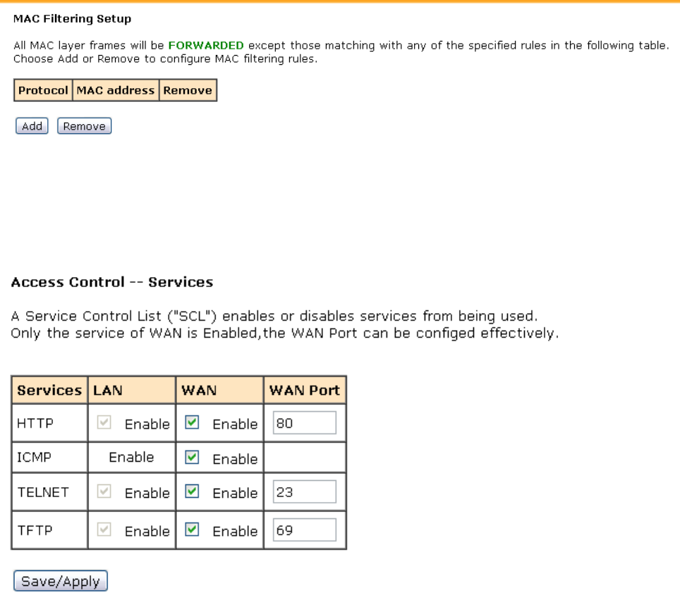
3.2.6.4. MACFilters
Please go to path: 【Firewall】→【 MAC Filter】to setup MAC filtering. All MAC layer frames will
be forwarded except those matching with any of the specified rules in the settings.
3.2.6.5. AccessControl(RemoteAccess)
Go to path:【Firewall】→【Access Control】,enter the access control page, you can enable or
disable all kinds of services.
3.2.7 Voice (VoIP)
3.2.7.1. VoIPBasicSettings
Note: Before using VOIP function,you should setup a WAN connection supporting VoIP
function.
1) Go to path:【VOIP】→【Basic Settings】,enter the basic voip configuration page.
2) Input the relevant VoIP information in this page;
3) And then click “Start SIP Client”;

For Example
If a VoIP user wants to register to the VoIP voice sip server. Related information below
z VoIP SIP server:IP:192.168.3.127, port:5060
z VoIP user account:name/password:1111
z HG-A800 can register to the Voip SIP server through PPPoE;
Steps:
1) Setup a new PPPoE WAN connection, and the service mode is VOIP_INTERNET;
2) After establishing the connection, go to the path:【Status】→【Statistics】,to view the
status of this WAN connection:
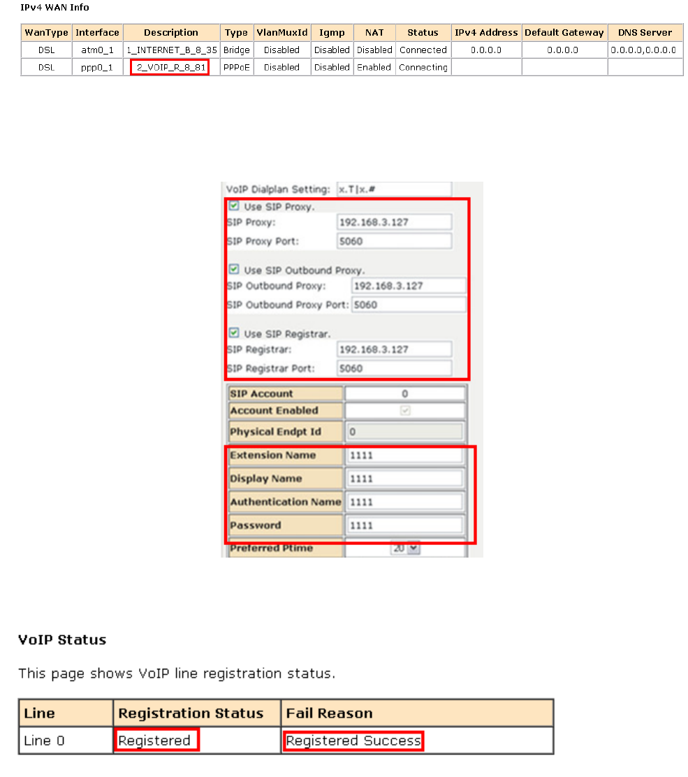
3) Go to the path:【VoIP】→【Basic Setting】→【Service Provider 0】,:
1. Click “Use SIP Proxy”, “Use SIP Outbound Proxy” and “Use SIP Registrar”, input VoIP
SIP server:192.168.3.127, port:5060.
2. input VoIP user account:name/password:1111.
4) After entering the required settings , click “Start SIP Client ”to activate the setting.
GO to the Path: 【Status】→【VoIP Status】 to show the voip line registration status:
3.2.7.2. VoIPAdvancedSettings
1) Go to the path:【VOIP】→【Advanced Settings】,you can configure the voip advanced
settings in this page, such as: Call Forwarding, Voice coding priority and T.38 support,
etc.
2) Configure the settings according to the relevant voip information。
3) After entering the required settings , click“Start SIP Client”to activate the setting.
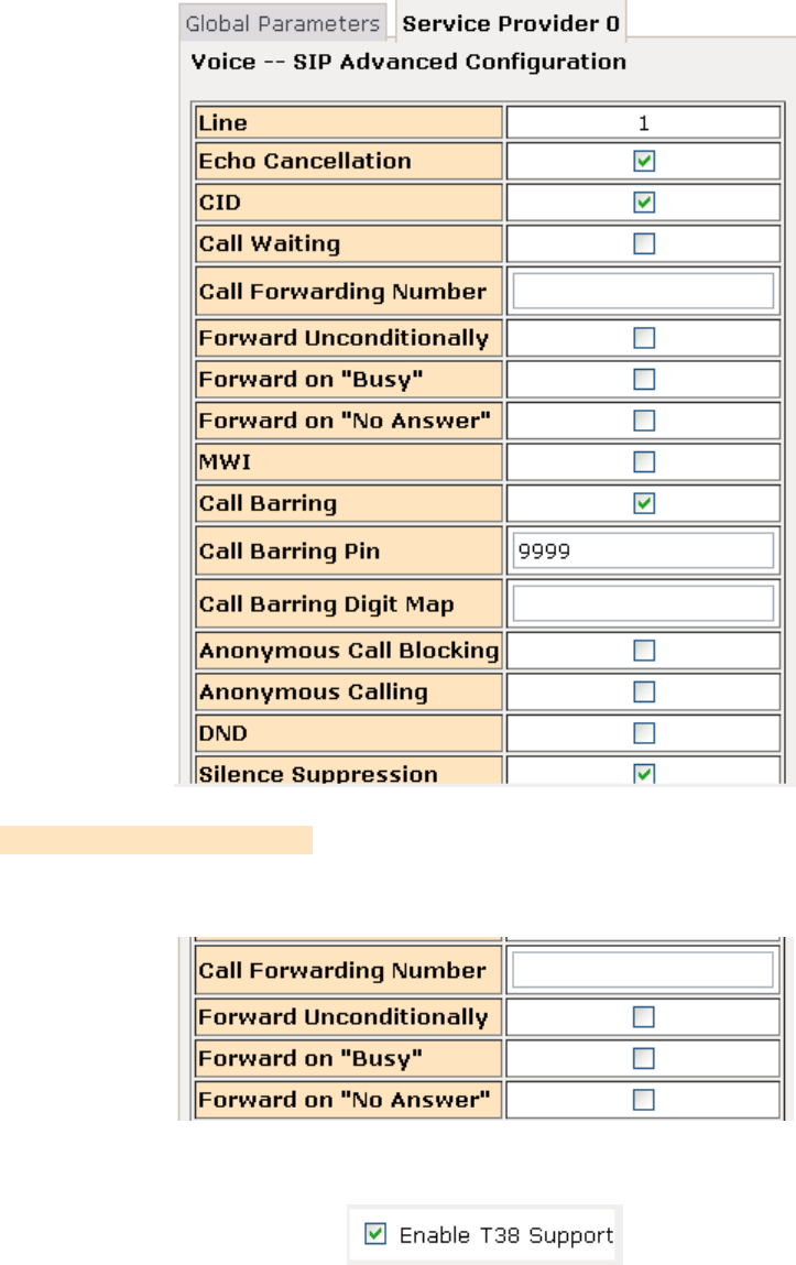
For Example
1) Call Forwarding Number: set a number to use call-forwarding. Select the conditions to
use call forwarding by ticking the required boxes.
2) Enable T38 Support: enable the T.38 function
4) After entering the required settings , click “Start SIP Client” to activate the setting.
3.2.8 Tools
3.2.8.1. AccountSettings(Users)
When you configure the CPE through an Internet browser, the system requires user name
and password to validate access permission. The factory sets the default username of
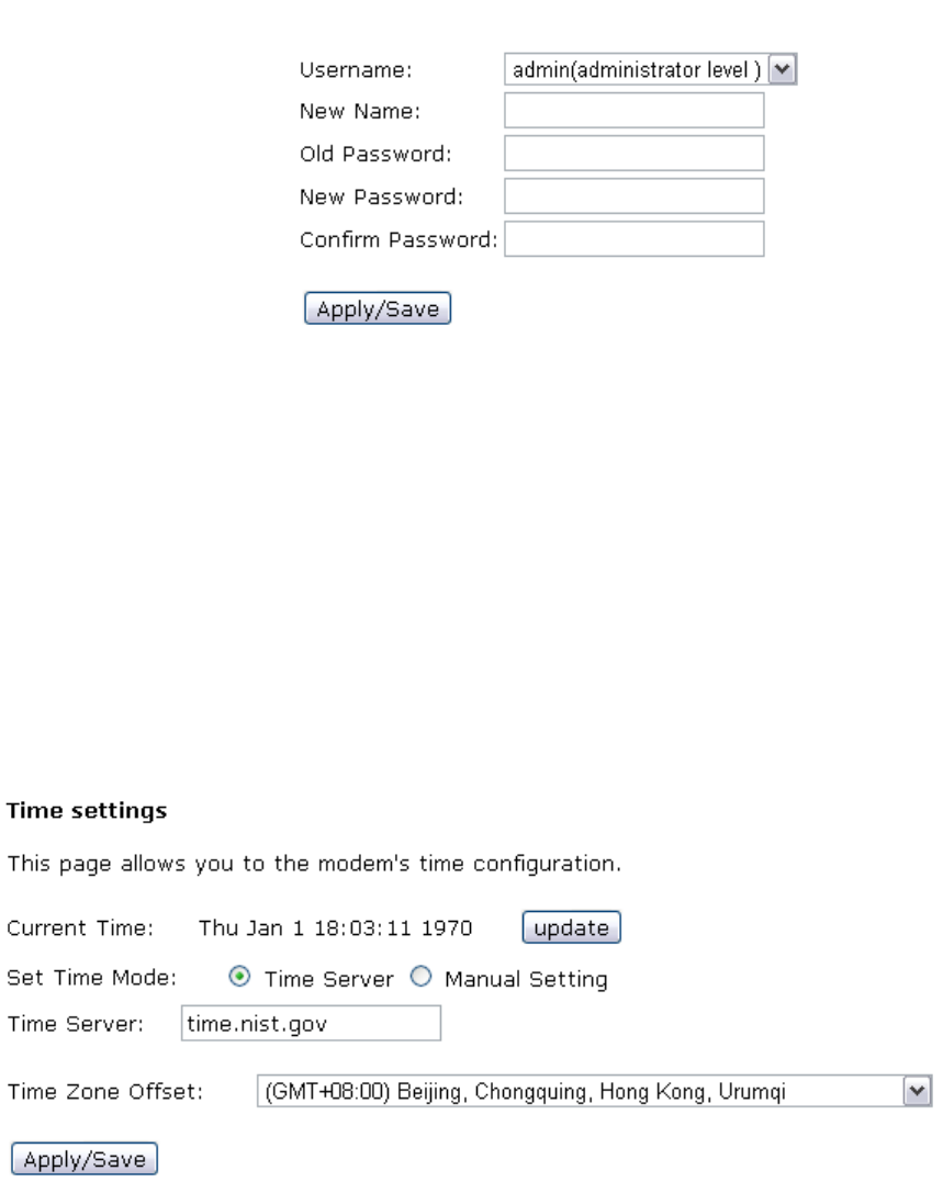
“admin” and the password of “admin”. Go to path 【Tools】→【Account Settings】, you can
choose the username and change the password.
Attention: please remember the password after change, otherwise you will need to reset
the device and will lose all configuration settings.
3.2.8.2. TimeSettings
【Tools】→【Time Settings】
From this page the current time can be set manually or the CPE can be set to obtain the
correct time from an internet time server.
Note: it is recommended that an internet time server is used when available – if the time is
set manually it will be lost in the event of a power cut or if the unit is restarted.
3.2.8.3. Diagnostics
【Tools】→【Diagnostics】

3.2.8.4. BackupSettings
To backup the current configuration to a file:
Please go to path: 【Tools】→【Backup Settings】page. Click Backup Settings button, then
a File download window will pop-up. Click Save button to download/save current
configuration of the device to the PC.

3.2.8.5. Update(Restore)Settings
Please go to path: 【Tools】→【Update Settings】 page. Click Browse button to choose a
configuration file, then click Update Settings to restore configuration.
3.2.8.6. UpdateSoftware
Please go to path: 【Tools】→【Update Software】 page. Click Browse to choose the right
software. Then click Update Software to update.
3.2.8.7. FactorySettings
To restore the CPE to the factory default configuration either press the Reset button on the
side of the unit or go to path【Tools】→【Factory Settings】 and click the Restore Default
Settings button.
Note: all user entered configuration options will be lost.
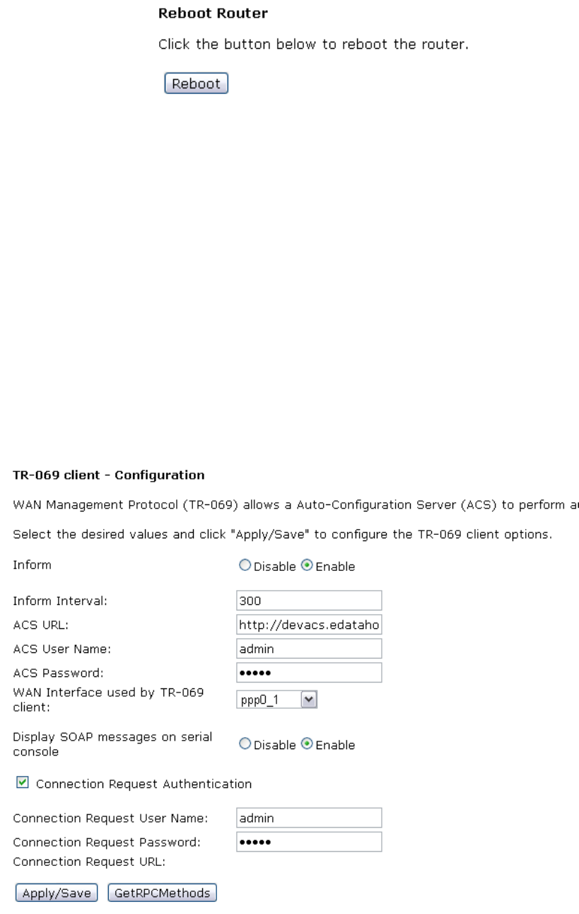
3.2.8.8. RebootRouter
To perform a soft restart of the CPE go to path【Tools】→【Reboot Router】 and click the
Reboot button. A restart takes approximately 2 minutes.
3.2.8.9. SystemLog
HG-A800 provides system log recording, you can inquire HG-A800 system event to
understand what has happened. You can set up special log recording rules, record the system
events, it is easy to know the device’s operation and safety information.
3.2.8.10. TR‐069Client
The CPE can be provisioned remotely via the use of a TR-069 remote management server.
Please go to path: 【Tools】→【 TR-069 Client】 page to setup an auto-configuration server
to perform auto-configuration, provision, collection and diagnostics to this device. Select the
desired values and click Apply/Save to configure the TR-069 client options.
Note: all the parameters in the screenshot should be matched with the TR-069 Server.
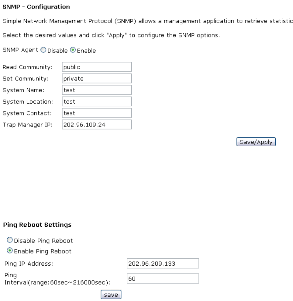
3.2.8.11. SNMP
Please go to path:【Tools】→【SNMP】 page to have the SNMP configuration, so that the SNMP
server can have HG-A800 configuration management through the SNMP protocol.
3.2.8.12. PINGReboot
The “Ping Reboot” feature can be used to monitor the status of the internet connection and
to automatically restart the CPE when the internet connection is unavailable.
【Tools】→【Ping Reboot】
4. Troubleshooting
4.1 Unable to Access Internet
4.1.1 Check the Line and the Device
1. Check the power supply indicator is on - if not, make sure the connection of power supply
is correct; Make sure the output of power supply is correct; Make sure the switch of the
power supply is turned on;
2. Check the LAN indicator for the PC is on - if not, check the cable connection between the
PC and the HG-A800; Make sure that the correct cable is used;
3. Check the DSL LED to see if it is flashing. If no fast flashing is observed within 3 minutes,
please check whether phone line has been correctly placed; whether ADSL filter is
correctly used. If multiple extensions have been installed, make sure that the filter is
installed prior to the junction box of the phone line. If the above items are confirmed and
still no fast flashing of DSL LED is observed, call the ISP to query whether ADSL service
has been provided on your line;
4. Check the DSL LED to see whether it is unable to change status from fast flashing to
always on, or whether it changes status to fast flashing after some time of being always
on. If these phenomena occur constantly, please contact your ISP with a request to
check lines and signal quality;
If there is no problem in the above items, the line and the device shall be working. Problems
may come from your computer configuration or device configuration.
4.1.2 Check Your Configuration
We explain here the configuration of PPPOE using Windows XP operation system as an
example. For other operation systems the process is similar.
1. Enter the device manager to check if Ethernet adapter is correctly installed. If any
problem exists, please re-install it;
2. Check the configuration of Ethernet adapter in PC. Try to manually set IP address that is
in band 192.168.1.X without conflict.
3. Try to run command “ping 192.168.1.1” in a command prompt (Start, Programs,
Accessories, Command Prompt). If the response returns “time out”, please check
Ethernet connection and IP settings;
4. If the HG-A800 is reachable, try to ping a known internet IP, e.g. a DNS server: “ping
208.67.222.222”.
z If ping is reachable, there are no problems in the HG-A800. Please go to step 5;
z If ping is not reachable, see step 6 and check if the configuration is correct.
5. Please try to ping a internet URL, e.g. “ping www.google.com”.

z If ping is reachable, there are problems in the network settings. Please check the
settings of the PC terminal, e.g. whether the security level is too high, or whether
anti-virus or firewall is installed;
z If ping is not reachable, check the DNS setting of Ethernet adapter.
Note 1:The precondition is that LAN settings in the HG-A800 have not been modified.
Note 2:To start a Command Prompt in Windows click on the Start menu, Programs,
Accessories, Command Prompt
Note 3:The returned values of ping command in the following format show the standard of
“reachable”
6. If ping of the modem is reachable but ping of the internet fixed IP is unreachable,
attention should be concentrated upon device settings. Please enter the web interface
following the instructions in this manual.
(1) Check first the number of connections. If more than one connection exists, for
troubleshooting, delete unused connections and leave the one connection you are using.
(2) Check the connection to see whether correct “type” is selected. It’s normal to choose
login type of PPPoE. When you use PPPoE to login, the following information should be
provided: VPI and VCI, which can be queried from your ISP, user name and password.
(3) Then make sure that “using NAT” and “default gateway” have been selected with a
tick. Check whether “connect on demand” has been selected with a tick. If it is selected, the
connection is activated only when traffic to the internet arrives. If not selected, check “keep
connection”, which should be set to 0 if you demand to keep connection
Make sure that the above parameters are saved after configuration.
FCC WARNING
This device complies with Part 15 of the FCC Rules. Operation is subject to the following two
conditions:
(1) This device may not cause harmful interference, and
(2) this device must accept any interference received, including interference that may cause
undesired operation.
NOTE 1: This equipment has been tested and found to comply with the limits for a Class B digital
device, pursuant to part 15 of the FCC Rules. These limits are designed to provide reasonable
protection against harmful interference in a residential installation. This equipment generates, uses
and can radiate radio frequency energy and, if not installed and used in accordance with the
instructions, may cause harmful interference to radio communications. However, there is no
guarantee that interference will not occur in a particular installation. If this equipment does cause
harmful interference to radio or television reception, which can be determined by turning the
equipment off and on, the user is encouraged to try to correct the interference by one or more of
the following measures:
- Reorient or relocate the receiving antenna.
- Increase the separation between the equipment and receiver.
-Connect the equipment into an outlet on a circuit different from that to which the receiver is
connected.
-Consult the dealer or an experienced radio/TV technician for help.
NOTE 2: Any changes or modifications to this unit not expressly approved by the party
responsible for compliance could void the user's authority to operate the equipment.
The transmitter must not be co-located or operated in conjunction with any other antenna or
transmitter. This equipment complies with the FCC RF radiation exposure limits set forth for an
uncontrolled environment. This equipment should be installed and operated with a minimum
distance of 20cm between the radiator and any part of your body.