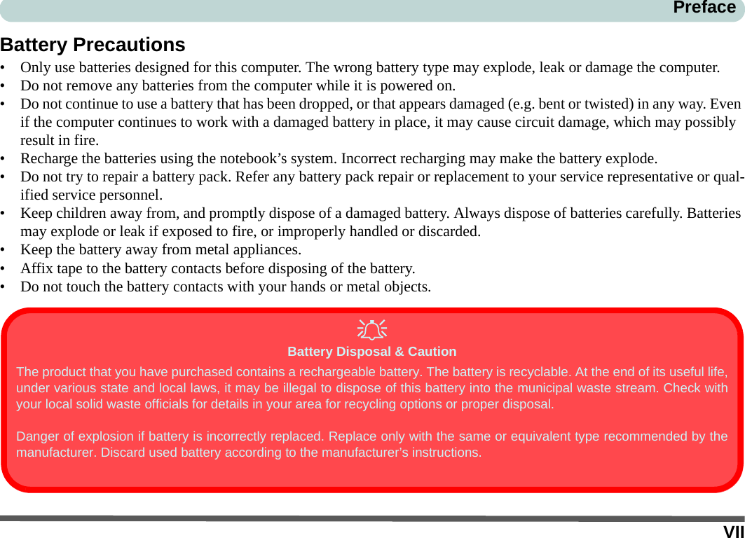
CLEVO M72R Notebook User Manual Part I
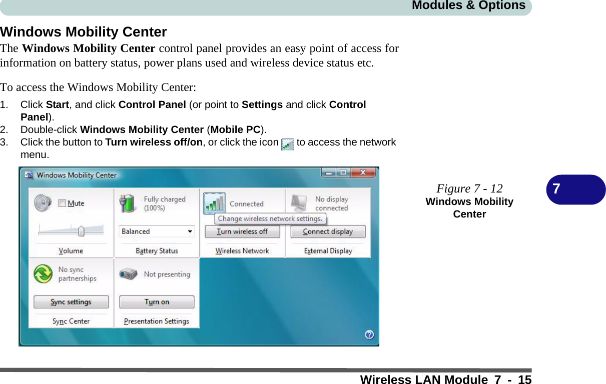
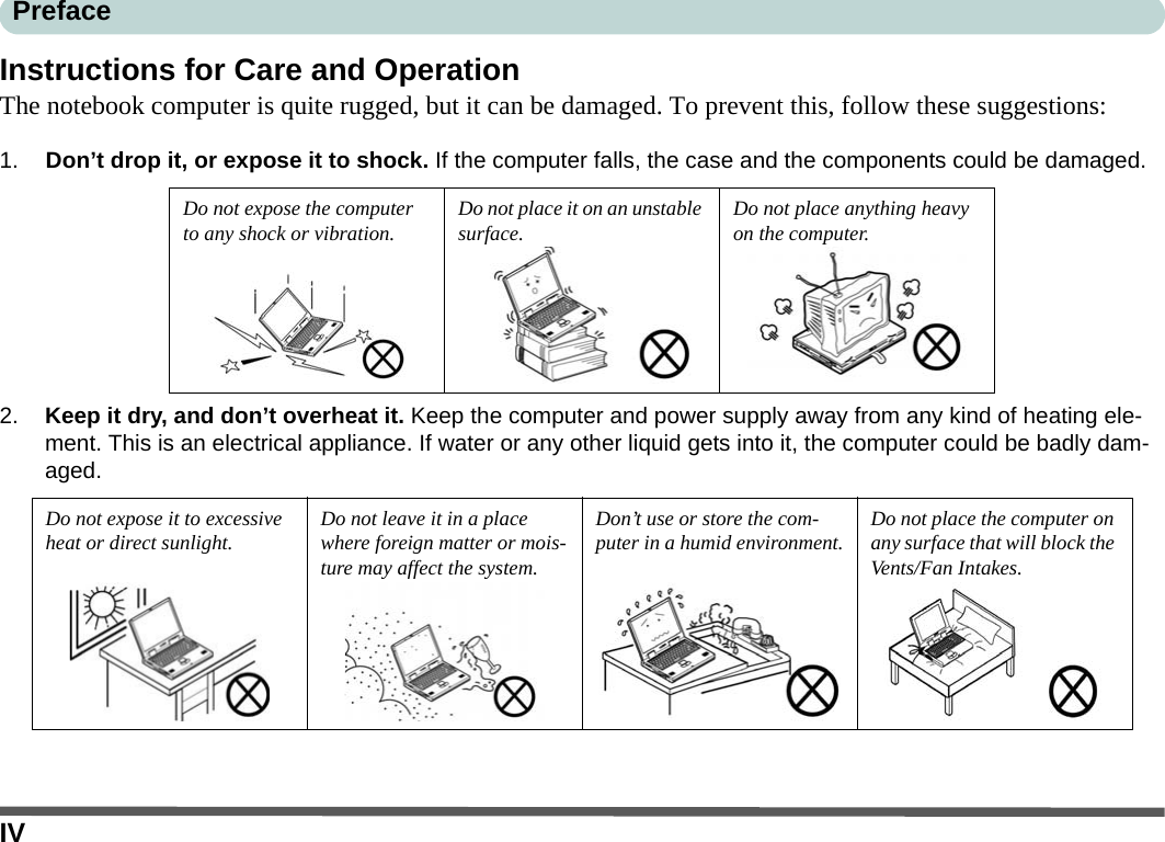
CLEVO Co. Notebook Users Manual Part I
UserManual.wiki
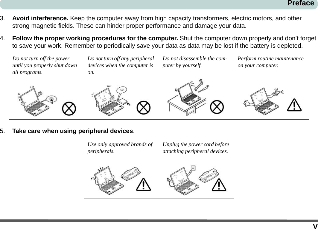
>
CLEVO
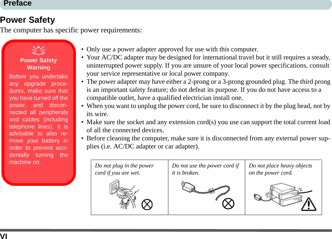
>
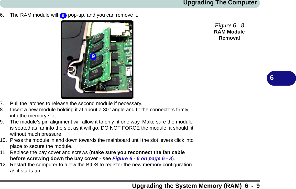
M72R User Manual
>
Users Manual Part I
Contents
1.
Users Manual Part I
2.
Users Manual Part II
3.
Users Manual Part III
Users Manual Part I
Navigation menu
Upload a User Manual
Namespaces
Wiki Guide
HTML
PDF
Info
Views
User Manual
Discussion / Help
Navigation


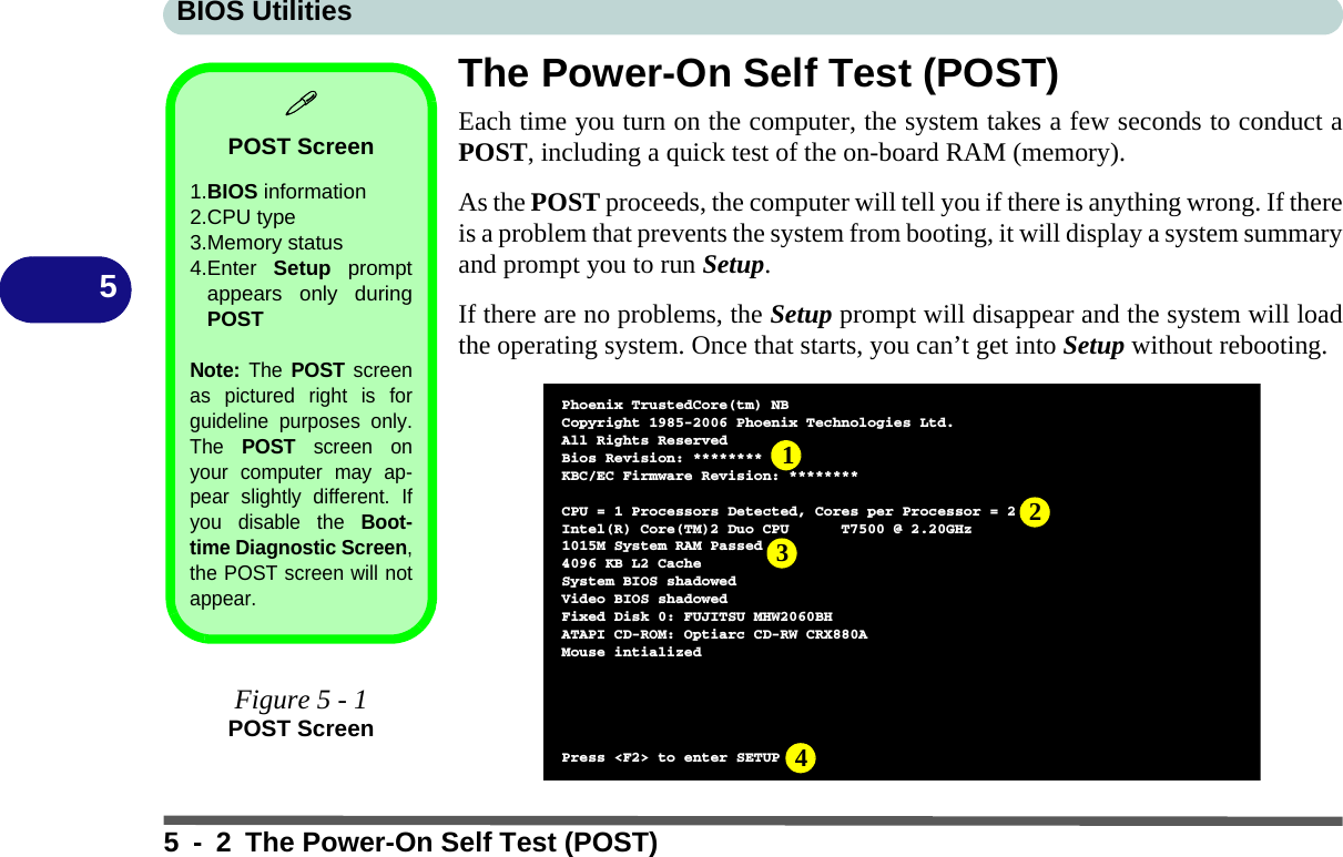
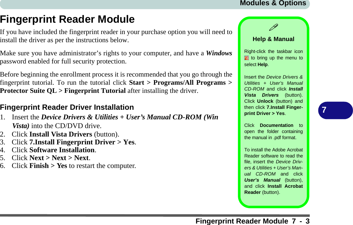
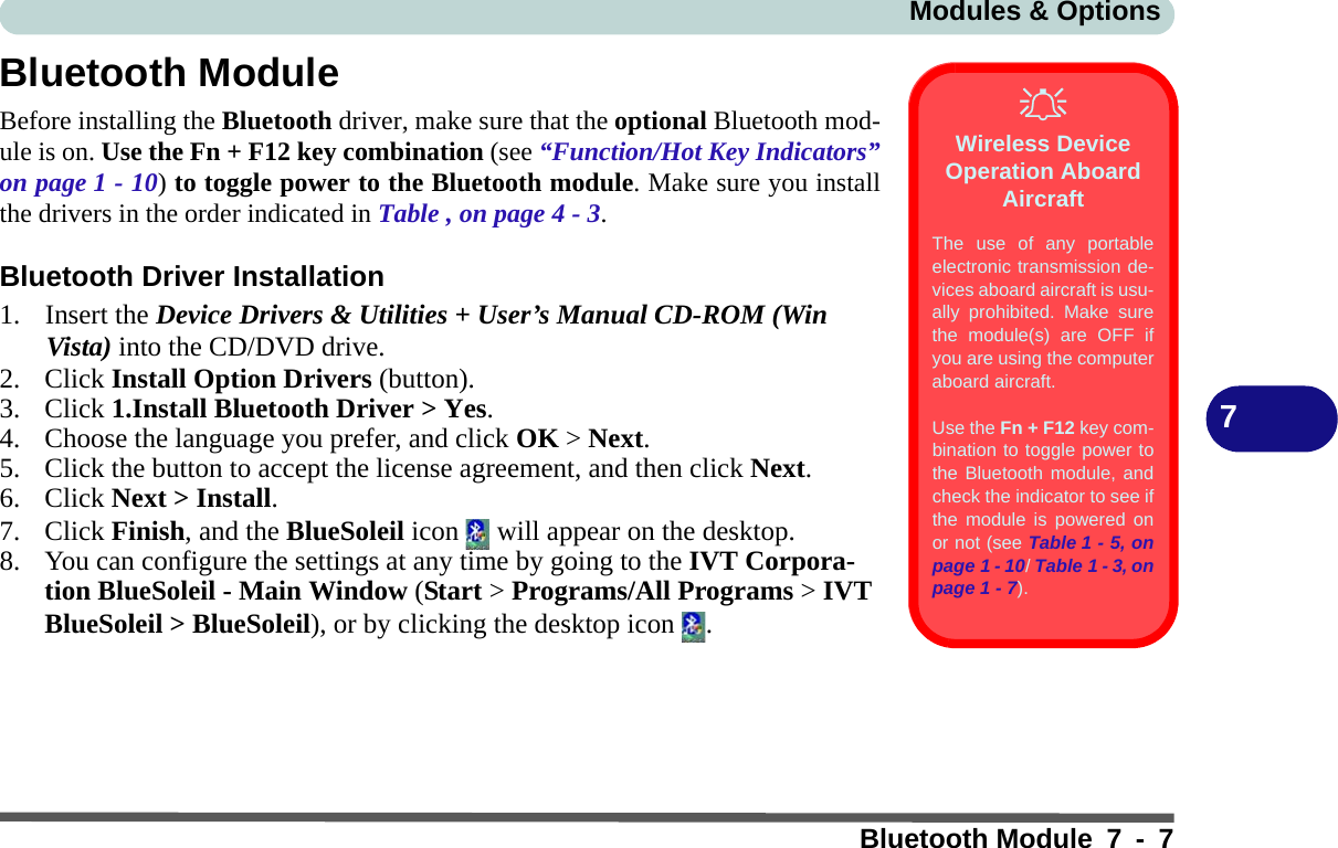
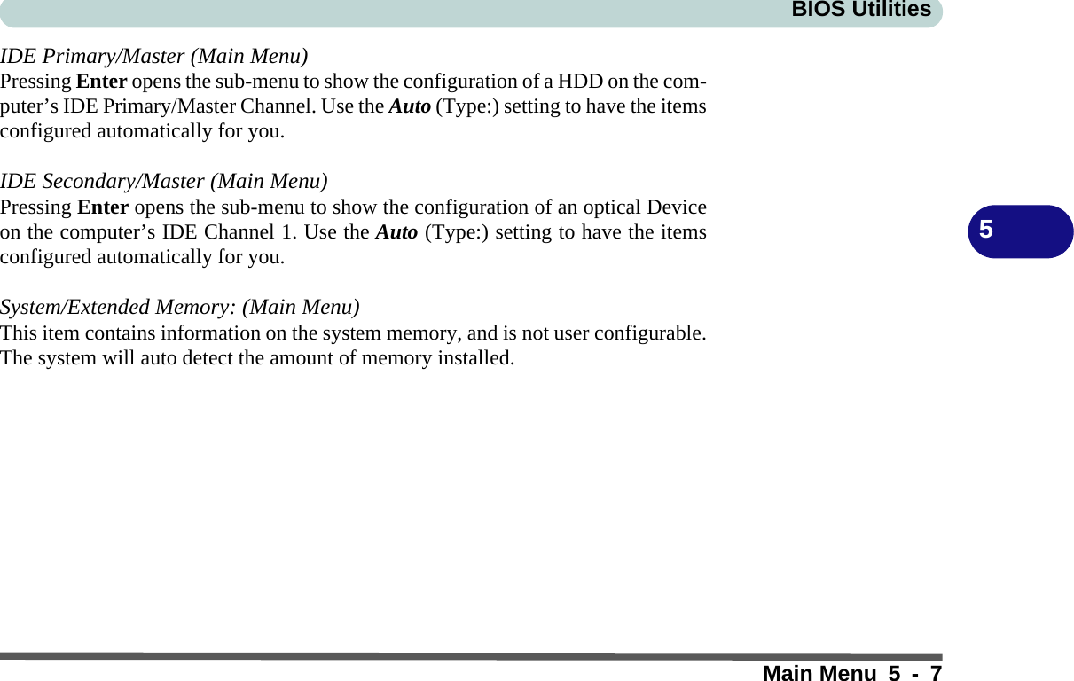
![BIOS Utilities5-6Main Menu5Main MenuSystem Time & Date (Main Menu)The hour setting uses the 24-hour system (i.e., ØØ = midnight; 13 = 1 pm). If youcan change the date and time settings in your operating system, you will also changethese settings. Some applications may also alter data files to reflect these changes.Figure 5 - 2Main MenuMain Advanced Security Boot ExitF1 Help Select Item -/+ Change Values F9 Setup DefaultsEsc Exit Select Menu Enter Select Sub-Menu F10 Save and ExitItem Specific Help<Tab>, <Shift Tab>, or<Enter> selects field.MainBIOS Revision ********System Time: [22:12:05]System Date: [06/12/2007] IDE Primary/Master [FUJITSU MHW2060BH-(S1)] IDE Secondary/Master [Optiarc CD-RW CRX880A-(SM]System Memory 640 KBExtended Memory 1038336 KBPhoenix TrustedCore(tm) Setup Utility](https://usermanual.wiki/CLEVO/M72R.Users-Manual-Part-I/User-Guide-806510-Page-76.png)
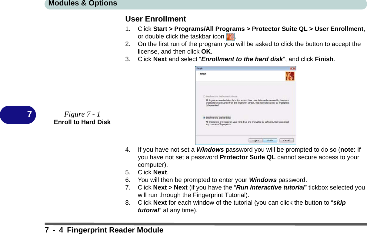
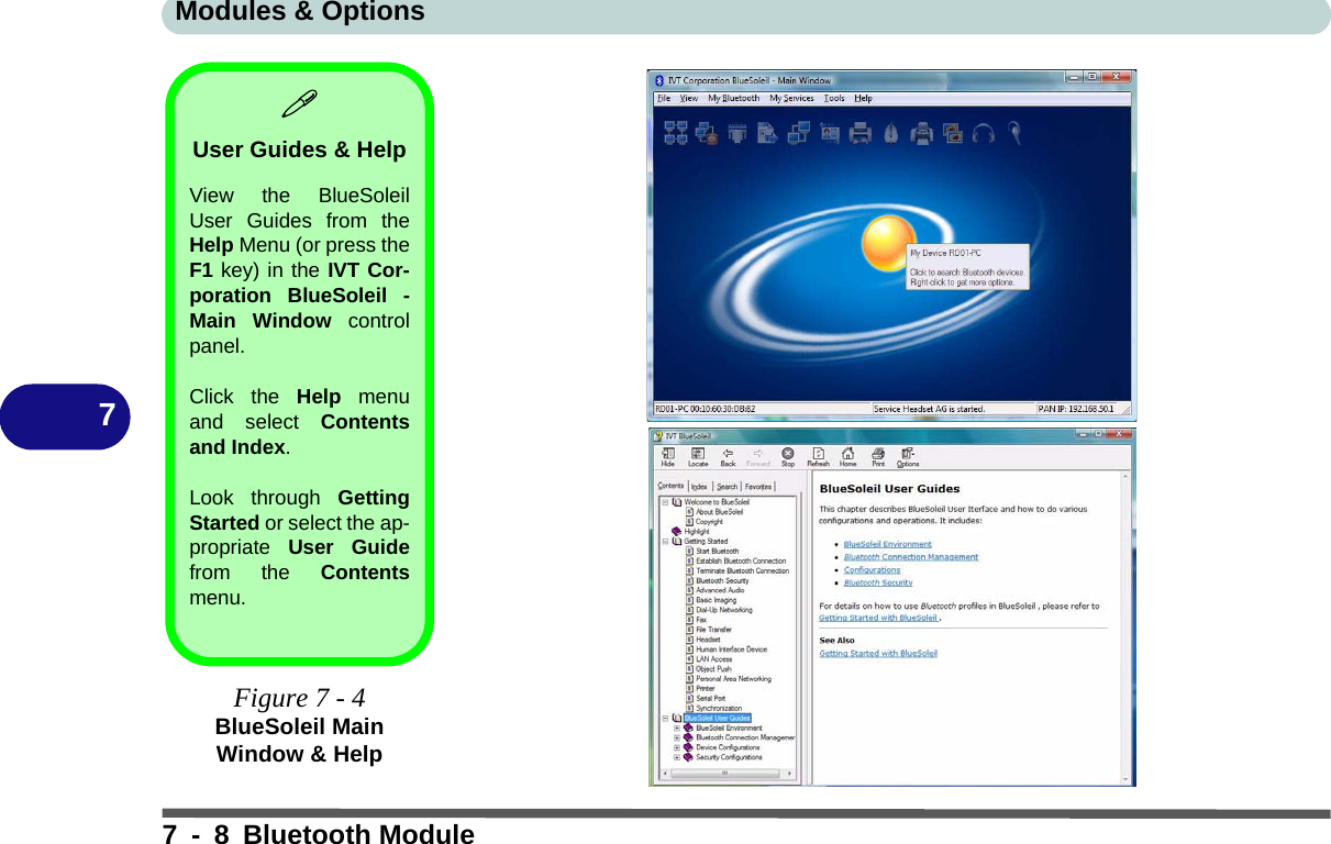
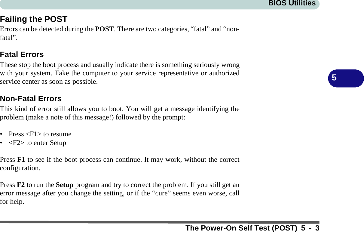
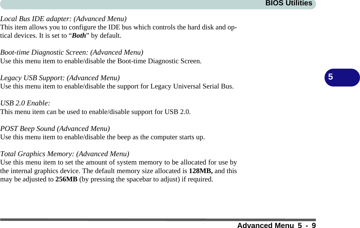
![BIOS Utilities5 - 8 Advanced Menu5Advanced MenuReset Configuration Data: (Advanced Menu)This item is set to No as default. You can change the setting to Yes if you have in-stalled a new add-on which has reconfigured the system, resulting in such a serioussystem conflict that the operating system is unable to boot.Figure 5 - 3Advanced Menu Main Advanced Security Boot ExitF1 Help Select Item -/+ Change Values F9 Setup DefaultsEsc Exit Select Menu Enter Select Sub-Menu F10 Save and ExitItem Specific HelpAdvancedSelect 'Yes' if youwant to clear theExtended SystemConfigurationData (ESCD) area.Phoenix TrustedCore(tm) Setup UtilityReset Configuration Data: [No]Local Bus IDE adapter: [Both]Boot-time Diagnostic Screen: [Enabled]Legacy USB Support: [Enabled]USB 2.0 Enable: [Enabled]POST Beep Sound [Disabled]Total Graphics Memory: [128MB]](https://usermanual.wiki/CLEVO/M72R.Users-Manual-Part-I/User-Guide-806510-Page-78.png)
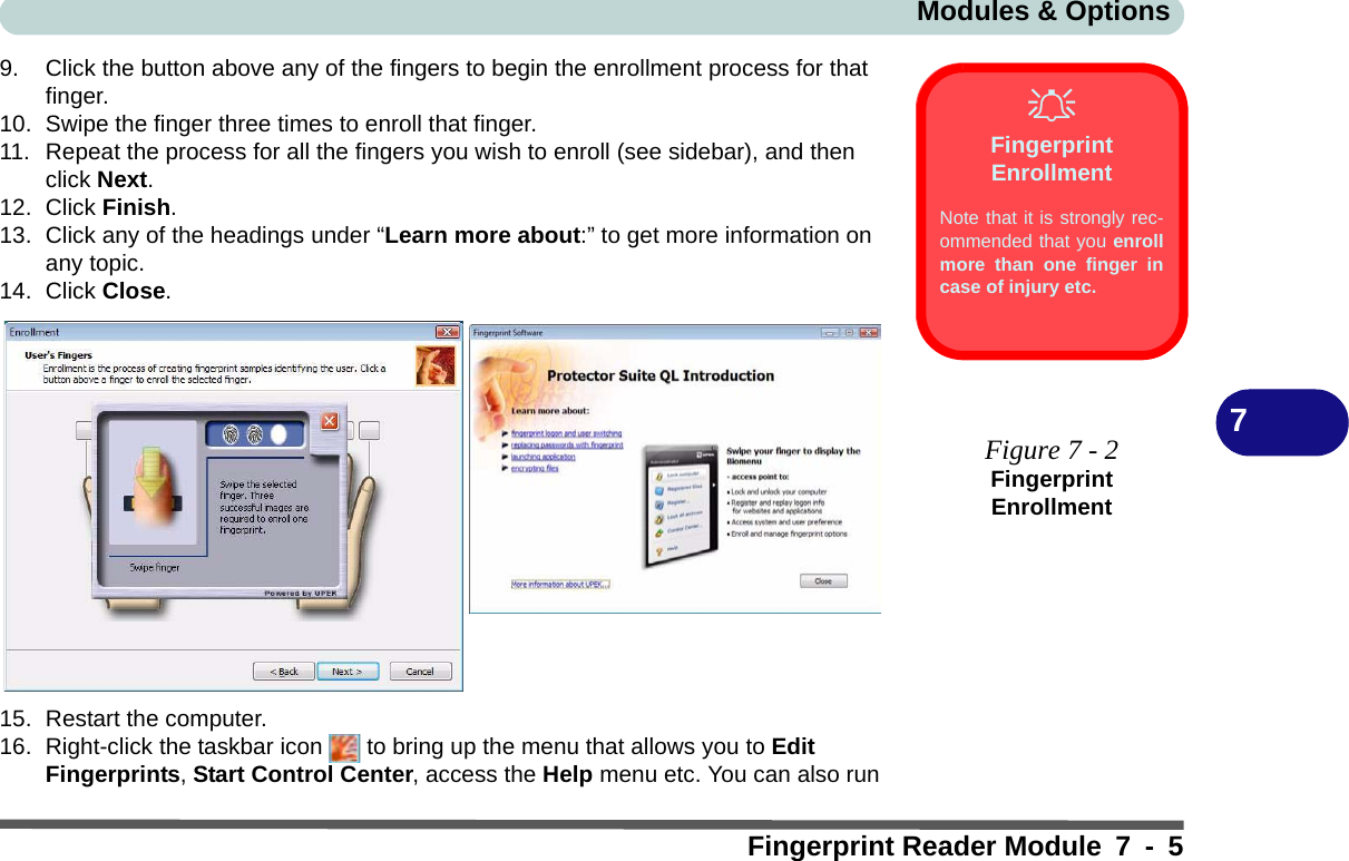
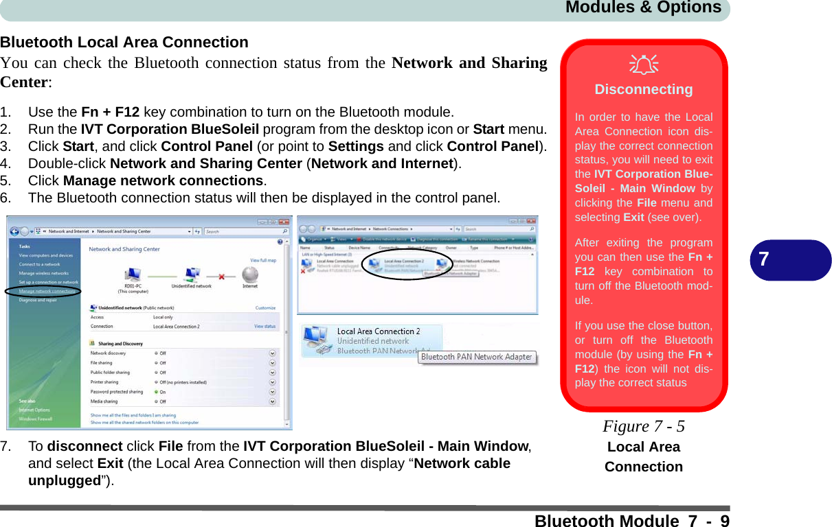
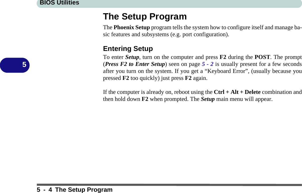
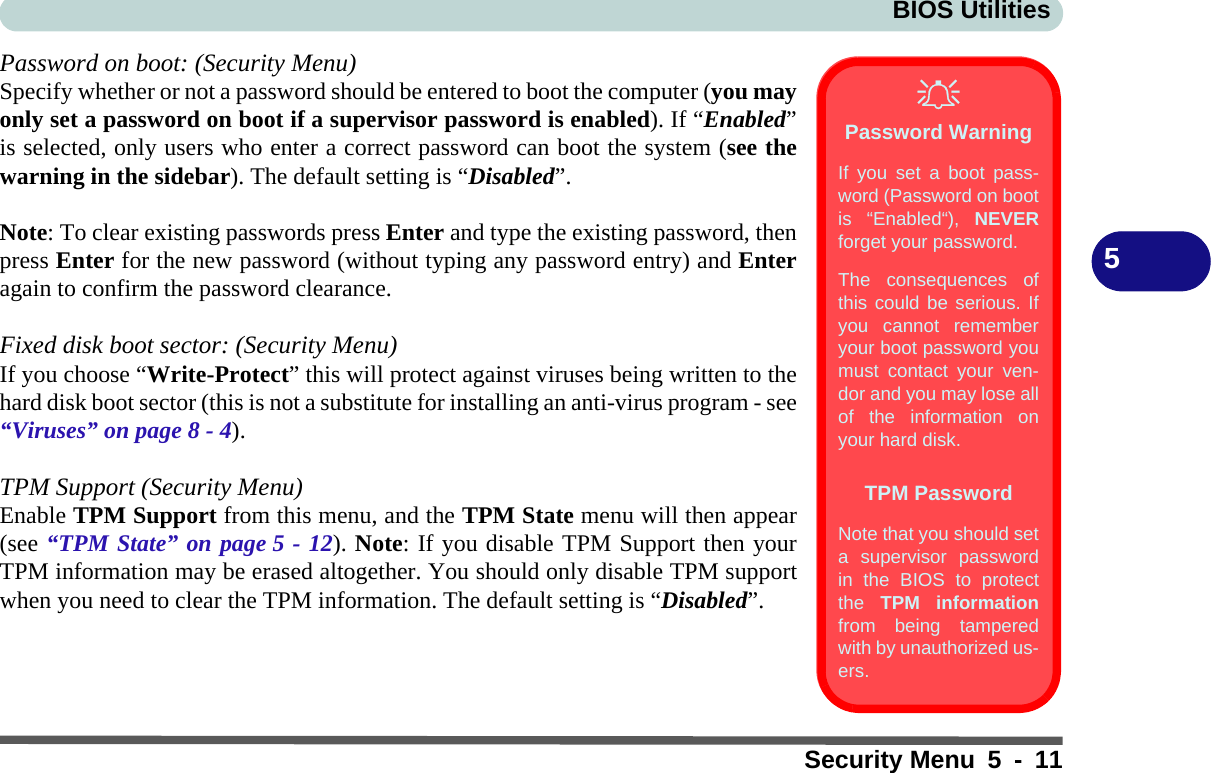
![BIOS Utilities5 - 10 Security Menu5Security MenuSet Supervisor Password (Security Menu)You can set a password for access to the Phoenix TrustedCore Setup Utility. Thiswill not affect access to the computer OS, (only the Phoenix TrustedCore SetupUtility).Security MenuThe changes youmake here affect theaccess to the Setuputility itself, and alsoaccess to your ma-chine as it boots up af-ter you turn it on.These settings do notaffect your machine ornetwork passwordswhich will be set inyour software OS.Figure 5 - 4Security MenuMain Advanced SSeeccuurriittyyBoot ExitF1 Help Select Item -/+ Change Values F9 Setup DefaultsEsc Exit Select Menu Enter Select Sub-Menu F10 Save and ExitItem Specific HelpEnable Trusted PlatformModule supportSecuritySupervisor Password Is: ClearSet Supervisor Password [Enter]Password on boot: [Disabled]Fixed disk boot sector: [Normal]TPM Support [Disabled]Phoenix TrustedCore(tm) Setup Utility](https://usermanual.wiki/CLEVO/M72R.Users-Manual-Part-I/User-Guide-806510-Page-80.png)
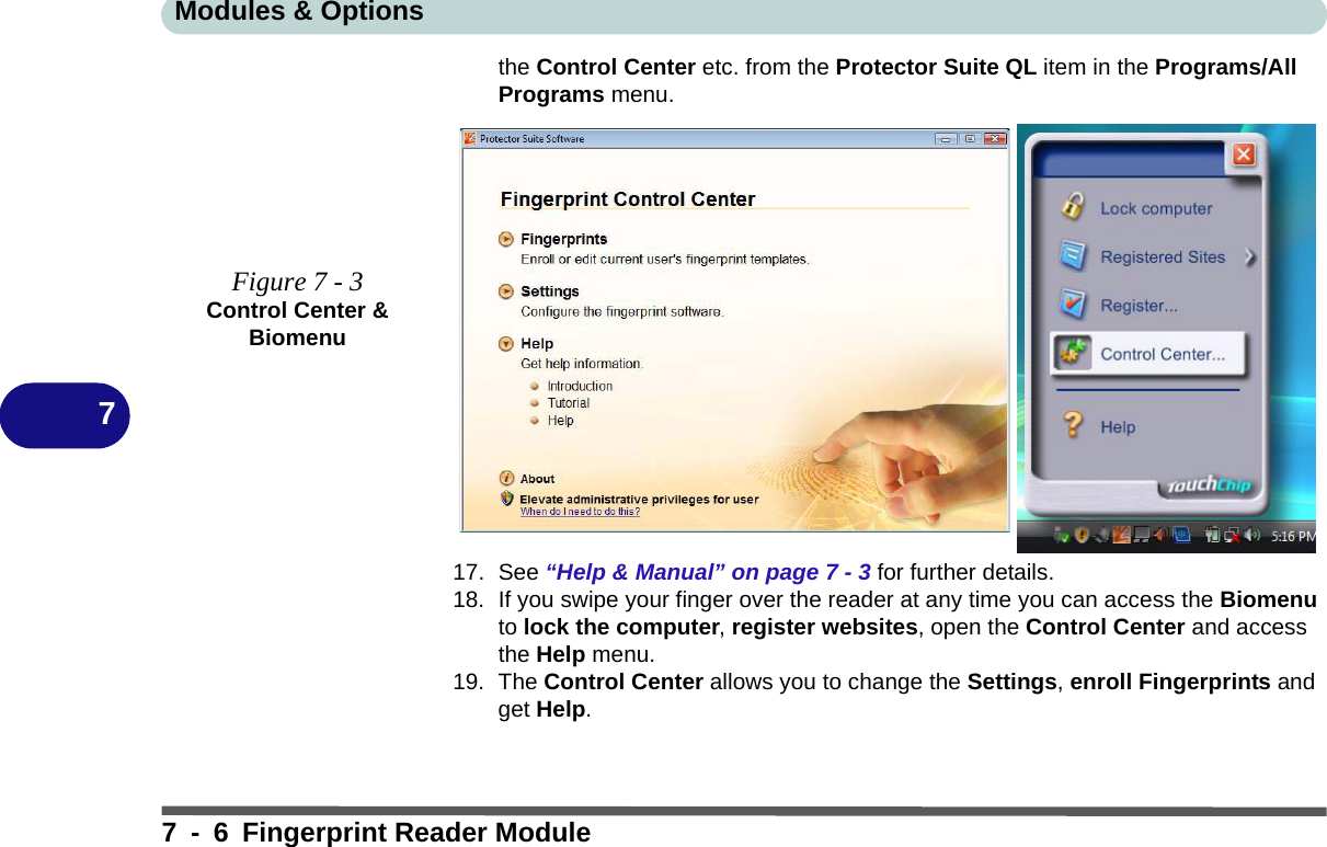
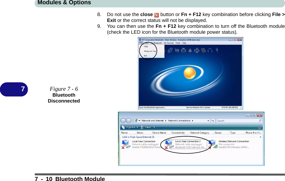
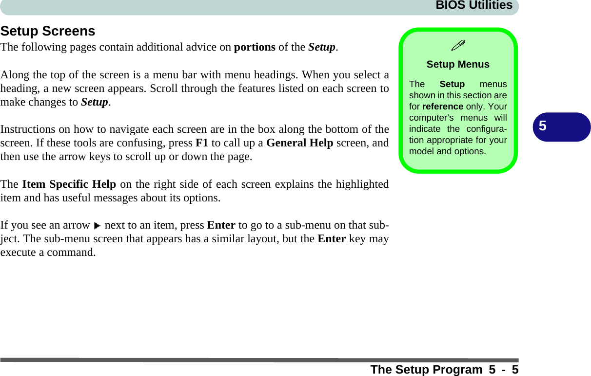
![BIOS Utilities5 - 12 TPM State5TPM StateChange TPM State (TPM State)This menu allows you to set the level of TPM functionality. You can enable/disablethe TPM function altogether, or clear all existing TPM information. Note: If you clear all TPM information it will be erased altogether and the informa-tion will need to be reconfigured.Main Advanced Security Boot ExitF1 Help Select Item -/+ Change Values F9 Setup DefaultsEsc Exit Select Menu Enter Select Sub-Menu F10 Save and ExitItem Specific HelpChanges TPM StateTPM StateCurrent TPM State: Enabled and DeactivatedChange TPM State [No Change ]No ChangeEnable & ActivateDeactivate & DisableClearPhoenix TrustedCore(tm) Setup UtilityTPM State MenuTo access this menuyou must first enableTPM support from thesecurity menu (seepage 5 - 11).Password ProtectionNote that you should seta supervisor passwordin the BIOS to protectthe TPM informationfrom being tamperedwith by unauthorized us-ers.Figure 5 - 5TPM State](https://usermanual.wiki/CLEVO/M72R.Users-Manual-Part-I/User-Guide-806510-Page-82.png)