Contents
- 1. Users Manual Part I
- 2. Users Manual Part II
- 3. Users Manual Part III
Users Manual Part II
Modules & Options
PC Camera Module 7 - 19
7
Figure 7 - 13
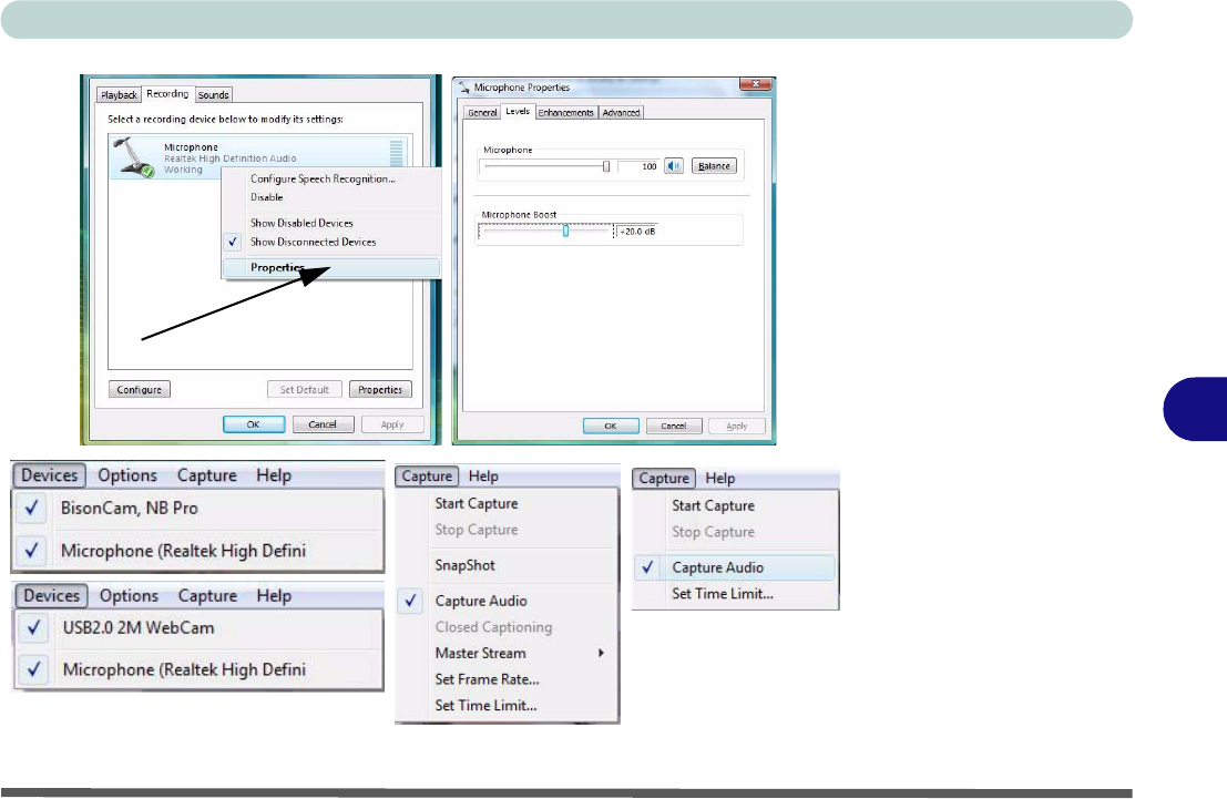
Audio Setup for PC
Camera
Right-click

Modules & Options
7 - 20 PC Camera Module
7
BisonCap (for 1.3M pixel camera module)
BisonCap is a video viewer useful for general purpose video viewing and testing,
and can capture video files to .avi format.
1. Run the BisonCap program from the Start > Programs/All Programs > Bison-
Cam menu (it is recommended that you set the capture file before the capture
process - see Set Capture File below).
2. Go to the Capture menu heading (if you wish to capture audio check “PC Camera
Audio Setup (all camera modules)” on page 7 - 18) and select Start Capture.
3. On the first run of the program (if you have not set the captured file) you will be
asked to choose a file name and size (see the sidebar - Pre-Allocating File
Space) for the captured file. Click Start Capture again.
4. Click OK to start capturing the video, and press Esc to stop the capture.
5. If you wish to, you may go to the File menu and select Save Captured Video
As..., choose a file name and location, and then click Open (you can view the file
using the Windows Media Player).
Set Capture File
In the BisonCap program you will only be asked to set the capture file name on the
first run of the program. When you run the program the next time the file will auto-
matically be overwritten with the newly captured file. To avoid overwriting files you
can go to the Set Capture File.. option in the File menu, and set the file name and
location before capture. Set the name and location then click Open (you can choose
Cancel to ignore the file size if prompted).
Pre-Allocating File
Space
You may pre-allocate the
file size for the capture file
in the
BisonCap
pro-
gram. You can choose to
ignore this by clicking
Cancel
.
Pre-allocating space on
the hard disk can improve
the capture quality (par-
ticularly of large capture
files), by reducing the
amount of work the hard
disk has to do in finding
space for the video data
as it is being captured.
Modules & Options
PC Camera Module 7 - 21
7
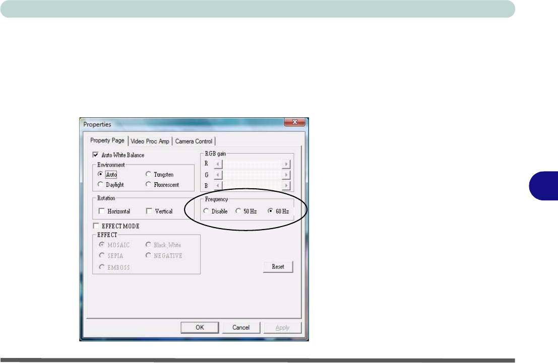
Eliminating Screen Flicker (BisonCap)
If you find that the video screen in the BisonCap program is flickering, you can try
to adjust the setting in the Video Capture Filter options.
1. Run the BisonCap program.
2. Go to Options and scroll down to select Video Capture Filter....
3. Click either 50Hz or 60Hz under Frequency in Property Page (tab).
Figure 7 - 14
Video Capture Filter

Modules & Options
7 - 22 PC Camera Module
7
Video View (for 2.0M pixel camera module)
Video View is a video viewer useful for general purpose video viewing and testing,
and can capture video files to .avi format.
1. Run the Video View program from the Start > Programs/All Programs > USB2.0
PC Camera menu (it is recommended that you set the capture file before the
capture process - see Set Capture File below).
2. Go to the Capture menu heading (if you wish to capture audio check “PC Camera
Audio Setup (all camera modules)” on page 7 - 18) and select Start Capture.
3. Click OK (the file location will be displayed in the pop-up box) to start capturing the
video, and press Esc to stop the capture.
Set Capture File
Prior to capturing video files you may Set Capture File... To avoid overwriting files
you can go to the Set Capture File.. option in the File menu, and set the file name
and location before capture. Set the name and location then click Open (you can
choose Cancel to ignore the file size if prompted).
Pre-Allocating File
Space
You may pre-allocate the
file size for the capture file
in the
Video View
pro-
gram.
Pre-allocating space on
the hard disk can improve
the capture quality (par-
ticularly of large capture
files), by reducing the
amount of work the hard
disk has to do in finding
space for the video data
as it is being captured.
Modules & Options
PC Camera Module 7 - 23
7
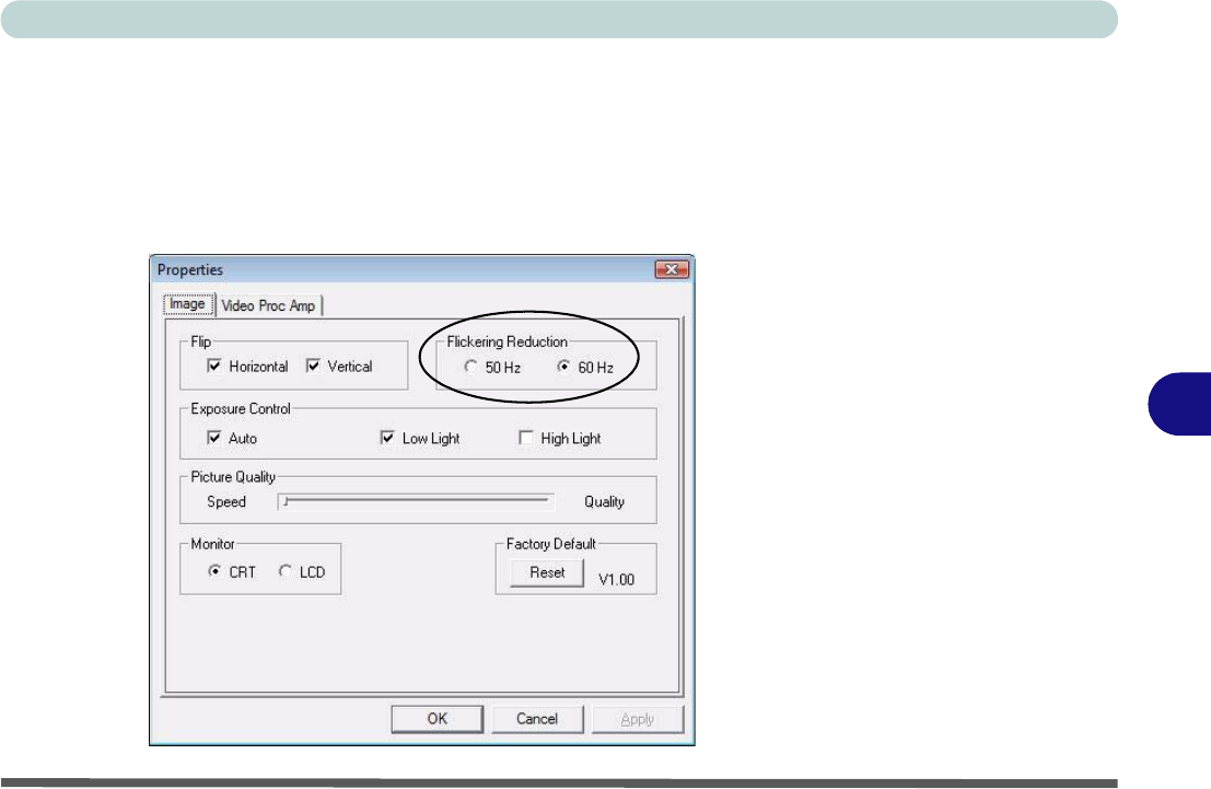
Eliminating Screen Flicker (Video View)
If you find that the video screen in the Video View program is flickering, you can
try to adjust the setting in the Video Capture Filter options.
1. Run the Video View program.
2. Go to Options and scroll down to select Video Capture Filter....
3. Click either 50Hz or 60Hz under Flickering Reduction in Image (tab).
Figure 7 - 15
Video Capture Filter
Modules & Options
7 - 24 PC Camera Module
7
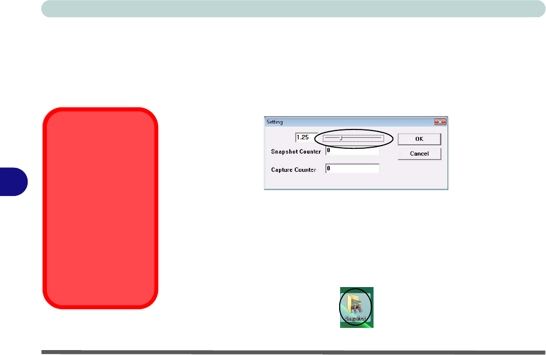
Zoom (Video View)
If you have enabled digital zoom when installing the 2.0M Pixel Camera driver you
may use the Options > Setting menu to zoom the camera in and out.
1. Run the Video View program.
2. Go to Options and scroll down to select Setting.
3. Use the slider to adjust the zoom level, and click OK to save the setting.
Still Image Capture (Video View)
You can capture still images by using the Snapshot command from the Capture
menu.
1. Run the Video View program.
2. Go to Capture and select Snapshot.
3. The picture (in JPEG format) will be placed in the Snapshot folder on the desktop.
Figure 7 - 16
Setting
Snapshot Folder
The Snapshot folder’s
default location is on the
desktop. Do not move
this folder or an error
may appear when you
try to take a still picture.
If you accidentally de-
lete or move the folder,
you can create a new
Snapshot folder on the
desktop in order to cap-
ture the files.
Figure 7 - 17
Snapshot Folder
Modules & Options
Trusted Platform Module 7 - 25
7
Trusted Platform Module
Before setting up the TPM functions you must initialize the security platform.
Initializing TPM
1. Restart the computer.
2. Enter the PhoenixBIOS Setup Utility by pressing F2 during the POST.
3. Use the arrow keys to select the Security menu.
4. Select TPM Support and set the item to Enabled.
5. The TPM State menu will then appear.
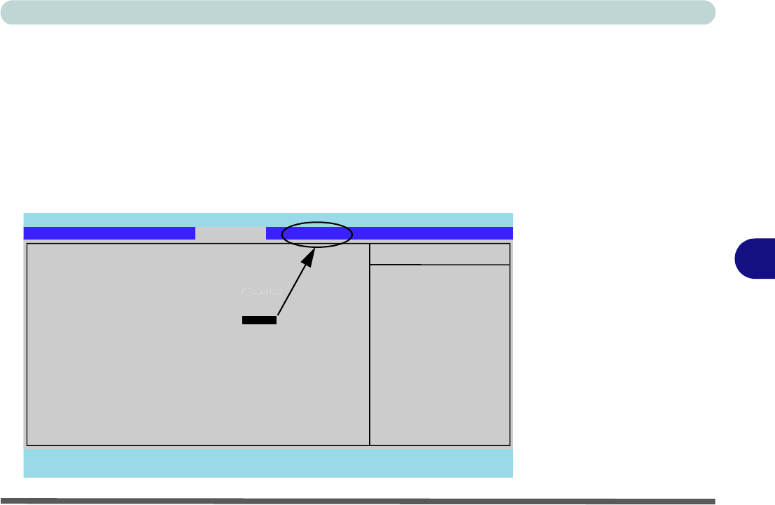
Figure 7 - 18
TPM Support
Main Advanced S
S
e
e
c
c
u
u
r
r
i
i
t
t
y
y
TPM State Boot Exit
F1 Help Select Item -/+ Change Values F9 Setup Defaults
Esc Exit Select Menu Enter Select Sub-Menu F10 Save and Exit
Item Specific Help
Enable Trusted Platform
Module support
Security
Phoenix TrustedCore(tm) Setup Utility
Supervisor Password Is: Clear
Set Supervisor Password [Enter]
Password on boot: [
D
i
s
a
b
l
e
d
]
Fixed disk boot sector: [Normal]
TPM Support [Enabled]
Modules & Options
7 - 26 Trusted Platform Module
7
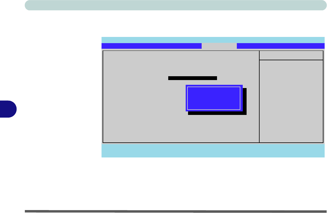
6. Use the arrow keys to select the TPM State menu.
7. Select TPM State, and set the item to Enable & Activate.
8. Press F10 to save the changed BIOS information, exit the BIOS and restart the
computer.
9. If you make any changes to the TPM State you will be asked to Execute/Reject
the change after restart (“Physical Presence Operations” on page 5 - 13).
10. You can now install the TPM driver (see overleaf).
Figure 7 - 19
TPM State Main Advanced Security Boot Exit
F1 Help Select Item -/+ Change Values F9 Setup Defaults
Esc Exit Select Menu Enter Select Sub-Menu F10 Save and Exit
Item Specific Help
Changes TPM State
TPM State
No Change
Enable & Activate
Deactivate & Disable
Clear
Current TPM State: Enabled and Deactivated
Change TPM State [Enable & Activate ]
Phoenix TrustedCore(tm) Setup Utility

Modules & Options
Trusted Platform Module 7 - 27
7
TPM Module Driver Installation
1. Insert the Device Drivers & Utilities + User’s Manual CD-ROM (Win
Vista) into the CD/DVD drive.
2. Click Install Option Drivers (button).
3. Click 4.Install TPM Driver > Yes.
4. Click Next.
5. Click the button to accept the license agreement, and then click Next.
6. Click Next > Next > Install.
7. Click Finish.
8. Run the TPM application program from the shortcut on the desktop, or
from the TPM Secure Tools item in the Start > Programs/All Programs
menu.
Modules & Options
7 - 28 Trusted Platform Module
7
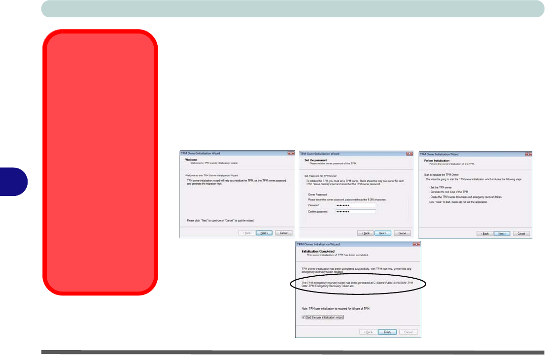
Initializing TPM
On the first run of the program you will need to initialize the TPM.
1. Run the application from the Security Manager shortcut on the desktop, or from
the TPM Secure Tools item in the Start > Programs/All Programs menu.
2. Click Next.
3. Type a TPM Owner Password, and then retype to confirm the password.
4. Click Next (you may want to add Owner Password Tips) > Next to begin the owner
initialization process.
5. Click Finish to start User Initialization process.
Password Warning
Do not lose the pass-
word. If you do so you
will be unable to make
administrative changes
unless you clear the
TPM. This could then re-
sult in data loss.
Recovery Token
Note the location of the
emergency recovery to-
ken. It is recommended
that you save the file to
removable media such
as a USB Flash drive (or
backup using the tool
provided - see page 7 -
36).
Figure 7 - 20
TPM Owner
Initialization
Modules & Options
Trusted Platform Module 7 - 29
7
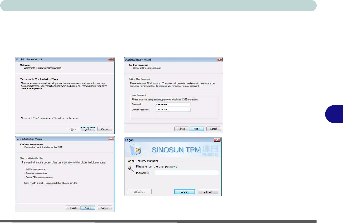
6. Click Next.
7. Type a TPM User Password, and then retype to confirm the password.
8. Click Next > (you may want to add Owner Password Tips) Next to begin the user
initialization process.
9. Click Finish and then enter the user password and click Logon.
Figure 7 - 21
TPM User Initialization
& Logon
Modules & Options
7 - 30 Trusted Platform Module
7
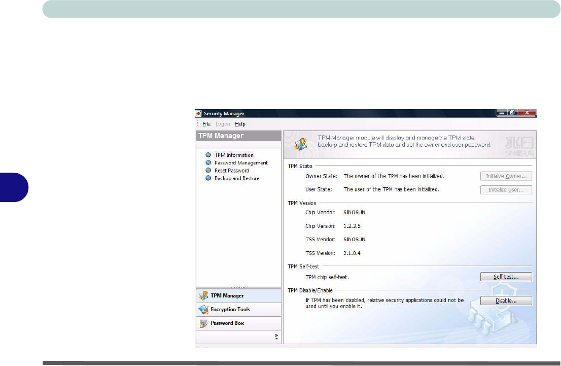
TPM Manager
The TPM Manager allows you to manage and check the TPM state, manage your
password information, and to backup and restore the TPM data. As TPM is usually
administered within large enterprises and organizations, your system administrator
will need to assist you in managing the information in the TPM Manager.
Figure 7 - 22
TPM Manager
(TPM Information)
Modules & Options
Trusted Platform Module 7 - 31
7
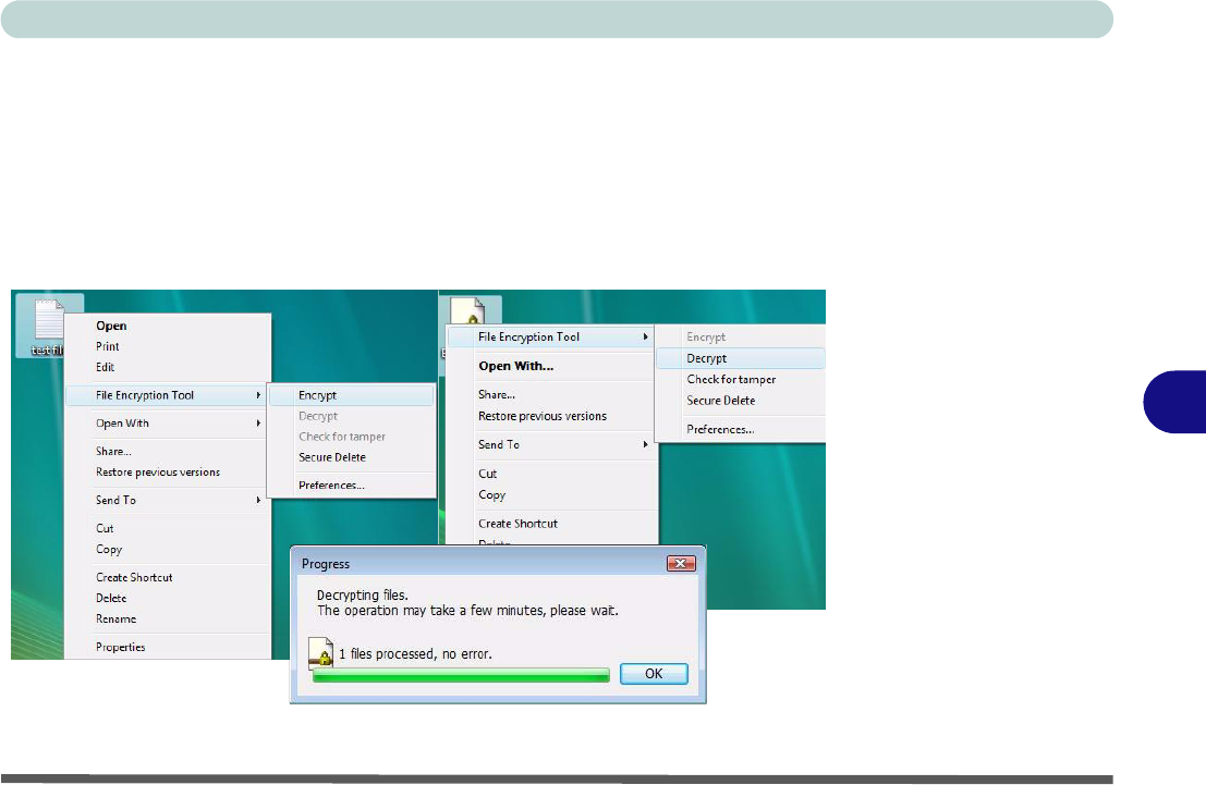
Encrypting/Decrypting a File
You can encrypt and decrypt files from the context menu in Windows.
1. Right-click the file icon to bring up the context menu.
2. Select File Encryption Tool.
3. Select Encrypt/Decrypt.
4. The file will then be encrypted/decrypted.
5. Click OK.
Figure 7 - 23
Encrypting/Decrypting
a File
Modules & Options
7 - 32 Trusted Platform Module
7
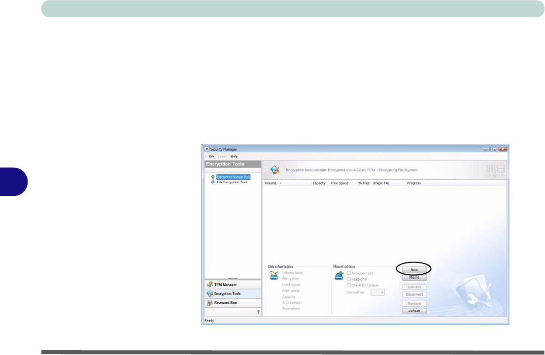
Creating an Encrypted Virtual Disk
You can create an encrypted virtual disk drive (an area of the hard disk you can hide
and mount when required) from the Security Manager application.
1. Run the application from the Security Manager shortcut on the desktop, or from
the TPM Secure Tools item in the Start > Programs/All Programs menu.
2. Click Encryption Tools.
3. Click Encrypted Virtual Disk.
4. Click New.
Figure 7 - 24
Encrypted Virtual Disk
Modules & Options
Trusted Platform Module 7 - 33
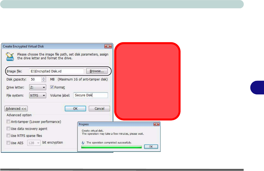
7
5. Type in the Image File name, Volume Label, location (Browse to file location) and
capacity in MB (maximum size is 1GB).
6. Click OK.
7. The disk will now be created.
8. Click OK.
Figure 7 - 25
Create Encrypted
Virtual Disk
Image File
DO NOT lose the image file or
you will be unable to mount
the disk, and this may result in
data loss. It is recommended
that you save the file to remov-
able media such as a USB
Flash drive, and then store it in
a safe location.
Modules & Options
7 - 34 Trusted Platform Module
7
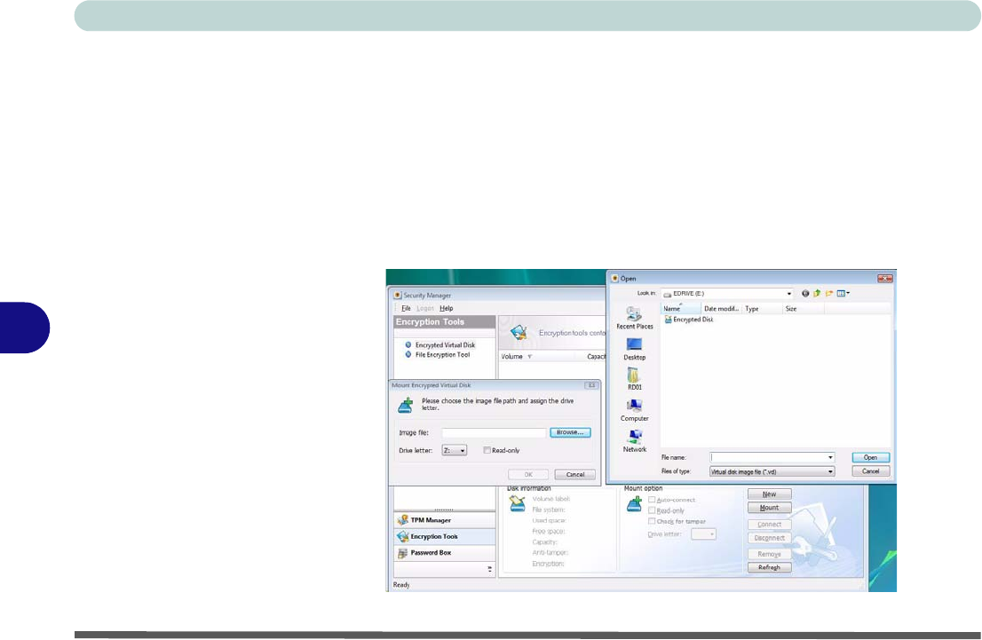
Mounting and Removing an Encrypted Virtual Disk
You can mount and remove the disk using the Security Manager application.
1. Run the application from the Security Manager shortcut on the desktop, or from
the TPM Secure Tools item in the Start > Programs/All Programs menu.
2. Click Encryption Tools.
3. Click Encrypted Virtual Disk.
4. Click Mount to bring up any virtual disk, or click Remove to hide the disk.
5. When mounting a disk you will be asked to browse to the image file.
Figure 7 - 26
Mount Encrypted
Virtual Disk
Modules & Options
Trusted Platform Module 7 - 35
7
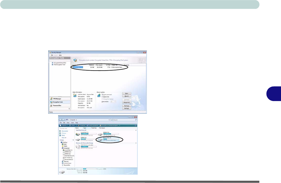
6. Mounting the disk will require the encrypted image file.
7. If you click Disconnect you can hide the disk without the need to browse to the
encrypted image file (simply click Connect to bring up disk again).
8. Clicking Remove will clear the disk information from the menu (the data is still
safe), and you will be required to Mount the disk again to access it (by accessing
the encrypted image file).
Figure 7 - 27
Encrypted Virtual Disk
Modules & Options
7 - 36 Trusted Platform Module
7
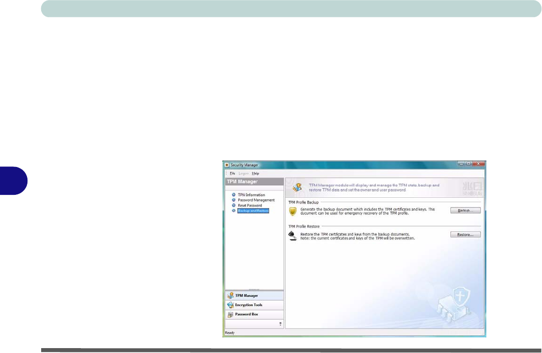
Backing up a TPM Profile
It is recommended that you backup your TPM profile and save it to a safe location
(DO NOT save the file to a virtual disk).
1. Run the application from the Security Manager shortcut on the desktop, or from
the TPM Secure Tools item in the Start > Programs/All Programs menu.
2. Click Backup and Restore.
3. Click Backup > Next.
4. Click Browse.. (button) to save the file to a removable media.
5. Click Next > Next > Finish.
6. The file can be restored from the Backup and Restore menu.
Figure 7 - 28
Backup and Restore
Modules & Options
3.5G Module 7 - 37
7
3.5G Module
If you have included an optional 3.5G module (see “Communication” on page A -
4 for specification details) in your purchase option, you will have the appropriate
software provided for your module. Follow the instructions below to install the
USIM card (which will be provided by your service provider), and then install the
application.
Before installing the application, make sure that the 3.5G module is on. Use the Fn
+ _() key combination (see “Function/Hot Key Indicators” on page 1 - 10) to
toggle power to the 3.5G module. Make sure you install the drivers in the order in-
dicated in Table , on page 4 - 3.
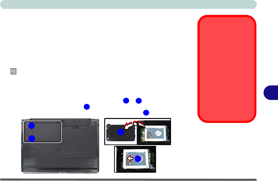
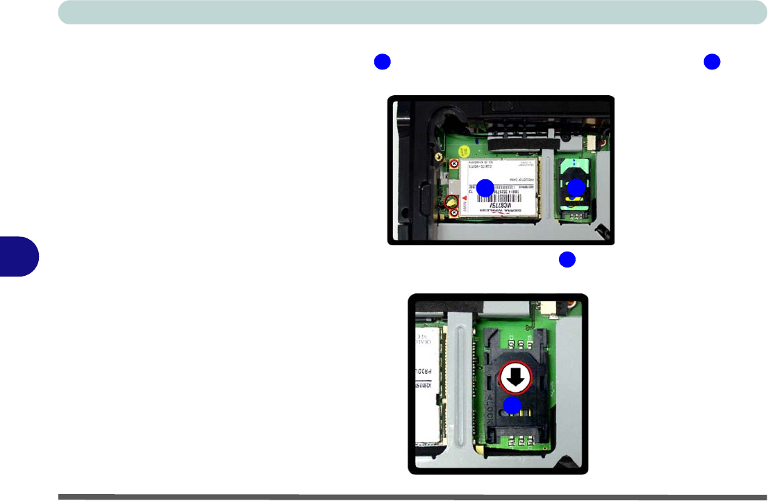
1. Turn off the computer, and turn it over and remove the battery.
2. Locate the hard disk bay cover and loosen screws & .
3. Remove the hard disk bay cover .
4. Grip the tab and slide the hard disk in the direction of arrow to remove it.
Power Safety
Warning
Before you undertake
any installation proce-
dures, make sure that
you have turned off the
power, and disconnect-
ed all peripherals and
cables (including tele-
phone lines). It is advis-
able to also remove your
battery in order to pre-
vent accidentally turning
the machine on.
Figure 7 - 29
Hard Disk Removal
12
34
3
2
1
4
Modules & Options
7 - 38 3.5G Module
7
5. Insert the USIM card as you would into your mobile phone.
6. The 3.5G module is pictured on the left, and the installed USIM card on the
right in Figure 7 - 30.
7. Slide the SIMLOCK in the direction of the arrow (Figure 7 - 31) in order to
release the lock and lift it up.
Figure 7 - 30
Module and USIM
Card Location
Figure 7 - 31
SIMLOCK Unlock
5 6
56
7
7
Modules & Options
3.5G Module 7 - 39
7
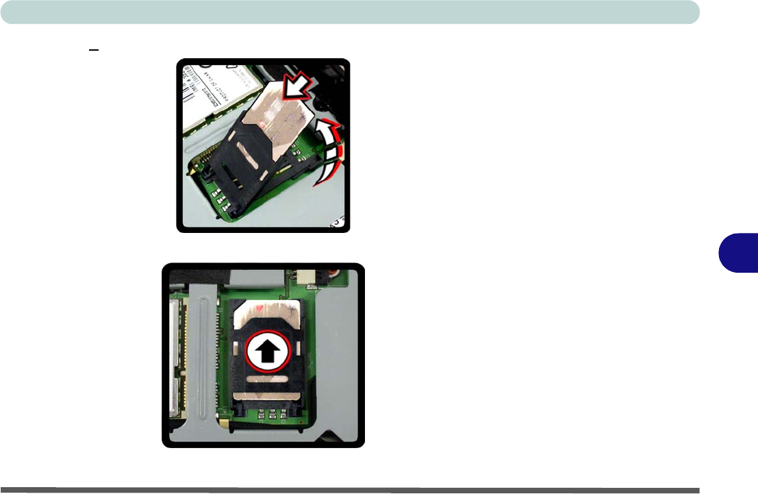
8. Insert the USIM card as illustrated in (Figure 7 - 32) and close the SIMLOCK.
9. Close the SIMLOCK by pushing it in the direction of the arrow in Figure 7 - 33.
10. Replace the hard disk assembly, cover, screws and battery etc.
Figure 7 - 32
Insert the USIM
Card
Figure 7 - 33
SIMLOCK Lock
Modules & Options
7 - 40 3.5G Module
7
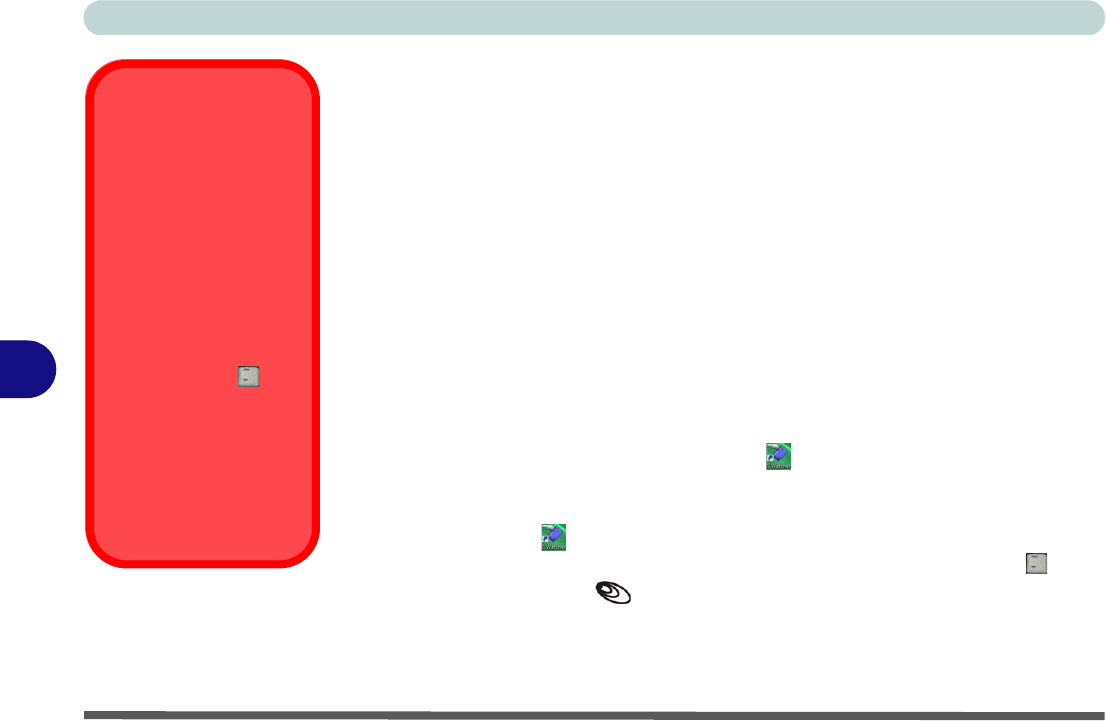
3G Watcher Application
With the 3.5G module and USIM card (provided by your service provider) installed
you may then install the 3G Watcher application. The 3.5G Watcher application al-
lows you to directly access your 3.5G internet service from the computer.
3G Watcher Application Installation
1. Insert the Device Drivers & Utilities + User’s Manual CD-ROM (Win
Vista) into the CD/DVD drive.
2. Click Install Option Drivers (button).
3. Click
4.Install 3G Driver
> Yes
(or
5.Install 3G Driver
if TPM is enabled).
4. Click Next.
5. Choose your region, and click Next.
6. Click the button to accept the license agreement, and then click Next.
7. Click Next > Install.
8. Click Finish, and the 3G Watcher icon will appear on the desktop.
9. You can access the 3G Watcher application from the Start menu (Start >
Programs/All Programs > Sierra Wireless > 3G Watcher), or by clicking
the desktop icon .
10. Make sure you enable power to the module by pressing the Fn + _( ) key
combination (the icon will be green).
Wireless Device
Operation Aboard
Aircraft
The use of any portable
electronic transmission de-
vices aboard aircraft is usu-
ally prohibited. Make sure
the module(s) are OFF if
you are using the computer
aboard aircraft.
Use the Fn + _ () key
combination to toggle pow-
er to the 3.5G module, and
check the indicator to see if
the module is powered on
or not (see Table 1 - 5, on
page 1 - 10/Table 1 - 3, on
page 1 - 7).
Modules & Options
3.5G Module 7 - 41
7
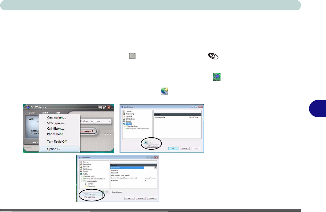
Setting Up a Carrier Profile
Although the connection information is stored on the USIM card supplied by the ser-
vice provider, you will need to set up the appropriate carrier profile from the 3G
Watcher software.
1. Power on the 3.5G module using the Fn + _() key combination (the icon
will be green).
2. Access the 3G Watcher application from the Start menu (Start > Programs/All
Programs > Sierra Wireless > 3G Watcher), or by clicking the desktop icon .
3. Click Tools and select Options.
4. Click Profiles and then click the Add new profile button , and select WWAN
profile.
Figure 7 - 34
Add WWAN Profile
Modules & Options
7 - 42 3.5G Module
7
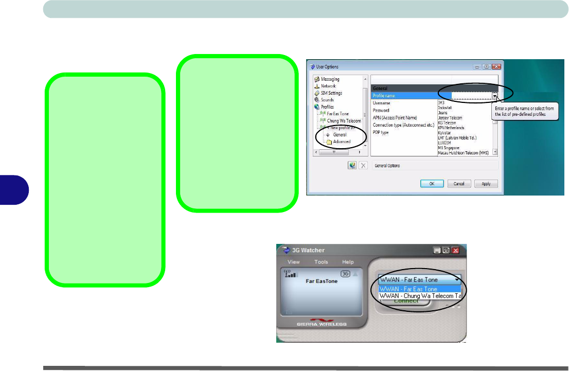
5. You can then enter a new profile name or choose a profile from the drop-down list
provided by the software (see the sidebars for information on the profile details).
6. Click Apply > OK to save the information.
7. You can choose the profile from the pull-down menu.
Figure 7 - 35
User Options
Profile Details
If you have chosen the
profile from the drop-
down list then most of the
information in the
Gener-
al
and
Advanced
tabs
should be automatically
filled in for you (however
check with your service
provider for the latest in-
formation as you may at
least need to add in your
Username
and
Pass-
word
).
Figure 7 - 36
Choose Profile
Profile Information
Click
General
and/or
Ad-
vanced
(and the
sub-
menus
under
Advanced
)
in the left menu, and then
click in any of the fields to
add the appropriate infor-
mation supplied by your
service provider.
Modules & Options
3.5G Module 7 - 43
7
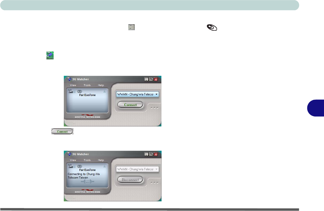
Connecting to the Service Provider
1. Power on the 3.5G module using the Fn + _() key combination (the icon
will be green).
2. You can access the 3G Watcher application from the Start menu (Start >
Programs/All Programs > Sierra Wireless > 3G Watcher), or by clicking the
desktop icon .
3. The software will run and display the service provider name (see “Setting Up a
Carrier Profile” on page 7 - 41).
4. Click Connect to begin the connection process.
5. The 3G Watcher application will then display the connection information in the
window.
Modules & Options
7 - 44 3.5G Module
7
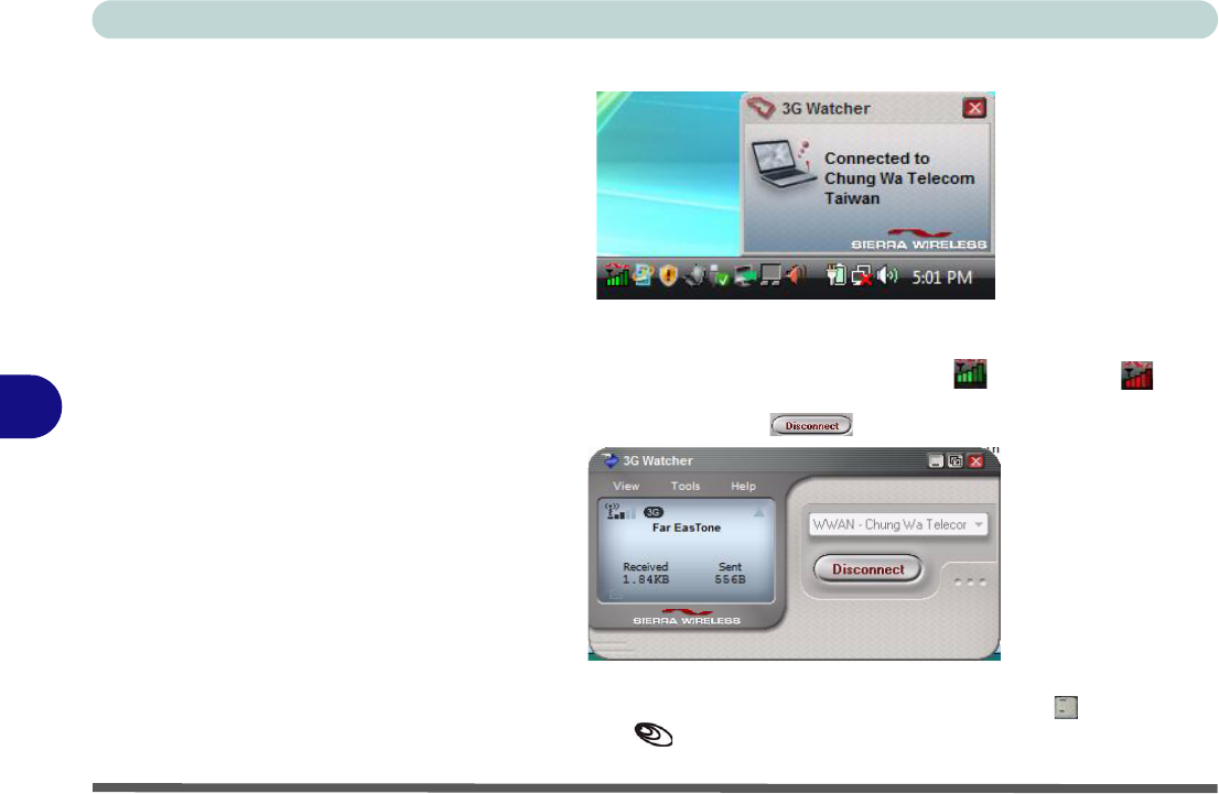
6. When the connection is successful a taskbar notification will appear (as below).
7. You can then access the internet, download e-mail etc. as per any internet
connection.
8. While you are connected the taskbar icon will be green (it will be red when
the program is running but not connected).
9. To disconnect click the Disconnect icon.
10. The program will disconnect from the service provider.
11. The module will still be on, and you will need to press the Fn + _() key
combination (the icon will be off when disconnected).
Figure 7 - 37
Connected
Taskbar
Notification
Figure 7 - 38
3GWatcher
Connected
Modules & Options
3.5G Module 7 - 45
7
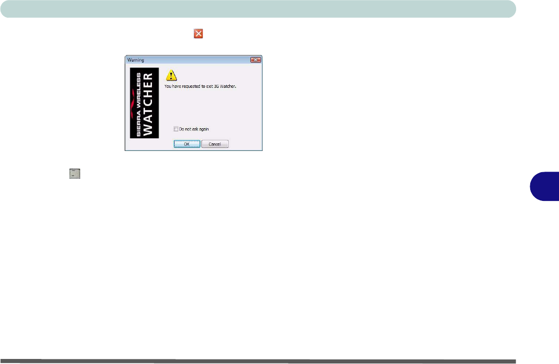
12. If you click the 3G Watcher close icon a message will be displayed asking you
to click OK to confirm the program exit.
13. Exiting the program DOES NOT turn off the 3.5G module, and you will need to press
the
Fn + _
()
key combination to turn off the module (pay careful attention to this
aboard aircraft - see
“Wireless Device Operation Aboard Aircraft” on page 7 - 40
).
14. If the module is on and the computer enters a power-saving state, then the power
status of the module on resuming from the power-saving state will be as below:
• If the 3.5G module is on and the computer is Shut Down; the module will be off
when the computer starts up.
• If the 3.5G module is on and the computer enters Sleep; the module will be on
when the computer resumes from sleep.
• If the 3.5G module is on and the computer enters Hibernate; the module will be
off when the computer starts up.
• If the 3.5G module is on and you Restart the computer; the module will be on
when the computer starts up.
Figure 7 - 39
Exit Warning

Modules & Options
7 - 46 3.5G Module
7
Short Messaging Service
In addition to standard internet services you may also send and receive SMS text
messages using the 3G Watcher program, if your service supports SMS.
Reading SMS Messages
1. The SMS message indicator in the main window will notify you of any new
messages received.
2. Double-click the icon or select Tools > SMS Express.
3. Select the inbox folder and select any message to read it.
4. You cannot receive any new messages if the USIM card becomes full so you will
need to delete some of the messages in order to fee up space on the USIM card.
Creating and Sending SMS Messages
1. Double-click the icon or select Tools > SMS Express.
2. Select File > New Message or click the New button.
3. Enter the recipient’s number in the To.. field or click the To.. button to select an
entry from the phone book, and click the Message button.
4. Type in the message details in the message body area.
5. Click the Send button (or save the message to send later).
For more details on SMS see 3GWatcher Online Help from the Help > Help Top-
ics menu.

Troubleshooting
Overview 8 - 1
8
Chapter 8: Troubleshooting
Overview
Should you have any problems with your computer, before consulting your service representative, you may want
to try to solve the problem yourself. This chapter lists some common problems and their possible solutions. This
can’t anticipate every problem, but you should check here before you panic. If you don’t find the answer in these
pages, make sure you have followed the instructions carefully and observed the safety precautions in the preface.
If all else fails, talk to your service representative. You should also make a record of what happened and what
remedies you tried.
Of course, if something goes wrong, it will happen at the most inconvenient time possible, so you should preview
this section just in case. If, after you’ve tried everything, and the system still won’t cooperate, try turning it off
for a few minutes and then rebooting. You will lose any unsaved data, but it may start working again. Then call
your service representative.

Troubleshooting
8 - 2 Basic Hints and Tips
8
Basic Hints and Tips
Many of the following may seem obvious but they are often the solution to a problem when your computer ap-
pears not to be working.
•Power - Is the computer actually plugged into a working electrical outlet? If plugged into a power strip,
make sure it is actually working. Check the LED Power & Communication Indicators (see “LED Indica-
tors” on page 1 - 7) to see the computer’s power status.
•Connections - Check all the cables to make sure that there are no loose connections anywhere.
•Power Savings - Make sure that the system is not in Hibernate or Sleep mode by pressing the keys config-
ured in your Power Options (see “Power-Saving States” on page 3 - 6), the Fn + F4 key combination, or
power button to wake-up the system.
•Brightness - Check the brightness of the screen by pressing the Fn + F8 and F9 keys to adjust the bright-
ness.
•Display Choice - Press Fn + F7 to make sure the system is not set to “external only” display.
•Boot Drive - Make sure there are no optical media and/or USB storage devices in any connected drive
(this is a common cause of the message “Invalid system disk - Replace the disk, and then press any key” /
“Remove disks or other media. Press any key to restart”).

Troubleshooting
Backup and General Maintenance 8 - 3
8
Backup and General Maintenance
•Always backup your important data, and keep copies of your OS and programs safe, but close to hand.
Don’t forget to note the serial numbers if you are storing them out of their original cases, e.g. in a CD wal-
let.
• Run maintenance programs on your hard disk and OS as often as you can. You may schedule these pro-
grams to run at times when you are not using your computer. You can use those that are provided free with
your OS, or buy the more powerful dedicated programs to do so.
• Write down your passwords and keep them safe (away from your computer). This is especially important if
you choose to use a Supervisor password for the BIOS (see “The Power-On Self Test (POST)” on page 5 -
2).
• Keep copies of vital settings files such as network, dialup settings, mail settings etc.(even if just brief notes).
Warranty
The CPU is not a user serviceable part. Opening this compartment, or accessing the CPU in any way, may violate your war-
ranty.

Troubleshooting
8 - 4 Viruses
8
Viruses
• Install an Anti-Virus program and keep the definitions file (the file which tells your program which viruses
to look for) up to date. New computer viruses are discovered daily, and some of them may seriously harm
your computer and cause you to lose data. Anti-Virus programs are commercially available and the defini-
tions file updates are usually downloadable directly from the internet.
• Be careful when opening e-mail from sources you don’t know. Viruses are often triggered from within e-
mail attachments so take care when opening any attached file. You can configure most Anti-Virus pro-
grams to check all e-mail attachments. Note: You should also beware of files from people you know as the
virus may have infected an address book and been automatically forwarded without the person’s knowl-
edge.
• Keep a “Bootable CD-ROM/DVD-ROM/USB storage device” (this CD/DVD/USB device provides basic
information which allows you to startup your computer) handy. You may refer to your OS’s documentation
for instructions on how to make one, and many Anti-Virus programs will also provide such a disk (or at
least instructions on how to make one).

Troubleshooting
Upgrading and Adding New Hardware/Software 8 - 5
8
Upgrading and Adding New Hardware/Software
• Do not be tempted to make changes to your Windows Registry unless you are very sure of what you are
doing, otherwise you will risk severely damaging your system.
• Don’t open your computer or undertake any repair or upgrade work if you are not comfortable with what
you are doing.
• Read the documentation. We can assume, since you are reading this that you are looking at the computer’s
manual, but what about any new peripheral devices you have just purchased? Many problems are caused by
the installation of new hardware and/or software. Always refer to the documentation of any new hardware
and/or software, and pay particular attention to files entitled “READ ME” or “READ ME FIRST”.
• When installing a new device always make sure the device is powered on, and in many cases you will need
to restart the computer. Always check that all the cables are correctly connected.
• Make sure you have installed the drivers for any new hardware you have installed (latest driver files are
usually available to download from vendor’s websites).

Troubleshooting
8 - 6 Upgrading and Adding New Hardware/Software
8
• Thoroughly check any recent changes you made to your system as these changes may affect one or more
system components, or software programs. If possible, go back and undo the change you just made and see
if the problem still occurs.
• Don’t over complicate things. The less you have to deal with then the easier the source of the problem may
be found; Example - if your computer has many devices plugged into its ports, and a number of programs
running, then it will be difficult to determine the cause of a problem. Try disconnecting all of the devices and
restarting the computer with all the peripheral devices unplugged. A process of elimination (adding and
removing devices and restarting where necessary) will often find the source of a problem, although this may
be time consuming.
Troubleshooting
Problems and Possible Solutions 8 - 7
8
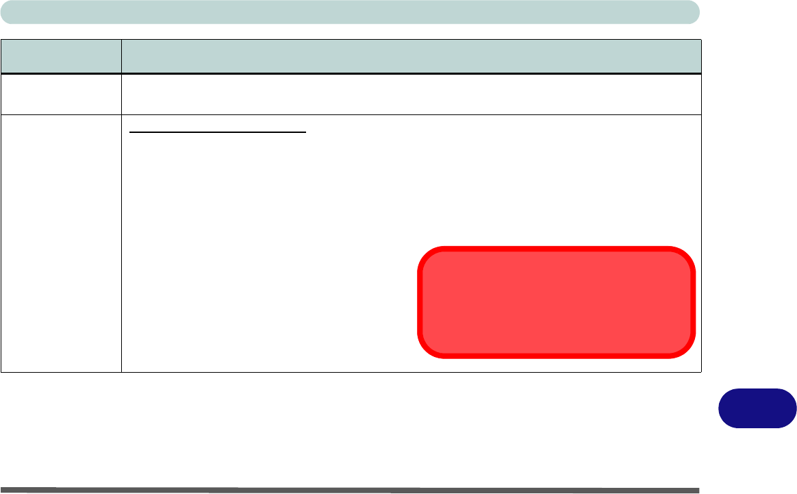
Problems and Possible Solutions
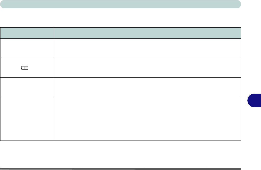
Problem Possible Cause - Solution
You turned on the power
but it doesn’t work.
Battery missing / incorrectly installed. Check the battery bay, make sure the battery is present
and seated properly (the design of the battery only allows it to go in one way). Make sure there’s
nothing interfering with the battery contacts.
The battery LED power
indicator , is blinking
orange.
Low Battery. Plug in the DC power source. If the computer doesn’t start up immediately, turn it off
then on again.
You are losing battery
power too quickly.
The system is using too much power. If your OS has a Power Options scheme (see “Power
Plans” on page 3 - 4/“Power Schemes” on page D - 18) check its settings. You may also be
using an ExpressCard/USB device/external device that is drawing a lot of power.
Actual battery operating
time is shorter than
expected.
The battery has not been fully discharged before being recharged. Make sure the battery is fully
discharged and recharge it completely before reusing (see “Battery Information” on page 3 -
10/“Battery Information” on page D - 23).
Power Options have been disabled. Go to the Control Panel in Windows and re-enable the
options.
A peripheral device/USB device/ExpressCard is consuming a lot of power. Turn off/remove the
unused device to save power.

Troubleshooting
8 - 8 Problems and Possible Solutions
8
The computer feels too
hot.
Make sure the computer is properly ventilated and the Vent/Fan intakes are not blocked. If this
doesn’t cool it down, put the system into Hibernate mode or turn it off for an hour. Make sure the
computer isn’t sitting on a thermal surface (see “Overheating” on page 1 - 14). Make sure
you’re using the correct adapter.
Make sure that your notebook is completely powered off before putting it into a travel bag (or any
such container). Putting a notebook which is powered on in a travel bag may cause the Vent/Fan
intakes to be blocked.
Nothing appears on
screen.
The system is in a power saving mode. Toggle the sleep/resume key combination, Fn + F4 (see
“Configuring the Power Buttons” on page 3 - 8/“Configuring the Power Button” on page D
- 22).
The screen controls need to be adjusted. Toggle the screen control key combinations Fn + F8/F9.
If you’re connected to an external monitor, make sure it’s plugged in and turned on. You should
also check the monitor’s own brightness and contrast controls.
The computer is set for a different display. Toggle the screen display key combination, Fn + F7. If
an external monitor is connected, turn it on.
The screen saver is activated. Press any key or touch the TouchPad.
No image appears on the
external monitor I have
plugged in and powered
on.
You haven’t installed the video driver and configured it appropriately from the Control Panel. See
Appendix B/“Video Features” on page D - 7 for instructions on installing and configuring the
video driver.
Problem Possible Cause - Solution

Troubleshooting
Problems and Possible Solutions 8 - 9
8
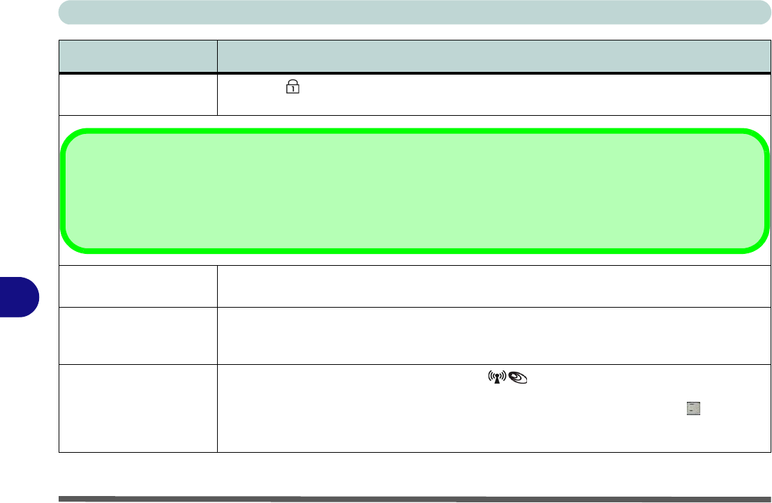
You forget the boot
password.
If you forget the password, you may have to discharge the battery of the CMOS. Contact your
service representative for help.
The sound cannot be
heard or the volume is
very low.
The volume might be set too low. Check the volume control in the Volume Control Panel in the
Windows taskbar, or use the key combination Fn + F5 and F6 (see “Function/Hot Key
Indicators” on page 1 - 10) to adjust.
The CD/DVD cannot be
read.
The CD/DVD is dirty. Clean it with a CD/DVD cleaner kit.
The CD/DVD tray will
not open when there is a
disc in the tray.
The CD/DVD is not correctly placed in the tray. Gently try to remove the disc using the eject hole
(see “Loading Discs” on page 2 - 3).
The DVD regional
codes can no longer be
changed.
The code has been changed the maximum 5 times. See “DVD Regional Codes” on page 2 - 5/
“DVD Regional Codes” on page D - 2.
Problem Possible Cause - Solution
Password Warning
If you choose to set a boot password, NEVER forget your password. The consequences of this could be serious. If you cannot
remember your boot password you must contact your vendor and you may lose all of the information on your hard disk.
Troubleshooting
8 - 10 Problems and Possible Solutions
8
Unwelcome numbers
appear when typing.
If the LED is lit, then Num Lock is turned ON. (see “LED Indicators” on page 1 - 7).
The system freezes or
the screen goes dark.
The system’s power saving features have timed-out. Use the AC/DC adapter, press the sleep (Fn
+ F4) key combination, or press the power button if no LEDs are lit.
The system never goes
into a power saving
mode.
Power Options features are not enabled. Go to the Windows Power Options menu and enable
the features you prefer (see “Power-Saving States” on page 3 - 6/“System Power Options”
on page D - 20). Make sure you have enabled Hibernate mode from the control panel.
The Wireless LAN/
Bluetooth/3.5G modules
cannot be detected.
The modules are off. Check the LED indicator and/or function key indicator to see if the
WLAN/Bluetooth/3.5G module is on or off (see “LED Indicators” on page 1 - 7). If the LED
indicator is off, then press the Fn + F11 (WLAN), Fn + F12 (Bluetooth) or Fn + _ (3.5G) key
combination(s) in order to enable the modules (see “Function/Hot Key Indicators” on page 1 -
10).
Problem Possible Cause - Solution
Other Keyboards
If your keyboard is damaged or you just want to make a change, you can use any standard USB keyboard. The system will
detect and enable it automatically. However special functions/hot keys unique to the system’s regular keyboard may not
work.

Troubleshooting
Problems and Possible Solutions 8 - 11
8
The PC Camera module
cannot be detected.
The module is off. Press the Fn + F10 key combination in order to enable the module (see
“Function/Hot Key Indicators” on page 1 - 10). Run the BisonCap/Video View program to
view the camera picture.
The Wireless LAN/
Bluetooth/ PC Camera/
3.5G modules cannot be
configured.
The driver(s) for the module(s) have not been installed. Make sure you have installed the driver
for the appropriate module (see the instructions for the appropriate module in “Modules &
Options” on page 7 - 1/“Module Drivers” on page D - 31).
Problem Possible Cause - Solution

Troubleshooting
8-12
8

Interface (Ports & Jacks)
Interface (Ports & Jacks) A - 1
A
Appendix A: Interface (Ports & Jacks)
Overview
The following chapter will give a quick description of the interface (ports & jacks) which allow your computer
to communicate with external devices, connect to the internet etc.
Interface (Ports & Jacks)
A - 2 Interface (Ports & Jacks)
A
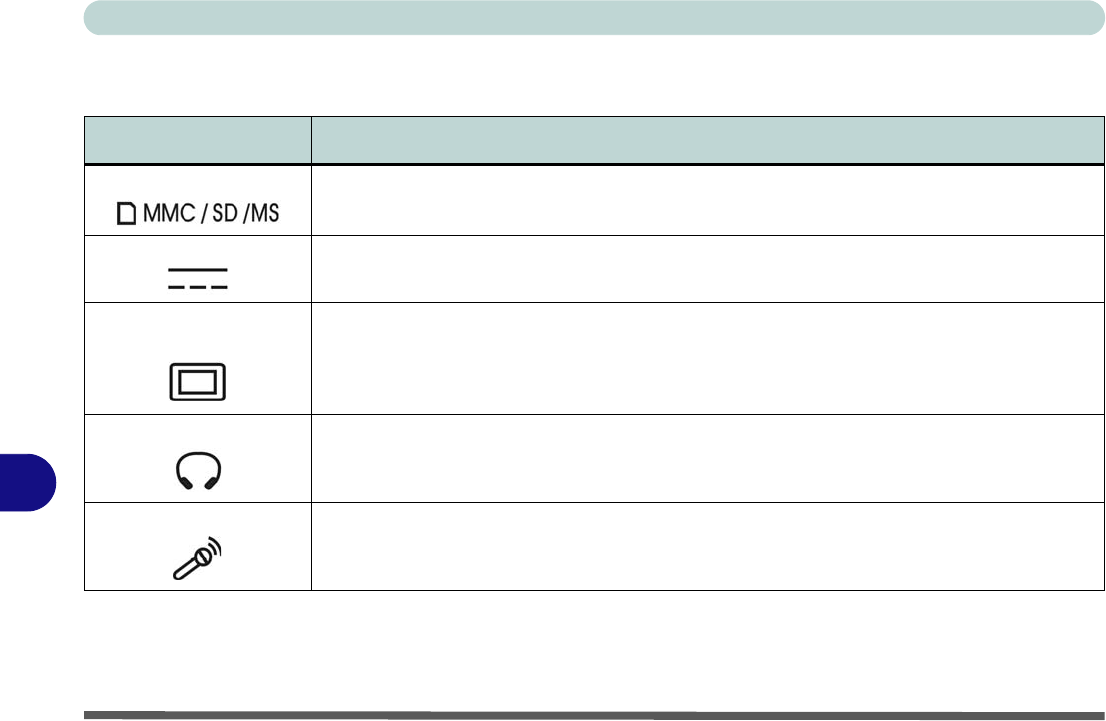
Notebook Ports and Jacks
Item Description
Card Reader Port The card reader allows you to use some of the latest digital storage cards. Push the card into the
slot and it will appear as a removable device.
DC-In Jack Plug the supplied AC/DC adapter into this jack to power your computer.
External Monitor (VGA)
Port
This port allows you to connect an external monitor, or Flat Panel Display, to get dual video or
simultaneous display on the LCD and external monitor/FPD.
Headphone-Out Jack Headphones or speakers may be connected through this jack. Note: Set your system’s volume to
a reduced level before connecting to this jack.
Microphone-In Jack Plug an external microphone in to this jack to record on your computer.
Interface (Ports & Jacks)
Interface (Ports & Jacks) A - 3
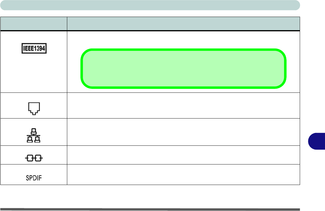
A
Mini-IEEE 1394 Port This port allows a high-speed connection to various peripheral devices, e.g. external disk drives
and digital cameras (see note below).
RJ-11 Modem Jack This port connects to the built-in modem. You may plug the telephone line directly into this RJ-11
telephone connection.
Note: Broadband (e.g. ADSL) modems usually connect to the LAN port.
RJ-45 LAN Jack This port supports LAN (Network) functions.
Note: Broadband (e.g. ADSL) modems usually connect to the LAN port.
Security Lock Slot To prevent possible theft, a Kensington-type lock can be attached to this slot. Locks can be
purchased at any computer store.
S/PDIF-Out Jack This S/PDIF (Sony/Philips Digital Interface Format) Out Jack allows you to connect your DVD-
capable PC to a Dolby AC-3 compatible receiver for “5.1” or ‘dts’ surround sound.
Item Description
Mini-IEEE 1394 Port
The Mini-IEEE 1394 port only supports SELF POWERED IEEE 1394 devices.

Interface (Ports & Jacks)
A-4
A
USB 2.0/1.1 Ports These USB 2.0 compatible ports (USB 2.0 is fully USB 1.1 compliant) are for low-speed
peripherals such as keyboards, mice or scanners, and for high-speed peripherals such as
external HDDs, digital video cameras or high-speed scanners etc. Devices can be plugged into
the computer, and unplugged from the computer, without the need to turn the system off (if the
power rating of your USB device is 500mA or above, make sure you use the power supply which
comes with the device).
Item Description

Intel Video Driver Controls
Intel Video Driver Installation B - 1
B
Appendix B: Intel Video Driver Controls
The basic settings for configuring the LCD are outlined in “Video Features” on
page 1 - 16.
Intel Video Driver Installation
Make sure you install all the drivers in the order indicated in
Table 4 - 1, on page 4 - 3
.
Video
1. Insert the Device Drivers & Utilities + User’s Manual CD-ROM (Win
Vista) into the CD/DVD drive.
2. Click Install Vista Drivers.
1. Click 1.Install Video Driver > Yes.
2. Click Next > Yes > Next > Next.
3. Click Finish to restart the computer.
Dynamic Video Memory Technology
Intel® DVMT automatically and dynamically allocates as much system memory
(RAM) as needed to the video system (the video driver must be installed). DVMT
returns whatever memory is no longer needed to the operating system. To adjust the
total video memory used by the computer (Pre-Allocated + Fixed + DVMT) see
“Total Graphics Memory: (Advanced Menu)” on page 5 - 9.
DVMT Notes
DVMT is not local video
memory.
DVMT will not function
in MS-DOS. DOS uses
the legacy memory indi-
cated.
Intel Video Driver Controls
B - 2 Intel Graphics Properties
B
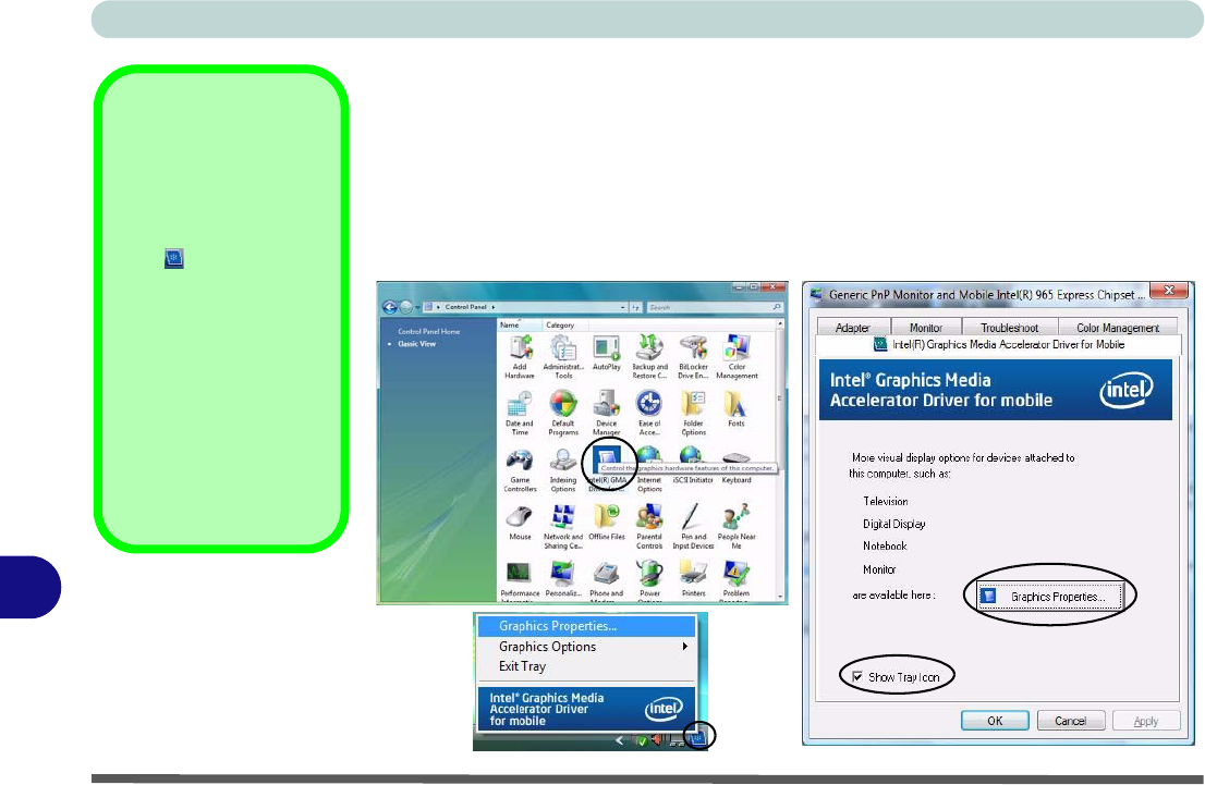
Intel Graphics Properties
More advanced video configuration options are provided by the Intel(R) Graphics
Media Accelerator Driver for Mobile.
1. Open the Display Settings control panel (see “Video Features” on page 1 - 16)
and click Advanced Settings (button).
2. Click the Intel(R)... tab and click Graphics Properties (button).
Taskbar Icon
The Intel GMA control
panel can also be ac-
cessed by clicking the
icon in the taskbar
and selecting Graphics
Properties from the
menu.
If you cannot see the
tray icon click the “Show
Tray Icon” tickbox in the
Intel(R) Graphics Me-
dia Accelerator for Mo-
bile tab.
Figure B - 1
Intel Graphics
Properties
Intel Video Driver Controls
Intel Graphics Properties B - 3
B
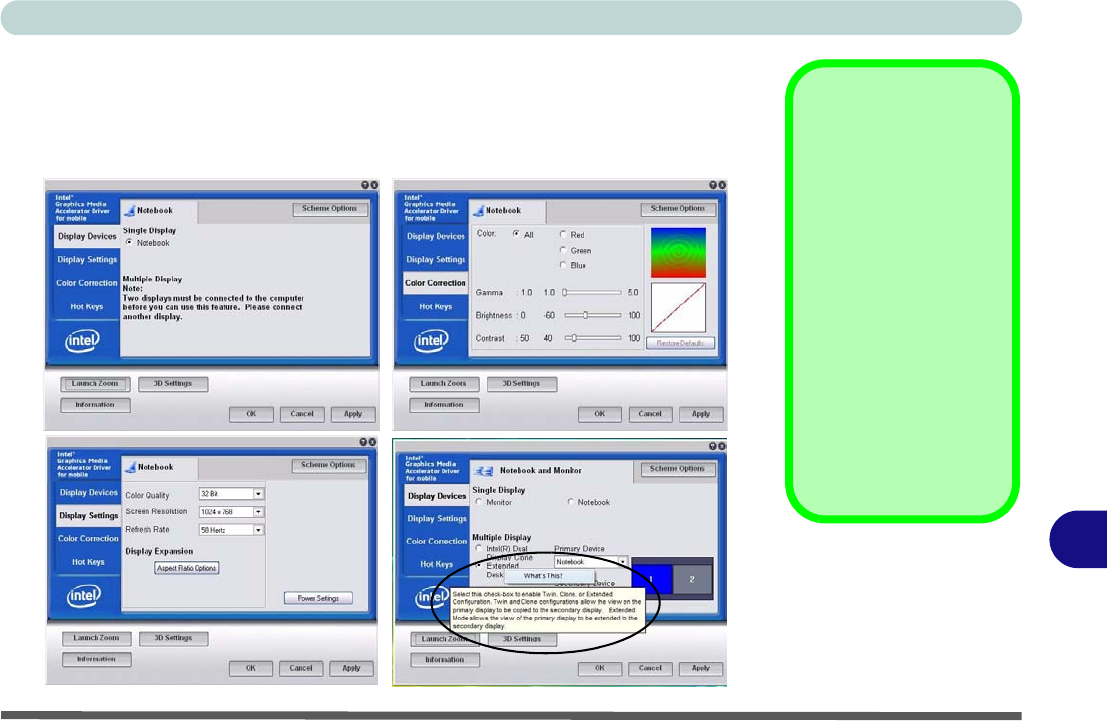
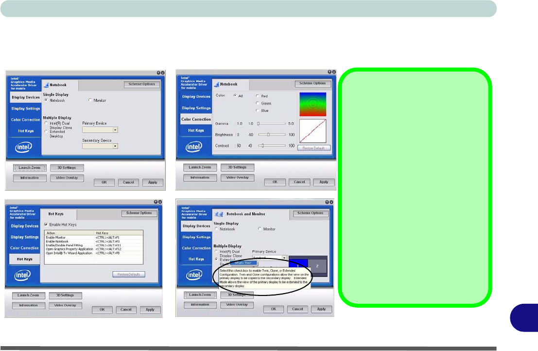
You may make changes to the devices, color, schemes, Hot Keys etc. by clicking
the appropriate menu item or button. Click Information (button) to obtain useful in-
formation about the graphics properties of the computer, and see the Support tab in
Information to get weblinks to the latest information on the Intel Website.
Help Menus
Right-click on many of
the items in the tabs to
bring up the “What’s
This?” button.
Click the “What’s This?”
button to bring up the
help menu.
Multiple Display
At least one other dis-
play must be attached in
order to view Multiple
Display options.
Figure B - 2
Intel Graphics Media
Accelerator Driver
for mobile
(Control Panel Tabs)
Intel Video Driver Controls
B - 4 Intel Graphics Properties
B
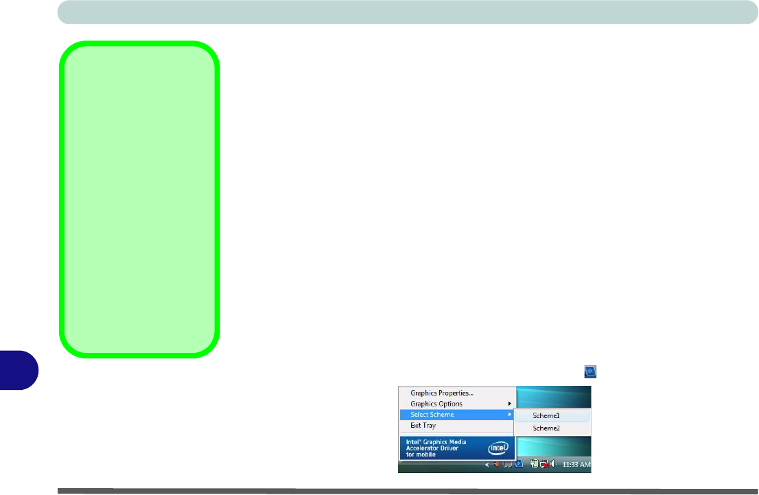
Scheme Options
Use Scheme Options to configure quick settings for applications which require spe-
cific resolution and color settings in order to run properly e.g. games, multimedia
programs. To set the scheme options:
1. Open the Display Settings control panel and click Advanced Settings (button).
2. Click the Intel(R)... tab and click Graphics Properties (button).
3. Configure your display configuration, resolution etc. as per your requirements from
Display Settings.
4. Click on Scheme Options (button).
5. Type a name for the scheme then click Save.
6. If you want to automatically launch an application when running the scheme click
on Browse (button).
7. Browse to the executable file for the application you want to set the scheme for
(see sidebar), and click Open to select it.
8. Click Save (Save > OK) to save the settings (you can click in the "Restore the
display settings after exiting this application" box to return to your original
settings when you exit the program).
9. Click OK to exit the window.
10. You can run the scheme by clicking the taskbar icon and selecting the scheme
from Select Scheme.
Application.exe
You will need to locate
the actual application
executable (.exe) file,
not just the shortcut. To
find the application right-
click its shortcut on the
desktop click Proper-
ties. Click the Shortcut
(tab) and see where the
executable file is located
by clicking the Find Tar-
get (button). Note the lo-
cation and you will then
be able to browse to this
file.
Figure B - 3
Select Scheme
Intel Video Driver Controls
Attaching Other Displays B - 5
B
Attaching Other Displays
Besides the built-in LCD, you can also use an external monitor/flat panel display,
connected to the external monitor port at the rear of the computer, as your display
device. The following are the display options:
1. The built-in LCD OR an external monitor/flat panel display connected to the exter-
nal monitor port (Single Display).
2. The built-in LCD AND an external monitor/flat panel display connected to the
external monitor port (Multiple Display).
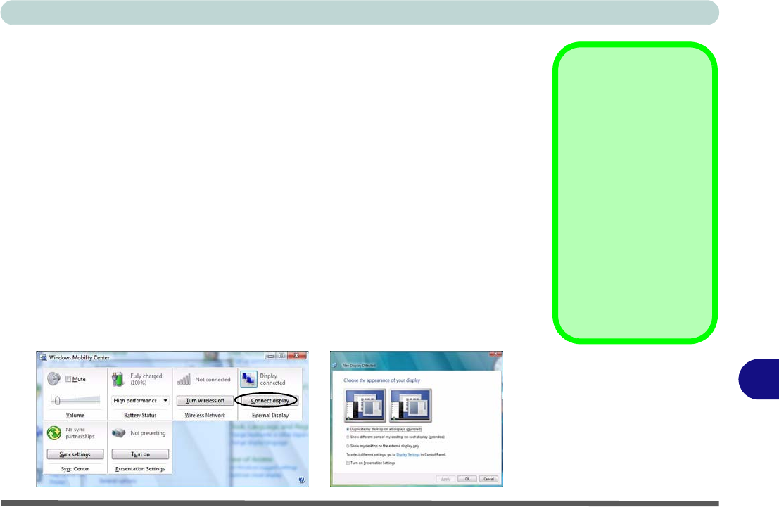
Configuring from Windows Vista
1. Attach your external display to the external monitor port, and turn it on.
2. If a New Display Detected window does not appear in Windows Vista, go to the
Windows Mobility Center control panel (Mobile PC > Adjust commonly used
mobility settings) and click Connect display.
3. Click on any of the buttons to configure the displays to your preference, or click
Display Settings to access the control panel.
Function Key
Combination
You can use the Fn + F7
key combination to tog-
gle through the display
options:
• Notebook Only
• External Display Only
• Notebook + External
Display
Make sure you give the
displays enough time to
refresh.
Intel Video Driver Controls
B - 6 Attaching Other Displays
B
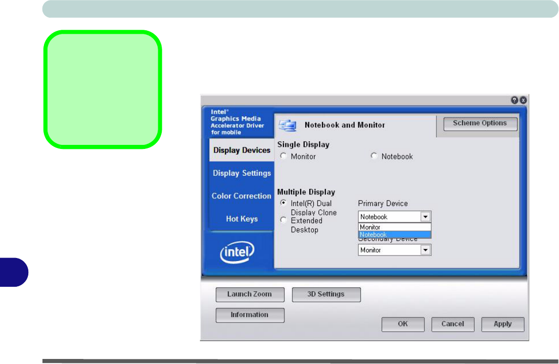
Configuring from Intel® GMA Driver for Mobile
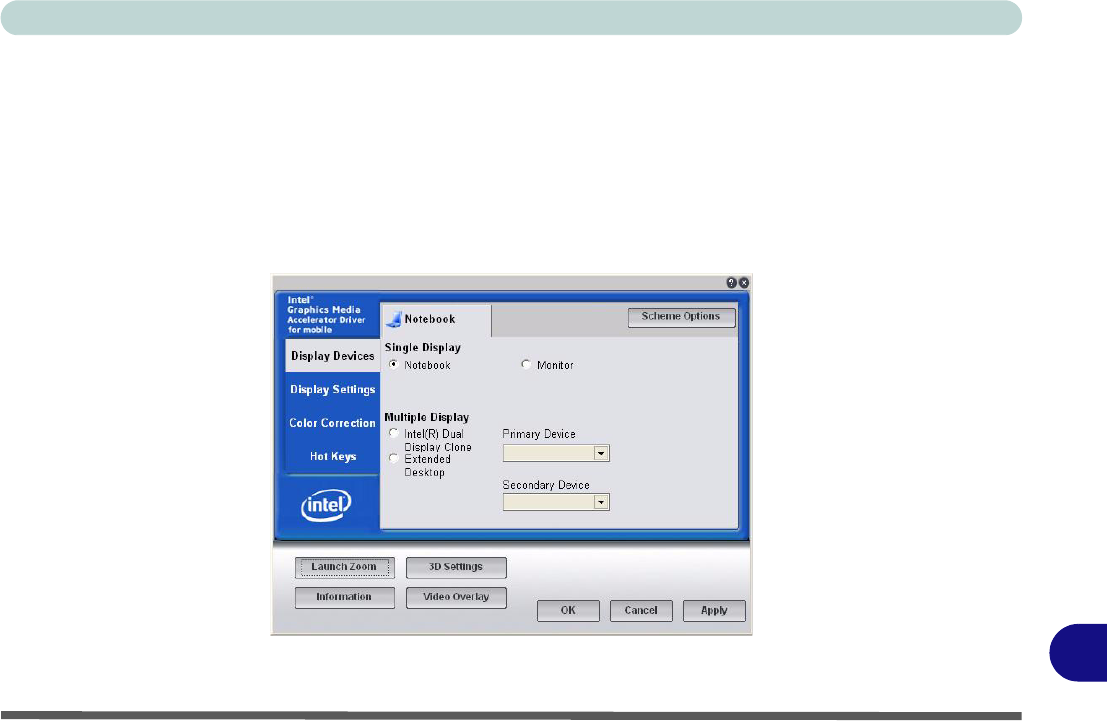
1. Go to the Intel Graphics Properties control panel (see “Intel Graphics Proper-
ties” on page B - 2) and click Display Devices.
2. Click to choose the display option from the Multiple Display menu.
3. Click Apply (and OK to confirm the settings change) and OK (button).
Multiple Display
At least one other dis-
play must be attached in
order to view Multiple
Display options.
Figure B - 4
Display Devices

Intel Video Driver Controls
Display Modes B - 7
B
Display Modes
Single Display
Only one of your attached displays is used.
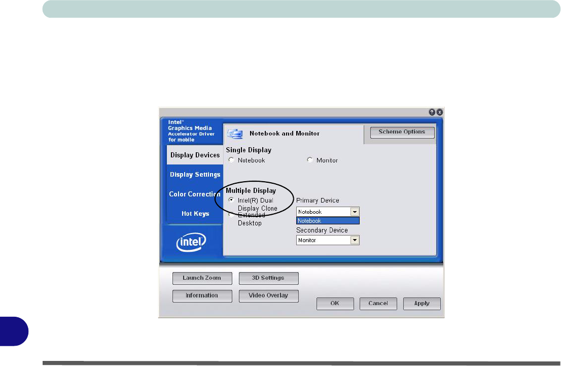
Intel(R) Dual Display Clone (mirrored)
This mode will drive multiple displays with the same content. Each device may be
configured independently for different resolutions, refresh rates, color quality etc.
Use this feature to display the screen through a projector for a presentation.
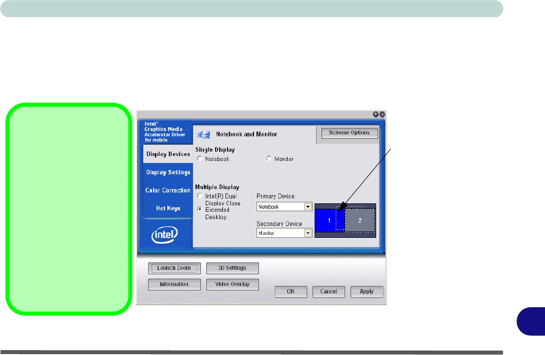
Extended Desktop (extended)
This mode allows a desktop to span multiple displays and acts as a large workspace.
This creates a lot more screen area for display. Use the Display Properties control
panel to drag the monitors to match the physical arrangement you wish to use, or you
may also use the Extended Desktop Settings control panel tab in Graphics Prop-
erties to configure the relative size and position.
Intel Video Driver Controls
B - 8 Display Modes
B
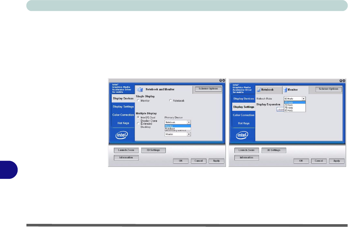
To Enable Intel(R) Dual Display Clone
1. Attach your external monitor to the external monitor port, and turn it on.
2. Go to the Intel Graphics Properties control panel (see “Intel Graphics
Properties” on page B - 2) and click Display Devices.
3. Click to choose Intel(R) Dual Display Clone (Multiple Display).
4. Click Apply, and OK to confirm the settings change.
5. Click Display Settings to adjust the settings for the attached devices.
Figure B - 5
Display Devices &
Settings
Intel Video Driver Controls
Display Modes B - 9
B
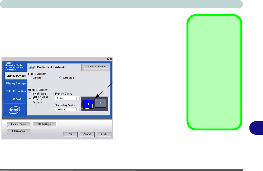
To Enable Extended Desktop
1. Attach your external monitor to the external monitor port, and turn it on.
2. Go to the Intel Graphics Properties control panel (see “Intel Graphics
Properties” on page B - 2) and click Display Devices.
3. Click to choose Extended Desktop (Multiple Display).
4. Click Apply, and OK to confirm the settings change.
5. Click Display Settings to adjust the settings for the attached devices.
Display Settings
Extended Desktop
You can have different
Colors, Screen Area
and Monitor Refresh
Rates for each display
device provided your
monitor can support
them.
You can drag the moni-
tor icons to match the
physical layout of your
displays. Icons and pro-
grams may also be
dragged between the
displays.
Figure B - 6
Extended Desktop
Mode
Click the appropriate moni-
tor icon and drag it to match
the physical arrangement
you wish to use (e.g. the
secondary display may be
extended left/right/above/
below the primary display).
Click Display Settings to
make any adjustments re-
quired.
Intel Video Driver Controls
B - 10 Display Modes
B
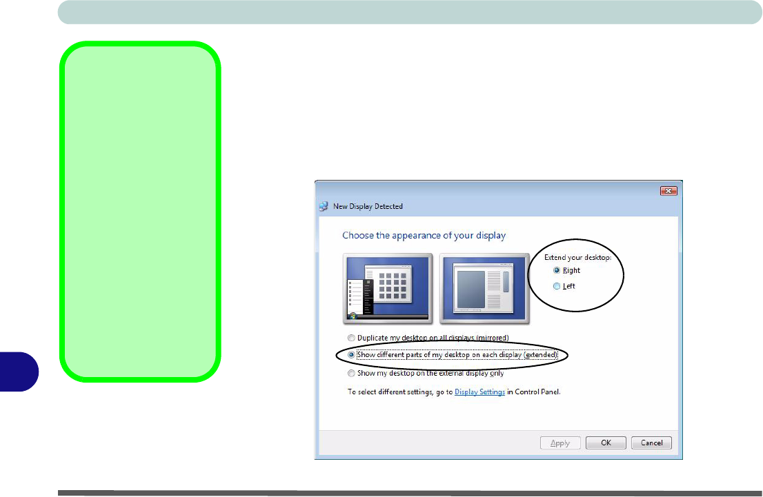
Using Windows Vista to Enable Extended Mode
1. Attach your external display to the external monitor port, and turn it on.
2. If a New Display Detected window does not appear in Windows Vista, go to the
Windows Mobility Center control panel (Mobile PC > Adjust commonly used
mobility settings) and click Connect display.
3. Click to select Show different parts of my desktop on each display (extended).
4. Click Right or Left under Extend your desktop.
5. Click Apply > OK.
Display Settings
Extended Desktop
Use the control panel to
drag the monitors to
match the physical ar-
rangement you wish to
use.
You can drag any icons
or windows across to ei-
ther display desktop,
which makes it possible
to have one program
visible in one of the dis-
plays, and a different
program visible in the
other display.
Figure B - 7
Display Properties
(Extended Desktop)
Intel Video Driver Controls
Display Modes B - 11
B
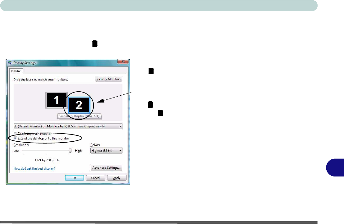
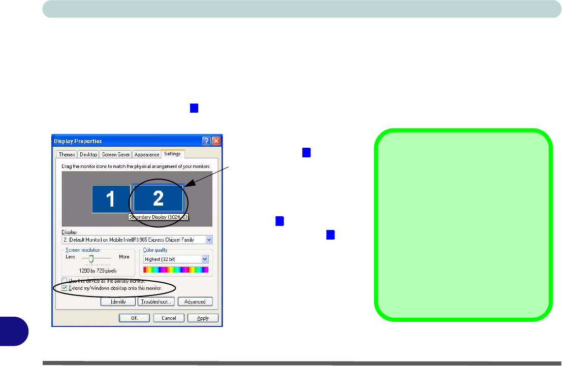
Using Display Settings to Enable Extended Mode
1. Attach your external display to the external monitor port, and turn it on.
2. Open the Display Settings control panel (see “Video Features” on page 1 - 16).
3. Click the monitor icon (e.g. ), and make sure you have checked “Extend my
Windows desktop onto this monitor.” and click Apply.
Figure B - 8
Display Properties
(Extended Desktop)
2
Click the appropriate monitor icon
(e.g. ) to be able to select the op-
tion to extend the desktop on to it.
In this example the Primary Dis-
play is on the left, the Secondary
Display is on the right.
2
1
2

Intel Video Driver Controls
B-12
B

Specifications
Specifications C - 1
C
Appendix C: Specifications
Latest Specification Information
The specifications listed in this Appendix are correct at the time of going to press. Certain items (particularly processor types/
speeds and CD/DVD device types) may be changed, delayed or updated due to the manufacturer's release schedule. Check
with your service center for details.

Specifications
C - 2 Specifications
C
Feature Specification
Processor Intel® Core™2 Duo Processor
(478-pin) Micro-FC-PGA Package - Socket-P
T7100
65nm (65 Nanometer) Process Technology
2MB On-die L2 Cache & 800MHz FSB
1.8 GHz
Intel® Core™2 Duo Processor
(478-pin) Micro-FC-PGA Package - Socket-P
T7300/ T7500/ T7700
65nm (65 Nanometer) Process Technology
4MB On-die L2 Cache & 800MHz FSB
2.0/ 2.2/ 2.4 GHz
Core Logic Intel GM965+ICH8M Chipset
LCD 12.1" WXGA (1280 * 800) Glare / Non Glare TFT LCD
Memory Dual Channel 64-bit Wide DDRII (DDR2)
Two 200 Pin SO-DIMM Sockets Supporting DDRII (DDR2) 533MHz - 512MB RAM Modules OR
667MHz - 512MB/1024MB RAM Modules
Memory Expandable up to 2GB (512/1024 MB DDRII Modules)
Video Adapter Intel GM965 Integrated Video
High Preference 3D/2D Graphic Accelerator
Supports Dynamic Video Memory Technology DVMT (up to 256MB dynamically allocated from system
memory where needed)
Supports DirectX 9 3D Graphics Engine Accelerator
Security Security (Kensington® Type) Lock Slot
Fingerprint ID Reader Module (Factory Option)
BIOS Password
Trusted Platform Module V1.2 (Factory Option)
BIOS One 8Mb SPI Flash ROM Phoenix™ BIOS

Specifications
Specifications C - 3
C
Storage One Changeable 12.7mm(h) Optical Device (CD/DVD) Type Drive (see “Optional” on page C - 5)
Easy Changeable 2.5" 9.5 mm (h) SATA (Serial) HDD
Audio High Definition Audio (HDA)
Compliant with Microsoft UAA (Universal Audio
Architecture)
Direct Sound 3D™ Compatible
EAX™ 1.0 & 2.0 Compatible
A3D™ Compatible
S/PDIF Digital Output
2 * Built-In Speakers
Built-In Microphone
Keyboard &
Pointing Device Winkey Keyboard Built-In TouchPad with Scrolling Function
Interface Three USB 2.0 Ports
One Headphone-Out Jack
One Microphone-In Jack
One S/PDIF Out Jack
One Internal Microphone
One RJ-11 Modem Jack
One RJ-45 LAN Jack
One DC-In Jack
One External Monitor Port
One IEEE1394 Port
Card Reader Embedded 7-in-1 Card Reader (MS/ MS Pro/ SD/ Mini SD/ MMC/ RS MMC/ MS Duo) Note: MS Duo/
Mini SD/ RS MMC Cards require a PC adapter
ExpressCard Slot One ExpressCard/34(54) Slot
Feature Specification

Specifications
C - 4 Specifications
C
Communication
*Note: The Blue-
tooth and 3.5G Op-
tional Modules
cannot coexist. If one
of these factory op-
tions is included in
your purchase op-
tion, then the other is
unavailable.
10M/100Mb Base-T Ethernet LAN
56K MDC Modem V.90 & V.92 Compliant
802.11 a/b/g OR 802.11 a/g/n USB Wireless LAN Module (Option)
1.3M or 2.0M Pixel USB PC Camera Module (Factory Option)
Bluetooth OR 3.5G Module Options:
*Bluetooth 2.0 + EDR (Enhanced Data Rate) Module (Factory Option)
OR
*UMTS/HSPDA-based 3.5G Module with Mini Card Interface (Factory Option)
Quad-band GSM/GPRS (850 MHz, 900 MHz, 1800 MHz, 1900 MHz)
UMTS WCDMA FDD (2100 MHz)
Power
Management Supports ACPI 3.0 Supports Wake on LAN
Supports Wake on USB
Supports Resume from Modem Ring
Power Full Range AC/DC Adapter AC input 100 - 240V, 50 - 60Hz, DC Output 19V, 3.42A (65 Watts)
Battery 4 Cell Smart Lithium-Ion Battery Pack, 14.8V/2.4AH
8 Cell Smart Lithium-Ion Battery Pack, 14.8V/4.4AH (Option)
RTC Battery
Environmental
Spec Temperature
Operating: 5°C ~ 35°C
Non-Operating: -20°C ~ 60°C
Relative Humidity
Operating: 20% ~ 80%
Non-Operating: 10% ~ 90%
Feature Specification
UMTS Modes
Note that UMTS
modes CAN NOT
be used in North
America.
Specifications
Specifications C - 5
C
Dimensions
& Weight 299mm (w) * 219mm (d) * 26.5-35.7mm (h) 1.88 kg With 4 Cell Battery and ODD
Optional
*Note: The Blue-
tooth and 3.5G Op-
tional Modules
cannot coexist. If one
of these factory op-
tions is included in
your purchase op-
tion, then the other is
unavailable.
Optical Drive Module Options:
DVD/CD-RW Combo Drive Module
DVD Dual Drive Module
Super Multi Drive Module
USB Floppy Disk Drive
802.11a/b/g USB Wireless LAN Module
802.11a/g/n USB Wireless LAN Module
8 Cell Smart Lithium-Ion Battery Pack
Trusted Platform Module V1.2 (Factory Option)
1.3M or 2.0M Pixel USB PC Camera Module
(Factory Option)
Fingerprint ID Reader Module (Factory Option)
*Bluetooth 2.0 + EDR (Enhanced Data Rate)
Module (Factory Option)
OR
*UMTS/HSPDA-based 3.5G Module with Mini
Card Interface (Factory Option)
Quad-band GSM/GPRS (850 MHz, 900 MHz,
1800 MHz, 1900 MHz)
UMTS WCDMA FDD (2100 MHz)
Feature Specification
UMTS Modes
Note that UMTS modes CAN NOT be used in
North America.

Specifications
C - 6 Specifications
C

Windows XP Information
D-1
D
Appendix D: Windows XP Information
This Appendix contains information (including control panel information, driver installation etc.) for users of
the Windows XP OS.
Windows XP Information
D - 2 DVD Regional Codes
D
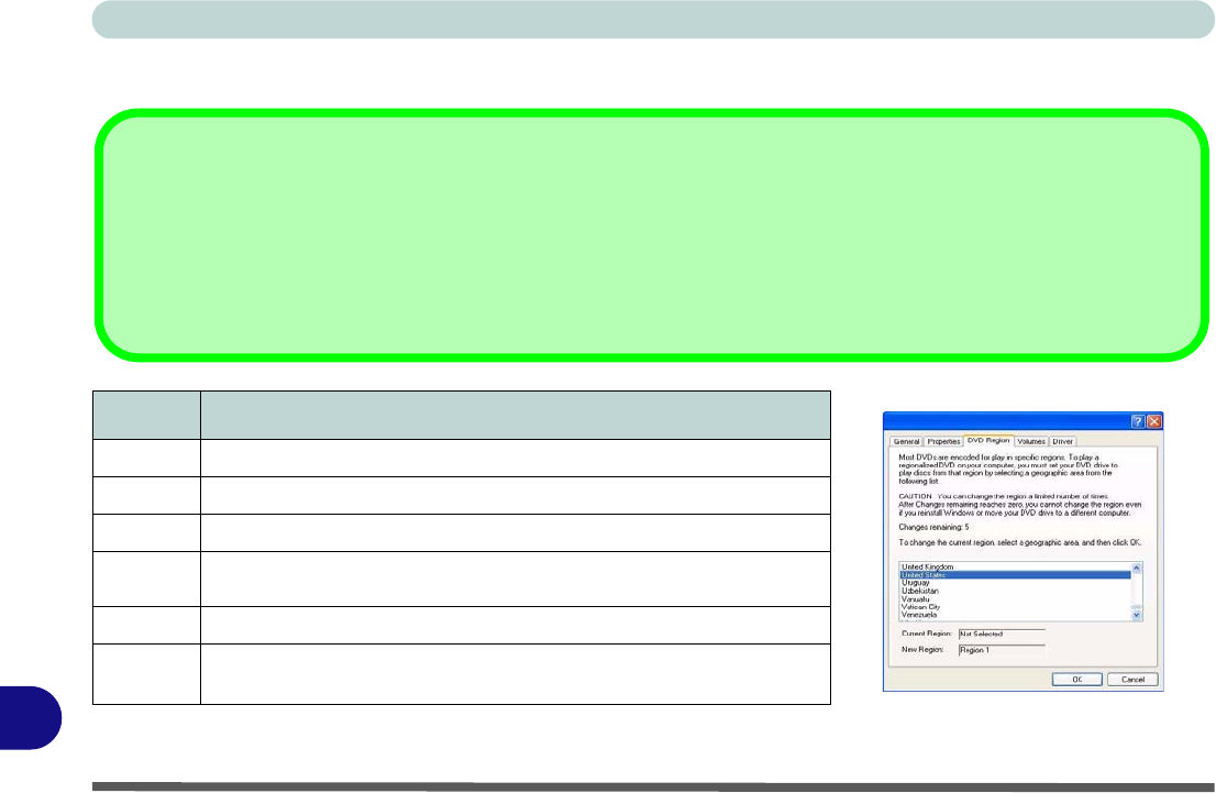
DVD Regional Codes
Region Geographical Location
1 USA, Canada
2 Western Europe, Japan, South Africa, Middle East & Egypt
3 South-East Asia, Taiwan, South Korea, The Philippines, Indonesia, Hong Kong
4South & Central America, Mexico, Australia,
New Zealand
5 N Korea, Russia, Eastern Europe, India & Most of Africa
6 China
Table D - 1 - DVD Region Codes Figure D - 1 - DVD Regions
Changing DVD Regional Codes
Go to the Control Panel and double-click System > Hardware (tab), click Device Manager, then click the + next to DVD/CD-ROM drives.
Double-click on the DVD-ROM device to bring up the Properties dialogue box, and select the DVD Region (tab) to bring up the control
panel to allow you to adjust the regional code.
DVD region detection is device dependent, not OS-dependent. You can select your module’s region code 5 times. The fifth selection is
permanent. This cannot be altered even if you change your operating system or you use the module in another computer.
Windows XP Information
Windows XP Start Menu & Control Panel D - 3
D
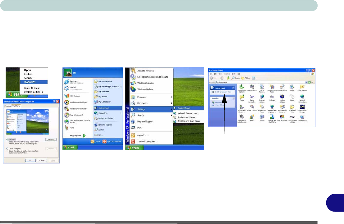
Windows XP Start Menu & Control Panel
Most of the control panels, utilities and programs within Windows XP (and most other Windows versions) are
accessed from the Start menu. When you install programs and utilities they will be installed on your hard disk
drive, and a shortcut will usually be placed in the Start menu and/or the desktop. You can customize the look of
the Start menu by right-clicking the Start menu and selecting Properties from the menu.
In many instances throughout this manual you will see an instruction to open the Control Panel. The Control
Panel is accessed from the Start menu, and it allows you to configure the settings for most of the key features
in Windows (e.g. power, video, network, audio etc.). Windows XP provides basic controls for many of the fea-
tures, however many new controls are added (or existing ones are enhanced) when you install the drivers. To see
all controls it may be necessary to toggle off Category View.
Figure D - 2 - Start Menu & Control Panel
Click here to toggle Category View
Windows XP Information
D - 4 TouchPad and Buttons/Mouse
D
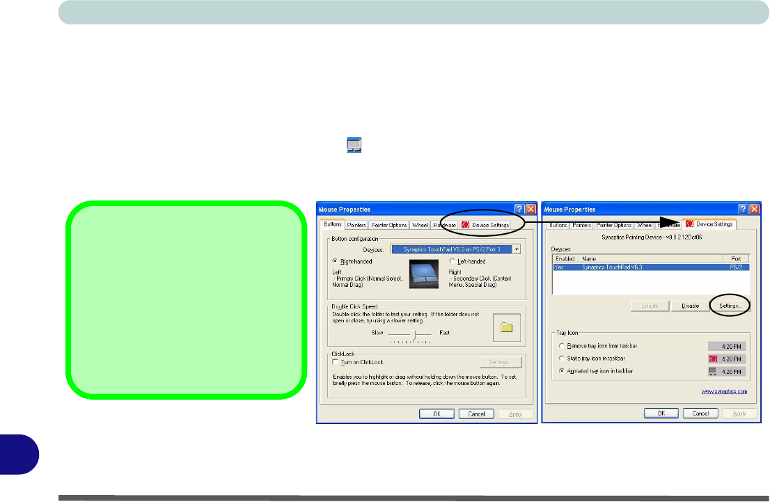
TouchPad and Buttons/Mouse
The TouchPad is an alternative to the mouse; however, you can also add a mouse to your computer through one
of the USB ports. The TouchPad buttons function in much the same way as a two-button mouse.
Once you have installed the TouchPad driver (see “TouchPad” on page D - 31) you can configure the functions
by double-clicking the TouchPad driver icon on the taskbar. You may then configure the TouchPad tapping,
buttons, scrolling, pointer motion and sensitivity options to your preferences. You will find further information
at www.synaptics.com.
Figure D - 3 - Mouse Properties
Mouse Driver
If you are using an external mouse
your operating system may be able to
auto-configure your mouse during its
installation or only enable its basic
functions. Be sure to check the de-
vice’s user documentation for details.
Windows XP Information
Function Keys D - 5
D
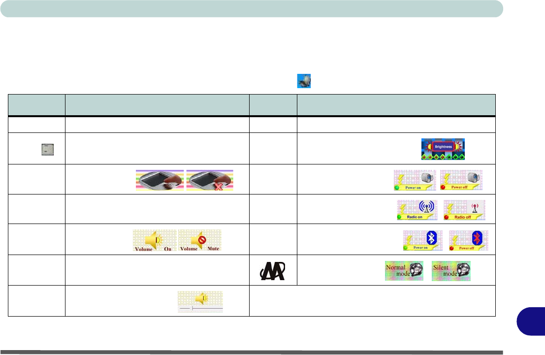
Function Keys
The function keys (F1 - F12 etc.) will act as hot keys when pressed while the Fn key is held down. In addition
to the basic function key combinations; visual indicators are available when the hot key utility is installed (see
“Hot Key” on page D - 31). When the driver is installed, an icon will appear in the taskbar.
Table D - 2 - Hot Key Functions & Indicators
Keys Function Keys Function
Fn + ~ Play/Pause (in Audio/Video Programs) Fn + F7 Display Toggle
Fn + _ 3.5G Module Power Toggle Fn + F8/F9 Brightness Decrease/Increase
Fn + F1 TouchPad Toggle Fn + F10 PC Camera Power Toggle
Fn + F2 Turn LCD Backlight Off
(Press a key to or use TouchPad to turn on) Fn + F11 WLAN Module Power Toggle
Fn + F3 Mute Toggle Fn + F12 Bluetooth Module Power Toggle
Fn + F4 Sleep Toggle *Silent Mode Toggle
Fn + F5/F6 Volume Decrease/Increase *When enabled, Silent Mode will reduce fan noise and save power
consumption. Note this may reduce computer performance.
Windows XP Information
D - 6 Audio Features
D
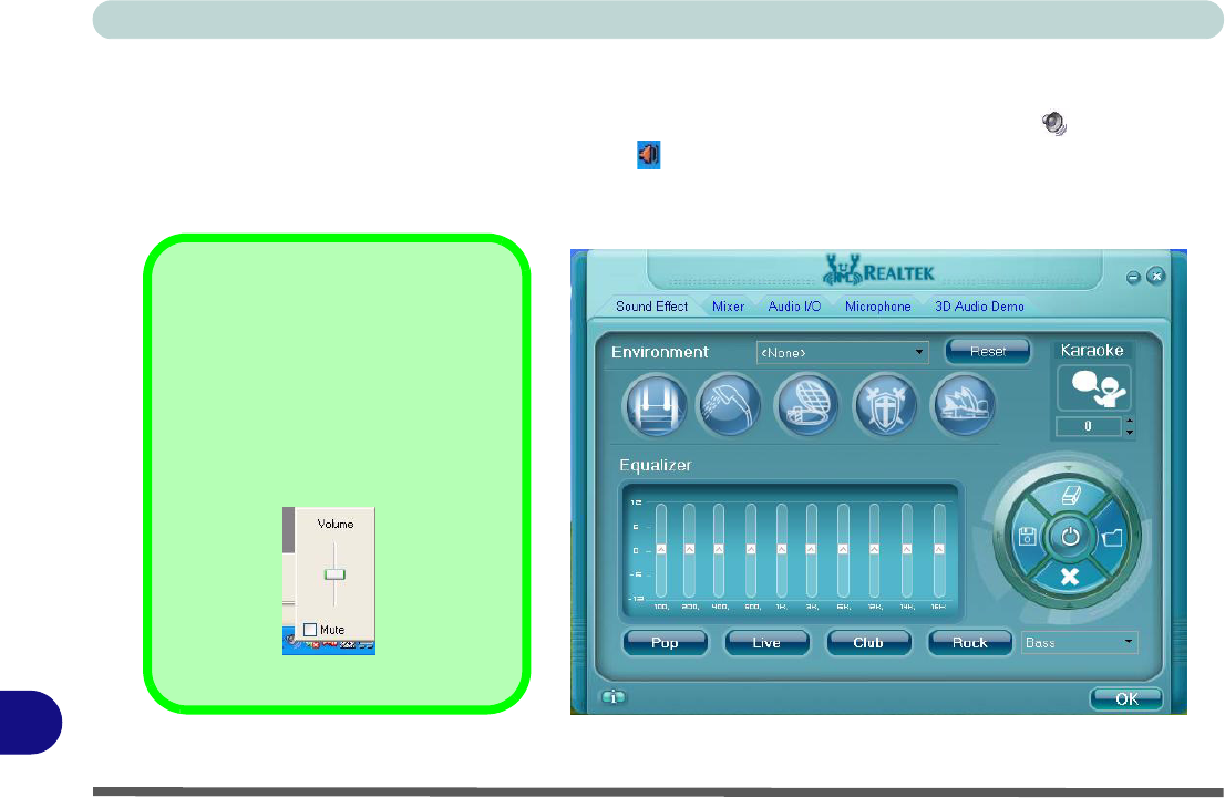
Audio Features
You can configure the audio options on your computer from the Sounds and Audio Devices Windows con-
trol panel, or from the Realtek HD Audio Manager icon in the taskbar/control panel (this will bring up the
Realtek Audio Configuration menus). The volume may also be adjusted by means of the Fn + F5/F6 key com-
bination.
Figure D - 4 - Realtek Audio Configuration Menus
Sound Volume Adjustment
How high the sound volume can be
set depends on the setting of the vol-
ume control within Windows (and the
volume control function keys on the
computer). Click the Volume icon on
the taskbar to check the setting.

Windows XP Information
Video Features D - 7
D
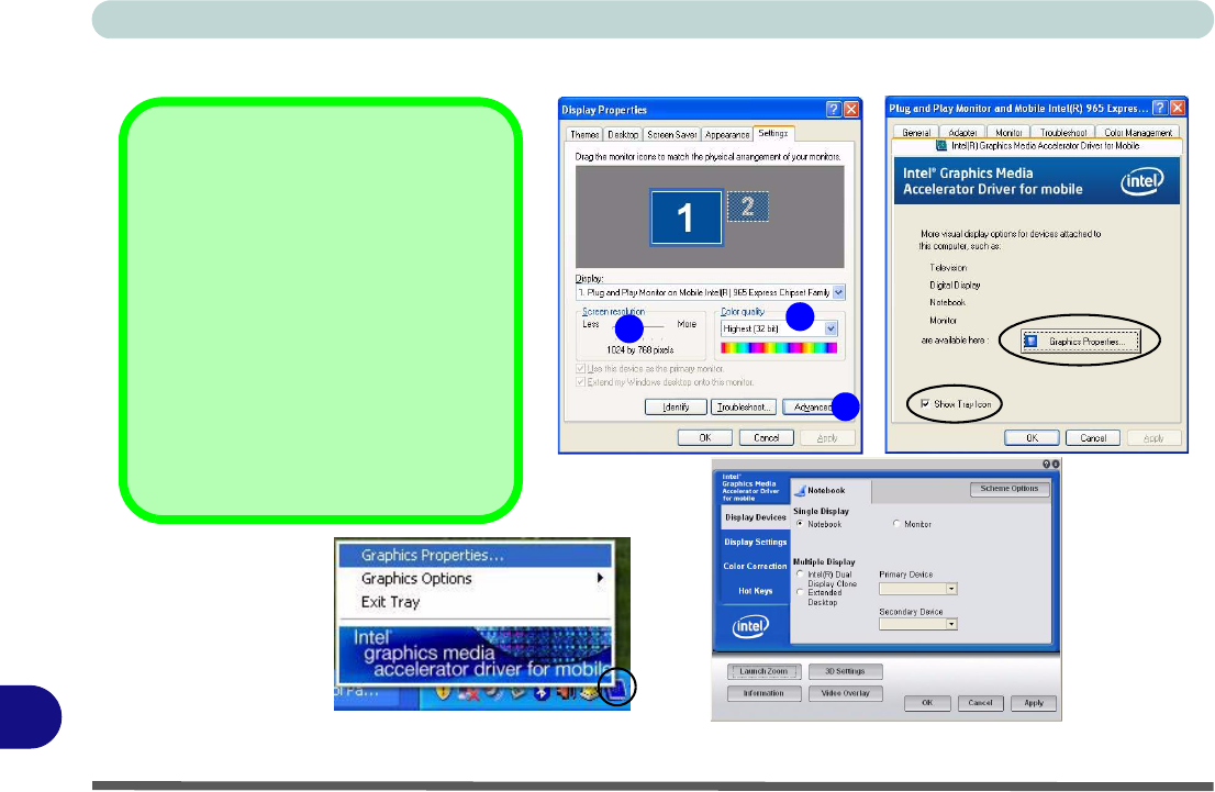
Video Features
Your computer has built-in Intel (Intel GM965) video. You can switch display devices, and configure display
options, from the Display Properties control panel in Windows as long as the appropriate video driver is in-
stalled.
To access Display Properties in Windows:
1. Click Start, point to Settings and click Control Panel (or just click Control Panel).
2. Double-click Display (icon) - In the Appearances and Themes category.
3. Click Settings (tab) in the Display Properties dialog box.
4. Move the slider to the preferred setting in Screen resolution (Figure D - 5 on page D - 8).
5. Click the arrow, and scroll to the preferred setting in Color quality (Figure D - 5 on page D - 8).
6. You can also access Display Properties by right-clicking the desktop and scrolling down and clicking
Properties. Click Settings (tab) and adjust as above.
7. Open the Display Properties control panel, and click Advanced (button) (Figure D - 5 on page D - 8) to
bring up the Advanced properties tabs.
8. Click the Intel(R) Graphics Media Accelerator Driver for Mobile tab, and click Graphics Properties (button)
to make any video adjustments you require.
9. You can also access Graphics Properties from the Windows Intel(R) GMA Driver for Mobile control panel, or
from the taskbar icon .
Dynamic Video Memory Technology
Intel® DVMT automatically and dynamically allocates as much (up to 256MB) system memory (RAM) as need-
ed to the video system (the video driver must be installed). DVMT returns whatever memory is no longer need-
ed to the operating system.
12
3
Windows XP Information
D - 8 Video Features
D
Display & Graphics Properties
Figure D - 5 - Display & Graphics Properties
12
3
Taskbar Icon
You can also access the controller prop-
erties from the taskbar. Click on the icon
to bring up the menu and scroll to
Graphics Properties.
If you cannot see the tray icon go to the
Intel(R) Graphics Media Accelerator
Driver for Mobile tab and click the
“Show Tray Icon” tickbox. Alternatively
right-click the desktop and select Graph-
ics Options > Tray Icon > Enable.
Windows XP Information
Video Features D - 9
D
You may make changes to the devices, color, schemes, Hot Keys etc. by clicking the appropriate menu item or
button. Click Information (button) to obtain useful information about the graphics properties of the computer,
and see the Support tab in Information to get weblinks to the latest information on the Intel Website.
Figure D - 6 - Intel GMA Driver for Mobile
Function Key Combination
You can use the Fn + F7 key
combination to toggle through
the display options:
• Notebook Only
• External Display Only
• Notebook + External Display
Make sure you give the displays
enough time to refresh.
Intel Display Note
Note that the notebook is the de-
fault Primary display device and
may not be changed.

Windows XP Information
D - 10 Video Features
D
Display Devices & Options
Besides the built-in LCD, you can also use an external VGA monitor (CRT) or external Flat Panel Display
as your display device. A VGA monitor/Flat Panel Display connects to the external monitor port. The following
display modes are available.
Figure D - 7 - Display Options
Intel Display Mode Description
Single Display One of the connected displays is used as the display device
Multiple Display - Intel(R)
Dual Display Clone Both connected displays output the same view and may be configured independently
Multiple Display - Extended
Desktop Both connected displays are treated as separate devices, and act as a virtual desktop
Switching Modes When Using the Power DVD Application
Switch display modes before playing any DVD in the Power DVD Application it is not be possible to switch display
modes while a DVD is playing (you will be required to stop the DVD playing, switch display modes, then start the DVD
playing again).
Windows XP Information
Attaching Other Displays D - 11
D
Attaching Other Displays
If you prefer to use a monitor or flat panel display, connect it to the external monitor port at the rear of the com-
puter.
1. Attach your external display to the external monitor port, and turn it on.
2. Go to the Intel GMA Graphics Properties control panel and click Display Devices.
3. Click to choose the display option from the Multiple/Single Display menu.
4. Click Apply, and OK to confirm the settings change.
Figure D - 8 - Display Devices
Windows XP Information
D - 12 Attaching Other Displays
D
To Enable Intel(R) Dual Display Clone (Intel GMA)
1. Attach your external display to the external monitor port, and turn it on.
2. Go to the Intel GMA Graphics Properties control panel and click Display Devices.
3. Click to choose Intel(R) Dual Display Clone (Multiple Display).
4. Click Apply, and OK to confirm the settings change.
5. Click Display Settings to adjust the settings for the attached devices.
Figure D - 9 - Display Devices - Intel(R) Dual Display Clone
Windows XP Information
Attaching Other Displays D - 13
D
To Enable Extended Desktop (Intel GMA)
1. Attach your external display to the external monitor port, and turn it on.
2. Go to the Intel GMA Graphics Properties control panel and click Display Devices.
3. Click to choose Extended Desktop (Multiple Display).
4. Click Apply, and OK to confirm the settings change.
5. Click Display Settings to adjust the settings for the attached devices.
Figure D - 10 - Display Devices - Extended Desktop
Click the appropriate
monitor icon and drag
it to match the physical
arrangement you wish
to use (e.g. the second-
ary display may be ex-
tended left/right/above/
below the primary dis-
play).
Click Display Settings
to make any adjust-
ments required.
Display Settings
Extended Desktop
You can have different
Colors, Screen Area and
Monitor Refresh Rates for
each display device pro-
vided your monitor can
support them.
You can drag the monitor
icons to match the physi-
cal layout of your displays.
Icons and programs may
also be dragged between
the displays.
Windows XP Information
D - 14 Attaching Other Displays
D
To Enable Extended Desktop (Windows Display Properties)
1. Attach your external monitor to the external monitor port, and turn it on.
2. Click Start, point to Settings (or click Control Panel) and click Control Panel (if you are in Category View
choose Appearance and Themes).
3. Double-click Display (icon).
4. In the Display Properties dialog box, click Settings (tab).
5. Click the monitor icon (e.g. ), and make sure you have checked “Extend my Windows desktop onto this
monitor.” and click Apply.
Figure D - 11 - Display Properties (Extended Desktop)
2
Click the appropriate mon-
itor icon (e.g. ) to be able
to select the option to ex-
tend the desktop on to it.
In this example the Primary
monitor is on the left, the
secondary display is on
the right.
2
1
2
Display Settings Extended
Desktop
Use the control panel to drag the mon-
itors to match the physical arrange-
ment you wish to use.
You can drag any icons or windows
across to either display desktop,
which makes it possible to have one
program visible in one of the displays,
and a different program visible in the
other display.

Windows XP Information
Power Management Features D - 15
D
Power Management Features
To conserve power, especially when using the battery, your computer uses the ACPI
power management system. Power management conserves power by controlling in-
dividual components of the computer (the monitor and hard disk drive) or the whole
system.
The Power Options control panel icon in Windows (see page D - 3) allows you to
configure power management features for your computer. You may conserve power
through individual components such as the monitor or hard disk, or you may use ei-
ther Stand by or Hibernate mode to conserve power throughout the system.
Advanced Configuration and Power Interface
The ACPI interface provides the computer with enhanced power saving techniques
and gives the operating system (OS) direct control over the power and thermal states
of devices and processors. For example, it enables the OS to set devices into low-
power states based on user settings and information from applications. ACPI is fully
supported in Windows XP.
OS Note
Power management
functions will vary
slightly depending on
your operating system.
For more information it
is best to refer to the
user’s manual of your
operating system.
(Note: All pictures
used on the following
pages are from the
Windows XP OS.)

Windows XP Information
D - 16 The Power Sources
D
The Power Sources
The computer can be powered by either an AC/DC adapter or a battery pack.
AC/DC Adapter
Use only the AC/DC adapter that comes with your computer. The wrong type of AC/DC adapter will damage
the computer and its components.
1. Attach the AC/DC adapter to the DC-in jack at the rear of the computer.
2. Plug the AC power cord into an outlet, and then connect the AC power cord to the AC/DC adapter.
3. Raise the lid/LCD to a comfortable viewing angle.
4. Press the power button to turn “On”.
Battery
The battery allows you to use your computer while you are on the road or when an electrical outlet is unavailable.
Battery life varies depending on the applications and the configuration you're using. To increase battery life,
let the battery discharge completely before recharging (see “How do I completely discharge the battery?”
on page D - 26).
We recommend that you do not remove the battery. For more information on the battery, please refer to “Battery
Information” on page D - 23.

Windows XP Information
Turning on the Computer D - 17
D
Turning on the Computer
Now you are ready to begin using your computer. To turn it on simply press the pow-
er button on the front panel.
When the computer is on, you can use the power button as a Stand by/Hibernate/
Shutdown hot-key button when it is pressed for less than 4 seconds (pressing and
holding the power button for longer than this will shut the computer down). Use
Power Options in the Windows control panel to configure this feature.
Shutdown
Note that you should al-
ways shut your comput-
er down by choosing the
Turn Off Computer
command from the Start
menu in Windows. This
will help prevent hard
disk or system prob-
lems.
Forced Off
If the system “hangs”, and the Ctrl + Alt + Del key combination doesn’t work, press the pow-
er button for 4 seconds, or longer, to force the system to turn itself off.
Power Button as Stand by or Hibernate Button
If you are using a fully ACPI-compliant OS, (such as Windows XP) you can use the OS’s
“Power Options” control panel to set the power button to send the system into Stand by or
Hibernate mode (see your OS’s documentation, or “Configuring the Power Button” on
page D - 22 for details).
Windows XP Information
D - 18 Power Schemes
D
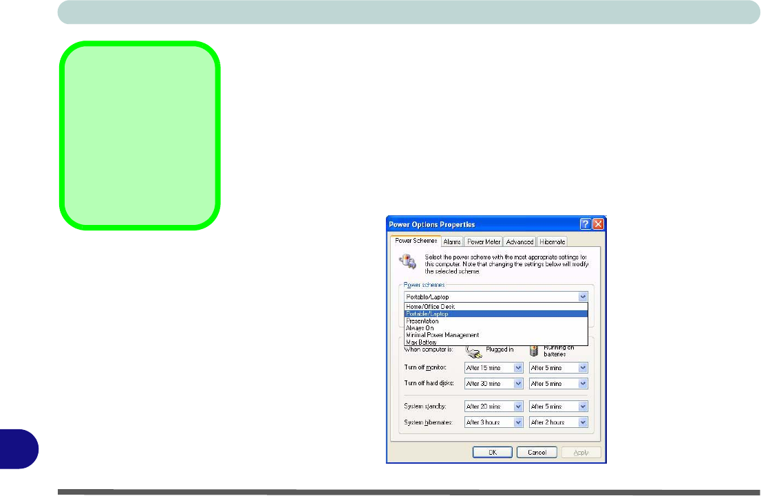
Power Schemes
You can set your computer to conserve power through individual components by
means of Power Schemes. You can also adjust the settings for each scheme to set
the monitor to turn off after a specified time, and the computer's hard disk motor to
turn off if the hard disk drive has not been accessed for a specified period of time (if
the system reads or writes data, the hard disk motor will be turned back on). The
schemes may also be set to set a specified time for the system to enter Stand by or
Hibernate modes (see “System Power Options” on page D - 20).
Resuming
Operation
Press a key on the key-
board, or move the
mouse/TouchPad to re-
sume from Monitor or
Hard Disk Stand by.
Figure D - 12
Power Schemes

Windows XP Information
Power Schemes D - 19
D
Each Windows Power Scheme will also adjust the processor performance of your machine in order to save pow-
er. This is worth bearing in mind if you are experiencing any reduced performance (especially under DC/battery
power).
Choose the Home/Office Desk scheme for maximum performance when the computer is powered from an AC
power source. Choose the Max Battery scheme (bear in mind that this scheme may slow down the overall per-
formance of the computer in order to save power) for maximum power saving when the computer is battery (DC
power) powered. Windows will use Portable/Laptop as the default scheme.

Windows XP Information
D - 20 System Power Options
D
System Power Options
You can use the system power options to stop the computer’s operation and restart
where you left off. This system features Stand by and Hibernate sleep mode levels
(Hibernate mode will need to be enabled by clicking the option in the Hibernate tab
in the Power Options control panel - see “Hibernate” on page D - 21).
Hibernate Mode vs. Shutdown
Hibernate mode and Shutdown are the same in that the system is off and you need to
press the power button to turn it on. Their main difference is:
When you come back from hibernation, you can return to where you last left off
(what was on your desktop) without reopening the application(s) and file(s) you last
used.
You can use either method depending on your needs.
Stand by Mode vs. Hibernate Mode
If you want to stay away from your work for just a while, you can put the system on
Stand by instead of in hibernation. It takes a longer time to wake up the system from
Hibernate mode than from Stand by mode.
Stand by/Hibernate
or Shutdown Error
The computer may stop
responding when you
put it into (or resume
from) Stand By or Hiber-
nate, or when you shut
down.
This error is caused by
power management
within Windows XP,
when applied to a PC
Camera attached to the
internal USB hub.
Microsoft has posted a
Hotfix for this error on its
website (search for Hot-
fix KB909667).
Download and install the
Hotfix to correct this er-
ror.
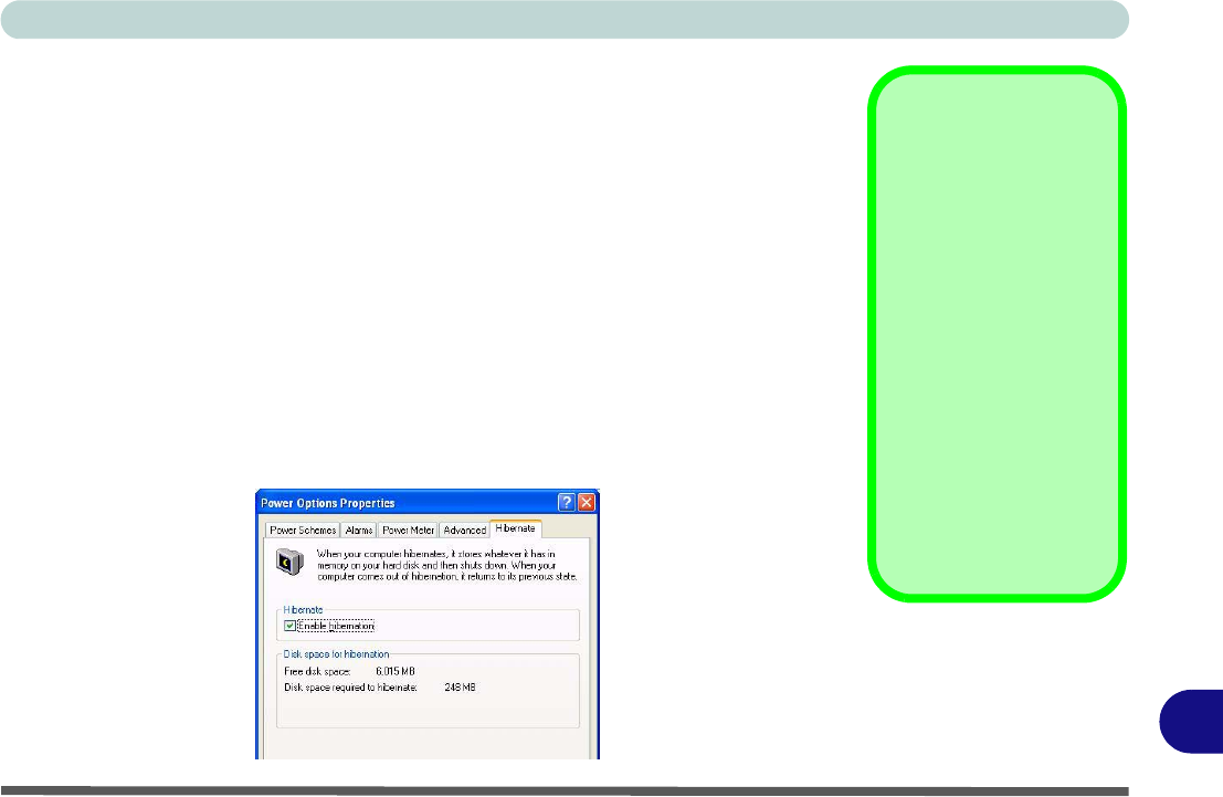
Windows XP Information
System Power Options D - 21
D
Stand by
Stand by saves the least amount of power, but takes the shortest time to return to full
operation. During Stand by the hard disk is turned off, and the CPU is made to idle
at its slowest speed. All open applications are retained in memory. When you are not
using your computer for a certain length of time, which you specify in the operating
system, it will enter Stand by mode to save power.
Hibernate
Hibernate uses no power and saves all of your information on a part of the HDD be-
fore it turns the system off. Although it saves the most power it takes the longest time
to return to full operation. You can set your computer to automatically enter Hiber-
nate mode when the battery power is almost depleted. You will need to enable Hi-
bernate mode from the Hibernate tab in the Power Options control panel. The
system will resume from Hibernate mode by pressing the power button.
System Resume
The system can resume
from Stand by mode by:
• Pressing the power
button
• Pressing the Sleep/
Resume key combi-
nation
• An incoming call
received on the
modem (if enabled)
• Network card (Wake
On LAN) activity (if
enabled)
Figure D - 13
Enable Hibernation
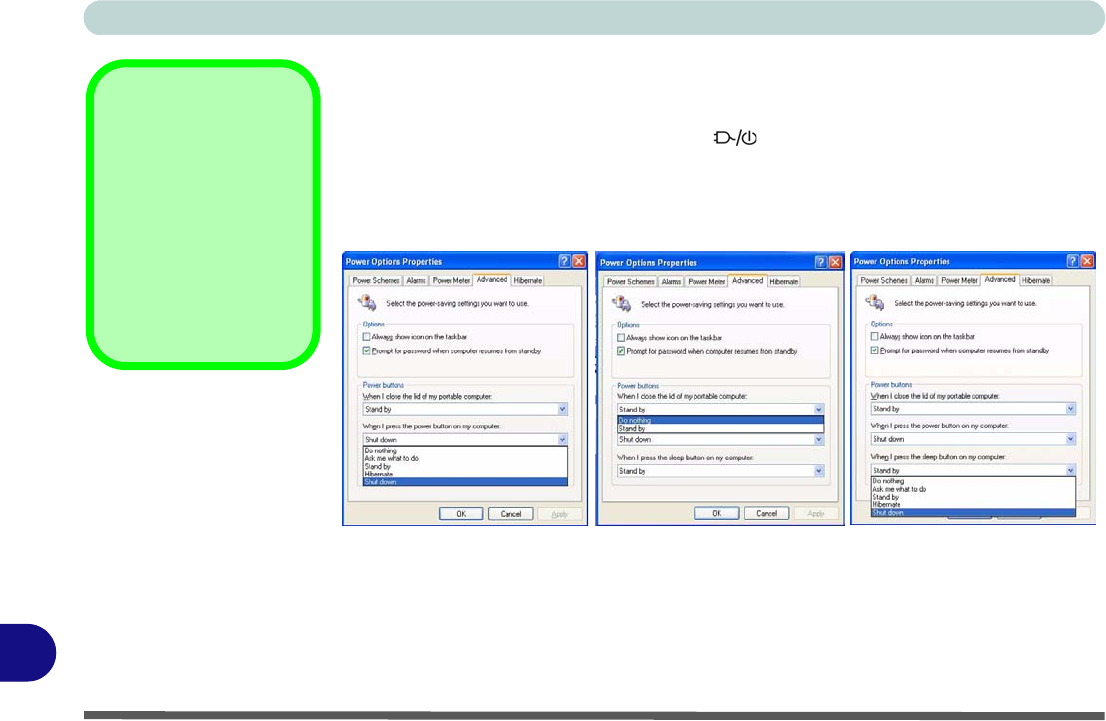
Windows XP Information
D - 22 Configuring the Power Button
D
Configuring the Power Button
The power button may be set to send the computer in to either Stand by or Hiber-
nate mode. In Stand by mode, the LED will blink green. In Hibernate mode
the LED will be off (battery) or orange (AC/DC adapter). If you are in a power saving
mode set to save power through individual components (e.g. hard disk, monitor), the
LED will remain green.
Sleep Button
You may also configure
the Sleep/Resume key
combination (Fn + F4)
from the menu illustrat-
ed. In Windows this is
referred to as the Sleep
button.
Figure D - 14
Power Options
(Advanced - Power
Buttons)
(Sleep) Button
Power Button Sleep/ResumeLid