User Manual


I
Preface
Notice
The company reserves the right to revise this publication or to change its contents without notice. Information
contained herein is for reference only and does not constitute a commitment on the part of the manufacturer or
any subsequent vendor. They assume no responsibility or liability for any errors or inaccuracies that may appear
in this publication nor are they in anyway responsible for any loss or damage resulting from the use (or misuse)
of this publication.
This publication and any accompanying software may not, in whole or in part, be reproduced, translated, trans-
mitted or reduced to any machine readable form without prior consent from the vendor, manufacturer or creators
of this publication, except for copies kept by the user for backup purposes.
Brand and product names mentioned in this publication may or may not be copyrights and/or registered trade-
marks of their respective companies. They are mentioned for identification purposes only and are not intended
as an endorsement of that product or its manufacturer.
©March 2008
Trademarks
This product incorporates copyright protection technology that is protected by method claims of certain U.S. pat-
ents and other intellectual property rights owned by Macrovision Corporation and other rights owners. Use of
this copyright protection technology must be authorized by Macrovision Corporation, and is intended for home
or other limited viewing uses only unless otherwise authorized by Macrovision Corporation. Reverse engineer-
ing or disassembly is prohibited.
Intel and Intel Core are trademarks/registered trademarks of Intel Corporation.

II
Preface
FCC Statement
(Federal Communications Commission)
This equipment has been tested and found to comply with the limits for a Class B digital device, pursuant to Part
15 of the FCC Rules. These limits are designed to provide reasonable protection against harmful interference in
a residential installation. This equipment generates, uses and can radiate radio frequency energy and, if not in-
stalled and used in accordance with the instructions, may cause harmful interference to radio communications.
However, there is no guarantee that interference will not occur in a particular installation. If this equipment does
cause harmful interference to radio or television reception, which can be determined by turning the equipment
off and on, the user is encouraged to try to correct the interference by one or more of the following measures:
• Re orient or relocate the receiving antenna.
• Increase the separation between the equipment and receiver.
• Connect the equipment into an outlet on a circuit different from that to which the receiver is connected.
• Consult the service representative or an experienced radio/TV technician for help.
Operation is subject to the following two conditions:
1. This device may not cause interference.
And
2. This device must accept any interference, including interference that may cause undesired operation of the
device.

III
Preface
FCC RF Radiation Exposure Statement:
1. This Transmitter must not be co-located or operating in conjunction with any other antenna or transmitter.
2. This equipment complies with FCC RF radiation exposure limits set forth for an uncontrolled environment. This
equipment should be installed and operated with a minimum distance of 20 centimeters between the radiator
and you body.
Warning
Use only shielded cables to connect I/O devices to this equipment. You are cautioned that changes or modifications not ex-
pressly approved by the manufacturer for compliance with the above standards could void your authority to operate the
equipment.
If your purchase option includes both Wireless LAN and 3.5G modules, then the appropriate antennas will be installed. Note
that In order to comply with FCC RF exposure compliance requirements, the antenna must not be co-located or operate in
conjunction with any other antenna or transmitter.

IV
Preface
IMPORTANT SAFETY INSTRUCTIONS
Follow basic safety precautions, including those listed below, to reduce the risk of fire, electric shock, and injury
to persons when using any electrical equipment:
1. Do not use this product near water, for example near a bath tub, wash bowl, kitchen sink or laundry tub, in a wet
basement or near a swimming pool.
2. Avoid using this equipment with a telephone line (other than a cordless type) during an electrical storm. There
may be a remote risk of electrical shock from lightning.
3. Do not use the telephone to report a gas leak in the vicinity of the leak.
4. Use only the power cord and batteries indicated in this manual. Do not dispose of batteries in a fire. They may
explode. Check with local codes for possible special disposal instructions.
5. This product is intended to be supplied by a Listed Power Unit (Full Range AC/DC Adapter – AC Input 100 -
240V, 50 - 60Hz, DC Output 19V, 3.42A OR 18.5V, 3.5A).
CAUTION
Always disconnect all telephone lines from the wall outlet before servicing or disassembling this equipment.
TO REDUCE THE RISK OF FIRE, USE ONLY NO. 26 AWG OR LARGER,
TELECOMMUNICATION LINE CORD
This Computer’s Optical Device is a Laser Class 1 Product
V
Preface
Instructions for Care and Operation
The notebook computer is quite rugged, but it can be damaged. To prevent this, follow these suggestions:
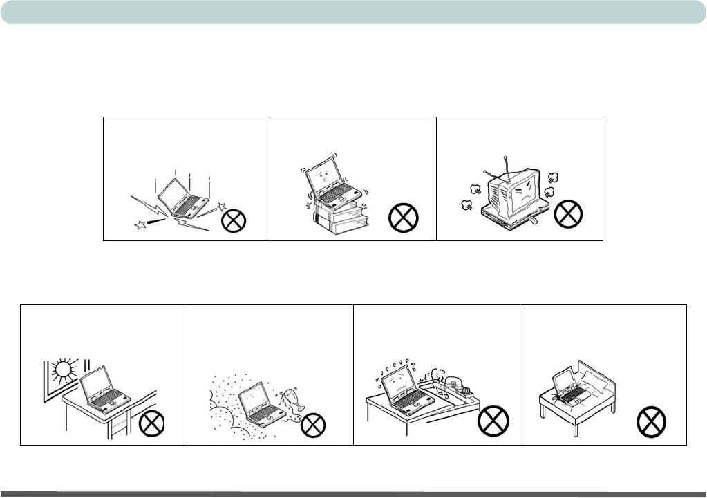
1. Don’t drop it, or expose it to shock. If the computer falls, the case and the components could be damaged.
2. Keep it dry, and don’t overheat it. Keep the computer and power supply away from any kind of heating ele-
ment. This is an electrical appliance. If water or any other liquid gets into it, the computer could be badly dam-
aged.
Do not expose the computer
to any shock or vibration.
Do not place it on an unstable
surface.
Do not place anything heavy
on the computer.
Do not expose it to excessive
heat or direct sunlight.
Do not leave it in a place
where foreign matter or mois-
ture may affect the system.
Don’t use or store the com-
puter in a humid environment.
Do not place the computer on
any surface that will block the
Vents/Fan Intakes.
VI
Preface
3. Avoid interference. Keep the computer away from high capacity transformers, electric motors, and other
strong magnetic fields. These can hinder proper performance and damage your data.
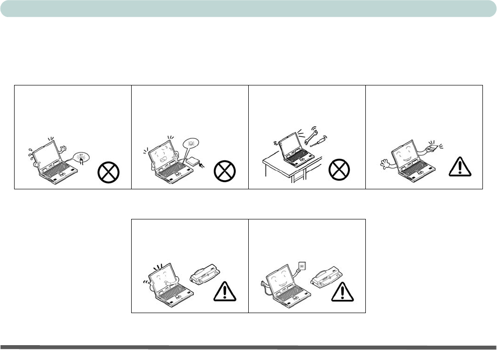
4. Follow the proper working procedures for the computer. Shut the computer down properly and don’t forget
to save your work. Remember to periodically save your data as data may be lost if the battery is depleted.
5. Take care when using peripheral devices.
Do not turn off the power
until you properly shut down
all programs.
Do not turn off any peripheral
devices when the computer is
on.
Do not disassemble the com-
puter by yourself.
Perform routine maintenance
on your computer.
Use only approved brands of
peripherals.
Unplug the power cord before
attaching peripheral devices.
VII
Preface
Power Safety
The computer has specific power requirements:
• Only use a power adapter approved for use with this computer.
• Your AC/DC adapter may be designed for international travel but it still requires a
steady, uninterrupted power supply. If you are unsure of your local power specifications,
consult your service representative or local power company.
• The power adapter may have either a 2-prong or a 3-prong grounded plug. The third
prong is an important safety feature; do not defeat its purpose. If you do not have access
to a compatible outlet, have a qualified electrician install one.
• When you want to unplug the power cord, be sure to disconnect it by the plug head, not
by its wire.
• Make sure the socket and any extension cord(s) you use can support the total current
load of all the connected devices.
• Before cleaning the computer, make sure it is disconnected from any external power
supplies (i.e. AC/DC adapter or car adapter).
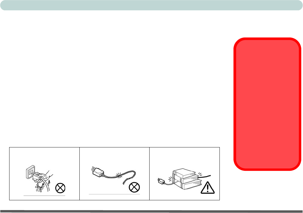
Do not plug in the power
cord if you are wet.
Do not use the power cord if
it is broken.
Do not place heavy objects
on the power cord.
Power Safety
Warning
Before you undertake
any upgrade proce-
dures, make sure that
you have turned off the
power, and discon-
nected all peripherals
and cables (including
telephone lines). It is
advisable to also re-
move your battery in
order to prevent acci-
dentally turning the
machine on.

VIII
Preface
Battery Precautions
• Only use batteries designed for this computer. The wrong battery type may explode, leak or damage the computer.
• Do not remove any batteries from the computer while it is powered on.
• Do not continue to use a battery that has been dropped, or that appears damaged (e.g. bent or twisted) in any way. Even
if the computer continues to work with a damaged battery in place, it may cause circuit damage, which may possibly
result in fire.
• Recharge the batteries using the notebook’s system. Incorrect recharging may make the battery explode.
• Do not try to repair a battery pack. Refer any battery pack repair or replacement to your service representative or qual-
ified service personnel.
• Keep children away from, and promptly dispose of a damaged battery. Always dispose of batteries carefully. Batteries
may explode or leak if exposed to fire, or improperly handled or discarded.
• Keep the battery away from metal appliances.
• Affix tape to the battery contacts before disposing of the battery.
• Do not touch the battery contacts with your hands or metal objects.
Battery Disposal & Caution
The product that you have purchased contains a rechargeable battery. The battery is recyclable. At the end of its useful life,
under various state and local laws, it may be illegal to dispose of this battery into the municipal waste stream. Check with
your local solid waste officials for details in your area for recycling options or proper disposal.
Danger of explosion if battery is incorrectly replaced. Replace only with the same or equivalent type recommended by the
manufacturer. Discard used battery according to the manufacturer’s instructions.

IX
Preface
Cleaning
Do not apply cleaner directly to the computer; use a soft clean cloth.
Do not use volatile (petroleum distillates) or abrasive cleaners on any part of the computer.
Servicing
Do not attempt to service the computer yourself. Doing so may violate your warranty and expose you and the
computer to electric shock. Refer all servicing to authorized service personnel. Unplug the computer from the
power supply. Then refer servicing to qualified service personnel under any of the following conditions:
• When the power cord or AC/DC adapter is damaged or frayed.
• If the computer has been exposed to rain or other liquids.
• If the computer does not work normally when you follow the operating instructions.
• If the computer has been dropped or damaged (do not touch the poisonous liquid if the LCD panel breaks).
• If there is an unusual odor, heat or smoke coming from your computer.
Removal Warning
When removing any cover(s) and screw(s) for the purposes of device upgrade, remember to replace the cover(s) and
screw(s) before turning the computer on.

X
Preface
Travel Considerations
Packing
As you get ready for your trip, run through this list to make sure the system is ready to go:
1. Check that the battery pack and any spares are fully charged.
2. Power off the computer and peripherals.
3. Close the display panel and make sure it’s latched.
4. Disconnect the AC/DC adapter and cables. Stow them in the carrying bag.
5. The AC/DC adapter uses voltages from 100 to 240 volts so you won’t need a second voltage adapter. However,
check with your travel agent to see if you need any socket adapters.
6. Put the notebook in its carrying bag and secure it with the bag’s straps.
7. If you’re taking any peripherals (e.g. a printer, mouse or digital camera), pack them and those devices’ adapters
and/or cables.
8. Anticipate customs - Some jurisdictions may have import restrictions or require proof of ownership for both
hardware and software. Make sure your documents are prepared.
Power Off Before Traveling
Make sure that your notebook is completely powered off before putting it into a travel bag (or any such container). Putting a
notebook which is powered on in a travel bag may cause the vent(s)/fan intake(s)/outlet(s) to be blocked. To prevent your
computer from overheating make sure nothing blocks the vent(s)/fan intake(s)/outlet(s) while the computer is in use.

XI
Preface
On the Road
In addition to the general safety and maintenance suggestions in this preface, and Chapter 8: Troubleshooting,
keep these points in mind:
Hand-carry the notebook - For security, don’t let it out of your sight. In some areas, computer theft is very
common. Don’t check it with normal luggage. Baggage handlers may not be sufficiently careful. Avoid knock-
ing the computer against hard objects.
Beware of Electromagnetic fields - Devices such as metal detectors & X-ray machines can damage the com-
puter, hard disk, floppy disks, and other media. They may also destroy any stored data - Pass your computer and
disks around the devices. Ask security officials to hand-inspect them (you may be asked to turn it on). Note:
Some airports also scan luggage with these devices.
Fly safely - Most airlines have regulations about the use of computers and other electronic devices in flight.
These restrictions are for your safety, follow them. If you stow the notebook in an overhead compartment, make
sure it’s secure. Contents may shift and/or fall out when the compartment is opened.
Get power where you can - If an electrical outlet is available, use the AC/DC adapter and keep your battery(ies)
charged.
Keep it dry - If you move quickly from a cold to a warm location, water vapor can condense inside the computer.
Wait a few minutes before turning it on so that any moisture can evaporate.
XII
Preface
Developing Good Work Habits
Developing good work habits is important if you need to work in front of the computer for long periods of time.
Improper work habits can result in discomfort or serious injury from repetitive strain to your hands, wrists or
other joints. The following are some tips to reduce the strain:
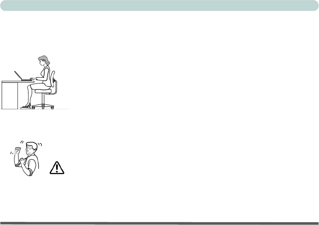
•Adjust the height of the chair and/or desk so that the keyboard is at or slightly below the
level of your elbow. Keep your forearms, wrists, and hands in a relaxed position.
•Your knees should be slightly higher than your hips. Place your feet flat on the floor or on a
footrest if necessary.
•Use a chair with a back and adjust it to support your lower back comfortably.
•Sit straight so that your knees, hips and elbows form approximately 90-degree angles when
you are working.
• Take periodic breaks if you are using the computer for long periods of time.
Remember to:
•Alter your posture frequently.
•Stretch and exercise your body several times a day.
•Take periodic breaks when you work at the computer for long periods of time. Frequent and
short breaks are better than fewer and longer breaks.

XIII
Preface
Lighting
Proper lighting and comfortable display viewing angle can reduce eye strain and muscle fatigue in your neck and
shoulders.
• Position the display to avoid glare or reflections from overhead lighting or outside sources of light.
• Keep the display screen clean and set the brightness and contrast to levels that allow you to see the screen clearly.
• Position the display directly in front of you at a comfortable viewing distance.
• Adjust the display-viewing angle to find the best position.
LCD Screen Care
To prevent image persistence on LCD monitors (caused by the continuous display of graphics on the screen for
an extended period of time) take the following precautions:
• Set the Windows Power Plans to turn the screen off after a few minutes of screen idle time.
• Use a rotating, moving or blank screen saver (this prevents an image from being displayed too long).
• Rotate desktop background images every few days.
• Turn the monitor off when the system is not in use.

XIV
Preface

Overview - 1
Quick Start Guide 1
Chapter 1: Quick Start Guide
Overview
This Quick Start Guide is a brief introduction to the basic features of your computer, to navigating around the
computer and to getting your system started.
Advanced Users
If you are an advanced user you may skip over most of this Quick Start Guide.You may also find the notes
marked with a of interest to you.
Beginners and Not-So-Advanced Users
If you are new to computers (or do not have an advanced knowledge of them) then
the information contained in this Quick Start Guide should be enough to get you up
and running. Eventually you should try to look through all the documentation (more
detailed descriptions of the functions, setup and system controls are covered in the
remainder of the User’s Manual), but do not worry if you do not understand every-
thing the first time. Keep this manual nearby and refer to it to learn as you go. You
may find it useful to refer to the notes marked with a as indicated in the margin.
Warning Boxes
No matter what your level please pay careful attention to the warning and safety information indicated by the
symbol. Also please note the safety and handling instructions as indicated in the Preface.
Notes
Check the light colored
boxes with the mark
above to find detailed
information about the
computer’s features.

2 - Overview
Quick Start Guide
1
Model Differences
This notebook series includes
two
different model types (there are also some designs styles that include aluminum
top covers - see below) which differ slightly in design style and LCD size (see
“Specifications” on page A - 1
).
Not Included
Operating Systems (e.g. Windows Vista) and applications (e.g. word processing, spreadsheet and database pro-
grams) have their own manuals, so please consult the appropriate manuals.
System Software
Your computer may already come with system software pre-installed. Where this is not the case, or where you
are re-configuring your computer for a different system, you will find this manual refers to the Microsoft Win-
dows Vista operating system.
Aluminum Covers
Note that this computer series includes some model designs with aluminum top covers. In order to clean this
type of cover use a soft, clean, slightly damp cloth to carefully wipe of any marks (e.g. fingerprints). DO NOT
use volatile (petroleum distillates) or abrasive cleaners on any part of the computer.

Overview - 3
Quick Start Guide 1
System Software
Your computer may already come with system software pre-installed. Where this is not the case, or where you
are re-configuring your computer for a different system, you will find the following operating systems are sup-
ported.
Table 1 - 1 - Operating Systems Supported
Operating System & Version Note
*Windows XP (Home or Professional) In order to run Windows XP without limitations or
decreased performance, your computer requires a
minimum 512MB of system memory (RAM)
Windows Vista - SP1 (64-bit) Home Basic Edition In order to run Windows Vista without limitations or
decreased performance, your computer requires a
minimum 1GB of system memory (RAM).
Windows Vista - SP1 (64-bit) Home Premium Edition
Windows Vista - SP1 (64-bit) Business/Enterprise/Ultimate Editions
Windows Vista Service Pack 1
Make sure you install Windows Vista Service Pack 1 (or a Windows Vista version which includes Service Pack 1) before
installing any drivers. Go to the Microsoft website for download details, or contact your service center.
4 - System Startup
Quick Start Guide
1
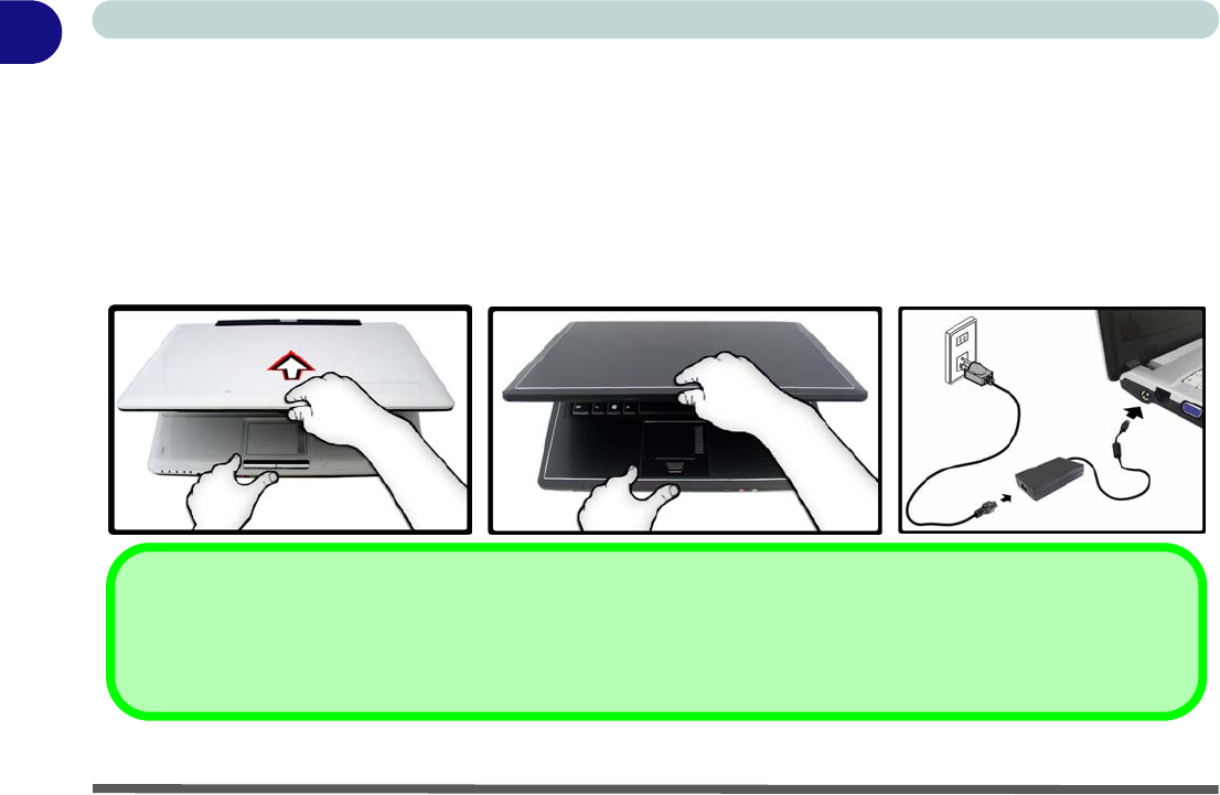
System Startup
1. Remove all packing materials, and place the computer on a stable surface.
2. Securely attach any peripherals you want to use with the notebook (e.g. keyboard and mouse) to their ports.
3. Attach the AC/DC adapter to the DC-In jack on the left of the computer, then plug the AC power cord into an
outlet, and connect the AC power cord to the AC/DC adapter.
4. Use one hand to carefully raise the lid/LCD to a comfortable viewing angle, while using the other hand (as illustrated
in
Figure 1 - 1
below) to support the base of the computer (
Note
:
Never
lift the computer by the lid/LCD).
5. Press the power button to turn the computer “on”.
Figure 1 - 1 - Opening the Lid/LCD/Computer with AC/DC Adapter Plugged-In
Shutdown
Note that you should always shut your computer down by choosing the Shut Down command from the Lock Button
Menu in Windows Vista. This will help prevent hard disk or system problems.
Model A Model B
System Map: LCD Panel Open - Model A - 5
Quick Start Guide 1
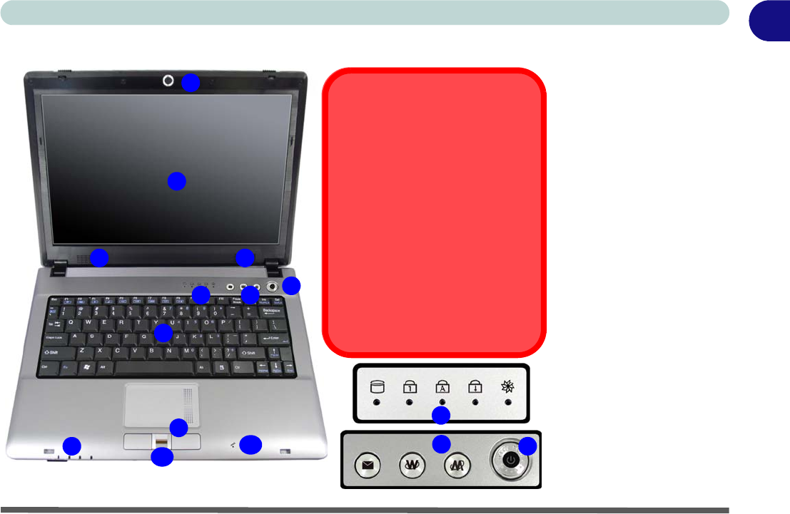
System Map: LCD Panel Open - Model A Figure 1 - 2
LCD Panel Open -
Model A
1. Built-In PC Camera
(
Optional
)
2. LCD
3. Speakers
4. Power Button
5. Hot Key Buttons
6. LED Status
Indicators
7. Keyboard
8. Touchpad &
Buttons
9. LED Power &
Communication
Indicators
10. Fingerprint Module
(Optional)
11. Built-In Microphone
Note the cleaning in-
structions for aluminum
covers - see page 2.
2
5
1
7
8
4
6
9
33
11
Wireless Device
Operation Aboard Aircraft
The use of any portable electronic
transmission devices aboard aircraft is
usually prohibited. Make sure the mod-
ule(s) are OFF if you are using the
computer aboard aircraft.
Use the key combinations to toggle
power to the 3.5G/WLAN/Bluetooth
modules, and check the LED indicator
icon to see if the modules are powered
on or not (see Table 1 - 5, on page 10/
Table 1 - 3, on page 7).
6
5
10 4
6 - System Map: LCD Panel Open - Model B
Quick Start Guide
1
System Map: LCD Panel Open - Model B
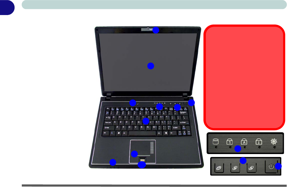
Figure 1 - 3
LCD Panel Open -
Model B
1. Built-In PC Camera
(
Optional
)
2. LCD
3. Built-In Microphone
4. Power Button
5. Hot Key Buttons
6. LED Status
Indicators
7. Keyboard
8. Touchpad &
Buttons
9. LED Power &
Communication
Indicators
10. Fingerprint Module
(Optional)
Note the cleaning in-
structions for aluminum
covers - see page 2.
2
5
1
7
8
4
6
9
3
Wireless Device
Operation Aboard Aircraft
The use of any portable electronic
transmission devices aboard aircraft is
usually prohibited. Make sure the mod-
ule(s) are OFF if you are using the
computer aboard aircraft.
Use the key combinations to toggle
power to the 3.5G/WLAN/Bluetooth
modules, and check the LED indicator
icon to see if the modules are powered
on or not (see Table 1 - 5, on page 10/
Table 1 - 3, on page 7).
6
5
10 4
Quick Start Guide
System Map: LCD Panel Open - Model B - 7
1
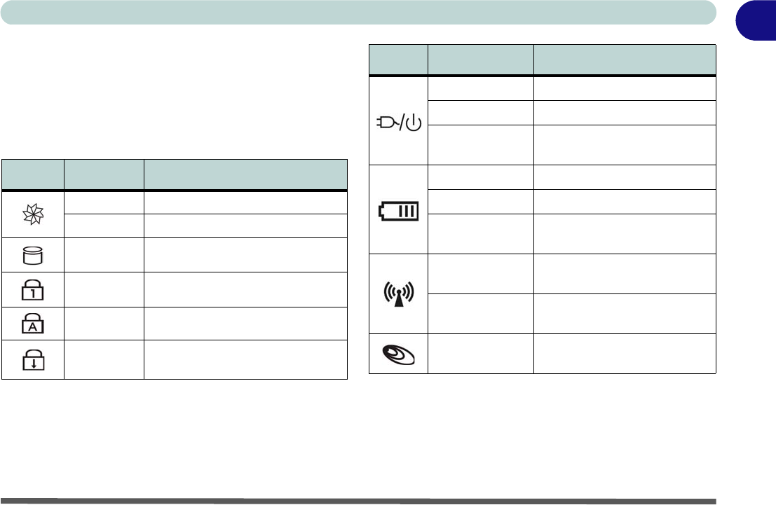
LED Indicators
The two sets of LED indicators (LED Status Indica-
tors and LED Power & Communication Indicators)
on the computer display helpful information about the
current status of the computer.
Table 1 - 2 - LED Status Indicators Table 1 - 3 - LED Power & Communication Indicators
Icon Color Description
Green Silent Mode Activated (see over)
Off Normal Mode Activated (see over)
Green Hard Disk Activity
Green Number Lock Activated
Green Caps Lock Activated
Green Scroll Lock Activated (to activate
press Fn & Scr Lk)
Icon Color Description
Orange DC Power is Plugged In
Green The Computer is On
Blinking Green The Computer is in Sleep
Mode
Orange The Battery is Charging
Green The Battery is Fully Charged
Blinking Orange The Battery Has Reached
Critically Low Power Status
Green The (optional) Wireless LAN
Module is Powered On
Orange The (optional) Bluetooth
Module is Powered On
Green The (optional) 3.5G Module is
Powered On
Quick Start Guide
8 - Hot Key Buttons & Keyboard
1
Hot Key Buttons & Keyboard
These buttons give instant access to the default Inter-
net browser and e-mail program, and allow you to tog-
gle the Silent Mode on/off with one quick button
press.
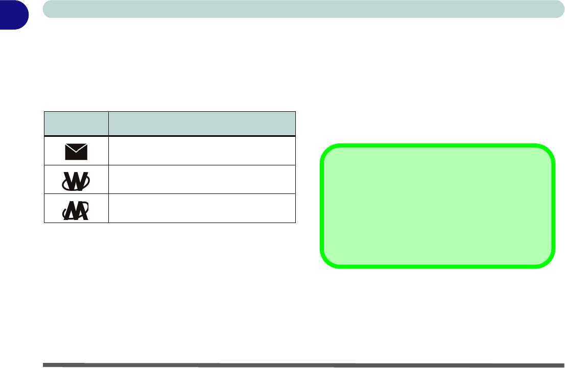
Table 1 - 4 - Hot Key Buttons
*When enabled, Silent Mode will reduce fan noise
and save power consumption. Note this may reduce
computer performance.
The keyboard has a numerical keypad for easy numer-
ic data input, and features Function Keys to allow you
to change operational features instantly.
Activate the Number Lock feature by pressing the
Num Lk key at the top right of the keyboard. You may
check if Number Lock is enabled or not by looking at
the LED status indicators.
Hot Key Function
Activate the Default E-Mail Browser
Activate the Default Internet Program
Toggle *Silent Mode (for power saving)
Other Keyboards
If your keyboard is damaged or you just want to make
a change, you can use any standard USB keyboard.
The system will detect and enable it automatically.
However special functions/AP-Key buttons unique to
the system’s regular keyboard may not work.
Keyboard - 9
Quick Start Guide 1
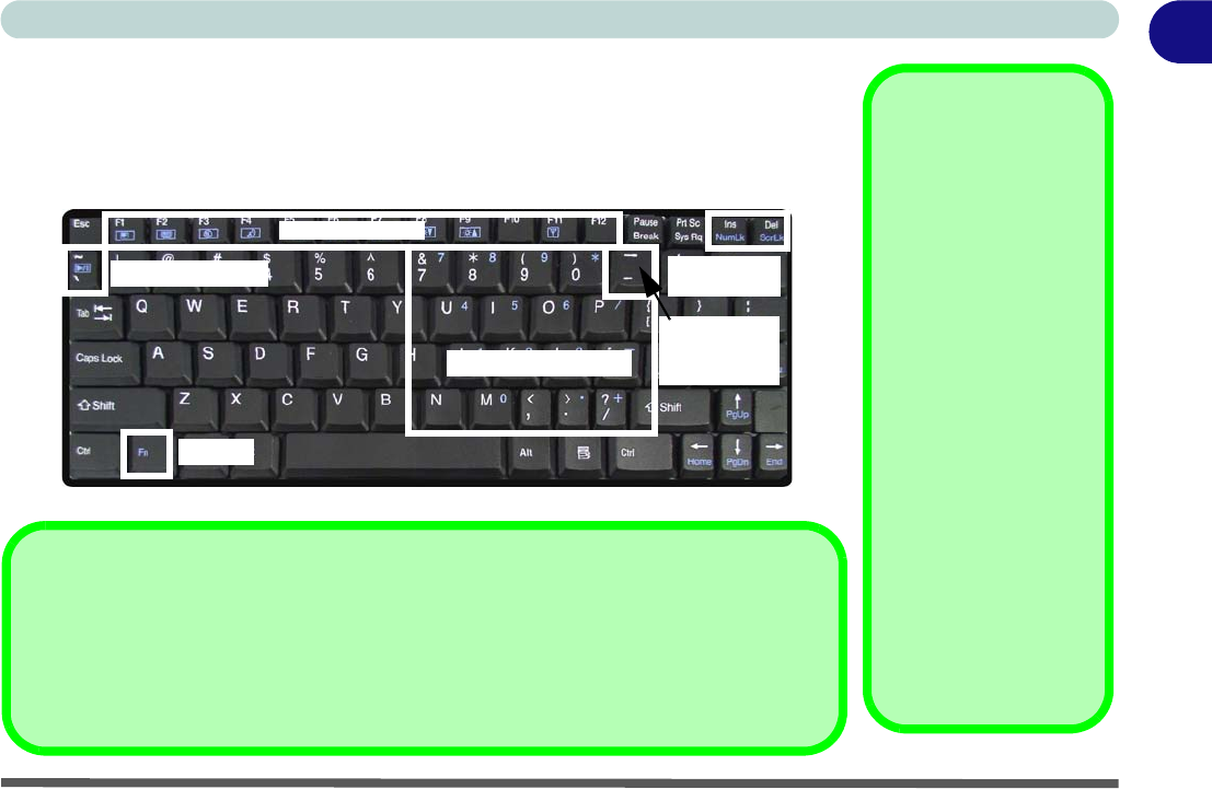
Keyboard
The keyboard has a numerical keypad for easy numeric data input, and features func-
tion keys to allow you to change operational features instantly. See Table 1 - 5, on
page 10 for full function key combination details.
Figure 1 - 4 - Keyboard
Other Keyboards
If your keyboard is
damaged or you just
want to make a
change, you can use
any standard USB key-
board. The system will
detect and enable it
automatically. Howev-
er special functions/
hot-keys unique to the
system’s regular key-
board may not work.
NumLk & ScrLk
Hold down the Fn Key
and either NumLk or
ScrLk to enable num-
ber or scroll lock, and
check the LED indica-
tor for status.
Numerical Keypad
Play/Pause Key
Function Keys
Toggle Key
3.5G Module
Power
NumLk &
ScrLk Keys
Fn Key
Special Characters
Some software applications allow the number-keys to be used with Alt to produce special
characters. These special characters can only be produced by using the numeric keypad.
Regular number keys (in the upper row of the keyboard) will not work. Make sure that Num-
Lk is on.
10 - Function/Hot Key Indicators
Quick Start Guide
1
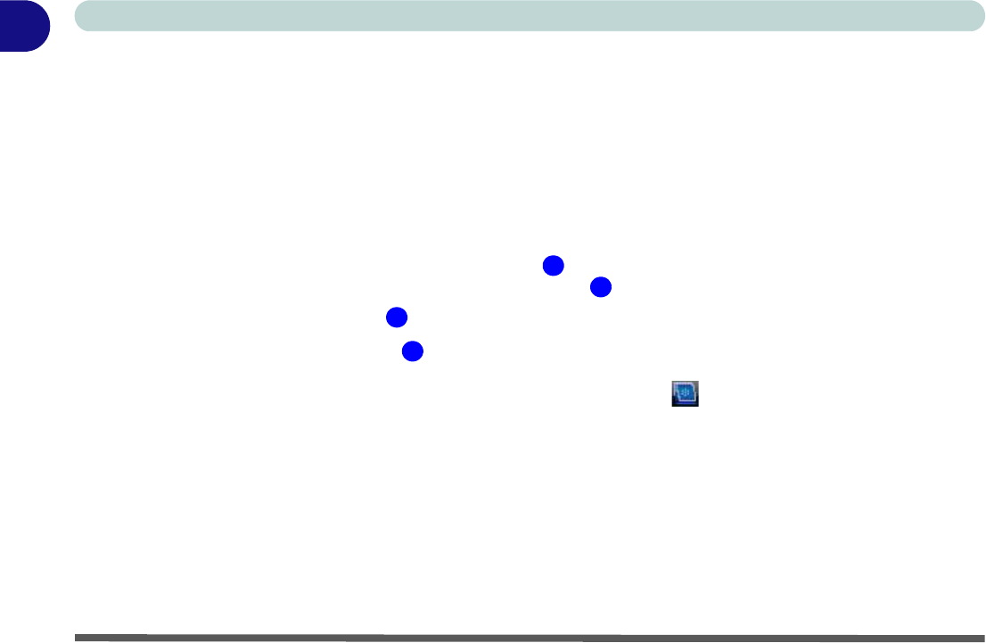
Function/Hot Key Indicators
The function keys (F1 - F12 etc.) will act as hot keys when pressed while the Fn key is held down. In addition
to the basic function key combinations; visual indicators are available when the hot key utility provided is in-
stalled. When the driver is installed, an icon will appear in the taskbar.
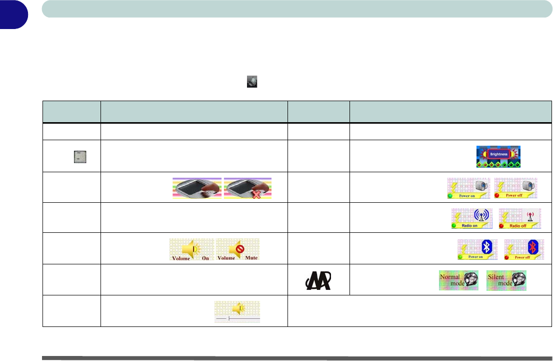
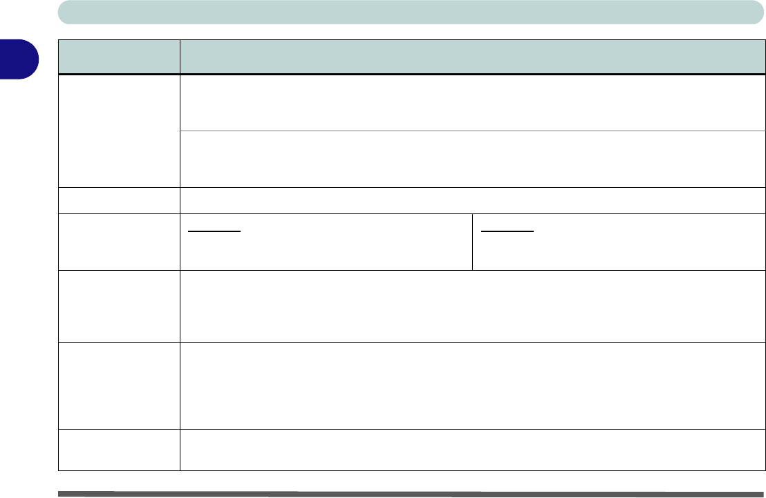
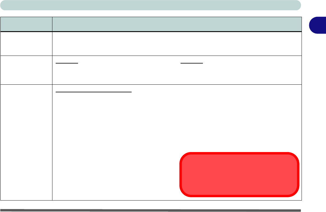
Table 1 - 5 - Function & Hot Key Indicators
Keys Function Keys Function
Fn + ~ Play/Pause (in Audio/Video Programs) Fn + F7 Display Toggle
Fn + 3.5G Module Power Toggle Fn + F8/F9 Brightness Decrease/Increase
Fn + F1 TouchPad Toggle Fn + F10 PC Camera Power Toggle
Fn + F2 Turn LCD Backlight Off
(Press a key to or use TouchPad to turn on) Fn + F11 WLAN Module Power Toggle
Fn + F3 Mute Toggle Fn + F12 Bluetooth Module Power Toggle
Fn + F4 Sleep Toggle *Silent Mode Toggle
Fn + F5/F6 Volume Decrease/Increase *When enabled, Silent Mode will reduce fan noise and save power consumption.
Note this may reduce computer performance.
System Map: Front & Rear Views - 11
Quick Start Guide 1
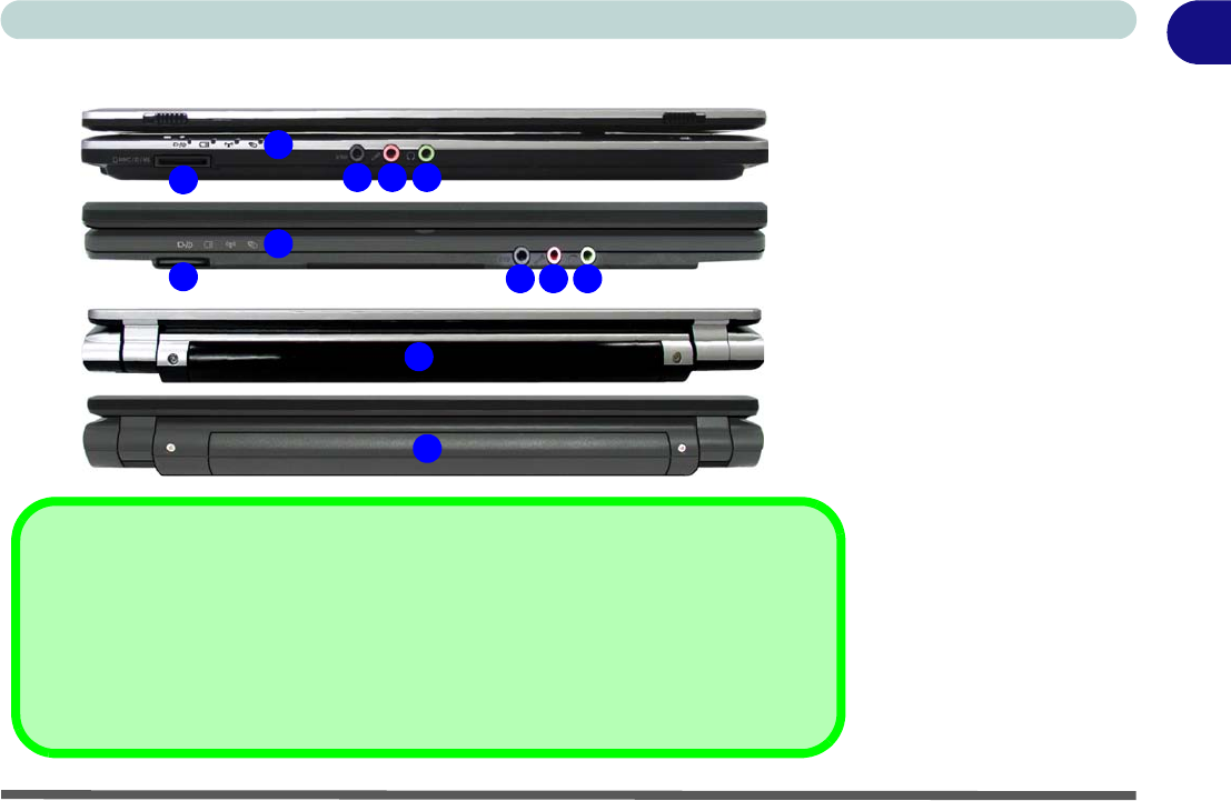
System Map: Front & Rear Views Figure 1 - 5
Front & Rear Views
1. LED Power & Com-
munication Indica-
tors
2. 7-in-1 Card Reader
3. S/PDIF-Out Jack
4. Microphone-In Jack
5. Headphone-Out
Jack
6. Battery
1
43 5
2
7-in-1 Card Reader
The card reader allows you to use the most popular digital storage card formats:
MMC (MultiMedia Card) / SD (Secure Digital) / MS (Memory Stick) /
MS Pro (Memory Stick Pro) / MS Duo (requires PC adapter) /
Mini SD (requires PC adapter) / RS MMC (requires PC adapter)
6
Model A
1
43 5
2
Model B
Model A
Model B
6
12 - System Map: Left & Right Views
Quick Start Guide
1
System Map: Left & Right Views
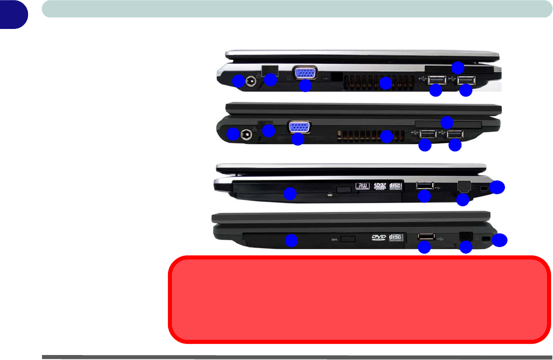
Figure 1 - 6
Left & Right Views
1. DC-In Jack
2. RJ-45 LAN Jack
3. External Monitor
Port
4. Vent/Fan Intake/
Outlet
5. 3 * USB 2.0 Ports
6. ExpressCard Slot
7. Optical Device
Drive Bay
8. RJ-11 Phone Jack
9. Security Lock Slot
14
2
78
35
5
Overheating
To prevent your computer from overheating make sure nothing blocks the vent(s)/fan in-
take(s) while the computer is in use.
5
9
6
Model A
Model B
4
12355
6
7589
Model A
Model B

System Map: Left & Right Views - 13
Quick Start Guide 1
Disk Eject Warning
Don’t try to eject a CD/DVD while the system is ac-
cessing it. This may cause the system to “crash”. Stop
the disk first then eject it, or press the stop button
twice.
CD/DVD Emergency Eject
If you need to manually eject a CD/DVD (e.g. due to
an unexpected power interruption) you may push the
end of a straightened paper clip into the emergency
eject hole. Do not use a sharpened pencil or any ob-
ject that may break and become lodged in the hole.
Don’t try to remove a floppy disk/CD/DVD while the
system is accessing it. This may cause the system to
“crash”.
Changing DVD Regional Codes
Go to the Control Panel and double-click Device
Manager (Hardware and Sound), then click the +
next to DVD/CD-ROM drives. Double-click on the
DVD-ROM device to bring up the Properties dialog
box, and select the DVD Region (tab) to bring up the
control panel to allow you to adjust the regional code.
DVD region detection is device dependent, not OS-
dependent. You can select your module’s region
code 5 times. The fifth selection is permanent. This
cannot be altered even if you change your operating
system or you use the module in another computer.
14 - System Map: Bottom View
Quick Start Guide
1
System Map: Bottom View
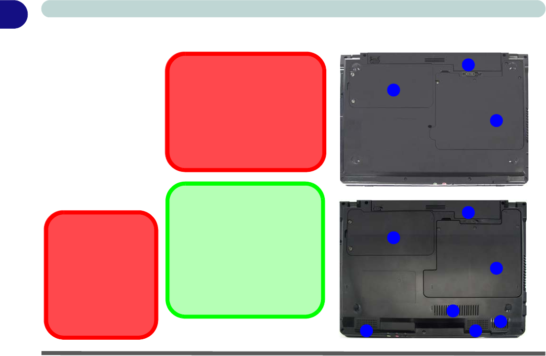
Figure 1 - 7
Bottom View
1. Battery
2. Hard Disk Bay
Cover
(3.5G Module
Location)
3. RAM & CPU Bay
Cover
4. Vent/Fan Intake/
Outlet
(Model B Only
5. Speakers
(Model B Only)
CPU
The CPU is not a user
serviceable part. Open-
ing this compartment, or
accessing the CPU in
any way, may violate
your warranty.
2
3
1
Battery Information
Always completely discharge, then
fully charge, a new battery before
using it. Completely discharge and
charge the battery at least once
every 30 days or after about 20
partial discharges.
Overheating
To prevent your computer from
overheating make sure nothing
blocks the Vent/Fan Intake while
the computer is in use. Model A
Model B
2
3
1
4
5 5 4
Windows Vista Start Menu & Control Panel - 15
Quick Start Guide 1
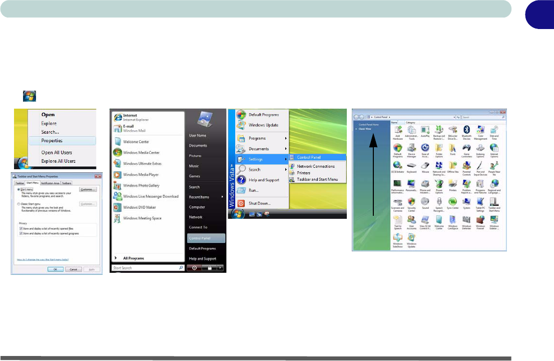
Windows Vista Start Menu & Control Panel
Most of the control panels, utilities and programs within Windows Vista (and most other Windows versions) are
accessed from the Start menu. When you install programs and utilities they will be installed on your hard disk
drive, and a shortcut will usually be placed in the Start menu and/or the desktop. Right-click the Start menu
icon , and then select Properties if you want to customize the appearance of the Start menu.
In many instances throughout this manual you will see an instruction to open the Control Panel. The Control
Panel is accessed from the Start menu, and it allows you to configure the settings for most of the key features
in Windows (e.g. power, video, network, audio etc.). Windows Vista provides basic controls for many of the fea-
tures, however many new controls are added (or existing ones are enhanced) when you install the drivers pro-
vided. To see all controls it may be necessary to toggle to Classic View on.
Figure 1 - 8 - Start Menu & Control Panel
Click here to toggle Classic View
16 - Video Features
Quick Start Guide
1
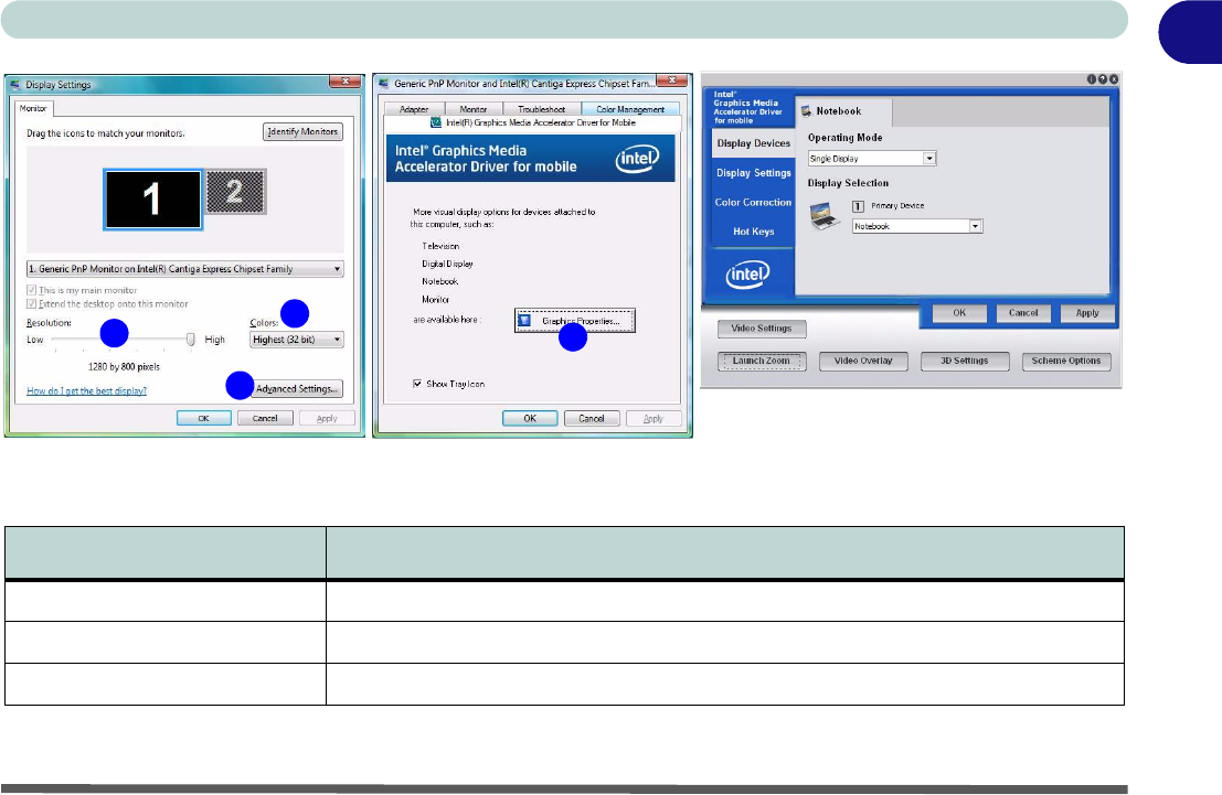
Video Features
You can switch display devices, and configure display options, from the Display Settings control panel (in Per-
sonalization) in Windows Vista as long as the appropriate Intel video driver is installed.
To access Display Settings in Windows Vista:
1. Click Start, and click Control Panel (or point to Settings and click Control Panel).
2. Click Adjust screen resolution under the Appearance and Personalization menu (or double-click
Personalization > Display Settings).
3. Move the slider to the preferred setting in Resolution: (Figure 1 - 9 on page 17).
4. Click the arrow, and scroll to the preferred setting In Colors: (Figure 1 - 9 on page 17).
5. Click Advanced Settings (button) (Figure 1 - 9 on page 17) and click Intel(R) GMA Driver for mobile
(tab).
6. Click Graphics Properties (button) (Figure 1 - 9 on page 17) to access the Intel GMA control panel (this
control panel can also be accessed by double-clicking Intel(R) GMA Driver for mobile in Classic View).
7. The Intel GMA control panel can also be accessed by clicking the icon in the taskbar and selecting
Graphics Properties from the menu.
Display Devices & Options
Besides the built-in LCD, you can also use an external VGA monitor (CRT) or external Flat Panel Display
connected to the external monitor port as your display device.
1
2
3
4
Video Features - 17
Quick Start Guide 1
Figure 1 - 9 - Display Properties Desktop
Table 1 - 6 - Display Options
Intel Display Mode Description
Single Mode One of the connected displays is used as the display device
Intel(R) Dual Display Clone Mode Both connected displays output the same view and may be configured independently
Extended Desktop Mode Both connected displays are treated as separate devices, and act as a virtual desktop
12
3
4
18 - Power Options
Quick Start Guide
1
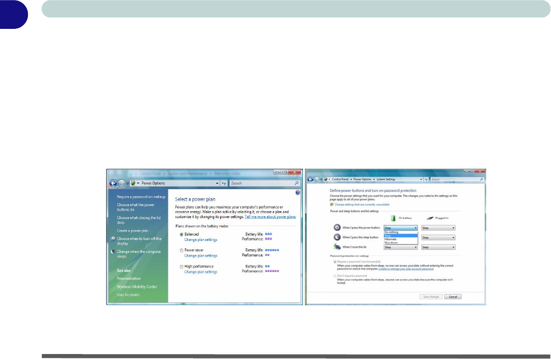
Power Options
The Power Options (Hardware and Sound menu) control panel icon in Windows (see page 15) allows you to
configure power management features for your computer. You can conserve power by means of power plans
and configure the options for the power button, sleep button, computer lid (when closed), display and sleep
mode from the left menu. Note that the Power saver plan may have an affect on computer performance.
Click to select one of the existing plans, or click Create a power plan in the left menu and select the options to
create a new plan. Click Change Plan Settings and click Change advanced power settings to access further con-
figuration options.
Figure 1 - 10 - Power Options
Note: Sleep is the default power saving state in Windows Vista

Specifications
Specifications A - 1
A
Appendix A: Specifications
Latest Specification Information
The specifications listed in this Appendix are correct at the time of going to press. Certain items (particularly processor types/
speeds and CD/DVD device types) may be changed, delayed or updated due to the manufacturer's release schedule. Check
with your service center for details.
Specifications
A - 2 Specifications
AFeature Specification
Processor Intel® Core™2 Duo Processor
35W - (478-pin) Micro-FC-PGA Package - Socket-P
45nm (45 Nanometer) Process Technology
6MB On-die L2 Cache & 1006MHz FSB
2.53/ 2.8 GHz
Intel® Core™2 Duo Processor
25W - (478-pin) Micro-FC-PGA Package - Socket-P
45nm (45 Nanometer) Process Technology
3MB On-die L2 Cache & 1006MHz FSB
2.13/ 2.4/ 2.53 GHz
Core Logic Intel GM45 + ICH9M Chipset
LCD Model A:
12.1" WXGA (1280 * 800) TFT LCD
Model B:
13.3" WXGA (1280 * 800) TFT LCD
Memory 64-bit Wide DDRII (DDR2) Data Channel
Supports Dual Channel DDRII SDRAM
Two 200 Pin SO-DIMM Sockets Supporting DDRII (DDR2) 667MHz/800MHz RAM Modules
Memory Expandable up to 4GB (512/1024/2048 MB DDRII Modules)
Video Adapter Intel GM45 Integrated Video
High Preference 3D/2D Graphic Accelerator
Supports Dynamic Video Memory Technology DVMT (up to 256MB dynamically allocated from system
memory where needed)
Supports DirectX10 3D Graphics Engine Accelerator
Security Security (Kensington® Type) Lock Slot
Fingerprint ID Reader Module (Factory Option)BIOS Password
Trusted Platform Module V1.2

Specifications
Specifications A - 3
A
BIOS One 16Mb SPI Flash ROM Phoenix™ BIOS
Storage One Changeable 12.7mm(h) SATA (Serial) Optical Device (CD/DVD) Type Drive
(see “Optional” on page A - 5)
Easy Changeable 2.5" 9.5 mm (h) SATA (Serial) HDD
Audio High Definition Audio (HDA)
Compliant with Microsoft UAA (Universal Audio
Architecture)
Direct Sound 3D™ Compatible
2 * Built-In Speakers
Built-In Microphone
Keyboard &
Pointing Device Winkey Keyboard Built-In TouchPad with Scrolling Function
Interface Three USB 2.0 Ports
One Headphone-Out Jack
One Microphone-In Jack
One S/PDIF Out Jack
One Internal Microphone
One RJ-11 Modem Jack
One RJ-45 LAN Jack
One DC-In Jack
One External Monitor Port
Card Reader Embedded 7-in-1 Card Reader (MS/ MS Pro/ SD/ Mini SD/ MMC/ RS MMC/ MS Duo) Note: MS Duo/
Mini SD/ RS MMC Cards require a PC adapter
ExpressCard Slot One ExpressCard/34(54) Slot
Feature Specification

Specifications
A - 4 Specifications
A
Communication
*Note: The 3.5G
and Intel Turbo
Memory Modules
(see page A - 5) can-
not coexist. If one of
these factory options
is included in your
purchase option, then
the other is unavail-
able.
10M/ 100/ 1000Mb Base-TX Ethernet LAN
Azalia 56K Modem V.90 & V.92 Compliant
Intel® WiMAX/Wi-Fi Link 5050 Series Combo Mini-Card Module (Option)
Intel® WiFi Link 5000 Series (802.11 a/b/g/n) Wireless LAN Mini-Card Module (Option)
3rd Party 802.11b/g Wireless LAN Mini-Card Module with USB interface (Option)
Bluetooth 2.0 + EDR (Enhanced Data Rate) Module (Factory Option)
1.3M (UVC or non UVC) or 2.0M Pixel PC Camera Module with USB interface (Factory Option)
3.5G Module (see sidebar and page A - 5):
*UMTS/HSPDA-based 3.5G Mini-Card Module with USB Interface (Factory Option)
Quad-band GSM/GPRS (850 MHz, 900 MHz, 1800 MHz, 1900 MHz)
UMTS WCDMA FDD (2100 MHz)
Power
Management Supports ACPI 3.0 Supports Wake on LAN
Supports Resume from Modem Ring
Power
Full Range AC/DC Adapter AC Input 100 - 240V, DC Output 50 - 60Hz, 19V, 3.42A or 18.5V, 3.5A (
65
Watts
)
Battery 4 Cell Smart Lithium-Ion Battery Pack, 14.8V/2.4AH
8 Cell Smart Lithium-Ion Battery Pack, 14.8V/4.4AH (Option)
Feature Specification
UMTS Modes
Note that UMTS modes CAN NOT be used in North America.
Specifications
Specifications A - 5
A
Environmental
Spec Temperature
Operating: 5°C ~ 35°C
Non-Operating: -20°C ~ 60°C
Relative Humidity
Operating: 20% ~ 80%
Non-Operating: 10% ~ 90%
Dimensions
& Weight Model A:
299mm (w) * 219mm (d) * 26.5-35.7mm (h)
1.88 kg With 4 Cell Battery and ODD
Model B:
310mm (w) * 233mm (d) * 26.5-35.7mm (h)
2.0 kg With 4 Cell Battery and ODD
Optional
*Note: The 3.5G
and Intel Turbo
Memory Modules
cannot coexist. If one
of these factory op-
tions is included in
your purchase op-
tion, then the other is
unavailable.
Optical Drive Module Options:
SATA DVD/CD-RW Combo Drive Module
SATA DVD Dual (Super Multi) Drive Module
Intel® WiMAX/Wi-Fi Link 5050 Series Combo
Mini-Card Module
Intel® WiFi Link 5000 Series (802.11 a/b/g/n)
Wireless LAN Mini-Card Module
3rd Party 802.11b/g Wireless LAN Mini-Card
Module with USB interface
8 Cell Smart Lithium-Ion Battery Pack
1.3M (UVC or non UVC) or 2.0M Pixel USB PC
Camera Module (Factory Option)
Bluetooth 2.0 + EDR (Enhanced Data Rate)
Module (Factory Option)
Fingerprint ID Reader Module (Factory Option)
*Intel Turbo Memory (Robson) NAND Flash
Memory Card Module (Factory Option)
OR
*UMTS/HSPDA-based 3.5G Module with Mini
Card Interface (Factory Option)
Quad-band GSM/GPRS (850 MHz, 900 MHz,
1800 MHz, 1900 MHz)
UMTS WCDMA FDD (2100 MHz)
Feature Specification
UMTS Modes
Note that UMTS modes CAN NOT be used in
North America.

Specifications
A-6
A