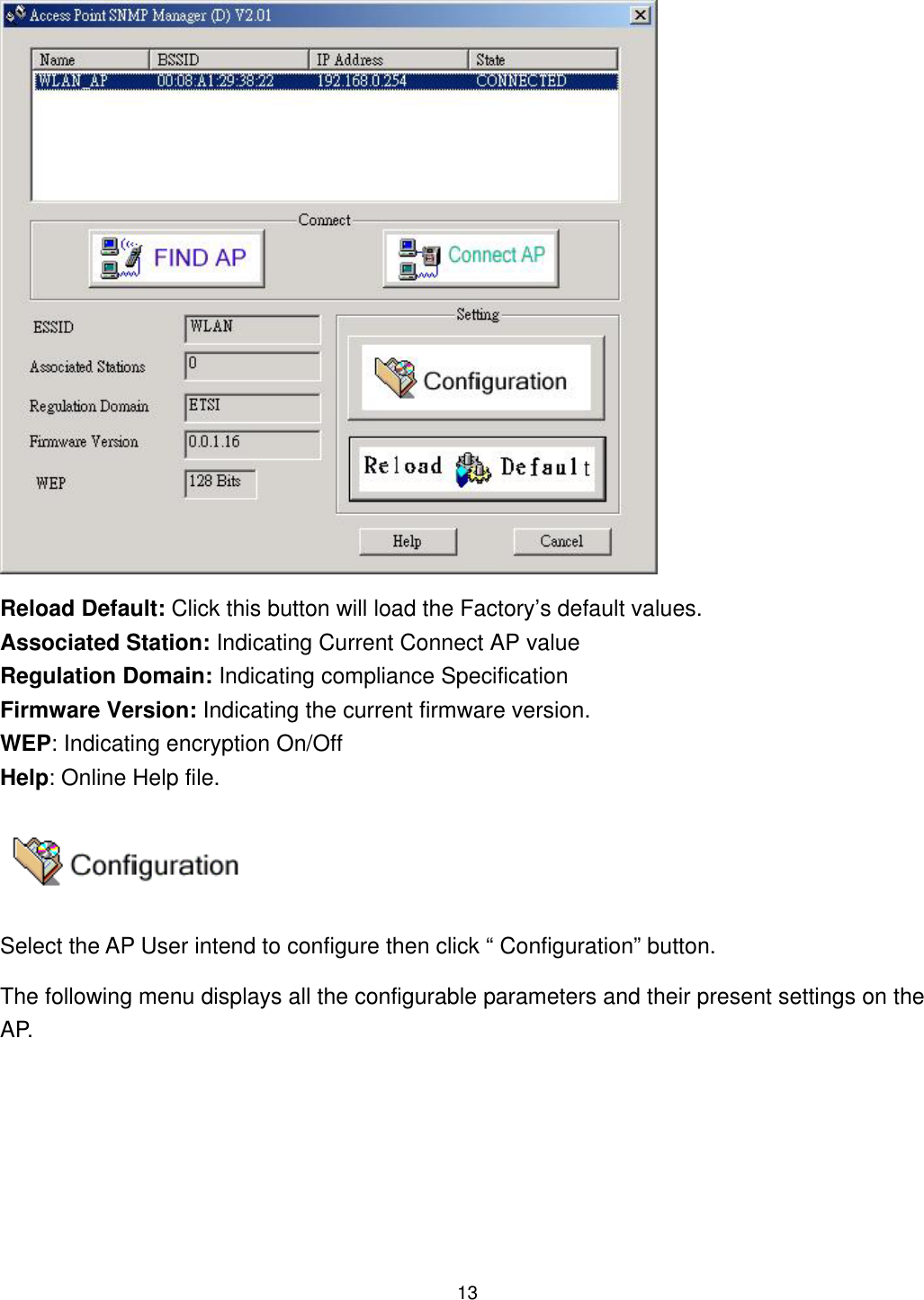
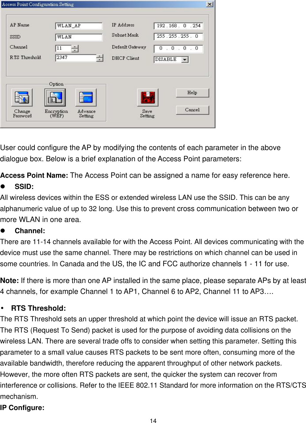
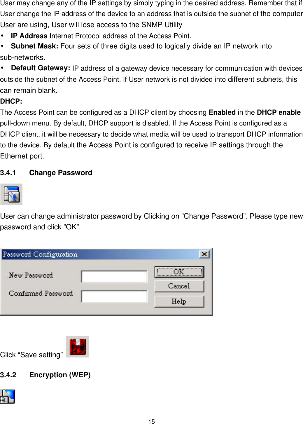
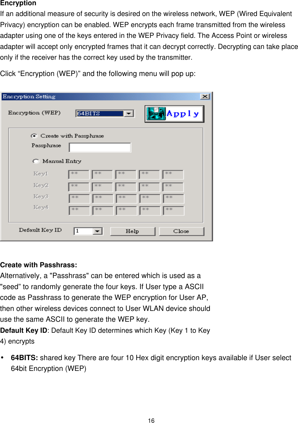
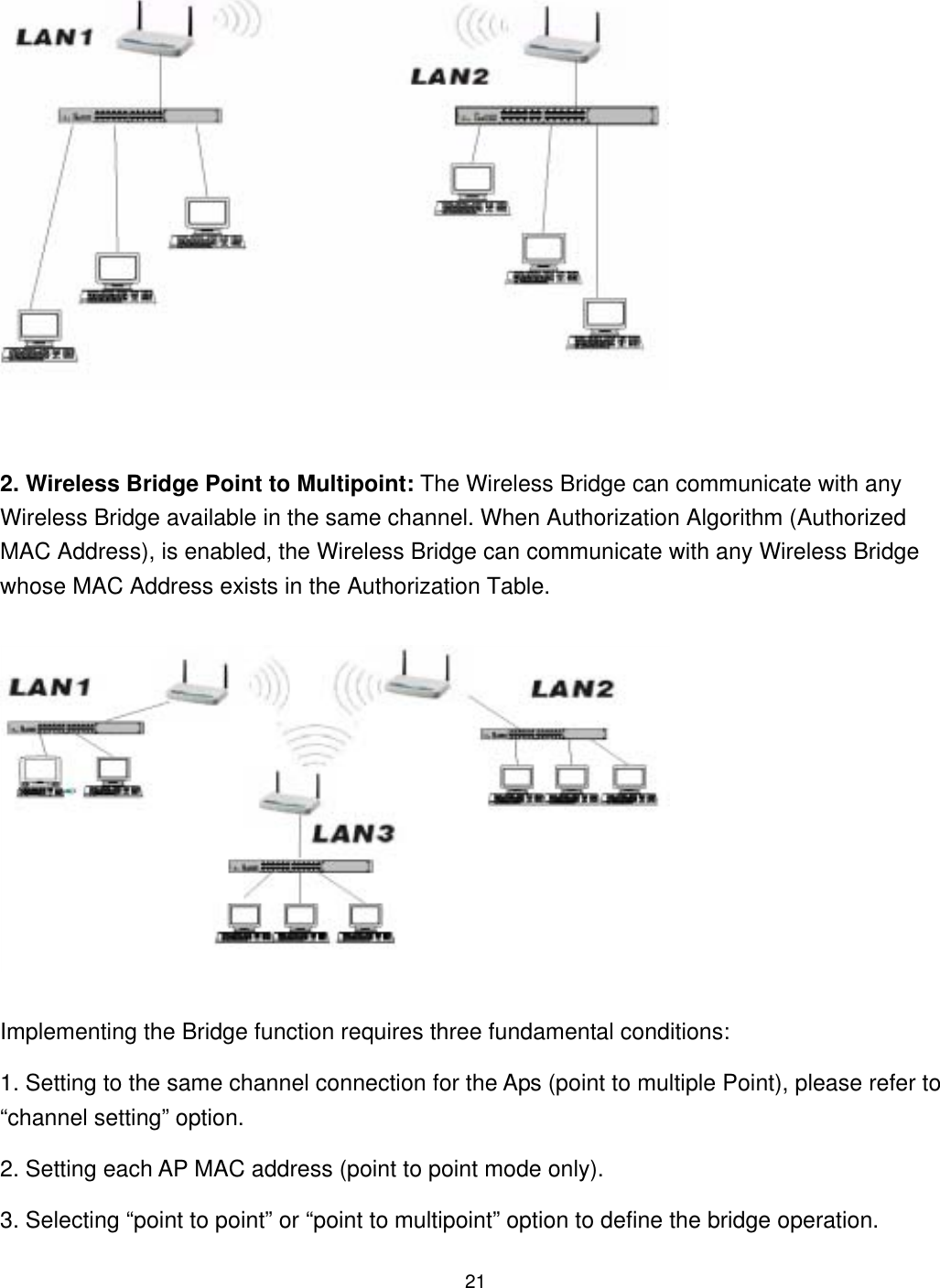
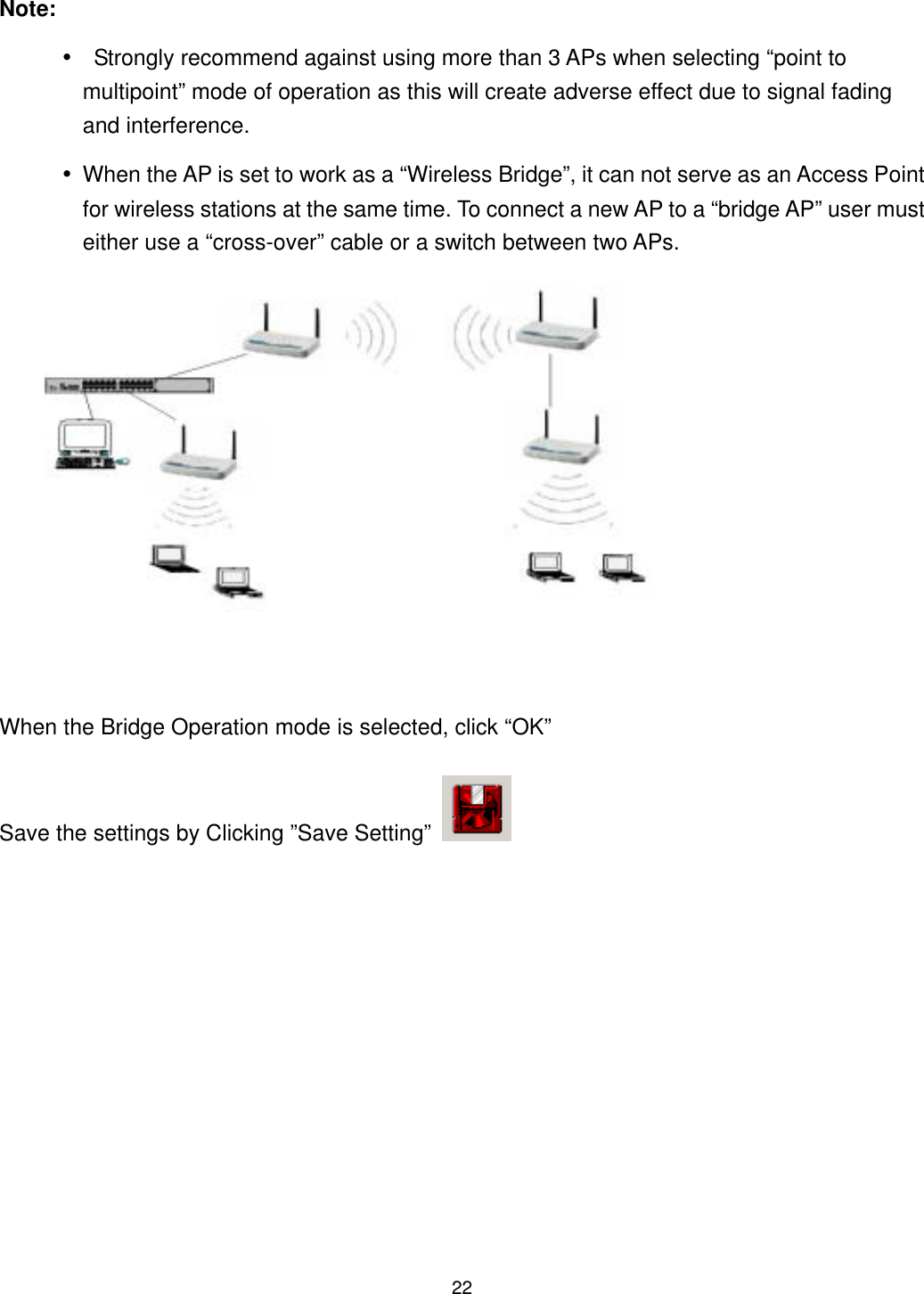
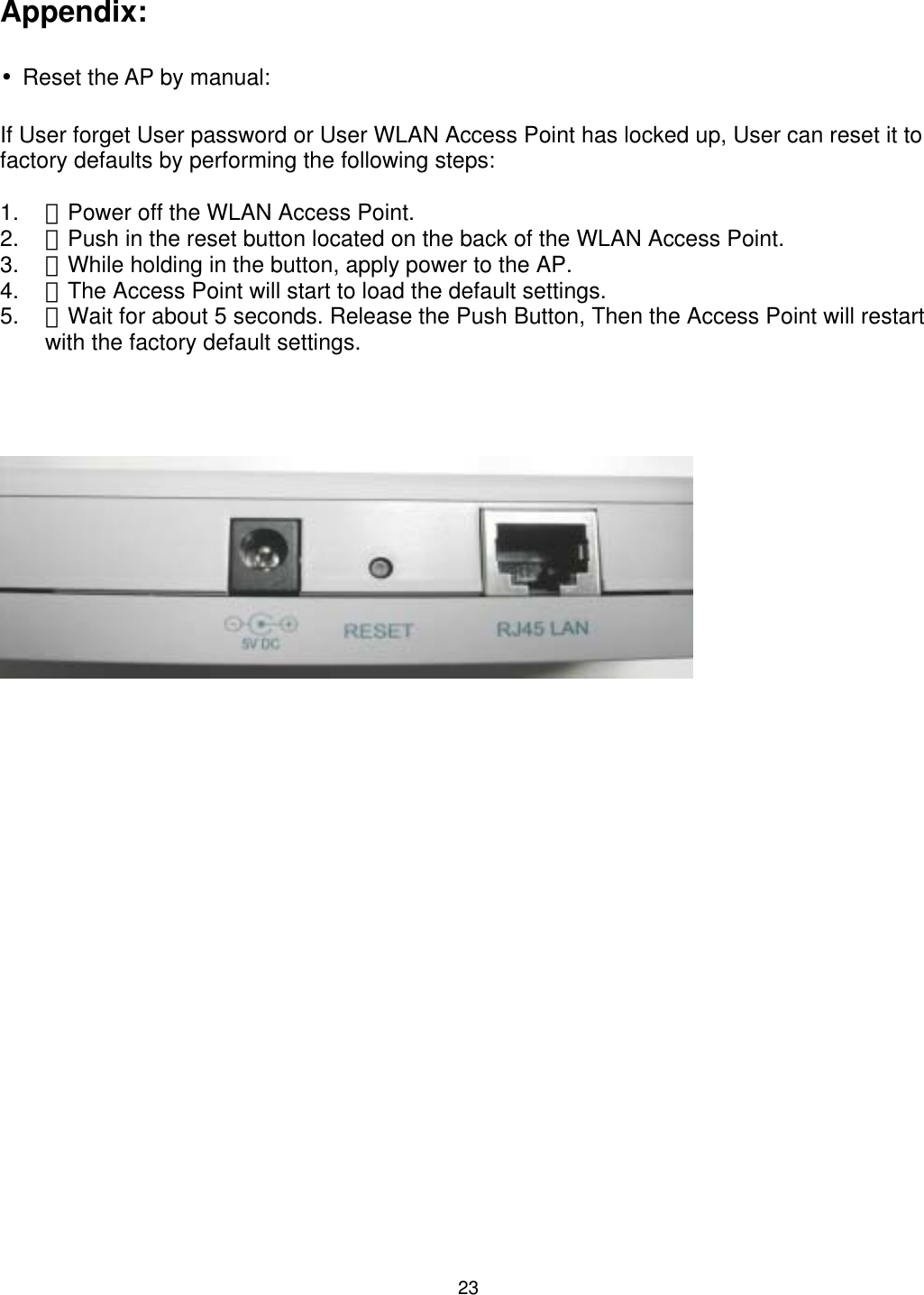
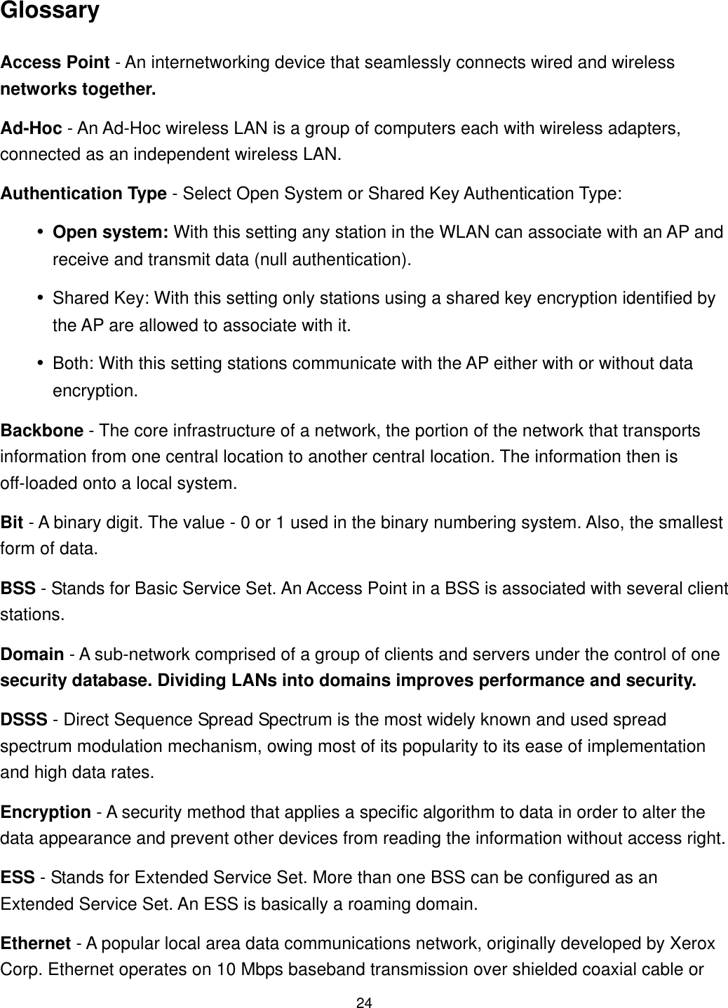
CNet Technology 0252WLAP 11Mbps Wireless Access Point User Manual Manual

CNet Technology Inc 11Mbps Wireless Access Point Manual

Manual

    11Mbps Wireless LAN Access Point  CNAP-711 USER GUIDE
 TABLE OF CONTENTS 1 INTRODUCTION ...............................................................................................................5 1.1 The 11Mbps Wireless Access Point.....................................................................5 1.2 Features ..............................................................................................................5 2 PACKAGE CONTENTS ....................................................................................................6 3 ACCESS POINT CONFIGURATION.................................................................................7 3.1 Hardware installation...........................................................................................7 3.2 Software installation ............................................................................................7 3.3 Configuring the Access Point...............................................................................9 3.3.1 Connecting to the AP....................................................................................9 3.3.2 FIND AP .....................................................................................................10 3.3.3 Connect AP ................................................................................................10 3.4 Configuration.....................................................................................................12 3.4.1 Change Password......................................................................................15 3.4.2 Encryption (WEP).......................................................................................15 3.4.3 Configure “Advance” (Expert setting) .........................................................19 APPENDIX: ............................................................................................................................23 GLOSSARY............................................................................................................................24 4 SPECIFICATIONS...........................................................................................................26  2
 INFORMATION TO USER Federal Communication Commission Interference Statement This equipment has been tested and found to comply with the limits for a Class B digital device, pursuant to Part 15 of the FCC Rules. These limits are designed to provide reasonable protection against harmful interference in a residential installation. This equipment generates, uses and can radiate radio frequency energy and, if not installed and used in accordance with the instructions, may cause harmful interference to radio communications. However, there is no guarantee that interference will not occur in a particular installation. If this equipment does cause harmful interference to radio or television reception, which can be determined by turning the equipment off and on, the user is encouraged to try to correct the interference by one of the following measures: - Reorient or relocate the receiving antenna. - Increase the separation between the equipment and receiver. - Connect the equipment into an outlet on a circuit different from that to which the receiver is connected. - Consult the dealer or an experienced radio/TV technician for help. FCC Caution: To assure continued compliance, (example - use only shielded interface cables when connecting to computer or peripheral devices) any changes or modifications not expressly approved by the party responsible for compliance could void the user's authority to operate this equipment. This device complies with Part 15 of the FCC Rules. Operation is subject to the following two conditions: (1) This device may not cause harmful interference, and (2) this device must accept any interference received, including interference that may cause undesired operation. IMPORTANT NOTE: FCC Radiation Exposure Statement: This equipment complies with FCC radiation exposure limits set forth for an uncontrolled environment. This equipment should be installed and operated with minimum distance 20cm between the radiator & your body. This transmitter must not be co-located or operating in conjunction with any other antenna or transmitter. Regulatory The wireless LAN ACCess Point must be installed and used in strict accordance with the manufacturer’s instructions. This device complies with the following radio frequency and safety standards. USA - Federal Communications Commission (FCC)  3
 This device complies with Part 15 of FCC Rules. Operation is subject to the following two conditions: •This device may not cause harmful interference. •This device must accept any interference that may cause undesired operation. Europe - R&TTE Directive This device complies with the specifications listed below: •ETS 300-826 General EMC requirements for Radio equipment. •ETS 300-328 Technical requirements for Radio equipment. •EN60950 Safety requirements for Radio equipment. EU Countries not intended for use The ETSI version of this device is intended for home and office use in Austria, Belgium, Denmark, Finland, France (with Frequency channel restrictions). Germany, Greece, Ireland, Italy, Luxembourg, Netherlands, Portugal, Spain, Sweden and United Kingdom. The ETSI version of this device is also authorized for use in EFTA member states Iceland, Liechtenstein, Norway and Switzerland.  4
 1 Introduction 1.1 The 11Mbps Wireless Access Point The 11Mbps WLAN Access Point is a long-range, high performance LAN product, which provides Access Point services to a 2.4 GHz RF network and bridges to an Ethernet backbone. This solution offers fast, reliable wireless connectivity with considerable cost savings over wired LANs (which include long-term maintenance overhead for cabling.) Just install enough wireless access points, plug WLAN card into User notebook or WLAN adapter into User desktop PC, and start networking. Using this device in conjunction with WLAN cards or adapters, User can create an instant network that integrates seamlessly with 10Mbps Ethernet LANs. Moreover, moving or expanding User network is as easy as moving or installing additional access points - no wire! 1.2 Features •IEEE 802.11b Direct Sequence spread spectrum high rate compatible. •High data rate 11/5.5/2/1 Mbps. •WEP encryption/decryption is accomplished on the fly. •Fragmentation and Reassembly. •Wired Equivalent Privacy Algorithm (WEP) (64 bits/128 bits) •Power Management. •Passive/Active scan. Long/Short preamble. •RTS/CTS handshake. •Duplicate Detection and Recovery. •Authentication Algorithm (Open System, Shared Key). •Dual external antennas supporting diversity. •Easy installation.  5
 2 Package Contents •One Access Point. •One setup Utility CD-ROM( User Guide on CD). •One power adapter. •Quick Installation Guide.  Quick Installation Guide    6
 3  Access Point Configuration 3.1 Hardware installation Connect the LAN RJ45 port of the Access Point (AP) to a PC, Notebook or User existing network (using Ethernet Cat. 5 cable) and connect the DC power adaptor to the AP. Note: To configure the AP, User can use either the wired Ethernet connection or a Wireless LAN device. 3.2 Software installation Insert the setup CD into the CD-ROM drive of the PC or Notebook used for configuration. There are two methods to install the AP utility software: (a). Auto run: an auto run program will display on the screen. Click “Install Software” (b). Alternately, please click “start\run\D:\AP\utility\setup.exe (D:\ is the default letter for the CD-ROM drive). The InstallShield Wizard will guide User through the installation in the following menu sequence:  7
   Click “Next”.   Choose the default installation file path and click “Next” or click “Change” to select a different location.   Click “Install”                             Click “Finish” to complete the Software installation.  8
 3.3 Configuring the Access Point 3.3.1  Connecting to the AP Click Start/Program/SNMP. Note: The default IP address of the AP is “192.168.0.254”. For connecting to the AP, please assign an IP address (in the range of 192.168.0.1 ~ 192.168.0.253) to the network device used for configuration (Wireless or wired LAN card). The setup program will scan the network for the Access Points installed: When done, the present settings information of all the Access Points on the network will be displayed on the screen as below:  9
 There are two “buttons” displayed by the program, “FIND AP” and “Connect AP”. Their functions are explained below: 3.3.2 FIND AP  Clicking on “FIND AP”, the utility will automatically rescan for all the Access Points (based on IP address) on the network and display their current settings. 3.3.3 Connect AP  Clicking on “Connect AP”, the utility will connect to the selected AP and an “Input PASSWORD” dialogue box will be displayed requesting password entry for the AP being configured:  10
 The AP default PASSWORD is “WLAN”, to initially configure the AP, please type the default password and click ”OK”. Note: Passwords are case sensitive. Upper/lower case characters, space or any symbol will affect PASSWORD recognition. Note: User also can “double click” AP intended for configuration and type the PASSWORD. To configure AP with already known static IP, please type the IP address to connect to the AP.  11
 3.4 Configuration The configuration information display as below:  12
 Reload Default: Click this button will load the Factory’s default values. Associated Station: Indicating Current Connect AP value Regulation Domain: Indicating compliance Specification   Firmware Version: Indicating the current firmware version. WEP: Indicating encryption On/Off   Help: Online Help file.  Select the AP User intend to configure then click “ Configuration” button. The following menu displays all the configurable parameters and their present settings on the AP.  13
 User could configure the AP by modifying the contents of each parameter in the above dialogue box. Below is a brief explanation of the Access Point parameters: Access Point Name: The Access Point can be assigned a name for easy reference here.   SSID: All wireless devices within the ESS or extended wireless LAN use the SSID. This can be any alphanumeric value of up to 32 long. Use this to prevent cross communication between two or more WLAN in one area.   Channel: There are 11-14 channels available for with the Access Point. All devices communicating with the device must use the same channel. There may be restrictions on which channel can be used in some countries. In Canada and the US, the IC and FCC authorize channels 1 - 11 for use. Note: If there is more than one AP installed in the same place, please separate APs by at least 4 channels, for example Channel 1 to AP1, Channel 6 to AP2, Channel 11 to AP3…. •  RTS Threshold:  The RTS Threshold sets an upper threshold at which point the device will issue an RTS packet. The RTS (Request To Send) packet is used for the purpose of avoiding data collisions on the wireless LAN. There are several trade offs to consider when setting this parameter. Setting this parameter to a small value causes RTS packets to be sent more often, consuming more of the available bandwidth, therefore reducing the apparent throughput of other network packets. However, the more often RTS packets are sent, the quicker the system can recover from interference or collisions. Refer to the IEEE 802.11 Standard for more information on the RTS/CTS mechanism. IP Configure:    14
 User may change any of the IP settings by simply typing in the desired address. Remember that if User change the IP address of the device to an address that is outside the subnet of the computer User are using, User will lose access to the SNMP Utility •  IP Address Internet Protocol address of the Access Point. • Subnet Mask: Four sets of three digits used to logically divide an IP network into sub-networks. • Default Gateway: IP address of a gateway device necessary for communication with devices outside the subnet of the Access Point. If User network is not divided into different subnets, this can remain blank. DHCP: The Access Point can be configured as a DHCP client by choosing Enabled in the DHCP enable pull-down menu. By default, DHCP support is disabled. If the Access Point is configured as a DHCP client, it will be necessary to decide what media will be used to transport DHCP information to the device. By default the Access Point is configured to receive IP settings through the Ethernet port.   3.4.1 Change Password  User can change administrator password by Clicking on ”Change Password”. Please type new password and click ”OK”. Click “Save setting”   3.4.2 Encryption (WEP)   15
 Encryption If an additional measure of security is desired on the wireless network, WEP (Wired Equivalent Privacy) encryption can be enabled. WEP encrypts each frame transmitted from the wireless adapter using one of the keys entered in the WEP Privacy field. The Access Point or wireless adapter will accept only encrypted frames that it can decrypt correctly. Decrypting can take place only if the receiver has the correct key used by the transmitter. Click “Encryption (WEP)” and the following menu will pop up:  Create with Passhrass: Alternatively, a "Passhrass" can be entered which is used as a "seed” to randomly generate the four keys. If User type a ASCII code as Passhrass to generate the WEP encryption for User AP, then other wireless devices connect to User WLAN device should use the same ASCII to generate the WEP key. Default Key ID: Default Key ID determines which Key (Key 1 to Key 4) encrypts •  64BITS: shared key There are four 10 Hex digit encryption keys available if User select 64bit Encryption (WEP)  16
 •128BITS: there are four 26 Hex digit encryption keys available if User select 128bit  17
  Make sure to Click    to save all changes. •  NOTE: 64 bit WEP is the same as 40 bit WEP!   The lower level of WEP encryption uses a 40 bit (10 character) “secret key” (set by the user), and a 24 bit “Initialization Vector” (not under user control). The panel allows the entry of four keys for 64-bit encryption and one set for 128-bit key encryption. Each key must consist of hex digits, which means that only digits 0-9 and letters A-F are valid entries. The SNMP Utility will not apply keys that are not entered correctly.  important: At this stage the configuration of the Access Point is complete and AP can be used for regular functions. The following section will go through some advanced features on the AP. It is recommended that novice users consult with networking experts before changing these settings.  18
 3.4.3  Configure “Advance” (Expert setting)  Click the “Advance Settings” button and the following dialogue box will pop up. Click “Yes” to configure AP or “No” to terminate configuration. When “YES” selected, the Advanced Setting dialog box with two functional buttons will be displayed on the screen:   MAC Address Filter Mac address: Unique 48-bit, hard-coded Media Access Control address known as the station identifier. Filtering and Access Control The wireless access point can limit the wireless devices that associate with it and the data packets that are forwarded through it. Filters can provide a degree of security and improve network performance by eliminating broadcast/multicast packets from the radio network. The MAC Address Filter contains the MAC address of every wireless device allowed to associate with the  19
 access point. This prevents unauthorized access to network resources. Click “Save” when finished setting. Click    save setting to save all changes.   Bridge setting (indoors application only): Wireless Bridge Wireless Bridge mode allows two types of connections:  1. WB Point-to-Point: The wireless bridge is configured to communicate with a specific remote MAC address.  20
           2. Wireless Bridge Point to Multipoint: The Wireless Bridge can communicate with any Wireless Bridge available in the same channel. When Authorization Algorithm (Authorized MAC Address), is enabled, the Wireless Bridge can communicate with any Wireless Bridge whose MAC Address exists in the Authorization Table.  Implementing the Bridge function requires three fundamental conditions: 1. Setting to the same channel connection for the Aps (point to multiple Point), please refer to “channel setting” option. 2. Setting each AP MAC address (point to point mode only). 3. Selecting “point to point” or “point to multipoint” option to define the bridge operation.  21
 Note: •  Strongly recommend against using more than 3 APs when selecting “point to multipoint” mode of operation as this will create adverse effect due to signal fading and interference. •When the AP is set to work as a “Wireless Bridge”, it can not serve as an Access Point for wireless stations at the same time. To connect a new AP to a “bridge AP” user must either use a “cross-over” cable or a switch between two APs.   When the Bridge Operation mode is selected, click “OK” Save the settings by Clicking ”Save Setting”    22
 Appendix: •Reset the AP by manual: If User forget User password or User WLAN Access Point has locked up, User can reset it to factory defaults by performing the following steps: 1.  Power off the WLAN Access Point.  2.  Push in the reset button located on the back of the WLAN Access Point.  3.  While holding in the button, apply power to the AP.  4.  The Access Point will start to load the default settings.  5.  Wait for about 5 s econds. Release the Push Button, Then the Access Point will restart     with the factory default settings.    23
 Glossary Access Point - An internetworking device that seamlessly connects wired and wireless networks together. Ad-Hoc - An Ad-Hoc wireless LAN is a group of computers each with wireless adapters, connected as an independent wireless LAN. Authentication Type - Select Open System or Shared Key Authentication Type: •Open system: With this setting any station in the WLAN can associate with an AP and receive and transmit data (null authentication). •Shared Key: With this setting only stations using a shared key encryption identified by the AP are allowed to associate with it. •Both: With this setting stations communicate with the AP either with or without data encryption. Backbone - The core infrastructure of a network, the portion of the network that transports information from one central location to another central location. The information then is off-loaded onto a local system. Bit - A binary digit. The value - 0 or 1 used in the binary numbering system. Also, the smallest form of data. BSS - Stands for Basic Service Set. An Access Point in a BSS is associated with several client stations. Domain - A sub-network comprised of a group of clients and servers under the control of one security database. Dividing LANs into domains improves performance and security. DSSS - Direct Sequence Spread Spectrum is the most widely known and used spread spectrum modulation mechanism, owing most of its popularity to its ease of implementation and high data rates. Encryption - A security method that applies a specific algorithm to data in order to alter the data appearance and prevent other devices from reading the information without access right. ESS - Stands for Extended Service Set. More than one BSS can be configured as an Extended Service Set. An ESS is basically a roaming domain. Ethernet - A popular local area data communications network, originally developed by Xerox Corp. Ethernet operates on 10 Mbps baseband transmission over shielded coaxial cable or  24
 over shielded twisted pair copper wire. Firmware - Code that is written onto read-only memory (ROM) or programmable read-only memory (PROM). Once firmware has been written into the ROM or PROM, it is retained even when the device is turned off. Fragmentation - Breaking a packet into smaller units when transmitting over a network medium that cannot support the original size of the packet. Infrastructure - An integrated wireless and wired LAN is called an infrastructure configuration. IRQ - Interrupt Request, a hardware interrupt on a PC. There are 16 IRQ lines used to signal the CPU that peripheral event has started or terminated. In most cases, two devices cannot use the same interrupt line. PCMCIA - Personal Computer Memory Card International Association, which develops standards for PC cards, formerly known as PCMCIA cards, are available in three types which are about the same length and width as credit cards, but range in thickness from 3.3mm(Type I), 5.0mm(Type II), to 10.5mm(Type III). These cards can be used for many functions, including memory storage, as modem cards, wireless LAN cards or Wired LAN cards. Roaming - A function that allows one to travel with a mobile end system (wireless LAN mobile station, for example) through the territory of domain(an ESS, for example) while continuously connecting to the infrastructure.  25
 4 Specifications   IEEE 802.11 DS 11Mbps Access Point LAN Standard  IEEE 802.3 for 10BASE-T Protocol  Wireless clients IEEE 802.11b Frequency Band  2400 ~ 2483.5MHz ( for US, Canada, and ETSI) 2400 ~ 2497MHz (for Japan) Modulation TYPE  CCK,BPSK,QPSK Operating Channels  IEEE 802.11 compliant 11 channels (US, Canada) 13 channels (ETSI) 14 channels (Japan) Radio Technology  Direct Sequence Spread Spectrum Data Rate  1 / 2 / 5.5 / 11 Mbps per Channel Output Power  +18dBm +/- 2dBm Receive sensitivity  Min. -80dBm for 11Mbps    (@10E-5 BER) -81 Min. -82dBm for 5.5/2/1 Mbps (@10E-5 BER) -85 Wired interface  Ethernet IEEE 802.3 10BASE-T LEDs  Power, Link Status Antenna Type  Dipoles antenna Power Supply  Input: 100~120V, 220~240V AC, 50~60Hz Output: 5V DC, 2.1A Power Consumption  Tx Power consumption: < 700mA (Max.) <600mA Rx Power consumption: < 580mA (Max.) <560mA Dimensions  85mm x 28mm x 145mm 3.35 x 1.22 x 5.71 inch Certification  Radio:   EU: ETS 300 328; USA: FCC Part 15C Taiwan: DGT EMC:        EU ETS 300 826; USA: FCC Part 15B Safety:  EN60950 Network Management  Windows 95/98/NT/2000/XP SNMP Utility   26

Navigation menu