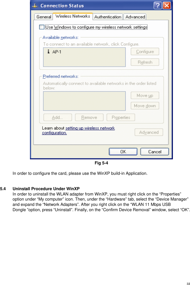
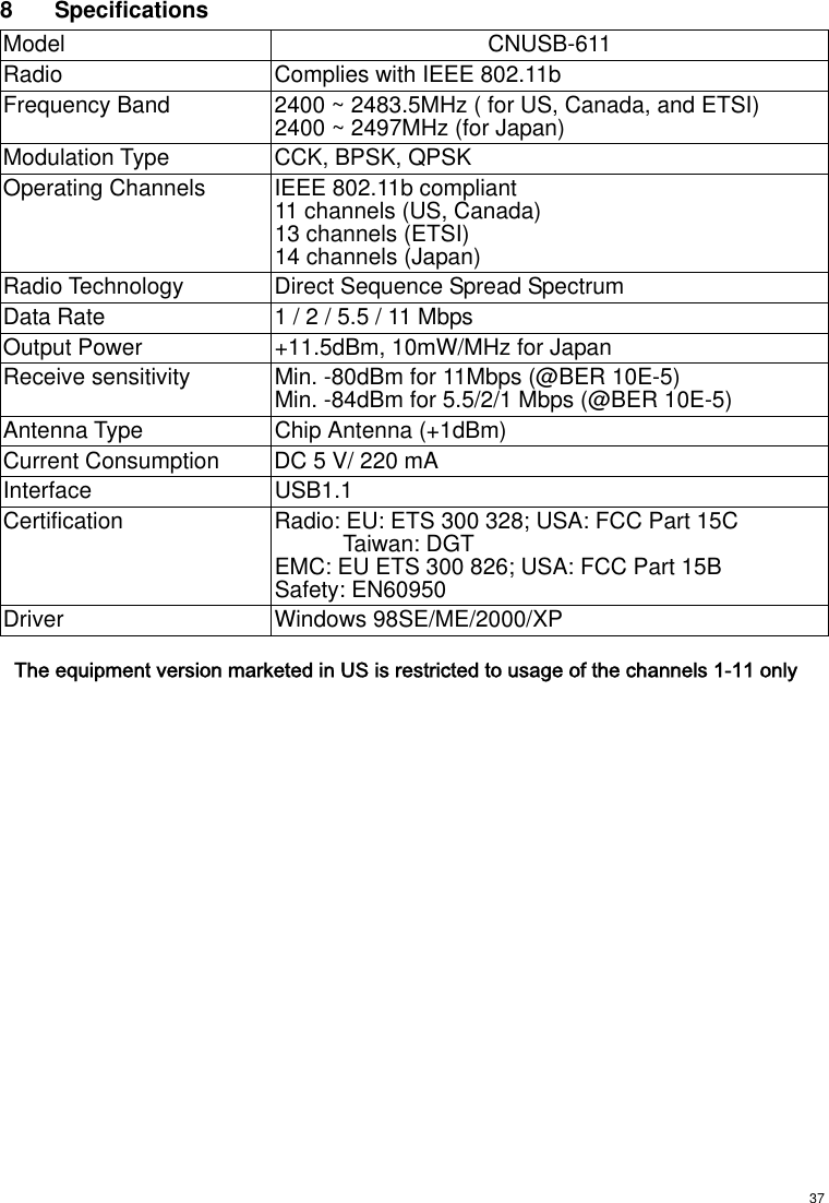
CNet Technology 0343UD 11Mbps WLAN USB Dongle User Manual

CNet Technology Inc 11Mbps WLAN USB Dongle

user manual

     User Guide  11Mbps Wireless LAN USB Dongle   Version 2.0
Federal Communication Commission Interference Statement This equipment has been tested and found to comply with the limits for a Class B digital device, pursuant to Part 15 of the FCC Rules.  These limits are designed to provide reasonable protection against harmful interference in a residential installation.  This equipment generates, uses and can radiate radio frequency energy and, if not installed and used in accordance with the instructions, may cause harmful interference to radio communications.  However, there is no guarantee that interference will not occur in a particular installation.  If this equipment does cause harmful interference to radio or television reception, which can be determined by turning the equipment off and on, the user is encouraged to try to correct the interference by one of the following measures:  - Reorient or relocate the receiving antenna. - Increase the separation between the equipment and receiver. - Connect the equipment into an outlet on a circuit different from that to which the receiver is connected. - Consult the dealer or an experienced radio/TV technician for help.  This device complies with Part 15 of the FCC Rules. Operation is subject to the following two conditions: (1) This device may not cause harmful interference, and (2) this device must accept any interference received, including interference that may cause undesired operation.  FCC Caution: Any changes or modifications not expressly approved by the party responsible for compliance could void the user's authority to operate this equipment.  IMPORTANT NOTE: FCC Radiation Exposure Statement: This equipment complies with FCC radiation exposure limits set forth for an uncontrolled environment. End users must follow the specific operating instructions for satisfying RF exposure compliance.  This transmitter must not be co-located or operating in conjunction with any other antenna or transmitter.
Europe - R&TTE Directive This device complies with the specifications listed below: ¨ ETS 300-826 General EMC requirements for Radio equipment. ¨ ETS 300-328 Technical requirements for Radio equipment. ¨ EN60950 Safety requirements for Radio equipment.  EU Countries not intended for use The ETSI version of this device is intended for home and office use in Austria, Belgium, Denmark, Finland, France (with Frequency channel restrictions). Germany, Greece, Ireland, Italy, Luxembourg, Netherlands, Portugal, Spain, Sweden and United Kingdom.  The ETSI version of this device is also authorized for use in EFTA member states Iceland, Liechtenstein, Norway and Switzerland.
 4TABLE OF CONTENTS 1 INTRODUCTION.......................................................................6 1.1 The 11Mbps Wireless LAN USB Dongle ......................................6 1.2 Feature.......................................................................................... 6 1.3 Hardware Description ................................................................... 6 1.4 Package Contents......................................................................... 6 1.5 System Requirements................................................................... 7 2 NETWORK CONFIGURATION AND PLANNING ....................8 2.1 Wireless LAN Basic ...................................................................... 8 2.2 Network Topology ......................................................................... 8 2.3 Roaming......................................................................................10 3 INSTALLING THE DRIVERS AND CONFIGURATION UTILITY FOR WIN98SE, ME, 2000.............................................................. 11 3.1 Running the Auto Driver/Utility Installation.................................. 11 3.2 Inserting the Dongle.................................................................... 17 4 CONFIGURATION UTILITY....................................................21 4.1 Using the configuration Utility .....................................................21 4.1.1 Status .................................................................................21 4.1.2 Statistics .............................................................................23 4.1.3 Site Survey......................................................................... 24 4.1.4 Encryption .......................................................................... 24 4.1.5 Advanced ........................................................................... 25 4.1.6 Profiles ...............................................................................27 4.1.7 About.................................................................................. 27 4.2 How to Uninstall the configuration & Monitor Utility....................28 5 INSTALLATION PROCEDURE UNDER WINDOWS XP........30
 55.1 About Windows XP .....................................................................30 5.2 Installing the Driver .....................................................................30 5.3 Configuration Under WinXP........................................................30 5.4 Uninstall Procedure Under WinXP..............................................33 6 TROUBLESHOOTING............................................................34 6.1 Adapter Installation Problems..................................................... 34 6.2 Network Connection Problems ...................................................34 7 GLOSSARY............................................................................35 8 SPECIFICATIONS ..................................................................37
 61 Introduction 1.1  The 11Mbps Wireless LAN USB Dongle The 11Mbps Wireless LAN USB Dongle now has a new, higher-powered antenna that provides a greater range than ever. The increased sensitivity helps filter out interference and notice to keep your signal clear. Improved error correction in the chipset keeps you operating at higher transmission rates for longer distances. And since you only need USB ports, you’re free to use your other ports for additional accessories. Plug-and-Play device, Windows 98SE/ME/2000/XP will automatically recognize the USB wireless LAN Dongle and initiate the installation process. Upon successful installation, the USB wireless LAN Dongle will communicate seamlessly with other wireless home and office networking products. Using radio frequency (RF) technology, WLANs transmit and receive data over the air, minimizing the need for wired connections. Thus, WLANs combine data connectivity with user mobility, and through simplified configuration, enable movable LANs. This wireless networking solution has been designed for both large and small businesses, and it is scalable so that you can easily add more users and new network features as your business grows. This manual will assist you in the installing WLAN USB Dongle. 1.2 Feature  IEEE 802.11b Direct Sequence high rate compatible.  High data rate 11/5.5/2/1 Mbps.  Auto Rate fallback for optimizing communication possibility in worse channel conditions and over larger distances.  Wired Equivalent Privacy Algorithm (WEP) (64 bits/128 bits) Support USB 1.1 interface Compliant with Windows 98SE/2000/ME/XP Power save in infrastructure mode. Build-in chip antenna Easy-to-Use Graphical Configuration utility saves detailed connectivity profiles for frequently accessed networks Plug-and-Play and easy setup 1.3 Hardware Description The Wireless LAN USB Dongle supports an 11 Mbps half-duplex connection to Ethernet networks. This Dongle is fully compliant with 2.4G DSSS wireless networking as defined in IEEE 802.11b. It can be installed in any notebook and desktop with a USB port, and is currently provided for Windows 98SE/ME/2000/XP. 1.4 Package Contents One 11Mbps Wireless LAN USB Dongle. One setup Utility CD-ROM(User Guide on CD). Quick Installation Guide.
 7  11Mbps Wireless LAN USB Dongle  (USB Cable)    Quick Installation Guide Setup Utility CD-ROM  Quick Installation Guide  1.5 System Requirements An available USB port.  USB 1.1(12 Mbps) or USB 2.0(480 Mbps) ports ready.  Operating System: Windows 98SE, ME, 2000, or XP.  2M bytes free disk space for utility and driver installation.
 82  Network Configuration and Planning 2.1  Wireless LAN Basic The adapter supports legacy Ethernet LAN network configuration options as defined by the IEEE 802.11b standards committee. The adapter can be configured as:  Ad-Hoc for departmental or SOHO LANs.  Infrastructure for enterprise LANs.  LAN-Interconnection for point-to-point link as campus backbone. 2.2 Network Topology  Fig 2-1 Ad-Hoc Wireless LAN An Ad-Hoc wireless LAN is a group of computers, each equipped with one WLAN adapter, connected as an independent wireless LAN. Computers in a specific Ad-Hoc wireless LAN must be configured to share the same radio channel.
 9Fig 2-2 Infrastructure Wireless LAN The adapter provides access to a wired LAN for wireless workstations. An integrated wireless and wired LAN is called an infrastructure configuration. A group of adapter PC users and an Access Point compose a Basic Service Set (BSS). Each adapter PC in a BSS can talk to any computer in the wired LAN infrastructure via the Access Point. An infrastructure configuration extends the accessibility of a adapter equipped PC to a wired LAN, and doubles the effective wireless transmission range for 2 adapter PCs. Since the Access Point is able to forward data within its BSS, the effective transmission range in an infrastructure LAN is double.  Fig 2-3 The effective transmission range The use of a unique ID in a BSS is essential. All adapter equipped PCs configured without roaming options in independent BSS must be configured with a BSS ID corresponding to the Access Point used in the BSS. Check your Access Point for its BSS ID or use the Access Point Browser Utility program to determine the BSS ID
 10The infrastructure wireless LAN configuration is appropriate for enterprise-scale wireless access to a central database, or as a wireless application for mobile users. 2.3 Roaming  Fig 2-4 Roaming in an Extended Service Set (ESS) Infrastructure mode also supports roaming capabilities for mobile users. More than one BSS can be configured as an Extended Service Set (ESS). The continuous network allows users to roam freely within an ESS. All adapter PCs and Access Point within one ESS must be configured with the same ESS ID. Before enabling an ESS with roaming capability, it is recommended to select a feasible radio channel and optimum Access Point position. Proper Access Point positioning combined with a clear radio signal will greatly enhance performance.
 113  Installing the Drivers and Configuration Utility for Win98SE, ME, 2000  3.1  Running the Auto Driver/Utility Installation Before installing your card, insert the Auto-Install CD into your CD-ROM driver. Unless you have deactivated the auto-run feature of Windows, the screen shown in Fig 3-1 should appear automatically. If this screen doesn’t appear automatically, you can access the installation by clicking the Start button and choosing Run. In the drop-down box provided type D:\Setup.exe (where D: is the letterof your CD-ROM drive). Alternately, double-click My Computer and double-click the   Setup.exe iconin the folder that appears.   Fig 3-1 Auto-run feature of Windows 1. Click “Windows 98SE/ME/2000/XP Driver & Utility - USB” to install driver/utility for your USB WLAN Dongle. You will see Welcome to the InstallShield Wizard for 802.11 Wireless LAN. Click“Next >” (Fig 3-2). 2. After clicking “Next >”, components’ version of package will be shown on this screen. (Fig 3-3).
 12   Fig 3-2 Install WLAN Driver / Utility
 13 Fig 3-3 Components Version 3. The installation provides you to install package Custom or Typical. (Fig 3-4) 4. If “Custom” be chosen, you can select package individually. If you choose “Typical”, The 4 packages will be installed in your system. (Fig 3-5)
 14 Fig 3-4 Setup Type
 15 Fig 3-5 Typical Setup   5. You can specify a folder name of this program(Fig 3-6) 6. After copying files, you can finish the installation(Fig 3-7)
 16 Fig 3-6 Select Program Folder
 17 Fig 3-7 Finish  3.2  Inserting the Dongle  To insert the wireless LAN USB Dongle adapter into a notebook or desktop computer, do the following: 1. Select an available USB port on the notebook or desktop PC. 2. Insert the USB Dongle adapter into the USB port.     Fig 3-9 Hardware insert
 18 After installing USB WLAN Adapter driver and utility. Please insert the WLAN USB Dongle. You will see Found New Hardware. Please select “Install the software automatically” then click “Next>” (Fig 3-10). The screen in Windows XP (Fig 3-11) will appear click “Continue Anyway”. The Windows has finished installing software for the device. Click “Finish” to finish the installation.(Fig 3-12). Configuration Utility please see Chapter 4   Fig 3-10 Found New Hardware
 19 Fig 3-11 Windows XP Screen
 20 Fig 3-12 Finish the installation
 214 Configuration Utility The Configuration Utility is provided to allow you further customization of the WLAN USB Dongle and your wireless network. 4.1  Using the configuration Utility After the Configuration Utility has been installed, an icon will placed in the system tray (next to click button of your screen) when the WLAN PC Card is inserted, as shown in Fig 4-1.  Fig 4-1 The utility is divided into six parts: Status, Statistics, Site Survey, Encryption, Advanced, and Info. You should change all your configuration settings for your WLAN PC Card using this utility and not with the Network Properties section in your Control Panel. 4.1.1 Status The Status screen (Shown in Fig 4-2) provides information about the current link between the Network PC Card and Wireless Access Point. When in Infrastructure Mode, Status will display the connection statistics for the network segment that you are on. The Channel field shows to what channel the WLAN PC Card is set. The SSID field shows the current SSID set for the wireless network. This SSID can be modified at you click Change buttom. The Tx Rate field shows the transfer rate in megabits per second. The Int. Roaming field shows to use this feature to allow your Dongle to retrieve country information from the access point and behave according to that country’s regulations. The Radio field shows on / off radio signal
 22 Fig 4-2  NOTE: When in Ad-Hoc mode, Signal Strength and Link Quality indicators will not be available.  The Signal Strength field will display a bar indicating the percentage, between 0 and 100 percent, of the strength of the signal. The higher the percentage, the stronger the signal. The Link Quality field will display a bar indicating the percentage, between 0 and 100 percent, of the quality of the link. The higher the percentage, the better the link. The Change buttom, allows you to customize the settings for the WLAN PC Card and your wireless network. The Operating Mode setting determines the architecture of your wireless network select Ad-Hoc or Infrastructure Mode depending on your network type. The Ad-Hoc mode is used for simple peer-to-peer network and allows the sharing of local resources only between Network Wireless Adapter without needing a Wireless Access Point. The Infrastructure mode allows a wireless network to be integrated into an existed, wired network through an Access Point. Infrastructure networks permit roaming between Access Points while maintaining a connection to all network resources. An acronym for Service Set Identifier, SSID is the unique name shared among all points in a wireless network. The SSID must be identical for all points in the network. It is case sensitive
 23and must not exceed 32 characters. The Tx Rate field shows the current transfer rate for the Wireless Network USB Dongle. To optimize performance and range, the Tx Rate should be set to Auto, which will automatically adjust the transfer speed for best performance and longest range. The Channel setting specifies the channel used in wireless communication and should be set to the same channel as the other points in the wireless network. The setting can only be adjusted in Ad-Hoc mode. 4.1.2 Statistics The Statistics screen (Shown in Fig 4-3) provides information about the Tx / Rx Data, Management, rejected Packets.  Fig 4-3
 24 Fig 4-4 4.1.3 Site Survey The Site Survey screen shows the available access point and their features. Click on the desired access point. Then double click BSSID to connect or Re-Scan to search for more access points. (Shown in Fig 4-4) 4.1.4 Encryption On the Encryption screen, show in Fig 4-5, you can set the level of security with which you will be using the WLAN PC Card. Under the drop-down box, you can choose to have WEP encryption Disabled, 64-Bit, or 128-Bit Wired Equivalent Privacy (WEP) is an encryption scheme use to protect wireless data communication. If you decide to use encryption, you can choose any of the available WEP keys (1 to 4). The Disabled setting prevents the sharing of data with other computers on the WEP network. When Enable encryption for the WEP Key entry, enter the hexadecimal number (the letters “A” through “F” and the numbers “0” through “9”) set by the other wireless WEP settings; these settings must be identical to the WEP encryption on all points in your wireless network in order to network to your WLAN USB Dongle. The security keys are four 10 digit key for the 64-Bit WEP setting and four 26 digit key for the 128-Bit WEP setting.
 25 Fig 4-5 NOTE: The WEP Key Entry must match the Key on all other devices on the wireless network or this device will be unable to transmit or receive data.  For Authentication Type, you may choose among Auto, Open System or Shared Key.  Shared Key is when both the sender and recipient share a secret key. Both units this key for an extended length of time, sometimes indefinitely. Any eavesdropper that discovers the key may decipher all packets unit the key is changed. Open System the default setting, is when the sender and the recipient do not share a secret key. Each party generates its own key-pair and asks the receiver to accept the (usually randomly) generated key. Once accepted, this key is use for short time only: then a new key is generated and agrees upon. 4.1.5 Advanced The Advanced screen (Fig 4-6) allows you to set Fragmentation Threshold, the RTS/CTS Threshold, and the Preamble Type. The Fragmentation Threshold Value indicates how much of the network resources is devoted to recovering packet errors. The value should remain at its default setting of 2,346. If you experience high packet error rates, you can decrease this
 26value but it will likely decrease overall network performance. Only minor modifications of this value are recommended.  Fig 4-6 The RTS Threshold Value should remain at its default setting of 2,347. A preamble is a signal used to synchronize the transmission timing between two or more systems. A series of transmission pulses is sent before the data to indicate that “someone is about transmit data.” this ensures that systems receive the information correctly when the data transmission starts. The Preamble Type should be set to Short (if the network environment is “noisy”) or Long (if the environment is “clear”) Click Submit to complete the configuration.  Power Save, you can select enabled then submit to allow your adapter to go to sleep mode while theadapter doesn’t precede the data transmission. Or select disabled to make the adapter nevergo to sleep mode. Click submit to save the settings.
 274.1.6 Profiles The Profiles screen (Fig 4-7) allows you can manage the profiles that you have created for the wireless network at home, office and in public places. You can create New file for Save a profile orDelete and Rename the profiles.   Fig 4-7  4.1.7 About The About screen (Fig 4-8) shown the release information for the Driver Version, Firmware Version, Application Version, and MAC Address. Use the “Exit” button in order to exit the application.
 28 Fig 4-8 4.2  How to Uninstall the configuration & Monitor Utility In order to uninstall the Configuration & Monitor Utility from Windows 98SE/ME/2000/XP, you can RUN Setup utility again then you will see Fig 4-7 then step by step remove all installed components. It is recommended to stop the WLAN USB Dongle and “Exit” the application prior to staring the uninstallation procedure.
 29 Fig 4-8
 305  Installation Procedure Under Windows XP Use the procedures described in this section to install and configure the WLAN Dongle under MS Windows XP 5.1  About Windows XP Throughout this section it is assumed that you have a basic working knowledge of WinXP. However, in this paragraph, some specific feature of WinXP are briefly explained. WinXP operating system supports the “Plug & Play” feature. That means that once you insert the WLAN Dongle into your PC for the very first time, the operating system will detect the card and automatically install the driver. Furthermore WinXP supports “Hot Swapping”. with this feature, you can remove and reinsert the card whenever you want. 5.2  Installing the Driver The following selection please check Chapter 3 to setup your WLAN adapter  5.3  Configuration Under WinXP There are two ways to configure WLAN Adapter. One is WLAN Monitor Utility; the other one is Windows Wireless Network Configuration. Use Windows Wireless Network Configuration: Please follow the steps to Enable Select an available networks (Fig 5-1) and click Advanced button (Fig 5-2). Make sure “Use Windows to configure my wireless network settings” is checked and click OK (Fig 5-3). Otherwise unckeck for using WLAN Monitor Utility to setup WLAN (Fig 5-4).    Fig 5-1
 31 Fig 5-2
 32 Fig 5-3
 33 Fig 5-4  In order to configure the card, please use the WinXP build-in Application.  5.4  Uninstall Procedure Under WinXP In order to uninstall the WLAN adapter from WinXP, you must right click on the “Properties” option under “My computer” icon. Then, under the “Hardware” tab, select the “Device Manager” and expand the “Network Adapters”. After you right click on the “WLAN 11 Mbps USB Dongle ”option, press “Uninstall”. Finally, on the “Confirm Device Removal” window, select “OK”.
 346 Troubleshooting 6.1  Adapter Installation Problems If your computer can not find the WLAN USB Adapter or the network driver doesn’t install correctly, check the following: Make sure the Dongle is securely seated in the USB port. When you insert the wireless Dongle into the notebook’s slot, a beep should be heard if the Dongle is properly inserted. Check for any hardware problems, such as physical damage to the card’s connector. Try the card in another USB port. If this also fails, test your computer with another WLAN PC Card that is known to operate correctly. When operating under Windows NT, WLAN adapter does not support in this OS. Make sure your computer is using the latest BIOS. If there are other network adapters in the computer, they may be causing conflict. Remove all other adapters from the computer and test the wireless adapter separately. Check for a defective computer or USB port by trying the USB Dongle in another computer that is known to operate correctly. 6.2  Network Connection Problems If the LED on the USB Dongle does not light, or if you can not access any network resources from the computer. Check the following: Make sure the correct software driver is installed for your operating system. If necessary, try reinstalling the driver. Make sure the computer and other network devices are receiving power. The Access Point you want to attach to may be defective. Try using another Access Point. If you can not access a Windows or NetWare service on the network, check that you have enabled and configured the service correctly. If you can not connect to particular server, be sure that you have access rights and a valid ID and password. If you can not access the Internet, be sure you have configured your system for TCP/IP. If your wireless station can not communicate with a computer in the Ethernet LAN when configured for Infrastructure mode, Check the following: ⌧Make sure the Access Point that the station linked is power on. ⌧If you still can not connect, change the Access Point to another radio channel. ⌧Make sure the BSS ID is the same as the Access Point for a station with roaming disabled, or the SSID is the same as the Access Point for station with roaming enabled. ⌧Ensure that the station is configured with the same security options as the Access Point.
 357 Glossary Access Point - An internetworking device that seamlessly connects wired and wireless networks together.  Ad-Hoc - An Ad-Hoc wireless LAN is a group of computers each with wireless adapters, connected as an independent wireless LAN.  Backbone - The part of a network that connects most of the systems and networks together and handles the most data.  Bit - A binary digit. The value - 0 or 1 used in the binary numbering system. Also, the smallest form of data.  BSS - Stands for Basic Service Set. An Access Point associated with several stations.  Domain - A subnetwork comprised of a group of clients and servers under the control of one security database. Dividing LANs into domains improves performance and security.  DSSS - Direct Sequence Spread Spectrum is very widely known and the most used of the spread spectrum types, owing most of its popularity to its ease of implementation and high data rates.  Encryption - A security method that applies a specific algorithm to data in order to alter the data’s appearance and prevent other devices from reading the information  ESS - Stands for Extended Service Set. More than one BSS can be configured as an Extended Service Set. An ESS basically a roaming domain.  Ethernet - A popular local area data communications network, originally developed by Xerox Corp., which accepts transmission from computers and terminals. Ethernet operates on 10 Mbps baseband transmission over shielded coaxial cable or over shielded twisted pair telephone wire.  Firmware - Code that is written onto read-only memory (ROM) or programmable read-only memory (PROM). Once firmware has been written onto the ROM or PROM, it is retained even when the device is turned off.  Fragmentation- Breaking a packet into smaller units when transmitting over a network medium that cannot support the original size of the packet.  Infrastructure - An integrated wireless and wired LAN is called an infrastructure configuration.  IRQ - Interrupt ReQuest, A hardware interrupt on a PC. There are 16 IRQ lines used to signal the CPU that peripheral event has started or terminated. In most cases, two devices cannot use the same line.  PCMCIA - Personal Computer Memory Card International Association, which develops standards for PC cards, formerly known as PCMCIA cards, are available in three types which are about the same length and width as credit cards, but range in thickness from 3.3mm(Type I), 5.0mm(Type II), to 10.5mm(Type III).   These cards can be used for many functions, including memory storage, as landline modems and as wireless LAN.
 36 Roaming - A function that allow one to travel with a mobile end system (wireless LAN mobile station, for example) through the territory of domain(an ESS, for example) while continuously connecting to the infrastructure.  RTS - Request to Send, An RS-232 signal sent from the transmitting station to the receiving station requesting permission to transmit.  Throughput - The amount of data moved successfully from one place to another in a given time period.  Tx Rate - Transmission Rate.  WEP - Wired Equivalent Privacy, A data privacy mechanism based on a 64-bit or 128-bit shared key algorithm, as described in IEEE 802.11 standard.
 378 Specifications Model CNUSB-611 Radio Complies with IEEE 802.11b Frequency Band 2400 ~ 2483.5MHz ( for US, Canada, and ETSI) 2400 ~ 2497MHz (for Japan) Modulation Type CCK, BPSK, QPSK Operating Channels IEEE 802.11b compliant 11 channels (US, Canada) 13 channels (ETSI) 14 channels (Japan) Radio Technology Direct Sequence Spread Spectrum Data Rate 1 / 2 / 5.5 / 11 Mbps Output Power +11.5dBm, 10mW/MHz for Japan Receive sensitivity Min. -80dBm for 11Mbps (@BER 10E-5) Min. -84dBm for 5.5/2/1 Mbps (@BER 10E-5) Antenna Type Chip Antenna (+1dBm) Current Consumption  DC 5 V/ 220 mA Interface USB1.1 Certification Radio: EU: ETS 300 328; USA: FCC Part 15C Taiwan: DGT EMC: EU ETS 300 826; USA: FCC Part 15B Safety: EN60950 Driver Windows 98SE/ME/2000/XP   The equipment version marketed in US is restricted to usage of the channels 1-11 only
 38                        FCC WARNING This equipment has been tested and found to comply with the limits for a Class A computing device pursuant to Part 15 of FCC Rules, which are designed to provide reasonable protection against electromagnetic interference in a commercial environment. Changes or modifications to the equipment not expressly approved by the party responsible for compliance could void the user's authority to operate the equipment. CE MARK WARNING This is a Class A product. In a domestic environment this product may cause radio interference in which case the user may be required to take adequate measures.

Navigation menu