COMMAX CIP-700MW Wall PAD User Manual
COMMAX Co., Ltd. Wall PAD Users Manual
UserManual.wiki
>
COMMAX
>
CIP 700MW User Manual
Users Manual
Navigation menu
Upload a User Manual
Namespaces
Wiki Guide
HTML
PDF
Info
Views
User Manual
Discussion / Help
Navigation
![5 1 Screen Saver We will provide information on the screen sequentially Press the screen saver to go to the home screen. 1.1. Information provided from the screen saver [Today's weather information] [Indoor humidity] [Indoor temperature] [Notice] ※ It is not provided when there is no information. ※ Weather information should be connected to the external Internet to the server.](https://usermanual.wiki/COMMAX/CIP-700MW/User-Guide-3674849-Page-5.png)
![7 3 Notice You can check the notices [Notices]](https://usermanual.wiki/COMMAX/CIP-700MW/User-Guide-3674849-Page-7.png)
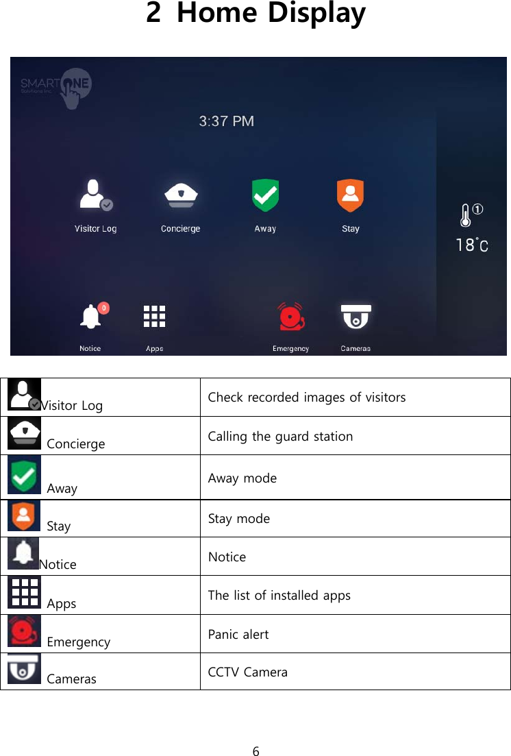
![8 4 Control 4.1. FCU Control FCU Control 1) Go to the [Indoor] tab. 2) If cold/heating is in operation, the activated image is displayed, and if it do not work, the disabled image is displayed. 3) You can turn on / off all cooling / heating machines by pressing the power button of "whole air conditioning / heating". 4) You can enable or disable all cold / heater exit mode by pushing "go out" button of "whole air conditioning / heating". 5) You can turn on / off the cooling / heating by pressing the power (1) button of the controlling cold / heater. 6) You can set temperature at one degree difference by pressing the button(②) . 7) The current temperature is displayed. [FCU Control]](https://usermanual.wiki/COMMAX/CIP-700MW/User-Guide-3674849-Page-8.png)
![9 FCU Away mode 1) Go to the [Indoor] tab 2) Press the ‘More’ button 3) Press the "ON" button in the go-out mode to set the go-out mode. Both the cold / heater will be turned off. 4) Pressing the "OFF" button in the go-out mode releases the go-out mode. The cold / heating machine will return to the status before going out. (When you turn on / off the power from away mode setting, you will be automatically unlocked.) Change the FCU mode 1) Press the "cooling" button to set the mode for cooling. 2) Press the "Heating" button, the mode is set for heating.](https://usermanual.wiki/COMMAX/CIP-700MW/User-Guide-3674849-Page-9.png)
![11 5.1. Intercom Guard Calling the security guard station [The screen of calling connection and calling screen] ① Active Call and Call Waiting ② Display of calling connection ③ Volume ④ Call Start ⑤ Call refusal, Cancel ⑥ Door Open ⑦ Save of Visitor image ※ ‘Call display’ can be displayed differently by each type of call from guard station and entrance ※ Some equipment does not provide CID function. ※ Visitors image can be saved in the storage space. Images can be stored by 128 cuts. (188MByte standards) ※ The file is same space for visitors image and CCTV Image. ※ Internet telephone cannot be used ① ② ③ ④ ⑤ ⑥ ⑦](https://usermanual.wiki/COMMAX/CIP-700MW/User-Guide-3674849-Page-11.png)
![14 5.2. Security Emergency operation Emergency in emergency situation Access control Access control 5.2.1. Emergency Emergency occurrence Emergency sensing An emergency occurs by the user or occurs automatically by the sensor Touch ‘Emergency’ button to send a notice of an emergency to Guard station. The emergency notice is processed in three steps such as ‘On’, ‘Off’, and ‘Reset’ Emergency on 1) Emergency can be generated by pressing the emergency icon or by pressing the emergency button on the front of the product. Or automatically by the sensor 2) Emergency type is displayed at the top of the screen with a siren sound [Emergency] Emergency stop 1) Touch ‘Stop’ button located at the bottom of Emergency screen. 2) Put the password (default password is ‘1234) and then press enter’.](https://usermanual.wiki/COMMAX/CIP-700MW/User-Guide-3674849-Page-14.png)
![15 [Password input]](https://usermanual.wiki/COMMAX/CIP-700MW/User-Guide-3674849-Page-15.png)
![16 5.3. Home History Visitor Log Viewing recorded images of visitors 5.3.1. Visitors Viewer Viewing recorded images of visitors from common entrance. [Viewing recorded images of visitors] Delete Delete selected images You can see where the picture was taken with the icon. My house Picture taken at my house Common entrance Images taken from an common entrance Out In case of go-out (Go out mode settings) Viewing recorded images In viewing a visitor mode, all recorded images from a common entrance can be checked including time and date information. You can also check visitors if you set out.](https://usermanual.wiki/COMMAX/CIP-700MW/User-Guide-3674849-Page-16.png)
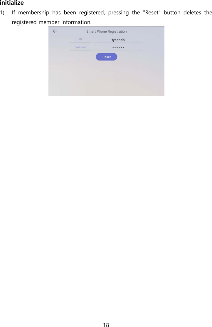
![17 Deleting recorded images 1) Touch ‘Delete’ button. 2) Select images or all the images by checking ‘Select all’ box. 3) Touch once more to uncheck the images or ‘Select all’ box. 4) Touch ‘Delete’ button to delete selected images. 5.4. ETC Settings Settings Sign Up User registration 5.4.1. Sign Up User registration/ Edit / Reset 1) Enter your ID and touch ‘ID check’ button to check for validity 2) Select your country 3) Enter your password and touch ‘Confirm’ button. [Sign Up]](https://usermanual.wiki/COMMAX/CIP-700MW/User-Guide-3674849-Page-17.png)
![19 6 Away/Stay Mode [Away mode] [Sraty mode]](https://usermanual.wiki/COMMAX/CIP-700MW/User-Guide-3674849-Page-19.png)
![20 6.1.1. Away Away Mode The status display of going out setting When you go out, you can set up these functions security sensor, visitor recording, light off, close gas valve, indirect call etc. Away mode setting 1) Press the icon, away mode will be started. 2) The away mode will be executed automatically after the specified away delay time. 3) If you want to cancel away mode, press ‘CANCEL’ button. [Go Out mode set-up] 1.Delayed time for go-out 3.Start away mode 2.Action item when going out ※ If security mode is on, away mode cannot be started. ※ Return home sensor delay setting is set by setting -> user option -> delayed from adjusted go out time. Set Go Out mode 1) Set items to be executed when go out mode 2) Press the ‘Option’ button on the setting screen of go out mode, the setting screen of go out mode is displayed. 3) Check the use security sensor and execution item to use. ② ③ ①](https://usermanual.wiki/COMMAX/CIP-700MW/User-Guide-3674849-Page-20.png)
![22 6.1.2. Burglar sensor settings burglar sensor settings on burglar sensor settings off ※ This function will be activated when the security devices have been installed. ※ You can set the using security sensors in ‘Setting>Connections COMMAX> Sensors’. Burglar sensor settings 1) Check the security sensor to be set by pressing the 'Areas (②)' button. 2) After settings, press ①(set) and the burglar sensor in adjusted area will be started. [Burglar sensor settings] ※ The number of burglar sensor settings images will be displayed as many as the number of adjusted sensors. Restore the burglar sensor 1) Press the 'Burglar sensor settings' button 2) Input the password and press the 'confirms' 3) If password is correct, the security mode will be restored ① ②](https://usermanual.wiki/COMMAX/CIP-700MW/User-Guide-3674849-Page-22.png)