Users Manual
1
Home Network User Manual
PMN: Wall PAD
2
Table of Contents
Introduction .................................................................................................................................................. 3
Part name ............................................................................................................................................. 3
Display composition ........................................................................................................................ 4
1 Screen Saver ...................................................................................................................................... 5
1.1. Information provided from the screen saver ........................................................ 5
2 Home Display .................................................................................................................................... 6
3 Notice ................................................................................................................................................... 7
4 Control ................................................................................................................................................. 8
4.1. FCU Control ......................................................................................................................... 8
5 Application ....................................................................................................................................... 10
5.1. Intercom .............................................................................................................................. 11
5.2. Security ................................................................................................................................ 14
5.3. Home History ................................................................................................................... 16
5.4. ETC ......................................................................................................................................... 17
6 Away/Stay Mode ............................................................................................................................ 19
7 Appendix ........................................................................................................................................... 23
7.1. Using the Owner mobile app .................................................................................... 23
7.2. Using the Guest mobile app ...................................................................................... 27
7.3. Etc .......................................................................................................................................... 30
7.4. Name Search(LOBBY PHONE) .....오류! 책갈피가 정의되어 있지 않습니다.
3
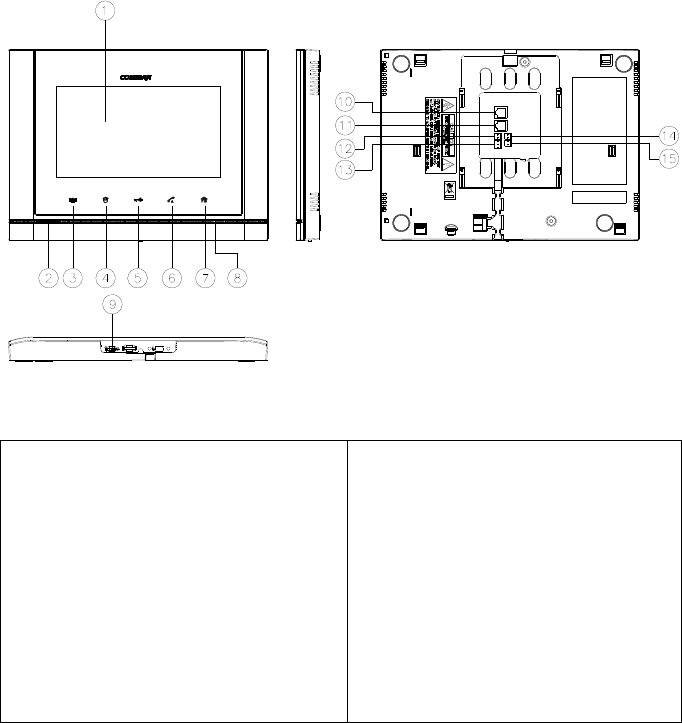
Introduction
Part name
① TFT LCD
② Speaker
③ Emergency button
④ Call guard station
⑤ Door release button
⑥ Call button
⑦ Home Button
⑧ Microphone
⑨ Power Switch
⑩ PoE
⑪ PIR
1. Sensor_in, 2. GND, 3. VCC
⑫ EM
⑬ RS-485
1. TRX-, 2. TRX+, 3.GND
⑭ DDL VCC (OPTION)
⑮ DDL S/W (OPTION)
4
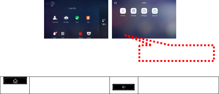
Display composition
Buttons at the Bottom
Go to Home Back
Press the button
5
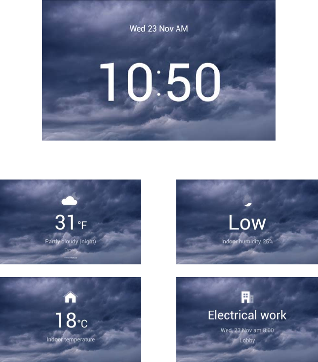
1 Screen Saver
We will provide information on the screen sequentially
Press the screen saver to go to the home screen.
1.1. Information provided from the screen saver
[Today's weather information] [Indoor humidity]
[Indoor temperature] [Notice]
※ It is not provided when there is no information.
※ Weather information should be connected to the external Internet to the server.
6
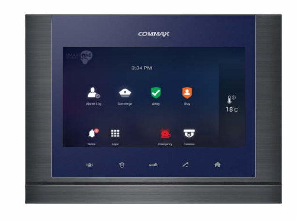
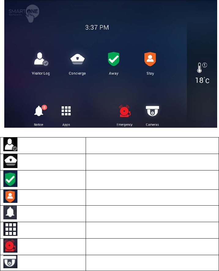
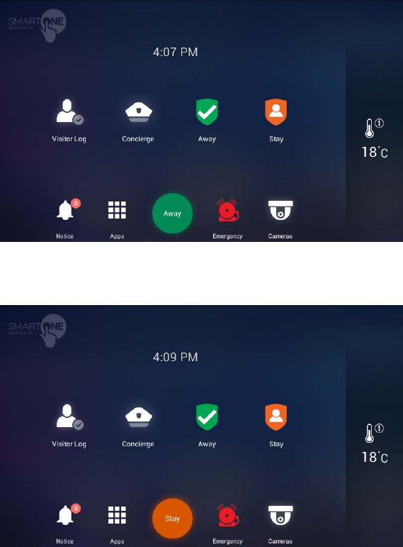
2 Home Display
Visitor Log Check recorded images of visitors
Concierge Calling the guard station
Away Away mode
Stay Stay mode
Notice Notice
Apps The list of installed apps
Emergency Panic alert
Cameras CCTV Camera
7
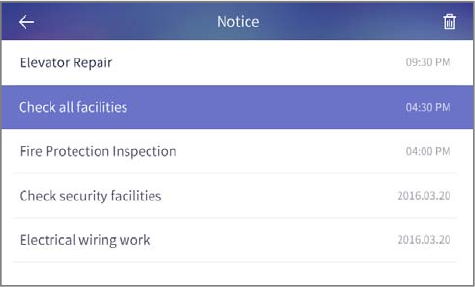
3 Notice
You can check the notices
[Notices]
8
4 Control
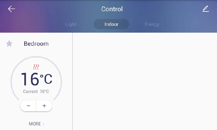
4.1. FCU Control
FCU Control
1) Go to the [Indoor] tab.
2) If cold/heating is in operation, the activated image is displayed, and if it
do not work, the disabled image is displayed.
3) You can turn on / off all cooling / heating machines by pressing the power
button of "whole air conditioning / heating".
4) You can enable or disable all cold / heater exit mode by pushing "go out"
button of "whole air conditioning / heating".
5) You can turn on / off the cooling / heating by pressing the power (1)
button of the controlling cold / heater.
6) You can set temperature at one degree difference by pressing the
button(②) .
7) The current temperature is displayed.
[FCU Control]
9
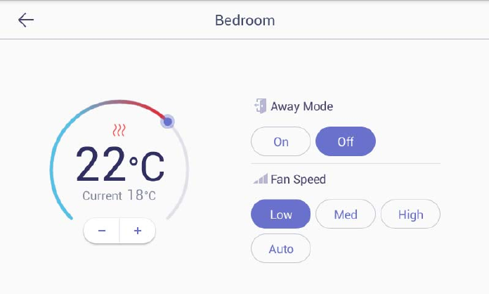
FCU Away mode
1) Go to the [Indoor] tab
2) Press the ‘More’ button
3) Press the "ON" button in the go-out mode to set the go-out mode. Both
the cold / heater will be turned off.
4) Pressing the "OFF" button in the go-out mode releases the go-out mode.
The cold / heating machine will return to the status before going out.
(When you turn on / off the power from away mode setting, you will be
automatically unlocked.)
Change the FCU mode
1) Press the "cooling" button to set the mode for cooling.
2) Press the "Heating" button, the mode is set for heating.
10
5 Application
11
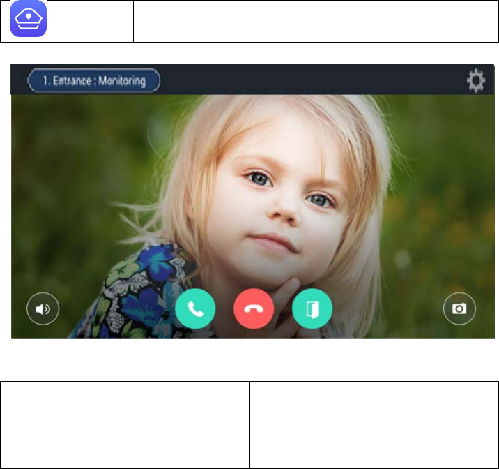
5.1. Intercom
Guard Calling the security guard station
[The screen of calling connection and calling screen]
① Active Call and Call Waiting
② Display of calling connection
③ Volume
④ Call Start
⑤ Call refusal, Cancel
⑥ Door Open
⑦ Save of Visitor image
※ ‘Call display’ can be displayed differently by each type of call from guard station
and entrance
※ Some equipment does not provide CID function.
※ Visitors image can be saved in the storage space.
Images can be stored by 128 cuts. (188MByte standards)
※ The file is same space for visitors image and CCTV Image.
※ Internet telephone cannot be used
① ②
③ ④ ⑤ ⑥ ⑦

12
5.1.1. Common entrance
Open the door for common entrance
1) During the called of individual and common entrance please press
(Door Open) the button.
Recording visitor’s image from common entrance
1) Press ‘Capture an image’ button while paging or calling.
2) If successfully recorded, the visitor's photos which are confirmed visitors
on the home screen will be displayed.
Pick up the phone from Common Entrance
1) The visitor will be displayed on the screen with bell sounds
2) If pick up the phone please press button or please reject button.
3) If hang up the phone please press the button.

13
5.1.2. Guard station
Calling a guard station
Calling a guard station
1) To call a guard station, touch ‘Guard station’ icon or touch ‘Guard station’
button in dialing mode
2) To hang up a call, touch ‘End call’ button.
Receiving a call from a guard station
1) When the call is received from a guard station, the touch panel rings and
displays a guard station icon on the screen.
2) To receive a call, touch (Call) button. To reject a call, touch ‘Cancel’
button.
3) To hang up a call, touch ‘End call’ button.
※ Security office and management office cannot see the user’s image.
※ The guard video call is only available for products with video call cameras
※ If you use the call transfer function during the guard station call, the guard
station call is automatically terminated
※ Setting of security office -> Connect to COMMAX and control -> setting to
number -> Security and management office can be settled.
Call switching function
1) If someone calls you during a calling, it will be displayed on the screen.
2) Touch (Switch call) button to answer the call. The previous call is
disconnected as you switch the call
※ Some devices do not provide CID functionality (Caller ID).
※ Call transfer is not supported on some calls
14
5.2. Security
Emergency operation Emergency in emergency situation
Access control Access control
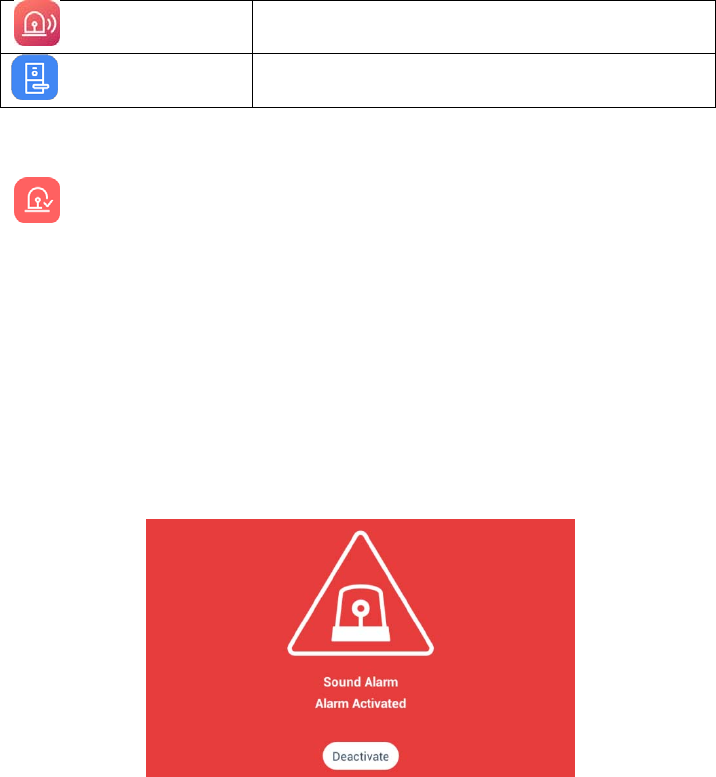
5.2.1. Emergency
Emergency occurrence
Emergency sensing
An emergency occurs by the user or occurs automatically by the sensor
Touch ‘Emergency’ button to send a notice of an emergency to Guard station. The
emergency notice is processed in three steps such as ‘On’, ‘Off’, and ‘Reset’
Emergency on
1) Emergency can be generated by pressing the emergency icon or by
pressing the emergency button on the front of the product. Or
automatically by the sensor
2) Emergency type is displayed at the top of the screen with a siren sound
[Emergency]
Emergency stop
1) Touch ‘Stop’ button located at the bottom of Emergency screen.
2) Put the password (default password is ‘1234) and then press enter’.
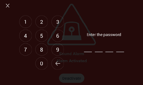
15
[Password input]
16
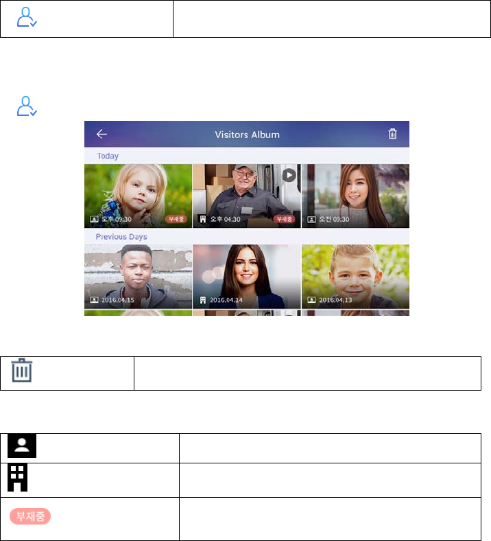
5.3. Home History
Visitor Log Viewing recorded images of visitors
5.3.1. Visitors Viewer
Viewing recorded images of visitors from common entrance.
[Viewing recorded images of visitors]
Delete Delete selected images
You can see where the picture was taken with the icon.
My house Picture taken at my house
Common entrance Images taken from an common entrance
Out In case of go-out
(Go out mode settings)
Viewing recorded images
In viewing a visitor mode, all recorded images from a common entrance can be
checked including time and date information. You can also check visitors if you set
out.
17
Deleting recorded images
1) Touch ‘Delete’ button.
2) Select images or all the images by checking ‘Select all’ box.
3) Touch once more to uncheck the images or ‘Select all’ box.
4) Touch ‘Delete’ button to delete selected images.
5.4. ETC
Settings Settings
Sign Up User registration
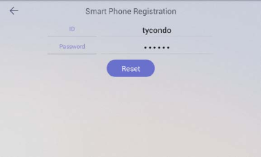
5.4.1. Sign Up
User registration/ Edit / Reset
1) Enter your ID and touch ‘ID check’ button to check for validity
2) Select your country
3) Enter your password and touch ‘Confirm’ button.
[Sign Up]
18
initialize
1) If membership has been registered, pressing the "Reset" button deletes the
registered member information.
19
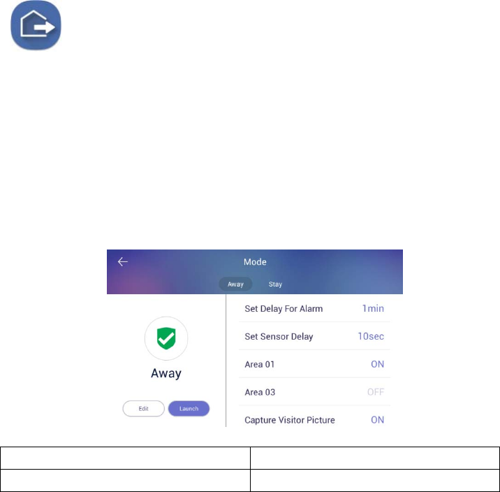
6 Away/Stay Mode
[Away mode]
[Sraty mode]
20
6.1.1. Away
Away Mode
The status display of going out setting
When you go out, you can set up these functions security sensor, visitor recording,
light off, close gas valve, indirect call etc.
Away mode setting
1) Press the icon, away mode will be started.
2) The away mode will be executed automatically after the specified away
delay time.
3) If you want to cancel away mode, press ‘CANCEL’ button.
[Go Out mode set-up]
1.Delayed time for go-out 3.Start away mode
2.Action item when going out
※ If security mode is on, away mode cannot be started.
※ Return home sensor delay setting is set by setting -> user option -> delayed
from adjusted go out time.
Set Go Out mode
1) Set items to be executed when go out mode
2) Press the ‘Option’ button on the setting screen of go out mode, the
setting screen of go out mode is displayed.
3) Check the use security sensor and execution item to use.
②
③
①
21
4) Press ‘confirm’ button to save.
Restore Go Out mode
1) Press “Go Out mode“ button
2) When it appears on the password input screen, enter the password and
click the 'confirm' button.
3) If the passwords match, go out mode will be canceled.
22
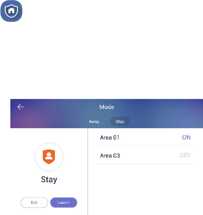
6.1.2. Burglar sensor settings
burglar sensor settings on
burglar sensor settings off
※ This function will be activated when the security devices have been installed.
※ You can set the using security sensors in ‘Setting>Connections COMMAX>
Sensors’.
Burglar sensor settings
1) Check the security sensor to be set by pressing the 'Areas (②)' button.
2) After settings, press ①(set) and the burglar sensor in adjusted area will be
started.
[Burglar sensor settings]
※ The number of burglar sensor settings images will be displayed as many as the
number of adjusted sensors.
Restore the burglar sensor
1) Press the 'Burglar sensor settings' button
2) Input the password and press the 'confirms'
3) If password is correct, the security mode will be restored
① ②
23
7 Appendix
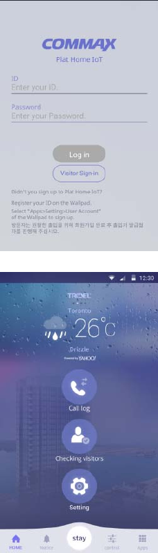
7.1. Using the Owner mobile app
Login
1) Enter the ID and password that you registered
to in the Wallpad
2) Press the "Login" button.
3) Enter your nickname and Press the 'OK' button.
4) In the home screen, you can select "Call Log",
"Checking visitors", and "Setting".
24
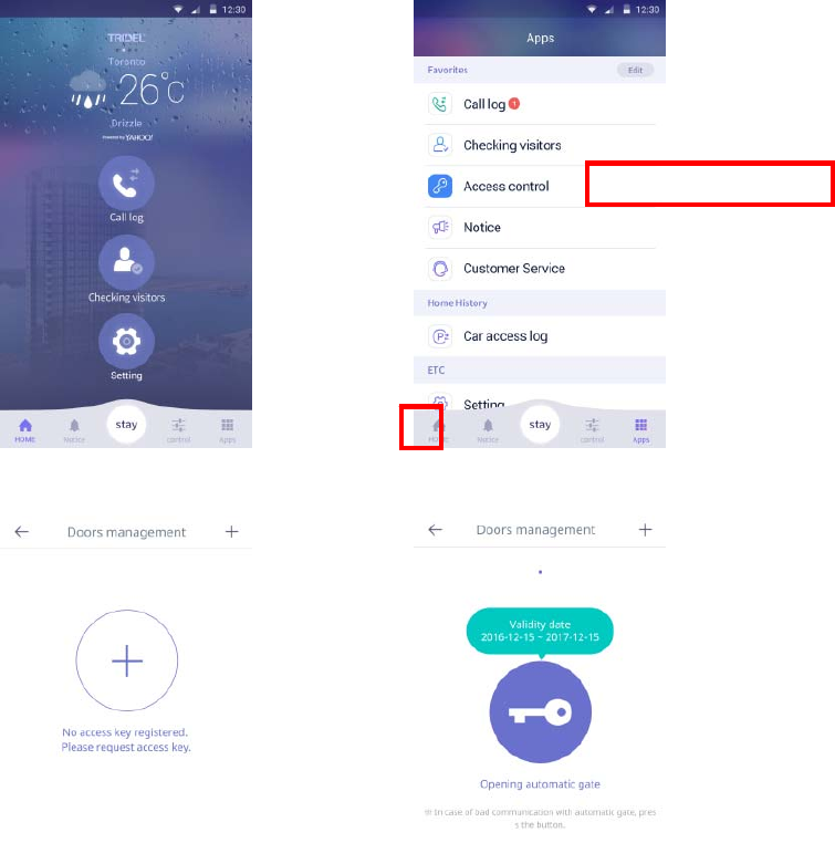
Issuing Access Keys
1) Press the 'Apps' button on the
home screen.
2) Press the ‘Access Control’ button.
3) Press the ‘Doors management’ button.
4) Press the "+" button and the
access key will be issued.
5) “①”If there is more than one key that
has been issued, you can move it by
checking the left / right page.
6) “②”The expiration date of the access
key is displayed.
7) “③”If not recognized automatically,
press the "Open door" button to open
the door.
①
②
③
25
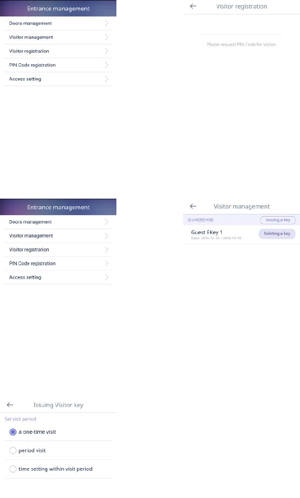
Guest Visit Key Issued
1) Press the ‘Visitor registration’
button.
2) Press the ‘Request’ button.
3) The issued authentication key will
be notified by phone or SMS to the
guest within 3 minutes.
4) When the validity time has elapsed,
the authentication key is reissued.
5) Press the ‘Visitor management’
button.
6) After the guest registers, if you
enter the authentication key, Guest
is displayed in ‘Visitor
management’.
7) Press the ‘Issuing a key’ button
8) You can set the visitor's visit time.
- One-time visit
- Period visit
- Time setting within a period
26
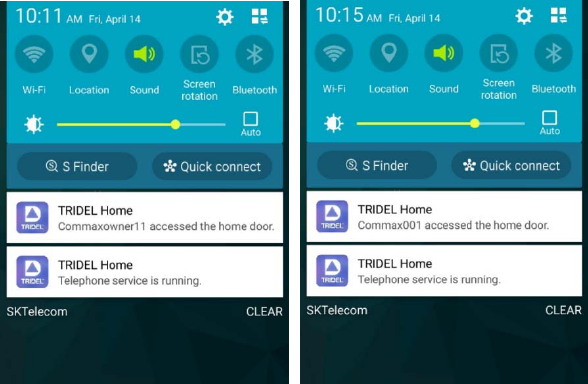
The visitor access notice message
When an owner and guests visit, a push message is provided on the mobile.
Notification push messages is displayed as nickname entered you signed up.
27
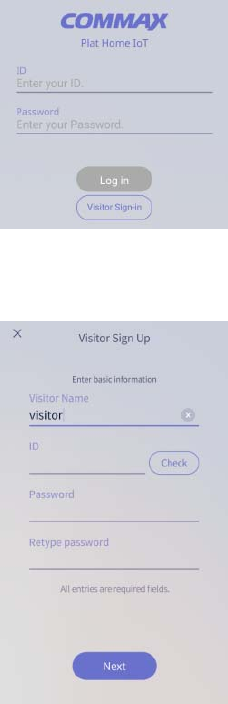
7.2. Using the Guest mobile app
Login
1) Press the ‘Visitor Sign-in’ button.
2) Enter ‘Visitor Name’, ‘ID’, ‘Password’, ‘Retype
password’.
3) Press the ‘Next’ button.
4) Press the ‘Login’ button when the registration is
completed.
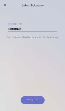
28
5) Enter the nickname to use and Press the
‘Confirm’ button.
29
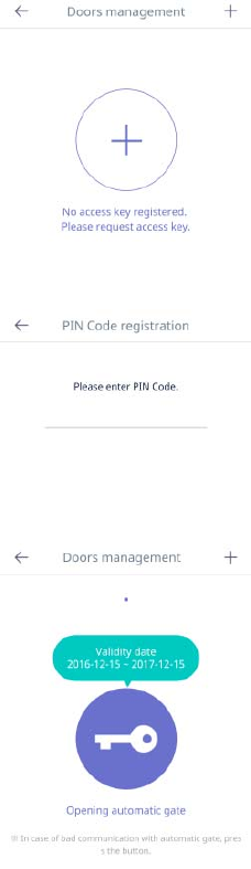
Request a visit key
1) Press the "+" button to request a visit key.
2) Enter the authentication key received from the
owner.
3) When the owner confirms and releases the
access key, the access key is displayed.
4) “①”The expiration date of the access key is
displayed.
5) “②”If not recognized automatically, press the
"Open door" button to open the door.
①
②
30
7.3. Etc
Door Open
1) Touch the keypad on the door lock (DDL).
2) If the "Auto Setup" is set, the door automatically
opens.
3) If "Auto Access" has not been set, you can press the
"Door open" button on the Mobile Appliance to enter
or exit.
Door lock(DDL) setting
Setting Manual Lock
1) Touch the keypad of the door lock (DDL).
2) Enter the password for the door lock. (Ex)) password:
2580)
3) Enter #+#+7.
(Ex: 2580##7)
Setting Auto Lock
1) Touch the keypad of the door lock (DDL).
2) Enter the password for the door lock. (Ex)) password:
2580)
3) Enter #+#+4.
(Ex: 2580##4)
※ If you set the door lock (DDL) manually, you must touch the keypad to
lock the door when closing the door lock
31
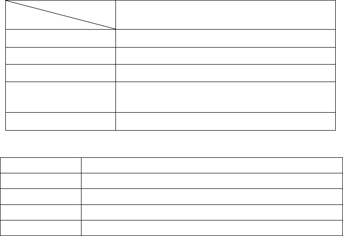
PRODUCT
MODLE
SPEC CIP-700MW
LINE UTP (CAT.5e)
VOLTAGE INPUT : PoE DC 48V
TELECOMUNNICATION AUDIO : VoIP, VIDEO : H.264
LINE & DISTANCE STANDARD UTP (CAT.5e) 70m
(FROM THE PSE)
TEMPERATURE 0℃ ∼ +40℃
SPECIFICATION
CPU Dual-Core ARM Cortex-A7
MEMORY 1G DDR3 RAM (512M *2)
FLASH 4G eMMC Flash
LCD 7” TFT LCD, 800 x 480
POWER PoE
32
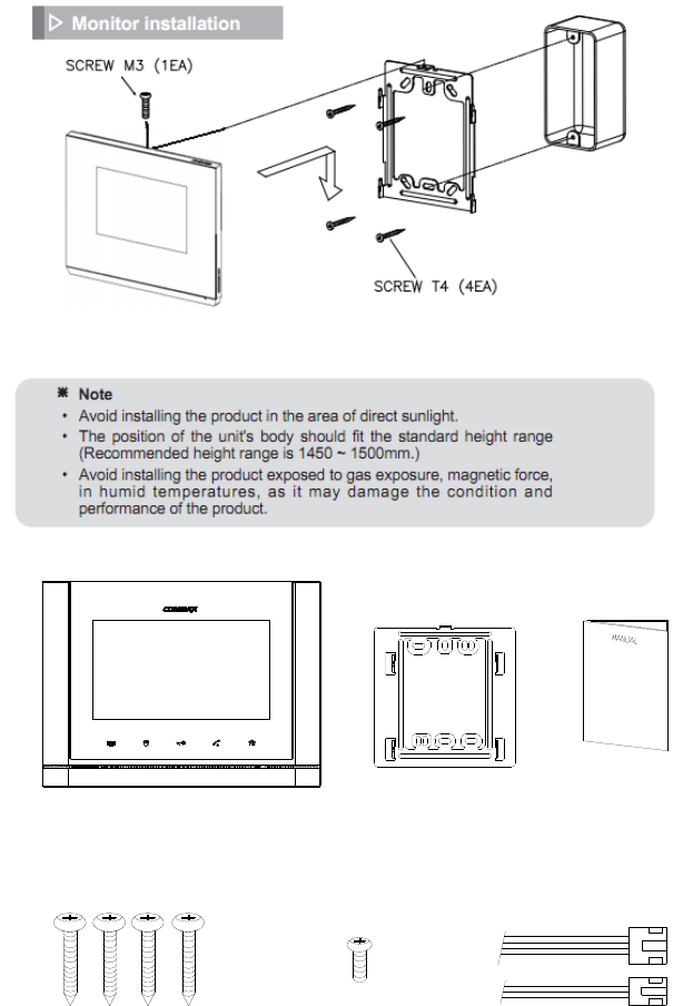
INSTALLATION
PACKAGE CONTENTS.
MONITOR FIXING
WALL BRACKET
WALL BRACKET
MONITOR (CIP-700MW)
CONNECTOR
MANUAL
3P(1EA)/2P(1EA)
(M) 3 x 6mm(T) 4 x 18mm
MOUNTING SCREW(4EA) SCREW(1EA)

33
FCC Compliance Statement
This device complies with part 15 of the FCC rules.
Operation is subject to the following two conditions:
(1) This device may not cause harmful interference, and
(2) This device must accept any interference received, including interference that
may cause undesired operation.
This equipment has been tested and found to comply with the limits for a Class B
digital device pursuant to part 15 of the FCC rules. These limits are designed to
provide reasonable protection against harmful interference in a residential
installation. This equipment generates, uses and can radiate radio frequency energy
and, if not installed and used in accordance with the instructions, may cause
harmful interference to radio communications. However, there is no guarantee that
interference will not occur in a particular installation. If this equipment does cause
harmful interference to radio or television reception, which can be determined by
turning the equipment on and off, the user is encouraged to try to correct the
interference by one or more of the following measures:
• Reorient or relocate the receiving antennae
• Increase the separation between the equipment and the receiver
• Connect the equipment into an outlet on a circuit different from that to which the
receiver is connected.
• Consult the dealer or an experienced radio/TV technician for help.
FCC Caution
Any changes or modifications to the equipment not expressly approved by the
party responsible for compliance could void user’s authority to operate the
equipment.

34
This equipment should be installed and operated with minimum 20 cm between the
radiator and your body.
Cet équipement doit être installé et utilisé avec un minimum de 20 cm entre le
radiateur et votre corps.
Industry Canada Statement
This device complies with Industry Canada license-exempt RSS standard(s).
Operation is subject to the following two conditions:
(1) This device may not cause interference.
(2) This device must accept any interference, including interference that may cause
undesired operation of the device.
Déclaration de conformité IC (Industrie Canada)
Le présent appareil est conforme aux CNR d'Industrie Canada applicables aux appareils radio
exempts de licence. L'exploitation est autorisée aux deux conditions suivantes :
(1) Cet appareil ne doit pas créer d'interférences.
(2) Cet appareil doit accepter toutes les interférences reçues, y compris celles qui pourraient
entraver son bon fonctionnement.