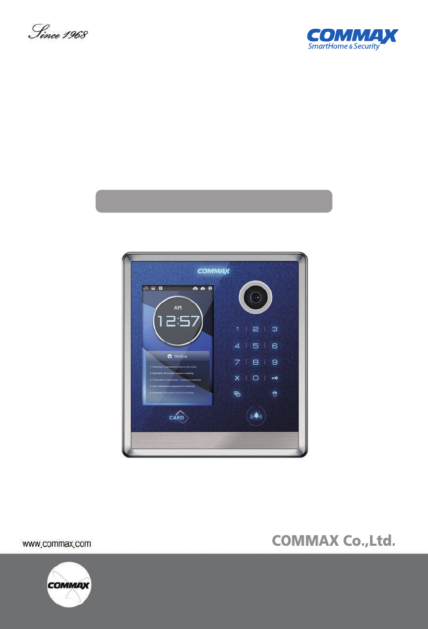
User Manual
•Thank you for purchasing COMMAX products.
•Please carefully read this User’s Guide (in particular, precautions for safety) before using a product and follow
instructions to use a product exactly.
•The company is not responsible for any safety accidents caused by abnormal operation of the product.
513-11, Sangdaewon-dong, Jungwon-gu, Seongnam-si, Gyeonggi-do, Korea
Int’l Business Dept. Tel. : +82-31-7393-540~550 Fax. : +82-31-745-2133
Web site : www.commax.com
•Thank you for purchasing COMMAX products.
•Please carefully read this User’s Guide (in particular, precautions for safety) before using a product and follow
instructions to use a product exactly.
•The company is not responsible for any safety accidents caused by abnormal operation of the product.
COMMAX LOBBY PHONE DRC-703S
User Manual

1
●Thank you for choosing COMMAX.
●Please read this manual carefully before you use the product.
Greetings ..................................................................................................................1
Contents table...........................................................................................................1
1. Warnings and caution ...........................................................................................2
2. Part names............................................................................................................4
3. Main Screen Setting..............................................................................................5
4. Security Call..........................................................................................................6
5. Call house.............................................................................................................7
6. Access authorization.............................................................................................9
7. Set up..................................................................................................................11
8. Wiring Diagram ...................................................................................................15
Greetings
Table of contents
2
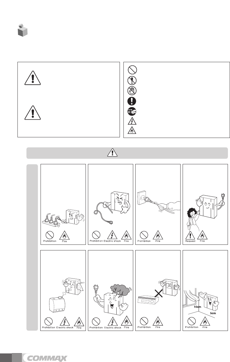
1. Warnings and caution
Please follow the things described below in order to prevent any
danger or property damage.
Warning
Caution
Prohibition.
No disassembly
No touch
Must follow strictly.
Shows plugging out the power cord
without an exception
Shows the warning and caution for an electric shock.
Shows the warning and caution for a fire.
It may cause a serious damage or
injury if violated.
It may cause a minor damage or
injury if violated.
Power & Installation
Warning
Please don’t use several
products at the same time on
one power socket.
·It may cause a fire due to an
abnormal overheating.
Please don’tbend the power
cable excessively or it may
cause an electric shock.
·fire when using a damaged
power cable.
Please don’t handle the power
cable with a wet hand.
·It may cause an electric
shock.
Please plug out the power
cable from the socket when
not using it for a long period
of time.
·It may shorten the product
lifespan or cause a fire.
Please don’t install the
product in the place where
there is much oil, smoke or
humidity.
·It may cause an electric
shock or fire.
Please don’t install the
product with the lightening
and thunder.
·It may cause an electric
shock or fire.
Please don’tuse and connect
this product with other
products with different rated
voltage
·It may cause a disorder or
fire.
When installing the product
that generates heat, please
install the product away from
the wall (10cm) for the
ventilation.
·It may cause a fire due to
the increased internal
temperature.
3
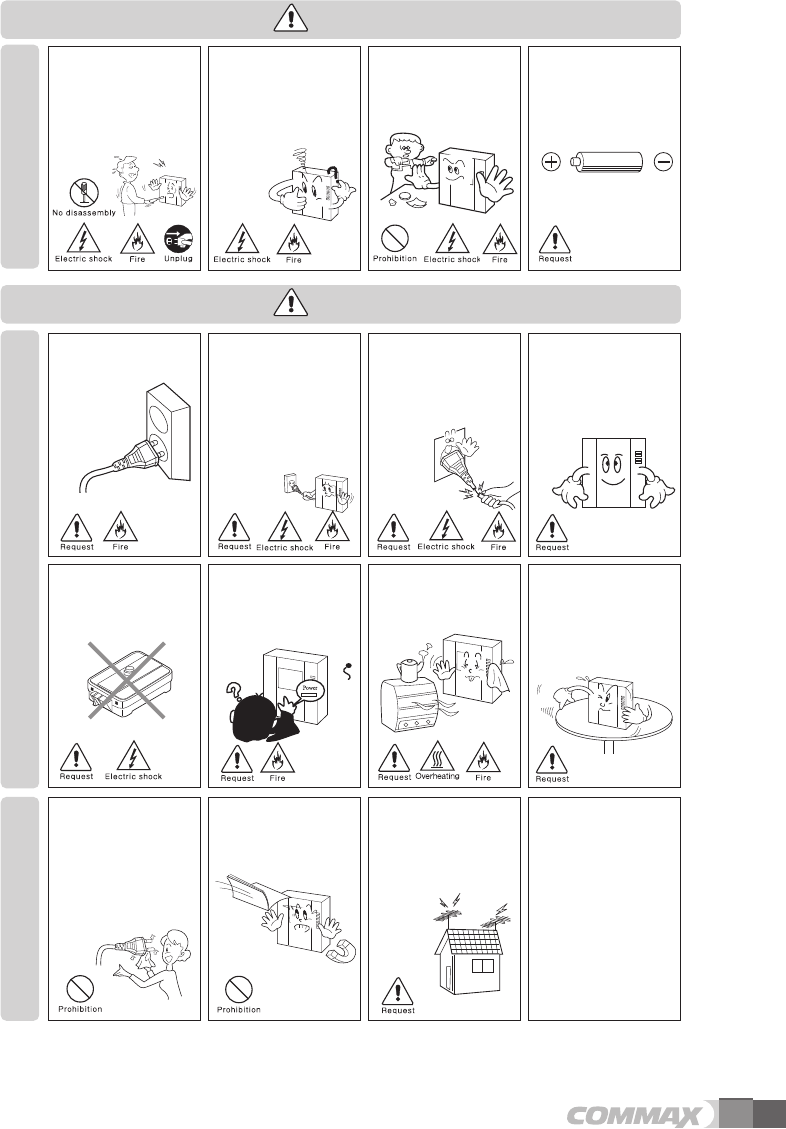
Cleaning & Use
Please don’tdisassemble,
repair or rebuild this product
arbitrarily (please contact the
service center if a repair is
needed.
·It may cause an electric
shock or fire.
Please plug the power cable
firmly into the inner end
·It may cause a fire.
Please hold the plug tightly
when unplugging the power
cable (a part of the copper
wire may be disconnected if
the grabbing is only made on
the cord when pulling out the
cable).
·It may cause an electric
shock or fire
When connecting the power
cables after cutting the cable,
please install the product with
power off
·It may cause an electric
shock or fire
When installing the product,
please fix it firmly while using
the wall-mounting unit and
screws.
·It may cause an injury from
the falling object.
Please be careful when using
an AC circuit breaker since
there is a possibility of an
electric shock.
When cleaning the product,
please rub it with a soft and
dry cloth after plugging out
the power cable. (Please don’t
use any chemical products
such as wax, benzene, alcohol
or cleanser.)
Please don’t drop the product
on the ground and don’tapply
a shock .
·It may cause a failure.
Please use the designated
connection cable within the
maximum calling distance
designated for the product
·It may reduce the product
performance.
Please check the use voltage
and current for the DC-only
products and use the
appropriate rectifier.
·It may cause a fire.
Please avoid direct rays of the
sun or heating devices at a
time of installation.
·It may cause a fire.
Please don’t install the
product on an unstable place
or small support board.
·It may cause an injury if it
falls down while in use.
If an abnormal sound, burning
smell or smoke is coming out
of the product, please plug out
the power cable and contact a
service center.
·It may cause an electric
shock or fire.
Please don’t insert any
metallic or burnable materials
into the ventilation hole.
·It may cause an electric
shock or fire.
Please use only the designated
batteries for the products of
using DC power.
·It may cause an electric
shock or fire.
Cleaning & UsePower & Installation
Warning
Caution
4
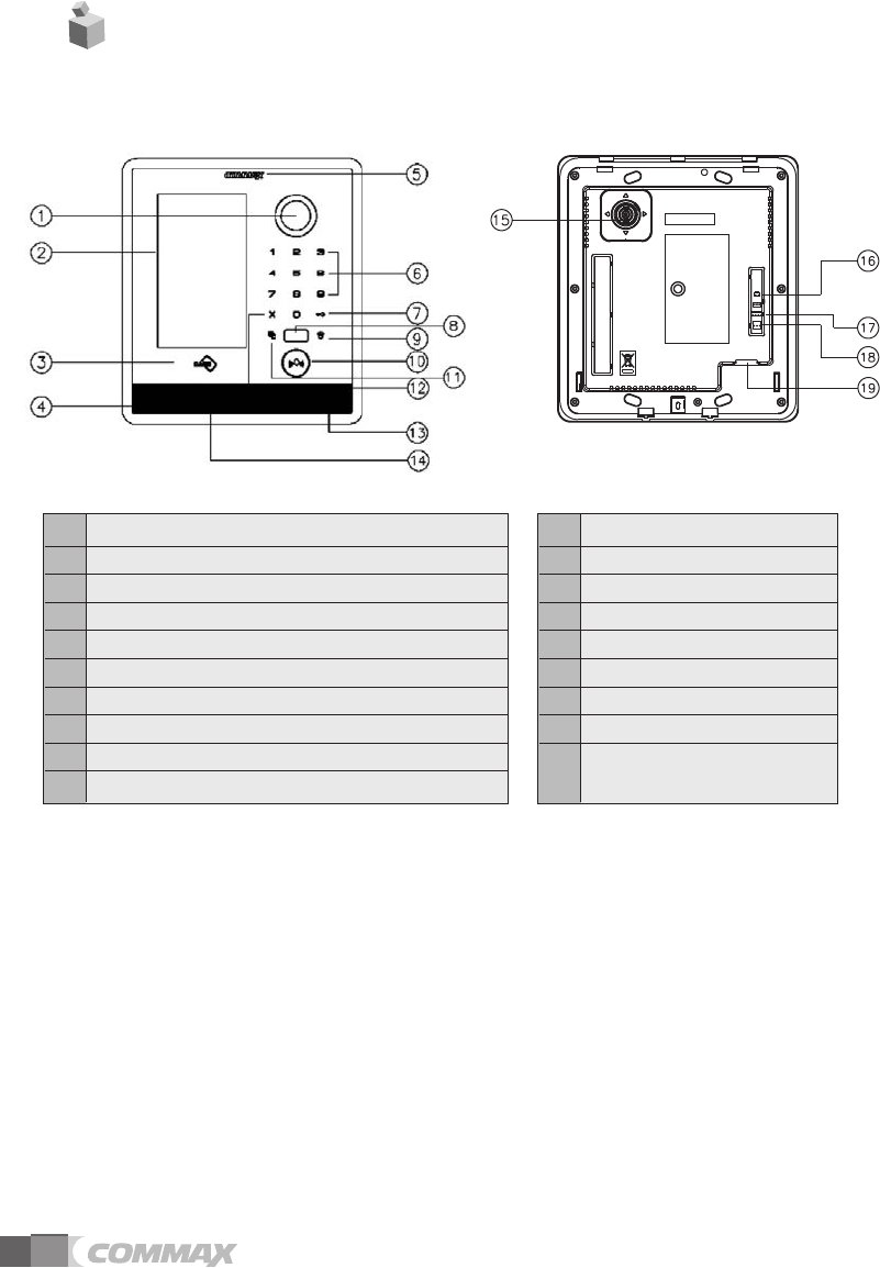
2. Part names
①Camera
②LCD
③RF CARD Receiver
④Mike
⑤LED
⑥Number Key Button
⑦Electric Key Button(in case of input the password)
⑧Proximity IR Sensor
⑨Security Button
⑩Call Button
⑪Program Button
⑫Cancel Button
⑬Speaker
⑭Reset
⑮Camera Adjustment Part
⑯DC 14V
⑰RS-485/Zigbee
⑱Switch Connection (NO,NC)
⑲LAN PORT
5
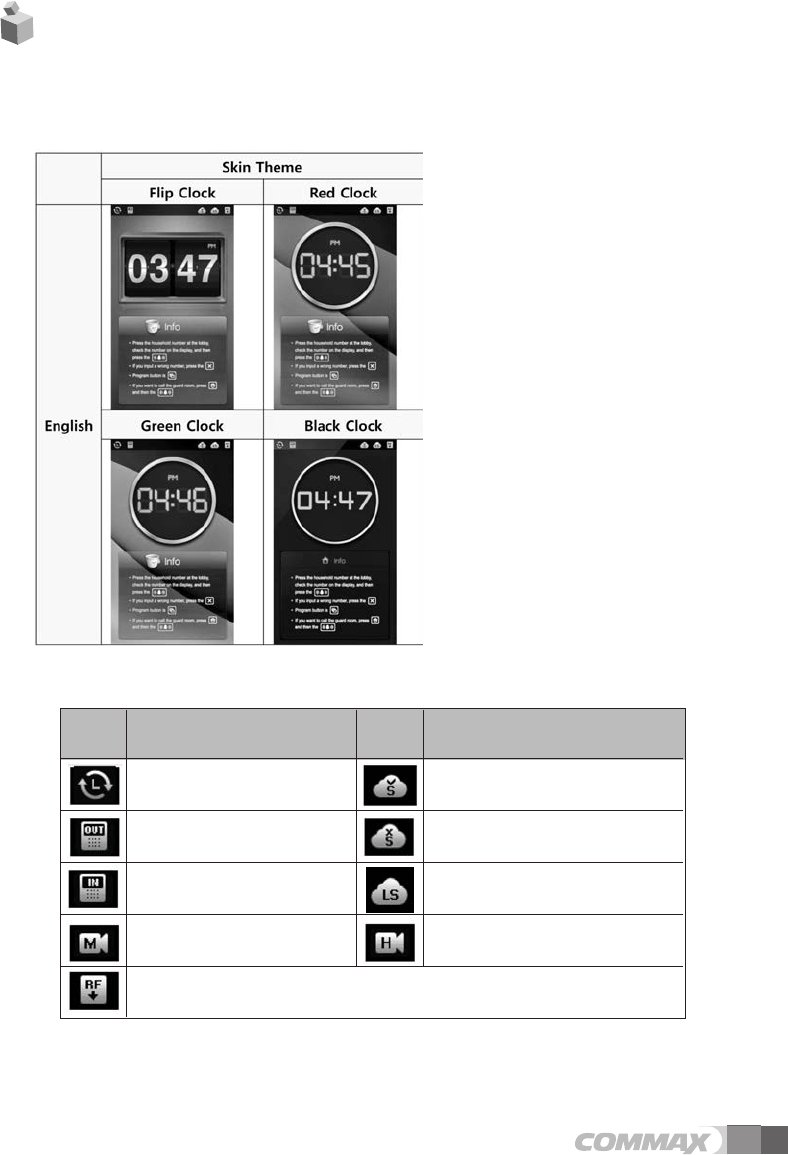
●Main Screen
3. Main Screen Setting
●Status
Icon Description Icon Description
Lan Connection Registered server status
Display out post lobby phone Not Registered server status
Display building lobby phone Local Server connection status
Display Video Codec(MPEG-4)
Display Video Codec(H.264)
RF Card Data save status
6
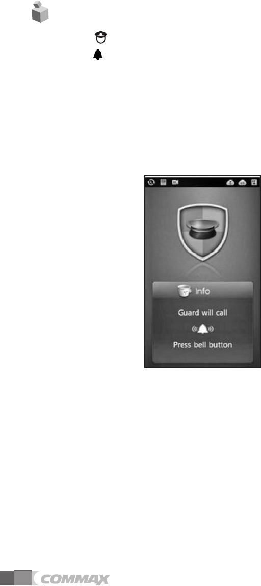
①Push (Security Guard Post) Button
②Push (Call) button
③Call sound is ringing and call Security Guard Post.
④Call Security Guard Post when guard answer call. (Time: 1 min.)
⑤Press "X" button when terminate call.
⑥Security Guard push 'Open door’ button, 'Door is open” voice comment then door is
open.
⑦If line is busy, call it later.
This is to call up the registered guard stations in advance by a manager
Picture1. Call security Guard
4. Security Call
7
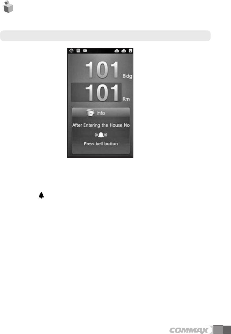
When building number is set in advance : When building No. already registered to Call Prefix
①Input unit No. to key board.
Ex) Unit 101 input ‘101’
②Push (call) button.
③Ringing call sound and call unit.
④When tenants answer call, calling is on. (Max. time: 1 min)
⑤Press "X" button when terminate call.
⑥Tenant push 'Open door’ button, "Door is open” voice comment then door is open
Picture2. Screen for registering house No.
5. Call house
●Communication call between residence
8
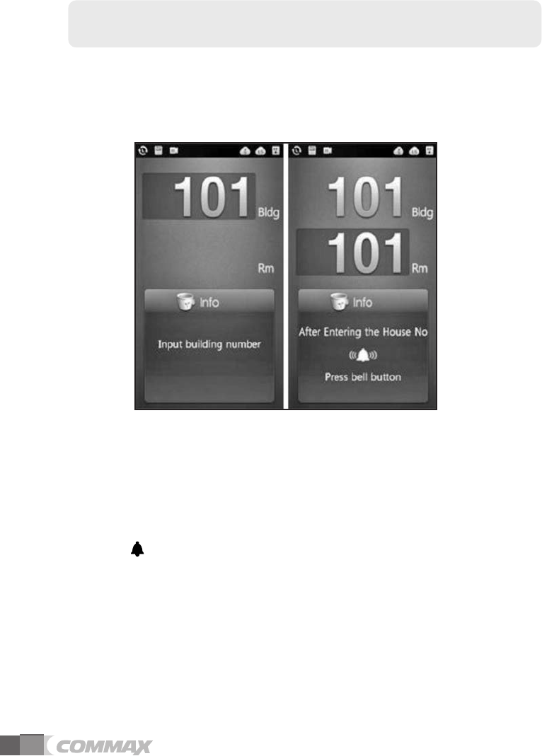
When building number is NOT set in advance :
When building number hasn't been registered Call Prefix yet.
①Input Building No. to key board.
Ex) Building 101 input ‘101’
②Input unit No. to key board.
Ex) Unit 101 input ‘101’
③Push (call) button.
④Ringing call sound and call unit.
⑤When tenants answer call, calling is on. (Max. time: 1 min)
⑥Press "X" button when terminate call.
⑦Tenant push 'Open door’ button, "Door is open” voice comment then door is open
Picture3. Building house No. register screen
9
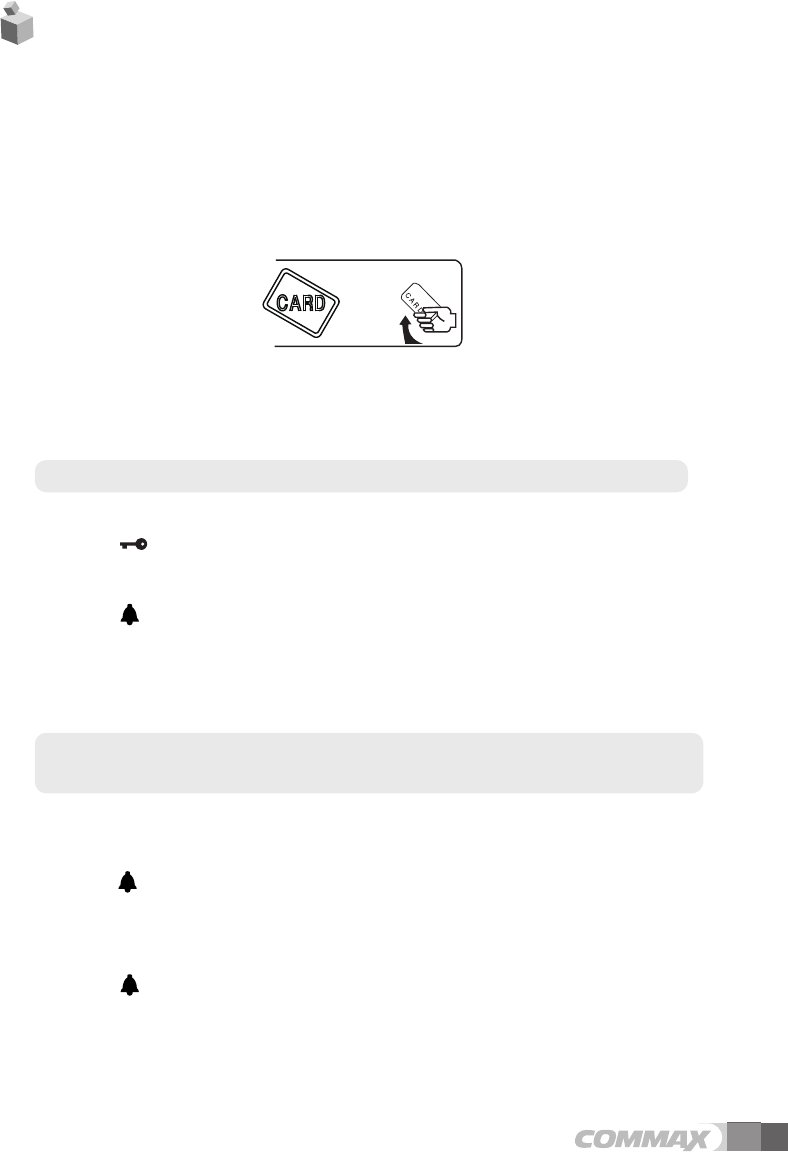
Picture4. Tag RF-Card
●
●Opening the entrance with RF card.
①Tag RF card to 'Card tagging window’.
②The common entrance get be opened with a vocal message, "Door opens” when
the access is successful.
③The entrance does not be opened when the access fails with sound.
●
●Access by PIN No.
Building Number designated case : Building Number designated in Call Prefix
①Input unit No. through key board.
②Push (Key) button.
③Input designated house PIN No.
④Push (call) button.
⑤If access authorization is successful, Door is open with "Door is open” voice message.
⑥If access is failed, warning sound is activated.
Building Number is not designated case :
Building Number is not designated in Call Prefix
①Input Building No. through key board.
EX) Building 101 Input 101
②Push (call) button.
③Input unit No. through key board.
Ex) Unit 101 Input 101
④Push (call) button.
⑤If access authorization is successful, Door is open with "Door is open” voice message.
⑥If access is failed, warning sound is activated.
6. Access authorization
외출/방범 버튼/LED홈버튼
외출/방범 버튼/LED홈버튼
외출/방범 버튼/LED홈버튼
외출/방범 버튼/LED홈버튼
10
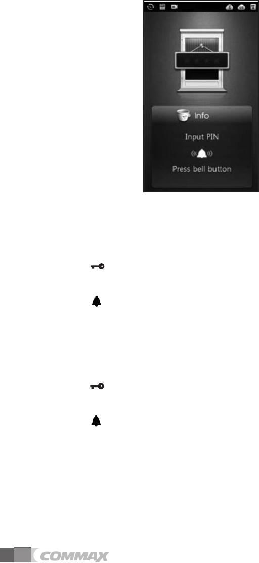
Picture5. Input password (PIN)
●
●Use password for accessing when system is OFF-Line
(No connection with Local server)
①Push (Key) button.
②Input PIN number.
③Push (call) button.
Please, should delete OFF-LINE PIN number when On-Line mode is activated
●
●Use password for accessing when system is ON-Line
(When connected with Local server)
①Push (Key) button.
②Input Administration Pin number
③Push (call) button.
외출/방범 버튼/LED홈버튼
외출/방범 버튼/LED홈버튼
외출/방범 버튼/LED홈버튼
외출/방범 버튼/LED홈버튼
11
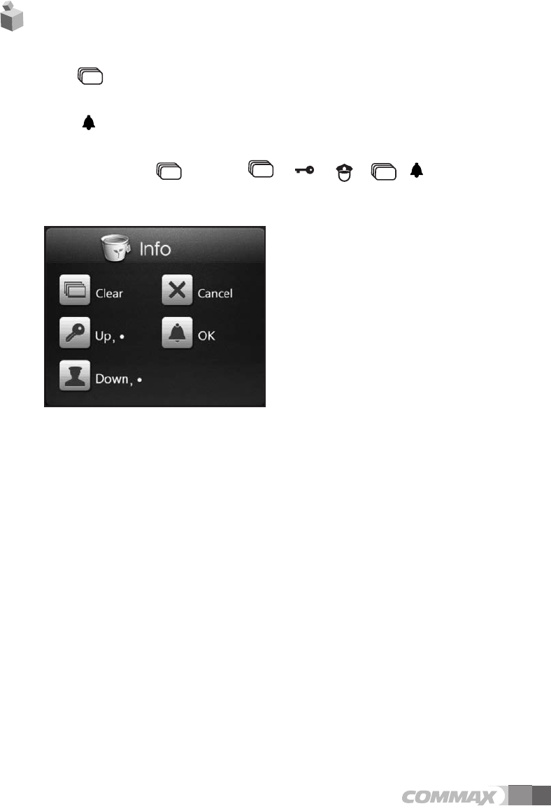
●Set up
1. Push button.
2. Input PIN number.
3. Push (call) button.
We recommend user change initial password (0000) then use products for security.
Initialize password : + “0000”+ + + + +
●
●Set up menu
0 : Set Network+
0 : IP address: (Input IP address)
1 : G/W address (Input Gateway address)
2 : DNS address (Input DNS address)
3 : Net mask (Input network mask)
1 : Set VoIP+
0 : SIP Server (Input SIP server address)
1 : Guard ID (Input Security Guard Post)
“●”is DOT (.) for IP address typing.
●button map
7. Set up
외출/방범 버튼/LED홈버튼
외출/방범 버튼/LED홈버튼
외출/방범 버튼/LED홈버튼
0
123
456
789
0
123
456
789
외출/방범 버튼/LED홈버튼
0
123
456
789
0
123
456
789
2 : Management+
0 : Server address (Input Local server address)
1 : Update address (Input update server address)
2 : System ID (Input DRC-700S serial No.)
3 : Call Prefix (Set building)
If there is no building information in set up, automatically pop up for building
information when call house.
4 : Call Line+
0 : Min Call Line (Input call Min. line)
1 : Max Call Line (Input call Max. line)
Attention : If Min Call Line is bigger than Max Call Line, you can’t call it.
5: Position (Set DRC-703S location)
button is for upper ground, button is for underground.
Ex) When user set first floor after pushing button, “1” is displayed and
pushing button, “B1” is displayed.
If do not set 1st floor, automatically 1st floor will be set.
3 : Audio/Video+
0 : Audio+
0 : Guard Spe. Vol. (Control speaker volume when communicate with house)
1 : Guard Mic Vol. (Control Mic. volume when communicate with house)
2 : Guard Spe. Vol. (Control speaker volume when communicate with guard)
3 : Guard Mic Vol. (Control Mic. volume when communicate with guard)
4 : Gener Number Speech(Voice guide activation when press number button)
0: No (inactivated)
1. Yes(activated)
5 : Key Sound (Select button sound)
6 : Ring Sound (Select call sound)
7 : Key Vol. (Select button volume)
8 : Ring Vol. (Select call volume)
9 : Effect Vol.(Select effect volume)
10: Initialization (Initialize audio)
Initialize all setting value from Audio menu.
1: Video:+
0: Quality (Set visitor video quality)
Increase to 384K/800K/1M/1.2M order (increase video quality). However, video data is
also increased. If video quality is not good such as broken video, please, set lower
video quality.
12
외출/방범 버튼/LED홈버튼
외출/방범 버튼/LED홈버튼
외출/방범 버튼/LED홈버튼
외출/방범 버튼/LED홈버튼

13
1 : Brightness (Control Video Brightness )
2 : Contrast (Control Video Contrast)
3 : Saturation (Control Video Saturation)
4 : Hue (Control Video Hue)
5 : Initialization (Initialize Video)
Initialize all setting value from Video menu.
4 : Extra Config+
0 : Language (Select language)
1 : Skin Theme
0 : Auto
Automatically change Skin Theme once a day or after booting.
1 : Flip Clock
Set up Skin Theme to Flip Clock Type.
2 : Red Clock
Set up Skin Theme to Red Clock Typ.
3 : Green Clock
Set up Skin Theme to Green Clock Type.
4 : Black Clock
Set up Skin Theme to Black Clock Type.
2 : Set Time+
0 : Door Open Time (Gate Open time)
Select between 2sec., 5sec., 10sec., 15sec., 20sec., 25sec.
1 : Sleep Mode Time (LCD Sleep Mode setting)
Select between 30sec, 1 min. 2 min. 3min, 4min, 5min
2 : Key Time Out
Select between 10 sec, 20 sec, 30 sec
3 : ADC Sensor (Change approach sensor and range.)
Range should be small when face to direct sun-ray.
0 : [ ] 0.2V
1 : [ ] 0.3V
2 : [ ] 0.4V
3 : [ ] Unused
4 : Change Password
Push button for deleting previous password.
5 : Off-Line Password (In put Off-Line password)
Push button for deleting previous password.
0
123
456
789
0
123
456
789

14
Initial Off-Line password is “123456”.
6 : Reboot: (System rebooting)
7 : System Reset (Initialize all setting and back to factory setting)
Do not initialize IP after changing IP address.
5 : Database+
0 : Password Down. (Download house password)
1 : RF-Card Down. (Download RF-Card Data)
2 : Password Del. (Delete house password)
3 : RF-Card Del. (Delete RF-Card Datas)
6 : System Info+
0 : Version (Show software version)
1 : Boot (Display boot loader information)
2 : Kernel (Display OS information)
7 : Test+
0 : Test Door Open
1 : Test RF Card (Display RF card No.)
This function is for checking RF Card number.
Tag card to card reader when Reading status.
2 : Test Elevator (Test elevator call)
3 : Test Sensor (Display sensor value.)
4 : PTZ Camera(Unused)
5 : System Initialize (System Initialize.)
15
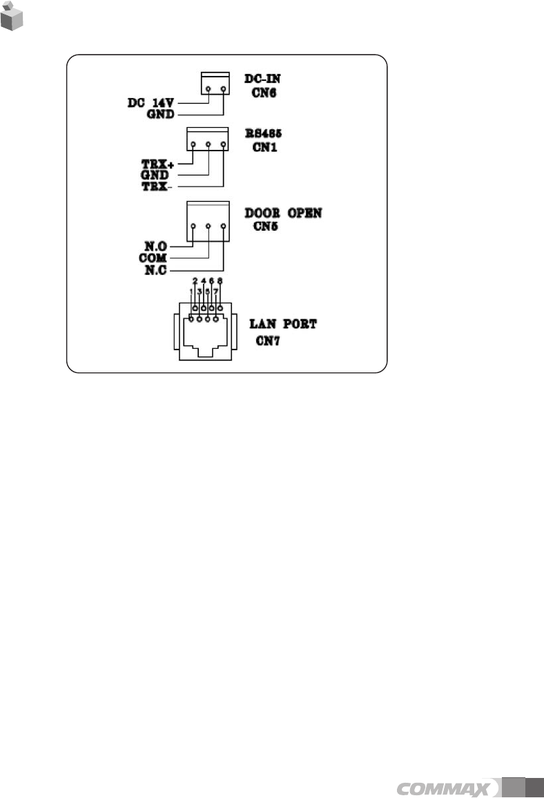
8. Wiring Diagram
Pay attention to check polarity when install lobby panel.

16
FCC Statement
15.19:
This device complies with part 15 of the FCC rules. Operation is subject to the following two
conditions: (1) This device may not cause harmful interference, and (2) This device must accept any
interference received, including interference that may cause undesired operation.
15.21:
Note: The grantee is not responsible for any changes or modifications not expressly approved by
the party responsible for compliance. Such modifications could void the user’s authority to operate
the equipment.
15.105(b):
Note: This equipment has been tested and found to comply with the limits for a Class B digital device,
pursuant to part 15 of the FCC Rules. These limits are designed to provide reasonable protection
against harmful interference in a residential installation. This equipment generates uses and can
radiate radio frequency energy and, if not installed and used in accordance with the instructions,
may cause harmful interference to radio communications. However, there is no guarantee that
interference will not occur in a particular installation. If this equipment does cause harmful interference
to radio or television reception, which can be determined by turning the equipment off and on,
the user is encouraged to try to correct the interference by one or more of the following measures:
- Reorient or relocate the receiving antenna.
- Increase the separation between the equipment and receiver.
- Connect the equipment into an outlet on a circuit different from that to which the receiver is connected.
- Consult the dealer or an experienced radio/TV technician for help.
The manufacturer, importer, and distributor shall not be liable for damages including accidental and
personal injury due to the improper use or operation of this product. The information in this
user manual was written based on current product specifications. The manufacturer, iriver Limited,
is adding new complementary features and will continue to apply new technologies in the future.
Product specifications may be changed without prior notice.
iriver is not responsible for data loss due to product use.
Disclaimers
17
Memo

513-11, Sangdaewon-dong, Jungwon-gu, Seongnam-si, Gyeonggi-do, Korea
Int’l Business Dept. Tel. : +82-31-7393-540~550 Fax. : +82-31-745-2133
Web site : www.commax.com
•Thank you for purchasing COMMAX products.
•Please carefully read this User’s Guide (in particular, precautions for safety) before using a product and follow
instructions to use a product exactly.
•The company is not responsible for any safety accidents caused by abnormal operation of the product.
Printed In Korea / 2014.10.104