COZY Furnace Wall Manual L0805260
User Manual: COZY COZY Furnace Wall Manual COZY Furnace Wall Owner's Manual, COZY Furnace Wall installation guides
Open the PDF directly: View PDF ![]() .
.
Page Count: 27
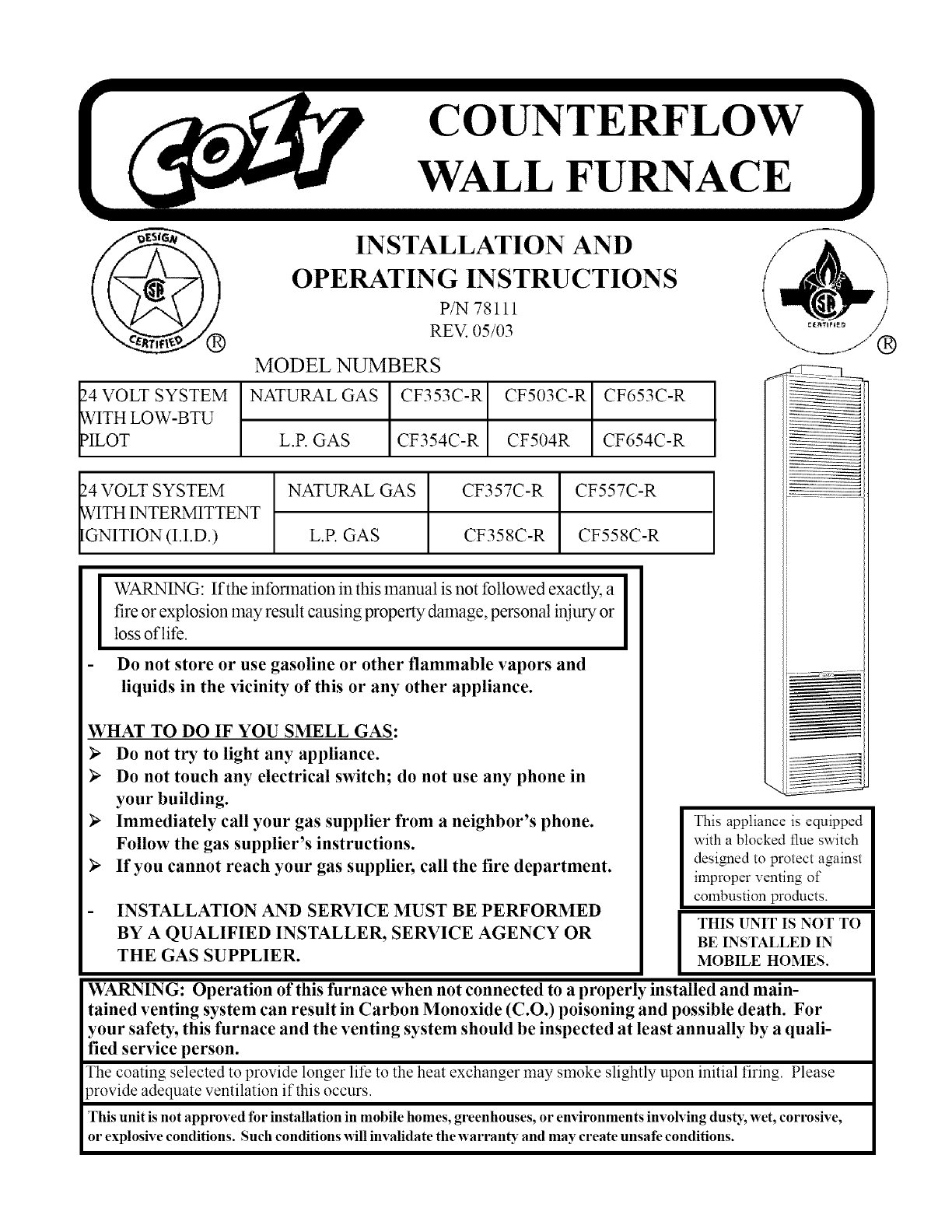
INSTALLATION AND
OPERATING INSTRUCTIONS
P/N 78111
REV. 05/03
MODEL NUMBERS
_.4VOLT SYSTEM NATURAL GAS CF353C-R CF503C-R CF653C-R
vVITH LOW-BTU
_ILOT L.P. GAS CF354C-R CF504R CF654C-R
_.4VOLT SYSTEM NATURAL GAS
_ITH INTERMITTENT
IGNITION (I.I.D.) L.P. GAS
CF357C-R
CF358C-R
CF557C-R
CF558C-R
This appliance is equipped
with a blocked flue switch
designed to protect against
improper venting of
combustion products.
THIS UNIT IS NOT TO
I WARNING: If the information in this manual is not followed exactly, a I
fire or explosion may result causing property damage, personal injury or I
loss of life.
Do not store or use gasoline or other flammable vapors and
liquids in the vicinity of this or any other appliance.
WHAT TO DO IF YOU SMELL GAS:
Do not try to light any appliance.
Do not touch any electrical switch; do not use any phone in
your building. \
)_ Immediately call your gas supplier from a neighbor's phone.
Follow the gas supplier's instructions.
)_ If you cannot reach your gas supplier, call the fire department.
INSTALLATION AND SERVICE MUST BE PERFORMED
BY A QUALIFIED INSTALLER, SERVICE AGENCY OR BE INSTALLED IN
THE GAS SUPPLIER. MOBILE HOMES.
WARNING: Operation of this furnace when not connected to a properly installed and main-
tained venting system can result in Carbon Monoxide (C.O.) poisoning and possible death. For
your safety, this furnace and the venting system should be inspected at least annually by a quali-
fied service person.
The coating selected to provide longer life to the heat exchanger may smoke slightly upon initial firing Please
)rovide adequate ventilation if this occurs.
This unit is not approved for installation in mobile homes, greenhouses, or environments involving dusK, wet, corrosive,
or explosive conditions. Such conditions _411invalidate the warran D"and may create unsafe conditions.
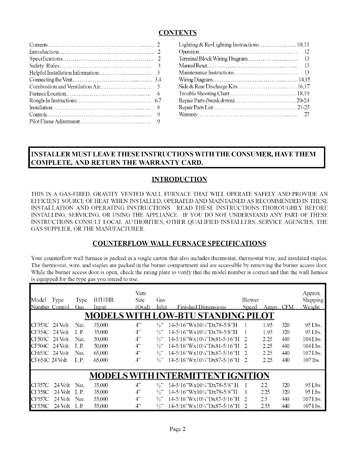
CONTENTS
Contents.............................................................. 2
Introduction ................................................. 2
Specifications ............................................... 2
Safety Rules ................................................ 3
Helpful Installation hR'onnation ............................... 3
Connecting the Vent............................................. 3,4
Combustion and Ventilation Air...................................... 5
Furnace Location................................................ 6
Rough-In Instructions ......................................... 6,7
Installation......................................................... 8
Controls............................................................. 9
Pilot Flmne Adjustment......................................... 9
Lighting & Re-Lighting Instructions .................... 10,11
Operation......................................................... 12
TerminalBlock Wiring Diammn ............................. 13
MmmalReset................................................... 13
Maintenance Instructions .................................. 13
WS-illgDiagrmn................................................. 14,15
Side & Rear Discharge Kits ................................. 16,17
Trouble Shooting Chart..................................... 18,19
Repair Parts (break down) .................................. 20-24
RepairPartsList............................................... 21-25
Whrranty......................................................... 27
IINSTALLER MUST LEAVE THESE INSTRUCTIONS WITH THE CONSUMER, HAVE THEM I
COMPLETE, AND RETURN THE WARRANTY CARD. I
INTRODUCTION
THIS IS A GAS-FIRED, GRAVITY VENTED WALL FURNACE THAT WILL OPERATE SAFELY AND PROVIDE AN
EFFICIENT SOURCE OF HEAT WHEN INSTALLED, OPERATED AND MAINTAINED AS RECOMMENDED IN THESE
INSTALLATION AND OPERATING INSTRUCTIONS. READ THESE INSTRUCTIONS THOROUGHLY BEFORE
INSTALLING, SERVICING, OR USING THE APPLIANCE. IF YOU DO NOT UNDERSTAND ANY PART OF THESE
INSTRUCTIONS CONSULT LOCAL AUTHORITIES, OTHER QUALIFIED INSTALLERS, SERVICE AGENCIES, THE
GAS SUPPLIER, OR THE MANUFACTURER.
COUNTERFLOW WALL FURNACE SPECIFICATIONS
Your counterflow wall furnace is packed in a single carton that also includes thermostat, thermostat wire, and insulated staples.
The thermostat, wire, and staples are packed in the burner compartment and are accessible by removing the burner access door.
While the burner access door is open, check the rating plate to verify that the model number is correct and that the wall furnace
is equipped t\_rthe type gas you intend to use.
Vent Approx.
Model Type Type BTUAtR. Size Gas Blower Shipping
Number Control Gas Innut (OvaB Inlet Finished Dimensions Speed Amos CFM Weight
MODELS WITH LOW-BTU STANDING PILOT
CF353C 24Volt Nat. 35,000 4" ½" 14-5/16"Wx10¼"Dx78-5/8"H 1 1.95 320 95 Lbs.
CF354C 24Volt L.R 35,000 4" ½" 14-5/16"Wx10¼"Dx78-5/8"H 1 1.95 320 95 Lbs.
CF503C 24Volt Nat. 50,000 4" ½" 14-5/16"Wx10¼"Dx81-5/16"H 2 2.25 440 104Lbs.
CF504C 24Volt L.R 50,000 4" ½" 14-5/16"Wx10¼"Dx81-5/16"H 2 2.25 440 104Lbs.
CF653C 24Volt Nat. 65,000 4" ½" 14-5/16"Wx10¼"Dx87-5/16"H 2 2.25 440 107Lbs.
CF654C 24M)lt L.R 65,000 4" ½" 14-5/16"Wx10¼"Dx87-5/16"H 2 2.25 440 1071bs.
MODELS WITH INTERMITTENT IGNITION
CF357C 24Vott Nat. 35,000 4" ½" 14-5/16"Wx10¼"Dx78-5/8"H 1 2.2 320 95 Lbs.
CF358C 24Volt L.R 35,000 4" ½" 14-5/16"Wx10¼"Dx78-5/8"H 1 2.25 320 95Lbs.
CF557C 24Volt Nat. 55,000 4" ½" 14-5/16"Wx10¼"Dx87-5/16"H 2 2.5 440 107Lbs.
CF558C 24Volt L.R 55,000 4" ½" 14-5/16"Wx10¼"Dx87-5/16"H 2 2.55 440 107Lbs.
Page 2
2.
3.
4.
5.
6.
7.
8.
9.
10.
11.
12.
13.
14.
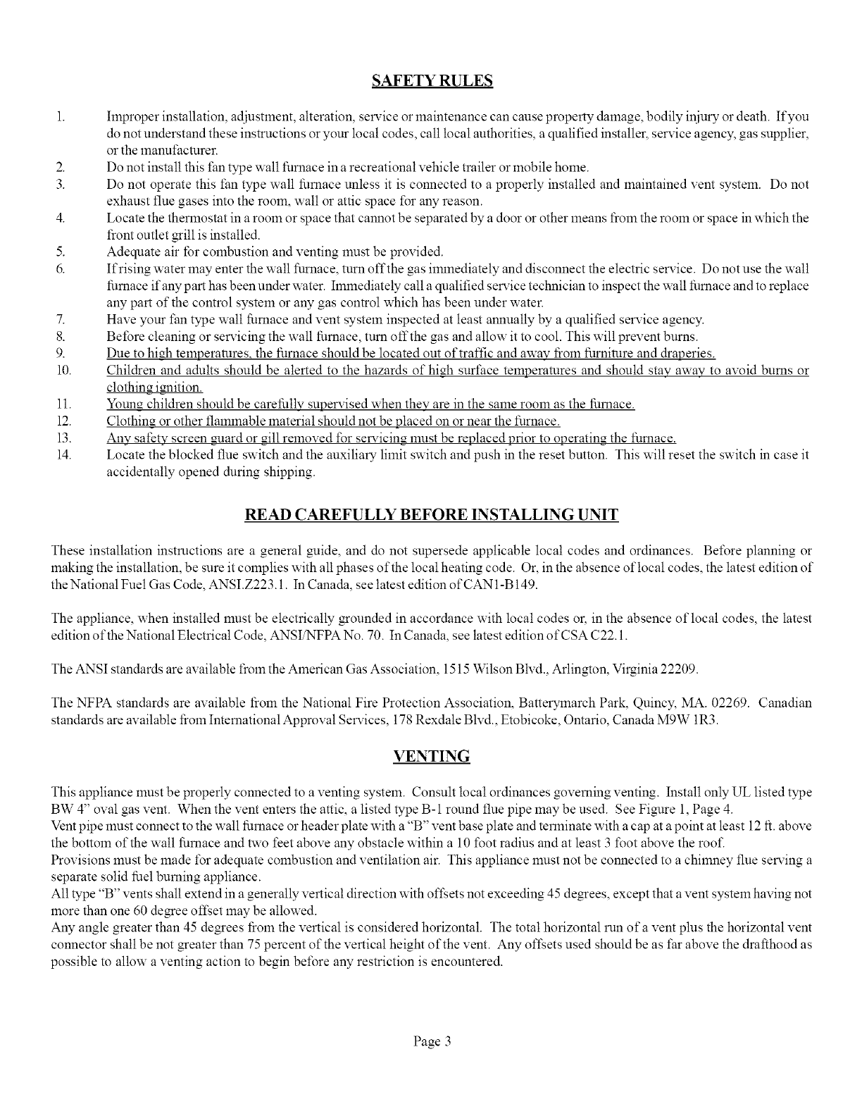
SAFETY RULES
hnproper installation, adjustment, alteration, service or maintenance can cause property damage, bodily injury or death. If you
do not understand these instructions or your local codes, call local authorities, a qualified installer, selMce agency, gas supplier,
or the manufacturer.
Do not install this fan type wall furnace in a recreational vehicle trailer or mobile home.
Do not operate this fan type wall furnace unless it is connected to a properly installed and maintained vent system. Do not
exhaust flue gases into the room, watt or attic space for any reason.
Locate the thermostat in a room or space that cannot be separated by a door or other means from the room or space in which the
front outlet grill is installed.
Adequate air for combustion and venting must be provided.
If rising water may enter the wall furnace, turn offthe gas immediately and disconnect the electric service. Do not use the wall
furnace if any part has been under water, hmnediately call a qualified service technician to inspect the walt furnace and to replace
any part of the control system or any gas control which has been under water.
Have your fan type wall furnace and vent system inspected at least annually by a qualified service agency.
Before cleaning or servicing the wall furnace, turn offthe gas and allow it to cool. This will prevent burns.
Due to high temperamres_ the furnace should be located out of traffic and away from furniture and draperies.
Children and adults should be alerted to the hazards of hi2h surface temperatures and should stay away to avoid bums or
clothing imfition.
Youn2 children should be carefully supelMsed when they are in the same room as the furnace.
Clothina or other flammable material should not be placed on or near the furnace.
Any safety screen guard or gill removed for servicin_ must be replaced prior to operating the furnace.
Locate the blocked flue switch and the auxiliary limit switch and push in the reset button. This will reset the switch in case it
accidentally opened during shipping.
READ CAREFULLY BEFORE INSTALLING UNIT
These installation instructions are a general guide, and do not supersede applicable local codes and ordinances. Belbre planning or
making the installation, be sure it complies with all phases of the local heating code. Or, in the absence oflocat codes, the latest edition of
the National Fuel Gas Code, ANSI.Z223.1. In Canada, see latest edition of CAN1-B 149.
The appliance, when installed must be electrically grounded in accordance with local codes or, in the absence of local codes, the latest
edition of the National Electrical Code, ANSI/NFPA No. 70. In Canada, see latest edition of CSA C22.1.
The ANSI standards are available from the American Gas Association, 1515 Wilson Blvd., Arlington, Virginia 22209.
The NFPA standards are available from the National Fire Protection Association, Batterymarch Park, Quincy, MA. 02269. Canadian
standards are available from International Approval Services, 178 Rexdale Blvd., Etobicoke, Ontario, Canada M9W 1R3.
VENTING
This appliance must be properly connected to a venting system. Consult local ordinances governing venting. Install only UL listed type
BW 4" oval gas vent. When the vent enters the attic, a listed type B-1 round flue pipe may be used. See Figure 1, Page 4.
Vent pipe must connect to the wall furnace or header plate with a "B" vent base plate and terminate with a cap at a point at least 12 it. above
the bottom of the wall furnace and two feet above any obstacle within a 10 lbot radius and at least 3 foot above the roof.
Provisions must be made lbr adequate combustion and ventilation air. This appliance must not be connected to a chimney flue serving a
separate solid fuel burning appliance.
All type "B" vents shall extend in a generally vertical direction with oft;ets not exceeding 45 degrees, except that a vent system having not
more than one 60 degree offset may be allowed.
Any angle greater than 45 degrees from the vertical is considered horizontal. The total horizontal mn of a vent plus the horizontal vent
connector shall be not greater than 75 percent of the vertical height of the vent. Any oft;ets used should be as far above the drafthood as
possible to allow a venting action to begin belbre any restriction is encountered.
Page 3
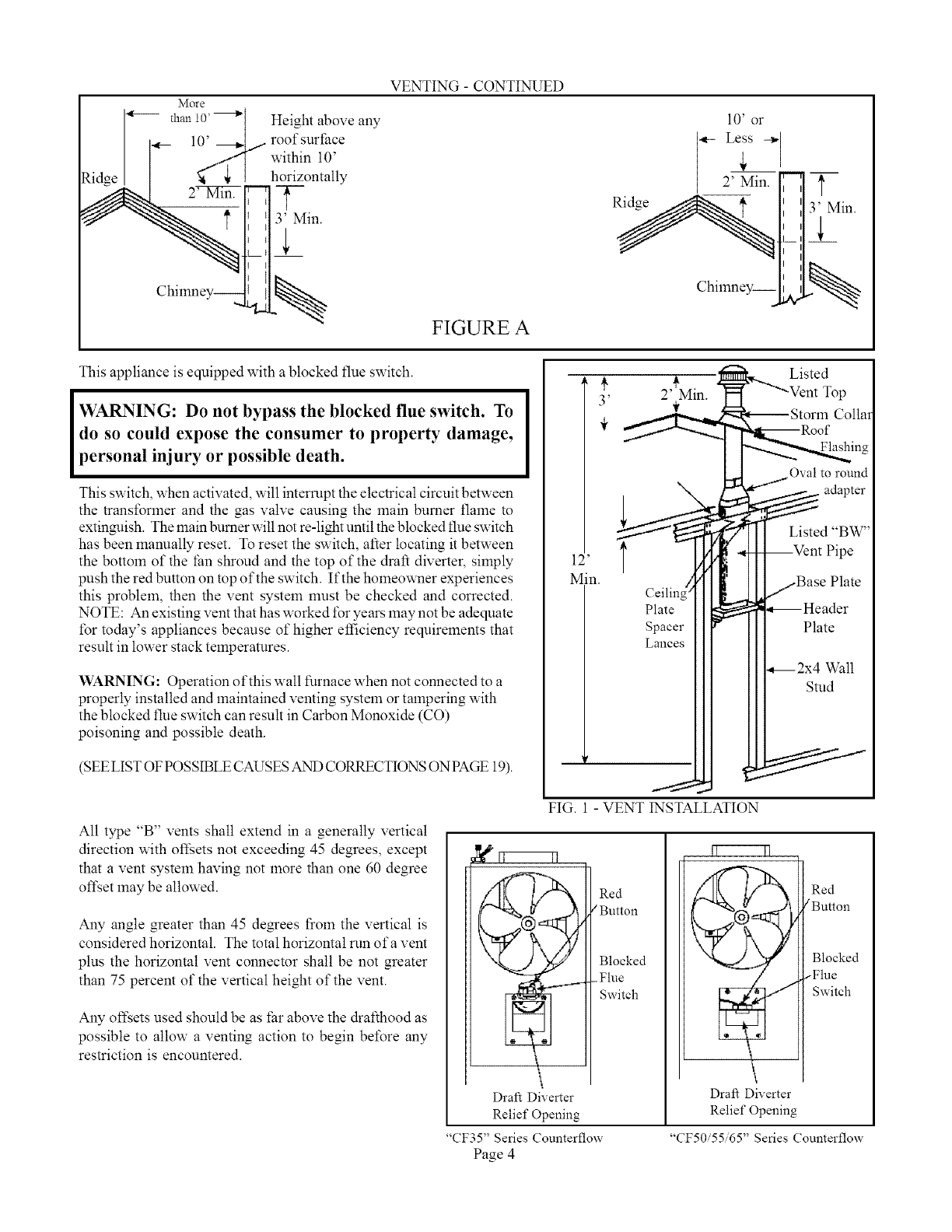
More
than 10'
_,,__ 2 Min. '1 :
I
Chimney-- I
Height above any
roof surface
within 10'
horizontally
t
3' Min.
%
VENTING- CONTINUED
FIGURE A
This appliance is equipped with a blocked flue switch.
WARNING: Do not bypass the blocked flue switch. To
do so could expose the consumer to property damage,
personal injury or possible death.
This switch, when activated, will interrupt the electrical circuit between
the transforlner and the gas valve causing the main burner flame to
extin_ish. The main burner will not re-light until the blocked flue switch
has been manually reset. To reset the switch, after locating it between
the bottom of the tan shroud and the top of the draft diverter, simply
push the red button on top of the switch. If the homeowner experiences
this problem, then the vent system must be checked and corrected.
NOTE: An existing vent that has worked for years may not be adequate
t\_r today's appliances because of higher efficiency requirements that
result in lower stack temperatures.
WARNING: Operation of this wall furnace when not connected to a
properly installed and lnaintained venting system or tampering with
the blocked flue switch can result in Carbon Monoxide (CO)
poisoning and possible death.
(SEE LIST OF POSSIBLE CAUSES AND CORRECTIONS ON PAGE 19).
All type "B" vents shall extend in a generally vertical
direction with oft;ets not exceeding 45 degrees, except
that a vent system having not more than one 60 degree
oft_et may be allowed.
Any angle greater than 45 de_ees from the vertical is
considered horizontal. The totalhorizontalrun ofavent
plus the horizontal vent connector shall be not greater
than 75 percent of the vertical height of the vent.
Any oft;ets used should be as tar above the drafthood as
possible to allow a venting action to begin before any
restriction is encountered.
12'
Min.
3' 2' Min.
t
Ceilin_
Plate
Spacer
Lances
FIG. 1 - VENT INSTALLATION
Draft Diverter
Relief Opening
"CF35" Series Counterflow
Page 4
Listed
Top
Collar
Oval to round
Listed "BW"
Pipe
Plate
Walt
Stud
Red
/Button
Blocked
_Flue
Switch
Draft Diverter
Relief Opening
Red
/Button
Blocked
_Flue
Switch
"CF50'55 65" Series Counterflow
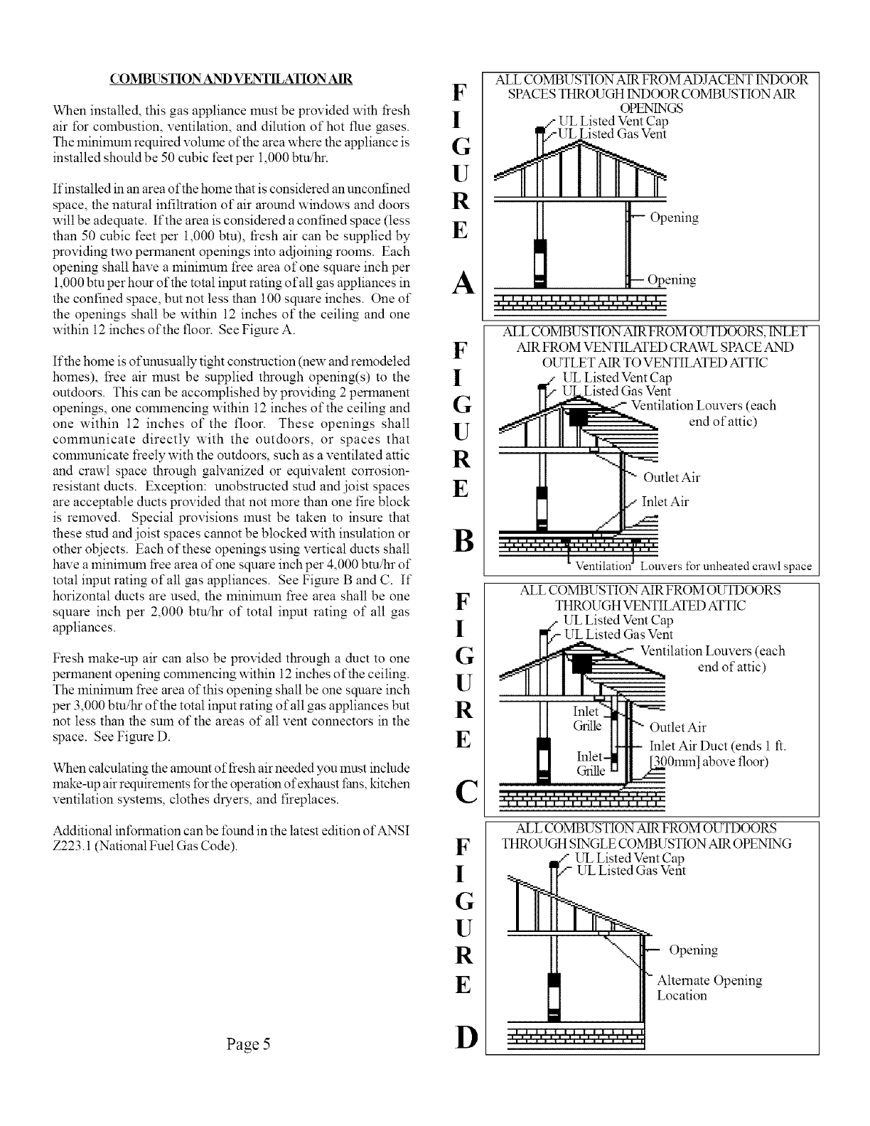
COMBUSTION AND VENTILATION AIR
When installed, this gas appliance must be provided with fiesh
air for combustion, ventilation, and dilution of hot flue gases.
The minimum required volume of the area where the appliance is
installed should be 50 cubic feet per 1,000 btu/hr.
If installed in an area of the home that is considered an unconfined
space, the natural infiltration of air around windows and doors
will be adequate. If the area is considered a confined space (tess
than 50 cubic feet per 1,000 btu), fiesh air can be supplied by
providing two permanent openings into adjoining rooms. Each
opening shall have a minilnum tree area of one square inch per
1,000 btu per horn of the total input rating of all gas appliances in
the confined space, but not less than 100 square inches. One of
the openings shall be within 12 inches of the ceiling and one
within 12 inches of the floor. See Figure A.
Ifthe home is of unusually tight construction (new and remodeled
homes), free air must be supplied through opening(s) to the
outdoors. This can be accomplished by providing 2 permanent
openings, one commencing within 12 inches of the ceiling and
one within 12 inches of the floor. These openings shall
communicate directly with the outdoors, or spaces that
comlnunicate freely with the outdoors, such as a ventilated attic
and crawl space through galvanized or equivalent conosion-
resistant ducts. Exception: unobstructed stud and joist spaces
are acceptable ducts provided that not more than one fire block
is removed. Special provisions must be taken to insure that
these stud and joist spaces cannot be blocked with insulation or
other objects. Each of these openings using vertical ducts shall
have a minimum free area of one square inch per 4,000 bm/hr of
total input rating of all gas appliances. See Figure B and C. If
horizontal ducts are used, the minimum free area shall be one
square inch per 2,000 btu/hr of total input rating of all gas
appliances.
Fresh make-up air can also be provided through a duct to one
permanent opening commencing within 12 inches of the ceiling.
The lninilnum free area of this opening shall be one square inch
per 3,000 bm/hr of the total input rating ofatl gas appliances but
not less than the sum of the areas of all vent connectors in the
space. See Figure D.
When calculating the amount of fiesh air needed you must include
make-up air requirements for the operation of exhaust fans, kitchen
ventilation systems, clothes dryers, and fireplaces.
Additional information can be f\3und in the latest edition of ANSI
Z223.1 (National Fuel Gas Code).
F
I
G
U
R
E
A
F
I
G
U
R
E
B
F
I
G
U
R
E
C
F
I
G
U
R
E
ALL COMBUSTION AIR FROM ADJACENT INDOOR
SPACES THROUGH INDOOR COMBUSTION AIR
OPENINGS
Listed Vent Cap
_ pening
Opening
tti i i t t it i t titit t
ALL COMBUSTION AIR FROM OUTDOORS, INLET
AIR FROM VENTILATED CRAWL SPACE AND
OUTLET AIR TOVENTILATED ATTIC
_Z UL Listed Vent Cap
l_.Listed Gas Vent
Ventilation Louvers (each
ff'll II endofattic)
I II II II 1"_ --.==
/
II
"- Outlet Air
/Inlet Air
_t_uvers for unheated crawl space
ALL COMBUSTION AIR FROM OUTDOORS
THROI_YGHVENTILATED ATTIC
UL Listed Vent Cap
UL Listed Gas Vent
Ventilation Louvers (each
end of attic)
Outlet Air
Inlet Air Duct (ends 1 ft.
_01rnn] above floor)
ALL COMBUSTION AIR FROM OUTDOORS
THROUGH SINGLE COMBUSTION AIR OPENING
UL Listed Vent Cap
UL Listed Gas Vent
Opening
Alternate Opening
Location
Page 5D
USING ADJACENT STUD SPACE FOR ALL
COMBUSTION AIR FROM OUTSIDE
HOLES CONNECTING TO
VENTILATED ATTIC
PLATE
AIR
GRILLE
FLOOR
HOLES CONNECTING TOVENTILATED
CRAWL SPACE
BASED ON 4,000 BTU OF TOTAL INPUT RATING
OF ALL GAS APPLIANCES, THE HEATER ONLY
REQUIRES A MINIIVRJMFREE AREA OF:
SQUARE HOLE SQUARE
BTU IN. SIZE IN.
25,000 6.25 1" .785
35,000 8.75 1.5" 1.76
50,000 12.50 2" 3.14
55,000 13.75 2.5" 4.90
65,000 16.25 3" 7.065
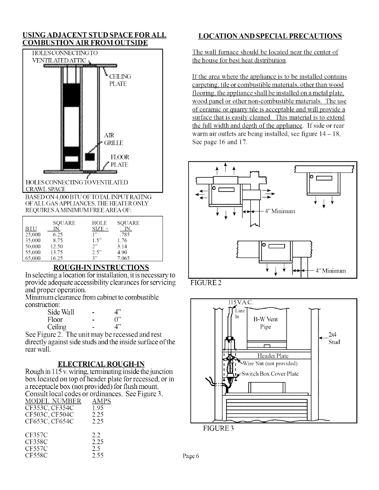
ROUGH-IN INSTRUCTIONS
In selecting a location for installation, it is necessary to
provide adequate accessibility clearances for servicing
and proper operation.
Minimum clearance from cabinet to combustible
construction:
SideWall 4"
Floor 0"
Ceiling 4"
See Figure 2. The unit may be recessed and rest
directly against side studs and the inside surface of the
rear wall.
ELECTRICAL ROUGH-IN
Rough in 115 v. wiring, terminating inside the,junction
box located on top of header plate for recessed, or in
a receptacle box (not provided) for flush mount.
Consult local codes or ordinances. See Figure 3.
MODEL NUMBER AMPS
CF353C, CF354C 1.95
CF503C, CF504C 2.25
CF653C, CF654C 2.25
CF357C 2.2
CF358C 2.25
CF557C 2.5
CF558C 2.55
LOCATION AND SPECIAL PRECAUTIONS
The wall furnace should be located near the center of
the house for best heat distribution.
If the area where the appliance is to be installed contains
carpeting, tile or combustible materials, other than wood
flooring, the appliance shall be installed on a metal plate,
wood panel or other non-combustible materials. The use
of ceramic or quarry tile is acceptable and will provide a
surt:ace that is easily cleaned. This material is to extend
the full width and depth of the appliance. If side or rear
warm air outlets are being installed, see figure 14 - lg,
See page 16 and 17.
1II ' _ o r---q
{ _ I_ -4''Minimum
_ _ 4" Minimum
FIGURE 2
ll5VA.C.
J_J_Line_
[[Ill I B_WVent
, Pip[P_
iHeader Plate
(not provided)
FIGURE 3
Z,:4
Stud
Page 6
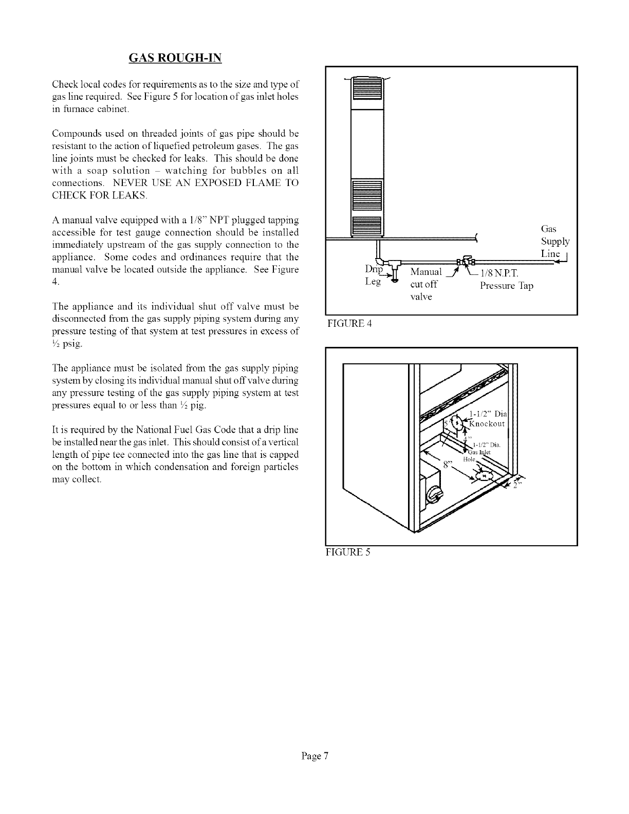
GAS ROUGH-IN
Check local codes t\_rrequirements as to the size and type of
gas line required. See Figure 5 for location of gas inlet holes
in furnace cabinet.
Compounds used on threaded joints of gas pipe should be
resistant to the action of liquefied petroleum gases. The gas
line joints must be checked t\_r leaks. This should be done
with a soap solution watching for bubbles on all
connections. NEVER USE AN EXPOSED FLAME TO
CHECK FOR LEAKS.
A manual valve equipped with a 1/8" NPT plugged tapping
accessible for test gauge connection should be installed
immediately upstream of the gas supply connection to the
appliance. Some codes and ordinances require that the
manual valve be located outside the appliance. See Figure
4.
The appliance and its individual shut off valve must be
disconnected from the gas supply piping system during any
pressure testing of that system at test pressures in excess of
V2psig.
The appliance must be isolated from the gas supply piping
system by closing its individual manual shut offvalve during
any pressure testing of the gas supply piping system at test
pressures equal to or less than ½ pig.
It is required by the National Fuel Gas Code that a drip line
be installed near the gas inlet. This should consist of a vertical
length of pipe tee connected into the gas line that is capped
on the bottom in which condensation and foreigu particles
may collect.
Gas
Supply
Lin__j
Manual j_v_ 1/8 N.P.T.
cut off Pressure Tap
valve
FIGURE 4
FIGURE 5
Page 7
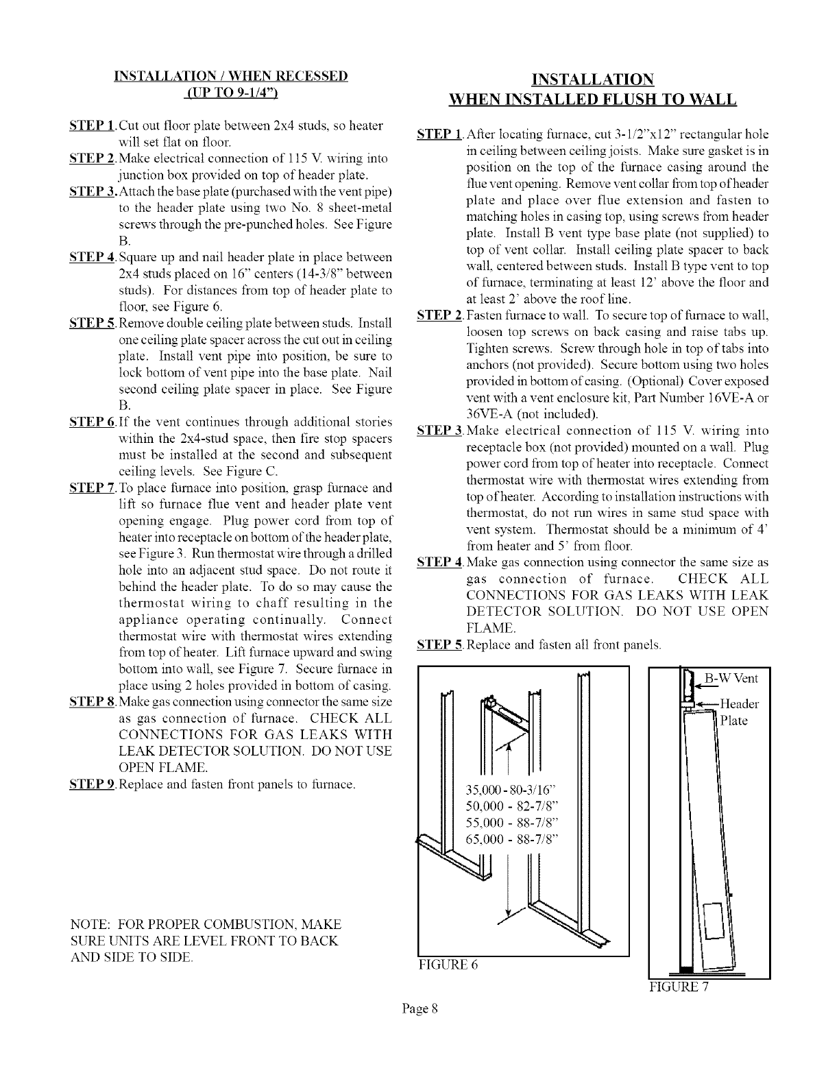
INSTALLATION /WHEN RECESSED
(UP TO 9-1/4")
STEP 1.Cut out floor plate between 2x4 studs, so heater
will set flat on floor.
STEP 2.Make electrical connection of 115 V wiring into
junction box provided on top of header plate.
STEP 3.Attach the base plate (purchased with the vent pipe)
to the header plate using two No. 8 sheet-metal
screws through the pre-punched holes. See Figure
B.
STEP 4.Square up and nail header plate in place between
2x4 studs placed on 16" centers (14-3/8" between
studs). For distances froln top of header plate to
floor, see Figure 6.
STEP 5.Remove double ceiling plate between studs. Install
one ceiling plate spacer across the cut out in ceiling
plate. Install vent pipe into position, be sure to
lock bottom of vent pipe into the base plate. Nail
second ceiling plate spacer in place. See Figure
B.
STEP 6.If the vent continues through additional stories
within the 2x4-stud space, then fire stop spacers
must be installed at the second and subsequent
ceiling levels. See Figure C.
STEP 7.To place furnace into position, grasp furnace and
lift so furnace flue vent and header plate vent
opening engage. Plug power cord from top of
heater into receptacle on bottom of the header plate,
see Figure 3. Run thermostat wire through a drilled
hole into an adjacent stud space. Do not route it
behind the header plate. To do so may cause the
thermostat wiring to chaff resulting in the
appliance operating continually. Connect
thermostat wire with thermostat wires extending
fiom top of heater. Lift furnace upward and swing
bottom into wall, see Figure 7. Secure furnace in
place using 2 holes provided in bottom of casing.
STEP 8.Make gas connection using connector the same size
as gas connection of furnace. CHECK ALL
CONNECTIONS FOR GAS LEAKS WITH
LEAK DETECTOR SOLUTION. DO NOT USE
OPEN FLAME.
STEP 9.Replace and _hsten fiont panels to furnace.
NOTE: FOR PROPER COMBUSTION, MAKE
SURE UNITS ARE LEVEL FRONT TO BACK
AND SIDE TO SIDE.
INSTALLATION
WHEN INSTALLED FLUSH TO WALL
STEP 1.After locating furnace, cut 3-1/2"xl 2" rectangular hole
in ceiling between ceiting joists. Make sure gasket is in
position on the top of the furnace casing around the
flue vent opening. Relnove vent collar from top of header
plate and place over flue extension and fasten to
matching holes in casing top, using screws fiom header
plate. Install B vent type base plate (not supplied) to
top of vent collar. Install ceiling plate spacer to back
wall, centered between studs. Install B type vent to top
of furnace, terminating at least 12' above the floor and
at least 2' above the roof line.
STEP 2.Fasten furnace to wall. To secure top of furnace to wall,
loosen top screws on back casing and raise tabs up.
Tighten screws. Screw through hole in top of tabs into
anchors (not provided). Secme bottom using two holes
providedinbottolnofcasing. (Optional) Cover exposed
vent with a vent enclosure kit, Part Number 16VE-A or
36VE-A (not included).
STEP 3.Make electrical connection of 115 V. wiring into
receptacle box (not provided) mounted on a wall. Plug
power cord from top of heater into receptacle. Connect
thermostat wire with thermostat wires extending from
top of heater. According to installation instructions with
thermostat, do not run wires in same stud space with
vent system. Thermostat should be a minimum of 4'
from heater and 5' froln floor.
STEP 4. Make gas connection using connector the same size as
gas connection of furnace. CHECK ALL
CONNECTIONS FOR GAS LEAKS WITH LEAK
DETECTOR SOLUTION. DO NOT USE OPEN
FLAME.
STEP 5. Replace and thsten all front panels.
FIGURE 6
B-W Vent
Header
ate
i
FIGURE 7
Page 8
Installation of B&V Gas Vent
%1 one-stray buildings ol %1
firs flooof 1 -so T
building_ N
Ceiling plate spacexs to centel
B-W Gas Vent m stud space -
nail _ecmely at both ends¸
width of sttld space to
Srads oi2
16 inch centers
Sheet metal screw base
plate to header
--Use maimfacmrer's method of
fastening pipe to base plate¸
Header plate of vented wail fi_nace
(also acts as fires_p)
FIGURE B
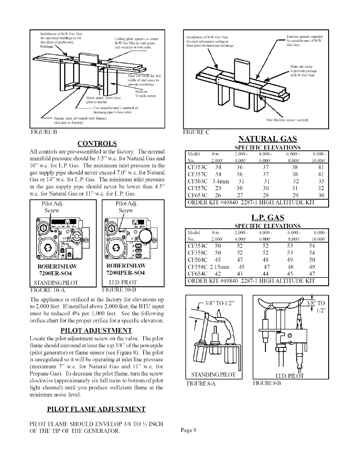
CONTROLS
All controls are pre-assembled at the factory. The normal
mani%td pressure should be 3.5" w.c. for Natural Gas and
10" w.c. tbr L.P. Gas. The maximum inlet pressure in the
gas supply pipe should never exceed 7.0" w.c. tSr Natural
Gas or 14" w.c. for L.P. Gas. The minimum inlet pressure
in the gas supply pipe should never be lower than 4.5"
w.c. for Natural Gas or 11" w.c. tbr L.P. Gas.
Pilot Adj.
Screw
,i
ROBERTSHAW
7200ER-SO4
STANDING PILOT
FIGURE 10-A
Pilot Adj.
Screw
ROBERTSHAW
7100IPER-SO4
H.D. PILOT
FIGURE 10-B
The appliance is orificed at the factory for elevations up
to 2,000 feet. If installed above 2,000 feet, the BTU input
must be reduced 4% per 1,000 feet. See the tbllowing
orifice chart for the proper orifice %r a specific elevation.
PILOT ADJUSTMENT
Locate the pilot adjustment screw on the valve. The pilot
flame should surround at least the top 3/8" of the powerpile
(pilot generator) or flame sensor (see Figure 8). The pilot
is unregulated so it will be operating at inlet line pressure
(maximum 7" w.c. for Natural Gas and 11" w.c. %r
Propane Gas). To decrease the pilot flame, turn the screw
clockwise (approximately six full turns to bottom of pilot
light channel) until you produce sufficient flame at the
minimum noise level.
PILOT FLAME ADJUSTMENT
Installation of B-W Gas Vent
fol each subsequent ceiling or
floor level ofmultistory buildings¸
Firestop spacels supplied
manut'actm el of B-W
Ga s _n_
Plate cut away
of B-Yq Ga _ E_nt
Nail filestop spacel sect e y
FIGURE CNATURAL GAS
SPECIFIC ELEVATIONS
Model 0 to 2,000 - 4,000 - &000 - 8.000 -
No. 2.000' 4.000' 6.000' 8.000' 10.000'
CF353C 34 36 37 38 41
CF357C 34 36 37 38 41
CF503C 3.4mm 31 31 32 35
CF557C 29 30 30 31 32
CF653C 26 27 28 29 30
ORDER KIT #49840 2287-1 HIGH ALTITUDE KIT
L.P. GAS
SPECIFIC ELEVATIONS
Model 0 to 2,000 - 4,000 - 6,000 - 8.000 -
No. 2.000' 4,000' 6,000' 8,000' 10,000'
CF354C 50 52 52 53 54
CF358C 50 52 52 53 54
CF504C 45 47 48 49 50
CF558C 2.15mm 45 47 48 49
CF654C 42 43 44 45 47
ORDER KIT #49840 2287-1 HIGH ALTITUDE KIT
___. 3/8" TO 1/2"
STANDING PILOT
FIGURE 8-A
' TO
1/2"
I.I.D. PILOT
FIGURE 8-B
PILOT FLAME SHOULD ENVELOP 3/8 TO V_,INCH
OF THE TIP OF THE GENERATOR. Page 9
A.
g.
WARNING:
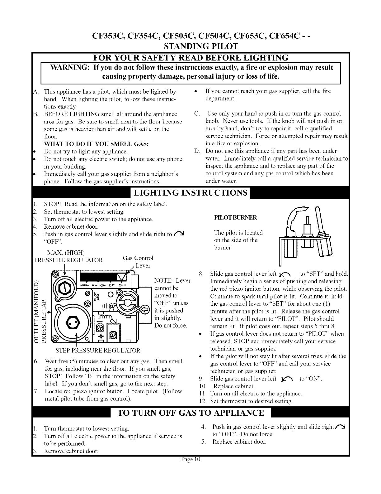
CF353C, CF354C, CF503C, CF504C, CF653C, CF654C - -
STANDING PILOT
FOR YOUR SAFETY READ BEFORE LIGHTING
If you do not follow these instructions exactly, a fire or explosion may result
causing property damage, personal injury or loss of life.
This appliance has a pilot, which must be lighted by
hand. When lighting the pilot, follow these instruc-
tions exactly.
BEFORE LIGHTING smell all around the appliance
area for gas. Be sure to smell next to the floor because
some gas is heavier than air and will settle on the
floor.
WHAT TO DO IF YOU SMELL GAS:
Do not try to light any appliance.
Do not touch any electric switch; do not use any phone
in your building.
Ilnmediately call yore gas supplier from a neighbor's
phone. Follow the gas supplier's instructions.
,, If you cannot reach your gas supplier, call the fire
department.
I
C. Use only your hand to push in or mm the gas control
kalob. Never use tools. If the kalob will not push in or
mm by hand, don't try to repair it, call a qualified
service technician. Force or attempted repair may result
in a fire or explosion.
D. Do not use this appliance if any part has been under
water. Ilnmediately call a qualified service technician to
inspect the appliance and to replace any part of the
control system and any gas control which has been
under water.
LIGHTING INSTRUCTIONS
1. STOP! Read the int\_rlnation on the safety label.
2. Set thermostat to lowest setting.
3. Turn off all electric power to the appliance.
4. Remove cabinet door.
5. Push in gas control lever slightly and slide right to i"N
"OFF".
MAX. (HIGH)
PRE SSURE REGULATOR Gas Control
©
_D
NOTE: Lever
cannot be
moved to
"OFF" unless
it is pushed
in slightly.
Do not force.
STEP PRESSURE REGULATOR
6. Wait five (5) minutes to clear out any gas. Then smell
for gas, including near the floor. If you smell gas,
STOP! Follow "B" in the int\_rlnation on the safety
label. If you don't smell gas, go to the next step.
7. Locate red piezo ignitor button. Locate pilot. (Follow
metal pilot tube from gas control).
The pilot is located
on the side of the h
burner
8. Slide gas control lever left _ to "SET" and hold
hnlnediately begin a series of pushing and releasing
the red piezo ignitor button, while observing the pilot.
Continue to spark until pilot is lit. Continue to hold
the gas control lever to "SET" for about one (1)
minute after the pilot is lit. Release the gas control
lever and it will return to "PILOT". Pilot should
remain lit. If pilot goes out, repeat steps 5 thru 8.
• If gas control lever does not return to "PILOT" when
released, STOP and immediately call your service
technician or gas supplier.
• If the pilot will not stay lit after several tries, slide the
gas control lever to "OFF" and call your service
technician or gas supplier.
9. Slide gas control lever left _ to "ON".
10. Replace cabinet.
11. Turn on all electric to the appliance.
12. Set thermostat to desired setting.
TO TURN OFF GAS TO APPLIANCE
1. Turn thermostat to lowest setting. 4.
2. Turn off all electric power to the appliance if service is
to be performed. 5.
3. Remove cabinet door.
Page 10
Push in gas control lever slightly and slide right i'X
to "OFF". Do not _\_rce.
Replace cabinet door.
CF357C, CF358C, CF557C, CF558C -I.I.D. PILOT
FOR YOUR SAFETY READ BEFORE LIGHTING
WARNING: If you do not follow these instructions exactly, a fire or explosion may result
causing property damage, personal injury or loss of life.
\. This appliance is equipped with an ignition device • If you cannot reach your gas supplier, call the tire
which automatically lights the pilot. Do not try to department.
light the pilot by hand.
BEFORE LIGHTING smell alt around the appliance C.
area for gas. Be sure to smell next to the floor
because some gas is heavier than air and will settle
on the floor.
WHAT TO DO IF YOU SMELL GAS:
Do not try to light any appliance. D.
Do not touch any electric switch; do not use any
phone in your building.
Ilnmediately call your gas supplier flom a neighbor's
phone. Follow the gas supplier's instructions.
Use only your hand to push in or mm the gas control
kalob. Never use tools. If the kalob will not push in or
mm by hand, don't try to repair it, call a qualified service
technician. Force or attempted repair may result in a tire
or explosion.
Do not use this appliance if any part has been under
water. Ilnmediatety call a qualified service technician to
inspect the appliance and to replace any part of the control
system and any gas control which has been under water.
LIGHTING INSTRUCTIONS
1. STOP! Read the int\)rlnation on the safety label.
2. Set the thermostat to its lowest setting.
3. Turn off all electric power to the appliance.
4. This appliance is equipped with an ignition device
which automatically lights the pilot. Do not try to
light the pilot by hand.
5. Remove cabinet door.
ft. Push in gas control lever slightly and slide right
to "OFF".
GAS CONTROL
LEVER
_--_[-'_ ] NOTE: Cexer
_)i_ O _ i Imovedto
pushed in
*__l slightly.
Do not
0 ibrce.
I
STEP PRESSURE REGULATOR
MAXIMUM (HIGH)
PRESSURE REGULATOR
_<
PRESSURE REGULATOR GAS CONTROL
Wait five (5) minutes to clear out aW gas. Then smell for
gas, including near the floor. If you smell gas, STOP!
Follow "B" in the information on the safety label. If you
don't smell gas, go to the next step.
Slide gas control lever left _ to "ON".
MAXIMUM (HIGH)
|LEVER
, o. (..,__.NOTE
Ir.:.. =... cannot be
moVed*o
"_ it is
_ slightly.
IN[I.._J] Donot
O force.
I
STEPPRESSURE REGULATOR
9. Replace cabinet door.
10. Turn on all electric power to the appliance.
11. Set thermostat to desired setting.
12. If the appliance will not operate, t\_llow the instructions
"TO TURN OFF GAS TO APPLIANCE" and call your
service technician or gas supplier.
TO TURN OFF GAS
1. Turn thermostat to it's lowest setting.
2. Turn off all electric power to the appliance if
service is to be performed.
3. Remove cabinet door.
TO APPLIANCE
4. Push in gas control lever slightly and slide right _ to
"OFF". Do not force.
5. Replace cabinet door.
Page 11
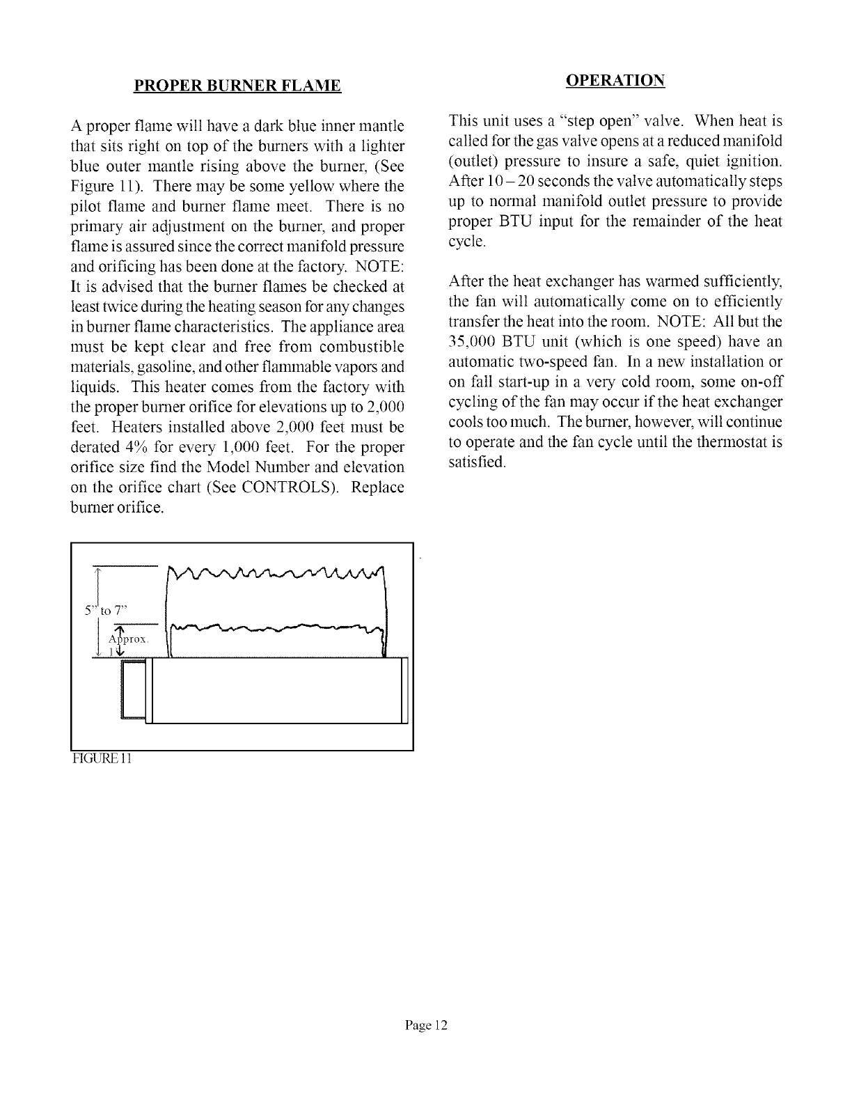
PROPER BURNER FLAME OPERATION
A proper flame will have adark blue inner mantle
that sits right on top of the burners with a lighter
blue outer mantle rising above the burner, (See
Figure 11). There may be some yellow where the
pilot flame and burner flame meet. There is no
primary air adjustment on the burner, and proper
flame is assured since the correct manifold pressure
and orificing has been done at the factory. NOTE:
It is advised that the burner flames be checked at
least twice during the heating season for any changes
in burner flame characteristics. The appliance area
must be kept clear and free from combustible
materials, gasoline, and other flamlnable vapors and
liquids. This heater comes from the factory with
the proper burner orifice for elevations up to 2,000
feet. Heaters installed above 2,000 feet must be
derated 4% for every 1,000 feet. For the proper
orifice size find the Model Number and elevation
on the orifice chart (See CONTROLS). Replace
burner orifice.
This unit uses a "step open" valve. When heat is
called for the gas valve opens at a reduced manifold
(outlet) pressure to insure a safe, quiet ignition.
After 10 - 20 seconds the valve automatically steps
up to norlnal manifold outlet pressure to provide
proper BTU input for the remainder of the heat
cycle.
After the heat exchanger has warmed sufficiently,
the tan will automatically come on to efficiently
transfer the heat into the room. NOTE: All but the
35,000 BTU unit (which is one speed) have an
automatic two-speed tan. In a new installation or
on fall start-up in a very cold room, some on-off
cycling of the fan may occur if the heat exchanger
cools too much. The burner, however, will continue
to operate and the fan cycle until the thermostat is
satisfied.
H
FIGURE 11
Page 12
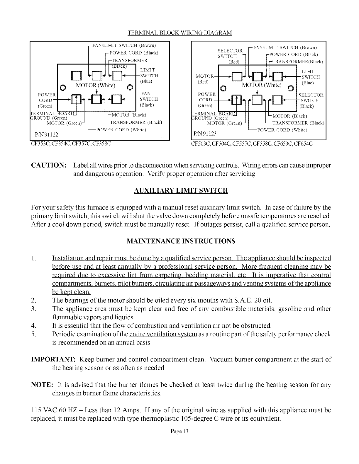
TERMINAL BLOCK WIRING DIAGRAM
-FAN/LIMIT SWITCH (Brown)
[-POWER CORD (Black)
/ IFTRANSF°R-_ER
] J L (Black) LIMIT
Ek--i ii!:
OMOTOR (White) (_
POWER _ _ FAN
dN-
(Green) (Black)
FERMINAL BOARDA l [ t-MOTOR (Black)
3ROE_rND(Green) ] L ,,V[-_:A:S;(_R_:i_
MOTOR (Green) (Black)
PO
P/N91122
CF353C, CF354C, CF357C, CF358C
I--FAN LIMIT SWITCH (Brown)
SELECTOR /
| FPOWERCORD(Black)
SWITCH 71 IF TRANSF°RMER(Black)
2_1 _ II r7 LIMIT
_,_OTOR- _L_ q II_--- SWlTC.
(Red) MOTOR.L(White) O (Blue)
O
POWER _ _ SELECTOR
CORD-------+ll1 _'_#lkA_ _'LII_---SWITCH
(Green) T/ I--I/ (Black)
FERMINAL BOARD[ [
3ROUND (Green) • I IL-'_TOsR(BI_Ik)
MOTOR (Green) _ L _-TRANFORM R (Black)
POWER CORD (White)
P/Ngl123
CF503C, CF504C, CF557C, CF558C, CF653C, CF654C
CAUTION: Label all wires prior to disconnection when servicing controls. Wiring errors can cause improper
and dangerous operation. Verify proper operation after servicing.
AUXILIARY LIMIT SWITCH
For your safety this furnace is equipped with a manual reset auxiliary limit switch. In case of failure by the
primary limit switch, this switch will shut the valve down completely before unsafe temperatures are reached.
After a cool down period, switch must be manually reset. If outages persist, call a qualified service person.
MAINTENANCE INSTRUCTIONS
.
.
3.
.
5.
Installation and repair must be done by a qualified service person. The appliance should be inspected
before use and at least annually by a professional service person. More frequent cleaning may be
required due to excessive lint from caE_eting, bedding material, etc. It is imperative that control
compartments, burners, pilot burners, circulating air passageways and venting systems of the appliance
be kept clean.
The bearings of the motor should be oiled every six months with S.A.E. 20 oil.
The appliance area must be kept clear and free of any combustible materials, gasoline and other
flammable vapors and liquids.
It is essential that the flow of combustion and ventilation air not be obstructed.
Periodic examination of the entire ventilation system as a routine part of the safety performance check
is recommended on an annual basis.
IMPORTANT: Keep burner and control compartment clean. Vacuum burner compamnent at the start of
the heating season or as often as needed.
NOTE: It is advised that the burner flames be checked at least twice during the heating season for any
changes in burner flame characteristics.
115 VAC 60 HZ - Less than 12 Amps. If any of the original wire as supplied with this appliance must be
replaced, it must be replaced with type thermoplastic 105-degree C wire or its equivalent.
Page 13
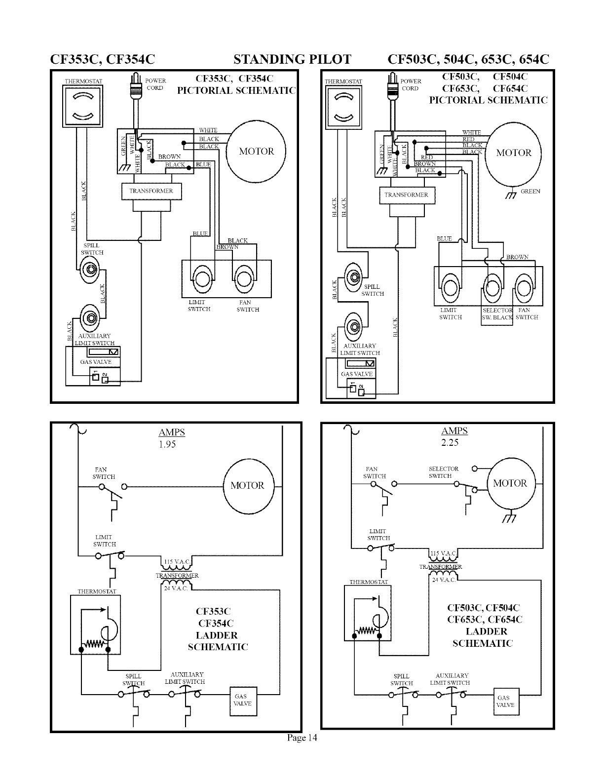
CF353C, CF354C
THEtLMO STAT POWER
+o+
SPILL
SWITCH
_5
AUXILIARY
LIMIT SWITCH
STANDING PILOT CF503C, 504C, 653C, 654C
CF353C, CF354C
PICTORIAL SCHEMATIC
BLL_
BL_CK
LIMIT FAN
S_TCH SWITCH
THERMOSTAf
SPILL
7ITCH
__! AUXILIAR,_
POWER CF503C, CF504C
cow CF653C, CF654C
PICTORIAL SCHEMATIC
BLACK
! _ /LACK
I TRANSFORMER ]
L
LIMIT SELECTO FAN
SWITCH
,O AMPS
1.95
+ @
SWITCH
-9o
LIMIT
SWITCH
TRANSFORMER
THERMOSTAf
_@ CF353C
CF354C
LADDER
q SCHEMATIC
SPILL AUXILIARY
--_-
Page 14
AMPS
2.25
FAN
SWITCH
- r0
LIMIT
SWITCH
SELECTO@:
S_ ETCH
T_R
THEP&IOSTAT
CF503C, CF504C
SPILL
SWITCH
CF653C, CF654C
LADDER
SCHEMATIC
AUXILIARY
LIMIT SWITCH
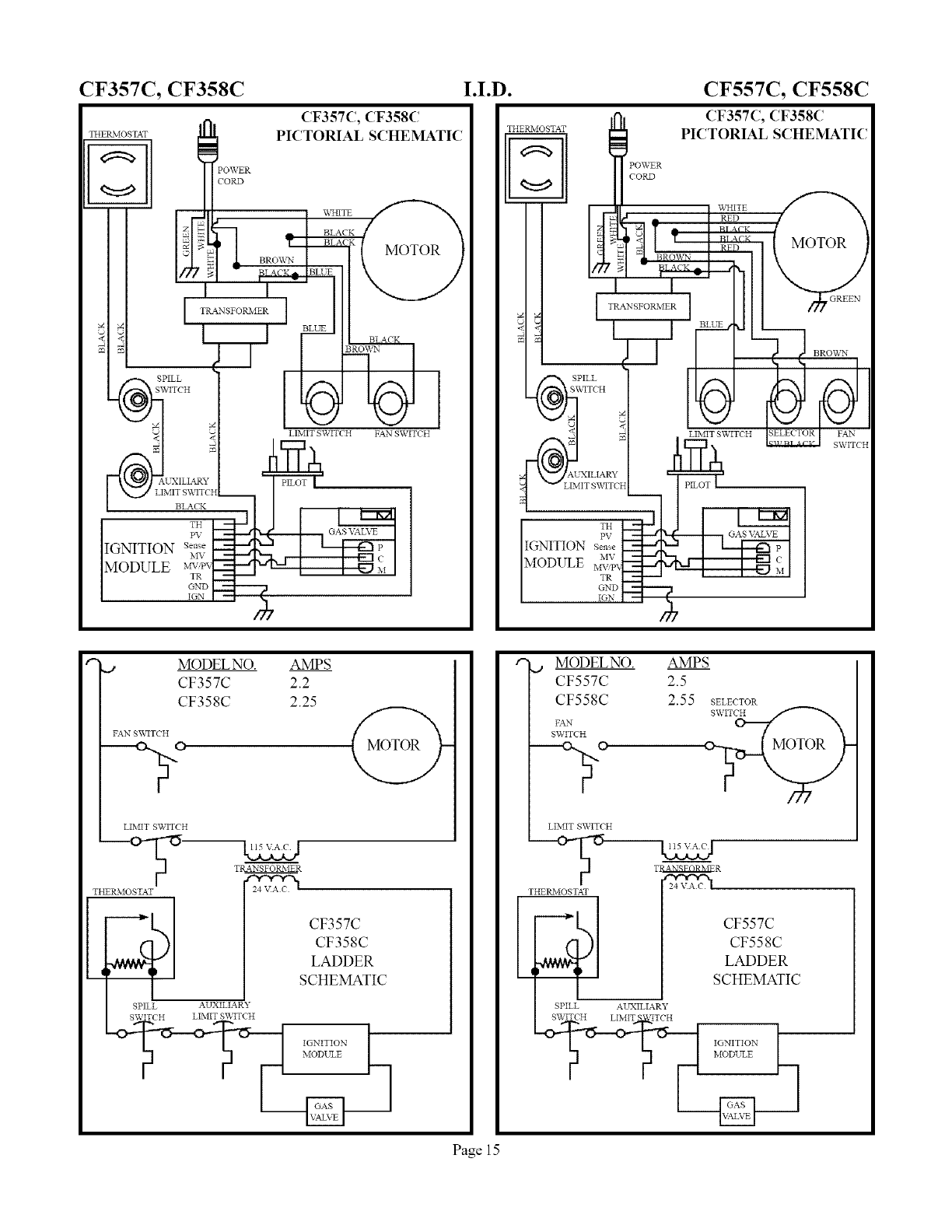
CF357C, CF358C I.I.D. CF557C, CF558C
CF357C, CF358C
TEIEPcMOSTAT PICTORIAL SCHEmaTIC
POWER
CORD
J V_IITE
,., , ,T_-%II'...._j
_. _ BLACK
SPILL _ _TCH I
VtTCH
TH
PV GAS VALVE
IGNITION s.....
MV
MODULE TR
GND
IGN
CF357C, CF358C
THERMOSTAT PICTORIAL SCHEMATIC
IT_ANSP°_'IERI Illl _.....
B2 UE
SWITCH
_ LIMIT SWITCH SELECTOR FAN
{rF?_ _ XA_cH
1 _wJLI_._LIMIT SV,_TCH
IGNITION sen_ b----7---,.k-- I _ P I
MODULE _,_;x<_ _ cII
€..,,. JMODEL NO. AMP S
CF357C 2.2
CF358C 2.25
FAN SWITCH
LIMIT SWITCH
-_ lx__
TRANSFOtLMER
THERMOSTAT 2t_4 _'_
I_@ CF357C
CF358C
LADDER
iSCHEMATIC
SPILL AUXILIARY
SWITCH LIMIT SWITCH
IGNITION
MODELNO.
CF557C
CF558C
FAN
SWITCH
AMPS
2.5
2.55 SELECTOR
I
LIMIT SWITCH
THERMOSTAT
[
SPILL AUXILIARY
SWITCH LIMIT fITCH
IGNITION
CF557C
CF558C
LADDER
SCHEMATIC
Page 15
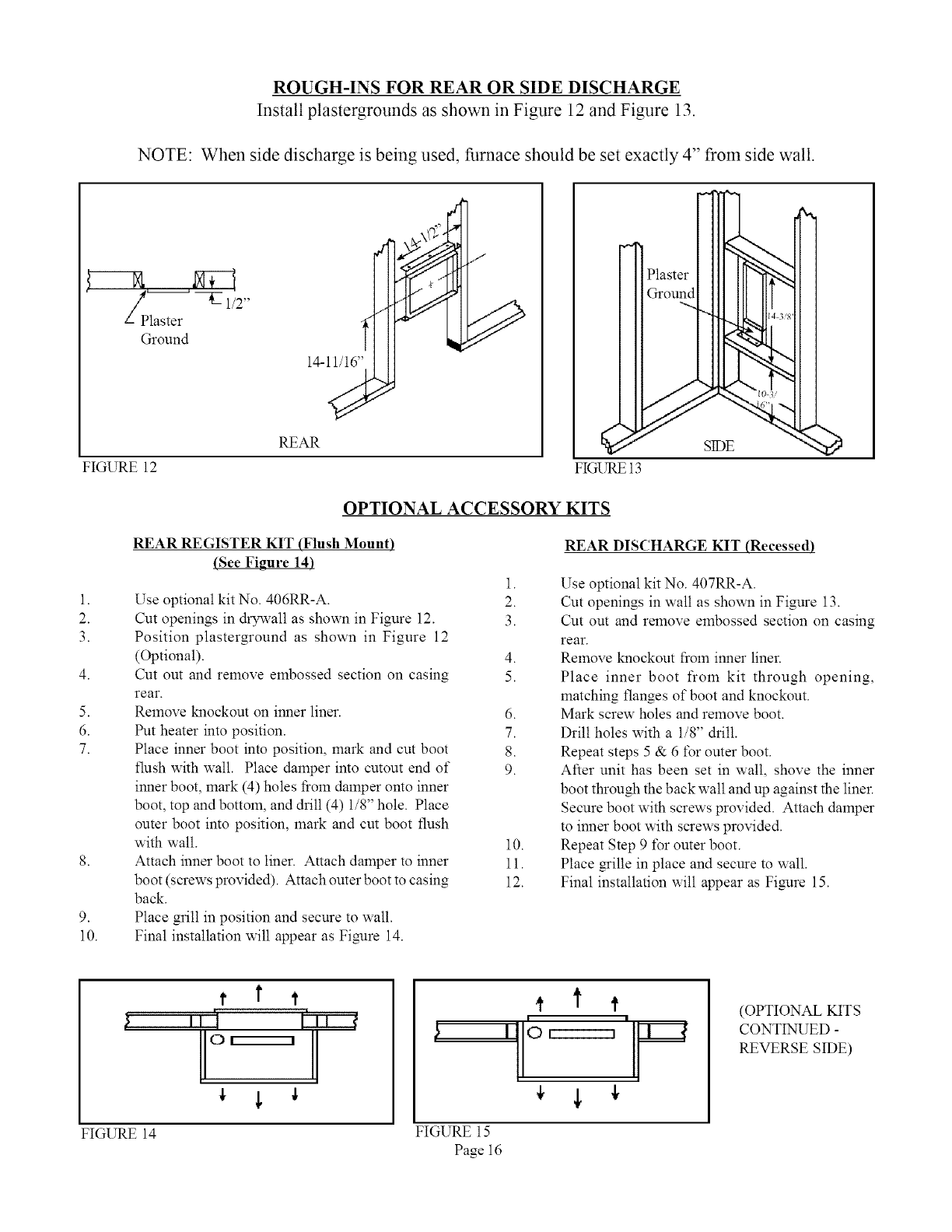
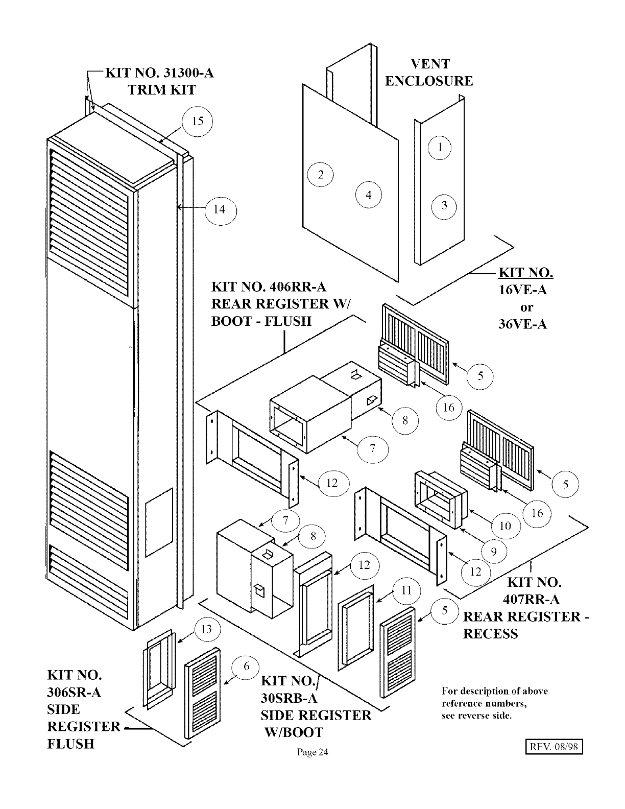
ROUGH-INS FOR REAR OR SIDE DISCHARGE
Install plastergrounds as shown in Figure 12 and Figure 13.
NOTE: When side discharge is being used, furnace should be set exactly 4" from side wall.
f--aZ/p 1/2 ,,
(;round
FIGURE 12
REAR
_ Plaster
FIGURE 13
1.
2.
3.
5.
6.
7.
9.
10.
OPTIONAL ACCESSORY KITS
REAR REGISTER KIT (Flush Mount)
(See Figure 14)
Use optional kit No. 406RR-A.
Cut openings in drywall as shown in Figure 12.
Position plasterground as shown in Figure 12
(Optional).
Cut out and remove elnbossed section on casing
rear.
Remove knockout on inner liner.
Put heater into position.
Place inner boot into position, mark and cut boot
flush with wall. Place damper into cutout end of
inner boot, mark (4) holes liom damper onto inner
boot, top and bottom, and drill (4) 1/8" hole. Place
outer boot into position, mark and cut boot flush
with wall.
Attach inner boot to liner. Attach damper to inner
boot (screws provided). Attach outer boot to casing
back.
Place grill in position and secure to wall.
Final installation will appear as Figmre 14.
1.
2.
3.
4.
5.
6.
7.
8.
9.
10.
11.
12.
REAR DISCHARGE KIT (Recessed)
Use optional kit No. 407RR-A.
Cut openings in walt as shown in Figure 13.
Cut out and remove embossed section on casing
rear.
Remove knockout from inner liner.
Place inner boot from kit through opening,
matching flanges of boot and knockout.
Mark screw holes and remove boot.
Drill holes with a 1/8" drill.
Repeat steps 5 & 6 l\_r outer boot.
After unit has been set in wall, shove the inner
boot through the back wall and up against the liner.
Secure boot with screws provided. Attach damper
to inner boot with screws provided.
Repeat Step 9 l\)r outer boot.
Place grille in place and secure to wall.
Final installation will appear as FimJre 15.
ttt
FIGURE 14
ttt
|
FIGURE 15
Page 16
(OPTIONAL KITS
CONTINUED -
REVERSE SIDE)

OPTIONAL KITS -CONTINUED
SIDE DISCHARGE ON CASING SIDE DISCHARGE (With Extension Boot)
i.
2.
3.
4.
5.
6.
7.
8.
Use optional kit No. 306SR-A.
Cut out and remove embossed area on casing side.
Remove knockout from inner liner.
Place 1-1/2" boot from kit through opening, matching
flanges of boot to knockout on inner boot.
Mark screw holes and remove boot.
Drill holes with a 1/8" &ill.
Attach inner boot with screws provided.
Place grille into position, &ill holes into casing, and
attach with screws provided.
I--tl II II II
0 r---n
4--
.
FIGURE 16
90 Degree
Outside Comer
FIGI_JRE18
MODEL Length of bottom section
NUMBER (Rel' 4) plastic raceway
CF35 5-5/16 Inches
CF50 8 Inches
CF55 14 Inches
CF65 14 Inches
NOTE: Above lengths terminate
approxilnately 2 inches above floor.
i.
2.
3.
4.
5.
6.
7.
8.
9.
Use optional kit No. 30SRB-A.
Cut opening in drywall as shown in Fig. 17.
Position plasterground as shown in Fig. 17 (optional).
Cut out and remove embossed section on casing side.
Remove knockout on inner liner.
Put heater into position.
Place inner boot into position, mark and cut boot flush with
wall. Place outer boot into position, mark and cut boot flush
with wall.
Place boot trim into position, slide inner boot through wall
from adjacent room and attach to inner liner. Slide outer
boot through wall from adjacent room and attach to casing
side.
Place grille into position and secure to wall.
III II r
I
FIGURE 17
14PEK-A PLUG EXTENSION KIT INSTRUCTIONS
FOR NON-RECESSED INSTALLATION ONLY
[;NITS WITH TERMINAL BOARD
STEP 1. Turn heater off following Section 3 in "Lighting Instructions" and allow
to cool.
STEP 2. Turn off all electricity to heater.
STEP 3. Remove top louver assembly, fan shroud and fan blade.
STEP 4. Loosen two screws on romex connector.
STEP 5. Remove junction box cover plate.
STEP 6. Disconnect three power cord temlinals and pull power cord out of top
of heater.
STEP 7. Insert power cord provided in kit through romex connector and plug
onto terminal board following wiring diagram found in lighting and
operating instructions.
STEP 8. Tighten two screws on romex connector.
STEP 9. Replace junction box cover plate.
STEP 10. Replace fan blade, fan shroud and top louver assembly.
STEP 11. Snap 90 Degree outside corner (Ref. 1) onto 3 ft. section (Ref. 2)
plastic raceway. Insert power cord and remove blue backing from
adhesive strip on raceway and apply to side of heater. See Figure 18.
STEP 12. Insert power cord into second 3 It. section of raceway (Ref. 3) and
remove blue backing and apply to side of heater, butting up agianst
bottom of other section. See Fig. 18.
STEP 13. Cut 14 inch long bottom section to required length (see chart), insert
power cord, remove backing and apply to side of heater. See Fig. 18.
STEP 14. Plug power cord into wall receptacle, see Fig.18.
STEP lg. Light the heater following lighting instructions.
Page 17
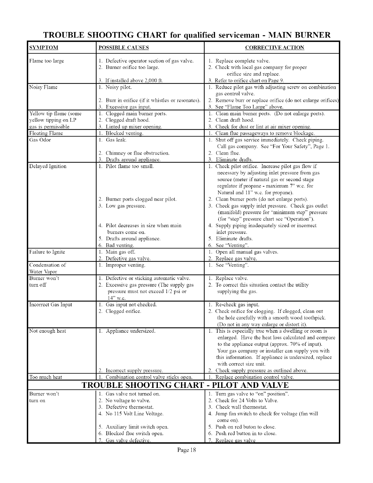
SYMPTOM
Flame too large
Noisy Flame
Yellow tip flame (some
yellow tipping on LP
_as is permissible
Floating Flame
Gas Odor
Delayed Ignition
Failure to Ignite
Condensation of
Water Vapor
Burner won't
turn off
Incorrect Gas Input
Not enough heat
Too much heat
Burner won't
turn on
TROUBLE SHOOTING CHART for qualified serviceman -MAIN BURNER
POSSIBLE CA[ SES CORRECTIVE ACTION
i. Defective operator section of'gas valve, i. Replace complete valve.
2. Burner orifice too large. 2. Check with local gas company for proper
orifice size and replace.
3. If installed above 2,000 ft. 3. Refer to orifice chart on Page 9.
1. Noisy pilot. 1. Reduce pilot gas with adjusting screw on combination
gas control valve.
2. Burr in orifice (if it whistles or resonates). 2. Remove bun" or replace orifice (do not enlarge orifices)
3. Excessive gas input. 3. See "Flame Too Large" above.
i. Clogged main burner ports. 1. Clean main burner ports. (Do not enlarge ports).
2. Clogged draft hood. 2. Clean draft hood.
3. Linted up mixer opening. 3. Check for dust or lint at air mixer opening.
i. Blocked venting, i. Clean flue passageways to remove blockage.
i. Gas leak. i. Shut off gas service immediately. Check piping.
Call gas company. See "For Your Safety", Page 1.
2. Chinmey or flue obstruction. 2. Clean flue.
3. Drafts around appliance. 3. Eliminate drafts.
1. Pilot flame too small. 1. Check pilot orifice. Increase pilot gas flow if
necessary by adjusting inlet pressure from gas
source (meter if natural gas or second stage
regulator if propane - maxinmm 7" w.c. for
Natural and 11" w.c. for propane).
2. Bumer ports clogged near pilot. 2. Clean burner ports (do not enlarge ports).
3. Low gas pressure. 3. Check gas supply inlet pressure. Check gas outlet
(manifold) pressure for "minimum step" pressure
dbr "step" pressure chart see "Operation").
4. Pilot decreases in size when main 4. Supply piping inadeqnately sized or incorrect
bumers come on. inlet pressure.
5. Drafts around appliance. 5. Eliminate drafts.
6. Bad venting. 6. See "Venting".
i. Main gas ofT. i. Open all manual gas valves.
2. Defective gas valve. 2. Replace gas valve.
I. Improper venting, i. See "Venting".
i. Defective or sticking automatic valve, i. Replace valve.
2. Excessive gas pressure (The supply gas 2. To correct this situation contact the utility
pressure must not exceed 1/2 psi or supplying the gas.
14" w.c.
i. Gas input not checked. 1. Re-check gas mput.
2. (:logged orifice. 2. Check orifice for clogging. If clogged, clean out
the hole carefully with a smooth wood toothpick.
(Do not in any way enlarge or distort it).
i. Appliance undersized, i. This is especially true when a dwelling or room is
enlarged. Have the heat loss calculated and compare
to the appliance output (approx. 70% of input).
Your gas company or installer can supply you with
this inibrmation. If appliance is undersized, replace
with con'ect size unit.
2. Incorrect supply pressure. 2. Check supply pressure as outlined above.
i. Combination control valve sticks open. i. Replace combination control valve.
TROUBLE SHOOTING CHART - PILOT AND VALVE
i. Gas valve not turned on. 1. Tuna gas valve to "on" position".
2. No voltage to valve.
3. Defective thermostat.
4. No 115 Volt Line Voltage.
5. Auxiliary limit switch open.
6. Blocked flue switch open.
7. Gas valve defective.
2. Check for 24 Volts to Valve.
3. Check wall themmstat.
4. Jump tim switch to check for voltage (fan will
conle on).
5. Push on red buton to close.
6. Push red button in to close.
7. Revlace _as valve
Page 18
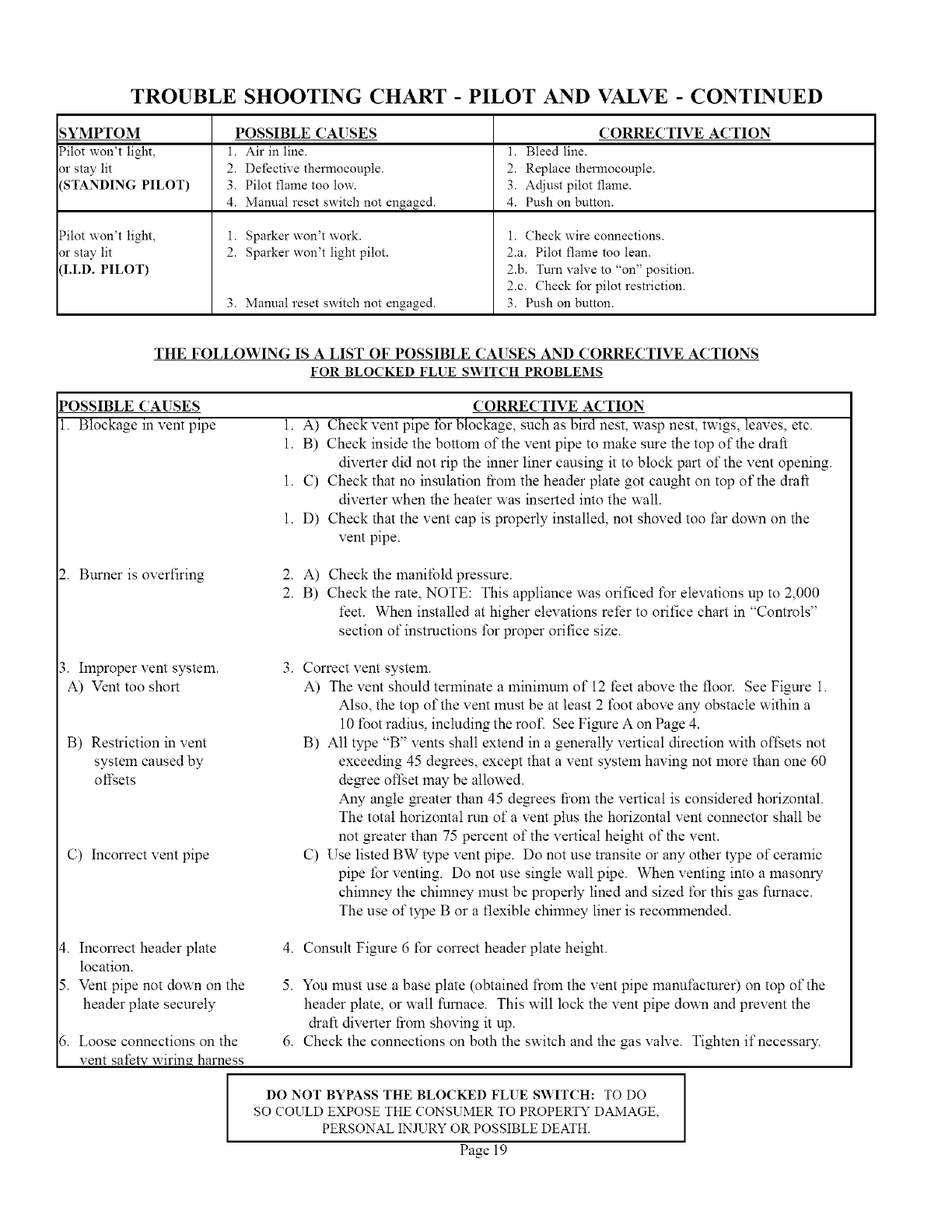
TROUBLE SHOOTING CHART - PILOT AND VALVE -CONTINUED
_YMPTOM
?ilot won't light,
3r stay lit
'STANDING PILOT)
?ilot won't light,
3r stay lit
'I.I.D. PILOT)
POSSIBLE CAUSES
1. Air in line.
2. Defective thennocouple.
3. Pilot flame too low.
4. Manual reset switch not engaged.
1. Sparker won't work.
2. Sparker won't light pilot.
3. Manual reset switch not engaged.
CORRECTIVE ACTION
1. Bleed line.
2. Replace thermocouple.
3. Adjust pilot flame.
4. Push on button.
1. Check wire connections.
2.a. Pilot flame too lean.
2.b. Turn valve to "on" position.
2.c. Check for pilot restriction.
3. Push on button.
THE FOLLOWING IS A LIST OF POSSIBLE CAUSES AND CORRECTIVE ACTIONS
FOR BLOCKED FLUE SWITCH PROBLEMS
POSSIBLE CAUSES
1. Blockage in vent pipe
CORRECTIVE ACTION
1. A) Check vent pipe tbr blockage, such as bird nest, wasp nest, twigs, leaves, etc.
1. B) Check inside the bottom of the vent pipe to make sure the top of the draft
diverter did not rip the inner liner causing it to block part of the vent opening.
1. C) Check that no insulation tiom the header plate got caught on top of the draft
diverter when the heater was inserted into the wall.
1. D) Check that the vent cap is properly installed, not shoved too far down on the
vent pipe.
2. Burner is overfiring 2. A)
2. B)
Check the manifold pressure.
Check the rate, NOTE: This appliance was orificed for elevations up to 2,000
feet. When installed at higher elevations refer to orifice chart in "Controls"
section of instructions f\_rproper orifice size.
3. Improper vent system.
A) Vent too short
B) Restriction in vent
system caused by
ofl;ets
C) Incorrect vent pipe
3. Correct vent system.
A) The vent should terminate a lninilnum of 12 feet above the floor. See Figure 1.
Also, the top of the vent must be at least 2 f\_otabove any obstacle within a
10 toot radius, including the roof. See Figure A on Page 4.
B) All type "B" vents shall extend in a generally vertical direction with ofl;ets not
exceeding 45 degrees, except that a vent system having not more than one 60
de_ee ofl;et may be allowed.
Any angle _eater than 45 de_ees from the vertical is considered horizontal.
The total horizontal run of a vent plus the horizontal vent connector shall be
not greater than 75 percent of the vertical height of the vent.
C) Use listed BW type vent pipe. Do not use transite or any other type of ceramic
pipe for venting. Do not use single wall pipe. When venting into a masonry
chimney the chimney must be properly lined and sized for this gas furnace.
The use of type B or a flexible chimney liner is recommended.
_. Incorrect header plate
location.
5. Vent pipe not down on the
header plate securely
5. Loose connections on the
4. Consult Figure 6 for correct header plate height.
5. You must use a base plate (obtained from the vent pipe manufacturer) on top of the
header plate, or wall furnace. This wilt lock the vent pipe down and prevent the
draft diverter from shoving it up.
6. Check the connections on both the switch and the gas valve. Tighten if necessary.
vent safe wirin_ harness
DO NOT BYPASS THE BLOCKED FLUE SWITCH: TO DO I
n
I
SO COULD EXPOSE THE CONSUMER TO PROPERTY DAMAGE,
PERSONAL INJURY OR POSSIBLE DEATH.
Page 19
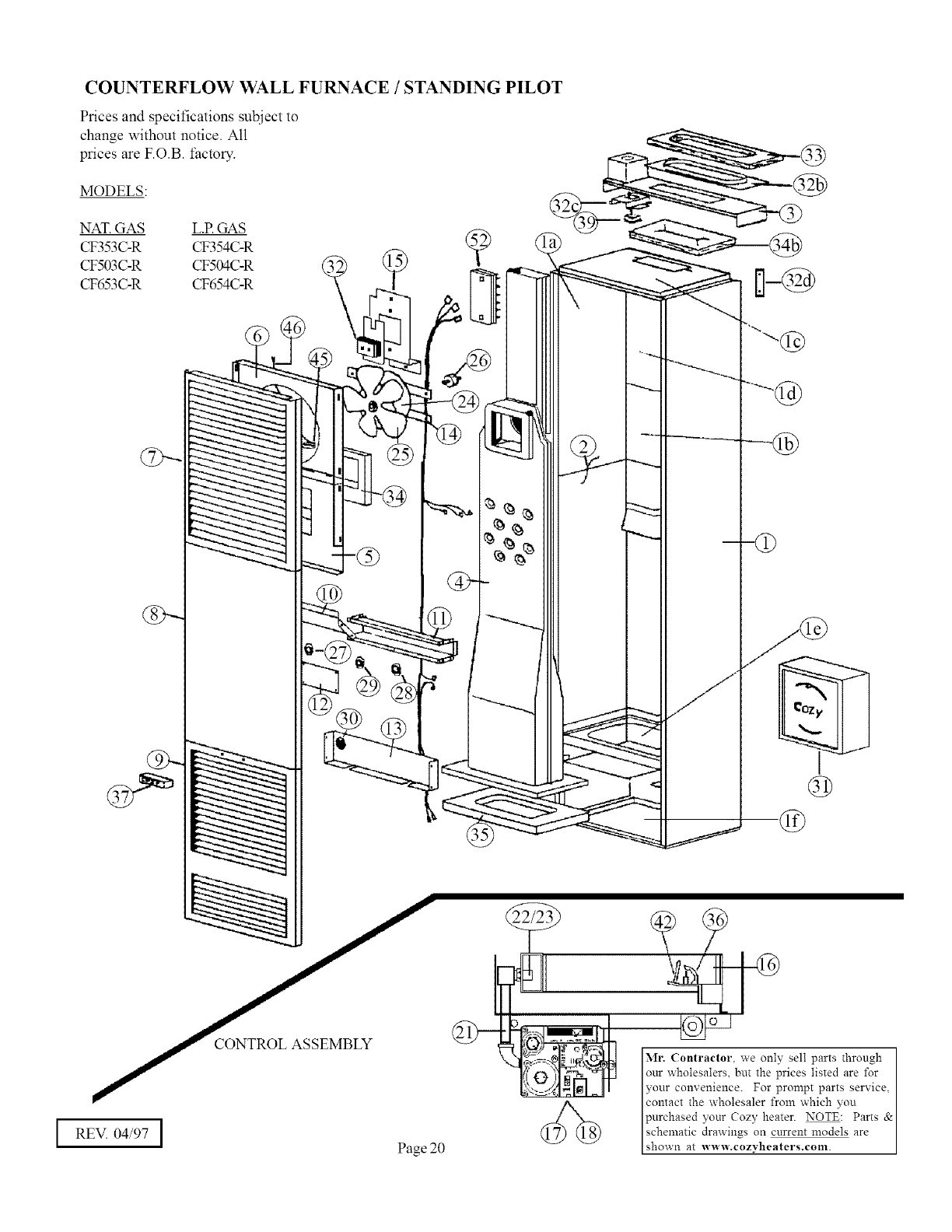
COUNTERFLOW WALL FURNACE /STANDING PILOT
Prices and specifications subject to
change without notice. All
prices are F.O.B. factory.
MODELS:
NAT.GAS L.P.GAS
CF353C-R CF354C-R
CF503C-R CF504C-R
CF653C-R CF654C-R ,,,o""_]_ [:l-@
REVI 04/97 IPage20 (_(_
Mr. Contractor, we only sell parts through
our wholesalers, but the prices listed are for I
?'our comenience. For prompt parts service,
contact the wholesaler from which you I
purchased yonr Cozy heater. NOTE: Parts &
schematic drawings on current models are
shown at www.cozyheaters.com.
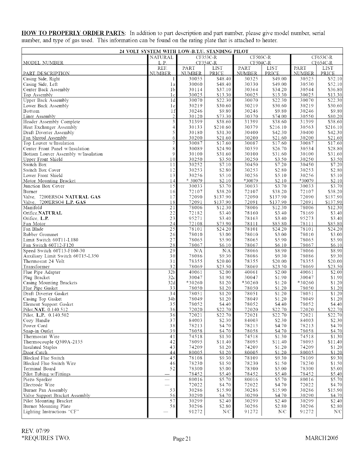
HOW TO PROPERLY ORDER PARTS: In addition to part description and part number, please give model number, serial
number, and type of gas used. This information can be found on the rating plate that is attached to heater.
MODEL NUMBER
PART DESCRIPTION
Casing Side, Right
Casing Side. Left
Center Back Assembly
Top Assembly
Upper Back Assembly
Lower Back Assembly
Bottom
Liner Assemblv
Header Assembly Complete
Heat Exchanger Assembly
Draft Diverter Assembly
Fan Shroud Assembly
Top Louver w/Insulation
Center Front Panel w Insulation
Bottom Louver Assembly w/Insulation
Upper Front Shield
Switch Box
Switch Box Cover
Lower Front Shield
Motor Mountina Bracket
Junction Box Cover
Burner
\Mve. 7200ERSO4 NATURAL GAS
Valve, 7200ERSO4 L.P. GAS
Manifold
Orifice,NATURAL
Orifice, L.P.
Fan Motor
Fan Blade
Rnbber Grommet
Limit Switch 60TI1-LIS0
Fan Switch 60T12-FI20
Speed Switch 60T13-FI60-30
Auxiliary Limit Switch 60T15-L350
24 VOLT SYSTEM WITH LOW-B.T.U. STANDING PILOT
NATURAL CF353C-R CF503C-R
L.P. CF354C-R CFS04C-R
PART LIST
NUMBER PRICE
30055 $48.40
30060 $48.40
30114 $37.10
30025 $13.30
30070 $22.30
30219 $30.60
30246 $9.80
30120 $73.30
31399 $38.60
30133 $210.60
30180 $31.30
30200 $21.60
30087 $17.60
30089 $24.90
30100 $31.60
30250 $3.50
30252 $7.10
30253 $2.80
30256 $5.10
* 30079 $2.10
30033 $3.70
72107 $38.20
72090 $137.90
72091 $137.90
78006 $12.30
72182 $3.40
95271 $3.40
72108 $73.90
78101 $24.20
78010 $3.00
78065 $5.90
78067 $6.10
HA NiA
78086 $9.30
PART LIST
N_IMBER PRICE
30325 $49.00
30330 $49.00
30364 $34.20
30025 $13.30
30070 $22.30
30219 $30.60
30246 $9.80
30370 $74.00
31399 $38.60
30379 $216.10
30400 $42.30
30200 $21.60
30087 $17.60
30359 $26.70
30100 $31.60
30250 $3.50
30450 $7.20
30253 $2.80
30256 $5.10
*30079 $2.10
30033 $3.70
72107 $38.20
72090 $137.90
72091 $137.90
78006 $12.30
78160 $3.40
78163 $3.40
78111 $85.80
78101 $24.20
78010 $3.00
78065 $5.90
78067 $6.10
78066 $8.90
78086 $9.30
Thermostat 24 Volt
Transformer
Flue Pipe Adapter
Plug Bracket
Casing Mounting Brackets
Flue Pipe Gasket
Draft Diverter Gasket
Casing Top Gasket
Element Support Gasket
Pilot.NAT. 0.140.512
Pilot, L.P.. 0.140.502
Cozy Handle
Power Cord
Snap-in Outlet
Thermostat Wire
Thermocouple Q309A-2135
Insulated Staples
Door Catch
Blocked Flue Switch
Blocked Flue Switch Wire
Terminal Board
Pilot Tubin_ w/Fittings
Piezo Sparker
Electrode Wire
Burner Pan Assembly
Valve Support Bracket Assembly
Pilot Mounting Bracket
Burner Mounting Plate
Lighting Instructions "CF'
REF.
NUMBER
1
la
lb
lc
ld
le
if
2
3
4
5
6
7
8
9
10
11
12
13
14
15
16
17
18
21
22
23
24
25
26
27
28
29
3O
31
32
32b
32c
32d
33
34
34b
35
36
36
37
38
39
41
42
43
44
45
46
52
78355
78069
40061
30047
*30260
78050
78051
78049
78052
72020
72021
84003
78213
78058
74518
78095
74209
80005
78108
78230
78300
78452
80016
72022
30286
30290
30299
30296
91272
$20.00
$23.50
$2.00
$1.90
$1.20
$1.20
$1.20
$1.20
$4.40
$22.70
$22.70
$2.30
$4.70
$4.70
$1.30
$11.40
$1.20
_1 20
$9.30
$1.50
$5.00
$5.40
$5.70
$4.70
$15.90
$4.70
$2.40
$2.80
_C
78355
78069
40061
30047
*30260
78050
78051
78049
78052
72020
72021
84003
78213
78058
74518
78095
74209
80005
78109
78230
78300
78452
80016
72022
30286
30290
30299
30296
91272
$20.00
$23.50
$2.00
$1.90
$1.20
$1.20
$1.20
$1.20
$4.40
$22.70
$22.70
$2.30
$4.70
$4.70
$1.30
$11.40
$1.20
$I 20
$9.30
$1.50
$5.00
$5.40
$5.70
$4.70
$15.90
$4.70
$2.40
$2.80
NiC
PART
N_IMBER
30525
30530
30544
30025
30070
30219
30246
30550
31399
30563
30400
30200
30087
30534
30100
30250
30450
30253
30256
*30079
30033
72107
72090
72091
78006
78169
95273
78111
78101
78010
78065
78067
78066
78086
78355
78069
40061
30047
*30260
78050
78051
78049
78052
72020
72021
84003
78213
78058
74518
78095
74209
80005
78109
78230
78300
78452
80016
72022
30286
30290
30299
30296
91272
53
56
57
58
CF653C-R
CF654C-R
LIST
PRICE
$52.10
$52.10
$36.80
$13.30
$22.30
$30.60
$9.80
$80.20
$38.60
$216.10
$42.30
$21.60
$17.60
$28.80
$31.60
$3.50
$7.20
$2.80
$5.10
$2.10
$3.70
$38.20
$137.90
$137.90
$12.30
$3.40
$3.40
$85.80
$24.20
$3.00
$5.90
$6.10
$8.90
$9.30
$20.00
$23.50
$2.00
$1.90
$1.20
$1.20
$1.20
$1.20
$4.40
$22.70
$22.70
$2.30
$4.70
$4.70
$1.30
$11.40
$1.20
$1 20
$9.30
$1.50
$5.00
$5.40
$5.70
$4.70
$15.90
$4.70
$2.40
$2.80
NiC
REV. 07/99
*REQUIRES TWO. Page 21 MARCH 2005

COUNTERFLOW WALL FURNACE /I.I.D. PILOT
Prices and specifications subject to change
without notice. All prices are F.O.B. factory.
MODELS:
NAT. GAS L.P.GAS ___
CF357C-R CF358C-R
CF557C-R CF558C-R
ASSEMBLY
Ml: Contractor. we only sell parts through our wholesalers, but
the prices listed are for your convenience. For prompt parts
service, contact the wholesaler from which you purchased your
Cozy heater. NOTE: Parts & schematic drawings on current
models are shown at www.cozyheaters.com
%
@
I:1-@
Page 22 IREV. 04/97
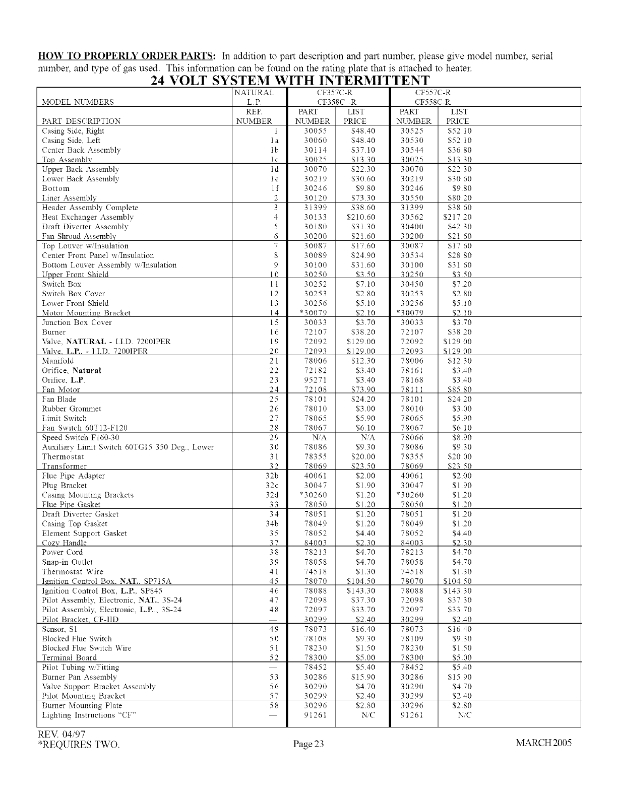
HOW TO PROPERLY ORDER PARTS: In addition to part description and part number, please give model number, serial
number, and type of gas used. This information can be found on the rating plate that is attached to heater.
24 VOLT SYSTEM WITH INTERMITTENT
NATURAL CF357C-R CF557C-R
MODEL NUMBERS L.P. CF358C -R CF558C-R
REF. PART LIST PART LIST
PART DES( RIPTION NUMBER NUMBER PRICE NUMBER PRICE
Casing Side, Right 1 30055 $48.40 30525 $52.10
Casing Side. Left la 30060 $48.40 30530 $52.10
Center Back Assembly lb 30114 $37.10 30544 $36.80
Top Assembly lc 30025 $13.30 30025 $13.30
Upper Back Assembly ld 30070 $22.30 30070 $22.30
Lower Back Assembly 1e 30219 $30.60 30219 $30.60
Bottom I f 30246 $9.80 30246 $9.80
Liner Assembly 2 30120 $73.30 30550 $80.20
Header Assembly Complete 3 31399 $38.60 31399 $38.60
Heat Exchanger Assembly 4 30133 $210.60 30562 $217.20
Draft Diverter Assembly 5 30180 $31.30 30400 $42.30
Fan Shroud Assembl'_" 6 30200 $21.60 30200 $21.60
Top Louver w/Insulation 7 30087 $17.60 30087 $17.60
Center Front Panel w/Insulation 8 30089 $24.90 30534 $28.80
Bottom Louver Assembly w/Insulation 9 30100 $31.60 30100 $31.60
Ul_t_er Front Shield 10 30250 $3.50 30250 $3.50
Switch Box 11 30252 $7.10 30450 $7.20
Switch Box (over 12 30253 $2.80 30253 $2.80
Lower Front Shield 13 30256 $5.10 30256 $5.10
Motor Mountin_ Bracket 14 *30079 $2.10 *30079 $2.10
Junction Box Cover 15 30033 $3.70 30033 $3.70
Burner 16 72107 $38.20 72107 $38.20
Valve, NATURAL - I.I.D. 7200IPER 19 72092 $129.00 72092 $129.00
Valve, L.P.. - I.I.D. 7200IPER 20 72093 $129.00 72093 $129.00
Manifold 21 78006 $12.30 78006 $12.30
Orifice, Natural 22 72182 $3.40 78161 $3.40
Orifice. L.P 23 95271 $3.40 78168 $3.40
Fan Motor 24 72108 $73.90 78111 $85.80
Fan Blade 25 78101 $24.20 78101 $24.20
Rubber Grommet 26 78010 $3.00 78010 $3.00
Limit Switch 27 78065 $5.90 78065 $5.90
Fan Switch 60T12-FI20 28 78067 $6.10 78067 $6.10
Speed Switch F160-30 29 NiA NiA 78066 $8.90
Auxiliary Limit Switch 60TG15 350 Deg., Lower 30 78086 $9.30 78086 $9.30
Thermostat 31 78355 $20.00 78355 $20.00
Transformer 32 78069 $23.50 78069 $23.50
Flue Pipe Adapter 32b 40061 $2.00 40061 $2.00
Plug Bracket 32c 30047 $1.90 30047 $1.90
Casing Mounting Brackets 32d *30260 $1.20 *30260 $1.20
Flue Pipe Gasket 33 78050 $1.20 78050 $1.20
Draft Diverter Gasket 34 78051 $1.20 78051 $1.20
Casing Top Gasket 34b 78049 $1.20 78049 $1.20
Element Support Gasket 35 78052 $4.40 78052 $4.40
Cozv Handle 37 84003 $2.30 84003 $2.30
Power Cord 38 78213 $4.70 78213 $4.70
Snap-in Outlet 39 78058 $4.70 78058 $4.70
Thermostat Wire 41 74518 $1.30 74518 $1.30
I_nition Control Box. NAT.. SPT15A 45 78070 $104.50 78070 $104.50
Ignition Control Box. L.P., SP845 46 78088 $143.30 78088 $143.30
Pilot Assembly, Electronic, NAT.. 3S-24 47 72098 $37.30 72098 $37.30
Pilot Assembl?_ Electronic, L.P.., 3S-24 48 72097 $33.70 72097 $33.70
Pilot Bracket. CF-IID 30299 $2.40 30299 $2.40
Sensor, S1 49 78073 $16.40 78073 $16.40
Blocked Flue Switch 50 78108 $9.30 78109 $9.30
Blocked Flue Switch Wire 51 78230 $1.50 78230 $1.50
Terminal Board 52 78300 $5.00 78300 $5.00
Pilot Tnbing w/Fitting 78452 $5.40 78452 $5.40
Burner Pan Assembly 53 30286 $15.90 30286 $15.90
\Idve Support Bracket Assembly 56 30290 $4.70 30290 $4.70
Pilot Mountin_ Bracket 57 30299 $2.40 30299 $2.40
Burner Mounting Plate 58 30296 $2.80 30296 $2.80
Lighting Instructions "CF" 91261 _C 91261 _C
RE_ 04/97
*REQUIRES TWO. Page 23 MARCH2005
NO. 31300-A
TRIM KIT
KIT NO. 406RR-A
REAR REGISTER W/
VENT
ENCLOSURE
NO.
16VE-A
or
36VE-A
KIT NO.
407RR-A
REAR REGISTER -
RECESS
KIT NO.
306SR-A
SIDE <.
REGISTER _
FLUSH "_--/
KIT
30SRB-A
SIDE REGISTER
W/BOOT
Page 24
For description of above
reference numbers,
see reverse side.
REV. 08/981
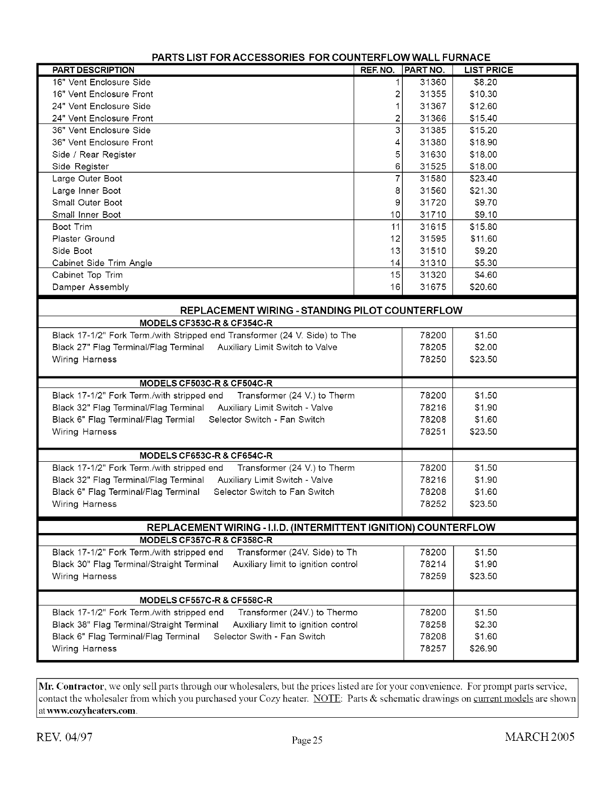
PARTS LIST FOR ACCESSORIES FOR COUNTERFLOWWALL FURNACE
PART DESCRIPTION
16" Vent Enclosure Side
16" Vent Enclosure Front
24" Vent Enclosure Side
24" Vent Enclosure Front
36" Vent Enclosure Side
36" Vent Enclosure Front
Side /Rear Register
Side Register
Large Outer Boot
Large inner Boot
Small Outer Boot
Small Inner Boot
Boot Trim
Plaster Ground
Side Boot
Cabinet Side Trim Angle
Cabinet Top Trim
Damper Assembly
REENO.
1
2
1
2
3
4
5
6
7
8
9
10
11
12
13
14
15
16
PART NO.
31360
31355
31367
31366
31385
31380
31630
31525
31580
31560
31720
31710
31615
31595
31510
31310
31320
31675
LIST PRICE
$8.20
$10.30
$12.60
$15.40
$15.20
$18.90
$18.00
$18.00
$23.40
$21.30
$9.70
$9.10
$15.80
$11.60
$9.20
$5.30
$4.60
$20.60
REPLACEMENT WIRING - STANDING PILOT COUNTERFLOW
MODELS CF353C-R & CF354C-R
Black 17-1/2" Fork Term./with Stripped end Transformer (24 V. Side) to The 78200 $1.50
Black 27" Flag Terminal/Flag Terminal Auxiliary Limit Switch to Valve 78205 $2.00
Wiring Harness 78250 $23.50
MODELS CF503C-R &CF504C-R
Black 17-1/2" Fork Term./with stripped end Transformer (24 V.) to Therm
Black 32" Flag Terminal/Flag Terminal Auxiliary Limit Switch - Valve
Black 6" Flag Terminal/Flag Termial Selector Switch - Fan Switch
Wiring Harness
MODELS CF653C-R &CF654C-R
Black 17-1/2" Fork Term./with stripped end Transformer (24 V.) to Therm
Black 32" Flag Terminal/Flag Terminal Auxiliary Limit Switch - Valve
Black 6" Flag Terminal/Flag Terminal Selector Switch to Fan Switch
Wiring Harness
78200
78216
78208
78251
78200
78216
78208
78252
$1.50
$1.90
$1.60
$23.50
$1.50
$1.90
$1.60
$23.50
REPLACEMENT WIRING - I.I.D. !INTERMITTENT IGNITION / COUNTERFLOW
MODELS CF357C-R &CF358C-R
Black 17-1/2" Fork Term./with stripped end Transformer (24V. Side) to Th
Black 30" Flag Terminal/Straight Terminal Auxiliary limit to ignition control
Wiring Harness
MODELS CF557C-R &CF558C-R
Black 17-1/2" Fork Term./with stripped end Transformer (24V.) to Thermo
Black 38" Flag Terminal/Straight Terminal Auxiliary limit to ignition control
Black 6" Flag Terminal/Flag Terminal Selector Swith - Fan Switch
Wiring Harness
78200 $1.50
78214 $1.90
78259 $23.50
78200 $1.50
78258 $2.30
78208 $1.60
78257 $26.90
Ml: Contractor, we only sell parts through our wholesalers, but the prices listed are for your convenience. For prompt parts service,
contact the wholesaler from which you purchased your Cozy heater. NOTE: Parts & schematic drawings on current models are shown
at _v.cozyheatel_.com.
REV. 04/97 Page 25 MARCH 2005
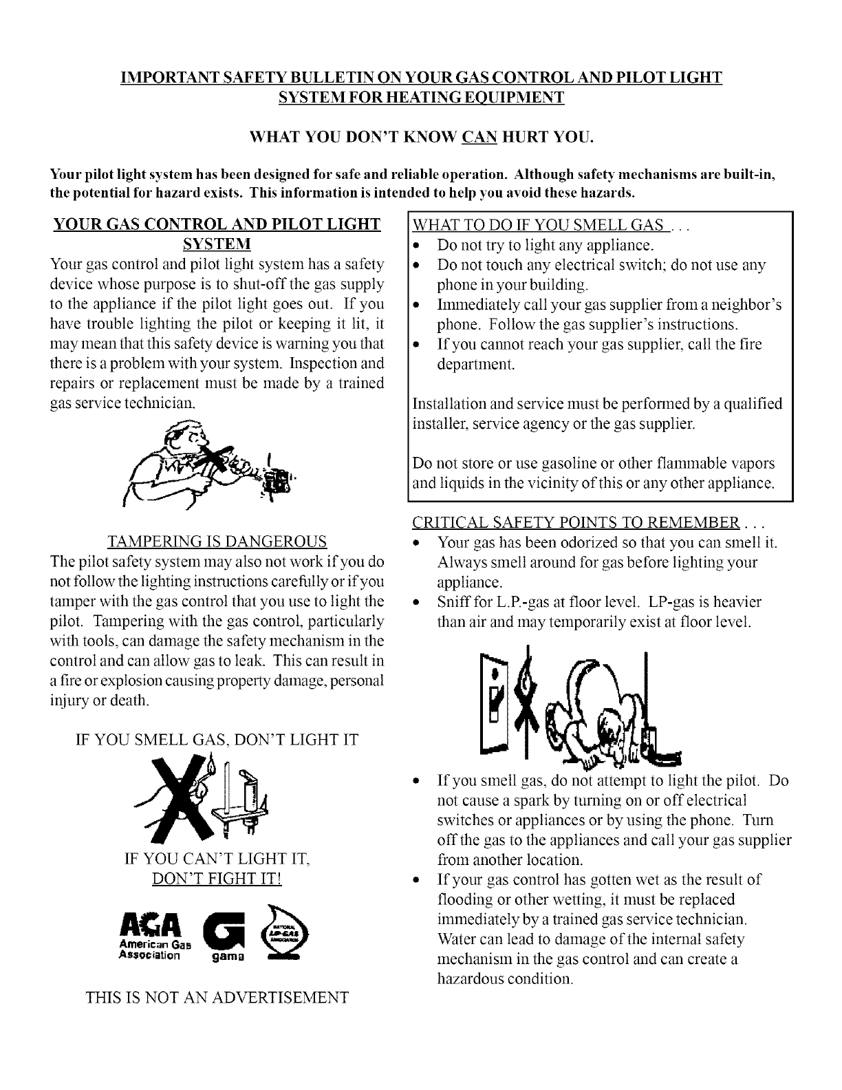
IMPORTANT SAFETY BULLETIN ON YOUR GAS CONTROL AND PILOT LIGHT
SYSTEM FOR HEATING EQUIPMENT
WHAT YOU DON'T KNOW CAN HURT YOU.
Your pilot light system has been designed for safe and reliable operation. Although safety mechanisms are built-in,
the potential for hazard exists. This information is intended to help you avoid these hazards.
YOUR GAS CONTROL AND PILOT LIGHT
SYSTEM
Your gas control and pilot light system has a safety
device whose purpose is to shut-off the gas supply
to the appliance if the pilot light goes out. If you
have trouble lighting the pilot or keeping it lit, it
may mean that this safety device is warning you that
there is a problem with your system. Inspection and
repairs or replacement must be made by a trained
gas service technician.
TAMPERING IS DANGEROUS
The pilot safety system may also not work if you do
not follow the lighting instructions carefully or if you
tamper with the gas control that you use to light the
pilot. Tampering with the gas control, particularly
with tools, can damage the safety mechanism in the
control and can allow gas to leak. This can result in
a fire or explosion causing property damage, personal
injury or death.
WHAT TO DO IF YOU SMELL GAS ...
• Do not try to light any appliance.
• Do not touch any electrical switch; do not use any
phone in your building.
• hnmediately call your gas supplier from a neighbor's
phone. Follow the gas supplier's instructions.
• If you cannot reach your gas supplier, call the fire
department.
Installation and service must be performed by a qualified
installer, service agency or the gas supplier.
Do not store or use gasoline or other flammable vapors
and liquids in the vicinity of this or any other appliance.
CRITICAL SAFETY POINTS TO REMEMBER...
• Your gas has been odorized so that you call smell it.
Always smell around for gas before lighting your
appliance.
• Sniff for L.R-gas at floor level. LP-gas is heavier
than air and may temporarily exist at floor level.
IF YOU SMELL GAS, DON'T LIGHT IT
IF YOU CAN'T LIGHT IT,
DON'T FIGHT IT!
American Ga s
Association gama
THIS IS NOT AN ADVERTISEMENT
• If you smell gas, do not attempt to light the pilot. Do
not cause a spark by turning on or off electrical
switches or appliances or by using the phone. Turn
offthe gas to the appliances and call your gas supplier
from another location.
• If your gas control has gotten wet as the result of
flooding or other wetting, it must be replaced
immediately by a trained gas service technician.
Water can lead to damage of the internal safety
mechanism in the gas control and can create a
hazardous condition.
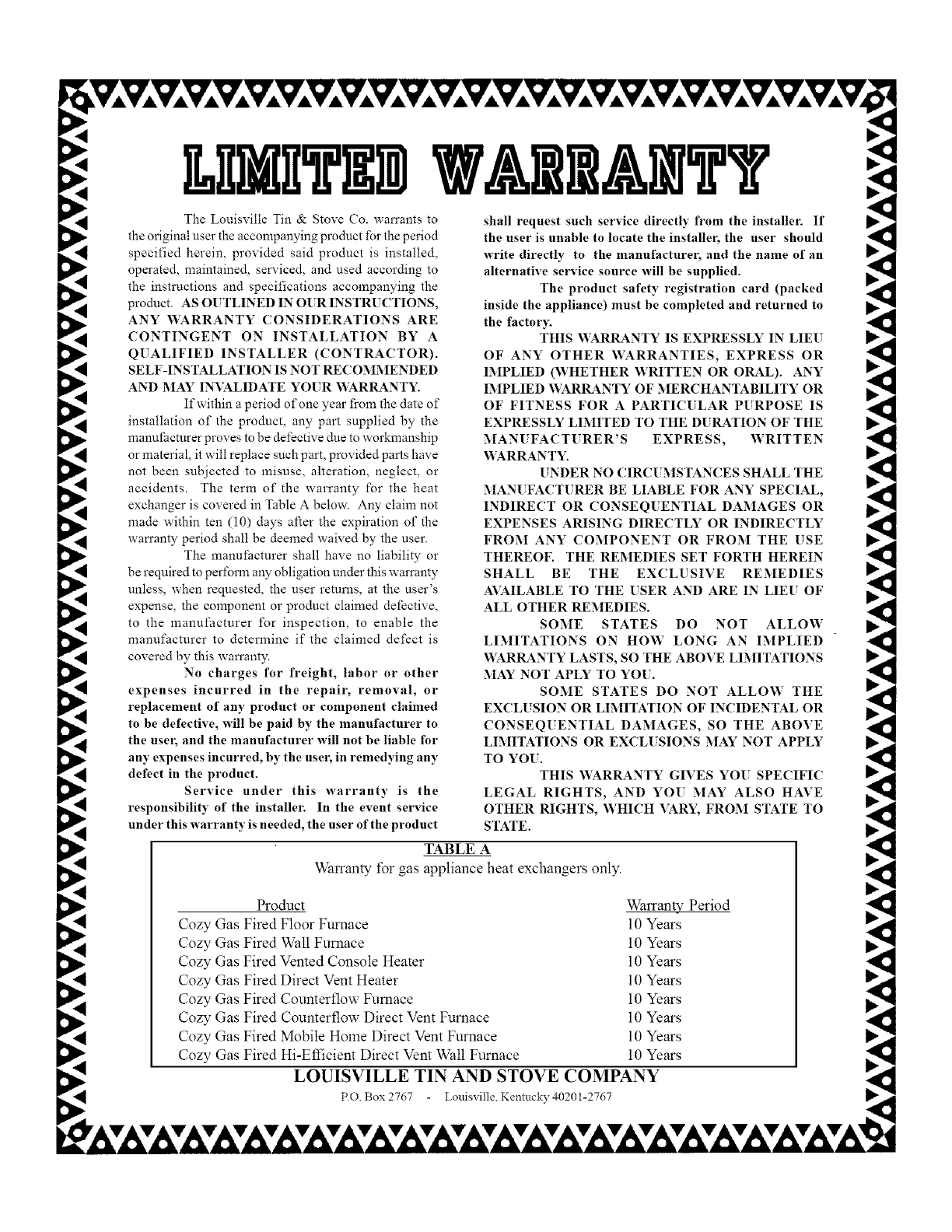
The Louisville Tin & Stove (70. warrants to
the original user the accompanying product for the period
specified herein, provided said product is installed,
operated, maintained, serviced, and used according to
the instructions and specifications accompanying the
product. AS OUTLINED IN O[ R INSTRUCTIONS,
ANY WARRANTY CONSIDERATIONS ARE
CONTINGENT ON INSTALLATION BY A
QUALIFIED INSTALLER (CONTRACTOR).
SELF-INSTALLATION IS NOT RECOMMENDED
AND MAY INVALIDATE YOUR WARRANTY.
If within a period of one year from the date of
installation of the product, any part supplied by the
manufacturer proves to be defective due to workmanship
or material, it will replace such part, provided parts have
not been subjected to misuse, alteration, neglect, or
accidents. The term of the warranty for the heat
exchanger is covered in Table A below. Any claim not
made within ten (10) days after the expiration of the
wan'anty period shall be deemed waived by the user.
The manufacturer shall have no liability or
be required to perform any obligation under this warranty
unless, when requested, the user returns, at the user's
expense, the component or product claimed defective,
to the manufacturer for inspection, to enable the
manufacturer to determine if the claimed defect is
covered by this wan'anty.
No charges for freight, labor or other
expenses incurred in the repair, removal, or
replacement of any product or component claimed
to be defective, will be paid by the manufacturer to
the user, and the manufacturer will not be liable for
any expenses incurred, by the user, in remedying any
defect in the product.
Service under this warranty is the
responsibility of the installer. In the event service
under this warranty is needed, the user of the product
shall request such service directly from the installer. If
the user is unable to locate the installer, the user should
write directly to the manufacturer, and the name of an
alternative service source will be supplied.
The product safety registration card (packed
inside the appliance) must be completed and returned to
the factor)'.
THIS WARRANTY IS EXPRESSLY IN LIEU
OF ANY OTHER WARRANTIES, EXPRESS OR
IMPLIED (WHETHER WRITTEN OR ORAL). ANY
IMPLIED WARRANTY OF MERCHANTABILITY OR
OF FITNESS FOR A PARTIC[ LAR PURPOSE IS
EXPRESSLY LIMITED TO THE D[ RATION OF THE
MAN[ FACTURER'S EXPRESS, WRITTEN
V_ARRANTY.
UNDER NO CIRC[ MSTANCES SHALL THE
MAN[ FACTURER BE LIABLE FOR ANY SPECIAL,
INDIRECT OR CONSEQ[ ENTIAL DAMAGES OR
EXPENSES ARISING DIRECTLY OR INDIRECTLY
FROM ANY COMPONENT OR FROM THE USE
THEREOF. THE REMEDIES SET FORTH HEREIN
SHALL BE THE EXCLUSIVE REMEDIES
AVAILABLE TO THE USER AND ARE IN LIEU OF
ALL OTHER REMEDIES.
SOME STATES DO NOT ALLOW
LIMITATIONS ON HOW LONG AN IMPLIED
WARRANTY LASTS, SO THE ABOVE LIMITATIONS
MAY NOT APLY TO YO[.
SOME STATES DO NOT ALLOW THE
EXCLUSION OR LIMITATION OF INCIDENTAL OR
CONSEQUENTIAL DAMAGES, SO THE ABOVE
LIMITATIONS OR EXCL[ SIONS MAY NOT APPLY
TO YO[.
THIS WARRANTY GIVES YO[ SPECIFIC
LEGAL RIGHTS, AND YO[ MAY ALSO HAVE
OTHER RIGHTS, WHICH VARY, FROM STATE TO
STATE.
TABLE A
Warranty for gas appliance heat exchangers only.
Product
Cozy Gas Fired Floor Furnace
Cozy Gas Fired Wall Furnace
Cozy Gas Fired Vented Console Heater
Cozy Gas Fired Direct Vent Heater
Cozy Gas Fired Counterflow Furnace
Cozy Gas Fired Counterflow Direct Vent Furnace
Cozy Gas Fired Mobile Home Direct Vent Furnace
Cozy Gas Fired Hi-Efficient Direct Vent Wall Furnace
Warranty Period
10 Years
10 Years
10 Years
10 Years
10 Years
10 Years
10 Years
10 Years
LOUISVILLE TIN AND STOVE COMPANY
P.O. Box 2767 Louisville_ Kentucky 40201-2767
