CRAFTSMAN Lawn, Tractor Manual 99020016
User Manual: CRAFTSMAN CRAFTSMAN Lawn, Tractor Manual CRAFTSMAN Lawn, Tractor Owner's Manual, CRAFTSMAN Lawn, Tractor installation guides
Open the PDF directly: View PDF ![]() .
.
Page Count: 52

SEARS
OWNER'S
MANUAL
MODEL NO.
944.609040
Caution:
Read and follow
all Safety Rules
and Instructions
Before Operating
This Equipment
I:RrlFTSMANo
14.5 HP
ELECTRIC START
42" MOWER
6 SPEED TRANSAXLE
LAWN TRACTOR
•Assembly
•Operation
•Customer Responsibilities
•Service and Adjustments
•Repair Parts
Sears Canada, Inc., Toronto, Ontario M5B 2B8
SAFETY RULES
Safe Operation Practices for Ride-On Mowers
IMPORTANT: THIS CUTTING MACHINE IS CAPABLE OF AMPUTATING HANDS AND FEET AND THROWING OBJECTS.
FAILURE TO OBSERVE THE FOLLOWING SAFETY INSTRUCTIONS COULD RESULT IN SERIOUS INJURY OR DEATH.
I. GENERAL OPERATION
• Read, understand,and followall instructionsin the manual
andon the machinebeforestarting.
• Only allow responsibleadults, who am familiarwith the
instructions,to operatethe machine.
•Clear the area of objectssuchas rocks, toys,wire, etc.,
whichcouldbe pickedupandthrownby the blade.
•Besurethe areaisclearofotherpeoplebeforemowing.Stop
machineif anyoneentersthe area.
•Nevercarrypassengers. ,
Donotmowinreverseunlessabsolutelynecessary.Always
lookdownand behindbeforeandwhilebacldng.
•Be awareof the mowerdischargedirectionanddonotpoint
it at anyone. Do not operatethe mowerwithouteither the
entiregrasscatcher orthe guardin place.
•Slowdown before turning.
Neverleavea running machineunattended.Alwaysturnoff
blades,set parkingbrake, stop engine,and remove keys
beforedismounting.
•Turnoff bladeswhennotmowing.
Stop enginebefore removinggrasscatcher or unclogging
chute.
Mowonlyin daylightor goodartificiallight.
Do not operate the machinewhile underthe influenceof
alcoholordrugs.
Watchfortrafficwhenoperatingnearorcrossingroadways.
•Use extra care when loadingor unloadingthe machineinto
a traileror truck.
il. SLOPE OPERATION
Slopes are a major factor related to loss-of-control and tipover
accidents, which can result in severe injury or death. All slopes
require extra caution, ifyou cannot back upthe slope or ifyou feet
uneasy on it, do not mow it.
DO:
•Mow up and down slopes, not across.
•Remove obstacles such as rocks, tree limbs, etc.
•Watch for holes, ruts, or bumps. Uneven terrain could
ovedum the machine. Tall grass can hide obstacles.
•Use slowspeed. Choose a law gear so that you will not have
to stop or shift while on the slope.
•Follow the manufacturer's recommendations for wheel
weights or counterweights to improve stability.
•Use extra care with grass catchers or other attachments.
These can change the stability of the machine.
•Keep all movement on the slopes slow and gradual. Do not
make sudden changes in speed or direction.
•Avoid starting or stopping on a slope. If tires lose traction,
disengage the blades and proceed slowly straight down the
slope.
DO NOT:
•Donottumonslopasunlessnecassary, andthen, tumslowly
and gradually downhill, if possible.
•Do not mow near drop-offs, ditches, or embankments. The
mower could suddenly turn over ifa wheel is over the edge
of a cliff or ditch, or if an edge caves in.
•Do not mow on wet grass. Reduced traction could cause
sliding.
Do not try to stabilize the machine by puttingyour footon the
ground.
•Do not use grass catcher on steep slopes.
III. CHILDREN
Tragic accidents can occur if the operator is not alert to the
presence of children. Children are often attracted to the machine
and the mowing activity. Neverassume that children will remain
where you last saw them.
•Keep children out ofthe mowing area and under the watchful
care of another responsible adult.
•Be alert and turn machine off if children enter the area.
•Before and when backing, look behind and down for small
children.
•Never carry children. They may fall off and be sedously
injured or interfere with safe machine operation.
Never allow children to operate the machine.
•Use extra care when approaching blind corners, shrubs,
tress, or other objects that may obscure vision.
IV, SERVICE
•Use extra cam inhandling gasoline and other fuels. Theyare
flammable and vapors are explosive.
Use only an approved container.
Never remove gas cap or add fuel with the engine
running. Allow engine to cool before refueling. Do not
smoke.
Never refuel the machine indoors.
Never store the machine or fuel container inside where
there is an open flame, such as a water heater.
•Never run a machine inside a closed area.
•Keep nuts and bolts, especially blade attachment bolts, tight
and keep equipment in good condition.
•Never tamper with safety devices. Check their proper
operation regularly.
•Keep machine free of grass, leaves, orother debris build-up.
Clean oil or fuel spillage. Allow machine to cool before
stodng.
•Stop and inspect the equipment if you strike an object.
Repair, ifnecessary, before restarting.
•Never make adjustments or repairs with the engine running.
Grass catcher components are subjectto wear, damage, and
deterioration, which could expose moving parts or allow
objects to be thrown. Frequently check components and
replace with manufacturer's recommended pads, when nec-
essary.
Mower blades are sharp and can cut. Wrap the blade(s) or
wear gloves, and use extra caution when servicing them.
Check brake operation frequently. Adjust and service as
required.
2
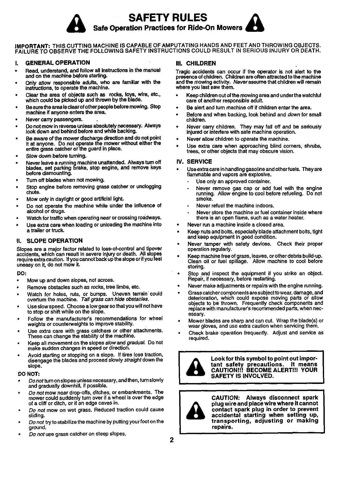
Look for this symbol to point out impor-
tant safety precautions. It means
CAUTION!H BECOME ALERTH! YOUR
SAFETY IS INVOLVED.
CAUTION: Always disconnect spark
plug wire and place wire where it cannot
contact spark plug in order to prevent
accidental starting when setting up,
transporting, adjusting or making
repairs.
CONGRATULATIONS on your purchase of a Sears
Tractor. It has been designed, engineered and manufac-
tured to give you the best possible dependability and
performance.
Should you experience any problem you cannot easily
remedy, please contact your nearest Sears Authorized
Service Centre/Depertment. We have competent, well-
trained technicians and the proper tools to service or repair
this tractor.
Please read and retain this manual. The instructions will
enable you to assemble and maintain your tractor properly.
Always observe the "SAFETY RULES".
MODEL
NUMBER
iSERIAL
NUMBER
944.609040
DATEOFPURCHASE
THEMODELANDSERIALNUMBERSWILLBEFOUND
iON A PLATE UNDER THE SEAt.
YOUSHOULDRECORDBOTHSERIALNUMBERAND
DATE OFPURCHASEANDKEEPINASAFEPLACE
FOR FUTURE REFERENCE.
MAINTENANCE AGREEMENT
A Sears Maintenance Agreement is available onthis prod-
uct. Contact your nearest Sears store for details.
CUSTOMER RESPONSIBILITIES
• Read and observe the safety rules.
Followa regular schedule in maintaining,caringforand
using your tractor.
•Follow the instructions under"Customer Responsibili-
ties" and "Storage" sections of this owner's manual.
PRODUCT SPECIFICATIONS
HORSEPOWER: 14.5
GASOLINECAPACITY 1.25 GALLONS
AND TYPE: UNLEADEDREGULAR
OILTYPE (API-SF/SG/SH): SAE 30 (above32"F)
SAE 5W-30 (below32°F)
OIL CAPACITY: 3 PINTS
SPARK PLUG: CHAMPION RC12YC
(GAP: .030")
VALVE CLEARANCE: INTAKE: ,003"-.005"
EXHAUST: .005"-.007"
GROUND SPEED (MPH): FORWARD:
1st 1.1
2nd 1.4
3rd 2.2
4th 3.3
5th 4.4
6th 4.9
REVERSE: 1.4
TIRE PRESSURE: FRONT: 14 PSI
REAR: 12 PSI
CHARGING SYSTEM: 3 AMPS BATrERY
5 AMPS HEADLIGHTS
BA'I-rERY: AMP/HR: 25
MIN. CCA: 190
CASE SIZE: UIR
iBLADEBOLTTORQUE: 27-35 FT. LBS.
WARNING: This tractor is equipped with an internal
combustion engine and should not be used on or near any
unimproved forest-covered, brush-covered or grass-cov-
ered land unless the engine's exhaust system is equipped
with a spark arrester meeting applicable local orstate laws
(if any). If a spark attester is used, it should be maintained
in effective working order by the operator.
A spark arrester for the muffler is available through your
nearest Sears Authorized Service Centre/Department (See
REPAIR PARTS section of this manual).
3

]
TABLE OF CONTENTS
SAFETY RULES ............................................................ 2
PRODUCT SPECIFICATIONS ...................................... 3
CUSTOMER RESPONSIBILITIES ..................... 3, 14-17
WARRANTY ...................................... ,........................... 4
ASSEMBLY ................................................................ 6-8
OPERATION ............................................................. 9-13
MAINTENANCE SCHEDULE ...................................... 14
SERVICE AND ADJUSTMENTS ............................ 18-22
STORAGE ................................................................... 23
TROUBLESHOOTING ..................................... ,......24.25
REPAIR PARTS -TRACTOR ................................. 28-43
REPAIR PARTS - ENGINE .................................... 44-49
PARTS ORDERING/SERVICE ................ BACK COVER
LIMITED TWO (2) YEAR WARRANTY ON CRAFTSMAN TRACTOR (RIDING EQUIPMENT)
ForTwo (2) years fromdate of purchaseSears Canada, Inc.willrepairorreplaceat Searsoptionfree of chargepartswhichare
defectiveas a resultof matadal orwodo'nanship.
FULL ONE (1) YEAR WARRANTY ON BATTERY
For One (1) year from date of purchase,if any batteryincludedwiththis ddingequipmentproves defectivein materialor
workmanshipandour testingdeterminesthe batterywillnotholda charge,Searswillreplacethe batteryat nocharge.
COMMERCIAL OR RENTAL USE
Warrantyon RidingEquipmentusedforcommercialor rentalpurposesisIimitedtoninety(90) days.
This Warranty does NOT cover:
1. Pre-dellvery sot-up.
2. Tire replacement or repair caused by punctures from outside objects (such as nails,thorns, stumps, or glass).
3. Expendable Items which become worn during normal usa, euch as blades, spark plug, air cleaners and belts.
4. Repairs necessary because of operator abuse or negligence, Including damaged Jackshaftor mandrel and the
failure to operate and maintain the equlp_nentaccordingto the Instructions contained In the Owner's Manual.
5. In Home service.
Warrantyserviceis available by ratumingthe CraftsmanRidingEquipmentto the nearestSears ServiceCantre/Departmantin
Canada. This warrantyappliesonlywhilethis productisin usein Canada.
This warrantyis in additionto any statutory warrantyand does notexclude or limit legal rightsyou may have but shall run
concurrentlywithapplicable provinciallegislation.Furthermore,some proVincesdo NOT allowlimitationon howlongan implied
warrantywill lastsothe abovelimitationsmaynotapply to you.
SEARS CANADA, INC., TORONTO, ONTARIO M5B 2B8
I
4
i i
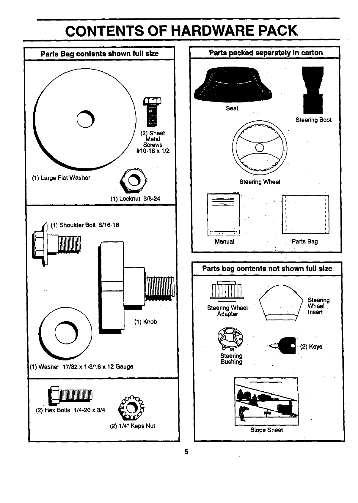
CONTENTS OF HARDWARE PACK
=
Parts Bag contents shown full size
(1) Large Flat Washer
(1) Locknut 318-24
iii
(1) Shoulder Bolt 5116-18
©mm
(1) Knob
(1) Washer 17/32 x 1-3/16 x 12 Gauge
i I
(2) Hex Bolts 1/4-20 ×3/4
(2) 1/4" Keps Nut
i
Parts packed separately in carton
Seat
Steedng Wheel
Steedng Boot
ii
Manual
li [
:I
I I
Parts Bag
Parts bag contents not shown full size
r_ _'2_%'_ Steedng
Steering Wheel Wheel
Adapter _Insert
_(2) Keys
Steering
Bushing
Slope Sheet
5
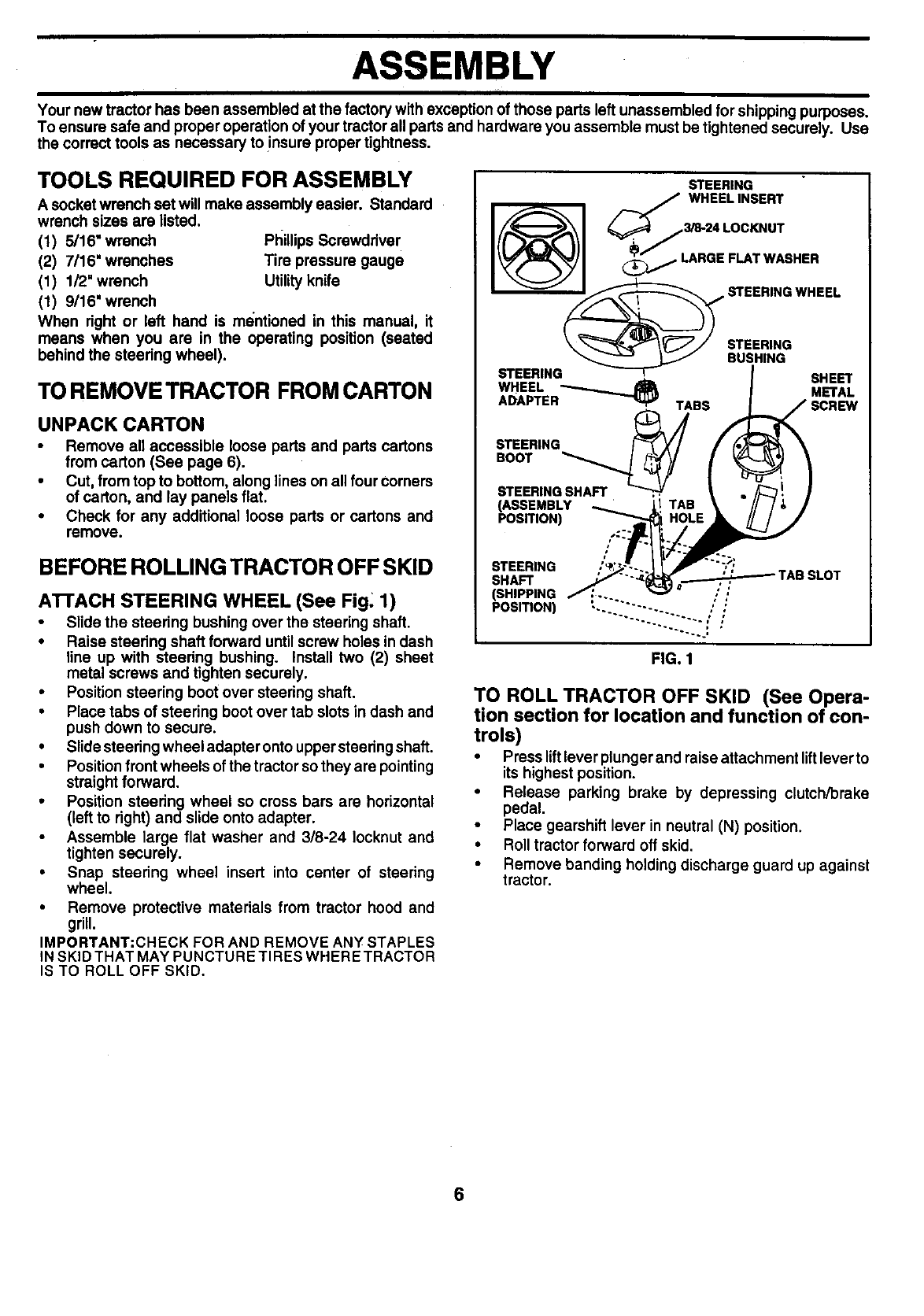
ASSEMBLY
Your new tractor has been assembled at the factory with exception of those parts left unassembled for shipping purposes.
To ensure safe and proper operation of your tractor all parts and hardware you assemble must be tightened securely. Use
the correct tools as necessary to insure proper tightness.
TOOLS REQUIRED FOR ASSEMBLY
A socket wrench set will make assembly easier. Standard
wrench sizes are listed.
(1) 5/16" wrench Phillips Screwddver
(2) 7/16" wrenches Tire pressure gauge
(1) 1/2" wrench Utility knife
(1) 9/16" wrench
When right or left hand is mentioned in this manual, it
means when you are in the operating position (seated
behind the steedng wheel).
TO REMOVETRACTOR FROM CARTON
UNPACK CARTON
• Remove all accessible loose parts and parts cartons
from carton (See page 6).
•Cut, from top to bottom, along lines on all four corners
of carton, and lay panels flat.
•Check for any additional loose parts or cartons and
remove.
BEFORE ROLLING TRACTOR OFF SKID
ATTACH STEERING WHEEL (See Fig. 1)
•Slide the steering bushing over the steering shaft.
•Raise steering shaft forward until screw holes in dash
line up with steering bushing. Install two (2) sheet
metal screws and tighten securely.
•Position steering boot over steering shaft.
•Place tabs of steering boot over tab slots in dash and
push down to secure.
•Slide steedng wheel adapter onto uppersteering shaft.
• Position front wheels of the tractor so they are pointing
straight forward.
•Position steering wheel so cross bars are horizontal
(left to right) and slide onto adapter.
•Assemble large flat washer and 3/8-24 Iocknut and
tighten securely.
•Snap steering wheel insert into center of steering
wheel.
•Remove protective materials from tractor hood and
grill.
IMPORTANT:CHECK FOR AND REMOVE ANY STAPLES
IN SKID THAT MAY PUNCTURE TIRES WHERE TRACTOR
IS TO ROLL OFF SKID.
STEERING
/_/ WHEELINSERT
_ \_// STEERING
STEERING_ BUSHING SHEET
STEERING
(ASSEMBLY
POSITION)
STEERING
SHAFT
(SHIPPING
POSITION)
FIG. 1
TO ROLL TRACTOR OFF SKID (See Opera-
tion section for location and function of con-
trols)
•Press liftlever plunger and raise attachment liftleverto
its highest position.
•Release parking brake by depressing clutch/brake
pedal.
• Place gearshift lever in neutral (N) position.
• Roll tractor forward off skid.
• Remove banding holding discharge guard up against
tractor.
6
ASSEMBLY
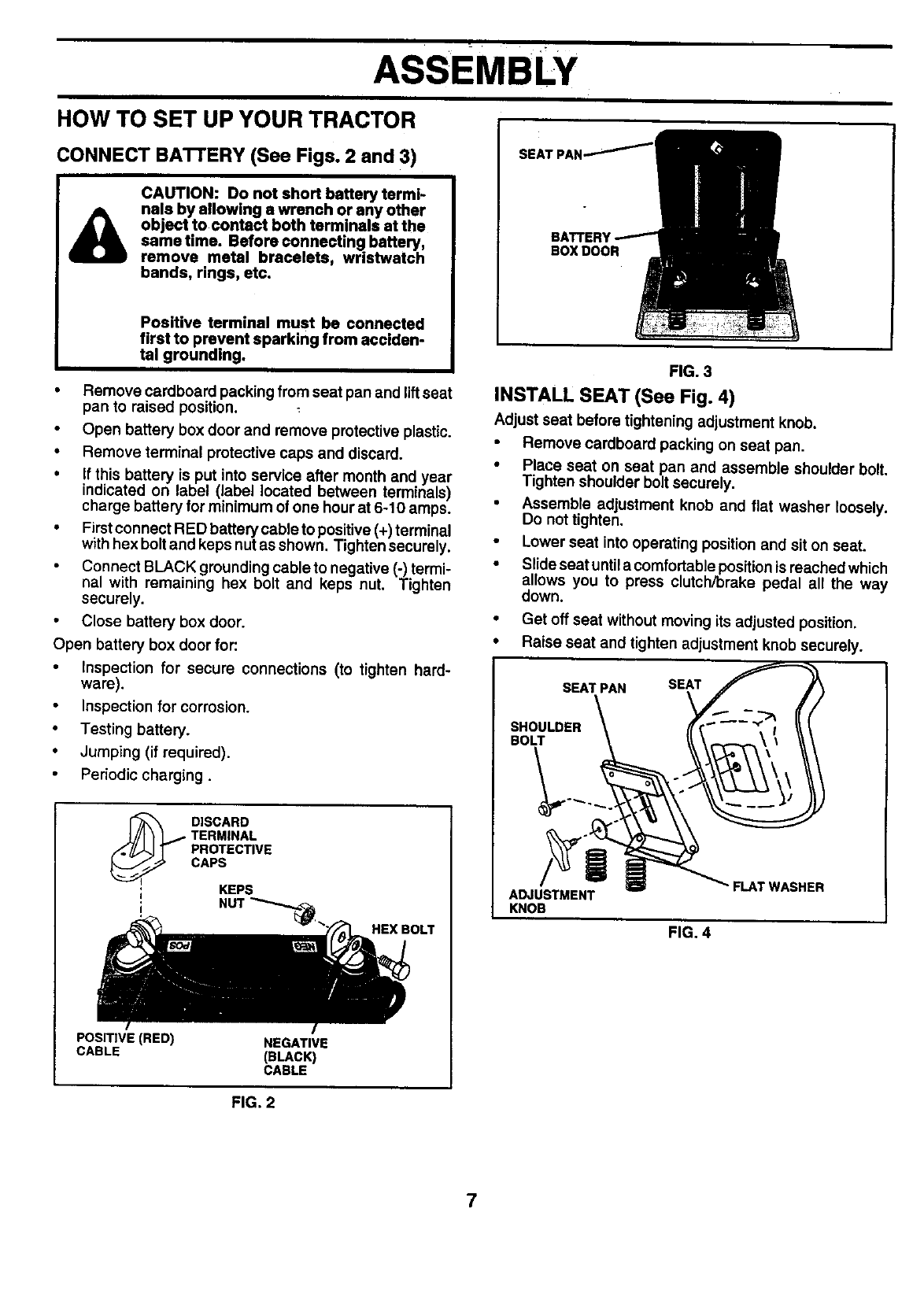
HOW TO SET UP YOUR TRACTOR
CONNECT BATI'ERY (See Figs. 2 and 3)
CAUTION: Do not short battery termi-
nals by allowing a wrench or any other
object to contact both terminals at the
same time. Before connecting battery,
remove metal bracelets, wristwatch
bands, rings, etc.
Positive terminal must be connected
first to prevent sparking from acciden-
tal grounding.
• Remove cardboard packing from seat pan and lift seat
pan to raised position.
Open battery box door and remove protective plastic.
•Remove terminal protective caps and discard.
•If this battery is put into service after month and year
indicated on label (label located between terminals)
charge battery for minimum of one hour at 6-10 amps.
•Firstconnect RED battery cable to positive (+) terminal
with hex bolt and keps nutas shown. Tighten securely.
Connect BLACK grounding cable to negative (-) termi-
nal with remaining hex bolt and keps nut. Tighten
securely.
• Close battery box door,
Open battery box door for:
•Inspection for secure connections (to tighten hard-
ware).
•Inspection for corrosion.
•Testing battery.
•Jumping (if required).
Periodic charging.
_ISCARD
TERMINAL
PROTECTIVE
CAPS
; KEPS
; NUT _._ HEX BOLT
POSITIVE (RED) NEGATIVE
CABLE (BLACK)
CABLE
FIG, 2
BOXDOOR
FIG. 3
INSTALL SEAT (See Fig. 4)
Adjust seat before tightening adjustment knob.
• Remove cardboard packing on seat pan.
•Place seat on seat pan and assemble shoulder bolt.
Tighten shoulder bolt securely.
•Assemble adjustment knob and flat washer loosely.
Do not tighten.
•Lower seat into operating position and sit on seat.
•Slide seat untila comfortable position is reached which
allows you to press clutch/brake pedal all the way
down.
•Get off seat without moving its adjusted position.
•Raise seat and tighten adjustment knob securely.
KNOB
"FLAT WASHER
FIG. 4
7
ASSEMBLY
I
,/CHECKLIST
CHECK TIRE PRESSURE
The tired on your tractor were ovednflated at the factory for
shipping purposes. Correct tire pressure is important for
best cutting performance.
• Reduce tire pressure to PSI shown in "PRODUCT
SPECIFICATIONS" on I_g¢_ 3 of this manual.
BEFORE YOU OPERATE AND ENJOY YOUR NEW
TRACTOR, WE WISH TO ASSURE THAT YOU RECEIVE
THE BEST PERFORMANCE AND SATISFACTION FROM
THIS QUALITY PRODUCT.
PLEASE REVIEW THE FOLLOWING CHECKLIST:
CHECK DECK LEVEM_E¥_
For best cutting results, mower Ii_g_'should be properly
leveled. See "TO LEVEL MOWER HOUSING" in the
Service and Adjustments section of this manual.
CHECK FOR PROPER 'POSITION OF ALL
BELTS
See the figures that are shown for replacing motion and
mower blade ddve belts in the Service and Adjustments
section of this manual. Verify that the belts are routed
correctly.
CHECK BRAKE SYSTEM
After you learn how to operate your tractor, check to see
that the brake is properly adjusted. See "TO ADJUST
BRAKE" in the Service and Adjustments section of this
manual.
/All assembly instructions have been completed.
/No remaining loose parts in carton.
,/ Battery is properly prepared and charged. (Minimum
1 hour at 6 amps).
,/ Seat is adjusted comfortably and tightened securely.
/All tires are propedy inflated. (For shipping purposes,
the tires were overmflated at the factory).
,/ Be sure mower deck is properly leveled side-to-side/
front-to-rear for best cutting results. (Tires must be
properly inflated for leveling).
,/ Check mower and ddve belts. Be sure they are routed
properly around pulleys and inside all belt keepers.
,/ Check wiring. See that all connections are stillsecure
and wires are properly clamped.
WHILE LEARNING HOW TO USE YOUR TRACTOR, PAY
EXTRA ATTENTION TO THE FOLLOWING IMPORTANT
ITEMS:
/Engine oil is at proper level.
,/ Fuel tank is filled with fresh, clean, regular unleaded
gasoline.
/Become familiar with all controls - their location and
function. Operate them before you start the engine.
/Be sure brake system is in safe operating condition.
8
OPERATION
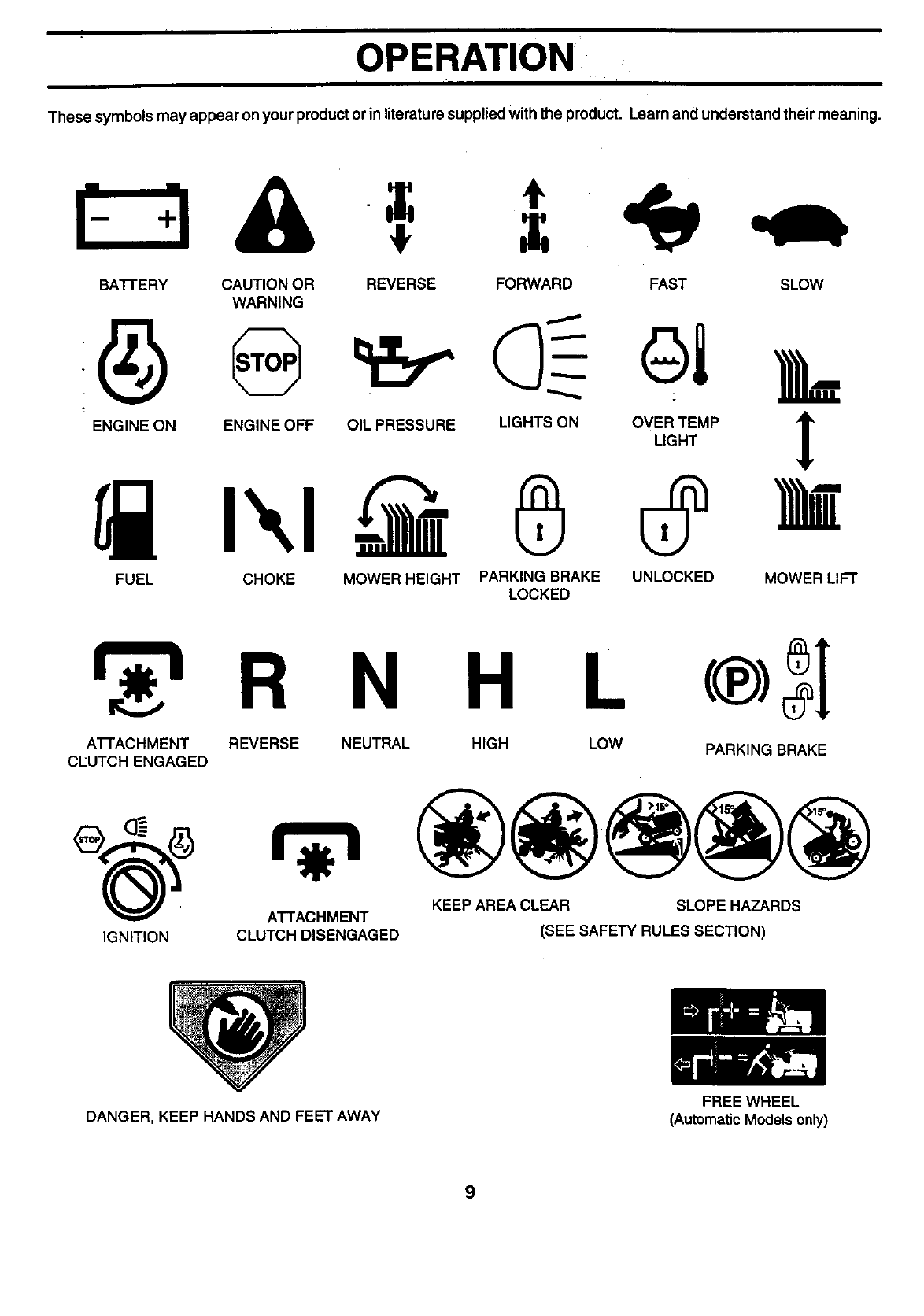
These symbols may appear on your produ_ or in literature supplied with the produ_, Leam and understand their meaning.
BATFERY CAUTION OR REVERSE FORWARD FAST SLOW
WARNING
FUEL CHOKE MOWER HEIGHT PARKING BRAKE UNLOCKED MOWER LIFT
LOCKED
N H L
ATTACHMENT REVERSE
CLUTCH ENGAGED NEUTRAL HIGH LOW PARKING BRAKE
KEEP AREA CLEAR SLOPE HAZARDS
ATTACHMENT
IGNITION CLUTCH DISENGAGED (SEE SAFETY RULES SECTION)
DANGER, KEEP HANDS AND FEET AWAY FREE WHEEL
(AutomaticModels only)
9
OPERATION
I I I
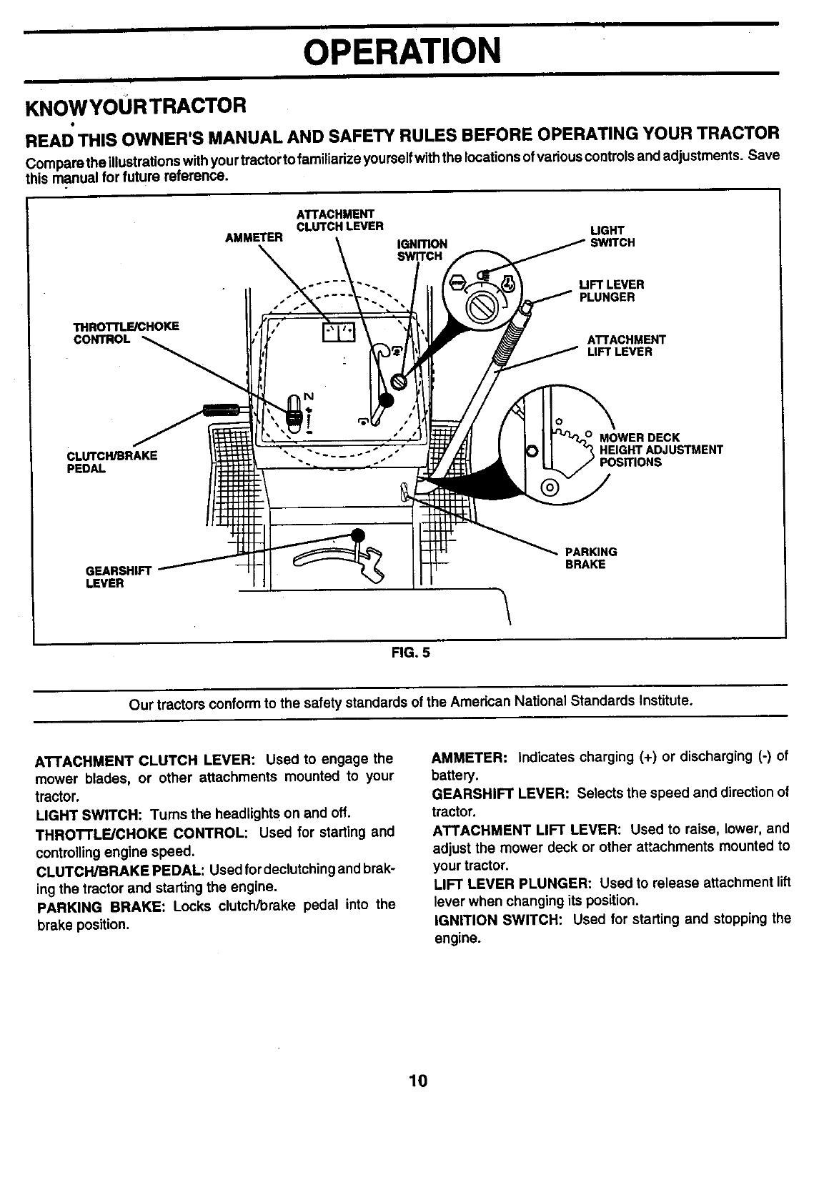
KNOWYOURTRACTOR
READ THIS OWNER'S MANUAL AND SAFETY RULES BEFORE OPERATING YOUR TRACTOR
Compare the illustrationswith you rtractor to familiarize yourselfwiththe locations ofvarious controls and adjustments. Save
this manual for future reference.
THROTFLE/CHOKE
CONTROL
ATTACHMENT
CLUTCH LEVER LIGHT
AMMETER IGNITION ;WITCH
SWITCH
UFT LEVER
PLUNGER
ATTACHMENT
LIFT LEVER
CLUTCH/BRAKE
PEDAL
HEIGHT ADJUSTMENT
GEARSHIFT
LEVER
PARKING
BRAKE
FIG. 5
Our tractors conform to the safety standards of the American National Standards Institute.
ATTACHMENT CLUTCH LEVER: Used to engage the
mower blades, or other attachments mounted to your
tractor.
LIGHT SWITCH: Turns the headlights on and off.
THROTTLE/CHOKE CONTROL: Used for starting and
controlling engine speed.
CLUTCH/BRAKE PEDAL: Used fordeclutching and brak-
ing the tractor and starting the engine.
PARKING BRAKE: Locks clutch/brake pedal into the
brake position.
AMMETER: Indicates charging (+) or discharging (-) of
battery.
GEARSHIFT LEVER: Selects the speed and direction of
tractor.
ATTACHMENT LIFT LEVER: Used to raise, lower, and
adjust the mower deck or other a_achments mounted to
your tractor.
LIFT LEVER PLUNGER: Used to release attachment lift
lever when changing its position.
IGNITION SWITCH: Used for starting and stopping the
engine.
10
OPERATION
The operation of any tractor can result In foreign objects thrown into the eyes, which
can result in severe eye damage. Always wear safety glasses or eye shields while
operating your tractor or performing any adjustments or repairs. We recommend awide
vision safety mask over spectacles or standard safety glasses.
HOW TO USE YOUR TRACTOR
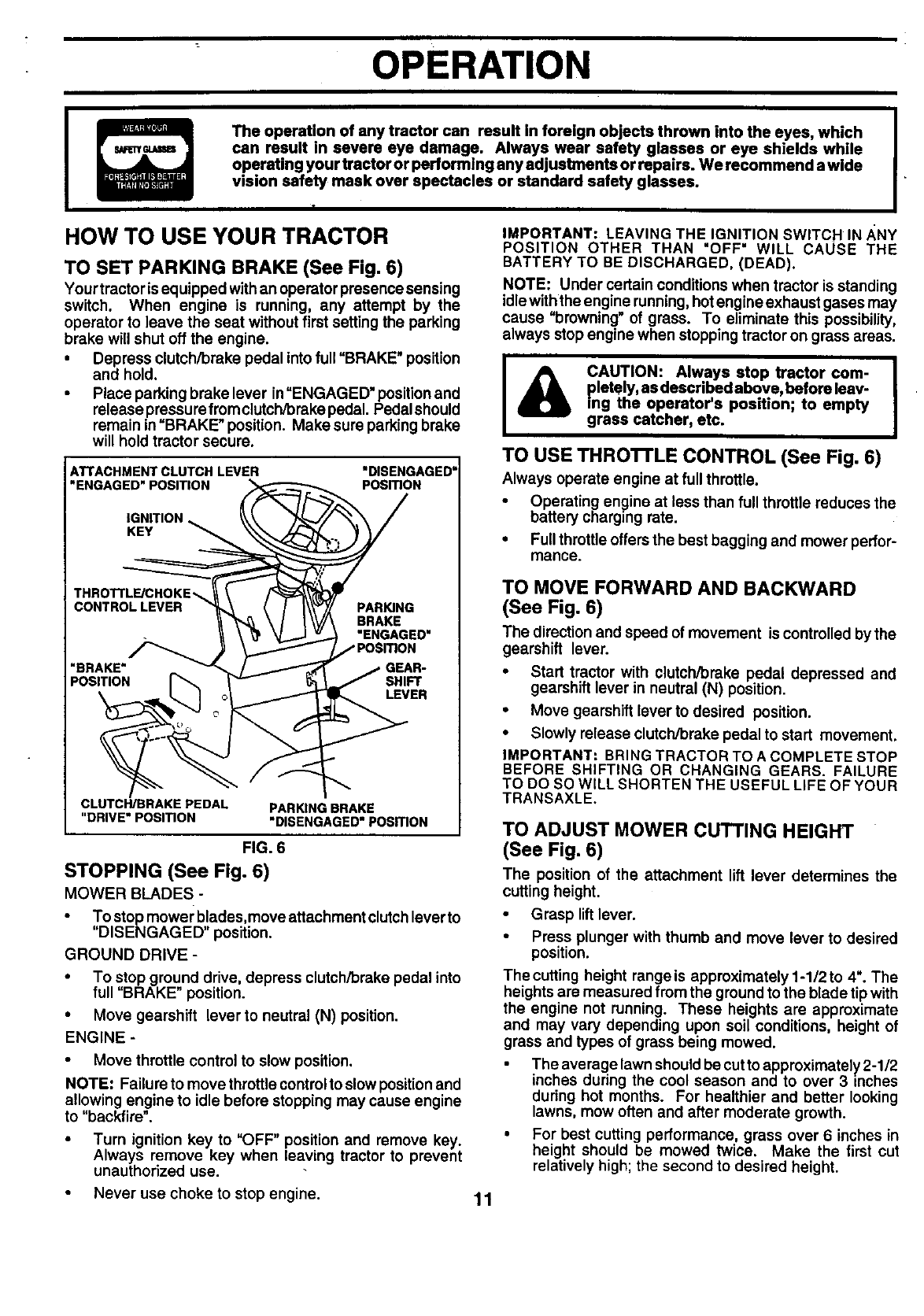
TO SET PARKING BRAKE (See Fig. 6)
Yourtractor is equipped withan operator presence sensing
switch. When engine is running, any attempt by the
operator to leave the seat without first setting the parking
brake will shut off the engine.
•Depress clutch/brake pedal into full "BRAKE" position
and hold.
•Place parking brake lever in"ENGAGED" positionand
release pressure fromclutch/brake pedal. Pedal should
remain in "BRAKE" position. Make sure parking brake
will hold tractor secure.
ATTACHMENT CLUTCH LEVER
"ENGAGED" POSITION "DISENGAGED"
PosmoN
IGNITION
KEY
THROTTLE/CHOKE,.,
CONTROL LEVER PARING
BRAKE
"ENGAGED"
"BRAKE" GEAR-
POSITION SHIFT
LEVER
CLUTCH/BRAKE PEDAL
"DRIVE"POSmON PARKING BRAKE
"DISENGAGED"POSmON
FIG. 6
STOPPING (See Fig. 6)
MOWER BLADES -
• To stop mower blades,move attachment clutchleverto
"DISENGAGED" position.
GROUND DRIVE -
• To stop ground drive, depress clutch/brake pedal into
full "BRAKE" position.
• Move gearshift lever to neutral (N) position.
ENGINE -
• Move throttle control to slow position.
NOTE: Failure to move throttle control to slow position and
allowing engine to idle before stopping may cause engine
to "backfire".
• Turn ignition key to "OFF" position and remove key.
Always remove key when leaving tractor to prevent
unauthorized use.
IMPORTANT: LEAVING THE IGNITION SWITCH IN/_NY
POSITION OTHER THAN "OFF" WILL CAUSE THE
BATTERY TO BE DISCHARGED, (DEAD).
NOTE: Under certain conditions when tractor is standing
idle withthe engine running, hotengine exhaust gases may
cause "browning" of grass. To eliminate this possibility,
always stop engine when stopping tractor on grass areas.
I& CAUTION: Always stop tractor com-
pletely, as descr bed above, before leav-
ing the operator's position; to empty
grass catcher, etc.
TO USE THRO'n'LE CONTROL (See Fig. 6)
Always operate engine at full throttle.
•Operating engine at less than full throttle reduces the
battery charging rate.
• Full throttle offersthe best bagging and mower perfor-
mance.
TO MOVE FORWARD AND BACKWARD
(See Fig. 6)
The directionand speed of movement is controlled bythe
gearshift lever.
•Start tractor with clutch/brake pedal depressed and
gearshift lever in neutral (N) position.
•Move gearshift lever to desired position.
•Slowly release clutch/brake pedal to start movement.
IMPORTANT: BRING TRACTOR TO A COMPLETE STOP
BEFORE SHIFTING OR CHANGING GEARS. FAILURE
TO DO SO WILL SHORTEN THE USEFUL LIFE OF YOUR
TRANSAXLE.
TO ADJUST MOWER CUTTING HEIGHT
(See Fig. 6)
The position of the attachment lift lever determines the
cutting height.
•Grasp lift lever.
•Press plunger with thumb and move lever to desired
position.
The cutting height range is approximately 1-1/2 to 4". The
heights are measured from the groundto the blade tip with
the engine not running. These heights are approximate
and may vary depending upon soil conditions, height of
grass and types of grass being mowed.
The average lawn should be cutto approximately 2-1/2
inches during the cool season and to over 3 inches
during hot months. For healthier and better looking
lawns, mow often and after moderate growth.
•For best cutting performance, grass over 6 inches in
height should be mowed twice. Make the first cut
relatively high; the second to desired height.
Never use choke to stop engine. 11
OPERATION
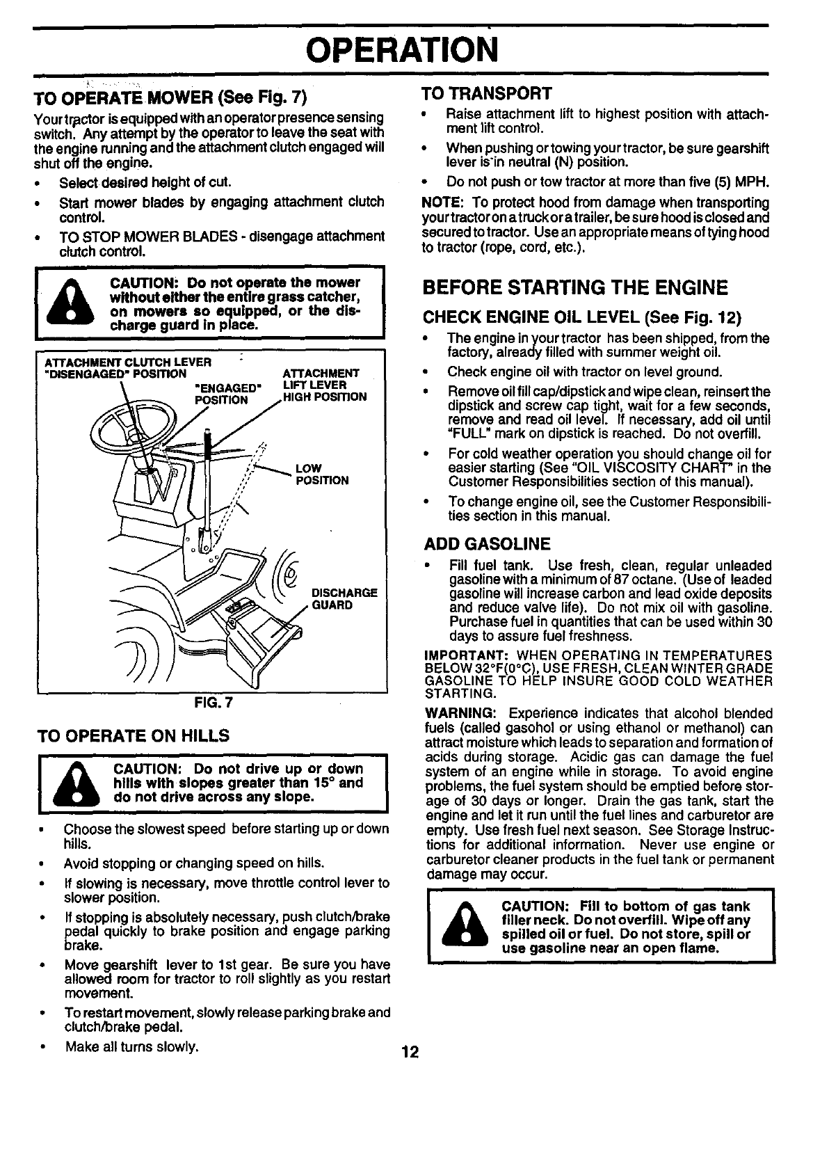
TO OPERATE MOWER (See Fig. 7) TO TRANSPORT
Your tractor isequipped with an operator presence sensing
switch. Any attempt by the operator to leave the seat with
the engine running and the attachment clutch engaged will
shut off the engine.
•Select desired height of cut.
•Start mower blades by engaging attachment clutch
control.
•TO STOP MOWER BLADES - disengage attachment
clutch control.
I& CAUTION: Do not operate the mower
without either the entire grass catcher,
on mowers so equipped, or the dis-
charge guard in place.
ATTACHMENT CLUTCHLEVER :
"_SENGAGED'POSmON
"ENGAGED"
POSITION
ATTACHMENT
LIFT LEVER
HIGH POSITION
DISCHARGE
FIG. 7
TO OPERATE ON HILLS
ICAUTION: Do not drive up or down
hills with slopes greater than 15° and
do not drive across any slope.
Choose the slowest speed before starting up or down
hills.
Avoid stopping or changing speed on hills.
If slowing is necessary, move throttle control lever to
slower position.
If stopping is absolutely necessary, push clutch/brake
pedal quickly to brake position and engage parking
brake.
Move gearshift lever to 1st gear. Be sure you have
allowed room for tractor to roll slightly as you restart
movement.
To restart movement, slowly release parking brake and
clutch/brake pedal.
•Raise attachment lift to highest position with attach-
ment tilt control.
•When pushing or towingyourtractor, be sure gearshift
lever isin neutral (N) position.
•Do not push or tow tractor at more than five (5) MPH.
NOTE: To protect hood from damage when transporting
your tractorona truckor atrailer, be sure hood isclosed and
secured totractor. Use an appropriate means of tying hood
to tractor (rope, cord, etc.).
BEFORE STARTING THE ENGINE
CHECK ENGINE OIL LEVEL (See Fig. 12)
• The engine inyour tractor has been shipped, from the
factory, already filled with summer weight oil.
•Check engine oil with tractor on level ground.
•Remove oilfill cap/dipstick and wipe clean, reinsertthe
dipstick and screw cap tight, wait for afew seconds,
remove and read oil level If necessary, add oil until
"FULL" mark on dipstick is reached. Do notoverfill.
•For cold weather operation you should change oil for
easier starting (See "OIL VISCOSITY CHART" in the
Customer Responsibilities section of this manual).
•To change engine oil, see the Customer Responsibili-
ties section in this manual.
ADD GASOLINE
•Fill fuel tank. Use fresh, clean, regular unleaded
gasoline with a minimum of 87 octane. (Use of leaded
gasoline will increase carbon and lead oxide deposits
and reduce valve life). Do not mix oil with gasoline.
Purchase fuel in quantities that can be used within 30
days to assure fuel freshness.
IMPORTANT: WHEN OPERATING IN TEMPERATURES
BELOW 32°F(0°C), USE FRESH, CLEAN WINTER GRADE
GASOLINE TO HELP INSURE GOOD COLD WEATHER
STARTING.
WARNING: Experience indicates that alcohol blended
fuels (called gasohol or using ethanol or methanol) can
attract moisturewhich leads to separation and formation of
acids during storage. Acidic gas can damage the fuel
system of an engine while in storage. To avoid engine
problems, the fuel system should be emptied before stor-
age of 30 days or longer. Drain the gas tank, start the
engine and let it run untilthe fuel lines and carburetor are
empty. Use fresh fuel next season. See Storage Instruc-
tions for additional information. Never use engine or
carburetor cleaner products in the fuel tank or permanent
damage may occur.
I & CAUTION: Fill to bottom of gas tank I
I
filler neck. Do not overfill. Wipe off any I
spilled oil or fuel. Do not store, spill or
use gasoline near an open flame.
•Make all turns slowly. 12
ill i
OPERATION
TO START ENGINE (See Fig. 6)
When starting the engine for the first time or if the engine
has run out of fuel, it will take extra cranking time to move
fuel from the tank to the engine.
•Sit on seat in operating position, depress clutch/brake
pedal and set parking brake.
•Place gear shift lever in neutral (N) position.
• Move attachment clutch to =DISENGAGED" position.
•Move throttle control to choke position.
NOTE: Before starting, read the warm and cold starting
procedures below.
•Insert keyintoignitionandturn keyclockwiseto "START"
position and release key as soon as engine starts. Do
not run starter continuously for more than fifteen sec-
onds per minute. If the engine does not start after
several attempts, move throttlecontrol to fast position,
wait afew minutes and try again. If engine still does not
start, move the throttle control back to the choke
position and retry.
WARM WEATHER STARTING (50° F and above)
•When engine starts, move the throttlecontroltothe fast
position.
•The attachments and ground ddve can now be used. If
the engine does notaccept the load, restartthe engine
and allow itto warm up for one minute usingthe choke
as described above,
COLD WEATHER STARTING (50° F and below)
• When engine starts, allowengineto runwiththe throttle
control in the choke position until the engine runs
roughly,then move throttle controlto fast position. This
may require an engine warm-up period from several
seconds to several minutes, depending on the tem-
perature.
•The attachments can also be used during the engine
warm-up period.
NOTE: If at a high altitude (above 3000 feet) or in cold
temperatures (below 32 F) the carburetor fuel mixture may
need to be adjusted for best engine performance. See "TO
ADJUST CARBURETOR" in the Service and Adjustments
section of this manual.
MOWING TIPS
•Tire chains cannot be used when the mower housing
is attached to tractor.
•Mower should be properly leveled for best mowing
performance. See "TO LEVEL MOWER HOUSING" in
the Service and Adjustments section of this manual.
•The left hand side of mower should be used for trim-
ming.
•Drive so that clippings are discharged onto the area
that has been cut. Have the cut area to the rightof the
machine. This will result in amore even distributionof
clippings and more uniform cutting.
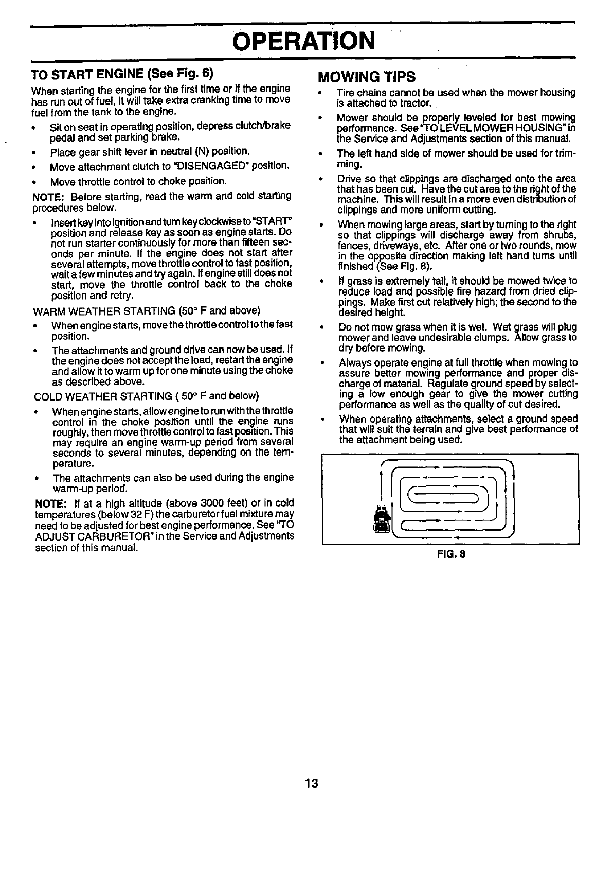
•When mowing large areas, start by turning to the dght
so that clippings will discharge away from shrubs
fences, driveways, etc. After one ortwo rounds, mow
in the opposite direction making left hand turns until
finished (See Fig. 8).
•If grass is extremely tall, it should be mowed twice to
reduce load and possible fire hazard from dried clip-
pings. Make first cut relatively high; the second to the
desired height.
•Do not mow grass when it is wet. Wet grass will plug
mower and leave undesirable clumps. Allow grass to
dry before mowing.
•Always operate engine at full throttle when mowing to
assure better mowing performance and proper dis-
charge of material. Regulate ground speed by select-
ing a low enough gear to give the mower cutting
performance as well as the quality of cut desired.
•When operating attachments, select a ground speed
that will suit the terrain and give best performance of
the attachment being used.
FIG. 8
13
cuSTOMER RESPONSIBILITIES
FILL IN DATESsERVICE _._f_:
AS YOU COMPLETE ._j.__j_._-._._..___-_'_4,_._'4. '_-_"/.._c_._'_ -
Check Brake Operation _1
IBm
Check Tire Pressure
Check Operator Presence and
T Interlock Systems
Check for Loose Fasteners I_:, I_
A Sharpen/Replace Mower Blades i4
Lubrication Chart l# #
T Check Battery Level
RClean Battery and Terminals V'
Check Transaxle Cooling
Adjust Blade Belt(s) Tension I_s
Adjust Motion Drive Belt(s) Tension V's
Check Engine Oil Level I_
Change Engine Oil _1.2,3
E Clean Air Filter _:
Clean Air Screen
G Inspect Muffler/Spark Arrester li_
NI Oil Rlter (if Ik#_1,2
Replace equipped)
E clean Engine Cooling Fins V'=
Replace Spark Plug I_ I_
Replace Air Filter Paper Cartddge
Replace Fuel Filter I_
1 - Change more often when operating under a heavy load or in high ambient temperatures.
2 o Service more often when operating in dirty or dusty conditions.
3 - If equipped with oil filter, change oil every 50 hours.
4 - Replace blades more often when mowing in sandy soil.
GENERAL RECOMMENDATIONS
The warranty on thistractor does not cover items that have
been subjected to operator abuse or negligence. To
receive full value from the warranty, operator must main-
tain tractor as instructed in this manual.
Some adjustments will need to be made periodically to
properly maintain your tractor.
All adjustments in the Service and Adjustments section of
this manual should be checked at least once each season.
®
5 - If equipped with adjustable system.
6 - Not required if equipped with maintenance-f ree battery.
7-Tighten front axle pivot bolt to 35 ft.-los, maximum.
Do not overtighten.
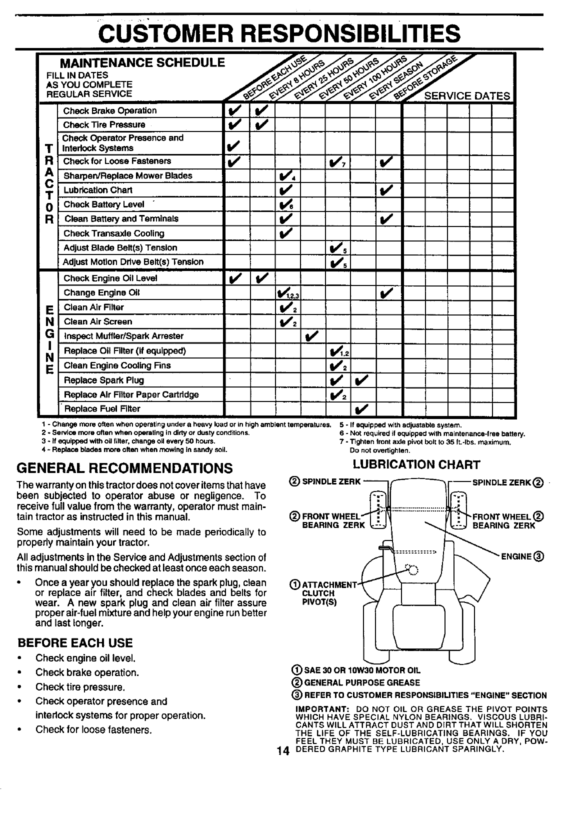
LUBRICATION CHART
@BEARING ZERK
Once a year you should replace the spark plug, clean (_
or replace air filter, and check blades and belts for CLUTCH
wear. A new spark plug and clean air filter assure PIVOT(S)
proper air-fuel mixture and help your engine runbetter
and last longer,
.
"FRONT WHEEL ®
BEARING ZERK
®
BEFORE EACH USE
•Check engine oil level.
•Check brake operation.
•Check tire pressure.
•Check operator presence and
interlock systems for proper operation.
•Check for loose fasteners.
®SAE 30 OR 10W30 MOTOR OIL
®GENERAL PURPOSE GREASE
®REFER TO CUSTOMER RESPONSIBILITIES "ENGINE" SECTION
IMPORTANT: DO NOT OIL OR GREASE THE PIVOT POINTS
WHICH HAVE SPECIAL NYLON BEARINGS. VISCOUS LUBRI-
CANTS WILL ATTRACT DUST AND DIRT THAT WILL SHORTEN
THE LIFE OF THE SELF-LUBRICATING BEARINGS. IF YOU
FEEL THEY MUST BE LUBRICATED, USE ONLY A DRY, POW-
14 DERED GRAPHITE TYPE LUBRICANT SPARINGLY.
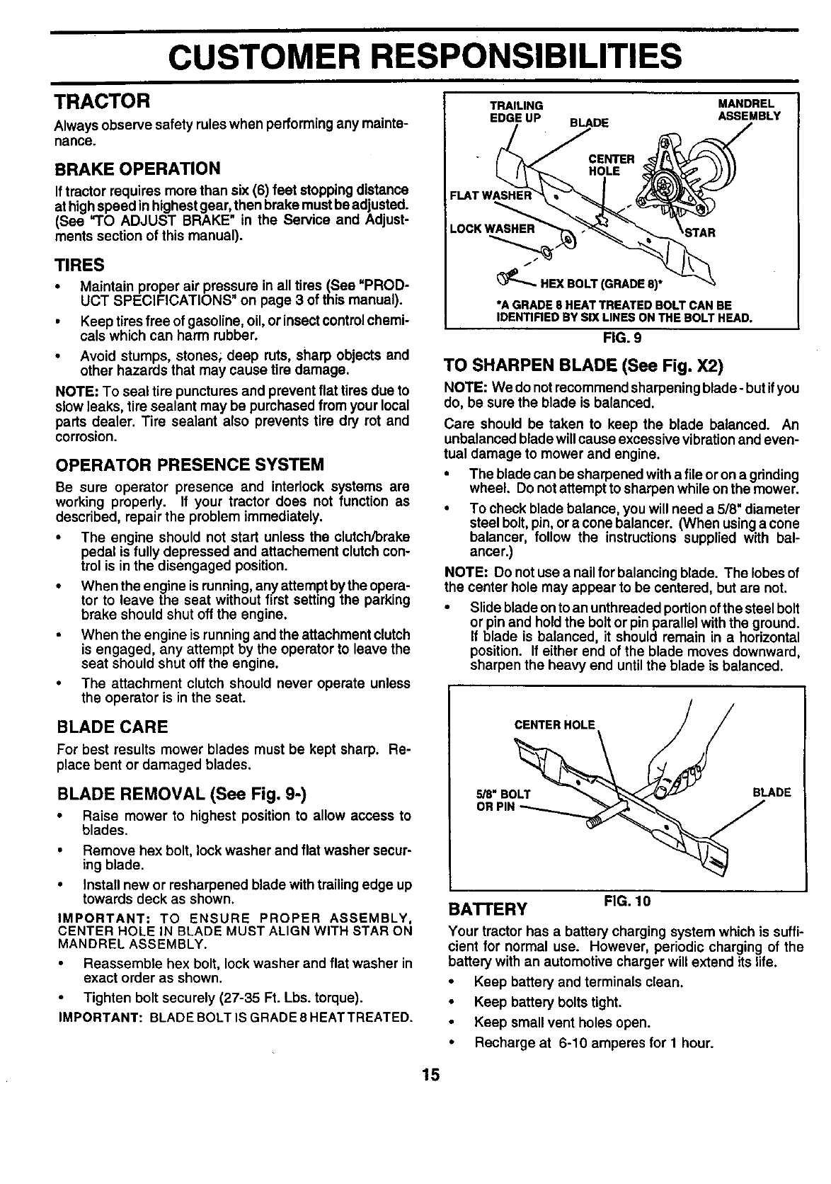
CUSTOMER RESPONSIBILITIES
TRAILING MANDREL
EDGE UP ASSEMBLY
TRACTOR
Always observe safety rules when performing any mainte-
nance.
BRAKE OPERATION
If tractor requires more than six (6) feet stopping distance
at highspeed in highest gear, then brake must be adjusted.
(See "TO ADJUST BRAKE" in the Service and Adjust-
ments section of this manual).
TIRES
•Maintain proper air pressure in all tires (See =PROD-
UCT SPECIFICATIONS" on page 3 of this manual).
• Keep tiresfree of gasoline, oil, or insectcontrol chemi-
cals which can harm rubber.
• Avoid stumps, stones; deep ruts, sharp objects and
other hazards that may cause tire damage.
NOTE: To seal tire punctures and prevent flat tires due to
slow leaks, tire sealant may be purchased from your local
parts dealer. Tire sealant also prevents tire dry rot and
corrosion.
OPERATOR PRESENCE SYSTEM
Be sure operator presence and interlock systems are
working properly. If your tractor does not function as
described, repair the problem immediately.
•The engine should not start unless the clutch/brake
pedal is fully depressed and attachement clutch con-
trol is in the disengaged position.
•When the engine is running, any attempt bythe opera-
tor to leave the seat without first setting the parking
brake should shut off the engine.
•When the engine is running and the attachment clutch
is engaged, any attempt by the operator to leave the
seat should shut off the engine.
•The attachment clutch should never operate unless
the operator is in the seat.
BLADE CARE
For best results mower blades must be kept sharp. Re-
place bent or damaged blades,
BLADE REMOVAL (See Fig. 9-)
•Raise mower to highest position to allow access to
blades.
• Remove hex bolt, lock washer and flat washer secur-
ing blade.
•Install new or resharpened blade with trailingedge up
towards deck as shown.
IMPORTANT: TO ENSURE PROPER ASSEMBLY,
CENTER HOLEIN BLADE MUSTALIGN WITH STAR ON
MANDRELASSEMBLY.
Reassemble hex bolt, lock washer and flat washer in
exact order as shown.
•Tighten bolt securely (27-35 Ft. Lbs. torque).
IMPORTANT: BLADE BOLT IS GRADE 8 HEAT TREATED.
BLADE
FLAT WASHER
LOCK WASHER
HEX BOLT (GRADE 8)*
STAR
*A GRADES HEAT TREATED BOLT CAN BE
IDENTIRED BY SIX LINES ON THE BOLT HEAD.
FIG. 9
TO SHARPEN BLADE (See Fig. X2)
NOTE: We donotrecommendsharpeningblade-butifyou
do, be surethe bladeis balanced.
Care should be taken to keep the blade balanced. An
unbalanced blade will cause excessive vibration and even-
tual damage to mower and engine.
• The blade can be sharpened with a file or on a gdnding
wheel. Do not attempt to sharpen while on the mower.
• To check blade balance, you will need a 5/8" diameter
steel bolt, pin, or a cone balancer. (When using a cone
balancer, follow the instructions supplied with bal-
ancer.)
NOTE: Do not use a nail for balancing blade. The lobes of
the center hole may appear to be centered, but are not.
• Slide blade on to an unthreaded portion of the steel bolt
or pin and hold the bolt or pin parallel with the ground.
If blade is balanced, it should remain in a horizontal
position. If either end of the blade moves downward,
sharpen the heavy end until the blade is balanced.
CENTER HOLE _// /
5/8" BO_ BLADE
OR PIN
BATTERY FIG. 10
Your tractor has a battery charging system which is suffi-
cient for normal use. However, periodic charging of the
battery with an automotive charger will extend its life.
•Keep battery and terminals clean.
•Keep battery bolts tight.
Keep small vent holes open.
•Recharge at 6-10 amperes for 1 hour.
15
CUSTOMER RESPONSIBILITIES
TO CLEAN BA'I-rERY AND TERMINALS
Corrosion and dirt onthe battery and terminals can cause the
battery to "leak" power.
•Open battery box door.
•DisconnectBLACKbatterycablefirst thenRED battery
cable and remove battery from tractor.
• Rinse the battery with plain water and dry.
•Clean terminals and battery cable ends with wire brush
until bdght.
•Coat terminals with grease or petroleum jelly.
•Reinstall battery (See "CONNECT BATTERY" in the
Assembly section of this manual).
V-BELTS
Check V-belts for deterioration and wear after 100 hoursof
operation and replace if necessary. The belts are not
adjustable. Replace belts if they begin to slip from wear.
TRANSAXLE COOLING
Keep transaxle free from build-up of dirt and chaff which
can restrict cooling.
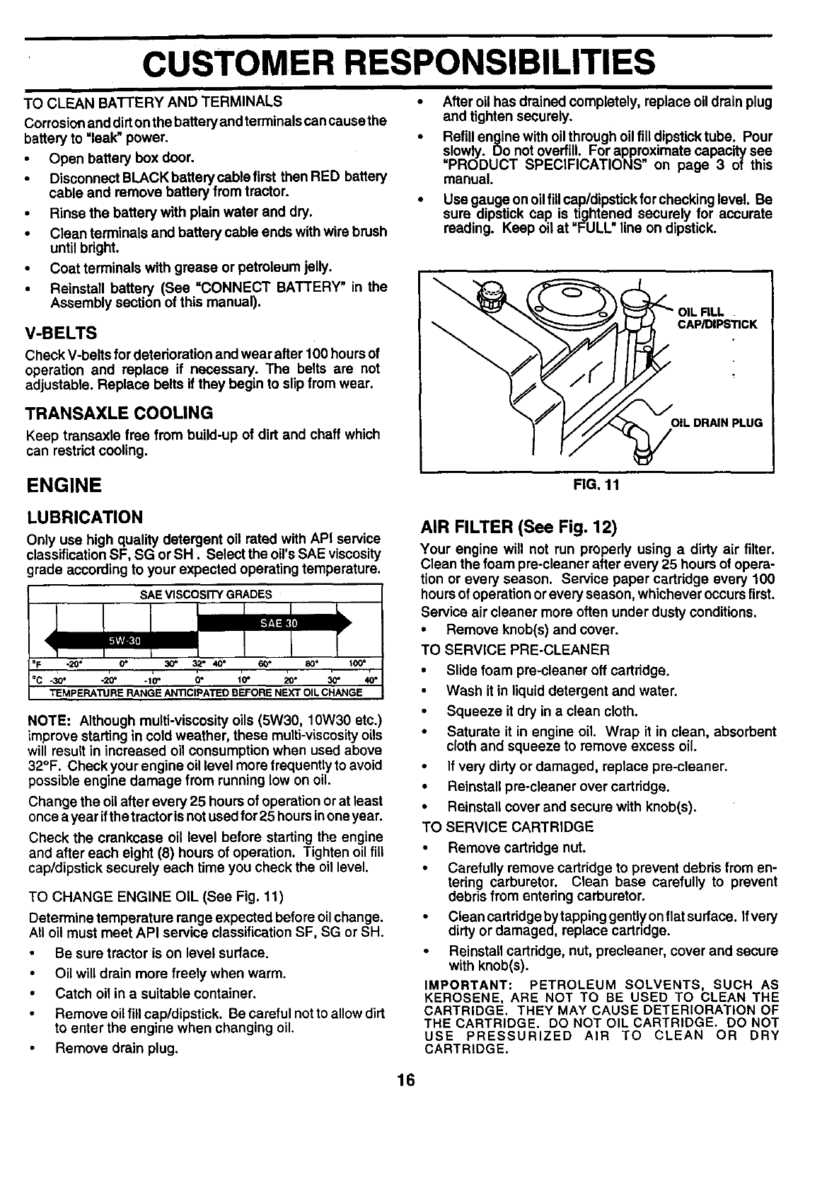
After oil has drained completely, replace oil drain plug
and tighten securely.
Refill engine with oil through oil fill dipsticktube. Pour
slowly. Do not overfill. For approximate capacity see
=PRODUCT SPECIFICATIONS" on page 3 of this
manual.
Use gauge on oil fillcap/dipstick forchecking level. Be
sure dipstick cap is tightened securely for accurate
reading. Keep oil at "FULL line on dipstick.
CAP/DIPS_CK
OIL DRAIN PLUG
ENGINE FIG. 11
LUBRICATION
Only use high quality detergent oil rated with API service
classification SF, SG or SH. Select the oil'sSAE viscosity
grade according to your expected operating temperature.
SAE VISCOSITY GRADES
-20° 0" 30" 3,_" 40° 60*
-so. -_" .1_" a" ;o- 20. _"
TEMPERATURE RANGE AN'nCIPATEO BEFORE NEXT OIL CHANGE
NOTE: Although multi-viscosity oils (5W30, 10W30 etc.)
improve starting in cold weather, these mulU-viscosity oils
will result in increased oil consumption when used above
32°F. Check your engine oil level more frequently to avoid
possible engine damage from running low on oil.
Change the oil after every 25 hours of operation or at least
once a year ifthe tractor isnot usedfor 25 hoursinoneyear.
Check the crankcase oil level before starting the engine
and after each eight (8) hours of operation. Tighten oil fill
cap/dipstick securely each time you check the oil level.
TO CHANGE ENGINE OIL (See Fig. 11)
Determine temperature range expected before oil change.
All oil must meet API service classification SF, SG or SH.
Be sure tractor is on level surface.
• Oil will drain more freely when warm.
Catch oil in a suitable container.
• Remove oil fill cap/dipstick. Be careful not to allow dirt
to enter the engine when changing oil.
Remove drain plug.
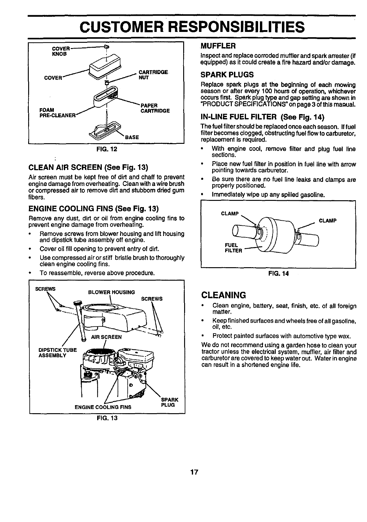
AIR FILTER (See Fig. 12)
Your engine will not run properly using a dirty air filter.
Clean the foam pre-cleaner after every 25 hours of opera-
tion or every season. Service paper cartridge every 100
hours of operation or every season, whichever occurs first.
Service air cleaner more often under dusty conditions.
•Remove knob(s) and cover.
TO SERVICE PRE-CLEANER
•Slide foam pre-cleener off cartridge.
•Wash it in liquiddetergent and water.
•Squeeze it dry in a clean cloth.
•Saturate it in engine oil. Wrap it in clean, absorbent
cloth and squeeze to remove excess oil.
If very dirty or damaged, replace pre-cleaner.
•Reinstall pre-cleaner over cartridge.
•Reinstall cover and secure with knob(s).
TO SERVICE CARTRIDGE
•Remove cartridge nut.
•Carefully remove cartridge to prevent debds from en-
tering carburetor. Clean base carefully to prevent
debris from entering carburetor.
•CleancartridgebytappinggenUyonflatsurface. Ifvery
dirty or damaged, replace cartndge.
•Reinstall cartridge, nut, precleaner, cover and secure
with knob(s).
IMPORTANT: PETROLEUM SOLVENTS, SUCH AS
KEROSENE, ARE NOT TO BE USED TO CLEAN THE
CARTRIDGE. THEY MAY CAUSE DETERIORATION OF
THE CARTRIDGE. DO NOT OIL CARTRIDGE. DO NOT
USE PRESSURIZED AIR TO CLEAN OR DRY
CARTRIDGE.
16
CUSTOMERRESPONSIBILITIES
COVER-
KNOB
CARTRIDGE
FOAM ' PAPER
_BASE CARTRIDGE
FIG. 12
CLEAN AIR SCREEN (See Fig, 13)
Air screen must be kept free of dirt and chaff to prevent
engine damage from overheating. Clean witha wire brush
or compressed air to remove dirt and stubborn dried gum
fibers.
ENGINE COOLING FINS (See Fig. 13)
Remove any dust, dirt or oil from engine cooling fins to
prevent engine damage from overheating.
• Remove screws from blower housing and lift housing
and dipstick tube assembly off engine.
• Cover oil fill opening to prevent entry of dirt.
•Use compressed air or stiff bristle brush tothoroughly
clean engine cooling fins.
• To reassemble, reverse above procedure.
MUFFLER
Inspect andreplacecorrodedmuffler andsparkarrester (if
equipped)as itcouldcreatea fire hazardand/ordamage.
SPARKPLUGS
Replace spark plugs at the beginning of each mowing
season or after every 100 hours of operation, whichever
occurs first. Spark plug type and gap setting are shown in
"PRODUCT SPECIFICATIONS" on page 3 of this manual
IN-LINE FUEL FILTER (See Fig. 14)
The fuel filter should be replaced once each season. If fuel
filter becomes clogged, obstructingfuel flow to carburetor,
replacement is required.
•With engine cool, remove filter and plug fuel line
sections.
• Place new fuel filter in position in fuel line with arrow
pointing towards carburetor.
•Be sure there are no fuel line leaks and clamps are
properly positioned.
•Immediately wipe up any spilled gasoline.
CLAMP
FU_ CLAMP
FILTER --
FIG. 14
SCREWS
\SLOWER HOUSING
SCREWS
DIPSTICK TUBE
ASSEMBLY
ENGINE COOLING RNS
SPARK
PLUG
FIG. 13
CLEANING
• Clean engine, battery, seat, finish, etc. of all foreign
matter.
•Keep finished surfaces and wheels free of all gasoline,
oil, etc.
Protect painted surfaces with automotive type wax.
We do not recommend using a garden hose to clean your
tractor unless the electrical system, muffler, air filter and
carburetor are covered to keep water out. Water in engine
can result in a shortened engine life.
17
&
I
SERVICE AND ADJUSTMENTS
CAUTION: BEFORE PERFORMING ANY SERVICE OR ADJUSTMENTS:
Depress clutch/brake pedal fully and set parking brake.
Place gearshift lever In neutral (N) position.
• Place attachment clutch In "DISENGAGED" position.
•Tum ignition key "OFF" and remove key.
•Make sure the blades and all moving parts have completely stopped.
•Disconnect spark plug wire from spark plug and piece wire where it cannot come in contact with
plug.
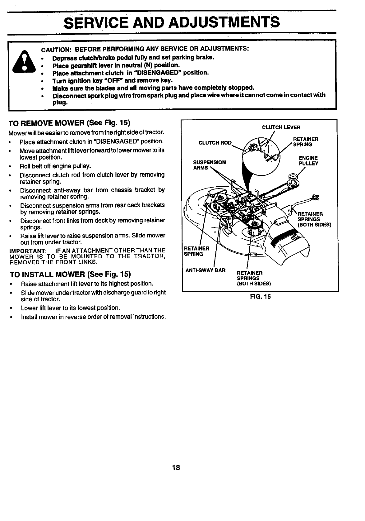
TO REMOVE MOWER (See Fig. 15)
MowerwUl be easier to remove fromthe right sideof tractor.
•Place attachment clutch in =DISENGAGED" position.
•Move attachment liftlever forwardto lower mower to its
lowest position.
•Roll belt off engine pulley.
•Disconnect clutch rod from clutch lever by removing
retainer spring.
•Disconnect anti-sway, bar from chassis bracket by
removing retainer spnng.
•Disconnect suspension arms from rear deck brackets
by removing retainer spdngs.
Disconnect front links from deck by removing retainer
springs,
•Raise lift lever to raise suspension arms. Slide mower
out from under tractor,
IMPORTANT: IF AN ATTACHMENT OTHER THAN THE
MOWER IS TO BE MOUNTED TO THE TRACTOR,
REMOVED THE FRONT LINKS.
TO INSTALL MOWER (See Fig. 15)
Raise attachment lift lever to its highest position.
•Slide mower under tractor withdischarge guard to dght
side of tractor.
•Lower lift lever to its lowest position.
Install mower in reverse order of removal instructions.
CLUTCHROD
SUSPENSION
ARMS
ANTI-SWAY BAR
CLUTCH LEVER
RETAINER
ENGINE
PULLEY
SPRINGS
RETAINER
SPRINGS
(BOTH SIDES)
FIG. 15
18
SERVICE AND ADJUSTMENTS
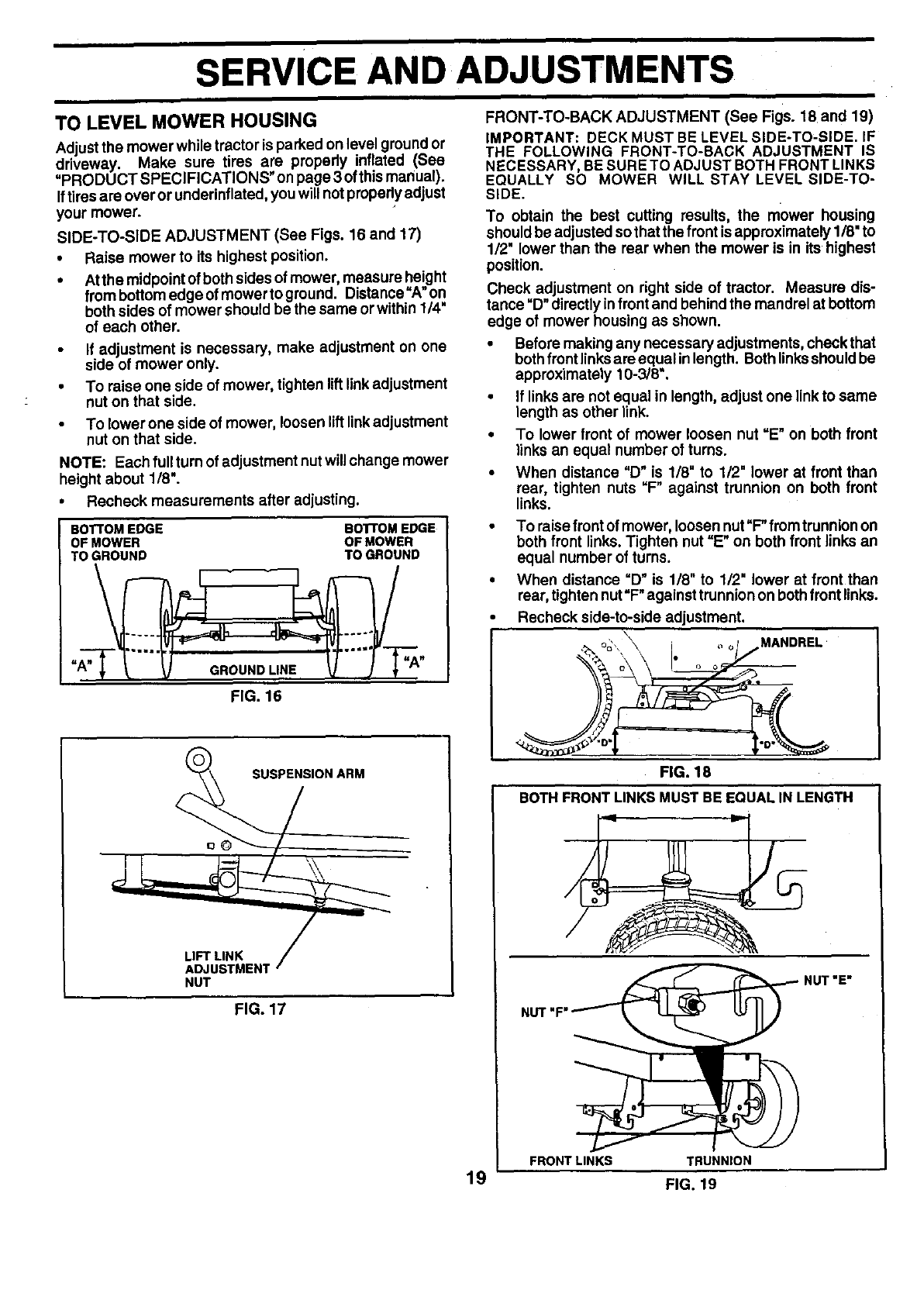
TO LEVEL MOWER HOUSING
Adjustthe mower while tractor is parked on level ground or
driveway. Make sure tires are propedy inflated (See
=PRODUCT SPECIFICATIONS" on page 3 ofthismanual).
Iftires are over or underinflated, you will not propedy adjust
your mower.
SIDE-TO-SIDE ADJUSTMENT (See Figs. 16 and 17)
•Raise mower to its highest position.
•At the midpoint of both sides of mower, measure height
frem bottom edge of mower to ground. Distance =A"on
both sides of mower should be the same or within 1/4"
of each other.
If adjustment is necessary, make adjustment on one
side of mower only.
•To raise one side of mower, tighten lift link adjustment
nut on that side.
•To lower one side of mower, loosen liftlinkadjustment
nut on that side.
NOTE: Each full turn of adjustment nutwill change mower
height about 1/8".
•Recheck measurements after adjusting.
BOTTOM EDGE
OF MOWER
TO GROUND
=E.
BOTTOM EDGE
OF MOWER
TO GROUND
FIG. 16
FRONT-TO-BACK ADJUSTMENT (See Figs. 18 and 19)
IMPORTANT: DECK MUST BE LEVEL SIDE-TO-SIDE. IF
THE FOLLOWING FRONT-TO-BACK ADJUSTMENT IS
NECESSARY, BE SURE TO ADJUST BOTH FRONT LINKS
EQUALLY SO MOWER WILL STAY LEVEL SIDE-TO-
SIDE.
To obtain the best cutting results, the mower housing
should be adjusted sothat the front isapproximately 1/8" to
1/2" lower than the rear when the mower is in its highest
position.
Check adjustment on right side of tractor. Measure dis-
tance "D"directly infront and behind the mandrel at bottom
edge of mower housing as shown.
•Before making any necessary adjustments, check that
bothfront linksare equal in length. Both linksshould be
apprOximately 10-3/8".
•If links are not equal in length, adjust one link to same
length as other link.
•To lower front of mower loosen nut =E" on both front
links an equal number of turns.
•When distance =D" is 1/8" to 1/2= lower at front than
rear, tighten nuts "F" against trunnion on both front
links.
• To raisefront of mower, loosen nut"F" fromtrunnion on
both front links. Tighten nut =E" on both front links an
equal number of turns.
•When distance =D" is 118"to 112"lower at front than
rear, tighten nut=F"against trunnion on both front links.
Recheck side-to-side adjustment.
MANDREL
SUSPENSION ARM
LIFT LINK
ADJUSTMEN1
NUT
FIG. 17
FIG. 18
BOTH FRONT LINKS MUST BE EQUAL IN LENGTH
FRONT LINKS TRUNNION
NUT "E"
19 FIG. 19
SERVICE AND ADJUSTMENTS
WITH PARKING BRAKE "ENGAGED"
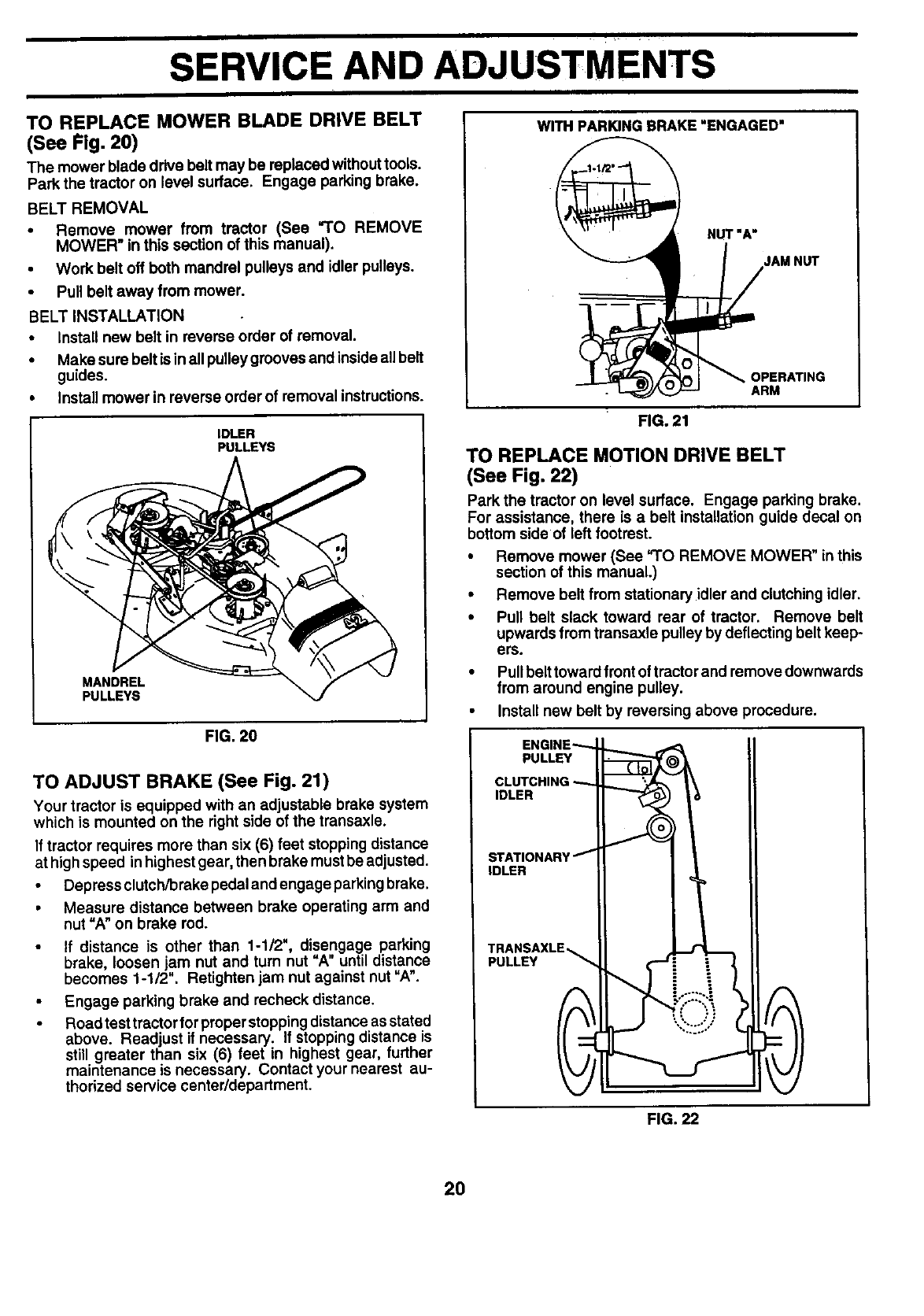
TO REPLACE MOWER BLADE DRIVE BELT
(See Fig. 20)
The mower blade drive belt may be replaced without tools.
Park the tractor on level surface. Engage parking brake.
BELT REMOVAL
•Remove mower from tractor (See =TO REMOVE
MOWER" in this section of this manual).
•Work belt off both mandrel pulleys and idler pulleys.
•Pull belt away from mower.
BELT INSTALLATION
•Install new belt in reverse order of removal.
•Make sure belt is inall pulley grooves and insideall belt
guides.
•Install mower in reverse order of removal instructions.
IDLER
PULLEYS
MANDREL
PULLEYS
FIG. 20
TO ADJUST BRAKE (See Fig. 21)
Your tractor is equipped with an adjustable brake system
which is mounted on the right side of the transaxle.
If tractor requires more than six (6) feet stoppingdistance
at highspeed in highest gear, then brake must be adjusted.
•Depress clutch/brake pedal and engage parkingbrake.
• Measure distance between brake operating arm and
nut "A" on brake rod.
• If distance is other than 1-1/2", disengage parking
brake, loosen jam nut and turn nut "A" until distance
becomes 1-1/2". Retighten jam nut against nut "A".
Engage parking brake and recheck distance.
Road test tractor for proper stoppingdistance as stated
above. Readjust if necessary. If stopping distance is
still greater than six (6) feet in highest gear, further
maintenance is necessary. Contact your nearest au-
thorized service center/department.
NUT "A"
JAMNUT
OPERATING
ARM
FIG. 21
TO REPLACE MOTION DRIVE BELT
(See Fig. 22)
Park the tractor on level surface. Engage parking brake.
For assistance, there is a belt installation guide decal on
bottom side of left footrest.
• Remove mower (See =TO REMOVE MOWER" in this
section of this manual.)
•Remove belt from stationary idler and clutching idler.
•Pull belt slack toward rear of tractor. Remove belt
upwards from transaxle pulley by deflecting belt keep-
ers.
•Pull belt toward front of tractor and remove downwards
from around engine pulley.
• Install new belt by reversing above procedure.
ENGINE'---
PULLEY
CLUTCHING
IDLER
STATIONARY I
IDLER
TRANSAXLE_
PULLEY "_
IFIG. 22
2O
SERVICE AND ADJUSTMENTS
TO ADJUST STEERING WHEEL ALIGNMENT
If steering wheel crossbars are not horizontal (left to right)
when wheels are positioned straightforward, removesteer-
ingwheel and reassemble per instructionsinthe Assembly
section of this manual,
FRONT WHEEL TOE-IN/CAMBER
The front wheel toe-in and camber are not adjustable on
your tractor. If damage has occurred to affect the front
wheel toe-in or camber, contact your nearest authorized
service center/department.
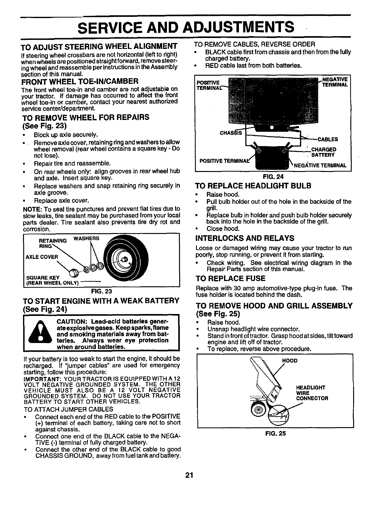
TO REMOVE WHEEL FOR REPAIRS
(See Fig. 23)
Block up axle securely.
•Remove axle cover, retaining ringand washers to allow
wheel removal (rear wheel contains asquare key - Do
not lose).
•Repair tire and reassemble.
•On rear wheels only: align grooves in rear wheel hub
and axle. Insert square key.
•Replace washers and snap retaining ring securely in
axle groove.
•Replace axle cover.
NOTE: To seal tire punctures and prevent flat tires due to
slow leaks, tire sealant may be purchased from your local
parts dealer. Tire sealant also prevents tire dry rot and
corrosion.
RETAINING WASHERS
I
SQUARE KEY_"_l"_"
[REAR WHEEL ONLY)
FIG. 23
TO START ENGINE WITH A WEAK BA'B'ERY
(See Fig. 24)
ate explosive gases. Keep sparks, flame
and smoking materials away from bat-
teries. Always wear eye protection
when around batteries.
If your battery is too weak to start the engine, it should be
recharged, if "jumper cables" are used for emergency
starting, follow this procedure:
IMPORTANT: YOU R TRACTOR IS EQUIPPED WITH A 12
VOLT NEGATIVE GROUNDED SYSTEM. THE OTHER
VEHICLE MUST ALSO BE A 12 VOLT NEGATIVE
GROUNDED SYSTEM. DO NOT USEYOURTRACTOR
BATTERY TO START OTHER VEHICLES.
TO A'I-I-ACH JUMPER CABLES
Connect each end of the RED cable to the POSITIVE
(+) terminal of each battery, taking care not to short
against chassis.
•Connect one end of the BLACK cable to the NEGA-
TIVE (-) terminal of fully charged battery.
Connect the other end of the BLACK cable to good
CHASSIS GROUND, away from fuel tank and battery.
TO REMOVE CABLES, REVERSE ORDER
•BLACK cable first from chassis and then from the fully
charged battery.
•RED cable last from both batteries.
POSITIVE • BATrERY
\NEG_,TIVETERMINAL
FIG. 24
TO REPLACE HEADLIGHT BULB
•Raise hood.
•Pull bulb holder out of the hole in the backside of the
grill.
•Replace bulb in holder and push bulb holder securely
back into the hole in the backside of the grill.
•Close hood.
INTERLOCKS AND RELAYS
Loose or damaged wiring may cause your tractor to run
poorly, stop running, or prevent it from starting.
•Check wiring. See electrical wiring diagram in the
Repair Parts section of this manual.
TO REPLACE FUSE
Replace with 30 amp automotive-type plug-in fuse. The
fuse holder is located behind the dash.
TO REMOVE HOOD AND GRILLASSEMBLY
(See Fig. 25)
•Raise hood.
•Unsnap headlight wire connector.
•Stand infrent oftractor. Grasp hood at sides, tilttoward
engine and lift off of tractor.
To replace, reverse above procedure.
HOOD
HEADL,G.T
/L_ WIRE
_ _NNECTOR
FIG. 25
21
ii i i
SERVICE AND ADJUSTMENTS
I
ENGINE
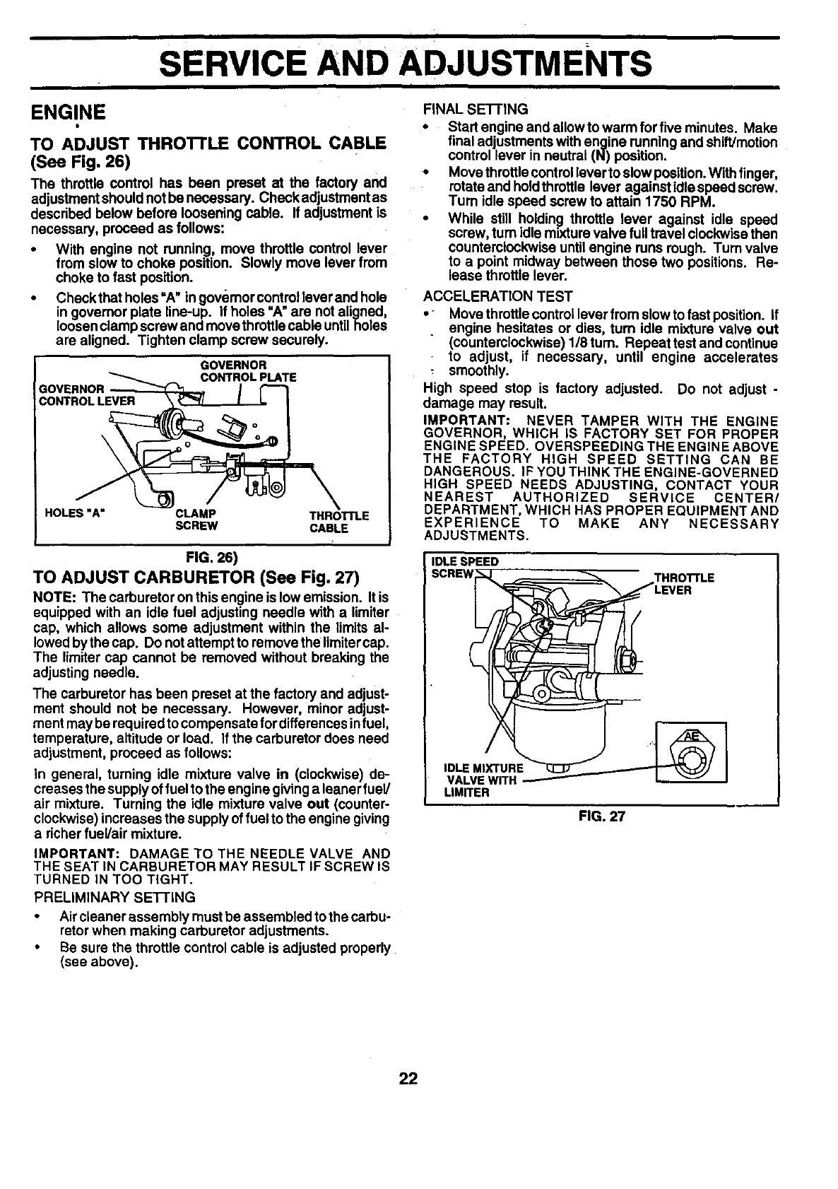
TO ADJUST THRO'n'LE CONTROL CABLE
(See Fig. 26)
The throttle control has been preset at the factory and
adjustment should not be necessary. Chock adjustment as
described below before loosening cable. If adjustment is
necessary, proceed as follows:
•With engine not running, move throttle control lever
from slow to choke position. Slowly move lever from
choke to fast position.
•Checkthatholes'A" lngovemorcontrolleverandhole
in governor plate line-up. If holes "A"are not aligned,
loosenclamp screw and move throttlecable untilholes
are aligned. Tighten clamp screw securely.
GOVERNOR
CONTROL PLATE
GOVERNOR
CONTROL LEVER
\
HOLES"A" CLAMP THROTTLE
SCREW CABLE
FIG. 26)
TO ADJUST CARBURETOR (See Fig. 27)
NOTE: The carburetor on this engine is lowemission. It is
equipped with an idle fuel adjusting needle with a limiter
cap, which allows some adjustment within the limits al-
lowed by the cap. Do notattempt to remove the limitercap.
The limiter cap cannot be removed without breaking the
adjusting needle.
The carburetor has been preset at the factory and adjust-
ment should not be necessary. However, minor adjust-
ment may be required to compensate fordifferences in fuel,
temperature, altitude or load. If the carburetor does need
adjustment, proceed as follows:
In general, turning idle mixture valve in (clockwise) de-
creases the supply of fuel to the engine giving a leaner fuel/
air mixture. Turning the idle mixture valve out (counter-
clockwise) increases the supply of fuel to the engine giving
a richer fuel/air mixture.
IMPORTANT: DAMAGE TO THE NEEDLE VALVE AND
THE SEAT IN CARBURETOR MAY RESULT IF SCREW IS
TURNED IN TOO TIGHT.
PRELIMINARY SETI'ING
Air cleaner assembly must be assembled to the carbu-
retor when making carburetor adjustments.
Be sure the throttle control cable is adjusted properly
(see above).
FINAL SE-I-FING
•Startengineandallowtowarmforfiveminutes. Make
final adjustments with engine running and shift/motion
control lever in neutral (N) position.
• Move throttle control lever to slowposition. With finger,
rotate and hold throttle lever against idle speed screw.
Turn idle speed screw to attain 1750 RPM.
• While still holding throttle lever against idle speed
screw, turn idle mixture valve full travel clockwise then
counterclockwise untilengine runs rough. Turn valve
to a point midway between those two positions. Re-
lease throttle lever.
ACCELERATION TEST
•Move throttle control lever from slow to fast position. If
engine hesitates or dies, turn idle mixture valve out
(counterclockwisa) l/Stum. Repeat test and continue
to adjust, if necessary, until engine accelerates
smoothly.
High speed stop is factory adjusted. Do not adjust -
damage may result.
IMPORTANT: NEVER TAMPER WITH THE ENGINE
GOVERNOR, WHICH IS FACTORY SET FOR PROPER
ENGINE SPEED. OVERSPEEDING THE ENGINE ABOVE
THE FACTORY HIGH SPEED SETTING CAN BE
DANGEROUS. IF YOU THINK THE ENGINE-GOVERNED
HIGH SPEED NEEDS ADJUSTING, CONTACT YOUR
NEAREST AUTHORIZED SERVICE CENTER/
DEPARTMENT, WHICH HAS PROPER EQUIPMENT AND
EXPERIENCE TO MAKE ANY NECESSARY
ADJUSTMENTS.
IDLE SPEED
SCR,W -- [ ggLE
IDLEM_IXTU RE__
VALVE WITH _
LIMITER
FIG. 27
22
|
STORAGE
ENGINEImmediately prepare your tractor for storage at the end of
the season or if the tractor will not be used for 30 days or
lore.
CAUTION: Neverstorethetractorwith
gasoline in the tank inside s building
where fumes may reach an open flame
or spark. Allow the engine to cool
before storing in any enclosure.
TRACTOR
Remove mower from tractor for winter storage. When
mower is to be stored for a period of time, clean it thor-
oughly, remove all dirt, grease, leaves, etc. Store in a
clean, dry area.
• Clean entiretractor (See "CLEANING" inthe Customer
Responsibilities section of this manual).
• Inspect and replace belts, if necessary (See belt re-
placement instructions inthe Service and Adjustments
section of this manual).
•Lubricate as shown in the Customer Responsibilities
section of this manual.
•Be sure that all nuts, bolts and screws are securely
fastened. Inspect moving parts for damage, breakage
and wear. Replace if necessary.
•Touch up all rusted or chipped paint surfaces; sand
lightly before painting.
BATTERY
Fully charge the battery for storage.
After a period of time in storage, battery may require
recharging.
To help prevent corrosion and power leakage during
long periods of storage, battery cables should be
disconnected and battery cleaned thoroughly (see =TO
CLEAN BA'I-rERY AND TERMINALS in the Cus-
tomer Responsibilities section of this manual).
After cleaning, leave cables disconnected and place
cables where they cannot come in contact with battery
terminals.
If battery is removed from tractor for storage, do not
store battery directly on concrete or damp surfaces.
FUEL SYSTEM
IMPORTANT: IT IS IMPORTANT TO PREVENT GUM
DEPOSITS FROM FORMING IN ESSENTIAL FUEL
SYSTEM PARTS SUCH ASCARBURETOR, FUEL FILTER,
FUEL HOSE, OR TANK DURING STORAGE. ALSO,
EXPERIENCE INDICATES THAT ALCOHOL BLENDED
FUELS (CALLED GASOHOL OR USING ETHANOL OR
METHANOL) CAN ATTRACT MOISTURE WHICH LEADS
TO SEPARATION AND FORMATION OF ACIDS DURING
STORAGE. ACIDIC GAS CAN DAMAGE THE FUEL
SYSTEM OF AN ENGINE WHILE IN STORAGE.
• Drain the fuel tank.
•Start the engine and let it run until the fuel lines and
carburetor are empty.
• Never use engine or carburator cleaner products in the
fuel tank or permanent damage may occur.
• Use fresh fuel next season.
NOTE: Fuel stabilizer is an acceptable alternative in
minimizing the formation of fuel gum deposits during stor-
age. Add stabilizer to gasoline in fuel tank or storage
container. Always follow the mix ratio found on stabilizer
container. Run engine at least 10 minutes after adding
stabilizer to allow the stabilizer to reach the carburetor. Do
not drain the gas tank and carburetor if using fuel stabilizer.
ENGINE OIL
Drain oil (with engine warm) and replace with clean engine
oil. (See "ENGINE" in the Customer Responsibilities
section of this manual).
CYLINDER(S)
•Remove spark plug(s).
•Pour one ounce of oil through spark plug hole(s) into
cylinder(s).
• Turn ignitionkey to"START" positionfor afewseconds
to distribute oil.
•Replace with new spark plug(s).
OTHER
Do not store gasoline from one season to another.
•Replace your gasoline can if your can starts to rust.
Rust and/or dirt in your gasoline will cause problems.
•If.possible, store your tractor indoors and cover it to
gwe protection from dust and dirt.
•Cover your tractor with asuitable protective cover that
does not retain moisture. Do not use plastic. Plastic
cannot breathe which allows condensation to form and
will cause your tractor to rust.
IMPORTANT: NEVER COVER TRACTOR WHILE ENGINE
AND EXHAUST AREAS ARE STILL WARM.
23
I I I I I I 1
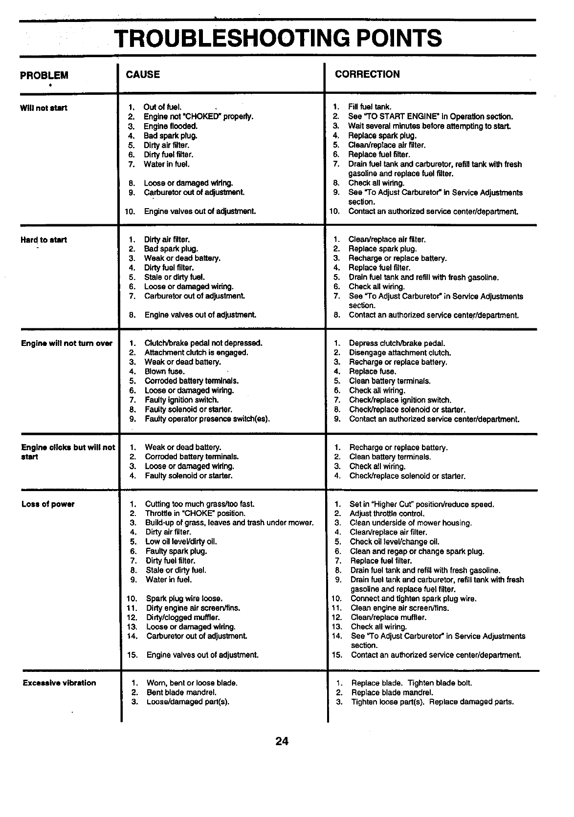
TROUBLESHOOTING POINTS
I I
CAUSE CORRECTION
PROBLEM
Willnotstart
Hard to start
Engine will not turn over
Engine clicks but will not
start
Loss of power
Excessive vibration
1. Out of fuel.
2. Engine not "CHOKED" properly.
3. Engine flooded.
4. Bad spark plug.
5. Dirty air tilter.
6. Dirty fuel tilter,
7. Water in fuel.
8. Looseordamagedwiring.
9. Carburetoroutof adjustrnenL
10. Enginevalvesoutof adjustment.
1. Dirty air filter,
2. Bad spark plug.
3. Weak or dead battery.
4. Dirty fuel filter.
5. Stale or dirty fuel.
6. Loose or damaged widng.
7. Carburetor out of adjustment
8. Engine valves out of adjustment.
1. Clutch/brakepedalnotdepressed.
2. Attachmentdutch is engaged.
3. Weak or dead battery.
4. Blownfuse.
5. Corrodedbatteryterminals.
6. Loose ordamagedwidng.
7. Faultyignitionswitch.
8. Faultysolenoidorstarter.
9. Faultyoperatorpresenceswitch(as).
1, Weak or dead battery.
2. Corroded battery terminals,
3. Loose or damaged widng.
4. Faulty solenoid or starter.
1. Cutting too much grass/too fast.
2. ThrottJein =CHOKE. position.
3. Build-up of grass, leaves and trash under mower.
4. Dirty air filter.
5. Low oil level/dirty oil,
6. Faulty spark plug.
7. Dirty fuel tilter.
8. Stale or dirty fuel.
9. Water in fuel.
10. Spark plug wire loose.
11. Dirty engine air scrasnifins.
12, Didy/clngged muffler.
13. Loose or damaged wiring.
14. Carburetor out of adjustmanL
15. Engine valves out of adjustment.
1. Worn.bentorloose blade.
2. Bentblade mandrel.
3. Loose/damagadpart(s).
1. Fillfuel tank.
2. See =TOSTART ENGINE" inOperationsection.
3. Wait severalminutesbeforeattemptingto start.
4. Replacesparkplug.
5. Clean/replaceairfilter.
6. Replacefuel filter.
7. Drainfuel tankand carburetor,refilltank with fresh
gasolineandreplacefuelfilter.
8. Checkall wiring.
9. See =ToAdjustCarburetor"in ServiceAdjustments
section.
10. Contactan authorized servicecanter/departmant.
1. Clean/repleceairfilter.
2. Replacesparkplug.
3. Rechargeorreplacebattery.
4. Replacefuel filter.
5. Drainfueltank and refillwithfreshgasoline.
6. Checkallwiring.
7. See =ToAdjustCarburetor";nServiceAdjustments
section.
8. Contactan authorizedservicecanter/departmant.
1. Depress cfutchrorake pedal.
2. Disengage attachment clutch.
3. Recharge or replace battery.
4. Replace fuss.
5. Clean battery terminals.
6. Check all wiring.
7, Check/replace ignition switch.
8. Check/replace solenoid or starter.
9. Contact an authorized service center/department.
1. Rechargeor replacebattery.
2. Cleanbatteryterminals.
3. Checkall widng.
4. Check/replacesolenoidorstarter.
1. Set in =Higher Cut" position/reduce speed,
2. Adjust throttle control.
3. Clean underside of mower housing.
4. Clean/replace air filter.
5, Check oil level/changa oil.
6. Clean and rsgap or change spark plug.
7. Replace fuel filter.
8. Drain fuel tank and refill with fresh gasoline.
9. Drain fuel tank and carbure_r, refill tank with fresh
gasoline and replace fuel filter.
10. Connect and tighten spark plug wire.
11, Clean engine air screen/fins.
12. Clean/replace muffler.
13. Check all wiring.
t 4. See =To Adjust Carburetor" in Service Adjustments
section.
15. Contact an authorized service center/department.
1. Replace blade. Tighten blade bolt.
2. Replace blade mandrel.
3. Tighten loose part(s). Replace damaged pads.
24

TROUBLESHOOTING POINTS
PROBLEM CAUSE CORRECTION
Engine continues to run
when operator leaves seal
with attaohment clutch
engaged
Poor cut -uneven
"Mower blades will not
•rotate
Poor grass discharge
Headlight(a) not working
(if so equipped)
Battery will not charge
Engine "backfires"
when turning englne
"OFF"
1. Faulty operator-safety presence control system.
1. Worn, bent or loose blade.
2. Mower deck not level.
3. Buildup of grass, leaves, and trash under mower.
4. Bunt blade mandrel,
5. Clogged mower deck vent holes from buildup of
grass, leaves, and trash around mandrels.
1. Obstructionindutch mechanism.
2. Worn/damagedmowerddvebelt.
3. Frozenidlerpulley.
4. Frozenblademandrel.
1. Engine speed too slow,
2. Travel speed too fast.
3. Wet grass.
4. Mower deck not level.
5. Low/uneven tire air pressure,
6. Worn, bent or loose blade.
7. Buildup of grass, leaves and bash under mower.
8. Mower ddve belt worn.
9. Blades impropedy installed.
10. Improper blades used,
11. Clogged mower deck vent holes from buildup of
grass, leaves, and trash around mandrels.
1. Switch is "OFF".
2. Bulb(s) burned out,
3. Faulty light switch,
4. Loose or damaged wiring.
5. Blown fuse.
1. Bad battery ceil(s),
2. Poor cable connections.
3. Faulty regulator (if so equipped).
4. Faulty alternator.
1. Enginethrottlecontrolnotset at "SLOW"
positionfor 30 secondsbeforestoppingengine,
Check wiring, switches and connections. If not
corrected, contact an authodzed service center/
department.
1. Replace blade. TightenbladepolL
2. Levelmowerdeck.
3. Cleonundersideof mower housing.
4. Replace blademandrel.
5. Clean aroundmandrelsto openventholes.
1. Removeobstruction.
2. Replace mower drivebelt.
3. Replace idlerpulley,
4. Replace blademandrel.
1. Place throtlle control in "FAST" position.
2. Shift to slower speed.
3. Allow grass to dry before mowing.
4. Level mower deck.
5. Check tires for proper air pressure.
6. Replace/sharpen blade. Tighten blade bolL
7. Clean ur)dsrside of mower housing.
8. Replace mower drive belt.
9. Reinstall blades sharp edge down.
10. Replace with blades listed in this manual.
11. Clean around mandrels to open vent holes.
1. Turn switch"ON'.
2. Replace bulb(s).
3. Check/replace light switch.
4. Check wiring and connections.
5. Replace fuse.
1. Replacebattery.
2. Check/cleanallconnections.
3, Replaceregulator.
4. Replaceaifemator.
1. Move throttle control to "SLOW" position and allow
to idle for 30 seconds before stopping engine.
25

ii¸ lii] f_ _ _l,lkJ, l_ j._._, ,_, _. L, _, , , Lj Ii
SERVICE NOTES
•I•i I i
26
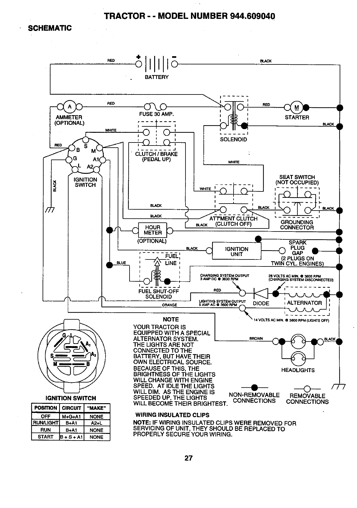
SCHEMATIC
TRACTOR - - MODEL NUMBER 944.609040
BATTERY
(
)
IGNITION SWITCH
RED
WHITE
POSITION CIRCUIT "MAKE"
OFF M÷G+A1 i NONE I
RU , HTI=-A,I I
RUN B+AI NONE I
START B+S+A1 NONE
FUSE30AMP.
BLAC_
BLACX
HOUR
METER
(OPTIONAL)
BLACK
¢ -- --i
____.,,_FUELI
FUELSHUT-OFF
SOLENOID I
ORANGE
NOTE
YOUR TRACTOR IS
EQUIPPED WITH A SPECIAL
ALTERNATOR SYSTEM.
THE LIGHTS ARE NOT
CONNECTED TO THE
BATTERY, BUT HAVE THEIR
OWN ELECTRICAL SOURCE.
BECAUSE OF THIS, THE
BRIGHTNESS OF THE LIGHTS
WILL CHANGE WITH ENGINE
SPEED. AT IDLE THE LIGHTS
REDSTARTER
BLACK
SEATSWITCH
(NOTOCCUPIED)
-IIi_I ........ i__I
GROUNDING
CONNECTOR
(_ IGNITIONUNIT
ASPARK
PLUG L
_GAP F
I (2 PLUGS ON
TWIN CYL. ENGINES)
CHARGING SYSTEM OUTPUT 28 VOLTS AC MIN, • 3600 RPM
3 AMP DC O 3G00 RPM (CHARGING SYSTEM DISCONNECTS[
REEO t_
_,_ s#_TE_o=P_
\
--'4VOLTSAC MIN ; 3_RPM(L_HTSO_F)
BROWN
HEADLIGHTS
WILL DIM. AS THE ENGINE IS 0" _:_ /-_
SPEEDED UP, THE LIGHTS NON-REMOVABLE REMOVABLE
WILL BECOME THEIR BRIGHTEST. CONNECTIONS CONNECTIONS
WIRING INSULATED CLIPS
NOTE: IF WIRING INSULATED CLIPS WERE REMOVED FOR
SERVICING OF UNIT, THEY SHOULD BE REPLACED TO
PROPERLY SECURE YOUR WIRING.
27
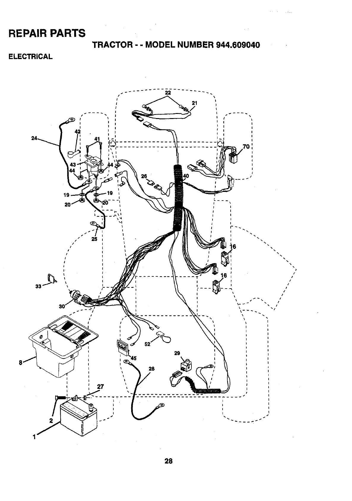
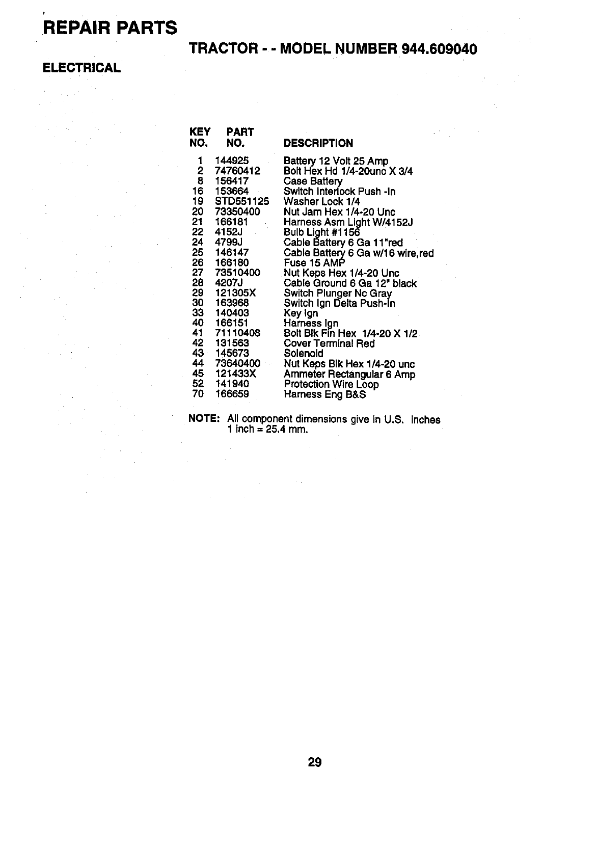
REPAIR PARTS
TRACTOR --MODEL NUMBER 944.609040
ELECTRICAL
LI _\
I I
II
41
25
I
7O
28
REPAIR PARTS
TRACTOR --MODEL NUMBER 944.609040
ELECTRICAL
KEY PART
NO. NO. DESCRIPTION
1 144925
2 74760412
8 156417
16 153664
19 STD551125
20 73350400
21 166181
22 4152J
24 4799J
25 146147
26 166180
27 73510400
28 4207J
29 121305X
30 163968
33 140403
40 166151
41 71110408
42 131563
43 145673
44 73640400
45 121433X
52 141940
70 166659
Battery 12 Volt 25 Amp
Bolt Hex Hd 1/4-20unc X3/4
Case Battery
Switch Interlock Push -In
Washer Lock 1/4
Nut Jam Hex 1/4-20 Unc
Harness Asm Light W/4152J
Bulb Light #1156 .
Cable Battery 6 Ga 11 red
Cable Battery 6 Ga w/16 wire,red
Fuse 15 AMP
Nut Keps Hex 1/4-20 Unc
Cable Ground 6 Ga 12" black
Switch Plunger Nc Gray
Switch Ign Delta Push-In
Key Ign
Harness lg_
Bolt BIk Fin Hex 1/4-20 X 1/2
Cover Terminal Red
Solenoid
Nut Keps BIk Hex 1/4-20 unc
Ammeter Rectangular 6 Amp
Protection Wire Loop
Harness Eng B&S
NOTE: All component dimensions give in U.S. inches
1 inch = 25,4 mm.
29
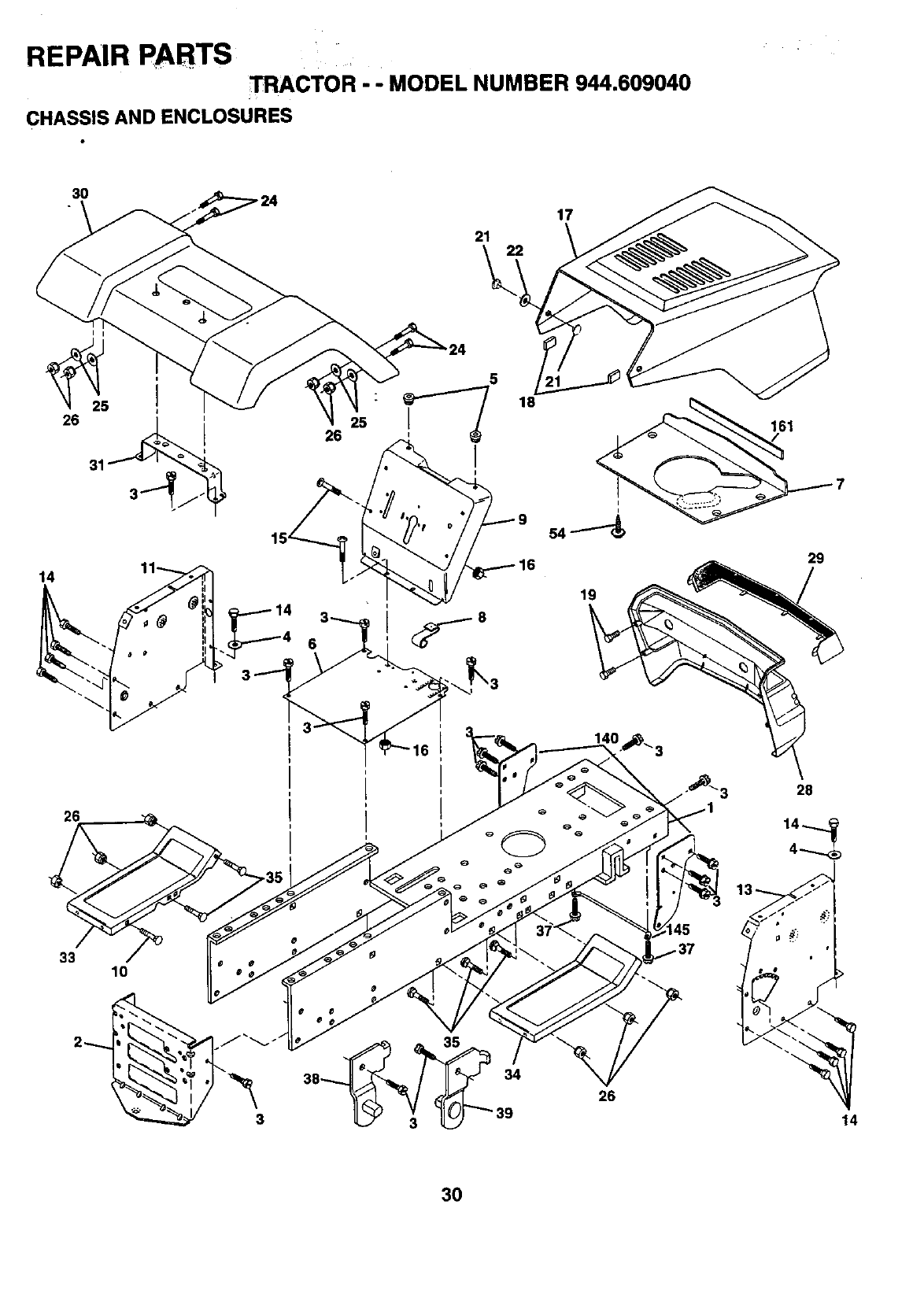
REPAIR PARTS _ACTOR - - MODEL NUMBER 944.609040
CHASSIS AND ENCLOSURES
30
21 22
17
14
26
26
5
25 :
I
18
161
33 10
3
26
14
3O
REPAIR PARTS
TRACTOR -- MODEL NUMBER 944.609040
CHASSIS AND ENCLOSURES
KEY PART
NO. NO. DESCRIPTION
1165480
2 140356
317490612
4STD551025
5 155272
6155924X012
7126842X
8 155138
9 166322X010
10 STD533710
11 155927
13 155934X010
14 17490608
15 74180512
16 STD541431
17 154989X558
18 126938X
19 17411310
21 122933X
22 124479X
24 STD523710
25 19131312
26 STD541437
28 140135X428
29 124029X599
30 166884X558
31 136619
33 145244X558
34 145243X558
35 STD533707
37 17490508
38 139886
39 139887
54 161464
140 158418
145 156524
161 161547
-- 5479J
Chassis
Drawbar Stretch
Screw Thdrol 3/8-16 x 3/4 Ty-tt
Washer 13/32 x3/4 x 16 Ga.
Bumper Hood/Dash
Saddle
Shield, Heat, Hood
Clip Retainer Slide-On
Dash Silkscreened
Bolt Carriage 3/8-16 x 1
Panel Dash Lh
Panel Dash Rh Slkscr
Screw Thdrol 3/8-16 x 112Ty-tt
Screw Mach Trhd 5/16-18 unc x 3/4
Nut Keps 5/16-18
Hood Asm Pnt Weld Slpe
Bumper Hood
Screw
Rivet Ratchet Nylon
Washer Nylon BIk 28 x 75 x 19
Bolt Fin Hex 3/8-!6 x 1 Gr. 5
Washer 13/32 x 13/16 x 12 Ga
Nut Lock Hex w/Ins 3/8-16
Grille Black
Lens Headlight Bar Clear
Fender Pnt
Bracket Pnt Fender
Footrest Pnt Lh
Footrest Pnt Rh
Bolt Carriage 3/8-16 x 3/4
Screw Thdrol 5/16-18 x 1/2
Bracket Asm. Pivot LH
Bracket Asm. Pivot RH
Screw Hex Wshd 8-18 x 718
Bracket Suspension Front
Rod Pivot Chassis/Hood
Extrusion Hood
Plug Button Black
NOTE: All component dimensions given in U.S. inches
1inch = 25.4 mm
31
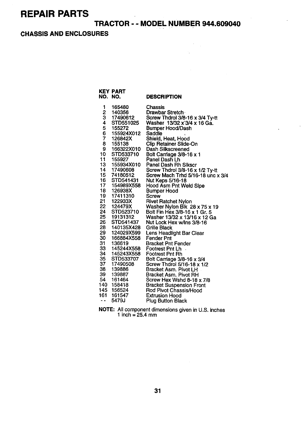
REPAIR PARTS
TRACTOR - - MODEL NUMBER 944.609040
DRIVE
77
6
51 5
18
150
_48
151
51
>3
25 .J
J
29 26
27
53
32
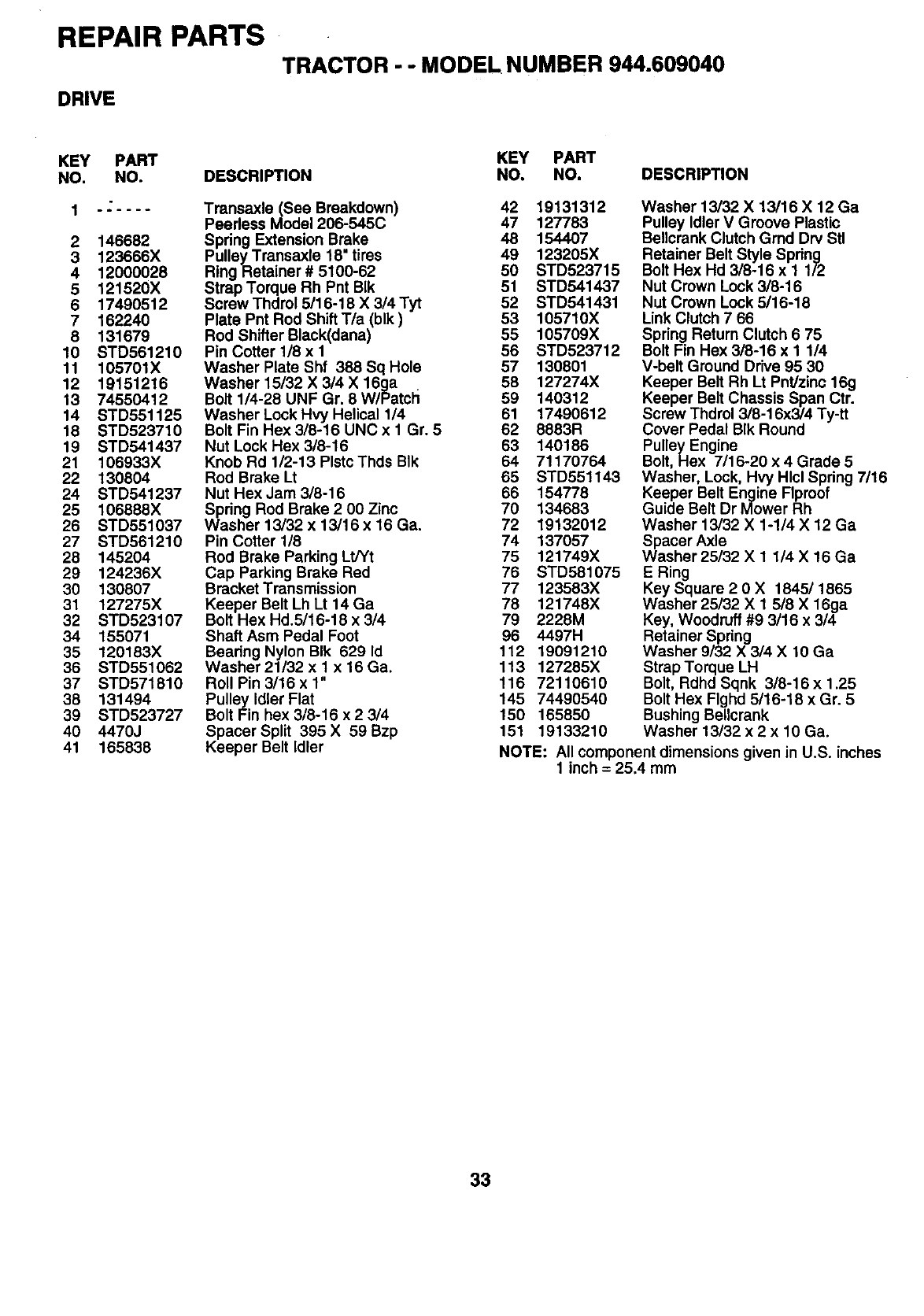
REPAIR PARTS
TRACTOR - -MODEL NUMBER 944.609040
DRIVE
KEY PART KEY PART
NO. NO. DESCRIPTION NO. NO. DESCRIPTION
2 146682
3 123666X
4 12000028
5 121520X
6 17490512
7 162240
8 131679
10 STD561210
11 105701X
12 19151216
13 74550412
14 STD551125
18 STD523710
19 STD541437
21 106933X
22 130804
24 STD541237
25 106888X
26 STD551037
27 STD561210
28 145204
29 124236X
30 130807
31 127275X
32 STD523107
34 155071
35 120183X
36 STD551062
37 STD571810
38 131494
39 STD523727
40 4470J
41 165838
Transaxle (See Breakdown) 42 19131312
Peerless Model 206-545C 47 127783
Spring Extension Brake 48 154407
PulleyTransaxle 18" tires 49 123205X
RingRetainer # 5100-62 50 STD523715
Strap Torque Rh Pnt BIk 51 STD541437
Screw Thdrol 5116-18 X 3/4 Tyt 52 STD541431
Plate Pnt Rod Shift T/a (blk) 53 105710X
Rod Shifter Black(dana) 55 105709X
Pin Cotter 1/8 x I 56 STD523712
Washer Plate Shf 388 Sq Hole 57 130801
Washer 15/32 X 3/4 X 16ga . 58 127274X
Bolt 1/4-28 UNF Gr. 8 W/Patch 69 140312
Washer Lock Hvy Helical 1/4 61 17490612
Bolt Fin Hex 3/8-16 UNC x 1 Gr. 5 62 8883R
Nut Lock Hex 3/8-16 63 140186
Knob Rd 1/2-13 PlstcThds BIk 64 71170764
Rod Brake Lt 65 STD551143
Nut Hex Jam 3/8-16 66 154778
Spring Rod Brake 2 00 Zinc 70 134683
Washer 13/32 x 13/16 x 16 Ga. 72 19132012
Pin Cotter 1/8 74 137057
Rod Brake Parking Lt/Yt 75 121749X
Cap Parking Brake Red 76 STD581075
Bracket Transmission 77 123583X
Keeper Belt Lh Lt 14 Ga 78 121748X
Bolt Hex Hd.5/16-18 x 3/4 79 2228M
Shaft Asm Pedal Foot 96 4497H
Beadng Nylon BIk 629 Id 112 19091210
Washer 21/32 x t x 16 Ga. 113 127285X
Roll Pin 3/16 x 1" 116 72110610
Pulley Idler Flat 145 74490540
Bolt Fin hex 3/8-16 x 2 3/4 150 165850
Spacer Split 395 X 59 Bzp 151 19133210
Keeper Belt Idler
Washer 13/32 X 13/16 X 12 Ga
Pulley Idler V Groove Plastic
Bellcrank Clutch Grad Drv Stl
Retainer Belt Style Spring
Bolt Hex Hd 3/8-16 x 1 112
Nut Crown Lock 3/8-16
Nut Crown Lock 5/16-18
Link Clutch 7 66
Spring Return Clutch 6 75
Bolt Fin Hex 3/8-16 x I 114
V-belt Ground Drive 95 30
Keeper Belt Rh Lt Pnt/zinc 16g
Keeper Belt Chassis Span Ctr.
Screw Thdrol 3/8-16x3/4 Ty-tt
Cover Pedal BIk Round
Pulley Engine
Bolt, Hex 7/16-20 x 4 Grade 5
Washer, Lock, Hvy Hlcl Spring 7/16
Keeper Belt Engine FIproof
Guide Belt Dr Mower Rh
Washer 13/32 X 1-1/4 X 12 Ga
Spacer Axle
Washer 25/32 X 1 1/4 X 16 Ga
E Ring
Key Square 2 0 X 1845/1865
Washer 25/32 X 1 518X 16ga
Key, Woodruff #9 3/16 x 3/4
Retainer Spring
Washer 9/32 X 3/4 X 10 Ga
Strap Torque LH
Bolt, Rdhd Sqnk 3/8-16 x 1.25
Bolt Hex Flghd 5116-18 x Gr. 5
Bushing Bellcrank
Washer 13/32 x 2 x 10 Ga.
NOTE: All component dimensions given in U.S. inches
1 inch = 25.4 mm
33
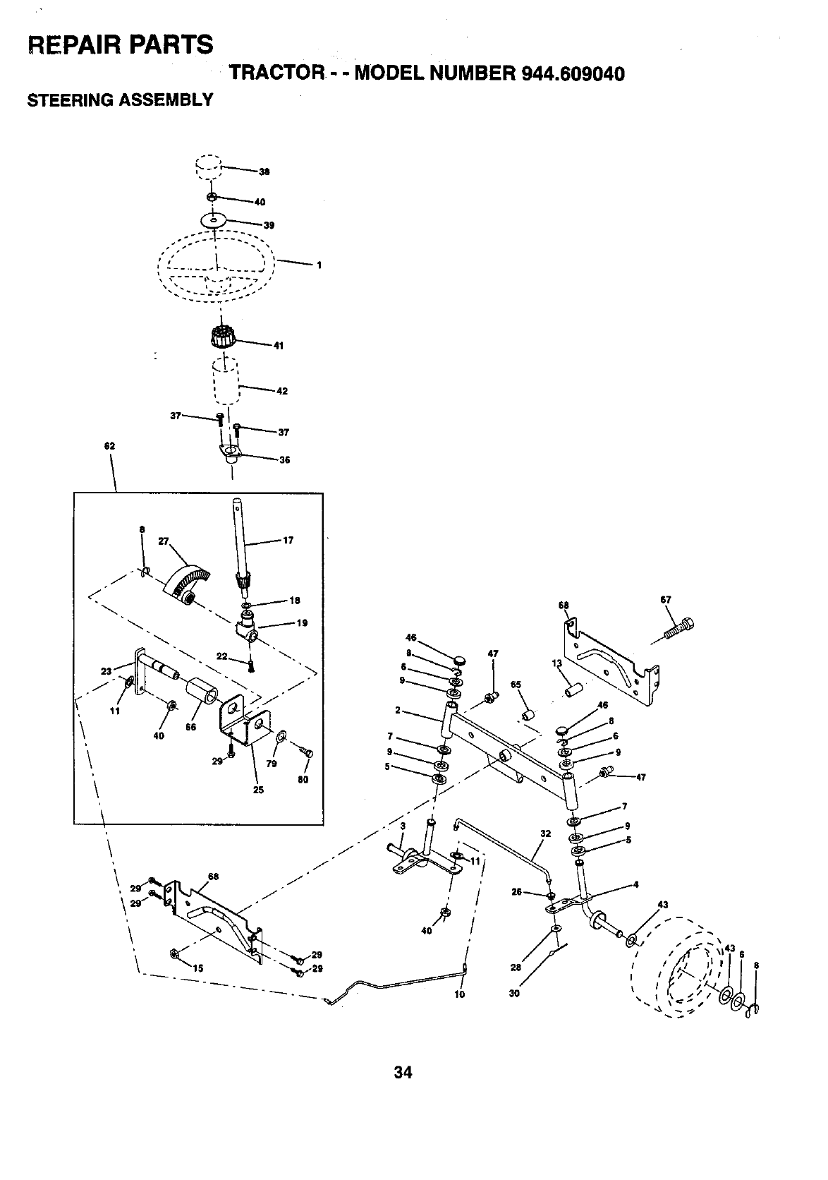
REPAIR PARTS
TRACTOR - -MODEL NUMBER 944.609040
STEERING ASSEMBLY
62
,"--"--42
Is
I
8
4O
117
25
47
3O
67
32
34
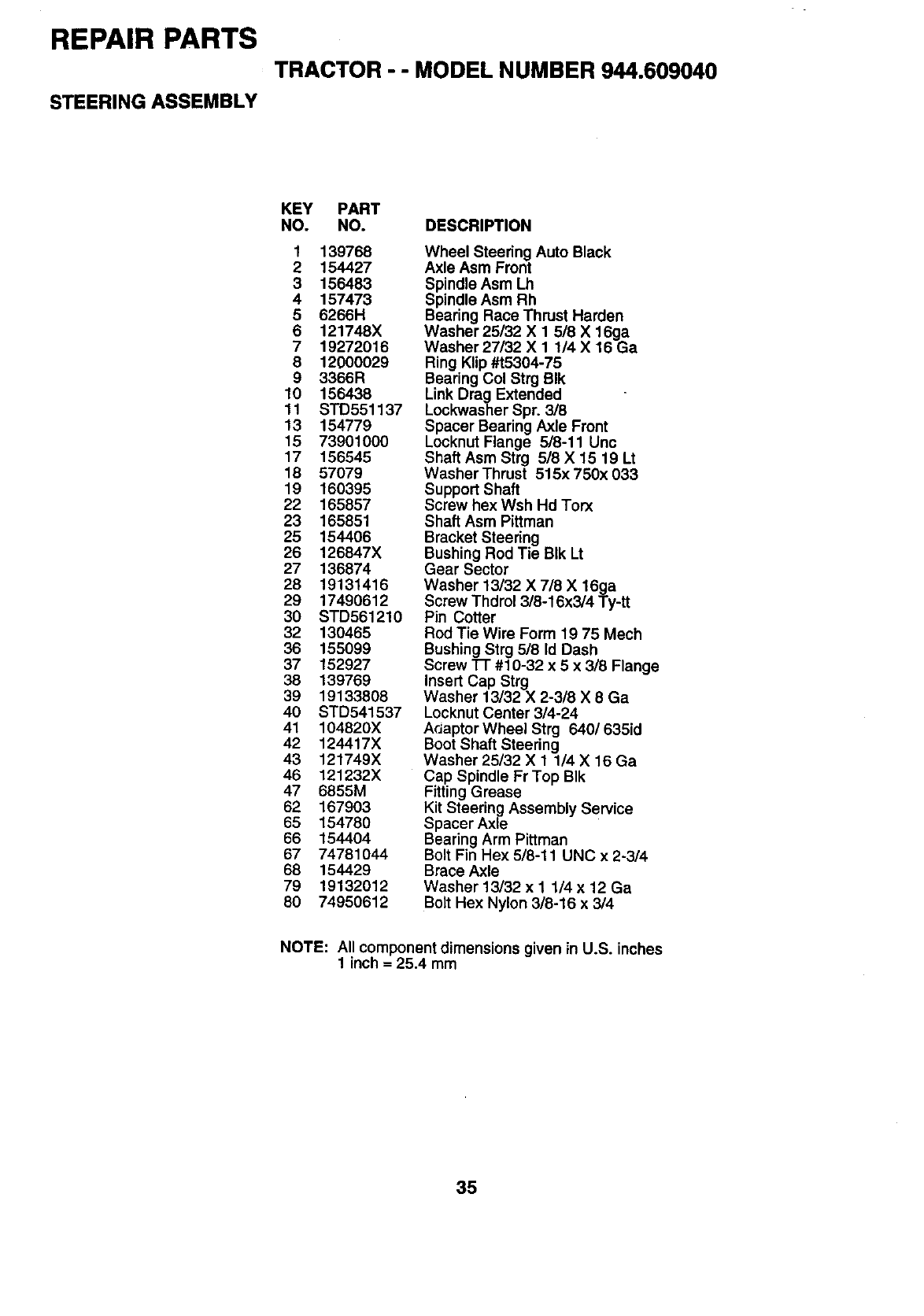
REPAIR PARTS
TRACTOR - - MODEL NUMBER 944.609040
STEERING ASSEMBLY
KEY PART
NO. NO. DESCRIPTION
1 139768
2 154427
3 156483
4 157473
5 6266H
6 121748X
7 19272016
8 12000029
9 3366R
10 156438
11 STD551137
13 154779
15 73901000
17 156545
18 57079
19 160395
22 165857
23 165851
25 154406
26 126847X
27 136874
28 19131418
29 17490612
3O STD561210
32 130465
36 155099
37 152927
38 139769
39 19133808
40 STD541537
41 104820X
42 124417X
43 121749X
48 121232X
47 6855M
62 167903
65 154780
66 154404
67 74781044
88 154429
79 19132012
60 74950612
Wheel Steering Auto Black
Axle Asm Front
Spindle Asm Lh
Spindle Asm Rh
Bearing Race Thrust Harden
Washer 25/32 X 1 5/8 X 16ga
Washer 27/32 X 1 1/4 X 16 Ga
Ring Klip #t5304-75
Bearing Col Strg BIk
Link Drag Extended
Lockwasher Spr. 3/8
Spacer Bearing Axle Front
Locknut Flange 5/8-11 Unc
Shaft Asm Strg 5/8X 15 19 Lt
WasherThrust 515x 750x 033
Support Shaft
Screw hex Wsh Hd Torx
Shaft Asm Pittman
Bracket Steering
Bushing Rod Tie BIk Lt
Gear Sector
Washer 13/32 X 7/8 X 16ga
Screw Thdrol 3/8-16x3/4 Ty-tt
Pin Cotter
Rod Tie Wire Form 19 75 Mech
Bushing Strg 5/8 Id Dash
Screw l-r #10-32 x 5x 3/8 Flange
Insert Cap Strg
Washer 13/32 X 2-3/8 X 8 Ga
Locknut Center 3/4-24
ArJaptor Wheel Strg 640/635id
Boot Shaft Steering
Washer 25/32 X 1 1/4 X 16 Ga
Cap Spindle Fr Top BIk
Fitting Grease
Kit Steering Assembly Service
Spacer Axle
Bearing Arm Pittman
Bolt Fin Hex 5/8-11 UNC x 2-3/4
Brace Axle
Washer 13/32 x 1 1/4 x 12 Ga
Bolt Hex Nylon 3/8-16 x 3/4
NOTE: All component dimensions given in U.S. inches
1 inch = 25.4 mm
35
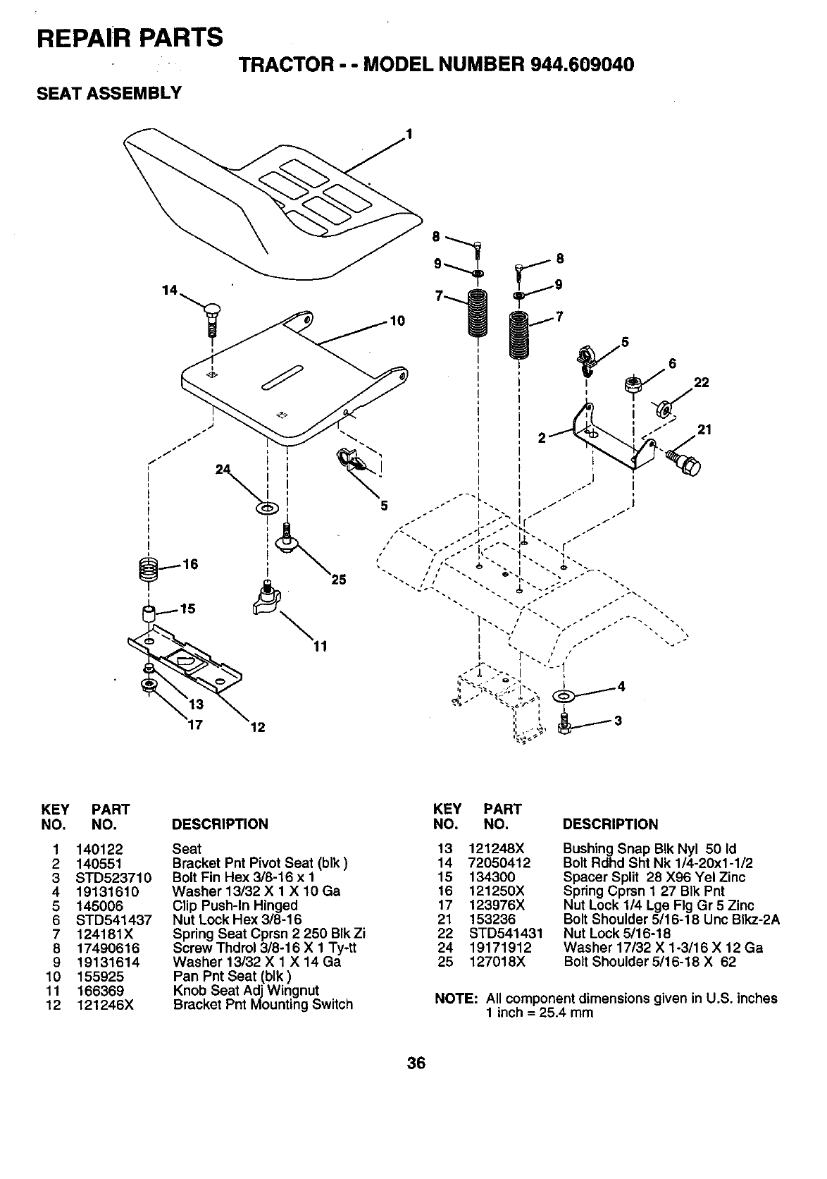
REPAIR PARTS
TRACTOR - - MODEL NUMBER 944.609040
SEAT ASSEMBLY
i
12
5
_7
5
22
21
KEY PART
NO. NO.
1140122
2140551
3 STD523710
419131610
5145006
6 STD541437
7 124181X
8 17490616
9 19131614
10 155925
11 166369
12 121246X
DESCRIPTION
Seat
Bracket Pnt Pivot Seat (blk)
Bolt Fin Hex 3/8-16 x 1
Washer 13/32 X 1 X 10 Ga
Clip Push-In Hinged
Nut Lock Hex 3/8-16
Spring Seat Cprsn 2 250 BIk Zi
Screw Thdrol 3/8-16 X 1 Ty-tt
Washer 13/32 X 1 X 14 Ga
Pan Pnt Seat (blk)
Knob Seat Adj Wingnut
Bracket Pnt Mounting Switch
KEY PART
NO. NO. DESCRIPTION
13 121248X
14 72050412
15 134300
16 121250X
17 123976X
21 153236
22 STD541431
24 19171912
25 127018X
Bushing Snap BIk Nyl 50 Id
Bolt Rdhd Sht Nk 1/4-20x1-1/2
Spacer Split 28 X96 Yel Zinc
Spring Cprsn 1 27 BIk Pnt
Nut Lock 1/4 Lge Fig Gr 5 Zinc
Bolt Shoulder 5/16-18 Unc BIkz-2A
Nut Lock 5116-18
Washer 17/32 X 1-3/16 X 12 Ga
Bolt Shoulder 5/16-18 X 62
NOTE: All component dimensions given in U.S. inches
1 inch = 25.4 mm
36
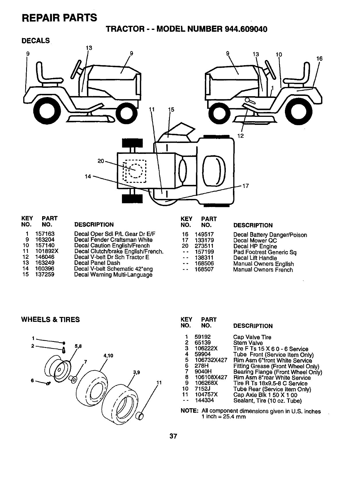
REPAIR PARTS
DECALS
13
9
14
TRACTOR - - MODEL NUMBER 944.609040
20_
9
11
12
t3 10 16
KEY PART
NO. NO.
1157163
9 163204
10 157140
11 101892X
12 146046
13 163249
14 160396
15 137259
DESCRIPTION
Decal Oper Sdl P/L Gear Dr E/F
Decal Fender Craftsman White
Decal Caution English/French
Decal Clutch/brake English/French.
Decal V-belt Dr Sch Tractor E
Decal Panel Dash
Decal V-belt Schematic 42"eng
Decal Warning Multi-Language
KEY PART
NO. NO.
16 149517
17 133179
20 273511
-- 157199
-- 138311
-- 168506
-- 168507
DESCRIPTION
Decal Battery Danger/Poison
Decal Mower QC
Decal HP Engine
Pad Footrest Genedc Sq
Decal Lift Handle
Manual Owners English
Manual Owners French
WHEELS & TIRES
4,10
KEY PART
NO. NO. DESCRIPTION
11
1 59192
265139
3106222X
459904
5106732X427
6278H
7 9040H
8 106108X427
9 106268X
10 7152J
11 104757X
- - 144334
Cap Valve Tire
Stem Valve
Tire F Ts 15 X 6 0 - 6 Service
Tube Front (Service Item Only)
Rim Asm 6"front White Service
Fitting Grease (Front Wheel Only)
Bearing Flange (Front Wheel Only)
Rim Asm 8"rear White Service
Tire R Ts 18x9.5-8 C Service
Tube Rear (Service Item Only)
Cap Axle BIk 1 50 X 1 00
Sealant, Tire (10 oz. Tube)
NOTE: All component dimensions given in U.S. inches
1 inch = 25.4 mm
37
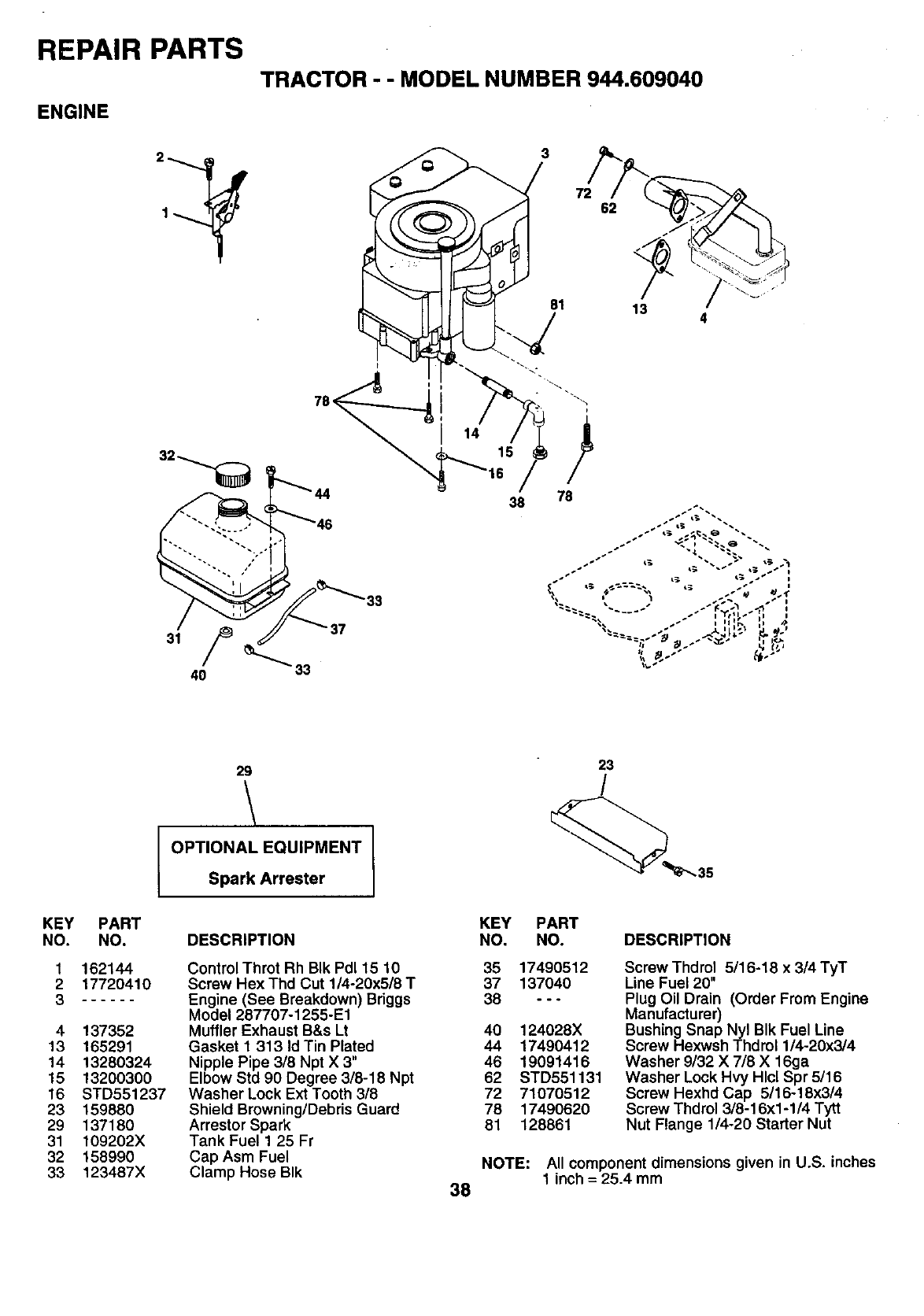
REPAIR PARTS
TRACTOR - - MODEL NUMBER 944.609040
ENGINE
33
3
81
38 78
34
KEY
NO.
1
2
3
4
13
14
15
16
23
29
31
32
33
L
PART
NO.
162144
17720410
137352
165291
13280324
13200300
STD551237
159880
137180
109202X
158990
123487X
29
OPTIONAL EQUIPMENT
Spark Arrester
DESCRIPTION
Control Throt Rh BIk Pd115 10
Screw Hex Thd Cut 1/4-20x5/8 T
Engine (See Breakdown) Briggs
Model 287707-1255-E1
Muffler Exhaust B&s Lt
Gasket 1 313 Id Tin Plated
Nipple Pipe 3/8 Npt X 3"
Elbow Std 90 Degree 3/8-18 Npt
Washer Lock Ext Tooth 3/8
Shield Browning/Debris Guard
Arrestor Spark
Tank Fuel 1 25 Fr
Cap Asm Fuel
Clamp Hose BIk 38
23
/
KEY PART
NO. NO. DESCRIPTION
35 17490512
37 137040
38 ---
40 124028X
44 17490412
46 19091416
62 STD551131
72 71070512
78 17490620
81 128861
Screw Thd rol 5/16-18 x3/4 TyT
Line Fuel 20"
Plug Oil Drain (Order From Engine
Manufacturer)
Bushing Snap Nyl BIk Fuel Line
Screw Hexwsh Thdrol 1/4-20x3/4
Washer 9/32 X 718X 16ga
Washer Lock Hvy Hlcl Spr 5/16
Screw Hexhd Cap 5/16-18x3/4
Screw Thdrol 3/8-16xl -1/4 Tytt
Nut Flange 1/4-20 Starter Nut
NOTE: All component dimensions given in U.S. inches
1 inch = 25.4 mm
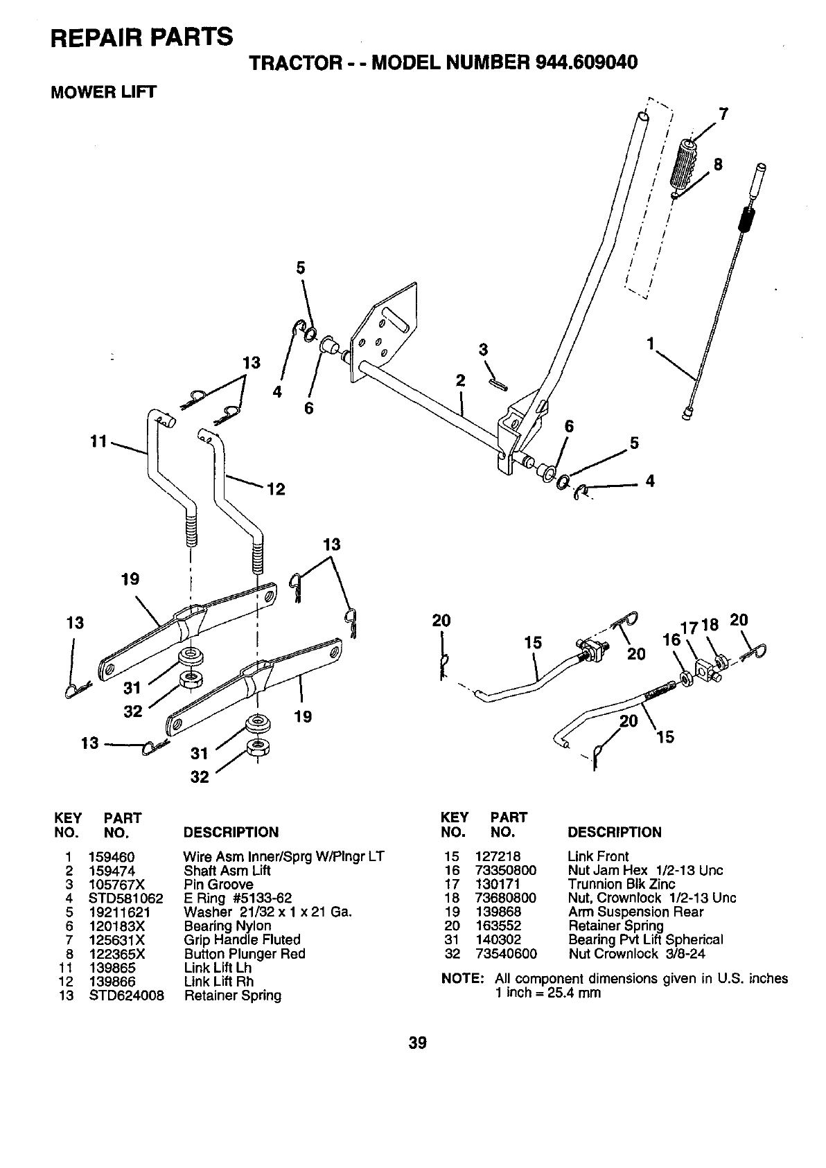
REPAIR PARTS
MOWER LIFT
TRACTOR - - MODEL NUMBER 944.609040
7
5
13
4 6
2
3
65
12
19
13
32 19
13
20
15 . ,_0 161718 20
20
15
KEY
NO.
1
2
3
4
5
6
7
8
11
12
13
PART
NO.
159460
159474
105767X
STD581062
19211621
120183X
125631X
122365X
139865
139866
STD624008
DESCRIPTION
Wire Asm Inner/Sprg W/Plngr LT
Shaft Asm Lift
Pin Groove
ERing #5133-62
Washer 21/32 x 1 x 21 Ga.
Bearing Nylon
Grip Handle Fluted
Button Plunger Red
Link Lift Lh
Link Lift Rh
Retainer Spring
KEY PART
NO. NO. DESCRIPTION
15 127218
16 73350800
17 130171
18 73680800
19 139868
20 163552
31 140302
32 73540600
Link Front
Nut Jam Hex 1/2-13 Unc
Trunnion BIk Zinc
Nut, Crownlock 1/2-13 Unc
Arm Suspension Rear
Retainer Spring
Bearing Pvt Lift Sphedcal
Nut Crownlock 3/8-24
NOTE: All component dimensions given in U.S. inches
1 inch = 25.4 mm
39
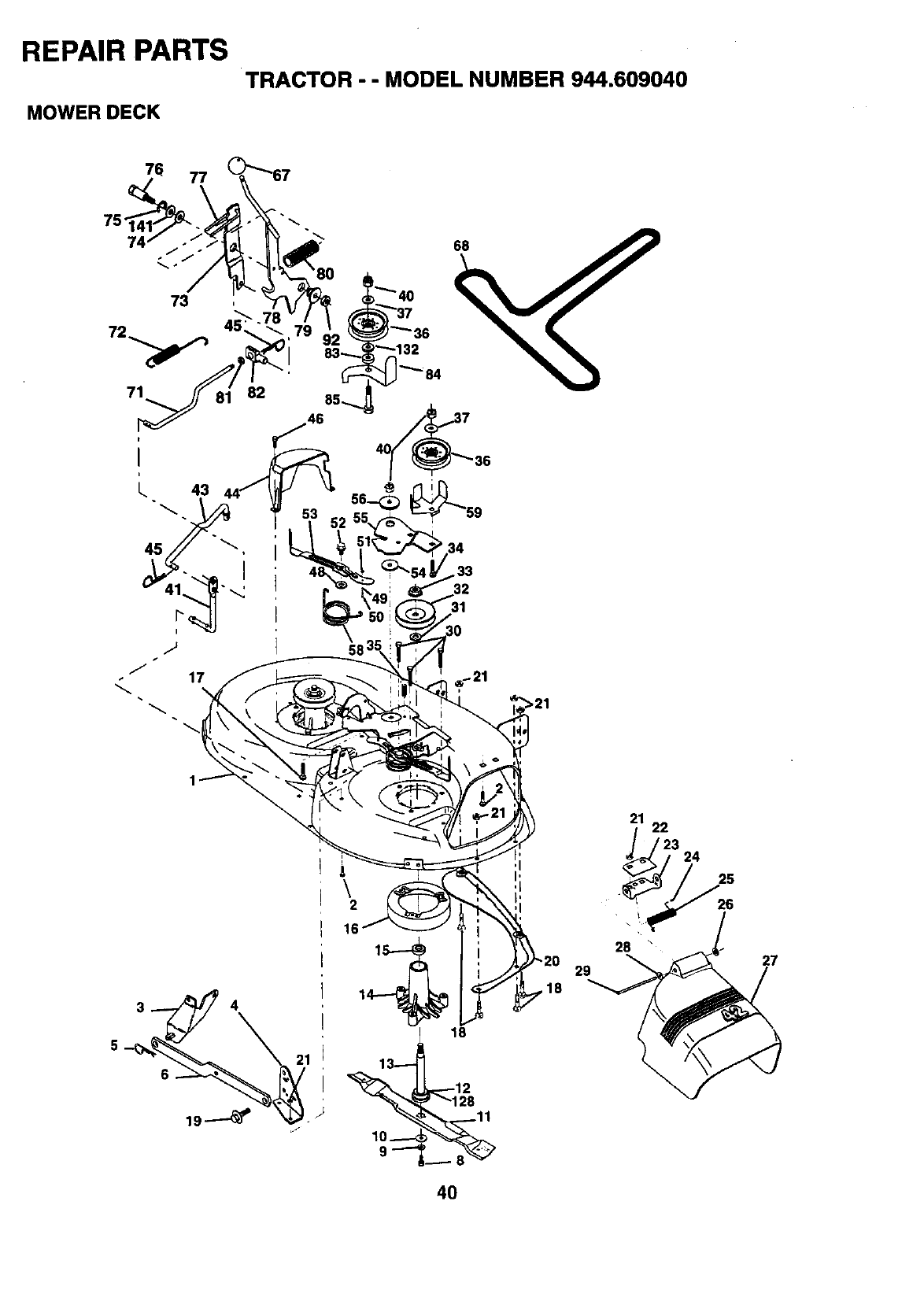
REPAIR PARTS
TRACTOR --MODEL NUMBER 944.609040
MOWER DECK
76 77
75"
73
71
t
I
I 43
45
82
31
58 3_
>21
\2
16
13
28 \
29 27
4O
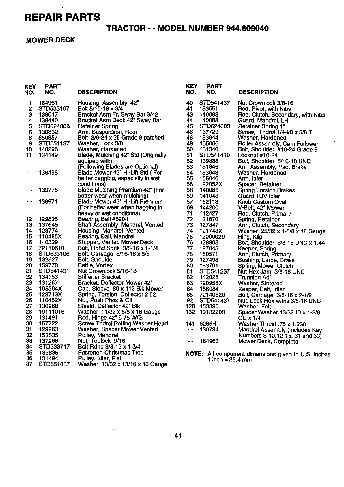
REPAIR PARTS
MOWER DECK
TRACTOR - - MODEL NUMBER 944.609040
KEY PART
NO. NO.
1164961
2 STD533107
3 138017
4 138440
5 STD624008
6 130832
8 850857
9 STD551137
10 140296
11 134149
.°
138498
139775
138971
12 129895
13 137645
14 128774
15 110485X
16 140329
17 72110610
18 STD533106
19 132827
20 159770
21 STD541431
22 134753
23 131267
24 105304X
25 123713X
26 110452X
27 130968
28 19111016
29 131491
30 157722
31 129963
32 153535
33 137266
34 STD533717
35 133835
36 131494
37 STD551037
DESCRIPTION
Housing Assembly, 42"
Bolt 5/16-18 x 3/4
Bracket Asm Fr. Sway Bar 3/42
Bracket Asm Deck 42" Sway Bar
Retainer Spring
Arm, Suspens=on, Rear
Bolt 3/8-24 x 25 Grade 8 patched
Washer, Lock 3/8
Washer, Hardened
Blade, Mulching 42" Std (Originally
equiped with)
(Following Blades are Optional)
Blade Mower 42" Hi-Lift Std ( For
better bagging, especially in wet
conditions)
Blade Mulching Premium 42" (For
better wear when mulching)
Blade Mower 42" Hi-Lift Premium
(For better wear when bagging in
heavy or wet conditions)
Bearing, Ball #6204
Shaft Assembly, Mandrel, Vented
Housing, Mandrel, Vented
Bearing, Ball, Mandrel
Stripper, Vented Mower Deck
Bolt, Rdhd Sqnk 3/8-16 x 1-1/4
Bolt, Carriage 5/16-18 x 5/8
Bolt, Shoulder
Baffle, Vortex
Nut Crownlock 5/16-18
Stiffener Bracket
Bracket, Deflector Mower 42"
Cap, Sleeve 80 x 112 BIk Mower
Spring, Torsion, Deflector 252
Nut, Push Phos & Oil
Shield, Deflector 42" BIk
Washer 11132 x 518 x 16 Gauge
Rod, Hinge 42" 6 75 WIG
Screw Thdrol Rolling Washer Head
Washer, Spacer Mower Vented
Pulley, Mandrel
Nut, Toplock 9/16
Bolt Rdhd 3/8-16 x 1 3/4
Fastener, Christmas Tree
Pulley, Idler, Flat
Washer 13/32 x 13116 x 16 Gauge
KEY PART
NO. NO. DESCRIPTION
40 STD541437
41 133551
43 140083
44 140088
45 STD624003
46 137729
48 133944
49 155066
50 131340
51 STD541410
52 139888
53 131845
54 133943
55 155046
56 122052X
58 140086
59 141043
67 162113
68 144200
71 142427
72 131870
73 127847
74 121748X
75 12000029
76 128903
77 127845
78 160571
79 127498
80 153701
81 STD541237
82 142028
83 120958X
84 156084
85 72140620
92 STD541437
128 153390
132 19132203
141 6266H
-- 130794
164963
Nut Crownlock 3/8-16
Rod, Pivot, with Nibs
Rod, Clutch, Secondary, with Nibs
Guard, Mandrel, LH
Retainer Spring 1"
Screw, Thdrol 1/4-20 x 5/8 T
Washer, Hardened
Roller Assembly, Cam Follower
Bolt, Shoulder #10-24 Grade 5
Locknut #10-24
Bolt, Shoulder 5116-18 UNC
Arm Assembly, Pad, Brake
Washer, Hardened
Arm, Idler
Spacer, Retainer
Spring Torsion Brakes
Guard TUV Idler
Knob Custom Oval
V-Belt, 42" Mower
Rod, Clutch, Primary
Spring, Retainer
Arm, Clutch, Secondary
Washer 25/32 x 1-5/8 x 16 Gauge
Ring, Klip
Bolt, Shoulder 3/8-16 UNC x 1.44
Keeper, Spring
Arm, Clutch, Primary
Bushing, Large, Brass
Spring, Mower Clutch
Nut Hex Jam 3/8-16 UNC
Trunnion Adj
Washer, Sintered
Keeper, Belt, Idler
Bolt, Carriage 3/8-16 x 2-1/2
Nut, Lock Hex w/Ins 3/8-16 UNC
Washer, Felt
Spacer Washer 13/32 ID x 1-3/8
OD x 1/4
Washer Thrust .75 x 1.230
Mandrel Assembly (Includes Key
Numbers 8-10,12-15, 31 and 33)
Mower Deck, Complete
NOTE: All component dimensions given in U.S. inches
1 inch = 25.4 mm
41
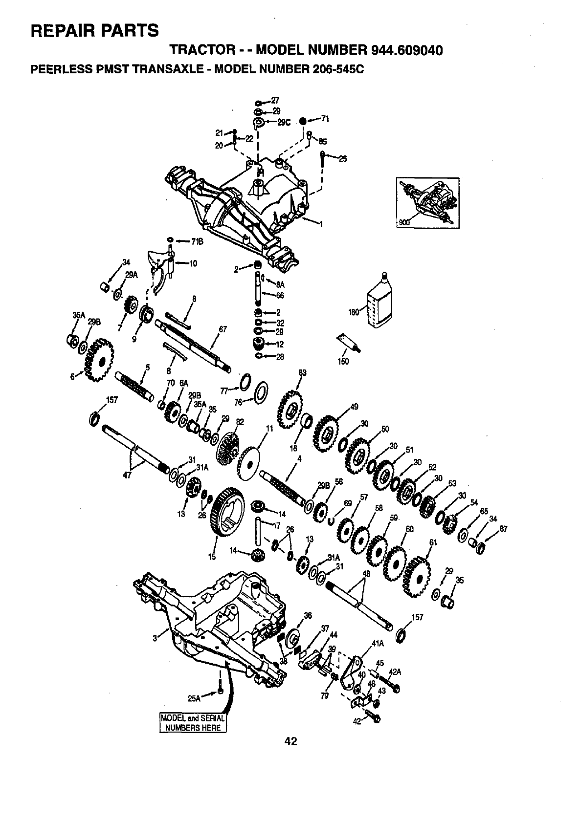
REPAIR PARTS
TRACTOR - -MODEL NUMBER 944.609040
PEERLESS PMST TRANSAXLE - MODEL NUMBER 206-545C
O.-27
47
9
8
70_
157
83
/
11
18
4
426
150
56
58 59
61
48 29
34
157
41A _/
42A
NUMBERSHERE
42
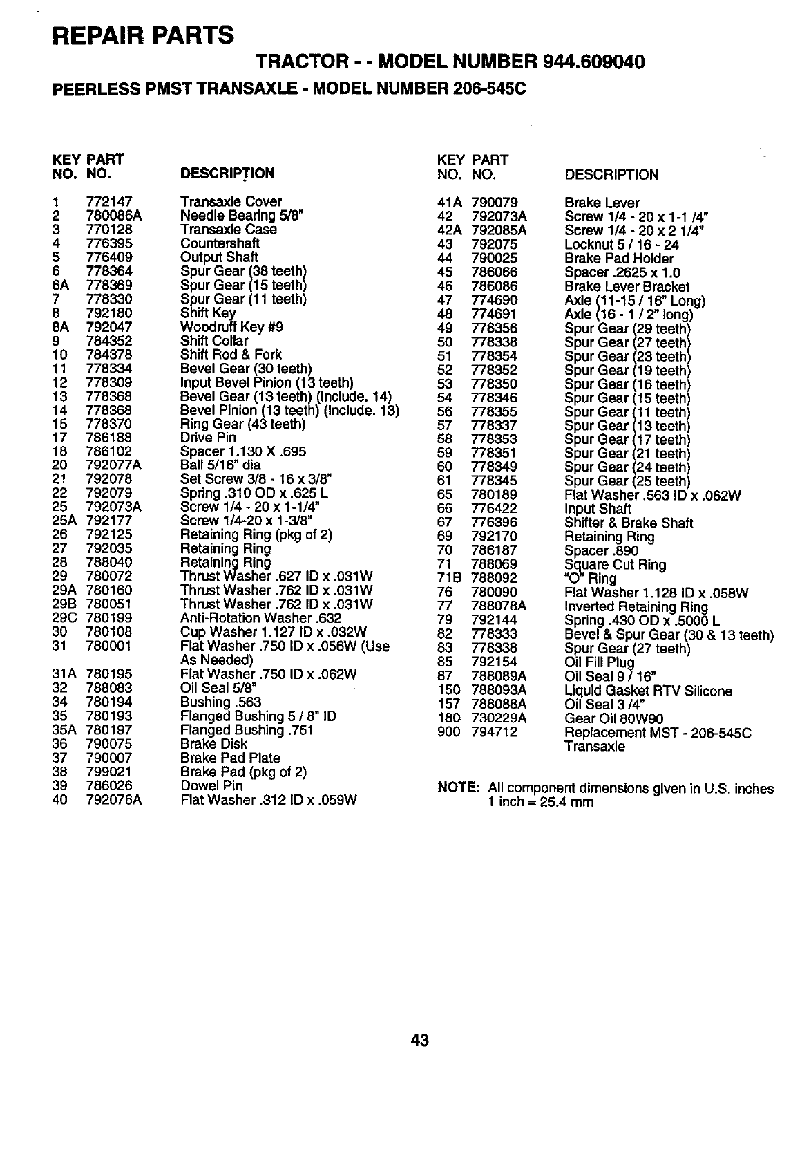
REPAIR PARTS TRACTOR --MODEL NUMBER 944.609040
PEERLESS PMST TRANSAXLE -MODEL NUMBER 206-545C
KEY PART KEY PART
NO. NO. DESCRIP'I'.ION NO. NO. DESCRIPTION
1772147
2 780066A
3 770128
4 776395
5 776409
6778364
6A 778369
7 778330
8 792180
6A 792047
9 764352
10 784378
11 778334
12 778309
13 778368
14 778368
15 778370
17 786188
18 786102
20 792077A
2! 792076
22 792079
25 792073A
25A 792177
26 792125
27 792035
28 788040
29 780072
29A 780160
29B 780051
29C 780199
30 780108
31 780001
31A 780195
32 788083
34 780194
35 780193
35A 780197
36 790075
37 790007
38 799021
39 786026
40 792076A
Transaxle Cover 41A 790079
Needle Bearing 5/8' 42 792073A
Transaxle Case 42A 792085A
Countershaft 43 792075
Output Shaft 44 790025
Spur Gear (38 teeth) 45 786066
Spur Gear (15 teeth) 46 786086
Spur Gear (11 teeth) 47 774690
Shift Key 46 774691
Woodruff Key #9 49 778356
Shift Collar 50 778338
Shift Rod & Fork 51 778354
Bevel Gear (30 teeth) 52 778352
Input Bevel Pinion (13 teeth) 53 778350
Bevel Gear (13 teeth) (Include. 14) 54 778346
Bevel Pinion (13 teeth) (Include. 13) 56 778355
Ring Gear (43 teeth) 57 778337
Drive Pin 68 778353
Spacer 1.130 X .695 59 778351
Ba_ 5/16" dis 60 778349
Set Screw 3/8 - 16 x 3/8" 61 778345
Spdng .310 OD x.625 L 65 780189
Screw 1/4 - 20 x 1-114" 66 776422
Screw 114-20 x 1-3/8" 67 776396
Retaining Ring (pkg of 2) 69 792170
Retaining Ring 70 786187
Retaining Ring 71 788069
Thrust Washer .627 ID x .031W 71B 788092
Thrust Washer .762 ID x .031W 76 780090
Thrust Washer .782 ID x .031W 77 788078A
Anti-Rotation Washer .632 79 792144
Cup Washer 1.127 ID x.032W 82 778333
Flat Washer .750 ID x .056W (Use 83 778338
As Needed) 85 792154
Flat Washer .750 ID x .062W 87 788089A
Oil Seal 5/8" 150 788093A
Bushing .563 157 788088A
Flanged Bushing 5 /8" ID 180 730229A
Flanged Bushing .751 900 794712
Brake Disk
Brake Pad Plate
Brake Pad (pkg of 2)
Dowel Pin
Flat Washer .312 ID x .059W
Brake Lever
Soraw 1/4 -20 x 1-1/4"
Screw 1/4 -20 x 2 1/4"
Locknut 5 /16 - 24
Brake Pad Holder
Spacer .2625 x 1.0
Brake Lever Bracket
Axle (11-15/16" Long)
Axle (16 -1/2" long)
Spur Gear (29 teeth)
Spur Gear (27 teeth)
Spur Gear (23 teeth)
Spur Gear (19 teeth)
Spur Gear (16 teeth)
Spur Gear (15 teeth)
Spur Gear 11 teeth)
Spur Gear 13 teeth)
Spur Gear 17 teeth)
Spur Gear (21 teeth)
Spur Gear (24 teeth)
Spur Gear (25 teeth)
Flat Washer .563 ID x .062W
Input Shaft
Shifter & Brake Shaft
Retaining Ring
Spacer .890
Square Cut Ring
"O" Ring
Flat Washer 1.128 ID x .058W
Inverted Retaining Ring
Spring .430 OD x .5000 L
Bevel & Spur Gear (30 & 13 teeth)
S_ur Gear (27 teeth)
Od Fill Plug
Oil Seal 9116"
Liquid Gasket RTV Silicone
Oil Seal 3/4"
Gear Oil 80W90
Replacement MST - 206-545C
Transaxle
NOTE: All component dimensions given in U.S. inches
1 inch = 25.4 mm
43
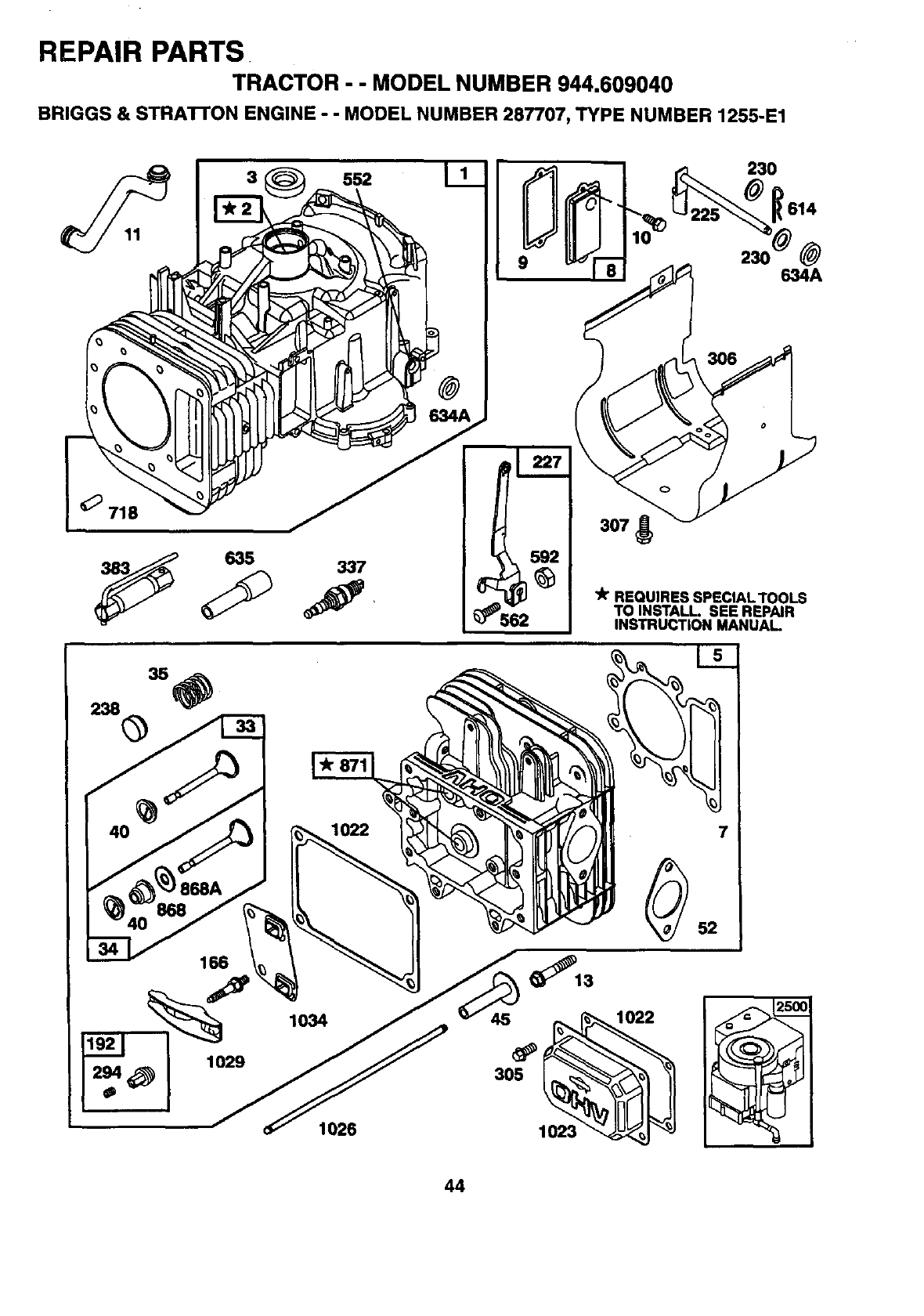
REPAIR PARTS
TRACTOR --MODEL NUMBER 944.609040
BRIGGS & STRAI-rON ENGINE - - MODEL NUMBER 287707, TYPE NUMBER 1255-E1
552
9634A
634A
635 337
562
lit REQUIRES SPECIAL TOOLS
TO INSTALL. SEE REPAIR
INSTRUCTION MANUAL
166
1026
_13
1023
44
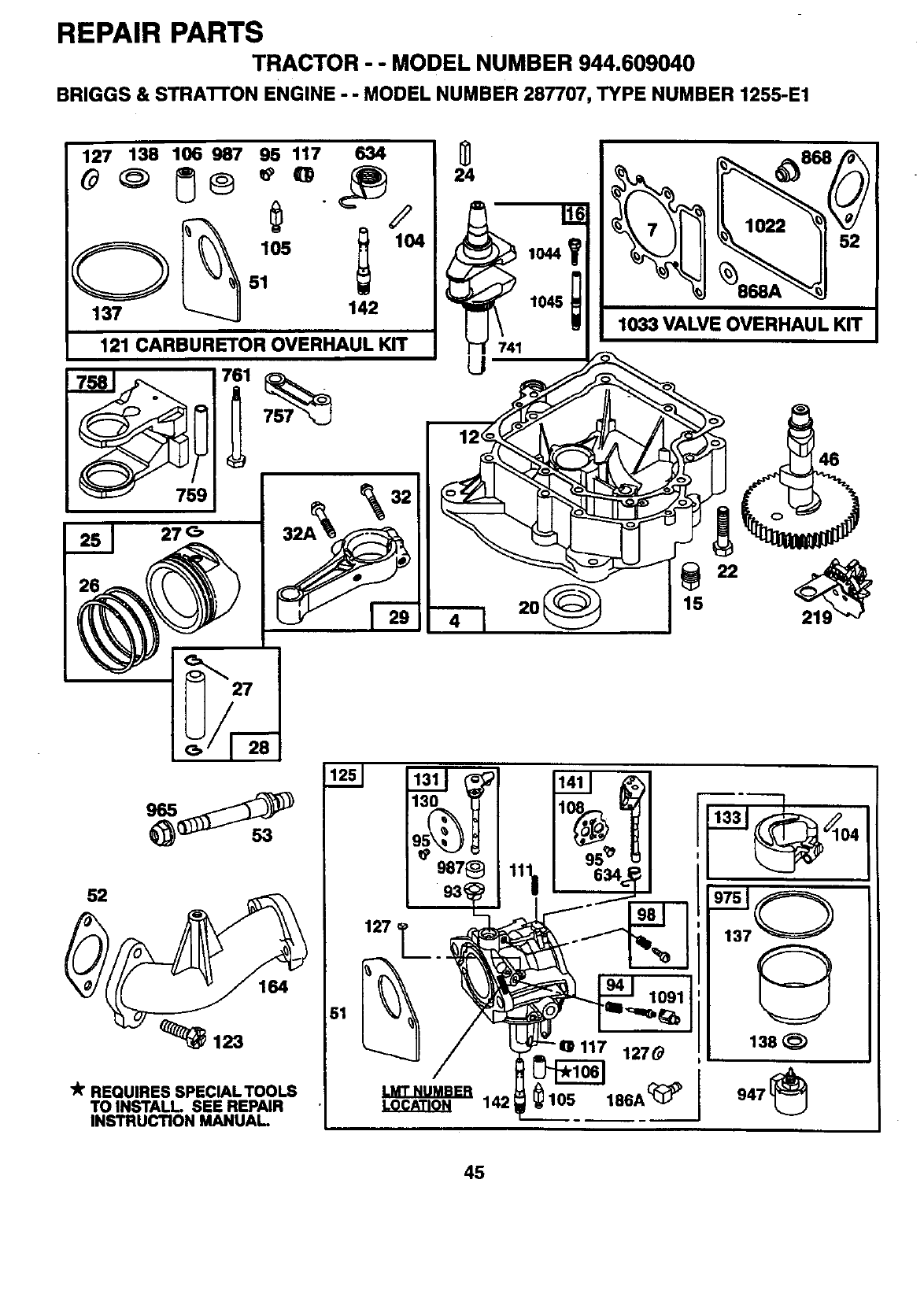
REPAIR PARTS
TRACTOR - - MODEL NUMBER 944.609040
BRIGGS & STRA'R'ON ENGINE - - MODEL NUMBER 287707, TYPE NUMBER 1255-E1
127 138 106 987 95 117 634
121 CARBURETOR OVERHAUL KIT
51 27
"k REQUIRES SPECIAL TOOLS
TO INSTALL. SEE REPAIR
INSTRUCTION MANUAl-
51
127 T._. __
LOCATION
1033 VALVE OVERHAUL KIT
142
1270
186A_
138 _)
45
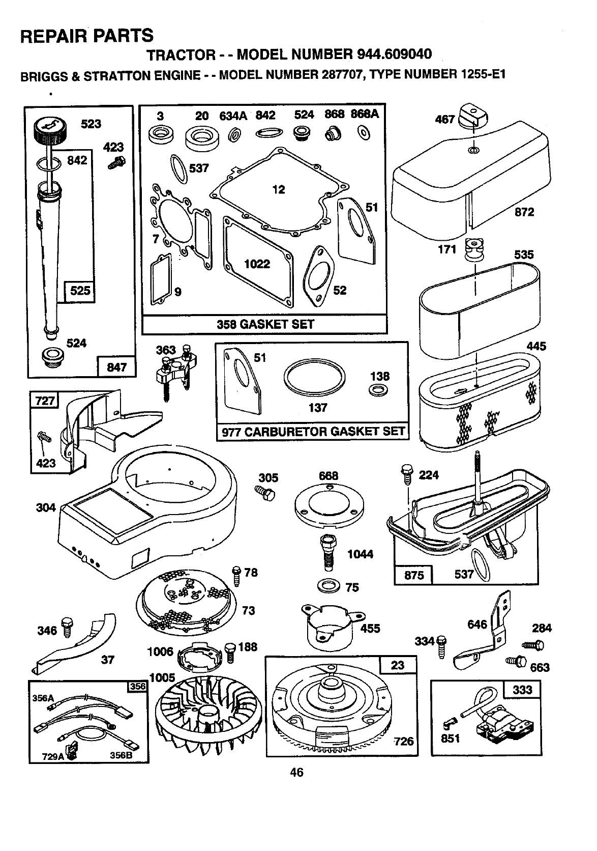
REPAIR PARTS
TRACTOR - - MODEL NUMBER 944.609040
BRIGGS & STRATTON ENGINE --MODEL NUMBER 287707, TYPE NUMBER 1255-E1
523
423
_524
7271
3 20 634A 842 524 868 868A
358 GASKET SET
1O138
137
977 CARBURETOR GASKET SET
467
171 _535
445
46
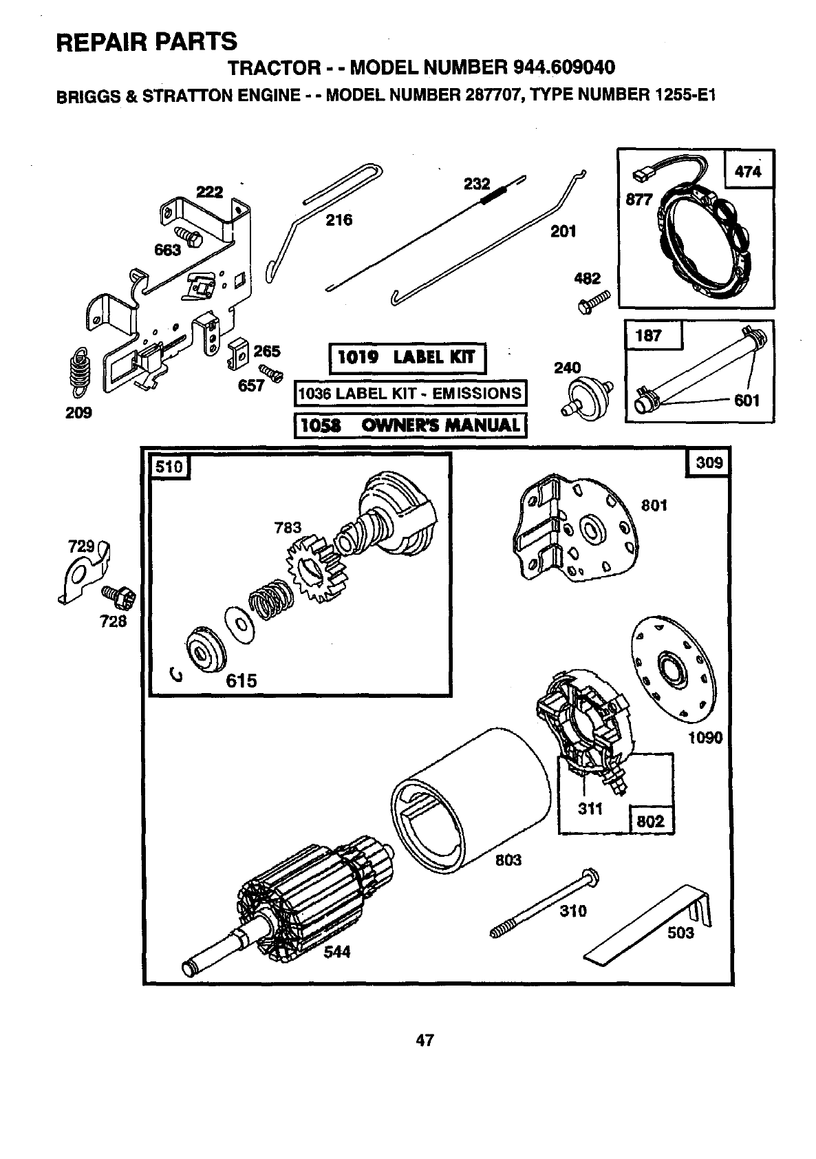
REPAIR PARTS
TRACTOR - - MODEL NUMBER 944.609040
BRIGGS & STRATTON ENGINE - - MODEL NUMBER 287707, TYPE NUMBER 1255-E1
729
728
265
615
2
1019 LABEL KIT I : 24O
11036 LABEL KIT- e, lsSloNsI,_
II0U OWNen MANUALI
783
311
801
1090
47
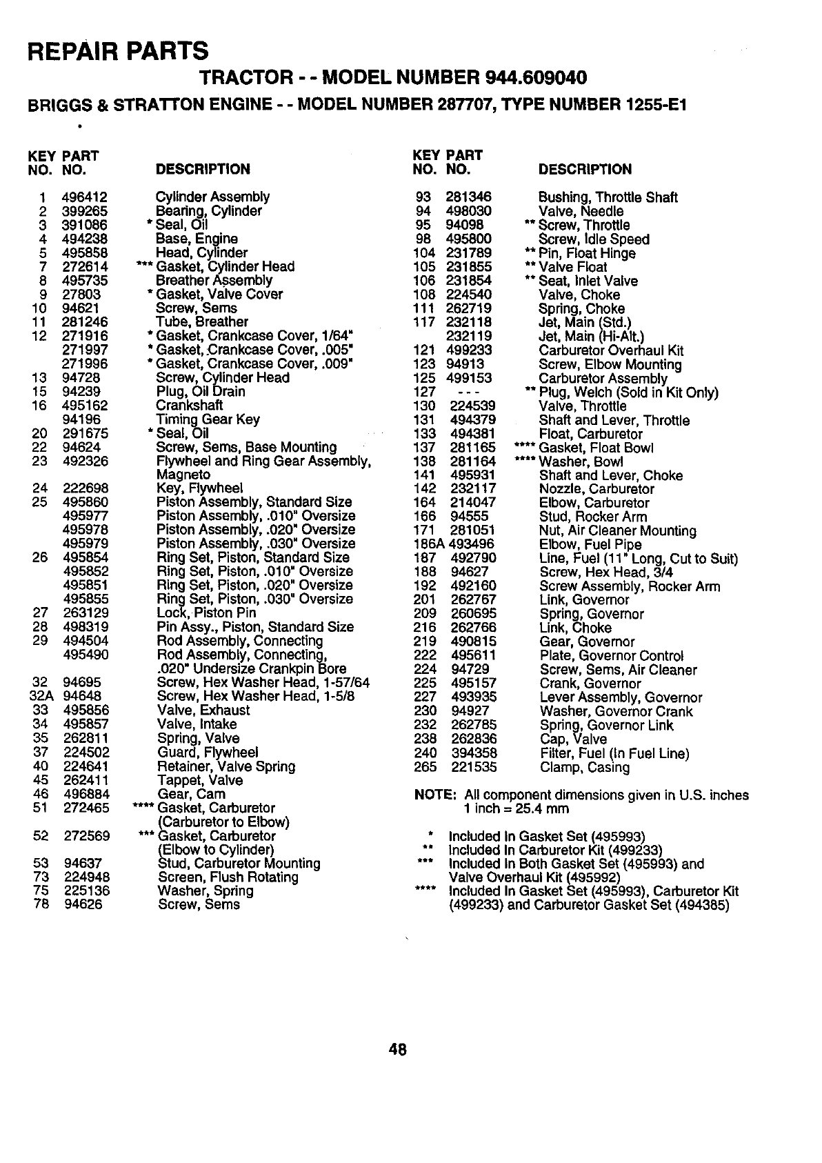
REPAIR PARTS
TRACTOR --MODEL NUMBER 944.609040
BRIGGS & STRATrON ENGINE --MODEL NUMBER 287707, TYPE NUMBER 1255-E1
KEY PART KEY PART
NO. NO. DESCRIPTION NO. NO. DESCRIPTION
1496412
2 399265
3 391086
4 494238
5495858
7 272614
8495735
9 27803
10 94621
11 281246
12 271916
271997
271996
13 94728
15 94239
16 495162
94196
20 291675
22 94624
23 492326
24 222698
25 495860
495977
495978
495979
26 495854
495852
495851
495855
27 263129
28 498319
29 494504
495490
32 94695
32A 94648
33 495856
34 495857
35 262811
37 224502
40 224641
45 262411
46 496884
51 272465
52 272569
53 94637
73 224948
75 225136
78 94626
BCylinderAssembly 93 281346
earing, Cylinder 94 498030
* Seal, Oil 95 94098
Base, Engine 98 495800
Head, Cylinder 104 231789
*** Gasket, Cylinder Head 105 231855
Breather Assembly 106 231854
* Gasket, Valve Cover 108 224540
Screw, Sems 111 262719
Tube, Breather 117 232118
* Gasket, Crankcase Cover, 1/64" 232119
* Gasket, .Crankcase Cover, .005" 121 499233
* Gasket, Crankcase Cover, .009" 123 94913
Screw, Cylinder Head 125 499153
Plug, Oil Drain 127 ---
Crankshaft 130 224539
Timing Gear Key 131 494379
* Seal, Oil 133 494381
Screw, Seres, Base Mounting 137 281165
Flywheel and Ring Gear Assembly, 138 281164
Magneto 141 495931
Key, Flywheel 142 232117
Piston Assembly, Standard Size 164 214047
Piston Assembly, .010" Oversize 166 94555
Piston Assembly, .020" Oversize 171 281051
Piston Assembly, .030" Oversize 186A 493496
Ring Set, Piston, Standard Size 187 492790
Ring Set, Piston, .010" Oversize 188 94627
Ring Set, Piston, .020" Oversize 192 492160
Ring Set, Piston, .030" Oversize 201 262767
Lock, Piston Pin 209 260695
Pin Assy., Piston, Standard Size 216 262766
Rod Assembly, Connecting 219 490815
Rod Assembly, Connecting, 222 495611
.020" Undersize Crankpin Bore 224 94729
Screw, Hex Washer Head, 1-57/64 225 495157
Screw, Hex Washer Head, 1-5/8 227 493935
Valve, Exhaust 230 94927
Valve, Intake 232 262785
Spring, Valve 238 262836
Guard, Flywheel 240 394358
Retainer, Valve Spring 265 221535
Tappet, Valve
Gear, Cam
.... Gasket, Carburetor
(Carburetor to Elbow)
*** Gasket, Carburetor
(Elbow to Cylinder)
Stud, Carburetor Mounting
Screen, Flush Rotating
Washer, Spring
Screw, Sems
Bushing, Throttle Shaft
Valve, Needle
** Screw, Throttle
Screw, Idle Speed
** Pin, Float Hinge
** Valve Float
** Seat, Inlet Valve
Valve, Choke
Spring, Choke
Jet, Main (Std.)
Jet, Main (Hi-AIt.)
Carburetor Overhaul Kit
Screw, Elbow Mounting
Carburetor Assembly
** Plug, Welch (Sold in Kit Only)
Valve, Throttte
Shaft and Lever, Throttle
Float, Carburetor
.... Gasket, Float Bowl
.... Washer, Bowl
Shaft and Lever, Choke
Nozzle, Carburetor
Elbow, Carburetor
Stud, Rocker Arm
Nut, Air Cleaner Mounting
Elbow, Fuel Pipe
Line, Fuel (11" Long, Cut to Suit)
Screw, Hex Head, 314
Screw Assembly, Rocker Arm
Link, Governor
Spring, Governor
Link, Choke
Gear, Governor
Plate, Governor Control
Screw, Sems, Air Cleaner
Crank, Governor
Lever Assembly, Governor
Washer, Governor Crank
Spring, Governor Link
Cap, Valve
Filter, Fuel (In Fuel Line)
Clamp, Casing
NOTE: All component dimensions given in U.S. inches
1 inch = 25.4 mm
*Included In Gasket Set (495993)
** Included In Carburetor Kit (499233)
*** Included In Both Gasket Set (495993) and
Valve Overhaul Kit (495992)
.... Included In Gasket Set (495993), Carburetor Kit
(499233) and Carburetor Gasket Set (494385)
48
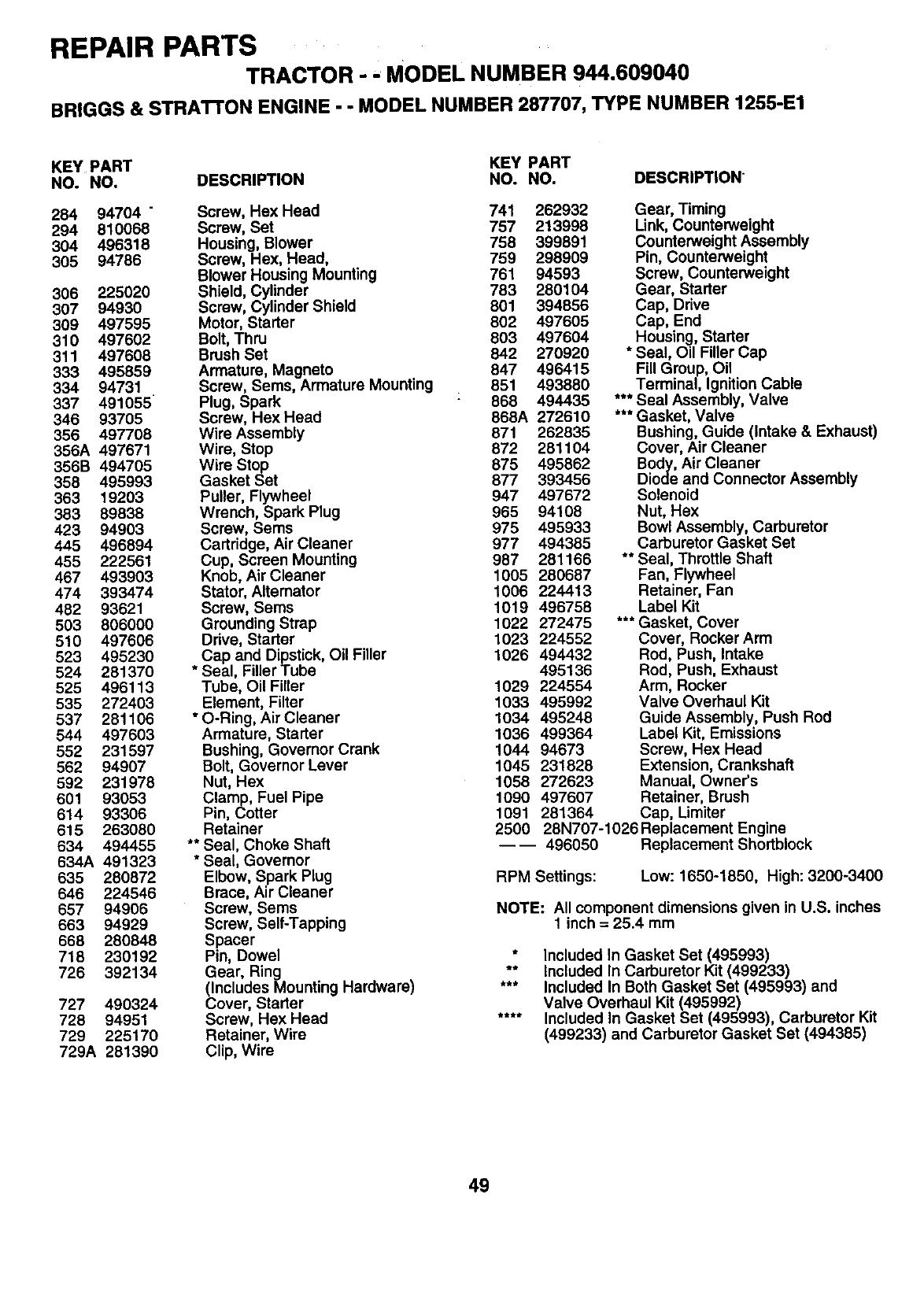
REPAIR PARTSTRACTOR - - MODEL NUMBER 944.609040
BRIGGS & STRATrON ENGINE - - MODEL NUMBER 287707, TYPE NUMBER 1255-E1
KEY PART KEY PART
NO. NO. DESCRIPTION NO. NO. DESCRIPTION"
284 94704 " Screw, Hex Head 741 262932
294 810068 Screw, Set 757 213998
304 496318 Housing, Blower 758 399891
305 94786 Screw, Hex, Head, 759 298909
Blower Housing Mounting 761 94593
306 225020 Shield, Cylinder 783 280104
307 94930 Screw, Cylinder Shield 801 394856
309 497595 Motor, Starter 802 497605
310 497602 Bolt, Thru 803 497604
311 497608 Brush Set 842 270920
333 495859 Armature Magneto 847 496415
334 94731 Screw, Sems, Armature Mount ng 851 493880
337 491055 Plug, Spark : 868 494435
346 93705 Screw, Hex Head 868A 272610
356 497708 Wire Assembly 871 262835
356A 497671 Wire, Stop 872 281104
356B 494705 Wire Stop 875 495862
358 495993 Gasket Set 877 393456
363 19203 Puller, Flywheel 947 497672
383 89838 Wrench, Spark Plug 965 94108
423 94903 Screw, Seres 975 495933
445 496894 Cartridge, Air Cleaner 977 494385
455 222561 Cup, Screen Mounting 987 281166
467 493903 Knob, AirCleaner 1005 280687
474 393474 Stator, Alternator 1006 224413
482 93621 Screw, Sems 1019 496758
503 806000 Grounding Strap 1022 272475
510 497606 Drive, Starter 1023 224552
523 495230 Cap and Dipstick, Oil Filler 1026 494432
524 281370 * Seal, Filler Tube 495136
525 496113 Tube, Oil Filler 1029 224554
535 272403 Element, Filter 1033 495992
537 281106 * O-Ring, Air Cleaner 1034 495248
544 497603 Armature, Starter 1036 499364
552 231597 Bushing, Governor Crank 1044 94673
562 94907 Bolt, Governor Lever 1045 231828
592 231978 Nut, Hex 1058 272623
601 93053 Clamp, Fuel Pipe 1090 497607
614 93306 Pin, Cotter 1091 281364
615 263080 Retainer 2500
634 494455 ** Seal, Choke Shaft
634A 491323 *Seal, Governor
635 280872 Elbow, Spark Plug
646 224546 Brace, Air Cleaner
657 94906 Screw, Sems
663 94929 Screw, Self-Tapping
668 280848 Spacer
718 230192 Pin, Dowel
726 392134 Gear, Ring
(Includes Mounting Hardware)
727 490324 Cover, Starter
728 94951 Screw, Hex Head
729 225170 Retainer, Wire
729A 281390 Clip, Wire
Gear, Timing
Link, Counterweight
Counterweight Assembly
Pin, Counterweight
Screw, Counterweight
Gear, Starter
Cap, Drive
Cap, End
Housing, Starter
* Seal, Oil Filler Cap
Fill Group, Oil
Terminal, Ignition Cable
*** Seal Assembly, Valve
*** Gasket, Valve
Bushing, Guide (Intake & Exhaust)
Cover, Air Cleaner
Body, Air Cleaner
Diode and Connector Assembly
Solenoid
Nut, Hex
Bowl Assembly, Carburetor
Carburetor Gasket Set
** Seal, Throttle Shaft
Fan, Flywheel
Retainer, Fan
Label Kit
*** Gasket, Cover
Cover, Rocker Arm
Rod, Push, Intake
Rod, Push, Exhaust
Arm, Rocker
Valve Overhaul Kit
Guide Assembly, Push Rod
Label Kit, Emissions
Screw, Hex Head
Extension, Crankshaft
Manual, Owner's
Retainer, Brush
Cap, Limiter
28N707-1026 Replacement Engine
---- 496050 Replacement Shortblock
RPM Settings: Low: 1650-1850, High: 3200-3400
NOTE: All component dimensions given in U.S. inches
1 inch = 25.4 mm
*Included In Gasket Set (495993)
** Included In Carburetor Kit (499233)
*** Included In Both Gasket Set (495993) and
Valve Overhaul Kit (495992)
.... Included In Gasket Set (495993), Carburetor Kit
(499233) and Carburetor Gasket Set (494385)
49

ii
SERVICE NOTES
50

SUGGESTED GUIDE FOR SIGHTING SLOPES FOR SAFE OPERATION
I""
SIGHTING "" _. _CUT
GUIDE TH"_
ONLY RIDE UP AND DOWN HILL,
NOT ACROSS HILL
SIGHT AND HOLD THIS LEVEL WITH
SKY LINE OR TREE.
15° MAX.
I
Operate your Tractor up and down the face of slopes (not I
greater than 15°), never across the face. Make turns gradu- I
ally to prevent tipping or !oss of control. Exercise extreme
caution when changing dtrection on slopes.
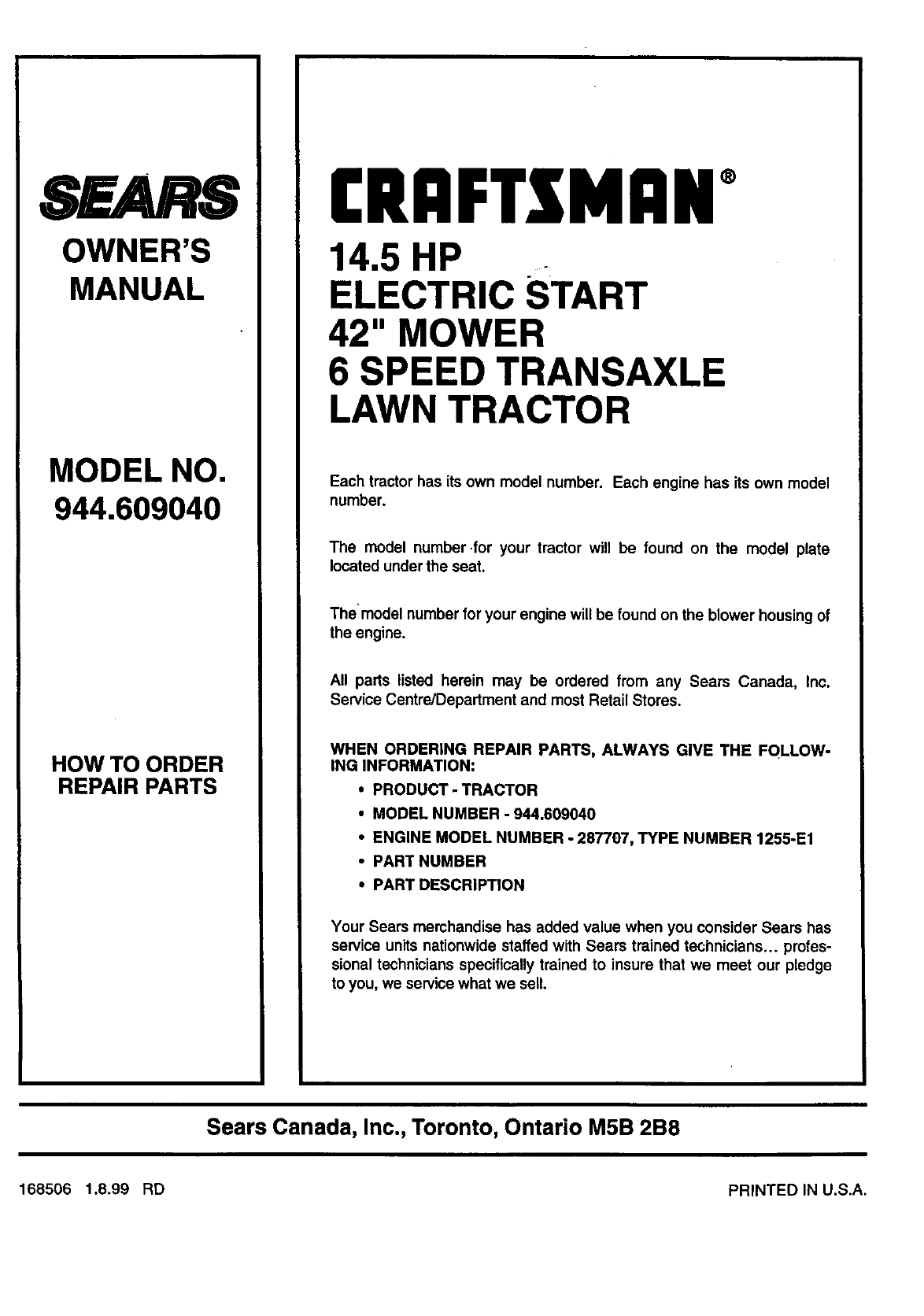
SEARS
OWNER'S
MANUAL
MODEL NO,
944.609040
HOW TO ORDER
REPAIR PARTS
[RgFTSNRN°
14.5 HP
ELECTRIC START
42" MOWER
6 SPEED TRANSAXLE
LAWN TRACTOR
Each tractor has its own model number. Each engine has its own model
number.
The model number .for your tractor will be found on the model plate
located under the seat.
The model number for your engine will be found on the blower housing of
the engine.
All parts listed herein may be ordered from any Sears Canada, Inc.
Service Centre/Department and most Retail Stores.
WHEN ORDERING REPAIR PARTS, ALWAYS GIVE THE FQLLOW-
ING INFORMATION:
•PRODUCT - TRACTOR
•MODEL NUMBER -944.609040
•ENGINE MODEL NUMBER -287707, TYPE NUMBER 1255-E1
•PART NUMBER
•PART DESCRIPTION
Your Sears merchandise has added value when you consider Sears has
service units nationwide staffed with Sears trained technicians.., profes-
sional technicians specifically trained to insure that we meet our pledge
to you, we service what we sell.
Sears Canada, Inc., Toronto, Ontario M5B 2B8
168506 1.8.99 RD PRINTED IN U.S.A.
