CRAFTSMAN Front Tine, Gas Tiller Manual 99030715
User Manual: CRAFTSMAN CRAFTSMAN Front Tine, Gas Tiller Manual CRAFTSMAN Front Tine, Gas Tiller Owner's Manual, CRAFTSMAN Front Tine, Gas Tiller installation guides
Open the PDF directly: View PDF ![]() .
.
Page Count: 30
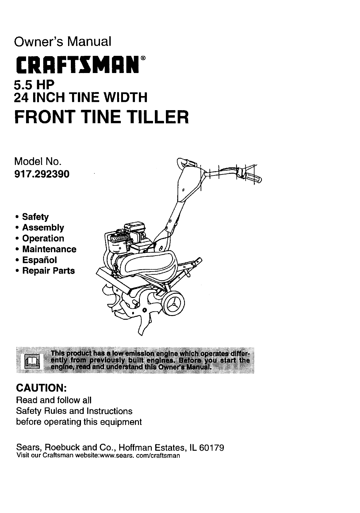
Owner's Manual
rRnFTSMRNo
5.5 HP
24 INCH TINE WIDTH
FRONT TINE TILLER
Model No.
917.292390
• Safety
• Assembly
• Operation
•Maintenance
•Espa_ol
• Repair Parts
CAUTION:
Read and follow all
Safety Rules and Instructions
before operating this equipment
Sears, Roebuck and Co., Hoffman Estates, IL 60179
Visit our Craftsman website:www.sears, com/craftsman
Warranty ................................................. 2
Safety Rules ........................................... 2
Product Specifications .......................... 4
Assembly ................................................ 6
Operation ......................................... 3 & 7
Maintenance ......................................... 11
Service and Adjustments ...................... 13
Storage ...................... :................... 3 & 16
Troubleshooting .................................... 17
Illustrated Parts List .............................. 37
Parts Ordering ....................... Back Cover
LIMITED ONE YEAR WARRANTY ON CRAFTSMAN TILLER
For one (1) year from date of purchase, when this Craftsman Tiller is maintained, lubri-
cated, and tuned up according to the operating and maintenance instructions in the
owner's manual, Sears will repair free of charge any defect in material or workmanship.
This Warranty does not cover:
•Expendable items which become worn during normal use, such as tines, spark plugs,
air cleaners and belts.
•Repairs necessary because of operator abuse or negligence, including bent crank-
shafts and the failure to maintain the equipment according to the instructions con-
tained in the owner's manual.
•If this Craftsman Tiller is used for commercial or rental purposes, this Warranty
applies for only thirty (30) days from the date of purchase.
Warranty service is available by returning the Craftsman Tiller to the nearest Sears ser-
vice center/department in the United States. This warranty applies only while this prod-
uct is in use in the United States.
This Warranty gives you specific legal rights, and you may also have other rights which
vary from state to state.
SEARS, ROEBUCK AND CO., D/817WA, HOFFMAN ESTATES, IL 60179
TRAINING
•Read the Owner's Manual carefully. Be
thoroughly familiar with the controls and
the proper use of the equipment. Know
how to stop the unit and disengage the
controls quickly.
•Never allow children to operate the
equipment. Never allow adults to oper-
ate the equipment without proper
instruction.
•Keep the area of operation clear of all
persons, particularly small children, and
pets.
PREPARATION
•Thoroughly inspect the area where the
equipment is to be used and remove all
foreign objects.
•Disengage all clutches and shift into
neutral before starting the engine (mo-
tor).
•Do not operate the equipment without
wearing adequate outer garments. Wear
footwear that will improve footing on
slippery surfaces.
•Handle fuel with care; it is highly flam-
mable.
•Use an approved fuel container.
•Never add fuel to a running engine or
hot engine.
•Fill fuel tank outdoors with extreme
care. Never fill fuel tank indoors.
•Replace gasoline cap securely and
clean up spilled fuel before restarting.
•Use extension cords and receptacles as
specified by the manufacturer for all
units with electric drive motors or elec-
tric starting motors.
•Never attempt to make any adjustments
while the engine (motor) is running
(except where specifically recommend-
ed by manufacturer).
2
OPERATION
•Do not put hands or feet near or under
rotating pads.
•Exercise extreme caution when operat-
ing on or crossing gravel drives, walks,
or roads. Stay alert for hidden hazards
or traffic. Do not carry passengers.
•After striking a foreign object, stop the
engine (motor), remove the wire from
the spark plug, thoroughly inspect the
tiller for any damage, and repair the
damage before restarting and operating
the tiller.
• Exercise caution to avoid slipping or
falling.
• If the unit should start to vibrate abnor-
mally, stop the engine (motor) and check
immediately for the cause. Vibration is
generally a warning of trouble.
• Stop the engine (motor) when leaving
the operating position.
• Take all possible precautions when leav-
ing the machine unattended. Disengage
the tines, shift into neutral, and stop the
engine.
• Before cleaning, repairing, or inspecting,
shut off the engine and make certain all
moving parts have stopped. Disconnect
the spark plug wire, and keep the wire
away from the plug to prevent accidental
starting. Disconnect the cord on electric
motors.
• Do not run the engine indoors; exhaust
fumes are dangerous.
• Never operate the tiller without proper
guards, plates, or other safety protective
devices in place.
• Keep children and pets away.
• Do not overload the machine capacity
by attempting to till too deep at too fast a
rate.
• Never operate the machine at high
speeds on slippery surfaces. Look
behind and use care when backing.
• Never allow bystanders near the unit.
• Use only attachments and accessories
approved by the manufacturer of the
tiller.
• Never operate the tiller without good vis-
ibility or light.
•Be careful when tilling in hard ground.
The tines may catch in the ground and
propel the tiller forward. If this occurs,
let go of the handlebars and do not
restrain the machine.
MAINTENANCE AND STORAGE
•Keep machine, attachments, and
accessories in safe working condition.
•Check shear p_ns, engine mounting
bolts, and other bolts at frequent inter-
vals for proper tightness to be sure the
equipment is in safe working condition.
•Never store the machine with fuel in the
fuel tank inside a building where ignition
sources are present, such as hot water
and space heaters, clothes dryers, and
the like. Allow the engine to cool before
storing in any enclosure.
•Always refer to the operator's guide
instructions for important details if the
tiller is to be stored for an extended peri-
od.
_CAUTION: Always disconnect spark
plug wire and place wire where it cannot
contact spark plug in order to prevent acci-
dental starting when setting up, transport-
ing, adjusting or making repairs.
WARNING: The engine exhuast from this
product contains chemicals known to the
State of Catifomia to cause cancer, birth
defectd, or other reproductive harm.
3

PRODUCT SPECIRCAllONS
HORSEPOWER: 5.5 HP
)ISPLACEMENT: 13 CU. IN.
(221CC)
;ASOLINE CAPACITY: 4 Quads
Unleaded Regular
JIL (API-SF/SG/SH): SAE 30
(Above 32°F)
CAPACITY: 20 oz.) SAE 5W-30
(Below 32°F)
_PARK PLUG : Champion RJ19LM
GAP: .030") or J19LM
Congratulations on your purchase of a
Sears Tiller. It has been designed, engi-
neered and manufactured to give you the
best possible dependability and perform-
ance.
Should you experience any problems you
cannot easily remedy, pleas e contact your
nearest authorized Sears Service
Center/Department. We have competent,
well-trained technicians and the proper
tools to service or repair this unit.
Please read and retain this manual. The
instructions will enable you to assemble
and maintainyour tiller proper_. Always
observe the SAFETY RULES.
Your new tiller has been assembled at the
factory with exception of those parts left
unassembted for shipping purposes. To
ensure safe and proper operation of your
tiller all parts and hardware you assemble
must be tightened securely. Use the cor-
rect tools as necessary to insure proper
tightness.
MAINTENANCE AGREEMENT
A Sears Maintenance Agreement is avail-
able on this product. Contact your nearest
Sears store for details.
CUSTOMER RESPONSIBILITIES
•Read and observe the safety rules.
•Follow a regular schedule in maintain-
ing, caring for and using your tiller.
•Follow the instructions under the
"Maintenance" and "Storage" sections of
this Owner's Manual.
WARNING: This unit is equipped with an
internal combustion engine and should not
be used on or near any unimproved forest-
covered, brush-covered or grass covered
land unless the engine's exhaust system is
equipped with a spark arrester meeting
applicable local or state laws (if any). If a
spark arrester is used, it should be main-
tained in effective working order by the
operator.
In the state of California the above is
required by law (Section 4442 of the
California Public Resources Code). Other
states may have similar laws. Federal
laws apply on federal lands. See your
Sears Authorized Service Center for spark
arrester. Refer to the Repair Parts section
of this manual for part number.
These accessories were available when the tiller was purchased. They are also avail-
able at most Sears Retail outlets and Service Centers. Most Sears Stores can order
repair parts for you when you provide the model number of your tiller.
ENGINE
TILLER MAINTENANCE
BELT TINES SHEAR PIN HAIRPIN CLIP
4
Your new tiller has been assembled at the
factory with exception of those parts left
unassembled for shipping purposes. To
ensure safe and proper operation of your
tillre all parts and hardware you assemble
must be tightened securely. Use the correct
tools as necessary to insure proper tight-
Bess.
TOOLS REQUIRED FOR ASSEMBLY
A socket wrench set will make assembly
easier. Standard wrench sizes are listed.
(1) Utility knife
(1) Pair of pliers
(2) 1/2" wrenches
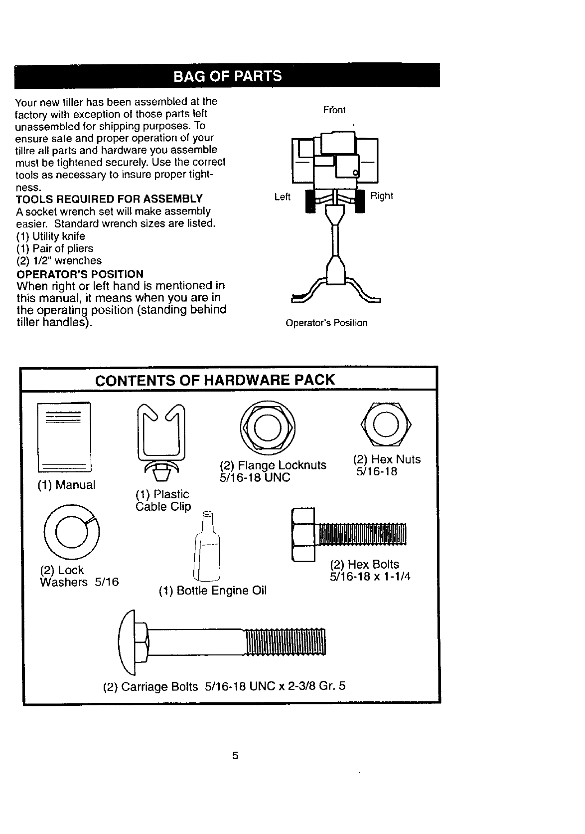
OPERATOR'S POSITION
When right or left hand is mentioned in
this manual, it means when you are in
the operating position (standing behind
tiller handles).
FFont
Left_' ht
Operator's Position
CONTENTS OF HARDWARE PACK
(1) Manual
(2) Lock
Washers 5/16
G
(2) Flange Locknuts
5/16-18 UNC
©
(2) Hex Nuts
5/16-18
(1) Plastic
Cable Clip
(2) Hex Bolts
5/16-18 x 1-1/4
(1) Bottle Engine Oil
(2) Carriage Bolts 5/16-18 UNC x 2-3/8 Gr. 5
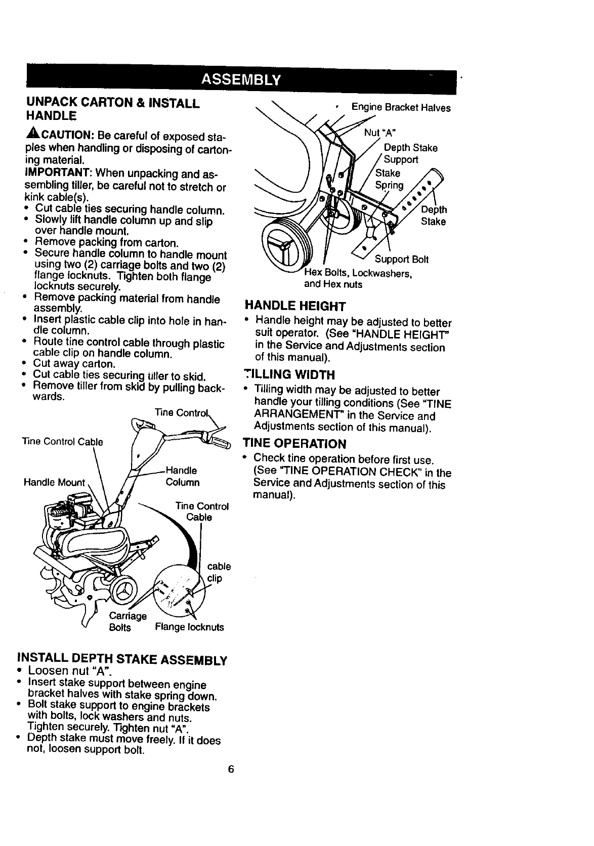
UNPACK CARTON & INSTALL
HANDLE
,_CAUTION: Be careful of exposed sta-
ples when handling or disposing of carton-
ing material.
IMPORTANT: When unpacking and as-
sembling tiller, be careful not to stretch or
kink cable(s).
• Cut cable ties securing handle column.
•Slowly lift handle column up and slip
over handle mount,
•Remove packing from carton.
•Secure handle column to handle mount
using two (2) carriage bolts and two (2)
flange Iocknuts. Tighten both flange
Iocknuts securely.
•Remove packing material from handle
assembly.
•Insert plastic cable clip into hole in han-
dle column.
• Route tine control cable through plastic
cable clip on handle column.
• Cut away carton.
Cut cable ties securing tiller to skid.
•_ Remove tiller from skid by pulling back-
wards.
"line Control Cable
Handle Mount, Column
lineControl
Cable
\Engine Bracket Halves
Nut =A"
Depth Stake
Stake
Support Bolt
Lockwashers,
and Hex nuts
HANDLE HEIGHT
• Handle height may be adjusted to better
suit operator. (See "HANDLE HEIGHT"
in the Service and Adjustments section
of this manual).
TILLING WIDTH
•Tilling width may be adjusted to better
handle your tilling conditions (See "TINE
ARRANGEMENT" in the Service and
Adjustments section of this manual).
TINE OPERATION
•Check tine operation before first use.
(See "FINE OPERATION CHECK" in the
Service and Adjustments section of this
manual).
cable
clip
Carriage
Bolts Flange Iocknuts
INSTALL DEPTH STAKE ASSEMBLY
•Loosen nut "A".
• Insert stake support between engine
bracket halves with stake spring down.
• Bolt stake support to engine brackets
with bolts, lock washers and nuts.
Tighten securely. Tighten nut "A".
•Depth stake must move freely. If it does
not, loosen support bolt.
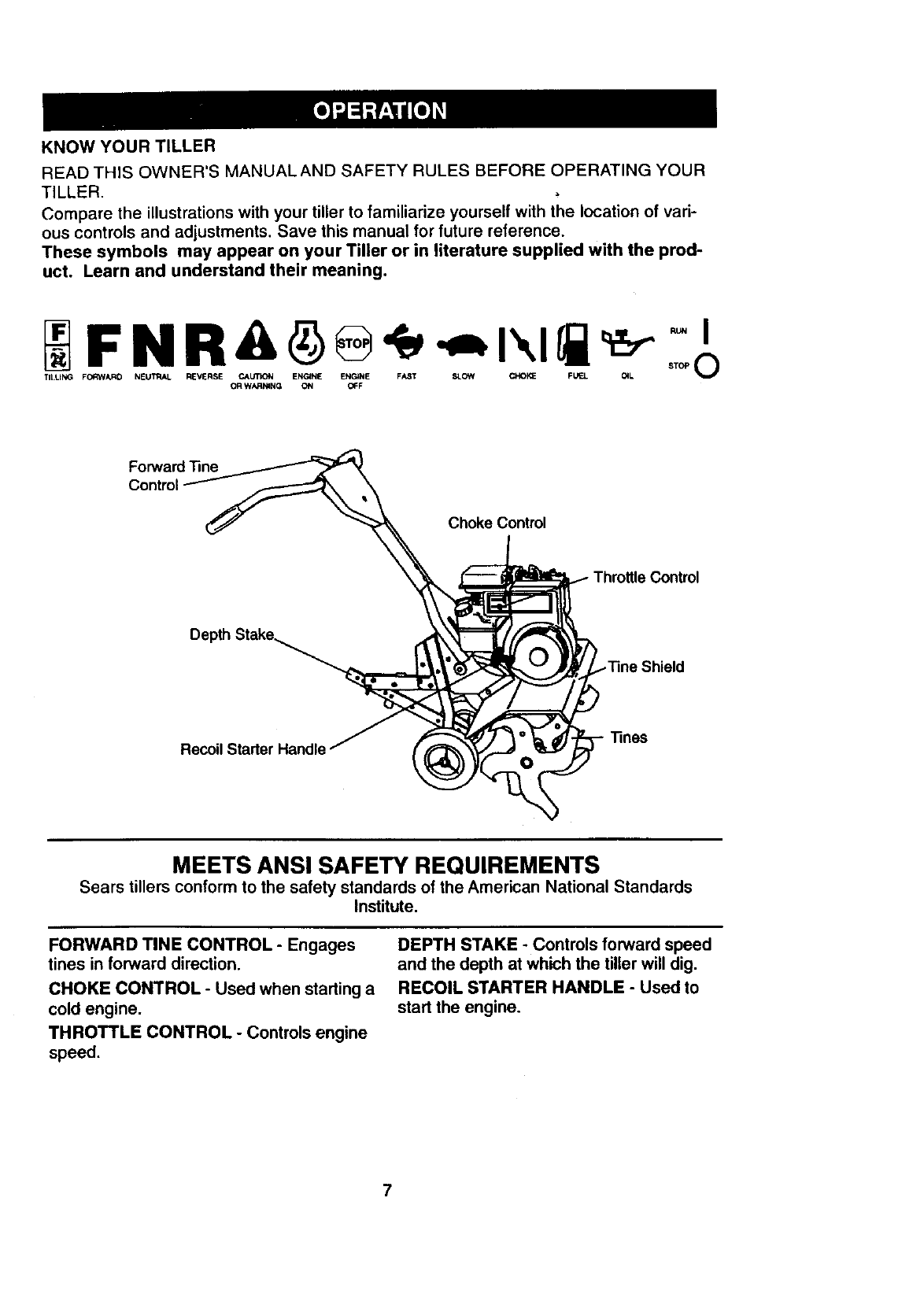
KNOW YOUR TILLER
READ THIS OWNER'S MANUALAND SAFETY RULES BEFORE OPERATING YOUR
TILLER.
Compare the illustrations with your tiller to familiarize yourself with the location of vari-
ous controls and adjustments. Save this manual for future reference.
These symbols may appear on your Tiller or in literature supplied with the prod-
uct. Learn and understand their meaning.
TILLING FORWARD NEUTRAL REVERSE CAUTION ENGINE ENGINE FAST SLOW ChX)KE FU_L 01L
OR WARk_NG ON _F
Forward Tine
Choke Control
Throttle Control
Recoil
MEETS ANSI SAFETY REQUIREMENTS
Sears tillers conform to the safety standards of the American National Standards
Institute,
FORWARD TINE CONTROL - Engages
tines in forward direction.
CHOKE CONTROL - Used when starting a
cold engine.
THROTTLE CONTROL -Controls engine
speed.
DEPTH STAKE - Controls forward speed
and the depth at which the tiller will dig.
RECOIL STARTER HANDLE - Used to
start the engine.
7
Theoperationof anytiller canresultinforeign objects thrown into the eyes,
which can result in Severe eye damage. Always wear safety glasses or eye
shields before starting your tiller and while tilling. We recommend a wide vision
safety mask over spectacles or standard safety glasses.
HOW TO USE YOUR TILLER
Know how to operate al_controls before
adding fuel and oil or attempting to start
engine.
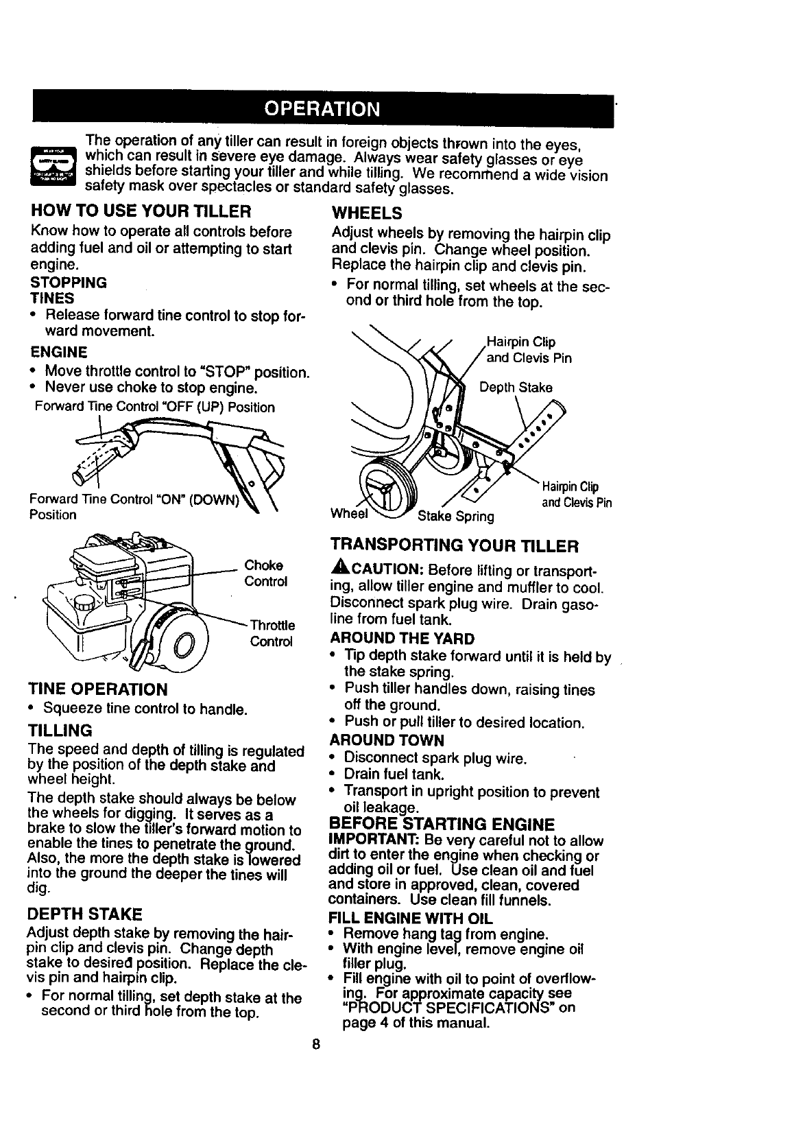
STOPPING
TINES
•Release forward tine control to stop for-
ward movement.
ENGINE
• Move throttle control to "STOP" position.
•Never use choke to stop engine.
WHEELS
Adjust wheels by removing the hairpin clip
and clevis pin. Change wheel position.
Replace the hairpin clip and clevis pin.
• For normal tilling, set wheels at the sec-
ond or third hole from the top.
\Hairpin Clip
Depth Stake
Forward "nne Control "OFF (UP) Position
Forward "nne Control "ON" (DOW_
Position
Choke
Control
Control
TINE OPERATION
•Squeeze tine control to handle.
TILLING
The speed and depth of tilling is regulated
by the position of the depth stake and
wheel height.
The depth stake should always be below
the wheels for digging. It serves as a
brake to slow the titler's forward motion to
enable the tines to penetrate the ground.
Also, the more the depth stake is lowered
into the ground the deeper the tines will
dig.
DEPTH STAKE
Adjust depth stake by removing the hair-
pin clip and clevis pin. Change depth
stake to desired position. Replace the cle-
vis pin and hairpin clip.
• For normal tilling, set depth stake at the
second or third hole from the top.
lairpinClip
andClevisPin
Wh Stake Spring
TRANSPORTING YOUR TILLER
,ACAUTION: Before lifting or transport-
ing, allow tiller engine and muffler to cool.
Disconnect spark plug wire. Drain gaso-
line from fuel tank.
AROUND THE YARD
•Tip depth stake forward until it is held by
the stake spring.
•Push tiller handles down, raising tines
off the ground.
•Push or pull tiller to desired location.
AROUND TOWN
•Disconnect spark plug wire.
•Drain fuel tank.
•Transport in upright position to prevent
oil leakage.
BEFORE STARTING ENGINE
IMPORTANT: Be very careful not to allow
dirt to enter the engine when checking or
adding oil or fuel. Use clean oil and fuel
and store in approved, clean, covered
containers. Use clean fill funnels.
FILL ENGINE WITH OIL
Remove hang tag from engine.
With engine level, remove engine oil
filler plug.
•Fill engine with oil to point of overflow-
ing. For approximate capacity see
=PRODUCT SPECIFICATIONS" on
page 4 of this manual.
8
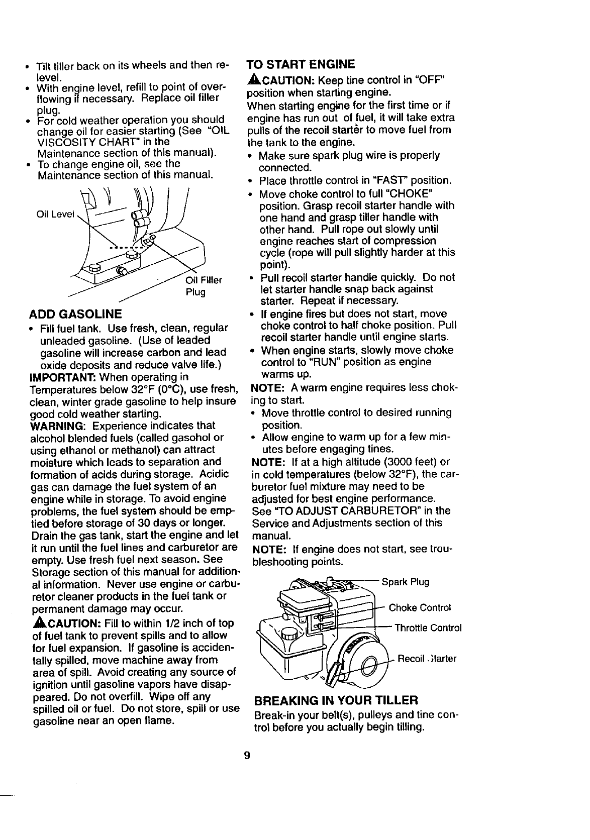
• Tilt tiller back on its wheels and then re-
level.
•With engine level, refill to point of over-
flowing if necessary. Replace oil filler
plug.
•For cold weather operation you should
change oil for easier starting (See "OIL
VISCOSITY CHART" in the
Maintenance section of this manual).
• To change engine oil, see the
Maintenance section of this manual.
Oil Level,
ADD GASOLINE
•Fill fuel tank. Use fresh, clean, regular
unleaded gasoline. (Use of leaded
gasoline will increase carbon and lead
oxide deposits and reduce valve life.)
IMPORTANT: When operating in
Temperatures below 32°F (0°C), use fresh,
clean, winter grade gasoline to help insure
good cold weather starting.
WARNING: Experience indicates that
alcohol blended fuels (called gasohol or
using ethanol or methanol) can attract
moisture which leads to separation and
formation of acids during storage. Acidic
gas can damage the fuel system of an
engine while in storage. To avoid engine
problems, the fuel system should be emp-
tied before storage of 30 days or longer.
Drain the gas tank, start the engine and let
it run until the fuel lines and carburetor are
empty. Use fresh fuel next season. See
Storage section of this manual for addition-
al information. Never use engine or carbu-
retor cleaner products in the fuel tank or
permanent damage may occur.
_,CAUTION: Fill to within 1/2 inch of top
of fuel tank to prevent spills and to allow
for fuel expansion. If gasoline is acciden-
tally spilled, move machine away from
area of spill Avoid creating any source of
ignition until gasoline vapors have disap-
peared. Do not overfill. Wipe off any
spilled oil or fuel. Do not store, spill or use
gasoline near an open flame.
TO START ENGINE
_CAUTION: Keep line control in "OFF"
position when starting engine.
When starting engine for the first time or if
engine has run out of fuel, it will take extra
pulls of the recoil starter to move fuel from
the tank to the engine.
•Make sure spark plug wire is properly
connected.
•Place throttle control in "FAST" position.
•Move choke control to full "CHOKE"
position. Grasp recoil starter handle with
one hand and grasp tiller handle with
other hand. Pull rope out slowly until
engine reaches start of compression
cycle (rope will pull slightly harder at this
point).
• Pull recoil starter handle quickly. Do not
let starter handle snap back against
starter. Repeat if necessary.
• If engine fires but does not start, move
choke control to half choke position. Pull
recoil starter handle until engine starts.
• When engine starts, slowly move choke
control to "RUN" position as engine
warms up.
NOTE: Awarm engine requires less chok-
ing to start.
• Move throttle control to desired running
position.
• Allow engine to warm up for a few min-
utes before engaging tines.
NOTE: If at a high altitude (3000 feet) or
in cold temperatures (below 32°F), the car-
buretor fuel mixture may need to be
adjusted for best engine performance.
See "TO ADJUST CARBURETOR" in the
Service and Adjustments section of this
manual.
NOTE: If engine does not start, see trou-
bleshooting points.
Spark Plug
Choke Control
Recoil, ;tarter
BREAKING IN YOUR TILLER
Break-in your belt(s), pulleys and tine con-
trol before you actually begin tilling.
9
• Startengine,tip tinesoff groundby
pressinghandlesdownandengageline
controlto start line rotation.Allowtines
to rotatefor five minutes.
• Check tine operation and adjust if nec-
essary. See "FINE OPERATION
CHECK" in the Service and Adjustments
section of this manual.
TILLING HINTS
_CAUTION: Until you are accustomed to
handlingyour tiller,start actual field use
with throttlein slow position (mid-way be-
tween =FAST" and =IDLE").
To help tiller move forward, lift up the han-
dles slightly (thus lifting depth stake out of
ground). To slow down the tiller, press
down on handles.
If you are straining or tiller is shaking, the
wheels and depth stake are not set prop-
erly in the soil being tilled. The proper set-
ting of the wheels and depth stake is
through trial and error and depends upon
the soil condition. (The harder or wetter
the ground, the slower the engine and tine
speed needed. Under these poor condi-
tions, at fast speed the tiller will run and
jump over the ground).
A properly adjusted tiller will dig with little
effort from the operator.
•Tilling is digging into, turning over, and
breaking up packed soil before planting.
Loose, unpacked soil helps root growth.
Best tilling depth is 4" to 6". A tiller will
also clear the soil of unwanted vegeta-
tion. The decomposition of this veg-
etable matter enriches the soil.
Depending on the climate (rainfall and
wind), it may be advisable to till the soil
at the end of the growing season to fur-
ther condition the soil.
• Soil conditions are important for proper
tilling. Tines will not readily penetrate
dry, hard soil which may contribute to
excessive bounce and difficult handling
of your tiller. Hard soil should be mois-
tened before tilling; however, extremely
wet soil will "ball-up" or clump during till-
ing. Wait until the soil is less wet in order
to achieve the best results. When tilling
in the fall, remove vines and long grass
to prevent them from wrapping around
the line shaft and slowing your tilling
operation.
You will find tilling much easier if you
leave a row untilled between passes.
Then go back be,tween tilled rows.There
are two reasons for doing this. First,
wide turns are much'easier to negotiate
than about-faces. Second, the tiller
won't be pulling itself, and you, toward
the row next to it.
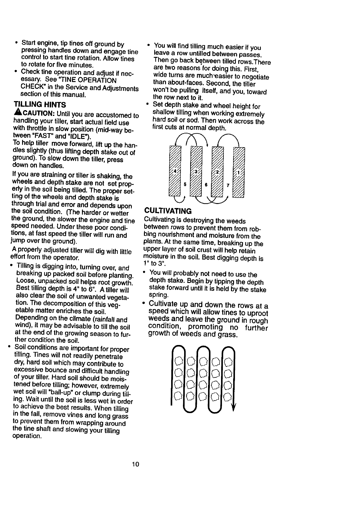
Set depth stake and wheel height for
shallow tilling when working extremely
hard soil or sod. Then work across the
first cuts at normal depth.
CULTIVATING
Cultivating is destroying the weeds
between rows to prevent them from rob-
bing nourishment and moisture from the
plants. At the same time, breaking up the
upper layer of soil crust will help retain
moisture in the soil. Best digging depth is
1" to 3".
You will probably not need to use the
depth stake. Begin by tipping the depth
stake forward until it is held by the stake
spring.
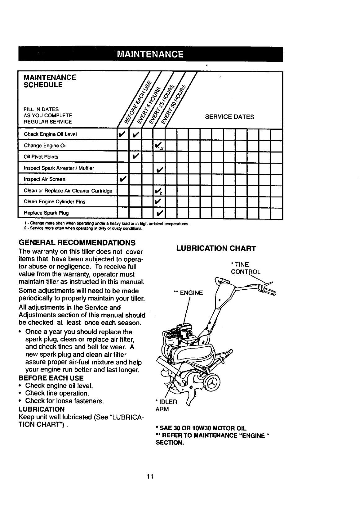
Cultivate up and down the rows at a
speed which will allow tines to uproot
weeds and leave the ground in rough
condition, promoting no further
growth of weeds and grass.
IO OIO O!O
iO OIO OIO
io OlO OlO
O OIO OIO
I
10
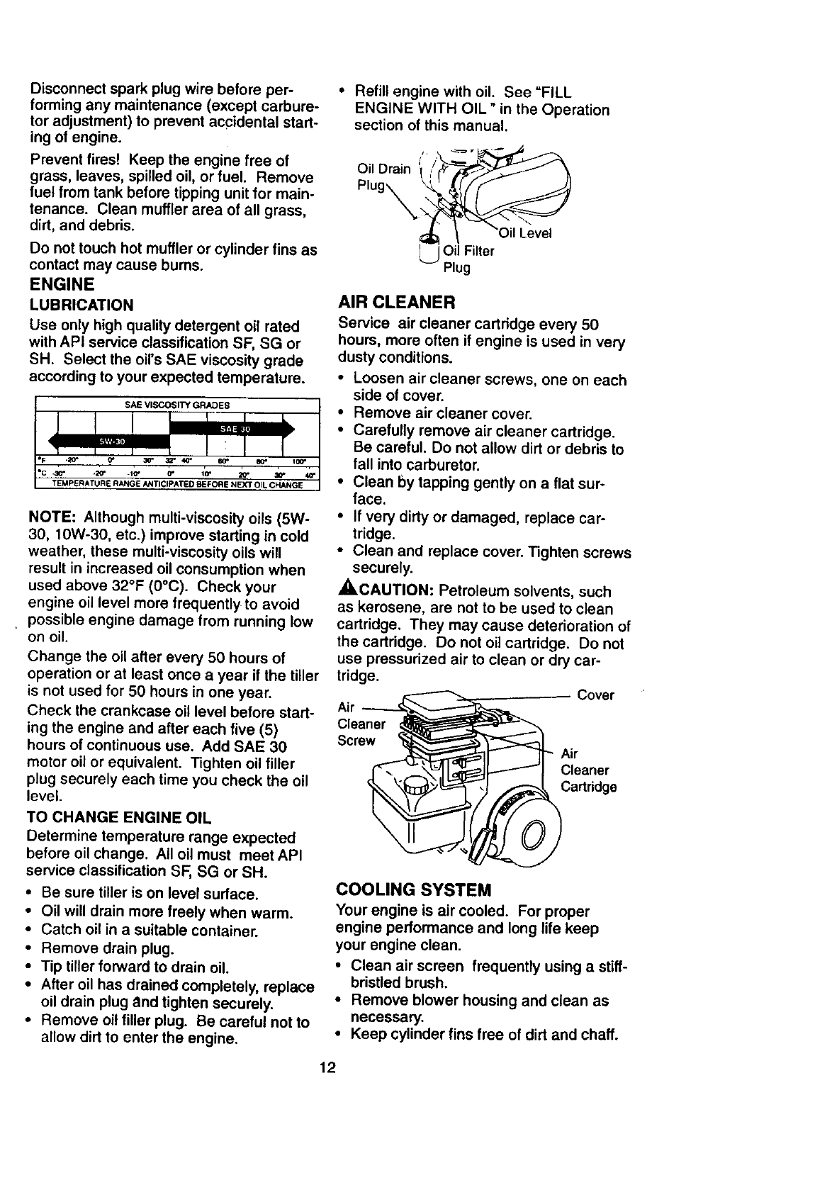
MA,N,ENANCE
SCHEDULE
, ',.OATES LO . Z SERV'CEOATES
AS YOU COMPLETE
nEOO nSE°V,CE
Check EngineOil Level _ I_
Change Engine Oil _1,2
Oil Pivot Points I_
Inspect Spark Arrester/Muffler I_
Inspect Air Screen V'
Clean or Replace Air Cleaner Cartridge i_ 2
Clean Engine Cylinder Fins b/'
Replace Spark Plug I_
1 - Change more olten when operating under a heavy lOado_ in high amblont temperatures.
2 - Service more o_en when operaUng _dirty or dusty conditions.
GENERAL RECOMMENDATIONS
The warranty on this tiller does not cover
items that have been subjected to opera-
tor abuse or negligence. To receive full
value from the warranty, operator must
maintain tiller as instructed in this manual,
Some adjustments will need to be made
periodically to propedy maintain your tiller.
All adjustments in the Service and
Adjustments section of this manual should
be checked at least once each season.
• Once a year you should replace the
spark plug, clean or replace air filter,
and check tines and belt for wear. A
new spark plug and clean air filter
assure proper air-fuel mixture and help
your engine run better and last longer.
BEFORE EACH USE
•Check engine oil level.
•Check fine operation.
•Check for loose fasteners.
LUBRICATION
Keep unit well lubricated (See "LUBRICA-
TION CHART").
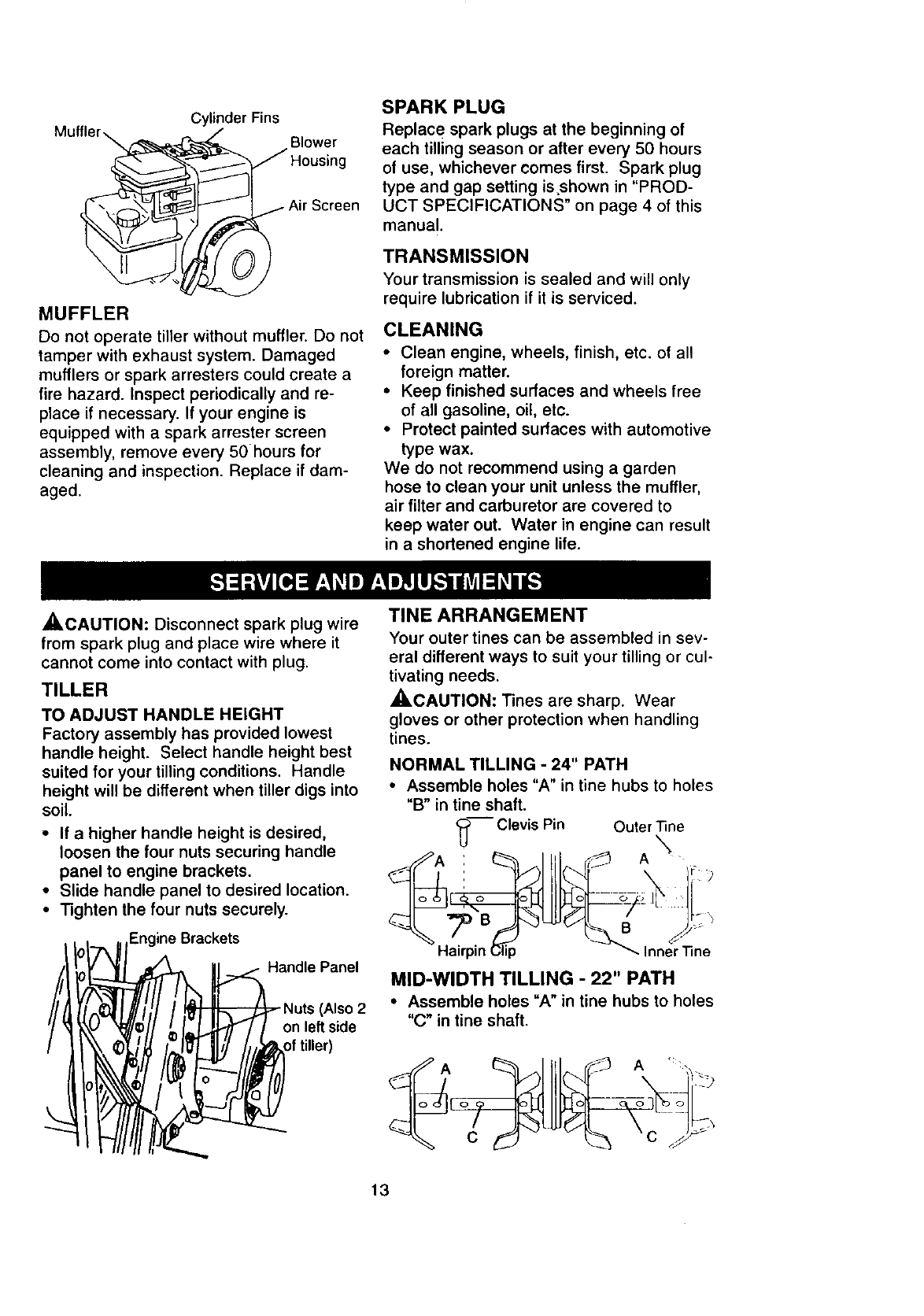
LUBRICATION CHART
* TINE
CONTROL
** ENGINE
*IDLER
ARM
• SAE 30 OR 10W30 MOTOR OIL
** REFER TO MAINTENANCE "ENGINE"
SECTION.
11
Disconnect spark plug wire before per-
forming any maintenance (except carbure-
tor adjustment) to prevent accidental start-
ing of engine.
Prevent firest Keep the engine free of
grass, leaves, spilled oil, or fuel. Remove
fuel from tank before tipping unit for main-
tenance. Clean muftler area of all grass,
dirt, and debris.
Do not touch hot muffler or cylinder fins as
contact may cause burns.
ENGINE
LUBRICATION
Use only high quality detergent oil rated
with API service classification SF, SG or
SH. Select the oil's SAE viscosity grade
according to your expected temperature.
NOTE: Although multi-viscosity oils (5W-
30, 10W-30, etc.) improve starting in cold
weather, these multi-viscosity oils will
result in increased oil consumption when
used above 32°F (0°C). Check your
engine oil level more frequently to avoid
•possible engine damage from running low
on oil.
Change the oil after every 50 hours of
operation or at least once a year if the tiller
is not used for 50 hours in one year.
Check the crankcase oil level before start-
ing the engine and after each five (5)
hours of continuous use. Add SAE 30
motor oil or equivalent. Tighten oil filler
plug securely each time you check the oil
level.
TO CHANGE ENGINE OIL
Determine temperature range expected
before oil change. All oil must meet API
service classification SF, SG or SH.
•Be sure tiller is on level surface.
• Oil will drain more freely when warm.
• Catch oil in a suitable container.
• Remove drain plug.
• Tip tiller forward to drain oil.
• After oil has drained completely, replace
oil drain plug and tighten securely.
• Remove oil filler plug. Be careful not to
allow dirt to enter the engine.
• Refill engine with oil. See =FILL
ENGINE WITH OIL" in the Operation
section of this manual.
Oil Drain
Oil Filter
Plug
AIR CLEANER
Service air cleaner cartridge every 50
hours, more often if engine is used in very
dusty conditions.
•Loosen air cleaner screws, one on each
side of cover.
• Remove air cleaner cover.
•Carefully remove air cleaner cartridge.
Be careful. Do not allow dirt or debris to
fall into carburetor.
•Clean by tapping gently on a flat sur-
face.
•If very dirty or damaged, replace car-
tridge.
•Clean and replace cover. Tighten screws
securely.
_.CAUTION: Petroleum solvents, such
as kerosene, are not to be used to clean
cartridge. They may cause deterioration of
the cartridge. Do not oil cartridge. Do not
use pressurized air to clean or dry car-
tridge.
Air
Cleaner
Screw
;over
Air
Cleaner
Cartndge
COOLING SYSTEM
Your engine is air cooled. For proper
engine performance and long life keep
your engine clean.
•Clean air screen frequently using a stiff-
bristled brush.
•Remove blower housing and clean as
necessary.
•Keep cylinder fins free of dirt and chaff.
12
Cylinder Fins
Muffler \ Blower
ig
MUFFLER
Do not operate tiller without muffler. Do not
tamper with exhaust system. Damaged
mufflers or spark arresters could create a
fire hazard. Inspect periodically and re-
place if necessary. If your engine is
equipped with a spark arrester screen
assembly, remove every 50 hours for
cleaning and inspection. Replace if dam-
aged.
SPARK PLUG
Replace spark plugs at the beginning of
each tilling season or after every 50 hours
of use, whichever comes first. Spark plug
type and gap setting isshown in "PROD-
UCT SPECIFICATIONS" on page 4 of this
manual.
TRANSMISSION
Your transmission is sealed and will only
require lubrication if it is serviced.
CLEANING
•Clean engine, wheels, finish, etc. of all
foreign matter.
• Keep finished surfaces and wheels free
of all gasoline, oil, etc.
• Protect painted surfaces with automotive
type wax.
We do not recommend using a garden
hose to clean your unit unless the muffler,
air filter and carburetor are covered to
keep water out. Water in engine can result
in a shortened engine life.
_.CAUTION: Disconnect spark plug wire
from spark plug and place wire where it
cannot come into contact with plug.
TILLER
TO ADJUST HANDLE HEIGHT
Factory assembly has provided lowest
handle height. Select handle height best
suited for your tilling conditions, Handle
height will be different when tiller digs into
soil.
• If a higher handle height is desired,
loosen the four nuts securing handle
panel to engine brackets.
•Slide handle panel to desired location.
• Tighten the four nuts securely.
II I--_ _1Engine Brackets
Handle Panel
Nuts (Also 2
on left side
of tiller)
TINEARRANGEMENT
Your outer tines can be assembled in sev-
eral different ways to suit your tilling or cul-
tivating needs.
_I, CAUTION: Tines are sharp. Wear
gloves or other protection when handling
tines.
NORMAL TILLING -24" PATH
•Assemble holes "A" in tine hubs to holes
"B" in tine shaft.
_-_- Clevis Pin Outer "nne
iA x'_
Hail
B
Inner Tine
MID-WIDTH TILLING - 22" PATH
•Assemble holes "A" in tine hubs to holes
"C" in tine shaft.
13
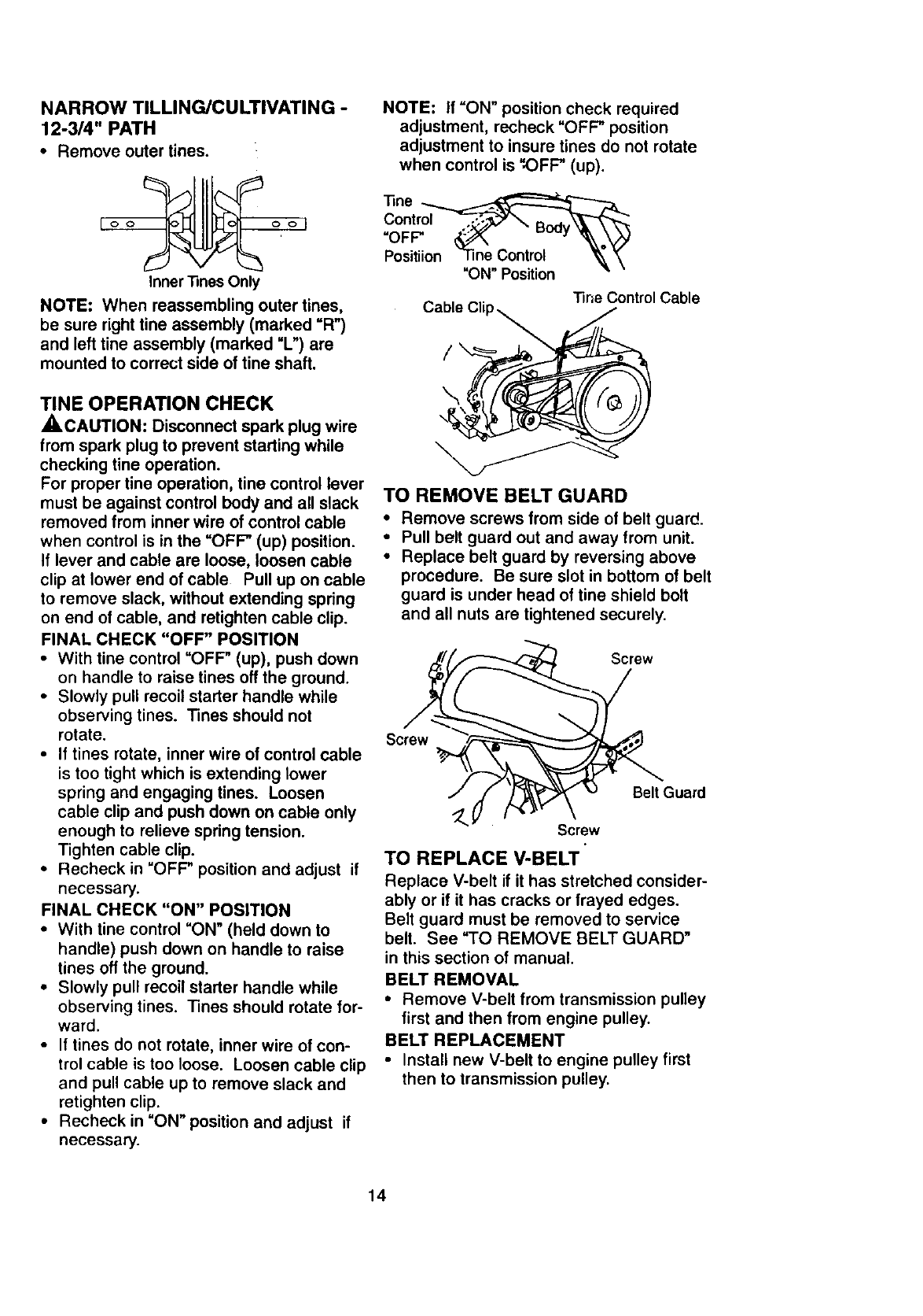
NARROW TILLING/CULTIVATING -
12-3/4" PATH
•Remove outer tines.
Inner Tines Only
NOTE: When reassembling outer tines,
be sure right fine assembly (marked =R")
and left tine assembly (marked "L") are
mounted to correct side of tine shaft.
TINE OPERATION CHECK
,_,CAUTION: Disconnect spark plug wire
from spark plug to prevent starting while
checking tine operation.
For proper fine operation, fine control lever
must be against control body and all slack
removed from inner wire of control cable
when control is in the "OFP (up) position.
If lever and cable are loose, loosen cable
clip at lower end of cable Pull up on cable
to remove slack, without extending spring
on end of cable, and retighten cable clip.
FINAL CHECK "OFF" POSITION
•With tine control "OFP (up), push down
on handle to raise tines off the ground.
•Slowly pull recoil starter handle while
observing tines. Tines should not
rotate.
•If tines rotate, inner wire of control cable
is too tight which is extending lower
spring and engaging tines. Loosen
cable clip and push down on cable only
enough to relieve spring tension.
Tighten cable clip.
• Recheck in "OFP position and adjust if
necessary.
FINAL CHECK "ON" POSITION
• With tine control "ON" (held down to
handle) push down on handle to raise
tines off the ground.
•Slowly pull recoil starter handle while
observing tines. Tines should rotate for-
ward.
• If tines do not rotate, inner wire of con-
trol cable is too loose. Loosen cable clip
and pull cable up to remove slack and
retighten clip.
• Recheck in "ON" position and adjust if
necessary.
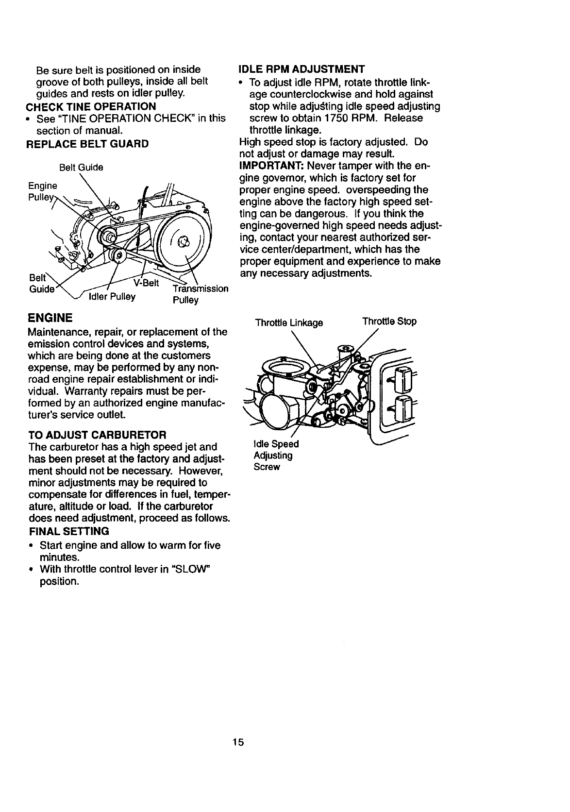
NOTE: If =ON" position check required
adjustment, recheck "OFP position
adjustment to insure tines do not rotate
when control is _OFP (up).
netr
Positiion line Control _, \
"ON" Position "'
Cable Cli "line Control Cable
/
\
TO REMOVE BELT GUARD
• Remove screws from side of belt guard.
•Pull belt guard out and away from unit.
• Replace belt guard by reversing above
procedure. Be sure slot in bottom of belt
guard is under head of tine shield bolt
and all nuts are tightened securely.
Sc__ _ Screw Guard
Screw
TO REPLACE V-BELT
Replace V-belt if it has stretched consider-
ably or if it has cracks or frayed edges.
Belt guard must be removed to service
belt. See "TO REMOVE BELT GUARD"
in this section of manual.
BELT REMOVAL
• Remove V-belt from transmission pulley
first and then from engine pulley.
BELT REPLACEMENT
•Install new V-belt to engine pulley first
then to transmission pulley•
14
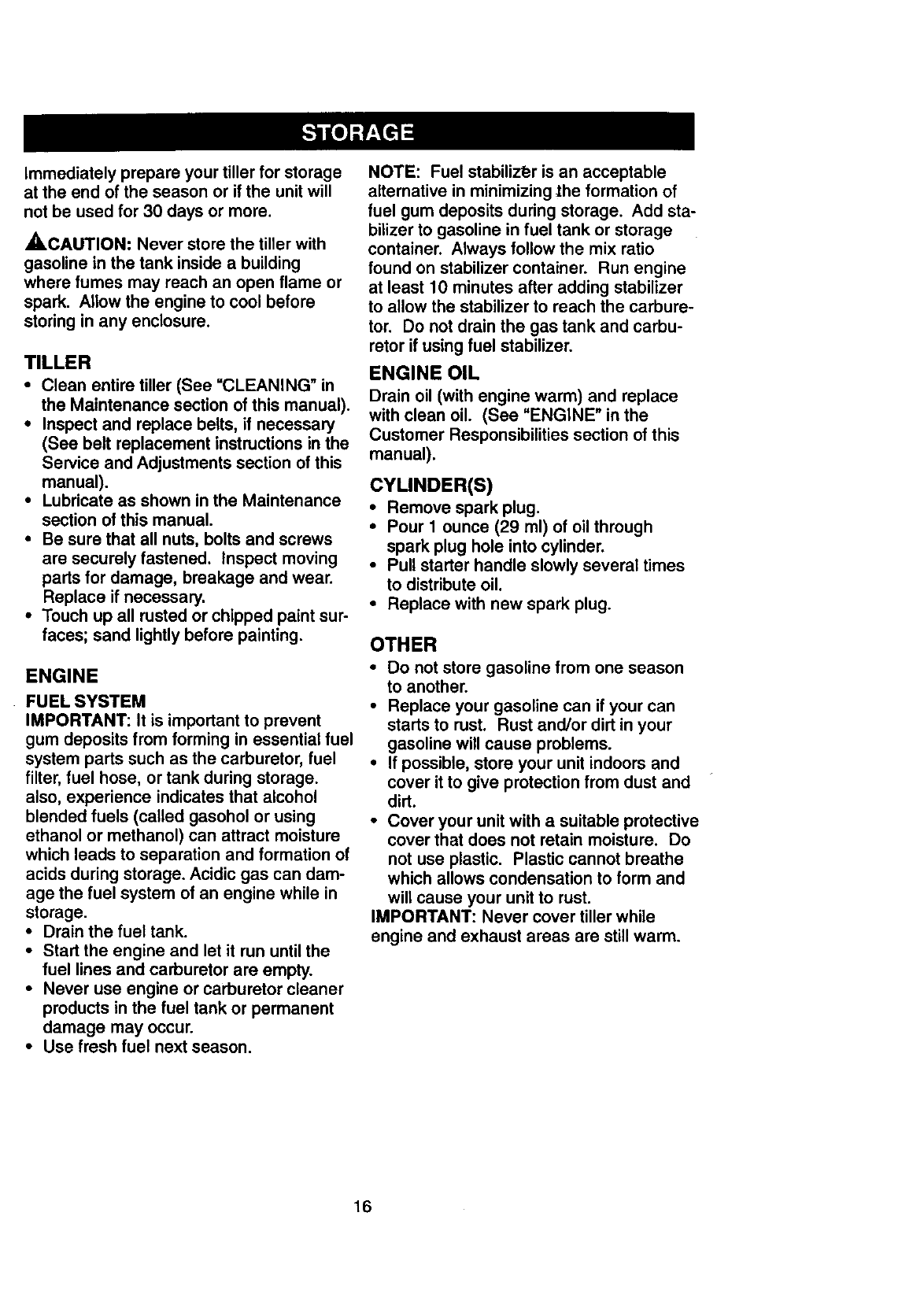
Be sure belt is positioned on inside
groove of both pulleys, inside all belt
guides and rests on idler pulley.
CHECK TINE OPERATION
•See "TINE OPERATION CHECK" in this
section of manual.
REPLACE BELT GUARD
Belt Guide
In, ine\ ,
gel \t'__
Guide_ .1-1-/'--'" Transmission
_J Idler Pulley Pulley
ENGINE
Maintenance, repair, or replacement of the
emission control devices and systems,
which are being done at the customers
expense, may be performed by any non-
road engine repair establishment or indi-
vidual. Warranty repairs must be per-
formed by an authorized engine manufac-
turer's service outlet.
TO ADJUST CARBURETOR
The carburetor has a high speed jet and
has been preset at the factory and adjust-
ment should not be necessary. However,
minor adjustments may be required to
compensate for differences in fuel, temper-
ature, altitude or load. If the carburetor
does need adjustment, proceed as follows.
FINAL SETI'ING
•Start engine and allow to warm for five
minutes.
•With throttle control lever in "SLOW"
position.
IDLE RPM ADJUSTMENT
•To adjust idle RPM, rotate throttle link-
age counterclockwise and hold against
stop while adjudting idle speed adjusting
screw to obtain 1750 RPM. Release
throttle linkage.
High speed stop is factory adjusted. Do
not adjust or damage may result.
IMPORTANT: Never tamper with the en-
gine governor, which is factory set for
proper engine speed, overspeeding the
engine above the factory high speed set-
ting can be dangerous. If you think the
engine-governed high speed needs adjust-
ing, contact your nearest authorized ser-
vice center/department, which has the
proper equipment and experience to make
any necessary adjustments.
Throttle Linkage
\Throttle Stop
Idle Speed
Adjusting
Screw
15
Immediately prepare your tiller for storage
at the end of the season or if the unit will
not be used for 30 days or more.
_,CAUTION: Never store the tiller with
gasoline in the tank inside a building
where fumes may reach an open flame or
spark. Allow the engine to cool before
storing in any enclosure.
TILLER
•Clean entire tiller (See =CLEANING" in
the Maintenance section of this manual).
•Inspect and replace belts, if necessary
(See belt replacement instructions in the
Service and Adjustments section of this
manual).
•Lubricate as shown in the Maintenance
section of this manual.
•Be sure that all nuts, bolts and screws
are securely fastened. Inspect moving
parts for damage, breakage and wear.
Replace if necessary.
•Touch up all rusted or chipped paint sur-
faces; sand lightly before painting.
ENGINE
FUEL SYSTEM
IMPORTANT: It is important to prevent
gum deposits from forming in essential fuel
system parts such as the carburetor, fuel
filter, fuel hose, or tank during storage.
also, experience indicates that alcohol
blended fuels (called gasohol or using
ethanol or methanol) can attract moisture
which leads to separation and formation of
acids during storage. Acidic gas can dam-
age the fuel system of an engine while in
storage.
•Drain the fuel tank.
•Start the engine and let it run until the
fuel lines and carburetor are empty.
•Never use engine or carburetor cleaner
products in the fuel tank or permanent
damage may occur.
•Use fresh fuel next season.
NOTE: Fuel stabilizt_r is an acceptable
alternative in minimizing the formation of
fuel gum deposits during storage. Add sta-
bilizer to gasoline in fuel tank or storage
container. Always follow the mix ratio
found on stabilizer container. Run engine
at least 10 minutes after adding stabilizer
to allow the stabilizer to reach the carbure-
tor. Do not drain the gas tank and carbu-
retor if using fuel stabilizer.
ENGINE OIL
Drain oil (with engine warm) and replace
with clean oil. (See "ENGINE" in the
Customer Responsibilities section of this
manual).
CYLINDER(S)
•Remove spark plug.
•Pour I ounce (29 ml) of oil through
spark plug hole into cylinder,
•Pull starter handle slowly several times
to distribute oil.
•Replace with new spark plug.
OTHER
• Do not store gasoline from one season
to another.
•Replace your gasoline can if your can
starts to rust. Rust and/or dirt in your
gasoline will cause problems.
•If possible, store your unit indoors and
cover it to give protection from dust and
dirt.
•Cover your unit with a suitable protective
cover that does not retain moisture. Do
not use plastic. Plastic cannot breathe
which allows condensation to form and
will cause your unit to rust.
IMPORTANT: Never cover tiller while
engine and exhaust areas are still warm.
16

PROBLEM
Will not start
Hard to start
Loss of power
CAUSE
1. Out of fuel.
2. Engine not "CHOKED"
properly.
3. Engine flooded.
4. Dirty air cleaner.
5. Water in fuel.
6. Clogged fuel tank.
7. Loose spark plug wire.
8. Bad spark plug or
improper gap.
9. Carburetor out of adjust-
ment.
1. Throttle control not set
properly.
2. Dirty air cleaner.
3. Bad spark plug or
improper gap.
4. Stale or dirty fuel.
5.
6.
Loose spark plug wire.
Carburetor out of.
adjustment.
1. Engine is overloaded.
2. Dirty air cleaner.
3. Low oil level/dirty oil.
4. Faulty spark plug.
5. Oil in fuel.
6. Stale or dirty fuel.
7. Water in fuel.
8. Clogged fuel tank.
9. Spark plug wire loose.
wire.
10. Dirty engine air screen.
11. Dirty/clogged muffler.
12. Carburetor out of
adjustment.
13. Poor compression.
17
1.
2.
3.
4.
5.
6.
7.
8.
9.
10.
11.
12.
13.
CORRECTION
1. Fill fuel tank.
2. See "TO START ENGINE" in.the
Operation section.
3. Wait several minutes before
attempting to start.
4. Clean or replace air cleaner car
tridge.
5. Drain fuel tank and carburetor,
and refill tank with fresh gasoline.
6. Remove fuel tank and clean.
7. Make sure spark plugwire is seat
ed properly on plug.
8. Replace spark plug or adjust gap.
9. Make necessary adjustments.
1. Place throttle control in "FAST"
position.
2. Clean or replace air cleaner car
tridge.
3. Replace spark plugor adjust gap.
4. Drain fuel tank and refillwith fresh
gasoline.
5. Make sure spark plug wire is seat
ed propedy on plug.
6. Make necessary adjustments.
Set depth stake and wheels for
shallower tilling.
Clean or replace air cleaner car
tridge.
Check oil level/change oil.
Clean and regap or change spark
plug.
Drain and clean fuel tank and
refill, and clean carburetor.
Drain fuel tank and refill with fresh
gasoline.
Drain fuel tank and carburetor,
and refill tank with fresh gasoline,
Remove fuel tank and clean.
Connect and tighten spark plug
Clean engine air screen.
Clean/replace muffler.
Make necessary adjustments.
Contact an authorized Sears
Service Center/Department.
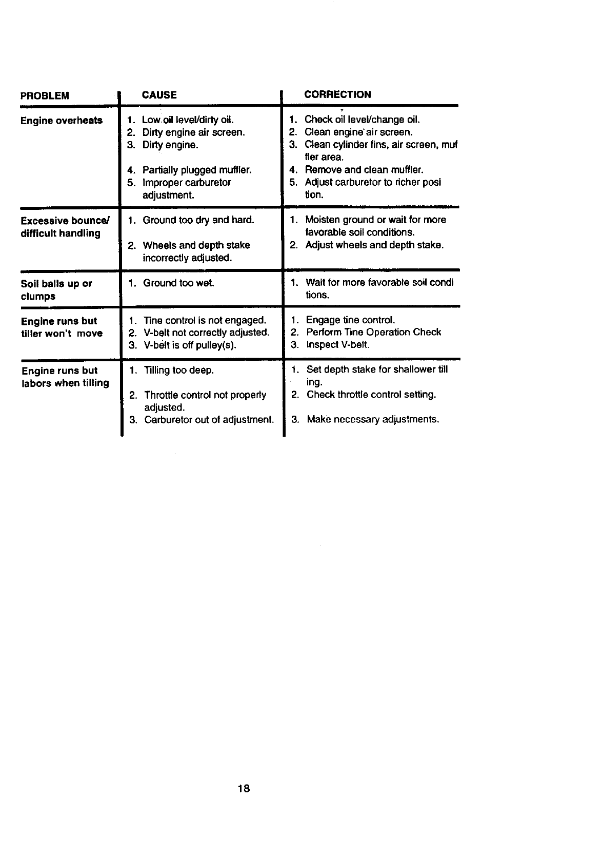
PROBLEM
Engine overheats
Excessive bounce/
difficult handling
Soil balls up or
clumps
Engine runs but
tiller won't move
Engine runs but
labors when tilling
CAUSE
!
1. Low oil level/dirtyoil
2. Dirty engine air screen.
3. Dirty engine.
4. Partially plugged muffler.
5. Improper carburetor
adjustment.
1. Ground too dry and hard.
.Wheels and depth stake
incorrectlyadjusted.
1. Ground too wet.
1. "13necontrol is not engaged.
2. V-belt not correctlyadjusted.
3. V-belt is off pulley(s).
1. "Rilingtoo deep.
2. Throttle control not properly
adjusted.
3. Carburetor out of adjustment.
CORRECTION
T
1. Check oil level/change oil.
2. Clean engine'air screen.
3. Clean cylinder fins, air screen, muf
tier area.
4. Remove and clean muffler.
5. Adjust carburetor to richer posi
tion.
1. Moisten ground or wait for more
favorable soil conditions.
2. Adjustwheels and depth stake.
1, Wait for more favorable soil condi
tions.
1. Engage tine control.
2. Perform'nne Operation Check
3. Inspect V-belt.
1. Set depth stake for shallower till
ing.
2. Check throttle control setting.
3. Make necessary adjustments.
18
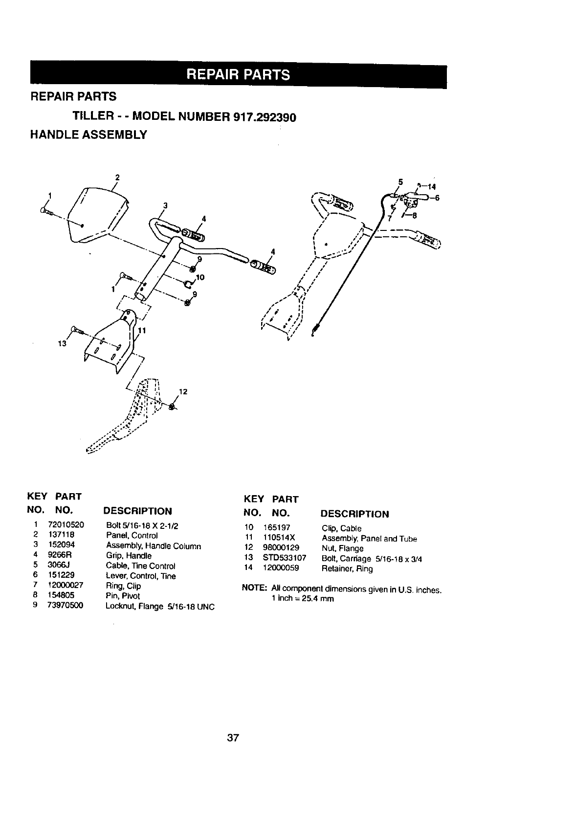
REPAIR PARTS
TILLER - -MODEL NUMBER 917.292390
HANDLE ASSEMBLY
3
1
4/
/
4_
/ /
/ /
/•
KEY PART
NO. NO.
1 72010520
2 137118
3 152094
4 9266R
53066J
6 151229
7 12000027
8 154805
973970500
DESCRIPTION
Bolt5/16-18 X 2-1/2
Panel, Control
Assembly,Handle Column
Grip, Handle
Cable, ]3ne Control
Lever, Control,"Sne
Ring,Clip
Pin, Pivot
Locknut, Flange 5/16-18 UNC
KEY PART
NO. NO. DESCRIPTION
10 165197 Clip, Cable
11 110514X Assembly, Panel and Tube
12 98000129 Nut, Flange
13 STD533107 Bolt, Carriage 5/16-18 x 3/4
14 12000059 Retainer,Ring
NOTE: All component dimensionsgiven inU.S. inches.
1 inch = 25.4 mm
37
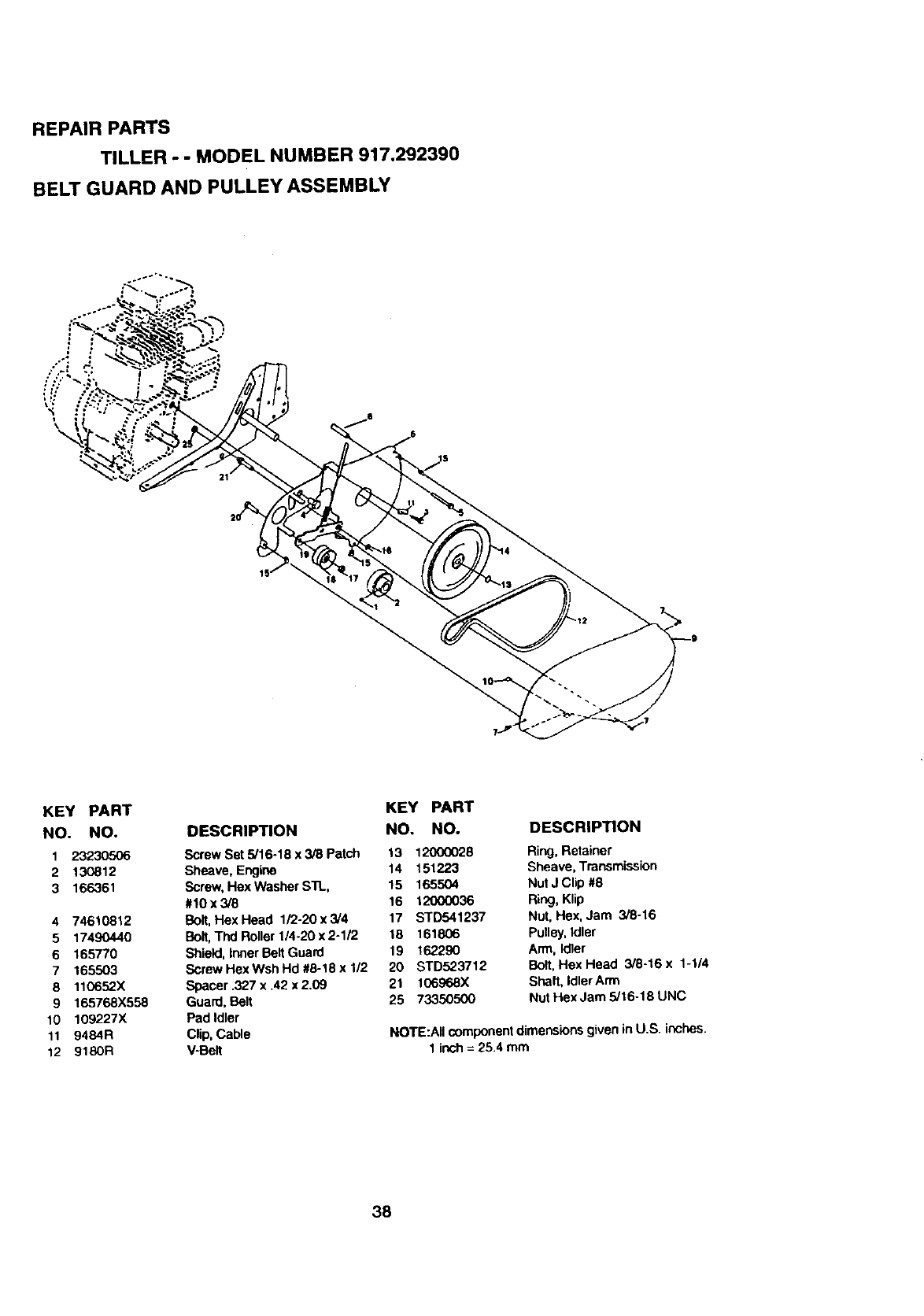
REPAIR PARTS
TILLER - - MODEL NUMBER 917.292390
BELT GUARD AND PULLEY ASSEMBLY
KEY PART
NO. NO.
1 23230506
2 130812
3 166361
4 74610812
5 17490440
6 165770
7 165503
8 110652X
9 165768x558
10 109227X
11 9484R
12 9180R
KEY PART
DESCRIPTION NO. NO.
Screw Set 5/16.18 x 3/8 Patch 13 120(X)028
Sheave, Engine 14 151223
Screw,Hex Washer sn_, 15 165504
#10 x 3/8 16 12000036
Bolt,HexHead 1/2-20x3/4 17 STD541237
Bolt,Thd Roller 1/4-20 x 2-1/2 18 161806
Shield,Inner BeltGuard 19 162290
Screw Hex Wsh Hd #8-18 x 1/2 20 STD523712
Spacer .327 x .42 x 2.09 21 106968X
Guard, Belt 25 73350500
Pad Idler
Clip, Cable
V-Belt
DESCRIPTION
Ring, Retainer
Sheave, Transmission
Nut J Clip #8
Ring, Klip
Nut, Hex, Jam 3/8-16
Pulley,Idler
Arm, Idler
Bolt,Hex Head 3/8-16 x 1-1/4
Shaft, Idler Arm
Nut Hex Jam 5/16-18 UNC
NOTE:All componentdimensionsgiven in U.S. inches.
1 inch= 25.4 mm
38
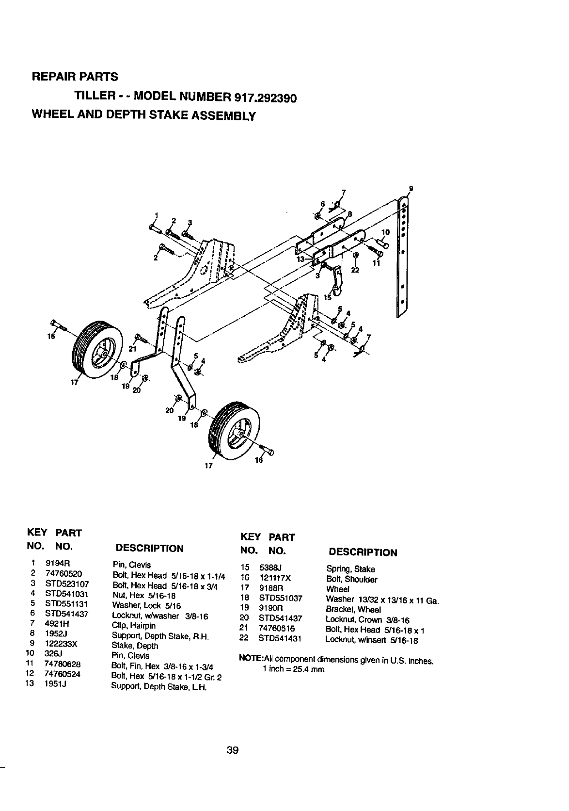
REPAIR PARTS
TILLER o- MODEL NUMBER 917.292390
WHEEL AND DEPTH STAKE ASSEMBLY
7
6
9
16
17 1_ 2o
1
•v16
17
KEY PART
NO. NO.
19194R
274760520
3 STD523107
4 STD541031
5 STD551131
6 STD541437
7 4921H
8 1952J
9 122233X
10 326J
11 74780628
12 74760524
13 1951J
KEY PART
DESCRIPTION NO. NO.
Pin, Clevis 15 5388J
Bolt,HexHead 5/16-18 x 1-1/4 16 121117X
Bolt,HexHead 5/16-18x3/4 17 9188R
Nut, Hex 5/16-18 18 STD551037
Washer,Lock 5/16 19 9190R
Lock.nut,w/_Nasher 3/8-16 20 STD541437
Clip, Hairpin 21 74760516
Support, Depth Stake, R.H. 22 STD541431
Stake, Depth
Pin, Clevis
Bolt, Fin, Hex 3/8-16 x 1-3/4
Bo_t,Hex 5/16-18 x 1-1/2 Gr. 2
Support, Depth Stake, L.H.
DESCRIPTION
Spdng,Stake
Bolt, Shoulder
Wheel
Washer 13/32 x 13/16 x 11Ga.
Bracket,Wheel
Lock,nut, Crown 3/8-16
Bolt,Hex Head 5/16-18 x 1
Lock.nut,w/insert 5/16-18
NOTE:Aftcomponentdimensionsgivenin U.S. inches.
1 inch= 25.4 mm
39
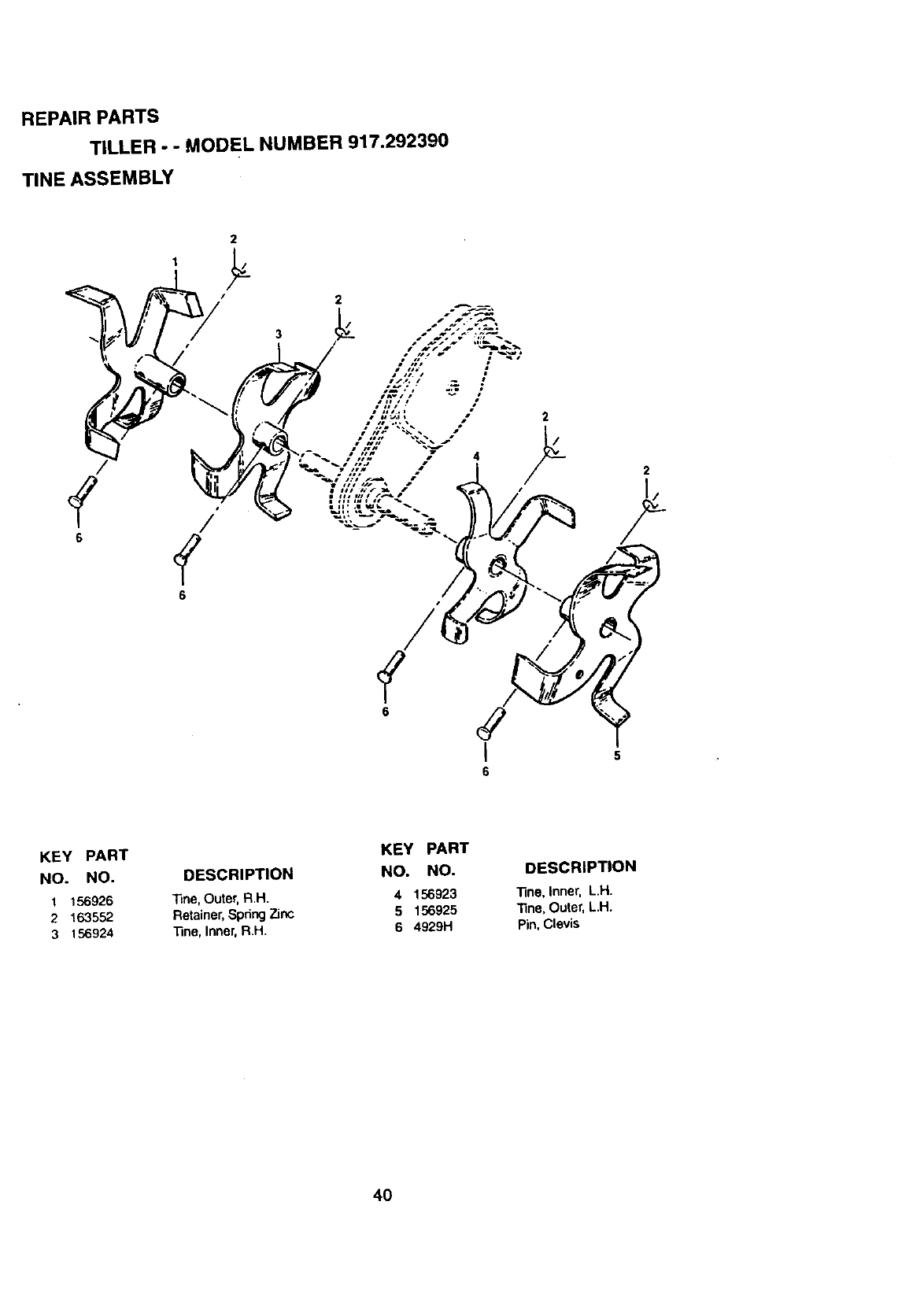
REPAIR PARTS
TILLER --MODEL NUMBER 917.292390
TINE ASSEMBLY
I
65
KEY PART
NO. NO.
1_56926
2 163552
3 156924
KEY PART
DESCRIPTION NO. NO.
Tine,Outer,R.H. 4 156923
Retainer,SpdngZinc 5 156925
_ne, Inner,RH. 6 4929H
DESCRIPTION
_ne, Inner, L.H.
]3he, Outer, L.H.
Pin, Clevis
4O
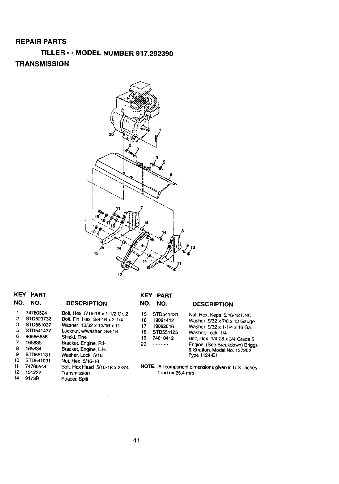
REPAIR PARTS
TILLER - - MODEL NUMBER 917.292390
TRANSMISSION
1
2o 23
11 7
14
14
12
8
10
11
KEY PART
NO. NO.
174760524
2 STD523732
3STD551037
5 STD541437
69056R558
7 165835
8 165834
9 STD55113t
10 STD541031
11 74760544
12 151222
14 9173R
DESCRIPTION
Bolt, Hex 5/16-18 x 1-1/2 Gn 2
Bolt, Fin, Hex 3/8-16 x 3-1/4
Washer 13/32 x 13/16 x 11
Locknut, w/washer 3/8-16
Shield, "13ne
Bracket, Engine, R.H.
Bracket, Engine, LH.
Washer, Lock 5/16
Nut, Hex 5/16-18
Bolt, Hex Head 5/16-18 x 2-3/4
Transmission
Spacer, Split
KEY PART
NO. NO.
15 STD541431
16 19091412
17 19092O16
18 STD551125
19 74610412
20 ......
DESCRIPTION
Nut, Hex, Keps 5/16-18 UNC
Washer 9/32 x 7/B x 12 Gauge
Washer 9/32 x 1-1/4 x 16 Ga,
Washer, Lock 1/4
Bolt, Hex 1/4-29 x 3/4 Grade 5
Engine, (See Breakdown) Briggs
&Stratton, Model No. 137202,
Type 1124-E1
NOTE: Allcomponentdimensionsgiven in U.S. inches.
1 inch = 25.4 mm
41
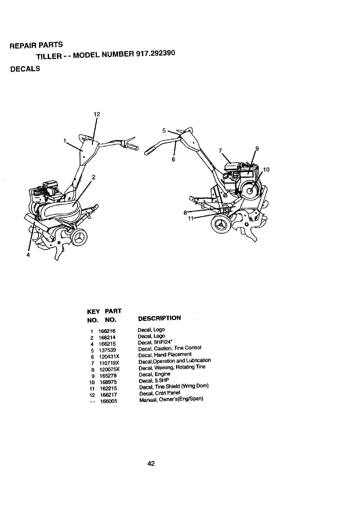
REPAIR PARTS
TILLER "" MODEL NUMBER 917.292390
DECALS
12
2
7
10
KEY PART
NO. NO. DESCRIPTION
1 166216 Decal, Logo
2 166214 Decal, Logo
4 166215 Decal, 5HP/24"
5 137539 Decal, Caution,'nne Control
6 120431X Decal, Hand Placement
7 110719X Decal,Operationand Lubrication
8 120075X Decal, Warning, Rotating'13ne
9 165279 Decal, Engine
10 168975 Decal, 5.5t"1P
11 162215 Decal, "13neShield (Wrog Dora)
12 166217 Decal, Cntd Panel
- - 166005 Manual, Owner's(Eno/SPan)
42
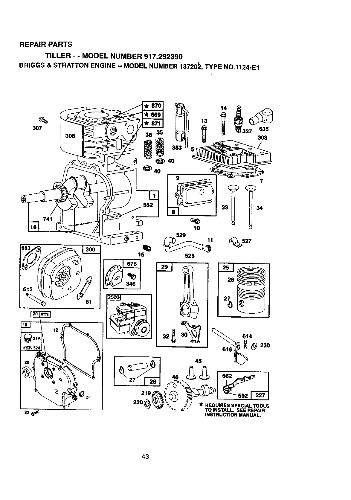
REPAIR PARTS
TILLER - - MODEL NUMBER 917.292390
BRIGGS & STRATTON ENGINE - MODEL NUMBER 13720_Z,TYPE NO.1124-E1
3O7
21
36 35
_4o
15
Z5001
9
10
14
7
33_ 34
_527
219
22O
46
45
"JkREQUIRES SPECIAL TOOLS
TO INSTALL SEE REPAIR
INSTRUCTION MANUAL.
43
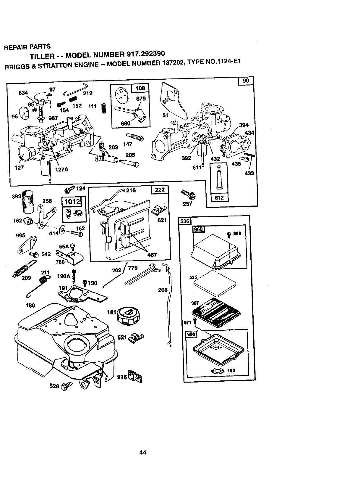
REPAIRPARTS
TILLER -- MODEL NUMBER 917,292390
BRIGGS & STRATTON ENGINE - MODEL NUMBER 137202, TYPE NO.1124-E1
621_
163
44
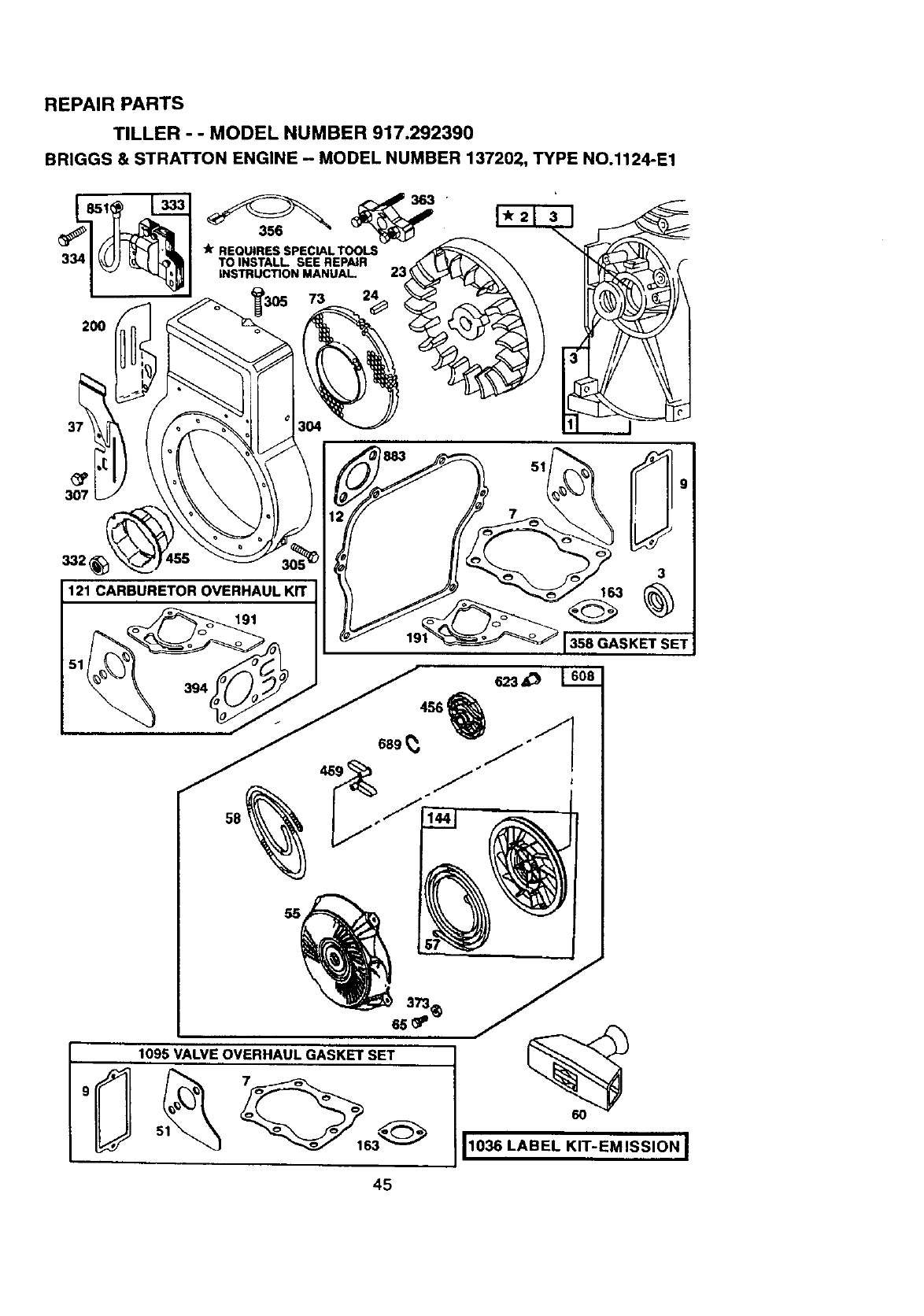
REPAIR PARTS
TILLER - - MODEL NUMBER 917.292390
BRIGGS & STRATTON ENGINE - MODEL NUMBER 137202, TYPE NO.1124-E1
2OO
307
191
3
163
358 GASKET SET
4SS_
689
373_
6s _'
1095 VALVE OVERHAUL GASKET SET
1036 LABEL KIT-EMISSION ]
45

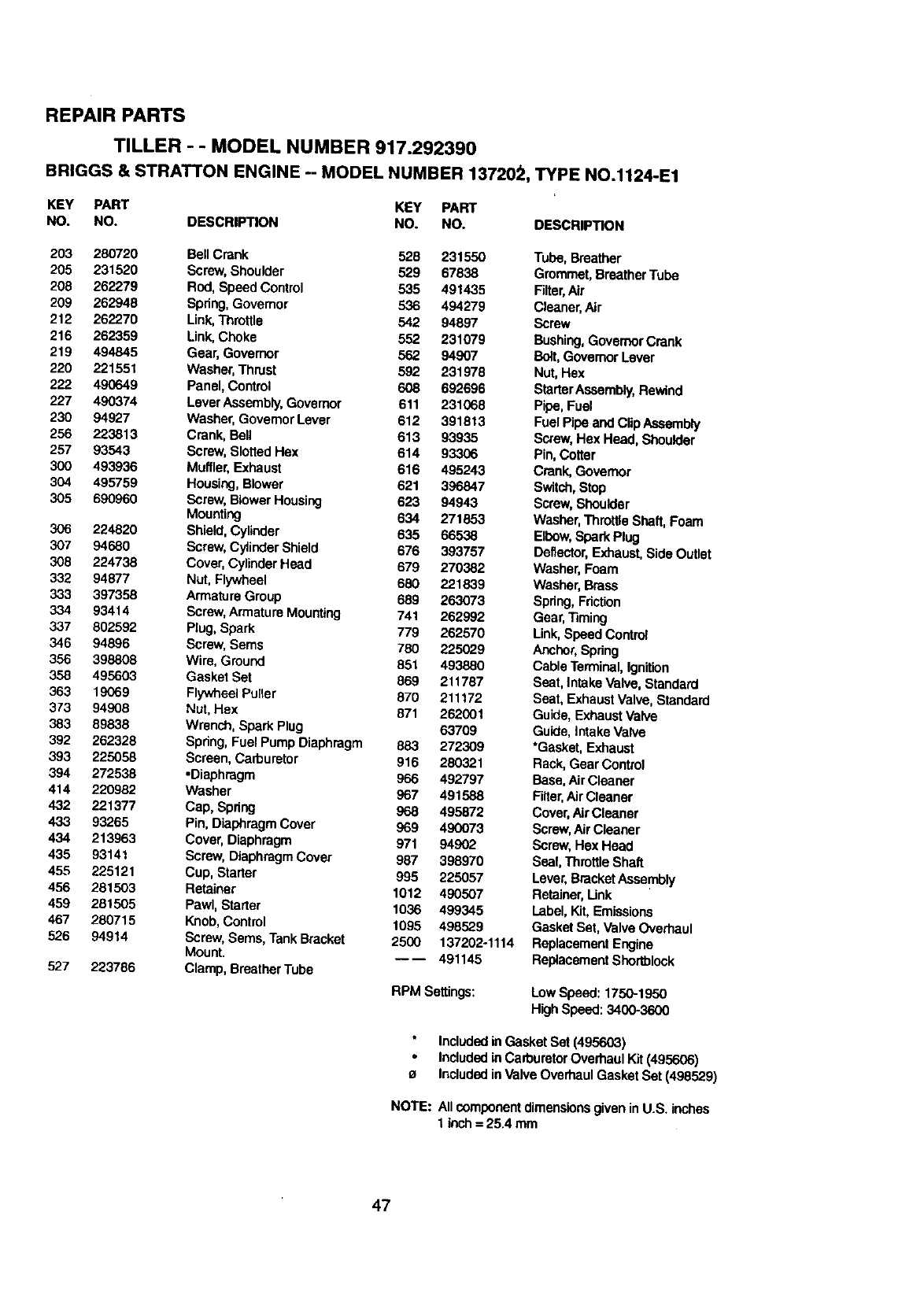
REPAIR PARTS
TILLER - - MODEL NUMBER 917.292390
BRIGGS & STRA'n'ON ENGINE - MODEL NUMBER 137202,TYPE NO.1124-E1
KEY PART KEY PART
NO. NO. DESCRIPTION NO. NO. DESCRIPTION
1497144 Cylinder Assembly 40 93312 Retainer,Intake Valve and
2399268 Bushing,Cylinder ExhaustSpring
3 299819 *Seal, Oil 45 260642 Tappet, Valve
5 214040 Head, Cylinder 46 214726 Gear, Cam
7 272157 e'Gasket, CylinderHead 51 273113 o,'Gasket, CarburetorMounting
8 495774 BreatherAssembly 55 497442 Housing,Rewind Starter
9 27549 g'Gasket, Valve Cover 56 498144 Pulley,Rewind Starter
10 94621 Screw, BreatherMounting 58 66894 Rope, Rewind Starter
11 66578 Grommet, BreatherTube (Cutto Required Length)
12 270080 "Gasket, Crankcase, Standard 60 393152 Handle, Rewind Starter
.015" 65 94904 Screw, Housing Mounting
270125 *Gasket, Crankcase .005"
Thick 65A 94669 Screw, Hex
270126 *Ca.'ket, Crankcase .009" 73 225176 Screen, Rotating
Thick 81 222263 Lock,Screw
13 94221 Screw, Cylinder Head 2-3/32" 90 498298 Carburetor Assembly
14 94679 Screw, CylinderHead 2-15/32" 95 93499 Screw, ThrottleValve to Shaft
15 94916 Plug, Pipe, Hex Socket 96 223793 Throttle,Carburetor
16 492088 Crankshaft 97 497600 Shaftand Lever,Throttle
94388 Gear Key,Crankshaft 108 497,230 Valve and Shaft Group,Choke
18 494044 Cover Assembly,Crankcase 111 262715 Spring,Choke
19 495660 Bushing,Crankcase Cover 118 231533 Valve, Needle
29 294606 *Seal, Oil 121 495606 CarburetorOverhaul Kit
21 281658 Plug, Oil Filler 124 94913 Screw, Hex Head
22 94980 Screw, Cover Mounting 127 220352 Plug, Welch
23 393673 Flywheel,Magneto 127A 223789 Plug, Welch
24 222698 Key,Flywheel 147 231955 Jet, Pilot
25 298904 PistonAssembly,StandardSize 152 260575 Spnng, ThrottleAdjustment
298905 Piston Assembly .010" 154 93527 Screw, Machine, Round Head
Oversize 162 490589 Screw and Cellar
298906 Piston Assembly .020" 163 271935 o'Gasket, AirCleaner Mounting
Oversize 180 495405 Tank Assembly, Fuel
298907 Piston Assembly .030" 181 494559 Cap, Fuel Tank
Oversize 190 94924 Screw, Fuel Tank
26 298982 Ring Set, Piston,Standard Size 190A 94919 Screw, Fuel Tank Mounting
299742 RingSet, Piston,Standard, 191 272489 -*Gasket, Fuel Tank to
Chrome Carburetor
298983 Ring Set, Piston .010" Oversize 200 223886 Guide, Air
298984 RingSet, Piston .020" Oversize 202 262280 Link, Mech. Governor
298985 Ring Set, Piston .030" Oversize
27 26026 Lock,PistonPin Included in Gasket Set (495603)
28 298909 PinAssembly,Piston, Standard IncludedinCarburetor Overhaul Kit (495606)
298908 PinAssembly,Piston .005" eIncludedin ValveOverhaul Gasket Set (498529)
Over
29 299430 RodAssembly,Connecting NOTE: Allcomponentdimensionsgiven inU.S. inches
390459 RodAssembly,Connecting 1 inch= 25.4 mm
.020" Undersize CrankpinBore
30 221890 Dipper,Connecting Rod
32 94745 Screw, ConnectingRod
33 211119 Valve, Exhaust
34 261044 Valve, Intake
35 260552 Spring, IntakeValve
36 26478 Spdng, ExhaustValve
37 2"2443 Guard, Flywheel
46
REPAIR PARTS
TILLER --MODEL NUMBER 917.292390
BRIGGS & STRATTON ENGINE -- MODEL NUMBER 13720;_, TYPE NO.1124-E1
KEY PART KEY PART
NO. NO. DESCRIPTION NO. NO. DESCRIPTION
203 280720 Bell Crank 528 231550 Tube, Breather
205 231520 Screw,Shoulder 529 67838 Grommet, Braather Tube
208 262279 Rod, Speed Control 535 491435 Filter,Air
209 262948 Spring, Govemor 536 494279 Cleaner,Air
212 262270 Link,Throttle 542 94897 Screw
216 262359 Link, Choke 552 231079 Bushing,GovernorCrank
219 494845 Gear, Governor 562 94907 Bait, GovernorLever
220 221551 Washer,Thrust 592 231976 Nut, Hex
222 490649 Panel, Control 608 692696 StarterAssembly,Rewind
227 490374 Lever Assembly,Governor 611 231068 Pipe, Fuel
230 94927 Washer, GovemorLever 612 391813 Fuel Pibe and ClipAssembly
256 223813 Crank, Ball 613 93935 Screw, Hax Head, Shoulder
257 93543 Screw, Slotted Hax 614 93306 Pin, Cotter
300 493936 Muffler,Exhaust 616 495243 Crank,Governor
304 495759 Housing,Blower 621 396847 Switch,Stop
305 690960 Screw, Blower Housing 623 94943 Screw, Shoulder
Mounting 634 271853 Washer,Throt_e Shaft, Foam
306 224820 Shield, Cylinder 635 66538 Elbow, Spark Plug
307 94680 Screw, CylinderShield 676 393757 Deflector,Exhaust,Side Outlet
308 224738 Cover,Cylinder Head 679 270382 Washer, Foam
332 94877 Nut, Flywheel 680 221839 Washer, Brass
333 397358 Armature Group 689 263073 Spdng, Friction
334 93414 Screw,Armature Mounting 741 262992 Gear, Timing
337 802592 Plug, Spark 779 262570 Link,Speed Control
346 94896 Screw, Sems 780 225029 Anchor,Spring
356 398808 Wire, Ground 851 493880 Cable Terminal,Ignition
358 495603 Gasket Set 869 211787 Seat, Intake Valve, Standard
363 19069 Flywheel Puller 870 211172 Seat, ExhaustValve, Standard
373 94908 Nut, Hex 871 262001 Guide, ExhaustValve
383 89838 Wrench, Spark Plug 63709 Guide, IntakeValve
392 262328 Spr_ng,Fuel Pump Diaphragm 883 272309 *Gasket, Exhaust
393 225058 Screen, Carburetor 916 280321 Rack, Gear Control
394 272538 -Diaphragm 966 492797 Base,AirCleaner
414 220982 Washer 967 491588 Fitter,Air C_aanar
432 221377 Cap, Spring 968 495872 Cover,Air Cleaner
433 93265 Pin, Diaphragm Cover 969 490073 Screw,Air Cleaner
434 213963 Cover, Diaphragm 971 94902 Screw, Hex Head
435 93141 Screw, Diaphragm Cover 987 398970 Seal, Throttle Shaft
455 225121 Cup, Starter 995 225057 Lever,BracketAssembly
456 281503 Retainer 1012 490507 Retainer,link
459 281505 Pawi, Starter 1036 499345 Label, Kit,Emissions
467 280715 Knob, Control 1095 498529 Gasket Sat, Valve Overhaul
526 94914 Screw, Seres, Tank Bracket 2500 137202-1114 Replacement Engine
Mount. ---- 491145 ReplacementShortblock
527 223786 Clamp, BreatherTube
RPM Settings: LowSpeed:1750-1950
HighSpeed:3400-3600
Includedin Gasket Set (495603)
Includedta CaCouretorOverhaul Kit (495606)
a Includedin Valve Overhaul Gasket Set (498529)
NOTE: Allcomponentdimensionsgiven in U.S. inches
1 inch= 25.4 mm
47
For in-home major brand repair service:
Call 24 hours a day, 7 days a week
1-800-4-MY-HOME _M(1-800-469-4663)
Para pedir servicio de reparacibn adomicilio
1-800-676-5811
In Canada for all your service and parts needs call
Au Canada pour tout le service ou les pieces
1-800-665-4455
For the repair or replacement parts you need:
Call 6 am-11pm CST, 7 days a week
PartsDirect sM
1-800-366-PART (1-800-366-7278)
Para ordenar piezas con entrega a domicilio
1-800-659-7084
For the location of a Sears Parts and Repair Center
in your area:
Call 24 Hours a day, 7 days a week
1-800-488-1222
For information on purchasing a Sears Maintenance
Agreement or to inquire about an existing Agreement:
Call 9 am-5 pm, Monday - Saturday
1-800-827-6655
HorneCentralsM
166005 Rev. 2 1.14.99 TR Printed in U.S.A.
