CRAFTSMAN Edger Manual L0106149
User Manual: CRAFTSMAN CRAFTSMAN Edger Manual CRAFTSMAN Edger Owner's Manual, CRAFTSMAN Edger installation guides
Open the PDF directly: View PDF ![]() .
.
Page Count: 40
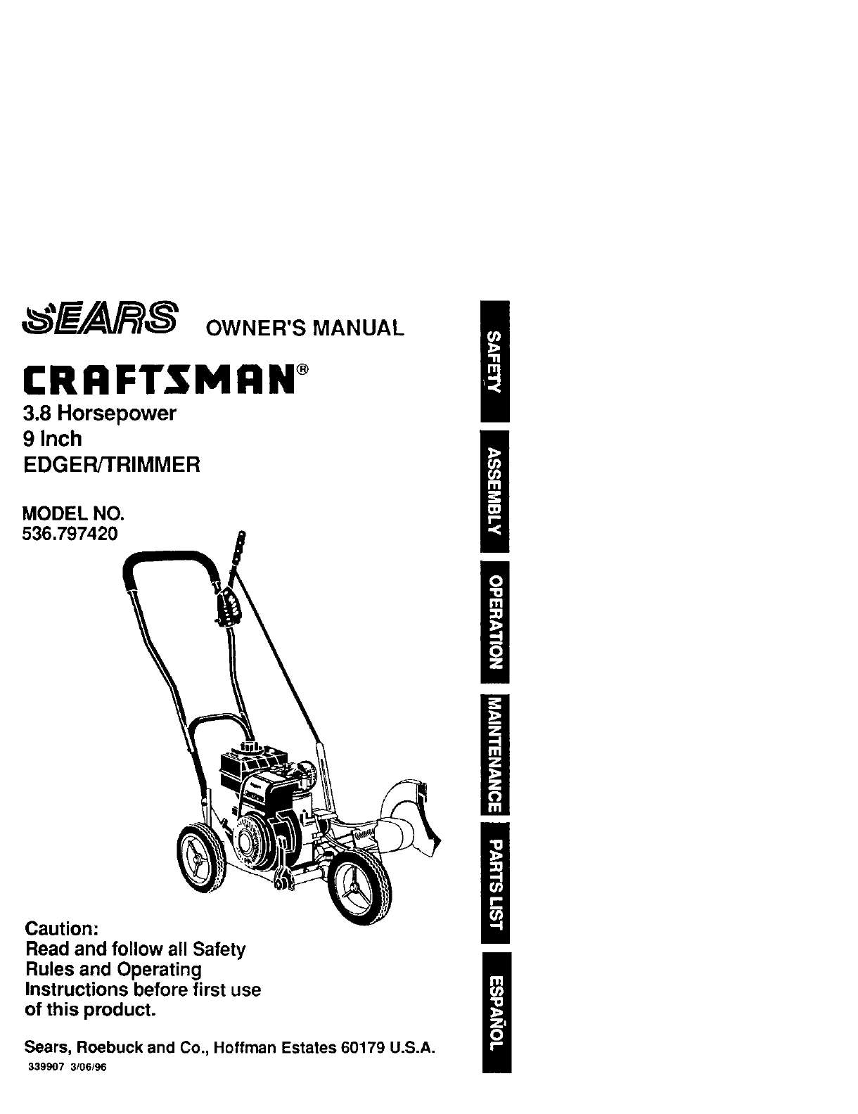
CRRFTSMRN ®
3.8 Horsepower
9 Inch
EDGER/TRIMMER
MODEL NO.
536.797420
Caution:
Read and follow all Safety
Rules and Operating
Instructions before first use
of this product.
Sears, Roebuck and Co., Hoffman Estates 60179 U.S.A.
339907 3/06/96
I
D
n
H
m
D
Table of Contents 2 Service and Adfustments 13-14
Warranty 2 Storage 14-15
Safety Rules 2-3 TroubJeshootmg 15
Contents of Sh_ppmg Carton 4 Spanish (Espa5ol) 16-30
Assembly 5-7 Edger Repair Parts 31-35
Operatnon 7-11 Engnne Repair Parts 36-39
Maintenance 11-12 Parts Ordenng/Serwce Back Cover
LIMITED ONE-YEAR WARRANTY ON CRAFTSMAN EDGER/TRIMMER
For one year from the date of purchase, when this Craftsman Edger/Trimmer Is main-
tained, lubncated, and tuned up according to the operating and maintenance tnstruc-
tnons m the owner's manual, Sears wdl repanr, free of charge, any defect _n material or
workmanship
If thrs Craftsman EdgerFFnmmer is used for commercial or rental purposes, this war-
ranty apphes for only 90 days from the date of purchase
This warranty does not cover the following
•Expendable items wh)ch become worn durJng normal use, such as spark plugs, etc
• Repairs necessary because of operator abuse or neghgence, including bent crank
shafts and the failure to maintain the equppment according to the instruchons con-
tained =nthe owner's manual
WARRANTY SERVICE IS AVAILABLE BY RETURNING THE CRAFTSMAN EDGER/
TRIMMER TO THE NEAREST SEARS SERVICE CENTER/DEPARTMENT IN THE
UNITED STATES THIS WARRANTY APPLIES ONLY WHILE THIS PRODUCT IS IN
USE IN THE UNITED STATES
Thrs warranty gwes you specffnc legal rights and you may also have other rnghts whnch
may vary from state to state
Sears, Roebuck and Co, D817WA, Hoffman Estates, IL 60179
/_ Look for this symbol to point out important safety precautions. It means---
AI-rENTION!!! Become alert_!J Your safety is Involved.
,Z_ CAUTION: Always disconnect spark
plug wire and place wire where _1cannot
contact spark plug to prevent accidental
starting when setting-up, transporting.
adlastlng or making reparrs
IMPORTANT: Safety standards require
operator presence controls to mJnlmnze the
nsk of mlary Your Edger/Tnmmer _s
equipped with such controls Do not attempt
to defeat the function o1 the operalor
presence control under any cnrcumstances
BEFORE USE
• Read the owner's manual carefurly Be
thoroughly familiar with the controls and
the proper use of the edger/trimmer
Know how to stop the edger/trimmer and
disengage the controls quickly
• Do not operate the edger'tnmmer wuthout
wearing adequate outer garments Wear
footwear that wdl improve footing on
stnppery surfaces
• Keep the area o1 operation clear of all
persons, particularly small children and
pets
•ThorougHy inspect the area where the
edger/trimmer asto be used and remove
all foreign oblects
FUEL SAFETY
• Handle fuel wnth care, ttns hnghly flam-
mable
• Use an approved container
• Check fuel supply before each use,
allowing space for expansion as the heat
of the engine and_or sun can cause fuel 1o
expand
• Fill fuel tank outdoors wnth extreme care
Never fill fuel tank indoors Replace fuel
tankcap securely and wtpe up spilled
fuel
•Never remove the fuel tank cap or add
fuel to a runmng or hot engme
•Never store fuel or edger/Lnmmer wtth
fuel in the tank inside a building where
fumes may reach an open flame
OPERATING SAFETY
• Never allow children or young teenagers
to operate the edger/_rtmmar Keep them
away whtle _tis operating Never allow
adults to operate the edger/tnmmer
wrthout proper instruction
• Do not operate this machine d you are
taking drugs or other medlcat_on which
can cause drowsiness or affect your
ablhty to operate thrs machine
• Do not use this machine if you are
mentally or physically unable to operate
this machtna safely
• Always wear safety glasses or eye
shields dunng operation or while perform-
rng an adjustment or repair to protect
your eyes from foreign obleCts that may
be thrown from the edger/tnmmer
•Do not put hands or feet near or under
rotating parts
• Exercise extreme ceut_on when operating
on or crossing gravel drives, walks, or
roads Stay alert for h_dden hazards or
traffic
•Exercise caution to avoid slipping or
falhng
• Never operate the edger_rrmmer without
proper guards, plates, or other safety
protective devices m place
• Never operate the edgerttnmmer at htgh
transport speeds on shppery surfaces
Look behind and use care when backing
• Never allow bystanders near the edger/
trlnlmer
• Keep ohddren and pets away wh_le
operating
•Never operate the edgerrt nmmer without
good wslbd_ty or hght
• Do not run the engine indoors The
exhaust fumes are dangerous, contalmng
CARBON MONOXIDE, an ODORLESS
and DEADLY GAS
•Take all possible precautions when
leaving the edger/trimmer unattended
Stop the engine
• Do not overload the edger/trammer
capacity by attempting to edge too deep
at too fast a rate
SAFE STORAGE
•Always refer to the owner's manual
instructions for important deta,{s ,{ the
edgert[nmmer is to be stored for an
extended period
• Never store the edger/trimmer wJth fuel _n
the fuel tank inside a budding where
ignition sources are present such as
water and space heaters, clothes dryers.
and the hke Allow the engpne to cool
before stonng in any enotosure
• Keep the edger/trimmer tn safe working
condihon Check all fasteners at frequent
intervals for proper tightness
REPAIR/ADJUSTMENTS SAFETY
•After striking a foreign object, stop the
engine (motor) Remove the wJre from the
spark plug, and keep the wrre away from
the plug to prevent acctdenta! startmg
Thoroughly inspect the edger_tnmmer for
any damage, and repair the damage
before restarting and operating _t
•If edger/Lnmmer should start to vtbrate
abnormally, stop engine (motor) and
check tmmedlately for the cause
Vibrabon ts generally awarmng of
trouble
• Stop the blade whenever you leave the
operating pes=tton Also. dtsconnect the
spark plug wire before unclogging the
blades and when makrng any repairs,
adlustments, or mspecttons
•When cleamng, repamng, or _nspechng.
shut off the engine and make certain all
mowng parts have stopped
• Neverattempttomakeanyadjustments
while the engine is runmng except when
spec,ficaliy recommended by the manu-
facturer
Z_ WARNING: The engine exhaust
from this product contains chemicals
known to the State of California to cause
cancer, b=rth defects or other reproductive
harm
Z_ WARNING: This umt Rsequipped
with an internal combustion engine and
should not be used on or near any unim-
proved forest-covered, brush-covered or
grass-covered land unless the engme's ex-
haust system is equipped wdh a spark at-
rester meeting apphceble local or state laws
(_fany) If a spark arrester is used tt should
be maintained in effective workJng order by
the operator
In the state of Cahforma the spark arrester
_s required by law (Sect,on 4442 of the Cah-
fornla Pubhc Resources Code) Other
states may have slmriar laws Federal laws
3
apply on federal lands A spark arrester/
muffler _savailable through your nearest Sears Authonzed Service Center (See RE-
PAIR PARTS section mthis manual)
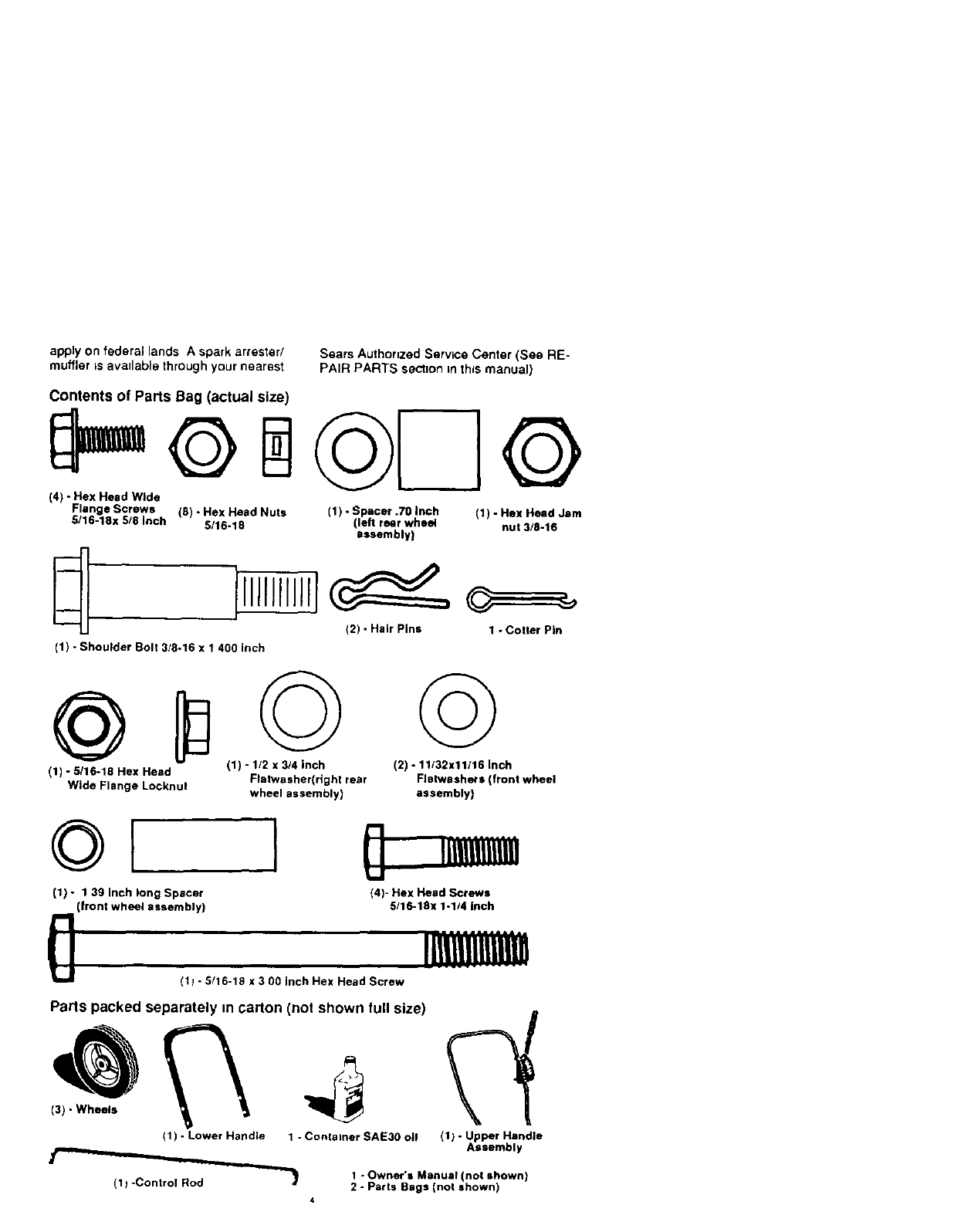
Contents of Parts Bag (actual size)
(4) - Hex Head Wide
Flange Screws
5/16-16x 5/8 Inch (8) - Hex Head Nuts (1) - Spacer .70 Inch (1) -Hex Head Jam
5/16-18 (len rear whe(d nut 3/8-16
assembly)
(2) - Hair Pins 1 -Cotter Pin
(1) - Shoulder Bolt 3/8-16 x 1 400 Inch
(1) -6116-16 Hex Head
Wide Flange Locknul
©
(1) - 1/2 x314 inch
Flatwasher(right rear
wheel assembly)
©
(2) - 11132x11/16 Inch
Flatwash_s (front wheel
assembly)
(1) - 1 39 Inch long Spacer
(front wheel assembly)
I[] iulJlllijl,J
I.i
(4)- Hex Head Screws
6/16-16x 1o1/4Inch
0(11 -5/16-18 x 3 00 inch Hex Head Screw
Parts packed separately m carton (not shown full size)
(1) -Lower Handle 1 -Container SAE30 oil (1) -Upper Handle
Assembly
1 - Owner's Manual (not shown)
(1 _-Control Rod _1_ 2 - Parts Bags (not shown)
4
.'_'$:t=1_I']_'
LL_ CAUTION: Always wear safety
glasses or eye shields while assembling
Edger/Tnmmer
TOOLS REQUIRED FOR ASSEMBLY
2-1/2 inch Wrenches
(or adjustable wrench)
2 - 9/16 inch Wrenches
(or adjustable wrenches)
2 - Adjustable Wrenches
1 - Regular Screwdriver
1 - Phers
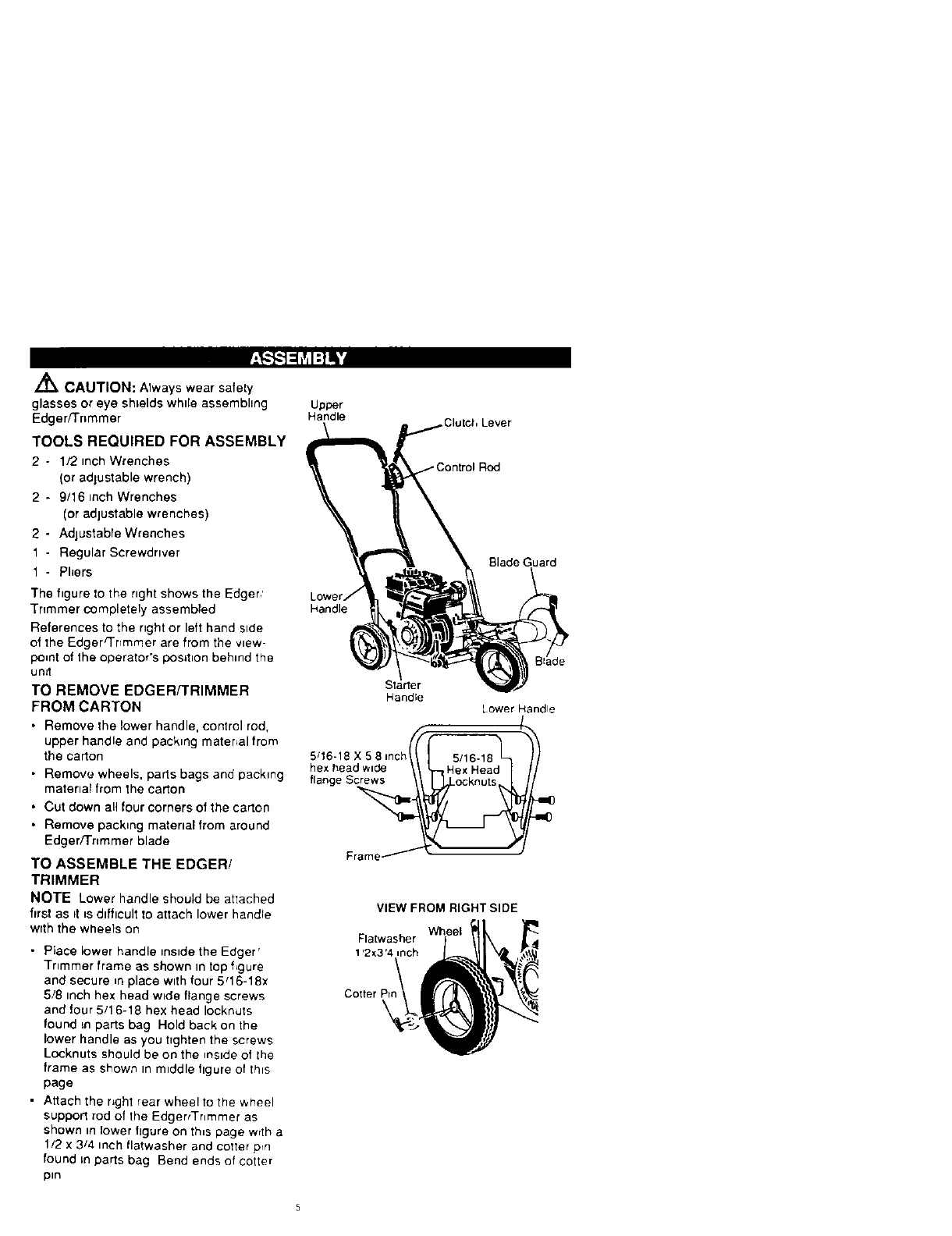
The figure to the nght shows the Edger,'
Tnmmer completely assembled
References to the nght or left hand side
of the Edger_nmmer are from the view-
po=nt of the operator's position behind the
unit
TO REMOVE EDGERf'FRIMMER
FROM CARTON
• Remove the lower handle, control rod,
upper handle and packing matenal from
the carton
• Remove wheels, parts bags and packing
materlat from the carton
• Cut down all four corners of the carton
• Remove packing material from around
Edger/Trtmmer blade
TO ASSEMBLE THE EDGER/
TRIMMER
NOTE Lower handle should be attached
first as it _sdifficult to attach lower handle
with the wheels on
•Place lower handle inside the Edger'
Trimmer frame as shown in top f_gure
and secure _n place with four 5q6-18x
5/8 inch hex head wide flange screws
and four 5/1 6-18 hex head IockmJtS
found _n parts bag Hold back on the
lower handle as you tighten the screws
Locknuts should be on the reside of lhe
frame as shown m middle figure of this
page
• Attach the right rear whee! to the wheel
support rod of the EdgertTr_mmer as
shown in lower figure on this page wrth a
1/2 x 3/4 inch Ilatwasher and cotter prn
found =n parts bag Bend ends of cotter
pin
Upper
Handle ,Clutch Lever
Slade Guard
Handle
Starter
Handle Lower Handle
/.
5q6-18 X 5 8 inch _5/16.18
hexheadw_de ,H_xH_ad I
flange Screws
Frame _ ,
=0
m0
VIEW FROM RIGHT SIDE
Wheel
Flatwasher
1'2_3'4 inch
Cotter P=
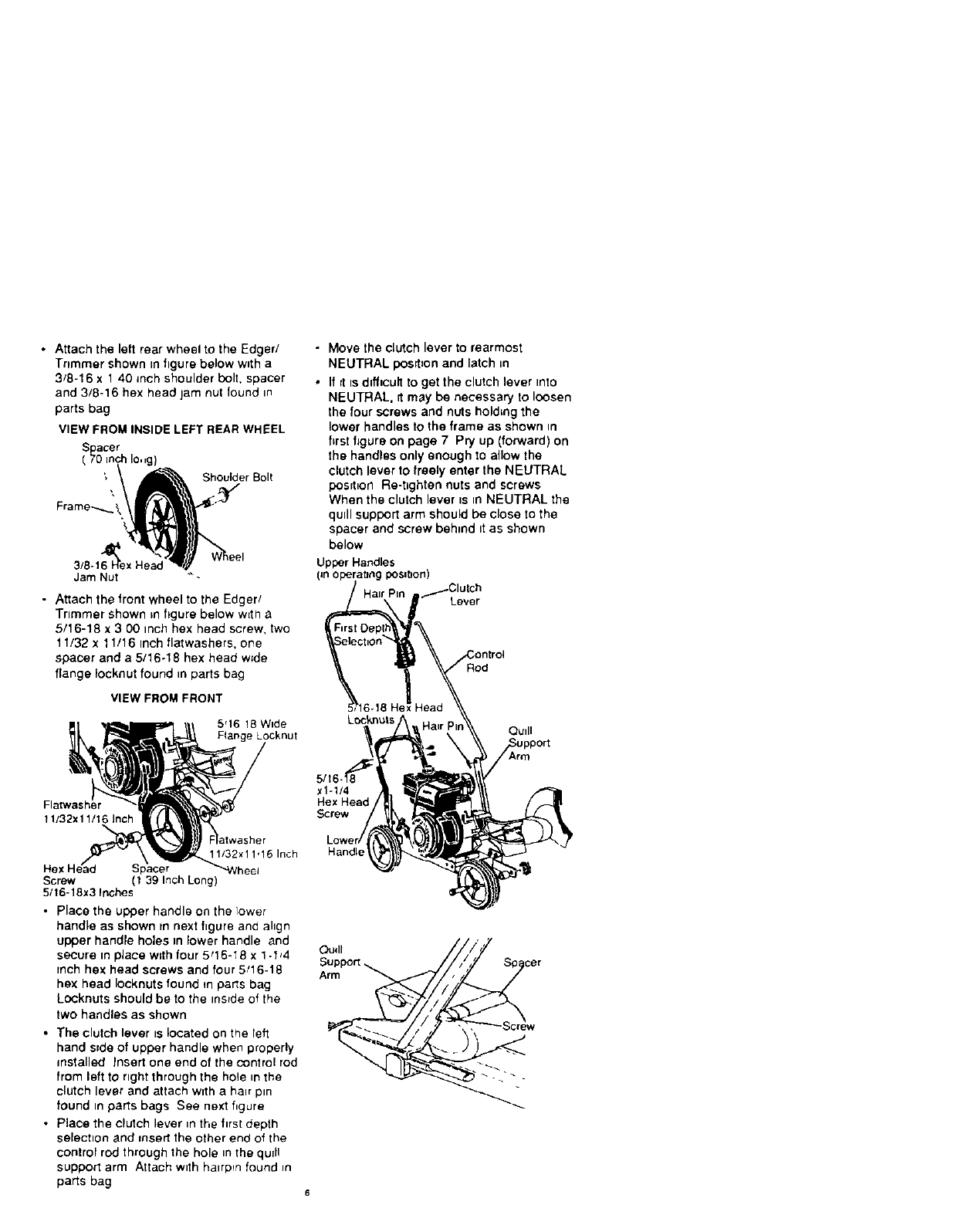
• Attach the left rear wheel to the Edger/
Trimmer shown in figure below w_th a
3/8-16 x 1 40 inch shoulder bolt, spacer
and 3/8-16 hex head jam nut found in
parts bag
VIEW FROM INSIDE LEFT REAR WHEEL
S_acer
(10 inch Io,,g)
Shoulder Bolt
3/8-16
Jam Nut _-
• Attach the front wheel to the Edger/
Trimmer shown in figure below wElha
5/16-18 x 3 00 inch hex head screw, two
11/32 x 11/16 inch flatwashers, one
spacer and a 5/16-18 hex head wide
flange Focknut found in parts bag
VIEW FROM FRONT
5q6 !8 Wide
Flange Locknut
11/32x 11!16 Inch
11/32x11,16 Inch
eel
Screw (1 39 Inch Long)
5/16-18x3 Inches
• Place the upper handle on the lower
handle as shown in next hgure and ahgn
upper handle holes mlower handle and
secure in place with four 5q6-18 x 1 -I_4
rnch hex head screws and four 5/16-18
hex head Iocknuts found mparts bag
Locknuts should be to the reside of the
two handles as shown
• The clutch lever is located on the left
hand side of upper handle when properly
installed Insert one end of the control rod
from left to right through the hole m the
clutch lever and attach wrth a hair pin
found in parts bags See next figure
•Place the clutch lever m the first depth
selection and insert the other end of the
control rod through the hole in the qu[ll
support arm Attach with halrppn found _n
parts bag
•Move the clutch lever to rearmost
NEUTRAL posrt_on and latch =n
• If =tis dtfficult to get the clutch lever rote
NEUTRAL. rt may be necessary to loosen
the four screws and nuts holding the
lower handles to the frame as shown in
hrst figure on page 7 Pry up (forward) on
the handles only enough 1oallow the
clutch lever to freely enter the NEUTRAL
posd_on Re-t=ghten nuts and screws
When the clutch lever is tn NEUTRAL the
qudl support arm should be close to the
spacer and screw behind tt as shown
below
Upper Handles
Lever
Rod
Lockn_ts Qudl
x1-1/4
Hex Head
Screw
Handle
Oudl
Arm
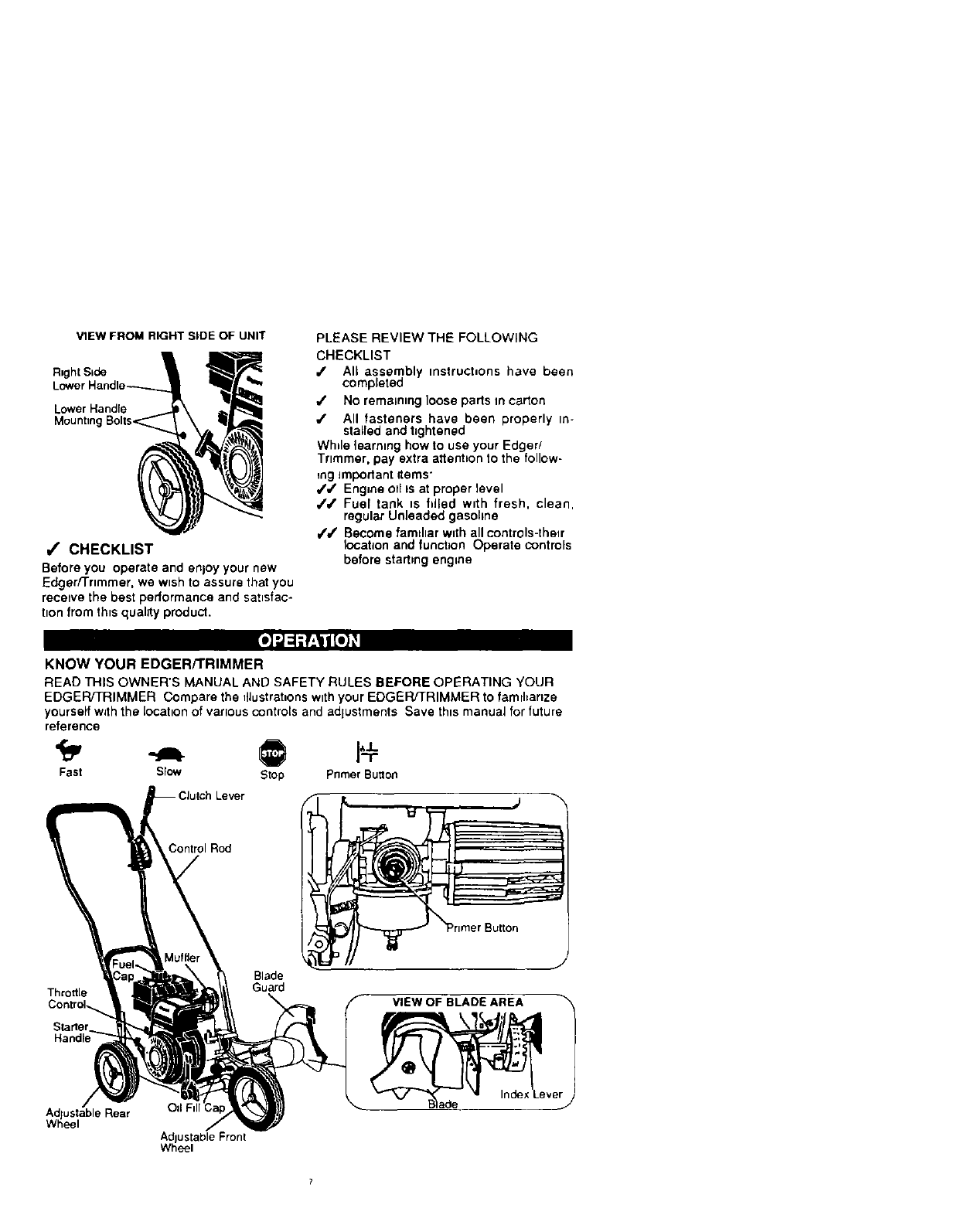
VIEW FROM RIGHT SIDE OF UNIT
Flught S=de
Lower Handre
JCHECKLIST
Before you operate and enjoy your new
Edger/Trimmer, we wtsh to assure that you
recmve the best performance and satisfac-
tion from th=squality producL
PLEASE REVIEW THE FOLLOWING
CHECKLIST
_' All assembly instructions have been
completed
4' No remaining loose parts vncarton
•1" All fasteners have been properly in-
stalled and t=ghtened
Wh=lelearnmg how to use your Edger/
Trimmer, pay extra attent=on to the follow-
mg important items"
4'#' Engine otl ts at proper level
/,/' Fuel tank =s filled wdh fresh, clean,
regular Unleaded gasohne
,f#' Become famdiar wnthall controls-thmr
location and function Operate controls
before startingengine
KNOW YOUR EDGER/TRIMMER
READ THIS OWNER'S MANUAL AND SAFETY RULES BEFORE OPERATING YOUR
EDGER/TRIMMER Compare the fllustrat=onsw=thyour EDGER/TRIMMER to famlhanze
yourselfw_ththe location of various controls and adjustments Save this manual for future
reference
Fast Slow Stop PrimerButton
Control Rod
Throttle
Control._
Starter
Blade
Guard
VIEW OF BLADE AREA
Ad ustable Rear OII F
Whee
AdJustable Front
Wheel
Throttle Control - Used to control the en-
gine speed.
Primer Button - Injectsfuel directlyinto the
carburetor manifold for faster starts.
Starter Handle - The engineon this Edger/
Trimmer is equipped with an easy pui)recoil
starter.
Clutch Lever - Used to start and stopthe
blade and controlthe depth of cut.
Blade Guard - Used to prevent stones or
other material from being thrown at the op-
erator.
Index Lever - Permits adjustment from the
edging (vertical) positionto trimming (hod-
zontal) position.To change position,pullthe
index lever and rotate the quillassembly to
the desired angle or position.
Adjustable Rear Wheel -Right rear wheel
is adjustable to level Edger/Trimmer when
edging along acurb(curb-hopping).
Adjustable Front Wheel - Front wheel is
adjustable from side-to-side for balance.
Also, can be adjusted down for curb-hop-
ping.
HOW TO USE YOUR EDGER
/_ WARNING: The operation of this
Edger/Trimmer can resutt inforeign objects
being thrown intothe eyes, which can cause
severe eye damage. Always wear safety
glasses or eye shields while operating the
Edger/Trimmer.
We recommend standard safety glasses or
Wide Vision Safety Mask for over your
glasses.
TO STOP EDGER/TRIMMER
• To stop the engine, make sure the clutch
lever is all the way back or up and move
the throttle control lever to the STOP
siton.
Z_ CAUTION: Never leave the Edger/
Trimmer unattended white the engine is
running. Always disengage the cutting blade
and stop the engine.
TO USE THROTI'LE CONTROL
• Run at fullengine speed during normal
use.
•Push throttle control lever up to fncrease
speed; down to decrease speed.
TO USE PRIMER BUTTON
•Push primer button five times. See page 7
figure for location. Wait about two
8
seconds between each push.
• Do not useprimer buttonto restart a
warm engine after a short shutdown.
TO USE THE CLUTCH LEVER
• Start the engine and move the clutch
lever forward or down to engage the
cutting blade.
•Select the edging depth you need.
There are 5 selectionsup to 2-3/4
inchesdeep.
IMPORTANT: If vary deep edging is
required, we recommend that a shal-
low cut be made first, then cuts at
greater depths until the desired depth
is obtained.
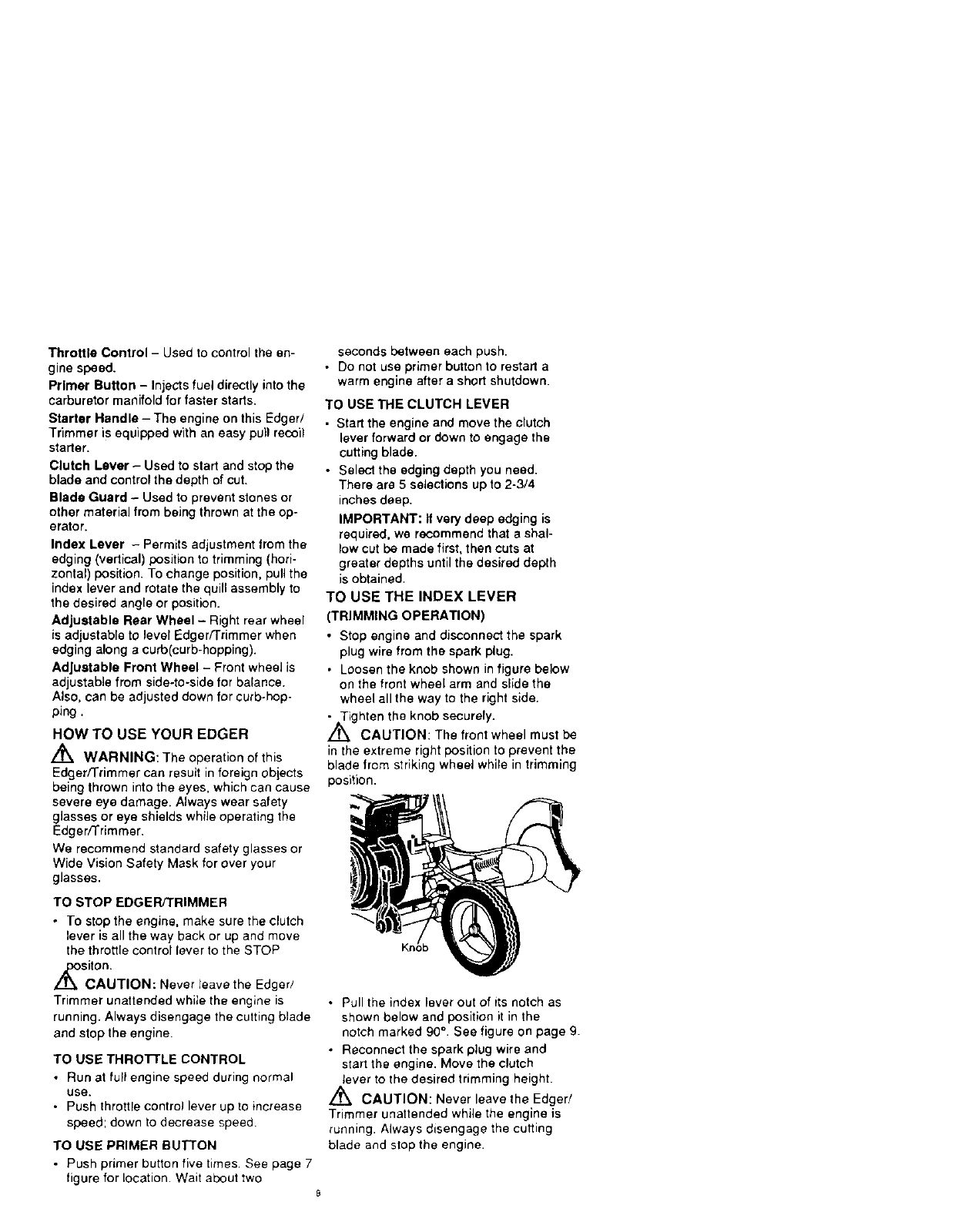
TO USE THE INDEX LEVER
(TRIMMING OPERATION)
•Stop engine and disconnect the spark
plug wire from the spark plug.
• Loosen the knob shown in figure below
on the front wheel arm and slide the
wheel all the way to the right side.
• Tighten the knob securely.
/_ CAUTION: The front wheel must be
in the extreme right position to prevent the
blade from striking wheel while in trimming
position.
• Pull the index lever out of its notch as
shown below and position it in the
notch marked 90 °. See figure on page 9.
• Reconnect the spark plug wire and
start the engine. Move the clutch
tever to the desired trimming height.
,_ CAUTION: Never leave the Edger/
Trimmer unattended while the engine is
running. Always disengage the cutting
blade and stop the engine.
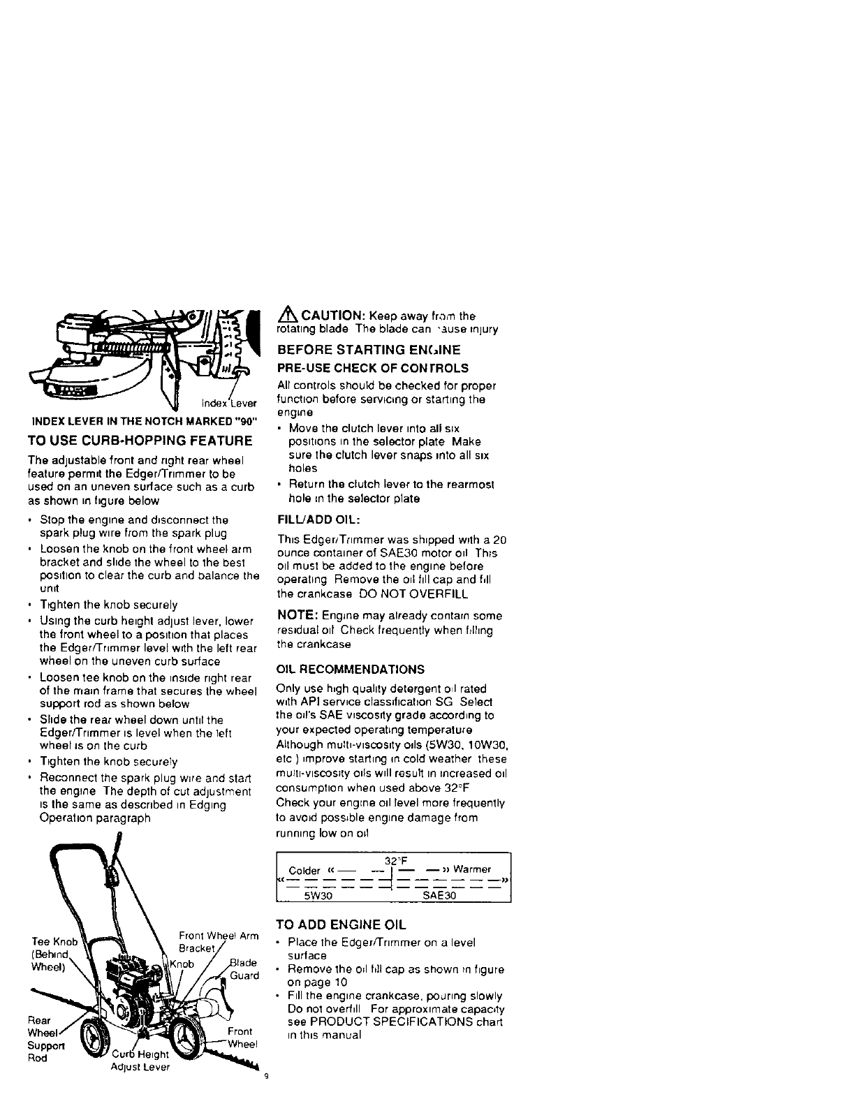
INDEX LEVER IN THE NOTCH MARKED "90"
TO USE CURB-HOPPING FEATURE
The adjustable front and right rear wheel
feature permit the Edger/Trimmer to be
used on an uneven surface such as a curb
as shown in figure below
• Stop the engine and disconnect the
spark plug wtre from the spark plug
• Loosen the knob on the front wheel arm
bracket and shde the wheel to the best
posttlon to clear the curb and balance the
unit
•Ttghten the knob securely
• Using the curb height adjust lever, lower
the front wheel to a posttton that places
the Edger/Tnmmer level with the left rear
wheel on the uneven curb surface
• Loosen tee knob on the reside right rear
of the rnam frame that secures the wheel
support rod as shown below
• Shde the rear wheel down unttlthe
Edger/'i'rtmmer ts level when the left
wheeIJs on the curb
• T_ghten the knob securely
• Reconnect the spark plug w=re and start
the engine The depth of cut adjustment
ts the same as descrtbed m Edging
Operation paragraph
Tee Kno Front Wheet Arm
(Behind
Wheel) _Guard
Rear
Support
Rod Adjust Lever
Front
/_ CAUTION: Keep away fra,'n the
rotating blade The blade can "Ruse injury
BEFORE STARTING EN(JINE
PRE-USE CHECK OF CON rROLS
Air controls should be checked for proper
function before servicing or starting the
engine
• Move the clutch lever mto all s_x
postt_ons tn the selector plate Make
sure the clutch lever snaps rote all six
holes
• Return the clutch lever to the rearmost
hole =nthe selector plate
FILtJADD OIL:
This Edger/Trimmer was shipped with a 20
ounce container of SAE30 motor oil Th_s
Oll must be added to the engine before
operating Remove the o_1ftll cap and fill
the crankcase DO NOTOVERFILL
NOTE: EngJne may already contarn some
residual eli Check frequently when filhng
the crankcase
OIL RECOMMENDATIONS
Only use h_gh quahty detergent o_lrated
w_th API service classification SG Select
the o_rs SAE wecoslty grade according to
your expected operating temperature
Although mulh-wscoslty OdS (5W30, 10W30,
etc ) _mprove starting m cold weather these
mu_h-VlSCOS_IyOtis wdl result In increased od
consumptton when used above 32°F
Check your engEne Oll level more frequently
to avoid possible engine damage from
running low on o=1
Colder (€ __)> _Warmer___))
(
5W30
TO ADD ENGINE OIL
• Place the Edger/]rtmmer on a level
surface
•Remove the o;I ft]l cap as shown tn hgure
on page 10
• Ftll the engine crankcase, poJrmg slowly
Do not overfill For approximate capaoty
see PRODUCT SPECIFICATIONS chart
in th_s manual
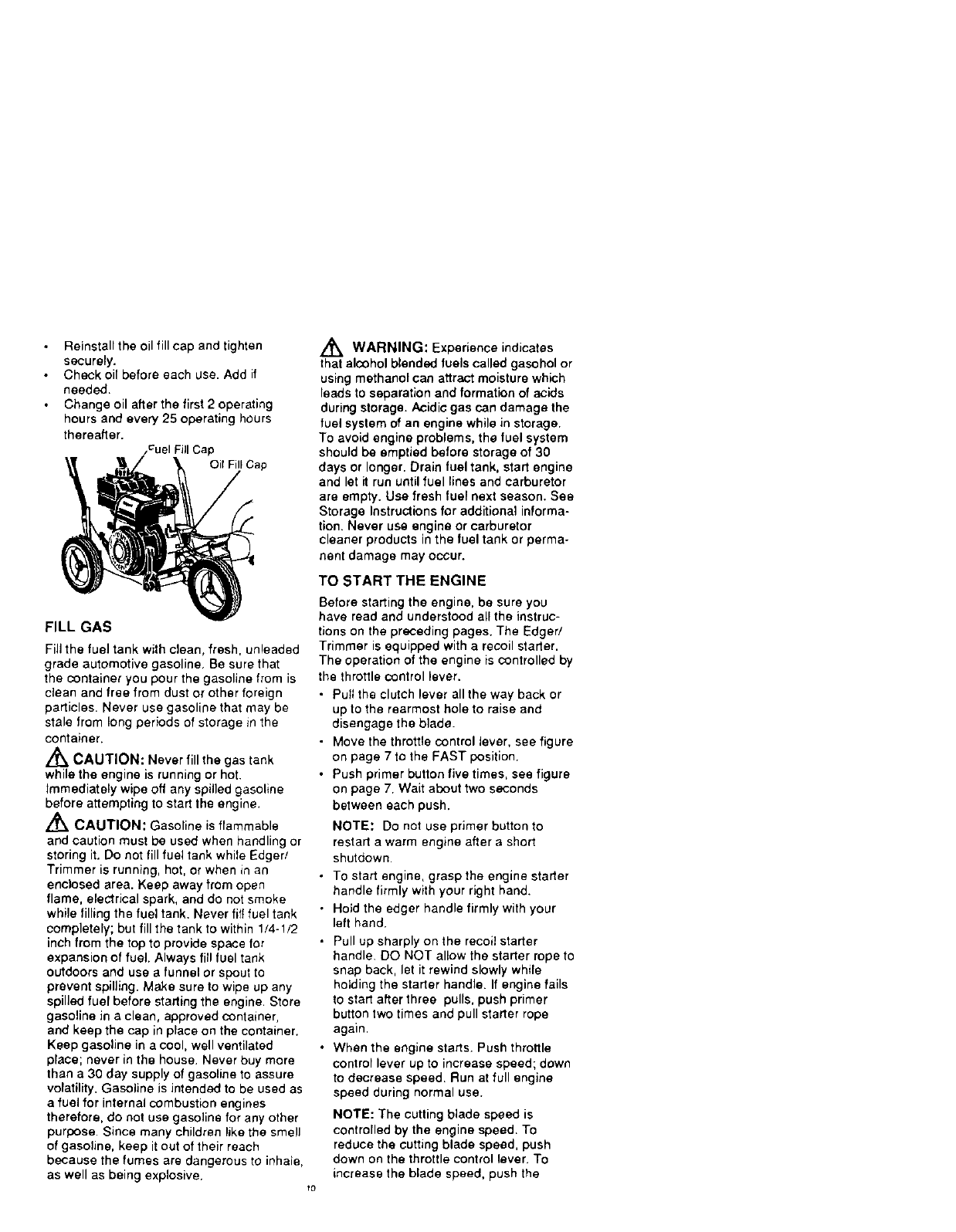
Reinstalltheoilfillcapandtighten
securely.
Checkoilbeforeeachuse.Addif
needed.
Changeoilafterthefirst2operating
hoursandevery25operatinghours
thereafter.
_CuelFillCap
Oil Fill Cap
FILL GAS
Fill the fuel tank with clean, fresh, unleaded
grade automotive gasoline, Be sure that
the container you pour the gasoline from is
clean and free from dust or other foreign
particles. Never use gasoline that may be
stale from long periods of storage in the
container.
/_ CAUTION: Never fill the gas tank
while the engine is running or hot.
Immediately wipe off any spilled gasoline
before attempting to start the engine.
,_ CAUTION: Gasoline is flammable
and caution must be used when handling or
storing it. Do not fill fuel tank while Edger/
Trimmer is running, hot, or when in an
enc)osed area. Keep away from open
flame, electrical spark, and do not smoke
while filling the fuel tank. Never lilt fuel tank
completely; but fill the tank to within 1/4-!/2
inch from the top to provide space for
expansion of fuel. Always fill fuel tank
outdoors and use afunnel or spout to
prevent spilling. Make sure to wipe up any
spilled fuel before starting the engine. Store
gasoline in a clean, approved container,
and keep the cap in place on the container.
Keep gasoline in a cool, well ventilated
place; never in the house. Never buy more
than a 30 day supply of gasoline to assure
volatility. Gasoline is intended to be used as
a fuel for internal combustion engines
therefore, do not use gasoline for any other
purpose. Since many children like the smell
of gasoline, keep it out of their reach
because the fumes are dangerous to inhale,
as well as being explosive.
,_ WARNING: Experience indicates
that alcohol blended fuels called gasohol or
using methanol can attract moisture which
leads to separation and formation of acids
during storage. Acidic gas can damage the
fuel system of an engine while in storage.
To avoid engine problems, the fuel system
should be emptied before storage of 30
days or longer. Drain fuel tank, start engine
and let it run until fuel lines and carburetor
are empty. Usa fresh fuel next season. See
Storage Instructions for additional informa-
tion. Never use engine or carburetor
cleaner products in the fuel tank or perma-
nent damage may occur.
TO START THE ENGINE
Before starting the engine, be sure you
have read and understood all the instruc-
tions on the preceding pages. The Edged
Trimmer is equipped with a recoil starter.
The operation of the engine is controlled by
the throttle control lever.
•Pull the clutch lever all the way back or
up to the rearmost hole to raise and
disengage the blade.
• Move the throttle control lever, see figure
on page 7 to the FAST position.
• Push primer button five times, see figure
on page 7. Wait about two seconds
between each push.
NOTE: Do not use primer button to
restart awarm engine after a short
shutdown.
• To start engine, grasp the engine starter
handle firmly with your right hand.
• Hold the edger handle firmly with your
left hand.
• Pull up sharply on the recoil starter
handle. DO NOT allow the starter rope to
snap back, let it rewind slowly while
holding the starter handle. If engine fails
to start after three pulls, push primer
button two times and pull starter rope
again.
•When the engine starts. Push throttle
control lever up to increase speed; down
to decrease speed. Run at full engine
speed during normal use.
NOTE: The cutting blade speed is
controlled by the engine speed. To
reduce the cutting blade speed, push
down on the throttle control lever. To
increase the blade speed, push the
_rottlecontrolleverup
• Tostoptheengine,makesuretheclutch
leverisallthewaybackorupandmove
thethrottlecontrollevertotheSTOP
position.
/_ CAUTION: Never run the engine
indoors or in a poorly ventilated area.
Engine exhaust contains carbon monoxide,
an odorless and deadly gas. Keep hands,
feet, hair and loose clothing away from any
moving parts on the engine or edger/
trimmer. Avoid the muffler and surrounding
areas. Temperatures may exceed 150 °F.
EDGING TIPS
• Edging is best performed when conditions
are dry. If the soil is to wet, dirt becomes
packed in and around the blade causing
premature belt wear and decreased
performance.
• If dirt does become packed around the
blade, stop the engine, remove the spark
plug wire, and remove the packed debris
before continuing to edge.
• If very deep edging is required, we
recommend that a shaltow cut be made
first, then cuts at greater depth until the
desired depth is obtained.
• Uniform edging can be performed when
the blade guide rides on and against the
surface which you are edging.
• Edging can be customized by varying the
number of passes and by the distance
your blade is from the surface you are
edging.
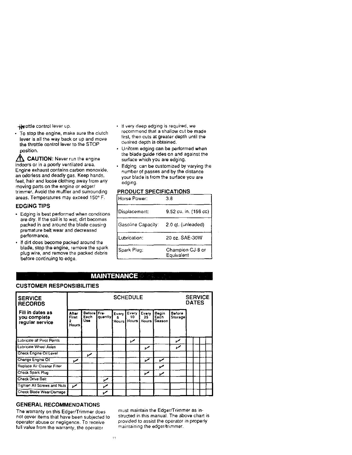
PRODUCT SPECIFICATIONS
Horse Power: 3.8
Displacement: 9.52 cu. in. (156 c¢)
Gasoline Capacity: 2.0 qt, (unleaded)
Lubrication: 20 oz, SAE-30W
Spark Plug: Champion CJ-8 or
Equivalent
CUSTOMER RESPONSIBILITIES
SERVICE
RECORDS
Fill in dates as
you complete
regular service
Lubricate all Pivot Points
Lubricate Wh_l Axles
Check Engine Oil Level
Change Engine Oil
Replace Air Cleaner Filter
Check Spark Plug
Check Drive Belt
Tighten All Screws and Nu[s
Check Blade Wear/Damage
After
First
2
Hours
Be|ore =re-
Each luenny
Use
V"
SCHEDULE SERVICE
DATES
Every _Every I
Every 10 | 2_ I
5
Hours Hours IHours I
v"
•;t
• ;!'
I
Begin Before
Eacft Storage
Season
v"
GENERAL RECOMMENDATIONS
The warranty on this Edger/Trimmer does
not cover items that have been subjected to
operator abuse or negligence. To receive
full value from the warranty, the operater
must maintain the Edger/Trimmer as in-
structed in this manual. The above chart is
provided to assist the operator in properly
maintaining the edger/trimmer.
11
LUBRICATION
• After each 25 hours of use of your edger/
trimmer, apply lightmachine oil to all
moving parts, particularly the wheels.
• The oil in the engine crankcase must be
changed after the first 2 hours of opera-
tion and after each 25 hours of use there-
after. See OIL RECOMMENDATIONS in
OPERATIONAL sectional in this manual
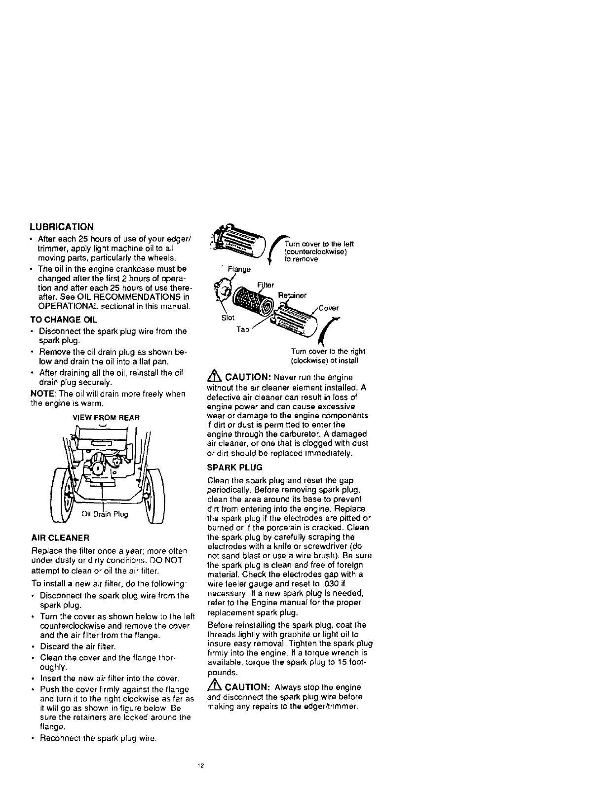
TO CHANGE OIL
•Disconnect the spark plugwire fromthe
spark plug.
•Remove the oil drain plug as shown be-
low and drain the oil into a flat pan.
•After draining all the oil, reinstall the oil
drain plug securely.
NOTE; The oil will drain mare freely when
the engine is warm.
VIEW FROM REAR
il Drain Plug
AIR CLEANER
Replace the filter once a year; more often
under dusty or dirty conditions. DO NOT
attempt to clean or oil the air filter.
To instaif a new air filter, do the following:
•Disconnect the spark plug wire from the
spark plug.
•Turn the cover as shown below to the left
counterclockwise and remove the cover
and the air filter from the flange.
• Discard the air filter.
•Clean the cover and the flange thor+
oughly,
•Insert the new air filter into the cover.
•Push the cover firmly against the flange
and turn it to the right clockwise as far as
it will go as shown in figure below. Be
sure the retainers are locked around the
flange,
•Reconnect the spark plug wire.
•Flange
Slot
Tab
Turn cover to the right
(clockwise) ot install
Z_ CAUTION: Never run the engine
without the air cleaner element installed. A
defective air cleaner can result in loss of
engine power and can cause excessive
wear or damage to the engine components
if dirt or dust is permitted to enter the
engine through the carburetor. A damaged
air cleaner, or one that is clogged with dust
or dirt should be replaced immediately.
SPARK PLUG
Clean the spark plug and reset the gap
periodically. Before removing spark plug,
clean the area around its base to prevent
dirt from entering into the engine, Replace
the spark plug if the electrodes are pitted or
burned or if the porcelain is cracked. Clean
the spark plug by carefully scraping the
electrodes with a knife or screwdriver (do
not sand blast or use a wire brush). Be sure
the spark plug is clean and free of foreign
material. Check the electrodes gap with a
wire feeler gauge and reset to .030 if
necessary. If a new spark plug is needed,
refer to the Engine manual for the proper
replacement spark plug.
Before reinstalling the spark plug, coat the
threads lightly with graphite or light oil to
insure easy removal. Tighten the spark plug
firmly into the engine. If atorque wrench is
available, torque the spark plug to 15 foot-
pounds.
/'_ CAUTION: Always stop the engine
and disconnect the spark plug wire before
making any repairs to the edgerttrimmer.
12
-]
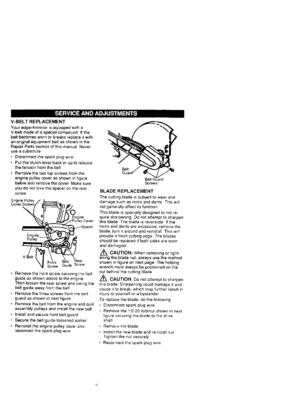
V-BELT REPLACEMENT
Your edgerrtnmmer _sequtpped w_th a
V-belt made of a special compound If the
belt becomes worn or breaks replace tt wtth
an ortgnal equtpment belt as shown m the
Reparr Parts sectton of th_s manual Never
use a subshtute
•Dtsconnect the spark plug w,re
• Put the clutch lever back or up to release
the tension from the belt
• Remove the two top screws from the
engtne pulley cover as shown In figure
below and remove the cover Make sure
you do not lose the spacer on the rear
screw
\
Rear
Screw
•Remove the front screw securing the belt
gutde as shown above to the engine
Then loosen the rear screw and swing the
belt guide away from the belt
• Remove the three screws from the bert
guard as shown _n next figure
• Remove the belt from the engine and quill
assembly pulleys and mstaU the new belt
• Install and secure front belt guard
• Secure the belt guide loosened earher
• RetnstaU the engine pulley cover and
reconnect the spark plug wtre
Belt (
Berews
BLADE REPLACEMENT
The cutting blade _s subject to wear and
damage such as nicks and dents Thts wtll
not generally affect its function
Thts blade _sspecially destgned to not re-
quire sharpening Do not attempt to sharpen
th_sblade The blade _sreversible Itthe
rocks and dents are excessive, remove the
blade, turn it around and reinstall Th;s wdl
provtde a fresh cutlmg edge The blades
should be replaced tf both s_des are worn
and damaged
,_ CAUTION: When remowng or tght-
enmg the blade nut, always use the method
shown rn figure on next page The holding
wrench must always be posthoned on the
nut behmd _he cuttmg blade
/'_ CAUTION Do not attempt to sharpen
th_s blade Sharpenmg could damage tt and
cause _tto break, which may further result in
mjury to yourself or a bystander
To replace the blade, do the following
• D_sconnect spark plug wire
• Remove the 1'2-20 Iocknut shown in next
figure securing the btade to the drive
shaft
• Remove the blade
•Install the new blade and reinstall nut
T_ghten the nut securely
• Reconnect lhe spark plug w_re
13
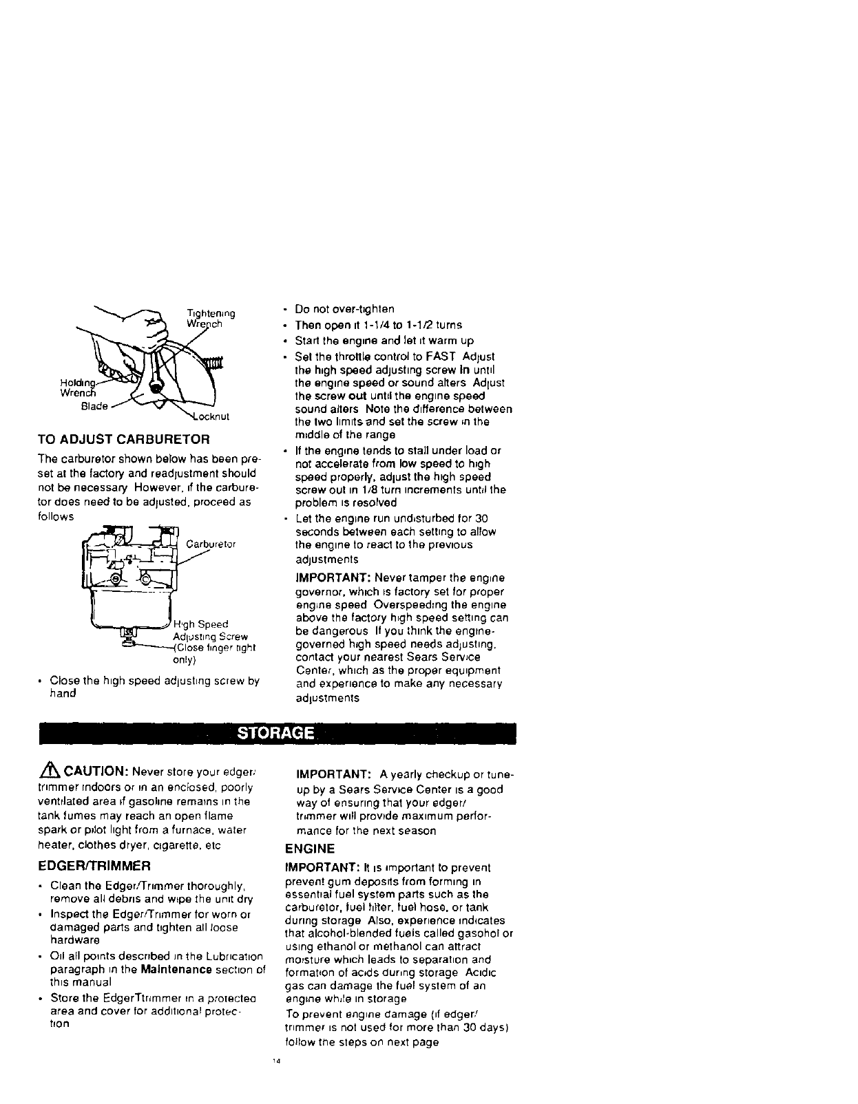
Ttghtenmg
Holdm
Wr
Blade
TO ADJUST CARBURETOR
The carburetor shown below has been pre-
set at the factory and readjustment should
not be necessary However, _fthe carbure-
tor does need to be adjusted, proceed as
follows
_ Carburetor
__l,gh Speed
Adlostmg Screw
Close finger light
only)
•Closethe h_ghspeed adjushng screw by
hand
•Do not over-t]ghten
• Then open it 1-1/4 to 1-1r'2 turns
• Start the engine and let =twarm up
• Set the throttle control to FAST Adjust
the high speed adjustmg screw In until
the engine speed or sound a_ters Adlust
the screw out unN the engine speed
sound alters Note the difference between
the two hmltsand set the screw ,n the
m_ddle of the range
• If the engine tends to stall under load or
not accelerate from low speed to h;gh
speed properly, edlust the high speed
screw out In 1/8 turn increments untd the
problem is resolved
• Let the engine run und,sturbed for 30
seconds between each setting to allow
the engine to react to the previous
adjustments
IMPORTANT: Never tamper the engine
governor, which ts factory set for proper
engJne speed Overspeedrng the engine
above the factory h_gh speed setting can
be dangerous If you think the engine-
governed high speed needs adlushng,
contact your nearest Sears Serwce
Center, which as the proper equipment
and experience to make any necessary
adjustments
,_ CAUTION: Never store your edger,'
trimmer indoors or man encbsed, poorly
ventrlated area ff gasohne remmns in the
tank fumes may reach an open flame
spark or pilot hght from a furnace, water
heater, clothes dryer, cigarette, etc
EDGER/TRIMMER
• Clean the Edger,rrnmmer thoroughly,
remove all debris and w_pe the unit dry
• Inspect the Edger/Trimmer for worn or
damaged parts and tighten all loose
hardware
• Oil all points described m the Lubncatlon
paragraph m the Maintenance sechon of
th_s manual
• Store the EdgerTtr_mmer Ena protected
area and cover for additional protec
hon
IMPORTANT: A yearly checkup or tune-
up by a Sears Sezwce Center ts a good
way of ensuring that your edger/
tr,mmer w_ll prowde maximum perfor-
mance for the next season
ENGINE
IMPORTANT: It is impertant to prevent
prevent gum deposits from forming tn
essential fuel system parts such as the
carburetor, fuel biter, fuel hose. or tank
during storage Also, expenence mdqcates
that alcohol-blended fuels called gasohol or
using ethanol or methanol can attract
moisture which leads to separahon and
formahon of acids dunng storage Acidic
gas can damage the fuel system of an
engine whle In storage
To prevent engine damage (if edger/
tnmmer _snot used for more than 30 days)
follow the steps on next page
Toremovegasohne,run the engtne
untd the tank ts empty and the engme
stops
•If you do not want to remove gasohne
a fuel stablhzer (such as Sears
Craftsman fuel stabilizer No 33500)
may be added to any gasoline left in
the tank to mlmmtze gum depas=ts
and acids If the tank is almost empty,
mix stabdlzer w_th fresh gasohne in a
separate contatner and add some to the
tank Always follow mstruct_ons on
stab=hzer container Then run eng=ne at
least 10 mJnutes after stabthzer is added
to allow mtxture to reach carburetor
Store Edger/Trimmer m a safe place See
iMPORTANT under STORAGE (EN-
GINE)
•Store the Edge/Trimmer in the wheels-
down, operating postt=on If the Edger/
Tnmmer is stored in any other pOSFt=On,o_J
from the crankcase could enter the
cylinder, causing aserwce problem
You can keep your engme _n good operating
condition durtng storage by
• Changing od
• Lubr_catmg the p_ston/cylmder area
Thts can be done by first removing the
spark plug and squirting clean engme
otl tnto the spark plug hole Then cover
the spark plug hole with a rag to absorb
oll spray Next, rotate the engme by
pulhng the starter two or three t=mes
Finally, reinstall spark plug and attach
spark plug wtre
ki_[o_oI_
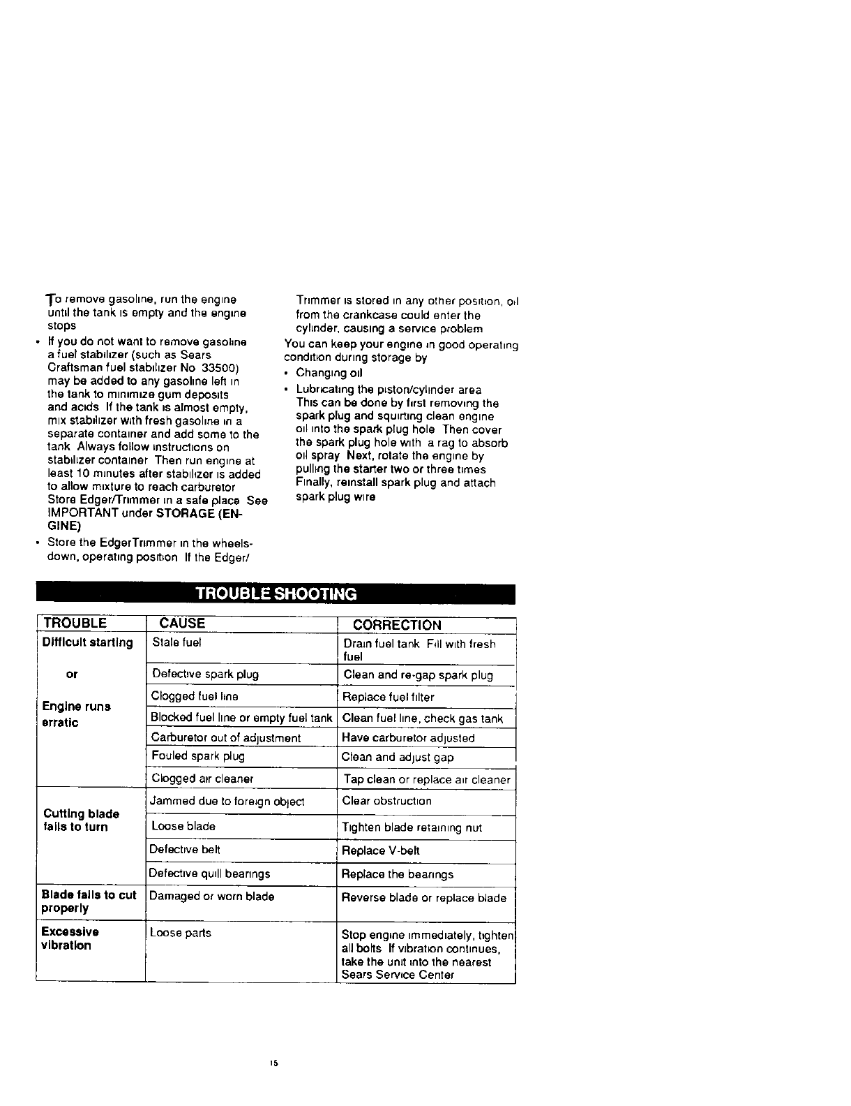
TROUBLE
Difficult starting
or
Engine runs
erratic
CAUSE
Stale fuel
CORRECTION
Dra_n fuel tank Fdl wtth fresh
fuel
Clean and re-gap spark plug
i Replace fuel filter
Clean fuel hne, check gas tank
Have carburetor adjusted
Clean and adjust gap
Tap clean or replace mr cleaner
Clear obstructton
Defectmvespark plug
Clogged fuel line
Blocked fuel hne or empty fuel tank
Carburetor out of adjustment
Fouled spark plug
Clogged atr cleaner
Jammed due to foreign object
Looseblade
Defective belt
Defective qudlbearangs
Damaged or worn blade
Cutting blade
falls to turn Ttghten blade retannmg nut
Replace V-belt
Replace the bearings
Blade falls to cut Reverse blade or replace blade
properly
Excessive Loose parts Stop enghne =mmed=ately, t_ghten
vibration all bolts If vibration continues,
take the unit into the nearest
Sears Service Center
15
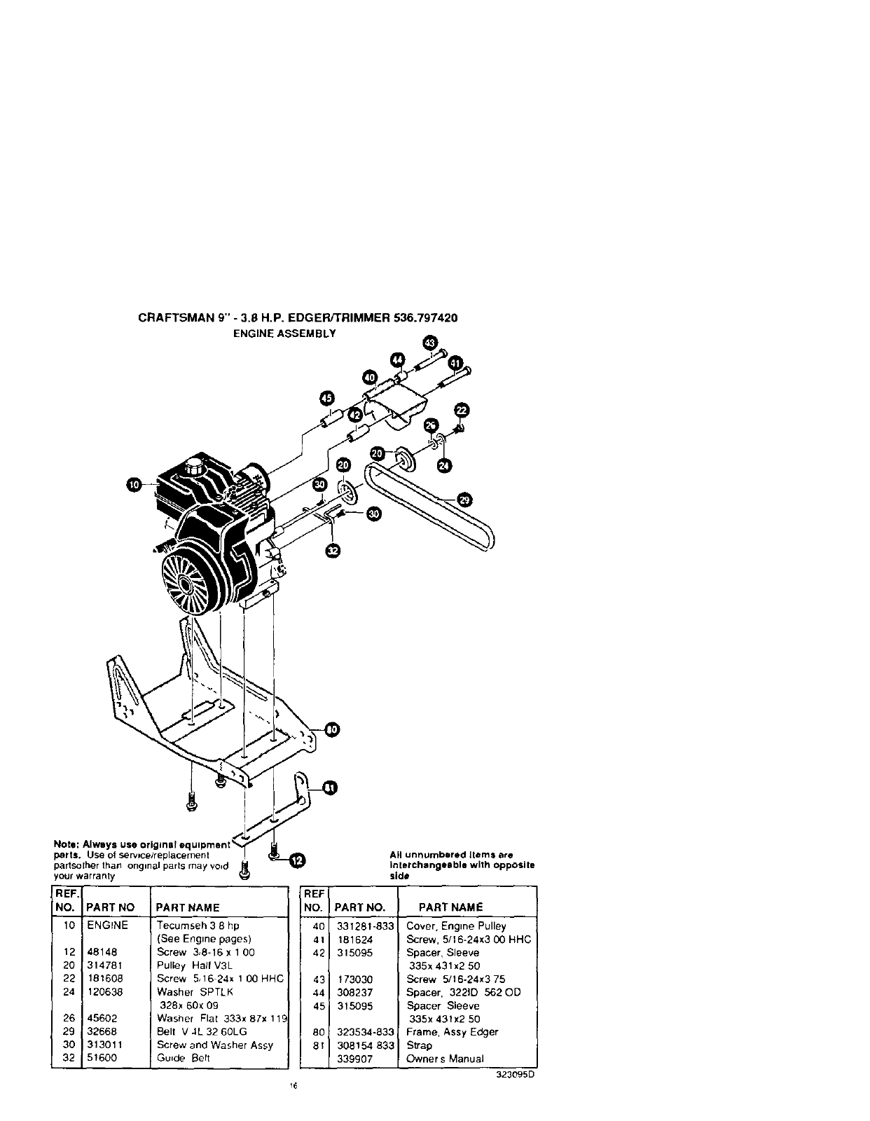
CRAFTSMAN 9" -3.8 H.P. EDGER/TRIMMER 536.797420
ENGINEASSEMBLY
Note: Always use original e,
parts, Use of servtce/replacernent
partso[her that1 original paris may void J_.
your warranty
REF.
NO. PART NO
10 ENGINE
12 48148
20 314781
22 181608
24 120638
26 45602
29 32668
30 313011
32 51600
PART NAME
Tecumseh 3 8 hp
(See Engine pages)
Screw 3,8-16 x 100
Pulley Hall V3L
Screw 5,16 24x 1 00 HHC
Washer SPTLK
328x 60x 09
Washer Flat 333x 87x 119
Belt V 4L 32 60LG
Screw and Washer Assy
Guide Bert
All unnumbered Items ere
Interchangeable with opposite
side
REF
NO. PART NO.
40 331281-833
41 181624
42 315095
43 173030
44 308237
45 315095
80 323534-833
8t 308154 833
339907
PART NAME
Cover, Engine Pulley
Screw, 5/16-24x3 (30 HHC
Spacer, Sleeve
335x 431x2 50
Screw 5/16-24x3 75
Spacer, 3221D 562 OD
Spacer Sleeve
335x 431x2 50
Frame, Assy Edger
Strap
Owner s Manual
323095D
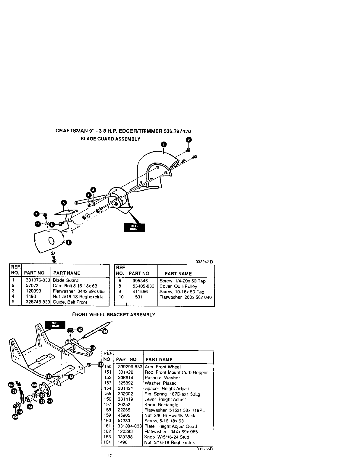
CRAFTSMAN 9" -3 8 H.P. EDGER/TRIMMER 536.797420
BLADE GUARD ASSEMBLY O
o)
0
REF
NO.
1
2
3
4
5
PART NO.
331076-833
57072
120393
1498
326748-833
332247 D
REF
PART NAME NO. PART NO PART NAME
Blade Guard 6 995346 Screw 1/4-20x 50 Tap
Carr Bolt5/16-18x 83 8 53405 833 Cover Qu_ll Pulley
Flatwasher 344x 69x 065 9 411666 Screw, 10-16x 50 Tap
Nut 5/16-18 Reghexctrlk 10 1501 Flatwasher 203x 56x 040
Guide, Belt Front
FRONT WHEEL BRACKET ASSEMBLY
REF
NO
tT50
151
152
153
154
t55
156
157
158
159
160
161
162
163
164
17
PART NO
339299-833
331422
338614
325892
331421
332002
331419
20282
22265
48905
51333
331394 833
120393
339388
1498
PART NAME
Arm Front Wheel
Rod Front Mount Curb Hopper
Pushnut, Washer
Washer P_astlc
Spacer Hetghl Adlust
Pin Spring 187D_ax1 50Lg
Lever Height Adjusl
Knob Rectangle
Flatwasher 515xl 38x 119PL
Nut 3/8-16 Hwdfllk Mack
Screw, 5116-18x 83
Plate Height Adjust Ouad
Flatwasher 344x 69x 065
Knob W/5/18-24 Stud
Nut 5/16-18 Reghexctrlk
331765D
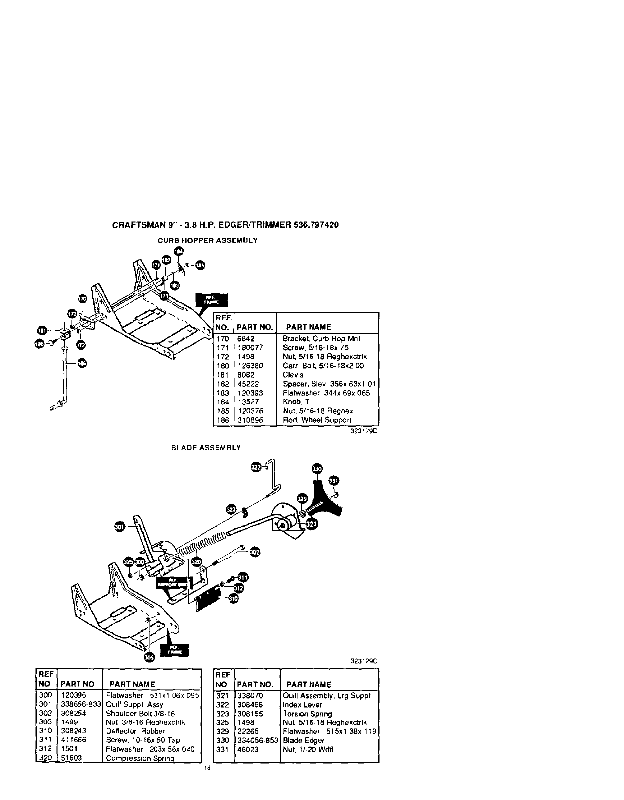
CRAFTSMAN 9" - 3.6 H.P. EDGER/TRIMMER 536.797420
CURBHOPPERASSEMBLY
REF,
NO.
170
171
172
180
_81
182
183
184
185
188
PART NO.
6842
180077
1498
126380
8082
45222
120393
13527
120376
310896
PARTNAME
Bracket, Curb Hop Mnt
Screw, 5/16-18x 75
Nut, 5/16-18 Reghexctrlk
Cart Bolt, 5/16-18x2 00
Clevis
Spacer, Slev 356x 63xl 01
Flatwasher 344x 69x 065
Knob, T
Nut, 5/16-18 Reghex
Rod, Wheel Support
323179D
BLADE ASSEMBLY
REF
NO I PART NO PART NAME
300 I 120396 Flatwasher 531xl 06x 095
301 ! 338656-833 Oudf Suppl Assy
302 308254 Shoulder Bo113/8-16
305 1498 Nut 3/8-16 Reghexctrlk
310 308243 Defrector Rubber
311 411666 Borew, 10-16x 50 Tap
312 1501 Flatwasher 203x 56x 040
320 ! 51603 Compression Sprmq
REF I
NO
321
322
323
325
329
33O
331
18
323129C
PART NO. PART NAME
338070 Qudl Assembly, Lrg Suppt
308466 index Lever
308155 Torsion Spring
1498 Nut 5116-18 Regbexclrlk
22265 Flatwasher 515xl 38x 119
334056-853 Blade Edger
46023 Nut, 1/-20 WdfI
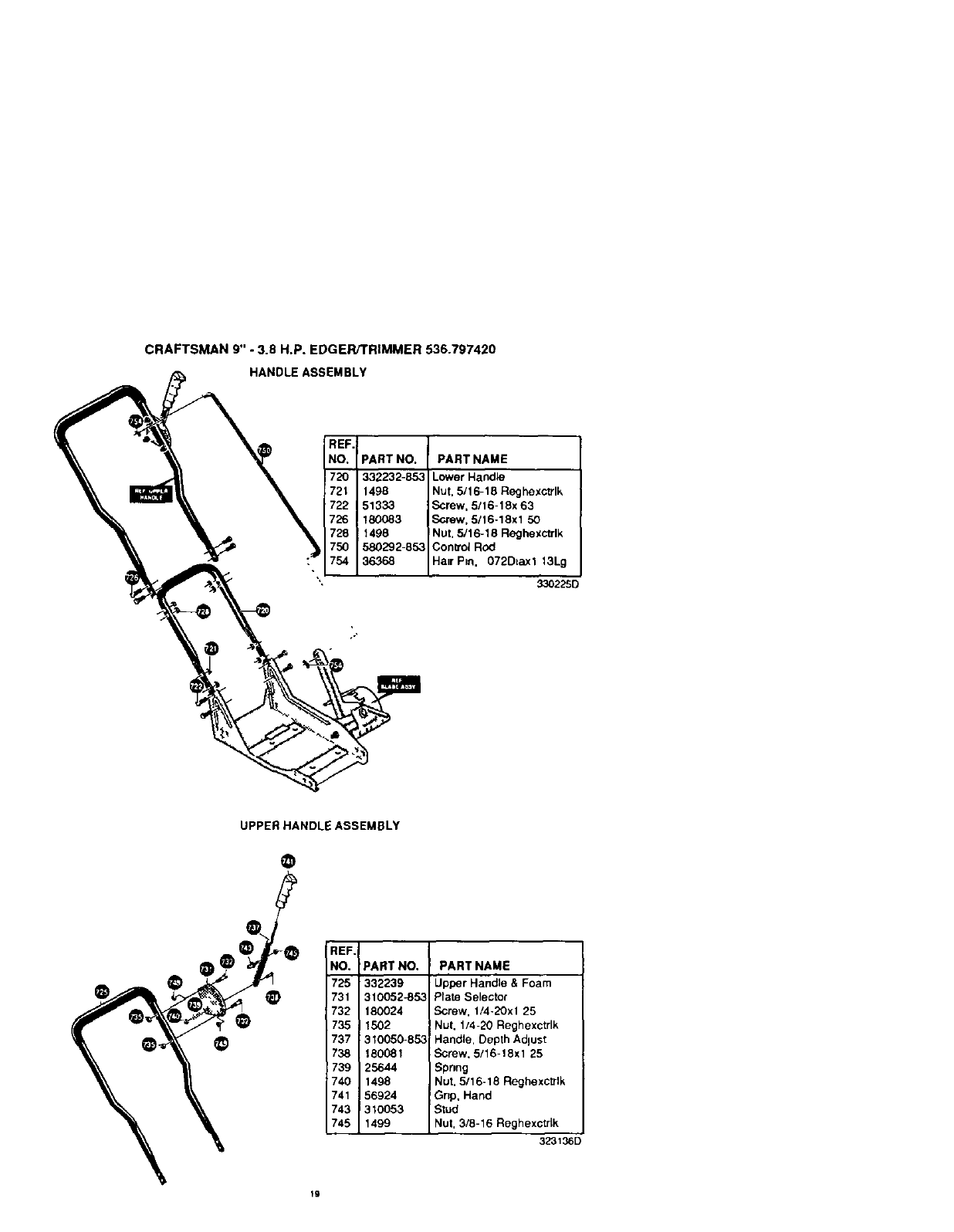
CRAFTSMAN 9" -3.8 H.P. EDGERFFRIMMER 536.797420
HANDLEASSEMBLY
REF.
NO, PART NO. PART NAME
720 332232-853 Lower Handle
721 1498 Nut, 5/16-18 Reghexctrlk
722 51333 Screw, 5/16-18x 63
726 180083 Screw, 5/16-18xl 50
728 1498 Nut, 5/16-18 Reghexctrlk
750 580292-653 Con_'ol Rod
754 36368 Hatr Pro, 072DLaxl 13Lg
3302251
UPPER HANDLE ASSEMBLY
@
REF.
NO. PART NO.
725 332239
731 310052_853
732 180024
735 1502
737 310050-853
738 180081
739 25644
740 1498
741 56924
743 31OO53
745 1499
PART NAME
Upper Handle & Foam
Plate Selector
Screw, 1/4-2Oxl 25
Nut, 1/4-20 Reghexctrlk
Handle, Depth Adlust
Screw, 5/16-18xl 25
Sprmg
Nut, 5/16-18 Reghexctrlk
Gnp, Hand
Stud
Nut, 3/6-16 Reghexctdk
323136D
\
O
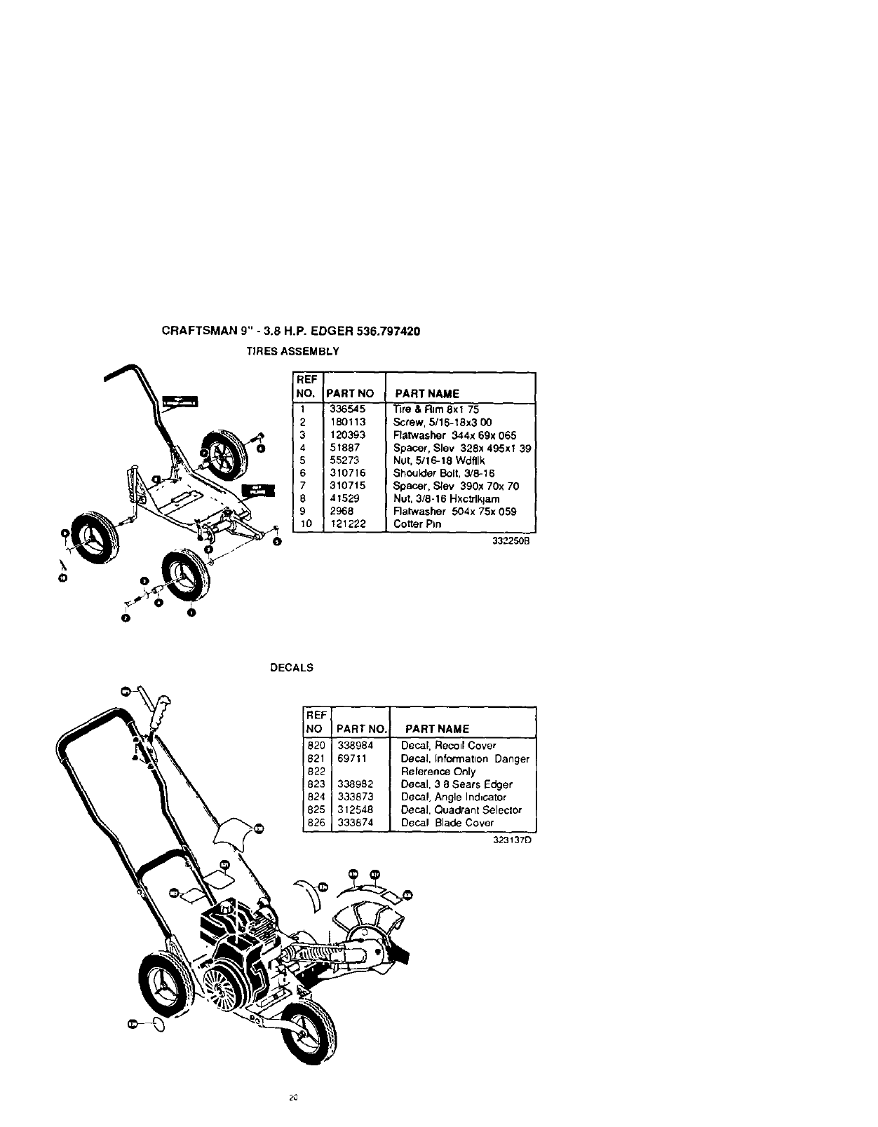
CRAFTSMAN 9" -3.8 H.P. EDGER 536.797420
TIRES ASSEMBLY
REF
NO. PART NO
1336545
2180113
3 120393
4 51887
555273
6 310716
731O715
8 41529
92968
10 121222
PART NAME
Tire & R=m8xl 75
Screw, 5/16-18x3 00
Flatwasher 344x 69x 065
Spacer, Slev 328x 495xi 39
Nut, 5/16-18 Wdfllk
Shoulder Bolt, 3/6-16
Spacer, Stev 390x 70x 70
Nut, 3/8-16 Hxc_klam
Flalwasher 504x 75x 059
Cotter Pm
332250B
DECALS
REF
NO PART NO. PART NAME
820i 338984 Decal, Recolr Cover
821 I 69711 Decal, rnformatlon Danger
338982 Decal, 3 8 Sears Edger
824 333873 Decal, Angle Ind,cator
825 I 312548 Decal, Quadrant Seleclor
826 I 333874 Decal Blade Cover 3231370
2O
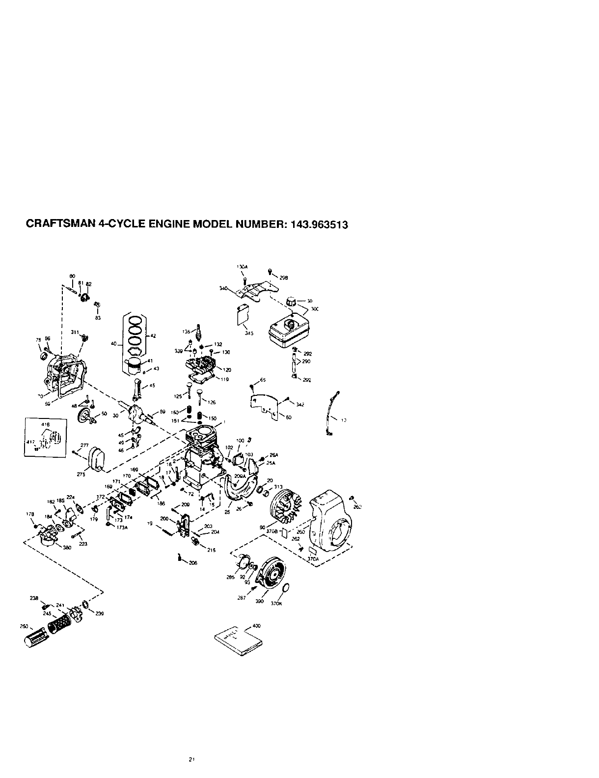
CRAFTSMAN 4-CYCLE ENGINE MODEL NUMBER: 143.963513
_T

CRAFTSMAN 4-CYCLE ENGINE MODEL
REF. REF.
NO PART NO. NO
1 36560
2 26727
14 28277
16 31334
16 31336
17 31335
18 550548
19 34593
20 32600
25 36552
25A
26
26A
30
40
41
42
43
46
46
46
49
50
60
65
68
70
72
75
80
81
82
63
86
69
90
92
93
100
102
103
_110
119
!120
125
126
126
126
130
130A
132
136
150
151
169
170
171
35883
650802
650926
35902
40020
40018
40022
20361
30963B
32610A
27241
25594
32197A
29745
650128
27677A
35863A
27642
26208
30574A
30590A
30591
30586A
650488
610961
611195
650815
650816
34443A
650872
;651007
136182
36437
36438
36471
36472
29314B
29315C
650694A
6021A
650708
33636
31672
31673
27234A
27666
31410
NUMBER: 143.963513
PART NAME
Cyhnder
Incl 2
_owel 28, 72 & 125)
Washer
Governor Rod
Govemor Lever
Governor Lever Clamp
Screw 8 32 x 6,'16"
Extensbon Spring
Oil Seal
Blower Hs_ng Baffle
(mcl 262)
Baffle Extension
Screw, 1,4-20 x 5,'8"
Screw 8-32 x 21,'64"
CrankShaft
P_ston Pin &R_ng Set(Std)
Piston &Pm Assy
_Std) [lncJ 43)
mg Set (Sld)
P_ston Pin Retam RJng
Connecting Rod Assy
_lncl 46 & 49
Connecting _od Bo_l
Valve Liher
Oil Dipper
Camshaft (MCR)
Blower Ho,Jsmg Ext
Screw 1024 x 1 2"
CylJnder Cover Gasket
Cylinder Cover (Incl 76
thfu83 311)
Oil DraJn Plug
Oil Seal
Governor Shaft
Washer
Governor Gear Assy
(Incl81 )
Governor Spool
Screw 1_4 20 x 1-1 4"
Flywheel Key
Flywheel
Bellewlta Washer
Flywheel Nut
Solid State Ignmon
Sohd Stale Mting Stud
Screw Ton(T-18 10 24
x 15;16"
Ground Wire
Cyhnder Head Gasket
Cylinder Head (_rlcJ 130)
Exhaust Valve (Std)
Inc} 161j
_xhausl Val,,e t_ '32" OS)
tlncl15_)
Intake Valve (Std)
(Incl 1511
Inlake Valve (1 32 OS)
(InCl 151}
Screw 616 16 _ 2
Screw 5 16 18x I 12
Washel
Resislor Spark Plug
(RCJ8)
Valve Spring
Valve S#nng Ca#
Valve Cover Gasket
Brealhet B_,d¥
Br ealr_.r EI_"rn_i_{
PART NO. PART NAME
34146 Valve Cover
32447 Brealher Tube
32446 Brealber Tube Grommel
30200 Screw 1_24 x 9/16"
29752 Nut & Lock Washer
1/4-28
30593 Retainer Chp
6201 Screw 1,'4 28 x 718"
26766 Carburetor to retake
pipe Gasket
36703 Inlake P=pe
(Inc1182, 184,224)
31341 Governor Link
36677 Control Bracket (Incl
203 thru 209A}
31342 Compression Spnng
650549 Screw 5-40 x 7/16"
610973 Termmaf
650139 Screw 8-32 x1/2"
30322 Losknul, 8-32
32410 Control Knob
650451 Screw 1/4-20 x1"
26754A intake Ptpe Gasket
650932 Screw 10-32 x 49/64"
34338 Arr Cleaner Gasket
35797 Air Cleaner COllar
35066 A_rCleaner Fdter
35065 Art Cleaner Cover
35585 Blower Housing
650737 Screw 1 '4-20 x 1,'2"
40000 Muller (Inc1277)
650988 Screw 1/4 20 x 2-5/16"
36467A Starter Cup
650926 Screw 8 32 x 21 '64"
29774 Fuel Line
26460 Fuel Line Clamp
660665 Screw 1_4-16 x7_8-
35591 Fuel Tank
(Incl 292 & 301)
35335 Fuel Cap
27625 Od Fill Plug
34080 Spacer
28212 Spacer
35926 Fuel Tank Bracket
650751 Screw 1/4-20 x 7/16"
32664 Baffle Heat
36261 LubdCahon Decal
35703 Control DeCal
36695 Slader Decal
640049 Carburetor (Incl 184)
590732 RewJnd Starter
36439 Gasl_el Set
36085 Spark A_reslot Kd (mcl
417J(opll
650760 Screw 8-32x3 6" (opl)
22
Th=s eng,ne COuld have been built WILl1 59073_
slarter Refer to the des=gn ol Ihe rope pulley
s1renglh ribs for part tdent=hcalion Individual starte
,arts do nol interchange
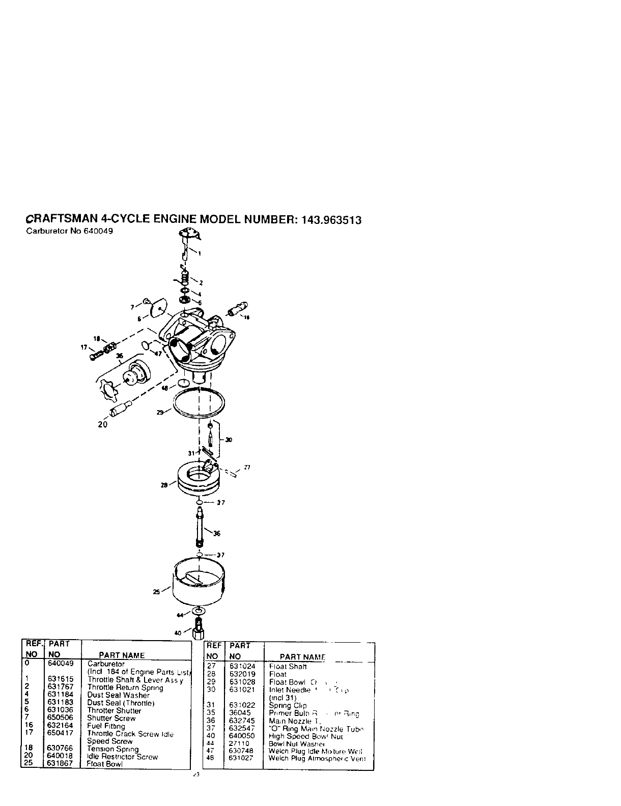
CRAFTSMAN 4-CYCLE ENGINE MODEL NUMBER: 143.963513
Carburetor No 640049
"%-%/
REF PART
NO NO
0 640049
1
2
4
5
6
7
16
17
631615
631767
631184
631183
631o36
650506
632164
;650417
_7
' --37
e,4J
REF
PART NAME NO
Carburetor 27
(Incl 184 of Engine Parts L_sl 26
Throttle Shaft & Lever Ass y29
Throttle Return Spring 30
Oust Seal Washer
Dust Seal (ThrotTle) 31
Throtter Shutter 35
Shutter Screw 36
Fuel Fitbng 37
Throttle Crack Screw Idle 40
Speed Screw 44
Tenspon Spnng 47
Idle Bestnctor Screw 48
Float Bowl
PART
NO
631024
632019
631028
631021
631022
36045
632745
632547
640050
27110
630748
631027
PART NAME t
Float Shail
Float
Float Bowl 0:
Inlet Needle _ ( , _
_ncl 31 )
pnng Cl*p
Pnmer Bulb _q P, ,q,r,_
Mare Nozzle T.
"O" Ring Ma,n Nozzle Tub,,
High Speed Bow _Nut
Bowl NuI Washer
Welch Plug Icfle Mixture W_']I
Welch Plug Atmosphe*,c Veto
18 630766
20 64O018
25 831867
z3
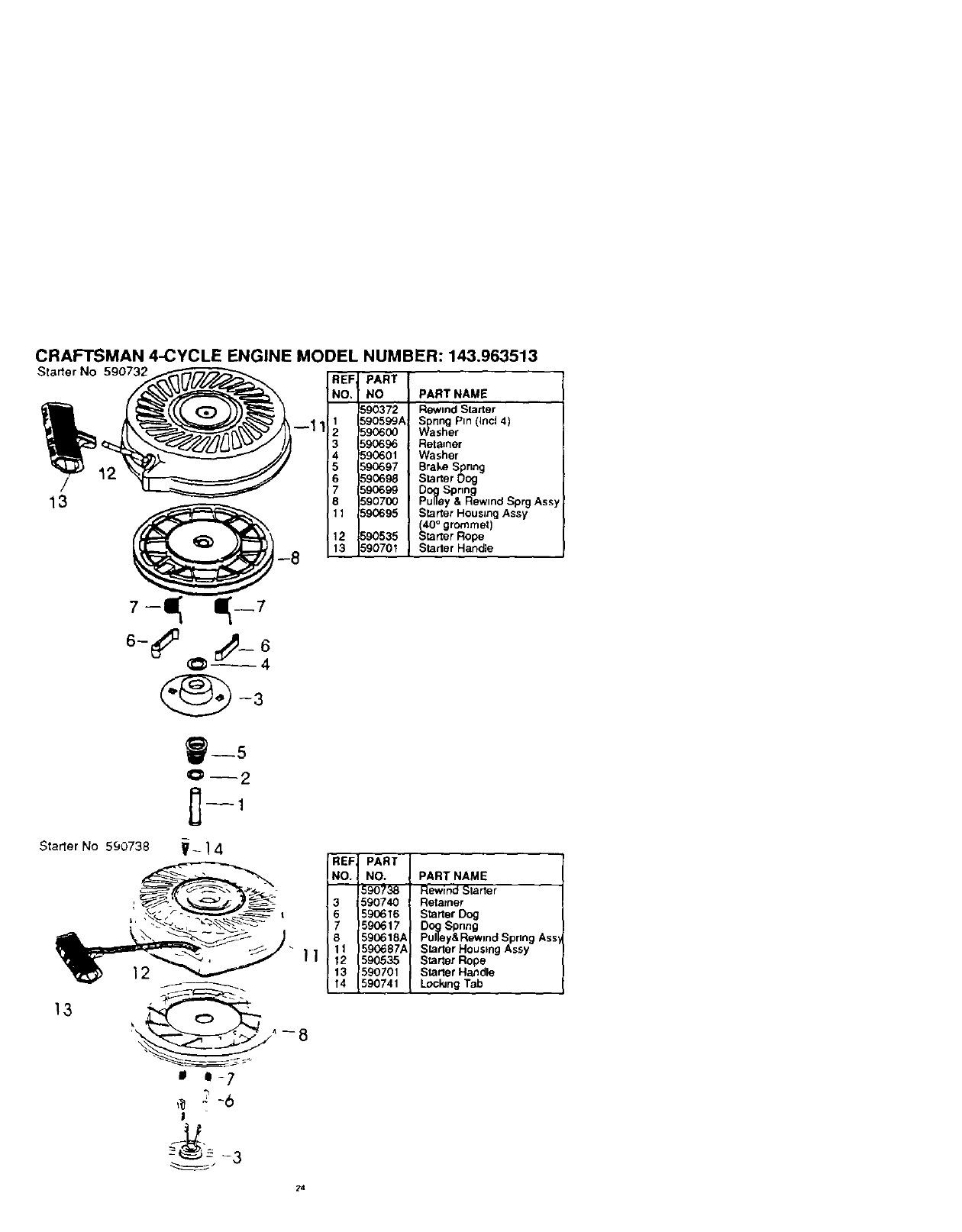
CRAFTSMAN 4-CYCLE ENGINE MODEL NUMBER: 143.963513
/
13
Starter No 590732 _--1 1
REF, PART
NO. NO PART NAME
590372 Rewmd Starter
1 590599A WashrSpnngeP'n((nc(4)
2 590600
3 590696 Retainer
4 590601 Washer
5S90697 Brake Spring
6 590698 Starter Oog
7 590699 Dog Spnng
8 590700 Pulley &Rewtnd Sprg Assy
11 590695 Starter Housing Assy
(40° grommet)
12 590535 tstarter Rope
13 590701 Starter Handle
_--5
O-- 2
Starter No 590738 V- ] 4 REF, PART
NO. NO. PART NAME
590738 Rewind Starter
3 590740 Retarner
I6 590616 Starter Dog
7590617 Dog Spnng
590618,_ Pulley&RewmdSpnng Ass,
Starter Housing Assy
" 11 590687¢
| ] 12 590535 Starter Rope
12 13 590701 starter Handle
_14 590741 Lockmg Tab
13
' "-.----_J_^7 _ --8
mi- 7
!
_---__ -3
24
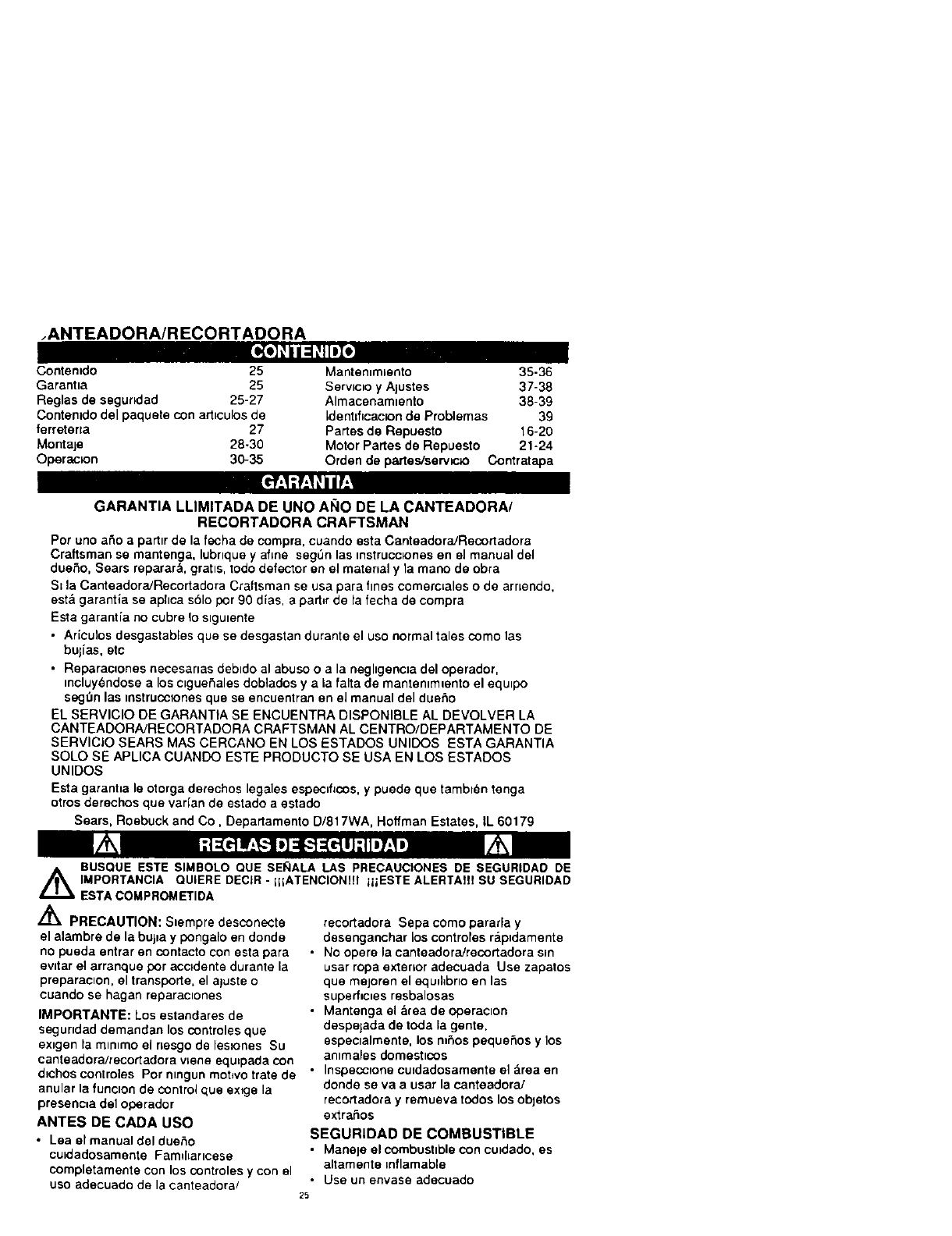
.ANTEADORA/R ECORTADORA
Ko]OlI=!_IIDZe
Contentdo 25 Mantemmbento 35-36
Garantia 25 Serwmo y Ajustes 37-38
Reglas de ssgundad 25-27 Almacenam=ento 38-39
Contentdodel paqueta con art_culosde [denttflcac_onde Problemas 39
ferretena 27 Partes de Repuesto 16-20
Montaje 28-30 Motor Partes de Repuesto 21-24
Operaclon 30-35 arden de partes,'serwc_o Contratapa
GARANTIA LLIMITADA DE UNO ANO DE LA CANTEADORA/
RECORTADORA CRAFTSMAN
Par uno a_o a parttrde la fecha de compra, cuando esta CanteadoradRecortadora
Craftsman se mantenga, lubnqueyafine segt_nlas instrucc_onesen el manual del
dueSo, Sears reparar&, gratts,todo defector en el material y la mano de obra
St la CanteadoraJRecortadora Craftsman se usa para fines comerc=aleso de arnendo,
est& garantla se aphca s61opor 90 d{as, e part_rde la fecha de compra
Esta garantia no cubre to slgutente
•Aricutos desgastables que se desgastan durante el uso normal tales como las
bulias, etc
•Reparaclones necesarles debtdo al abuso o a la neghgencla del operador,
mcluy6ndosealos clgueSales doblados y a la falta de mantenlmlento el equlpo
segt3nlas mstruccvonesque se encuentran en el manual del dueSo
EL SERVlClO DE GARANTIA SE ENCUENTRA DISPONIBLE AL DEVOLVER LA
CANTEADORA/RECORTADORA CRAFTSMAN AL CENTRO/DEPARTAMENTO DE
SERVIClO SEARS MAS CERCANO EN LOS ESTADOS UNIDOS ESTA GARANTIA
SOLO SE APLICA CUANDO ESTE PRODUCTO SE USA EN LOS ESTADOS
UNIDOS
Esta garanha le otorga derechos legales especff_cos,ypuede que tambt_n tenga
otros derechos que varian de sstado aestado
Sears, Roebuck and Co, Departamento D/817WA, Hoffman Estates, iL 60179
_ESTA COMPROM ETIDA
/_ PRECAUTION: Slempre desconecte
el alambre de la buj=a y pongalo en donde
no pueda entrar an contacto con ssta para
evdar el arranque par accidents durante la
preparecton, el transports, el aluste o
cuando se hagen reparactones
IMPORTANTE: Los estandares de
segundad demandan los controles que
exigen la mlmmo el nesgo de leslones Su
canteadoraJrecortadora vlene equ=pada con
d_chos controles Pot nlngun mobvo trate de
anular le funclon de control que sx_gs la
presenc=a del operador
ANTES DE CADA usa
•Lea el manual del dueho
culdadosamente Famfl=arlcese
completamente con los controles ycon el
usa adecuado de la canteadora/
BUSQUE ESTE SIMBOLO QUE SE_ALA LAS PRECAUCIONES DE SEGURIDAD DE
IMPORTANClA QUIERE DECIR - IHATENCIONUI iiIESTE ALERTAIII SU SEGURIDAD
recortadora Sepa como pararla y
desenganchar los controfes r&pldemente
No opere la canteadora/recor_adora sin
usar ropa exterior adecuada Use zapatos
que mejoren el equlhbrto en las
superfic=es resbalosas
Mantenga el &rea de operacton
despejada de toda la genre.
espectalmente, los m6os pequeSos y los
antmales domesttcos
Inspeccpone cu_dadosamente el &reaen
donde se va a usar la canteadora/
recortadore y remueva to(los los objetos
extraSos
SEGURIDAD DE COMBUSTIBLE
•Manaje el combusttblacon cu_dado,es
altamente mflamable
•Use unenvase adecuado
25
•Rewse el Sumln_stro de oombust=ble antes
de cada use, perm=t_endoque exJsta
espacio para la expans=bn pues el calor del
motor y/o sol pueden hacer que se expanda
el combustible
*Llene el estanque de combustible afuera
con touche coJdado Nunca Ilene el
estanque de combustible en rec=ntos
cerrados. Vuelva a colocar ]a tape del
estanque de combustible en torma segura y
hmpm el combustible derramado
• Nunca remueva ia tape de[ estanque de
combustible o agregue combustible aun
motor que est& funaonando e que esta
caltenIe.
•Nunca almacene combustible o la
canteadora/recortadora con combust=bte en
el estanque denim de un edlflcJoen donde
los gases puedan alcanzar una llama
expuesta
SEGURIDAD DE OPERACION
• Nunca perm_ta clue los nines o
adoJescentes 16venes operen su
canteadora/recortadora Manlengalos
elejados cuando est_ en operac_on Nunca
perm=ta que los adultos operen la
canteadora/reoortadora s_nlos
conocJm_entos adecuados
•No opere la m&quma Si esta tomando
drogas u otras med_c_nasque pud_era
causer somnolenoa o que pudleran afectar
su hablhdad pare operarat esta maqulna
• No opere esta m&quma sl su estado
emo(:lonar oflsICO no Je permute operarla
con segundad
• Slempre use anteojos de segundad o
prolecclones para los ojos durante {a
operacw6n o cuando haga alustes o
reparaoones para proteger sus OlOScontra
obfetos extraC_osque la canteador&
reconadora pueda lanzar
• No ponga tas manes n_ los p=es cerca o
debalo de partes rotatonas
•Tenga sumo culdado cuando opere o
atrawese entradas de autombvfles de r_p_o,
senderos o carnlnos Man[_ngase alerta
de pelJgrosescond[dos o traflco
•Tenga culdado pare eviler resbalarse o
caerse
•Nunca opere la canteadora,'reoortadora s=n
las protecclones y las planchas adecuadas,
os_notros dlspOsltos de protect=on de la
segurtdad en su lugar
•Nunca opere la canteadora, recortadora a
alias velocrdades de transporte en
superficies resbalosas M_re hac_a a[ras y
tenga ¢uldado cuando retrocede
• Nunca permJta la presenc_a de
espectadores cerca de Ja canteaaora
recorladora
• Mantenga a Josnlt_Osy a los ammales
dom_stlcos alejados m_entras se es[e en
operac_bn
• Nunca opere la canteadoraJrecortadora s=,
buena v=s=bflldado tuz
•No haga luncJonar el motor en recmtos
cerrados Los gases de escape son
pehgrosos (contlenen MONOXIDe DE
CARBONO, UN GAS SIN OLOR QUE
CAUSA LA MUER'rE)
•Tome todas las precauc=ones pos_bles
cuando deje la canteadora/recortadora
desatendtda Pare el rr_or
•No sobrecargoe la capaodad de la
canteadoraJrecortadora l_atando de cantear
muy profundarnente a mucha veloc_dad
ALMACENAMIENTO CON
SEGURIDAD
• S_empre re_ase a_a secc_6n de
almacenam_ento dal manual del duer_o
para venficar los detalles de
importanoa slla canteadora]
recortadora se va a elmacenar per un
largo penodo de t_empo
•Nunca almacene la ¢anteadora/recortadora
con combusbble en el estanque de combus-
t*bJedentro de un edd_c_oen deride se
encuentren presentes fuentes de _gmoon,
tales come los caientadores de agua o del
amb=ente, secadoras de rope y otros
anefactos parec=dos Permlta que se enfr[e
el motor antes de guardado en algun lugar
cerrado
•Mantenga la canteadora/recortadora en
condJc=ones de trabaJo seguras Revise
lodes los suJetadores amtervelos frecuentes
pare ver=f=carsJest&n apretados en forma
segura
SEGURIDAD DE REPARACIONES/
AJUSTES
•Despu_s de pegarle a objeIos extrafios, pare
el motor Remueva el alambre de la buJ_a,y
mantengato aJejado de _sta para ewtar el
arranque per acc=dente Inspecc_one
cuJdadosamente la canteadora/recortadora
para verJficar Slesta daf_ada y repare los
dafios antes de volver a arrancar y operar la
canleadoraJrecortadora
•S_[a canteadora/recortadora empleza a
v_brar anormalmente, pare el motor y revise
mmedlatamenle la cause La vlbrac_bn,
normalmenle es un awso de problemas
• Pare ra cuch_lla _ando abar_done la
pos_cJonde operacJon Tambl_n, pare el
motor y desconecte el alambre de la bul_a
antes de des[aponar la cuchflla y cuando
haga reparac_ones, ajustes Oinspecctones
• Cuando haga hmp_ezas, reparacJones o
respect=ones, apague el motor y asegurese
que todas las pades en mov=mlento se
hayan deten_do
•Nunca trate de hacer ajustes mlentras el
meier est_ funclonando {excepto cuando
especfflcamente Io recorn_ende el
fabrJcante)
26
Z_ ADVERTENCIA: Esta unldad vtene
equ_pada con un motor de combUStl_)nmterna
yno se debe usar sobre, o cerca, de un
terreno no desarrollado CUblerto de bosques,
de arbustos ode c_sped, a menos que el
s_stemade escape del motor venga equ_paclo
con un amortlguador de chispas que cumpla
con las 1eyes locales oestata]es (st ex_sten) SJ
se usa un amorttguador de chtspas, el
operador debe mantenerlo en condtctones de
trabajo eficlentes
En el estado de California, la ley extge Io
antertor (Secclbn 4442 del "Cahiorma Public
Resources Code" (Decreto de P,ecursos
Publlcos de Cahfornta) Otros ,}stados pueden
confer con otras leyes parecldas Las 1eyes
federales se aphcan en las tterras federales
Su Centro de Servlc_oAutorlzado Sears m&s
cercano t_ene dlsponible un amortlguador de
ch=spawstlenaador (yea la seccibn "PARTES
DE REPUESTO" en este manual)
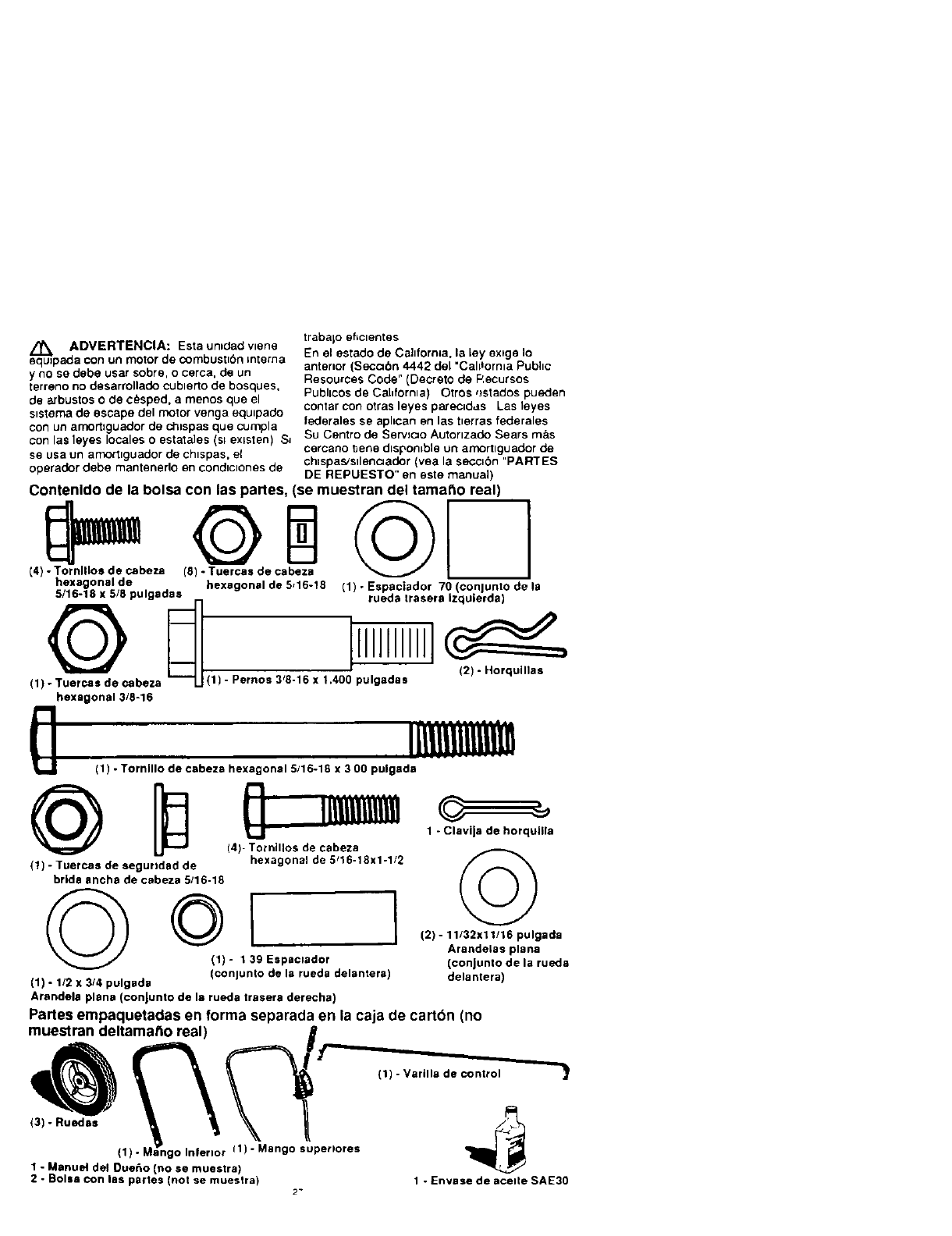
Contenldo de la bolsa con las panes, (se muestran del tama_o real)
(4) _heza (SQe cate_z a _ I
hexagonal de hexagonal de 5,16-18
5/16-18 x 5/8 pulgadas
(1) - Tuercaa de cabeza
hexagonal 3/8-16
(1) -Espaciador 70 (oonjunto de la
rueda trasera Izqulerda)
12) - Horquinas
-Pernos 3'8-16 x 1.400 pulgadaa
(1) - Tornlllo de cabeza hexagonal 5/16-18 x 3 00 pulgada
rt ...........
! ! Illl!llll!ll!!
Lit
(4)- Totnillos de cabeza
(1) - Tuercas de segurtdad de hexagonal de 5_16-18x1-1/2
bride encha de cabeza 5/16-18
(1)- 139Espaclador
(conlunlo de la rueda delantera)
I
(1) -1/2 x 3/4 pulgada
1-ClaviJa de horqullla
©
(2) -11/32x11/16 pulgada
Arandelas plane
(conJunto de la rueda
delantera)
Arandela plane (conJunto de la rueda trasera derecha)
Partes empaquetadas en forma separada en la caja de cartbn (no
muestran deltamatto real) B
(1) -Mango Inferior 11)- Mango superlores
1 - Manue! del Duello (no se muestra)
2 - Boise con lea partes (not se muestra) 2" 1-Envase de acelte SAE30

A
/rk PRECAUCION" Slempre use
ateojos de segurldad o proteco=on para
los ojos cuando monte fa canteadora!
recortadora
HERRAMIENTAS NECESARIAS
PARA EL MONTAJE
2-Llaves de 1/2 pulgada
(o Ilave ajustable)
2 - Llaves de 9/16 pulgada
(o Ifave ajustable)
2 - Llaves afustable
1-Aheates
1-Desatorntllador de hoja plana
La muestra la canteadora,'recortadora
completamente montada
Las referenclas allado derecho y al lado
_zquJerdo de ta canteadora/recortadora son
desde In pos_cton del operador detras de la
unldad
PARA REMOVER LA
CANTEADORA/RECORTADORA DE
LA CAJA DE CARTON
•Remueva el mango inferior, vardla de
control, mango superior y el mater_al de
empaque de la eara de carton
•Corle Jas cuatro esqutnas de la cala de
carton
• Remueva el empaque de la cuchIta de
la eanteadorarrecortadora
PARA MONTAR LA CANTEADORA]
RECORTADORA
AVISO El mango mfenor debe ajustarse
prlmeropues es d_fJCllde adjuntarlo cuando
las ruedasestan puestas
•Ponga el mango inferior dentro del
bastJdor de la canteadora/recortadora,
yea contmuaclon figura y asegurelo en
su lugar con cuatro torndlos de brlda
ancha, de cabeza hexagonal de 5/16-IB x
5/8 pulgadas y cuatro tuercas de
segurtdad, de cabeza hexagonal de
cabeza hexagonal de 5/16-18 que se
encuentran en la bolsa con las partes
Las tuereas de segur_dad se deben
encontrar inferior de los dos mangos.
seg_n mueslra tn mtddle ftgura de pagma
• Adjunte la rueda Irasera deracha a la
vartlla del soporte de [a rueda de la
canteadoratrecortadora segun muestra
28
inferior f_Jura con una arandela plana de
1/2 x 3/4 puk3ada y con la clawja de
horqudla que se eneuentran en la bolsa
con las partes Separe los extremos de la
elawla hend_a para asegurarlo en su
lagar
_,palanca derembrague
control
Protection de la
superior
Mane
arrancador
5/16-18 X 5/_
Tormllos de brJde
ancha de ¢abeza
hexagonal
Mango mfertor
5/16-18_
Tuercas de
_._=lDcabezahex
VISTA DESDE EL I-ADO DERECHO
Arandela plana
1/2x314 inch
Clavtl
Horqudla

•Adlunte la rueda trasera qzqu_erda a la
eanteadoraL_recortadora fonclon en figura
abalo con un perno de resalto de 3/8-16
x 1 40 pulgadas, un espac_ador (0 07
pulgada de Iongrtud) y una tuerca de
cabeza hexagonal de 3/8-16 que se
encuentran en la bolsa con 1as partes
VISTA DESDE EL LADO IZQUIERDO
Espac_ader
( ades de Iong_tud)
Perno con resalto
Basbdor _,
Cabeza
3/8-16
• AdJunte la rueda delantera a la
canteadora_recoltadora fortolon en hgura
abaJo con un tornlllo de cabeza hexago-
Nal de 5/16-18 x 3 00 pulgadas dos
arandelas planas de 11 ,_32 x 11/16
pulgadas, un espaciador y una luerca de
segurldad de brida ancha de 5/16-18 qua
se encuentran en Ja bo[sa con las parles
VISTA DESDE LA PARTE DELANTERA
Tuerca de
segundad de
bnda ancha
_5/16-18x3
adecuada Jnsetta un extreme de la vanlla
de control, desde la izqulerda a la
derecha, a tray,s del agujero en la
palanca del embrague y adl0nlelo con
una horqull[a qua se encuentra en [a
bolsa con las partes Yea proximo hgura
•Ponga _a palanca del embrague en la
pnmera profundidad selecc_onable e
inserla el otto extreme de la vardla de
CONtrol a traves del agujero del braze de
soporle del cuerpo Adl0ntela con la
horquilla qua se encuentra en ]a bolsa con
las partes Vea proximo llgura
• Mueva la palanca del embrague ala
poslcion m_ls trasera pOslble (NEUTRO) y
aseg0rela Yea el arise a contmuaoi6n
• En el case de qua sea dlf{ciI hacer que la
palanca del embrague se meta en
NEUTRO, puede ser necesarlo soltar los
cualro tornlllos y tuercas qua suletan los
mangos mferlores al bashdor, yea hgura
pagma 30 Palanquee (hacla adelante) los
mangos, solo Io sufic=ente para perm_tlr
qua la palanca del embrague entre
hbremente a la pos]clon de NEUTRO
Vuelva a apretar las tuercas y los tornlllos
Cuando la palanca del embrague esta en
la poslclbn de NEUTRO el Braze de
Soporte del Cuerpo tlene que estar en
contra del espaclador y del tormllo detras
de este Vea la figura insertada abalo
Mango Supenores
(an la poslcmn del
cleo embrague
plana plana
11/32xl 1/16
cabeza
hexagonal I1 39 pulgadalongltud)
5/16-18x3
• Ponga el mango supenor en el mango
mfenor ace tunct6n de proximo hgura
ahnee el mango superior con los dos Tuercas de
aguleros supertores en el mango inferior Y c_ezaSeurided de
asegurelo en su lugar Con quatre tornlllos hexa_
de cabeza hexagonal de 5/16-18 x 1-114
pulgadas yquatre tuercas de segurldad,
de cabeza hexagonal de 5/16-18 qua se Mango ,'
encuentran en la bolsa con las partes mfenore
Las tuercas de segundad se deben I Brazode
encontrar en la parte interior de los dos t
mangos, segun se muestra de proximo
•La palanca del embrague esla ublcada en
el lade _zqulerda del mango superior
cuando se ha instalado en forma
29
hexagonaJ de
5/16-18
e control
Braze de
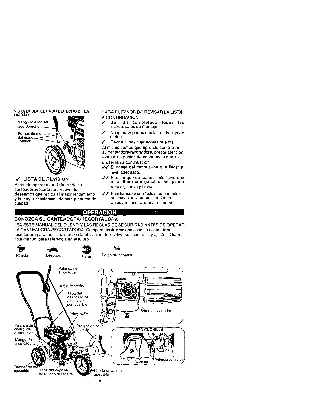
VISTA DESDE EL LADO DERECHO DE LA
UNIDAD
Mango Infer=or del
Pernos de rnon_aje
del man
inlerlor
i/' MSTA DE REVISION
Antes de operar y de d=sfrutar ,de su
eanteadora/recortadora nuevo, le
deseamos que recJba el mejor rend_m_ento
y ia mayor satlsfaccEon de este producto de
calrdad
HAGA EL FAVOR DE REVISAR LA LIs"r,4
A CONTINUACION
,/ Se han completado todas las
_nstruco_ones de montaje
,/ No quedan partes sueltas en la caja de
carton
,/ Revise sJ hay sujetadores sueltos
AI m_smo tlempo que aprende como usar
su canteadora/recortadora, preste atencton
extra alos puntos de importancla qua se
presentan a continuation
4',/" El aaerte del motor {lane qua Ilegar al
nlve[ adecuado.
,/J El asta_lque de combustible Ilene qua
estar llano con gasohna sm plomo
regular, nueva y hmp=a
J,/ Famlhancese con to,dos los controles -
su ub_cacion ySU funclon Operelos
antes de hacer arrancar el motor
o] -J=!:r:_ tel _
CONOZCA SU CANTEADORA/RECORTADORA
LEA ESTE MANUAL DEL DUEF_OY LAS REGLAS DE SEGURIDAD ANTES DE OPERAR
LA CANTEADORA/RECORTADORA Compare lae ,lustrac_ones con su canteadora_
recorladorapara famdlarlzarse con la ublcac_onde losd_versoscontrolesy ajustes Guarde
este manual para referenc_aen el futuro
R&pJde DespacJo Parar 14
goton del cebador
Palanca de
control de
ace{eracion
Mango (
aluslable
embrague
Vat,lie de control
Tapa del
oesposito de
relleno del
Sdenc_ador
Protect=on de la
cuchllla VISTA CUCHILLA
Ind_G(_
de retleno del ace*re alustab[e
3o

"Control de la aceleraclon - Se usa para
controlar la veloc_dad del motor
Boton del cebador - Inyecta combustible
dlrectamente an el m_Jltrple del carburador
para arranques m_s r&p_dos
Mango del arrancador - El motor de esta
canteadora] recortorador wane equ_pado
con un arrancador de culateo de bro facd
Palanca del embragua -Se usa para
hacer arrancar y parar la cuchllla ycontrolar
la profund_dad del corte
Palanca de Indlce - Perm=ta el ajuste
desde la poslc=bn de canteado (vert=cal) ala
de recorte (honzontal) Para cambrar de
pos_c=bn, t=re la palanca de ind=ce yrote el
conlunto del cuerpo al &ngulo o a la
pos=c=6ndeseada
Protecclon de la cuchilla -Se usa para
ev=tar qua las p=edras yotros mater=ales
sean lanzados hacla el operador
Rueda trasera ajustable - La rueda trasera
derecha as ajustable para saltar sobre la
aeera (para mvelar la eanteadora_
reeortadora cuando se cantea a Io largo de
la acara)
Ruada dalantera aJustable - La rueda
delantara es ajustable de lado para
balaneear TambJen, se peude ajustar hac_a
abalO para subJrse por el franco de la acera
(para n_velar la conteadora/recortadora
cuando se este canteando a Io largo de la
acara).
COMO USAR SU CANTEADORA/
RECORTADORA
Z_ PRECAUCION La operaclon de
esta canteadora/recortadora puede hacer
qua salten objetos extraSos dentro de sus
ojos, Io qua puede produclr daf_os graves
en estos S_empre use anteojos de
segundad oproteomones para los ojos al
operar ra canteadora/recortadora
Recomendamos el uso de anteojos de
segurrdad estandar o la Mascara de
Segundad de V=s=onAmpha, para uso sobre
los espejuelos
PARADA
• Para parar el motor, asegurese que la
palanca del ernbrague este
completamente hasta atras (o hac=a
arnba) y mueva la palanea de control de
la aceleracron ala poslclon de PARADA
PRECAUClON: Nunca deje la
canteadora/recortadora desatend_da
m_entras qua el motor estafunctonando
31
Stempre desanganche la cuchdla de torte y
pare el motor
PARA USAR EL CONTROL DE LA
ACELERACION
• Haga funclonar el motor a veloc=dad
completa durante el uso normal
• Empule la palanca de control de la
estrangulaclbn hac=a arr_ba para
aumentar le velocsdad, hacla abajo para
dlsmlnulr la velocldad
PARA USAR BOTON DEL CEBADOR
• Mueva la palanca de control de la
aeelerac=bn, yea pagrna 30 a la posse=on
de FUNCIONAMIENTO (RUN)
•Empu]e el botbn del cabador crnco
veces.'vea pagma 30 Espere
alrededor de dos segundos entre eada
empujon
•No use el cebador para volver a
arrancar un motor cahente despues de
una parada corta
PARA USAR PALANCA DEL
EMBRAGUE
• Haga arrancar el motor ymeuva la
palanca del embrague hac_a adelante
(o hacla abajo) para enganchar La cuchdla
do corte
• SeleceJone la profundldad del canteo
que necos=ta Hay cmco selecclones
hasta 2-3f4 pulgadas de profundldad
IMPORTANTE: En el caso de que se
neces_te cantear con mucha
profund_dad, recomendamos qua
prtmero sa haga un corte menos
profundo, luego cortes amas
profundrdad hasta qua se Iogre la
profund=dad deseada
PARA USAR PALANCA DE INDICE
(OPERACION DE RECORTE)
• Pare el motor y desconecte el alambre
de la bujla
• Suelte la manllla, yea figura, en el brazo
de la rueda delantera y deshce las
ruedas, comptetamente, hac_a el lado
derecho
•Apnete la mamlla en forma segura
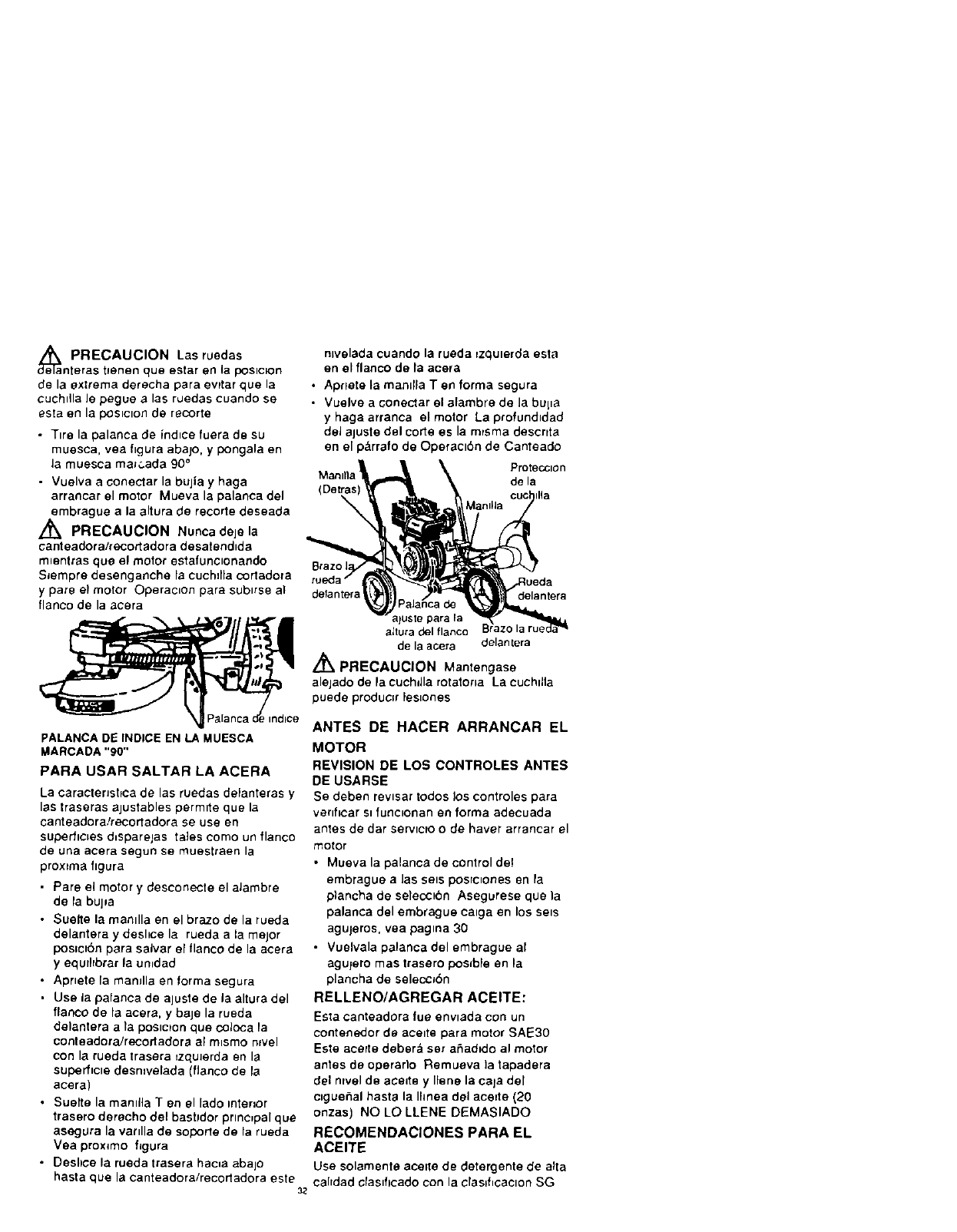
_a PRECAUCION Las ruedas
nteras tfenen queestar en la poelc_on
de la extreme derecha para evrtar qua la
cuchdla le pegue alas ruedas cuando ee
esta en la poslclon de recorte
•Tire la palanca de induce fuera de su
muesca, yea figure abe]o, y pongala en
Ja muesca ma_,:,ada 90 °
• Vuelva aconectar la bujia y haga
arrancar el motor Mueva la palanca del
embrague ala altura de recorle deseada
,_ PRECAUCION Nunca deje la
cant eadora/recort adora desatend_da
m_entras que el motor estafunclonando
SJempre desenganche la cuchdla cortadora
ypare el motor Operae_on para sublrse aT
fiance de la acera
PALANCA DE INDICE EN LA MUESCA
MARCADA "90"
PARA USAR SALTAR LA ACERA
La caracterJshoa de las ruedas delanteras y
lee traseras ajustables permlte que la
canteadora/recortadora se use en
superflc=es d_sparejas tales come un fiance
de una acera segun se muestraen la
proxtma figure
•Pare el motor y desconecte el aJambre
de la bujla
•Suelte la mandla en el braze de la rueda
delantera y deshce la rueda ala major
poelel6tl para salver el fiance de la acera
yequrl_brar la umdad
• Aprlete la manJlla en forma eegura
• Use la pafanca de aluste de la altura del
fiance de la acera, y baje la rueda
delantera ata pos_cton qua coloca la
conteadora/recortadora al m_smo nwel
con la rueda trasera =zquJerda en la
superficle desn=velada (fiance de la
acera)
• Suette la mamila Ten el lade interior
trasero derecho del baetldor principal qua
aeegura la vardla de soporte de la rueda
Vea prox=mo figura
•Deshce la rueda trasera hac=a aba]o
hasta que la canteadora/recortadora este
nlvelada cuando la rueda =zqulerda esta
en el fiance de la acera
•Aprtete la mamlla Ten forma segura
•Vuelve a conectar el alambre de la bupa
y haga arranca el motor La profund=dad
del aluste del corte es la mrsma descrtta
en el p_rrafo de Operacl6n de Canteado
Protection
de la
ilia
defanter_
ajuste pare fa
altura del fiance
de la acera delan[era
//_k PRECAUCION Mantengase
alejado de la cuchdla rotatorla La cuchllla
puede loroduc_rles_ones
ANTES DE HACER ARRANCAR EL
MOTOR
REVISION DE LOS CONTROLES ANTES
DE USARSE
Se deben revlsar redes los controles para
verff_car s_fune_onan en forma adecuada
antes de dar serv_cro o de haver arrancar el
motor
• Mueva la palanca de control de!
embrague a Jas SelS poslclortes en ra
p)ancha de selecct6n Asegurese que ia
palanca del embrague calga en los sale
agujeros, vea paglna 30
• Vuelvala palanca del embrague at
agulero mas trasero poslble en la
plancha de selecci6n
RELLENO/AGREGAR ACEITE:
Esta canteadora rue enviada con un
conterledor de acelte para motor SAE30
Eete acatte deber_l set a_ad)do al motor
anles de operarlo I_emueva )a tapadera
del ravel de acelte y Ilene la caja del
clguehal haste la Ihnea del acelte (20
onzas) NO LO LLENE DEMASIADO
RECOMENDACIONES PARA EL
ACEITE
Use solamente ace_te de detergente de alta
cahdad cfas_tlcado con la claslticaolon SG
32
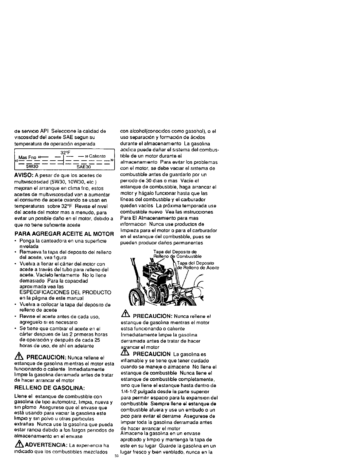
de serviclo API Selecclone la cahdad de
vlscosidad del acede SAE segun su
temperatura de operac=6n esperada
32_F
AVISO: Apesar de qua los aceltes de
multiviscos=dad (5W30, 10W30, etc )
mejoran el arranque en china fr_o, estos
acertes de mult_wscos=dad van a aumentar
el consumo de acelte cuando se usan en
temperaturas sobre 32°F Rewse el ravel
de] acerte del motor mas a menudo, para
evitar un poslble da_o en el motor, dab=do a
qua no tlene soficlente ace=re
PARA AGREGAR ACEITE AL MOTOR
• Ponga la canteadora en una superf[cle
ntvelada
•Remueva la tapa de] deposlto del relleno
del ace=te, yea figura
•Vuelva a Ilenar el c&rter del motor con
aerate a troves del tubo para relleno del
aceqte. Vaclelo lentamente No Io Ilene
demasiado Para la capac=dad
aproximada vea los
ESPECIFICACIONES DEL PRODUCTO
en la pz_g_nade este manual
•Vuelva a coJlocar la tapa del depOslto de
relleno de ace=re
•Rev=se el acerte antes de cada uso,
agreguelo s_ es necesarlo
•Se t_ene que camblar el acerte en el
c&rter despues de los 2pnmeras horas
de operac=6n ydespu6s de coda 25
horas de uso. de ah[ en adelante
A
LL_ PRECAUCION: Nunca rellene el
estanque de gasohna m_entras el motor esta
funcJonando o callente Inmsdtatamente
hmple la gasolma derramada antes de tratar
de hacer arrancar el motor
RELLENO DE GASOLINA:
Llene ei estanque de combustible con
gasohna de hpo automotrlz, Ilmpia, nueva y
sin plomo Asegurese que el envase que
est& usando para vac=ar la gasoSna este
5mp]o y sin polvo u otras partlculas
extraf_as Nunca use la gasohna qua pueda
astor rancla deb_do a los largos pertodos de
almacenam=ento en el envase
A_ ADVERTENCIA: La e:_per,encla ha
ind=cado que los combushbles mezclados 33
con alcohol(conocldos como gasohol), oel
uso separao6n y formacK_n de &c_dos
durante el almacenam_ento La gasohna
ac_d_ca puede da5ar el s_stema del combus-
hble de un motor durante el
almacenamlento Para evrtar los problemas
con el motor, se debe vac_ar el s_stema de
combustible antes de guardarlo pot un
pertodo de 30 dlas o mas Vacle el
estanque de combust=ble, haga arrancar el
motor y h&galo funclonar hasta que las
llneas del combustible y ei carburador
queden vaclos La pr6xlma temporada use
combustible nuevo Vea las mstrucc_ones
Para El Almacenam=ento para rues
informaoon Nunca use productos de
hmp=eza para el motor o para el carburador
en el estanque del combushble, pues se
pueden produc=r da5os permanentes
Tapa del Depos_to de
Relleno de Combusbble
PRECAUCION: Nunca rellene el
estanque de gaso]_na m=entras el motor
estsa funcionando oCallente
Inmed_atamente hmple la gasohna
derramada antes de tratar de hacer
,_ncar el motor
PRECAUCION La gasohna es
inflamable y se t=ene qua tarter cu=dado
cuando se maneje o almacene No Ilene el
estanque de combust=b[e Nunca liana el
estanque de combustible completamente,
smo que liana el estanque basra dentro de
1/4-1/2 pulgada desde la porte superior
para permd=r espac_o para la expansion del
combustible S_empre Ilene el estanque de
combust=ble afuera yuse un embudo o un
p=co para evltar el derrama Asegurese de
hmplar toda la gasohna derramada antes
de hacer arrancar el motor
Almacene Lagasolma en un envase
aprobado yI_mp_oy mantenga la tapa de
este en su lugar Guarde la gasohna en un
lugar fresco y b=en ventdado, nunca en la
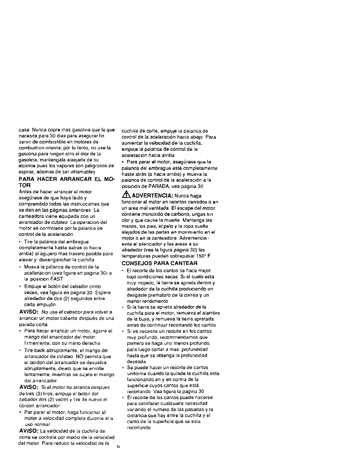
casaNunca copre mas gasohna que la que
necesJta para 30 d_as para asegurar fin
servlr de combusbble en motores de
combustion mtema, por Io tanto, no use la
gasohna para nmgun otro eEolor de la
gasohna, mantengala alaejada de su
a]cance pues los vapores son pehgrosos de
asptrar, ademas de ser _nflamabies
PARA HACER ARRANCAR EL MO-
TOR
Antes de hacer arrancar eJ motor
asegSrese de que haya leJdO y
comprend_do todas las instrucclones que
se dan enlas p&g_nas antertores La
canteadora vJene equrpada con un
arrancador de culateo La operacton del
motor es controlada por la palanca de
control de la ace_eractbn
• T_re la palanca del embrague
completamente hasta aatras (o hacta
arnba) el agujero mas trasero pos_ble para
elevar y desenganchar la cuchrlla
• Mueva la palanca de control de la
acelleraclon (yea figura en pagma 30) a
la posJc_on FAST
•Empul eel botbn de} cebador cmco
veces, yea figura en pagma 30 Espere
a]rededor de dos (2) segundos entre
cada empujbn
AVISO: No use el cel:)ador para volver a
arrancar un motor cal_ente despu_s de una
parada corta
• Para hacer arrancar un motor, agarre el
mango del arrancador del motor
flrmemente, con su mano derecha
• Tire back aloruptamente, el mango del
arrancador de cutateo NO permtta que
eJ cordon del arrancador se devuelva
abruptamente, delelo que se enroIJe
lentamente, mlentras se sujeta el mango
del arrancador
AMISO: St el motor no arranca despues
de Ires (3) bros. empule el boron def
cebador dos (2) veces y bre de nuevo et
cordon ar rancador
•Par parar el motor, haga f=JnClonar el
motor avelocJdad completa durame el U
uso normal
AVISO: La veloctdad de la cuchdla de
corte se controla por med_o de la veloodad
del motor Para reducer Ja velocfdad de ]a 34
cuchlla de corte, empuje la paJanca de
control de la aceleracJbn hacla abalo Para
aumentar la veloctdad de la cuchdla,
empule la palanca de control de la
acelerac_on hacta arr_ba
• Para parar el motor, aseg_rese que la
palanca del embrague est_ completamente
hasta alr&s (o hacra arnba) y mueva la
palanca de control de la acelerac_bn a la
pos=c=Sn de PARADA, vea pagma 30
/_ ADVERTENCIA: Nunca haga
tunc_onar el motor en recmtos corrados o en
un area real ventdada El escal::,_ del motor
contlene monoxldo de ¢arbono, ungas sm
olor yque cause la muerle Mantenga las
manos, los pies, eJ pelo y la ropa suelta
alejados de las partes en mowmtento en el
motor o en la canteadora Adventenoa -
eyrie el sLlenc_adory las areas a SU
alrededor (vea la figura pagma 30) las
temperaturas pueden sobrepasar 150 ° F
CONSEJOS PARA CANTEAR
•El recorte de los cantos se hace mejor
bajo condtclones secas Si el suelo esta
muy molado, la tlerra se apneta dentro y
alrededor de la cuchdia produc=endo un
desgaste prematuro de la correa yun
menor rendJm=ento
• Si la tlerra se apneta aJrededor de la
cuchJfla pare el motor, remueva el alambre
de Ja bulla, y remueva la tlerra apretada
antes de conhnuar recortando los cantos
• SI se neceslta un recorte en los cantos
muy profundo, recommendamos que
prlmero se haga uno menos profundo,
para luego corlar a mas profund_dad
hasta que se obtenga la profund=dad
deseada
• Se puede hater un rec,Ode de cantos
unlforme cuando la quiade la cuchdla esta
funclonando en yen contra de la
super[_cJe cuyos cantos que est&
recorlando Vea figura la pagtna 30
• El recorte de los cantos puede nacerse
para satlsfacer cua:qulera necesJdad
vartando el numero de las pasadas y la
d_stanoa que hay entre Tacuch_lla y el
canto de la superficte que se esta
reco_ando
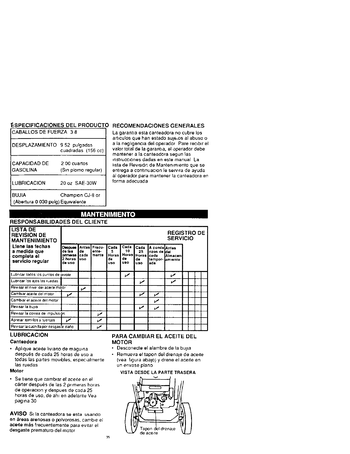
_SPEClFIOAClONES DEL PRODUCTO
CABALLOS DE FUERZA 3 8
DESPLAZAMIENTO 9 52 pulgadas
cuadradas (156 c(
CAPACIDAD DE 2 O0 cuartos
GASOLINA (Sin plomo regular)
LUBRICACION 20 oz SAE-30W
BUJIA Champion CJ-8 or
(Abertura 0 030 pulg) Equwalente
RECOMENDACIONES GENERALES
La garantla esta canteadora no cubre los
arhculos que han estado sule,os al abuso o
ala neghgencta del operadot Pare rectbtr el
valor total de la garantla, el operador debe
mantener a la canteadora segun las
mstrucclones dadas en este manual La
hsta de RevJslbr. de Mantemm_ento que se
enlrega a eontlnuac_on le serwra de ayuda
al operador para mantener la canteadora en
forma adecuada
RESPONSABILIDADES DEL CLIENTE
LISTA DE
'REVISION DE
IMANTENIMIENTO
Llane las fechas _pu= Ant=s Frecu- Cada Cada Cada A coral0 Antes
a medlda que _e las de ente- 5 10 25 nzos de del
completa el _r_ras cada mente Horas Hora_ Horas cada Almacen
Zhoras uso de do de tempor- ammnto
: servlclo regular :_euso uso uso uso ida
REGISTRO DE
SERVIClO
=dbr=car todos lOS punIos de 3=vote p_' Vt
_u Drtcar lOS eje_, la$ ruedas I/ P_
_evisar eRE'_'el Oel ,_celIe motor i/
.3amb_arace_tedelmoto_ _ _ p_
3amblar el ace,re del motor
i Rev,sar la bujta p_ _,f
Rewsa;la correade,mpulss,_n //'
iApre[ar tormllosytuercas _
/
Rev,sar la cucn,lla pot desgasle da_o
LUBRICAClON
Canteadora
•Aphque aeeJle hvlano de magu=na
despu_s de cada 25 horas de uso a
todas las partes movtbles, espec_almente
1as ruedas
Motor
•Se tlene que camblar el ace_te en el
carter despu_s de las 2 prtmeras horas
de operacTon y despues de cada 25
horas de uso, de aht en adelante Vea
pagma 30
AVISO St la canteadora se esta usando
en &reas arenosas o polvorosas, camb_e el
ace_te m_,s frecuentemente para evttar el
desgaste prematuro del motor
PARA CAMBIAR EL ACEITE DEL
MOTOR
•Desconecte el alambre de la bulta
• Remueva el tapon del drenaje de aceEte
(yea figura abajo) y drene el acette en
un envase piano
VISTA DESDE LA PARTE TRASERA
35
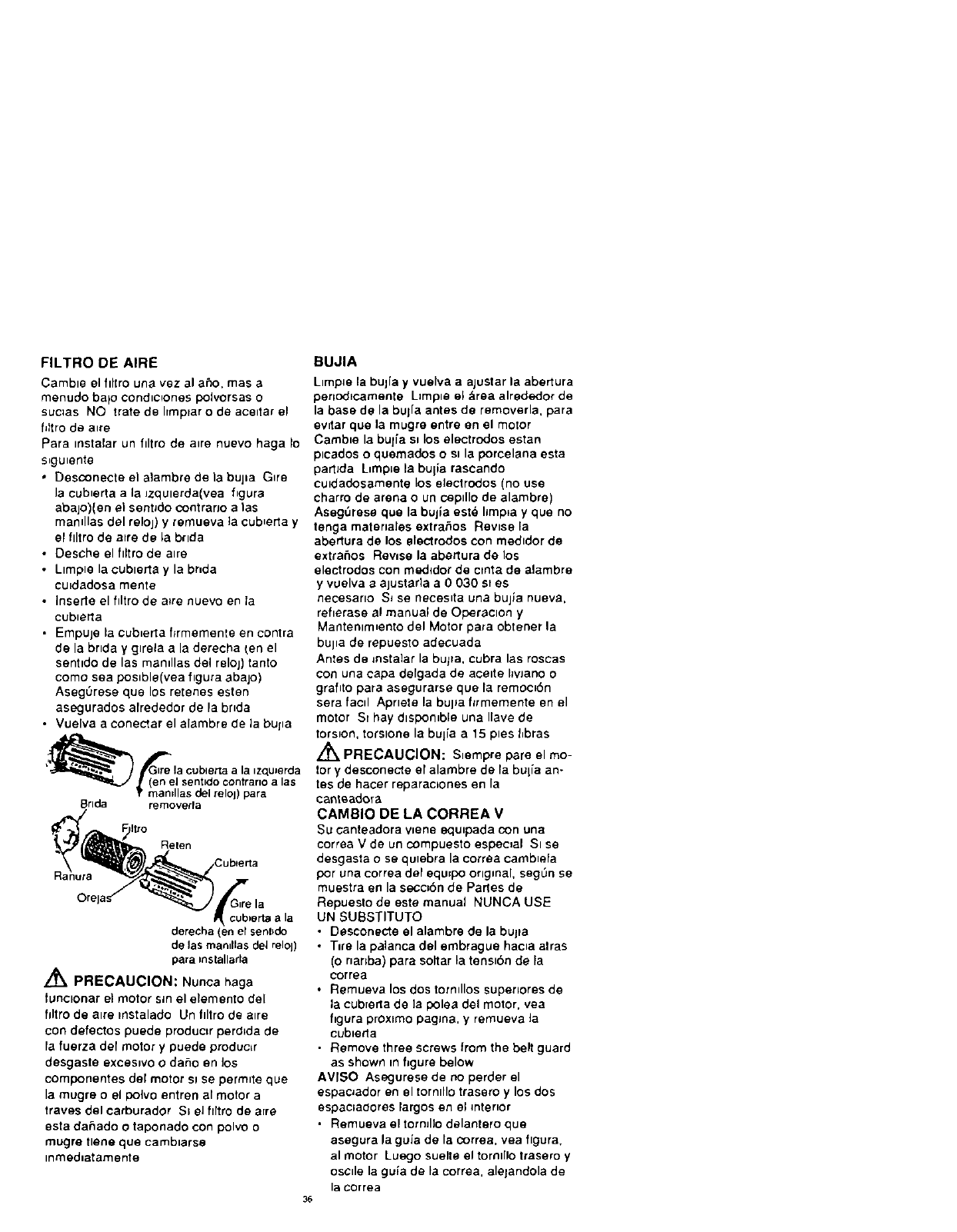
FILTRO DE AIRE
Camble el flltro una vez al aPJo, mas a
menudo balo cond_c=ones polvorsas o
suclas NO tratede hmprar o de aceltarel
filtro de a_re
Para instalar un filtro de a_re nuevo haga Io
s_gu_ente
•besconecte el a}ambre de la bupa G_re
Ja cub_erta ala Jzqulerda(vea figura
abajo)(en el sentJdo contrario alas
mamllas del reloj) y remueva la cub_erta y
el flltro de a=re de la br=da
•Oesche el filtro de alre
• Limple la oublerta y la bnda
cu_dadosa monte
•Inserte el filtro de atre nuevo en ta
cubleila
•Empuje la cub_erta flrmemente en contra
de la bnda yg=rela ala derecha Len el
sentldo de las mamllas del reloj) tanto
como sea poslble(vea figura abajo)
AsegOrese que los retenes esten
asegurados alrededor de la bride
•Vuelva a conectar el alambre de ]a bupa
8rlda removerra
Reten
R
cubierta ala
derecha (en el sent_do
de las man_llasdel relol)
para mstallarla
/_ PRECAUCION: Nunca haga
tunclonar el motor sin el elemento de[
hltro de alre mstalado Un filtro de alre
con defectos puede produc=r perdlda de
fa fuerza de[ motor y puede produc{r
desgaste exces_vo o daho en los
componentes del motor slse permute que
la mugre o el polvo entren al motor a
traves del oarburador SI eJ flltro de a[re
esta daeado o taponado con polvo o
mugro tlene que camb_arse
inmed=atamente
BUJIA
L_mp_e la bulia y vuelva a ajustar la abertura
penodlcamente L=mple el &rea alrededor de
la base de la buj[a antes de removerla, para
evltar que la mugre entre en el motor
Cambie la but{a ei los electrodos estan
plcados o quemados o st la porcelana esta
partlda Limp[e la buiia rascando
euidadosamente los electrodos (no use
oharro de arena o un cepdlo de alambre)
Aseg_rese que la bujla est@ hmpla y que no
tenga mater=ales extrahos Revise la
abertura de los electrodos con medldor de
extrahos Rewse la abertura do los
electrodos con medldor de clnta de alambre
yvuelva eajustarla a 0030 st es
necesarlo S_ se neces_ta una bujla nueva,
reflerase 81 manual de Operaolon y
Mantenlm_ento del Motor para obtener la
bujla de repuesto adecuada
Antes de mstalar la bu/ra, cubra las roscas
con una cape defgada de acelte hvJano o
grafito para asegurarse que la remoe_en
sere facd Aprlete la bulJa ftrmemente en el
motor SI hay dlspomble una Ilave de
torsion, torslone la bulia a15 pies t_bras
L_ PRECAUCION: Slempre pare el mo-
tor y desconecte el alambre de la bulia an-
tes de hacer reparac=ones en la
canteadora
CAMBIO DE LA CORREA V
Su canteadora wene equ_pada con one
correa V de un compuesto especial SIse
desgasta ose qulebra la correa oamb_efa
por una correa del equ_po original, segL_n se
muestra en la secc=6n de Parles de
Repuesto de este manual NUNCA USE
UN SUBSTITUTO
• Desconecte el alambre de la bulge
• T=re la palanca del embrague hac_a aires
(o nanba) pare soltar la tens=bn de la
COFFee
•Remueva los dos tormllos superlores de
la cub[erta de la polea del motor, yea
figure proximo pagma, y remueva ]a
cub_er_a
• Remove three screws from the belt guard
as shown in figure below
AVISO Asegurese de no perder el
espaoador en el tornlllo trasero y los dos
espaeladores largos en el interior
• Remueva el tormllo delantero que
asegura la guia de la correa, yea flgura,
al motor Luego suelte el tornl[IO trasero y
oscde la guia de la correa, aletandola de
la correa
36
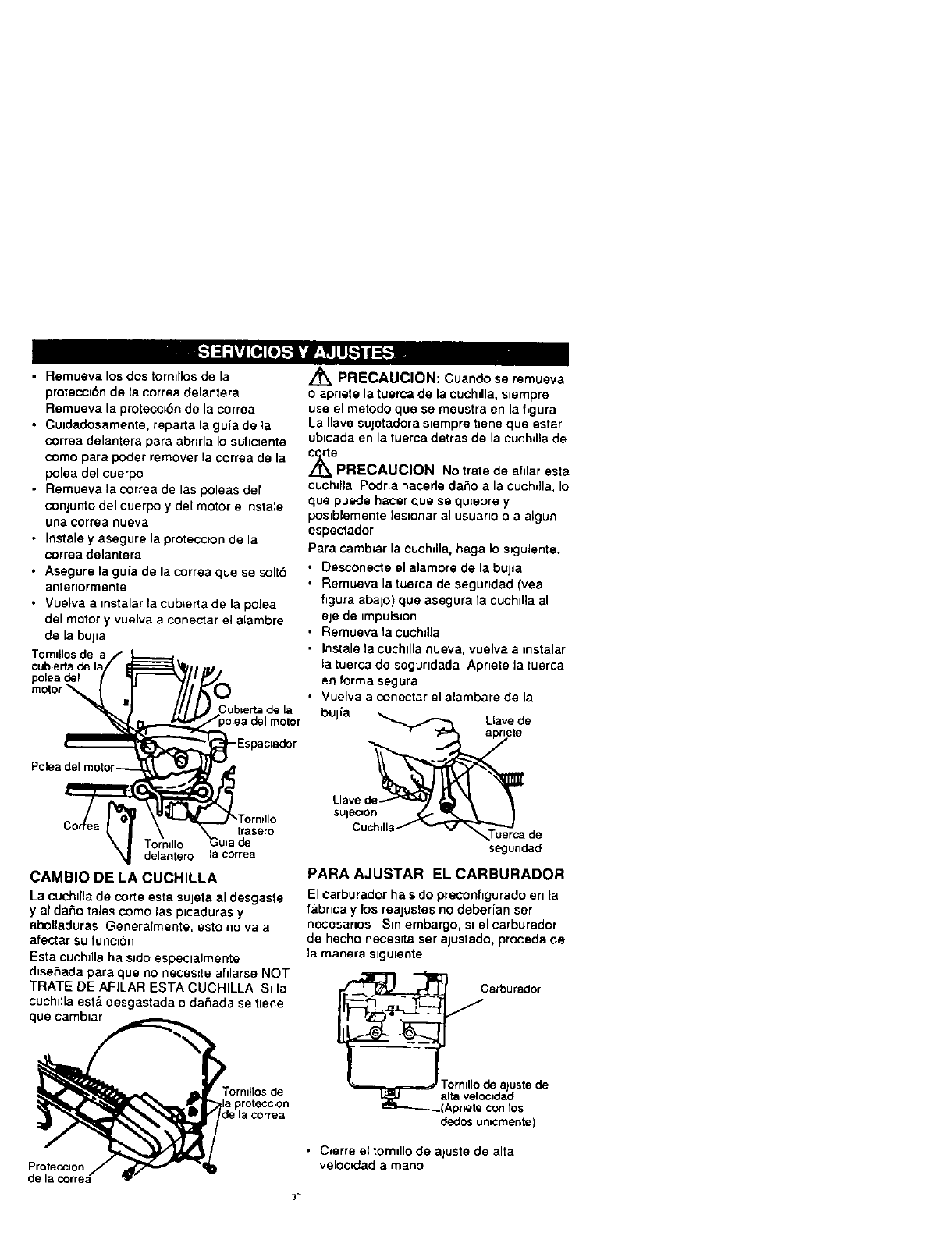
•Remueva los dos torntllos de la
proteccibn de la correa delantera
Remueva la protecobn de la eorrea
•Cuidadosamente, reparta la gula de la
correa delantera pare abnrla Io sufictente
como para poder remover la correa de la
polea de1 euerpo
• Remueva la correa de las poleas del
conjunto del euerpo y del motor emstale
una correa nueva
• Instale y asegure la proteccton de la
correa delantera
• Asegure la gufa de la correa que se soltb
antenormente
• Vuelva a mstalar la cubLerta de la polea
del motor y vuelva a conectar el alambre
de la bujla
Tomdlos de la
polea del
motor Cub=erta de La
-Espac=ador
trasero
de
delantero la ¢orrea
CAMBIO DE LA CUCHILLA
La cuchtlla de corte esta sujeta al desgaste
y af da_o tales como las p=caduras y
abolladuras Generalmente, esto no vaa
afectar eu funcL_n
Esta cuchdla ha sido espeetalmente
dtsehada pare que no neces=te afilarse NOT
TRATE DE AFILAR ESTA CUCHILLA St le
cuchdla est& desgastada o daSada se ttene
qua camb=ar
,_ PRECAUCION: Cuando se remueva
o aprtete la tuerca de la cuchdla, stempre
use el metodo que se meustra en la hgura
La Ilave euletadora s_ernpre _ene que ester
ubtcada en la tuerca detras de la cuchdla de
,_epRECAUCION No trate de ahlar esta
cuchllla Podna hacerle daSo ala euchdla, Io
que puede hater que se qu=ebre y
pOslblemente les_onar al usuerlO o a algun
espectador
Para camblar la cuchdla, haga Io spgulente.
• Desconecte el alambre de la bujla
• Remueva la tuerca de segundad (yea
figura abalo) que asegura la cuchdia al
eje de _mpuls=on
• Remueva la cuchdLa
• Instale la cuchtlla nueva, vuelva a msta,lar
la tuerca de segurldada Apnete la tuerea
en forma segura
• Vuelva a conectar ol alambare de la
bujla _ Llave de
Llavede_ _I_ '_ 1
'°'c:: °o
segundad
PARA AJUSTAR EL CARBURADOR
El carburador ha sldo precon_tgurado en la
fabrtca y los reajustes no deber[an ser
necesanos Sm embargo, Sl el carburador
de hecho necesita ser alustado, proceda de
la manera stgu_ente
Csrburador
/
T_'-_'_-'-'_- rorntllo de aluste de
dedos umcmente)
• C=erre el tomdlo de aluste de alta
veloctdad a mano
Proteoclon
de la correa
3-
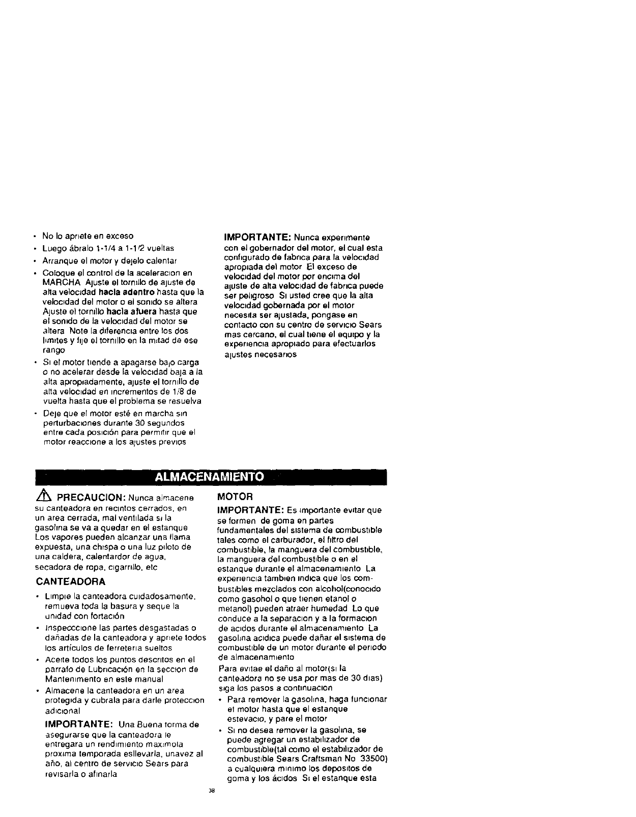
•No Io aprtete en exceso
• Luego &bralo 1-1/4 a 1-1/2 vueltas
• Arranque el motor y dejelo calentar
•Coloque el control de la aceleracnon en
MARCHA Ajuste el tormJJo de ajuste de
alta veloc]dad hacla adentro haste que la
veloc_dad del motor o el somdo se aftera
Ajuste el tornJI)O hacla afuera haste que
el sonido de la veloctdad del motor se
altera Note la dJferencla entre los dos
hmrtes y ftje e] torntllo en la m_tad de ese
tango
•Si el motor ttende a apagarse bajo carga
ono acelerar desde _a velocidad baJa ala
alta aprop_adamente, ajuste el tormllo de
aEta veloetdad en tncrementos de 1,,'8de
vuerta hasta que el problema ee resuelva
• Deje que el motor est_ en marcha stn
perturbaenones durante 30 segundos
entre cada position para permntnr que el
motor reacclone alos ajustes prevlOS
IMPORTANTE: Nunca experlmente
con eJ gobernador del motor, el cual esta
configurado de fabnca pare la velocadad
aprop=ada del motor F:I exceso de
veloctdad del motor por encama del
aluste de alta veloctdad de fabrtca puede
ser pehgroso Sl usted cree que la aJta
veloc=dad gobernada por el motor
neces=ta ser ajustada, pongase en
contacto con su centro de servtc_o Sears
rues eercano, el cual t=ene el equ=po yla
exper=encla aproplado para efectuarlos
alustes necesaruos
PRECAUCION: Nunca almacene
su canteadora en reclntos cerrados en
un area cerrada, real ventllada sJ la
gasohna se va a quedar en el estanque
Los vapores pueden alcanzar una llama
expuesta, una chrspa o una luz pdoto de
una caldera, calentardor de ague
secadora de rope, clgarntJo, etc
CANTEADORA
• Ltmpte la canteadora cutdadosamente.
remueva toda la basura y sequela
dmdad con fortacp6n
• Inspeccctone las partes desgastadas o
dahadas de la canteadora y aprJete todos
los art_culos de ferreterla sueltos
• Acerte todos los puntos descrttos en el
oarrafo de Lubncac=bn en la seccuon de
Mantemmento en este manual
• Almacene la canteadora en un area
oroteg_da ycubrala pare darle protecc_on
adnctonal
IMPORTANTE: Una Buena rorma de
a_egurarse que la camea_ora le
entregara un rendlmlento maxtmola
proxJma temporada esllevarla, unavez al
a_o, al centro de serwcno Sears Dare
revtsarla o aftnarla
MOTOR
IMPORTANTE: Es _mportante evJtar que
se formen de goma en partes
fundamentales del ststema de combustFble
tales como el carburador, el fittro del
combusttble, la manguera del combusbble,
la manguera del combustnble o en el
estanque durante el almacenamlento La
exper=encua tamb_en ind=ca que los com-
bustibles mezdados con alcohol(conoctdo
como gasohol o que t=enen etanol o
metanol) pueden atraer humedad Lo que
conduce ala separac=on yala formac=on
de acndos durante el almacenamlento La
gasohna aeldlca puede daSar el s_stema de
combustible de un motor durante el perlodo
de almacenam=ento
Pare ewtae el dane al motor(el la
canteadora no se usa pot mas de 30 dtas)
sJga los pasos e contmuaclon
• Pare remover la gasohna, haga funelonar
et motor hasta que el estanque
estevacJo, y pare el motor
• SI no deeea remover la gasohna, se
puede agregar un estabthzador de
combustlb)e(tal como el estabtllzador de
combustnbJe Sears Craftsman No 33500)
a cualqulera mnnlmo los deposntos de
goma y los actdos S= el estanque esta
38
asl vacio, mezcle el estabdlzador con
gasohna nuevan en un envase aparte y
agregue algo de _sto al estanque
Slempre siga 1as ir_strucciones en el
envase del establllzador Luego, haga
funcionar e] motor per Io menos per 10
minutes despues de que se haya
agregado el estabd_zador para perm,t,r
que la mezcla alcance al ¢arburador
Guarde la canteadora en un lugar
seguro Yea la advertencla anterior
• Almaoene la canteadora en la pospc_on
de operac_bn con ras ruedas abalo S_ se
guarda la oanteadora en cualqu_era otra
poslcl6n, e_ acelte del c_rter puede
entrar en el cihndro, produc_endo un
problema que neceslte serwc=o
Puede mantener su motor en buenas
conchc=ones de operac[on durante el
almacenam]ento af
•Camb[ar el acelte
•Lubncar el &rea del plston/cllmdro Esto
se puede hacer remowendo _a bulfa
pnmero y roclando acelte de motor hmplo
en el agujero de la bujla =uego c6bralo
con un trapo para abosrber el roc{o del
ace_te Luego. rote el motor t_rando el
arrancador dos o tres veces Finalmente,
vuelva a mstalar la bul[a adjunte el
alambre de esta
IIa]=_i i [_l_r[_] _o_:_ r_ 1
PROBLEMA
Arranque dlflcll
El motor funclona
err_tlcamente
CAUSA
Combust*b]e ranclo
Bu}[a defectuosa
FiItro del combustible taponado
Llnea del combust_bIe bloqueada o
estanque de comeust_ble vacto
Carburador desajustado
Buj[a mala
FiItro de alre taponado
CORRECCION
Orene el estanque de combustible
Ll_nelo con comb_Jstlble nuevo
L_mple y vuelva a ajustar la
abertura de la bupa
Camb_e el filtro de combustible
LimpJe la hnea del combustible
rewse el estanque de gasohna
Ajuste el carburador
Llmple yalusle la abertura
bmpLelo goipeandolo o¢amble el
filtro de alre
Despele la obstruccron
Apr)ete la tuerca de retenc_on de
la cuchdla
Camb_e la correa V
Gamble los rodam_entos
Ata,scamlemo debJdo a objetos
La cuchllla de extra_os
corte no glra Cuchdla suelta
Correa Vclefectuosa
RodamJentos del cuerpo defectuoso
La cuchllla no
corta en forma Cuchrlla clar_ada o desgastacla Camb=e cuchdla
adecuada
Vibraci6n Pare el motor inmed_atamente
exceslva Partes sueltas apr_ete redes los pernos S_
continua fa wbracaclon Ileve la
unldaCI al Centre de Serwc_o Sears
39

For the repair or replacement parts you
need delivered directly to your home
Call 7am-7 pm, 7 days a week
1-800-366-PART
(1-800-366-7278)
Para ordenar piezas con entrega
a domicilio -1-800-659-7084
For in-house major brand repair service
Call 24 hours a day, 7 days a week
1-800-4-REPAIR
(1-800-473-7247)
Para pedir servicio de reparacion a
domicilio -1-800-676-5811
For the location of a Sears Parts and
Repair Center in your area
Call 24 hours a day, 7 days a week
1-800-488-1222
For information on purchasing a Sears
Maintenance Agreement or to inquire
about an existing Agreement
Call 9 am -5pro, Monday-Saturday
1-800-827-6655
When requesting service or ordering
parts, always provide the following
information:
Product Type Part Number
• Model Number Part Description
,_,'n,_r_ca'5Repa,rSpec_alJsls Prmtad =n U S A
