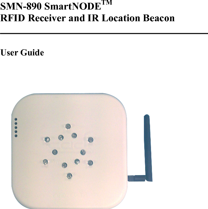
Cadi Scientific SMN890 SMART NODE RECEIVER 890 User Manual SMN 890 SmartNODE User Guide

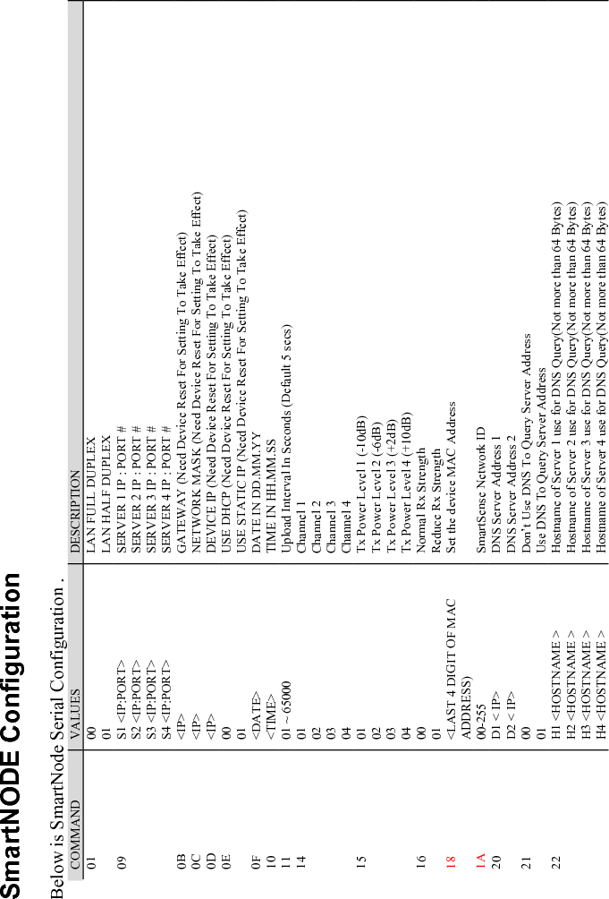
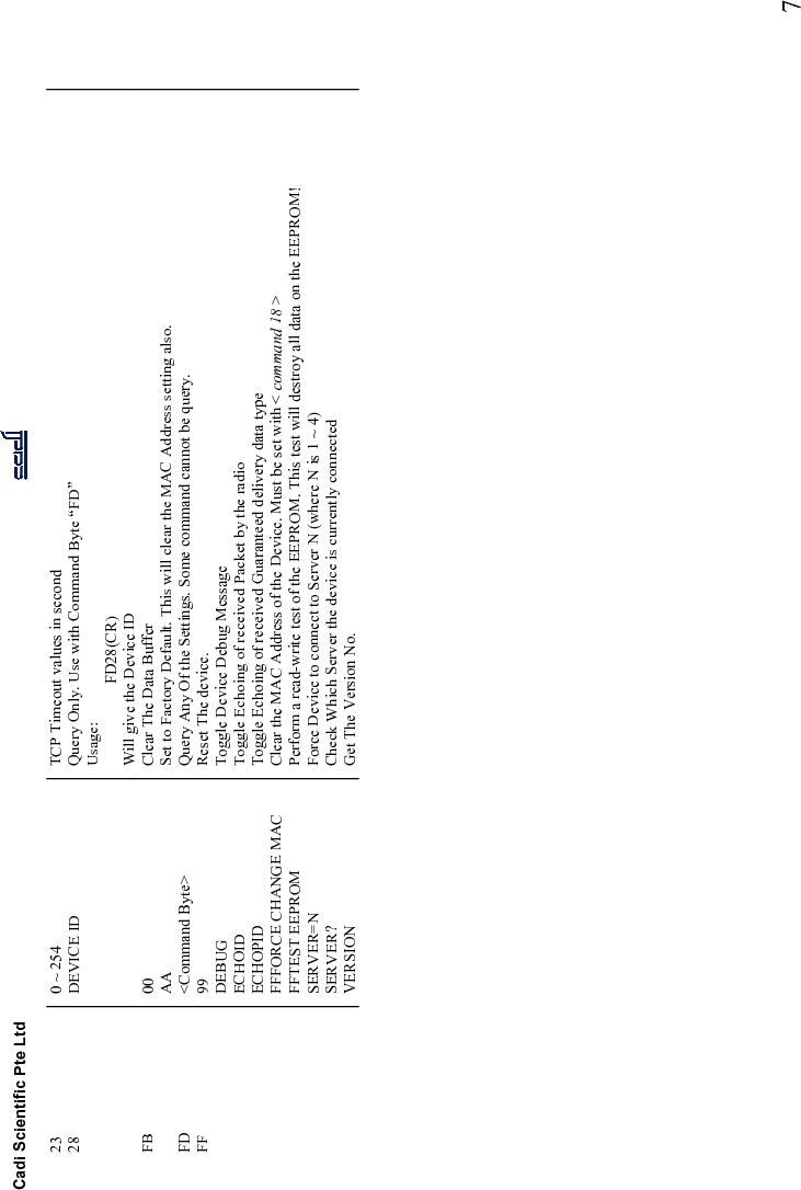
Cadi Scientific Pte. Ltd. SMART NODE RECEIVER 890 SMN 890 SmartNODE User Guide

user manual

      SM-890 SmartODETM RFID Receiver and IR Location Beacon   User Guide
Cadi Scientific Pte Ltd      2
Cadi Scientific Pte Ltd      3    Federal Communications Commission (FCC) Statement  15.21 You  are  cautioned  that  changes  or  modifications  not  expressly  approved  by  the  part responsible for compliance could void the user’s authority to operate the equipment.  15.105(b) This  equipment  has  been  tested  and  found  to  comply  with  the  limits  for  a  Class  B  digital device, pursuant to part 15 of the FCC rules. These limits are designed to provide reasonable protection against harmful interference in a residential installation. This equipment generates, uses and can radiate radio frequency energy and, if not installed and used in accordance with the instructions, may cause harmful interference to radio communications. However, there is no guarantee that interference will not occur in a particular installation. If this equipment does cause  harmful  interference  to  radio  or  television  reception,  which  can  be  determined  by turning the equipment off and on, the user is encouraged to try to correct the interference by one or more of the following measures:  -Reorient or relocate the receiving antenna. -Increase the separation between the equipment and receiver. -Connect the equipment into an outlet on a circuit different from that to which the receiver is connected. -Consult the dealer or an experienced radio/TV technician for help.  Operation is subject to the following two conditions: 1) this device may not cause interference and 2) this device must accept any interference, including interference that may cause undesired operation of the device.     COPYRIGHT  Specifications are subject to change without notice.  Copyright © 2003 Cadi Scientific Pte Ltd.  All rights reserved.   Cadi Scientific Pte Ltd 31, UBI ROAD 1 #03-00 AZTECH BUILDING Singapore 408694 Singapore http://www.cadi.com.sg
Cadi Scientific Pte Ltd      4    Introduction   The  SMN-890  SmartNODETM  RFID  Receiver  is  an  integral  component  of  the SmartSense  Wireless  Vital  Signs  and  Location  Tracking  System.  The  system  is designed for  wireless and  automated  measurement and  recording of patient vital signs and for location tracking of patients and high-value assets.   The  SMN-890  will  periodically  transmit  IR  and  LF  beacon  signal.  This  beacon signal consists of unique location ID. This location will be received by tag which are  in  range.  IR  and  LF  signal  are  very  localized  which  give  better  location tracking determination.  The  SMN-890  SmartNODETM  RFID  Receiver  is  a  LAN-enabled  receiver  for receiving  data  transmitted  by  the  SmartSenseTM  series  of  wireless  sensors  and monitors.    The  receiver  uploads  data  received  from  the  sensors  to  the SmartSenseTM database via its built in Ethernet LAN interface.  In a typical installation, the receivers are to be installed at strategic locations in the hospital in a manner to meet the specific coverage requirement of the application.  The  receivers  being  Ethernet  LAN  capable  lend  themselves  well  to  deployment using standard Ethernet LAN equipment and infrastructure.
Cadi Scientific Pte Ltd      5     Typical System Setup  The  following  diagram  shows  how  SMN-800/900  is  deployed  in  a  typical SmartSense System configuration.          etwork Switch AC Outlet Server Power Ethernet Ethernet
SmartNODE Configuration  Below is SmartNode Serial Configuration . COMMAND  VALUES  DESCRIPTION 01  00 01 LAN FULL DUPLEX LAN HALF DUPLEX 09  S1 <IP:PORT> S2 <IP:PORT> S3 <IP:PORT> S4 <IP:PORT> SERVER 1 IP : PORT # SERVER 2 IP : PORT # SERVER 3 IP : PORT # SERVER 4 IP : PORT # 0B  <IP>  GATEWAY (Need Device Reset For Setting To Take Effect) 0C  <IP>  NETWORK MASK (Need Device Reset For Setting To Take Effect) 0D  <IP>  DEVICE IP (Need Device Reset For Setting To Take Effect) 0E  00 01 USE DHCP (Need Device Reset For Setting To Take Effect) USE STATIC IP (Need Device Reset For Setting To Take Effect) 0F  <DATE>  DATE IN DD.MM.YY 10  <TIME>  TIME IN HH.MM.SS 11  01 ~ 65000  Upload Interval In Seconds (Default 5 secs) 14  01 02 03 04 Channel 1 Channel 2 Channel 3 Channel 4 15  01 02 03 04 Tx Power Level 1 (-10dB) Tx Power Level 2 (-6dB) Tx Power Level 3 (+2dB) Tx Power Level 4 (+10dB) 16  00 01 Normal Rx Strength Reduce Rx Strength 18  <LAST 4 DIGIT OF MAC ADDRESS) Set the device MAC Address 1A  00-255  SmartSense Network ID 20  D1 < IP> D2 < IP> DNS Server Address 1 DNS Server Address 2 21  00 01 Don’t Use DNS To Query Server Address Use DNS To Query Server Address 22  H1 <HOSTNAME > H2 <HOSTNAME > H3 <HOSTNAME > H4 <HOSTNAME > Hostname of Server 1 use for DNS Query(Not more than 64 Bytes) Hostname of Server 2 use for DNS Query(Not more than 64 Bytes) Hostname of Server 3 use for DNS Query(Not more than 64 Bytes) Hostname of Server 4 use for DNS Query(Not more than 64 Bytes)
Cadi Scientific Pte Ltd     7 23  0 ~ 254  TCP Timeout values in second 28  DEVICE ID  Query Only. Use with Command Byte “FD” Usage:   FD28(CR) Will give the Device ID FB  00 AA Clear The Data Buffer Set to Factory Default. This will clear the MAC Address setting also. FD  <Command Byte>  Query Any Of the Settings. Some command cannot be query. FF  99 DEBUG ECHOID ECHOPID FFFORCE CHANGE MAC FFTEST EEPROM SERVER=N SERVER? VERSION Reset The device. Toggle Device Debug Message Toggle Echoing of received Packet by the radio Toggle Echoing of received Guaranteed delivery data type Clear the MAC Address of the Device. Must be set with < command 18 > Perform a read-write test of the EEPROM. This test will destroy all data on the EEPROM! Force Device to connect to Server N (where N is 1 ~ 4) Check Which Server the device is currently connected Get The Version No.
   Specifications   TECHICAL DATA   Interfaces   Ethernet LAN  10 Base-T    RF     RF Frequency  US (SMN-9xx):         919.8MHz or 925MHz Europe (SMN-8xx):   868.4MHz   Input connector  US (SMN-9xx):         RP-SMA Europe (SMN-8xx):   SMA   Input impedance  50ohm    IR    Frequency  38kHz Nature  940 nm peak IR wavelength    LF    Frequency  125Khz Nature   Magnetic Field Signal Power     Power source  12VDC    Current consumption  250mA     Environment     Operating temperature range  10 oC  – 50oC Storage & Transport temperature range -15 oC -  60 oC Physical     Dimension  140 x 140 x 35mm   Weight  300g    Compliance     Certification  CE, FCC   RF Compliance  ETSI EN 300 220   EMC Compliance  ETSI EN 301 489
Cadi Scientific Pte Ltd      9

Navigation menu