Cadwell CADWELL-1 Wireless EEG Recorder User Manual Easy III Operators Manual
Cadwell Wireless EEG Recorder Easy III Operators Manual
Cadwell >
Contents
- 1. User Manual Excerpt
- 2. First half User Manual
- 3. Second half User Manual
First half User Manual

1
CADWELL EASY® III
OPERATOR’S MANUAL
PART NUMBER 100840-620
REV 3.5.1 - AUGUST - 2009
909 North Kellogg Avenue Kennewick, Washington 99336
800.245.3001 509.735.6481 509.783.6503 Fax
www.cadwell.com info@cadwell.com international@cadwell.com

Cadwell Easy III – Version 3.5
2
COPYRIGHT
© 2009 Cadwell. All rights reserved.
No part of this publication may be reproduced, transmitted, transcribed, stored in a retrieval system,
translated into any language or computer language, in any form, by any means, electronic,
mechanical, optical, chemical, manual, or otherwise without prior written consent of Cadwell.
Disclaimer
Clinical conclusions and decisions based on the use of this product are the responsibility of the user.
Cadwell does not accept any liability or responsibility for damages arising out of the use of or inability
to use this product.
This document may contain technical inaccuracies or typographical errors. Changes are periodically
made to the information herein; these changes will be incorporated in future revisions of this
document. Features and specifications are subject to change without notice.
Cadwell does not accept any liability for the use or misuse, direct or indirect, of this product. Users
must accept all responsibility for any results obtained by or concluded from data obtained by the
products. The user must accept all responsibility for results obtained by software from Cadwell
Laboratories, Inc.
Trademark Notices
Cadwell, Easy, EasyNet, and Q-Video are registered trademarks of Cadwell, Inc. This document also
contains trademarks of other companies.

3
EASY III DATA ACQUISITION SYSTEM
The Cadwell Easy III is an advanced data acquisition system for recording brain wave and other
physiological signals. Easy III provides control, display, event notation, storage and reporting on
acquired data.
The Easy III's software supports multiple amplifier platforms available from Cadwell. Data
management includes viewing or reading EEG data on a reader computer, saving and recalling
some or all of the record for future reference, and being able to easily find records among the
hundreds generated by each system each year.
Easy III is designed to facilitate report generation for both the individual patient and for the
clinic.
Intended Use
The Easy III system is intended for the acquisition of EEG and other polygraphic channels. The
Easy III system is intended for use by a physician or a trained technician under the supervision of
a physician. The Easy III intended recording environment is in a hospital, clinic, physician’s
office, or other appropriate testing environments.
Operator's Manual Intended Use
This manual provides an operational summary of the Easy III Data Acquisition System.
This manual does not provide clinical training. It is assumed that the user has adequate clinical
training to perform procedures involving the Easy III.
Please refer to the following sources for more information on the Easy III.
Cadwell Easy III Help File. Available with installed Easy III application and at
www.cadwell.com
Cadwell Easy III Technical Manual.
www.cadwell.com
Cadwell Customer Support.
Cadwell Easy III – Version 3.5
4
New Features and Enhancements in Easy III, Version 3.5
General Features
1. Record Optimizations have been added to reduce overall file size.
Compression is dynamically applied as data is saved. A new option
has also been added that allows the user to eliminate unused inputs
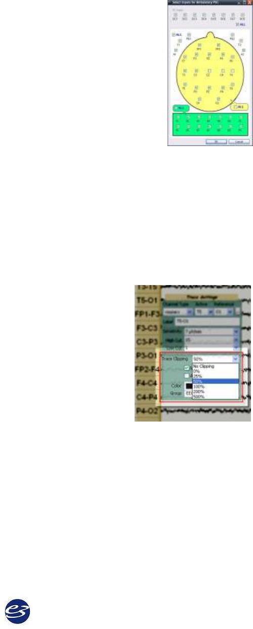
before data is collected. Note page 153.
2. Paging Speed Enhancements (with and without video) have been
added to increase paging speed during review. Users will see
improvement when paging through studies that are on the local or
remote/network drives.
3. End users have requested that new windows added through the
‘Show Window’ option be displayed at all times (this now applies to
all windows added such as Q-Video, additional trace windows, etc.).
4. The Easy III Office Server can now be configured as a Service, eliminating the requirement to
leave the Office Server system logged in at all times. Note page 65.
5. The Report Generator will now import Word templates.
6. Implemented new software for the KWorld video to USB adapter to optimize performance
with Q-Video.
7. Record Opening time has been improved for remote records. Some marginal improvements
are also seen with local records.
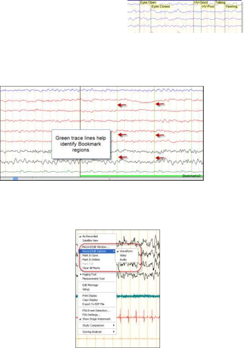
8. Trace Band Clipping Feature. This new option will allow the
user to configure how much overlap is allowed between
recorded channels. Settings can be accessed through the
montage editor or by left clicking on the trace labels during
review or data collection. Trace band overlap settings can also
be adjusted ‘on-the-fly’ by left clicking on the trace label
during data collection or review. Note Page 101.
9. Implemented additional changes to improve Easy III time
synchronization (when comparing Easy III real time
calculation to operating system time setting).
10. Changes have been made to the measurement tool to make sure the tool works consistently.
11. When paging, the page with ‘focus’ will page at the displayed page duration. For example,
if you are looking at data in a 1 second page, the paging tool will advance by 1 second pages.
12. Linked channel EEG settings, montage name, and notch filter status have been added to the
top of waveform printouts.
13. Implemented new performance monitoring output tool. This tool is available in the Tools
menu. Selecting this option will place several performance metrics in the Windows clip
board. Select paste to copy the contents into MS Word.
5
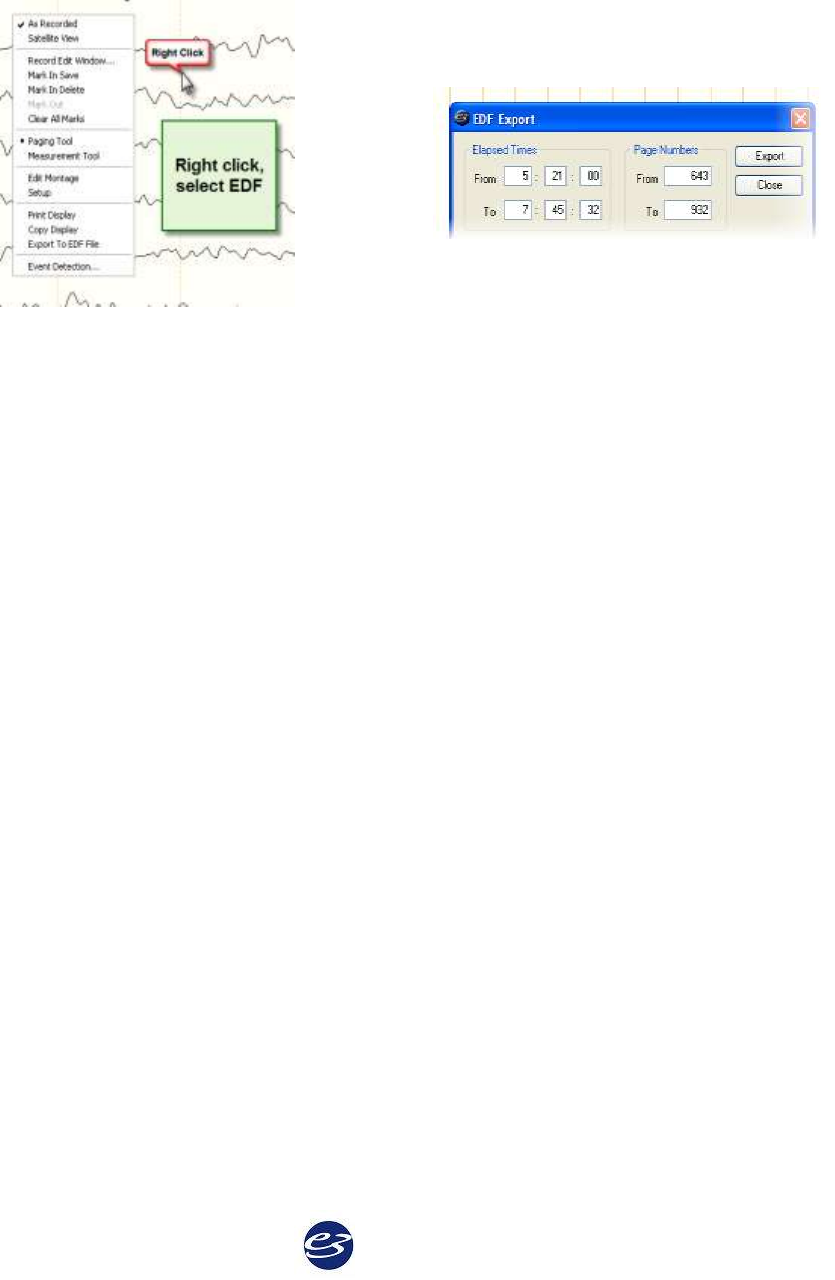
14. Default Bookmark durations have been added based on user feedback.
15. Event text placement has been improved. Text
will entries will be displayed adjacent to each
other. The event line helps the user quickly
associate the event text/event location.
16. Comment text placement in the trace window has been modified based on user feedback.
17. Real time values have been added to the bookmark list. The comment column has also been
expanded to display more characters.
18. Added bookmark-specific grid line colors to the trace window.
19. New Impedance Default Setting. Impedance LEDs on amp now default to 5K when
launching impedance from software.
20. Trace Window Record Editing has been changed to allow the user to specify the type of data
(waveform, video or audio) to be edited when right clicking in the trace window. The
selected data types for editing are saved with the users Easy login name.
Cadwell Easy III – Version 3.5
6
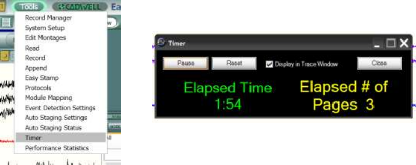
21. EDF file export has been added. Right click in the trace window to access the EDF export
tool. Montage changes will no longer break the EDF file extraction.
22. New Hot Keys – The following hot keys have been added.
F2 - Event List
F3 - Q-Video Player in review window only
F4 - Default Report 1 (R1)
F5 - Default Report 2 (R2)
F6 - Default Report 3 (R3)
The following keyboard hot keys require the mouse to be placed over the trace window.
CTRL B - Go forward to next bookmark
CTRL G - Go to page number tool will appear
CTRL ↑- Decrease displayed paper speed of trace window with mouse focus
CTRL ↓ - Increase displayed paper speed of trace window with mouse focus
CTRL M - Display montage list
CTRL + Auto page forward (press CTRL + again to increase paging speed, CTRL to decrease
paging speed)
CTRL - Auto page backward (press CTRL + again to increase paging speed, CTRL to
decrease paging speed)
CTRL A - Change displayed montage with mouse focus back to ‘as recorded’
CTRL 1- 9 - Change the displayed montage to the default montage specified for M1-M9
CTRL P - Reposition to start of photic stimulation (EEG)
CTRL H- Reposition to start of hyperventilation (EEG)
CTRL L - Reposition to Lights Out (PSG)
CTRL S - Reposition to Sleep Onset (PSG)
7
CTRL R - Reposition to REM Onset (PSG)
CTRL C - Advance to next CPAP/Bilevel pressure (PSG)
Home Key – Reposition to Start of Recording
End Key – Reposition to End of Recording
Space Bar – Advance forward one page
Pg Up – Advance backward one page
Pg Dn – Advance forward one page
↑- Increase linked sensitivity
↓- Decrease linked sensitivity
→ Page forward
← Page backward
EEG, LTM, and ICU Specific Features
1. Recording Timer. The Timer can be used to keep track of elapsed time and pages. Events
will be added to the trace window every 10 seconds. The user can select an option to not
write the events to the trace window if required.
2. Added the option to allow users to delete Persyst spike events from Easy Event list.
Cadwell Easy III – Version 3.5
8
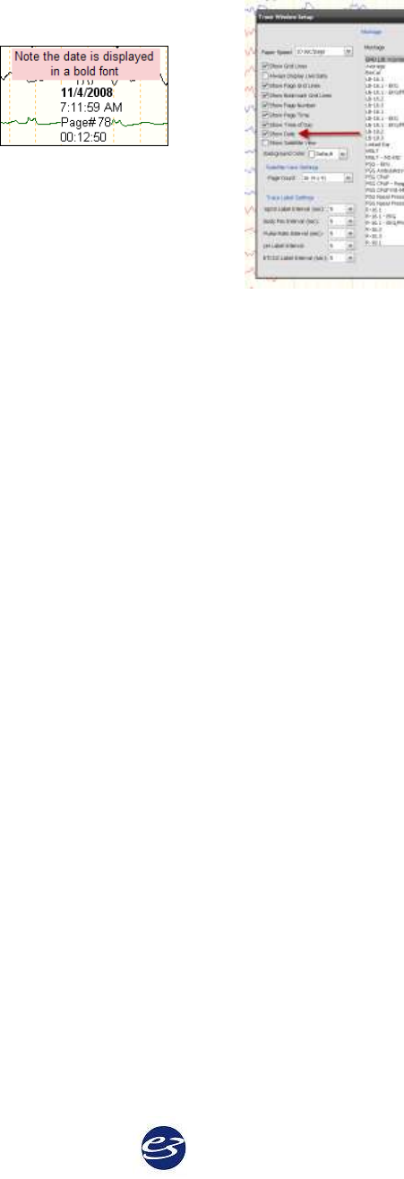
3. The recording date is now displayed in the trace window. Right click in the trace window,
select setup to add the date to the trace window.
4. The impedance button has been put in the EEG review menu based on user feedback.
5. More EEG montage buttons have been added to the review menu based on user feedback.
6. Easy III Photic Stimulator improvements for EEG customers. Fixed some issues whereby the
Photic stimulator tick marks and accompanying frequency text were not always displayed
correctly.
7. Implemented Patient Event Marker detection. Events are displayed in the event list and
position bar now. The new patient event button plugs into an Easy III or Easy II DC input.
8. Remote Viewing of Magic Marker. Remote viewing of Magic Marker data through Easy III
has been added.
PSG Features
1. New Chronological CPAP table for PSG customers (lists pressures chronologically, duplicate
pressures on separate rows.)
2. A new Quick Delete feature has been added to quickly delete PSG events. Place the mouse
cursor over an event, when the pop-up details are displayed, press the delete key. The event
will be quickly deleted.
3. Sleep stage tick marks have been added to the position bar for PSG customers.
4. A new PSG Split Night report has been added.
5. Added a new WASO calculation (wake after sleep onset including out of bed time) for PSG
customers.
6. Added the ability to add multiple Optimal PAP pressures. The Optimal Pressure report and
the new Split Night Report will use the combined optimal pressures for report generation.
7. The PSG Event Detection menu option has been added to the Tools button.
8. New PSG CPAP table has been added based on market feedback.
9. ETCO2 (End Tidal CO2) signal trending has been added for PSG and ICU customers.
9
10. Computer Assisted Periodic Breathing Event detection for PSG customers (includes new
graphs, tokens and tables.) NOTE: Central apneas detected during period breathing will
not be included in AHI and RDI calculations. If enabled, the periodic breathing event
detection will occur on all records where the patient age is 13 years or less. This age setting
is user definable.
11. The PSG Comprehensive CPAP table has been updated (removed Hypopnea 1 and 2, added
total sleep time at each pressure, added more heart rate information)
12. Added New pH-related features (trace info tool, tokens, tables, Digital Value panel) for PSG
customers.
13. Simplified Event Marking for associating arousals with LM and snore events for PSG
customers. A manually marked arousal is now associated with a LM or snore event if the
arousal starts during or within two seconds after the LM or snore event.
14. Improved Body Position Detection. Added additional filtering to body position channel to
insure position change has really occurred (not movement).
15. Improved system performance when multiple sleep event detectors are used.
16. Added notch filter on to default event scanning on EKG channel to improve low and high
heart rate event detection.
17. Digital Value Panel improvements allow the user to now display ETCO2 and pH values.
The panel has been improved to increase visibility of the displayed text in various
horizontal and vertical views.
18. Updated PSG Comprehensive Report. The calculations for limb movement events on the
PSG Comprehensive Report have been updated.
19. PSG customers can now advance forward and backward by 1 second increments from a 30
second epoch. After moving the epoch by 1 second increments, Easy III will realign the view
on the adjacent epoch when the user pages forward or backwards by one page.
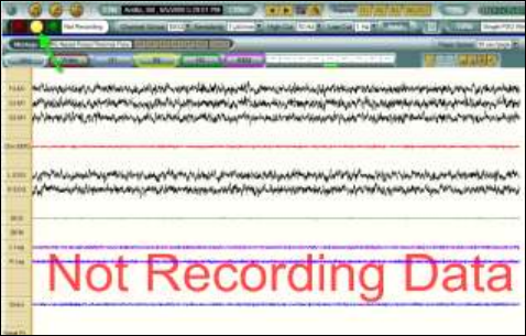
20. Monitor Mode. The monitor mode will allow the user to modify channel settings
(sensitivity, filter setting) before recording data. After entering all patient information, click
on the yellow button to start the monitor mode. The system will prompt the user that data is
not being recorded. Clicking on the monitoring mode before starting a recording will not
start the recording timer. Clicking on the monitoring mode during data collection will pause
data collection; however blank pages will be displayed in the recorded data.
Cadwell Easy III – Version 3.5
10
General Warnings and Precautions
Federal law restricts sale of this system to,
or on the order of, a physician.
Do not try to service internal parts of the
Easy III system. Only service by Cadwell,
Inc. or authorized bodies.
The operator must be trained to recognize
the difference between signal artifacts and
valid bio-signals caused by movements,
interference, or misplacement of sensors
or electrodes.
Inspect all cables before and after each use.
Discard cable if insulation is damaged or if
the cable or connectors are damaged in any
manner.
This manual provides an operational
summary for the Easy III system. It does
not provide clinical training. It is assumed
that the user has adequate clinical
training.
The proper use of this device, for its
intended use, can only be assured once all
instructions have been read and understood.
Contact Cadwell with Easy III operational
questions.
The system is not defibrillator proof.
Do not use the system in an MRI
environment.
The system is not designed to operate in
an explosive environment.
A possible loss of data can occur if acquiring
data on a machine that has a network data
folder.
Do not immerse the amplifier, remote
input box, power-communications
module, flash stimulator, and system
cables in liquid.
Do not use power strips with the system
unless they are connected downstream of an
isolation transformer.
The system is designed to be used with
one patient at a time. Do not connect
multiple patients to one amplifier.
Do not connect items which are not
specified as part of or for use with the Easy
III system.
Never place an isolation transformer on
the ground.
Do not exceed the medical isolation
transformer maximum load.
When attaching the Easy III system to a
patient, verify that the subject will not
become entangled in the wires. Do not
allow the electrode wires to wrap around
the patient's neck.
Do not use the isolation transformer to
power non-system components; it may
overload the transformer or defeat the
separation by providing additional leakage
sources.
Do not update Persyst software
components without Cadwell approval.
Do not exceed the medical isolation
transformer maximum load.
Do not plug non-medical electrical equipment in the patient environment directly into a wall
outlet. This may cause excessive leakage current in the patient environment.
11
EASY III TABLE OF CONTENTS
CADWELL EASY® III ............................................................................................................................................... 1
EASY III DATA ACQUISITION SYSTEM ............................................................................................................. 3
INTENDED USE .......................................................................................................................................................... 3
OPERATOR'S MANUAL INTENDED USE .................................................................................................................... 3
NEW FEATURES AND ENHANCEMENTS IN EASY III, VERSION 3.5 .......................................................................... 4
GENERAL WARNINGS AND PRECAUTIONS ............................................................................................................. 10
EASY HARDWARE ................................................................................................................................................. 13
SETUP INSTRUCTIONS ............................................................................................................................................. 13
COMPUTER-AMPLIFIER CONNECTION DIAGRAM ................................................................................................. 14
BASIC HARDWARE CONFIGURATION ..................................................................................................................... 15
EASY III HARDWARE COMPONENTS ...................................................................................................................... 17
EASY III AMPLIFIER OVERVIEW ........................................................................................................................... 19
EASY III POWER/COMMUNICATIONS MODULE ..................................................................................................... 25
EASY III DC AMPLIFIER ........................................................................................................................................ 29
EASY III PHOTIC STIMULATOR .............................................................................................................................. 29
EASY II AMPLIFIER HARDWARE ............................................................................................................................ 33
EASY II DC AMPLIFIER .......................................................................................................................................... 35
EASY II POWER COMMUNICATIONS UNIT ............................................................................................................. 35
EASY II DC AMPLIFIER SPECIFICATIONS .............................................................................................................. 36
EASY II REMOTE INPUT BOXES ............................................................................................................................. 36
EASY II PHOTIC STIMULATOR ............................................................................................................................... 37
EASY AMBULATORY ............................................................................................................................................... 40
EASY AMBULATORY HARDWARE .......................................................................................................................... 40
AMBULATORY RECORDER FEATURES, LEDS, CONNECTORS ............................................................................... 42
AMBULATORY BATTERY HOLDER ......................................................................................................................... 45
EASY AMBULATORY WIRELESS ............................................................................................................................. 49
EASY AMBULATORY WIRELESS HARDWARE ........................................................................................................ 49
AMBULATORY RECORDER FEATURES, LEDS, CONNECTORS ............................................................................... 51
WIRELESS AMBULATORY RECORDER RECHARGEABLE BATTERIES ................................................................... 54
EASY REMOTE INPUT BOXES ................................................................................................................................. 59
EASY III EASYNET MODULES* .............................................................................................................................. 62
EASYNET CABLE TESTER....................................................................................................................................... 65
MINIMUM COMPUTER HARDWARE REQUIREMENTS ............................................................................................ 67
Q-VIDEO CAMERA HARDWARE ............................................................................................................................. 69
IP CAMERA SETUP .................................................................................................................................................. 70
EASY III SOFTWARE ............................................................................................................................................. 72
PREPARING FOR SOFTWARE INSTALLATION ......................................................................................................... 72
OPERATING SYSTEM, 3RD PARTY SOFTWARE REQUIREMENTS ............................................................................. 72
INSTALLING EASY III SOFTWARE .......................................................................................................................... 73
SOFTWARE OVERVIEW ........................................................................................................................................... 95
CADWELL SCHEDULER OPTIONS ........................................................................................................................... 99
CLINICAL DATABASE OPTIONS ............................................................................................................................ 106
EASY III SYSTEM SETTING ................................................................................................................................... 107
AVERAGE REFERENCES ........................................................................................................................................ 114
FLASH PROGRAMS ................................................................................................................................................ 114
DATA MAPS .......................................................................................................... ERROR! BOOKMARK NOT DEFINED.
ACCESS SCRIPTS .................................................................................................. ERROR! BOOKMARK NOT DEFINED.
MANAGE USERS ................................................................................................... ERROR! BOOKMARK NOT DEFINED.
USER-DEFINED PSG EVENTS .............................................................................. ERROR! BOOKMARK NOT DEFINED.
PSG SETTINGS ..................................................................................................... ERROR! BOOKMARK NOT DEFINED.
PSG EVENT DETECTION SETTINGS .................................................................... ERROR! BOOKMARK NOT DEFINED.

Cadwell Easy III – Version 3.5
12
SELECTING A PROTOCOL .................................................................................... ERROR! BOOKMARK NOT DEFINED.
EDITING PROTOCOLS .......................................................................................... ERROR! BOOKMARK NOT DEFINED.
SETTING UP WORKSPACE WINDOWS .................................................................. ERROR! BOOKMARK NOT DEFINED.
ADDING, MODIFYING, AND CALIBRATING DC DEVICES .................................... ERROR! BOOKMARK NOT DEFINED.
RECORD MANAGER ............................................................................................. ERROR! BOOKMARK NOT DEFINED.
PREPARE A PATIENT FOR DATA COLLECTION ................................................... ERROR! BOOKMARK NOT DEFINED.
START EASY III PROCEDURE .............................................................................. ERROR! BOOKMARK NOT DEFINED.
EASY III TOOLBAR OPTIONS .............................................................................. ERROR! BOOKMARK NOT DEFINED.
MARKING EVENTS ............................................................................................... ERROR! BOOKMARK NOT DEFINED.
EASY STAMP ........................................................................................................ ERROR! BOOKMARK NOT DEFINED.
SLEEP EVENTS ..................................................................................................... ERROR! BOOKMARK NOT DEFINED.
SLEEP SUMMARY EVENTS ................................................................................... ERROR! BOOKMARK NOT DEFINED.
COMPUTER ASSISTED PSG EVENT DETECTORS ................................................ ERROR! BOOKMARK NOT DEFINED.
BOOKMARKS ........................................................................................................ ERROR! BOOKMARK NOT DEFINED.
Q-VIDEO .............................................................................................................. ERROR! BOOKMARK NOT DEFINED.
GENERATE A REPORT .......................................................................................... ERROR! BOOKMARK NOT DEFINED.
SELECT REPORT .................................................................................................. ERROR! BOOKMARK NOT DEFINED.
QUICKREPORT DOCUMENT ................................................................................ ERROR! BOOKMARK NOT DEFINED.
SAVE THE REPORT ............................................................................................... ERROR! BOOKMARK NOT DEFINED.
REPORT HEADER ................................................................................................. ERROR! BOOKMARK NOT DEFINED.
PERSYST TOOLS ................................................................................................... ERROR! BOOKMARK NOT DEFINED.
MAGIC MARKER .................................................................................................. ERROR! BOOKMARK NOT DEFINED.
MAGIC MARKER MENU OPTIONS ....................................................................... ERROR! BOOKMARK NOT DEFINED.
REVEAL SPIKE DETECTOR .................................................................................. ERROR! BOOKMARK NOT DEFINED.
SPIKE REVIEW ..................................................................................................... ERROR! BOOKMARK NOT DEFINED.
REVIEW RECORDS ............................................................................................... ERROR! BOOKMARK NOT DEFINED.
SCROLL THROUGH RECORDS .............................................................................. ERROR! BOOKMARK NOT DEFINED.
SAFETY INFORMATION ........................................................................................ ERROR! BOOKMARK NOT DEFINED.
ELECTROMAGNETIC COMPATIBILITY ................................................................ ERROR! BOOKMARK NOT DEFINED.
MAINTENANCE ..................................................................................................... ERROR! BOOKMARK NOT DEFINED.
CLEAN THE EASY III SYSTEM ............................................................................. ERROR! BOOKMARK NOT DEFINED.
TECHNICAL .......................................................................................................... ERROR! BOOKMARK NOT DEFINED.
CUSTOMER SUPPORT ........................................................................................... ERROR! BOOKMARK NOT DEFINED.
USING HELP FILES ............................................................................................... ERROR! BOOKMARK NOT DEFINED.
13
EASY HARDWARE
Setup Instructions
The Easy III system is comprised of several system components. Your particular configuration of
equipment may include amplifier hardware, cables, sensors, video equipment, and computer
hardware.
Unpack Easy Hardware
Inspect your shipping documentation. Verify that you have accounted for all boxes and
components shipped to you from Cadwell. If the total number of boxes delivered to your facility
does not match the total number of boxes listed on your shipping documents, please contact
Customer Service at Cadwell Labs.
Carefully unpack all hardware. Verify that you have completely removed all hardware, cables,
and documentation from each box. Place all documentation and shipping lists in a safe location
for future reference.
Your Cadwell authorized installer will connect all of the Easy equipment and verify that the
system is properly configured.
Unpack Computer Hardware
Inspect your shipping documentation. Verify you have accounted for all boxes and components
shipped to you from Cadwell Labs. Please complete all product registration forms and return
them to each hardware manufacturer as specified.
Your Cadwell authorized installer will set up your new computer hardware during the system
installation and training session.
If you have purchased your computer hardware from Cadwell Labs all Easy III software has been
previously installed by our configuration team.
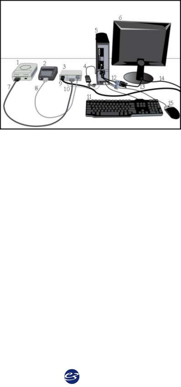
The illustration on the following page provides a simplified illustration showing how Easy III
amplifier hardware is connected to a computer.
Cadwell Easy III – Version 3.5
14
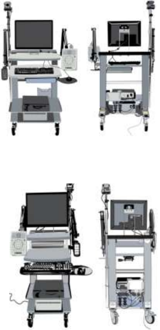
Computer-Amplifier Connection Diagram
1. Connect the Easy III Amplifier (1) to the Power/Com Module (3) with the Easy III Amplifier Cable (7).
2. Connect the Photic Stimulator (2) to the Power/Com Module (3) with the CPN Cable (8).
3. Connect the Power/Com Module (3) to the Computer (5) with the
4. Ground the Power/Com Module (3) to the Computer (5) with the grounding wire (10).
5. Plug in the video to USB adapter (4) to a USB port on the computer (5).
6. Connect the monitor (6) to the computer (5) with the video splitter cable (12) and the monitor cable
(13).
7. Connect the monitor (6) to a power supply with the AC Power Cord (14).
8. Connect the keyboard (11) to a USB port on the computer (5).
9. Connect the mouse (15) to a USB port on the computer (5).
10. Connect the Power/Com Module (3) to a power supply with the AC Power Cord (9). Press the On
button on the front of the Power/Com Module and verify the power LED is on.
11. Verify EasyNet Modules are connected. See EasyNet Module Connections.
15
Basic Hardware Configuration
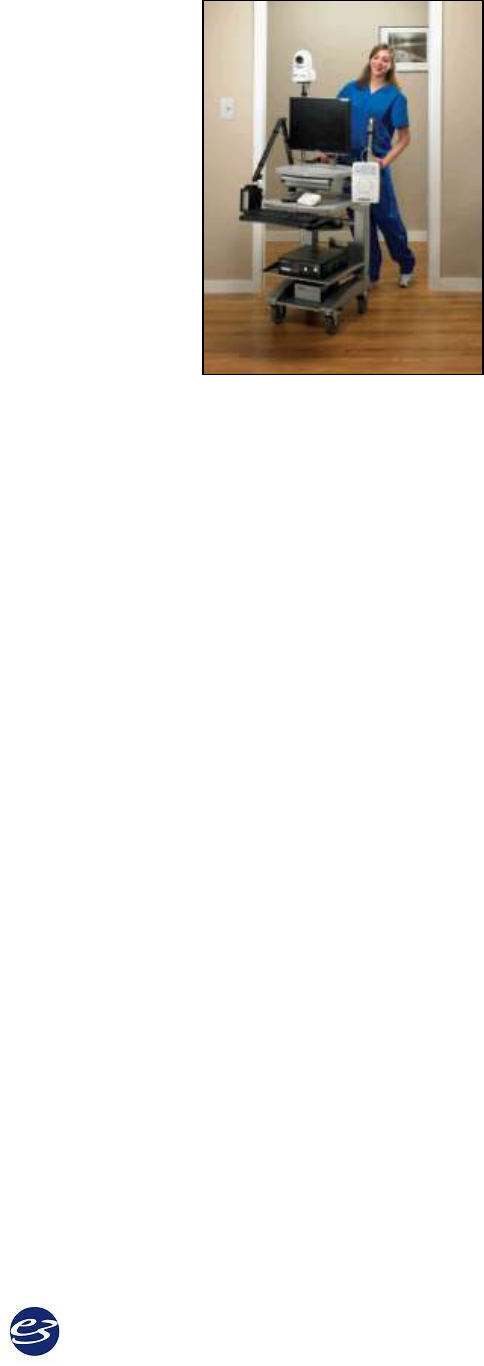
Easy hardware can be configured in multiple amplifier and system cart configurations to meet
your needs.
Patient Room/Recording Area
You can configure your Easy III hardware on a variety of carts and trolleys from Cadwell. The
following options are available:
Wide Trolley
The wide trolley is 38‛H x 29‛D x 30‛W. The cart is
shipped pre-assembled (U.S. shipments only). The wide
trolley has multiple adjustable height shelves, mounting
brackets for amplifier or flash stimulator articulating arms.
An optional LCD mounting bracket is available.
This cart is designed to handle large monitors, computers,
and printers. The wide trolley has several options,
including an accessory bag, isolation transformer, and an
extending keyboard tray.
Contact Cadwell to discuss all of the options available for this trolley.
Narrow Trolley
The narrow trolley is 38‛H x 29‛D x 24‛W. The cart is
shipped pre-assembled (U.S. shipments only). The narrow
trolley has multiple height-adjustable shelves, and mounting
brackets for amplifier or flash stimulator articulating arms.
An LCD mounting bracket is also available.
The narrow cart is designed to help you maneuver your
Easy system in environments with limited space. The cart's
options include an accessory bag, storage bin, isolation
transformer, and an extending keyboard tray. Contact
Cadwell to discuss all the options available for the narrow
trolley.
* Cart configurations and options are subject to change. Contact Cadwell if you have specific
questions about your cart configuration.
Cadwell Easy III – Version 3.5
16
Articulating Trolley Arms
There are two different articulating arms that can be used
with the wide and narrow trolleys. One arm is designed to
hold the Easy III 32 channel amplifier (or Easy II EEG
amplifier); the other articulating arm is designed to hold the
Easy III flash stimulator (or the Easy II flash stimulator). The
photograph displayed to the right shows the Easy III
amplifier photic stimulator mounted on articulating arms on
a trolley cart.
Printer Setup
All necessary printer drivers and software are already
installed on your computer from the Cadwell factory. There is no need for you to install any
additional drivers or software. Please put the CDs and documentation that came with your
printer in a secure place for future reference.
If you purchased your printer from a source other than Cadwell, you must install the printer
driver on your PC. Please refer to the instruction manual accompanying your printer for
instructions on printer setup and software installation.
Additional Setup Supplies
You may purchase additional items from Cadwell that can assist you in setting up and
configuring your equipment to allow optimal performance and patient comfort. Call Cadwell at
1.800.245.3001 for product information.
Hardware Overview
17
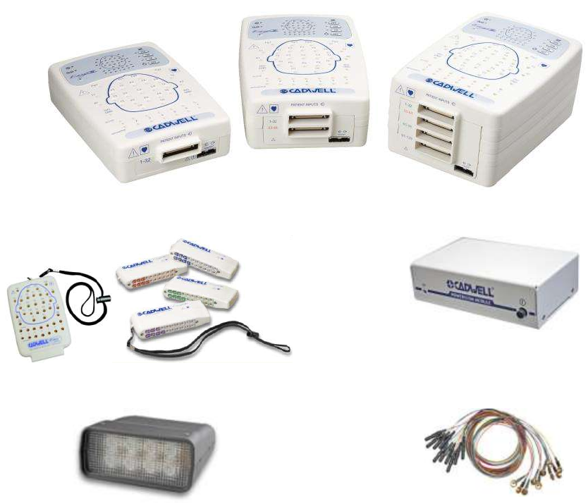
Easy III Hardware Components
The Easy III system is comprised of several system components. Your particular configuration of
equipment may include amplifier hardware, cables, sensors, video equipment, and computer
hardware.
Easy III Amplifiers
Remote Input Boxes
Power/Com Module
Photic Stimulator
Electrodes
Cadwell Easy III – Version 3.5
18
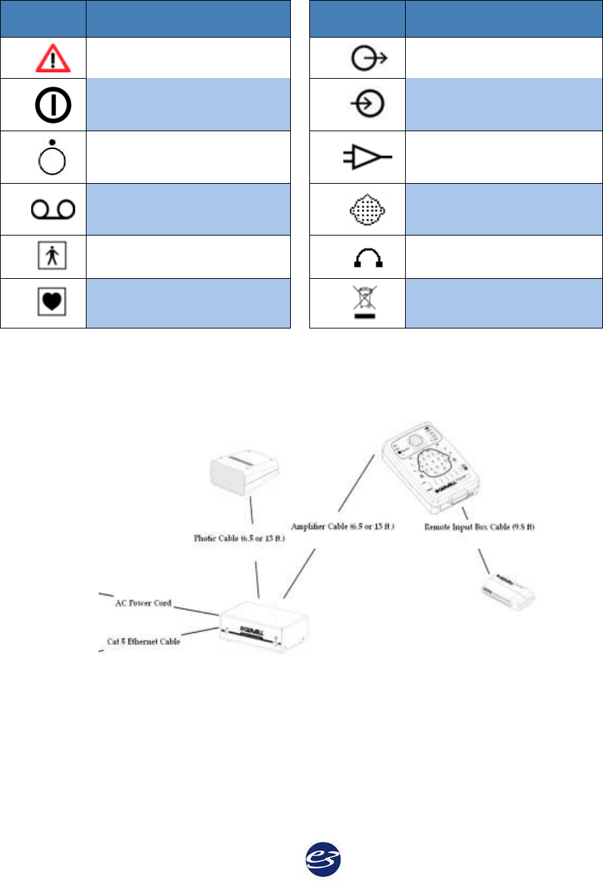
Easy III Device Symbols
Symbol
Description
Symbol
Description
See manual or help file
Input Signal
Power
Output Signal
Off
Amplifier
Recording
Patient Input
Connector
Type BF
Headphones Input
Type CF
WEEE Conformity
Easy III Cable Connections
19
Easy III Amplifier Overview
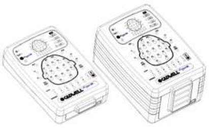
The basic Easy III amplifier includes 32 AC channels. Seven of these are bipolar and two
additional channels are ambient light detection channels. Eight DC channels may be added
internally. For studies requiring more recording channels, the amplifier may be expanded to
include 64 or 128 EEG channels.
The EasyNet expansion port allows additional channels to be added to the system, including
oximetry, heart rate, body position, accelerometers for limb movement, and multiple patient
event channels. In all, the Easy III has the capacity for more than 150 patient event channels.

Cadwell Easy III – Version 3.5
20
Easy III Amplifier Specifications
EEG Amplifier Inputs:
46 Channel Configuration: 32 EEG channels, capable of 12 EasyNet channels, ambient light,
and infrared light.
54 Channel Configuration: 32 EEG channels, 8 DC inputs, capable of 12 EasyNet channels,
ambient light, and infrared light.
86 Channel Configuration: 64 EEG channels, 8 DC inputs, capable of 12 EasyNet channels,
ambient light and infrared light.
150 Channel Configuration: 128 EEG channels, 8 DC inputs, capable of 12 EasyNet channels,
ambient light and infrared light.
Active/Reference Pairs:
7 (46 or 54 ch), 14 (86 ch), or 28 (150 ch) sets of inputs
Noise:
< 2uV , Mains noise rejection > 110 dB at 50 and 60 Hz
DC Inputs:
8 inputs (+/-) 10V, 200Hz storage rate
Photic Stimulator:
White LEDs. (1 – 60 Hz flash rate range)
ISO Ground Connectors:
2 inputs
Low Cut Filter:
Act/Ref pairs: 9 steps (0.032 – 10 Hz)
EEG channels: 8 steps (0.16-10 Hz)
High Cut Filter:
5 steps (15 – 100 Hz)
EEG Channel Sampling Rate:
4000 Hz per channel
EEG Channel Storage Rate:
250 Hz per channel
EEG Differential Input Impedance:
20 Mohm
EEG A/D Conversion System:
18 bit A/D Conversion System
EEG Sensitivity:
19 steps between 0.5 – 1000 uV/mm
Amplifier/Computer Interface:
Ethernet
LEDs:
-Power -Ethernet Link -Status
-Ethernet Data Transfer -EasyNet Connection -Recording
Transport and Storage Limits:
Temperature: -4°F to 149°F (-20°C to 65°C)
Relative Humidity: 10-90% non-condensing
Atmospheric Pressure: 500-1060 hPa
Operational Limits:
Temperature: +10° C (+50° F) to +40° C (104° F)
Relative Humidity: 30% to 75% non-condensing
Regulatory Approvals:
UL60601-1
CSA 601.1
EN 60601-1
EN 60601-1-1 (medical systems)
EN 60601-2-26 (EEG equipment)
EN 60601-1-2 (EMC)
EN 60601-1-4 (programmable electrical medical systems)
21
Easy III Amplifier Placement
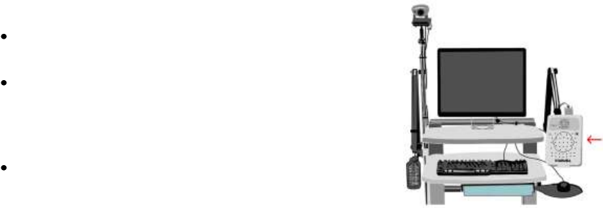
The Easy III Amplifier can connect to:
A 4-inch deep wall-mount bracket that can be attached
to a wall adjacent to the patient monitoring area.
The Easy III amplifier articulating arm. This arm can be
attached to a trolley cart. Screw the Amplifier Bracket
into the back of the Amplifier, and then connect it to the
articulating arm.
The amplifier can also be placed on a nightstand or table
adjacent to the patient.
Cadwell Easy III – Version 3.5
22
Easy III Amplifier LEDs
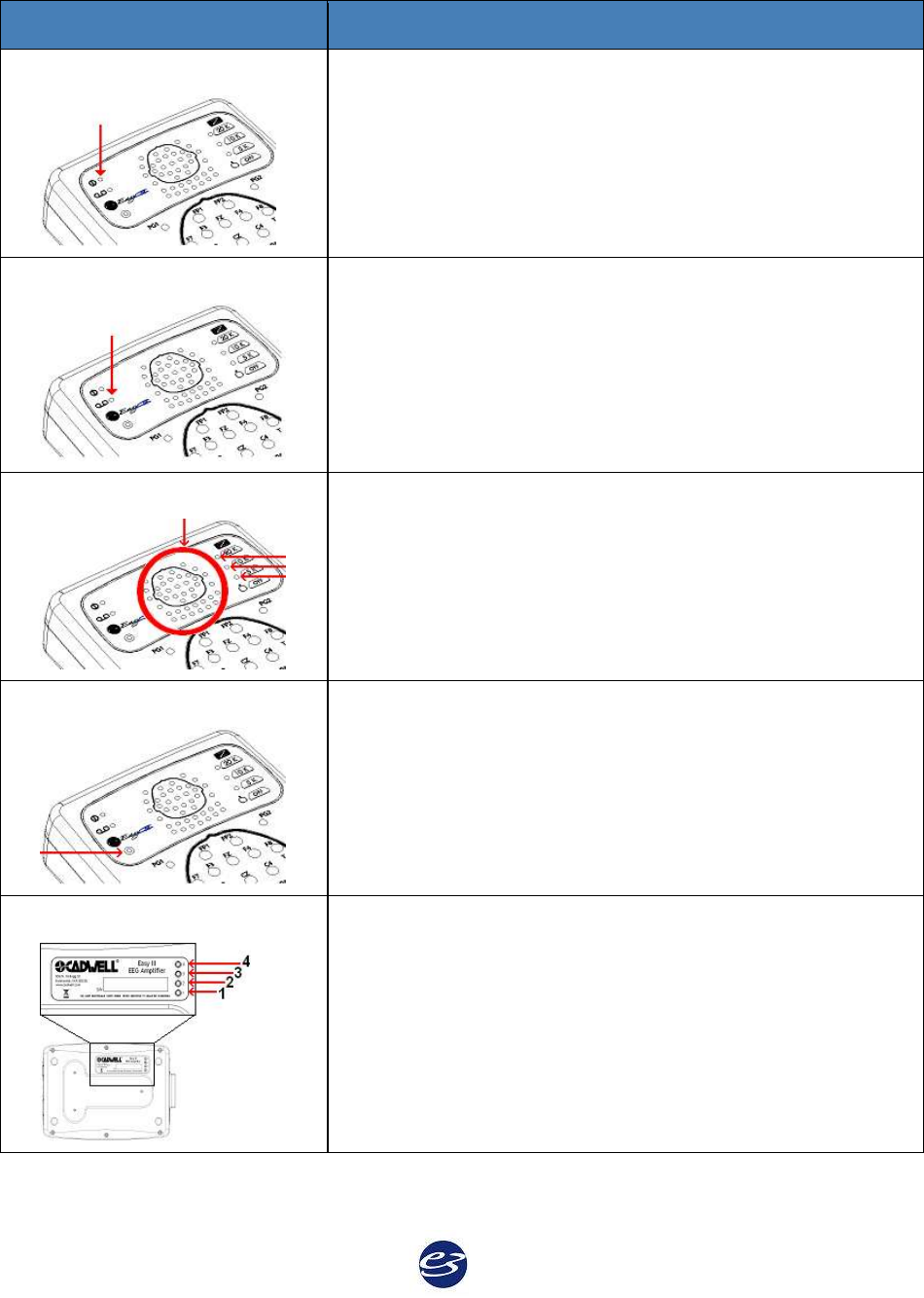
Easy III LEDs
Description
Power
The Power LED indicates that the amplifier is receiving power
from the Power/Com Module.
This LED flashes green at 1 Hz when there is idle power. It is solid
green during data collection.
Recording
The Recording LED indicates that the amplifier is collecting data.
Impedance
The Impedance LEDs indicate the impedance level for each EEG
input, ground input, and active reference pair input. Pressing the
adjacent 5K, 10K, or 20K button is illuminate a LED for any
corresponding input that has a higher impedance level than
selected. Pressing the OFF button will turn off the impedance
measurement feature. Note: The amplifier must be in the record
mode to use the impedance LEDs.
Ambient Light Detector
The Ambient Light Detector can detect when the ambient light
adjacent to the amplifier changes.
Amplifier Connection Status
LED 1, 3, and 4 indicate amplifier status. LED 2 is inactive.
23
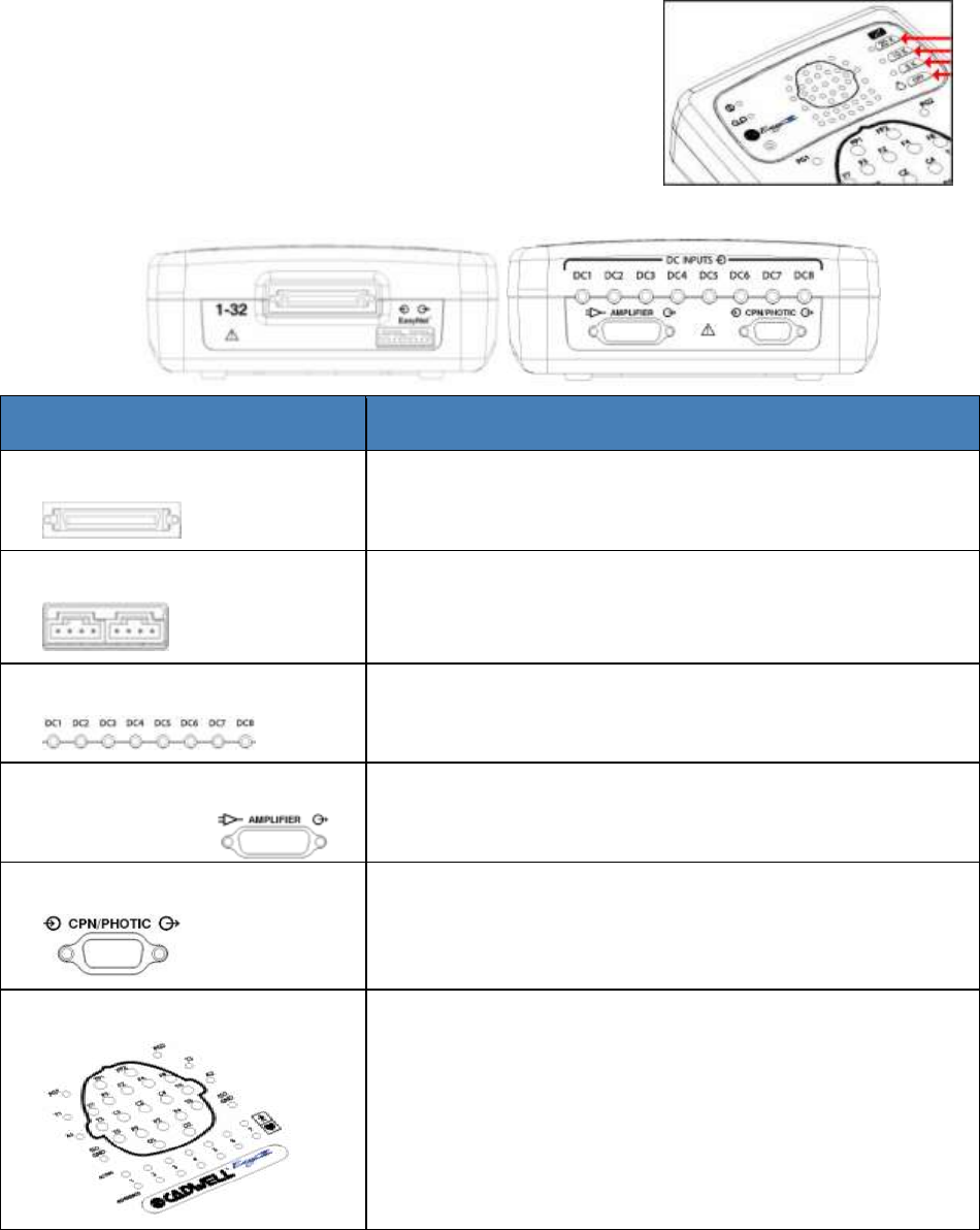
Easy III Amplifier Impedance Buttons
The 20K, 10K, 5K and OFF buttons on the Easy III amplifier
perform manual impedance checks. NOTE: The amplifier
must be recording data for the impedance buttons to be
operational.
The OFF button halts the impedance check. It does not turn off
the amplifier.
Easy III Amplifier Connectors and Cables
Easy III Amplifier Connectors
Description
Remote Inputs
Connects to Remote Input Boxes through the Remote
Input Box Cable.
EasyNet Expansion Ports
Add 12 or more optional channels, including oximetry,
oral/nasal airflow, body position, and multiple
accelerometers for limb movement.
DC Inputs
Add up to 8 internal DC channels.
Amplifier Power/Com Cable
Input
Connects to the Power/Com Module with a 2- or 4- meter
cable.
CPN/Photic Input
Supplies power and information to the Photic Stimulator
through the Photic Stimulator cable.
Electrode Ports
EEG electrodes and seven Act/Ref pair electrodes can be
plugged into the inputs on the top of the amplifier or into
a remote input box. The input connectors are designed for
0.059 inch (1.5mm) diameter molded safety connectors.
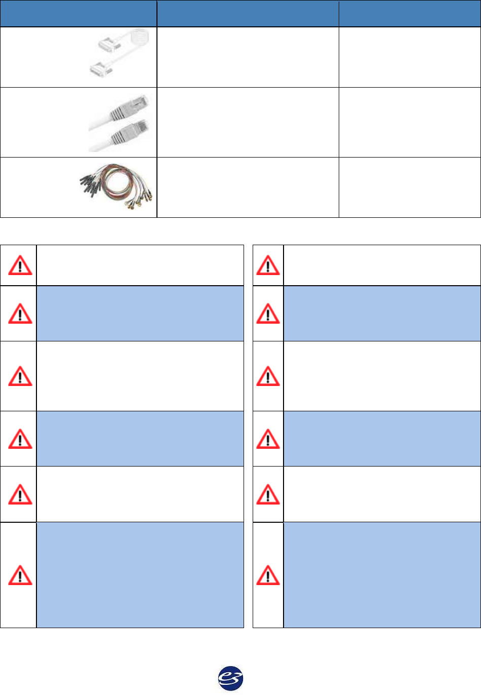
Cadwell Easy III – Version 3.5
24
Easy III Amplifier Cables
Description
Length
Amplifier
Cable
Connects the Easy III Amplifier
to the Power/Com Module.
6.5 or 13 feet (2 or 4
meters)
Cat 5 Cable
Connects the Power/Com
Module to network card in
computer. Straight-through RJ-
45, Cat 5 cable.
max 325 feet (99 meters)
Electrodes
Connects the patient to the
Remote Input boxes.
lengths and types vary
Easy III Amplifier Warnings & Precautions
Do not immerse the amplifier in liquid.
Do not use the system in an MRI
environment.
No user-serviceable parts inside. Service
by Cadwell Laboratories, Inc. and other
authorized bodies only.
Strictly adhere to the cleaning
instructions in this manual.
Inspect cables before and after each use.
Discard cable if insulation is damaged or
if the cable or connectors are damaged in
any manner. Test the system regularly.
The system is not designed to operate in
an explosive environment.
The system is not defibrillator-proof.
Use only Cadwell-approved mounting
hardware to attach the Easy III amplifier
to an articulating arm.
The system is designed to be used with
one patient at a time. Do not connect
multiple patients to one amplifier.
Use only Cadwell-approved cables for
connecting your Cadwell Easy III
hardware components.
External devices connected to DC
inputs must comply with IEC 60601-1
and all relevant collateral standards.
Sensors attached to EEG inputs to
monitor other functions must provide at
least basic insulation to ground and be
passive in nature or provide at least
double insulation if mains powered.
25
Easy III Power/Communications Module
Power/Com Module Overview
The Power-Communications (Power/Com) Module is the central connection point for the Easy III
and computer hardware for power supply and information exchange. The amplifier and photic
stimulator hardware plug into the power/com module, and the PC connects to the Power/Com
Module with an Ethernet cable to communicate with the amplifier and photic stimulator.
Easy III Power/Com Placement
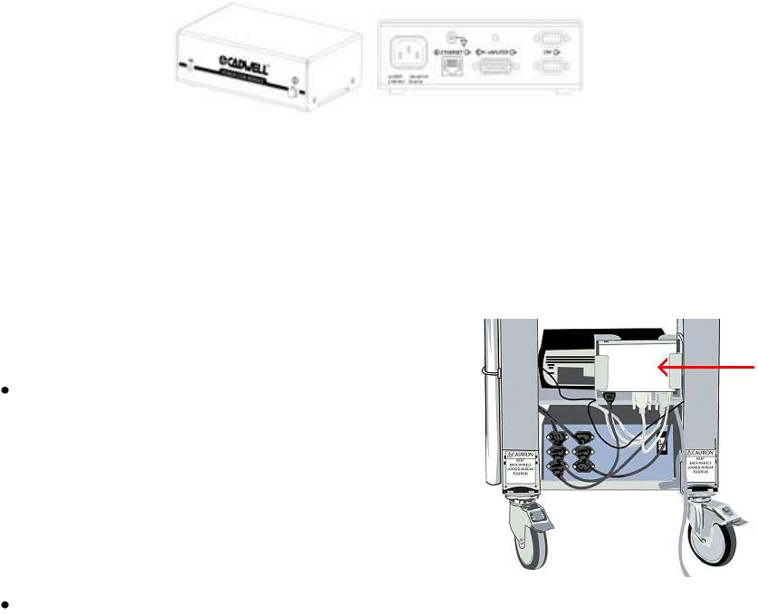
The Power/Communications module connects the Easy III
amplifier to its host computer.
In a cart configuration, the
Power/Communications Module can be mounted
to the cart with a Power/Communications Module
Holder Kit, placing it in proximity to the devices it
connects to: the PC, the Easy III Amplifier, and the
Isolation Transformer. The
Power/Communications Module also utilizes a
grounding wire, which attaches to the cart.
The Power/Communications module can also be placed adjacent to the patient on a night
stand or on the floor.
Note: Verify the power communication module is placed in a location where the patient will not
trip or become entangled in the wires.
Cadwell Easy III – Version 3.5
26
Easy III Power/Com LEDs
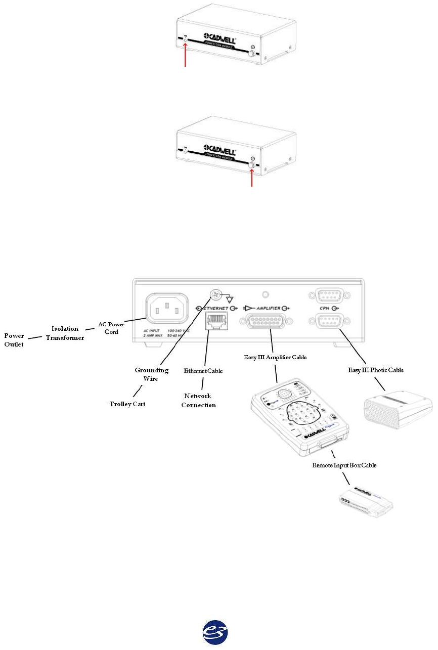
Green LED- ON indicates that the Power/Com module is receiving power.
Easy III Power/Com Buttons
The Power button turns the Power/Com Module and the Amplifier on or off.
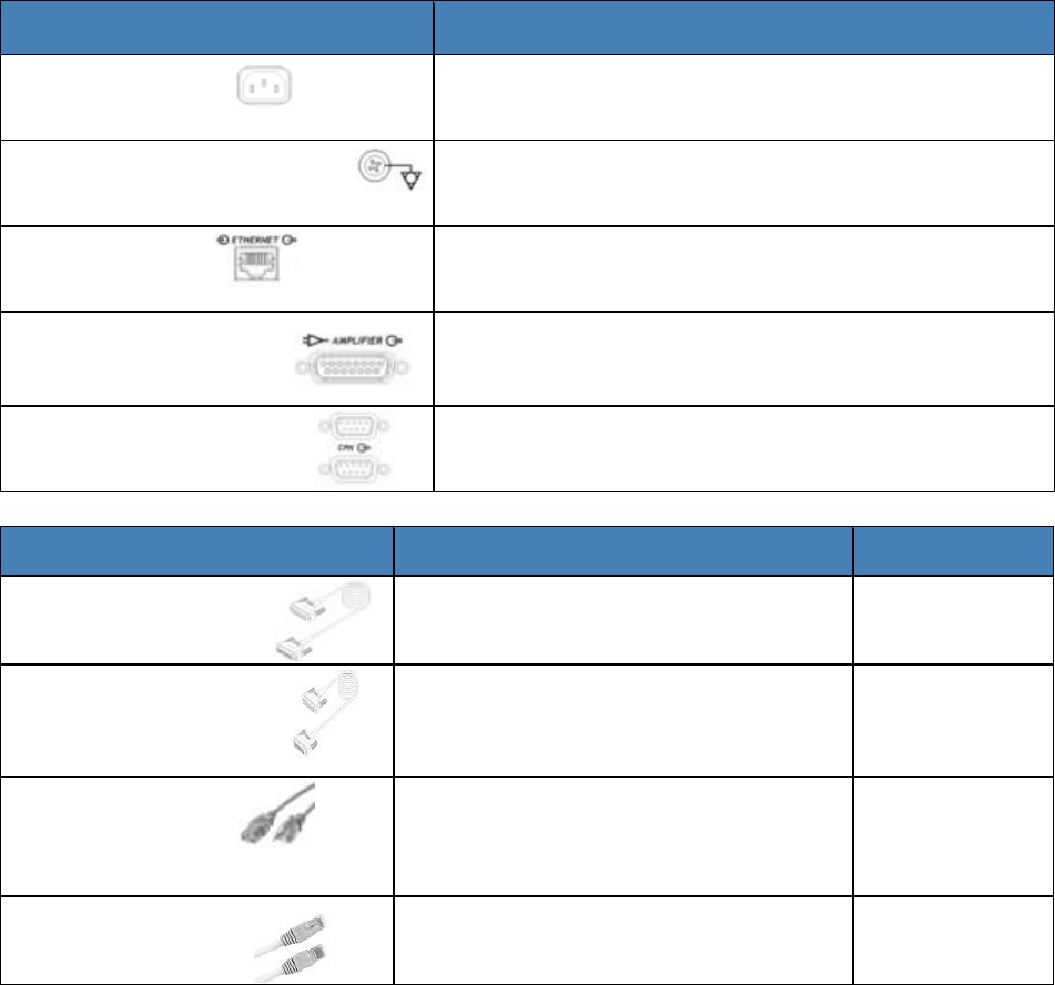
Easy III Power/Com Connectors and Cables
27
Easy III Connectors and Cables
Easy III Power/Com Connectors
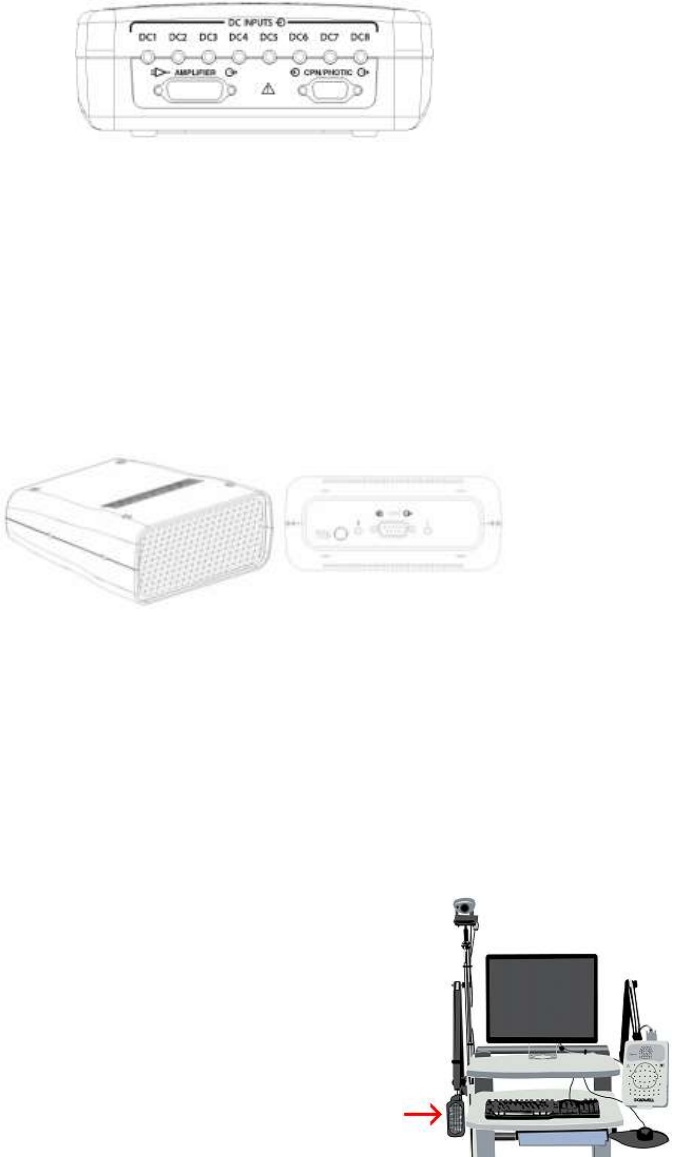
Description
AC Power Port
Inputs power from the AC power cord. 100-240VAC,
1 AMP Max, 50-60Hz.
Voltage Equalization Screw
To reduce noise, use a grounding wire from the
thumb-screw grounding post to the cart.
Ethernet Port
Connects Easy III hardware to Easy III software in PC.
Isolated 10/100 Base T, Straight-through RJ-45.
Amplifier Cable Port
Connects to the male end of the Amplifier Cable.
CPN Port
Connects to the Photic Stimulator cable (either
connector may be used with the photic stimulator)
Easy III Power/Com Cables
Description
Length
Amplifier Cable
Connects the Easy III Amplifier to the
Power/Com Module.
6.5 or 13 feet/
2 or 4 meters
Photic Cable
Connects the Easy III Photic
Stimulator to the Power /Com
Module.
6.5 or 13 feet/
2 or 4 meters
AC Power Cord
Supplies power to the Power /Com
Module. Connect to an isolation
transformer.
8 feet/ 2.4
meters
Ethernet Cable
Connects the Power /Com Module to
the network card in computer.
325 feet/ 99
meters
Cadwell Easy III – Version 3.5
28
Easy III Power/Com Warnings & Precautions
Do not immerse the Power/Com
module or its cables in liquid.
Cleaning instructions in this manual
need to be strictly adhered to.
No user-serviceable parts inside.
Service by Cadwell Laboratories, Inc.
and other authorized bodies only.
The system is not designed to
operate in an explosive environment.
Inspect cables before and after each
use. Discard cable if insulation is
damaged or if the cable or connectors
are damaged in any manner. Verify
the patient will not trip or become
entangled in the
Power/Communications cables.
Use only Cadwell-approved cables
for connecting your Cadwell Easy III
hardware components.
The system is not defibrillator proof.
Only use with one patient at a time.
Potential Equalization terminal may
only be used for noise reduction.
Potential equalization does not qualify
as a redundant protective earth
connection for non-medical electrical
equipment.
A possible shock hazard can be
created by the summation of leakage
currents when several equipments
are interconnected.
Do not use the system in an MRI environment.
Cadwell Easy III
29
Easy III DC Amplifier
The 54, 86 and 150 channel Easy III Amplifier are equipped with eight (8) internal DC inputs
configured to collect multiple channels such as oximetry, patient event swithch, pulse rate, air
flow, pressure, CPAP leak and pH. The input voltage range is - 10V to + 10V.
The DC Amplifier connects to a DC device with the DC Amplifier Cable, which is available in a
variety of lengths.
Easy III Photic Stimulator
Photic Stimulator Overview
The Easy III Photic Stimulator is an ancillary piece of equipment used during EEG recording to
provide visual stimulation to a patient. It can be run manually or through default or custom Flash
Programs.
The photic stimulator has a Run/Stop button on the back of the flash stimulator. For manual use,
point the photic stimulator at the patient at the appropriate distance from the patient, and push
the Run button. The Easy system will use the first default flash program. Push the button again
to stop the flash program.
Photic Stimulator Placement
The photic stimulator connects to the CPN/Photic port on the
Cadwell Power/Com Module or the Easy III Amplifier.
The Easy III Photic Stimulator is designed to attach to a photic
stimulator arm mounted on a trolley cart. The photic
stimulator has a 2- or 4-meter cable that connects to the
Power/Com Module.
Cadwell Easy III – Version 3.5
30
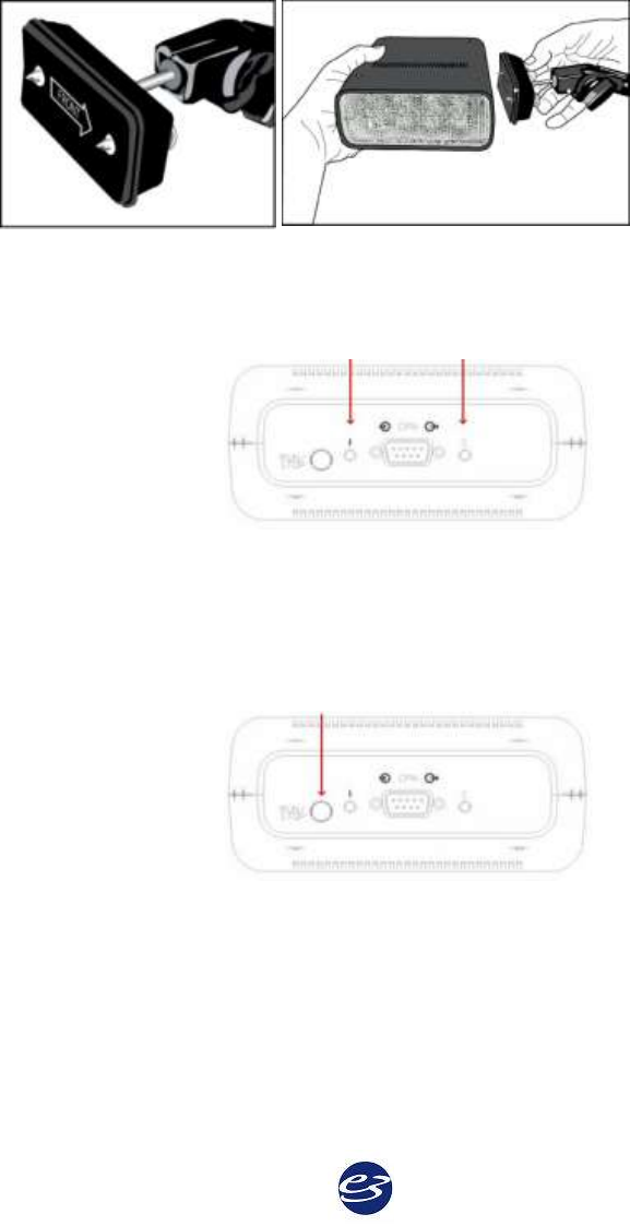
Attach Photic Stimulator to Articulating Arm
1. Mount the articulating arm onto the trolley cart.
2. Line up the screws of the articulating arm with the sockets on the side of the photic
stimulator, with the arrow pointing towards the flash.
3. Connect the screws and sockets, and finger-tighten until secure.
Photic Stimulator LEDs
Green Yellow
The green LED flashes at 1 Hz during flash stimulation.
The yellow LED flashes at 1 Hz when power is connected, but flash stimulation is idling.
Photic Stimulator Buttons
Run/Stop
To run manually, or to turn off quickly, push the Run/Stop button.
31
Photic Stimulator Connectors and Cables
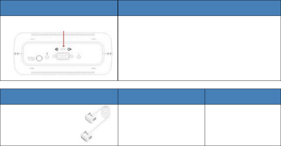
Photic Stimulator Connector
Description
CPN Input
Attaches the Photic Stimulator to the Amplifier or
the Power/Com Module with the Photic Cable.
Easy III Cables
Description
Length
Easy III Photic
Cable
Used to connect the Easy
III Photic Stimulator to
the Power/ Com
Module.
6.5 or 13 feet (2 or 4
meters)
Cadwell Easy III – Version 3.5
32
Photic Stimulator Warnings & Precautions
Use of the Cadwell Easy III Photic
Stimulator may induce seizures in
epileptic or epilepsy-prone patients.
Persons who are photosensitive to light
may have convulsions, seizures, or a
myoclonic reaction to the photic
stimulator.
The operator must be trained to
recognize EEG waveforms and patient
symptoms consistent with reactions to
photic stimulation. The operator must
follow laboratory medical policies and
procedures when using the flash
stimulator to care for the patient
undergoing photic stimulation.
The system is not defibrillator proof.
Do not use in an MRI environment.
The system is not designed to operate in
an explosive environment.
Do not immerse the photic stimulator in
liquid.
The Photic Stimulator must be at least 12
inches (30 cm) from the patient’s eyes. If
used on an anesthetized patient, a means
should be provided to ensure that the
patient's eye lids remain closed.
The photic stimulator is not intended
for patient connection, but meets IEC
60601-1 leakage requirements in normal
and single-fault conditions. The photic
stimulator is appropriate for use in the
patient environment.
Cleaning instructions in this manual
need to be strictly adhered to.
Use only Cadwell-approved cables for
connecting your Cadwell Easy III
hardware components.
Use only Cadwell-approved mounting
hardware to attach the Easy III flash
stimulator to an articulating arm.
The system is designed to be used with
one patient at a time.
Inspect cables before and after each use.
Discard cable if insulation is damaged or
if the cable or connectors are damaged in
any manner.
No user-serviceable parts inside. Service
by Cadwell Laboratories, Inc. and other
authorized bodies only.
When using the photic stimulator on a
Cadwell photic stimulator arm, do not
allow the arm or the stimulator to come
in contact with the patient.
Use caution when extending, moving or
adjusting the photic stimulator arm. Do
not pinch your hands and fingers in the
connectors, articulating joints, or
extending joints on the photic
stimulator arm.
33
Easy II Amplifier Hardware
Easy II Intended Use
The Easy II system is intended for use by a physician or trained technician under the supervision
of a physician for the acquisition of EEG and other polygraphic channels. The intended
recording environment for the Easy II is the hospital, clinic, physician’s office, and other testing
environments.
Easy II Amplifier Hardware
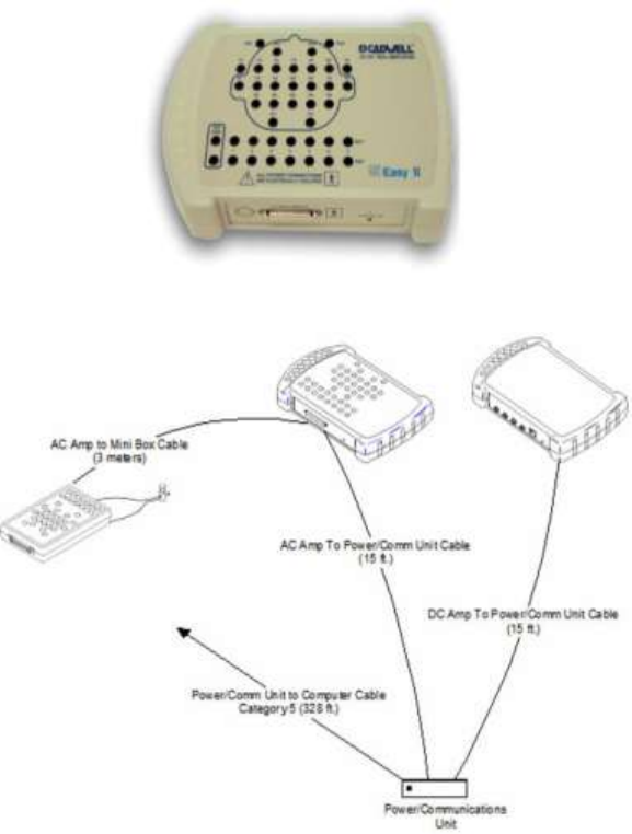
The Easy II amplifier can be used to collect up to 32 channels of EEG and/or polysomnographic
data. EEG electrodes can be plugged into the connectors on the top of the amplifier, or plugged
into a remote input box. The input connectors are designed for 0.059-inch (1.5mm) diameter
molded safety connectors. The Easy II Amplifier connects to a Power Communications module
with a 3 meter cable.
Easy II Amplifier Connection Overview

Cadwell Easy III – Version 3.5
34
Easy II Amplifier Specifications
EEG Amplifier Inputs:
32 Channel Configuration: 25 EEG only channels and 7 channels which are switchable between
individual active/reference pairs and EEG channels
Active/Reference Pairs:
7 inputs on the 32 channel amplifier
Noise:
< 2uV
DC Inputs:
4 (+10/- 5V)
Photic Stimulator:
1 – 25 Hz flash rate range
ISO Ground Connectors:
2 inputs
EEG Common Mode Rejection:
100 Db at 50 or 60 Hz
Low Cut Filter:
Act/Ref pairs: 9 steps (0.032 – 10 Hz)
EEG channels: 8 steps (0.16-10 Hz)
High Cut Filter:
5 steps (15 – 100 Hz)
EEG Channel Sampling Rate:
2300 Hz per channel
EEG Channel Storage Rate:
200 Hz per channel
EEG Differential Input Impedance:
20K M ohm
EEG A/D Conversion System:
16 bit A/D Conversion System
EEG Sensitivity:
19 steps between 0.5 – 1000 uV/mm
Amplifier/Computer Interface:
Ethernet
Operational Limits:
Temperature:
+10º C (+50º F) to +40º C (+104º F)
Relative Humidity:
30% - 75%
Atmospheric Pressure:
700 hPa to 1060 hPa
Transport and Storage Limits:
Temperature:
Do not expose to temperatures below -20º C (-4º F) or above 65º C (149º F)
Relative Humidity:
Do not expose to relative humidity below 10% or above 90% non-condensing
Atmospheric Pressure:
500 hPa to 1060 hPa
Regulatory Approvals:
UL60601-1
CSA 601.1
EN 60601-1
EN 60601-1-1 (medical systems)
EN 60601-2-26 (EEG equipment)
EN 60601-1-2 (EMC)
EN 60601-1-4 (programmable electrical medical systems)
35
Easy II DC Amplifier
The Easy II DC amplifier has 4 DC inputs. The amplifier also has an internal Nonin oximeter and
body position senor input. The Easy II DC Amplifier is connected to the Easy II Power
Communications Module with a cable that plugs into the Auxiliary connector on the DC
Amplifier.
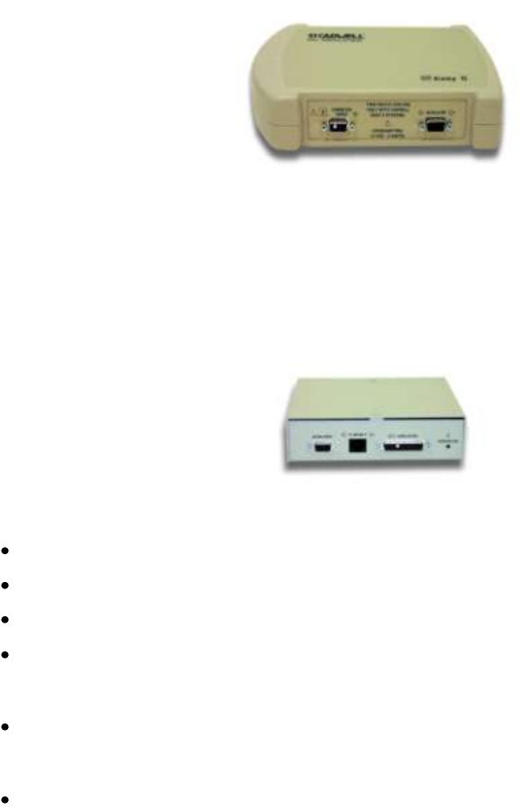
Easy II Power Communications Unit
The Power-Communications (power com) Module is the central connection point for the Easy II
hardware. The amplifier and photic stimulator hardware plug into the power/com module. The
module has a thumb screw on the back panel to allow a ground cable to reduce noise.
Connectors
AC Input – 100-240 VAC, 1 AMP Max, 50-60 Hz
Ethernet – Isolated 10/100 Base T, Straight-through RJ-45
Amplifier – 24 pin, submini-D connector.
Auxiliary – 15 pin, submini-D connector for photic stimulator.
LED 's
Power On/Off LED
Cable
4 meter cable with 15 pin sub mini-D connectors
Cadwell Easy III – Version 3.5
36
Easy II DC Amplifier Specifications
Connectors
• One Sub D 9 pin connector for oximetry input.
• One Sub D 15 pin connector for auxiliary input.
• One RJ45 connector for body position sensor input.
• DC Inputs - Four 1/8 inch female stereo connectors.
LEDs
Power - The power on LED indicates that the unit is receiving power from the power-
communications module.
DC Inputs
4 Inputs (5V to -10V)
Easy II Remote Input Boxes
The Remote Input Boxes allow electrode extension 10 to 15 feet from the amplifier.
Top panel Remote Input Boxes are labeled for 10-20 EEG inputs.
Side-input Remote Input Boxes are also available.
Input Box Details
25 EEG only channels and 7 active/reference pair inputs with 0.059-inch (1.5mm)
diameter molded safety connectors.
A recessed 50 pin mini-D connector is used for the remote input box cable.
Remote Input Box Cable (3 m.)
Each cable has a 50 pin, locking mini-D connector at each end of the cable.
37
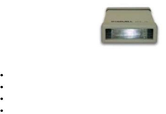
Easy II Photic Stimulator
The Easy II Photic Stimulator is designed to attach to a photic stimulator arm mounted on a
trolley/cart. The photic stimulator has a 4 meter cable that connects to the Cadwell Power Com
Module.
Photic Stimulator Details
Flash Rate/Intensity - 1 – 25 Hz/0.72 J/flash
LEDs - Power
Connectors - 15 pin mini-D
Cable - 4 meter cable with 9 pin sub mini-D connector
Cadwell Easy III – Version 3.5
38
Easy II Warnings and Cautions
Do not immerse the amplifier, remote input box,
power-communications module, flash stimulator,
and system cables in liquid.
Use only Nonin SpO2 sensors with the Easy II DC
Amplifier. Though Cadwell has tested the Nonin
8000J sensor with the EasyNet SpO2 module, other
sensors have not been tested or validated.
No user serviceable parts inside the Easy II
Amplifier or remote input boxes. Service by
Cadwell Laboratories, Inc. and other authorized
bodies only.
Discontinue using any module or sensor if the
patient exhibits any allergic reactions to adhesive
or materials.
The system is not defibrillator proof.
Cleaning instructions in this manual need to be
strictly adhered to. Always disconnect equipment
from power source and patient before cleaning.
The system is not designed to operate in an
explosive environment.
Inspect cables before and after each use. Discard
cable if insulation is damaged or if the cable or
connectors are damaged in any manner.
Use only Cadwell approved cables.
Do not use the system in an MRI environment.
The system is designed to be used with one patient
at a time. Do not connect multiple patients to one
amplifier.
Use only Cadwell approved mounting hardware
to attach the Easy II amplifier to an articulating
arm.
Use caution when extending, moving, or adjusting
the Easy II Amplifier Arm. Verify that your hand
and fingers will not be pinched in the connectors,
articulating and extending joints on the Amplifier
Arm.
When attaching the Easy II system to a recording
subject, verify that the subject will not become
entangled in the wires. Do not allow the electrode
wires to wrap around the subjects neck.
The Easy II remote Input Box inputs are Type CF
rated. CF rating ensures that no current higher
than 50uA flows to or from the applied part if
mains voltage is inadvertently connected to the
patient.
The Easy II amplifier inputs are Type CF rated. CF
rating ensures that no current higher than 50uA
flows to or from the applied part if mains voltage
is inadvertently connected to the patient.
When using the Easy II photic stimulator on a
Cadwell Photic Stimulator Arm, do not allow the
arm or photic to come in contact with the patient.
Conductive parts of electrodes and their
connectors, including the neutral electrode, should
not contact other conductive parts including earth.
The Photic stimulator is not intended for patient
connection, but meets IEC 60601-1 leakage
requirements in normal and single fault
conditions. The photic stimulator is appropriate
for use in the patient environment.
Cleaning instructions in this manual need to be
strictly adhered to. Always disconnect equipment
from power source and patient before cleaning.
The Cadwell Easy II photic stimulator must be at
least 30 cm away from the patient’s eyes. If used
on an anesthetized patient a means should be
provided to ensure that the eye lids remain closed.
Inspect cables before and after each use. Discard
cable if insulation is damaged or if the cable or
connectors are damaged in any manner.
39
Easy II Warnings and Cautions continued.
The use of the Cadwell Easy II flash stimulator
may induce seizures in epileptics or people prone
to epilepsy. Persons who are photosensitive to
light may have convulsions, seizures, or a
myoclonic reaction to the photic stimulator. The
operator must be trained to recognize EEG
waveforms and patient symptoms that are
consistent with a patient’s reaction to photic
stimulation. The operator must follow laboratory
medical policies and procedures when using the
flash stimulator to care for the patient undergoing
photic stimulation.
Do not immerse the photic stimulator or its cable
in liquid.
Potential Equalization terminal may only be used
for noise reduction. Potential equalization terminal
DOES NOT qualify as a redundant protective
earth connection for non medical electrical
equipment.
Use caution when extending, moving, or adjusting
the Cadwell Photic Stimulator Arm. Verify that
your hand and fingers will not be pinched in the
connectors, articulating and extending joints on
the Photic Stimulator Arm.
This manual provides an operational summary for
the Easy II system. It does not provide clinical
training. It is assumed that the user has adequate
clinical training.
The Power Com Module is not intended for
patient connection, but meets IEC 60601-1 leakage
requirements in normal and single fault
conditions. The Power Com Module is appropriate
for use in the patient environment.
Cadwell Easy III – Version 3.5
40
Easy Ambulatory
Ambulatory Intended Use
The Easy Ambulatory system is intended for use by a physician or trained technician under the
supervision of a physician for the acquisition of EEG and other polygraphic channels. The
intended recording environment for the Easy Ambulatory is the home, hospital, and other testing
environments.
Easy Ambulatory Hardware
The Easy Ambulatory system is comprised of three different modules, the recorder, battery
holder, and amplifier.
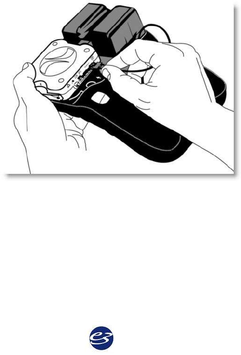
The Ambulatory Recorder and Battery Holder
The recorder is a small, lightweight module that uses compact flash memory to record patient
data. The recorder utilizes EasyNet technology to connect to multiple amplifier modules used to
amplify EEG and other physiological channels. The recorder is worn by the patient in a small
waist mounted pouch. The illustration below shows the recorder in the pouch. The EasyNet
cable from the amplifier is plugged into the side of the recorder. The battery holder is a
lightweight module used to hold the batteries that power the recorder and amplifier. Batteries
can be quickly replaced by removing the battery cover from the battery holder. The recorder is
mounted on the battery holder, and then placed in the Ambulatory recorder pouch for data
collection.
41
The Ambulatory Amplifier
The Ambulatory amplifier is a compact module that serves as a connector box and amplifier for
EEG and other physiological channels. The amplifier uses EasyNet technology to send data to
the recorder. The amplifier has multiple EEG inputs and active reference pair inputs. The
amplifier can be worn by the patient on a small chest/shoulder strap or on the waist belt provided
with the Easy system. The illustration below shows the amplifier with an EasyNet cable plugged
into the amplifier.
Ambulatory Amplifier LEDs, Connectors
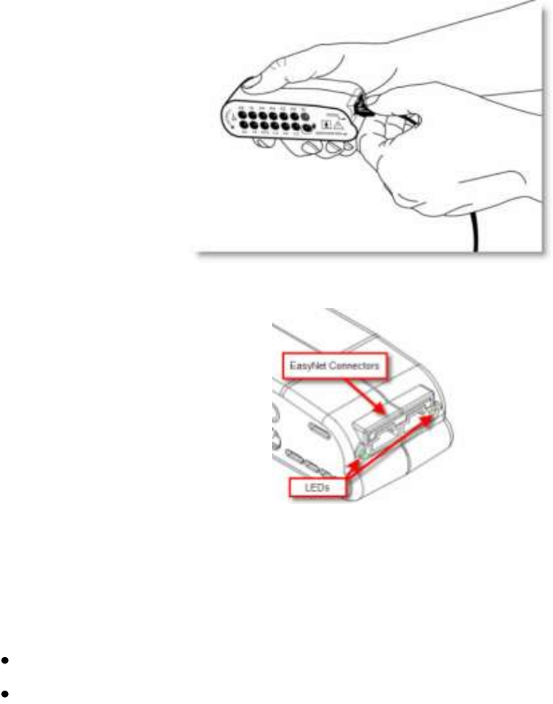
Ambulatory EasyNet Connectors
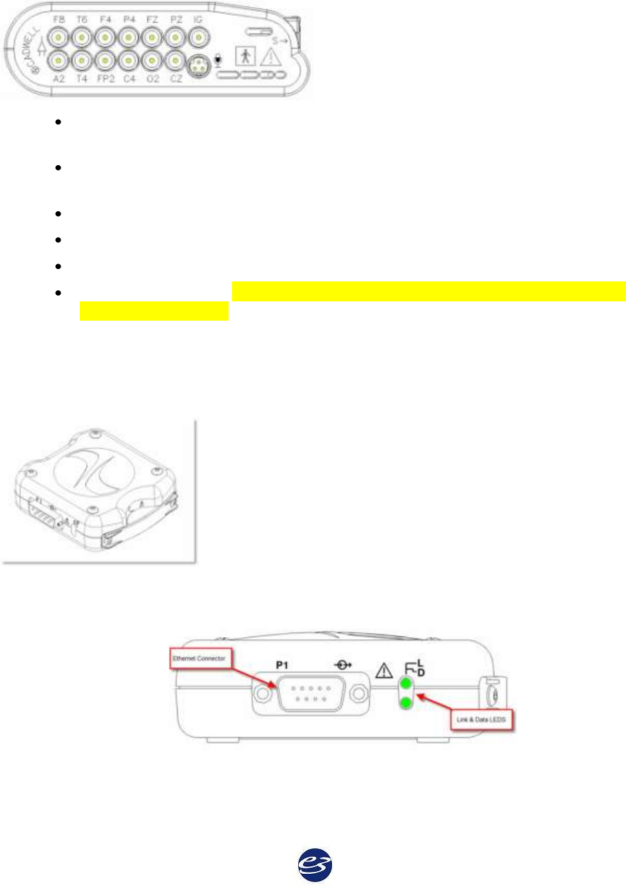
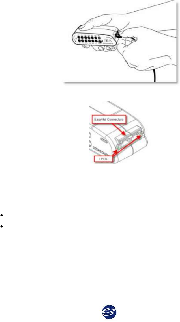
An EasyNet cable can be used to connect the Amplifier to the Ambulatory Recorder. Other
EasyNet modules can be plugged in to the other EasyNet connector on the Amplifier.
Ambulatory LEDs
S Yellow Status LED. Lights or flashes to indicate error condition.
I Green LED. Flashes to indicate power is being received from the recorder.
Cadwell Easy III – Version 3.5
42
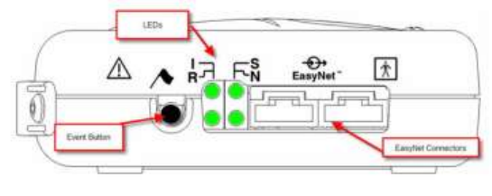
Ambulatory Electrode input connectors
FP1, FP2, F3, F4, F7,F8, T3,T4, T5, T6, A1, A2, C3, C4, P3, P4, O1, O2, FZ, CZ, PZ
International 10-20 lead placement descriptors used on the Easy Amplifier
IG x2, 1A, 1R, 2A, 2R, Voice Event Additional input descriptors placed on the Easy
Amplifier.
IG - Isolated Ground (x 2)
1A – 1R – Active Reference Pair
2A – 2R – Active Reference Pair
Voice event connector. The Voice Event input for the microphone is not supported in
Easy III, Version 3.2.54.
Ambulatory Recorder Features, LEDs, Connectors
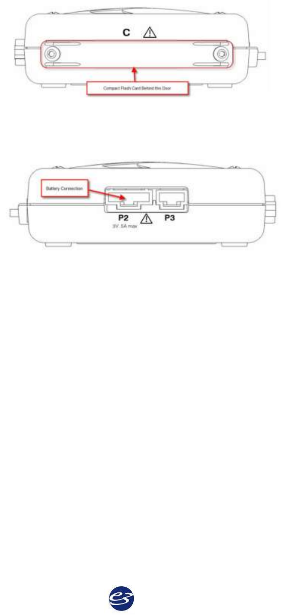
Recorder – 3 Dimensional View
Recorder – P1 Ethernet Connector
An ethernet adapter is attached to this connector for data downloading and data review.
43
Recorder – ‘D’ LED
The Data (D) LED indicates data is being transferred between the recorder and the computer.
Recorder – ‘L’ LED
The Link (L) LED indicates that the recorder has established an ethernet connection to the
computer.
Recorder – Event Button
The event button allows the patient to time synchronize an event during data collection.
For each button press, the recorder will record a time-synchronized event during data collection.
If the button is pressed for 4 seconds while the recorder is attached to a computer, a signal will be
sent to the network card identifying the recorder.
Recorder – ‘I’ LED
The ‘I’ LED indicates that the recorder is receiving power from the batteries.
Recorder – ‘S’ LED
The Status (S) LED flashes when an error condition is detected.
Recorder – ‘R’ LED
The EasyNet (R) LED flashes one time per second during data collection.
Recorder – ‘N’ LED
The EasyNet (N) LED flashes when an EasyNet error condition is detected.
Cadwell Easy III – Version 3.5
44
Recorder – EasyNet Connector
The EasyNet connector allows a cable connection from the recorder to other modules such as the
Amplifier/Connector module.
Recorder – ‘C’ Door
The Compact (C) Door can be removed to access the compact flash card. Cadwell recommends
that the compact flash door remain attached to the recorder during data collection.
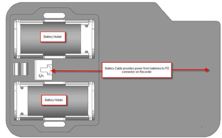
Recorder – P2 Connector
The P2 Connector is for the battery connection. Connect the battery cable from the battery holder
to the P2 connector on the recorder.
Recorder – P3 Connector
The P3 connector is reserved for future use.
45
Ambulatory Battery Holder
The Ambulatory Battery Holder is placed in the Ambulatory Recorder/Battery Holder pouch. A
white battery cable connects the battery power to the Ambulatory Recorder.

Cadwell Easy III – Version 3.5
46
Easy Ambulatory Specifications
EEG Amplifier Inputs:
21 inputs
Active/Reference Pairs:
2 sets of inputs
ISO Ground Connectors:
2 inputs
EEG Channel Sampling Rate:
3200 Hz per channel
EEG Channel Storage Rate:
200 Hz per channel
EEG Differential Input Impedance:
20K M ohm
EEG A/D Conversion System:
16 bit A/D Conversion System
Battery Power
2 ‘C’ or ‘D’ alkaline batterries
Recording Time/Battery Life
29 hours per set of ‘C’ cells
70 hours per set of ‘D’ cells
Data Storage/Memory Capacity
+ 165 hours with 4GB CF
Amplifier/Computer Interface:
Ethernet
Operational Limits:
Temperature:
+10º C (+50º F) to +40º C (+104º F)
Relative Humidity:
30% - 95% non-condensing
Regulatory Approvals:
UL601-1 2003
CSA 601.1 1990
EN 60601-1:1990 + A1:1993 + A2:1995 + A13:1996
EN 60601-1-1:2001 (medical systems)
EN 60601-2-26:1994 (EEG equipment)
EN 60601-1-2:2001 (EMC)
EN 60601-1-4:1996 (programmable electrical medical systems)
EN ISO 114971:2000 (risk)
47
Ambulatory Warnings and Cautions
Federal law restricts sale of this system to, or
on the order of, a physician.
High levels of static discharge can cause a
momentary pause in data collection.
No user serviceable parts inside. Service by
Cadwell Laboratories, Inc. and other
authorized bodies only.
Inspect EasyNet cables before and after each use.
Discard cable if insulation is damaged or if the
cable or connectors are damaged in any manner.
Inspect battery cable before and after each use.
Discard cable if insulation is damaged or if the
cable or connectors are damaged in any
manner.
Do not immerse the recorder, amplifier, battery
holder, or EasyNet Modules in liquid. Do not
attempt to use any Ambulatory system
components if they have been immersed in
liquid. The system is not water resistant or
splash proof. The contact of liquids with the
internal parts and connectors of the Cadwell
Easy Ambulatory 2 system should be avoided at
all times.
Caution must be taken to ensure that cables do
not encircle the patient's neck or entangle the
patient in any way.
The operator must be trained to be able to
recognize the difference between signal artifact
and valid bio-signals caused by movements,
interference, or misplacement of sensors or
electrodes.
The system is not defibrillator proof.
Do not use the system in an MRI environment.
Cleaning instructions in this manual need to be
strictly adhered to.
When applying the stockinet to the patient,
verify that the stockinet is not covering the
patient’s eyes, nose, mouth, or ears. Verify that
the stockinet does not entangle the patient’s
neck, restrict airflow, or restrict circulation.
When attaching the Easy Ambulatory 2 system
to a recording subject, verify that the subject
will not become entangled in the wires. Do not
allow the electrode wires to wrap around the
subject’s neck. Instruct the patient in the
proper way to wear the Easy Ambulatory
system and not become entangled.
The system is not designed to operate in an
explosive environment.
Do not remove compact flash card if the
recorder has power or is actively collecting
data.
Inspect EasyNet cables before and after each use.
Discard cable if cable insulation is damaged or if
the cable or connectors are damaged in any
manner.
Do not place recorder on a television, radio, or
CPAP device.
Use only Cadwell authorized cables and
accessories.
Always place the recorder and battery holder
in the Easy Ambulatory Pouch when collecting
patient data.
Type BF, IC601 Isolation
The EEG electrode connectors are only
designed for 1.5 mm touch proof connectors.
Do not autoclave.
Cadwell Easy III – Version 3.5
48
Ambulatory Warnings and Cautions continued.
Do not connect more than one
amplifier/Connector box to the Recorder.
When using the amplifier to collect data, verify
that the amplifier has been placed in a Cadwell
authorized pouch. Verify the amplifier has been
securely attached to the amplifier belt or
chest/shoulder strap.
Use only alkaline batteries, or those
recommended by Cadwell Labs.
Do not mix battery types.
Only use batteries authorized by Cadwell
Laboratories, Inc.
Do not re-use old batteries.
Do not store batteries in battery holder.
Remove batteries after use.
Inspect battery cable before and after each use.
Discard cable if insulation is damaged or if the
cable or connectors are damaged in any manner.
Do not re-use battery holder if battery leakage
has occurred.
Use only replacement fuses authorized by
Cadwell. An extra fuse is located on the battery
holder.
Do not use the battery holder without the
battery cover.
Do not immerse battery holder in liquid.
49
Easy Ambulatory Wireless
Ambulatory Wireless Intended Use
The Easy Ambulatory wireless system is intended for use by a physician or trained technician
under the supervision of a physician for the acquisition of EEG and other polygraphic channels.
The intended recording environment for the Easy Ambulatory Wireless is the home, hospital,
and other testing environments.
Easy Ambulatory Wireless Hardware
The Easy Ambulatory Wireless system is comprised of two different modules, the wireless
recorder and the amplifier.
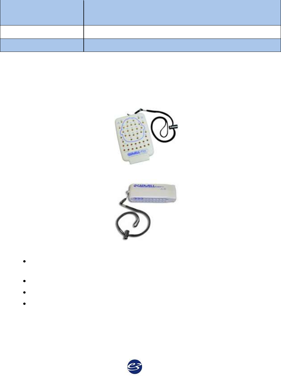
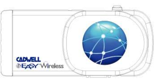
The Ambulatory Wireless Recorder
The wireless recorder is a small, lightweight module that uses compact flash memory to store
patient data. The recorder has an internal antenna that can be used to transfer recorded data
wirelessly to a host system. The recorder also has a wired Ethernet connector to allow the
recorder to be directly connected to a host computer. The recorder utilizes EasyNet technology to
connect to multiple wired amplifier modules used to amplify EEG and other physiological
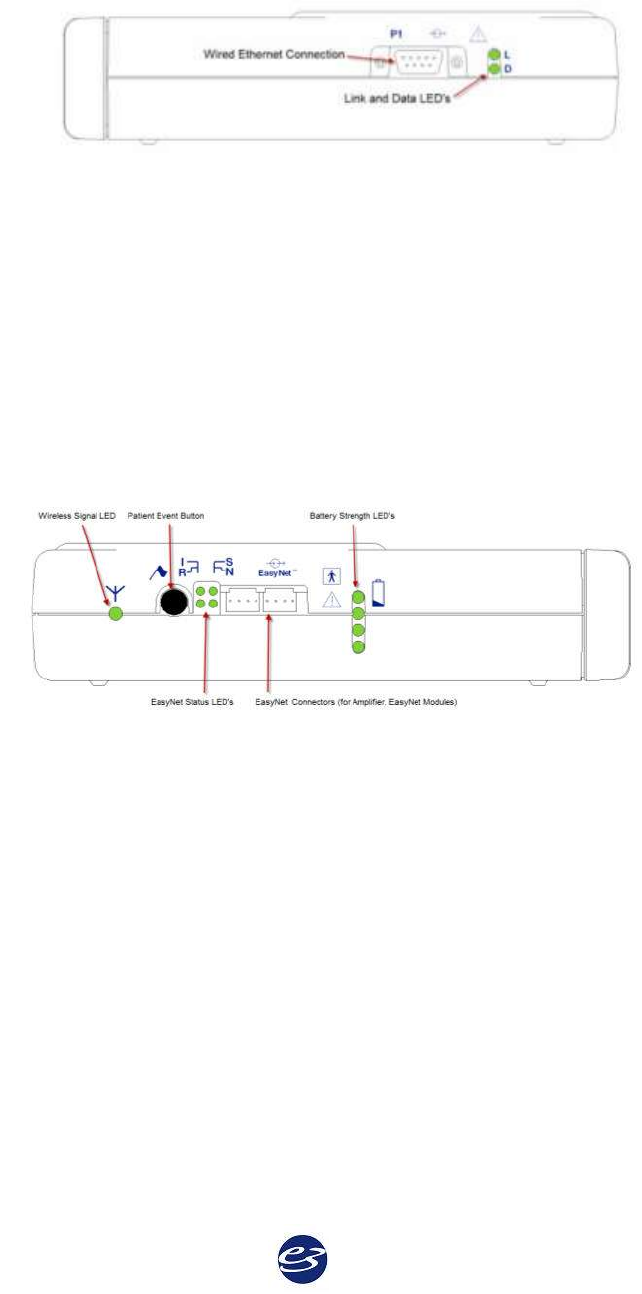
channels. The recorder is worn by the patient in a small waist mounted pouch. The illustration
below shows the top side of the wireless recorder.
Cadwell Easy III – Version 3.5
50
The Ambulatory Amplifier
The Ambulatory amplifier is a compact module that serves as a connector box and amplifier for
EEG and other physiological channels. The amplifier uses EasyNet technology to send data to
the recorder. The amplifier has multiple EEG inputs and active reference pair inputs. The
amplifier can be worn by the patient on a small chest/shoulder strap or on the waist belt provided
with the Easy system. The illustration below shows the amplifier with an EasyNet cable plugged
into the amplifier.
Ambulatory Amplifier LEDs, Connectors
Ambulatory EasyNet Connectors
An EasyNet cable can be used to connect the Amplifier to the Ambulatory Recorder. Other
EasyNet modules can be plugged in to the other EasyNet connector on the Amplifier.
Ambulatory LEDs
S Yellow Status LED. Lights or flashes to indicate error condition.
I Green LED. Flashes to indicate power is being received from the recorder.
51
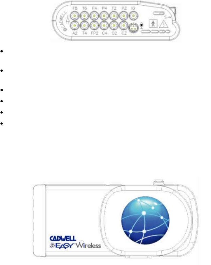
Ambulatory Electrode input connectors
FP1, FP2, F3, F4, F7,F8, T3,T4, T5, T6, A1, A2, C3, C4, P3, P4, O1, O2, FZ, CZ, PZ
International 10-20 lead placement descriptors used on the Easy Amplifier
IG x2, 1A, 1R, 2A, 2R, Voice Event Additional input descriptors placed on the Easy
Amplifier.
IG - Isolated Ground (x 2)
1A – 1R – Active Reference Pair
2A – 2R – Active Reference Pair
Voice event connector. The Voice Event input for the microphone is not supported in
Easy III, Version 3.3.
Ambulatory Recorder Features, LEDs, Connectors
Wireless Recorder – Top Panel View
Cadwell Easy III – Version 3.5
52
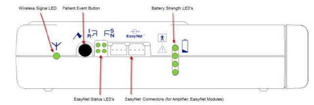
Wireless Recorder – Side View, P1 Ethernet Connector
The Power/Com cable from the Power/Com module is attached to this connector for a wired
connection to initialize the recorder, monitor data, download data and recharge the batteries.
Recorder – ‘D’ LED
The Data (D) LED indicates data is being transferred between the recorder and the computer.
Recorder – ‘L’ LED
The Link (L) LED indicates that the recorder has established an ethernet connection to the
computer.
Wireless Recorder – Side View, EasyNet Connection, Event Button, Status LED’s
Wireless Recorder – Event Push Button on Side of Recorder
The event button allows the patient to time synchronize an event during data collection.
For each button press, the recorder will record a time-synchronized event during data collection.
If the button is pressed for 4 seconds while the recorder is attached to a computer, a signal will be
sent to the network card identifying the recorder.
53
Recorder – Wireless Signal LED
The EasyNet wireless signal LED will be on when the recorder is wirelessly attached to the host
computer.
Recorder – ‘I’ LED
The ‘I’ LED indicates that the recorder is receiving power from the batteries or Power/Com. This
LED will flash rapidly when the battery levels are critically low.
Recorder – ‘S’ LED
The Status (S) LED flashes when an error condition is detected.
Recorder – ‘R’ LED
The EasyNet (R) LED flashes one time per second during data collection.
Recorder – ‘N’ LED
The EasyNet (N) LED flashes when an EasyNet error condition is detected.
Recorder – Battery Strength LED’s
All LEDs will be on when the batteries are completely charged. As the available battery power is
reduced, fewer LED’s will be on. When the battery levels are at critically low levels, the ‘I’ LED
will flash rapidly to indicate low battery power.
Recorder – EasyNet Connectors
The EasyNet connector allows a cable connection from the recorder to other modules such as the
Amplifier/Connector module.
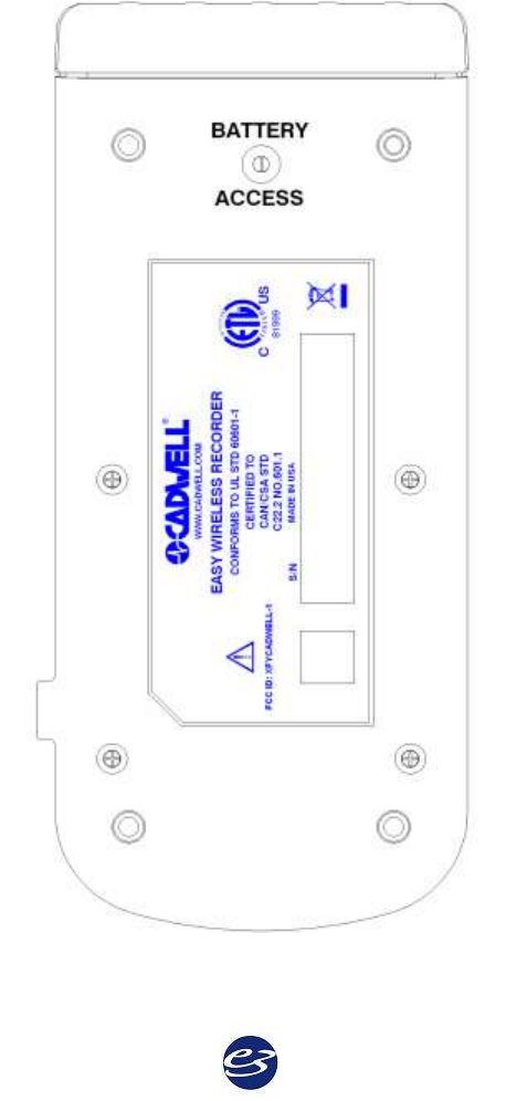
Cadwell Easy III – Version 3.5
54
Wireless Ambulatory Recorder Rechargeable Batteries
The Wireless Ambulatory rechargeable (Lithium Iron Phosphate) batteries are located in Wireless
Recorder. The batteries do not need to be removed for recharging. The batteries are recharged
when the Power/Com cable from the Power/Com module is plugged into the P1 connector and
the Power/Com is turned on.
To replace the batteries, remove the battery access screw located on the bottom of the wireless
recorder. The battery compartment will slide out of the recorder for replacement.
Ambulatory Wireless Recorder – Bottom View
55
Cadwell Easy III – Version 3.5
56
Easy Ambulatory Wireless Specifications
EEG Amplifier Inputs:
21 inputs
Active/Reference Pairs:
2 sets of inputs
ISO Ground Connectors:
2 inputs
EEG Channel Sampling Rate:
3200 Hz per channel
EEG Channel Storage Rate:
200 Hz per channel
EEG Differential Input Impedance:
20K M ohm
EEG A/D Conversion System:
16 bit A/D Conversion System
Battery Type:
Lithium Iron Phosphate with nearly 2000 discharge life cycles
Recording Time:
Nominally 4-8 hours. Battery recording time will vary based on the number of EasyNet
modules attached to the system. The system uses an adaptive power management approach to
provide power to the wireless antenna. If the wireless signal is weak, additional power will be
provided to the wireless to improve signal transmission.
Data Storage/Memory Capacity:
+ 165 hours with 4GB CF
Wireless Signal/Range
802.11 b\g, 200 ft. range in non obstructed environment
Amplifier/Computer Interface:
1. Wired Ethernet connection for Recorder Initialization, Impedance Measurement, Live
View, Battery Charging, or;
2. Wireless Ethernet (802.11b\g) for Live Viewing
Operational Limits:
Temperature:
+10º C (+50º F) to +40º C (+104º F)
Relative Humidity:
30% - 95% non-condensing
Regulatory Approvals:
UL601-1 2003
CSA 601.1 1990
EN 60601-1:1990 + A1:1993 + A2:1995 + A13:1996
EN 60601-1-1:2001 (medical systems)
EN 60601-2-26:1994 (EEG equipment)
EN 60601-1-2:2001 (EMC)
EN 60601-1-4:1996 (programmable electrical medical systems)
EN ISO 114971:2000 (risk)
FCC ID: XFY CADWELL-1
57
Ambulatory Wireless Warnings and Cautions
Caution: Exposure to Radio Frequency
Radiation
This device emits radio frequency radiation. The
output of this device is below acceptable FCC skin
absorption rate levels if used according to
manufacturer’s instructions.
Do not place the recorder in any other pack or
pouch than that supplied with or recommended by
Cadwell. Use of packs or pouches other than those
specified or approved by Cadwell could alter the
Radio Frequency emission pattern and intensity.
This device complies with part 15 of the FCC Rules.
Operation is subject to the following two conditions:
(1) This device may not cause harmful interference, and
(2) this device must accept any interference received,
including interference that may cause undesired
operation.
Warning: Changes or modifications not expressly
approved by the party responsible for compliance could
void the user’s authority to operate the equipment.
The maximum performance for wireless is derived
from IEEE Standard 802.11 specifications. Actual
performance can vary, including lower wireless
network capacity, data throughput rate, range and
coverage. Performance depends on many factors,
conditions and variables, including distance from
the access point, volume of network traffic,
building materials and construction, operating
system used, interference and other adverse
conditions.
Do not immerse the recorder, amplifier, battery holder,
or EasyNet Modules in liquid. Do not attempt to use
any Ambulatory system components if they have been
immersed in liquid. The system is not water resistant or
splash proof. The contact of liquids with the internal
parts and connectors of the Cadwell Easy Ambulatory 2
system should be avoided at all times.
Federal law restricts sale of this system to, or on the
order of, a physician.
High levels of static discharge can cause a momentary
pause in data collection.
When attaching the Easy Ambulatory system to a
recording subject, verify that the subject will not
become entangled in the wires. Do not allow the
electrode wires to wrap around the subject’s neck.
Instruct the patient in the proper way to wear the
Easy Ambulatory system and not become
entangled.
Dispose the batteries in accordance with applicable local
laws. Li-ion batteries may be subject to federal, state or
local regulations. Batteries should be discharged fully
prior to disposal. The battery terminals should be
capped to prevent a short circuit.
No user serviceable parts inside. Service by
Cadwell Laboratories, Inc. and other authorized
bodies only.
Inspect EasyNet cables before and after each use.
Discard cable if insulation is damaged or if the cable or
connectors are damaged in any manner.
Caution must be taken to ensure that cables do not
encircle the patient's neck or entangle the patient in
any way.
The operator must be trained to be able to recognize the
difference between signal artifact and valid bio-signals
caused by movements, interference, or misplacement of
sensors or electrodes.
The system is not defibrillator proof.
Do not use the system in an MRI environment.
Do not open or disassemble the batteries.
Type BF, IC601 Isolation
Do not place recorder on a television, radio, or
CPAP device.
Use only Cadwell authorized cables and accessories.
Cadwell Easy III – Version 3.5
58
Always place the recorder in the Easy Ambulatory
Pouch when collecting patient data.
The system is not designed to operate in an explosive
environment.
The EEG electrode connectors are only designed for
1.5 mm touch proof connectors.
Do not autoclave or immerse the recorder in liquid.
Do not connect more than one amplifier/Connector
box to the Recorder.
Cleaning instructions in this manual need to be strictly
adhered to.
Batteries should remain in the wireless recorder for
storage.
Do not use the recorder if battery leakage has occurred.
Only use rechargeable batteries authorized by
Cadwell Laboratories, Inc.
Do not attempt to re-charge batteries outside of the
wireless recorder.
Inspect the recorder before each use. Do not use
the recorder if any visible damage is present to the
recorder.
Do not use the wireless recorder if the battery cover is
not secured with the set screw on the bottom panel of
the recorder.
When applying the stockinet to the patient, verify
that the stockinet is not covering the patient’s eyes,
nose, mouth, or ears. Verify that the stockinet does
not entangle the patient’s neck, restrict airflow, or
restrict circulation.
When using the amplifier to collect data, verify that the
amplifier has been placed in a Cadwell authorized
pouch. Verify the amplifier has been securely attached
to the amplifier belt or chest/shoulder strap.
59
Easy Remote Input Boxes
Remote Input Boxes Overview
The Remote Input Boxes allow electrode extension
10 to 20 feet from the amplifier.
Top panel Remote Input Boxes are labeled for 10-20 EEG inputs.
The top panel input box is compatible with Easy II and Easy III
amplifier hardware.
Side-input Remote Input Boxes are color-coded and labeled for:
10-20 EEG inputs
Inputs 1-32
Inputs 33-64
Inputs 65-96
Inputs 97-128
Remote Input Boxes Placement
Remote Input Boxes connect to the Easy Amplifiers
with a detachable 10-foot (3-meter) cable.
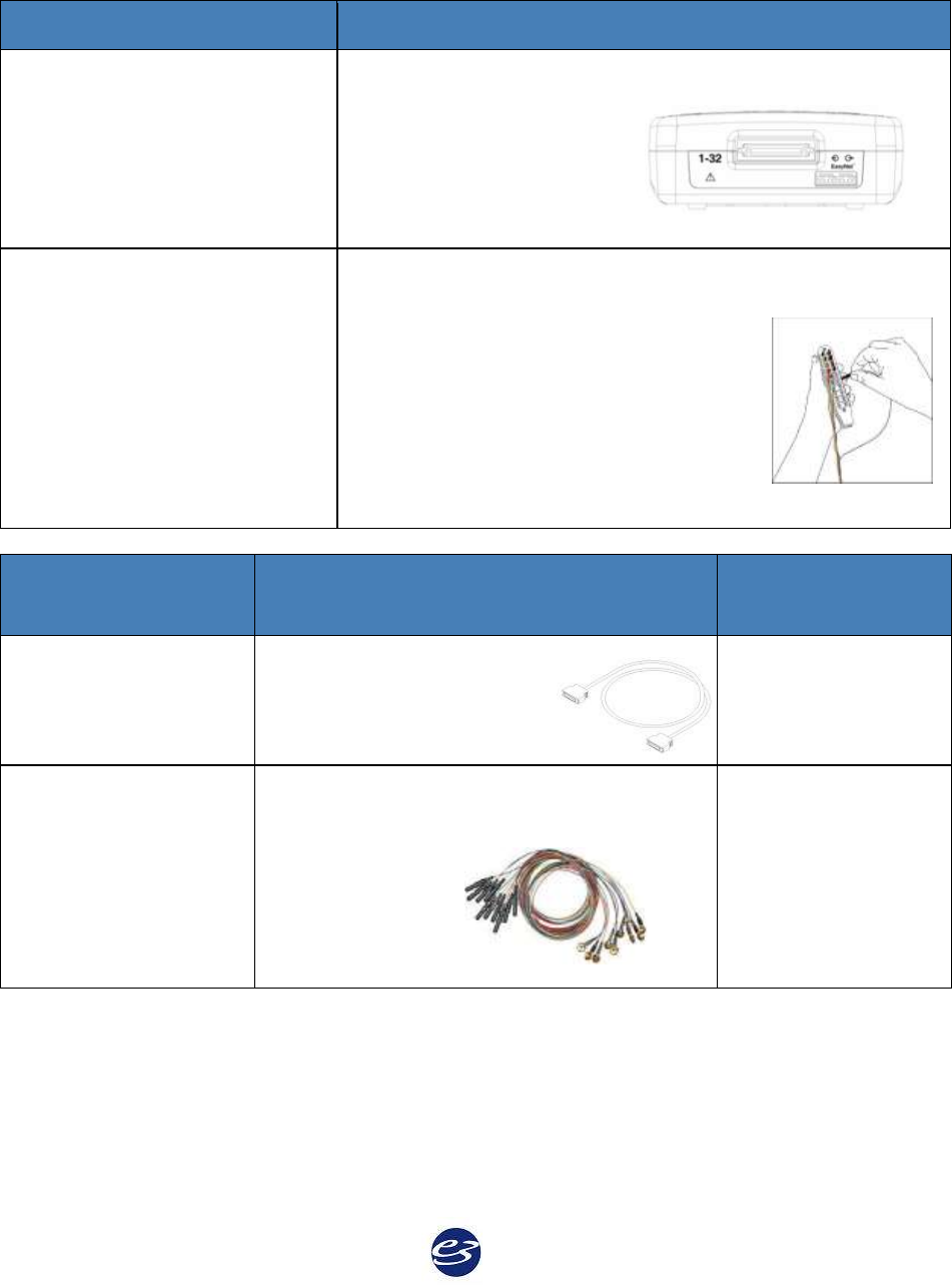
Cadwell Easy III – Version 3.5
60
Remote Input Boxes Connectors and Cables
Remote Input Box Connectors
Description
Cable Connection
Connects to the Remote Input Box Cable for data feed.
The Cable then plugs into
the input labeled 1-32 on
the side of the Amplifier.
Electrode Ports
EEG electrodes can be plugged into the inputs on the top of
the amplifier or into a remote input box. The input
connectors are designed for 0.059 inch
(1.5mm) diameter molded safety
connectors. One grounding electrode
connector is available on the side-input
box, and two ISO ground electrode
ports are available on the top-panel
box.
Remote Input
Cables
Description
Length
Remote Input Box
Cable
Connects the remote
input box to the Easy III
Amplifier.
9.8 feet (3 meters)
EEG Electrodes
Plugged into the remote input box,
electrode input connectors are designed for
0.059 inch
(1.5mm)
diameter
molded safety
connectors.
Lengths vary
61
Remote Input Boxes Warnings & Precautions
Do not immerse remote input boxes
in liquid.
Cleaning instructions in this manual
need to be strictly adhered to.
No user-serviceable parts inside.
Service by Cadwell Laboratories, Inc.
and other authorized bodies only.
The system is not designed to operate
in an explosive environment.
Inspect cables before and after each
use. Discard cable if insulation is
damaged or if the cable or connectors
are damaged in any manner.
Use only Cadwell-approved cables for
connecting your Cadwell Easy III
hardware components.
The system is not defibrillator proof.
The system is designed to be used with
one patient at a time.
Do not use the system in an MRI environment.
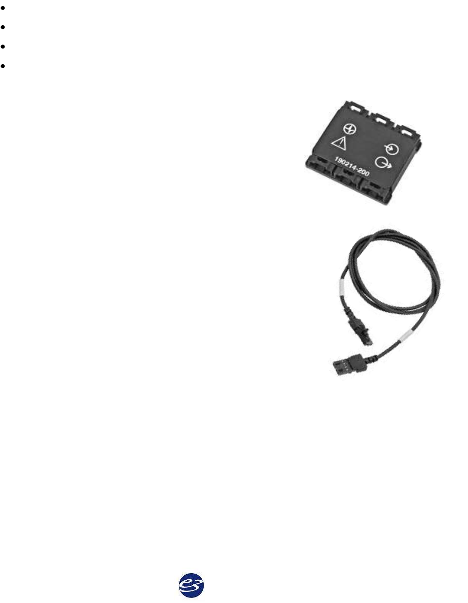
Cadwell Easy III – Version 3.5
62
Easy III EasyNet Modules*
*For use with Easy III and Easy Ambulatory amplifiers only.
EasyNet Modules are plug-and-play devices that can be configured to collect up to 12 channels
such as body position, limb movements, and SpO2 data concurrently with other PSG or EEG
channels. The following EasyNet modules can be centrally connected to the EasyNet hub:
SpO2 Module
Body Position Module
Limb Movement Module
Nasal Pressure Airflow Module
EasyNet Modules are plug-and-play devices that can be configured to collect up to 12 channels
such as body position, limb movements, and SpO2 data
concurrently with EEG data.
EasyNet Hub
The six-port EasyNet Hub (# 190214-200) may be secured within a
chest belt with its Velcro backing, providing a central connection
port for EasyNet Modules on the patient.
EasyNet Cables and Connections
EasyNet cables can connect either to the hub itself, or daisy-chain to each
other. Each module has two cable ports; one for connection, and one for
daisy-chaining module to module. EasyNet cables are available in five, 10,
20, 35, 40, 70, 96 and 180-inch lengths.
Limb movement modules are placed on the wrists and legs of the patient.
The SpO2 module is placed on the wrist or chest belt. All modules plug
into the EasyNet Hub. The EasyNet Hub can be connected to the
EasyNet input connector on the side of the Easy III amplifier. EasyNet
cables are available in multiple lengths from 3 inches to 15 feet in length.
Connecting EasyNet Cables to EasyNet Hub or Module
Insert the cable end into the cable port on the hub or any module. Push gently until the
connection ‘clicks’.
Remove EasyNet Cable from EasyNet Hub or Module
Push down on the cable lever to release the cable lock. Push the cable connection down from the
lever, and then pull gently to release.
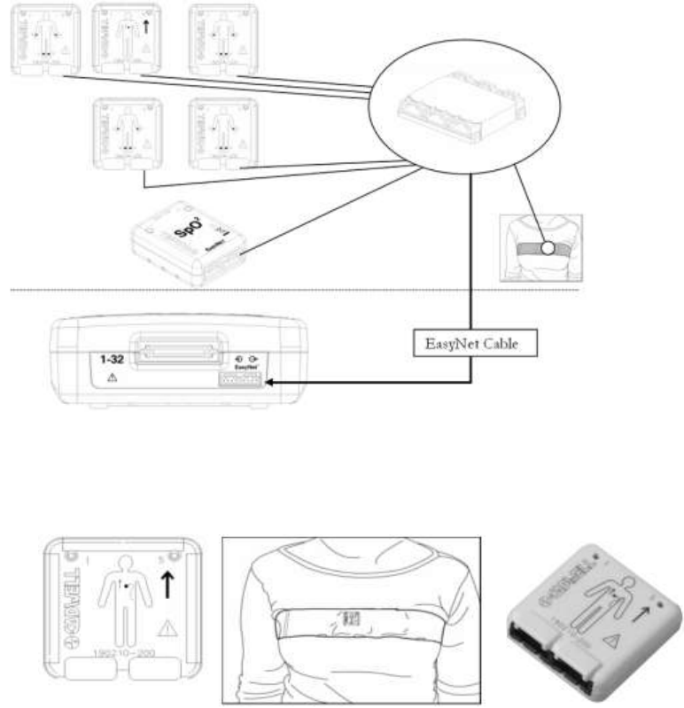
63
EasyNet Hub to EasyNet Module Connections
EasyNet Modules
Body Position Module
The Body Position Module is designed to detect Left Position, Right Position, Prone Position,
Supine Position and the Upright Position.
The Body Position Module has Velcro on the back side of the module. The sensor is placed inside
a chest belt worn by the patient. This module can be used to detect body position during an EEG,
PSG, or LTM recording.
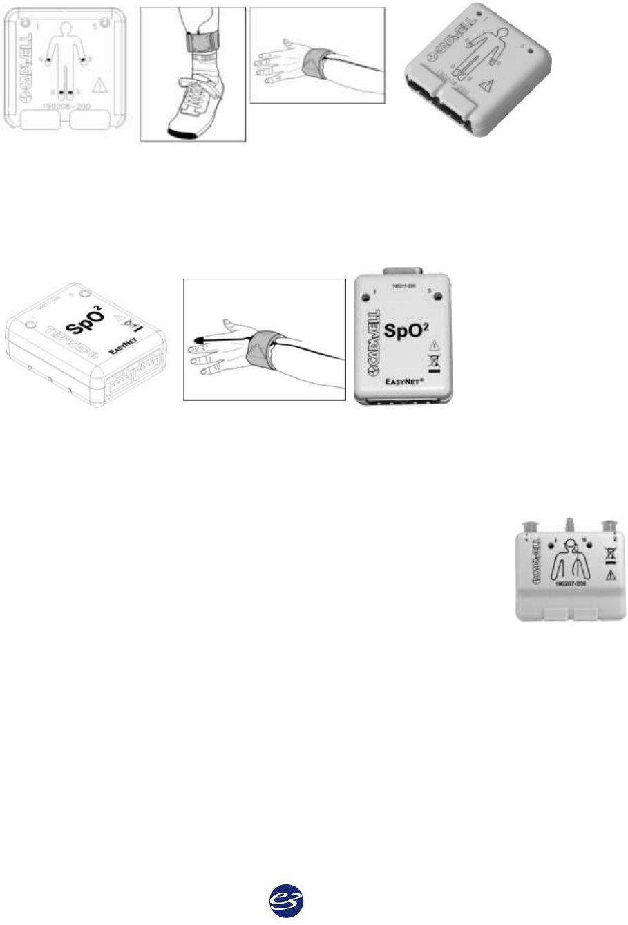
Cadwell Easy III – Version 3.5
64
Limb Movement Module
The Limb Movement module is designed to detect limb movements. The Limb Movement
modules are placed in Velcro straps worn on the wrists and ankles. These modules can be used
for EEG, PSG, and LTM recordings.
SpO2 Module
The EasyNet SpO2 Module is an oximeter that is designed to be worn on the wrist or chest belt.
This module may be configured to collect two channels: SpO2 signal (pulse) and pulse rate.
Nasal Pressure Module
The EasyNet Nasal Pressure Module is designed to record up to four
channels: nasal flow, oral flow, nasal snoring and oral snoring. The module
uses a 2-channel cannula that captures pressure changes recorded at the nose
and mouth.
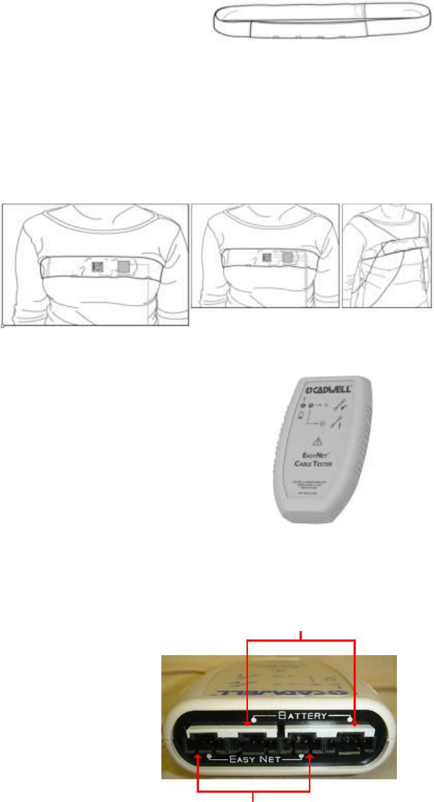
65
EasyNet Chest Belt
The chest belt is designed to hold the Body Position and EasyNet
Hub in a small pocket located on the front of the chest belt.
Place the Chest Belt on the Patient
Place the chest strap on the patient. Center the small envelope/pocket on the front of the chest.
Insert the Body Position Module and the EasyNet Hub inside the pocket on the chest strap. The
arrow on the front of the Body Position Module should be pointing up. Connect a short EasyNet
cable from the Body Position Module to the EasyNet Hub. You can use any connector on the
Body Position Module and Hub.
Place the Limb Straps on the
patient. Connect each module to
the hub in the Chest Belt. When
setting up your patients, route
the cables through the chest strap
to each limb movement module.
EasyNet Cable Tester
The EasyNet Cable Tester allows you to check the integrity of EasyNet
module and Ambulatory battery cables.
Testing EasyNet Cables
Test one cable at a time. Connect both ends of an EasyNet or Ambulatory
battery cables into its corresponding ports on the EasyNet Cable Tester.
Both green and yellow LEDs will illuminate.
The cable is good if the green LED stays lit, and the yellow LED turns off.
The cable is not good if the green and yellow LEDs remain lit. Please dispose of the EasyNet Cable
and replace it with a good one.
Battery Cable
Replace EasyNet Cable Tester AA Batteries
If the green LED on the EasyNet Cable Tester does not
illuminate when a cable is connected for testing, replace
the Tester batteries. Use the thumb grip on the battery
panel on the back of the Cable Tester to open the battery
compartment. Remove the batteries, and replace them
with two (2) AA batteries. Replace the cover, and check to
make sure the Tester works by testing a cable. If the green
LED illuminates, the Tester batteries are good.
EasyNet Cable
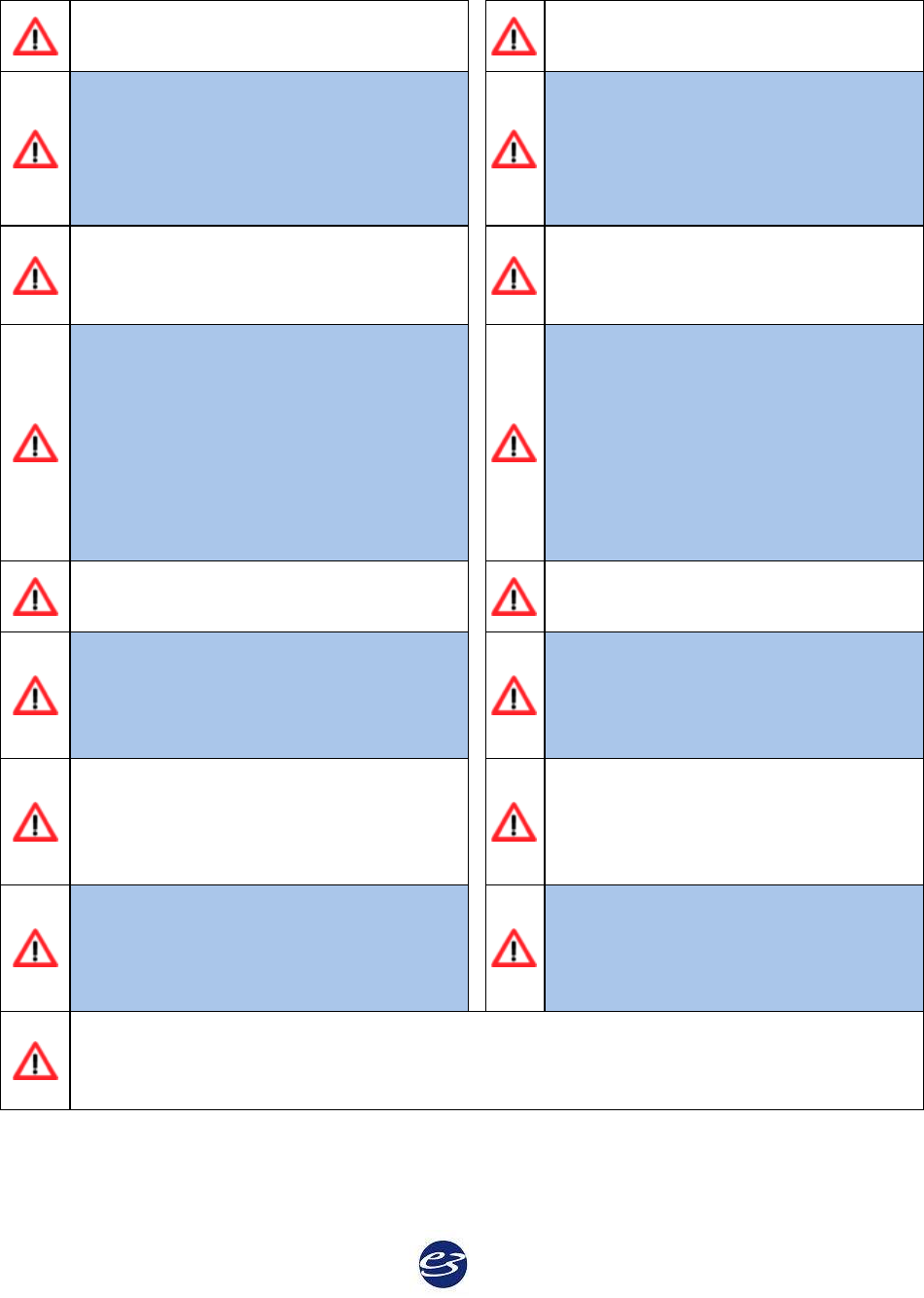
Cadwell Easy III – Version 3.5
66
EasyNet Modules Warnings & and Precautions
Federal law restricts sale of this system
to, or on the order of, a physician.
The system is not defibrillator proof.
High levels of static discharge can cause
a momentary pause in data collection.
The operator must be trained to be able
to recognize the difference between
signal artifact and valid bio-signals
caused by movements, interference, or
misplacement of sensors or electrodes.
No user-serviceable parts inside. Service
by Cadwell Laboratories, Inc. and other
authorized bodies only.
Cleaning instructions in this manual
need to be strictly adhered to.
Do not immerse the amplifier, recorder,
or modules in liquid. Do not attempt to
use the system and its modules if it has
been immersed in liquid. The system is
not water resistant or splash proof.
Avoid contact of liquids with the
internal parts and connectors of the
Cadwell Easy system.
Check the oximeter sensor application
site frequently to determine the
circulation, positioning, and skin
sensitivity of the patient. Each patient’s
sensitivity to sensors may vary
depending on their medical status or
condition of their skin.
The system is not designed to operate in
an explosive environment.
Do not attempt to use the Easy system
in an MRI environment.
Do not use a broken body position
module, SpO2, nasal pressure, or limb
movement module if the case or
connectors are cracked or broken.
Do not autoclave EasyNet modules.
Inspect EasyNet cables before and after
each use. Discard cable if insulation is
damaged or if the cable is damaged in
any manner.
Discontinue using any module or sensor
if the patient exhibits any allergic
reactions to adhesive or materials.
When using the body position and limb
movement modules, verify that they
have been placed in a Cadwell
authorized pouch, belt, or holder.
When applying tape for the oximeter
sensor, do not stretch the adhesive tape.
This may cause inaccurate readings or
skin blisters.
When attaching the Easy system to a recording subject, verify that the subject will not
become entangled in the wires. Do not allow the electrode wires to wrap around the
subject’s neck.

67
Minimum Computer Hardware Requirements
Application
Listed below are the minimum requirements for a computer to operate Cadwell Easy III.
Regulatory Requirements
Domestic (U.S. and Canada) computers: third-party certified to UL 1950 or IEC 950.
European Union computers: third-party certified to EN 60950.
Minimum Computer Hardware Requirements
Operating System
Windows XP Professional (SP2)
Processor
Dual Core, 2.13 GHz Recommend Dual Core, 3.1 GHz
Hard Disk Drive
160 GB, NTFS file system, (Recommend 750 GB if the system
is used for long term epilepsy monitoring or if several weeks
of data storage is required.)
Memory (RAM)
2 GB. (Recommend 3 GB.)
Archive Device
Recordable DVD+R/+RW and CD-RW Drive.
USB
USB 2.0 (2 port minimum)
Graphics
1600 x 1200, 256 MB, optional dual monitor output
Network Card
10 Base-T Ethernet card required for connection to amplifier.
A second network card is required for connection to a LAN,
or IP based camera.
*Computer requirements are subject to change. Always contact Cadwell prior to purchasing computer hardware for your facility.
Qualified Computer Platforms
Dell OptiPlex 755 (small form
factor configuration) *
Core 2 Duo, 2.33 GHz, 2 GB RAM, 160 GB Hard Drive,
Windows XP Pro (SP2), NTFS file system, Dual monitor-256
MB graphics card, additional low profile network card.
Dell Precision T3400*
Core 2 Duo, 2.33 GHz, 4 GB RAM, 750 GB Hard Drive,
Windows XP Pro (SP2), NTFS file system, Dual monitor-256
MB graphics card, additional network card.
Dell Latitude D830 Laptop *
Core 2 Duo, T7500 2.20 GHz, 2 GB RAM, 120 GB Hard Drive,
Windows XP Pro (SP2), NTFS file system, 15.4" display at
1680 x 1050.
Toshiba Tecra A9 *
Core 2 Duo, T7300 2 GHz, 2 GB RAM, 120 GB Hard Drive,
Windows XP Pro (SP2), 15.4" display at 1680 x 1050.
*Computer specifications and requirements are subject to change. Always contact Cadwell prior to purchasing computer hardware for your facility.

Cadwell Easy III – Version 3.5
68
Additional Software Requirements
Report Generator
MS Word 2003
Belkin Video to USB
Software
Belkin Video to USB adapter software is required if Easy III Q-
Video software is used.
Sony IPELA Software
Sony IPELA Network Driver is required when the IPELA camera
is used.
Server Installation
Validated on Server 2003, SP2 Standard Edition X Number Users
Client
Misc. Support Requirements
Remote Diagnostics
Citrix GoToAssist (internet access required)
Regulatory Requirements
Domestic (U.S. and Canada) computers must be third-party certified to UL 1950 or IEC 950.
European Union computers must be third-party certified to EN 60950.
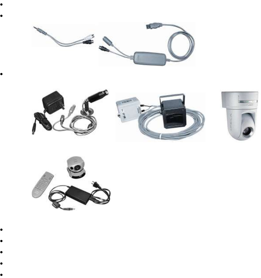
Cadwell Easy III
69
Q-Video Camera Hardware
Q-Video allows digital video to be collected concurrently with PSG or EEG recordings. The Q-
Video program captures incoming video signal and compresses the video data real time.
Q-Video Requirements
To use Q-Video, you must have:
A valid software license enabling Q-Video on your Easy III system,
A video input to your computer via a 'video to USB adapter', and
A standard video camera (NTSC/PAL) or a low-light camera for use during data collection
(The camera may be black-and-white or color, or a VCR with video output).
You may also have the optional components: sound mixer, speakers, or tilt, pan and zoom unit.
If you did not purchase Q-Video and a camera from Cadwell, you must
Purchase a licensed copy of the Q-Video software,
Install the Q-Video software,
Install camera software (follow camera software installation instructions),
Verify the camera connects to Q-Video,
Set camera for low-light input.
Cadwell Easy III – Version 3.5
70
IP Camera Setup
Sony IPELA - Model # RZ25
Before using our Sony IPELA camera, you must connect the camera to the local network. In most
configurations, the camera will be connected to a network switch shared by all Easy III systems.
The camera will be connected to the switch with an ethernet/network cable.
Assigning a IP Address to the Sony IPELA Camera
Note: The Sony factory setting of the camera is as follows: IP address: 192.168.0.100. The subnet
mask is 255.0.0.0.
1. Insert the supplied CD-ROM disc into your CD drive.
2. Click on the Setup icon of the IP Setup Program. The 'File Download" dialog will open.
3. Click Open NOTE: If you click "Save this program to disk" on the File Download dialog,
you can not install the software correctly. Delete the downloaded file, and click the Setup
icon again.
4. Install the IP Setup Program to your computer following the software wizard displayed.
If the software license agreement is displayed, read and accept the agreement to precede.
5. Start the IP Setup Program. The program will detect the Sony camera and list all Sony IP
cameras in the Network tab window.
6. Click on the camera you would like to assign an IP address.
7. To obtain the IP address automatically from a DHCP server, select 'Obtain an IP address
automatically'. The IP address, Subnet mask and Default gateway are assigned
automatically.
8. To specify the IP address manually, select 'Use the following IP address'. Type in the IP
address, Subnet mask and Default gateway.
9. To set the DNS server address automatically, select 'Obtain DNS server address
automatically.
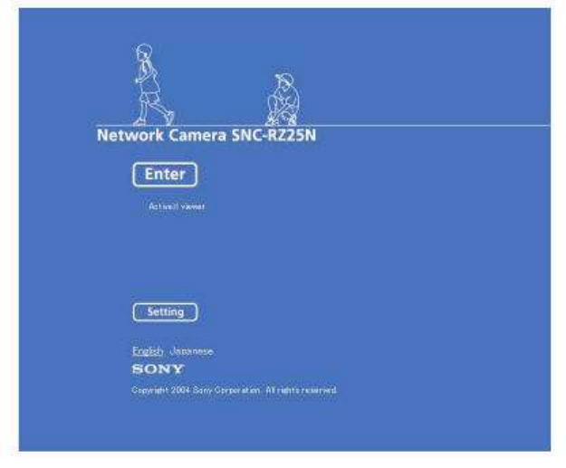
Cadwell Easy III
71
10. To specify the DNS server address, select 'Use the following DNS server address'. Enter
the Primary DNS server address and the Secondary server address. NOTE: The third and
fourth DNS address fields do not work with the Sony IPELA camera.
11. Set the HTTP port No. Normally select 80 for the HTTP port No. To use another port
number, select the text box and type a number between 1024 and 65535.
12. Type in the Administrator name and Administrator password. The default settings for
both items are "admin" NOTE: You cannot change the Administrator name and
password in this step.
13. Confirm that all items are set correctly and click OK. If 'Setting OK' is displayed, the IP
address is set correctly.
14. To access the camera directly, double click on the camera name in the camera list.
15. The following setup screen should appear after step 14.
Accessing the Sony Camera via Internet Explorer
1. Launch Internet Explorer
2. Enter the IP address of the camera in the URL box.
3. Click Enter. The main viewer will be displayed. When the camera picture is displayed
correctly, the IP assignment is complete.
4. When the main viewer is displayed for the first time, a security warning will be
displayed. Click on OK to install Active X controls.
5. NOTE: If Automatic Configuration is enabled in the LAN settings in Internet Explorer,
the camera image may not be displayed. In this case disable Automatic Configuration
and set the Proxy server manually. Consult your network administrator to set the Proxy
server.

Cadwell Easy III – Version 3.5
72
EASY III SOFTWARE
Preparing for Software Installation
Notify Bio-Med/IT dept. of Easy III install. Staff
must be on call or available during installation.
Provide internet connection to PC if possible
(Cadwell can remotely connect to PC if
necessary)
Installation will require administrative
privileges from operating system.
Workstations and server must be physically
accessible.
Provide a network receptacle if a network
connection is required.
Install and mount camera hardware if
video equipment is required.
Pull network, video, audio cable prior to
installation of software.
Verify if hospital/lab safety team must
inspect configuration and setup of Easy III
and computer hardware.
Operating System, 3rd Party Software Requirements
Installing the Easy III software requires Windows XP Service Pack 2 (or later) and Microsoft Word.
Easy III software is not compatible with Windows 98. Easy III requires Windows XP Pro, Service
Pack 2. Easy III requires Flash 9.1. QuickMed and Easy III must be installed by a user with
administrator rights (however, administrator rights are now required after the installation of
software).
The Easy III installer will verify that Windows SP2 and Flash 9.1 are installed. Connect the PC to the
Microsoft website or install Windows SP2 if necessary. If an earlier version of Flash is installed on
the local PC, the Easy III installer will upgrade the Flash software to Version 9.1.
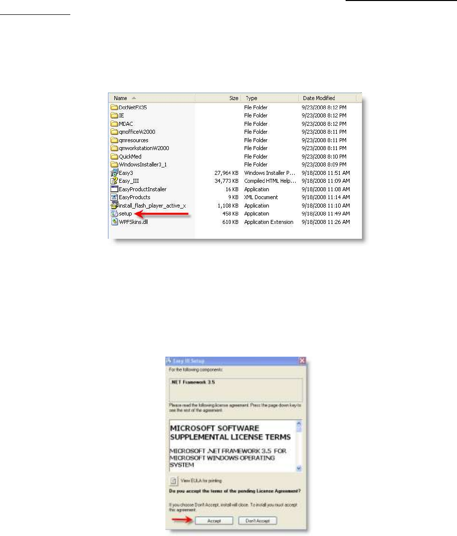
Cadwell Easy III
73
Installing Easy III Software
From an install CD: Step 1 - Installing QuickMed Office
The office server should be set up before any of the other Easy III systems. Only one office server is
needed per site. If you have already installed the Office Server on another system, skip this section
and proceed to Step 2, Installing QuickMed Workstation.
Step 1 - Installing QuickMed Office
1. Click on the setup.exe from the Easy III folder on the installation disc.
2. If the version of Microsoft .NET Framework is out of date, the installer will prompt you to
install a new version of .NET. If you are presented with the menu displayed below, click on
Accept. The Easy III installer will install the .NET Framework software. Note: The
installation of the .NET Framework software may take several minutes. After installation is
complete, reboot if prompted to do so. After rebooting, the Easy III installation will
automatically continue.

Cadwell Easy III – Version 3.5
74
3. You will be prompted with the message below. Click Yes.
4. The Install Utility will be displayed. Note the picture displayed below. Enter the default
Clinic ID is IHS35NYV25ZY4833D.
5. Enter the default Product Key is 1Z0OSEHY. Note: Do not enter the Product Key if the system
you are installing is not the Office Server system used in your facility. Only one system can be
configured as an Office Server system.
6. After entering the Product Key, select the ‚QuickMed – Office‛ option, then click ‚Install‛.
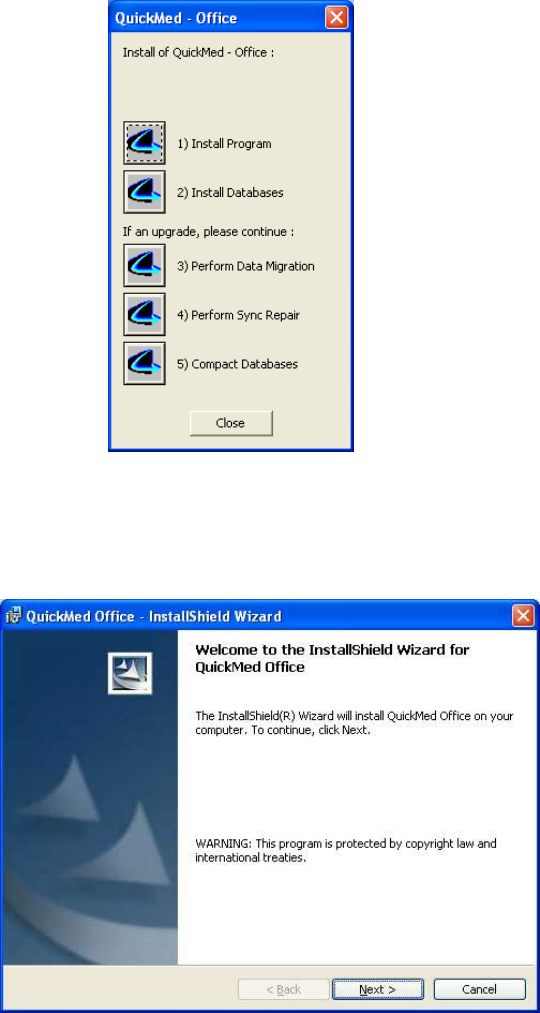
Cadwell Easy III
75
7. The QuickMed Office installation panel will be displayed. Click the ‚Install Program‛
button to start up the QuickMed Office installation wizard.
8. Step through the wizard clicking ‚Next‛ on each page. Do Not Change the Destination
Folder when installing QuickMed Office. Install the software in the default destination
(C:\Cadwell\Easy III).
9. On the last page of the wizard, click ‚Install‛ and wait for the install to complete, then click
‚Finish‛. You should now see the following options displayed in the QuickMed installation
panel:

Cadwell Easy III – Version 3.5
76
10. Click the ‚Install Databases‛ button. Once the databases are finished installing, click the
‚Close‛ button. Note: If you’ve previously installed QuickMed Office, you may see an error
message about databases already existing. This is expected. Simply dismiss that error
dialog. AT THIS POINT, DO NOT REBOOT THE COMPUTER, EVEN IF PROMPTED TO
DO SO
11. You should now be back at the Install Utility dialog. Leave the Install Utility menu open;
proceed to the next section for information on installing the QuickMed Workstation.

Cadwell Easy III
77
Optional: Setting up the Office Server as a Service:
This configuration allows the Office Server to run in the background without having a specific
user logged into the system. To configure the Office Server to run as a service, follow the
instructions below.
1. Select and copy all 4 batch files located in the Office Server Service folder on the
installation DVD.
InstallService
UninstallService,
XYNTService, and
XYNTService.
2. Paste all 4 files into C:\Cadwell\Easy III
3. Double click on Install Service. A dialogue box will flash quickly on the screen and go
away.
4. Reboot the server.
5. When server starts up make sure that QMAssistant and RPOfficeserver do not start up,
the icons should not show up in the bottom right task tray.
6. Check in Task Manager that the applications are running.
7. Verify that the computers networked to the server and running Easy III are synching
appropriately by opening the QMAssistant. The dialogue should say Connected to Office
Server.

Cadwell Easy III – Version 3.5
78
Step 2 - Installing QuickMed Workstation
1. Select the ‚QuickMed – Workstation‛ option and click the ‚Install‛ button.
2. Select or type the name of your office server machine in the ‚Office Server Name‛ combo
box. If the machine you’re installing on is also the office server or you don’t have an office
server on your network, don’t change the default value. If you don’t have an office server on
your network and the box is empty, type your computer name. If you are unsure what
Office Server name to enter, Call Cadwell for assistance.
3. Click the ‚Install Program‛ button to start up the QuickMed Workstation installation
wizard.
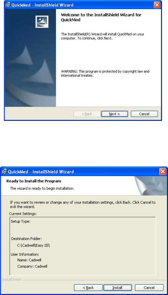
Cadwell Easy III
79
4. Step through the wizard clicking ‚Next‛ on each page. Do Not Change the Destination
Folder when installing QuickMed Workstation. Install the software in the default
destination (C:\Cadwell\Easy III).
5. On the last page of the wizard, click ‚Install‛ and wait for the installation to complete, and
then click ‚Finish‛.

Cadwell Easy III – Version 3.5
80
6. You should now see the following options:
7. Next, click the ‚Install Databases‛ button to install the QuickMed Workstation database.
Note: If you’ve previously installed QuickMed Workstation, you may see an error message about
databases already existing. This is expected. Simply dismiss that error dialog. Once the database
are finished copying, click the ‚Close‛ button on the above dialog. AT THIS POINT, DO
NOT REBOOT THE MACHINE EVEN IF PROMPTED TO DO SO.
8. You should now be at the ‚Install Utility‛ dialog. Click the ‚Exit‛ button.
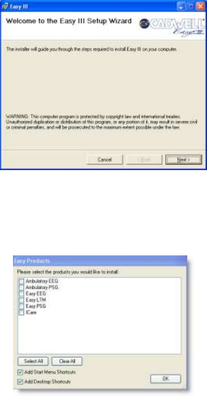
Cadwell Easy III
81
Step 3– Installing Easy III Software
1. Launch the setup.exe (again) from the Easy III folder on the installation disc. You should
now see the following dialog:
2. Step through the Easy III installation wizard by clicking ‚Next‛ on each of the pages. When
the installation is complete you will see the following dialog:
3. You will be prompted to select the Easy Products you would like to install. Select the
products you have purchased. Click on the OK button.

Cadwell Easy III – Version 3.5
82
4. Click ‚Close‛ to complete the installation. At this point, you will be asked to restart you
machine. Please do so.
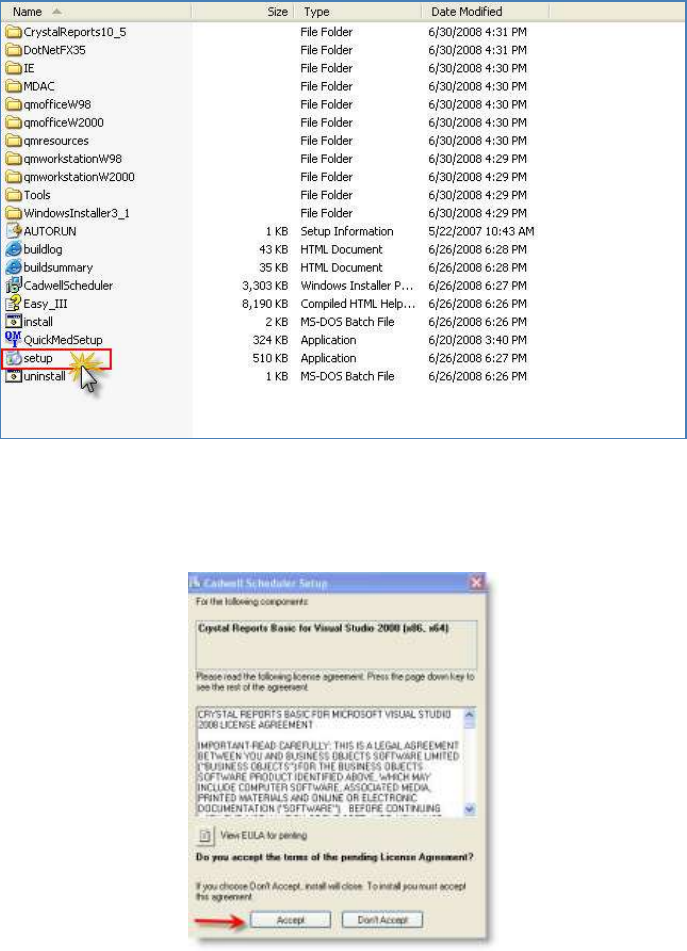
Cadwell Easy III
83
Step 4 - Installing the Cadwell Scheduler
The Easy Scheduler should be installed after the Office Server system or the Workstation system
has been configured with Easy III software. The Easy Scheduler can be installed on a separate
computer system without installing the Easy III client.
1. Click on the Setup program in the Scheduler installation folder.
2. The installer will install Crystal Reports for Visual Studio 2008 (x86, x64) if it is not present
on your system. Click on the Accept button to install the Crystal Reports. Note: The
Cadwell Scheduler Setup program will install Crystal Reports. This may take several
minutes.
3. Click on Next to install the Scheduler program on your computer.
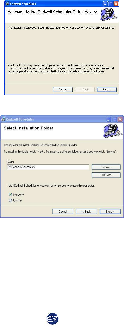
Cadwell Easy III – Version 3.5
84
4. Select the default folder. The folder must be C:\Cadwell\Scheduler\
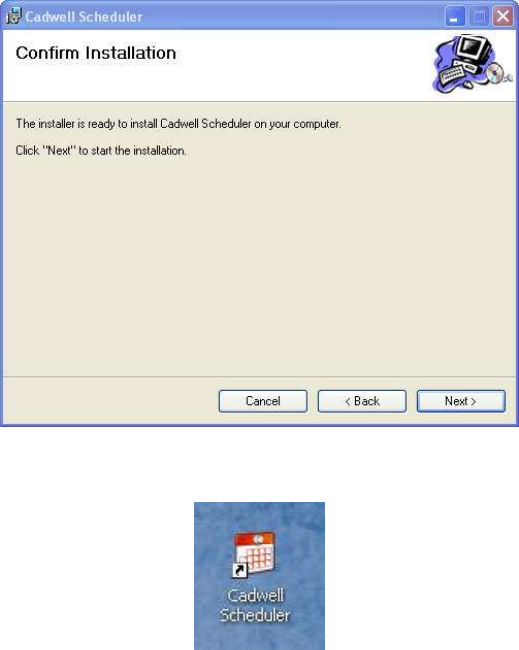
Cadwell Easy III
85
5. Click on Next to install the Scheduler.
6. You will be prompted with the Installation Complete dialog. Click on Close to exit.
7. To access the scheduler you can click on the desktop shortcut.
8. The scheduler can also be opened by clicking on the shortcut displayed in Easy III.
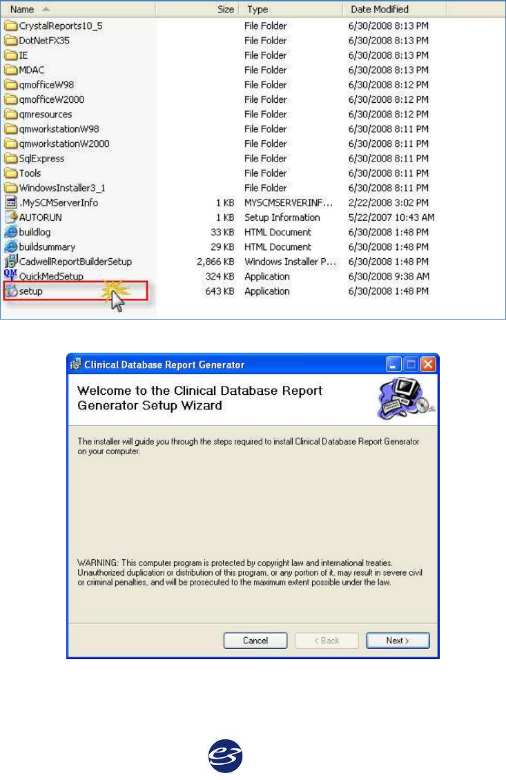
Cadwell Easy III – Version 3.5
86
Step 5 - Installing the Cadwell Clinical Database
The Cadwell Clinical Database should be installed after the Easy III software has been installed.
1. Click on the setup.exe file in the Clinical Database installation folder.
2. Click on Next to continue.
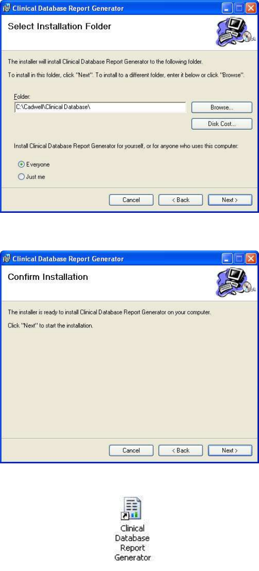
Cadwell Easy III
87
3. Click on Next to confirm the installation of the Clinical Database Report Generator. Do not
change the default folder location.
4. Proceed through the installation. When the installation is complete, click on the Close
button.
5. Click on the Clinical Database shortcut on your desktop to access the database.
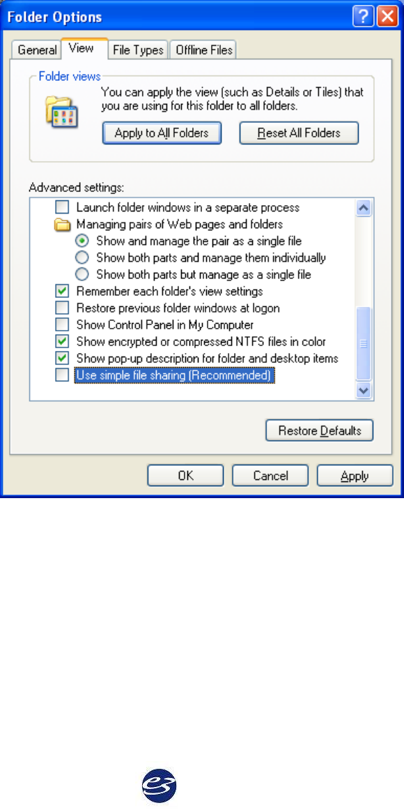
Cadwell Easy III – Version 3.5
88
Step 6 – Setting up File Sharing (required for all systems)
1. In Windows Explorer, move to the ‚C:\‛ directory.
2. Click the ‚Tools‛ menu in Windows Explorer and select the ‚Folder Options…‛ menu item.
Select the ‚View‛ tab and scroll to the bottom of the list. Uncheck the ‚Use simple file
sharing‛ checkbox as shown here:
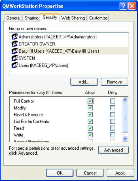
Cadwell Easy III
89
3. Click ‚OK‛ to dismiss this dialog. Right-click on the ‚C:\QMWorkstation‛ directory and
select the ‚Properties‛ menu item, then select the ‚Security‛ tab to get the following dialog:
4. If the desired group (for example, ‚Everyone‛, ‚Power Users‛, ‚Easy III Users‛) is not in the
list, select the ‚Add…‛ button, select (or type) the desired group and click ‚OK‛. Now, for
the desired group, click the ‚Allow‛ ‚Full Control‛ check box and click ‚OK‛.
5. Allow Easy III Access: Repeat step 4.3, but replace the directory that we are giving rights to
from ‚C:\QMWorkstation‛ to ‚C:\Cadwell\Easy III‛.
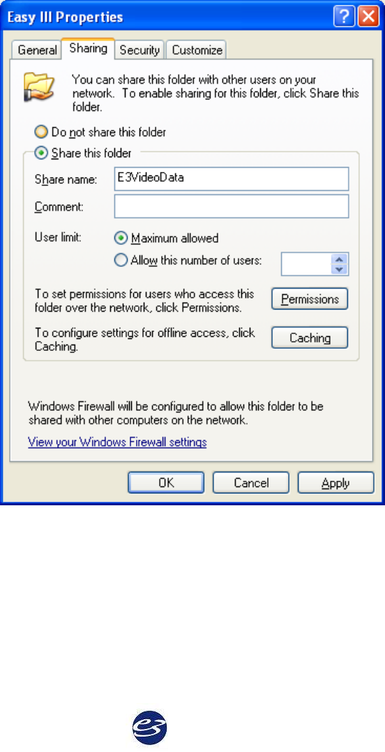
Cadwell Easy III – Version 3.5
90
Making video and data available to other client computers
All data files and video files are written to ‚C:\Cadwell\Easy III\Data‛ In order for a
remote machine to view a record remotely, the recording system must have the
‚C:\Cadwell\Easy III\Data‛ folder shared as ‚E3VideoData‛.
a. In Windows Explorer, go to ‚C:\Cadwell\Easy III‛.
b. Right-click on the ‚Data‛ folder and select ‚Properties‛
c. Select the ‚Sharing‛ tab and select the ‚Share this folder‛ radio button.
d. Type ‚E3VideoData‛ for the share name as seen below.
e. Click the ‚Permissions‛ button.
f. If the desired group or user (for example, ‚Power Users‛, ‚Easy III Users‛) is not in
the list, select the ‚Add…‛ button, select (or type) the desired group or user and
click ‚OK‛. Now, for the desired group, click the ‚Allow‛ ‚Full Control‛ check box
and click ‚OK‛.
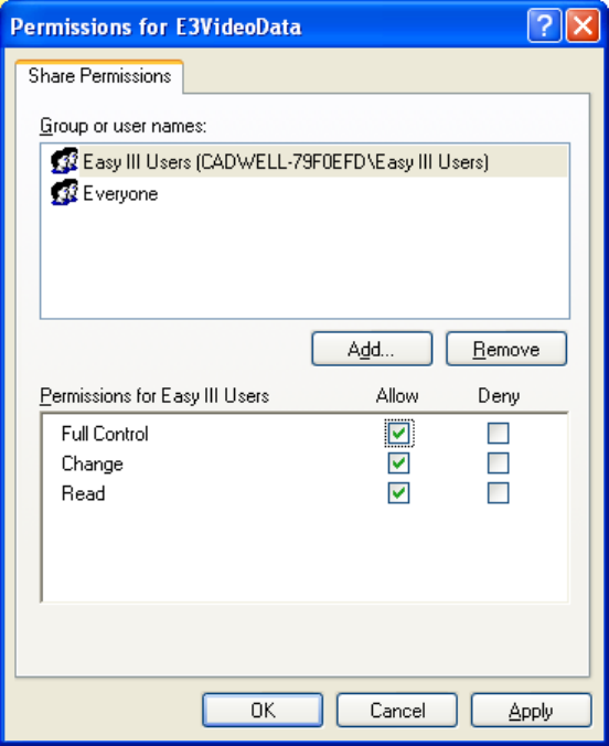
Cadwell Easy III
91
g. Now, select the ‚Security‛ tab.
h. If the desired group or user (for example, ‚Power Users‛, ‚Easy III Users‛) is not in
the list, select the ‚Add…‛ button, select (or type) the desired group or user and
click ‚OK‛. Now, for the desired group, click the ‚Allow‛ ‚Full Control‛ check box
and click ‚OK‛.
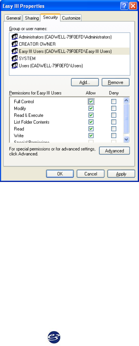
Cadwell Easy III – Version 3.5
92
NOTE: This all assumes that the hosting and remote viewing machines are on a network where they
are visible to one another.

Cadwell Easy III
93
Configure the Network Card
Easy III communicates with the PC over an Ethernet link. A dedicated Ethernet network card
must be installed in the PC, and the card must be configured to a specific IP address to
communicate correctly. Connecting to a local area network will require a second network card. To
configure the IP address in a Windows XP operating system:
1. If necessary, install a network card in the computer. Follow the network card's
manufacturer's instructions.
2. Login as a user with administrative rights.
3. From the Windows desktop, open the Start menu.
a. Open the Control Panel and open Network and Internet Connections.
b. Click on Network Connections. A separate icon for each network card installed will
be displayed. By default, each is named "Local Area Connection."
c. Rename the network card used to connect to the Easy III hardware. Do so by right-
clicking on the icon and select Rename, then typing a new name, such as "Easy III".
4. Right-click over the renamed network connection icon.
a. Remove checkmarks next to everything except Internet Protocol (TCP/IP).
b. If desired, checkmark the "Show icon in notification area when connected" to enable
a pop-up message in the system tray showing when the connection to the Easy III
system has been made.
5. Click the Configure button.
a. Under the Advanced tab, select your link speed or media type, and change the value
to 10mbs Full Duplex.
b. Under the Power Management tab, remove checkmark next to "Allow computer to
turn off this device to save power."
c. Click the OK button.
6. Return to the Properties window.
7. Click on Internet Protocol (TCP/IP) so it is highlighted.
8. Click the Properties button.
a. Select "Use the following IP address".
b. Enter IP address: 192.168.113.166 and Subnet mask: 255.255.255.0.
c. Click the Advanced button and open the WINS tab.
d. Remove the checkmark next to "Enable LMHosts lookup".
e. Checkmark "Disable NetBIOS over TCP/IP".
f. Click the OK button.
9. Click the OK button and then click the Close button.

Cadwell Easy III – Version 3.5
94
Activate Software Licenses
Easy III software features require a software key for:
EEG data collection
EEG data reader
PSG data collection and
review
PSG data reader
Video data collection
Video review only
Video review and editing
Archiving capabilities
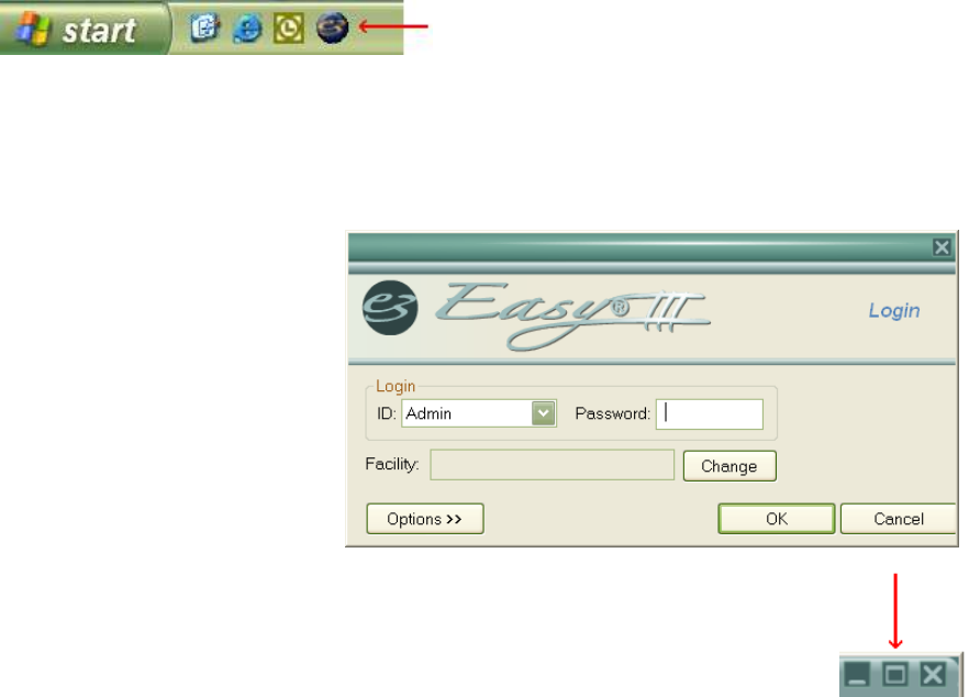
Cadwell Easy III
95
Software Overview
Open Easy III Software
1. Launch the Easy III software:
Click on the Easy III desktop icon.
or
Open the Start menu, select All Programs, select Cadwell, select Easy III and select Easy
III.
or
Select Easy III from the Quick Launch taskbar.
To add Easy III to the Quick Launch menu, right-click on the toolbar, select Toolbars, and
make sure there is a checkmark next to Quick Launch. Right-click the toolbar again, and
make sure there is no checkmark next to Lock the Taskbar. Then click and drag the Easy III
desktop icon and drop it into the taskbar. Right-click the taskbar, and select Lock the Taskbar.
2. Log in.
Select your log in from the
drop-down menu, enter your
password and click the OK
button. The Start Page will
open. By default, your initial
password is the same as the
Login ID. See Manage Users to
change your password.
3. Maximize Start Screen display.
Click on the Window button to maximize the display. The system will default
open to a maximized screen unless it is closed while in a minimized screen.
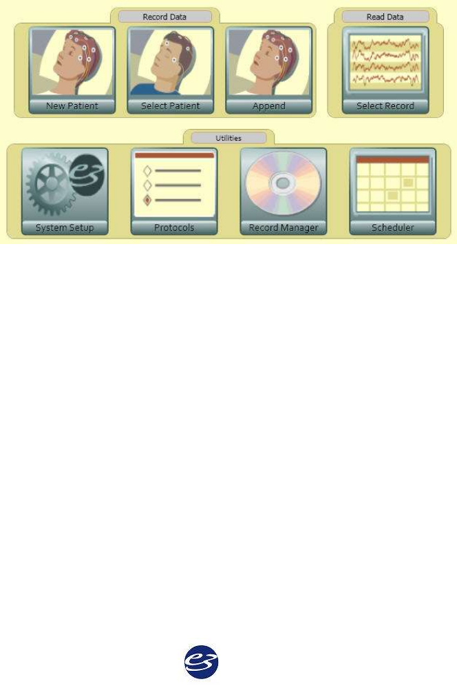
Cadwell Easy III – Version 3.5
96
Close Easy III Software
1. When finished with a procedure, press the Run button to stop recording.
2. Click the Close to exit the patient procedure, or click the top right-hand X to exit Easy III.
Start Page Overview
Start Page Options
The start page in Easy III will vary based on the specific modality you have purchased from
Cadwell. Below are some of the typical options you will find when entering the Easy III
software.
Menu Options
New Patient - Select this option to enter new patient information and start a new recording.
Select Patient - Select this option to select the name of a patient that is already in the Easy patient
database. Use this option to import patient information and start a new recording.
Append - This option can be used to add data to a previously saved data file. This option is
helpful when data collection is interrupted due to power loss. Click on this option to find the
original file, append the file, and resume data collection.
Select Record - Use this option to select a record to review and analyze.

Cadwell Easy III
97
System Setup - Select this option to:
Select Default Amplifier
Select Default Data Map
Select Default Notch Filter
Select Default Data Folder Location
Edit or Create Montages
Edit or Create Average References
Edit or Create Flash Programs
Edit or Create Data Maps
Edit Hyperventilation Scripts
Edit or Create Easy Users/Passwords
Edit or Create User Defined PSG Events
Enable/Disable AASM PSG Settings
Edit PSG Event Detection Settings
Protocols - Use this option to configure the default recording layout that will be used during data
collection. The protocol editor will allow the user to do the following:
Select the default protocol used for data collection
Modify or create the protocol used for data collection
Create data collection workspace layouts
Create default user events
Assign default reports to R1, R2, and R3 buttons
Assign default montages to M1- M6 montage buttons
Assign default paper speed, amplifier type, and calibration montage to workspace
Record Manager - User this option to Archive, Export, Copy, Move and Delete data files. The
Record Manager also has an archive database to allow the user to quickly review a list of all
studies archived.

Cadwell Easy III – Version 3.5
98
Scheduler- The Scheduler allows Easy III users to create and review appointments associated
with Easy III equipment, patient rooms, physicians, and technicians. The scheduler can be
synchronized across all systems.
Ambulatory Tools - Use this option to view ambulatory recorder status
information (battery level, memory capacity, recorder status). The user can
also start a new recording, download a recording, and clear a recorders
memory from this menu option.
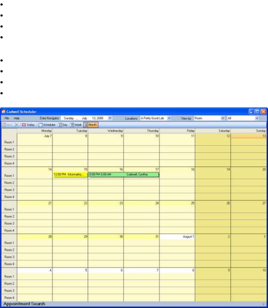
Cadwell Easy III
99
Cadwell Scheduler Options
The Cadwell Scheduler is a powerful tool that will allow Easy III users to schedule and manage
appointments. The scheduler allows the user to set up and manage schedules for multiple
locations based on the following categories:
Room Number
Physician
Technician
Equipment Type (EEG, PSG, Ambulatory recorder)
Scheduler Features
Multiple calendar views (monthly, weekly, daily)
All appointments are synchronized between all Easy III based systems.
A separate installation is supported for systems that require access to the Scheduler only.
Quick Recording Launch is supported by right-clicking on an appointment in the
calendar.
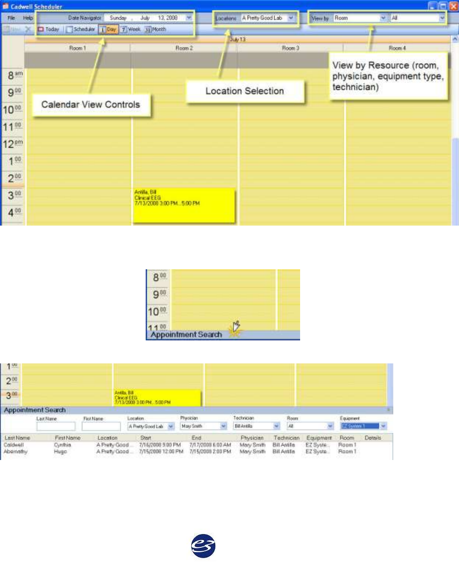
Cadwell Easy III – Version 3.5
100
Accessing the Scheduler
From the Easy III desktop, click on the Scheduler option.
The Scheduler can also be accessed by clicking on the Cadwell Scheduler shortcut from the
Windows desktop.
Note: A user name and password is required to log into the Cadwell Scheduler.
Calendar Options
Searching for an Appointment
Click on the Appointment Search bar.
The following options will appear.
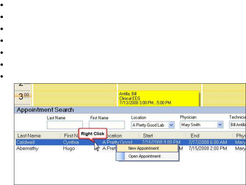
Cadwell Easy III
101
Search by Options:
Last Name
First Name
Location
Physician
Technician
Room
Equipment
Note the illustration above. When the correct patient is found, highlight the patient name, Right
Click on the highlighted name and select New Appointment or Open Appointment to proceed.
Configuring the Scheduler for Use
1. Add Facility Information. Click on File, Manage, Locations. Enter facility information.
2. Add Resource Information. Click on File, Manage, Resources. Enter room number, and
equipment information. Select physician and technician names that will be used in the Cadwell
Scheduler.
Note: You must create Easy user names and passwords for all physicians and technicians that
will be included as resources in the Cadwell Scheduler.
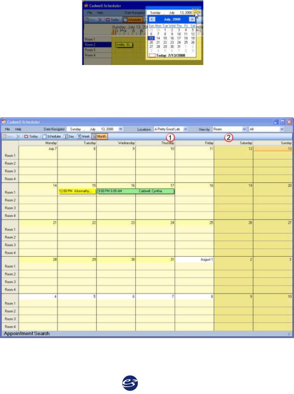
Cadwell Easy III – Version 3.5
102
Picking a Specific Date to View on the Calendar
Click on the Date Navigator to find a specific date.
Viewing the Scheduler by Resources
In the window below, note the following steps.
1. Select the Location
2. Select View by Room. The calendar will display the current calendar by room.
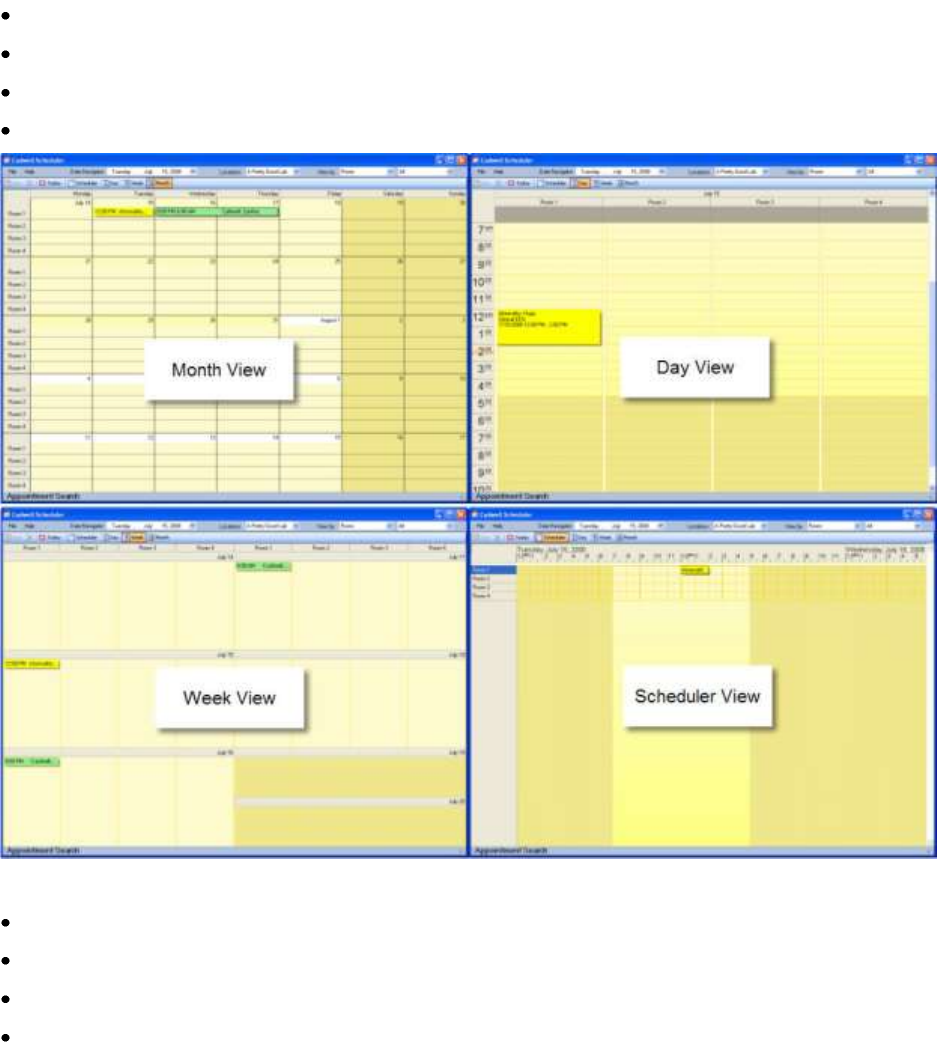
Cadwell Easy III
103
3. Multiple views are available for use. Note the illustration below, the views are filtered by
Room Number.
Month View
Day View
Week View
Scheduler View
4. Within each view, the user can select to view the calendar by:
Physician Name
Technician Name
Room Number/Name
Equipment Type
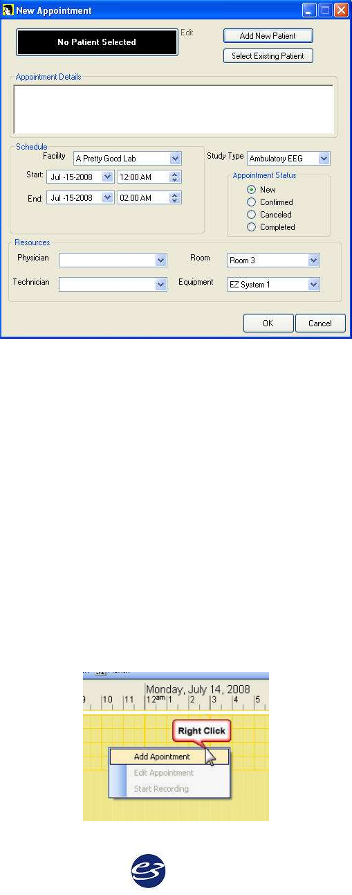
Cadwell Easy III – Version 3.5
104
Adding a Patient to the Scheduler
1. Click on 'New' or double click on a selected date in any calendar view (monthly, weekly,
daily, scheduler).
2. Click on 'Add New Patient' or 'Select an Existing Patient'. Select or enter patient details.
3. If the Scheduler is used for more than one facility, select the Facility you would like to use.
4. Select the appointment Start and End dates and times.
5. Select the Study Type.
6. Select the Appointment Status.
7. Assign the patient to the correct Resources (Physician, Technician, Room, Equipment).
8. Click on OK. The appointment will be copied to all accessible Easy III systems configured
with the Cadwell Scheduler.
Adding an Appointment from the Scheduler View
The user can add and edit an appointment by dragging across the calendar with a mouse, Right
Click on the selected time period and Left Click to Add Appointment.
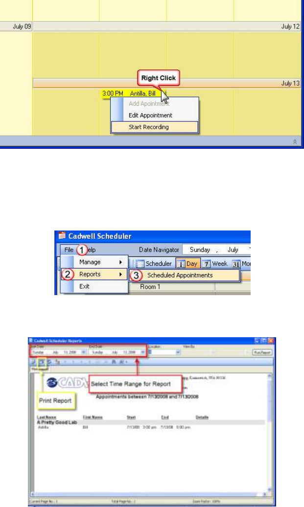
Cadwell Easy III
105
Starting a Recording from the Scheduler
To start a recording, the user right-clicks on an appointment in the calendar in any view –
monthly, daily, etc. - and selects Start Recording from the pop up menu. If the Easy program is
not already open, the Easy software will start up and a new live recording session will be started.
If the study type does not have a default protocol (PSG, EEG, etc.), the user will be prompted to
select one.
Printing a Schedule Summary Report
1. Click on File
2. Click on Report
3. Click on Scheduled Appointments
4. The Report Generator will be displayed. Select the time range for the report.
5. Click on Print Report
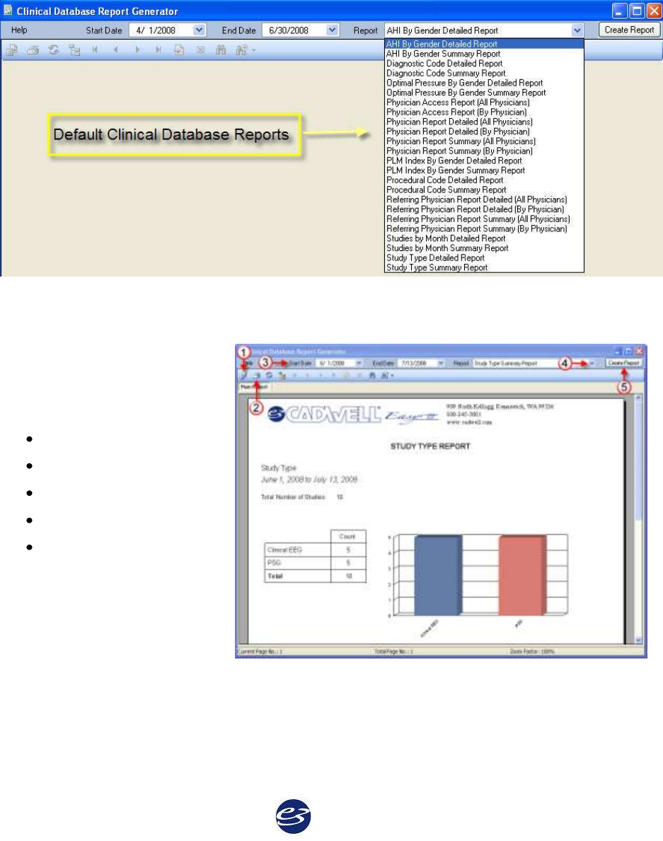
Cadwell Easy III – Version 3.5
106
Clinical Database Options
The Easy III system can be configured with a Clinical Database. The database will allow the user
to create multiple reports that summarize clinical and administrative information. Users define
the date range used with a selected report.
The following default reports are generated by Crystal Reports:
Clinical Database Options
Note the illustration.
1. Select this option to export the
displayed report. You can export
the report in the following
formats:
Crystal Reports (.rpt)
Adobe Acrobat (.pdf)
Microsoft Excel (.xls)
Microsoft Work (.doc)
Rich Text Format (.rtf)
2. Click on this option to print
the displayed report.
3. Click on this option to
determine the date range you
would like to use for the report.
4. Click on this option to select the specific report you would like to generate.
5. Click on this option after you have selected a report type. The report will be generated and
displayed in the Report Generator window.
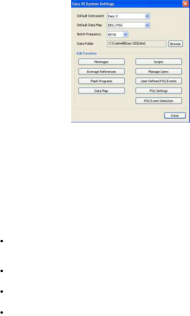
Cadwell Easy III
107
Easy III System Setting
Default Instrument -The Default Instrument may be set for use with the Easy 3, Easy II, and Easy
Ambulatory amplifiers.
Default Data Map - A specific Data Map can be selected for use with an Easy Amplifier. Default
data maps exist for EEG, PSG, and ambulatory based recordings.
Notch Frequency - The default notch frequency is 60 Hz, but may be changed to 50 Hz.
Data Folder - The data folder is the location where all data files and video files are written during
data collection. Note the illustration below.
IMPORTANT NOTES:
Cadwell recommends that this path always be set to a local drive on all Easy Systems
configured to collect/record data. If a network data folder is selected, data may be lost if
the network path is not accessible during data collection.
The Easy system can be configured to copy or move data to a network location after data
collection with the Centralized Data Manager Utility.
If you change the default data path, all files in the Easy III data folder will automatically
be moved to the new location.
If you set your data folder location to a network path, deleted files will not be saved in
the Windows Recycle Bin.
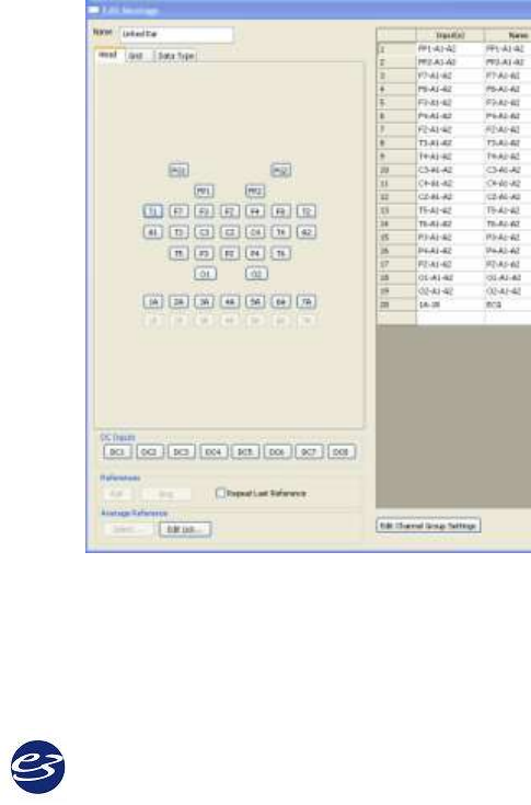
Cadwell Easy III – Version 3.5
108
Montages
Montages support an unlimited number of channels. Montage channels can be defined
from head pattern, grid electrodes, DC inputs and EasyNet devices.
Edit Montages
Montage creation or editing is controlled by user permissions. If the user has the right to
create montages, the montages will be distributed to other Easy III systems via the
synchronized database.
Add a user-defined PSG Event to a Montage/Channel.
1. Select a montage from the List.
2. Create a new montage in the Edit Montage Window (see below).
3. Edit Select a montage from the list and click the Edit button to open the Edit
Montage Window (see below).
4. Copy Select a montage from the list and click the Copy button to create a copy of
the Montage at the bottom of the list (shown above).
5. Delete Select a montage from the list and click the Delete button to remove the
montage and all of its properties.
Edit Montage Window
Name Edit or create a name for a new
montage.
Head Tab Manually build a montage
channel by channel. This tab represents
the view a technician will see from a
10-20 map; most commonly used for
EEGs.
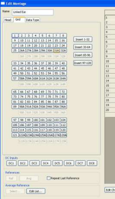
Cadwell Easy III
109
Grid Tab
Create a montage for up to four remote input boxes. This tab shows all grid inputs.
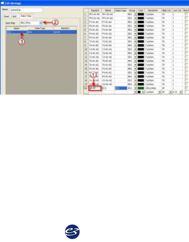
Cadwell Easy III – Version 3.5
110
Data Type Tab
Data type mapping reduces click strokes to one click per channel by assigning default
properties to each channel. Each channel in the Data Type tab has been previously
defined. All relevant settings are automatically imported when a channel is added to a
montage from the Data Type tab.
1. First Click in the Input(s) cell in the row you would like to add a new channel.
2. Verify that you are using the correct Data Map. Select a different Data Map from
the drop-down list on the Data Type tab if a different map is required. The
selected map will be the default map used with the current montage.
3. Click the name of the channel from the Data Map table to add a channel to the
displayed montage. The channel that you have selected will automatically
populate the columns with the correct settings. Note in the example below, the
EKG channel has been added to channel 20. The data type, group, sensitivity, and
filter settings do not have to be selected. These settings are previously defined in
the EEG/EKG data map.
Repeat for additional channels.
DC Inputs
Add a DC Input to a channel by clicking one of the DC1- DC8 buttons.
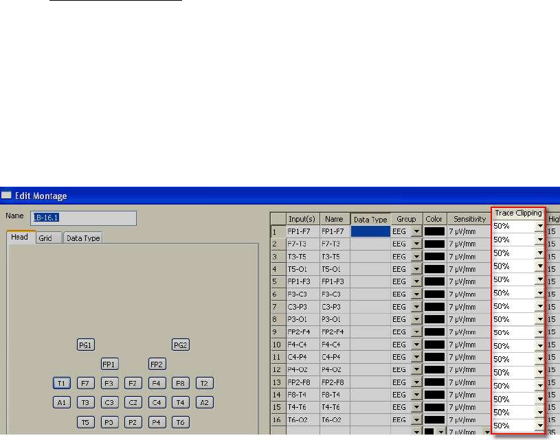
Cadwell Easy III
111
Trace Band Clipping Feature.
This option will allow the user to configure how much overlap is allowed between recorded
channels. Settings can be accessed through the montage editor or by left clicking on the
trace labels during review or data collection. Trace band overlap settings can also be
adjusted ‘on-the-fly’ by left clicking on the trace label during data collection or review.
Trace Clipping Range
No Clipping = Full amplitude range of recorded data will be displayed
0% = No clipping or overlap allowed over adjacent channels
25% = Recorded data will overlap up to 25% of adjacent channels
50% = Recorded data will overlap up to 25% of adjacent channels
100% = Recorded data will overlap up to 25% of adjacent channels
200% = Recorded data will overlap up to 25% of adjacent channels
500% = Recorded data will overlap up to 25% of adjacent channels
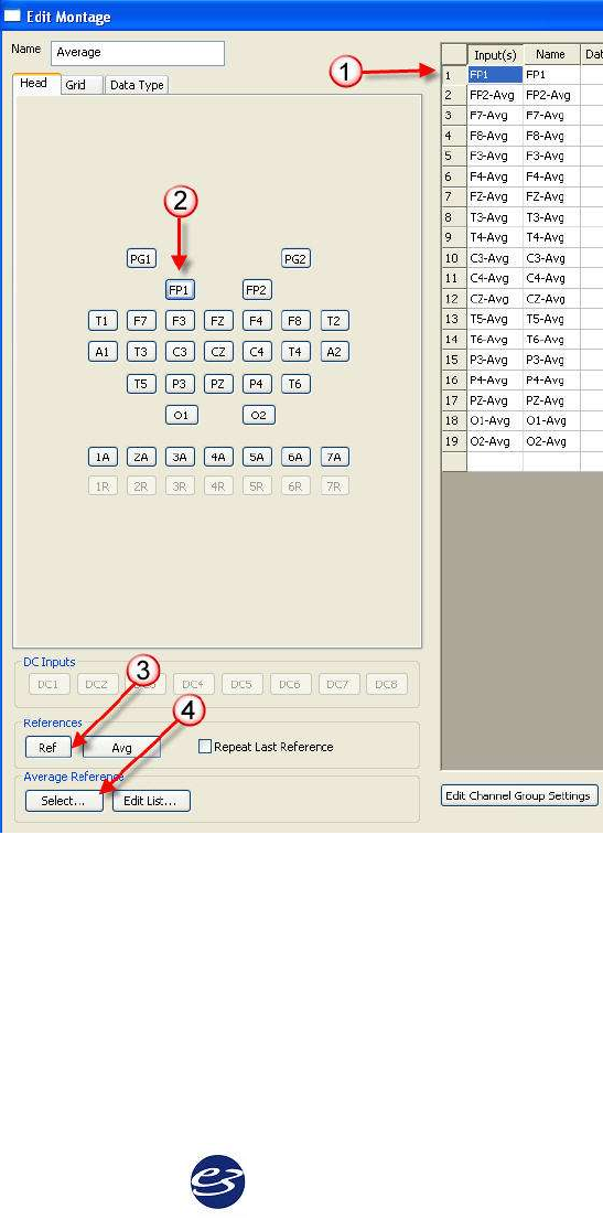
Cadwell Easy III – Version 3.5
112
Reference and Average Reference Inputs
1. Click on the Input cell for the channel you would like to edit.
2. Click on the active input you would like to use (Fp2 in the example below):
3. Select the Reference (Ref) or Average (Avg) you would like to add to the selected
channel; or,
4. to toggle the available reference configurations, click on the Select button.
Note the Avg button will change to the next available reference.
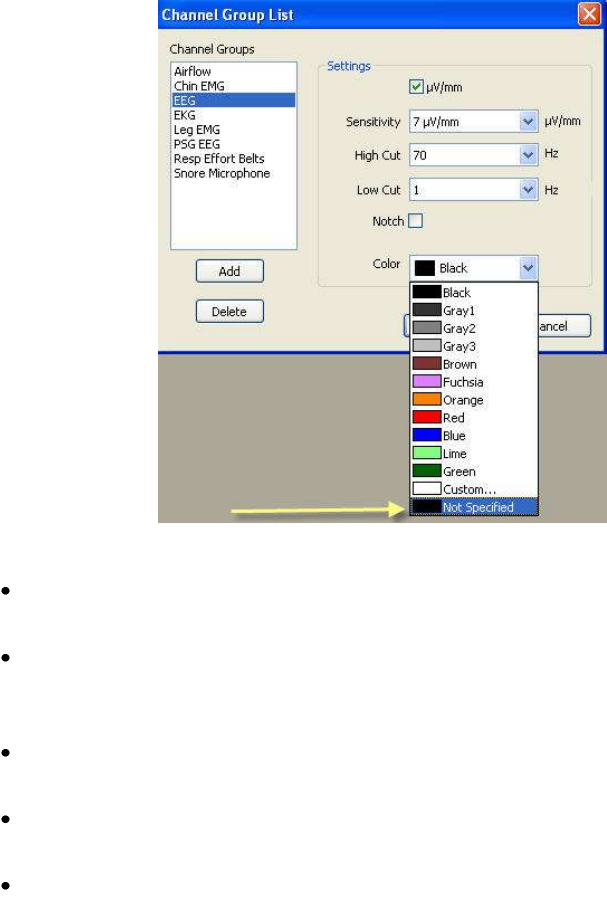
Cadwell Easy III
113
Edit Channel Group Settings
For any or each channel, modify the channel group settings. Add or delete channel
groups, set the scale to V/mm, set sensitivity, filters, notch filter and color. Selecting 'Not
Specified' as a Channel Group color will allow the user to apply different channel color
settings within a single montage.
Montage Rules
A notch filter setting may be turned on and off during data acquisition and
during review.
When active/reference pairs 1A-Ref, etc. are used, their references cannot be
changed during review. Usually these channels are unlinked and are used to
monitor non-EEG signals such as ECG or respiration.
If an active/reference pair is used, the active electrode cannot be used in any other
channel. For example, 4A-Ref and 4a-C3 cannot exist in the same montage.
Montages used during a recording are permanently saved with the record,
although you may select another montage for viewing at any time during review.
Even if you change the montage while reviewing, you can still re-display the EEG
as originally recorded.

Cadwell Easy III – Version 3.5
114
Average References
Average References can be used as a channel’s reference input, and can be defined from head
pattern or grid electrodes. Average references are built by combining several individual
reference inputs, such as all of the scalp electrodes, or A1 and A2 (linked ears). Add a new Avg
Ref by clicking the Add button, and then use the checkboxes to select Avg Ref electrodes. Click
OK to save.
Flash Programs
Follow your laboratory procedures and protocols while running the Cadwell Easy III Photic Stimulator.
An unlimited number of flash programs can be defined, each with an unlimited number of steps.
Photic stimulation is limited to a rate of 1-60 Hz.
Creating a Flash (Photic) Program
Click on Setup Flash Program. Click on Add.