CalAmp Wireless Networks 5016-500 Guardian 100 Wireless Radio Modem User Manual 1
CalAmp Wireless Networks Corporation Guardian 100 Wireless Radio Modem 1
UserManual.wiki
>
CalAmp Wireless Networks
>
5016 500 User Manual
Manual
Navigation menu
Upload a User Manual
Namespaces
Wiki Guide
HTML
PDF
Info
Views
User Manual
Discussion / Help
Navigation
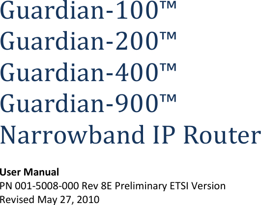

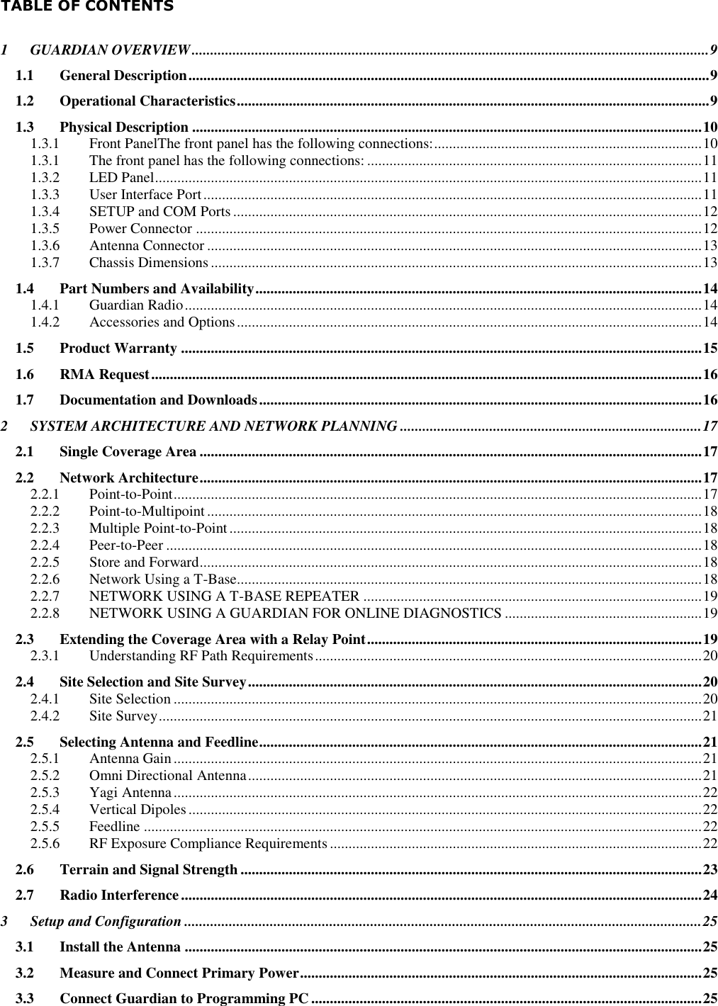
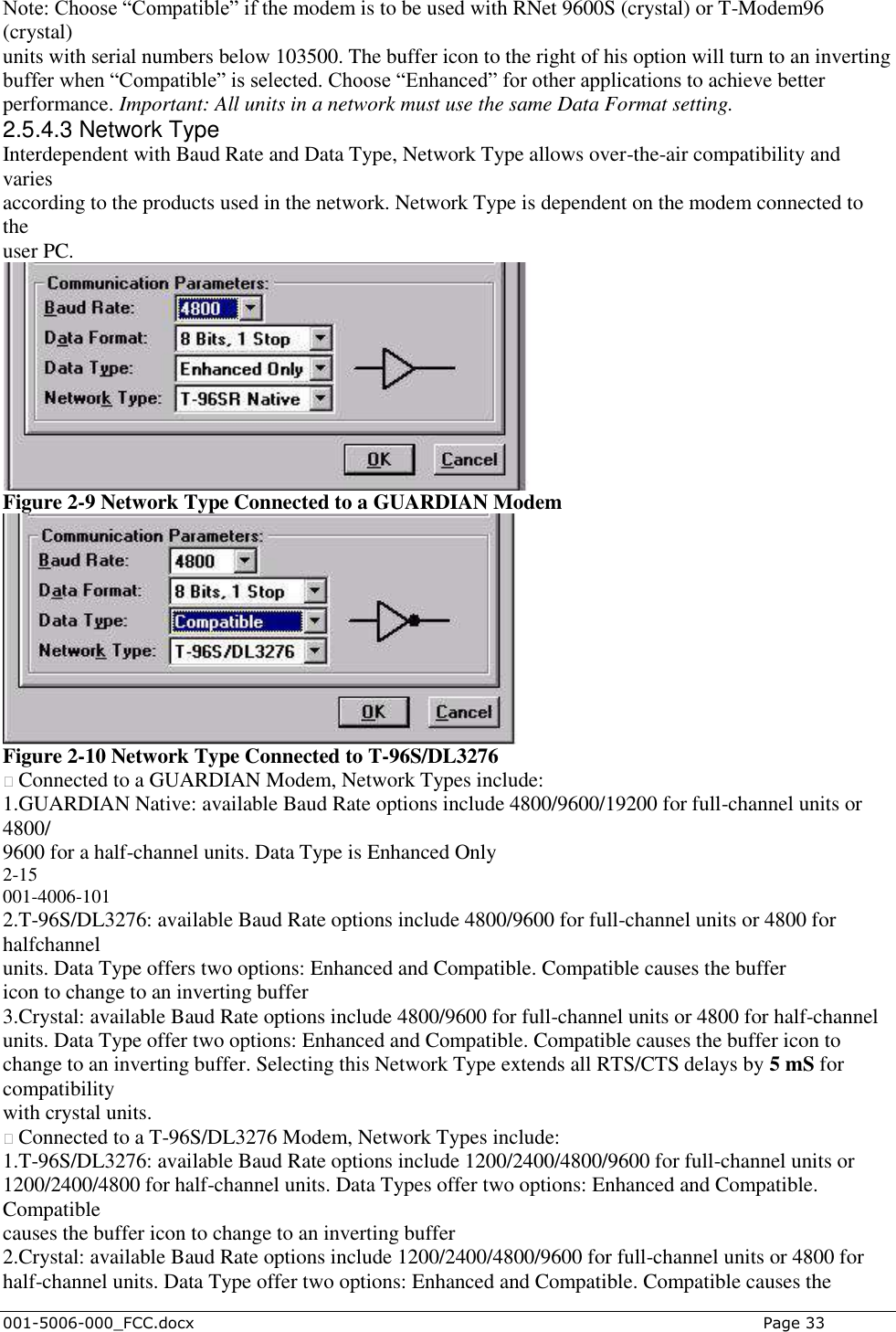
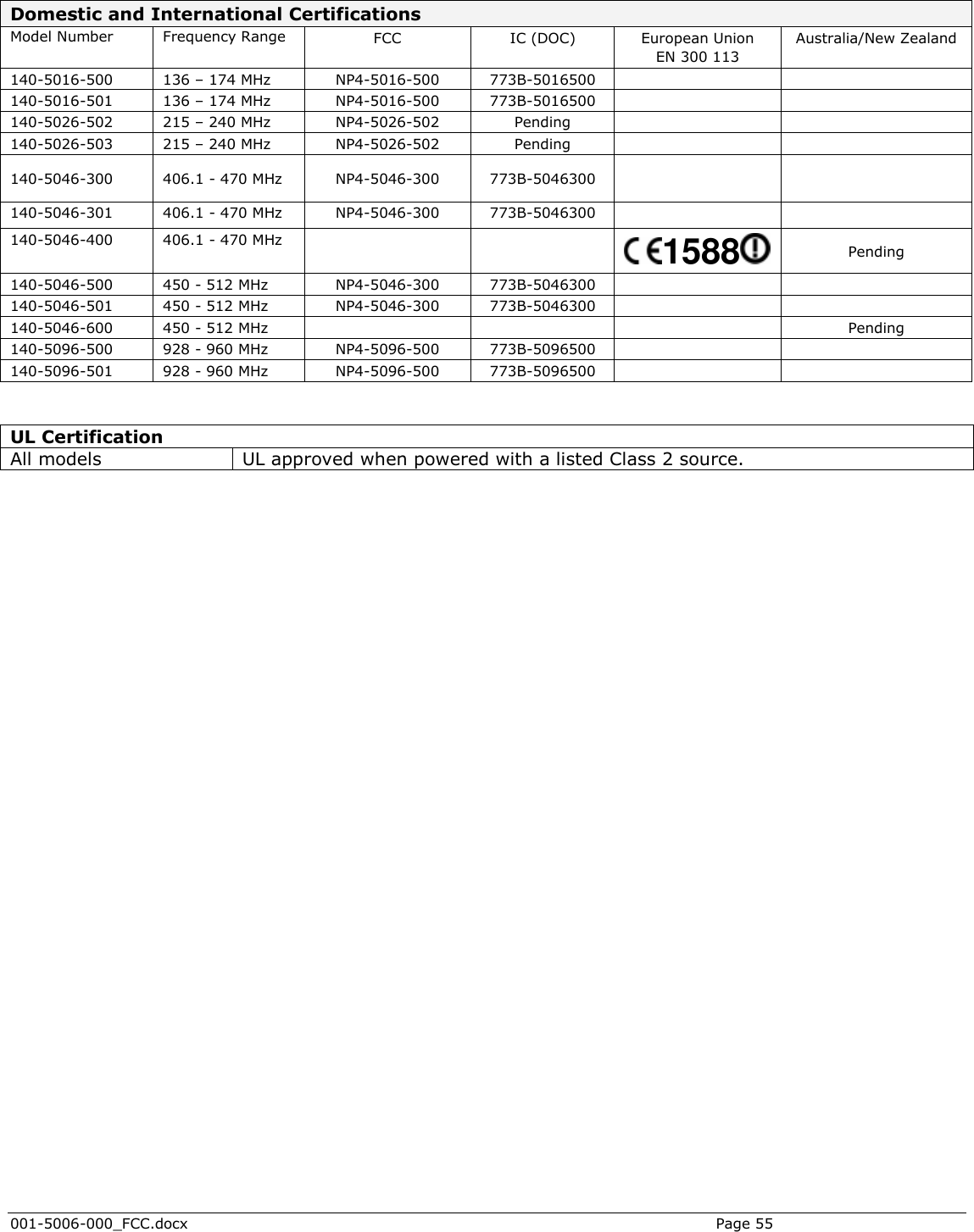
![REGULATORY CERTIFICATIONS The Guardian radio is available in several different models each with unique frequency bands. Each model of Guardian may have different regulatory approval as shown in the table below. UL Certification All models UL approved when powered with a listed Class 2 source. DECLARATION OF CONFORMITY FOR MODEL # 140-5046-400 This device (Guardian model #140-5046-400) is a data transceiver intended for commercial and industrial use in all EU and EFTA member states. Česky [Czech] CalAmp tímto prohlašuje, že tento rádio je ve shodě se základními požadavky a dalšími příslušnými ustanoveními směrnice 1999/5/ES. Dansk [Danish] Undertegnede CalAmp erklærer herved, at følgende udstyr radio overholder de væsentlige krav og øvrige relevante krav i direktiv 1999/5/EF. Deutsch [German] Hiermit erklärt CalAmp, dass sich das Gerät radio in Übereinstimmung mit den grundlegenden Anforderungen und den übrigen einschlägigen Bestimmungen der Richtlinie 1999/5/EG befindet. Eesti [Estonian] Käesolevaga kinnitab CalAmp seadme raadio vastavust direktiivi 1999/5/EÜ põhinõuetele ja nimetatud direktiivist tulenevatele teistele asjakohastele sätetele. English Hereby, CalAmp, declares that this radio is in compliance with the essential requirements and other relevant provisions of Directive 1999/5/EC. Español [Spanish] Por medio de la presente CalAmp declara que el radio cumple con los requisitos esenciales y cualesquiera otras disposiciones aplicables o exigibles de la Directiva 1999/5/CE. Ελληνική [Greek] ΜΕ ΣΗΝ ΠΑΡΟΤΑ CalAmp ΔΗΛΩΝΕΙ ΟΣΙ ΡΑΔΙΌΦΩΝΟ ΤΜΜΟΡΦΩΝΕΣΑΙ ΠΡΟ ΣΙ ΟΤΙΩΔΕΙ ΑΠΑΙΣΗΕΙ ΚΑΙ ΣΙ ΛΟΙΠΕ ΥΕΣΙΚΕ ΔΙΑΣΑΞΕΙ ΣΗ ΟΔΗΓΙΑ 1999/5/ΕΚ. Français [French] Par la présente CalAmp déclare que l'appareil radio est conforme aux exigences essentielles et aux autres dispositions pertinentes de la directive 1999/5/CE. Italiano [Italian] Con la presente CalAmp dichiara che questo radio è conforme ai requisiti essenziali ed alle altre disposizioni pertinenti stabilite dalla Certifications Model Number Frequency Range FCC IC (DOC) European Union EN 300 113 Australia/New Zealand 140-5016-500 136 – 174 MHz NP4-5016-500 773B-5016500 140-5016-501 136 – 174 MHz NP4-5016-500 773B-5016500 140-5026-500 216 – 222 MHz NP4-5026-500 773B-5026500 140-5026-501 216 – 222 MHz NP4-5026-500 773B-5026500 140-5046-300 406 - 470 MHz NP4-5046-500 773B-5046500 140-5046-301 406 - 470 MHz NP4-5046-500 773B-5046500 140-5046-500 450 - 512 MHz NP4-5046-500 773B-5046500 140-5046-501 450 - 512 MHz NP4-5046-500 773B-5046500 140-5096-500 928 - 960 MHz NP4-5096-500 773B-5096500 140-5096-501 928 - 960 MHz NP4-5096-500 773B-5096500](https://usermanual.wiki/CalAmp-Wireless-Networks/5016-500/User-Guide-1394248-Page-5.png)
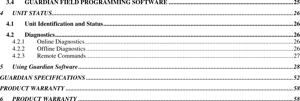
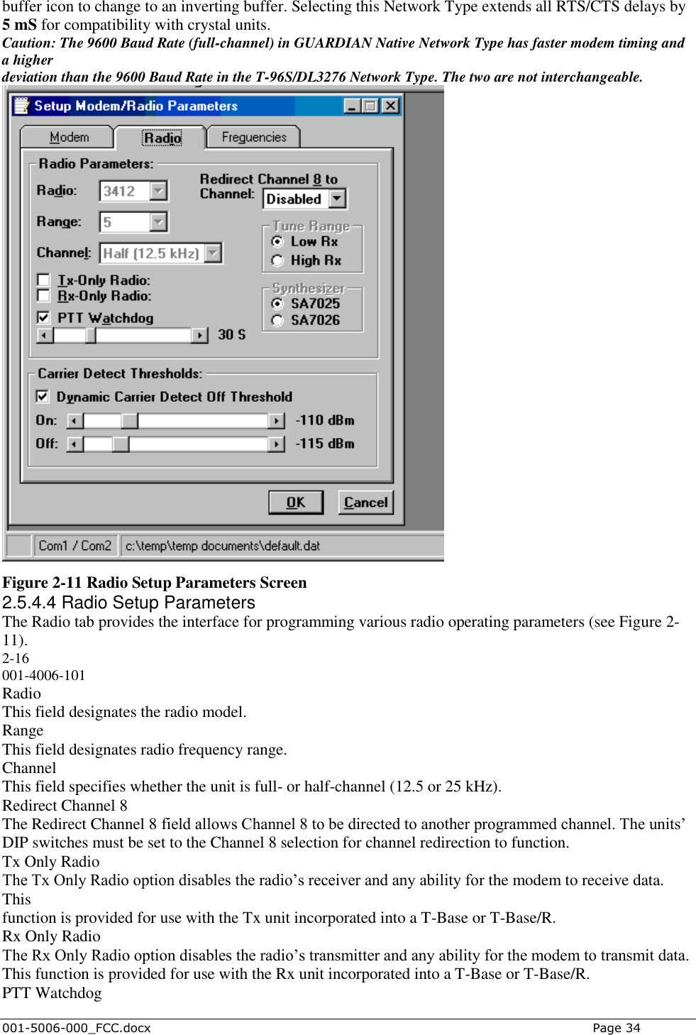
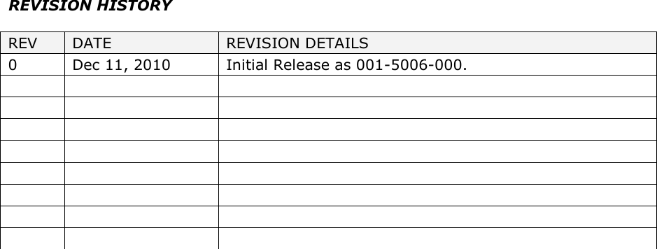
![direttiva 1999/5/CE. Latviski [Latvian] Ar šo CalAmp deklarē, ka radio atbilst Direktīvas 1999/5/EK būtiskajām prasībām un citiem ar to saistītajiem noteikumiem. Lietuvių [Lithuanian] Šiuo CalAmp deklaruoja, kad šis radijo atitinka esminius reikalavimus ir kitas 1999/5/EB Direktyvos nuostatas. Nederlands [Dutch] Hierbij verklaart CalAmp dat het toestel radio in overeenstemming is met de essentiële eisen en de andere relevante bepalingen van richtlijn 1999/5/EG. Malti [Maltese] Hawnhekk, CalAmp , jiddikjara li dan tar-radju jikkonforma mal-ħtiġijiet essenzjali u ma provvedimenti oħrajn relevanti li hemm fid-Dirrettiva 1999/5/EC. Magyar [Hungarian] Alulírott, CalAmp nyilatkozom, hogy a rádió megfelel a vonatkozó alapvetõ követelményeknek és az 1999/5/EC irányelv egyéb elõírásainak. Polski [Polish] Niniejszym CalAmp oświadcza, że radio jest zgodny z zasadniczymi wymogami oraz pozostałymi stosownymi postanowieniami Dyrektywy 1999/5/EC. Português [Portuguese] CalAmp declara que este rádio está conforme com os requisitos essenciais e outras disposições da Directiva 1999/5/CE. Slovensko [Slovenian] CalAmp izjavlja, da je ta radio v skladu z bistvenimi zahtevami in ostalimi relevantnimi določili direktive 1999/5/ES. Slovensky [Slovak] CalAmp týmto vyhlasuje, že rádio spĺňa základné požiadavky a všetky príslušné ustanovenia Smernice 1999/5/ES. Suomi [Finnish] CalAmp vakuuttaa täten että radio tyyppinen laite on direktiivin 1999/5/EY oleellisten vaatimusten ja sitä koskevien direktiivin muiden ehtojen mukainen. Svenska [Swedish] Härmed intygar CalAmp att denna radio står I överensstämmelse med de väsentliga egenskapskrav och övriga relevanta bestämmelser som framgår av direktiv 1999/5/EG. Íslenska [Icelandic] Hér með lýsir CalAmp yfir því að útvarp er í samræmi við grunnkröfur og aðrar kröfur, sem gerðar eru í tilskipun 1999/5/EC. Norsk [Norwegian] CalAmp erklærer herved at utstyret radio er i samsvar med de grunnleggende krav og øvrige relevante krav i direktiv 1999/5/EF.](https://usermanual.wiki/CalAmp-Wireless-Networks/5016-500/User-Guide-1394248-Page-6.png)